ST60 Compass Instrument Owner’s Handbook
50
ST60 Compass Instrument Owner’s Handbook Document number: 81107-4 Date: 1 April 2004
Transcript of ST60 Compass Instrument Owner’s Handbook

ST60 Compass InstrumentOwner’s Handbook
Document number: 81107-4
Date: 1 April 2004
Raymarine, ST60 and SeaTalk are trademarks of Raymarine Limited© Handbook contents copyright Raymarine Limited 2004

Preface i
Preface
Important information
Safety noticesWARNING: Product installation & operationThis equipment must be installed and operated in accordance with the Raymarine instructions provided. Failure to do so could result in personal injury, damage to your boat and/or poor product performance.
WARNING: Electrical safetyMake sure you have switched off the power supply before you start installing this product.
WARNING: Although we have designed this product to be accurate and reliable, many factors can affect its performance. Therefore, it should serve only as an aid to navigation and should never replace commonsense and navigational judgement. Always maintain a permanent watch so you can respond to situations as they develop.
EMC conformanceAll Raymarine equipment and accessories are designed to the best industry standards for use in the recreational marine environment.
The design and manufacture of Raymarine equipment and accessories conform to the appropriate Electromagnetic Compatibility (EMC) standards, but correct installation is required to ensure that performance is not compromised.
Handbook informationTo the best of our knowledge, the information in this handbook was correct when it went to press. However, Raymarine cannot accept liability for any inaccuracies or omissions it may contain.
In addition, our policy of continuous product improvement may change specifications without notice. Therefore, Raymarine cannot accept liability for any differences between the product and the handbook.

ii ST60 Compass Instrument Owner’s Handbook

Preface iii
ContentsPreface ......................................................................................................................i
Important information ..................................................................................... iSafety notices .......................................................................................... iEMC conformance ................................................................................... iHandbook information ............................................................................ i
Contents................................................................................................... iiiIntroduction ...................................................................................................viiData inputs ....................................................................................................vii
SeaTalk .................................................................................................viiiStand alone operation ..........................................................................viii
Remote control .............................................................................................viiiMounting options .........................................................................................viiiParts supplied ................................................................................................ ix
Chapter 1: Operation ............................................................................................11.1 Getting started ....................................................................................... 1
Displayed information ............................................................................ 1Digital display .................................................................................. 1Pointer ............................................................................................. 2
Use with Sea Talk autopilot .................................................................... 21.2 Normal operation ................................................................................... 2
Unlocked mode ...................................................................................... 3Course over ground (COG) ............................................................... 3Average heading .............................................................................. 3
Locked mode .......................................................................................... 4Operation ......................................................................................... 5
Auto mode ............................................................................................. 61.3 Display illumination ............................................................................... 61.4 Remote control ...................................................................................... 71.5 Operating hints ...................................................................................... 7
Steering sense ........................................................................................ 7Man overboard/reciprocal course .......................................................... 7
Chapter 2: Maintenance & Troubleshooting .....................................................92.1 Maintenance .......................................................................................... 9
Servicing and safety ............................................................................... 9Instrument ............................................................................................. 9Cabling ................................................................................................... 9
2.2 Troubleshooting ................................................................................... 10Preliminary procedures ........................................................................ 10Fault location ....................................................................................... 10

iv ST60 Compass Instrument Owner’s Handbook
Technical support ..................................................................................11World wide web .............................................................................11Telephone help line ........................................................................11Help us to help you .........................................................................11
Chapter 3: Installation .......................................................................................133.1 Planning your installation .....................................................................13
Site requirements .................................................................................13Transducer ......................................................................................13Instrument ......................................................................................14
EMC installation guidelines ..................................................................15Suppression ferrites ........................................................................16Connections to other equipment ....................................................16
3.2 Procedures ...........................................................................................17Unpacking ............................................................................................17Fitting the instrument ...........................................................................17
Surface mounting ...........................................................................17Flush mounting ..............................................................................18
Fitting the low-profile bezel ......................................................18Flush mounting procedure .......................................................20
Bracket mounting ...........................................................................21Fitting transducer .................................................................................21
Installation .....................................................................................21Running transducer cable ...............................................................22
General ....................................................................................22Connecting the instrument ...................................................................23
Introduction ...................................................................................23Signal connections .........................................................................23Power supply connections ..............................................................24
SeaTalk systems .......................................................................24Stand alone instruments ..........................................................24
Chapter 4: Calibration ........................................................................................274.1 Introduction ..........................................................................................27
EMC conformance ................................................................................274.2 User calibration ....................................................................................27
Linearization .........................................................................................28Heading alignment ...............................................................................28Lock mode ............................................................................................28Variation setting ...................................................................................29True/magnetic selection ........................................................................30Leaving User calibration .......................................................................30
4.3 Intermediate calibration .......................................................................30Software version number .....................................................................30

Preface v
Master/repeater status ......................................................................... 30Leaving Intermediate calibration ......................................................... 31
4.4 Dealer calibration ................................................................................. 31Calibration on/off ................................................................................. 32Pointer response .................................................................................. 32Heading display response .................................................................... 32Boat show mode .................................................................................. 32Factory defaults .................................................................................... 32Leaving Dealer calibration .................................................................... 33

vi ST60 Compass Instrument Owner’s Handbook

Preface vii
IntroductionThank you for purchasing a Raymarine product. We are sure your ST60 instrument will give you many years of trouble-free operation.
This handbook describes how to install and use the Raymarine ST60 Compass instrument. This instrument gives:• True/Magnetic Course Heading.• Current or Locked Heading.• Course Over Ground (COG).• Average Heading.
The ST60 Compass instrument is constructed in a rugged weather proofed case. It provides a sensitive and stable, combined analog and digital display, to deliver accurate information under even the most demanding conditions.
The ST60 Compass instrument provides Compass Heading, shown in digital form (numerals) plus (when in Locked mode) Steering Course Error to ±30° deviation of locked course heading, shown in analog form (pointer). The Compass instrument can be used either as a stand-alone unit, or as part of an integrated SeaTalk instrumentation system.
Data inputsThe ST60 Compass instrument receives data either from an associated Flux Gate Compass transducer and/or from a SeaTalk instrumentation system.
D4320-3

viii ST60 Compass Instrument Owner’s Handbook
SeaTalkSeaTalk enables a number of compatible instruments to be interconnected and operate as a single, integrated navigational system.
Power and data in a SeaTalk system are fed via a single cable, so that instruments can be connected by plugging them into the network. SeaTalk is flexible enough to adapt to any number of compatible instruments without requiring a central processor. SeaTalk can also communicate with non-SeaTalk equipment, using the internationally-accepted National Marine Electronics Association (NMEA) protocol.
In a SeaTalk system, each instrument can be either a master or dedicated repeater unit. A master instrument is directly connected to a transducer (the device that provides the raw data) and has control of all other equipment on the SeaTalk network. A slave instrument is not directly connected to a transducer but repeats information provided by other equipment in the SeaTalk network.
Stand alone operationIn Stand alone operation, the ST60 Compass instrument is connected only to the relevant transducer and does not display information from, or provide information to, any other instruments.
Remote controlWhen connected to SeaTalk, the ST60 Compass instrument can be controlled remotely by a SeaTalk Remote Keypad Unit, to provide instant remote access to the various display readouts from the ST60 range of equipment.
Mounting optionsIf you do not want to surface mount your ST60 instrument, options are available for:• Flush mounting. If you have ordered the flush mounting option a low-profile
bezel and four fixing screws are also provided.• Bracket mounting.

Preface ix
Parts suppliedUnpack your ST60 instrument and check that the following items are present:• Item 1, ST60 Compass instrument with standard bezel.• Item 2, Fixing studs (2).• Item 3, Thumb nuts (2).• Item 4, Gasket.• Item 5, Fluxgate Compass transducer.• Item 6, SeaTalk interconnection cable.• Item 7, Power cable.• Item 8, Instrument Cover.• Item 9, Owner’s Handbook. The Warranty document and mounting templates
are included in this Handbook.• Item 10, Cue Card.
Spare spade terminals are also provided, to re-terminate the transducer cable if it has to be cut to facilitate installation.
Note: Note: The above packing list is for an ST60 Compass system. Where an instrument is purchased separately, the Fluxgate Compass transducer is not included.

x ST60 Compass Instrument Owner’s Handbook
D4444-3
ST60 Steering CompassInstrumentOwner'sHandbook
1 4
8
32
32
5
6
7
109
COMPASS

Chapter 1: Operation 1
Chapter 1: Operation
1.1 Getting startedThis handbook describes how to operate, maintain and install the Raymarine ST60 Compass instrument. The Compass instrument shows both compass heading and steering indication. Where GPS or similar positioning data is available from another instrument, Course Over Ground (COG) can be calculated and used to provide a true course display.
CAUTION: Calibration requirementThe ST60 Compass instrument is calibrated to factory (default) settings when first supplied. To ensure optimum performance on your boat, this product must be calibrated before use. Do NOT use the product until it has been calibrated using the procedures in Chapter 4, Calibration.
If the CAL legend on the digital display flashes for the first 30 seconds after any power up, use the appropriate procedures in Chapter 4, Calibration to:1. Apply the factory defaults.2. Carry out the linearization procedure.
Displayed informationThe information displayed on the ST60 Compass instrument is presented by means of a pointer and a digital display. The pointer gives a steering indication and the digital display shows the compass heading.
Note: The TRUE and MAG indicators flash for 8 seconds after power is switched on. This is a function of the remote control system and can be ignored if remote control is not being used.
Digital displayThe digital display shows various course information:• True/Magnetic Course Heading, or• Locked Heading, or• Course Over Ground (COG), or• Average Heading.

2 ST60 Compass Instrument Owner’s Handbook
PointerIn locked mode, the analog pointer shows any course error between the current heading and the locked course, up to a maximum ±30º deviation. In unlocked mode, the pointer always indicates zero.
Note: When power is first switched on, the ST60 Compass starts in unlocked mode.
Use with Sea Talk autopilotIf the ST60 Compass instrument forms part of a system which includes a Sea Talk autopilot operating in Auto, Vane or Track mode, the ST60 Compass instrument is forced to operate in Auto mode.
In Auto mode the ST60 Compass instrument acts as a slave display to the autopilot, with the autopilot’s locked heading displayed on the ST60 Compass instrument digital display and the analog pointer showing the autopilot course error. In this mode, all ST60 Compass instrument key functions, except illumination, are disabled.
1.2 Normal operationUse the Basic operation and Using the disp key flow charts in this Chapter to operate your ST60 Compass instrument. The flow charts show the sequence of key presses and displays for the various operating tasks. All key presses called for in the flow charts are momentary, unless otherwise stated.
The displayed heading is either TRUE or MAG(netic) as indicated by a black square marker on the digital display, adjacent to the corresponding legend.
The ST60 Compass instrument has three modes of operation:• Unlocked - displays live course data.• Locked - displays course data and live course deviation data.• Auto - displays autopilot course data and live course deviation data.

Chapter 1: Operation 3
Unlocked modeThe Compass instrument always powers-up in the unlocked mode. The current heading is displayed on the digital display (true or magnetic) and the analog pointer indicates zero. Momentarily press the lock key to switch to locked mode.
Course over ground (COG)Press the disp key to select COG. Provided you have GPS or similar positioning data on the SeaTalk system, the ST60 Compass instrument displays your course over the ground. If such data is not available the digital display shows “---”.
Average headingPress the disp key again from the COG display to temporarily display the current calculated Average Heading. You can reset the average value by pressing the > key for 3 seconds when the Average heading screen is displayed.
D4387-2
Momentarily pressthe requiredkey
Basic operation
Press to toggle betweenlocked & unlocked modes.(see flow chart)Lock mode operation
Press to incrementlocked mode heading in 1 degree steps.
Keep pressedfor rapid change.
Press to decrementlocked mode heading in 1 degree steps.
(see flow chart)Using the disp key
In unlocked mode, press to accessCOG & average heading information.

4 ST60 Compass Instrument Owner’s Handbook
Locked modeLocked mode enables you to define a fixed (locked) heading then calculates any deviation from this locked heading. The digital display shows heading information and the pointer shows the difference between the locked heading and the actual course being steered, i.e. heading error.
Note: Modes marked *rely on external data.
D4388-1Using the disp key
Averageheading*
Course OverGround* (COG)
Normaldisplay
COG
TRUE MAG
Switch on
TRUE MAG TRUE MAG
AVE
disp
disp
disp
Press
for 3 secondsto reset average
Eitherlocked headingorcurrent heading
Heading error
Locked mode indications D4394-2
LOCK

Chapter 1: Operation 5
OperationTo enter locked mode (see the Locked mode operation illustration), press the lock key. The current heading is applied as the locked heading and flashes for 5 seconds, after which time the heading display shows either the locked heading or the current heading, depending on what has been set up during User calibration, as the normal display in locked mode (see Chapter 4, Calibration ).
to decrementlocked heading
To retrieve previous locked heading,press lock while display is flashing(i.e. within 5 seconds)
Press (momentarily)
Locked mode operation
To enter locked mode from unlocked mode
Lockedheading(flashing)
Heading
5 secondtimeout
Averagecourseerror(flashing)
Press
to incrementlocked heading
Press
Instrument now in unlocked mode
D4389-1
This screen shows either the current courseheading or the locked heading, depending on User
calibration set up (see ). Chapter 4, Calibration
5 secondtimeout
Press lock again to re-enter locked mode withthe current heading as the locked heading
To leave locked mode, press
TRUE MAG
TRUE MAG
TRUE MAG
TRUE MAG
TRUE MAG
LOCK
LOCK
LOCK
LOCK
lock
lock

6 ST60 Compass Instrument Owner’s Handbook
In locked mode you can use the < and > keys as necessary to change the locked heading.
To leave locked mode press the lock key. The average error flashes on the digital display for 5 seconds. If the average course steered has been to port of the locked heading, the display shows - ; if the average course steered has been to starboard, a positive value is displayed. If you press the lock key again within this 5 second period, you re-enter locked mode with the previously stored heading as the locked heading.
The average course error is reset to zero whenever the locked heading is changed.
Auto modeThe auto mode is activated automatically when the ST60 Compass instrument is connected to a SeaTalk compatible autopilot.
Whenever the autopilot is engaged, the heading set by the autopilot is displayed on the digital display and the analog pointer displays the autopilot’s course error.
Note: In Auto mode, all ST60 Compass instrument key functions, except illumination, are disabled.
1.3 Display illuminationWhen the instrument is first powered up, the display illumination is set to its lowest (courtesy) level, to facilitate access to the keys.
To adjust the level of display illumination:1. Hold down the disp key for approximately one second, to enter the illumina-
tion-adjust mode.2. There are four preset illumination levels from L0 to L4. Momentarily press the
disp key to cycle through these levels until you reach the level you want. The selected level is transmitted to all other instruments on the Sea Talk bus.
3. Press any other key to leave the illumination-adjust mode.
Note: The digital display will return to normal operation 7 seconds after the last key press.
A LOCK
Auto lock display D4450-1

Chapter 1: Operation 7
1.4 Remote controlWhen connected to SeaTalk, the ST60 Compass instrument can be controlled remotely with a SeaTalk Remote Keypad. Remote control of an instrument is indicated by flashing TRUE/MAG indicators on the ST60 Compass instrument digital display.
Details on how to use the remote control facility can be found in the SeaTalk Remote Keypad Owner’s Handbook.
1.5 Operating hints
Steering senseWhen the analog pointer indicates an off course error, steer the vessel in the direction you want the pointer to move.
Man overboard/reciprocal courseIf the vessel is turned through 110° or more when the ST60 Compass Instrument is in lock mode, the ST60 Compass Instrument automatically locks to the reciprocal of the original course (180° from the original). The digital display shows the reciprocal course and the pointer shows the course error from the reciprocal course.
The reciprocal course function is reversible, so that a second similar turn would lock onto the original locked course.
Note: The Man overboard/reciprocal course feature is not available when operating in Auto mode.

8 ST60 Compass Instrument Owner’s Handbook

Chapter 2: Maintenance & Troubleshooting 9
Chapter 2: Maintenance & Troubleshooting
2.1 Maintenance
Servicing and safety• Raymarine equipment should be serviced only by authorized Raymarine ser-
vice technicians. They will ensure that service procedures and replacement parts used will not affect performance. There are no user serviceable parts in any Raymarine product.
• Some products generate high voltages, so never handle the cables/connec-tors when power is being supplied to the equipment.
• When powered up, all electrical equipment produces electromagnetic fields. These can cause adjacent pieces of electrical equipment to interact with one another, with a consequent adverse effect on operation. In order to minimize these effects and enable you to get the best possible performance from your Raymarine equipment, guidelines are given in the installation instructions, to enable you to ensure minimum interaction between different items of equip-ment, i.e. ensure optimum Electromagnetic Compatibility (EMC).
• Always report any EMC-related problem to your nearest Raymarine dealer. We use such information to improve our quality standards.
• In some installations, it may not be possible to prevent the equipment from being affected by external influences. In general this will not damage the equipment but it can lead to spurious resetting action, or momentarily may result in faulty operation.
InstrumentCertain atmospheric conditions may cause condensation to form on the inside of the instrument window. This will not harm the instrument and can be cleared by increasing the illumination setting to Level 3.
Periodically clean your ST60 instrument with a soft damp cloth. Do NOT use chemical and/or abrasive materials to clean the instrument.
CablingExamine all cables for chafing or other damage to the outer shield and, where necessary, replace and re-secure.
10 ST60 Compass Instrument Owner’s Handbook
2.2 Troubleshooting
Preliminary proceduresChanges in the electronic environment may adversely affect the operation of your ST60 Compass instrument equipment. Typical examples of such changes are:• Electrical equipment has recently been installed or moved aboard your vessel.• You are in the vicinity of another vessel or shore station emitting radio signals.
If you appear to have a problem, first ensure that the EMC requirements (see Chapter 3, Installation ) are still being met before further investigating the problem.
Fault locationAll Raymarine products are subjected to comprehensive test and quality assurance programmes prior to packing and shipping. If a fault arises with the ST60 Compass instrument, the following table may help to identify the probable cause and provide the most likely cure.
Fault Cause Remedy
Display blank No power supply Check power supply.
Check SeaTalk cabling and connector security.
Check fuse/circuit breaker.
Displayed heading differs from that shown in vessel’s card compass.
Deviation present. Check for presence of large amounts of iron in the vicin-ity. If none present, recali-brate as detailed in Chapter 4 Calibration.
No transfer of information between instruments or a group of instruments (e.g. illumination levels).
SeaTalk cabling fault Check security of SeaTalk connectors.
Check the condition of SeaTalk cables.
Disconnect instruments one by one, to isolate faulty instrument.

Chapter 2: Maintenance & Troubleshooting 11
Technical supportRaymarine provides a comprehensive customer support service, on the world wide web and by telephone help line. Please use either of these facilities if you are unable to rectify a problem.
World wide webPlease visit the Customer Support area of our web site at:• www.raymarine.com
As well as providing a comprehensive Frequently Asked Questions section and servicing information, the web site gives e-mail access to the Raymarine Technical Support Department and a details of the locations of Raymarine agents, worldwide.
Telephone help lineIf you do not have access to the world wide web, please call our help line.
In the USA, call:• +1 800 539 5539, extension 2444 or• +1 603 881 5200 extension 2444
In the UK, Europe the Middle East or the Far East, call:• +44 (0) 23 9271 4713 (voice)• +44 (0) 23 9266 1228 (fax)
Help us to help youWhen requesting service, please quote the following product information:• Equipment type.• Model number.• Serial number.• Software issue number.
The Software issue number can be ascertained by means of the Intermediate Calibration facility, see Chapter 4, Calibration.

12 ST60 Compass Instrument Owner’s Handbook

Chapter 3: Installation 13
Chapter 3: InstallationThis chapter describes how to install the ST60 Compass instrument and associated Fluxgate Compass transducer. The transducer cable is connected to the rear of the instrument.
For advice, or further information regarding the installation of these products, please contact the Raymarine Product Support Department or your own National Distributor.
3.1 Planning your installationBefore starting the installation, spend some time considering the best positions for both transducer and instrument, such that the Site requirements and the EMC installation guidelines are satisfied.
Site requirements
TransducerFor optimum performance, the Fluxgate Compass transducer should be positioned as near as possible to the pitch/roll center of the vessel, as shown in the following illustration.
L
X
L
0.3L to 0.5L
0.3L to 0.5L
D4431-2

14 ST60 Compass Instrument Owner’s Handbook
The Fluxgate Compass transducer must also be sited:• At least 0.8 m (2 ft 6 in) away from the vessel's steering compass to avoid
deviation in both compasses.• On a bulkhead below deck.
Note: On steel vessels the Fluxgate Compass transducer can be mounted above deck. When mounted above deck, performance may be impaired due to increased motion.
• To allow reasonable access for installation and servicing.• Away from any equipment or other installation which may shield the trans-
ducer or otherwise disturb the earth’s magnetic field, e.g. large ferrous or magnetic items, communications equipment or cabling.
• On a vertical mounting surface. Where necessary, make up a suitable non-fer-rous wedged packing piece to provide the necessary vertical surface.
There must also be a viable route for the transducer cable to be routed to the instrument.
InstrumentCAUTION: The presence of moisture at the rear of the instrument could cause damage either by entering the instrument through the breathing hole or by coming into contact with the electrical connectors.
ST60 instruments can be fitted either above or below deck, provided the rear of the instrument is sited where it is protected from contact with water.
Each instrument must also be positioned where it is:• Easily read by the helmsman.• Protected against physical damage.• At least 9 in (230 mm) from a compass.• At least 20 in (500 mm) from radio receiving equipment.• Reasonably accessible from the rear for installation and servicing.
3 in (76 mm )
D729-7
3 in (76 mm )
Fluxgate Compass transducer dimensions

Chapter 3: Installation 15
EMC installation guidelinesAll Raymarine equipment and accessories are designed to the best industry standards for use in the recreational marine environment.
Their design and manufacture conforms to the appropriate Electromagnetic Compatibility (EMC) standards, but correct installation is required to ensure that performance is not compromised. Although every effort has been taken to ensure that they will perform under all conditions, it is important to understand what factors could affect the operation of the product.
The guidelines given here describe the conditions for optimum EMC performance, but it is recognized that it may not be possible to meet all of these conditions in all situations. To ensure the best possible conditions for EMC performance within the constraints imposed by any location, always ensure the maximum separation possible between different items of electrical equipment.
4.33 in (110 mm) 0.95 in(24 mm)
0.6 in(15 mm)
3.54
in (9
0 m
m)
diam
eter
4.53
in (1
15 m
m)
4.85 in (123 mm) 0.25 in(6.2 mm)
1.4 in(35 mm)
3.54
in (9
0 m
m)
diam
eter
4.85
in (1
23 m
m)
D5785-4ST60 instrument dimensions
With standardbezel
With lowprofile bezel

16 ST60 Compass Instrument Owner’s Handbook
For optimum EMC performance, it is recommended that wherever possible:• Raymarine equipment and cables connected to it are:
• At least 3 ft (1 m) from any equipment transmitting or cables carrying radio signals e.g. VHF radios, cables and antennas. In the case of SSB radios, the distance should be increased to 7 ft (2 m).
• More than 7 ft (2 m) from the path of a radar beam. A radar beam can nor-mally be assumed to spread 20 degrees above and below the radiating element.
• The equipment is supplied from a separate battery from that used for engine start. Voltage drops below 10 V in the power supply to our products, and starter motor transients, can cause the equipment to reset. This will not dam-age the equipment, but may cause the loss of some information and may change the operating mode.
• Raymarine specified cables are used. Cutting and rejoining these cables can compromise EMC performance and must be avoided unless doing so is detailed in the installation manual.
• If a suppression ferrite is attached to a cable, this ferrite should not be removed. If the ferrite needs to be removed during installation it must be reas-sembled in the same position.
Suppression ferritesThe following illustration shows typical cable suppression ferrites used with Raymarine equipment. Always use the ferrites supplied by Raymarine.
Connections to other equipmentIf your Raymarine equipment is to be connected to other equipment using a cable not supplied by Raymarine, a suppression ferrite MUST always be attached to the cable near the Raymarine unit.
D3548-6

Chapter 3: Installation 17
3.2 ProceduresAs it is not possible to describe procedures for all possible installation scenarios, the procedures given here describe the broad requirements for installing an ST60 Compass instrument and its associated Fluxgate Compass Transducer. Adapt these procedures as appropriate, to suit your individual requirement.
CAUTION: Where it is necessary to cut holes (e.g. for cable routing and instrument mounting), ensure that these will not cause a hazard by weakening critical parts of the vessel’s structure.
UnpackingUnpack your ST60 instrument and check that the items described in the Preface are present.
Each ST60 instrument is supplied with a standard bezel for surface mounting. Optional mounting kits are available for flush mounting and bracket mounting the instrument. If you have ordered the flush mounting option, a low-profile bezel and four fixing screws are also provided.
Fitting the instrumentThe ST60 Compass instrument can be installed using one of a number of different mounting options:• Surface Mounting. Gives a profile of approximately 0.95 in (24 mm).• Flush Mounting. Gives a profile of approximately 0.25 in (6 mm).• Bracket Mounting.
The ST60 Compass instrument can also be mounted behind a panel with just the instrument dial and keys visible.
Surface mountingTo surface mount your ST60 instrument (see the Surface mounting illustration):1. Ensure that:
• The selected location is clean, smooth and flat.• There is sufficient space behind the location to accommodate the rear of
the instrument and connectors.2. Apply the surface mount template (supplied at the rear of this handbook) to
the selected location and mark the centers for the fixing studs (1) and the aperture (3) that will take the rear casing of the instrument.

18 ST60 Compass Instrument Owner’s Handbook
3. Drill out the two 0.2 in (5 mm) fixing stud clearance holes (2). 4. Cut out the clearance hole (3) then remove the template.5. Peel off the protective sheet from the self-adhesive gasket (4) then stick the
gasket into position on the rear of the instrument.6. Screw the two fixing studs into the threaded sockets on the rear of the instru-
ment.7. Mount the assembled instrument, studs, bezel and gasket into the panel.
Secure from behind with the thumb nuts (5).
Flush mountingThe Flush Mounting Kit uses a low-profile bezel to reduce the fitted profile of the instrument to approximately 0.25 in (6 mm) above the panel fascia.
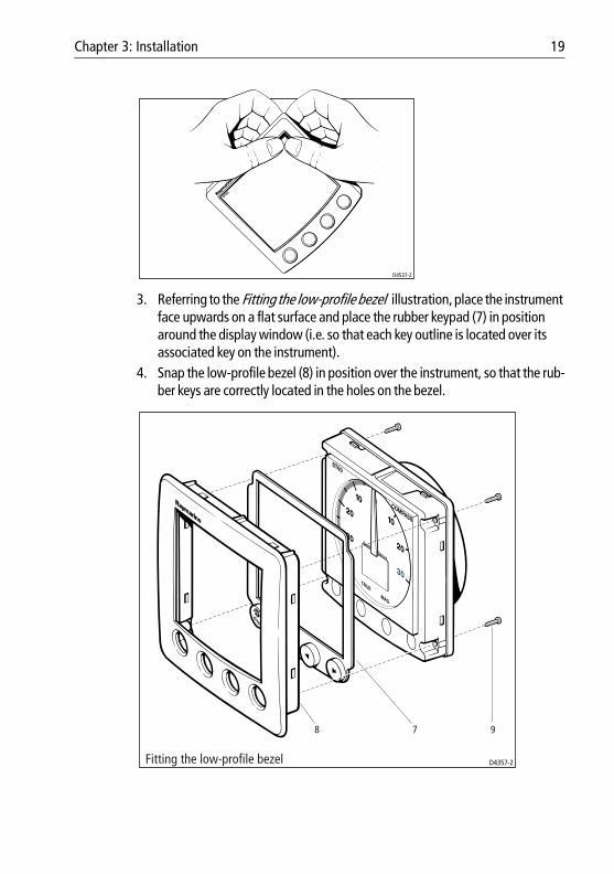
Fitting the low-profile bezelIn order to flush-mount your ST60 instrument, replace the standard bezel with the low-profile bezel as follows:1. Hold the instrument in both hands with the display towards you.2. Using both thumbs, gently press an upper corner of the instrument from the
bezel, then remove the bezel from the instrument. Retain the rubber keypad which is released when the bezel is removed.
D4328-2Surface mounting4 1 2 1 3 5 2 5
Chapter 3: Installation 19
3. Referring to the Fitting the low-profile bezel illustration, place the instrument face upwards on a flat surface and place the rubber keypad (7) in position around the display window (i.e. so that each key outline is located over its associated key on the instrument).
4. Snap the low-profile bezel (8) in position over the instrument, so that the rub-ber keys are correctly located in the holes on the bezel.
D4537-2
D4357-2Fitting the low-profile bezel
78 9

20 ST60 Compass Instrument Owner’s Handbook
CAUTION: It is essential that only screws of the correct size are used to secure the instrument to the bezel. Failure to observe this caution could result in damage to both the instrument and the bezel.
5. Using the four, self-tapping screws (9) provided, secure the instrument and bezel together. Fit the screws from the rear of the instrument and tighten them sufficiently to secure the instrument and bezel together. DO NOT OVER-TIGHTEN.
Flush mounting procedureFlush mount your instrument (see the Flush mounting illustration) as follows:1. Assemble the ST60 instrument and low-profile bezel as described under Fit-
ting the low-profile bezel.2. Ensure that:
• The panel on which you intend to mount the instrument is between 0.12 in (3 mm) and 0.78 in (20 mm) thickness.
• The selected location is clean, smooth and flat.• There is sufficient space behind the location to accommodate the rear of
the instrument and connectors.
Flush mounting D4329-2
4
31 1 5 6 5

Chapter 3: Installation 21
3. Apply the template flush mount (supplied at the rear of this handbook) to the selected location and mark out the aperture into which the assembled instru-ment and bezel will sit.
4. Cut out the aperture (3) for the assembled instrument and bezel and remove the template.
5. Peel off the protective sheet from the self-adhesive gasket (4) then stick the gasket into position on the rear of the bezel.
6. Screw the two fixing studs (1) into the threaded sockets on the rear of the instrument.
7. Mount the assembled instrument, studs, bezel and gasket into the panel. 8. Locate the flush mount bracket (6) onto the fixing studs and secure the assem-
bly to the panel with the thumb-nuts (5).
Bracket mountingA Control Unit Mounting Bracket (Part No. E25009) enables you to mount your ST60 instrument in locations where other forms of mounting are impractical. Although this provides a useful alternative method for securing your instrument, it is only suitable for use in positions where the instrument will not be exposed to water.
To bracket mount your ST60 instrument, do so in accordance with the Control Unit Mounting Bracket Instruction Sheet.
Fitting transducerIf you are fitting an ST60 Compass instrument and wish to use it as a stand alone instrument, you need to fit a Fluxgate Compass transducer.
Note: If the ST60 Compass instrument is to form part of a system which includes a SeaTalk autopilot, the ST60 Compass instrument does not need its associated Fluxgate Compass transducer to operate as a slave to the autopilot. However, if the Fluxgate Compass trans-ducer is fitted, the instrument will operate as a master.
InstallationDetermine a suitable position for the Fluxgate Compass transducer, as described under Site requirements.
If you are not sure of the magnetic suitability of the chosen location, carry out a survey of the site as follows:1. Temporarily fix a simple hand bearing compass at the intended location.2. Swing the vessel through 360° while at the same time observing differences
between the hand bearing compass and the vessel's main steering compass.

22 ST60 Compass Instrument Owner’s Handbook
3. If there are no differences, greater than 10° on any heading, then the site is suitable for the Fluxgate Compass transducer.
Using the self-tapping screws provided, mount the Fluxgate Compass transducer vertically on a suitable bulkhead, so that the connecting cable is downmost.
Running transducer cable
GeneralThe manner in which you run the cable from the Fluxgate Compass transducer will depend on the locations of the transducer and instrument. The following guidelines are provided:• If the cable has to be fed through the deck, always use a proprietary deck
gland.• Where cables are fed through holes, always use grommets to prevent chafing.• Secure long cable runs so they do not present a hazard.• Although the transducer cable is fitted with spade connectors for direct con-
nection to the rear of the instrument, it may be necessary to remove these to facilitate installation e.g. if you want incorporate a junction box in the cable run or if the cable has to be routed through narrow apertures. Extra spade connectors are provided, to replace any that are removed when running the cable. When fitting spade connectors, prepare the cable as at (a) in the follow-ing illustration, then fold back the wire strands and insert into the spade con-nector as at (b). Ensure the wire strands do not extend beyond the rear of the spade connector insulation, then crimp the connector to the wire.
3 mm
6 mm50 mm
(a)
(b)D4467-6

Chapter 3: Installation 23
Connecting the instrument
IntroductionThe ST60 Compass instrument can be connected to SeaTalk as a repeater instrument.
The ST60 Compass instrument can also be connected:• As a stand-alone instrument connected directly to the Fluxgate Compass
transducer.• To fulfil both slave (repeater) and master roles by being connected both to the
Fluxgate Compass transducer and to SeaTalk.
Instruments connected to SeaTalk derive their power directly from SeaTalk and no separate power connection is necessary. Where a SeaTalk system includes an autopilot, the power for the system is provided by the autopilot.
A range of Raymarine SeaTalk extension cables is available to connect separated instruments. These cables are supplied with a SeaTalk connector fitted to each end. A junction box can be used to join cables.
Signal connectionsMake the necessary connections to your ST60 instrument (see the Connection to ST60 Compass instrument illustration).
D4390-2
Cable from Fluxgate Compass transducer
Connections to ST60 Steering Compass instrument
SeaTalk cable SeaTalk cable
ScreenBlueGreenYellowRed

24 ST60 Compass Instrument Owner’s Handbook
Power supply connections
SeaTalk systemsCAUTION: When instruments are connected to SeaTalk, ensure that the power supply for the SeaTalk 12 V line is protected by a 5 A fuse.
Systems with a large number of instruments on the SeaTalk bus may require connections to the power supply from each end of the system (‘ring-main’ style), to maintain sufficient voltage throughout the system.
This requirement depends on the total length of the cable run and the total number of instruments in the system, as follows:
Stand alone instrumentsStand-alone instruments are not connected to SeaTalk and therefore need to be connected to an alternative 12 V power source. Power cables are available in 2 m and 9 m lengths.
Cable run No. of instruments Power connections
Up to 10 m 13 maximum 1
26 maximum 2
Up to 20 m 7 maximum 1
13 maximum 2
D4311-1
5 A fused,12 V dc supply
(typically providedby autopilot)
Red
Screen
Red
Screen
1 2 3 4
Instruments5 to 16
17181920
SeaTalk power connections

Chapter 3: Installation 25
To fit a power cable:1. Ensure the intended power source is switched off.2. Run the power cable from the instrument to a suitable 12 V dc power source.3. If the cable has not already been trimmed at the power supply end:
i. Cut the cable to length and trim back an appropriate amount of the outer sheath.
ii. Cut back and insulate the yellow wire.4. Connect the screen to the power supply 0 V terminal.5. Connect the red wire via a 3 A circuit breaker to the power supply +12 V ter-
minal.6. Insert the power cable connector into one of the SeaTalk connectors at the
rear of the instrument.
Power connections for stand-alone instrument
12 V dcsupply
3 A over-currentcircuit breaker
Red
Screen
D4310-3

26 ST60 Compass Instrument Owner’s Handbook

Chapter 4: Calibration 27
Chapter 4: Calibration
4.1 IntroductionThe ST60 Compass instrument is set up with factory-programmed default settings, so in order to optimize the performance of the instrument on board a particular vessel, the procedures in this Chapter must be carried out immediately after the completion of installation and before the equipment is used for navigational purposes.
Where practicable, the calibration procedures are presented diagrammatically to show the sequence of key presses and the resulting displays. If a parameter is adjustable, adjustment instructions are given at the appropriate point on the diagram.
EMC conformance• Always check the installation before going to sea to make sure that it is not
affected by radio transmissions, engine starting etc.• In some installations, it may not be possible to prevent the equipment from
being affected by external influences. Although this will not damage the equipment, it can lead to spurious resetting action, or momentarily may result in faulty operation.
4.2 User calibrationThe User calibration procedures (see the User calibration flow chart) enable you to carry out:• Linearization and heading alignment.• Locked heading display selection.• Variation setting.• True/Magnetic display selection.
Note: User Calibration is possible only if it is enabled (default) in Dealer Calibration.
To carry out a User calibration:1. Hold down the disp and lock keys together for approximately 2 seconds to
select the Calibration entry screen.2. Use the disp key to cycle from screen to screen and use the < and > keys to set
the required values at each screen.

28 ST60 Compass Instrument Owner’s Handbook
LinearizationThe Fluxgate Compass transducer must be linearized to compensate for deviation. Linearization should be carried out in calm conditions, preferably in flat water.
Note: If linearization has already been performed, press the disp key momentarily to by-pass the linearization process and carry on to the Heading alignment screen without dis-turbing the current deviation settings.
When the Linearization screen is first selected, the outer segments of the LCD cycle to indicate that linearization has started.
To proceed with the linearization, slowly turn the vessel in a circle, so that the speed is kept below 2 knots and so that it takes at least 3 minutes to complete 360°. If the vessel is turning too quickly, the buzzer will sound and a SLO message will flash on the digital display. If this occurs, slow down the vessel’s rate of turn.
Keep turning until the digital display shows a flashing heading value. Linearization is now complete and the digital display now advances automatically to the Heading alignment screen.
Note the analog pointer reading which shows the amount of deviation corrected. If this reading exceeds 15°, the Fluxgate Compass transducer should be re-sited.
Heading alignmentCarry out heading alignment as follows:1. Align the vessel with a known bearing; preferably a transit bearing.2. Use the < and > keys to adjust the value on the ST60 Compass instrument dig-
ital display until it corresponds to the known bearing.
Lock modeThe locked mode screen enables you to select which heading is selected as the normal operating display in locked mode. This can be either:• The locked or ‘fixed’ heading.
or
• The live or ‘current’ heading.
Use the < and > keys as necessary, to select the required heading. Select:• F for Fixed heading.• C for Current heading.

Chapter 4: Calibration 29
Variation settingA positive value indicates easterly and a negative value westerly. If the variation has not been set, or the data is not available, the digital display shows a series of dashes.
Changes to variation must be accepted before a TRUE heading can be selected, (see True/magnetic selection below).
If the ST60 Compass instrument is connected to SeaTalk and a value for variation is present on SeaTalk (e.g. from an autopilot), this is accepted as the value for the instrument. If a value is not present on SeaTalk, or if the instrument is not connected to SeaTalk, use the < and > keys to set the appropriate value.
D4391-1User Calibration
Press either
or
Hold down and for approximately 2 seconds
CAL
TRUE MAG
CalibrationEntry Screen
Linearisation
Headingalignment
CAL
TRUE MAG
CAL
TRUE MAG
TRUE MAG
CAL
TRUE MAG
Lock Mode
VariationSetting
True/MagneticSelection
to set the required values
CAL
TRUE MAG
displock
disp
disp
dispdisp
disp
disp
30 ST60 Compass Instrument Owner’s Handbook
True/magnetic selectionUse this option to select either MAG (netic) or TRUE as the heading display default (indicated by the black square adjacent to either MAG or TRUE , as appropriate).
If theST60 Compass instrument is used in a system without a SeaTalk compatible Autopilot, or it is being used independently, set the digital display to MAG .
True headings cannot be displayed if variation data is not available.
Leaving User calibrationPress the disp and lock keys for 2 seconds, to save your changes, exit User calibration and return to normal operation.
4.3 Intermediate calibrationThe Intermediate calibration procedures (see the Intermediate calibration flow chart) enable you see:• Software version number.• Master/Repeater status.
To access the intermediate calibration information, hold down the disp and lock keys together for approximately 4 seconds.
Software version numberThis screen shows the Software Version number. This information is normally required when requesting parts or repairs.
Master/repeater statusPress the disp key from the Software Version Number screen to enter the Master/Repeater Status screen.
The display shows either:• r0 to indicate a master instrument, i.e. connected to a transducer
or• r1 to indicate a repeater instrument, i.e. using data from SeaTalk.

Chapter 4: Calibration 31
Leaving Intermediate calibrationPress the disp and lock keys for 2 seconds, to exit Intermediate calibration and return to normal operation.
4.4 Dealer calibrationDealer Calibration enables the following parameters to be set:• User calibration on/off.• Pointer response.• Heading display response.• Boat show mode on/off.
Dealer calibration also gives access to the Factory defaults screen. This enables you to re-apply the factory settings if you want to reset the instrument to a known operating condition.
To commence Dealer calibration, hold down the disp and lock keys together for approximately 12 seconds to select the Dealer calibration entry screen (see Dealer calibration flow chart). Then press the < and > keys simultaneously, to start the calibration sequence.
D4395-1Intermediate Calibration
Press and For 2 secondsto exit Intermediate calibration
Hold down and for approximately 4 seconds
Software versionnumber
Instrumentstatus
CAL
TRUE MAG
r 0 = masterr 1 = repeater
CAL
TRUE MAG
displock
displock
disp

32 ST60 Compass Instrument Owner’s Handbook
Calibration on/offControls access to the User calibration. Access can be either enabled ( UC1 ) or disabled ( UC0 ), as required.
Use the < and > keys to set the value you want.
Note: If the access to User calibration is disabled, then only the software version screen will be available in Intermediate calibration; the instrument status screen will not be dis-played.
Pointer responseThe pointer response value determines how the analog pointer responds to changes in data inputs. The higher the value, the more sensitive the pointer to data changes. The range is from P1 to P15.
Use the < and > keys to set the value you want.
Heading display responseThe heading display response value determines how the digital display responds to changes in data inputs. The higher the value, the more sensitive the display to data changes. The range is from d1 to d15.
Use the < and > keys to set the value you want.
Boat show modeCAUTION: DO NOT enable this mode. It must be used for demonstration purposes only.
Ensure that Boat Show Mode is set to bS0 (disabled). If necessary, use either the < key or the > key to achieve this.
Factory defaultsYou can use this screen to reset the operating parameters to the factory default values. Use the < and > keys to make the required selection.
Note that the selection you make at this screen will be applied when you exit the screen, so be sure you make the correct selection.
If you want to apply the factory defaults, ensure the display shows F1 , but if you want to retain the current values, ensure that the display shows F0 .

Chapter 4: Calibration 33
Leaving Dealer calibrationHold down the disp and lock keys for 2 seconds, to save your changes, exit Dealer calibration and resume normal operation.
D4393-1Dealer Calibration
Entryscreen
andHold down for approximately 12 seconds
CAL
TRUE MAG
Calibrationon/off
CAL
TRUE MAG
Press either
or
to set the required values
Pointerresponse
CAL
TRUE MAG
Boatshowmode
CAL
TRUE MAG
Headingdisplay
response
CAL
TRUE MAG
and
CAL
TRUE MAG
disp
disp
disp
disp
disp
disp
Factorydefaults
lock

34 ST60 Compass Instrument Owner’s Handbook

D4436-1
Machine hole90mm (3.54in)
diameter
Drill 5mm (3/16in) diameter
Drill 5mm (3/16in) diameter
Shaded areas to be removed
TOPST60 Surface Mount Template


Shaded area to be removed
TOP
109 mm
ST60 Flush Mount Template
114
mm
4 holes6 mm diameter
D4437-1