SSI Manual Rev 1-2 - TransducerTechniques Manual Rev 1-2.pdf · - 3 3. SSI PRODUCT INTRODUCTION The...
33
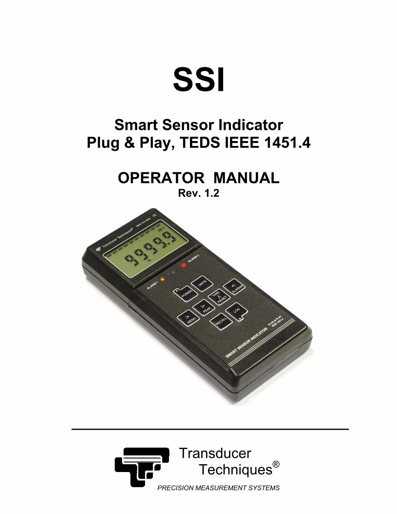
SSI Smart Sensor Indicator Plug & Play, TEDS IEEE 1451.4 OPERATOR MANUAL Rev. 1.2 Transducer Techniques ® PRECISION MEASUREMENT SYSTEMS
Transcript of SSI Manual Rev 1-2 - TransducerTechniques Manual Rev 1-2.pdf · - 3 3. SSI PRODUCT INTRODUCTION The...
SSI
Smart Sensor Indicator Plug & Play, TEDS IEEE 1451.4
OPERATOR MANUAL
Rev. 1.2
Transducer Techniques®
PRECISION MEASUREMENT SYSTEMS
- 2
1. TABLE OF CONTENTS
1. TABLE OF CONTENTS................................................................................................. 2
2. TEDS IEEE 1451.4 INTRODUCTION............................................................................ 2
3. SSI PRODUCT INTRODUCTION.................................................................................. 3
4. RECEIVING & UNPACKING ......................................................................................... 4
5. SAFETY CONSIDERATIONS & CARE OF YOUR METER.......................................... 5
6. CONNECTOR WIRING INFORMATION ....................................................................... 6
7. KEYPAD OPERATION .................................................................................................. 7
8. DATA LOGGING & RECALL OPERATION................................................................... 10
9. MENU MODE PROGRAMMING FUNDAMENTALS..................................................... 14
10. MENU MODE PROGRAMMING KEYSTROKES .......................................................... 17
11. INSTRUMENT SETUP VIA PC...................................................................................... 23
12. CUSTOM CURVE LINEARIZATION.............................................................................. 25
13. METER CALIBRATION ................................................................................................. 26
14. 7-SEGMENT ALPHABET .............................................................................................. 26
15. SPECIFICATIONS ......................................................................................................... 27
16. GLOSSARY OF TERMS................................................................................................ 29
17. WARRANTY & REPAIR POLICY .................................................................................. 31
2. TEDS IEEE 1451.4 INTRODUCTION
The SSI Smart Sensor Indicator is a TEDS IEEE 1451.4 Plug and Play Smart Load Cell Meter.
TEDS, or Transducer Electronic Data Sheet, is a set of electronic data in a standardized format defined within the IEEE 1451.4 standard. The data is stored in an EEPROM with the sensor. It specifies what type of sensor is present, describes its interface, and gives tech-nical information such as sensitivity, bridge type, and excitation.
The SSI automatically detects when a TEDS IEEE 1451.4 compliant Load Cell, Torque Sensor or Pressure Transducer is connected. Once a TEDS sensor is detected, the SSI displays “TEDS”, reads the EEPROM, stores the information in memory, and performs an automatic configuration.
The built-in sensor-related EEPROM may be any of the following types: DS1973/DS2433, DS2431 or DS1971/DS2430A. The automatic system configuration function performs all steps needed to calibrate the TEDS IEEE 1451.4 compliant sensor and SSI as a system. This includes the configured precision of either 32 bits, 19 bits or 11 bits.
Using the SSI with a TEDS IEEE 1451.4 compliant Load Cell, Torque Sensor or Pressure Transducer is as easy as plugging a mouse into a computer, making it a true plug-and-play experience.
The SSI may also be used with a non-TEDS sensor requiring manual configuration and calibration.
- 3
3. SSI PRODUCT INTRODUCTION
The SSI Smart Sensor Indicator is a hand-held, programmable meter and datalogger for load, torque or pressure applications. Advanced capabilities include:
1. “Plug and Play” operation with automatic scaling at power-up with TEDS IEEE 1451.4 compliant load cells.
2. Menu-driven scaling of non-TEDS-compliant load cells via keypad with a choice of two scaling methods: manually entered coordinates of two points, or reading coordinates of two points using input signals.
3. PC-based scaling of non-TEDS-compliant load cells using Instrument Setup software, again with a choice of two scaling methods.
4. Keypad selectable units of measure for load, torque or pressure, with automatic con-version of readings between units.
5. Lockout feature to simplify meter operations and prevent inadvertent changes.
6. Ultra-fast signal sampling rate of 15,360 samples/second (when set for 60 Hz noise rejection) or 12,800 samples/second (when set for 50 Hz noise rejection).
7. Normal conversion rate of 60/second (when set for 60 Hz noise rejection) or 50/second (when set for 50 Hz noise rejection), with digital averaging of every 256 samples. Allows display of filtered or unfiltered readings, capture of Peak, First Peak or Valley.
8. Selectable Fast conversion rates up to 7,680/second (when set for 60 Hz noise rejection) or 6,400/second (when set for 50 Hz noise rejection). Always unfiltered, allows capture of Peak or First Peak.
9. Display update rate at 3.75/second (when set for 60 Hz noise rejection) or 3.125/second (when set for 50 Hz noise rejection). Display batch averages of 16 conversions or moving averages of conversions.
10. RS-232 port for direct connection to a PC at baud rates from 300/second to 38.4k/second.
11. Data logging to internal memory of up to 8,000 time and date stamped displayed readings at up to 60 or 50 captures/second. Data logging may be single or continuous.
12. Selectable memory protection to prevent overwriting previously stored data.
13. Recall of internally stored readings to the meter display, a PC, or a printer with an RS-232 interface. Recall may be single or continuous (standard capability).
14. Recall of last meter calibration date.
15. Data logging of time and date stamped values in real time via RS-232 (standard) to a PC or printer. The values may be the current reading, Peak, Valley, or any combina-tion thereof.
16. Optional PC Data Logging Software, P/N SSI-DLS. Collects real-time or stored data via RS-232. Lists, plots or stores meter data in PC memory.
17. Two built-in, solid state alarm relays, with LED and audible indications. Selectable relay latching or non-latching, setpoint hysteresis or band deviation modes.
18. Two control inputs assignable to Meter Reset, Peak & Valley Reset, Peak & Valley Display, Tare, Tare Reset, and Log Trigger.
19. Built-in load cell excitation voltage.
20. Powered by a rechargeable 2400 mAh lithium-ion battery for up to 65 hours of oper-ation. Battery charge monitor circuit with bar graph and audible indications.
21. Selectable automatic meter shutoff after interval of inactivity (15, 30 or 60 minutes).
22. Wall plug type, UL-rated AC adapter / battery charger unit.
23. Carrying case (optional).
- 4
4. RECEIVING & UNPACKING
Your SSI was carefully tested and inspected prior to shipment. Should your unit be damaged in shipment, keep the shipping materials and notify the freight carrier immediately.
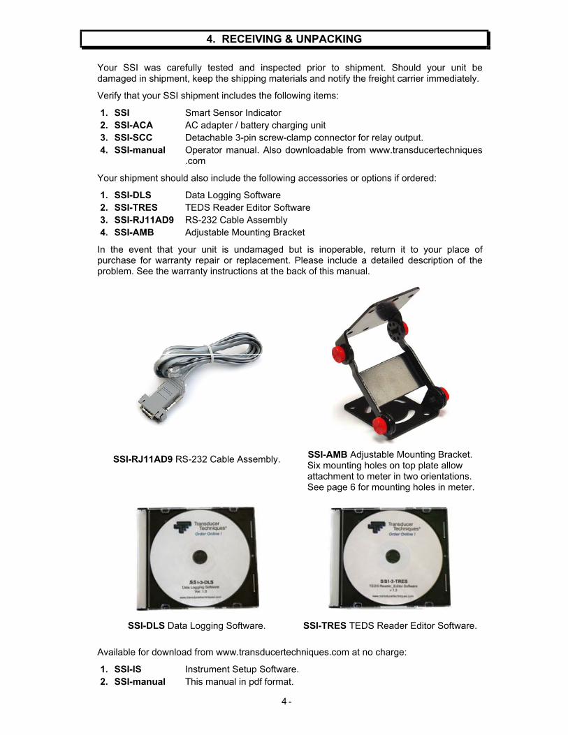
Verify that your SSI shipment includes the following items:
1. SSI Smart Sensor Indicator 2. SSI-ACA AC adapter / battery charging unit 3. SSI-SCC Detachable 3-pin screw-clamp connector for relay output. 4. SSI-manual Operator manual. Also downloadable from www.transducertechniques
.com
Your shipment should also include the following accessories or options if ordered:
1. SSI-DLS Data Logging Software 2. SSI-TRES TEDS Reader Editor Software 3. SSI-RJ11AD9 RS-232 Cable Assembly 4. SSI-AMB Adjustable Mounting Bracket
In the event that your unit is undamaged but is inoperable, return it to your place of purchase for warranty repair or replacement. Please include a detailed description of the problem. See the warranty instructions at the back of this manual.
SSI-RJ11AD9 RS-232 Cable Assembly. SSI-AMB Adjustable Mounting Bracket. Six mounting holes on top plate allow attachment to meter in two orientations. See page 6 for mounting holes in meter.
SSI-DLS Data Logging Software. SSI-TRES TEDS Reader Editor Software.
Available for download from www.transducertechniques.com at no charge:
1. SSI-IS Instrument Setup Software. 2. SSI-manual This manual in pdf format.

- 5
5. SAFETY CONSIDERATIONS & CARE OF YOUR METER
The SSI is housed in a tough ABS case and is mechanically rugged. The LCD display is protected by a clear Lexan cover. The unit is powered by a rechargeable lithium-ion battery. There are no internal voltages higher than 5V. AC mains power is limited to the input side of a sealed, UL-rated, wall plug AC adapter / battery charger unit.
Warning: Use of this equipment in a manner other than specified may impair the pro-tection of the device and subject the user to a hazard. Visually inspect the unit for signs of damage. If the unit is damaged, do not attempt to operate.
Safety Considerations
• For AC operation or charging, only use the designated AC adapter, P/N SSI-ACA.
• Do not plug the AC adapter into an electrical outlet other than 100-240V ac, 50/60 Hz.
• Do not plug the AC adapter into an electrical outlet if the unit is wet or has been damaged, as this could lead to electrical shock and/or equipment damage.
• Do not operate the instrument in the presence of flammable gases or fumes, as such an environment constitutes an explosion hazard.
• Do not operate the instrument if water can get inside the case.
• Do not apply signals to the inputs and outputs other than those specified in this manual.
• Do not operate this equipment without having studied this manual.
Equipment Care
• To maximize battery life, store your meter at room temperature. Avoid storage tempe-ratures below -20°C or above +55°C, as could be found in a parked vehicle.
• Do not drop the instrument. Avoid excessive shock or vibration, which could cause mecha-nical damage.
• Do not clean the meter with solvents. Instead, use a soft, damp cloth.
• Do not allow water or other fluid into the meter.
• Store the meter in its carrying case when not in use.
• For greatest accuracy, operate the meter at around 25°C, not at temperature extremes.
Symbols used
Caution (refer to accompanying documents)
Earth (ground) terminal.
Caution, risk of electric shock. Both direct and alternating current.
Equipment protected throughout by double insulation or reinforced insulation.
Operating environment:
The meter is Class II (double insulated) equipment designed for use in Pollution degree 2.
- 6
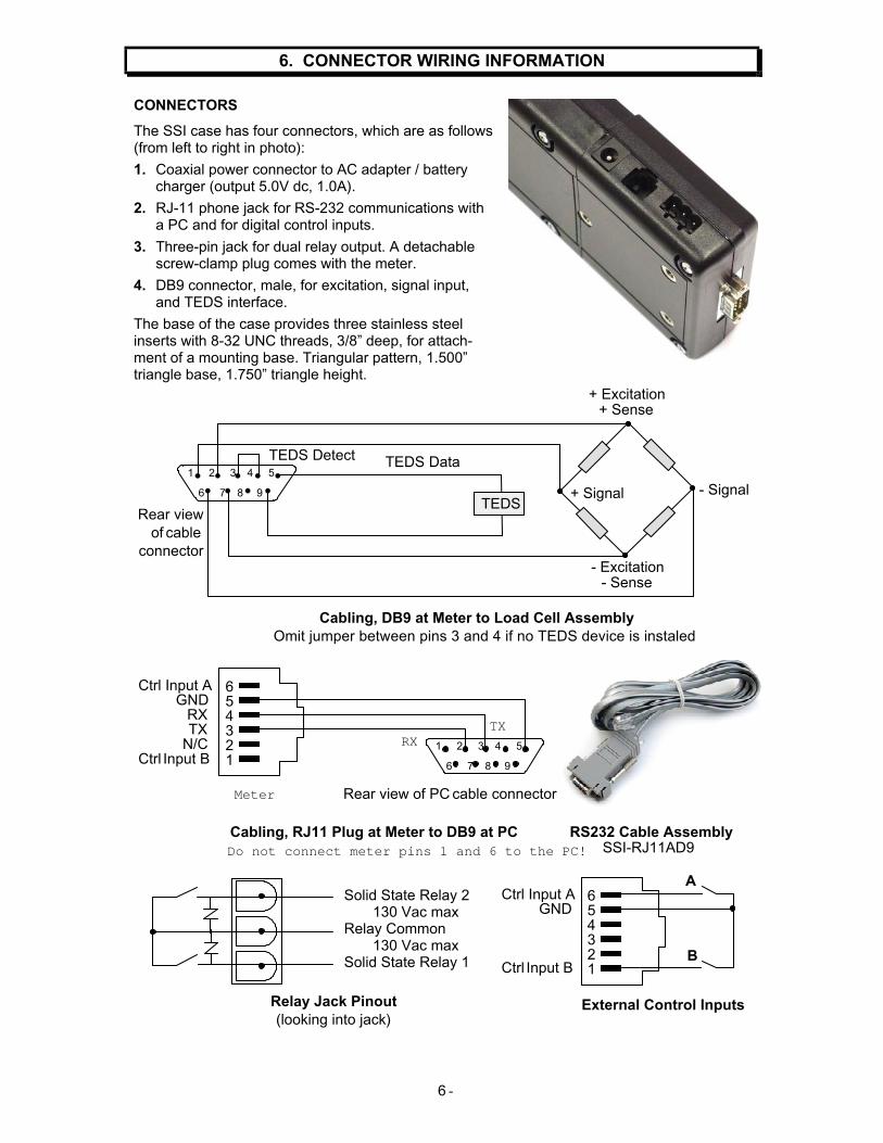
6. CONNECTOR WIRING INFORMATION
CONNECTORS
The SSI case has four connectors, which are as follows (from left to right in photo):
1. Coaxial power connector to AC adapter / battery charger (output 5.0V dc, 1.0A).
2. RJ-11 phone jack for RS-232 communications with a PC and for digital control inputs.
3. Three-pin jack for dual relay output. A detachable screw-clamp plug comes with the meter.
4. DB9 connector, male, for excitation, signal input, and TEDS interface.
The base of the case provides three stainless steel inserts with 8-32 UNC threads, 3/8” deep, for attach-ment of a mounting base. Triangular pattern, 1.500” triangle base, 1.750” triangle height.
Cabling, DB9 at Meter to Load Cell Assembly Omit jumper between pins 3 and 4 if no TEDS device is instaled.
654321
Ctrl Input AGND
RXTX
N/CCtrl Input B
1 2 3 4 5
6 7 8 9
TEDS Data
+ Excitation+ Sense
+ Signal - Signal
- Excitation- Sense
Rear view of cable
connector
1 2 3 4 5
6 7 8 9
Cabling, RJ11 Plug at Meter to DB9 at PCDo not connect meter pins 1 and 6 to the PC!
Solid State Relay 2 130 Vac maxRelay Common 130 Vac maxSolid State Relay 1
Relay Jack Pinout(looking into jack)
RS232 Cable AssemblySSI-RJ11AD9
TEDS Detect
Meter
RXTX
Rear view of PC cable connector
TEDS
654321
A
B
External Control Inputs
Ctrl Input AGND
Ctrl Input B
- 7
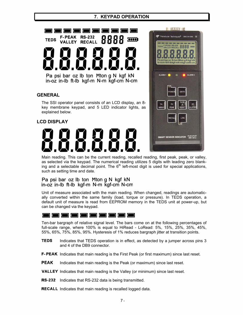
7. KEYPAD OPERATION
GENERAL
The SSI operator panel consists of an LCD display, an 8-key membrane keypad, and 5 LED indicator lights, as explained below.
LCD DISPLAY
Main reading. This can be the current reading, recalled reading, first peak, peak, or valley, as selected via the keypad. The numerical reading utilizes 5 digits with leading zero blank-ing and a selectable decimal point. The 6th left-most digit is used for special applications, such as setting time and date.
Unit of measure associated with the main reading. When changed, readings are automatic-ally converted within the same family (load, torque or pressure). In TEDS operation, a default unit of measure is read from EEPROM memory in the TEDS unit at power-up, but can be changed via the keypad.
Ten-bar bargraph of relative signal level. The bars come on at the following percentages of full-scale range, where 100% is equal to HiRead - LoRead: 5%, 15%, 25%, 35%, 45%, 55%, 65%, 75%, 85%, 95%. Hysteresis of 1% reduces bargraph jitter at transition points.
Indicates that TEDS operation is in effect, as detected by a jumper across pins 3 and 4 of the DB9 connector.
Indicates that main reading is the First Peak (or first maximum) since last reset.
Indicates that main reading is the Peak (or maximum) since last reset.
Indicates that main reading is the Valley (or minimum) since last reset.
Indicates that RS-232 data is being transmitted.
Indicates that main reading is recalled logged data.
- 8
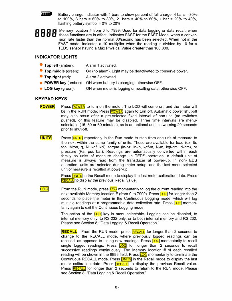
Battery charge indicator with 4 bars to show percent of full charge. 4 bars = 80% to 100%, 3 bars = 60% to 80%, 2 bars = 40% to 60%, 1 bar = 20% to 40%, flashing battery symbol = 0% to 20%.
Memory location # from 0 to 7999. Used for data logging or data recall, when these functions are in effect. Indicates FAST for the FAST Mode, when a conver-sion rate faster than the normal 60/second has been selected. When not in the FAST mode, indicates a 10 multiplier when the reading is divided by 10 for a TEDS sensor having a Max Physical Value greater than 100,000.
INDICATOR LIGHTS
• Top left (amber): Alarm 1 activated. • Top middle (green): Go (no alarm). Light may be deactivated to conserve power. • Top right (red): Alarm 2 activated.
POWER key (amber): ON when battery is charging, otherwise OFF.
LOG key (green): ON when meter is logging or recalling data, otherwise OFF.
KEYPAD KEYS
POWER Press POWER to turn on the meter. The LCD will come on, and the meter will be in the RUN mode. Press POWER again to turn off. Automatic power shut-off may also occur after a pre-selected fixed interval of non-use (no switches pushed), or this feature may be disabled. Three time intervals are menu-selectable (15, 30 or 60 minutes), as is an optional audible warning 20 seconds prior to shut-off.
UNITS Press UNITS repeatedly in the Run mode to step from one unit of measure to the next within the same family of units. These are available for load (oz, lb, ton, Mton, g, N, kgf, kN), torque (in-oz, in-lb, kgf-m, N-m, kgf-cm, N-cm), or pressure (Pa, psi, bar). Readings are automatically converted within each family as units of measure change. In TEDS operation, a default unit of measure is always read from the transducer at power-up. In non-TEDS operation, units are selected during meter setup, and the last menu-selected unit of measure is recalled at power-up.
Press UNITS in the Recall mode to display the last meter calibration date. Press RECALL to display the previous Recall value.
LOG From the RUN mode, press LOG momentarily to log the current reading into the next available Memory location # (from 0 to 7999). Press LOG for longer than 2 seconds to place the meter in the Continuous Logging mode, which will log multiple readings at a programmable data collection rate. Press LOG momen-tarily again to exit the Continuous Logging mode.
The action of the LOG key is menu-selectable. Logging can be disabled, to internal memory only, to RS-232 only, or to both internal memory and RS-232. Please see Section 8, “Data Logging & Recall Operation.”
RECALL From the RUN mode, press RECALL for longer than 2 seconds to change to the RECALL mode, where previously logged readings can be recalled, as opposed to taking new readings. Press LOG momentarily to recall single logged readings. Press LOG for longer than 2 seconds to recall successive readings continuously. The Memory location # of each recalled reading will be shown in the 8888 field. Press LOG momentarily to terminate the Continuous RECALL mode. Press UNITS in the Recall mode to display the last meter calibration date. Press RECALL to display the previous Recall value. Press RECALL for longer than 2 seconds to return to the RUN mode. Please see Section 8, “Data Logging & Recall Operation.”
- 9
> MENU From the RUN mode, Press > MENU to change to the Menu mode, which allows setting up the meter from the keypad. Press > MENU to step through menu items. Press > PEAK to select digits or sub-items within the selected menu item, and press TARE ^ RESET to modify the selected flashing digit or sub-item. The UNITS, RECALL and LOG keys are disabled in the Menu mode. Please see the Menu Mode section of this manual.
The > MENU and < ALARMS keys are also used in the RECALL mode to incre-ment or decrement Memory location #’s (from 0 to 7999) for displaying logged readings.
> PEAK The action of the > PEAK key is programmable to 4 operating modes, so that pressing it from the RUN mode will display 1) Peak, 2) First Peak, 3) Valley, 4) Peak (1st push) and Valley (2nd push). When Peak, Valley or First Peak is being displayed, the appropriate LCD indicator caption will be displayed (PEAK, VALLEY or F-PEAK). Pressing the > PEAK key one more time returns to the RUN mode.
The > PEAK key is also used in the Menu mode to advance the flashing indicator of the menu value, and in the RECALL mode to advance the next flashing digit of the logging Memory location # (0 to 7999).
TARE ^ RESET
To zero the display from the RUN mode, press TARE ^ RESET (selectable Tare function). With no load applied, this action will zero the system. If the meter is used in a weighing application with an empty container, this will subtract the weight of the empty container to display net weight.
To reset the meter, hold the TARE ^ RESET key depressed while you press and release the > MENU key.
To reset a Peak, Valley or First Peak, hold the TARE ^ RESET key depressed while you press and release the > PEAK key.
To reset latched Alarms, hold the TARE ^ RESET key depressed while you press and release the < ALARMS key.
The TARE ^ RESET key is also used in the Menu mode and in the RECALL mode to increment the flashing selection.
< ALARMS From the RUN mode, press < ALARMS to change to the Alarms mode, which allows viewing and changing setpoints from the keypad. Press once to view Setpoint 1. The Alarm 1 indicator (amber LED) will light. Press again to view Setpoint 2. The Alarm 2 indicator (red LED) will light. Press again to exit the Alarms mode and return to the RUN mode. While the Alarm 1 indicator is lit, you can change Setpoint 1 by pressing > PEAK to select a digit, which will flash, then pressing TARE ^ RESET to increment that digit. Same for Setpoint 2.
In the Menu mode, the > ALARMS key steps backward through the menu. In the RECALL mode, it is used to decrement Memory location #’s from 7999 to 0.
TEDS ERROR MESSAGES
If there is a problem with the TEDS connection between the meter and TEDS transducer, one of the following error messages is displayed at power on:
Err 1 - TEDS data line shorted. Err 2 - No Presence pulse from TEDS. Err 3 - Improper Presence pulse width. Err 4 - Error in TEDS family code in ROM. Err 5 - TEDS checksum error in the first or second 32 bytes.
Correct the problem and then press the Menu key.
- 10
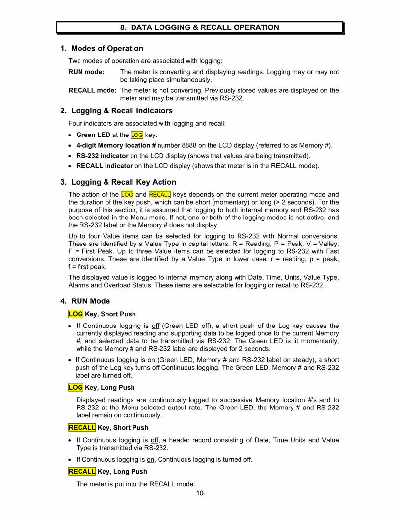
8. DATA LOGGING & RECALL OPERATION
1. Modes of Operation
Two modes of operation are associated with logging:
RUN mode: The meter is converting and displaying readings. Logging may or may not be taking place simultaneously.
RECALL mode: The meter is not converting. Previously stored values are displayed on the meter and may be transmitted via RS-232.
2. Logging & Recall Indicators
Four indicators are associated with logging and recall:
• Green LED at the LOG key.
• 4-digit Memory location # number 8888 on the LCD display (referred to as Memory #).
• RS-232 indicator on the LCD display (shows that values are being transmitted).
• RECALL indicator on the LCD display (shows that meter is in the RECALL mode). 3. Logging & Recall Key Action
The action of the LOG and RECALL keys depends on the current meter operating mode and the duration of the key push, which can be short (momentary) or long (> 2 seconds). For the purpose of this section, it is assumed that logging to both internal memory and RS-232 has been selected in the Menu mode. If not, one or both of the logging modes is not active, and the RS-232 label or the Memory # does not display.
Up to four Value items can be selected for logging to RS-232 with Normal conversions. These are identified by a Value Type in capital letters: R = Reading, P = Peak, V = Valley, F = First Peak. Up to three Value items can be selected for logging to RS-232 with Fast conversions. These are identified by a Value Type in lower case: r = reading, p = peak, f = first peak.
The displayed value is logged to internal memory along with Date, Time, Units, Value Type, Alarms and Overload Status. These items are selectable for logging or recall to RS-232.
4. RUN Mode
LOG Key, Short Push
• If Continuous logging is off (Green LED off), a short push of the Log key causes the currently displayed reading and supporting data to be logged once to the current Memory #, and selected data to be transmitted via RS-232. The Green LED is lit momentarily, while the Memory # and RS-232 label are displayed for 2 seconds.
• If Continuous logging is on (Green LED, Memory # and RS-232 label on steady), a short push of the Log key turns off Continuous logging. The Green LED, Memory # and RS-232 label are turned off.
LOG Key, Long Push
Displayed readings are continuously logged to successive Memory location #’s and to RS-232 at the Menu-selected output rate. The Green LED, the Memory # and RS-232 label remain on continuously.
RECALL Key, Short Push
• If Continuous logging is off, a header record consisting of Date, Time Units and Value Type is transmitted via RS-232.
• If Continuous logging is on, Continuous logging is turned off.
RECALL Key, Long Push
The meter is put into the RECALL mode.

- 11
5. Recall Mode
A Long push of the RECALL key enters the RECALL mode from the RUN mode, and the RECALL label is displayed. The meter no longer takes new readings, but recalls previously stored readings from memory. The Memory # is shown on the 4-digit (8888) display and the value stored at that location is shown on the 6-digit main display. If RS-232 has been selected, the RS-232 label is displayed.
Manual Controls to Change Memory #
Press > MENU to increment the Memory # displayed.
Press < ALARMS to decrement the Memory # displayed.
To set the Memory # directly to a value:
1. Press > PEAK to advance to the next digit of the Memory #. That digit will flash.
2. Press TARE ^ RESET to increment the flashing digit.
When done, press > MENU to save the changed Memory #.
When exiting the RECALL mode and reentering the RUN mode, the next logged data is to the last Memory # being displayed, unless Memory Protect is enabled, in which case the next logged data is to the next Memory # after the highest Memory # with stored data.
The RECALL mode can also be initiated by computer. The main display then shows dnLoAd. When this mode is entered, the computer-selected Memory #’s are displayed and transmitted via RS-232 to the computer. When done, the meter is reset to the RUN mode.
LOG Key, Short Push
• If Continuous Recall is off (Green LED off): Transmits the displayed value and all other selected non-value data items over RS-232. Advances the Memory # and displays that stored value.
• If Continuous Recall is on (Green LED on): Turns Continuous Recall and the Green LED off. The current Memory # and RS-232 label remain on steady.
LOG Key, Long Push
Transmits the displayed Value and selected non-value data items over RS-232, then advances the Memory #. This is repeated continuously until the LOG or RECALL key is given a Short push to turn off Continuous Recall. The Green LED, Memory # and RS-232 label remain on during continuous transmission.
RECALL Key, Short Push
• If Continuous Recall is off (Green LED off): No effect.
• If Continuous recall is on (Green LED on steady): Continuous Recall and the green LED are turned off.
RECALL Key, Long Push
Returns the meter to the RUN mode.
Summary of Key Operations
RECALL Key, Long Push: Toggles between the RUN mode and the RECALL mode.
LOG Key, Short Push: Causes one log or one recall if not in Continuous logging or recall, else turns off continuous logging or recall.
LOG Key, Long Push: Enters Continuous Log or Recall
RECALL Key, Short Push: Sends Header in RUN mode if not in Continuous logging, otherwise turns off Continuous logging or recall.
- 12
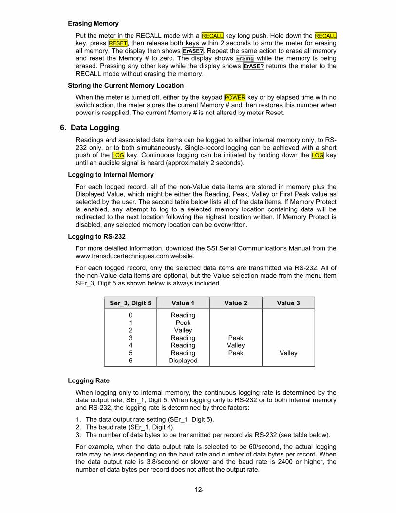
Erasing Memory
Put the meter in the RECALL mode with a RECALL key long push. Hold down the RECALL key, press RESET, then release both keys within 2 seconds to arm the meter for erasing all memory. The display then shows ErASE?. Repeat the same action to erase all memory and reset the Memory # to zero. The display shows ErSing while the memory is being erased. Pressing any other key while the display shows ErASE? returns the meter to the RECALL mode without erasing the memory.
Storing the Current Memory Location
When the meter is turned off, either by the keypad POWER key or by elapsed time with no switch action, the meter stores the current Memory # and then restores this number when power is reapplied. The current Memory # is not altered by meter Reset.
6. Data Logging
Readings and associated data items can be logged to either internal memory only, to RS-232 only, or to both simultaneously. Single-record logging can be achieved with a short push of the LOG key. Continuous logging can be initiated by holding down the LOG key until an audible signal is heard (approximately 2 seconds).
Logging to Internal Memory
For each logged record, all of the non-Value data items are stored in memory plus the Displayed Value, which might be either the Reading, Peak, Valley or First Peak value as selected by the user. The second table below lists all of the data items. If Memory Protect is enabled, any attempt to log to a selected memory location containing data will be redirected to the next location following the highest location written. If Memory Protect is disabled, any selected memory location can be overwritten.
Logging to RS-232
For more detailed information, download the SSI Serial Communications Manual from the www.transducertechniques.com website.
For each logged record, only the selected data items are transmitted via RS-232. All of the non-Value data items are optional, but the Value selection made from the menu item SEr_3, Digit 5 as shown below is always included.
Ser_3, Digit 5 Value 1 Value 2 Value 3
0 1 2 3 4 5 6
Reading Peak Valley
Reading Reading Reading
Displayed
Peak Valley Peak
Valley
Logging Rate
When logging only to internal memory, the continuous logging rate is determined by the data output rate, SEr_1, Digit 5. When logging only to RS-232 or to both internal memory and RS-232, the logging rate is determined by three factors:
1. The data output rate setting (SEr_1, Digit 5). 2. The baud rate (SEr_1, Digit 4). 3. The number of data bytes to be transmitted per record via RS-232 (see table below).
For example, when the data output rate is selected to be 60/second, the actual logging rate may be less depending on the baud rate and number of data bytes per record. When the data output rate is 3.8/second or slower and the baud rate is 2400 or higher, the number of data bytes per record does not affect the output rate.
- 13
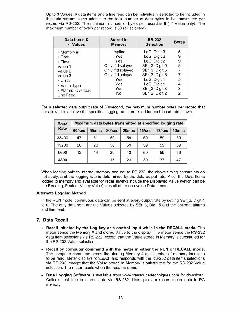
Up to 3 Values, 6 data items and a line feed can be individually selected to be included in the data stream, each adding to the total number of data bytes to be transmitted per record via RS-232. The minimum number of bytes per record is 8 (1st Value only). The maximum number of bytes per record is 59 (all selected).
Data Items & ∗ Values
Stored in Memory
RS-232 Selection
Bytes
∗ Memory # ∗ Date ∗ Time Value 1 Value 2 Value 3 ∗ Units ∗ Value Type ∗ Alarms, Overload Line Feed
Implied Yes Yes
Only if displayed Only if displayed Only if displayed
Yes Yes Yes No
LoG, Digit 3 LoG, Digit 2 LoG, Digit 2
SEr_3, Digit 5 SEr_3, Digit 5 SEr_3, Digit 5 LoG, Digit 1 LoG, Digit 1
SEr_2, Digit 3 SEr_2, Digit 2
5 9 9 8 7 7 5 4 3 2
For a selected data output rate of 60/second, the maximum number bytes per record that are allowed to achieve the specified logging rates are listed for each baud rate shown:
Maximum data bytes transmitted at specified logging rate Baud Rate 60/sec 55/sec 30/sec 20/sec 15/sec 12/sec 10/sec
38400 47 51 59 59 59 59 59
19200 26 26 56 59 59 59 59
9600 12 14 29 43 59 59 59
4800 15 23 30 37 47
When logging only to internal memory and not to RS-232, the above timing constraints do not apply, and the logging rate is determined by the data output rate. Also, the Data Items logged to memory and available for recall always include the Displayed Value (which can be the Reading, Peak or Valley Value) plus all other non-value Data Items.
Alternate Logging Method
In the RUN mode, continuous data can be sent at every output rate by setting SEr_2, Digit 4 to 0. The only data sent are the Values selected by SEr_3, Digit 5 and the optional alarms and line feed.
7. Data Recall
• Recall initiated by the Log key or a control input while in the RECALL mode. The meter sends the Memory # and stored Value to the display. The meter sends the RS-232 data item selections via RS-232, except that the Value stored in Memory is substituted for the RS-232 Value selection.
• Recall by computer command with the meter in either the RUN or RECALL mode. The computer command sends the starting Memory # and number of memory locations to be read. Meter displays “dnLoAd” and responds with the RS-232 data items selections via RS-232, except that the Value stored in Memory is substituted for the RS-232 Value selection. The meter resets when the recall is done.
• Data Logging Software is available from www.transducertechniques.com for download. Collects real-time or stored data via RS-232. Lists, plots or stores meter data in PC memory.
- 14
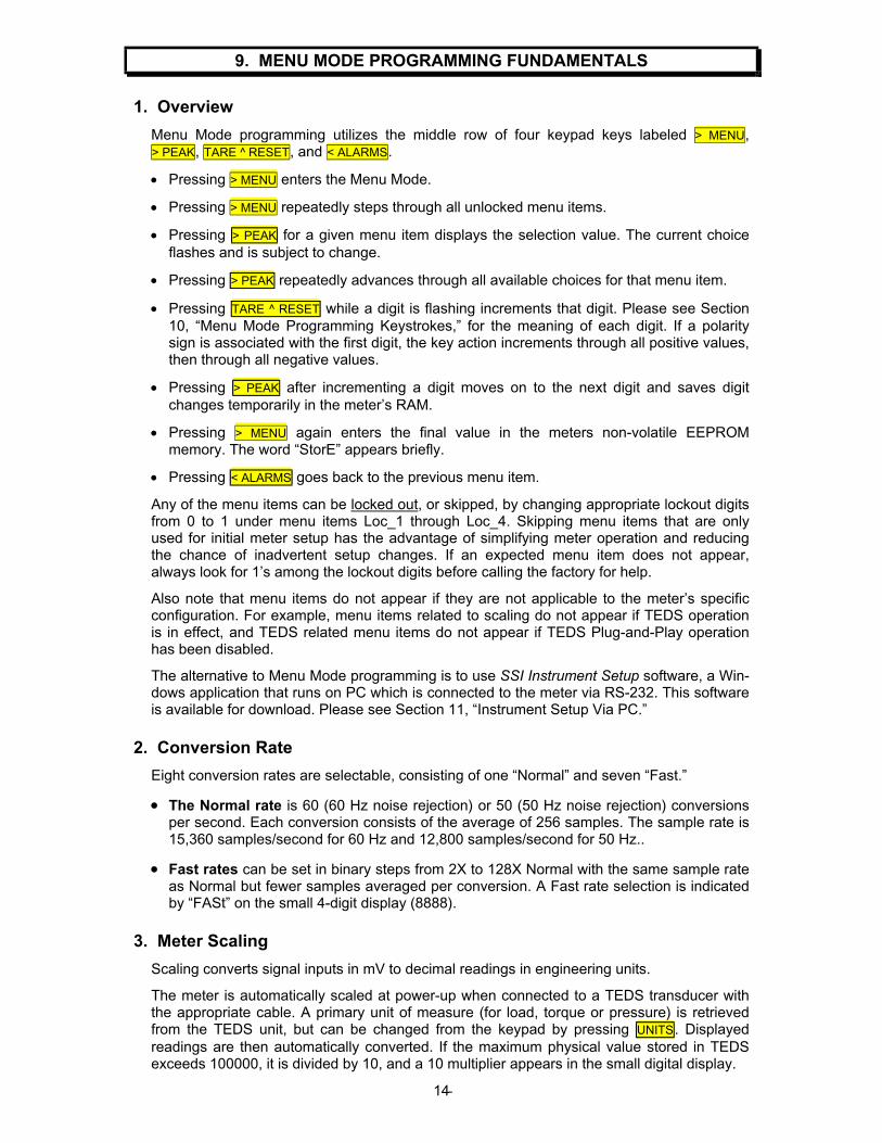
9. MENU MODE PROGRAMMING FUNDAMENTALS
1. Overview
Menu Mode programming utilizes the middle row of four keypad keys labeled > MENU, > PEAK, TARE ^ RESET, and < ALARMS.
• Pressing > MENU enters the Menu Mode.
• Pressing > MENU repeatedly steps through all unlocked menu items.
• Pressing > PEAK for a given menu item displays the selection value. The current choice flashes and is subject to change.
• Pressing > PEAK repeatedly advances through all available choices for that menu item.
• Pressing TARE ^ RESET while a digit is flashing increments that digit. Please see Section 10, “Menu Mode Programming Keystrokes,” for the meaning of each digit. If a polarity sign is associated with the first digit, the key action increments through all positive values, then through all negative values.
• Pressing > PEAK after incrementing a digit moves on to the next digit and saves digit changes temporarily in the meter’s RAM.
• Pressing > MENU again enters the final value in the meters non-volatile EEPROM memory. The word “StorE” appears briefly.
• Pressing < ALARMS goes back to the previous menu item.
Any of the menu items can be locked out, or skipped, by changing appropriate lockout digits from 0 to 1 under menu items Loc_1 through Loc_4. Skipping menu items that are only used for initial meter setup has the advantage of simplifying meter operation and reducing the chance of inadvertent setup changes. If an expected menu item does not appear, always look for 1’s among the lockout digits before calling the factory for help.
Also note that menu items do not appear if they are not applicable to the meter’s specific configuration. For example, menu items related to scaling do not appear if TEDS operation is in effect, and TEDS related menu items do not appear if TEDS Plug-and-Play operation has been disabled.
The alternative to Menu Mode programming is to use SSI Instrument Setup software, a Win-dows application that runs on PC which is connected to the meter via RS-232. This software is available for download. Please see Section 11, “Instrument Setup Via PC.”
2. Conversion Rate
Eight conversion rates are selectable, consisting of one “Normal” and seven “Fast.”
• The Normal rate is 60 (60 Hz noise rejection) or 50 (50 Hz noise rejection) conversions per second. Each conversion consists of the average of 256 samples. The sample rate is 15,360 samples/second for 60 Hz and 12,800 samples/second for 50 Hz..
• Fast rates can be set in binary steps from 2X to 128X Normal with the same sample rate as Normal but fewer samples averaged per conversion. A Fast rate selection is indicated by “FASt” on the small 4-digit display (8888).
3. Meter Scaling
Scaling converts signal inputs in mV to decimal readings in engineering units.
The meter is automatically scaled at power-up when connected to a TEDS transducer with the appropriate cable. A primary unit of measure (for load, torque or pressure) is retrieved from the TEDS unit, but can be changed from the keypad by pressing UNITS. Displayed readings are then automatically converted. If the maximum physical value stored in TEDS exceeds 100000, it is divided by 10, and a 10 multiplier appears in the small digital display.
- 15
Two scaling methods are selectable under SEtuP for non-TEDS transducers:
The “Coordinates of 2 Points” scaling method can be used with non-TEDS transducers when physical input signals are not available. With this method, (Lo in, Lo rd) and (Hi in, Hi rd) data points are entered numerically and appear near the middle of the menu items.
The “Reading Coordinates of 2 Points” scaling method can be used with non-TEDS transducers when actual input signals are available. This method has the advantage of scaling the load cell and meter as a system, and voltage values do not need to be known. An actual “Lo in” signal, such as the output of a load cell at zero load, and “Hi in” signal, such as the output of the same load cell at a known high load, are applied to the meter. The desired corresponding Lo Rd, Hi Rd and HiEnd values are entered from the keypad. The HiEnd value is the high end reading of the span over which the load cell is expected to operate. The display will flash overload when the reading reaches the High End value +20% of span (HiEnd - Lo Rd). If this scaling method is selected, the six related menu items, which include selection of the unit of measure, will appear ahead of all other menu items.
4. Decimal Point Selection
The decimal point is user selectable under dEC.Pt, but acts differently in TEDS and non-TEDS operation. In TEDS operation, it relates to the reading. For example, the same weight reading in grams can be displayed in integer grams only or be followed by one, two or three decimals. In non-TEDS operation, the decimal point is independent of the numerical reading in counts, so that the reading can be in different units. For example, by moving the decimal point from left to right, the same weight could be displayed with the same resolution and accuracy in hectograms, decagrams, grams, decigrams, centigrams or milligrams. If TEDS is connected and Plug & Play is enabled, the decimal point is obtained from TEDS and not the meter. The meter displays tEdS instead of StorE for a stored change.
5. Noise Filtering
Since electrical noise is often a factor with millivolt signals, the SSI offers programmable features so that a user can make the best compromise between noise rejection and meter response rate for the application and noise environment.
NOTE: Noise filtering is only available at Normal conversion rates of 60 or 50 Hz.
The first selection under the SEtuP menu item is for 60 or 50 Hz noise environments. This sets the basic conversion rate of the meter to a full line cycle at 60 or 50 Hz, so as to cancel out the positive and negative components of AC line noise pickup for any conversion.
A value called “filtered value” is listed under the FiLtr menu item. This value can then be assigned to the Displayed reading and hence logged reading, to Alarms, and to Peak & Valley. Choices for the filtered value are the following:
• Batch average of 16 conversions. The filtered values are independent of each other and are updated every 267 ms (60 Hz) or 320 ms (50 Hz).
• Moving average filter. The equivalent RC time constants are listed in Section 10, FiLtr, Digit 5. Regardless of the filter method, the meter display is always updated every 16 conversions (3.75 times/second at 60 Hz, 3.125 times/second at 50 Hz) because this is a good update rate for the human eye.
• Autofilter moving average filter. In this mode, the meter automatically selects the best moving average time constant for the encountered noise condition.
Adaptive filter operation is always functional with moving average filters. This means that the filter automatically resets the moving average to the current reading when a significant step in the signal is encountered. With adaptive filtering, the meter can respond rapidly to meaningful changes in signal level, while filtering out random noise. Two adaptive filter thresholds are selectable: Low and High. Low should normally be selected, while High should be selected if high noise transients are expected.
Zero setting (ZEro menu item) can set the meter reading to zero when the signal level is below a specified percentage of full scale. This avoids meaningless noise readings when the reading should be zero.
- 16
6. Peak, Valley, First Peak, Fast Peak
With the Normal conversion rate, as set up under the SEtuP menu item, Peak, Valley and First Peak can be based on the Filtered or Unfiltered value, as selected under the FiLtr menu. The displayed reading in response to pressing the > PEAK key then can be Peak, First Peak, Valley, or Peak (1st push) and Valley (2nd push), as selected under the ConFG menu. Any combination of the current Reading, Peak/First Peak or Valley can be data logged to a computer via RS-232 along with time and date, as selected under the SEr_3 menu. However, the displayed reading is the only time and date tagged item logged to internal memory.
With a Fast conversion rate, as set up under the SEtuP menu, the much faster Fast Peak and First Peak capture modes apply, and all filtering is disabled. When the 128 x Normal conversion rate is selected, the meter can capture Fast Peaks as fast as every 130 �s. Polarity of the Fast Peak is pre-selected to be positive or negative under the ConFG menu.
Reset for all Peak and Valley related items is achieved by holding the TARE ^ RESET key depressed while momentarily pressing > PEAK.
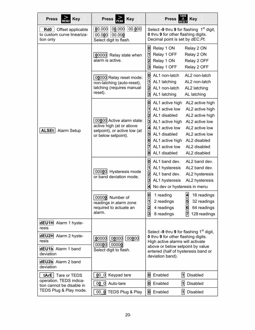
7. Alarms
The SSI includes two solid state alarm relays rated 110 mA @ 350V peak, 35 ohms series resistance. There is a common contact for the two relays. The active state of alarms is shown by LED indicators: amber for Alarm 1, red for Alarm 2, and green for “Go” with no alarm active. The “Go” LED can be disabled under the ALErt menu to conserve power.
With the Normal conversion rate, the relays can respond to the Unfiltered or Filtered value, as selected under the FiLtr menu, to avoid triggering on electrical noise. The number of consecutive readings in the alarm zone required to actuate the alarm is selectable in binary steps from 1 to 128 (ALSet menu item) to avoid actuating on transients.
The action of the two relays is individually programmable with the ALSet menu item. Each relay can be set to ON or OFF when the corresponding alarm is active, to be latching or non-latching, to activate above or below the setpoint, and to operate with hysteresis or band deviation.
• Hysteresis, set under the dEU1H and dEU2H menus, controls alarm action symmetric-ally around a setpoint. A high active alarm activates when the reading goes above the setpoint by the hysteresis value and de-activates when the reading falls below the setpoint by the hysteresis value. A narrow hysteresis band can be used to minimize relay chatter around a setpoint due to electrical noise or signal feedback caused by load switching. A wide hysteresis band can be used for control applications. The hysteresis band is twice the hysteresis value.
• Band deviation, set under the dEU1b and dEU2b menus, controls alarm action sym-metrically around a setpoint to create a passband. A high active alarm activates when the reading falls outside the deviation band, and de-activates when the reading falls inside. A deviation value is set up around both sides of the setpoint to create a pass band. Band deviation is often used in QA applications to pass or reject parts. The deviation band equals twice the deviation value.
8. Keypad Lockouts
Many of the menu items can be locked out, or skipped, by changing appropriate lockout digits from 0 to 1 under menu items Loc_1 through Loc_4. Skipping menu items that are only used for initial meter setup has the advantage of simplifying meter operation and reducing the chance of inadvertent setup changes. If an expected menu item does not appear, always look for 1’s among the lockout digits before calling the factory for help!
9. External Control Inputs
By shorting one or both control inputs A and B to ground (see Section 6), the following items can be externally commanded: log, tare, tare reset, Peak, Valley, Peak then Valley, function reset, meter reset. These functions are also available from the keypad unless locked out.
- 17
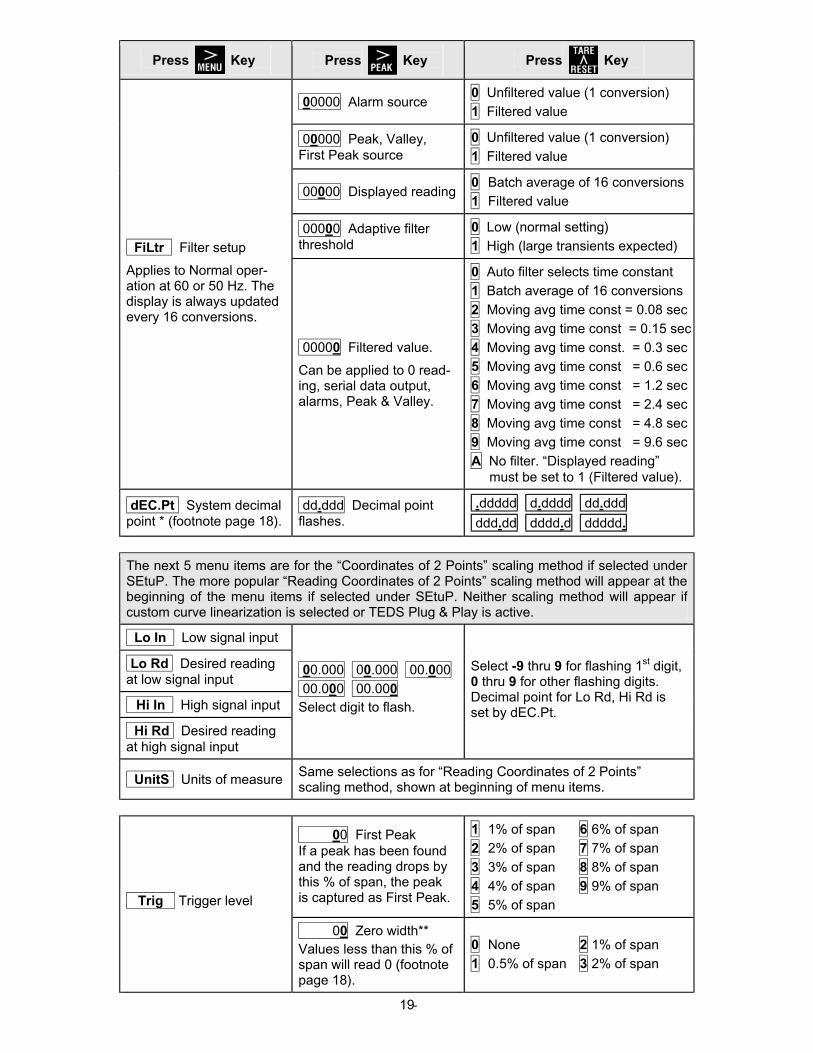
10. MENU MODE PROGRAMMING KEYSTROKES
The five menu items on this page will appear first when the > MENU key is first pressed from the RUN mode if the following conditions apply:
1. The transducer is a non-TEDS transducer or a TEDS transducer where Plug & Play operation has been disabled.
2. The “Reading Coordinates of 2 Points” scaling method has been selected under SEtuP.
3. Custom curve linearization has not been selected.
4. If a menu item does not appear, please see “Keypad Lockouts” in Section 9 and the Loc_1 to Loc_4 digit details at the end of the current section.
EXAMPLE FOR A 0-100 LB LOAD CELL AT 2 mV/V CALIBRATED AT 50 LBS
Press Key
Press
Key
Press
Key
Lo In Apply low signal input (e.g., load cell output for 0.00 lbs).
0.02 Press to dis-play reading at low signal input.
0.02 Press to store low reading.
Hi In Apply high signal input (e.g., load cell output for known 50.00 lbs).
3.03 Press to dis-play reading at high signal input.
3.03 Press to store high reading.
Lo rd Enter desired reading at low signal input (e.g., 0.00).
000.00 000.00 000.00
000.00 000.00 Select digit to flash.
0.00 Select -9 thru 9 for flashing 1st digit, 0 thru 9 for other flashing digits.
Hi rd Enter desired reading at high signal input (e.g., 50.00).
000.00 000.00 000.00
000.00 000.00 Select digit to flash.
50.00 Select -9 thru 9 for flashing 1st digit, 0 thru 9 for other flashing digits.
HiEnd Enter desired reading for high end of span (e.g., 100.00).
000.00 000.00 000.00
000.00 000.00 Select digit to flash.
100.00 Select -9 thru 9 for flashing 1st digit, 0 thru 9 for other flashing digits.
none N No unit of measure
LoAd Units of load
oz Ounce lb Pound
ton U.S. ton (2,000 lbs)
Mton Metric ton (2,204.62 lbs)
g Gram N Newton
kgf Kilogram
kN KiloNewton
torque Units of torque
In-oz Inch-ounce
In-lb Inch-pound
ft-lb Foot-pound
kgf-m Kilogram-meter
N-m Newton-meter
kgf-cm Kilogram-centimeter
N-cm Newton-centimeter
UnitS Select unit of measure.
PrESSr Units of pressure
Pa Pascal
psi Pounds per sq. inch
bar Bar
- 18
Press Key
Press
Key
Press
Key
0_00 Noise rejection 0 60 Hz environment
1 50 Hz environment
0_00 Scaling method
0 Not used
1 Coordinates of 2 points
2 Reading coordinates of 2 points
SEtuP First set of meter setup functions. 0_00 Action of external
control inputs A & B, or si-multaneous inputs A & B. * Display Peak or Valley as selected under ConFG. Funct Reset resets Peak, Valley & Latched Alarms.
Ctrl Input A Ctrl Input B Both 0 Meter reset Funct. reset Meter
1 Meter reset Pk or Vy* Meter
2 Meter reset Tare Meter
3 Meter reset Log Meter
4 Funct. reset Pk or Vy* Meter
5 Funct. reset Tare Meter
6 Funct. reset Log Meter
7 Pk or Vy* Tare Funct 8 Pk or Vy* Log Funct
9 Tare Log Funct
A Tare Tare reset Funct
B Valley Peak Funct
00000 Conversion rate
Rates are shown for 60 Hz environment. Divide by 1.2 for 50 Hz. See Section 15 (Specifications) for corresponding internal noise levels in µV.
0 60 conversions/sec (Normal rate)
1 120 conversion/sec (Fast rate)
2 240 conversion/sec (Fast rate)
3 480 conversion/sec (Fast rate)
4 960 conversion/sec (Fast rate)
5 1,920 conversion/sec (Fast rate)
6 3,840 conversion/sec (Fast rate)
7 7,680 conversion/sec (Fast rate)
00000 Displayed value in response to pressing the > PEAK key.
0 Peak (Normal or Fast rate)
1 First Peak (Normal or Fast rate)
2 Valley (Normal rate only)
3 Peak (1st push), Valley (2nd push) (Normal rate only)
00000 Peak polarity. Applies only to Fast con-version rates.
0 Positive Peak
1 Negative Peak
00000 Signal polarity 0 Normal
1 Reversed
ConFG Second set of meter setup functions.
00000 Custom curve linearization. Normal rate only.
0 Linear input
1 Custom curve
* If TEDS is connected and Plug & Play is enabled, the decimal point is obtained from TEDS
and not the meter. When changed, the meter displays tEdS instead of StorE .
** Select “None” for Zero Width if the zero reading occurs other than at one end of the measurement range.
- 19
Press Key
Press
Key
Press
Key
00000 Alarm source 0 Unfiltered value (1 conversion)
1 Filtered value
00000 Peak, Valley, First Peak source
0 Unfiltered value (1 conversion)
1 Filtered value
00000 Displayed reading 0 Batch average of 16 conversions
1 Filtered value
00000 Adaptive filter threshold
0 Low (normal setting)
1 High (large transients expected) FiLtr Filter setup
Applies to Normal oper-ation at 60 or 50 Hz. The display is always updated every 16 conversions.
00000 Filtered value.
Can be applied to 0 read-ing, serial data output, alarms, Peak & Valley.
0 Auto filter selects time constant
1 Batch average of 16 conversions
2 Moving avg time const = 0.08 sec
3 Moving avg time const = 0.15 sec
4 Moving avg time const. = 0.3 sec
5 Moving avg time const = 0.6 sec
6 Moving avg time const = 1.2 sec
7 Moving avg time const = 2.4 sec
8 Moving avg time const = 4.8 sec
9 Moving avg time const = 9.6 sec
A No filter. “Displayed reading” must be set to 1 (Filtered value).
dEC.Pt System decimal point * (footnote page 18).
dd.ddd Decimal point flashes.
.ddddd d.dddd dd.ddd llll
ddd.dd dddd.d ddddd. llll
The next 5 menu items are for the “Coordinates of 2 Points” scaling method if selected under SEtuP. The more popular “Reading Coordinates of 2 Points” scaling method will appear at the beginning of the menu items if selected under SEtuP. Neither scaling method will appear if custom curve linearization is selected or TEDS Plug & Play is active.
Lo In Low signal input
Lo Rd Desired reading at low signal input
Hi In High signal input
Hi Rd Desired reading at high signal input
00.000 00.000 00.000
00.000 00.000 Select digit to flash.
Select -9 thru 9 for flashing 1st digit, 0 thru 9 for other flashing digits. Decimal point for Lo Rd, Hi Rd is set by dEC.Pt.
UnitS Units of measure Same selections as for “Reading Coordinates of 2 Points” scaling method, shown at beginning of menu items.
00. First Peak If a peak has been found and the reading drops by this % of span, the peak is captured as First Peak.
1 1% of span 6 6% of span
2 2% of span 7 7% of span
3 3% of span 8 8% of span
4 4% of span 9 9% of span
5 5% of span Trig Trigger level
00. Zero width** Values less than this % of span will read 0 (footnote page 18).
0 None 2 1% of span
1 0.5% of span 3 2% of span
- 20
Press Key
Press
Key
Press
Key
Rd0 Offset applicable to custom curve lineariza-tion only
00.000 00.000 00.000
00.000 00.000 Select digit to flash.
Select -9 thru 9 for flashing 1st digit, 0 thru 9 for other flashing digits. Decimal point is set by dEC.Pt.
00000 Relay state when alarm is active.
0 Relay 1 ON Relay 2 ON
1 Relay 1 OFF Relay 2 ON
2 Relay 1 ON Relay 2 OFF
3 Relay 1 OFF Relay 2 OFF
00000 Relay reset mode: non-latching (auto-reset), latching (requires manual reset).
0 AL1 non-latch AL2 non-latch
1 AL1 latching AL2 non-latch
2 AL1 non-latch AL2 latching
3 AL1 latching AL latching
00000 Active alarm state: active high (at or above setpoint), or active low (at or below setpoint).
0 AL1 active high AL2 active high
1 AL1 active low AL2 active high
2 AL1 disabled AL2 active high
3 AL1 active high AL2 active low
4 AL1 active low AL2 active low
5 AL1 disabled AL2 active low
6 AL1 active high AL2 disabled
7 AL1 active low AL2 disabled
8 AL1 disabled AL2 disabled
00000 Hysteresis mode or band deviation mode.
0 AL1 band dev. AL2 band dev.
1 AL1 hysteresis AL2 band dev.
2 AL1 band dev. AL2 hysteresis
3 AL1 hysteresis AL2 hysteresis
4 No dev or hysteresis in menu
ALSEt Alarm Setup
00000 Number of readings in alarm zone required to actuate an alarm.
0 1 reading 4 16 readings
1 2 readings 5 32 readings
2 4 readings 6 64 readings
3 8 readings 7 128 readings
dEU1H Alarm 1 hyste-resis
dEU2H Alarm 2 hyste-resis
dEU1b Alarm 1 band deviation
dEU2b Alarm 2 band deviation
00000 00000 00000
00000 00000 Select digit to flash.
Select -9 thru 9 for flashing 1st digit, 0 thru 9 for other flashing digits. High active alarms will activate above or below setpoint by value entered (half of hysteresis band or deviation band).
00_0 Keypad tare 0 Enabled 1 Disabled
00_0 Auto-tare 0 Enabled 1 Disabled
tArE Tare or TEDS operation. TEDS indica-tion cannot be disable in TEDS Plug & Play mode. 00_0 TEDS Plug & Play 0 Enabled 1 Disabled
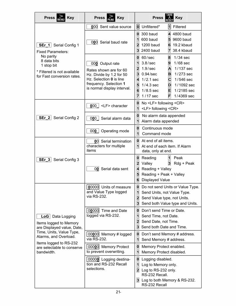
- 21
Press Key
Press
Key
Press
Key
000 Sent value source 0 Unfiltered* 1 Filtered
000 Serial baud rate
0 300 baud 4 4800 baud
1 600 baud 5 9600 baud
2 1200 baud 6 19.2 kbaud
3 2400 baud 7 38.4 kbaud SEr_1 Serial Config 1
Fixed Parameters: No parity 8 data bits 1 stop bit
* Filtered is not available for Fast conversion rates.
000 Output rate
Rates shown are for 60 Hz. Divide by 1.2 for 50 Hz. Selection 0 is line frequency. Selection 1 is normal display interval.
0 60 / sec 8 1 / 34 sec
1 3.8 / sec 9 1 / 68 sec
2 1.9 / sec A 1 / 137 sec
3 0.94 /sec B 1 / 273 sec
4 1 / 2.1 sec C 1 / 546 sec
5 1 / 4.3 sec D 1 / 1092 sec
6 1 / 8.5 sec E 1 / 2185 sec
7 1 / 17 sec F 1 / 4369 sec
000_ <LF> character 0 No <LF> following <CR>
1 <LF> following <CR>
000_ Serial alarm data 0 No alarm data appended
1 Alarm data appended SEr_2 Serial Config 2
000_ Operating mode 0 Continuous mode
1 Command mode
00 Serial termination characters for multiple items
0 At end of all items.
1 At end of each item. If Alarm data, only at end.
SEr_3 Serial Config 3
00 Serial data sent
0 Reading 1 Peak
2 Valley 3 Rdg + Peak
4 Reading + Valley
5 Reading + Peak + Valley
6 Displayed Value
00000 Units of measure and Value Type logged via RS-232.
0 Do not send Units or Value Type.
1 Send Units, not Value Type.
2 Send Value type, not Units.
3 Send both Value type and Units.
00000 Time and Date logged via RS-232.
0 Don’t send Time or Date.
1 Send Time, not Date.
2 Send Date, not Time.
3 Send both Date and Time.
00000 Memory # logged via RS-232.
0 Don’t send Memory # address.
1 Send Memory # address.
00000 Memory Protect to prevent overwriting.
0 Memory Protect enabled.
1 Memory Protect disabled.
LoG Data Logging
Items logged to Memory are Displayed value, Date, Time, Units, Value Type, Alarms, and Overload.
Items logged to RS-232 are selectable to conserve bandwidth.
00000 Logging destina-tion and RS-232 Recall selections.
0 Logging disabled.
1 Log to Memory only.
2 Log to RS-232 only. RS-232 Recall. 3 Log to both Memory & RS-232. RS-232 Recall
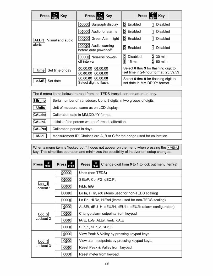
- 22
Press Key
Press
Key
Press
Key
00000 Bargraph display 0 Enabled 1 Disabled
00000 Audio for alarms 0 Enabled 1 Disabled
00000 Green Alarm light 0 Enabled 1 Disabled
00000 Audio warning before auto power-off
0 Enabled 1 Disabled
ALErt Visual and audio alerts
00000 Non-use power-off interval
0 Disabled 2 30 min
1 15 min 3 60 min
time Set time of day Select 0 thru 9 for flashing digit to set time in 24-hour format: 23.59.59
dAtE Set date
00.00.00 00.00.00
00.00.00 00.00.00
00.00.00 00.00.00 Select digit to flash.
Select 0 thru 9 for flashing digit to set date in MM.DD.YY format.
The 6 menu items below are read from the TEDS transducer and are read-only.
SEr_no. Serial number of transducer. Up to 8 digits in two groups of digits.
Units . Unit of measure, same as on LCD display.
CALdat. Calibration date in MM.DD.YY format.
CALInL. Initials of the person who performed calibration.
CALPer . Calibration period in days.
M-Id . Measurement ID. Choices are A, B or C for the bridge used for calibration.
When a menu item is “locked out,” it does not appear on the menu when pressing the > MENU key. This simplifies operation and minimizes the possibility of inadvertent setup changes.
Press
Press
Press Change digit from 0 to 1 to lock out menu item(s).
00000 Units (non-TEDS)
00000 SEtuP, ConFG, dEC.Pt
00000 FiLtr, triG
00000 Lo In, Hi In, rd0 (items used for non-TEDS scaling)
Loc_1 Lockout 1
00000 Lo Rd, Hi Rd, HiEnd (items used for non-TEDS scaling)
0000 ALSEt, dEU1H, dEU2H, dEU1b, dEU2b (alarm configuration)
0000 Change alarm setpoints from keypad
0000 tArE, LoG, ALErt, timE, dAtE
Loc_2 Lockout 2
0000 SEr_1, SEr_2, SEr_3
0000 View Peak & Valley by pressing keypad keys.
0000 View alarm setpoints by pressing keypad keys.
0000 Reset Peak & Valley from keypad.
Loc_3 Lockout 3
0000 Reset meter from keypad.
- 23
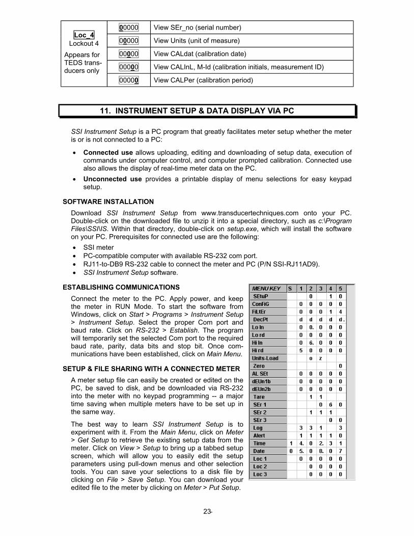
00000 View SEr_no (serial number)
00000 View Units (unit of measure)
00000 View CALdat (calibration date)
00000 View CALInL, M-Id (calibration initials, measurement ID)
Loc_4 Lockout 4
Appears for TEDS trans-ducers only
00000 View CALPer (calibration period)
11. INSTRUMENT SETUP & DATA DISPLAY VIA PC
SSI Instrument Setup is a PC program that greatly facilitates meter setup whether the meter is or is not connected to a PC:
• Connected use allows uploading, editing and downloading of setup data, execution of commands under computer control, and computer prompted calibration. Connected use also allows the display of real-time meter data on the PC.
• Unconnected use provides a printable display of menu selections for easy keypad setup.
SOFTWARE INSTALLATION
Download SSI Instrument Setup from www.transducertechniques.com onto your PC. Double-click on the downloaded file to unzip it into a special directory, such as c:\Program Files\SSI\IS. Within that directory, double-click on setup.exe, which will install the software on your PC. Prerequisites for connected use are the following:
• SSI meter • PC-compatible computer with available RS-232 com port. • RJ11-to-DB9 RS-232 cable to connect the meter and PC (P/N SSI-RJ11AD9). • SSI Instrument Setup software.
ESTABLISHING COMMUNICATIONS
Connect the meter to the PC. Apply power, and keep the meter in RUN Mode. To start the software from Windows, click on Start > Programs > Instrument Setup > Instrument Setup. Select the proper Com port and baud rate. Click on RS-232 > Establish. The program will temporarily set the selected Com port to the required baud rate, parity, data bits and stop bit. Once com-munications have been established, click on Main Menu.
SETUP & FILE SHARING WITH A CONNECTED METER
A meter setup file can easily be created or edited on the PC, be saved to disk, and be downloaded via RS-232 into the meter with no keypad programming -- a major time saving when multiple meters have to be set up in the same way.
The best way to learn SSI Instrument Setup is to experiment with it. From the Main Menu, click on Meter > Get Setup to retrieve the existing setup data from the meter. Click on View > Setup to bring up a tabbed setup screen, which will allow you to easily edit the setup parameters using pull-down menus and other selection tools. You can save your selections to a disk file by clicking on File > Save Setup. You can download your edited file to the meter by clicking on Meter > Put Setup.
- 24
With the meter connected, a Commands pull-down menu allows you to execute certain meter functions by using your computer mouse. You can reset individual meter functions, and display current, peak or valley readings.
MENU DISPLAY WITH A CONNECTED METER
After performing a Menu > Get Setup from the Main Menu, select View > Menu. Shown on the computer screen will be the sequential menu items and associated values to be displayed on the meter when stepping through the menu with the keypad.
• Click on any row on the computer screen to bring up a detailed help window for that menu item.
• Click on Print for a hardcopy, which you can then use for your records and as a convenient roadmap for programming the meter via its keypad.
MENU DISPLAY WITH NO METER CONNECTION
SSI Instrument Setup software is also an aid to meter programming when the meter is not connected to the PC. Upon launching the software, click on None. From File, click on Default Setup. Then click on View > Setup. Make all of the screen selections as if connected to a meter. When done, press on Main Menu, then on View > Menu. All of the selections made under Setup will now be shown on the computer screen, as illustrated on the previous page.
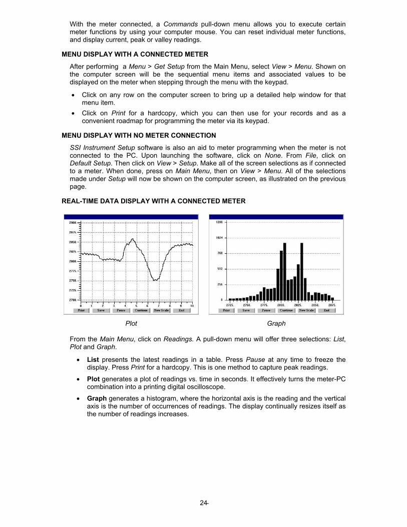
REAL-TIME DATA DISPLAY WITH A CONNECTED METER
Plot
Graph
From the Main Menu, click on Readings. A pull-down menu will offer three selections: List, Plot and Graph.
• List presents the latest readings in a table. Press Pause at any time to freeze the display. Press Print for a hardcopy. This is one method to capture peak readings.
• Plot generates a plot of readings vs. time in seconds. It effectively turns the meter-PC combination into a printing digital oscilloscope.
• Graph generates a histogram, where the horizontal axis is the reading and the vertical axis is the number of occurrences of readings. The display continually resizes itself as the number of readings increases.
- 25
12. CUSTOM CURVE LINEARIZATION
Curve.exe is a DOS-based, executable PC program used to set up the meter so that the readings have a user-defined, non-linear relationship with the input signal. The calculated linearizing parameters are downloaded into non-volatile memory of the meter. For example, it allows a meter to correct for transducer nonlinearity. The curve-fitting algorithm uses quadratic segments of varying length and curvature, and provides diagnostics to estimate curve fitting errors. The program is self-prompting, avoiding the need for a detailed printed manual. This manual section is only intended as an introduction and get-started guide.
PREREQUISITES
1) PC-compatible computer with an available Com 1 or Com 2 RS-232 port.
2) An RJ11-to-DB9 RS-232 cable to connect the meter and PC.
3) Curve.exe software (downloadable from website). GETTING STARTED
Download curve.exe into the same directory that will contain your data files, such as c:\curves. Set the meter baud rate to 9600. To do so, press the > MENU key to get to SEr 1, then set the entry to __050. Set the meter address to 1. To do so, press the > MENU key to get to SEr 2, then set the entry to _0011. To execute the program from Windows, simply double-click on curve.exe, which is an executable file. Follow the steps on computer screens, which will prompt you and provide extensive information. Pressing R (Enter) returns to the main menu. You will be given the choice to enter your data in one of four modes:
1) Text file entry mode, with an X value in one column and a Y value in another. There can be additional columns, which are ignored. The file must have a DOS name of up to 8 characters and the extension .RAW. There can be from 5 to 180 rows. X is the input value in mV. Y is the desired corresponding reading and can range from -99999 to 99999 with any decimal point.
2) 2-coordinate keyboard entry mode, where an actual X input signal is applied, and the desired Y reading is entered from the keyboard.
3) 2-coordinate file entry mode, where an actual X input signal is applied, and the desired Y reading is provided from a file.
4) Equation entry mode, where the coefficients of a polynomial Y = K1X^P1 + K2X^P2 + K3*X^P3 + … are entered. Up to 20 terms are allowed. An offset can be built into X.
You will be asked to supply the following:
LOW X-COORDINATE VALUE > (normally 0) LOW INPUT MEASUREMENT VALUE > (normally 0) HIGH X-COORDINATE VALUE > (normally 10,000 mV) HIGH INPUT MEASUREMENT VALUE > (normally 50,000)
Position the decimal point from 6=.XXXXX, 5=X.XXX, 4=XX.XXX, 3=XXX.XX, 2=XXXX.X, 1=XXXXX. Specify the same position that you specified in the dEc.Pt decimal point menu selection.
Follow the steps on the screens to finish generating the custom curve. When prompted to download the file to the meter, select Y. When prompted to set the meter to custom curve mode, also select Y.
KEYPAD CONTROL
You can take a meter in and out of custom curve linearization using the meter keypad. From the Menu mode, press the > MENU key to get to ConFG, then set the fifth digit to either 0 (normal linear operation) or to 1 (custom curve operation).
- 26
FILES USED OR CREATED BY CURVE.EXE
1) *.RAW is the raw input file either supplied or created by one of the four data entry methods.
2) *.DVD adds three columns from which the smoothness of the input data and obvious input errors can be judged. The more data points and the smoother the data, the better the curve fit.
3) *.NUM lists Y readings prior to custom curve linearization and addition of the decimal point.
4) *.CCF is an internal file used by the software.
5) *.SIM lists simulated linearized meter readings and calculated corresponding errors.
6) *.PRM contains the final hex data that is downloaded into the meter.
13. METER CALIBRATION
SSI meters are calibrated digitally at the factory prior to shipment using calibration equip-ment certified to NIST standards. Digital calibration eliminates much of circuitry that would be associated with analog calibration, providing superior long term accuracy and stability.
Calibration constants and the last meter calibration date are stored digitally in non-volatile memory in EEPROM. To retrieve the last calibration date, press RECALL for longer than 2 seconds to change to the Recall mode, then press UNITS.
Annual recalibration by the factory is recommended. Please contact Transducer Techniques for an RMA number.
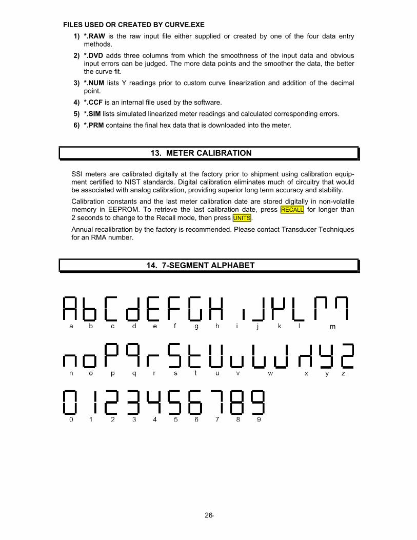
14. 7-SEGMENT ALPHABET
- 27
15. SPECIFICATIONS
Display
Type..........................................................Reflective LCD, 2.56” x 1.73” (65 x 44 mm) window Main numeric display.........................................6 seven-segment digits, 0.57” (14.5 mm) high Other displayed items......................................... 4-digit recall number, 10-segment bar graph, choice of 18 units of measure, battery life indicator, operating mode indicator Overload indication.............................................................Display flashes at 120% of HiRead
Response Rates
Normal data sampling rate ........... 15,360 samples/second (setting for 60 Hz noise rejection) 12,800 samples/second (setting for 50 Hz noise rejection) Normal conversion rate ...............................................................................Every 256 samples 60/second (setting for 60 Hz noise rejection) 50/second (setting for 50 Hz noise rejection) Fast conversion rates ...............................................Every 2 to 128 samples (programmable) Relay response rate .............................................................Same as Normal conversion rate Display update rate .................................................................................Every 16 conversions 3.750/second (setting for 60 Hz noise rejection) 3.125/second (setting for 50 Hz noise rejection) Peak & valley capture rate (selectable)............. Every 2, 4, 8, 16, 32, 64, 128 or 256 samples Peak & valley display update rate ..................3.750/second (setting for 60 Hz noise rejection) ........................................................................3.125/second (setting for 50 Hz noise rejection)
Analog-to-Digital Conversion
Recommended load ................................................................................ 120-1000 ohm bridge Bridge excitation voltage .................................................................................................... 3.0V Provision for variations in bridge excitation............................................. Ratiometric operation Signal span, max............................................................................................................. 15 mV Transducer sensitivity range .....................................................................................1-5 mV / V A-to-D converter resolution ...................................................................16 bits (65,536 counts) Signal resolution.................................................................................................... 0.5 µV/count Accuracy at 25°C........................................................................................................... ±1.5 µV Span Tempco ........................................................................................ 0.0015% of reading/°C Zero Tempco .............................................................................................................. 0.2 µV/°C NMR with no filtering ........................................................................................................ 90 dB Signal filtering (selectable) ...................................1) No filtering: 50 or 60 conversions/second
2) Batch average of 16 conversions 3) Moving average of conversions
Power Requirements
Internal battery....................................................................................Rechargeable lithium ion Battery capacity (nominal)................................................................................2400 mAh, 3.7V RUN time on single battery charge .................................. Up to 65 hours with 350 ohm bridge Battery charger ....................................................................................Wall plug AC power unit Batter charger input..................................................................... 100-240V ac, 50/60 Hz, 0.4A Batter charger output............................................................................................5.0V dc, 1.0A Battery charging time, max.............................................................................................8 hours Battery charge indication.................Battery symbol with 4 bars to show percent of full charge
4 bars = 80% - 100%, 3 bars = 60% - 80%, 2 bars = 40% - 60%, 1 bar = 20% - 40%, flashing battery symbol = 0% - 20%
Relay Output
Relay types........................................................... Dual relays with single common, solid state AC rating................................................. 120 mA @ 350Vac peak, 35 ohms series resistance DC rating ......................................................... 120 mA @ 350Vdc, 35 ohms series resistance Isolation to signal common.................................................................................. 5300 Vac rms Setpoint setup......................................................................................... Via keypad or RS-232 Response rate (selectable) ...... 60/second or 50/second (each 1 conversion or 256 samples) Response filtering (selectable) .................................................................. Filtered or unfiltered Active modes (selectable) ............Above or below setpoint, latching or non-latching, disabled Visual active Alarm Indication ...........................AL1 LED (yellow), AL2 LED (red), Go (green)
- 28
Audible active alarm indication..................................................................................Selectable Activation time delay (selectable)............................................................. 1 to 128 conversions Setpoint / lockout modes (selectable) ................................... 1) Display and change setpoints .....................................................................................2) Display but do not change setpoints ....................................................................................3) Neither display nor change setpoints
Serial Interface to PC
Signal levels .................................................................................................................. RS-232 Signal grounding .................................................................... Same ground as load cell signal Baud rates (selectable) ............................... 300, 600, 1200, 2400, 4800, 9600, 19200, 38400 Serial protocol................................................................... Point-to-point ASCII, PC compatible
Control Inputs Number of inputs .........................................................................................................2 (A & B) Input activation ..................................................................................................Short to ground Control input action .. Meter reset, function reset, display Peak or Valley, tare, tare reset, Log
Mechanical
Dimensions................................................................ 1.28” x 3.30” x 7.50” (32 x 84 x 185 mm) Weight .................................................................................................................. 10 oz (280 g) Case material ................................................................................................ABS-94HB plastic Provision for stand............................ 3 stainless steel inserters, 8-32 UNC threads, 3/8” deep ............................................ 1.500” triangle base, 1.750 triangle height (see photo on page 6) Keypad ............................................................... Membrane type, 8-keys with tactile feedback Display type ....................................................................................................... Reflective LCD Displayed info .........6 large digits, 4 small digits, two bar graphs, units of measure, indicators Electrical connectors .......................... DB9 male for TEDS and signal connection to load cell, 3-pin jack plus detachable connector for dual relay output, 6-pin RJ11 jack for RS-232 link to computer, Coaxial connector for external power unit
Environmental
Operating temperature ........................................................................................... 0°C to 55°C Storage temperature ........................................................................................... -20°C to 60°C Relative humidity ........................................................ 95% from 0°C to 40°C, non-condensing Environmental sealing ....................................................................Dust and humidity resistant
Peak-to-Peak Noise as a Percentage of Full Scale
Load cell sensitivity Conversion type
Filter setting
Filter time constant 1 mV/V 2 mV/V 3 mV/V 4 mV/V
Normal A No filter 0.03 0.02 0.01 < 0.01
Normal 1 16 conv. batch avg. < 0.01 < 0.01 < 0.01 < 0.01
Normal 2 0.08 sec 0.01 0.01 < 0.01 < 0.01
Normal 3 0.14 sec 0.01 < 0.01 < 0.01 < 0.01
Normal 4 0.3 sec < 0.01 < 0.01 < 0.01 < 0.01
Normal 5 0.6 sec < 0.01 < 0.01 < 0.01 < 0.01
Normal 6 1.2 sec < 0.01 < 0.01 < 0.01 < 0.01
Normal 7 2.4 sec < 0.01 < 0.01 < 0.01 < 0.01
Normal 8 4.8 sec < 0.01 < 0.01 < 0.01 < 0.01
Normal 9 9.6 sec < 0.01 < 0.01 < 0.01 < 0.01
Fast 1 No filter 120 conv./sec 0.06 0.03 0.02 0.01
Fast 2 No filter 240 conv./sec 0.08 0.04 0.03 0.02
Fast 3 No filter 480 conv./sec 0.11 0.06 0.04 0.03
Fast 4 No filter 960 conv./sec 0.16 0.08 0.05 0.04
Fast 5 No filter 1920 conv./sec 0.23 0.11 0.08 0.06
Fast 6 No filter 3840 conv./sec 0.32 0.16 0.11 0.08
Fast 7 No filter 7680 conv./sec 0.45 0.22 0.15 0.11
- 29
16. GLOSSARY OF TERMS
Adaptive Filter Threshold A threshold which causes an adaptive moving average filter to be reset to the
latest reading when the accumulated difference between individual readings and the filtered reading exceeds that threshold. Adaptive moving average filtering allows a meter to respond rapidly to actual changes in signal while filtering out normal noise.
Alarm, Latched An alarm that stays actuated until reset. Latched alarms can maintain a shut-
down condition or maintain an alarm until acknowledged by an operator.
Alarm, Non-latched An alarm which changes state automatically when the reading rises above a
specified limit and changes back automatically when the reading falls below a limit. Also called “Auto Reset.”
Auto-filter A selectable digital filter mode that automatically selects an appropriate moving average filter time constant for the encountered noise condition.
Batch Average Filter A digital filter mode where readings are the displayed average of 16 conver-
sions. Conversions are made at 60/second in a 60 Hz environment and 50/second in a 50 Hz environment.
Deviation Band A value which controls relay action symmetrically around a setpoint. The relay
activates when the reading falls within the deviation band, and de-activates when the reading falls outside. A deviation value (e.g., 50 counts) is set up around both sides of the setpoint to create a deviation band or passband (e.g., 100 counts), which equals two deviation values.
First Peak The first maximum (or most positive) reading followed by a decrease of a selectable percentage Full Scale since that maximum was last reset.
Full Scale The reading range equal to Hi Rd - Lo Rd.
Hysteresis A value which controls relay action symmetrically around a setpoint. The relay closes (or opens) when the reading goes above the setpoint plus the hysteresis value, and opens (or closes) when the reading falls below the setpoint less the hysteresis value. A narrow hysteresis band is often used to minimize relay chatter around a setpoint due to electrical noise or signal feedback caused by load switching. A wide hysteresis band can be used for control applications. The hysteresis band equals two hysteresis values.
Moving Average Filter A digital filter mode that displays a weighting moving average of readings.
Readings are taken at 60/second in a 60 Hz power environment and 50/second in a 50 Hz power environment. Display update rates remain at 3.75/second at 60 Hz and 3.13/second at 50 Hz. There are eight moving average modes:
Old average x 1/2 + new reading x 1/2 (equivalent to 0.08 sec RC time constant). Old average x 3/4 + new reading x 1/4 (equivalent to 0.15 sec RC time constant). Old average x 7/8 + new reading x 1/8 (equivalent to 0.3 sec RC time constant). Old average x 15/16 + new reading x 1/16 (equivalent to 0.6 sec RC time constant). Old average x 31/32 + new reading x 1/32 (equivalent to 1.2 sec RC time constant). Old average x 63/64 + new reading x 1/64 (equivalent to 2.4 sec RC time constant). Old avg. x 127/128 + new reading x 1/128 (equivalent to 4.8 sec RC time constant). Old avg. x 255/256 + new reading x 1/256 (equivalent to 9.6 sec RC time constant).
Peak Display The maximum (or most positive) reading since that maximum was last reset. Reset can be via the meter keypad, a control input, or an RS-232 command. For Normal conversions, the displayed value can be the peak of filtered or unfil-tered readings.

- 30
Plug & Play A system where a TEDS sensor and an instrument are automatically scaled as a system at power on.
Reading The current value displayed by the meter. Readings are updated at 3.75/second in a 60 Hz environment and 3.125/second in a 50 Hz environment.
Reset There are three types of Reset:
Peak and Valley Reset. Achieved by simultaneously pressing the RESET and PEAK keys.
Latched Alarm Reset. Achieved by simultaneously pressing the RESET and ALARMS keys.
Meter Reset. Causes the meter to reinitialize and take a tare reading when set up for auto-tare. Achieved by powering up the meter, pressing the RESET and MENU keys simultaneously, stepping through all menu items, grounding an external control input, or supplying an ASCII command. rESEt is displayed briefly.
RUN Mode The normal operating mode of the meter, where readings are taken, as opposed to the Menu or Recall modes.
Sampling Rate The rate at which data is collected for further processing. In the SSI, this is
15,360 samples/second.
Scaling The setup process which relates signal inputs to numeric readings in engineer-ing units (such as psi).
Scaling, Coordinates of 2 Points Method A scaling method where four numbers are entered manually: low input, desired
reading at low input; high input, and desired reading at high input. The meter then applies a straight line fit.
Scaling, Reading Coordinates of 2 Points Method A scaling method that uses actual measurements of low and high inputs. A
known low signal is first applied to the meter, and the desired low reading is entered. A known high signal is then applied, and the desired high reading is entered. The meter then applies a straight line fit. This scaling method has the advantage of calibrating the transducer and meter as a system. The actual voltage or current at either point does not need to be known.
Setpoint A value compared to the reading to force the state of a relay. Term often used interchangeably with “alarm setpoint.” The relay action can be latching or non-latching and utilize a hysteresis band or deviation band. Hysteresis bands and deviation bands are specified by two symmetrical limits around the setpoint.
Tare A constant value that is subtracted from the meter reading to set the reading to zero. In weighing applications, tare refers to the weight of the empty container. Tare is subtracted from gross weight to obtain net weight.
TEDS 1451.4 Transducer Electronic Data Sheet (TEDS), a set of electronic data in a format defined by the IEEE 1451.4 standard. This data is on a chip that is part of the transducer. The data specifies the type of sensor, the scaling constants, and the unit of measure. By incorporating this chip, the sensor can describe itself to a smart load cell meter or network Plug and Play system configuration.
Valley Display The minimum (or most negative) reading since that minimum was last reset.
Reset can be via the meter keypad, a control input, or an RS-232 command. The displayed value can reflect the filtered or unfiltered reading.
Zero A setting by ZEro menu item, which allows the meter to display zero when the signal level is below a specified percentage of full scale span. This avoids meaningless noise readings when the reading should be zero.

- 31
17. WARRANTY & REPAIR POLICY
Limited Warranty on Products
Any of our products which, under normal operating conditions, proves defective in material or in workmanship within one (1) year from the date of shipment by Transducer Techniques, will be repaired or replaced free of charge provided that you obtain a return material authorization from Transducer Techniques and send the defective product, transportation charges prepaid with notice of the defect, and establish that the product has been properly installed, main-tained, and operated within the limits of rated and normal usage. Replacement product will be shipped F.O.B. our plant. The terms of this warranty do not extend to any product or part thereof which, under normal usage, has an inherently shorter useful life than one year. The replacement warranty detailed here is the Buyer’s exclusive remedy, and will satisfy all obligations of Transducer Techniques, whether based on contract, negligence, or otherwise. Transducer Techniques is not responsible for any incidental or consequential loss or damage which might result from a failure of any Transducer Techniques’ product. This express warranty is made in lieu of any and all other warranties, expressed or implied, including implied warranty of merchantability or fitness for particular purpose. Any unauthorized disassembly or attempt to repair voids this warranty.
Obtaining Service Under Warranty
Advance authorization is required prior to the return to Transducer Techniques. Before return-ing the item(s), either write to the Repair Department c/o Transducer Techniques, 42480 Rio Nedo, Temecula, CA 92590, or call (951) 719-3965 with: 1) a part number; 2) a serial number for the defective product; 3) a technical description of the defect; 4) a no-charge purchase order number (so products can be returned to you correctly); and, 5) ship to and bill to addresses. Shipment to Transducer Techniques shall be at Buyer’s expense, and repaired or replacement items will be shipped F.O.B. our plant in Temecula CA. Non-verified problems or defects may be subject to a $75 evaluation charge. Please return the original calibration data with the unit.
Obtaining Non-Warranty Service
Advance authorization is required prior to the return to Transducer Techniques. Before return-ing the item(s), either write to the Repair Department c/o Transducer Techniques, 42480 Rio Nedo, Temecula, CA 92590, or call (951) 719-3965 with: 1) a model number; 2) a serial number for the defective product; 3) a technical description of the malfunction; 4) a purchase order number to cover Transducer Techniques’ repair cost; and 5) ship to and bill to addresses. After the product is evaluated by Transducer Techniques, we will contact you to provide the estimated repair costs before proceeding. The minimum evaluation charge is $75. Shipment to Transducer Techniques shall be at Buyer’s expense, and repaired items will be shipped to you F.O.B. our plant in Temecula, CA. Please return the original calibration data with the unit.
Repair Warranty
All repairs of Transducer Techniques’ products are warranted for a period of 90 days from the date of shipment. This warranty applies only to those items that were found defective and repaired; it does not apply to products in which no defect was found and returned as is, or merely recalibrated. Out-of-warranty products may not be capable of being returned to the exact original specifications or dimensions.
FOR TECHNICAL SUPPORT, CALL
(800) 344-3965 / FAX (951) 719-3900
Printed in U.S.A.

- 32
Transducer Techniques®
PRECISION MEASUREMENT SYSTEMS
42480 RIO NEDO, TEMECULA, CA 92590 (951) 719-3965 FAX (951) 719-3900 URL: www.transducertechniques.com
Email: [email protected]

- 33
32,1,2,31,30,3,4,29,28,5,6,27,26,7,8,25,24,9,10,23,22,11,12,21,20,13,14,19,18,15,16,17