SS7 User’s Guide · SS7 Support for WebSphere Voice Response SS7 User’s Guide Version 4.2...
173
SS7 Support for WebSphere Voice Response SS7 User’s Guide Version 4.2 GC34-6613-03
Transcript of SS7 User’s Guide · SS7 Support for WebSphere Voice Response SS7 User’s Guide Version 4.2...

SS7 Support for WebSphere Voice Response
SS7 User’s Guide
Version 4.2
GC34-6613-03
���

Note
Before using this information and the product it supports, read the general information under “Notices” on
page 119.
Fourth edition (August 2008)
This edition applies to Version 4, Release 2 of IBM® SS7 Support for WebSphere®Voice Response (program numbers
5799-GZL, 5799-GZQ), and to all subsequent releases and modifications until otherwise indicated in new editions.
Make sure you are using the correct edition for the level of the product.
© Copyright International Business Machines Corporation 2001, 2008. All rights reserved.
US Government Users Restricted Rights – Use, duplication or disclosure restricted by GSA ADP Schedule Contract
with IBM Corp.
©Copyright SS8 Networks Inc. 1997, 2004.

Contents
Figures . . . . . . . . . . . . . vii
Tables . . . . . . . . . . . . . . ix
About this book . . . . . . . . . . xi
Who should use this book . . . . . . . xi
Typographic conventions . . . . . . . . xi
Accessibility . . . . . . . . . . . . xii
Notes on terminology . . . . . . . . . xii
Where to find more information . . . . . xiii
Useful Web sites . . . . . . . . . xiii
Making comments on this book . . . . . xiii
Chapter 1. Introducing SS7 Support for
WebSphere Voice Response . . . . . . 1
What is SS7? . . . . . . . . . . . . 1
SS7 links and network components . . . . . 1
The SS7 protocol stack . . . . . . . . . 1
Using SS7 with IBM WebSphere Voice
Response . . . . . . . . . . . . . 5
Example configurations . . . . . . . . 6
A minimum configuration using one pSeries
computer . . . . . . . . . . . . 7
A configuration using one SS7 Server and
two SS7 Clients . . . . . . . . . . 7
A configuration using two SS7 Servers and
two SS7 Clients with some redundancy . . 9
A maximum configuration with full
redundancy . . . . . . . . . . . 10
Chapter 2. Planning . . . . . . . . . 13
Software . . . . . . . . . . . . . 13
Hardware . . . . . . . . . . . . . 13
SS7 adapter (mandatory) . . . . . . . 13
Supported pSeries computers . . . . . 13
Configuration considerations . . . . . . 14
Licensing the Distributed7 package . . . . 14
Call capacity . . . . . . . . . . . . 15
Preparing for installation . . . . . . . . 15
Collecting System Parameters . . . . . . 16
SS7 interconnection information . . . . 16
Physical Connections . . . . . . . . 17
Grouping Connection and Addressing SS7 18
Additional Routing . . . . . . . . 18
Connecting the Voice Bearers . . . . . 18
Chapter 3. Installing SS7 Support for
WebSphere Voice Response . . . . . . 21
Pre-installation checking . . . . . . . . 21
Locating the required files . . . . . . . 21
Installation on an SSI server . . . . . . . 22
Pre-installation . . . . . . . . . . 22
Installing the D7 Enablement package . . 22
Configuring the SS7 Cluster . . . . . . 23
Configuring the AIX machine for SSI
Server usage . . . . . . . . . . . 23
Installation and configuration complete . . 23
Installation of SS7 Adapters . . . . . . . 23
Installation on an SS7 Server . . . . . . 23
Pre-installation . . . . . . . . . . 24
Installing the D7 and the D7 Enablement
packages . . . . . . . . . . . . 24
Configuring the SS7 cluster . . . . . . 24
Configuring the AIX machine for SS7
Server Usage . . . . . . . . . . . 25
Installation and configuration complete . . 28
Installation on a WebSphere Voice Response
client . . . . . . . . . . . . . . 28
Pre-installation . . . . . . . . . . 28
Installing the D7 and the D7 Enablement
packages . . . . . . . . . . . . 28
Configuring the SS7 cluster . . . . . . 29
Configuring the AIX machine for
WebSphere Voice Response client usage . . 29
Installation and configuration complete . . 32
Installation of a combined SS7 Server and
WebSphere Voice Response client . . . . . 32
Pre-installation . . . . . . . . . . 32
Installing the D7 and the D7 Enablement
packages . . . . . . . . . . . . 32
Configuring for combined WebSphere
Voice Response client and SS7 Cluster . . 33
Configuring the AIX machine for
WebSphere Voice Response client and SS7
Server usage . . . . . . . . . . . 34
Installation and configuration Complete . . 39
Putting into production . . . . . . . . 39
Custom servers . . . . . . . . . . 39
D7 package . . . . . . . . . . . 39
© Copyright IBM Corp. 2001, 2008 iii

D7 Alarm Logging . . . . . . . . . 40
Chapter 4. Configuration using SS7itty . . 43
Preparation . . . . . . . . . . . . 43
Running SS7itty . . . . . . . . . . . 43
Configure Environmental Conditions . . . 44
Configure AIX Systems . . . . . . . 45
Configure SS7 Server . . . . . . . . . 46
Configure WebSphere Voice Response client 46
Configure SS7 Links . . . . . . . . . 47
Configure SS7 Link sets . . . . . . . . 48
Configure SS7 Route Sets . . . . . . . 49
Configure SS7 trunks to WebSphere Voice
Response trunks . . . . . . . . . . 50
Generate SS7 Configuration Files . . . . . 51
Importing or exporting an SS7 configuration 52
Pack Configuration . . . . . . . . . . 52
Chapter 5. Managing and Monitoring SS7
Support for WebSphere Voice Response . 55
SS7_MAINT – the general maintenance utility 55
Enablement Operation . . . . . . . 56
D7 Operation . . . . . . . . . . 56
MML Configuration Loader . . . . . . 57
HouseKeeping . . . . . . . . . . 57
D7 Maintenance programs . . . . . . 58
SS7 Server/WebSphere Voice Response
client . . . . . . . . . . . . . 58
iFix Loading . . . . . . . . . . . 59
Fault Finding . . . . . . . . . . 59
D7 software release . . . . . . . . 59
ss7view – D7 Enablement monitoring tool . . 60
ss7view – help options . . . . . . . 60
ss7view – monitor circuits . . . . . . 60
ss7view –event . . . . . . . . . . 62
ss7view –message . . . . . . . . . 62
ss7view –trigger . . . . . . . . . . 63
ss7view -trace . . . . . . . . . . 64
ss7view –stat . . . . . . . . . . . 64
ss7view –info . . . . . . . . . . 65
ss7view –cause <name/value> . . . . . 66
SS8 commands . . . . . . . . . . . 66
AccessMonitor . . . . . . . . . . 66
AccessStatus . . . . . . . . . . . 67
ebs_showlink . . . . . . . . . . 67
D7WVRErrorReport . . . . . . . . . 68
Startup parameters . . . . . . . . . 68
Collecting event and trace information . . . 69
Event information . . . . . . . . . 69
Trace information . . . . . . . . . 69
Chapter 6. Information elements passed to
WebSphere Voice Response . . . . . . 71
Tag presentation and omissions . . . . . 71
Country and network variants . . . . . . 72
Tags types and descriptions . . . . . . . 72
User-to-user information [USR2USR] . . . 72
Called Number [CLDN] . . . . . . . 72
Calling Number [CLGP] . . . . . . . 73
Original Number [ORIGIN] . . . . . . 73
Redirecting Number [REDIRN] . . . . 73
Redirecting Information [REDINFO] . . . 74
User Teleservices Information [UTI] (ITU
Only) . . . . . . . . . . . . . 75
User Services Information [USI] . . . . 75
Generic Address [GENERICADDR] . . . 75
Service Activation Parameter
[SERVICEACTIVATION] . . . . . . . 76
Jurisdiction Information Parameter [JINFO] 76
Party Information Parameter [PINFO] . . 77
Release Cause Codes [CAUSE] . . . . . 77
Protocol Type [PROTOCOL] . . . . . 78
Switching SS7 Default values [ISUPPARM] 78
Special case tags . . . . . . . . . . 79
Release with new Called Party
Number[NEWCLDN] . . . . . . . . 79
System variables . . . . . . . . . . 79
Chapter 7. Problem determination . . . . 81
Stage 1: Is the SS7 Server working? . . . . 81
Stage 1a: Machine is not a Server . . . . 82
Stage 1b: D7 package is not running . . . 82
Stage 1c: D7 system configured for SS7
Server . . . . . . . . . . . . . 82
Stage 1d: MTP-3(upmd) / ISUP(isupd) is
not running . . . . . . . . . . . 82
Stage 2: Which other machines are present? 82
Stage 2a : A machine is missing from the
cluster . . . . . . . . . . . . . 83
Stage 2b: The named machine in
RMTHOST has been part of the SS7 cluster
but has since failed . . . . . . . . 83
Stage 2c: A machine containing an SS7
adapter card is present in the SS7 cluster,
but is not activated . . . . . . . . . 83
Stage 2d: The machines within the SS7
cluster appear to be in order . . . . . 83
Stage 3: Is D7 working on a WebSphere Voice
Response Client? . . . . . . . . . . 84
Stage 3a: The machine is not a WebSphere
Voice Response client . . . . . . . . 84
iv SS7 User’s Guide

Stage 3b: The machine is correctly running
as a WebSphere Voice Response client. . . 85
Stage 3c: D7 package is not running . . . 85
Stage 4: Machine has been present in the SS7
cluster but is not now? . . . . . . . . 85
Stage 4a: The machine has been configured
for SS7 Server . . . . . . . . . . 86
Stage 4b: The machine has been configured
as a WebSphere Voice Response client . . 86
Stage 4c: D7 package is not running . . . 86
Stage 4d: There is a problem starting this
machine as an SS7 Server . . . . . . 86
Stage 5: Two machines are not
communicating . . . . . . . . . . . 86
Stage 5a: There is no communication
between the machines. . . . . . . . 87
Stage 5b: There has been a connection
between the machines at one time. . . . 87
Stage 5c: There is a good connection
between the two machines . . . . . . 87
Stage 5d: There is a configuration problem
in defining the machines within the SS7
Cluster . . . . . . . . . . . . . 87
Stage 6: SS7 Adapter checks . . . . . . . 87
Stage 6a: Locate a missing adapter . . . 88
Stage 7: SS7 Links. . . . . . . . . . . 89
Stage 8a: The physical connection for this
Link is faulty . . . . . . . . . . . 90
Stage 8b: Incorrect Point Code value . . . 90
Stage 9: Is the Enablement package working? 90
Stage 9a: The custom servers have not
been imported. . . . . . . . . . . 91
Stage 9b: A custom server is not running 91
Stage 9c: One or more configuration files
cannot be located . . . . . . . . . 91
Stage 9d . . . . . . . . . . . . 91
Stage 9e . . . . . . . . . . . . 92
Stage 10 . . . . . . . . . . . . . 92
Stage 10a: Possible message
synchronization problem . . . . . . . 93
Stage 11: Inbound Traffic . . . . . . . . 94
Stage 11a: Verify that the call is coming
into a WebSphere Voice Response client . . 94
Stage 11b: An inbound call is not being
received by the SS7 cluster . . . . . . 95
Stage 11c: SS7_D7 has rejected the call
request, possibility with invalid
parameters. . . . . . . . . . . . 95
Stage 11d: Possible problem in the
call-answering mechanism of WebSphere
Voice Response . . . . . . . . . . 95
Stage 11e: The inbound call is connected
and the application is running. . . . . . 95
Stage 12: Testing outbound calls . . . . . 96
Stage 12a: Check the returned value from
the application’s Makecall instruction . . 96
Stage 12b: The network is rejecting the call 96
Redundancy – WebSphere Voice Response
client failure. . . . . . . . . . . . . 97
The effects of call overload . . . . . . . 97
Obscure Problems . . . . . . . . . . 97
HMCG Alarm Message . . . . . . . 97
LAN Configuration problems . . . . . 98
Unexpected primitive . . . . . . . . 98
Machine locks up in dual LAN
configuration . . . . . . . . . . . 98
Chapter 8. Migration . . . . . . . . . 99
SS7 Server migration . . . . . . . . . 99
WebSphere Voice Response client migration 99
Adding additional machines to the SS7
Cluster . . . . . . . . . . . . . . 99
Updating existing machines . . . . . . 100
Changes or Removals from SS7 Cluster . . 100
Appendix A. Sample forms for recording
information . . . . . . . . . . . 101
Appendix B. Uninstalling SS7 Support for
WebSphere Voice Response . . . . . 105
Appendix C. Configuration files . . . . 107
Master configuration file . . . . . . . 107
Trunk association file . . . . . . . . 107
Logging and event file . . . . . . . . 109
Trace logging . . . . . . . . . . 109
Error options . . . . . . . . . . 109
Event options . . . . . . . . . . 110
AlertSupress=[*(<AlertNumber>,|
<Alertnumber>-<Alertnumber>,)] . . . 111
Statistical Information . . . . . . . 111
Service configurable options . . . . . . 111
Outbound Channel Assignment . . . . 111
Parameter compatibility checking . . . 112
Tag handling . . . . . . . . . . 113
StayAlive . . . . . . . . . . . 114
Miscellaneous . . . . . . . . . . 114
Distributed7 parameters . . . . . . . 114
Contents v

SV187 Call User 1 / SV188 Call User 2
assignments . . . . . . . . . . . 114
ISUP default IE parameters . . . . . . 114
Creating a Clone . . . . . . . . . 115
AlarmTranslation.cfg . . . . . . . . . 115
User file . . . . . . . . . . . . . 116
Appendix D. Typical ISUP message flows 117
Notices . . . . . . . . . . . . . 119
Trademarks . . . . . . . . . . . . 121
Glossary . . . . . . . . . . . . 123
List of WebSphere Voice Response and
associated documentation . . . . . . 149
WebSphere Voice Response software . . . 149
IBM hardware for use with WebSphere Voice
Response . . . . . . . . . . . . 150
Withdrawn from marketing but still
supported . . . . . . . . . . . 150
WebSphere Voice Response related products 150
WebSphere Voice Server for
Multiplatforms . . . . . . . . . . 150
Unified Messaging for WebSphere Voice
Response . . . . . . . . . . . 151
AIX and the IBM pSeries computer . . . 151
HACMP . . . . . . . . . . . . 151
SS7 . . . . . . . . . . . . . 151
Integrated Services Digital Network . . . 152
Bellcore Specifications for ADSI Telephones 153
Index . . . . . . . . . . . . . 155
vi SS7 User’s Guide

Figures
1. SS7 protocol stack . . . . . . . . 2
2. Typical layout for SS7 Support for
WebSphere Voice Response signaling
components (minimum configuration) . . 7
3. Configuration using one SS7 Server and
two SS7 Clients . . . . . . . . . 8
4. Configuration using two SS7 Servers and
two SS7 Clients . . . . . . . . . 9
5. Maximum configuration with full
redundancy . . . . . . . . . . 11
6. The Properties panel for the
D7WVRErrorReport custom server . . 41
7. The AccessMonitor screen . . . . . 66
8. The AccessStatus screen . . . . . . 67
9. The link monitoring program screen 89
© Copyright IBM Corp. 2001, 2008 vii

viii SS7 User’s Guide

Tables
© Copyright IBM Corp. 2001, 2008 ix

x SS7 User’s Guide

About this book
This book provides an overview of how you can use the IBM® SS7 Support
for WebSphere® Voice Response product with IBM WebSphere Voice Response
for AIX® to connect to telephone switches using the SS7 protocol. This book
aims to help you install and configure the product, and provide system
administration support for the product once it is running.
This book describes SS7 Support for WebSphere Voice Response Version 4.2. If
you are a newcomer to using the SS7 protocol with WebSphere Voice
Response, start with Chapter 1, “Introducing SS7 Support for WebSphere Voice
Response,” on page 1, which provides an overview and describes some
typical installations.
Who should use this book
This book is for the person who installs and configures SS7 Support for
WebSphere Voice Response in your business. It assumes some knowledge of
telephony (in particular SS7), WebSphere Voice Response for AIX, the AIX
operating system, and pSeries™ computer hardware.
Typographic conventions
This book uses the following typographic conventions:
boldface
Identifies an item that is in a WebSphere Voice Response window. The
item might be a keyword, an action, a field label, or a pushbutton.
Whenever one of the steps in a procedure includes a word in
boldface, look in the window for an item that is labeled with that
word.
boldface italics
Are used for emphasis. Take extra care wherever you see bold italics.
italics Identify one of the following:
v New terms that describe WebSphere Voice Response components or
concepts. A term that is printed in italics is usually followed by its
definition.
v Parameters for which you supply the actual names or values.
v References to other books.
monospace
Identifies one of the following:
© Copyright IBM Corp. 2001, 2008 xi

v Text that you type in an AIX window. Because AIX is case sensitive,
ensure that you type the uppercase and lowercase characters exactly
as shown.
v Names of files and directories (path names).
Accessibility
WebSphere Voice Response for AIX is a voice application enabler. The
applications that are developed to run on WebSphere Voice Response provide
telephone access to business data and services. In this way, WebSphere Voice
Response provides accessibility for people who cannot access the data and
services by using regular Web pages or traditional graphic interfaces. These
telephone user interfaces are fully accessible to people who are blind or have
low vision and, if speech recognition is used, to people with mobility
impairments or limited hand use. Speech recognition capability can be
provided by products such as IBM WebSphere Voice Server. In addition,
support for users of Telephony Devices for the Deaf (TDD) is provided as part
of the WebSphere Voice Response product.
With WebSphere Voice Response you can perform many application
development and system administration tasks with a text editor or line
commands—these are accessible if you use a screen reader product to
interface with them. Also, the default settings of the WebSphere Voice
Response graphical user interface can be changed to produce large fonts and
high contrast colors. Details of how to use these accessibility features can be
found in the WebSphere Voice Response for AIX: User Interface Guide.
Alternatively, application development can be done with Java™ or VoiceXML
development tools that are supplied by IBM and third parties.
You can also use a screen-reader product to access the WebSphere Voice
Response publications in HTML format (for details of their availability refer to
“List of WebSphere Voice Response and associated documentation” on page
149 at the back of this book).
Notes on terminology
v A glossary of commonly-used terms is at the end of this book.
v The full product name of WebSphere Voice Response for AIX with DirectTalk®
Technology is generally abbreviated in this book to WebSphere Voice Response.
v The term pSeries™ is generically used in this book to refer both to PCI-based
RS/6000® computers and to appropriate models of the System p5™ and
pSeries ranges. (Consult your IBM representative for details of models that
are supported for use with WebSphere Voice Response.) RS/6000 computers
with an MCA bus are not supported.
About this book
xii SS7 User’s Guide

v The IBM Quad Digital Trunk Telephony PCI Adapter is generally referred to in
this book by its abbreviation DTTA. This adapter is a replacement for the
IBM ARTIC960RxD Quad Digital Trunk PCI Adapter, which is generally
referred to by the abbreviation DTXA.
v References made to the VoiceXML 2.1 specification are intended to include
VoiceXML 2.0 unless otherwise specified.
In this book, IBM SS7 Support for WebSphere Voice Response is generally
referred to as SS7 Support for WebSphere Voice Response, and Distributed7 is
abbreviated to D7.
Where to find more information
The information provided in the WebSphere Voice Response library will help
you complete WebSphere Voice Response tasks more quickly. A complete list
of the available books and where you can obtain them is shown in “List of
WebSphere Voice Response and associated documentation” on page 149.
Useful Web sites
The following Web sites are useful sources of information about WebSphere
Voice Response and related products:
IBM WebSphere voice products
Select the Products link on the Pervasive Computing Software home
page at http://www.ibm.com/software/pervasive
IBM WebSphere developerWorks resources (including WebSphere Voice
products)
http://www.ibm.com/developerworks/websphere
VoiceXML Version 2.0 and 2.1 specifications
http://www.voicexml.org/spec.html
CCXML Version 1.0 specification
http://www.w3.org/TR/ccxml
CallPath
For more information on CallPath products go to the Genesys Web
site at http://www.genesyslab.com
Making comments on this book
If you especially like or dislike anything about this book, feel free to send us
your comments.
You can comment on what you regard as specific errors or omissions, and on
the accuracy, organization, subject matter, or completeness of this book. Please
limit your comments to the information that is in this book and to the way in
accessibility
About this book xiii

which the information is presented. Speak to your IBM representative if you
have suggestions about the product itself.
When you send us comments, you grant to IBM a nonexclusive right to use or
distribute the information in any way it believes appropriate without
incurring any obligation to you.
You can get your comments to us quickly by sending an e-mail to
[email protected]. Alternatively, you can mail your comments to:
User Technologies
IBM United Kingdom Laboratories,
Mail Point 095, Hursley Park,
Winchester, Hampshire, SO21 2JN, United Kingdom
Please ensure that you include the book title, order number, and edition date.
making comments on this book
xiv SS7 User’s Guide

Chapter 1. Introducing SS7 Support for WebSphere Voice
Response
This chapter introduces Signaling System 7 (SS7), and how SS7 works with
WebSphere Voice Response for AIX. This chapter also includes four examples
of how you might configure WebSphere Voice Response when using SS7, from
the simplest to the maximum supported configuration.
What is SS7?
SS7 is the ubiquitous communications protocol that is used within and
between telephony networks of the world for system management, call setup
and tear-down, and other network functions. Although there are slight
variations in the fine detail of SS7 implementations used around the world, all
telephone companies use the same set of protocols known generically as SS7.
Because the signaling is on a separate network to voice traffic, SS7 allows the
use of features such as automatic callback when a called number is busy.
Messages about the states of the voice lines are sent and received on the
signaling network so voice lines are not tied up until both parties are known
to be available to speak.
SS7 is used for many other functions within a telephone network. Essentially,
when the computer in one telephone exchange or switch needs to talk to
computers elsewhere in the network (either to other switches or to standalone
machines such as those used for billing and advanced services), SS7 messages
are always used.
SS7 links and network components
SS7 uses discrete messages to exchange information, the messages being
passed between switches and other end points using packet switched data
links. There are two types of connections in a telephony network:
v Packet-switched links used for SS7 messages (but not voice data).
v Circuit-switched links used for voice data (but not SS7 messages).
The SS7 protocol stack
SS7 is structured in a multi-layered stack which corresponds closely to the
layers of the standard OSI model, although some SS7 components span a
number of layers, as shown in Figure 1 on page 2.
© Copyright IBM Corp. 2001, 2008 1

The SS7 component parts are:
Layer 1 (Physical): MTP-1 (Message Transfer Part-1)
MTP-1 defines the physical means by which SS7 messages are
transferred from one node to another. For E1 ot T1 networks, the
physical layer is usually a timeslot of an E1 or T1 frame respectively.
The physical layer specifies only how a sequence of bits is conveyed
from one SS7 node to another. It says nothing about the actual
meaning of the bits or how they are grouped together to form a
message.
Layer 2 (Data Link): MTP-2
MTP–2 defines how an MTP-1 bit transfer mechanism is used to
reliably pass variable length messages from one SS7 node to another.
MTP-2 uses a variant of the High level Data Link Control (HDLC)
used in most modern data transfer protocols. This uses a delimiter to
define the start and end of a data frame, prevents flags occurring in a
frame (bit-stuffing) and protection for the entire frame (CRC at the
end). It also defines how CRC errors are handled (by error response
and retransmission).
MTP-2 says nothing about the actual content of a message. It simply
defines a mechanism by which a message of any length can be sent
100% reliably between SS7 nodes and can be used by higher layers of
the SS7 protocol.
Application
Presentation
Session
Transport
Network
Data Link
Physical
7
6
5
4
3
2
1
OSI Model SS7 Stack
MTP Layer 1
MTP Layer 2
MTP Layer 3
IBM WebSphere Voice Response for AIX
TUP ISUP TCAP
MAP INAP OMAP
SCCP
Signaling Process Custom Server
Figure 1. SS7 protocol stack
SS7 links and network components
2 SS7 User’s Guide

MTP-2 knows nothing beyond the single point-to-point link it
operates on.
Layer 3 (Network Layer): MTP–3
MTP-3 builds on top of the lower-level MTP layers to allow the
creation of a network of telephony network nodes interconnected by
SS7 links. Each node is assigned a unique address in the network
(known as a Signaling Point Code or SPC). Messages can be sent at
the MTP-3 level in one node to a topologically distant node (that is
with one or more intermediate SS7 nodes) simply by specifying the
Destination Point Code (DPC). MTP-3 entities on the SPC node, the
DPC node, and all intermediate nodes coordinate the transfer of a
higher-layer message through the network.
MTP-3 can use multiple parallel routes from SPC to DPC through the
network to take account of link loading and availability (there should
always be more than one way to get from any SPC to any DPC).
Upper Layers: TUP (Telephone User Part)
The Telephone User Part (TUP) is used to set up a telephone call
between two SS7 nodes. It defines a set of messages and a protocol
using these messages that allows a telephone call to be set up and
torn down.
TUP messages flow only immediately before a call is established and
then immediately before it is terminated. No TUP messages are
exchanged when a call is in progress.
TUP was one of the first SS7 protocols and designed to support
simple analog phones (with little function over and above call setup
and tear-down).
Upper Layers: ISUP (Integrated Services User Part)
The ISUP performs the same function as the TUP (that is, it handles
the setup and tear-down of telephone calls) but it is much more
sophisticated providing function available with primary rate ISDN.
This includes calling and called number notification (or suppression),
the ability to control billing (charging) rates, advanced telephony
functions such as transfer, and control over whether the voice channel
is used for voice, fax, or data.
As with TUP, ISUP messages flow only during the setup and
tear-down phases of a call.
Upper layers: SCCP (Signaling Connection Control Part)
The SCCP runs above the MTP layers and provides a set of facilities
similar to those provided by the UDP and TCP layers of TCP/IP.
Specifically, SCCP provides five classes of service such as
SS7 links and network components
Chapter 1. Introducing SS7 Support for WebSphere Voice Response 3

connectionless (like UDP) and connection-oriented (like TCP) with
options of error recovery and flow control. It also provides what is
known in SS7 as Global Title Translation.
Upper layers: TCAP (Transaction Capabilities Application Part)
The TCAP is designed to implement functions in the SS7 network
which are unrelated to the origination and termination of actual
telephone calls. TCAP provides a means by which information can be
transferred from an application at a switch location to another
application in another network entity.
One example of TCAP usage is number translation and database
transactions and lookup. Another example of the use of TCAP is the
Message Waiting Indicator (MWI) on some telephones which indicates
that a voice message is waiting for the subscriber. An SS7-connected
voice mail system sends a TCAP message to the network to set the
MWI flag in a subscriber’s database.
Note that TCAP can be used by itself (on top of SCCP and the MTP
layers), or it can be used as a transport layer for higher-level layers
such as MAP and INAP (described in following sections).
Upper layers: MAP (Mobile Application Part)
Mobile Application Part (MAP) is the most complex SS7 component
and is used in GSM mobile telephone systems to pass information
between the components of the network.
Upper layers: INAP (Intelligent Network Application Part)
The Intelligent Network Application Part (INAP) is used to implement
services within a network, which involve accesses to an SCP and
might also involve the use of an Intelligent Peripheral (IP). INAP
messages are sent between network entities using TCAP transactions.
Upper layers: OMAP (Operations and Administration Application Part)
The OMAP is typically used by a network administration facility to
control an entire network from a central point. Facilities provided in
OMAP include administration of system databases, maintenance
access and performance monitoring.
SS7 Support for WebSphere Voice Response, which is discussed in the next
section, supports the MTP layers and the ISUP. If you need other layers to be
supported contact your IBM representative.
SS7 links and network components
4 SS7 User’s Guide

Using SS7 with IBM WebSphere Voice Response
WebSphere Voice Response for AIX is a high performance interactive voice
response (IVR) system which is capable of handling a wide range of voice
response applications including voice messaging.
To interact with telephone callers, WebSphere Voice Response needs to be
connected to the telephone network or a switch (telephone exchange). For SS7
Support for WebSphere Voice Response this connection must be digital and
can be either E1 (30 channels multiplexed at 2.048 Mb per second) or T1 (24
channels multiplexed at 1.536 Mb per second).
Two types of information must flow between the network or switch and
WebSphere Voice Response: PCM (Pulse Code Modulated) voice data, and
signaling.
There are many options for signaling but the range of signaling types breaks
down into two categories: Channel Associated Signaling (CAS) or Common
Channel Signaling (CCS). There are two types of Common Channel Signaling
protocols in general use: ISDN and SS7. We discuss only SS7 in this book.
The basic principle of CCS is that a data channel (usually 64 kb/s) is allocated
to one of the timeslots on a trunk. This data channel is used to send messages
between WebSphere Voice Response and the switch or network to control the
flow of calls. Such messages for all channels are sent down the same signaling
channel, hence the name, common channel signaling.
WebSphere Voice Response can receive incoming telephone calls and make
outgoing telephone calls. As such, the only required signaling is to handle the
setup and tear-down of telephone calls. This is provided for attachment
outside telephone networks (customer premises equipment (CPE)
environments) by the built-in CAS and CCS-ISDN signaling protocol handlers
of WebSphere Voice Response.
SS7 Support for WebSphere Voice Response provides the equivalent capability
for WebSphere Voice Response applications in a network. SS7 Support for
WebSphere Voice Response is implemented as follows:
v An SS7 hardware adapter (available from SS8 Networks Inc) is plugged into
the PCI bus of the pSeries computer. A separate E1 or T1 trunk carrying the
signaling traffic for one or more voice trunks is connected to the SS7
adapter. The adapter handles the MTP-1 layer of the SS7 stack and contains
firmware supporting the MTP-2 layer.
v An SS7 software stack that runs on top of the SS7 adapter, and provides
standards-compliant support for the MTP-1 and MTP-2 layers of the SS7
protocol stack. Although the stack is able to support most components of
SS7 links and network components
Chapter 1. Introducing SS7 Support for WebSphere Voice Response 5

the stack above MTP-3, only ISUP is used for the WebSphere Voice
Response basic call signaling application.
v The server component of SS7 Support for WebSphere Voice Response
provides the support which allows the SS7 Server machine to connect to
one or more WebSphere Voice Response SS7 Clients and provides the
system configuration utilities. Configuration is discussed in Chapter 4,
“Configuration using SS7itty,” on page 43.
v The client component of SS7 Support for WebSphere Voice Response
contains a WebSphere Voice Response signaling process (a special WebSphere
Voice Response custom server) and the SS7 Support for WebSphere Voice
Response software provides the interface between the top of the ISUP layer
of the SS7 protocol stack and the WebSphere Voice Response Signaling
Library. This allows WebSphere Voice Response applications to receive
incoming calls and to make outgoing calls without knowing the type of
signaling being used so they don’t need to change between CAS, ISDN, and
SS7.
Although the above describes a logical view of the structure of WebSphere
Voice Response’s SS7 support, the actual implementation is more complicated
in that the SS7 stack and signaling processes can run on different pSeries
computers connected by a fast TCP/IP LAN. This allows for a distributed
system where a single SS7 controller machine running the SS7 adapter and
stack (called the SS7 Server in this book) can control up to six voice processor
machines each running WebSphere Voice Response and the SS7 signaling
process (called the SS7 Client in this book).
The SS7 Server can be duplicated in a load-sharing configuration to provide
high reliability.
Example configurations
This section shows four diagrams giving examples of different configurations
that you can set up with SS7 Support for WebSphere Voice Response. The first
example represents the simplest single-machine non-redundant configuration,
and the fourth example shows a fully-redundant eight machine (maximum)
configuration. Two intermediate configurations are also shown.
The example configurations are as follows:
v “A minimum configuration using one pSeries computer” on page 7
v “A configuration using one SS7 Server and two SS7 Clients” on page 7
v “A configuration using two SS7 Servers and two SS7 Clients with some
redundancy” on page 9
v “A maximum configuration with full redundancy” on page 10
SS7 links and network components
6 SS7 User’s Guide

A minimum configuration using one pSeries computer
Figure 2 shows the minimum configuration you can have using SS7 with
WebSphere Voice Response. This configuration uses one pSeries computer
which contains the SS7 adapter, the SS7 Server, and the SS7 Client running on
WebSphere Voice Response.
From the network the signaling component of a telephone call goes through
the SS7 switch and into the pSeries computer through the SS7 adapter, then to
the SS7 Server, then to WebSphere Voice Response through the SS7 Client.
This is the simplest configuration you can use, and supports a maximum of
480 E1 or 384 T1 channels.
A configuration using one SS7 Server and two SS7 Clients
Figure 3 on page 8 shows a configuration using one SS7 Server and two SS7
Clients. This configuration lets you use more channels and means that the
load on your system can be spread.
Using this configuration, you can use up to 960 E1 or 768 T1 channels.
Network IVRPlatform
WebSphereVoice Response
SS7 Client (D7)
SS7 Server (D7)
pSeries
SS7 Adapter
SS7 Protocol
TelephoneNetwork
Switch
CarrierNetwork
VoiceTrunks
SS7 TRUNKSTP
Figure 2. Typical layout for SS7 Support for WebSphere Voice Response signaling components
(minimum configuration)
SS7 links and network components
Chapter 1. Introducing SS7 Support for WebSphere Voice Response 7

SS7 Client (D7)
pSeries
WebSphereVoice
Response
TelephoneNetwork
Switch
CarrierNetwork
Network IVRPlatform
pSeries
SS7 Adapter
SS7 Protocol
SS7 Server (D7)
SS7 TRUNK
VoiceTrunks
VoiceTrunks
LAN
SS7 Client (D7)
pSeries
WebSphereVoice
Response
STP
Figure 3. Configuration using one SS7 Server and two SS7 Clients
SS7 links and network components
8 SS7 User’s Guide

A configuration using two SS7 Servers and two SS7 Clients with some
redundancy
Figure 4 shows a configuration using two SS7 Servers and two SS7 Clients.
This configuration shows the two SS7 Servers each with links to the same STP.
Both SS7 Servers are active, sharing the SS7 traffic in a load-sharing
configuration. The SS7 links are also both active and sharing the SS7 traffic.
The SS7 Servers and the SS7 Clients are linked by a single LAN.
Using this configuration, you can use up to 960 E1 or 786 T1 channels.
pSeries
WebSphereVoice
ResponseSS7 Client (D7)
pSeries
Network IVRPlatform
TelephoneNetwork
CarrierNetwork
Switch
SS7 TRUNK
SS7 TRUNK
Active System
pSeries
SS7Server
D7
SS7Adapter
SS7Protocol
Active System
pSeries
SS7Server(D7)
SS7Protocol
SS7Adapter
Voice Trunks
LAN
STP
Figure 4. Configuration using two SS7 Servers and two SS7 Clients
SS7 links and network components
Chapter 1. Introducing SS7 Support for WebSphere Voice Response 9

A maximum configuration with full redundancy
When SS7 Support for WebSphere Voice Response is configured for full
redundancy you can expect it to have a high degree of resilience against all
single point of failure situations, thereby ensuring high availability. Full
redundancy provides the following:
SS7 adapter redundancy
This is provided in a SS7 configuration by multiple adapters in
multiple SS7 Servers which are always active and processing SS7
Traffic. A failure in an adapter will result in the remaining adapters
taking the additional SS7 traffic.
SS7 Server redundancy
A failure in a SS7 Server will result in the other SS7 Server taking the
additional SS7 traffic.
WebSphere Voice Response SS7 Client redundancy
This can be provided by configuring sufficient SS7 Clients to have
more voice bearers that are required. In this way, if an SS7 Client fails,
the remaining SS7 Clients have spare capacity to take the additional
call traffic.
LAN connection redundancy
This is provided by connecting your SS7 components on a dual LAN.
Should the primary LAN fail, the LAN traffic is processed through the
second LAN.
Note: WebSphere Voice Response database redundancy is not shown in the
diagram, for information on this see WebSphere Voice Response for AIX:
Configuring the System.
In this configuration, there is a ″cross-over″ format, with each SS7 Server
having SS7 Links to two STPs, and similarly each STP has two SS7 Links to
each SS7 Server. The two pSeries® computers are SS7 Servers and both are in
active mode. When a problem is detected on a machine, the second machine
takes over the traffic load.
The SS7 Servers are connected on a dual LAN to six pSeries computers that
are running WebSphere Voice Response, with the SS7 Client giving support
for redundancy in the case of LAN failure. This configuration supports a
maximum of 2880 E1 or 2304 T1 channels, which can be distributed over the
six SS7 Clients.
SS7 links and network components
10 SS7 User’s Guide

Network IVRPlatform
TelephoneNetwork
CarrierNetwork
Switch
SS7 TRUNK
SS7 TRUNK
SS7 TRUNK
pSeries
DirectTalk
SS7 Client (D7)
Du
al L
AN
Active System
pSeries
SS7Server(D7)
SS7Adapter
SS7Protocol
Active System
pSeries
SS7Server(D7)
SS7Protocol
SS7Adapter
STP
STP
Voice Trunks
Figure 5. Maximum configuration with full redundancy
SS7 links and network components
Chapter 1. Introducing SS7 Support for WebSphere Voice Response 11

SS7 links and network components
12 SS7 User’s Guide

Chapter 2. Planning
This section of the book looks at how to prepare for the installation of SS7
Support for WebSphere Voice Response. You should also read the relevant
section of the WebSphere Voice Response for AIX: General Information and
Planning.
Software
SS7 Support for WebSphere Voice Response is delivered in two parts:
v D7 Enablement, which contains software for the SS7 Server and WebSphere
Voice Response client, is available as part of the WebSphere Voice Response
base code. The SS7 Server software provides utilities and tools to support
the configuration of the SS7 Server. The SS7 Client software provides the
interface between Distributed7 and WebSphere Voice Response.
v A second CD, delivered as an IBM PRPQ (7J0465), which contains the
Distributed7 software for both SS7 Server and WebSphere Voice Response
client machines
Hardware
There are specific hardware requirements when running SS7 Support for
WebSphere Voice Response.
SS7 adapter (mandatory)
This is a PCI adapter which must be installed in the same machine as your
SS7 Server. This adapter handles the SS7 signaling from your switch and
routes the signals over your network to your SS7 Server and your SS7 Client
or Clients. You need at least one SS7 adapter for each SS7 Server.
The following SS7 adapters are supported. They are available from SS8
Networks Inc.
v HAX42PCGEN E1 only – two port
v HAX43PCGEN T1 only – two port
v HAX40PCGEN E1 only - two port
For more information see Chapter 3, “Installing SS7 Support for WebSphere
Voice Response,” on page 21.
Supported pSeries computers
For use as an SS7 Server, the following RS/6000® and pSeries computers are
supported:
© Copyright IBM Corp. 2001, 2008 13

v pSeries model 640 (7026-B80 and 6C4)
v pSeries model 660 (7026-6H0 and 6H1)
v pSeries model 615
v pSeries model 630
pSeries support for an SS7 Client is the same as for base WebSphere Voice
Response installations. For detailed information see the WebSphere Voice
Response for AIX: General Information and Planning book.
Configuration considerations
The number of SS7 Clients you choose to have is primarily determined by the
number of calls you aim to support. SS7 Support for WebSphere Voice
Response supports up to a maximum of 96 trunks, distributed over six
WebSphere Voice Response clients. With SS7, WebSphere Voice Response
supports both T1 and E1 telephony, which provide 24 or 30 channels (calls)
per trunk respectively. Therefore the total number of channels supported is:
Telephony Circuits supported
T1 2304 (96 x 24)
E1 2880 (96 x 30)
WebSphere Voice Response currently supports a maximum of 480 E1 or 384
T1 channels per pSeries computer (that is, 120 channels per DTTA or DTXA,
up to a maximum of four DTTAs or DTXAs per pSeries computer). To achieve
the maximum number of channels supported by SS7 you need six WebSphere
Voice Response clients, each with four DTTAs or four DTXAs.
The number of SS7 Servers you choose to have is determined by the level of
redundancy you require. Redundancy requires two SS7 Servers, each with a
SS7 adapter, working in parallel in a load-sharing format. If one of the SS7
Servers has a problem, the remaining one will handle the call capacity for
both. If you choose to have a non-redundant single SS7 Server configuration
and your SS7 Server fails, all calls to your WebSphere Voice Response
application are lost and no new calls can be accepted until the situation is
recovered.
Licensing the Distributed7 package
The Distributed7 package is licensed using a key file, which is included in the
price, but is not shipped with the package. Although you can install the
software without license key file /usr/ss8/d7/access/etc/license.dat, it will
not run. To obtain the license key file, contact your IBM representative.
14 SS7 User’s Guide
The license key file is specific to the machine in which you install your
software, so you need to provide the machine id when you request the key
file from your IBM representative. To find out the machine id, log onto the
machine and use the following command:
uname –m
Each machine within a SS7 cluster needs a license file. When requesting
licenses for a cluster, do so as a complete group, as each license needs to
know the size of the cluster. If an additional WebSphere Voice Response client
is added to a SS7 cluster, a new group of licenses is required, and the existing
licenses need to be updated to reflect the increase in cluster size.
Notes:
1. If you install additional SS7 adapters in a system unit, you may need a
replacement license key file to handle the increased number of Links.
2. If you move Distributed7 to a different computer, you need to request a
new license key file for that computer.
Call capacity
The number of SS7 Links (connections) that are required is calculated on the
number of SS7 Servers and the expected maximum call capacity. The smallest
unit of SS7 communication is a Link. This is a single timeslot within an E1 or
T1 trunk, and is capable of transferring data at 64 kbps. Based on a typical
SS7 message structure and 40% utilization, a single Link can support up to 30
calls per second. For example, if 105 calls/second is required, 4 Links are
required to handle the capacity.
The number of SS7 Servers will already be defined. If the redundancy method
of two SS7 Servers is used, the calculated number of Links can be divided
evenly between them. If the number of Links is an odd number, increase the
Link count by one. As a 40% utilization is used in the calculation, this
configuration can still function correctly with one SS7 Server failing.
Preparing for installation
By this stage, you should know how many SS7 Servers and SS7 Clients you
are going to use in your SS7 system. Below is a list of questions you can ask
yourself to check that you have covered everything you are likely to need:
v How many SS7 Servers am I using in my configuration?
v How many SS7 adapters am I using?
v Do I have a license key file for each machine, and do they match the
machine numbers?
v How many WebSphere Voice Response clients am I using in my
configuration?
Chapter 2. Planning 15

v How many trunks and channels are there on each WebSphere Voice
Response machine?
v Am I using single or dual LAN?
v What is the OPC?
v What is the DPC?
v What CICs /trunks are to be assigned to which WebSphere Voice Response
client?
v Has my switch been configured for T1 SS7 or E1 SS7?
v Does ISUP support my switch and network?
v How much redundancy am I using, and where in the system?
v How many SS7 Links are required?
If you can answer all the above questions, go to the next section, and focus on
identifying and collecting the relevant information. This will reduce the
likelihood of problems when performing the installation and configuration.
Collecting System Parameters
This section describes what SS7 system information is required and in what
format it is needed. Appendix A has a number of useful tables to assist
collection of this information while reading this section. By this stage of
planning you should have a basic plan for what components are required, SS7
Servers, WebSphere Voice Response client, STP and so on.
SS7 interconnection information
Identifying the machines
The first stage is to identify the machines within the SS7 Cluster. Complete
the ″AIX machines″ table in Appendix A, “Sample forms for recording
information,” on page 101 as follows:
Machine name
The value that is returned by the machine when executing the AIX
command hostname –s.
Primary IP
The name given to the Primary IP address of this machine. Typically
this would be the same as Machine Name. Note that this name cannot
exceed 15 characters in length.
Secondary IP
This is optional and is the name given to the Secondary IP address of
the machine. This is required if running with a Dual LAN
configuration.
Machine type
Either SS7 Server or WebSphere Voice Response client
16 SS7 User’s Guide

Serial number
The value returned by the machine when executing the AIX command
uname –m. This information is required when requesting licences for
these machines.
Physical Connections
The SS7 Server is connected to the Networks STP via E1 or T1 connections.
These connections (known as Links) are made to the SS7 adapter in the SS7
Server and a similar port on the STP.
1. Decide how many connections are required; for example in Figure 2 on
page 7, for a single connection between one SS7 Server and the network,
there would be one connection. However in a configuration with full
redundancy, as in Figure 5 on page 11, four connections are required.
2. Decide how many Links (time slots) are required in each connection.
Typically, for a balanced system the same number of time slots would be
used in each physical connection. The number of timeslots required is
governed by the expected maximum call capacity. This is described in
“Call capacity” on page 15.
3. Now complete the ″Signaling Links″ table in Appendix A, “Sample forms
for recording information,” on page 101. At this stage only complete the
following columns:
Machine name
The primary host name of the SS7 Server to which the connection
will be made.
SS7 adapter
The adapter type installed in the Machine.
Instance
The Instance number is required if there is more than one of the
same type of adapter in the same machine. The first adapter is
known as instance zero.
Port The port index for which the connection will be made to on the
given adapter. The first port is known as port 1 and is the lowest
connection seen when the adapter is in the vertical direction. If the
adapter shows labelling as Port A, read that as Port 1 and Port B
as Port 2.
Timeslot
The reference within the connection indicating which timeslot will
be carrying the SS7 signaling. These values are 0-23 for T1 and
1-31 for E1. Note that if more than one timeslot is to be used,
complete a row entry in the table for each timeslot.
Link Name
An optional field to assist in describing the connection.
Chapter 2. Planning 17

Link Set/DPC & SLC™
This is explained in the next section.
Grouping Connection and Addressing SS7
This section describes how to collect the defined Links (or connections) before
allocating them into logical groups of Link Sets.
1. Decide how many Link Sets are going to be required There should be one
Link Set per STP (Signalling Transfer Point) and typically there will be one
or two STPs, depending on the level of redundancy being used.
2. Identify the SS7 STPs with Point Codes; these values define the unit
address of each STP within the SS7 network (similar to a LAN IP address).
These values can take the form of x-y-z or a hex value—either is permitted
when you enter these values into the Configurator. The SS7 cluster can
have only one Point Code, even though there may be two SS7 Servers in
the cluster (both SS7 Servers have the same Point Code for redundancy
purposes).
3. Complete the Originating Point Code table in Appendix A, with the value
issued by the Network. Each Link Set has a single Destination Point Code
(DPC) which is the Point Code of the switch or STP. It can have the same
format as that for the OPC. Review the Signaling Links table, group the
Links into Link Sets (if there is more than one) and enter the DPC value
for each entry. If there is only one Link Set, the DPC will be the same for
all Links.
4. Identify each Link with a Signaling Link Code. These will have been
issued by the Network Operator and each Link within a Link Set has a
unique SLC. Add these to the Signaling Links table.
Additional Routing
This section describes routing messages beyond the Link Sets. Typically all the
physical SS7 connections are to one of more Signaling Transfer Points (STPs),
but most call control messages need to be routed beyond this point to a
switch, using the following procedure:
1. Decide how many Route Sets are required. Typically this is the number of
switches. If the network does not require additional routing, either because
it is directly connected to the Switch, or because the STP already knows
how to route the message, then a Route Set is required for each Link Set.
2. For each Route Set, identify the destination point code (DPC) and the
trunks associated with that switch.
3. For each Route Set, identify which of the Link Sets can route the messages.
Up to four Link Sets can be specified.
Connecting the Voice Bearers
The final stage is to identify how the Voice Bearers are connected between the
various WebSphere Voice Response systems and the switches. Each Route Set
has a defined set of trunks or CICs connected to the switches. Similarly, there
18 SS7 User’s Guide

will be one or more WebSphere Voice Response systems, also with a number
of trunks. Complete the ″Trunks″ table in Appendix A as described below,
creating a new entry for each combination of Route Set name and WebSphere
Voice Response name. Multiple trunks from the same Route Set or WebSphere
Voice Response system can be listed in one entry. Notes that CIC ranges must
be unique across all Route Sets. If they are not, ask your network operator
re-configure them.
SS7 Trunk
A reference of trunks on the network side. If you have the references
in a range of CICs they should be converted as follows:
v For T1 connections, first take the lowest CIC in the range, divide by
24 and add one to the answer (for example, CIC 0 would be trunk
1). Then take the highest CIC in the range, add one to it and divide
by 24 (for example CIC 383 would be trunk 16). Note that the
lowest CIC must be multiple of 24 and similarly the last CIC after
adding one must also be a multiple of 24. Trunks cannot be
subdivided.
v For E1 connections, the same process is followed as for T1, except
the value 24 is replaced with the value 32. Some CIC ranges may
start with the first voice circuit and not the framing timeslot, in
which case subtract one from the lowest CIC before dividing by 32.
As an example a CIC range of 0-511 would translate to Trunks 1-16.
Route Set Name
The Route Set name associated with the SS7 Trunks.
WVR Trunk
This is the allocated trunks from the WebSphere Voice Response client
to the SS7 cluster. Typically this would be all the trunks, for example
1-8 (WebSphere Voice Response with two adapters) or 1-16
(WebSphere Voice Response with four adapters).
WVR Name
This is the name given to the WebSphere Voice Response client in the
″AIX Machines″ table. Note that the number of trunks listed in an SS7
Trunk must be the same as the number of WebSphere Voice Response
trunks. That is, if there are 16 trunks from a WebSphere Voice
Response system, they must be connected to 16 trunks on a switch.
Chapter 2. Planning 19

20 SS7 User’s Guide

Chapter 3. Installing SS7 Support for WebSphere Voice
Response
This section describes the installation of the Distributed7 (D7) package and its
associated D7 Enablement package on different types of SS7 configuration.. To
simplify the installation in an SS7 cluster, the order of machine-types on
which you install should be as follows:
1. Single system image (SSI) server
2. SS7 Server
3. WebSphere Voice Response client
Pre-installation checking
A critical element in ensuring that the D7 package runs correctly is for the
dtuser userid (or whichever userid is used) to be the same on all machines
within the SS7 cluster.
Before the D7 and the D7 Enablement packages are installed, ensure that all
WebSphere Voice Response systems have had the WebSphere Voice Response
base components installed, and that the WebSphere Voice Response user IDs
(typically dtuser) are matching. This can be verified and changed by using the
following command:
smitty user
For more detailed information about setting up WebSphere Voice Response
configurations, see the WebSphere Voice Response for AIX: Installation book.
When the D7 and the D7 Enablement packages are installed on the SS7 Server,
a userid of dtuser is created (if not already present). Verify that the userid also
matches the userids on the WebSphere Voice Response Clients. If dtuser is not
the preferred userid, delete it and create a new user with the desired name
and matching userid. It is important that you do this before the use of the
SS7_MAINT tools, as a number of files are created and copied with the userid.
Locating the required files
The D7 and the D7 Enablement packages are installed from the following
locations:
v D7 is supplied on the PRPQ CD entitled ″IBM SS7 Support for WebSphere
Voice Response″.
© Copyright IBM Corp. 2001, 2008 21
When installing from this CD, using the command smitty, select the
d7.isup fileset, ensuring that AUTOMATICALLY install requisite
software? is set to yes.
v D7 Enablement is provided on CD as part of the base WebSphere Voice
Response package. The fileset name is dirTalk.SS7_D7.D7_Enablement.
Instructions on how to install this package are provided in the WebSphere
Voice Response for AIX: Installation book.
Installation on an SSI server
This section tells you how to install SS7 Support for WebSphere Voice
Response on a WebSphere Voice Response SSI server. The installation of these
packages onto this machine must conform to WebSphere Voice Response
standards on loading custom servers onto SSI machines (see the WebSphere
Voice Response for AIX: General Information and Planning for more information).
Having the D7 Enablement package installed on this machine assists when
using the SS7itty Configurator, as the resulting files are made available on the
relevant WebSphere Voice Response client machines without the need for
copying. Note that only the D7 Enablement package will be installed, as the
SSI Server has no active D7 code and so no D7 license file is required.
There are five stages to installing and configuring the SSI Server:
1. Pre-installation
2. Installing the D7 Enablement package.
3. Configuring the SS7 Cluster
4. Configuring the AIX machine for SSI Server usage
5. Installation and configuration complete
Pre-installation
Before installing this software package read the README.TXT file on the
CD-ROM to see if there any special instructions. Ensure this SSI Server has
been fully loaded with the WebSphere Voice Response package and
configured for SSI Server usage.
Installing the D7 Enablement package
Use the following procedure to install the D7 Enablement package on to your
SSI Server:
1. Log on as root to the machine on which you are going to install this
package.
2. Use smitty to install the following fileset:
v dirTalk.SS7_D7.D7_Enablement (D7 Enablement, from the base
WebSphere Voice Response package)
The D7 package fileset is not required.
22 SS7 User’s Guide
Configuring the SS7 Cluster
Refer to Chapter 4, “Configuration using SS7itty,” on page 43 for details. The
configurator performs the configuration of the SS7 Cluster.
Configuring the AIX machine for SSI Server usage
To configure the machine to function as an SSI Server for SS7 operations:
1. Log on as dtuser. If you are already logged on, log off and then log on
again, as the login profile will have changed.
2. Start WebSphere Voice Response by entering the command vaeinit. Wait
for the startup process to complete.
3. Type the command SS7_MAINT. The Top Level Menu screen is displayed.
4. Type S to select the SS7 Server/WebSphere Voice Response Client choice.
The Server/Client Configuration screen is displayed.
5. Type I to select the Configure machine as SSI Server (No D7 present)
choice.
If error messages relating to the importing of the SS7_D7 custom server
are displayed, these can be ignored as they refer only to the fact that the
custom server is already loaded.
Once completed, the SSI Server is configured for SS7 operation.
Installation and configuration complete
All the necessary actions to install and configure the SSI Server for SS7
operations are now complete. To install and configure other types of system in
this SS7 cluster, see the subsequent sections. When the installation of the
complete SS7 cluster has been proven, refer to the section ″Put into
Production″ to ensure that all operations have been setup in automatic mode.
Installation of SS7 Adapters
The SS7 adapters can be installed in the same PCI slots that are supported by
DTXA and DTTA cards. For more information see the WebSphere Voice Response
for AIX: General Information and Planning book, and refer to the SS8
″Distributed7 Installation and Maintenance″ book that is provided on the SS7
Support for WebSphere Voice Response CD.
Installation on an SS7 Server
This section tells you how to install the SS7 Support for WebSphere Voice
Response onto an AIX SS7 Server. There are five stages to installing and
configuring the SS7 Server:
1. Pre-installation
2. Installing the D7 and the D7 Enablement packages
3. Configuring the SS7 Cluster
Chapter 3. Installing SS7 Support for WebSphere Voice Response 23

4. Configuring the AIX machine for SS7 Server usage
5. Installation and configuration complete
Pre-installation
Before installing these software packages read the README.TXT file on the
CD-ROM to see if there are any special instructions.
Installing the D7 and the D7 Enablement packages
Use the following procedure to install the D7 and the D7 Enablement
packages onto your SS7 Server.
1. Logon to the computer with a userid of root.
2. Using smitty, install the following file sets:
v dirTalk.SS7_D7_Enablement (D7 Enablement, from the base WebSphere
Voice Response package)
v D7.isup (D7, from the SS7 Support for WebSphere Voice Response CD).
Refer to the readme file located in /usr/lpp/dirTalk/readme/SS7README, as this stipulates which level of D7 is required. If more
than one level is required, install the packages in chronological order,
then refer to “D7 software release” on page 59 to select the relevant
package, before proceeding.3. Now copy the relevant Distributed7 license for this machine (see
“Licensing the Distributed7 package” on page 14) into
/usr/ss8/d7/access/etc/license.dat .
The D7 package is installed into the directory /usr/ss8/d7. The D7
Enablement package is installed into /usr/lpp/dirTalk, and creates a dtuser
userid if one does not already exist. This userid has not yet been assigned a
password and therefore can only be accessed via the root userid.
Configuring the SS7 cluster
If this is the first SS7 Server, refer to Chapter 4, “Configuration using SS7itty,”
on page 43, and then continue to the next section. Otherwise use the
following instructions:
1. Logon as dtuser.
2. Change directory to /usr/lpp/dirTalk/db/current_dir/ca/SS7_D7_cfg.
Using mkdir, create a directory of the same name as this machine (the
name returned if you enter the hostname –s command).
Note: If the /usr/lpp/dirTalk/db/current_dir/ca/SS7_D7_cfg directory
does not exist, create it by running the ss7itty command, followed
by exit.
3. Using ftp, connect to the original SS7 Server on which SS7itty was run.
4. Change both the local and remote directories to /usr/lpp/dirTalk/db/current_dir/ca/SS7_D7_cfg/AnyMachine, by using the ftp commands cd
and lcd.
24 SS7 User’s Guide

5. Using the ftp command mget *, copy all the files that are in this directory.
6. Change both local and remote directories to /usr/lpp/dirTalk/db/current_dir/ca/SS7_D7_cfg/hostname
7. Using the ftp command mget *, copy all the files that are in this directory
8. Exit from ftp
Configuring the AIX machine for SS7 Server Usage
This section describes how to configure the machine for SS7 Server operation.
1. Logon as dtuser.
2. Enter the command SS7_MAINT and select the following options:
S SS7 Server/WebSphere Voice Response client
S Configure machine as an SS7 Server.
Once completed the AIX machine is configured for SS7 Server
operation. The status line shown just before the prompt should show:
<name> is configured for D7 Server usage
R Return to top level menu
D D7 Operation (Start/Stop)
M Start the D7 package with Alarm Message to screen. The following text
appears:
Chapter 3. Installing SS7 Support for WebSphere Voice Response 25

Starting D7 package
Application Process Manager - Version v1.3.1
Copyright (c) 1991-2004, SS8 Networks, Inc.
All Rights Reserved
D7 Status - [init] : D7 core starting
Select an option :
Master Event Log Daemon - Version v1.3.1
Copyright (c) 1991-2004, SS8 Networks, Inc.
All Rights Reserved
Signalling Point Manager - Version v1.3.1
Copyright (c) 1991-2004, SS8 Networks, Inc.
All Rights Reserved
Network Manager - Version v1.3.1
Copyright (c) 1991-2004, SS8 Networks, Inc.
All Rights Reserved
+++++++++++++++++++++++++++++++++++++++++++++++++++
+ +
+ <<< IMPORTANT NOTE >>> +
+ +
+ Operations of the Application Process Manager +
+ are now suspended indefinitely !!! +
+ +
+ To continue, use either MMI/MML or AccessMOB +
+ interface to set the product operation mode +
+ (i.e., stand-alone vs. distributed) and +
+ introduce any remote host machines involved. +
+ +
+ It is only after you perform these tasks, +
+ Application Process Manager will resume its +
+ normal operations & proceed with its routine +
+ system software initialization/start-up ... +
+ +
+++++++++++++++++++++++++++++++++++++++++++++++++++
Ignore the message in the ″Important Note″ and press Enter to recover
the command prompt.
R Return to top level menu
C MML configuration loader
H Load Host MML configuration for this machine. The following text
appears:
*** Script loading operation - completed
Loading the script has been successful
The log output can be reviewed in /usr/lpp/dirTalk/sw/ss7/log/mml-host.log
After about 30-60 seconds the following text appears:
26 SS7 User’s Guide
Alarm Daemon - Version v1.3.1
Copyright (c) 1991-2004, SS8 Networks, Inc.
All Rights Reserved
Distributed Shared Memory Manager - Version v1.3.1
Copyright (c) 1991-2004, SS8 Networks, Inc.
All Rights Reserved
Distributed Kernel Memory Manager - Version v1.3.1
Copyright (c) 1991-2004, SS8 Networks, Inc.
All Rights Reserved
User Part Manager - Version v1.3.1
Copyright (c) 1991-2004, SS8 Networks, Inc.
All Rights Reserved
ISDN User Part - Version v1.3.1
Copyright (c) 1991-2004, SS8 Networks, Inc.
All Rights Reserved
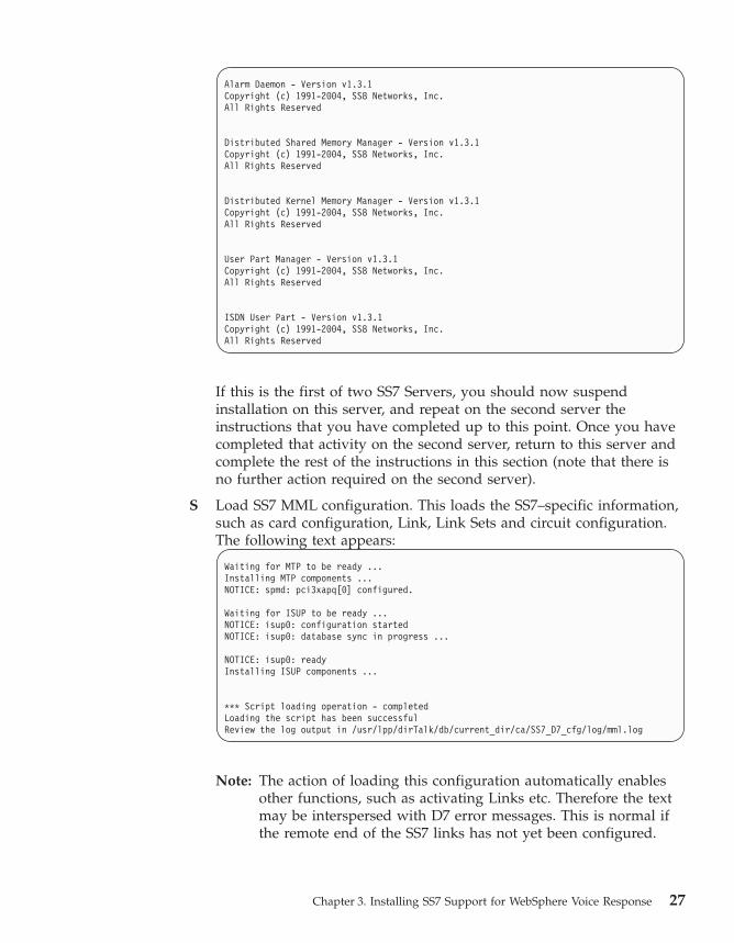
If this is the first of two SS7 Servers, you should now suspend
installation on this server, and repeat on the second server the
instructions that you have completed up to this point. Once you have
completed that activity on the second server, return to this server and
complete the rest of the instructions in this section (note that there is
no further action required on the second server).
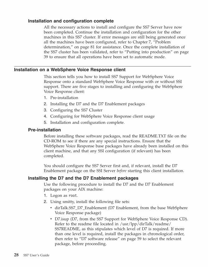
S Load SS7 MML configuration. This loads the SS7–specific information,
such as card configuration, Link, Link Sets and circuit configuration.
The following text appears:
Waiting for MTP to be ready ...
Installing MTP components ...
NOTICE: spmd: pci3xapq[0] configured.
Waiting for ISUP to be ready ...
NOTICE: isup0: configuration started
NOTICE: isup0: database sync in progress ...
NOTICE: isup0: ready
Installing ISUP components ...
*** Script loading operation - completed
Loading the script has been successful
Review the log output in /usr/lpp/dirTalk/db/current_dir/ca/SS7_D7_cfg/log/mml.log
Note: The action of loading this configuration automatically enables
other functions, such as activating Links etc. Therefore the text
may be interspersed with D7 error messages. This is normal if
the remote end of the SS7 links has not yet been configured.
Chapter 3. Installing SS7 Support for WebSphere Voice Response 27
Installation and configuration complete
All the necessary actions to install and configure the SS7 Server have now
been completed. Continue the installation and configuration for the other
machines in this SS7 cluster. If error messages are still being generated once
all the machines have been configured, refer to Chapter 7, “Problem
determination,” on page 81 for assistance. Once the complete installation of
the SS7 cluster has been validated, refer to “Putting into production” on page
39 to ensure that all operations have been set to automatic mode.
Installation on a WebSphere Voice Response client
This section tells you how to install SS7 Support for WebSphere Voice
Response onto a standard WebSphere Voice Response with or without SSI
support. There are five stages to installing and configuring the WebSphere
Voice Response client:
1. Pre-installation
2. Installing the D7 and the D7 Enablement packages
3. Configuring the SS7 Cluster
4. Configuring for WebSphere Voice Response client usage
5. Installation and configuration complete.
Pre-installation
Before installing these software packages, read the README.TXT file on the
CD-ROM to see if there are any special instructions. Ensure that the
WebSphere Voice Response base packages have already been installed on this
client machine, and that any SSI configuration (if relevant) has been
completed.
You should configure the SS7 Server first and, if relevant, install the D7
Enablement package on the SSI Server before starting this client installation.
Installing the D7 and the D7 Enablement packages
Use the following procedure to install the D7 and the D7 Enablement
packages on your AIX machine:
1. Logon as root.
2. Using smitty, install the following file sets:
v dirTalk.SS7_D7_Enablement (D7 Enablement, from the base WebSphere
Voice Response package)
v D7.isup (D7, from the SS7 Support for WebSphere Voice Response CD).
Refer to the readme file located in /usr/lpp/dirTalk/readme/SS7README, as this stipulates which level of D7 is required. If more
than one level is required, install the packages in chronological order,
then refer to “D7 software release” on page 59 to select the relevant
package, before proceeding.
28 SS7 User’s Guide

3. Now copy the relevant Distributed7 license for this machine (see
“Licensing the Distributed7 package” on page 14) into
/usr/ss8/d7/access/etc/license.dat .
The D7 package is installed into the /usr/ss8/d7 directory, and the D7
Enablement package is installed into /usr/lpp/dirTalk.
Configuring the SS7 cluster
This section describes how to locate the necessary configuration for D7. It is
assumed that the guidance provided in “Pre-installation” on page 28 has been
followed and one of the following two scenarios will apply:
1. SS7 Cluster with SSI support.
The D7 Enablement package is already loaded onto the SSI machine and
the SS7itty configuration has been performed. No additional work is
required as the SSI will make all relevant files available to the WebSphere
Voice Response machines.
2. SS7 Cluster without SSI support
The D7 and the D7 Enablement packages are already loaded onto one or
more SS7 Servers and the SS7itty configuration is complete. In this
scenario, follow the instructions below to copy the relevant configuration
files for this machine:
a. Logon as dtuser.
b. Change directory to /usr/lpp/dirTalk/db/current_dir/ca/SS7_D7_cfg,
then use the mkdir command to create a directory with the same name
as this machine (the name returned if you enter the hostname –s
command).
Note: If the /usr/lpp/dirTalk/db/current_dir/ca/SS7_D7_cfg
directory does not exist, create it by running the ss7itty
command, followed by exit.
c. Using ftp, connect to the original SS7 Server on which the SS7itty
command was entered.
d. Using the ftp commands cd and lcd, change both the local and
remote directories to /usr/lpp/dirTalk/db/current_dir/ca/SS7_D7_cfg/AnyMachine.
e. Using the ftp command mget *, copy all the files in this directory.
f. Change both local and remote directories to /usr/lpp/dirTalk/db/current_dir/ca/SS7_D7_cfg/hostname.
g. Using the ftp command mget *, copy all files in this directory.
h. Exit from ftp.
Configuring the AIX machine for WebSphere Voice Response client usage
This section describes how to configure the machine for WebSphere Voice
Response client operation:
Chapter 3. Installing SS7 Support for WebSphere Voice Response 29

1. Login using the dtuser userid. If you are already logged in, logoff and
then login again, because the login profiles will have changed.
2. Start WebSphere Voice Response by entering the command vaeinit. Wait
for the startup process to complete.
3. Returning to the original command prompt window, enter the command
SS7_MAINT, selecting the following options:
S SS7 Server/WebSphere Voice Response client
W Configure machine as a WebSphere Voice Response client.
Once completed, the AIX machine is configured for WebSphere Voice
Response client operation. Two custom servers (SS7_D7 and
D7WVRErrorReport) will have been installed into WebSphere Voice
Response and can be viewed in the Custom Server Manager GUI.
R Return to top level menu
D D7 Operation (Start/Stop)
M Start the D7 package with Alarm Message to screen. The following text
appears:
30 SS7 User’s Guide
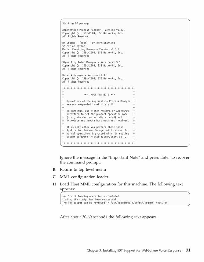
Starting D7 package
Application Process Manager - Version v1.3.1
Copyright (c) 1991-2004, SS8 Networks, Inc.
All Rights Reserved
D7 Status - [init] : D7 core starting
Select an option :
Master Event Log Daemon - Version v1.3.1
Copyright (c) 1991-2004, SS8 Networks, Inc.
All Rights Reserved
Signalling Point Manager - Version v1.3.1
Copyright (c) 1991-2004, SS8 Networks, Inc.
All Rights Reserved
Network Manager - Version v1.3.1
Copyright (c) 1991-2004, SS8 Networks, Inc.
All Rights Reserved
+++++++++++++++++++++++++++++++++++++++++++++++++++
+ +
+ <<< IMPORTANT NOTE >>> +
+ +
+ Operations of the Application Process Manager +
+ are now suspended indefinitely !!! +
+ +
+ To continue, use either MMI/MML or AccessMOB +
+ interface to set the product operation mode +
+ (i.e., stand-alone vs. distributed) and +
+ introduce any remote host machines involved. +
+ +
+ It is only after you perform these tasks, +
+ Application Process Manager will resume its +
+ normal operations & proceed with its routine +
+ system software initialization/start-up ... +
+ +
+++++++++++++++++++++++++++++++++++++++++++++++++++
Ignore the message in the ″Important Note″ and press Enter to recover
the command prompt.
R Return to top level menu
C MML configuration loader
H Load Host MML configuration for this machine. The following text
appears:
*** Script loading operation - completed
Loading the script has been successful
The log output can be reviewed in /usr/lpp/dirTalk/sw/ss7/log/mml-host.log
After about 30-60 seconds the following text appears:
Chapter 3. Installing SS7 Support for WebSphere Voice Response 31

Alarm Daemon - Version v1.3.1
Copyright (c) 1991-2004, SS8 Networks, Inc.
All Rights Reserved
Distributed Shared Memory Manager - Version v1.3.1
Copyright (c) 1991-2004, SS8 Networks, Inc.
All Rights Reserved
Distributed Kernel Memory Manager - Version v1.3.1
Copyright (c) 1991-2004, SS8 Networks, Inc.
All Rights Reserved
Installation and configuration complete
All the necessary actions to install and configure the WebSphere Voice
Response client are now complete. Now continue with any remaining
installations and configurations for other machines in this SS7 cluster. If error
messages are still being generated once all machines have been configured,
refer to Chapter 7, “Problem determination,” on page 81 for assistance. Once
the complete installation of the SS7 cluster has been validated, refer to
“Putting into production” on page 39 to ensure that all operations have been
set to automatic mode.
Installation of a combined SS7 Server and WebSphere Voice Response client
This section tells you how to install SS7 Support for WebSphere Voice
Response on an AIX machine for both SS7 Server and WebSphere Voice
Response client configuration. There are five stages to installing and
configuring the SS7 Server:
1. Pre-installation
2. Installing the D7 and the D7 Enablement packages
3. Configuring the WebSphere Voice Response client and SS7 Cluster.
4. Configuring the AIX machine for WebSphere Voice Response client and
SS7 Server usage.
5. Installation and configuration complete
Pre-installation
Before installing these software package read the README.TXT file on the
CD-ROM to see if there any special instructions.
Installing the D7 and the D7 Enablement packages
Use the following procedure to install the D7 and the D7 Enablement
packages on your AIX machine:
1. Logon with a user id of root.
2. Using smitty, install the following file sets:
32 SS7 User’s Guide

v dirTalk.SS7_D7_Enablement (D7 Enablement, from the base WebSphere
Voice Response package)
v D7.isup (D7, from the SS7 Support for WebSphere Voice Response CD).
Refer to the readme file located in /usr/lpp/dirTalk/readme/SS7README, as this stipulates which level of D7 is required. If more
than one level is required, install the packages in chronological order,
then refer to “D7 software release” on page 59 to select the relevant
package, before proceeding.3. Now copy the relevant Distributed7 license for this machine (see
“Licensing the Distributed7 package” on page 14) into
/usr/ss8/d7/access/etc/license.dat .
The D7 package is installed into the /usr/ss8/d7 directory, and the D7
Enablement package is installed into /usr/lpp/dirTalk, creating a dtuser user
id. This user id has not yet been assigned a password, and so can only be
accessed via the root user id..
Configuring for combined WebSphere Voice Response client and SS7
Cluster
If this is a first machine, refer to Chapter 4, “Configuration using SS7itty,” on
page 43. Otherwise, if this is a second or subsequent machine for the same
cluster, follow the instructions below:
1. Logon as dtuser.
2. Change directory to /usr/lpp/dirTalk/db/current_dir/ca/SS7_D7_cfg,
then use the mkdir command to create a directory with the same name as
this machine (the name returned if you enter the hostname –s command).
Note: If the /usr/lpp/dirTalk/db/current_dir/ca/SS7_D7_cfg directory
does not exist, create it by running the ss7itty command, followed
by exit.
3. Using ftp, connect the original SS7 Server on which the SS7itty command
was entered.
4. Using the ftp commands cd and lcd, change both the local and remote
directories to /usr/lpp/dirTalk/db/current_dir/ca/SS7_D7_cfg/AnyMachine.
5. Using the ftp command mget *, copy all files in this directory.
6. Change both local and remote directories to /usr/lpp/dirTalk/db/current_dir/ca/SS7_D7_cfg/hostname.
7. Using the ftp command mget *, copy all files in this directory.
8. Exit from ftp.
Chapter 3. Installing SS7 Support for WebSphere Voice Response 33
Configuring the AIX machine for WebSphere Voice Response client and
SS7 Server usage
This section describes how to configure the machine for WebSphere Voice
Response client and SS7 Server operation.
1. Logon as dtuser.
2. Enter the command SS7_MAINT, and select the following options:
S SS7 Server/WebSphere Voice Response client
S Configure machine as a combined SS7 Server and WebSphere Voice
Response client.
Once completed the AIX machine is configured for SS7 Server and
WebSphere Voice Response client operation. The status line shown just
before the prompt should show:
<name> is configured for combined D7 WebSphere Voice Response and SS7 Server usage
R Return to top level menu
D D7 Operation (Start/Stop)
M Start the D7 package with Alarm Message to screen. The following text
appears:
34 SS7 User’s Guide
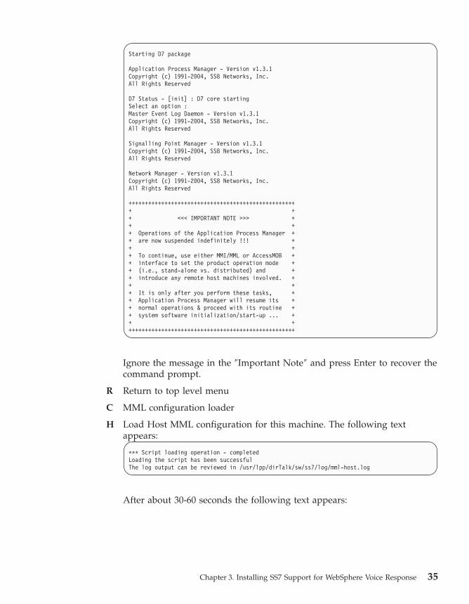
Starting D7 package
Application Process Manager - Version v1.3.1
Copyright (c) 1991-2004, SS8 Networks, Inc.
All Rights Reserved
D7 Status - [init] : D7 core starting
Select an option :
Master Event Log Daemon - Version v1.3.1
Copyright (c) 1991-2004, SS8 Networks, Inc.
All Rights Reserved
Signalling Point Manager - Version v1.3.1
Copyright (c) 1991-2004, SS8 Networks, Inc.
All Rights Reserved
Network Manager - Version v1.3.1
Copyright (c) 1991-2004, SS8 Networks, Inc.
All Rights Reserved
+++++++++++++++++++++++++++++++++++++++++++++++++++
+ +
+ <<< IMPORTANT NOTE >>> +
+ +
+ Operations of the Application Process Manager +
+ are now suspended indefinitely !!! +
+ +
+ To continue, use either MMI/MML or AccessMOB +
+ interface to set the product operation mode +
+ (i.e., stand-alone vs. distributed) and +
+ introduce any remote host machines involved. +
+ +
+ It is only after you perform these tasks, +
+ Application Process Manager will resume its +
+ normal operations & proceed with its routine +
+ system software initialization/start-up ... +
+ +
+++++++++++++++++++++++++++++++++++++++++++++++++++
Ignore the message in the ″Important Note″ and press Enter to recover the
command prompt.
R Return to top level menu
C MML configuration loader
H Load Host MML configuration for this machine. The following text
appears:
*** Script loading operation - completed
Loading the script has been successful
The log output can be reviewed in /usr/lpp/dirTalk/sw/ss7/log/mml-host.log
After about 30-60 seconds the following text appears:
Chapter 3. Installing SS7 Support for WebSphere Voice Response 35

Alarm Daemon - Version v1.3.1
Copyright (c) 1991-2004, SS8 Networks, Inc.
All Rights Reserved
Distributed Shared Memory Manager - Version v1.3.1
Copyright (c) 1991-2004, SS8 Networks, Inc.
All Rights Reserved
Distributed Kernel Memory Manager - Version v1.3.1
Copyright (c) 1991-2004, SS8 Networks, Inc.
All Rights Reserved
User Part Manager - Version v1.3.1
Copyright (c) 1991-2004, SS8 Networks, Inc.
All Rights Reserved
ISDN User Part - Version v1.3.1
Copyright (c) 1991-2004, SS8 Networks, Inc.
All Rights Reserved
If this is the first of two SS7 Servers, you should now suspend installation
on this server, and repeat on the second server the instructions that you
have completed up to this point. Once you have completed that activity
on the second server, return to this server and complete the rest of the
instructions in this section (note that no further action is required on the
second server).
S Load SS7 MML configuration. This loads the SS7–specific information,
such as card configuration, Link, LinkSets and circuit configuration. The
following text appears:
Waiting for MTP to be ready ...
Installing MTP components ...
NOTICE: spmd: pci3xapq[0] configured.
Waiting for ISUP to be ready ...
NOTICE: isup0: configuration started
NOTICE: isup0: database sync in progress ...
NOTICE: isup0: ready
Installing ISUP components ...
*** Script loading operation - completed
Loading the script has been successful
Review the log output in /usr/lpp/dirTalk/db/current_dir/ca/SS7_D7_cfg/log/mml.log
Note: The action of loading this configuration automatically enables other
functions, such as activating Links etc. Therefore the text may be
interspersed with D7 error messages. This is normal if the remote
end of the SS7 link has not yet been configured.
S SS7 Server/WebSphere Voice Response client
36 SS7 User’s Guide

S Configure machine as combined SS7 Server and WebSphere Voice
Response client.
Once completed, the AIX machine is configured for SS7 Server and
WebSphere Voice Response client operation. The status line shown just
before the prompt should show:
<name> is configured for combined D7 WebSphere Voice Response and SS7 Server usage
R Return to top level menu
D D7 Operation (Start/Stop)
M Start the D7 package with Alarm Message to screen. The following text
appears:
Starting D7 package
Application Process Manager - Version v1.3.1
Copyright (c) 1991-2004, SS8 Networks, Inc.
All Rights Reserved
D7 Status - [init] : D7 core starting
Select an option :
Master Event Log Daemon - Version v1.3.1
Copyright (c) 1991-2004, SS8 Networks, Inc.
All Rights Reserved
Signalling Point Manager - Version v1.3.1
Copyright (c) 1991-2004, SS8 Networks, Inc.
All Rights Reserved
Network Manager - Version v1.3.1
Copyright (c) 1991-2004, SS8 Networks, Inc.
All Rights Reserved
+++++++++++++++++++++++++++++++++++++++++++++++++++
+ +
+ <<< IMPORTANT NOTE >>> +
+ +
+ Operations of the Application Process Manager +
+ are now suspended indefinitely !!! +
+ +
+ To continue, use either MMI/MML or AccessMOB +
+ interface to set the product operation mode +
+ (i.e., stand-alone vs. distributed) and +
+ introduce any remote host machines involved. +
+ +
+ It is only after you perform these tasks, +
+ Application Process Manager will resume its +
+ normal operations & proceed with its routine +
+ system software initialization/start-up ... +
+ +
+++++++++++++++++++++++++++++++++++++++++++++++++++
Ignore the message in the ″Important Note″ and press Enter to recover the
command prompt.
R Return to top level menu
C MML configuration loader
Chapter 3. Installing SS7 Support for WebSphere Voice Response 37

H Load Host MML configuration for this machine. The following text
appears:
*** Script loading operation - completed
Loading the script has been successful
The log output can be reviewed in /usr/lpp/dirTalk/sw/ss7/log/mml-host.log
After about 30-60 seconds the following text appears:
Alarm Daemon - Version v1.3.1
Copyright (c) 1991-2004, SS8 Networks, Inc.
All Rights Reserved
Distributed Shared Memory Manager - Version v1.3.1
Copyright (c) 1991-2004, SS8 Networks, Inc.
All Rights Reserved
Distributed Kernel Memory Manager - Version v1.3.1
Copyright (c) 1991-2004, SS8 Networks, Inc.
All Rights Reserved
User Part Manager - Version v1.3.1
Copyright (c) 1991-2004, SS8 Networks, Inc.
All Rights Reserved
ISDN User Part - Version v1.3.1
Copyright (c) 1991-2004, SS8 Networks, Inc.
All Rights Reserved
If this is the first of two SS7 Servers, you should now suspend installation
on this server, and repeat on the second server the instructions that you
have completed up to this point. Once you have completed that activity
on the second server, return to the first server and complete the rest of the
instructions in this section (note that no further action is required on the
second server).
S
Load SS7 MML configuration. This loads the SS7–specific information,
such as card configuration, Link, LinkSets and circuit configuration. The
following text appears:
38 SS7 User’s Guide

Waiting for MTP to be ready ...
Installing MTP components ...
NOTICE: spmd: pci3xapq[0] configured.
Waiting for ISUP to be ready ...
NOTICE: isup0: configuration started
NOTICE: isup0: database sync in progress ...
NOTICE: isup0: ready
Installing ISUP components ...
*** Script loading operation - completed
Loading the script has been successful
Review the log output in /usr/lpp/dirTalk/db/current_dir/ca/SS7_D7_cfg/log/mml.log
Note: The action of loading this configuration automatically enables other
functions, such as activating Links. Therefore the text may be
interspersed with D7 error messages. This is normal if the remote
end of the SS7 link has not yet been configured.
Installation and configuration Complete
All the necessary actions to install and configure the WebSphere Voice
Response client and the SS7 Server are now completed. Now continue with
the installation and configuration for any remaining machines in this SS7
cluster. If error messages are still being generated after all the machines are
configured, refer to Chapter 7, “Problem determination,” on page 81for
assistance. Once the complete installation of the SS7 cluster has been
validated, refer to “Putting into production” on page 39 to ensure that all
operations have been set to automatic mode.
Putting into production
Once the D7 and D7 Enablement packages have been installed, successfully
configured, and have passed testing, there are a number of actions required to
ensure that the packages will auto-restart if the machine is rebooted:
Custom servers
To ensure that the custom servers are started automatically when WebSphere
Voice Response is started, use the Custom Server Manager GUI (which is
accessed from the top level GUI) to check that the IPL Status for both the
custom servers (SS7_D7 and D7WVRErrorReport) are set to AUTOEXEC. This
should be done for all WebSphere Voice Response clients.
D7 package
To ensure that D7 automatically restarts after a system reboot, run the
SS7_MAINT command when logged in as dtuser, and select the menu option
D to enable operation of D7, followed by E to enable D7 to start after system
boot. This action should be performed on all machines in the SS7 cluster.
Chapter 3. Installing SS7 Support for WebSphere Voice Response 39

D7 Alarm Logging
The default operation of the D7WVRErrorReport custom server is to collect
D7 alarms that are generated by the machine on which it is running. For those
SS7 Servers where WebSphere Voice Response is not installed, the custom
server is not available to collect these errors. To ensure that D7 Alarms are
collected and stored into the WebSphere Voice Response system, one or more
WebSphere Voice Response systems can be selected to collect D7 Alarms from
the SS7 Servers.
This operation involves instructing the D7WVRErrorReport custom server to
register itself globally in the SS7 Cluster, and thereby be able to collect D7
alarms from other machines. Note that a custom server that is globally
registered in this way does not collect D7 Alarms from other WebSphere Voice
Response machines if they are running D7WVRErrorReport themselves, as a
local custom server takes precedence.
To enable a D7WVRErrorReport custom server for global registration, follow
the menu path below from the top level menu in the WebSphere Voice
Response GUI.
1. From the top-level WebSphere Voice Response menu, click Applications.
2. From the drop-down menu, select Custom Servers.
3. From the custom server list, double-click D7WVRErrorReport.
4. Click File
5. Click Properties
The Properties panel is displayed, showing six separate windows. In the top
left window, labelled main () args, ensure that the characters –r and –g appear
on separate lines, as shown in Figure 6 on page 41.
40 SS7 User’s Guide

Figure 6. The Properties panel for the D7WVRErrorReport custom server
Chapter 3. Installing SS7 Support for WebSphere Voice Response 41

42 SS7 User’s Guide

Chapter 4. Configuration using SS7itty
The section covers the use of the SS7itty configurator, which is based on the
architecture of the AIX smitty facility. It takes the requirements of the SS7
Cluster and constructs the relevant configuration files.
Preparation
The first stage is to collect the relevant information together as described in
Chapter 2, “Planning,” on page 13. The SS7itty only needs to be run on one
machine in the SS7 Cluster as it creates files for all the machines. If a
WebSphere Voice Response SSI server is present in the cluster, use this to run
SS7itty, as the configuration is then automatically distributed to the other
WebSphere Voice Response machines (although manual copying to the SS7
Servers is required).
If no SSI is present, select one of the SS7 Servers.
Running SS7itty
To run SS7itty, first log on to the selected machine as dtuser, and enter the
command SS7itty. The follow screen appears:
SS7 Configuration
Move cursor to desired item and press Enter.
Configure Environmental Conditions
Configure AIX Systems
Configure SS7 Server
Configure WVR Client
Configure SS7 Links
Configure SS7 Route Sets
Configure SS7 Trunks to WVR Trunks
Generate SS7 Configuration Files
Export SS7 Configuration
Import SS7 Configuration
F1=Help F2=Refresh F3=Cancel F8=Image
F9=Shell F10=Exit Enter=Do
The natural progression is to go to each configuration option in turn and then
perform the Generate (after pressing Enter). The Export/Import function,
which is described later, enables backing-up of data and recovery of previous
configurations. The key operations are the same as for the AIX smitty
command.
© Copyright IBM Corp. 2001, 2008 43

On most submenus, there are four options:
Add Creates a new entry
Change/Show Modifies or displays the details of an existing
entry
Delete Deletes an entry
Show Shows all the current entries
As an example, the submenu for Configure AIX Systems is shown below:
Configure AIX Systems
Move cursor to desired item and press Enter.
Add an AIX Computer
Change / Show Characteristics of an AIX Computer
Delete an AIX Computer
Show Summary of AIX Computers
F1=Help F2=Refresh F3=Cancel F8=Image
F9=Shell F10=Exit Enter=Do
The following sections provide more detail about each of the choices available
from the SS7itty main menu:
Configure Environmental Conditions
The following screen is displayed:
Change / Show Characteristics of an SS7 Environment
Type or select values in entry fields.
Press Enter AFTER making all desired changes.
[Entry Fields]
* SS7 Variant [ANSI/T1 GENERIC (2000)] +
* SS7 Configuration Pack [Standard] +
F1=Help F2=Refresh F3=Cancel F4=List
F5=Reset F6=Command F7=Edit F8=Image
F9=Shell F10=Exit Enter=Do
The SS7 Environment defines the operational conditions for the SS7 Cluster.
There are two configurable options, which can be selected with the F4 key:
SS7 Variant
Defines the SS7 variant of the connecting network
44 SS7 User’s Guide

SS7 Configuration Pack
Handles the special conditions that are outside the SS7 variant. From
the options that are displayed, unless you have been directed
otherwise, select Standard
Configure AIX Systems
The Configure AIX Systems submenu is used to define all the machines
within the SS7 Cluster. When the Add option is selected, the following screen
is displayed:
Add an AIX Computer
Type or select values in entry fields.
Press Enter AFTER making all desired changes.
[Entry Fields]
* Computer Name []
* First TCPIP Address (15 char LAN name) []
Second TCPIP Address (15 char LAN name) []
F1=Help F2=Refresh F3=Cancel F4=List
F5=Reset F6=Command F7=Edit F8=Image
F9=Shell F10=Exit Enter=Do
Review the information collected in the table entitled ″AIX machines″ in
Appendix A, “Sample forms for recording information,” on page 101, and
enter the data as follows:
Computer Name
Name of the machine
First TCPIP Address
The primary IP address
Second TCPIP Address
The secondary IP address (this is optional)
For any additional AIX computer entries, you can either modify the previous
entry or start a new one from the submenu.
On completion, review the information that is displayed when you select the
Show Summary option
Chapter 4. Configuration using SS7itty 45

Configure SS7 Server
This submenu is used to further define which AIX Computers are to be SS7
Servers. The following screen appears when you select the Add option:
Add an SS7 Server
Type or select values in entry fields.
Press Enter AFTER making all desired changes.
[Entry Fields]
* SS7 Server (AIX Computer name) [] +
* SS7 Original Point Code (x-x-x or 0x???) []
F1=Help F2=Refresh F3=Cancel F4=List
F5=Reset F6=Command F7=Edit F8=Image
F9=Shell F10=Exit Enter=Do
After reviewing the information collected in the Table entitled AIX
MACHINES in Appendix A, “Sample forms for recording information,” on
page 101, for each entry of Machine Type SS7 Server name, enter the
following data.
v SS7 Server - select the Computer Name from the list that appears when you
press F4. If the name is not present, return to the Configure AIX System
menu, and review the machine names.
v SS7 Original Point – enter the OPC as defined in the Originating Point
Code table.
On completion, review the information that is displayed when you select the
Show Summary option
Configure WebSphere Voice Response client
This submenu is used to further define which AIX Computers are to be
WebSphere Voice Response clients. The following screen appears when you
select the Add operation:
Add a WebSphere Voce Response Client
Type or select values in entry fields.
Press Enter AFTER making all desired changes.
[Entry Fields]
* WebSphere Voce Response Client (AIX Computer name) [] +
* Telephone Trunks Attach to Computer (1 .. 16) []
* Voice Bearer card type [DTXA/DTXA2] +
F1=Help F2=Refresh F3=Cancel F4=List
F5=Reset F6=Command F7=Edit F8=Image
F9=Shell F10=Exit Enter=Do
46 SS7 User’s Guide

Review the information that has been collected in the AIX MACHINES table,
and for each entry of machine type WebSphere Voice Response Client, enter
the following data:
v WebSphere Voice Response Client. Select the Computer Name list that is
generated by pressing F4. If the name is not present, return to the
Configure AIX System sub menu and review the machine names.
v Telephone Trunks. This defines the trunks within the WebSphere Voice
Response system that are to be allocated to SS7. For example, if all 16
trunks are to be allocated, enter 1-16. For a fragmented selection, for
example where trunks 9 through 14 are used for ISDN, enter either
1-8,15,16 or 1-8,15-16.
v Voice Bearer card type. Currently there is only one possible option,
DTXA/DTTA.
On completion, review the information that is displayed when you select the
Show Summary option.
Configure SS7 Links
This submenu defines the Links, or connections to the SS7 network from the
SS7 Servers. To assist you, use the information collected in the Signaling links
table in Appendix A, “Sample forms for recording information,” on page 101.
The following screen appears when you select the Add operation:
Add an SS7 Link
Type or select values in entry fields.
Press Enter AFTER making all desired changes.
[Entry Fields]
* Link Name [Network-01]
* SS7 Server [] +
* CardType [pci3xapq HAX50PCGEN 4 Ports E1/T1] +
* CardIndex [0] +
* PortIndex [1] +
* Timeslot [16]
* SLC [0]
* Priority [0]
* ClockSource [Other] +
F1=Help F2=Refresh F3=Cancel F4=List
F5=Reset F6=Command F7=Edit F8=Image
F9=Shell F10=Exit Enter=Do
Enter the following data for each entry in the Signaling links table:
Link Name
This is the name given to this Link or connection. SS7itty creates a unique
name for you, which you can override. Note that to get a unique name
created when creating subsequent Links, you must reenter the submenu.
Chapter 4. Configuration using SS7itty 47
SS7 Server
Use the list generated when you press F4 to select a predefined SS7
Server. If the machine name is not present, return to the Configure SS7
Server menu and review information entered.
CardType
Use the information entered into the table under SS7 Adaptor to make a
selective choice.
Card Index
Use the Instance value to define the card index. If only one card is
present, set this to zero.
PortIndex
This is the value entered in the table as Port. The valid range of values
will be dependent on the CardType that is selected.
Timeslot
This is the value that appears as Timeslot in the table. Valid values are
0-23 for T1 and 1-31 for E1.
SLC
This is the value that is listed under SLC. This will have been defined for
the Network operator.
Priority
This value needs to be unique for each connection. Enter a value starting
from 0.
Clocksource
The adapter needs to take a clock source from one of the connections. For
the first connection on an adapter, select Line, and then select Other for
any subsequent entries that are using the same adapter. In the rare case
when the Network is not supplying a stable clock, replace Line with
Local.
On completion, review the information that is displayed when you select the
Show Summary option.
Configure SS7 Link sets
This submenu defines the grouping of the Links that have the same
Destination Point Code. Use the information collected in the Signaling links
table from Appendix A to create Link Sets. In most cases there will be only
one Link Set. The following screen appears when you select the Add
operation:
48 SS7 User’s Guide

Add an SS7 LinkSet
Type or select values in entry fields.
Press Enter AFTER making all desired changes.
Entry Fields]
* SS7 Link Set Name NetworkB]
* SS7 Link 1 [] +
SS7 Link 2 [] +
SS7 Link 3 [] +
SS7 Link 4 [] +
SS7 Link 5 [] +
SS7 Link 6 [] +
SS7 Link 7 [] +
SS7 Link 8 [] +
* SS7 Destination Point Code[x-x-x or hex] [] +
F1=Help F2=Refresh F3=Cancel F4=List
F5=Reset F6=Command F7=Edit F8=Image
F9=Shell F10=Exit Enter=Do
Complete one of these screens for each different DPC entry in the Signaling
links table, as follows:
v Link Set Name. The name given to this Link Set. SS7itty create a unique
name for you, which you can override. Note that when you create
subsequent Links, to ensure a unique name you must reenter the submenu.
v SS7 Link. Use the list that is generated by pressing F4 to select predefined
Links.
v Destination Point Code. Enter the value of the DPC from the table.
On completion, review the information that is displayed when you select the
Show Summary option.
Configure SS7 Route Sets
This submenu defines the routing to the switches via the Link Sets. Use the
information collected in the Route Set table from appendix A. The following
screen appears when you select the Add operation:
Add an SS7 Route
Type or select values in entry fields.
Press Enter AFTER making all desired changes.
[Entry Fields]
* SS7 Route Set Name [ ]
* Switch Destination Point Code[x-x-x or hex] []
* SS7 LinkSet 1 [] +
SS7 LinkSet 2 [] +
SS7 LinkSet 3 [] +
SS7 LinkSet 4 [] +
* SS7 Bearer Trunks associated with this Route Set []
Chapter 4. Configuration using SS7itty 49

Complete one of these screens for each Route Set in the Route Set table, as
follows:
v Route Set Name. The name given to this Route Set. SS7itty creates a unique
name for this, which you can override. Typically, this would be the name of
the switch. Note that when you create subsequent Route Sets, you must
reenter the submenu to ensure that you assign a unique Route Set Name.
v Switch Destination Point Code. Enter the value of the DPC from the table.
v LinkSets. To select a predefined Link Set, use the list that is generated by
pressing F4.
v Bearer Trunks. This is a list of trunks that are being supplied by the
Network under this DPC.
On completion, select the Show Summary option, and review the information
that is displayed.
Configure SS7 trunks to WebSphere Voice Response trunks
This submenu defines the Voice Bearer interconnections between the network
and the WebSphere Voice Response systems. Use the information collected in
the Trunk table to create entries. The following screen appears when you
select the Add operation:
Add an SS7 Trunk
Type or select values in entry fields.
Press Enter AFTER making all desired changes.
[Entry Fields]
* SS7 Trunk (Route Set name) [] +
* SS7_Trunks []
* WebSphere Voice Response Client [] +
* WebSphere Voice Response Trunks []
F1=Help F2=Refresh F3=Cancel F4=List
F5=Reset F6=Command F7=Edit F8=Image
F9=Shell F10=Exit Enter=Do
Complete one of these screens for each entry in the TRUNK table, as follows:
v SS7 Trunk (Route Set name). Use the F4=List option to select a predefined
SS7 Trunk or Route Set name.
v SS7 Trunks Select a range of network trunks to be used in this entry of the
interconnect.
v WebSphere Voice Response Client . Use the F4=List option to select a
predefined WebSphere Voice Response client.
v WebSphere Voice Response Trunks . Select a range of WebSphere Voice
Response trunks to be used in this entry of the interconnect.
50 SS7 User’s Guide

On completion, review the information that is displayed when you select the
Show Summary option.
Generate SS7 Configuration Files
When all the necessary information has been entered into SS7itty, you can
generate the configuration. To perform this task, select the Generate SS7
Configuration Files option from the top level menu. For a successful
generation, the screen that is displayed should look similar to the one below:
COMMAND STATUS
Command: OK stdout: yes stderr: no
Before command completion, additional instructions may appear below.
Stage 1: Load environment information.
Stage 2: Check configuration association.
Stage 3: Check Trunk usage.
Stage 4: Check SS7 adapter card usage.
***** Checking data has been successful.
Stage 5: Creating WebSphere Voice Response Client files.
Stage 6: Creating Distributed7 files.
Stage 6a: Machine Mercury
Stage 6b: Machine Venue
Stage 6c: Machine Mars
F1=Help F2=Refresh F3=Cancel F6=Command
F8=Image F9=Shell F10=Exit /=Find
n=Find Next
The first four stages of the process check the form of the entered data. The
last two stages perform the actual generation of the configuration files. If
problems are found during the checking stage, a screen is displayed similar to
the one below:
Chapter 4. Configuration using SS7itty 51

COMMAND STATUS
Command: failed stdout: yes stderr: no
Before command completion, additional instructions may appear below.
Stage 1: Load environment information.
Stage 2: Check configuration association.
Stage 3: Check Trunk usage.
---------------- SS7 Trunks to WebSphere Voice Response Trunks/SS7 Trunks -----------
Error: Trunk 17 is present in the following RouteSets/Clients
RouteSet/Client: NetworkA/Venus
RouteSet/Client: NetworkA/Mars
Remedy: Return to the "SS7 Trunks to WebSphere Voice Response Trunks" change screen, select one of
The of two RouteSets/Clients and review the SS7 Trunks selected.
--------------------------------------------------------------------------------------
The configuration generation has been aborted.
F1=Help F2=Refresh F3=Cancel F6=Command
F8=Image F9=Shell F10=Exit /=Find
n=Find Next
In this example, Network Trunk 17 has been defined for connection with two
WebSphere Voice Response systems. Generation has terminated at stage 3,
reporting this problem, together with directions about how to possibly rectify
the situation.
Importing or exporting an SS7 configuration
The Export option on the top level menu allows the current information to be
written to a file. These files are stored in /usr/lpp/dirTalk/db/current_dir/ca/SS7_D7_cfg/archive and have a file extension of .arc.
Information can similarly be imported from previously exported files using
the Import option and the F4=List option.
Pack Configuration
1. Login to WebSphere Voice Response.
2. From the WebSphere Voice Response Welcome window, select
Configuration —> Pack Configuration —> Change.
3. Make the following changes to each of the packs indicated:
a. Set Trunk Parameters to CCS-SP.
b. Set Line Signaling to SS7-ISUP. For optimum SS7 performance, put all
the channels on each pack in a single group.
c. Check the Save check-box for each pack that has been modified.
d. Click File —> Save.
52 SS7 User’s Guide

e. Confirm the save.
f. Click File —> Close to return to the Welcome window.
Note: You need to restart WebSphere Voice Response for the new pack
configuration to take effect.
For detailed about information on pack configuration see the WebSphere Voice
Response for AIX: Configuring the System book.
Chapter 4. Configuration using SS7itty 53

54 SS7 User’s Guide

Chapter 5. Managing and Monitoring SS7 Support for
WebSphere Voice Response
This part of the book describes how to manage Distributed7 after you have
installed it, and how to monitor activity.
SS7_MAINT – the general maintenance utility
The SS7_MAINT is a general purpose facility to run other commands that are
associated with SS7 Support for WebSphere Voice Response. This command
has been designed to simplify the SS7 maintenance by having the most
frequently-used commands accessible from a central point. The basic
operation of the menu structure is a single letter selection from a menu choice
displayed on the screen. The following options are available on all levels:
R Return to previous level
Q Quit the SS7_MAINT utility (this is not published on all menus but is
always available for use)
? Redisplay the menu option from the current level
<Enter>
Redisplay the current prompt. Some menu levels redisplay an active
status, so using <Enter> without selecting an option can be useful in
monitoring a changing status.
The top-level menu for SS7_MAINT is shown below:
© Copyright IBM Corp. 2001, 2008 55

WebSphere Voice Response
Signaling System #7
Maintenance Program
Top Level Menu
--------------------------------------------------------------------------------
E - Enablement Operation (Start/Stop).
D - D7 Operation (Start/Stop)
C - MML configuration loader
H - Housekeeping
M - D7 Maintenance programs
S - SS7 Server/WVR Client
I - iFix Loading
F - Fault Finding
V - D7 software release
? - Redisplay these options.
Q - Quit this program
Select an option :
The functionality of each of the options is described in the following sections:
Enablement Operation
This menu handles the starting and stopping of the SS7_D7 signaling custom
server. These same operations can be performed from the WebSphere Voice
Response Custom Server Manager GUI. This menu has an active prompt that
indicates the current execution state of the SS7_D7 custom server.
The menu has two options to start and to stop the custom server. When one
of these options is selected, the prompt returns immediately without
confirming the action. However, the status can be monitored by periodically
pressing Enter to update the status.
D7 Operation
This menu handles the starting and stopping of the Distributed7 package, and
has an active prompt indicating the current state of the package. The menu
options are:
S Start the D7 package in silence mode, without any alarm message
being copied to screen. This is the default method of starting D7
unless you have just completed installation or are fault-finding.
M Start the D7 package with alarm message being copied to screen. This
method is useful when first installing D7 or fault-finding.
T Terminate the D7 package. This initiates the sequence to close down
the D7 package.
56 SS7 User’s Guide

E This enables automatic start of the D7 package following a system
startup.
D This disables automatic start of the D7 package following a system
startup. The D7 package must be started by hand (using SS7_MAINT).
Note: The options S, M, and T initiate the command sequence, and the return
of the prompt does not imply the sequence has completed. The current
state of the D7 package can be monitored by periodically pressing Enter
to update the active prompt.
MML Configuration Loader
This handles the options around MML (the D7 configuration database), and
should be used when initially configuring the SS7 cluster or updating.
Possible options are:
H Install the Host MML configuration for this machine from the
mml-host file generated by SS7itty.
S Load the SS7 configuration for the whole SS7 Cluster from the
mml-ss7 file generated by SS7itty.
F Remove the MML database from the current machine, ready to receive
a new copy of the Host MML and SS7 MML.
Notes:
1. The option cannot be performed when the D7 package is running.
2. The root password will be requested in order to gain access to the
root-owned database files.
B Backup the currentMML configuration by creating the file
/tmp/D7-dbBackup.
Z Restore a previously backed-up MML configuration. It overwrites the
current configuration in the MML database with the data stored in file
/tmp/D7-dbBackup.
HouseKeeping
This menu option allows the monitoring and control of the Log/Event and
Trace files generated by the SS7/D7 Enablement custom server. On initial
entry to this submenu the current Log/Error and Trace files are listed. The
options are as follows:
A Delete all the listed files.
E Deletes only the error files listed.
V Delete only the event files listed.
T Deletes the SS7 trace file.
D Rescreen the file information list on entry.
Chapter 5. Managing and Monitoring SS7 Support for WebSphere Voice Response 57

D7 Maintenance programs
This submenu gives access to a number of system health-monitoring programs
that are used to verify the D7 package. Possible options are:
C Show the SS7 card that is present in the current machine. It runs the
D7 command getcfg and shows its output. getcfg shows the state and
presence of the SS7 adapters in the current machine.
P Show the current D7 processes that are running. It runs the D7
command apm_ps, which identifies which D7 processes are running
on the current machine.
O Show the status of the OSI components. It initiates the D7 command
AccessMonitor, which shows all the currently active machines within
the SS7 cluster, and what options are currently running. Note
AccessMonitor is a GUI, for further information refer to “SS8
commands” on page 66.
L Show the status of the SS7 Links by initiating the D7 command
AccessStatus, which shows the status of the Link in the current SS7
cluster, and the currently message capacity. For more information on
this command refer to “SS8 commands” on page 66.
D Show the D7 interconnect status by running the D7 command
ebs_showlink. The output shows the connected machine on the SS7
cluster and the available SS7 adapters. For more information on this
command refer to “SS8 commands” on page 66.
M Run the ss7view –circuit command, showing the current status of the
associated circuits from this machine. Note that this option is available
only on WebSphere Voice Response client machines. For more
information on this command refer to “ss7view – D7 Enablement
monitoring tool” on page 60.
SS7 Server/WebSphere Voice Response client
This menu handles the options for configuring a machine for either server or
client operation. Possible options are as follows:
S Configure the current machine for SS7 Server operation
W Configure the current machine for WebSphere Voice Response client
operation. Also use this option for configuring this package on a SSI
machine.
I Configure a WebSphere Voice Response client connected to a single
system image.
C Configure a combination of a WebSphere Voice Response client and an
SS7 Server in the same machine.
58 SS7 User’s Guide

iFix Loading
This option is used to install a temporary software fix for the D7 package.
Should a software correction be issued, copy the file to /tmp/iFix and select
this option. The iFix file is in TAR format and contains a script to run the
necessary file-copying of the supplied corrections.
Fault Finding
This menu is designed to assist when using Chapter 7, “Problem
determination,” on page 81 from this book. During the identification of the
root cause of problem, you may be asked to run certain options and act on the
output. Options for this menu are as follows:
1 D7 Network Check. Gives the output from the D7 command
ebs_showlink
2 D7 Process Check. Gives the output from the D7 command ebs_ps
3 D7 Card Check. Gives a status report of the SS7 adapters.
ss7problem
the options S, L, and D each run the ss7problem command on level 1,
2 and 3 respectively. Each of these options generates data that can be
sent to IBM to assist in problem determination.
D7 software release
This menu provides control over which release Distributed 7 package is to be
run. On selection of this option a screen similar to below will be shown:
--------------------------------------------------------------------------------
WebSphere Voice Response
Signaling System #7
Maintenance Program
D7 Release Menu
--------------------------------------------------------------------------------
Current active release: 1.3.1.7
Available releases: 1.3.1.0
1.3.1.7
C - Change active release
? - Redisplay these options.
R - Return to top level menu
Select an option :
The currently-selected release is shown, followed by the available releases.
The readme in /usr/lpp/dirTalk/readme/SS7.README defines the release
that you should select. To change the selected release, use option C, and then
Chapter 5. Managing and Monitoring SS7 Support for WebSphere Voice Response 59

select the required release from the subsequent menu. As this changes
elements within the Distributed7 package, you must enter the root password
before you can proceed.
Notes:
1. Before changing a release, ensure that Distributed7 is not running; if it is,
it will be terminated.
2. A question regarding the copy MML database might appear at this stage;
if so, you should normally respond with ″yes″, as this is a new or upgrade
installation.
ss7view – D7 Enablement monitoring tool
The ss7view command is a multi purpose tool for monitoring the operation of
the SS7_D7 Custom Server. It has the following functions:
1. Monitoring the service state and call connection states of all circuits
2. Monitoring the internal event log
3. Monitoring the SS7 and WebSphere Voice Response message flows
4. Control event capture through error message triggers
5. Monitoring call statistical information
6. Translating release cause code
7. Providing information about the signaling state table
The following sections describe how to use the ss7view command for each of
the functions in the above list.
ss7view – help options
If you run ss7view without any argument, or with the –help argument, the
following screen is displayed, listing all the possible operations and how to
view help information for each of them :
Prompt> ss7view -help
ss7view :: SS7_D7 monitoring tools
----------------------------------
For help on ....
SS7-D7 Event ............. Type ss7view -help event
SS7 ISUP Messages ........ Type ss7view -help message
Monitors circuits ........ Type ss7view -help circuit
SS7 Stats ................ Type ss7view -help stats
Event triggering ......... Type ss7view -help trigger
Trace level monitoring ... Type ss7view -help trace
Cause Code explanation ... Type ss7view -help cause
Information .............. Type ss7view -help info
ss7view – monitor circuits
This monitor circuit option shows the current service state and call state of all
circuits on the current WebSphere Voice Response client. To use it,
60 SS7 User’s Guide

enter ss7view –circuit [<trunks>] The [<trunks>] is optional, and defines
how many trunks to display at one time. The default is 16. A typical screen
might look like this:
SS7 Circuit Status on b80h []
│0 2 4 6 8 10 12 14 16 18 20
────┼─────────────────────────────────────────────
1│*
2│
3│
4│
5│
6│
7│
8│
9│
10│
11│
12│
13│
14│
15│
16│
────┴────────────────────────────────────────────
Selected Circuit ... 0
Call state = answ
Near End Service state = Ubk
Far End Service state = Ubk
Press Q to quit
The central area of the screen shows a real-time updating interpretation of the
current state of each circuit. This is ordered in rows of trunks and columns of
circuits within trunks. Note that the number of the column is 0-23 for T1 and
0-31 for E1. The E1 display will show the letters F and S in the zero and
sixteenth column. This is to indicate the frame and signaling timeslot.
Within the table a single character is used to denote the current state. For an
SS7 cluster with more trunks than that are being displayed, others can be
shown by either using the up and down cursors keys or the Page Up and
Page Down keys to scroll through the display.
Although all the circuits of the SS7 cluster are displayed, only those
pertaining to this client will show their call state. Trunks for other WebSphere
Voice Response clients show only their redundancy state relative to this client.
The lower part of the screen shows details of an individual circuit. The CIC
value of the circuit being viewed is shown in the first line. This can be
selected using the cursor keys to move the reversed video character to the
desired circuit. The other three lines show the internal states of Call, Near End
Service and Far End Service. Refer to “ss7view –info” on page 65 for a legend
to interpret the characters and phrases that are displayed on this screen.
Chapter 5. Managing and Monitoring SS7 Support for WebSphere Voice Response 61

ss7view –event
The SS7_D7 custom server is based on a state table design (this is different to
a WebSphere Voice Response state table). Each time a message is received, the
SS7_D7 state table engine is run to generate the required reaction and also log
events. These events are logged in shared memory which can in turn be read
by ss7view.
The simplest form of ss7view –event shows all logged events since SS7_D7
started running, or when it wrapped. Other options are as follows:
–t Tail event buffer. Once the current events have been displayed,
ss7view continues to monitor the event buffer and display new events
as they are detected. Use Ctrl + C to exit from this mode
–c <cic> or –c <cic>–<cic>
Filters the event display so that only events relating to the <cic> or
the <cic>–<cic> range are displayed.
–s Use with the –c option to re-enable displaying of non cic-based
events.
–R <filename>
Copies the event buffer in raw mode into a named file for later
processing. This option is used in the ss7view – trigger option (see
“ss7view –trigger” on page 63).
–f <filename> or –f <filename>,<state table>
instead of using the current event buffer, this option processes data
stored in <filename> that was previously created with the –R option.
The additional <state table> is for machines that are not currently
using the same state table as the originating machine.
ss7view –message
The ss7view –message option uses the event information to interpret the
message flows through SS7_D7 custom server, WebSphere Voice Response and
SS7 Stack. Below is an example output from ss7view for a single inbound call
on CIC 0.
13:29:38.264:0000: IAM/ISUP_SETUP[1234] ---------->>
13:29:38.265:0000: SL_CALL_SETUP_IND ---------->>
13:29:38.265:0000: <<---------- ACM/ISUP_OGC_SELECTED
13:29:38.265:0000: <<---------- ACM/ISUP_ALERT
13:29:38.268:0000: <<---------- SL_CALL_ANSWER_REQ
13:29:38.268:0000: SL_CALL_ANSWER_CNF [SL_REPLY_SUCCESS] ------->>
13:29:38.269:0000: <<---------- ANM/ISUP_SETUP
.......
13:29:41.846:0000: <<---------- SL_CALL_TERMINATE_REQ
13:29:41.846:0000: <<---------- REL/ISUP_RELEASE[Cause:CSV_NORMALCALLCLR]
13:29:41.861:0000: RLC/ISUP_RELEASE ---------->>
13:29:41.862:0000: SL_CALL_TERMINATE_CNF [SL_REPLY_SUCCESS] ---->>
The information show is:
62 SS7 User’s Guide

hh:mm:ss:mmm
The time stamp of the event down to milliseconds
cccc CIC number of circuits
Message flows
From left to right, these are:
v Network/SS7 Stack
v SS7_D7 custom server
v WebSphere Voice Response
The arrows show the direction that the message travels. In the above example,
the first line shows IAM message being sent from the SS7 Stack to the
SS7_D7. The next shows that SS7_D7 has converted this message into a
SL_CALL_SETUP_ID message, which is then passed onto WebSphere Voice
Response, and so on.
The following arguments are available:
–t After displaying the current message, monitor the event buffer for
new messages, and display when detected. Use Ctrl + C to exit from
this mode.
–<cic> filters events to show only messages for the given CIC.
ss7view –trigger
This option allows ss7view to define to SS7_D7 which errors, when detected,
should cause the execution of a predefined command. This is generally used
to capture event-buffer information prior to an error being detected. The
collected information can then be subsequently examined to discover the
reason for the error.
The command that is run is defined in the Logevent.cfg (see “Logging and
event file” on page 109 for further information). The ss7view –trigger option
can define and redefine which errors trigger a dump of the event buffer. The
format of the command is ss7view -trigger <trigger options>, with possible
options as follows:
d<event>
Deletes event <event>
i<event>=<times>
Inserts event <event> to trigger a maximum of <times> times.
r<event>
Refreshes event <event>. The maximum <times> is reset.
u<event>=<times>
Updates event <event> as that the maximum time is <times>
Chapter 5. Managing and Monitoring SS7 Support for WebSphere Voice Response 63

s Shows the setting of all current active triggers.
For example ss7view -trigger i30000=2d30002s performs the following:
Insert event 30000 to trigger twice
Delete event 30002
Show the resulting setting
Note: only errors within the range 30000 and 31999 that are generated by
SS7_D7 can be used as triggers.
ss7view -trace
The ss7view –trace option controls a secondary tracing facility that involves
writing text messages to a file. This form of tracing can be used to identify
specific problem areas in very low call volumes and is not recommended for
general use. An example of such a use would be to identify message and
parameter problems in SS7 when used on a new or different variant of an SS7
network. The command takes the format ss7view -trace <option>, where the
options are list below. Each option is used with either a + or – preceding
them. The + and - mean enable and disable the mode respectively.
A Action class
i Information class
z Maintenance
S Subsystem (AIX operations) class
m WebSphere Voice Response and ISUP messages
t Dump of table information
c clear – disable all modes previous enabled
d display the currently enabled modes
For example, ss7view -trace +iA-td :
Enables information
Enables actions
Disables tables
Displays current settings.
Trace information is appended to /usr/lpp/dirTalk/db/current_dir/oam_log/SS7/SS7-Trace.
ss7view –stat
The SS7_D7 custom server can collect some basic statistical information about
call rates and process waiting times. The enablement of this feature and its
sampling rates are defined in the LogEvent.cfg file (see “Logging and event
file” on page 109 for more information). To run the command enter ss7view
64 SS7 User’s Guide

–stat. This command continuously updates the screen with new information
as each time period is complete. To exit this program use Control + C.
The columns are defined as follows:-
Time Range
The timestamp for the end of the period just sampled.
Busy Ratio
A rough calculation of the ratio of time spent waiting for messages
against the time processing messages. A typical value of 14% indicates
that in one second, approximately 1/7 of that second was spent
processing messages. This is a useful indicator to show when the
SS7_D7 custom server is not getting sufficient processing time.
Network IAM
A count of inbound call setup messages.
Network REL
A count of release messages from the network.
Network ABRT
A count of inbound calls that have been aborted (calls that did not
reach the answer state).
WebSphere Voice Response IAM
A count of outbound call setup messages.
WebSphere Voice Response REL
A count of release messages generated by WebSphere Voice Response.
WebSphere Voice Response ABRT
A count of outbound calls that have been aborted.
BHCA A rough projection of the Busy Hour call attempts. It is a calculation
of the number of call setups over the current sample period and the
previous five sample periods as if consecutive over an hour.
BHCC A rough projection of the Busy Hour call completion. This is
calculated in the same way as BHCA, but is based on the release
messages.
ss7view –info
Information that relates to the Signaling State Table can be displayed through
the ss7view –info option.
Enter ss7view –info –p to display the current protocol and variant
information of the loaded Signaling State Table.
Enter ss7view –info –c to display a legend of the possible circuit states as
shown in ss7view –circuit, with brief and full descriptions.
Chapter 5. Managing and Monitoring SS7 Support for WebSphere Voice Response 65

ss7view –cause <name/value>
This option interprets a Release cause code into a full description. The option
takes a single argument of either a numerical value or a mnemonic label. For
example ss7view –cause 16 or ss7view –cause CSV_NORMALCALLCLR.
All mnemonics start with the letters CSV and may appear in other ss7view
options.
SS8 commands
This section describes the following SS8 commands:
v AccessMonitor
v AccessStatus
v ebs_showlink
AccessMonitor
AccessMonitor is a D7 GUI utility that monitors the operational states of the
various components within the D7 SS7 cluster. It can be run either from
SS7_MAINT (option M, then O) or from the command line by entering
AccessMonitor 0 &.
The example screen below shows a three machine configuration. b80c and
b80e are both WebSphere Voice Response clients and have the D7 base
processes running – denoted in green. Machine h80a has been configured for
SS7 Server operation and has the MTP-L3 and ISUP layer processes running.
The SS7 Server contains a configured SS7 adapter with MTP-L2 running.
If a process stops running or has problems, the corresponding panel on the
screen changes to red. If a machine stops running D7, all of its boxes change
to grey.
Figure 7. The AccessMonitor screen
66 SS7 User’s Guide
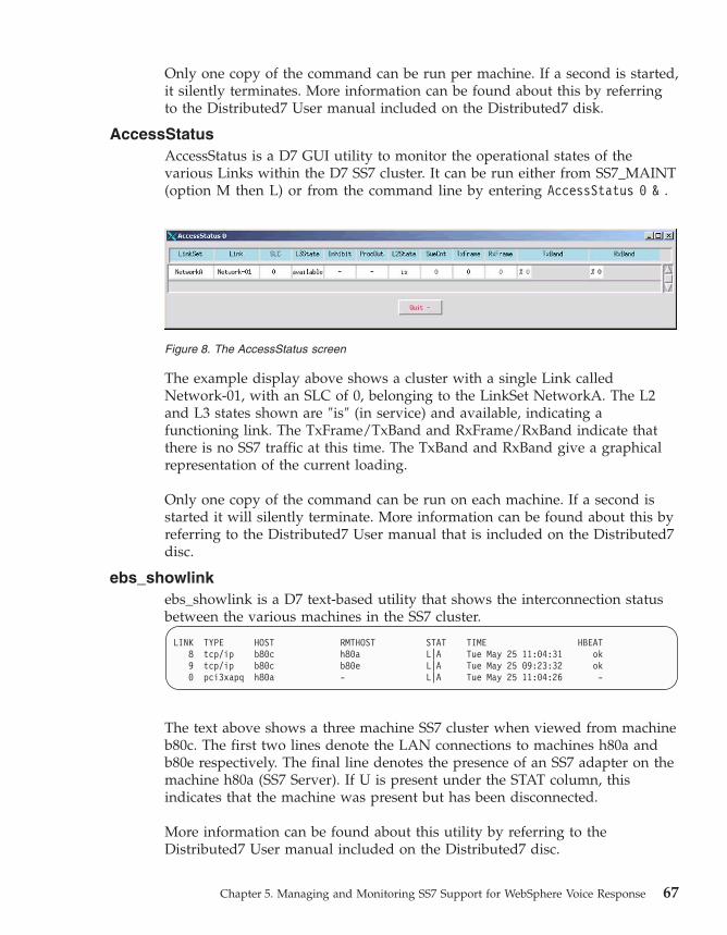
Only one copy of the command can be run per machine. If a second is started,
it silently terminates. More information can be found about this by referring
to the Distributed7 User manual included on the Distributed7 disk.
AccessStatus
AccessStatus is a D7 GUI utility to monitor the operational states of the
various Links within the D7 SS7 cluster. It can be run either from SS7_MAINT
(option M then L) or from the command line by entering AccessStatus 0 & .
The example display above shows a cluster with a single Link called
Network-01, with an SLC of 0, belonging to the LinkSet NetworkA. The L2
and L3 states shown are ″is″ (in service) and available, indicating a
functioning link. The TxFrame/TxBand and RxFrame/RxBand indicate that
there is no SS7 traffic at this time. The TxBand and RxBand give a graphical
representation of the current loading.
Only one copy of the command can be run on each machine. If a second is
started it will silently terminate. More information can be found about this by
referring to the Distributed7 User manual that is included on the Distributed7
disc.
ebs_showlink
ebs_showlink is a D7 text-based utility that shows the interconnection status
between the various machines in the SS7 cluster.
LINK TYPE HOST RMTHOST STAT TIME HBEAT
8 tcp/ip b80c h80a L|A Tue May 25 11:04:31 ok
9 tcp/ip b80c b80e L|A Tue May 25 09:23:32 ok
0 pci3xapq h80a - L|A Tue May 25 11:04:26 -
The text above shows a three machine SS7 cluster when viewed from machine
b80c. The first two lines denote the LAN connections to machines h80a and
b80e respectively. The final line denotes the presence of an SS7 adapter on the
machine h80a (SS7 Server). If U is present under the STAT column, this
indicates that the machine was present but has been disconnected.
More information can be found about this utility by referring to the
Distributed7 User manual included on the Distributed7 disc.
Figure 8. The AccessStatus screen
Chapter 5. Managing and Monitoring SS7 Support for WebSphere Voice Response 67

D7WVRErrorReport
D7WVRErrorReport is a second custom server of the D7 Enablement package.
Its sole purpose is to translate Alarm messages from the D7 package into
WebSphere Voice Response Alarm messages.
Translated messages can be collected from the local D7 package, or can be
received globally from any D7 package on the SS7 cluster. A number of D7
alarm messages have their own translation, with parameters translated into
more identifiable values (for example machine names) and descriptions to
highlight the condition and potential remedies.
Startup parameters
The startup parameters listed below can be applied to the custom server from
the top level WebSphere Voice Response GUI, after making the following
selections: Application —> Application —> SS7_D7 —> Custom servers —>
D7WVRErrorReport —> File —>Properties.
Remember to put only one parameter on each line.
Global Reporting
Use the -g parameter (together with -r) to register this D7 host as a
global collector of D7 alarms from other D7 hosts (SS7 Servers). See
“D7 Alarm Logging” on page 40.
Repetition Suppression
Use the –R <number> facility to reduce the number of repetitions of
the same Alarm message being passed to WebSphere Voice Response.
For example by entering –R 3 following the first occurrence of an
alarm causes the subsequent three identical alarms to be suppressed.
Use the –r parameter to disable this feature.
Reporting Level
Use the –d <1...3> parameter to define the reporting level. For an
Alarm message to be passed to WebSphere Voice Response it must
have a reporting level of greater than or equal to the parameter
supplied. For example –d 1 is the default and passes all alarm
messages.
Compile Translation File
Use –C to create a binary translation file based on the D7 package
error files. This option is used once on installation, to create a
translation file from D7 to WebSphere Voice Response, and is not
required during normal operation.
Configuration Files
D7WVRErrorReport has two configuration files:
68 SS7 User’s Guide

D7_ErrorList
The binary translation file created by the Compile Translation
file option above.
AlarmTranslation.cfg
This contains the mapping of D7 error codes to WebSphere
Voice Response alarm codes and associated reporting level.
For more information on this configuration refer to
Appendix C, “Configuration files,” on page 107.
Collecting event and trace information
Event information
As the SS7_D7 custom server processes messages between the WebSphere
Voice Response system and the SS7 stack, events are logged into shared
memory. This is a continuous activity and minimises the effect on the
performance of the function. This information can be read to screen and
recorded to files using the ss7view (see “ss7view –event” on page 62 for
details).
The events can be interpreted into message flows between the various
components with the ss7view –message option (see “ss7view –message” on
page 62 for details). The ss7view –event also has an option –R for copying the
shared memory direct to disk for offline processing. The primary purpose of
this event facility is to capture events prior to an error being report.
Reviewing the event enables diagnostics to be performed. The ss7view
–trigger (see “ss7view –trigger” on page 63) enables automatic capture of
event information direct to disk when selected errors message are detected.
The default operation of this function is defined in the logging and event file
configuration (see “Logging and event file” on page 109 for details).
Trace information
Trace information is a method of writing diagnostic information direct to disk
file. By default this function is disabled as it affects the performance of the
custom server when it is under load. The purpose of this trace facility is to
capture detailed information about messages and their parameters. This is
useful when first connecting to a new network or variant.
The ss7view –trace option controls whether this facility is enabled and what
elements are traced (see “ss7view -trace” on page 64 for details) .
Chapter 5. Managing and Monitoring SS7 Support for WebSphere Voice Response 69

70 SS7 User’s Guide

Chapter 6. Information elements passed to WebSphere
Voice Response
This section describes the WebSphere Voice Response tags that are supported
in the SS7 product.
Tag presentation and omissions
For all mandatory SS7 Information Elements that do not have tags supplied,
or part-completed tags, these fields are filled by the system defaults. Refer to
Appendix C, “Configuration files,” on page 107 for more information. The
following table shows a list of valid tags, describes the relationship between
call activities, and indicates when tags can be used. If any unsupported tags
are used, they are silently ignored.
Tag Name
Inbound call
setup
(SV542)
Outbound
call setup
(SV541)
Inbound call
termination
Outbound
call
termination
USR2USR U U U U
CLDN U U × ×
CLGP U U × ×
ORIGIN U U × ×
REDIRN U U × ×
REDINFO U U × ×
CHARGEN U U × ×
UTI U U × ×
USI U U × ×
CAUSE × × U U
NEWCLDN × × × U
PROTOCOL U × U ×
GENERICADDR U U U U
ISUPPARM U U U U
SERVICEACTIVATION × × U U
JINFO U U × ×
PINFO U U × ×
© Copyright IBM Corp. 2001, 2008 71

Country and network variants
The values specified in tags, and their attributes below, are a small subset of
the potential available values. Depending on the country or network variant
these values may change or different ones be preferred. In general this
package passes the values unchanged to and from the network, so if any
special values must be passed, this is possible without resorting to software
changes.
When changing values, both in tags and configuration files, it is important to
understand the effect and consequences of the change. For example, it may
not always be the best choice to turn off the Charging flag when answering all
calls
Tags types and descriptions
This section provides details of each tag and its attributes.
User-to-user information [USR2USR]
This is a sequence of free-format numbers that are not defined within the SS7
ITU/ANSI system. The maximum number in the sequence is 131, with each
number having the range of one byte unassigned (0 – 255). The number can
be specified either as decimal or hexadecimal—the latter must be proceeded
by 0x. Each number is separated by a comma, for example: 1, 3, 5, 7, 0x2, 0x4,
0x6 .
Called Number [CLDN]
This tag specifies the called number and associated attributes. The maximum
number of digits in the number is 24 (ITU/ANSI), and only digits from 0 – 9
are supported. To use this tag, leave the Phone Number and Format fields blank
in the MakeCall state table Action. The optional attributes are:
CLDN.NUMBER_TYPE
A numerical value defining the Nature of Address of the call, with the
following possible values:
1 Subscriber
3 National
4 International
5 Network Specific
CLDN.NUMBER_PLAN
a numerical value defining the Numbering Plan:
1 ISDN
72 SS7 User’s Guide

Calling Number [CLGP]
This tag specifies the calling number. The maximum number of digits in the
number is 24 (ITU/ANSI), and only digits from 0 – 9 are supported. The
optional attributes are:
CLGP.NUMBER_TYPE
A numerical value defining the Nature of Address of the call, with the
following possible values:
1 Subscriber
3 National
4 International
5 Network Specific
CLGP.NUMBER_PLAN
a numerical value defining the Numbering Plan:
1 ISDN
CLGP.SCREEN
Defines the screening indicator for the calling number, with the
following possible values:
0 User provided, not verified
1 User provided, verified and passed
2 User provided, verified and failed
3 Network provided
CLGP.PRESENT
Defines the address presentation indicator, with possible values as
follows:
0 Presentation allowed
1 Presentation restricted
2 Address not available
Original Number [ORIGIN]
This tag specifies the original number. It has the same specification and
optional attributes as Called Number, but has a tag name of ORIGIN.
Redirecting Number [REDIRN]
This tag specifies the redirecting number. It has the same specification and
optional attributes as Calling Number, but has a tag name of REDIRN.
Chapter 6. Information elements passed to WebSphere Voice Response 73

Redirecting Information [REDINFO]
This tag specifies the Redirecting Information associated with a call. There is
no tag information to be processed but the following attributes are processed:
REDINFO.IND
The redirecting method, with the following possible values:
0 No redirection
1 Call rerouted
2 Call rerouted, all redirection information presentation
restricted
3 Call diverted
4 Call diverted, all redirection information presentation
restricted
5 Call rerouted, redirection number presentation restricted
6 Call diversion, redirection number presentation restricted
REDINFO.ORIG
Indicates the original diverting reason, with the following possible
values:
0 Unknown or not available
1 User busy
2 No reply
3 Unconditional
REDINFO.COUNT
Indicates the number of redirections the call has undergone. The value
has a range of 1 – 5.
REDINFO.REASON
Reason for redirecting, with the following possible values:
0 Unknown or not available
1 User busy
2 No reply
3 Unconditional
4 Deflection during alerting
5 Deflection immediate response
6 Mobile subscriber not reachable.
74 SS7 User’s Guide

User Teleservices Information [UTI] (ITU Only)
This tag and its attributes define the User Teleservices Information IE. There
are three elements in the IE. The first will be present in the tag UTI and the
other two in attributes UTI.HLC_1 and UTI.HLC_2 respectively. These tags are
passed to WebSphere Voice Response as decimal, however an application can
present these numbers as decimal or hexadecimal (a two digit number
preceded by 0x).
User Services Information [USI]
This tag and its attributes define the User Services Information IE. There is no
value to the tag, but up to five attributes can be defined. Depending on the
attribute, one or a series of numbers can be specified. The number in this tag
is passed as decimal; however, the application can present these numbers as
decimal or hexadecimal. For series of numbers, each number is separated by a
comma. The attribute labels are as follows:
USI.OCTET_1
one value
USI.OCTET_2
up to three values
USI.OCTET_3
up to four values
USI.OCTET_4
one value
USI.OCTET_5
one value
Generic Address [GENERICADDR]
This tag specified the Generic Address number and associated attributes. The
optional attributes are:
GENERICADDR.ADDR_TYPE
Various values, refer to relevant documentation for ANSI – T1.113
3.20A or ITU – Q.763 326
GENERICADDR.NUMBER_TYPE
A numerical value defining the Nature of Address of the call, with the
following possible values:
1 Subscriber
3 National
4 International
5 Network Specific
Chapter 6. Information elements passed to WebSphere Voice Response 75

GENERICADDR.NUMBER_PLAN
a numerical value defining the Numbering Plan:
1 ISDN
GENERICADDR.SCREEN
this attribute defines the Screening indicator for the calling number:
0 User provided, not verified
1 User provided, verified and passed
2 User provided, verified and failed
3 Network provided.
GENERICADDR.PRESENT
This attribute defines the address presentation indicator:
0 Presentation allowed
1 Presentation restricted
2 Address not available
Service Activation Parameter [SERVICEACTIVATION]
This tag is available only during application call termination, and contains the
optional IE that is used to pass a switch-specific request, for example, transfer
this call on termination. The tag value is a numeric list (up to a maximum of
128 comma separated decimal or hexadecimal numbers) the decode of which
is specific to the local switch implementation of supplementary services (if
any). There are no attributes defined for this tag.
Jurisdiction Information Parameter [JINFO]
For an SS7 T1 inbound call application, the Jurisdiction Information is
presented as the value of Tag JINFO in system variable SV542.
For an outbound SS7 T1 call application, the Jurisdiction Information is set in
SV541 through the value of Tag JINFO.
The JINFO tag has a value of xxxxxx (digit string of up to six unpacked IA5
address digits) and has no tag attributes. The assumed format of this optional
IAM parameter received from the SS7 network is:
byte nameOFparam = 0xC4; /* JURISDICTION_INFO_PARM */
byte lenOFparam; /* (in bytes) */
byte DigitInfo[3]; /* Packed 2 digits per byte */
The DigitInfo array (packed) is mapped to the JINFO Tag value (unpacked).
76 SS7 User’s Guide
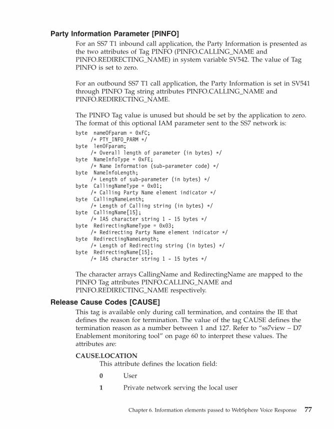
Party Information Parameter [PINFO]
For an SS7 T1 inbound call application, the Party Information is presented as
the two attributes of Tag PINFO (PINFO.CALLING_NAME and
PINFO.REDIRECTING_NAME) in system variable SV542. The value of Tag
PINFO is set to zero.
For an outbound SS7 T1 call application, the Party Information is set in SV541
through PINFO Tag string attributes PINFO.CALLING_NAME and
PINFO.REDIRECTING_NAME.
The PINFO Tag value is unused but should be set by the application to zero.
The format of this optional IAM parameter sent to the SS7 network is:
byte nameOFparam = 0xFC;
/* PTY_INFO_PARM */
byte lenOFparam;
/* Overall length of parameter (in bytes) */
byte NameInfoType = 0xFE;
/* Name Information (sub-parameter code) */
byte NameInfoLength;
/* Length of sub-parameter (in bytes) */
byte CallingNameType = 0x01;
/* Calling Party Name element indicator */
byte CallingNameLenth;
/* Length of Calling string (in bytes) */
byte CallingName[15];
/* IA5 character string 1 - 15 bytes */
byte RedirectingNameType = 0x03;
/* Redirecting Party Name element indicator */
byte RedirectingNameLength;
/* Length of Redirecting string (in bytes) */
byte RedirectingName[15];
/* IA5 character string 1 - 15 bytes */
The character arrays CallingName and RedirectingName are mapped to the
PINFO Tag attributes PINFO.CALLING_NAME and
PINFO.REDIRECTING_NAME respectively.
Release Cause Codes [CAUSE]
This tag is available only during call termination, and contains the IE that
defines the reason for termination. The value of the tag CAUSE defines the
termination reason as a number between 1 and 127. Refer to “ss7view – D7
Enablement monitoring tool” on page 60 to interpret these values. The
attributes are:
CAUSE.LOCATION
This attribute defines the location field:
0 User
1 Private network serving the local user
Chapter 6. Information elements passed to WebSphere Voice Response 77

2 Public network serving the local user
3 Transit network
4 Public network serving the remote user
5 Private network serving the remote user
7 International network
10 Network beyond internet working point
CAUSE.CODING_STD
This attribute defines the coding standard field, and reflects the
meaning of the Cause field:
0 ITU-T standardized coding
1 ISO/IEC standard
2 National standard
3 Standard specific to identified location
CAUSE.DIAGS
A series of numbers, separated by commas, in the range of 0 – 255, to
a maximum of 28 numbers
Protocol Type [PROTOCOL]
The PROTOCOL tag defines the signaling protocol—in this case it will always
be SS7, with the following attributes:
PROTOCOL.VARIANT
This has the same value as selected in the Environment screen of
SS7itty
PROTOCOL.ISUP
This is the ISUP variant.
Note: This tag is generated by D7 Enablement only and has no effect when
passed in as a tag from WebSphere Voice Response.
Switching SS7 Default values [ISUPPARM]
The configuration file ISUPParm.cfg contains the SS7 default values. However
these values can be cloned and modified into different ″named″ sets. The tag
ISUPPARM allows these different parameter sets to be used with the tag value
naming the cloned set. This facility is useful if :
v Values need to be changed on a call by call basis but the tags for the value
are not available.
v A number of tags are being used on a regular basis to justify creating their
own set.
78 SS7 User’s Guide

For details in creating these cloned sets refer to Appendix C, “Configuration
files,” on page 107.
Special case tags
The following tag is a special case and its availability and operation may be
dependant on the local switch or network.
Release with new Called Party Number[NEWCLDN]
The NEWCLDN tag is specifically formed to decode a replacement Called
Party Number into the Diagnostic field of a Release message. The format of
the Tag and attributes is the same as Called Number above. Since this tag
affects the Cause and Diagnostics fields of the Release message it must
following a CAUSE tag.
System variables
For backwards compatibility the following system variables are supported in
SS7. Note that these variables are available only to the State table applications,
and tag values have precedence over System Variables.
The table below shows the list of system variables and the equivalent tag
information.
Notes:
1. For SV187 and SV188, these are the default assignments and can be
reassigned via the service.cfg configuration file (see“Service configurable
options” on page 111 for details).
2. WebSphere Voice Response truncates to 20 digits numbers that are stored
in these system variables (if a tag supports more than 20 digits).
System variable Associated tags
SV185 : Called Number CLDN
SV186 : Calling Number CLGP
SV187 : User 1 ORIGIN
SV188 : User 2 REDIRN
Chapter 6. Information elements passed to WebSphere Voice Response 79

80 SS7 User’s Guide

Chapter 7. Problem determination
This section aims to identify any problems in SS7 Support for WebSphere
Voice Response, and suggests possible fixes to them.
Stage 1: Is the SS7 Server working?
This test investigates whether the D7 package is present on this machine and
checks its current state of operation, by using the following instructions:
1. Log onto the SS7 Server machine as dtuser
2. Enter the SS7_MAINT command
3. From the top level menu, enter F (Fault Finding)
4. On the submenu, enter 2 (D7 Process Check)
A screen similar to that below is displayed:
***************************
*** D7 Process checking ***
***************************
PID STAT MODE HOST MUX OBJECT
9852 ok LX|A b80ss7b spm/0 daemon [name=apmd]
7358 ok LX|A b80ss7b spm/2 daemon [name=mlogd]
8716 ok LX|A b80ss7b spm/3 daemon [name=spmd]
11428 ok LX|A b80ss7b spm/4 daemon [name=netd]
27248 ok LX|A b80ss7b spm/5 daemon [name=alarmd]
27248 ok L|A b80ss7b spm/6 nmdobj [name=AlarmExt]
23362 ok LX|A b80ss7b spm/7 daemon [name=dsmd]
23622 ok LX|A b80ss7b spm/8 daemon [name=dkmd]
24032 ok LX|A+ b80ss7b upm/0/0 daemon [name=upmd0]
27488 ok LX|A b80ss7b upm/0/3 ss7obj [sp=0 up=5]
27154 ok N|A b80h spm/11 nmdobj [name=b80h]
4182 ok L|A b80ss7b spm/16 nmdobj [name=ebs_ps]
************
*** SUCCESS: D7 system configured for SS7 Server
Based on the message at the bottom of your screen, go to the corresponding
section as defined in this table:
Message Action
SUCCESS : D7 system configured for SS7 Server Go to stage 1c
SUCCESS : D7 system configured for WVR operation Go to stage 1a
FAILED : D7 system is not running Go to stage 1b
FAILED : MTP-3(upmd) is not running Go to stage 1d
FAILED : ISUP(isupd) is not running. Go to stage 1d
© Copyright IBM Corp. 2001, 2008 81

Stage 1a: Machine is not a Server
This machine appears to be configured for WebSphere Voice Response client
use. Try the following steps:
1. Use option D from the SS7_MAINT top-level menu to stop and then
restart the D7 package.
2. Then repeat the machine configuration; enter S followed by S again.
Stage 1b: D7 package is not running
As it suggests, it appears that the D7 package is not running. Try using option
D in SS7_MAINT to start the D7 package. Using the M option may offer
useful information as to why it does not start.
Stage 1c: D7 system configured for SS7 Server
This is the expected outcome, so continue to Stage 2. If the machine has been
configured as a combined server/client, this is also the correct outcome.
Stage 1d: MTP-3(upmd) / ISUP(isupd) is not running
The machine is configured for SS7 Server operation, however one or more of
the higher layers of the SS7 Stack do not appear to be working. Try the
following steps:
1. Use option D of SS7_MAINT to stop and then restart the D7 package.
2. Use SS7_MAINT to stop and then restart the D7 package with the M
option, and monitor any error messages being generated by the D7
package. Cross-reference these problems with those listed in “Obscure
Problems” on page 97.
Stage 2: Which other machines are present?
After completing Stage 1, you should have an SS7 Server machine with a D7
package running. The next stage is to investigate which other machines are
present in the SS7 Cluster.
If the SS7 cluster is a single machine then skip this stage and go to Stage 3
Otherwise use the following steps to investigate which other machines are
present, and their state of health:
1. Log onto the SS7 Server machine as dtuser.
2. Enter the SS7_MAINT command.
3. From the top level menu, enter F (Fault Finding).
4. From the submenu enter 1 (D7 Network Check).
A screen is displayed as below:
82 SS7 User’s Guide

***************************
*** D7 Network checking ***
***************************
LINK TYPE HOST RMTHOST STAT TIME HBEAT
8 tcp/ip Mercury Venus L|A Mon May 17 13:49:24 ok
9 tcp/ip Mercury Mars U Tue May 18 10:52:16 -
0 pci3xapq Venus - L|A Mon May 17 13:49:17 -
Select an option :
The output above is from a machine named Mercury, and indicates the
following:
The first line shows a good connection between machines Mercury and
Venus.
The second line shows a failed connection between machines Mercury and
Mars, but that it was once a valid connection.
The third line shows an SS7 Adapter has been activated on machine Venus.
By matching the data displayed on your screen with the symptoms listed
below, go to the corresponding section liste in the Action column:
Symptom Action
A machine is missing from the list Go to stage 2a
A listed machine under RMTHOST has a U under the
STAT column
Go to stage 2b
An SS7 adapter card is missing from the list, but the
machine holding the adapter is present in the list
Go to stage 2c
If all expected machines and SS7 adapters are present Go to stage 2d
Stage 2a : A machine is missing from the cluster
If the machine is configured as an SS7 Server (or Combined) then repeat Stage
1 for that machine. Otherwise proceed to stage 3, assuming it is configured as
a WebSphere Voice Response client.
Stage 2b: The named machine in RMTHOST has been part of the SS7
cluster but has since failed
Go to Stage 4
Stage 2c: A machine containing an SS7 adapter card is present in the SS7
cluster, but is not activated
Go to Stage 6
Stage 2d: The machines within the SS7 cluster appear to be in order
Go to Stage 5
Chapter 7. Problem determination 83

Stage 3: Is D7 working on a WebSphere Voice Response Client?
This test attempts to identify why the D7 package is not working on a
machine that is configured for WebSphere Voice Response Client operation.
Perform the following steps:
1. Log onto the SS7 Server machine as dtuser
2. Enter the SS7_MAINT command
3. From the top level menu, enter F (Fault Finding)
4. On the submenu, enter 2 (D7 Process Check)
A screen similar to the one below is displayed:
***************************
*** D7 Process checking ***
***************************
PID STAT MODE HOST MUX OBJECT
124806 ok LX|A b80e spm/0 daemon [name=apmd]
124234 ok LX|A b80e spm/2 daemon [name=mlogd]
43552 ok LX|A b80e spm/3 daemon [name=spmd]
36588 ok LX|A b80e spm/4 daemon [name=netd]
147110 ok LX|A b80e spm/5 daemon [name=alarmd]
147110 ok L|A b80e spm/6 nmdobj [name=AlarmExt]
108324 ok LX|A b80e spm/7 daemon [name=dsmd]
153932 ok LX|A b80e spm/8 daemon [name=dkmd]
43802 ok L|A b80e spm/10 nmdobj [name=ebs_ps]
************
*** SUCCESS : D7 system configured for WVR operation
************
Based on the message at the bottom of your screen, go to the corresponding
section as defined in this table:
Message Action
SUCCESS : D7 system configured for SS7 Server . Go to stage 3a
SUCCESS : D7 system configured for WVR operation Go to stage 3b
FAILED : D7 system is not running Go to stage 3c
FAILED : MTP-3(upmd) is not running Go to stage 3a
FAILED : ISUP(isupd) is not running. Go to stage 3a
Stage 3a: The machine is not a WebSphere Voice Response client
This machine appears to be configured for SS7 Server use. Try the following
steps:
1. Use option D of SS7_MAINT to stop and then restart the D7 package
2. Repeat the machine configuration with SS7_MAINT; use option S followed
by option W.
84 SS7 User’s Guide

Stage 3b: The machine is correctly running as a WebSphere Voice
Response client.
If this machine was not present in a Stage 2 test, proceed to Stage 5
Stage 3c: D7 package is not running
It appears that the D7 package is not running. Try using option D of
SS7_MAINT to start the D7 package. Using the M option may offer useful
information as to why it does not start.
Stage 4: Machine has been present in the SS7 cluster but is not now?
Try the following step on the machine that has disappeared from the SS7
cluster.
1. Log onto the SS7 Server machine as dtuser
2. Enter the SS7_MAINT command
3. From the top level menu, enter F (Fault Finding)
4. On the submenu, enter 2 (D7 Process Check)
A screen similar to the one below is displayed:
***************************
*** D7 Process checking ***
***************************
PID STAT MODE HOST MUX OBJECT
124806 ok LX|A b80e spm/0 daemon [name=apmd]
124234 ok LX|A b80e spm/2 daemon [name=mlogd]
43552 ok LX|A b80e spm/3 daemon [name=spmd]
36588 ok LX|A b80e spm/4 daemon [name=netd]
147110 ok LX|A b80e spm/5 daemon [name=alarmd]
147110 ok L|A b80e spm/6 nmdobj [name=AlarmExt]
108324 ok LX|A b80e spm/7 daemon [name=dsmd]
153932 ok LX|A b80e spm/8 daemon [name=dkmd]
43802 ok L|A b80e spm/10 nmdobj [name=ebs_ps]
************
*** SUCCESS : D7 system configured for WVR operation
************
Based on the message at the bottom of your screen, go to the corresponding
section as defined in this table:
Message Action
SUCCESS : D7 system configured for SS7 Server . Go to stage 4a
SUCCESS : D7 system configured for WVR operation Go to stage 4b
FAILED : D7 system is not running Go to stage 4c
FAILED : MTP-3(upmd) is not running Go to stage 4d
FAILED : ISUP(isupd) is not running. Go to stage 4d
Chapter 7. Problem determination 85

Stage 4a: The machine has been configured for SS7 Server
The report suggests that the machine has been configured for SS7 Server (or
Combined). If this is correct, proceed to Stage 5. Otherwise repeat stage 3 with
this machine.
Stage 4b: The machine has been configured as a WebSphere Voice
Response client
The report suggests that the machine has been configured for WebSphere
Voice Response client. If this is correct, proceed to Stage 5. Otherwise repeat
stage 1 with this machine.
Stage 4c: D7 package is not running
It appears that the D7 package is not running. Try using option D of
SS7_MAINT to start the D7 package. Using the M option may offer useful
information as to why it does not start.
Stage 4d: There is a problem starting this machine as an SS7 Server
There appears to a problem in starting this machine as an SS7 Server or
combined client/server. If this is the correct configuration, then return to
Stage 1. Otherwise return to Stage 3.
Stage 5: Two machines are not communicating
This stage investigates why two machines are not communicating with each
other. Perform the following tests on both machines.
1. Log onto the SS7 Server machine as dtuser
2. Enter the SS7_MAINT command
3. From the top level menu, enter F (Fault Finding)
4. From the submenu, enter 1 (D7 Network Check)
An example of the output is shown in “Stage 2: Which other machines are
present?” on page 82.
By comparing the data displayed on your screen with the symptoms listed
below, go to the corresponding section listed in the Action column:
Symptom Action
Both entries have a U in the STAT column in both
outputs
Go to stage 5a
One output shows L|A and the other shows U in the
STAT column
Go to stage 5b
Both entries show L|A in the STAT column Go to stage 5c
One or both of the machines is missing from the
other’s output
Go to stage 5d
86 SS7 User’s Guide

Stage 5a: There is no communication between the machines.
Try the following steps
1. Verify the LAN connection between the two machines and its quality.
2. Review the SS7itty configuration to ensure that the specified Primary LAN
address for each machine is correct, that is, they match the values returned
when you enter hostname –s.
3. Restart the D7 package on both machines.
Stage 5b: There has been a connection between the machines at one
time.
Try the following actions:
1. Verify the quality of the LAN connections and that communication
between the two machines is possible.
2. Restart the D7 package on both machines and then repeat this stage.
Stage 5c: There is a good connection between the two machines
In this case the problem has been resolved. It may be that the problem in
intermittent and this stage should be repeated.
Stage 5d: There is a configuration problem in defining the machines
within the SS7 Cluster
Try the following steps:
1. Review the SS7itty configuration to ensure that all machines have been
declared, and have correct Primary LAN addresses.
2. Restart the D7 packages for the two machines.
3. Reapply the Host MML configuration – use options C and H from top
level menu of SS7_MAINT. Review the log file for errors, then restart the
D7 package on the two machines.
4. Refer to the subsection on flush configuration in Chapter 8, “Migration,”
on page 99.
Stage 6: SS7 Adapter checks
This stage investigates the presence of SS7 Adapters. Perform the following
tests:
1. Log onto the SS7 Server machine as dtuser
2. Enter the SS7_MAINT command
3. From the top level menu, enter F (Fault Finding)
4. On the submenu, enter 1 (D7 Network Check)
An example of the output is shown in “Stage 2: Which other machines are
present?” on page 82.
Chapter 7. Problem determination 87
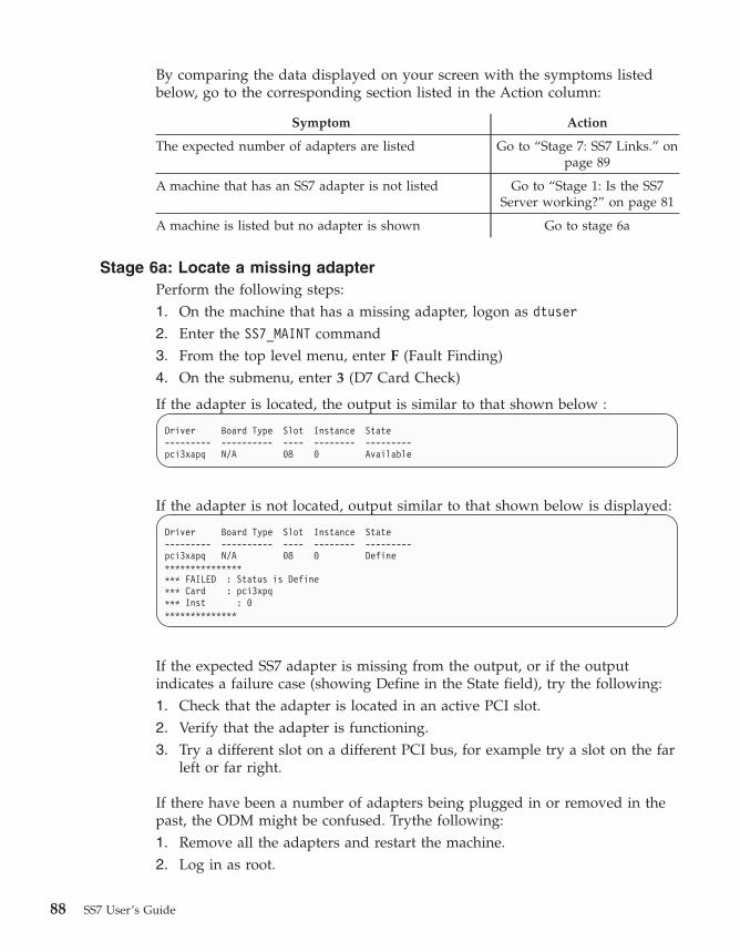
By comparing the data displayed on your screen with the symptoms listed
below, go to the corresponding section listed in the Action column:
Symptom Action
The expected number of adapters are listed Go to “Stage 7: SS7 Links.” on
page 89
A machine that has an SS7 adapter is not listed Go to “Stage 1: Is the SS7
Server working?” on page 81
A machine is listed but no adapter is shown Go to stage 6a
Stage 6a: Locate a missing adapter
Perform the following steps:
1. On the machine that has a missing adapter, logon as dtuser
2. Enter the SS7_MAINT command
3. From the top level menu, enter F (Fault Finding)
4. On the submenu, enter 3 (D7 Card Check)
If the adapter is located, the output is similar to that shown below :
Driver Board Type Slot Instance State
--------- ---------- ---- -------- ---------
pci3xapq N/A 08 0 Available
If the adapter is not located, output similar to that shown below is displayed:
Driver Board Type Slot Instance State
--------- ---------- ---- -------- ---------
pci3xapq N/A 08 0 Define
***************
*** FAILED : Status is Define
*** Card : pci3xpq
*** Inst : 0
**************
If the expected SS7 adapter is missing from the output, or if the output
indicates a failure case (showing Define in the State field), try the following:
1. Check that the adapter is located in an active PCI slot.
2. Verify that the adapter is functioning.
3. Try a different slot on a different PCI bus, for example try a slot on the far
left or far right.
If there have been a number of adapters being plugged in or removed in the
past, the ODM might be confused. Trythe following:
1. Remove all the adapters and restart the machine.
2. Log in as root.
88 SS7 User’s Guide

3. Run cfgmgr
Repeat stage 6a; if cards are still being shown as missing, seek help in
correcting the ODM database.
Stage 7: SS7 Links.
Reaching this stage indicates that the D7 package is functioning correctly on
all machines in the SS7 cluster, and that this machine has the correct
configuration.
This stage checks if all the SS7 links are functional. Perform the following
steps:
1. Logon to one of the SS7 Servers as dtuser
2. Enter the SS7_MAINT command
3. From the top level menu, enter M (D7 Maintenance Programs)
4. On the submenu, enter L (Link Status)
The link monitoring program (AccessStatus) is started, and a screen similar to
that below appears:
There should be one entry displayed for each Link that was configured in
SS7itty. If one is missing, return to SS7itty and review the Link configuration.
There might also be additional information present in the log file
/usr/lpp/dirTalk/db/current_dir/ca/SS7_D7_cfg/log/mml.log. Once you
have corrected the link information, perform the following steps:
1. Reapply the SS7 configure in SS7_MAINT, by selecting options C, followed
by S alongside the name of the machine on which the Link is configured
to be present. Review the error log, but ignore any errors that suggest
duplication.
2. Otherwise perform the reconfiguration as outlined in Chapter 8,
“Migration,” on page 99.
Figure 9. The link monitoring program screen
Chapter 7. Problem determination 89

Based on the status of the links in the link monitoring display, select from the
following:
Status Action
If an entry is not showing ″is″ under the column
L2State
Go to stage 8a
If an entry does not show ″available″ under L3State,
but does show ″is″ under L2State
Go to stage 8b
If all entries show ″available″ and ″is″ Go to “Stage 9: Is the
Enablement package
working?”
Stage 8a: The physical connection for this Link is faulty
Try the following procedure:
1. Check that the correct port on the adapter has been cabled, and that the
cable is connected to a valid port at the remote end. If a T1/E1 analyser is
present, this will help to prove it.
2. Examine the alarm files in /usr/opt/D7/access/RUN/alarmlog. Entries
that are similar to the following would point to a problem with the
physical connection:
Tue May 11 11:11:18 2004
ALARM $870101 HOST: Venus SP: 0 LVL: Minor
MTP-L2: T2 expired [lset=1 link=0]
Tue May 11 11:11:18 2004
ALARM $87010a HOST: Venus SP: 0 LVL: Minor
MTP-L2: Alignment not possible [lset=1 link=0]
3. Verify that the correct timeslot has been selected when using SS7itty.
Stage 8b: Incorrect Point Code value
This suggests that the cabling is functioning correctly, but what is connected
at the remote end does not match the expected Point Code. Verify that the
DPC value configured in SS7itty under Link Sets matches the Point Code of
the far end.
Stage 9: Is the Enablement package working?
Repeat this stage for each WebSphere Voice Response client in the SS7 cluster:
1. Log onto the WebSphere Voice Response client as dtuser.
2. From the top level of the WebSphere Voice Response GUI select Operation
—> Custom Server Manager. From the list, check that the following
custom servers are present:
v SS7_D7
v D7WVRErrorReport
90 SS7 User’s Guide
Status Action
If either is missing Go to stage 9a
If both are present but either is not running Go to stage 9b
If neither of the above conditions apply Go to stage 9c
Stage 9a: The custom servers have not been imported.
Try the following solution:
1. Logon as dtuser.
2. Enter the SS7_MAINT command.
3. From the top level menu, enter S (SS7 Server/WebSphere Voice Response
Client).
4. From the submenu, enter W (Configure this Machine). This performs the
WebSphere Voice Response client configuration process, including the
import of the custom server at step 5. Watch for any errors being reported.
Stage 9b: A custom server is not running
While monitoring the WebSphere Voice Response system monitor screen, start
the custom server(s). A white information alarm will report that the SS7_D7
has started. Select from the following outcomes:
Outcome Action
No further alarms are reported Go to “Stage 10” on page 92.
Alarm 30038 is reported Go to stage 9c
Alarm 30001 is reported Go to stage 9d
A number of alarms 30008 are reported Go to Stage 9e
Stage 9c: One or more configuration files cannot be located
Try the following to correct this situation:
1. Logon as dtuser.
2. Enter the SS7_MAINT command.
3. From the top level menu, enter S (SS7 Server/WebSphere Voice Response
Client).
4. From the submenu, enter W (Configure this Machine). This performs the
WebSphere Voice Response client configuration, including copying the
configuration file at step 7. Watch for any errors being reported.
Stage 9d
The 30001 alarm indicates that the SS7_D7 custom server has been rejected
when attempting to bind and activate the ISUP interface. Try the following:
Chapter 7. Problem determination 91

1. If the SS7 Server has been redefined recently, check that this WebSphere
Voice Response client has received an updated copy of its configuration
files. Refer to“Installation on a WebSphere Voice Response client” on page
28.
2. If subtext suggests that the a GRPID does not exist, check that the
WebSphere Voice Response pack configuration matches the values that
were configured in SS7itty.
Stage 9e
Clear the alarms from the system monitor and if they do not reoccur, go to
Stage 10. Otherwise, this might suggest that there is a compatibility problem
between the SS7 variants, in which case seek further advice.
Stage 10
At this stage the following have been tested and proved to be working:
v All D7 packages are installed and functioning correctly
v All SS7 links are activated and working
v All custom servers relating to D7 Enablement are installed and working
The circuit is now brought into service and verified. Perform the following on
all WebSphere Voice Response clients:
1. Logon to the system as dtuser
2. Enter SS7_MAINT
3. Select the option M from the top level menu, and then M again. The
following screen is displayed:
92 SS7 User’s Guide
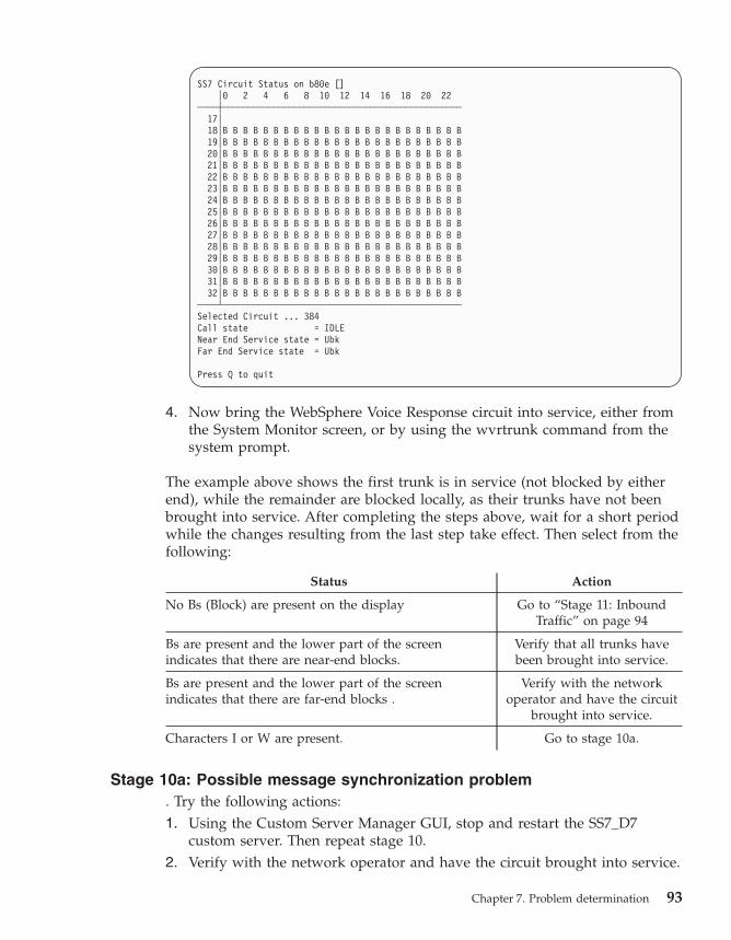
SS7 Circuit Status on b80e []
│0 2 4 6 8 10 12 14 16 18 20 22
────┼───────────────────────────────────────────────
17│
18│B B B B B B B B B B B B B B B B B B B B B B B B
19│B B B B B B B B B B B B B B B B B B B B B B B B
20│B B B B B B B B B B B B B B B B B B B B B B B B
21│B B B B B B B B B B B B B B B B B B B B B B B B
22│B B B B B B B B B B B B B B B B B B B B B B B B
23│B B B B B B B B B B B B B B B B B B B B B B B B
24│B B B B B B B B B B B B B B B B B B B B B B B B
25│B B B B B B B B B B B B B B B B B B B B B B B B
26│B B B B B B B B B B B B B B B B B B B B B B B B
27│B B B B B B B B B B B B B B B B B B B B B B B B
28│B B B B B B B B B B B B B B B B B B B B B B B B
29│B B B B B B B B B B B B B B B B B B B B B B B B
30│B B B B B B B B B B B B B B B B B B B B B B B B
31│B B B B B B B B B B B B B B B B B B B B B B B B
32│B B B B B B B B B B B B B B B B B B B B B B B B
────┴───────────────────────────────────────────────
Selected Circuit ... 384
Call state = IDLE
Near End Service state = Ubk
Far End Service state = Ubk
Press Q to quit
4. Now bring the WebSphere Voice Response circuit into service, either from
the System Monitor screen, or by using the wvrtrunk command from the
system prompt.
The example above shows the first trunk is in service (not blocked by either
end), while the remainder are blocked locally, as their trunks have not been
brought into service. After completing the steps above, wait for a short period
while the changes resulting from the last step take effect. Then select from the
following:
Status Action
No Bs (Block) are present on the display Go to “Stage 11: Inbound
Traffic” on page 94
Bs are present and the lower part of the screen
indicates that there are near-end blocks.
Verify that all trunks have
been brought into service.
Bs are present and the lower part of the screen
indicates that there are far-end blocks .
Verify with the network
operator and have the circuit
brought into service.
Characters I or W are present. Go to stage 10a.
Stage 10a: Possible message synchronization problem
. Try the following actions:
1. Using the Custom Server Manager GUI, stop and restart the SS7_D7
custom server. Then repeat stage 10.
2. Verify with the network operator and have the circuit brought into service.
Chapter 7. Problem determination 93

Stage 11: Inbound Traffic
This suggests that all the circuits are now working and ready for call traffic.
To test, make an inbound call to a valid number on the WebSphere Voice
Response Client, then select from the following outcomes:
Outcome Action
After dialling, silence is heard Go to stage 11a
After dialling, a busy tone is heard, or a similar verbal
report
Go to stage 11c
You successfully connect to WebSphere Voice
Response, and receive the selected service
Go to “Stage 12: Testing
outbound calls” on page 96
Stage 11a: Verify that the call is coming into a WebSphere Voice
Response client
To simplify this task, select one WebSphere Voice Response client, which
should be configured to receive inbound call for the dialled service. Take the
remaining WebSphere Voice Response systems out of service. Now perform
the following steps:
1. Log into the selected system as dtuser.
2. Enter ss7view –message.
3. Make an inbound call to the selected service If the inbound call is
successfully answered, the following output is displayed:
13:29:38.264:0000: IAM/ISUP_SETUP[1234] ---------->>
13:29:38.265:0000: SL_CALL_SETUP_IND ---------->>
13:29:38.265:0000: <<---------- ACM/ISUP_OGC_SELECTED
13:29:38.265:0000: <<---------- ACM/ISUP_ALERT
13:29:38.268:0000: <<---------- SL_CALL_ANSWER_REQ
13:29:38.268:0000: SL_CALL_ANSWER_CNF [SL_REPLY_SUCCESS] ------->>
13:29:38.269:0000: <<---------- ANM/ISUP_SETUP
.......
13:29:41.846:0000: <<---------- SL_CALL_TERMINATE_REQ
13:29:41.846:0000: <<---------- REL/ISUP_RELEASE[Cause:CSV_NORMALCALLCLR]
13:29:41.861:0000: RLC/ISUP_RELEASE ---------->>
13:29:41.862:0000: SL_CALL_TERMINATE_CNF [SL_REPLY_SUCCESS] ---->>
94 SS7 User’s Guide

Now select from the following:
Status Action
There was no output Go to stage 11b
The IAM/ISUP_SETUP was shown but no
SL_CALL_SETUP_IND
Go to stage 11c
The SL_CALL_SETUP_IND was shown but no
SL_CALL_ANSWER_REQ
Go to stage 11d
The sequence as shown in the screen above (down to
the line ANM/ISUP_SETUP) was displayed
Go to stage 11e
Stage 11b: An inbound call is not being received by the SS7 cluster
Verify with the network operator that the configuration is correct and has
been enabled.
Stage 11c: SS7_D7 has rejected the call request, possibility with invalid
parameters.
This condition should be supported by alarms appearing in the WebSphere
Voice Response System Monitor. If further help is required collect event and
trace data (the test will need to be repeated). For more information see
“Collecting event and trace information” on page 69. Pass this information to
IBM support for assistance.
Stage 11d: Possible problem in the call-answering mechanism of
WebSphere Voice Response
Refer to the relevant documentation for the application language used, to
verify that it has been correctly assigned.
Stage 11e: The inbound call is connected and the application is running.
Try the following steps:
1. Ensure that the application is delivering voice information.
2. Ensure the voice bearer cables for connections to the associated DTXA or
DTTA cards are present, and in the correct order (voice could be
transmitted down the wrong cable).
Chapter 7. Problem determination 95

Stage 12: Testing outbound calls
Arrange for an application to generate an outbound call, and monitor the SS7
message as before by entering ss7view –message –t. Perform the outbound
call. If it works, the display will look similar to below:
13:49:03.918:0383: <<---------- SL_CALL_SETUP_REQ
13:49:03.924:0383: <<---------- IAM/ISUP_SETUP[624185]
13:49:03.947:0383: ACM/ISUP_PROCEED ---------->>
.......
13:49:05.879:0383: ANM/ISUP_SETUP ---------->>
13:49:05.879:0383: SL_CALL_SETUP_CNF [SL_REPLY_SUCCESS] ---------->>
.......
13:49:10.110:0383: <<---------- SL_CALL_TERMINATE_REQ
13:49:10.110:0383: <<---------- REL/ISUP_RELEASE[Cause:CSV_NORMALCALLCLR]
13:49:10.127:0383: RLC/ISUP_RELEASE ---------->>
13:49:10.127:0383: SL_CALL_TERMINATE_CNF [SL_REPLY_SUCCESS] ---------->>
If not, select from the following:
Status Action
No message are displayed Go to stage 12a
The first line containing SL_CALL_SETUP_REQ is
present but the second is not, or is not the same as
containing IAM/ISUP_SETUP
Go to stage 12b
The message format matches, but the destination was
not contacted (did not ring)
Verify that the outbound
called number is correct for
the device you are trying to
contact.
Stage 12a: Check the returned value from the application’s Makecall
instruction
You might find the following problems:
v The MakeCall request is rejected due to bad numbers or parameters. Check
all the parameters. Try to simplify the tags or parameters.
v No Outbound lines available. Check that the relevant circuits (both local
and remote) are in service. The remote end can be checked using the
ss7view –circuit command.
Stage 12b: The network is rejecting the call
Look at the output from ss7view –message for a REL/ISUP RELEASE going
from the network to WebSphere Voice Response (left to right). It contains a
cause code in square brackets—this is the reason the call is being rejected. Use
the ss7view –cause <name> to translate the cause code. For example ss7view
–cause CSV_NORMALCALLCLR returns ″Normal call, clearance″.
96 SS7 User’s Guide

Redundancy – WebSphere Voice Response client failure.
When a WebSphere Voice Response client fails or is taken offline, the
associated SS7 Server that is managing its circuits passes responsibility and
control to another WebSphere Voice Response client. As a WebSphere Voice
Response client that is taking over the circuits of another client cannot
perform call control on these circuits (the voice bearers are not physically
connected to it), it can only take the circuits out of service in a controlled
manner, and thereby ensure no further calls are taken by these circuits.
When the original WebSphere Voice Response client comes back online, it
takes back the reassigned circuits from the other WebSphere Voice Response
clients. The WebSphere Voice Response System Monitor reports alarm
messages when it is given control of another client’s circuits, and again when
it releases these circuits.
The ss7view –circuit command shows this changeover. It replaces with A the –
character for the CICs of other WebSphere Voice Response systems, when this
client is requested to take over.
The effects of call overload
Whenever a new application is planned for your configuration, you should
carefully consider the call volume or call rate. The planning section earlier in
this document describes how to calculate the Link requirements. However, if
these are not reviewed when new applications are added to the WebSphere
Voice Response system, you might find that the original calculation does not
meet the new requirements.
The effect of overloading Links can vary from application to application but
possible problems might include:
v Calls do not connect, or are slow to connect even when there are many free
circuits.
v The HMCG messages from the D7 package occur frequently.
v Quiescing circuits does not seem to work.
v Large numbers of unrelated error messages are reported.
Obscure Problems
HMCG Alarm Message
The HMCG Alarm messages are generated by the D7 package (SS7 Stack)
when there are too many messages buffered for transmission. These messages
indicate that new messages will be discarded until the ″low-water mark″ in
the message buffer has been reached.
Chapter 7. Problem determination 97
This message typically occurs when circuits are taken in and out of service,
possibly when they are under heavy call load. If large numbers of these
messages are occurring, revisit Chapter 2, “Planning,” on page 13. However if
the problem occurs in small bursts around circuits being taken in and out of
service, it is possible to change the ″high-water mark″ to a higher value.
LAN Configuration problems
If you suspect that the SS7 cluster is having LAN problems, check whether
SS7 Machines are reporting other machines appearing, and then disappearing
from the LAN.
Most LAN configurations are set for auto-negotiation, which typically
configures at 100 MB per second, full duplex. However some machine types
(for example H80), when set for auto-negotiation, select half duplex which
causes problems on the LAN. You can check this by entering the AIX
command entstat –d <LAN device>, where <LAN device> is the interface
being used, for example en0.
Look towards the bottom of the data displayed for the lines:
Media Speed Selected: Auto negotiation
Media Speed Running: 100 Mbps Full Duplex
If the ″Speed Running″ is not set to Full Duplex, contact your AIX expert to
correct the status.
Unexpected primitive
Occasionally, the D7 package may report unexpected primitives. These are
warnings and are not necessarily errors. A primitive is likely to be
″unexpected″ because it is out of sequence. This typically occurs when both
parties release at the same moment in time.
However if this occurs in more than 1 in 100 calls it may suggest there is a
problem in the ISUP variant being used. In this case you should contact your
IBM representative for more information.
Machine locks up in dual LAN configuration
If one or more machines in an SS7 Cluster no longer respond to LAN-based
commands or other operations on the stream package, it may be caused by D7
having become confused. In this case, you should review the dual LAN
configuration. An imbalance in any machine in the configuration may cause
confusion within D7. Typical failures include:
v Incorrect routing
v Mixed routing
v Inability to resolve LAN addresses
98 SS7 User’s Guide

Chapter 8. Migration
Upgrading from an existing Distributed7 or D7 Enablement package to a new
version is straightforward. Before starting, always ensure that you:
v Read any README file in the upgrade software package.
v Have put a copy of the Distributed7 licence in a safe place.
SS7 Server migration
Remove the existing packages (D7 and D7 Enablement). The D7 Enablement
configuration directories remain on your machine and are not overwritten, so
the SS7_MAINT operation is not required, other than to restart the packages.
Install the upgrade packages as outlined in Chapter 3, “Installing SS7 Support
for WebSphere Voice Response,” on page 21 earlier in this document.
WebSphere Voice Response client migration
Remove the existing packages (D7 and D7 Enablement). If you are updating
the WebSphere Voice Response base product, you should make a backup of
the following directories:
/usr/lpp/dirTalk/db/current_dir/ca/SS7_D7_cfg/*
/usr/lpp/dirTalk/db/current_dir/ca/D7WVRErrorReport/*
After completing the upgrade of the WebSphere Voice Response base product,
check that the above directories are still present. If they are not, recover them
from the backup. Install the upgrade packages as outlined in Chapter 3,
“Installing SS7 Support for WebSphere Voice Response,” on page 21.
Adding additional machines to the SS7 Cluster
This section describes the operation of adding additional machines to your
SS7 cluster. If there are any changes or removals from the configuration, read
“Changes or Removals from SS7 Cluster” on page 100 first.
v Review Chapter 2, “Planning,” on page 13 to ensure that there are sufficient
Links to carry the new traffic to your machines.
v Review your license needs with your IBM representative. New licenses may
need to be installed on existing machines as well as on the new machine.
v Update the entries in SS7itty to include the new machine, plus any
additional configurations it may have.
© Copyright IBM Corp. 2001, 2008 99

Updating existing machines
Take the following actions:
v (All Machines) If necessary update the license files on the existing machines
and stop and restart the D7 package.
v (All Machines) Copy across the configuration files that were updated by
SS7itty, as outlined in the installation section.
v (All Machines) Use SS7_MAINT to reinstall the host configuration file. Note
that there will be error messages recorded in the log, but these are errors
that are caused by duplication of the existing machine. These duplication
errors can be ignored.
v (SS7 Server) If there are two servers, ensure that they are both active, and
then re-apply the SS7 configuration to one of them. The reloading generates
a number of errors referring to duplication, which can be ignored.
v (New machines) Perform an installation on new machines as outlined in
Chapter 3, “Installing SS7 Support for WebSphere Voice Response,” on page
21.
After the above actions are completed, verify that the system is working.
Changes or Removals from SS7 Cluster
If part of an upgrade requires the moving or removal of machines, Links, or
changes of Point Code, then the SS7 Server needs to have the databases
flushed. This requires the whole SS7 Cluster to be closed down.
v (All Machines) Stop the D7 packages running on all machines.
v (All Machines) Update any license files as necessary.
v (All Machines) Copy across the configuration files that were updated by
SS7itty as outlined in Chapter 3, “Installing SS7 Support for WebSphere
Voice Response,” on page 21.
v (SS7 Server) Use SS7_MAINT to flush the database. From the top-level
menu, use option C and then option F.
v (WebSphere Voice Response Client) If a machine is being removed or
renamed (including change of LAN address) perform the same flush
operation on the WebSphere Voice Response clients.
v (SS7 Server) Start the D7 package, and apply the new configuration as
described in Chapter 3, “Installing SS7 Support for WebSphere Voice
Response,” on page 21.
v (WebSphere Voice Response Client) If the client databases were flushed,
repeat the operation described above.
Once the above actions are complete, you should verify that the system is
working.
100 SS7 User’s Guide

Appendix A. Sample forms for recording information
AIX Machines
Machine
name
Primary IP Secondary IP Machine type Serial
number
1
2
3
4
5
6
7
8
9
10
11
12
SS7 Adapters
SS7 adapter type Machine name
1
2
3
4
5
6
7
8
© Copyright IBM Corp. 2001, 2008 101

Originating Point Code
Originating Point Code
Signaling Links
Link name Machine
name
DPC and SLC SS7 adapter
and instance
Port and
timeslot
1
2
3
4
5
6
7
8
Route Sets
Route
Set name
DPC Bearer
Trunks
First
Link Set
Second
Link Set
Third
Link Set
Fourth
Link Set
1
2
3
4
5
6
7
8
102 SS7 User’s Guide

Trunks
SS7 trunk Route Set name WebSphere Voice
Response Trunk
WebSphere Voice
Response Name
1
2
3
4
5
6
7
8
Appendix A. Sample forms for recording information 103

104 SS7 User’s Guide

Appendix B. Uninstalling SS7 Support for WebSphere
Voice Response
This section covers the removal of the D7 and D7 Enablement packages. Use
the following procedure:
1. Logon as dtuser and use the WebSphere Voice Response GUI to stop and
remove the SS7_D7 and D7WVRErrorReport custom servers.
2. Shutdown WebSphere Voice Response by running DT_shutdown from a
dtuser command prompt.
3. Use either SS7_MAINT or the D7 command ebs_stop to terminate the D7
package.
4. Change the userid to root and run smitty remove
5. Select the following packages and remove them:
v d7.*
v dirTalk.SS7_D7.D7_Enablement (D7 Enablement)6. If the configuration files are no longer required, delete the files by
entering:
rm –rf /usr/lpp/dirTalk/db/current_dir/ca/SS7_D7_cfg
rm –rf /usr/lpp/dirTalk/db/current_dir/ca/D7WVRErrorReport_cfg
© Copyright IBM Corp. 2001, 2008 105

106 SS7 User’s Guide

Appendix C. Configuration files
This appendix covers the extensive area of configuration files for the D7
Enablement package and SS7_D7 custom Server. All configuration files are
located in subdirectories of the /home/dirTalk/current_dir/ca/SS7_D7_cfg
directory. Configuration files are read only once at startup, so any changes to
these files requires a restart of the SS7_D7 custom server, to ensure that they
are read.
Each configuration file can be located in one of two different directories. The
SS7_D7 custom server first looks in a directory with the same name as its
given machine name (as returned by the hostname –s command). However, if
they are not present, it expects the file to be in directory AnyMachine.
Master configuration file
Filename: SS7-Master.cfg
Designated Editor: Fixed at manufacture (read only)
This file defines the list of other configuration files and the order in which
they are processed. There are no active configuration options, but calls are
made to the following configuration files:
D7Trunks.cfg
This is created by the SS7itty program.
LogEvent.cfg
This configuration, which relates to event logging, is controlled by
ss7view.
Service.cfg
Contains a configuration which might be configured by IBM.
User.cfg
Contains a configuration which might be configured by the end user.
ISUPParms.cfg
Contains the configuration with the default for various IE elements.
Trunk association file
Filename: D7Trunks.cfg
Designated Editor: SS7itty
© Copyright IBM Corp. 2001, 2008 107

This configuration file is generated by the SS7itty and contains the CIC
(trunks) to WebSphere Voice Response (trunks) associations. The syntax is as
follows:
Trunk <WebSphere Voice Response Trunk> at <CIC Trunk>
where
<WebSphere Voice Response Trunk>
is a one base trunk number that relates to the WebSphere Voice
Response trunks.
<CIC Trunk>
is a zero base CIC number which is the first CIC of the associated D7
trunk.
This option defines the association between WebSphere Voice Response trunks
and SS7 CICs. The CIC must be multiple of the trunk size, that is 0, 32, 64 for
E1 and 0, 24, 48 for T1.
LoopBackSupport = Enable/Disable
This option indicates whether the voice hardware can support the
Traffic loop back required when a Local COT test is being performed.
Currently only DTXA and DTTA are supported.
PointCode = Higher/Lower
This option indicates whether this SS7 Cluster has a higher or lower
point code relative to the connecting Switch or STP. When set to Auto,
this option is used by the Outbound CIC Allocation feature .
StateTableFile = ″<FileName>″
This option defines the Signaling State Table to be loaded. This in turn
defines the SS7 Trunks size and variant.
ISUPHost=[*″<Host name>″ [:<STAYALIVE TRUNK>],]
This option defines the preference list of host machine names that are
expected to be running the ISUP demon. The parameter is a quoted
list of host machine names with the first name being the preferred
choice. On startup, the custom server will contact each given host
machine in turn until it finds an ISUP demon that accepts the
connection. An error message is generated for each failed connection
that gives the host machine.
<STAYALIVETRUNK> is an optional reference to define a non-existant
ISUP trunk. This is used to ensure that active connections are present
on all SS7 Servers, in case of an SS7 Server failover.
If the ISUPHost option is not present, the default host machine is
local.
108 SS7 User’s Guide

Logging and event file
Filename: LogEvent.cfg
Designated Editor: ss7view (program)
This configuration file holds the options for controlling the event handler,
trace handling and alert suppression.
Trace logging
The trace logging options define what information is written to the SS7-Trace
file. In normal operation, the trace-to-text file is disabled, but can be enabled
with the following options:
Trace = [<trace options>]
where the <trace options> are:
Info Useful information relating to the passage of the program, such as
activities in the internal state table.
Action
Typically logs information relating to entry to other functions.
Message
Logs detailed information about messages sent and received.
Subsystem
Details AIX system requests, for example creating shared memory.
Screen
Indicates that the log information should be sent to standard out and
not to the trace file. This is only useful if SS7SigLib is being run from
the command line.
Table Details the outbound call allocation tables.
Function
Enables function and line reporting in the D7 Enablement package.
This option does not affect the trace logging — SS7 Trace is not
created or updated.
An example of the trace options would be:
Trace = Info Subsystem Function
Error options
Error=[<error options>]
where the error options are:
Appendix C. Configuration files 109

Screen
Indicates that the error information is to be sent to standard out as
well as to the error file and WebSphere Voice Response. This is useful
only if SS7SigLib is being run from the command line.
Event options
The following lines are used to control the event-capturing facility:
EventTrigger = <list>
EventTrigCmd = <valid shell command>
EventSize = <size>
EventTrigger=<list>
This defines which error events cause the current contents of the
Event buffer to be written to disk file. Each item in the list consist of
the following :
<WVRerror>:<times>
where WVRerror is the error number as passed to WebSphere Voice
Response, in the range 30000-30199. The special error of ANY can be
used to refer to any error events within the valid range. The <times>
is the number of occurrences after which no further captures are
generated. The <times> and the colon (:) can be omitted, in which
case event files will continue to be issued.
An example would be EventTrigger = ANY: 3, 30000:4, 30020:2. This
matches any error three times, error 30000 four times, and finally error
30020 twice. Note that if the first error detected by the system is
30020, this is handled under the ANY error as it is first in the list.
When an error trigger is detected, the EventTrigCmd is processed.
This calls ss7view to copy the shared memory into disk file.
EventTrigCmd = <valid shell command>
This describes the command you should run when an event trigger
has been detected. Typically this would call the ss7view command to
copy the event shared memory to disk file. However, other commands
can be substituted.
Note that the command is run in the background relative to SS7_D7
custom server, so does not delay the real-time execution. However,
there is no monitoring of the program and over-triggering or badly
chosen commands could result in the system running out of CPU and
processing slots.
110 SS7 User’s Guide

The command can utilize two substitutions to describe the event with
the use of the %d parameter. The first %d is replaced with the Error
number that triggered this capture and the second is replaced with the
issue number.
An example would be:
EventTrigCmd = "ss7view –event R Events/Event-%d-%d"
This example shows the ss7view being run to copy the event-shared
memory in raw mode into the file Events/Event-%d-%d. The first %d
will be substituted with the error number that triggered this execution
and the second %d is an incrementing issue number for this error.
EventSize = <size>
The default value for size is 300000. This defines the size of the shared
memory block used to capture the events. The value refers to the
number of events captured before wrapping around
AlertSupress=[*(<AlertNumber>,| <Alertnumber>-<Alertnumber>,)]
This option defines a number of alerts which are to be suppressed when an
attempt is made to send to the WebSphere Voice Response reporting
mechanism. The condition is still recorded in the SS7_D7 custom server error
file.
The list of Alerts to suppress can be given as a list of single numbers or as
ranges separated by commas. This suppress option works only for Alert in the
range 30000-30499. An example would be: AlertSupress=30021, 30030-30035
Statistical Information
Stats = Off/Interval <interval> Buffer <buffer>
This controls the statistical collection option. <interval> defines how many
seconds between collecting samples and <buffer> defines how many samples
to remember.
Service configurable options
Filename: Service.cfg
Designated Editor: SS7 knowledgeable user
This configuration file holds a series of options under the following groups:
Outbound Channel Assignment
The Allocation option defines how outbound calls are allocated circuits. There
are three modes of operation: Auto, Manual and Raw:
Appendix C. Configuration files 111

Allocation = Auto
This is the default mode and means that SS7_D7 custom server
follows the ITU Q.764 2.9.1.3. or ANSI described method. SS7_D7
examines the signaling point code and then allocates either Odd
circuits from 1 or Even circuits from the last circuit. In general, the
connecting switch allocates circuits in the opposite sense, and thus
minimizes glare conditions.
Allocation = Manual <manual definition> [then <manual definition>]
<manual definition> = [<Odd/Even>]<Up/Down> by circuit <cic/trunk>
where
v Odd/Even is optional and only Odd or Even circuits are allocated.
v Up/Down — in the case of Up circuits are allocated from 1 and in
the case of Down from the last circuits.
v cic/trunk, the cic allocation by cic number or trunk by trunk
number, then cic numbers.
By using the option THEN a second sequence can be defined
Allocation Raw = <list of comma separated cics>
This is a simple list of CIC and the order that they are to be allocated
in. The Allocation Raw line can occur any number of times to build
up a large list of CICs to allocate.
The SS7_D7 custom server follows the channel groups issued by WebSphere
Voice Response, and if an outbound call requests a circuit from a sub-range of
Channel groups, the selected allocation method above is followed, but within
the Channel Group selected.
Parameter compatibility checking
These options define how SS7_D7 reacts to invalid SS7 parameters and the
parameter compatibility messages.
SS7Checking=<Check Item>:<Check option> *
Check Items are:
ParmValue
Relates to problems regarding the parameter values; typically these
are values listed as Spare or reserved in the ITU/ANSI spec.
ParmUnknown
Relates to parameters received which have no software routine to
process them.
MsgUnknown
Relates to messages received which have no software routine to
process them.
112 SS7 User’s Guide

Check options are:
Ignore Does nothing.
Report
Creates error message and passes to WebSphere Voice Response.
Confusion
Same as Report, but also returns a Confusion message.
Release
Same as Report but also returns a Release message.
ParmComp
Same as Report, and follows the Parameter Comp. rules.
The ANSI default option is to set all three Check Items to ParmComp, to
follow the ITU specification. However, in some situations it might be
worthwhile setting some or all of these options to Report or Ignore.
SS7Checking = ParmRejected:<parameter comma separated list>
This option allows a list of SS7 parameters to be defined which will be
applied according to the rules above. If a problem parameter is detected but
not on this list it is ignored. This option is useful if checking is required, but if
one or more parameters are creating unnecessary errors and need to be
removed from the checking loop.
The default is to process all parameters and allow bad values to be reported
and follow the Parameter Comp. rules. For example:
SS7Checking = ParmValue:Report, MsgUnknown:Ignore
SS7Checking = ParmRejected:UUIN
This will report only those problems with values in the UUIN parameters.
Tag handling
These options defines which Tag fields are loaded when sending indication
messages to WebSphere Voice Response. Currently there are two Tag groups:
Tag Setup <Tag comma separated list>
Tag Release <Tag comma separated list>
Tag Setup refers to the setup indicator message that is sent to WebSphere
Voice Response when an inbound call is detected. The associated list of tags is
loaded in the Application tag field. Similarly the Tag Release refers to a
network release and Disconnect indicator.
The purpose of these options is to control the number of tags that are
processed and passed to WebSphere Voice Response, as in the future the
number of Tag options could become considerable.
Appendix C. Configuration files 113

StayAlive
StayAlive = Disable/Enable [<WaitPeriod>]
The StayAlive option controls the restart of the software in the event of
failure. Disable indicates that should the software fail, it is not to be restarted,
whereas enable indicates that the software is to be restarted after a defined
period. The is optional and defines the number of seconds to wait before
attempting a restart.
Miscellaneous
UpperCIC=<value>[Default:4096]
This defines the highest—supported CIC.
Distributed7 parameters
SignalingPointCode=<0..7>
This defines the Signaling Point Code to pass to D7 when initializing the ISUP
and MTP interfaces. The default value is zero.
UserServicePoint=<0..10>
This defines the UserServicePoint parameter for D7 when the MTP interface is
initialized. The default value is disabled and thereby the MTP interface is not
initialized.
SV187 Call User 1 / SV188 Call User 2 assignments
This defines which numbers are assigned to the Call User system variables
when processing an inbound call setup:
CallUser1 = [Origin, Redirect, Generic] Default = Origin
CallUser2 = [Origin, Redirect, Generic] Default = Redirect
ISUP default IE parameters
Filename: ISUPParms.cfg
Designated Editor: SS7 knowledgeable user
This configuration file holds the default mandatory and optional values for
IEs of SS7 messages that are sent by WebSphere Voice Response. These values
can be overridden by state table tags, if supported.
114 SS7 User’s Guide

The supported IEs and parameters are not documented here due to the
complexity of the value, but are self-documented within ISUPParm.cfg. These
values should be reviewed and, if necessary changed with the aid of SS7
protocol documents.
Creating a Clone
The original ISUPParm.cfg has only one set of default values, but these values
can be cloned to assist in specific instances. To create a clone, append the
following line to the ISUPParm.cfg file:
ISUPbank="<name>"
where <name> is a short descriptive name. Copy any previous declared IEs
from earlier in the file to a point below this instruction and modify the
parameters as necessary.
To select this clone, use the WebSphere Voice Response tag ISUPPARM, with
the same name when performing a setup or release (without the double
quotation marks used in the .cfg file). Additional clones can be created by
repeating the above; note that clones are always based on the default, and are
not compounded.
AlarmTranslation.cfg
Location: /usr/lpp/dirTalk/db/current_dir/ca/D7WVRErrorReport
Machine type: WebSphere Voice Response client only
Uses process: D7WVRErrorReport custom server.
This configuration file defines the translation between D7 Error messages and
WebSphere Voice Response alert messages. Each line defines the relationship
between the translations.
D7 Error Code
a six digit hexadecimal value as defined in the D7 documentation
WVR Alert message
the WebSphere Voice Response alert code (between 32200 and 32299).
This value must be predefined for any meaningful information to be
displayed. If the value -1 is used, this is interpreted as ″suppress error
message″.
Reporting Level
this is a value between 1 and 3, that defines the message reporting
level.
Appendix C. Configuration files 115

User file
Filename: User.cfg
Designated editor: User
Following installation, this configuration file does not contain any
information, but when necessary the user can add entries when directed.
116 SS7 User’s Guide

Appendix D. Typical ISUP message flows
The following examples have been collected using the ss7-view –message
option:
Successful outbound with answer
11:36:18.978:0381: <<---------- SL_CALL_SETUP_REQ
11:36:18.979:0381: <<---------- IAM/ISUP_SETUP[624185]
11:36:19.000:0381: ACM/ISUP_PROCEED ---------->>
.......
11:36:20.150:0381: ANM/ISUP_SETUP ---------->>
11:36:20.150:0381: SL_CALL_SETUP_CNF [SL_REPLY_SUCCESS] ---------->>
.......
11:36:24.344:0381: <<---------- SL_CALL_TERMINATE_REQ
11:36:24.345:0381: <<---------- REL/ISUP_RELEASE[Cause:CSV_NORMALCALLCLR]
11:36:24.362:0381: RLC/ISUP_RELEASE ---------->>
11:36:24.362:0381: SL_CALL_TERMINATE_CNF [SL_REPLY_SUCCESS] ---------->>
Failed outbound call – no response from far end (D7 terminates call)
11:34:40.705:0383: <<---------- SL_CALL_SETUP_REQ
11:34:40.705:0383: <<---------- IAM/ISUP_SETUP[624185]
.......
11:35:10.708:0383: REL/ISUP_RELEASE[Cause:CSV_NOUSERRESP] ---------->>
11:35:10.708:0383: SL_CALL_SETUP_CNF [SL_REPLY_NO_ANSWER] ---------->>
11:35:10.723:0383: RLC/ISUP_RELEASE ---------->>
Failed outbound call – user busy
15:17:55.661:0383: <<---------- SL_CALL_SETUP_REQ
15:17:55.662:0383: <<---------- IAM/ISUP_SETUP[624185]
15:17:55.685:0383: ACM/ISUP_PROCEED ---------->>
.......
15:17:57.072:0383: REL/ISUP_RELEASE[Cause:CSV_USERBUSY] ---------->>
15:17:57.072:0383: SL_CALL_SETUP_CNF [SL_REPLY_NO_ANSWER] ---------->>
Successful inbound call (T1)
15:28:05.089:0001: IAM/ISUP_SETUP[822327612] ---------->>
15:28:05.090:0001: SL_CALL_SETUP_IND ---------->>
15:28:05.090:0001: <<---------- ACM/ISUP_OGC_SELECTED
15:28:05.090:0001: <<---------- ACM/ISUP_ALERT
15:28:05.094:0001: <<---------- SL_CALL_ANSWER_REQ
15:28:05.094:0001: SL_CALL_ANSWER_CNF [SL_REPLY_SUCCESS] ---------->>
15:28:05.094:0001: <<---------- ANM/ISUP_SETUP
.......
15:28:08.080:0001: REL/ISUP_RELEASE[Cause:CSV_NORMALCALLCLR] ---------->>
15:28:08.081:0001: SL_CALL_DISCONNECT_IND ---------->>
15:28:08.081:0001: SL_CALL_TERMINATE_IND ---------->>
© Copyright IBM Corp. 2001, 2008 117

WebSphere Voice Response quiescing a circuit (No active call)
15:29:48.596:0000: <<---------- SL_CHANNEL_QUIESCE_REQ
15:29:48.597:0000: <<---------- BLO/ISUP_BLOCKING
15:29:48.613:0000: BLA/ISUP_BLOCKING ---------->>
15:29:48.613:0000: SL_CHANNEL_QUIESCE_CNF ---------->>
Outbound Call with suspend
15:38:46.938:0383: <<---------- SL_CALL_SETUP_REQ
15:38:46.938:0383: <<---------- IAM/ISUP_SETUP[624185]
15:38:46.960:0383: ACM/ISUP_PROCEED ---------->>
.......
15:38:48.047:0383: ANM/ISUP_SETUP ---------->>
15:38:48.047:0383: SL_CALL_SETUP_CNF [SL_REPLY_SUCCESS] ---------->>
.......
15:38:50.078:0383: SUS/ISUP_SUSPEND ---------->>
.......
15:38:52.269:0383: <<---------- SL_CALL_TERMINATE_REQ
.......
15:39:20.070:0383: RES/ISUP_RESUME ---------->>
15:39:20.070:0383: <<---------- REL/ISUP_RELEASE[Cause:CSV_NORMALCALLCLR]
15:39:20.086:0383: RLC/ISUP_RELEASE ---------->>
15:39:20.087:0383: SL_CALL_TERMINATE_CNF [SL_REPLY_SUCCESS] ---------->>
Quiescing a circuit with active call
15:53:06.953:0381: <<---------- SL_CALL_SETUP_REQ
15:53:06.953:0381: <<---------- IAM/ISUP_SETUP[624185]
15:53:06.976:0381: ACM/ISUP_PROCEED ---------->>
15:53:07.041:0381: ANM/ISUP_SETUP ---------->>
15:53:07.041:0381: SL_CALL_SETUP_CNF [SL_REPLY_SUCCESS] ---------->>
.......
15:53:11.835:0381: <<---------- SL_CHANNEL_QUIESCE_REQ
15:53:11.835:0381: <<---------- BLO/ISUP_BLOCKING
15:53:11.851:0381: BLA/ISUP_BLOCKING ---------->>
.......
15:53:37.130:0381: <<---------- SL_CALL_TERMINATE_REQ
15:53:37.130:0381: <<---------- REL/ISUP_RELEASE[Cause:CSV_NORMALCALLCLR]
15:53:37.146:0381: RLC/ISUP_RELEASE ---------->>
15:53:37.146:0381: SL_CALL_TERMINATE_CNF [SL_REPLY_SUCCESS] ---------->>
15:53:37.146:0381: SL_CHANNEL_QUIESCE_CNF ---------->>
118 SS7 User’s Guide

Notices
This information was developed for products and services offered in the
U.S.A.
IBM® may not offer the products, services, or features discussed in this
document in other countries. Consult your local IBM representative for
information on the products and services currently available in your area. Any
reference to an IBM product, program, or service is not intended to state or
imply that only that IBM product, program, or service may be used. Any
functionally equivalent product, program, or service that does not infringe
any IBM intellectual property right may be used instead. However, it is the
user’s responsibility to evaluate and verify the operation of any non-IBM
product, program, or service.
IBM may have patents or pending patent applications covering subject matter
described in this document. The furnishing of this document does not give
you any license to these patents. You can send license inquiries, in writing, to:
The IBM Director of Licensing, IBM Corporation, North Castle Drive,
Armonk, NY 10504-1785, U.S.A.
For license inquiries regarding double-byte (DBCS) information, contact the
IBM Intellectual Property Department in your country or send inquiries, in
writing, to:
IBM World Trade Asia Corporation Licensing, 2-31 Roppongi 3-chome
Minato-ku, Tokyo 106, Japan
The following paragraph does not apply to the United Kingdom or any
other country where such provisions are inconsistent with local law:
INTERNATIONAL BUSINESS MACHINES CORPORATION PROVIDES THIS
PUBLICATION ″AS IS″ WITHOUT WARRANTY OF ANY KIND, EITHER
EXPRESS OR IMPLIED, INCLUDING, BUT NOT LIMITED TO, THE
IMPLIED WARRANTIES OF NON-INFRINGEMENT, MERCHANTABILITY
OR FITNESS FOR A PARTICULAR PURPOSE. Some states do not allow
disclaimer of express or implied warranties in certain transactions, therefore,
this statement may not apply to you.
This information could include technical inaccuracies or typographical errors.
Changes are periodically made to the information herein; these changes will
be incorporated in new editions of the publication. IBM may make
© Copyright IBM Corp. 2001, 2008 119

improvements and/or changes in the product(s) and/or the program(s)
described in this publication at any time without notice.
Any references in this information to non-IBM Web sites are provided for
convenience only and do not in any manner serve as an endorsement of those
Web sites. The materials at those Web sites are not part of the materials for
this IBM product and use of those Web sites is at your own risk.
IBM may use or distribute any of the information you supply in any way it
believes appropriate without incurring any obligation to you.
Licensees of this program who wish to have information about it for the
purpose of enabling: (i) the exchange of information between independently
created programs and other programs (including this one) and (ii) the mutual
use of the information which has been exchanged, should contact: IBM UK
Limited, Department 88013, 4NW, 76/78 Upper Ground, London, SE1 9PZ,
England. Such information may be available, subject to appropriate terms and
conditions, including in some cases, payment of a fee.
The licensed program described in this document and all licensed material
available for it are provided by IBM under terms of the IBM Customer
Agreement, IBM International Programming License Agreement, or any
equivalent agreement between us.
Information concerning non-IBM products was obtained from the suppliers of
those products, their published announcements or other publicly available
sources. IBM has not tested those products and cannot confirm the accuracy
of performance, compatibility or any other claims related to non-IBM
products. Questions on the capabilities of non-IBM products should be
addressed to the suppliers of those products.
COPYRIGHT LICENSE: This information contains sample application
programs in source language, which illustrate programming techniques on
various operating platforms. You may copy, modify, and distribute these
sample programs in any form without payment to IBM, for the purposes of
developing, using, marketing or distributing application programs conforming
to the application programming interface for the operating platform for which
the sample programs are written. These examples have not been thoroughly
tested under all conditions. IBM, therefore, cannot guarantee or imply
reliability, serviceability, or function of these programs.
For country-specific notes on the use of WebSphere Voice Response, refer to
the README file located in the directory /usr/lpp/dirTalk/homologation.
The file name is in the format README_homologation.xxxx, where xxxx is
the country/region identifier.
120 SS7 User’s Guide

Trademarks
The following terms are trademarks of IBM Corporation in the United States
or other countries or both:
AIX DirectTalk IBM
pSeries RS/6000 WebSphere
Microsoft, Windows, Windows NT, and the Windows logo are trademarks of
Microsoft Corporation in the United States, other countries, or both.
Java and all Java-based trademarks and logos are trademarks of Sun
Microsystems, Inc. in the United States, other countries, or both.
Other company, product or service names may be trademarks or service
marks of others.
Notices 121

122 SS7 User’s Guide

Glossary
The following terms and abbreviations are defined as they are used in the context of
WebSphere Voice Response. If you do not find the term or abbreviation you are looking for,
see IBM Dictionary of Computing, McGraw-Hill, 1994 or the AIX: Topic Index and Glossary,
SC23–2513.
Special Characters
µ-law. The companding algorithm that is used
primarily in North America and Japan when
converting from analog to digital speech data.
(Compand is a contraction of compress and
expand.) Contrast with A-law.
Numerics
2 B-channel transfer feature. See Integrated
Services Digital Network (ISDN) two B-channel
transfer.
3270 host application. An application on the
IBM System/370™ System/390®, or AS/400® that
interacts with terminals that support the 3270
data stream.
3270 script language. See script language.
3270 server. A function of WebSphere Voice
Response that provides a software interface
between WebSphere Voice Response and IBM
System/370, System/390, or AS/400 architecture
business applications that interact with terminals
that support the 3270 data stream. Contrast with
custom server.
5ESS. (1) A Lucent Technologies switch. (2) The
ISDN protocol that is used on the 5ESS switch. It
provides 23 B-channels and a D-channel over a
T1 trunk.
6309 Digital Trunk Quad Adapter. See Digital
Trunk Quad Adapter.
6310 Digital Trunk Extended Adapter (DTXA).
See Digital Trunk Extended Adapter.
6312 Digital Trunk Telephony Adapter
(DTTA). See Digital Trunk Telephony Adapter.
6313 Digital Trunk Telephony Adapter (DTTA)
with Blind Swap Cassette (BSC). See Digital
Trunk Telephony Adapter with Blind Swap
Cassette.
A
A-law. The companding algorithm that is used
in Europe, Latin America, and other countries
when converting from analog to digital speech
data. (Compand is a contraction of compress and
expand.) Contrast with µ-law.
access protocol. A protocol that is used between
an external subscriber and a switch in a
telephone network.
ACD. See automatic call distributor.
ACL. See application connectivity link.
action. See state table action.
Action Palette. An area that contains folders
and icons that can be selected to create state
table actions.
Address Resolution Protocol (ARP). In
HACMP, the Internet communication protocol
that dynamically maps Internet addresses to
physical (hardware) addresses on local area
networks. Limited to networks that support
hardware broadcast.
The usr/sbin/cluster/etc/clinfo.rc script, which is
invoked by the clinfo daemon whenever a
network or node event occurs, updates the
system ARP cache. This ensures that the IP
© Copyright IBM Corp. 2001, 2008 123

addresses of all cluster nodes are updated after
an IP address takeover. The script can be further
customized to handle site-specific needs.
administrator profile. Data that describes a
WebSphere Voice Response user. Information that
is in an administrator profile includes ID,
password, language preference, and access
privileges.
ADSI. See analog display services interface.
ADSI telephone. A “smart” telephone that can
interpret and return ADSI data.
advanced intelligent network (AIN). A
telephone network that expands the idea of the
intelligent network (IN) to provide special services
more efficiently; for example, by giving users the
ability to program many of the services
themselves.
AIN. See advanced intelligent network.
alarm. Any condition that WebSphere Voice
Response thinks worthy of documenting with an
error message. Strictly, the term alarm should
include only red (immediate attention) and
yellow (problem condition), but it is also used to
refer to green (a red or yellow message has been
cleared) and white (information) conditions.
Contrast with alert.
alert. A message that is sent to a central
monitoring station, as the result of an alarm.
Contrast with alarm.
alternate mark inversion (AMI). A T1 line
coding scheme in which binary 1 bits are
represented by alternate positive and negative
pulses and binary 0 bits by spaces (no pulse).
The purpose is to make the average dc level on
the line equal to zero.
AMI. See alternate mark inversion.
analog. Data in the form of continuously
variable signals, such as voice or light signals.
analog display services interface (ADSI). A
Bellcore signaling protocol that is used with
existing voice networks. ADSI supports analog
transmission of voice and text-based information
between a host or switch, voice mail system,
service bureau, or similar, and a subscriber’s
ADSI-compatible screen telephone. A single
voice-grade telephony channel is shared between
voice and data, using a technique by which the
channel is taken over for the transmission of
modem-encoded data.
ANI. See automatic number identification.
annotation. In speech recognition, an
alphanumeric string that is used to mark a
grammar when it is defined. When the grammar
is used in an application, both the word and the
alphanumeric string are returned to the
application.
announcement-only greeting. In voice mail, a
greeting that does not give the caller a chance to
leave a voice message.
application. A (usually) customer-written
program or set of programs that might consist of
one or more state tables or custom servers that
are running on WebSphere Voice Response, with
associated voice segments. See voice application.
application connectivity link (ACL). A service
that transmits out-of-band information between
WebSphere Voice Response and the Siemens
Hicom 300 switch.
application profile. Data that describes initial
actions that are to be performed when the
telephone is answered. Information in an
application profile indicates to the channel
process which state table to load.
application server interface (ASI). The
principal software component of WebSphere
Voice Response that manages the real-time
channel processing.
application server platform (ASP). A platform
that is used for Web and voice applications for
e-business.
ARTIC960RxD Quad Digital Trunk PCI
Adapter. See Digital Trunk Extended Adapter.
ASI. See application server interface.
glossary
124 SS7 User’s Guide

ASP. See application server platform.
audio name. The audible name that relates to a
specific application profile ID and mailbox.
auto-attendant. Automated attendant. A voice
application that answers incoming calls and asks
callers which number or other service they
would like.
automatic call distributor (ACD). A telephone
system feature that automatically queues and
processes inbound calls according to predefined
rules. For example, a call might be routed to the
agent whose line has been idle longest.
automatic number identification (ANI). A
service available in the U.S. that provides the
telephone number of the calling party. It is
generated by the caller’s originating central office
switch, sent to a telephone network carrier if
required, then sent directly either to a switch or
to a voice processing system.
autostubbing. A state table icon view utility
that automatically converts lines into stubs when
they cross a specified number of columns.
B
B8ZS. Bipolar with 8-zero substitution. A T1
line code that is required for 64Kb channels such
as ISDN.
B-channel. See bearer channel. See also Integrated
Services Digital Network (ISDN) .
background music. Any audio data that is to be
played on a music channel.
barge-in. The capability that allows a prompt to
be interrupted by an utterance that is then
passed to a speech recognizer. See also
cut-through channel.
baseforms. The set of phonetic pronunciations
that are associated with a grammar. In
WebSphere Voice Server, the IBM dictionary of
pronunciations is used.
basic rate interface (BRI). The means of ISDN
access that is normally used by private
subscribers. It provides two B-channels of 64 Kb
per second and one D-channel of 16 Kb per
second for signaling. This is often known as
2B+D. Contrast with primary rate interface (PRI).
beans. Java beans with which you can build
voice applications to use the services of
WebSphere Voice Response on any platform.
bearer channel. In an ISDN interface, a duplex
channel for transmitting data or digital voice
between the terminal and the network. The
B-channel operates at 64 Kb per second.
bearer service. The type of service that defines
how an ISDN connection will be used. Typical
bearer services are speech telephony, 64 Kb per
second data, and high-quality speech.
blind transfer. A type of call transfer in which
the call is routed to another extension and the
original call is ended. No check is made to
determine whether the transferred call is
answered or if the number is busy. Contrast with
screened transfer.
bnf. Abbreviation for Backus-Naur Form, which
is used to describe the syntax of a given
language and its notation. In speech recognition,
a special adaptation of grammar representation
that is specified by Speech Recognition Control
Language (SRCL) (pronounced “circle”).
bos. Base Operating System.
bps. bits per second.
BRI. See basic rate interface.
bridge. See DVT bridge.
British Approvals Board for
Telecommunications. The British standards
organization that is responsible for approval of
equipment that is to be attached to the PSTN.
C
cadence. The modulated and rhythmic
recurrence of an audio signal. For example, a
series of beeps or a series of rings.
glossary
Glossary 125

call. Telephone call. Often used to mean a single
run-time instance of a voice application.
call center. A central point at which all inbound
calls are handled by a group of individuals in a
controlled sequential way. Call centers are
usually a front end to a business such as airline
ticketing or mail order.
Call Control eXtensible Markup Language
(CCXML). Language designed to provide
telephony call control support for VoiceXML or
other dialog systems. Refer to the CCXML forum
web site at http://www.w3.org/TR/ccxml
call forwarding. The process of sending
incoming calls to a different number.
called party. Any person, device, or system that
receives a telephone call. Contrast with caller.
caller. (1) Any person, device, or system that
makes a telephone call. (2) Often used to refer to
any user of a voice application, although
WebSphere Voice Response might have made an
outbound call and the user is really the called
party. (3) In voice mail, any person who makes a
telephone call to a subscriber. Contrast with user.
calling line identification presentation (CLIP).
An ISDN supplementary service that advises the
called party of the caller’s number; for example,
by displaying it on a telephone display panel.
CallPath. Software that provides basic
computer-telephony integration (CTI) enablement
and comprehensive CTI functionality. This
includes access to, and management of, inbound
and outbound telecommunications.
call session. The sequence of events that occurs
from the time a call is started to the time all
activities related to answering and processing the
call are completed.
call transfer. A series of actions that directs a
call to another telephone number. See also
dual-line call transfer.
CAS. See channel associated signaling.
cascading resources. Resources that can be
taken over by more than one node. A takeover
priority is assigned to each configured cluster
resource group in a per-node way. In the event of
a takeover, the node with the highest priority
gets the resource group. If that node is
unavailable, the node with the next-highest
priority gets the resource group, and so on.
CAS tone. Customer Premise Equipment
Alerting Signal tone. In ADSI, this tone is sent to
the ADSI telephone to switch the phone to data
mode.
CBX. See computerized branch exchange.
CCH. See Comité de Coordination de
l’Harmonisation.
CCITT. See Comité Consultatif International
Télégraphique et Téléphonique.
CCS. See common channel signaling (CCS).
central office (CO). A telephone switching
system that resides in the telephone service
provider’s network. Different types of central
office switches exist, depending upon the role of
the switch in the telephone network. Commonly,
a central office switch connects customer lines to
other customer lines or trunks, and is the point
at which local subscriber lines end for switching
to other lines or trunks.
central registry. A component of the Licence
Use Management network topology. A server’s
database that logs requests for licenses, upgrades
for licenses, and journals all license activity in a
tamper-proof auditable file.
CEPT. See Conference Européenne des
Administrations des Postes et Télécommunications.
CGI. See Common Gateway Interface.
channel. One of the 24 channels that are on a
T1 trunk, or one of the 30 channels that are on
an E1 trunk. See also speech recognition session,
music channel.
channel-associated signaling (CAS). A method
of communicating telephony supervisory or line
glossary
126 SS7 User’s Guide

signaling (on-hook and off-hook) and address
signaling on T1 and E1 digital links. The
signaling information for each traffic (voice)
channel is transmitted in a signaling channel that
is permanently associated with the traffic
channel. On T1 links, supervisory signaling is
sent in the traffic channel by using robbed-bit
signaling (RBS). On E1 links, a separate channel is
used to send signaling. Address signaling can be
transmitted either in the signaling channel
(out-of-band) or in the traffic channel (in-band).
Contrast with common channel signaling (CCS).
channel bank. A device that converts an analog
line signal to a digital trunk signal.
channel number. The identifying number that is
assigned to a licensed channel on the T1 or E1
trunk that connects WebSphere Voice Response to
the switch, channel bank, or channel service unit.
channel process (CHP). The AIX process that
runs the logic of the state table; each active caller
session has one active channel process.
channel service unit (CSU). A device that is
used to connect a digital phone line to a
multiplexer, a channel bank, or directly to
another device that generates a digital signal. A
CSU performs specific line-conditioning and
equalization functions, and responds to loopback
commands that are sent from the CO.
CHP. See channel process.
CIC. See circuit identification code.
CICS. See customer information control system.
circuit identification code (CIC). A 12-bit
number that identifies a trunk and channel on
which a call is carried.
clear message. A message that is displayed by
WebSphere Voice Response to tell the operator
that a red or yellow error message has been
cleared.
client node. In a single system image (SSI), a
WebSphere Voice Response system that handles
interactions with callers. A client node must have
a telephony connection. It does not store
application or voice data; it gets data from the
server node of the SSI.
CLIP. See calling line identification presentation.
cluster. Loosely-coupled collection of
independent systems (nodes) that are organized
into a network to share resources and to
communicate with each other. HACMP defines
relationships among cooperating systems where
peer cluster nodes provide the services that a
cluster node offers if that node cannot do so.
cluster configuration. User definition of all
cluster components. Component information is
stored in the Object Data Manager. Components
include cluster name and ID, and information
about member nodes, adapters, and network
modules.
CO. See central office.
codec. Refers to adapters that compress and
decompress video files. The letters ″codec″
represent ″compression/decompression″; in the
past, they represented ″coder/decoder.″
Comité de Coordination de l’Harmonization.
The CEPT committee responsible for standards.
Comitato Elettrotechnico Italiano. The Italian
standards organization responsible for signaling
protocols.
Comité Consultatif International Télégraphique
et Téléphonique (CCITT). This organization
has been renamed and is now known as the
International Telecommunications Union -
Telecommunication Standardization Sector
(ITU-T).
common channel signaling (CCS). A method of
communicating telephony information and line
signaling events (for example, call setup and call
clearing) on a dedicated signaling channel. The
signaling channel is either a predefined channel
on an E1 or T1 digital link, or a completely
separate link between the switch and WebSphere
Voice Response. For data integrity and reliability,
the information is usually communicated using a
data link protocol. The telephone information
glossary
Glossary 127

and line signaling events are sent as data
packets. SS7 and ISDN are common-channel
signaling protocols. Contrast with channel
associated signaling.
Common Gateway Interface (CGI). An
interface to programs that provide services on
the world wide Web.
compiled grammar file. A grammar in binary
format that was built by the WebSphere Voice
Server grammar development tools.
compound license. In License Use
Management, a type of license that allows a
system administrator to generate license
passwords for a given number of licenses. A
compound license can generate either
nodelocked or non-nodelocked licenses, but not
both
computer-telephony integration (CTI). The use
of a general-purpose computer to issue
commands to a telephone switch to transfer calls
and provide other services. Typically, CTI is used
in call centers.
computerized branch exchange (CBX). A
computer-driven, digital communications
controller that provides telephone
communication between internal stations and
external networks.
Conférence Européenne des Administrations
des Postes et Télécommunications (CEPT).
European Conference of Postal and
Telecommunications Administrations.
configuration file. See parameter file.
configuration parameter. A variable that controls
the behavior of the system or the behavior of all
applications that are running on the system. See
parameter file, system parameter.
container window. A window that lists the
names of all existing objects of the same type.
context. A set of one or more grammars that is
enabled and used during a recognition action.
The grammars are specified by a FILELIST file.
Parameters that influence the recognition, such as
the maximum initial silence period and the
ending silence period, are also defined by the
context. More than one context can be enabled
for a recognition.
context name. The name given to a context in a
context profile that is used for WebSphere Voice
Server.
context profile. Describes to the WebSphere
Voice Server process which contexts should be
loaded into an engine. A WebSphere Voice
Response for Windows application specifies
which context profiles to load into the engine it
has reserved.
context type. Indicates to the recognition engine
how to interpret the grammar file. Possible types
are: VOCAB_FILE, GRAMMAR_FILE, TEXT,
MNR_FILE, MNR, PERSONAL_FILE,
PERSONAL_WDS, BASEFORM_FILE.
continuous speech recognition. Recognition of
words that are spoken in a continuous stream.
Unlike isolated or discrete word recognition,
users do not have to pause between words.
conversation. See speech recognition session.
CPE. See customer premises equipment.
CSU. See channel service unit .
CTI. See computer-telephony integration.
customer information control system (CICS). A
licensed program that enables transactions that
are entered at remote workstations to be
processed concurrently by user-written
application programs. It includes facilities for
building, using, and maintaining databases.
custom server. A C language or C++ language
program that provides data manipulation and
local or remote data stream, database, or other
services that are additional to those that the state
table interface provides. Custom servers provide
an interface between WebSphere Voice Response
and business applications, functions, or other
processes to give callers access to business
information and voice processing functions such
as speech recognition.
glossary
128 SS7 User’s Guide

customer premises equipment (CPE).
Telephony equipment that is on the premises of a
business or domestic customer of the telephone
company. An example is a private branch
exchange (PBX).
cut-through channel. A channel of voice data
that has been passed through echo-cancellation
algorithms. The channel provides echo-canceled
voice data that can then be used by the engine in
a recognition attempt. This is similar to barge-in.
D
daemon. In the AIX operating system, a
program that runs unattended to perform a
standard service.
database server node. In a single system image
(SSI), a WebSphere Voice Response system that
contains the WebSphere Voice Response DB2®
database. This is usually the same node as the
voice server node.
DBIM. The internal database manager of
WebSphere Voice Response.
DBS. The database server of WebSphere Voice
Response.
DCBU. See D-channel backup.
D-channel. See delta channel.
D-channel backup (DCBU). An ISDN NFAS
configuration where two of the T1 facilities have
a D-channel, one of which is used for signaling,
and the other as a backup if the other fails. See
also non-facility associated signaling.
DDI. See direct inward dialing.
DDS. See production system.
delay start. A procedure that is used with some
channel-associated signaling protocols to indicate
when a switch or PABX is ready to accept
address signaling. After seizure, the switch sends
off-hook until it is ready to accept address
signaling, at which time it sends on-hook.
Contrast with immediate start and wink start.
delta channel. In an ISDN interface, the
D-channel or delta channel carries the signaling
between the terminal and the network. In a basic
rate interface, the D-channel operates at 16 Kb
per second. In a primary rate interface, the
D-channel operates at 64 Kb per second.
destination point code (DPC). A code that
identifies the signaling point to which an MTP
signal unit is to be sent. Unique in a particular
network.
development system. A WebSphere Voice
Response system that is not used to respond to,
or make, “live” calls; it is used only to develop
and test applications. Contrast with production
system.
dial. To start a telephone call. In
telecommunication, this action is performed to
make a connection between a terminal and a
telecommunication device over a switched line.
dial by name. To press the keys that are related
to subscribers’ names instead of to their
telephone numbers or extensions.
dialed number identification service (DNIS). A
number that is supplied by the public telephone
network to identify a logical called party. For
example, two toll-free numbers might both be
translated to a single real number. The DNIS
information distinguishes which of the two
toll-free numbers was dialed.
dialog box. A secondary window that presents
information or requests data for a selected action.
dial tone. An audible signal (call progress tone)
that indicates that a device such as a PABX or
central office switch is ready to accept address
information (DTMF or dial pulses).
DID. See direct inward dialing.
digital signal processing (DSP). A set of
algorithms and procedures that processes
electronic signals after their conversion to digital
format. Because of the specific mathematical
models that are required to perform this
processing, specialized processors are generally
used.
glossary
Glossary 129

Digital Subscriber signaling System Number 1
(DSS1). A signaling protocol that is used
between ISDN subscriber equipment and the
network. It is carried on the ISDN D-channel.
ITU-T recommendations Q.920 to Q.940 describe
this protocol.
Digital Trunk Ethernet Adapter (DTEA). A
Radysis adapter card that provides the audio
streaming (RTP) interface between the
WebSphere Voice Response internal H.100 bus
and Ethernet for a maximum of 120 channels
using uncompressed (G.711) voice, and
compressed G.723.2 and G.729A compressed
voice.
Digital Trunk Extended Adapter (DTXA). The
IBM ARTIC960RxD Quad Digital Trunk PCI
Adapter. In WebSphere Voice Response, this
adapter is known as a DTXA. It allows you to
connect directly to the telephony network from a
pSeries computer without the need for an
external pack.
Digital Trunk No Adapter (DTNA). A software
implementation of the DTEA that only supports
uncompressed (G.711) voice.
Digital Trunk Telephony Adapter (DTTA). The
IBM Quad Digital Trunk Telephony PCI Adapter.
In WebSphere Voice Response, this adapter is
known as a DTTA. It allows you to connect
directly to the telephony network from a pSeries
computer without the need for an external pack.
The DTTA supersedes the DTXA.
Digital Trunk Telephony Adapter (DTTA) with
Blind Swap Cassette (BSC). The IBM Quad
Digital Trunk Telephony PCI Adapter. In
WebSphere Voice Response, this adapter is
known as a DTTA. It allows you to connect
directly to the telephony network from a pSeries
computer without the need for an external pack.
This DTTA includes a short Blind Swap Cassette
(BSC) which is required for installing the DTTA
in machines that use the BSC (for example, the
pSeries 650–6M2).
Digital Trunk Quad Adapter (DTQA). (Feature
code 6309) An adapter that completes the
connection to four packs in a Multiple Digital
Trunk Processor.
diphone. A transitional phase from one sound
to the next that is used as a building block for
speech synthesis. Typically, between one
thousand and two thousand diphones exist in
any national language.
direct dial in (DDI). See direct inward dialing.
direct inward dialing (DID). A service that
allows outside parties to call directly to an
extension of a PABX. Known in Europe as direct
dial in (DDI).
direct speech recognition. Identification of
words from spoken input that are read directly
from the telephony channel. Contrast with
indirect speech recognition.
DirectTalk bean. One of the beans that is
provided with WebSphere Voice Response. It
provides access from a voice application to
simple call control functions: waiting for a call,
making an outgoing call, handing a call over to
another application, and returning a call when
finished.
discrete word recognition. Identification of
spoken words that are separated by periods of
silence, or input one at a time. Contrast with
continuous speech recognition.
disconnect. To hang up or terminate a call.
Distributed Voice Technologies (DVT). A
component of WebSphere Voice Response that
provides an interface to allow you to integrate
your own voice technology (such as a speech
recognizer) with your WebSphere Voice Response
system.
distribution list. In voice mail, a list of
subscribers to whom the same message can be
sent.
DMS100. (1) A Northern Telecom switch. (2)
The custom ISDN protocol that is run on the
glossary
130 SS7 User’s Guide

DMS100 switch, providing 23 B-channels and a
D-channel over a T1 trunk.
DNIS. See dialed number identification service.
double-trunking. See trombone.
down. The condition in which a device is
unusable as a result of an internal fault or of an
external condition, such as loss of power.
downstream physical unit (DSPU). Any remote
physical unit (data link, storage, or input/output
device) that is attached to a single network host
system.
DPC. See destination point code.
drop-in grammar. A set of precompiled
grammar rules that can be used by an
application-specific grammar to improve the
recognition performance.
DSP. See digital signal processing.
DSPU. See downstream physical unit.
DSS1. See Digital Subscriber signaling System
Number 1.
DTMF. See dual-tone multifrequency.
DTEA. See Digital Trunk Ethernet Adapter.
DTNA. See Digital Trunk No Adapter.
DTQA. See Digital Trunk Quad Adapter.
dtuser. The name of the AIX account that is set
up during the installation process for the use of
all users of WebSphere Voice Response.
DTTA. See Digital Trunk Telephony Adapter.
DTXA. See Digital Trunk Extended Adapter.
dual-line call transfer. A call transfer method in
which the primary and secondary lines remain
bridged until a call is completed. (Also known as
tromboning: see trombone).
dual-tone multifrequency (DTMF). The signals
are sent when one of the telephone keys is
pressed. Each signal is composed of two different
tones.
DVT. See Distributed Voice Technologies.
DVT bridge. The interface between a voice
technology component (such as a speech
recognizer) and the DVT server. A bridge must
exist for each technology that you want to
integrate with DVT.
DVT_Client2. A WebSphere Voice Response
custom server that passes commands and data to
DVT_Server.
DVT interface. A WebSphere Voice Response
programming interface that is used by a DVT
bridge. It enables integration of voice
applications with Distributed Voice Technologies to
provide functions such as speech recognition.
DVT_Server. A component of DVT that
allocates and manages system resources in
response to requests from DVT_Client2.
DVT service. The combination of a voice
application, a DVT bridge, and a voice
technology that allows a caller to interact with
your business.
dynamic vocabulary. A vocabulary that is
defined while an application is running.
E
E&M. A channel-associated signaling protocol
in which signaling is done using two leads: an
M-lead that transmits battery or ground and an
E-lead that receives open or ground.
E1. A digital trunking facility standard that is
used in Europe and elsewhere. It can transmit
and receive 30 digitized voice or data channels.
Two additional channels are used for
synchronization, framing, and signaling. The
transmission rate is 2048 Kb per second. Contrast
with T1.
glossary
Glossary 131

echo cancelation. A filter algorithm that
compares a copy of the voice data that is being
sent to a caller, with the voice data being that is
received from the caller. Any echo of the sent
data is removed before the received data is sent
on, for example, to a speech recognizer.
edge. See result.
EDL. See exchange data link.
emulation. The imitation of all or part of one
computer system by another, so that the
imitating system accepts the same data, runs the
same programs, and gets the same results as the
imitated computer system does.
endpoint. In Voice over Internet Protocol, a place
where calls are originated and ended.
engine. A speech recognition process that
accepts voice data as input and returns the text
of what was said as output. It is the process that
performs the recognition.
engine type. Each engine must be configured
with a specific type. The type is a textual tag that
is associated with a specific engine and does not
change the operation or functionality of the
engine.
error message. Any message that is displayed
by WebSphere Voice Response in the System
Monitor as an alarm and optionally written to the
WebSphere Voice Response error log, or to the
AIX error log (as an alert). Strictly, the term error
message should include only red (immediate
attention) and yellow (problem situation)
messages, but it is also used to refer to green (a
red or yellow message has been cleared) and
white (informational) messages.
Ethernet. A 10/100 network connection between
the VoIP gateway and the Speech Server that
supports VoIP.
ETS. European Telecommunications Standard or
European Telecommunication Specification.
ETSI. European Telecommunications Standards
Institute.
Euro-ISDN. The common European ISDN
standard, agreed in 1993, that provides a basic
range of services and supplementary services
using 30 B-channels plus a D-channel over an E1
trunk.
exchange data link. A serial connection that
carries messaging information between
WebSphere Voice Response and the Lucent
Technologies 1AESS, Northern Telecom DMS100,
Ericsson MD110 switch, or Siemens Hicom 300.
exit. A point in a supplied application from
which control can be passed to another
custom-written application. On completion, the
custom-written application passes control back to
the supplied application.
F
fade in. To gradually increase the volume of
sounds, such as background music.
fade out. To gradually decrease the volume of
sounds, such as background music.
failover. A transparent operation that, in the
event of a system failure, switches responsibility
for managing resources to a redundant or
standby system. Also known as fallover.
FDM. See Feature Download Management.
Feature Download Management (FDM). An
ADSI protocol that enables several alternative
key and screen overlays to be stored in an ADSI
telephone, and to be selected by predetermined
events at the telephone.
Federal Communication Commission (FCC).
The standard body in the United States that is
responsible for communication.
field. An identifiable area in a window that is
used to enter or display data.
FILELIST. A WebSphere Voice Server Telephony
runtime file that defines which files to load into
a WebSphere Voice Server engine. It contains a
list in the form:
context type grammar filename
glossary
132 SS7 User’s Guide

... ...
Recursion is not permitted; that is, no contexts of
type FILELIST can be specified in a FILELIST.
When a FILELIST is loaded, all the grammars
that are specified in it are loaded into the engine.
From then on, the grammars that are loaded
when the FILELIST is specified are regarded as a
single context.
Foreign Exchange Subscriber (FXS). A
signaling protocol that links a user’s location to a
remote exchange that would not normally be
serving that user, to provide, for example, calls
to outside the local area at the local rate.
frame. A group of data bits that is surrounded
by a beginning sequence and an ending
sequence.
fsg. Abbreviation for finite state grammar. In
WebSphere Voice Server, the extension of a file
that contains grammar specifications in compiled,
binary form. It is generated from a .bnf file and
is called a .fsg file.
function. In ADSI, an ADSI instruction or group
of instructions.
FXS. See Foreign Exchange Subscriber.
G
gatekeeper. A component of a Voice over Internet
Protocol that provides services such as admission
to the network and address translation.
gateway. A component of Voice over Internet
Protocolthat provides a bridge between VoIP and
circuit-switched environments.
G.711. Specification for uncompressed voice for
PSTN and Voice over Internet Protocol access.
G.723.1. Compressed audio codecs that are used
on Voice over Internet Protocol connection for
voice.
G.729A. Compressed audio codecs that are used
on Voice over Internet Protocol connection for
voice.
glare. A condition that occurs when both ends
of a telephone line or trunk are seized at the
same time.
grammar. A structured collection of words and
phrases that are bound together by rules. A
grammar defines the set of all words, phrases,
and sentences that might be spoken by a caller
and are recognized by the engine. A grammar
differs from a vocabulary in that it provides rules
that govern the sequence in which words and
phrases can be joined together.
greeting. In voice mail, the recording that is
heard by a caller on reaching subscriber’s
mailbox. See also announcement-only greeting.
Contrast with voice message.
greeting header. In voice mail, a recording that
is made by a subscriber and played to callers
either before or instead of a personal greeting.
Groupe Special Mobile (GSM). A CEPT/CCH
standard for mobile telephony.
H
HACMP (High-Availability Cluster
Multi-Processing) for AIX. Licensed Program
Product (LPP) that provides custom software that
recognizes changes in a cluster and coordinates
the use of AIX features to create a
highly-available environment for critical data and
applications.
HACMP/ES. Licensed Program Product (LPP)
that provides Enhanced Scalability to the
HACMP for AIX LPP. An HACMP/ES cluster
can include up to 32 nodes.
hang up. To end a call. See also disconnect.
HDB3. High-density bipolar of order 3. An E1
line coding method in which each block of four
successive zeros is replaced by 000V or B00V, so
that the number of B pulses between consecutive
V pulses is odd. Therefore, successive V pulses
are of alternate polarity so that no dc component
is introduced. Note: B represents an inserted
pulse that observes the alternate mark inversion
glossary
Glossary 133

(AMI) rule and V represents an AMI violation.
HDB3 is similar to B8ZS that is used with T1.
HDLC. See high-level data link control.
high-level data link control. An X.25 protocol.
homologation. The process of getting a
telephony product approved and certified by a
country’s telecommunications authority.
hook flash. A signal that is sent to a switch to
request a switch feature (such as call transfer).
host application. An application residing on the
host computer.
hunt group. A set of telephone lines from which
a non-busy line is found to handle, for example,
an incoming call.
I
immediate start. A procedure that is used with
some channel-associated signaling protocols,
when the address signaling is sent within 65
milliseconds of going off-hook. Contrast with
delay start and wink start.
IN. See intelligent network.
in-band. In the telephony voice channel, signals
are said to be carried in-band. Contrast with
out-of-band.
indirect speech recognition. Identification of
words from spoken input that are read from a
file. Contrast with direct speech recognition.
initialize. To prepare a system, device, or
program for operation; for example, to initialize
a diskette.
input parameter. Data that is received by a
program such as a prompt, 3270 script, custom
server, or state table from the program that
called it. Contrast with local variable and system
variable.
integrated messaging. A messaging system in
which more than one copy of a single message is
stored, the copies being kept synchronized by the
applications that are used to access them.
Contrast with unified messaging.
Integrated Services Digital Network (ISDN). A
digital end-to-end telecommunication network
that supports multiple services including, but not
limited to, voice and data.
Integrated Services Digital Network (ISDN) call
transfer. In WebSphere Voice Response, an
application that allows you to transfer calls on
Nortel DMS-100 switches using Integrated Services
Digital Network (ISDN) two B-channel transfer, and
on Nortel DMS-100 and DMS-250 switches using
Nortel’s proprietary Release Link Trunk (RLT)
call transfer protocol.
Integrated Services Digital Network (ISDN)
two B-channel transfer. A call transfer feature
that is defined by Bellcore GR-2865-CORE
specification, and used on Nortel and Lucent
switches.
Integrated Services Digital Network user part
(ISUP). Part of the SS7 protocol that supports
telephony signaling applications. The ISDN user
part is defined to carry signaling information
that relates to digital telephones, terminals, and
PABXs in customer premises.
intelligent network (IN). A telephone network
that includes programmable software that is not
resident on the switch. It allows the service
provider to provide special services, such as
special call-handling, that are not dependent on
the capabilities of the switch. See also advanced
intelligent network.
intelligent peripheral (IP). A voice processing
system (such as WebSphere Voice Response) that
provides enhanced services such as voice
response, speech recognition, text-to-speech,
voice messaging, and database access in an
advanced intelligent network.
interactive voice response (IVR). A computer
application that communicates information and
interacts with the caller via the telephone voice
channel.
International Telecommunications Union –
Telecommunication Standardization Sector
glossary
134 SS7 User’s Guide

(ITU-T). The name of the organization that was
previously known as the CCITT.
IP. See intelligent peripheral.
ISDN. See Integrated Services Digital Network
(ISDN) .
ISDN two B-channel transfer. See Integrated
Services Digital Network (ISDN) two B-channel
transfer.
ISDN-UP. See Integrated Services Digital Network
user part.
ISUP. See Integrated Services Digital Network user
part.
ITU-T. See International Telecommunications
Union – Telecommunication Standardization Sector.
IVR. See interactive voice response.
J
Java Bean. A reusable Java component. See
beans.
jump out. See call transfer.
K
key. (1) One of the pushbuttons on the
telephone handset; sometimes referred to as a
DTMF key. (2) A component of the keyboard that
is attached to the computer system.
key pad. The part of the telephone that contains
the pushbutton keys.
key pad mapping. The process of assigning
special alphanumeric characters to the keys that
are on a telephone key pad, so that the telephone
can be used as a computer-terminal keyboard.
L
LAN. See local area network.
language model. For speech recognition, a set
of acoustic shapes (in binary format) for a given
set of words, in which word-to-word differences
are maximized, but speaker-to-speaker
differences are minimized. See also vocabulary.
LAPD. See link access protocol for the D-channel.
licensed program product (LPP). A
separately-priced program and its associated
materials that bear an IBM copyright and are
offered under the terms and conditions of a
licensing agreement.
license server. A machine on a network that
holds licenses and distributes them on request to
other machines on the network.
line error. An error on the telephone line that
causes the signal to be impaired.
link access protocol for the D-channel. An
HDLC protocol used in ISDN that ensures a
reliable connection between the network and the
user. Often used as another name for Q.921.
local area network (LAN). A network in which
computers are connected to one another in a
limited geographical area. WebSphere Voice
Response communication with WebSphere Voice
Server speech recognition, text-to-speech, and
single system image (SSI) requires a LAN that is
dedicated to that purpose (unless both are
installed on the same system). A token-ring
network is a type of LAN.
local variable. A user-defined temporary
variable that can be accessed only by the
program (state table, prompt, or 3270 script) for
which it is defined. Contrast with input parameter,
system variable.
M
macro. See system prompt.
MAP. See mobile application part.
MB. See megabyte.
megabyte. (1) For processor storage and real
and virtual memory, 1 048 576 bytes. (2) For disk
storage capacity and transmission rates, 1 000
000 bytes.
glossary
Glossary 135

Message Center. See Unified Messaging
message delivery preference. The subscriber’s
choice of whether voice mail is stored as voice
mail only, as e-mail only, or as both voice mail
and e-mail.
message delivery type. The format in which a
voice message is delivered.
message signal unit (MSU). An MTP packet
that contains data.
message transfer part (MTP). Part of the SS7
protocol that is normally used to provide a
connectionless service that is roughly similar to
levels one through three of the OSI reference
model.
message waiting indicator (MWI). A visible or
audible indication (such as a light or a stutter
tone) that a voice message is waiting to be
retrieved.
MFR1. An in-band address signaling system
that uses six tone frequencies, two at a time.
MFR1 is used principally in North America and
is described in ITU-T recommendations Q.310
through Q.332.
MIME. See multipurpose Internet mail extensions.
mobile application part (MAP). Optional layer
7 application for SS7 that runs on top of TCAP
for use with mobile network applications.
MP. See multiprocessor.
MSU. See message signal unit.
MTP. See message transfer part.
mu(µ)-law. The companding algorithm that is
used primarily in North America and Japan
when converting from analog to digital speech
data. (Compand is a contraction of compress and
expand.) Contrast with A-law.
multiprocessor (MP). A computer that includes
two or more processing units that can access a
common main storage.
multipurpose Internet mail extensions
(MIME). A protocol that is used on Internet for
extending e-mail capability and merging it with
other forms of communication, such as voice
mail and fax.
mumble. Non speech noise that a user interjects
while speaking.
music channel. A channel on which sounds can
be broadcast to one or more telephony (voice)
channels.
music title. The name by which WebSphere
Voice Response knows a tune.
MWI. See message waiting indicator.
N
National ISDN. A common ISDN standard that
was developed for use in the U.S.
NAU. See network addressable unit.
N-Best. The ability to return more than one
speech recognition result. Typically, an array of
results is available in the application in sequence
of descending probability.
NCP. See network control program.
NET. Norme Européenne de
Télécommunication.
Net 5. The test specification for conformance to
the Euro-ISDN standard for primary rate access
to ISDN.
network addressable unit (NAU). Any network
component that can be addressed separately by
other members of the network.
network control program (NCP). Used for
requests and responses that are exchanged
between physical units in a network for data
flow control.
Network File System (NFS). A protocol,
developed by Sun Microsystems, Incorporated,
that allows any host in a network to gain access
to another host or netgroup and their file
glossary
136 SS7 User’s Guide

directories. In a single system image (SSI), NFS is
used to attach the WebSphere Voice Response
DB2 database.
network termination. See NT mode.
NFAS. See non-facility associated signaling.
NFS. See Network File System.
node. In a single system image (SSI), one of the
WebSphere Voice Response systems that are in
the cluster.
non-facility associated signaling (NFAS). An
ISDN configuration where several T1 facilities
can be controlled by a single D-channel, instead
of the normal T1 configuration where each T1
facility has 23 B-channels and a D-channel
(23B+D). With NFAS, all 24 timeslots of the non
signaling trunks are available for voice, whereas
only 23 channels can be used on the trunk that
carries signaling traffic (23B+D+n24B).
NT mode. Attachment to the ISDN network is
asymmetric. The network side of the connection
operates in network termination, or NT, mode.
User equipment operates in terminal equipment,
or TE, mode.
O
ODM. See Object Data Manager.
Object Data Manager (ODM). A data manager
intended for the storage of system data. The
ODM is used for many system management
functions. Information that is used in many
commands and SMIT functions is stored and
maintained in the ODM as objects with
associated characteristics.
off-hook. A telephone line state, usually
induced by lifting a receiver, in which the line is
ready to make a call.
offline. Not attached or known to the existing
system configuration, and therefore not in active
operation.
on-hook. A telephone line state, usually
induced by hanging up a receiver, in which the
line is ready to receive a call.
online. In active operation.
OPC. See originating point code.
Open Systems Interconnection (OSI). (1.) The
interconnection of open systems as specified in
particular ISO standards. (2.) The use of
standardized procedures to enable the
interconnection of data processing systems.
Open Systems Interconnection (OSI)
architecture. Network architecture that observes
the particular set of ISO standards that relate to
Open Systems Interconnection.
Open Systems Interconnection (OSI) Reference
Model. A conceptual model composed of seven
layers, each specifying particular network
functions. Developed by the International
Organization for Standardization (ISO) in 1984, it
is considered to be the primary architectural
model for intercomputer communications
originating point code (OPC). A code that
identifies the signaling Point that originated an
MTP signal unit. Unique in a particular network.
OSI. See Open Systems Interconnection.
outgoing mail. In voice mail, messages that are
sent by a subscriber to another subscriber on the
same system, and have not yet been listened to
by the addressee.
out-of-band. In the telephony signaling channel,
as opposed to the voice channel. Signals are said
to be carried out-of-band. Contrast with in-band.
P
PABX. See private automatic branch exchange .
pack. Each DTTA or DTXA contains the
equivalent of four packs. The pack is a digital
trunk processor built into the digital trunk
adapter, so there is no need for external
hardware. See also XPACK.
glossary
Glossary 137

parameter file. An ASCII file that sets
configuration parameters.
password. A unique string of characters that is
known to a computer system and to a user. The
user must specify the character string to gain
access to the system and to the information that
is stored in it.
PBX. See private branch exchange.
PCI. See peripheral component interconnect.
PCM. See Pulse Code Modulation.
PCM fault condition. A fault, such as power
supply failure, or loss of incoming signal, in T1
or E1 equipment. (ITU-T G.732 and G.733.)
peripheral component interconnect (PCI). A
computer busing architecture that defines
electrical and physical standards for electronic
interconnection.
personal greeting. In voice mail, a greeting that
is recorded by a subscriber. Contrast with system
greeting.
phone recognition. Communicating with a
computer using voice via a telephone, over a
telephone line. The computer application
recognizes what was said and takes suitable
action.
port. In time-slot management, one end of a 64
Kbps unidirectional stream that can be attached
to the TDM bus.
port set. In time-slot management, a collection
of ports that can be connected using a single
CA_TDM_Connect() API call to a complementary
collection of ports.
PRA. Primary rate access (PRA). Used as
another name for primary rate interface (PRI).
PRI. See primary rate interface.
primary rate access (PRA). See primary rate
interface.
primary rate interface (PRI). The means of
ISDN access that is normally used by large sites.
It provides 30 (E1) or 23 (T1) B-channels of 64 Kb
per second and one D-channel for signaling. This
is often known as 30B+D or 23B+D. Contrast
with basic rate interface.
primary rate ISDN (PRI). See primary rate
interface.
primitive. A message that is sent from one
process to another.
private automatic branch exchange (PABX). An
automatic private switching system that services
an organization and is usually located on a
customer’s premises. Often used as another
name for private branch exchange (PBX) .
private branch exchange (PBX). A switch inside
a private business that concentrates the number
of inside lines into a smaller number of outside
lines (trunks). Many PBXs also provide advanced
voice and data communication features. Often
used as another name for private automatic branch
exchange .
process a call. To answer the telephone and
perform the correct tasks.
Process Manager. In WebSphere Voice Server,
the process that manages the interaction of all
telephony system processes; for example, starting
and stopping text-to-speech or speech recognition
sessions.
production system. A WebSphere Voice
Response system that responds to or makes
“live” calls. A production system can also be
used to develop new applications. Contrast with
development system.
program temporary fix (PTF). An update to
IBM software.
program data. Application-specific data that can
be associated with a call transfer from CallPath
to WebSphere Voice Response, or in the opposite
direction. This is equivalent to CallPath program
data, but WebSphere Voice Response imposes the
restriction that the data must be a printable
ASCII character string, with a maximum length
of 512 bytes.
glossary
138 SS7 User’s Guide

prompt. (1) A message that requests input or
provides information. Prompts are seen on the
computer display screen and heard over the
telephone. (2) In WebSphere Voice Response, a
program that uses logic to determine
dynamically the voice segments that are to be
played as a voice prompt.
prompt directory. A list of all the prompts that
are used in a particular voice application. Used
by the state table to play the requested voice
prompts.
pronunciation. The possible phonetic
representations of a word. A word can have
multiple pronunciations; for example, “the” has
at least two pronunciations, “thee” and “thuh”.
pronunciation dictionary. A file that contains
the phonetic representation of all of the words,
phrases, and sentences for an application
grammar.
pronunciation pool. A WebSphere Voice Server
resource that contains the set of all
pronunciations.
protocol. A set of semantic and syntactic rules
that determines the behavior of functional units
when they get communication. Examples of
WebSphere Voice Response protocols are FXS,
RE, and R2.
PSTN. An ITU-T abbreviation for public
switched telephone network.
PTF. See program temporary fix.
Pulse Code Modulation (PCM). Variation of a
digital signal to represent information.
pushbutton. (1) A key that is on a telephone
key pad. (2) A component in a window that
allows the user to start a specific action.
pushbutton telephone. A type of telephone that
has pushbuttons. It might or might not send tone
signals. If it does, each number and symbol on
the key pad has its own specific tone.
Q
Q.921. The ITU-T (formerly CCITT)
recommendation that defines the link layer of the
DSS1 protocol. Q.921 defines an HDLC protocol
that ensures a reliable connection between the
network and the user. Often used as another
name for LAPD.
Q.931. The ITU-T recommendation that defines
the network layer of the DSS1 protocol. This
layer carries the ISDN messages that control the
making and clearing of calls.
quiesce. To shut down a channel, a trunk line,
or the whole system after allowing normal
completion of any active operations. The
shutdown is performed channel-by-channel.
Channels that are in an idle state are shut down
immediately. Channels that are processing calls
are shut down at call completion.
R
RAI. See remote alarm indication.
RBS. See robbed-bit signaling.
RE. See remote extension.
Recognition Engine server. In WebSphere Voice
Server, the software that performs the speech
recognition and sends the results to the client.
This consists of one ‘Tsm router’ and at least one
‘tsmp’ and one ‘engine’.
reduced instruction set computer (RISC). A
computer that uses a small, simplified set of
frequently-used instructions to improve
processing speed.
referral number. The phone number to which
calls are routed, when call forwarding is active.
rejection. The identification of an utterance as
one that is not allowed by a grammar.
release link trunk (RLT). A custom specification
from Nortel for ISDN call transfer.
glossary
Glossary 139

remote alarm indication (RAI). A remote alarm
(also referred to as a yellow alarm) indicates that
the far-end of a T1 connection has lost frame
synchronization. The Send RAI system parameter
can be set to prevent WebSphere Voice Response
from sending RAI.
remote extension (RE). An E1 signaling
protocol that is similar to FXS loop start.
resource element. A component of an
Intelligent Network. The resource element
contains specialized resources such as speech
recognizers or text-to-speech converters.
response. In speech recognition, the character
string that is returned by the recognizer, through
DVT_Client, to the state table. The string
represents the result of a recognition attempt.
This is the word or words that the recognizer
considers to be the best match with the speech
input.
result. An indicator of the success or failure of a
state table action. It is returned by WebSphere
Voice Response to the state table. Also known as
an edge.
result state. The state that follows each of the
possible results of an action.
return code. A code that indicates the status of
an application action when it completes.
RISC. See reduced instruction set computer.
RLT. See release link trunk.
robbed-bit signaling (RBS). The T1 channel
-associated signaling scheme that uses the least
significant bit (bit 8) of each information channel
byte for signaling every sixth frame. This is
known as 7-5/6-bit coding rather than 8-bit
coding. The signaling bit in each channel is
associated only with the channel in which it is
contained.
S
SAP. See service access point.
SAS. A T1 signaling protocol that is similar to
FXS.
SCbus. See Signal Computing bus.
SCCP. See signaling connection control part.
SCP. See service control point.
screened transfer. A type of call transfer in
which the transfer of the held party to the third
party is completed only if the third party
answers the call. Contrast with blind transfer.
script. The logical flow of actions for a 3270
server program.
script language. A high-level,
application-specific scripting language, which
consists of statements that are used to develop
3270 scripts. These scripts are part of the
interface between a state table and a 3270-based
host business application.
SCSA. See Signal Computing System Architecture.
SDC. See Server Display Control.
SDLC. See Synchronous Data Link Control.
segment ID number. One or more numbers that
are used to identify a voice or prompt segment.
Server Display Control (SDC). An ADSI
control mode in which the ADSI telephone is
controlled through a dialog with a voice
response system.
server node. In a single system image (SSI), a
WebSphere Voice Response system that contains
either the WebSphere Voice Response DB2
database, or the voice data, or both.
service access point (SAP). An OSI term for the
port through which a service user (layer N+1)
accesses the services of a service provider (layer
N).
service control point (SCP). A component of
the intelligent network that provides
transactional services, such as translation of
toll-free numbers to subscriber numbers.
glossary
140 SS7 User’s Guide

service information octet (SIO). A field that is
in an MTP message signal unit. It identifies a
higher layer user of MTP, and whether the
message relates to a national or international
network.
service node. An element of an Intelligent
Network. The service node contains the service
logic that controls an intelligent network
application and resources.
service provider. Any company that provides
services for a fee to its customers, such as
telecommunication companies, application
service providers, enterprise IT, and Internet
service providers.
service provider equipment (SPE). The
switching equipment that is owned by the
telephone company.
session. See speech recognition session.
Session Initiation Protocol. A signaling
protocol used for internet conferencing,
telephony, presence, events notification and
instant messaging.
short message service center (SMSC). A
component of the mobile telephony network,
specified by the GSM group of standards, that
provides for exchange of alphanumeric messages
of less than 160 bytes. Messages can be
exchanged between different types of system
such as mobile telephone, alphanumeric pager,
terminal, e-mail, telex, or DTMF telephone.
SIF. See signaling information field.
Signal Computing System Architecture
(SCSA). An architecture that was defined by
Dialogic to support interoperability of software
and hardware components that are developed by
different vendors in the computer telephony
industry.
Signal Computing bus (SCbus). A time
division multiplexed (TDM) hardware bus that
was originated by Dialogic to interconnect
different vendors’ computer telephony adapters.
Specified as part of Signal Computing System
Architecture (SCSA).
signaling. The exchange of control information
between functional parts of the system in a
telecommunications network.
signaling connection control part (SCCP). A
layer 3 protocol that observes OSI.
signaling information field (SIF). The user data
portion of an MTP message signal unit.
signaling link code (SLC). A code that
identifies a particular signaling link that connects
the destination and originating signaling points.
This is used in MTP signaling network
management messages to indicate the signaling
link to which the message relates.
signaling link selection (SLS). A field that is
used to distribute MTP signal units across
multiple signaling links.
signaling mode. The type of signaling protocol,
either channel-associated signaling, or
common-channel signaling.
signaling point. A node in a signaling network
that either originates and receives signaling
messages, or transfers signaling messages from
one signaling link to another, or both.
signaling process. A WebSphere Voice Response
component that controls signaling for an
exchange data link or common-channel signaling
protocol. Some signaling processes are supplied
with WebSphere Voice Response, and others can
be custom-written.
signaling System Number 7 (SS7). The
international high-speed signaling backbone used
for the public-switched telephone network.
silence. A short pause between utterances.
simple mail transfer protocol (SMTP). An
Ethernet protocol that is related to TCP/IP.
simple network management protocol (SNMP).
In the Internet suite of protocols, a network
management protocol that is used to monitor
routers and attached networks. SNMP is an
application layer protocol. Information on
devices managed is defined and stored in the
glossary
Glossary 141

application’s Management Information Base
(MIB). SNMP provides a means of monitoring
WebSphere Voice Response resources remotely.
Simplified Message Desk Interface (SMDI). A
Northern Telecom service that transmits
out-of-band information between WebSphere
Voice Response and particular switches.
Simplified Message Service Interface (SMSI).
A Lucent Technologies service that transmits
out-of-band information between WebSphere
Voice Response and particular switches.
single system image (SSI). A cluster of
WebSphere Voice Response systems that are
connected together using a local area network.
Each system (known as a node) in the cluster is
configured as either a client or a server. A single
system image typically consists of one server
node and multiple client nodes. The client nodes
retrieve applications and voice data from the
server. A second server can be configured for
redundancy.
sink. A port that takes voice data from the
TDM bus. Contrast with source.
SIO. See service information octet.
SIP. See Session Initiation Protocol.
SLC. See signaling link code.
SLS. See signaling link selection.
SMDI. See Simplified Message Desk Interface.
SMIT. See System Management Interface Tool.
SMP. See symmetric multiprocessor.
SMSC. See short message service center.
SMSI. See Simplified Message Service Interface.
SMTP. See simple mail transfer protocol.
SNA. Systems Network Architecture.
SNMP. See simple network management protocol .
source. A port that puts voice data on to the
TDM bus. Contrast with sink.
SPACK. A logical component that consists of a
base card, which connects to the digital trunk
adapter in the pSeries computer, and a trunk
interface card (TIC), which manages the trunk
connection to the switch. Contrast with VPACK
and XPACK.
SPE. See service provider equipment.
speaker-dependent speech recognition.
Identification of spoken words that is related to
knowledge of the speech characteristics of one
speaker. Contrast with speaker-independent speech
recognition.
speaker-independent speech recognition.
Identification of spoken words that is related to
collected knowledge of the speech characteristics
of a population of speakers. Contrast with
speaker-dependent speech recognition.
special character. A character that is not
alphabetic, numeric, or blank. For example, a
comma (,) or an asterisk (*).
speech recognition. The process of identifying
spoken words. See discrete word recognition,
continuous speech recognition, speaker-dependent
speech recognition, speaker-independent speech
recognition.
Speech Recognition Control Language (SRCL).
In WebSphere Voice Server, a structured syntax
and notation that defines speech grammars,
annotations, repetitions, words, phrases, and
associated rules.
speech recognition session. In WebSphere Voice
Server, a sequence of recognition commands that
allocate a recognition engine, and return a
unique identifier to identify the engine.
speech synthesis. The creation of an
approximation to human speech by a computer
that concatenates basic speech parts together. See
also text-to-speech.
SRCL. See Speech Recognition Control Language
(SRCL).
glossary
142 SS7 User’s Guide
SS7. See signaling System Number 7.
SSI. See single system image.
SSI-compliant custom server. A custom server
that runs correctly in a single system image. The
custom server observes all the guidelines for the
operation of custom servers in an SSI
environment.
SSI-tolerant custom server. A custom server
that runs in a single system image, but with only
some restrictions.
standalone system. A WebSphere Voice
Response system that is not part of a single
system image (SSI). A standalone system is not
connected to other WebSphere Voice Response
systems, so it contains its own application and
voice data.
state. One step in the logical sequence of actions
that makes a WebSphere Voice Response voice
application.
state table. A list of all the actions that are used
in a particular voice application. A component of
WebSphere Voice Response.
state table action. One instruction in a set of
instructions that is in a WebSphere Voice
Response state table that controls how
WebSphere Voice Response processes various
operations such as playing voice prompts or
recording voice messages. See also state.
stub. A line in a state table that is only partially
displayed.
subscriber. In voice mail, any person who owns
a mailbox.
subscriber class. A named set of variables that
defines a specific level of service available to
telephone subscribers, such as maximum number
of messages per mailbox and maximum number
of members per mailbox distribution list.
subvocabulary. A vocabulary that is called by
another vocabulary.
supplementary service. In Euro-ISDN, a service
outside the minimum service offering that each
signatory is obliged to provide. For example,
calling line identification presentation (CLIP) and
call session.
switch. A generic term that describes a
telecommunications system that provides
connections between telephone lines and trunks.
symmetric multiprocessor (SMP). A system in
which functionally-identical multiple processors
are used in parallel, providing simple and
efficient load-balancing.
Synchronous Data Link Control (SDLC). A
discipline for managing synchronous,
code-transparent, serial-by-bit information
transfer over a link connection. Transmission
exchanges can be duplex or half-duplex over
switched or nonswitched links.
system administrator. The person who controls
and manages the WebSphere Voice Response
system by adding users, assigning account
numbers, and changing authorizations.
system greeting. In voice mail, a default greeting
that is heard by callers to the mailboxes of
subscribers who have not recorded a personal
greeting or who have selected the system
greeting. Contrast with personal greeting.
System Management Interface Tool (SMIT). A
set of utilities that can be used for various
purposes, such as loading WebSphere Voice
Response software, installing the exchange data
link, and configuring SNA.
Systems Network Architecture (SNA). An
architecture that describes the logical structure,
formats, protocols, and operational sequences for
transmitting information units through the
networks and also the operational sequences for
controlling the configuration and operation of
networks.
system parameter. A variable that controls some
of the behavior of WebSphere Voice Response or
applications that are running under WebSphere
Voice Response. System parameters are set
through System Configuration or Pack
glossary
Glossary 143

Configuration options on the Configuration
menu. Some system parameter values are
assigned to system variables when an application
is initialized. Contrast with input parameter, local
variable, system variable.
system prompt. The symbol that appears at the
command line of an operating system, indicating
that the operating system is ready for the user to
enter a command.
system variable. A permanent global variable
that is defined by WebSphere Voice Response for
use by state tables. Many system variables are
loaded with values when the state table is
initialized. Some values are taken from system
parameters. Contrast with input parameter, local
variable, system parameter.
T
T1. A digital trunking facility standard that is
used in the United States and elsewhere. It can
transmit and receive 24 digitized voice or data
channels. Signaling can be imbedded in the voice
channel transmission when robbed-bit signaling
is used. The transmission rate is 1544 kilobits per
second. Contrast with E1.
T1/D3. A framing format that is used in T1
transmission.
T1/D4. A framing format that is used in T1
transmission.
tag. A text string that is attached to any instance
of a word in a grammar. A tag can be used (1) to
distinguish two occurrences of the same word in
a grammar or (2) to identify more than one word
in a grammar as having the same meaning.
Tag Image File Format-Fax (TIFF-F). A graphic
file format that is used to store and exchange
scanned fax images.
TCAP. See transaction capabilities application part.
TCP/IP. See Transmission Control Protocol/Internet
Protocol.
TDD. See Telecommunications Device for the Deaf.
TDM. See time-division multiplex bus.
technology. A program, external to WebSphere
Voice Response, that provides processing for
functions such as text-to-speech or speech
recognition.
Telecommunications Device for the Deaf
(TDD). A telephony device that has a QWERTY
keyboard and a small display and, optionally, a
printer.
telephone input field. A field type that contains
information that is entered by a caller who is
using pushbutton signals. See also field.
terminal. (1) A point in a system or
communication network at which data can enter
or leave. (2) In data communication, a device,
usually equipped with a keyboard and display
device, that can send and receive information.
termination character. A character that defines
the end of a telephone data entry.
text-to-speech (TTS). The process by which
ASCII text data is converted into synthesized
speech. See also speech synthesis.
TIC. See trunk interface card.
time-division multiplex bus (TDM). A method
of transmitting many channels of data over a
smaller number of physical connections by
multiplexing the data into timeslots, and
demultiplexing at the receiving end. In this
document, one such channel can be considered to
be a half-duplex unidirectional stream of 64 Kb
per second.
TIFF-F. See Tag Image File Format-Fax
timeslot. The smallest switchable data unit on a
data bus. It consists of eight consecutive bits of
data. One timeslot is similar to a data path with
a bandwidth of 64 Kb per second.
token. A particular message or bit pattern that
indicates permission or temporary control to
transmit.
glossary
144 SS7 User’s Guide

token-ring network. A local area network that
connects devices in a ring topology and allows
unidirectional data transmission between devices
by a token-passing procedure. A device must
receive a token before it can transmit data.
tone. An audible signal that is sent across a
telephone network. Single (one-frequency) tones,
tritones (three sequential tones at different
frequencies), dual tones (two simultaneous tones
at different frequencies), and dual sequential
tones exist. Each has a different meaning.
transaction. A specific, related set of tasks in an
application that retrieve information from a file
or database. For example, a request for the
account balance or the available credit limit.
transaction capabilities application part
(TCAP). Part of the SS7 protocol that provides
transactions in the signaling network. A typical
use of TCAP is to verify a card number, for the
credit card calling service.
transaction messaging. The ability to associate
an item of data, such as a transaction identifier,
with a voice message. The voice message can
later be retrieved by referencing the data value.
transfer. See call transfer.
Transmission Control Protocol/Internet Protocol
(TCP/IP). A communication subsystem that is
used to create local area and wide area networks.
trombone. A connected voice path that enters
an IVR from a switch on one circuit, then returns
to the same switch on a parallel circuit. Two IVR
ports and two circuits are consumed, but in some
circumstances this might be the only way to
make a connection between two callers if the
attached switch does not support a Call Transfer
function. Also known as double-trunking.
trunk. A telephone connection between two
central offices or switching devices. In
WebSphere Voice Response, a trunk refers to 24
or 30 channels that are carried on the same T1 or
E1 digital interface.
trunk interface card (TIC). The component of
the pack that manages the trunk connection to
the switch.
Tsm Router. In WebSphere Voice Server, a
process that controls which engine processes are
in use at any time. Requests for an engine by a
WebSphere Voice Server Client are accepted or
rejected depending on whether an engine that
meets the Tsm Client’s requirements is available.
tsmp. In WebSphere Voice Server, a process that
is running on the Recognition engine server
machine that passes messages between an engine
and a Tsm Client. One tsmp exists for every
engine.
TTS. See text-to-speech.
tune. A piece of music or other audio data that
is intended to be played as background music.
U
underrun. To run out of audio data to play,
causing voice or music to be audibly broken up
or cut off.
unified messaging. A messaging system in
which a single copy of a message is stored and
accessed by multiple applications (for example,
voice mail and e-mail). Contrast with integrated
messaging.
Unified Messaging. An IBM product that uses
WebSphere Voice Response’s voice processing
capabilities to provide a wide range of voice
mail, fax, and e-mail functions. Previously
known as Message Center.
user. Someone who uses WebSphere Voice
Response as a system administrator, application
developer, or similar. Contrast with caller.
utterance. A spoken word, phrase, or sentence
that can be preceded and followed by silence.
V
variable. A system or user-defined element that
contains data values that are used by WebSphere
glossary
Glossary 145

Voice Response voice applications. See input
parameter, local variable, system parameter, system
variable.
VMS. See Voice Message Service.
vocabulary. A list of words with which
WebSphere Voice Response matches input that is
spoken by a caller. See also language model.
voice application. A WebSphere Voice Response
application that answers or makes calls, plays
recorded voice segments to callers, and responds
to the caller’s input.
voice directory. A list of voice segments that is
identified by a group ID. Voice directories can be
referenced by prompts and state tables. Contrast
with voice table.
voice mail. The capability to record, play back,
distribute, and route voice messages.
voice mailbox. The notional hard disk space
where the incoming messages for a voice mail
subscriber are stored.
voice message. In voice mail, a recording that is
made by a caller for later retrieval by a subscriber.
Voice Message Service (VMS). An Ericsson
service that transmits information between
WebSphere Voice Response and particular
switches.
voice messaging. The capability to record, play
back, distribute, route, and manage voice
recordings of telephone calls through the use of a
processor, without the intervention of agents
other than the callers and those who receive
messages.
voice model. A file that contains parameters
that describe the sounds of the language that are
to be recognized on behalf of an application. In
WebSphere Voice Server, this is a bnf file. See also
grammar.
Voice over Internet Protocol (VoIP). The
sending of telephony voice over Internet Protocol
(IP) data connections instead of over existing
dedicated voice networks, switching and
transmission equipment. See also gatekeeper and
gateway.
voice port library. A library that manages a
socket connection from the client to the voice
technology. The library uses entry points that are
provided by DVT.
Voice Protocol for Internet Messaging (VPIM).
The standard for digital exchange of voice
messages between different voice mail systems,
as defined in Internet Request For Comments
(RFC) 1911.
voice response unit (VRU). A telephony device
that uses prerecorded voice responses to provide
information in response to DTMF or voice input
from a telephone caller.
voice segment. The spoken words or sounds
that make recorded voice prompts. Each segment
in an application is identified by a group ID and
a segment ID and usually includes text.
voice server node. In a single system image
(SSI), a server node that contains the voice data.
This is usually the same node as the database
server node.
voice table. A grouping of voice segments that is
used for organizational purposes. Voice tables
can be referenced by prompts, but not by state
tables. Contrast with voice directory.
voice technology. See technology.
VoiceXML. VoiceXtensible Markup Language.
An XML-based markup language for creating
distributed voice applications. Refer to the
VoiceXML forum web site at www.voicexml.org
VoIP. See Voice over Internet Protocol.
VPACK. A component consisting of a base card,
which connects to the digital trunk adapter in
the pSeries computer, and a trunk interface card
(TIC), which manages the trunk connection to
the switch. The single digital trunk processor
contains one VPACK, and the multiple digital
trunk processor contains slots for up to five
VPACKs. Contrast with SPACK and XPACK.
glossary
146 SS7 User’s Guide

VPIM. See Voice Protocol for Internet Messaging.
VRU. See voice response unit.
W
World Wide Web Consortium (W3C). An
organization that develops interoperable
technologies (specifications, guidelines, software,
and tools) to lead the Web to its full potential.
W3C is a forum for information, commerce,
communication, and collective understanding.
Refer to the web site at http://www.w3.org
WebSphere Voice Response. A voice processing
system, that combines telephone and data
communications networks to use, directly from a
telephone, information that is stored in
databases.
wink start. A procedure that is used with some
channel-associated signaling protocols to indicate
when a switch or PABX is ready to accept
address signaling. After seizure, the switch sends
a short off-hook signal (wink) when it is ready to
accept address information. Contrast with delay
start and immediate start.
word spotting. In speech recognition, the ability
to recognize a single word in a stream of words.
wrap. In ADSI, the concatenation of two
columns of display data to form a single column.
X
XPACK. A digital trunk processor that is
implemented using DSP technology on the
digital trunk adapter without the need for
external hardware. One digital trunk adapter
(DTTA or DTXA) provides up to four XPACKs
on a PCI card.
Y
yellow alarm. See remote alarm indication.
Z
zero code suppression (ZCS). A coding method
that is used with alternate mark inversion to
prevent sending eight successive zeros. If eight
successive zeros occur, the second-least
significant bit (bit 7, with the bits labeled 1
through 8 from the most significant to the least
significant) is changed from a 0 to a 1. AMI with
ZCS does not support clear channel operation.
glossary
Glossary 147

glossary
148 SS7 User’s Guide

List of WebSphere Voice Response and associated
documentation
Here is a list of the documentation for WebSphere Voice Response for AIX and
associated products. PDF and HTML versions of the documentation are
available from the IBM Publications Center at http://www.ibm.com/shop/publications/order. Hardcopy books, where available, can be ordered through
your IBM representative or at this Web site.
WebSphere Voice Response for AIX documentation can also be found by going
to the IBM Pervasive software Web site at http://www.ibm.com/software/pervasive, selecting the WebSphere Voice products link, and then selecting
the library link from the WebSphere Voice Response page.
PDF and HTML versions of the WebSphere Voice Response for AIX
publications are available on the CD-ROM supplied with the product. In
addition, WebSphere Voice Response for AIX, WebSphere Voice Response for
Windows, Unified Messaging, and other WebSphere Voice publications are
available together in PDF and HTML formats on a separately-orderable
CD-ROM (order number SK2T-1787).
Note: To read PDF versions of books you need to have the Adobe Acrobat
Reader (it can also be installed as a plug-in to a Web browser). It is
available from Adobe Systems at http://www.adobe.com .
WebSphere Voice Response software
v WebSphere Voice Response for AIX: General Information and Planning,
GC34-6379
v WebSphere Voice Response for AIX: Installation, GC34-6380
v WebSphere Voice Response for AIX: User Interface Guide, SC34-6386
v WebSphere Voice Response for AIX: Configuring the System, SC34-6381
v WebSphere Voice Response for AIX: Managing and Monitoring the System,
SC34–6384
v WebSphere Voice Response for AIX: Designing and Managing State Table
Applications, SC34–6388
v WebSphere Voice Response for AIX: Application Development using State Tables,
SC34–6387
v WebSphere Voice Response for AIX: Developing Java applications, GC34-6377
© Copyright IBM Corp. 2001, 2008 149
v WebSphere Voice Response for AIX: Deploying and Managing VoiceXML and Java
Applications, GC34–6378
v WebSphere Voice Response for AIX: Custom Servers, SC34–6389
v WebSphere Voice Response for AIX: 3270 Servers, SC34–6390
v WebSphere Voice Response for AIX: Problem Determination, GC34–6382
v WebSphere Voice Response for AIX: Fax using Brooktrout, GC34–6385
v WebSphere Voice Response for AIX: Cisco ICM Interface User’s Guide, SC34–6391
v WebSphere Voice Response for AIX: Programming for the ADSI Feature,
SC34–6393
v WebSphere Voice Response for AIX: Programming for the Signaling Interface,
SC34–6392
v WebSphere Voice Response for AIX: Voice over IP using Session Initiation
Protocol, GC34–6383
v WebSphere Voice Response for AIX: Using the CCXML Browser, GC34–6368
IBM hardware for use with WebSphere Voice Response
v IBM Quad Digital Trunk Telephony PCI Adapter (DTTA): Installation and User’s
Guide, part number 00P3119 (DTTA card)
Withdrawn from marketing but still supported
v IBM ARTIC960RxD Quad Digital Trunk PCI Adapter: Installation and User’s
Guide, part number 41L5825 (DTXA card)
WebSphere Voice Response related products
WebSphere Voice Server for Multiplatforms
For Version 4.2 of WebSphere Voice Server, the following documentation is
provided in softcopy with the product, or can be downloaded from the IBM
Publications Center:
v IBM WebSphere Voice Server: General Information
v WebSphere Voice Server for Multiplatforms: Administrator’s Guide
v WebSphere Voice Server for Multiplatforms: Application Development using State
Tables
v WebSphere Voice Server for Multiplatforms: VoiceXML Programmer’s Guide
The WebSphere Voice Server for Multiplatforms: VoiceXML Programmer’s Guide is
also provided as a PDF with the Voice Toolkit for WebSphere Studio Release
4.2.
150 SS7 User’s Guide

The documentation for Version 5.1 of WebSphere Voice Server is provided in
the form of an HTML-based information center, and can be found at:
http://publib.boulder.ibm.com/pvc/wvs/51/en/infocenter/index.html
Unified Messaging for WebSphere Voice Response
v Unified Messaging: General Information and Planning, GC34-6398
v Unified Messaging: Subscriber’s Guide (Types 0, 1, 2, 3, 4 and 9), SC34-6403
v Unified Messaging: Subscriber’s Guide (Types 5, 6, 7 and 8), SC34-6400
v Unified Messaging: Administrator’s Guide, SC34-6399
v Unified Messaging: Voice Interface, GC34-6401
v Unified Messaging: Web Services Voicemail API, SC34-6975
Unified Messaging publications can be found by going to the IBM Pervasive
software Web site at http://www.ibm.com/software/pervasive, selecting the
products link, and then selecting the library link from the Unified Messaging
page.
AIX and the IBM pSeries computer
v AIX: Installation Guide, SC23-4112
v AIX: Quick Beginnings, SC23-4114
v AIX: System User’s Guide; Operating System and Devices, SC23-4121
v AIX: System Management Guide; Operating System and Devices, SC23-4126
v AIX: System User’s Guide; Communications and Networks, SC23-4122
v AIX: System Management Guide; Communications and Networks, SC23-4127
v AIX: Topic Index and Glossary, SC23-2513
v RS/6000 and pSeries: Site and Hardware and Planning Information, SA38-0508
HACMP
v HACMP for AIX: Concepts and Facilities, SC23-4864
v HACMP for AIX: Planning Guide, SC23-4277
v HACMP for AIX: Planning and Installation Guide, SC23-4861
v HACMP for AIX: HACMP 5.3 Administration Guide, SC23-4862
v HACMP for AIX: HACMP 5.3 Smart Assist for DB2, SC23-5179
v HACMP for AIX: Enhanced Scalability Installation and Administration Guide,
SC23-4279
SS7
v SS7 Support for WebSphere Voice Response: SS7 User’s Guide, GC34-6613
IBM SS7 Support for WebSphere Voice Response observes the applicable parts
of the following specifications for ISUP:
v CCITT Blue book (1988) Q.701 - Q.707
List of WebSphere Voice Response and associated documentation 151
v ITU-T (formerly CCITT) Recommendations Q.700 - Q.716, Volume VI Fascicle
VI.7
v CCITT Blue book (1988) Q.711 - Q.714
v ITU-T White book (1993) Q.711 - Q.714
v CCITT Blue book (1988) Q.721 - Q.724
v ITU-T (formerly CCITT) Recommendations Q.721 - Q.725, Volume VI Fascicle
VI.8
v ITU-T White book (1992) Q.730 group
v CCITT Blue book (1988) Q.761 - Q.764
v ITU-T White book (1992) Q.761 - Q.764
v CCITT Blue book (1988) Q.771 - Q.775
v ITU-T (formerly CCITT) Recommendations Q.771 - Q.775, Q.791, Volume VI
Fascicle VI.9
ADC
v ADC NewNet AccessMANAGER™: Installation and Maintenance
Manual
v ADC NewNet AccessMANAGER™: User Manual
Integrated Services Digital Network
WebSphere Voice Response ISDN support observes the applicable parts of the
following standards for User Side protocol:
Custom ISDN Standards:
v Northern Telecom DMS/250 Primary Rate Interface NIS A211-4 Release
8, July 1995. (IEC05 level)
v Northern Telecom DMS/100 Primary Rate Interface NIS A211-1 Release
7.05, May 1998. (NA007 & RLT)
v AT&T 5ESS Switch. ISDN Primary Rate Interface Specification. 5E7 and
5E8 Software Release AT&T 235-900-332. Issue 2.00 December 1991
v AT&T 5ESS Switch. ISDN Primary Rate Interface Specification. 5E9
Software Release AT&T 235-900-342. Issue 1.00 November 1993
(National ISDN only)
v Lucent 5ESS-2000 Switch ISDN Primary Rate Interface, Interface
Specification, 5E9(2) and Later Software Releases, 235-900-342. Issue
5.00 January 1997 (National ISDN only)
v AT&T ISDN Primary Rate Specification TR41449 July 1989
v AT&T ISDN Primary Rate Specification TR41459 August 1996
Euro-ISDN
The following documents refer to the specifications required for
observing ISDN:
v TBR4-ISDN; Attachment Requirements For Terminal Equipment To
Connect To An ISDN Using ISDN Primary Rate Access, Edition 1, Nov.
95, English
152 SS7 User’s Guide

v CTR 4 - European Communities Commission Decision 94/796/EC
published in the Official Journal of the European Communities L
329, 20 December 94 (ISDN PRA)
National ISDN
National ISDN is described in the following publications:
v National ISDN, SR-NWT-002006, Issue 1, August 1991, published by
Bellcore
v National ISDN-1, SR-NWT-001937, Issue 1, February 1991, published
by Bellcore
v National ISDN-2, SR-NWT-002120, Issue 1, May 1992, published by
Bellcore
INS Net Service 1500
INS Net Service is described in the following publications:
v Interface for the INS Net Service Volume 1 (Outline), 7th Edition,
published by Nippon Telegraph and Telephone Corporation
v Interface for the INS Net Service Volume 2 (Layer 1 & 2 Specifications),
4th Edition, published by Nippon Telegraph and Telephone
Corporation
v Interface for the INS Net Service Volume 3 (Layer 3 Circuit Switching),
5th Edition, published by Nippon Telegraph and Telephone
Corporation
Bellcore Specifications for ADSI Telephones
The following Bellcore specification documents contain technical details of the
requirements for ADSI telephones, and the interface to voice response systems
such as WebSphere Voice Response:
v SR-INS-002461: CustomerPremises Equipment Compatibility Considerations for
the Analog Display Services Interface
v TR-NWT-001273: Generic Requirements for an SPCS to Customer Premises
Equipment Data Interface for Analog Display Services
List of WebSphere Voice Response and associated documentation 153

154 SS7 User’s Guide

Index
Aaccessibility xii
adapter for SS7role of 5
BBellcore specifications for ADSI telephones 153
Ccall capacity 15
call overload 97
CCS, Common Channel Signaling 5
channels supported 14
client, see SS7 Client 6
combined server/clientconfiguration 7
Common Channel Signaling (CCS) 5
configurationAIX systems 45
environmental conditions 44
examples of 6
file structures 107
AlarmTranslation.cfg 115
ISUP default IE parameters 114
logging and event file 109
master configuration 107
service configurable options 111
trunk association 107
user file 116
generating configuration files 51
importing and exporting configurations 52
LAN problems 98
pack 52
production 39
SS7 Link sets 48
SS7 Links 47
SS7 Server 46
SS7 trunks to WebSphere Voice Response trunks 50
two servers, two clients, some redundancy 9
using ss7itty 43
WebSphere Voice Response client 46
configuringcombined server/client 7
maximum 10
minimum 7
one server, two clients 7
redundancy 10
standalone (combined server/client) 7
DD7WVRErrorReport 40
D7WVRErrorReport custom server 68
Eevent information 69
example configurations 6
Hhardware requirements 13
Iinformation elements 71
installationdifferent configurations 21
on a combined SS7 Server and WebSphere Voice
Response client 32
on a WebSphere Voice Response client 28
on an SS7 Server 23
on an SSI client 22
preparation for 15
SS7 adapters 23
ISUP message flows 117
Llicensing 14
Mmanaging SS7
using D7WVRErrorReport 68
using event information 69
using SS7_MAINT 55
using ss7view 60
using SS8 commands 66
using trace information 69
maximumconfiguration 10
migrationSS7 Server 99
WebSphere Voice Response client 99
minimum configuration 7
monitoring SS7using D7WVRErrorReport 68
using event information 69
using SS7_MAINT 55
using ss7view 60
using SS8 commands 66
using trace information 69
© Copyright IBM Corp. 2001, 2008 155

Oone server, two clients
max number of channels 7
overload 97
Ppack configuration 52
PCI bus 5
planning 13
problem determination 81
production setup 39
protocol stack 1
protocolsINAP 4
ISUP 3
MAP 4
MTP-1 2
MTP-2 2
MTP-3 3
OMAP 4
SCCP 3
TCAP 4
TUP 3
Rredundancy 97
Sserver, see SS7 Server 6
Signaling Library 6
signaling process 6
Signaling System 7 1
software requirements 13
SR-INS-002461 Bellcore specification 153
SS7 1
client 6
server 6
SS7 adapter 13
role of 5
SS7 Client 6
SS7 Server 6
SS7 Support for WebSphere Voice Responsehardware requirements 13
implementation 5
introduction 1
licensing 14
managing 55
migrating 99
monitoring 55
overview 1
planning for 13
protocol stack 1
software requirements 13
uninstalling 105
using with WebSphere Voice Response 5
SS7_MAINT utility 55
SS7ittyconfigure AIX systems 45
configure SS7 Link sets 48
configure SS7 Links 47
configure SS7 Server 46
Configure SS7 trunks to WebSphere Voice Response
trunks 50
configure WebSphere Voice Response client 46
environmental conditions 44
generate configuration files 51
how to use 43
importing and exporting configurations 52
ss7view monitoring tool 60
SS8 commands 66
standalone (combined server/client)configuration 7
max number of channels 7
system parametersgrouping information 18
machine identification 16
physical connections 17
voice bearers 18
system variables 79
Ttags 71
TR-NWT-001273 Bellcore specification 153
trace information 69
Trademarks 121
WWebSphere Voice Response
examples configurations with SS7 6
Signaling Library 6
signaling process 6
tags supported 71
using SS7 with 5
156 SS7 User’s Guide


����
Program Number: 5799-GZL, 5799-GZQ
GC34-6613-03

Spine information:
��
�
SS7
Supp
ort f
or W
ebSp
here
Voic
e R
espo
nse
SS7
Use
r’s G
uide
Ve
rsio
n 4.
2