
SRS - THK · SRS Structure and Features Caged Ball LM Guide model SRS has a structure where two...
16
A1-146 SRS Caged Ball LM Guide Miniature Type Model SRS Model SRS-WM Model SRS-M Wide type Compact type Side seal LM rail LM block Endplate End seal Ball Ball cage * For the ball cage, see A1-88. Point of Selection A1-10 Point of Design A1-436 Options A1-459 Model No. A1-523 Precautions on Use A1-529 Accessories for Lubrication A24-1 Mounting Procedure and Maintenance B1-89 Equivalent moment factor A1-43 Rated Loads in All Directions A1-58 Equivalent factor in each direction A1-60 Radial Clearance A1-70 Accuracy Standards A1-82 Shoulder Height of the Mounting Base and the Corner Radius A1-451 Permissible Error of the Mounting Surface A1-453 Flatness of the Mounting Surface A1-454 Dimensions of Each Model with an Option Attached A1-472 512E´
Transcript of SRS - THK · SRS Structure and Features Caged Ball LM Guide model SRS has a structure where two...
A1-146
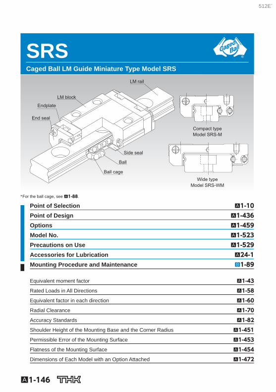
SRS Caged Ball LM Guide Miniature Type Model SRS
Model SRS-WM
Model SRS-M
Wide type
Compact type
Side seal
LM rail
LM block
Endplate
End seal
Ball
Ball cage
* For the ball cage, see A1-88 .
Point of Selection A1-10 Point of Design A1-436 Options A1-459 Model No. A1-523 Precautions on Use A1-529 Accessories for Lubrication A24-1 Mounting Procedure and Maintenance B1-89
Equivalent moment factor A1-43
Rated Loads in All Directions A1-58
Equivalent factor in each direction A1-60
Radial Clearance A1-70
Accuracy Standards A1-82
Shoulder Height of the Mounting Base and the Corner Radius A1-451
Permissible Error of the Mounting Surface A1-453
Flatness of the Mounting Surface A1-454
Dimensions of Each Model with an Option Attached A1-472
512E´
A1-147
LM G
uideSRS
Structure and Features
Caged Ball LM Guide model SRS has a structure where two raceways are incorporated into the compact body, enabling the model to receive loads in all directions, and to be used in locations where a moment is applied with a single rail. In addition, use of ball cages eliminates friction be-tween balls, thus achieving high speed, low noise, acceptable running sound, long service life, and long-term maintenance-free operation.
[Low Dust Generation] Use of ball cages eliminates friction between balls and retains lubricant, thus achieving low dust gen-eration. In addition, the LM block and LM rail use stainless steel, which is highly resistant to cor-rosion.
[Compact] Since SRS has a compact structure where the rail cross section is designed to be low and that con-tains only two rows of balls, it can be installed in space-saving locations.
[Lightweight] Since part of the LM block (e.g., around the ball relief hole) is made of resin and formed through in-sert molding, SRS is a lightweight, low inertia type of LM Guide.
512E´
A1-148
Types and Features
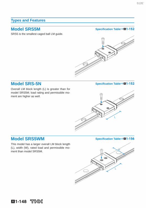
Model SRS5M Specifi cation Table⇒A1-152 SRS5 is the smallest caged ball LM guide.
Model SRS-5N Specifi cation Table⇒A1-152 Overall LM block length (L) is greater than for model SRS5M; load rating and permissible mo-ment are higher as well.
Model SRS5WM Specifi cation Table⇒A1-156 This model has a larger overall LM block length (L), width (W), rated load and permissible mo-ment than model SRS5M.
512E´
A1-149
LM G
uideSRS
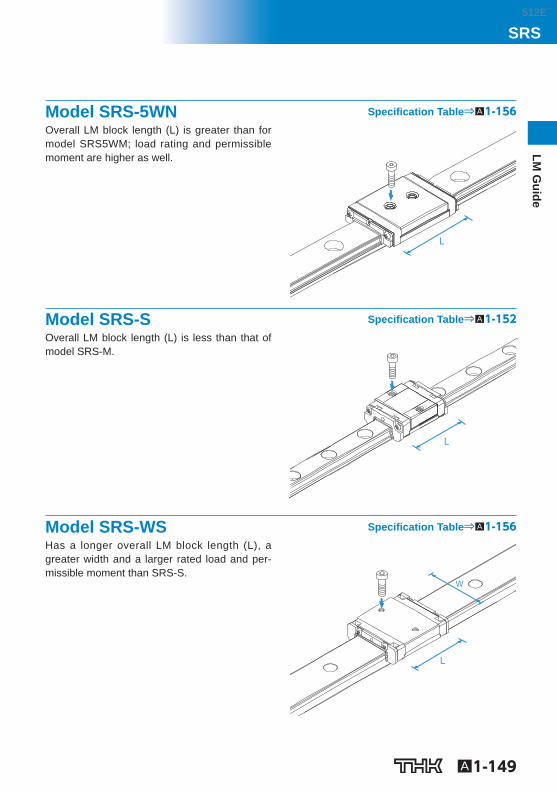
Model SRS-5WN Specifi cation Table⇒A1-156 Overall LM block length (L) is greater than for model SRS5WM; load rating and permissible moment are higher as well.
Model SRS-S Specifi cation Table⇒A1-152 Overall LM block length (L) is less than that of model SRS-M.
Model SRS-WS Specifi cation Table⇒A1-156 Has a longer overall LM block length (L), a greater width and a larger rated load and per-missible moment than SRS-S.
512E´
A1-150
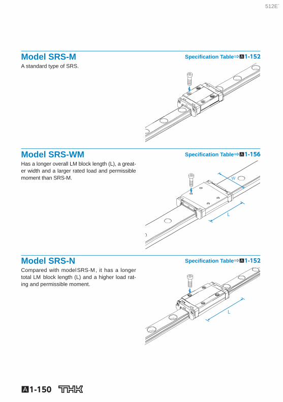
Model SRS-M Specifi cation Table⇒A1-152 A standard type of SRS.
Model SRS-WM Specifi cation Table⇒A1-156 Has a longer overall LM block length (L), a great-er width and a larger rated load and permissible moment than SRS-M.
Model SRS-N Specifi cation Table⇒A1-152 Compared with model SRS-M , it has a longer total LM block length (L) and a higher load rat-ing and permissible moment.
512E´
A1-151
LM G
uideSRS
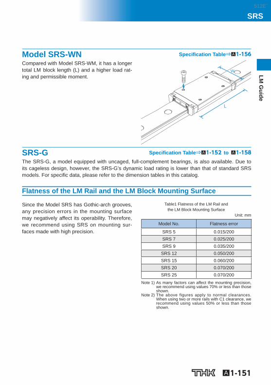
Model SRS-WN Specifi cation Table⇒A1-156 Compared with Model SRS-WM, it has a longer total LM block length (L) and a higher load rat-ing and permissible moment.
SRS-G Specifi cation Table⇒A1-152 to A1-158 The SRS-G, a model equipped with uncaged, full-complement bearings, is also available. Due to its cageless design, however, the SRS-G’s dynamic load rating is lower than that of standard SRS models. For specifi c data, please refer to the dimension tables in this catalog.
Flatness of the LM Rail and the LM Block Mounting Surface
Since the Model SRS has Gothic-arch grooves, any precision errors in the mounting surface may negatively affect its operability. Therefore, we recommend using SRS on mounting sur-faces made with high precision.
Table1 Flatness of the LM Rail and the LM Block Mounting Surface
Unit: mm
Model No. Flatness error
SRS 5 0.015/200 SRS 7 0.025/200 SRS 9 0.035/200 SRS 12 0.050/200 SRS 15 0.060/200 SRS 20 0.070/200 SRS 25 0.070/200
Note 1) As many factors can affect the mounting precision, we recommend using values 70% or less than those shown.
Note 2) The above figures apply to normal clearances. When using two or more rails with C1 clearance, we recommend using values 50% or less than those shown.
512E´
Model number coding
A1-152 Download data by searching for the corresponding model number on the Technical Support site. https://tech.thk.com
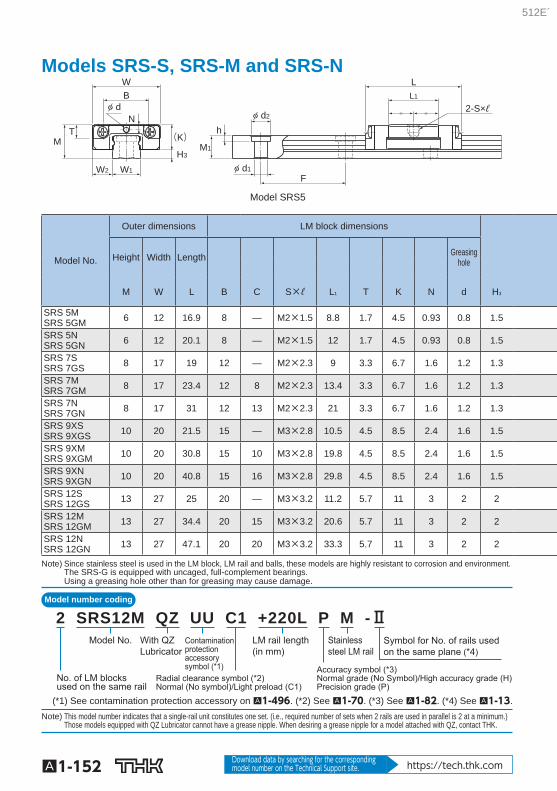
Models SRS-S, SRS-M and SRS-N
WB
NT
M
W1W2
H3
(K)h
M1
F
d2
d1
LL1
2-S×ℓ d
Model SRS5
Model No.
Outer dimensions LM block dimensions
Height Width Length Greasing hole
M W L B C S×ℓ L 1 T K N d H 3
SRS 5M SRS 5GM 6 12 16.9 8 — M2×1.5 8.8 1.7 4.5 0.93 0.8 1.5
SRS 5N SRS 5GN 6 12 20.1 8 — M2×1.5 12 1.7 4.5 0.93 0.8 1.5
SRS 7S SRS 7GS 8 17 19 12 — M2×2.3 9 3.3 6.7 1.6 1.2 1.3
SRS 7M SRS 7GM 8 17 23.4 12 8 M2×2.3 13.4 3.3 6.7 1.6 1.2 1.3
SRS 7N SRS 7GN 8 17 31 12 13 M2×2.3 21 3.3 6.7 1.6 1.2 1.3
SRS 9XS SRS 9XGS 10 20 21.5 15 — M3×2.8 10.5 4.5 8.5 2.4 1.6 1.5
SRS 9XM SRS 9XGM 10 20 30.8 15 10 M3×2.8 19.8 4.5 8.5 2.4 1.6 1.5
SRS 9XN SRS 9XGN 10 20 40.8 15 16 M3×2.8 29.8 4.5 8.5 2.4 1.6 1.5
SRS 12S SRS 12GS 13 27 25 20 — M3×3.2 11.2 5.7 11 3 2 2
SRS 12M SRS 12GM 13 27 34.4 20 15 M3×3.2 20.6 5.7 11 3 2 2
SRS 12N SRS 12GN 13 27 47.1 20 20 M3×3.2 33.3 5.7 11 3 2 2
Note) Since stainless steel is used in the LM block, LM rail and balls, these models are highly resistant to corrosion and environment. The SRS-G is equipped with uncaged, full-complement bearings. Using a greasing hole other than for greasing may cause damage.
Symbol for No. of rails usedon the same plane (*4)
LM rail length(in mm)
Contaminationprotectionaccessorysymbol (*1)
Stainless steel LM rail
Accuracy symbol (*3)Normal grade (No Symbol)/High accuracy grade (H)Precision grade (P)
Radial clearance symbol (*2)Normal (No symbol)/Light preload (C1)
No. of LM blocksused on the same rail
With QZLubricator
Model No.
2 SRS12M QZ UU C1 +220L P M -Ⅱ
(*1) See contamination protection accessory on A1-496 . (*2) See A1-70 . (*3) See A1-82 . (*4) See A1-13 . Note) This model number indicates that a single-rail unit constitutes one set. (i.e., required number of sets when 2 rails are used in parallel is 2 at a minimum.)
Those models equipped with QZ Lubricator cannot have a grease nipple. When desiring a grease nipple for a model attached with QZ, contact THK.
512E´
A1-153
LM G
uideSRS
Options⇒A1-459
d1
d2
L1
C
L
h
F
M1
4-S×ℓ
WB
N
(K)
H3
W2 W1
TM
LL1
2-S×ℓ d
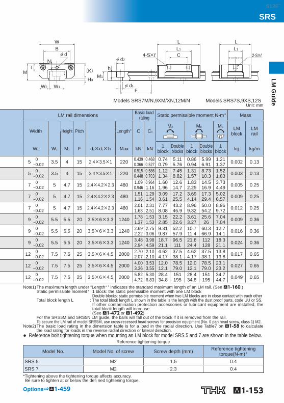
Models SRS7M/N,9XM/XN,12M/N Models SRS7S,9XS,12S Unit: mm
LM rail dimensions Basic load rating Static permissible moment N-m * Mass
Width Height Pitch Length * C C 0 M A M B M C LM
block LM rail
W 1 W 2 M 1 F d 1 ×d 2 ×h Max kN kN 1 block
Double blocks
1 block
Double blocks
1 block kg kg/m
5 0 ‒0.02 3.5 4 15 2.4×3.5×1 220 0.439
0.366 0.468 0.527
0.74 0.79
5.11 5.76
0.86 0.94
5.99 6.91
1.21 1.37 0.002 0.13
5 0 ‒0.02 3.5 4 15 2.4×3.5×1 220 0.515
0.448 0.586 0.703
1.12 1.34
7.45 8.82
1.31 1.57
8.73 10.3
1.52 1.83 0.003 0.13
7 0 ‒0.02 5 4.7 15 2.4×4.2×2.3 480 1.09
0.946 0.964 1.16
1.60 1.96
12.6 14.7
1.83 2.25
14.5 16.9
3.73 4.49 0.005 0.25
7 0 ‒0.02 5 4.7 15 2.4×4.2×2.3 480 1.51
1.16 1.29 1.54
3.09 3.61
17.2 25.5
3.69 4.14
17.3 29.4
5.02 6.57 0.009 0.25
7 0 ‒0.02 5 4.7 15 2.4×4.2×2.3 480 2.01
1.63 2.31 2.51
7.77 8.08
43.2 46.9
8.96 9.32
50.0 54.2
8.96 9.72 0.012 0.25
9 0 ‒0.02 5.5 5.5 20 3.5×6×3.3 1240 1.78
1.37 1.53 1.53
3.15 2.85
22.2 22.6
3.61 3.27
25.6 26
7.04 7.04 0.009 0.36
9 0 ‒0.02 5.5 5.5 20 3.5×6×3.3 1240 2.69
2.22 2.75 3.06
9.31 9.87
52.2 57.9
10.7 11.4
60.3 66.9
12.7 14.1 0.016 0.36
9 0 ‒0.02 5.5 5.5 20 3.5×6×3.3 1240 3.48
2.94 3.98 4.59
18.7 21.1
96.5 111
21.6 24.4
112 128
18.3 21.1 0.024 0.36
12 0 ‒0.02 7.5 7.5 25 3.5×6×4.5 2000 2.70
2.07 2.10 2.10
4.62 4.17
37.5 38.1
4.62 4.17
37.5 38.1
13.8 13.8 0.017 0.65
12 0 ‒0.02 7.5 7.5 25 3.5×6×4.5 2000 4.00
3.36 3.53 3.55
12.0 12.1
78.5 79.0
12.0 12.1
78.5 79.0
23.1 23.2 0.027 0.65
12 0 ‒0.02 7.5 7.5 25 3.5×6×4.5 2000 5.82
4.72 5.30 6.83
28.4 34.8
151 195
28.4 34.8
151 195
34.7 44.7 0.049 0.65
Note1) The maximum length under “Length * ” indicates the standard maximum length of an LM rail. (See A1-160 .) Static permissible moment * 1 block: the static permissible moment with one LM block
Double blocks: static permissible moment when two LM blocks are in close contact with each other Total block length L : The total block length L shown in the table is the length with the dust proof parts, code UU or SS.
If other contamination protection accessories or lubricant equipment are installed, the total block length will increase. (See A1-472 or A1-492 )
For the SRS5M and SRS5N LM guide, the balls will fall out of the block if it is removed from the rail. To secure the LM rail of model SRS5M, use cross-recessed head screws for precision equipment (No. 0 pan head screw, class 1) M2.
Note2) The basic load rating in the dimension table is for a load in the radial direction. Use Table7 on A1-58 to calculate the load rating for loads in the reverse radial direction or lateral direction.
● Reference bolt tightening torque when mounting an LM block for model SRS 5 and 7 are shown in the table below. Reference tightening torque
Model No. Model No. of screw Screw depth (mm) Reference tightening torque(N-m) *
SRS 5 M2 1.5 0.4 SRS 7 M2 2.3 0.4
* Tightening above the tightening torque affects accuracy. Be sure to tighten at or below the defi ned tightening torque.
512E´
Model number coding
A1-154 Download data by searching for the corresponding model number on the Technical Support site. https://tech.thk.com
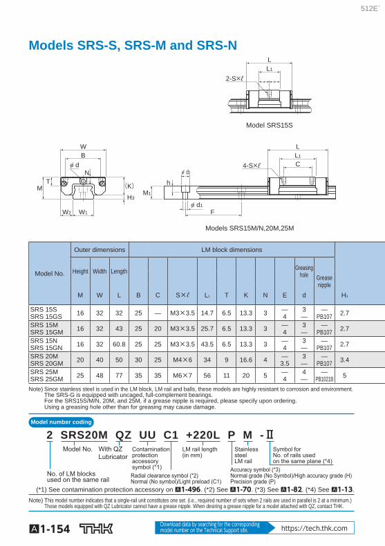
Models SRS-S, SRS-M and SRS-N
M1
h
F
L
CL1
d24-S×ℓ
d1
2-S×ℓ
LL1
Models SRS15M/N,20M,25M
Model SRS15S
(K)
H3
N
WB
d
W2 W1
TM
Model No.
Outer dimensions LM block dimensions
Height Width Length Greasing hole Grease
nipple
M W L B C S×ℓ L 1 T K N E d H 3
SRS 15S SRS 15GS 16 32 32 25 — M3×3.5 14.7 6.5 13.3 3 —
4 3 —
— PB107 2.7
SRS 15M SRS 15GM 16 32 43 25 20 M3×3.5 25.7 6.5 13.3 3 —
4 3 —
— PB107 2.7
SRS 15N SRS 15GN 16 32 60.8 25 25 M3×3.5 43.5 6.5 13.3 3 —
4 3 —
— PB107 2.7
SRS 20M SRS 20GM 20 40 50 30 25 M4×6 34 9 16.6 4 —
3.5 3 —
— PB107 3.4
SRS 25M SRS 25GM 25 48 77 35 35 M6×7 56 11 20 5 —
4 4 —
— PB1021B 5
Note) Since stainless steel is used in the LM block, LM rail and balls, these models are highly resistant to corrosion and environment. The SRS-G is equipped with uncaged, full-complement bearings. For the SRS15S/M/N, 20M, and 25M, if a grease nipple is required, please specify upon ordering. Using a greasing hole other than for greasing may cause damage.
Symbol forNo. of rails usedon the same plane (*4)
LM rail length(in mm)
Contamination protectionaccessory symbol (*1)
Stainless steelLM rail
Accuracy symbol (*3)Normal grade (No Symbol)/High accuracy grade (H)Precision grade (P)
Radial clearance symbol (*2)Normal (No symbol)/Light preload (C1)
No. of LM blocksused on the same rail
With QZLubricator
Model No.
2 SRS20M QZ UU C1 +220L P M -Ⅱ
(*1) See contamination protection accessory on A1-496 . (*2) See A1-70 . (*3) See A1-82 . (*4) See A1-13 . Note) This model number indicates that a single-rail unit constitutes one set. (i.e., required number of sets when 2 rails are used in parallel is 2 at a minimum.)
Those models equipped with QZ Lubricator cannot have a grease nipple. When desiring a grease nipple for a model attached with QZ, contact THK.
512E´
A1-155
LM G
uideSRS
Options⇒A1-459
2-S×ℓ
M1
h
F
d2
d1
(E)
N
L
CL1
4-S×ℓ
LL1
(E)
(K)
H3
WB
W2 W1
TM
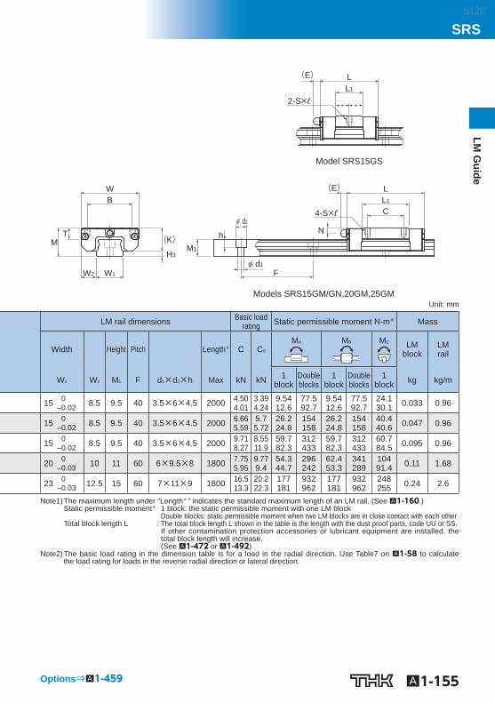
Models SRS15GM/GN,20GM,25GM
Model SRS15GS
Unit: mm
LM rail dimensions Basic load rating Static permissible moment N-m * Mass
Width Height Pitch Length * C C 0 M A M B M C LM
block LM rail
W 1 W 2 M 1 F d 1 ×d 2 ×h Max kN kN 1 block
Double blocks
1 block
Double blocks
1 block kg kg/m
15 0 ‒0.02 8.5 9.5 40 3.5×6×4.5 2000 4.50
4.01 3.39 4.24
9.54 12.6
77.5 92.7
9.54 12.6
77.5 92.7
24.1 30.1 0.033 0.96
15 0 ‒0.02 8.5 9.5 40 3.5×6×4.5 2000 6.66
5.59 5.7 5.72
26.2 24.8
154 158
26.2 24.8
154 158
40.4 40.6 0.047 0.96
15 0 ‒0.02 8.5 9.5 40 3.5×6×4.5 2000 9.71
8.27 8.55 11.9
59.7 82.3
312 433
59.7 82.3
312 433
60.7 84.5 0.095 0.96
20 0 ‒0.03 10 11 60 6×9.5×8 1800 7.75
5.95 9.77 9.4
54.3 44.7
296 242
62.4 53.3
341 289
104 91.4 0.11 1.68
23 0 ‒0.03 12.5 15 60 7×11×9 1800 16.5
13.3 20.2 22.3
177 181
932 962
177 181
932 962
248 255 0.24 2.6
Note1) The maximum length under “Length * ” indicates the standard maximum length of an LM rail. (See A1-160 .) Static permissible moment * 1 block: the static permissible moment with one LM block
Double blocks: static permissible moment when two LM blocks are in close contact with each other Total block length L : The total block length L shown in the table is the length with the dust proof parts, code UU or SS.
If other contamination protection accessories or lubricant equipment are installed, the total block length will increase. (See A1-472 or A1-492 )
Note2) The basic load rating in the dimension table is for a load in the radial direction. Use Table7 on A1-58 to calculate the load rating for loads in the reverse radial direction or lateral direction.
512E´
Model number coding
A1-156 Download data by searching for the corresponding model number on the Technical Support site. https://tech.thk.com
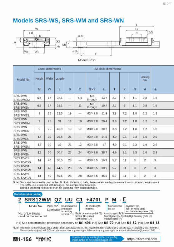
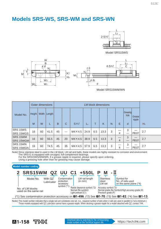
Models SRS-WS, SRS-WM and SRS-WN
Model SRS5
W
NT
M
W1W2
H3
(K)
d
h
2-S
M1
F
LL1
d2
d1
C
Model No.
Outer dimensions LM block dimensions
Height Width Length Greasing hole
M W L B C S×ℓ L 1 T K N d H 3
SRS 5WM SRS 5WGM
6.5 17 22.1 — 6.5 M3 through 13.7 2.7 5 1.1 0.8 1.5
SRS 5WN SRS 5WGN
6.5 17 28.1 — 11 M3 through 19.7 2.7 5 1.1 0.8 1.5
SRS 7WS SRS 7WGS
9 25 22.5 19 — M3×2.8 11.9 3.8 7.2 1.8 1.2 1.8
SRS 7WM SRS 7WGM
9 25 31 19 10 M3×2.8 20.4 3.8 7.2 1.8 1.2 1.8
SRS 7WN SRS 7WGN
9 25 40.9 19 17 M3×2.8 30.3 3.8 7.2 1.8 1.2 1.8
SRS 9WS SRS 9WGS
12 30 26.5 21 — M3×2.8 14.5 4.9 9.1 2.3 1.6 2.9
SRS 9WM SRS 9WGM
12 30 39 21 12 M3×2.8 27 4.9 9.1 2.3 1.6 2.9
SRS 9WN SRS 9WGN
12 30 50.7 23 24 M3×2.8 38.7 4.9 9.1 2.3 1.6 2.9
SRS 12WS SRS 12WGS
14 40 30.5 28 — M3×3.5 16.9 5.7 11 3 2 3
SRS 12WM SRS 12WGM
14 40 44.5 28 15 M3×3.5 30.9 5.7 11 3 2 3
SRS 12WN SRS 12WGN
14 40 59.5 28 28 M3×3.5 45.9 5.7 11 3 2 3
Note) Since stainless steel is used in the LM block, LM rail and balls, these models are highly resistant to corrosion and environment. The SRS-G is equipped with uncaged, full-complement bearings. Using a greasing hole other than for greasing may cause damage.
Symbol forNo. of rails usedon the same plane (*4)
LM rail length(in mm)
Contamination protectionaccessory symbol (*1)
Stainless steelLM rail
Accuracy symbol (*3)Normal grade (No Symbol)/High accuracy grade (H)Precision grade (P)
Radial clearance symbol (*2)Normal (No symbol)/Light preload (C1)
No. of LM blocksused on the same rail
With QZLubricator
Model No.
2 SRS12WM QZ UU C1 +470L P M -Ⅱ
(*1) See contamination protection accessory on A1-496 . (*2) See A1-70 . (*3) See A1-82 . (*4) See A1-13 . Note) This model number indicates that a single-rail unit constitutes one set. (i.e., required number of sets when 2 rails are used in parallel is 2 at a minimum.)
Those models equipped with QZ Lubricator cannot have a grease nipple. When desiring a grease nipple for a model attached with QZ, contact THK.
512E´
A1-157
LM G
uideSRS
Options⇒A1-459
d
L1
C
L
F d1
hM1
d2
WB
(K)H3
W1W2
NT
M
4-S×ℓ
LL1
2-S×ℓ
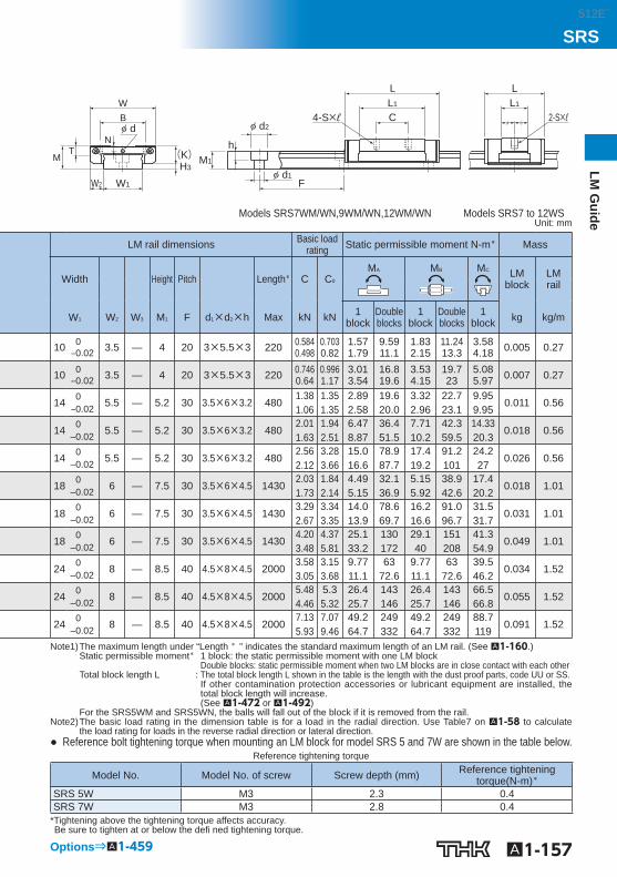
Models SRS7WM/WN,9WM/WN,12WM/WN Models SRS7 to 12WS Unit: mm
LM rail dimensions Basic load rating Static permissible moment N-m * Mass
Width Height Pitch Length * C C 0 M A M B M C LM
block LM rail
W 1 W 2 W 3 M 1 F d 1 ×d 2 ×h Max kN kN 1 block
Double blocks
1 block
Double blocks
1 block kg kg/m
10 0 ‒0.02 3.5 — 4 20 3×5.5×3 220 0.584
0.498 0.703 0.82
1.57 1.79
9.59 11.1
1.83 2.15
11.24 13.3
3.58 4.18 0.005 0.27
10 0 ‒0.02 3.5 — 4 20 3×5.5×3 220 0.746
0.64 0.996 1.17
3.01 3.54
16.8 19.6
3.53 4.15
19.7 23
5.08 5.97 0.007 0.27
14 0 ‒0.02 5.5 — 5.2 30 3.5×6×3.2 480
1.38 1.06
1.35 1.35
2.89 2.58
19.6 20.0
3.32 2.96
22.7 23.1
9.95 9.95
0.011 0.56
14 0 ‒0.02 5.5 — 5.2 30 3.5×6×3.2 480
2.01 1.63
1.94 2.51
6.47 8.87
36.4 51.5
7.71 10.2
42.3 59.5
14.33 20.3
0.018 0.56
14 0 ‒0.02 5.5 — 5.2 30 3.5×6×3.2 480
2.56 2.12
3.28 3.66
15.0 16.6
78.9 87.7
17.4 19.2
91.2 101
24.2 27
0.026 0.56
18 0 ‒0.02 6 — 7.5 30 3.5×6×4.5 1430
2.03 1.73
1.84 2.14
4.49 5.15
32.1 36.9
5.15 5.92
38.9 42.6
17.4 20.2
0.018 1.01
18 0 ‒0.02 6 — 7.5 30 3.5×6×4.5 1430
3.29 2.67
3.34 3.35
14.0 13.9
78.6 69.7
16.2 16.6
91.0 96.7
31.5 31.7
0.031 1.01
18 0 ‒0.02 6 — 7.5 30 3.5×6×4.5 1430
4.20 3.48
4.37 5.81
25.1 33.2
130 172
29.1 40
151 208
41.3 54.9
0.049 1.01
24 0 ‒0.02 8 — 8.5 40 4.5×8×4.5 2000
3.58 3.05
3.15 3.68
9.77 11.1
63 72.6
9.77 11.1
63 72.6
39.5 46.2
0.034 1.52
24 0 ‒0.02 8 — 8.5 40 4.5×8×4.5 2000
5.48 4.46
5.3 5.32
26.4 25.7
143 146
26.4 25.7
143 146
66.5 66.8
0.055 1.52
24 0 ‒0.02 8 — 8.5 40 4.5×8×4.5 2000
7.13 5.93
7.07 9.46
49.2 64.7
249 332
49.2 64.7
249 332
88.7 119
0.091 1.52
Note1) The maximum length under “Length * ” indicates the standard maximum length of an LM rail. (See A1-160 .) Static permissible moment * 1 block: the static permissible moment with one LM block
Double blocks: static permissible moment when two LM blocks are in close contact with each other Total block length L : The total block length L shown in the table is the length with the dust proof parts, code UU or SS.
If other contamination protection accessories or lubricant equipment are installed, the total block length will increase. (See A1-472 or A1-492 )
For the SRS5WM and SRS5WN, the balls will fall out of the block if it is removed from the rail. Note2) The basic load rating in the dimension table is for a load in the radial direction. Use Table7 on A1-58 to calculate
the load rating for loads in the reverse radial direction or lateral direction. ● Reference bolt tightening torque when mounting an LM block for model SRS 5 and 7W are shown in the table below.
Reference tightening torque
Model No. Model No. of screw Screw depth (mm) Reference tightening torque(N-m) *
SRS 5W M3 2.3 0.4 SRS 7W M3 2.8 0.4
* Tightening above the tightening torque affects accuracy. Be sure to tighten at or below the defi ned tightening torque.
512E´
Model number coding
A1-158 Download data by searching for the corresponding model number on the Technical Support site. https://tech.thk.com
Models SRS-WS, SRS-WM and SRS-WN
Model SRS15WM/WN
Model SRS15WS
d
WB
H3
(K)MT
N
W2
W3
W1
M1
h
F
L
CL1
LL1
d2
d1
4-S×ℓ
2-S×ℓ
Model No.
Outer dimensions LM block dimensions
Height Width Length Greasing hole Grease
nipple
M W L B C S×ℓ L 1 T K N E d H 3
SRS 15WS SRS 15WGS
16 60 41.5 45 — M4×4.5 24.9 6.5 13.3 3 — 4
3 —
— PB107 2.7
SRS 15WM SRS 15WGM
16 60 55.5 45 20 M4×4.5 38.9 6.5 13.3 3 — 4
3 —
— PB107 2.7
SRS 15WN SRS 15WGN
16 60 74.5 45 35 M4×4.5 57.9 6.5 13.3 3 — 4
3 —
— PB107 2.7
Note) Since stainless steel is used in the LM block, LM rail and balls, these models are highly resistant to corrosion and environment. The SRS-G is equipped with uncaged, full-complement bearings. For the SRS15WS/WM/WN, if a grease nipple is required, please specify upon ordering. Using a greasing hole other than for greasing may cause damage.
Symbol forNo. of rails usedon the same plane (*4)
LM rail length(in mm)
Contamination protectionaccessory symbol (*1)
Stainless steelLM rail
Accuracy symbol (*3)Normal grade (No Symbol)/High accuracy grade (H)Precision grade (P)
Radial clearance symbol (*2)Normal (No symbol)/Light preload (C1)
No. of LM blocksused on the same rail
With QZLubricator
Model No.
2 SRS15WM QZ UU C1 +550L P M -Ⅱ
(*1) See contamination protection accessory on A1-496 . (*2) See A1-70 . (*3) See A1-82 . (*4) See A1-13 . Note) This model number indicates that a single-rail unit constitutes one set. (i.e., required number of sets when 2 rails are used in parallel is 2 at a minimum.)
Those models equipped with QZ Lubricator cannot have a grease nipple. When desiring a grease nipple for a model attached with QZ, contact THK.
512E´
A1-159
LM G
uideSRS
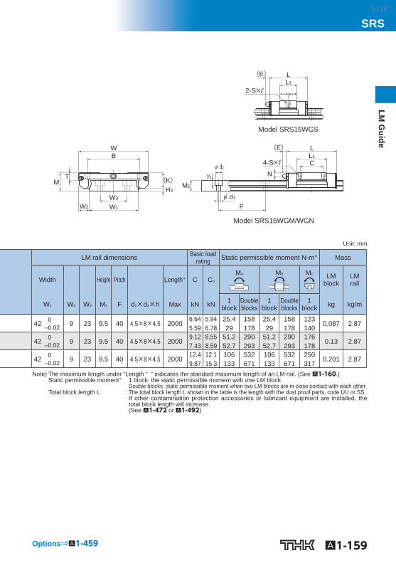
Model SRS15WGM/WGN
Model SRS15WGS
WB
H3
(K)MT
W2
W3
W1
(E)
M1
F
N
L
CL1
LL1
d2
d1
4-S×ℓ
2-S×ℓ
(E)
h
Unit: mm
LM rail dimensions Basic load rating Static permissible moment N-m * Mass
Width Height Pitch Length * C C 0 M A M B M C LM
block LM rail
W 1 W 2 W 3 M 1 F d 1 ×d 2 ×h Max kN kN 1 block
Double blocks
1 block
Double blocks
1 block kg kg/m
42 0 ‒0.02 9 23 9.5 40 4.5×8×4.5 2000
6.64 5.59
5.94 6.78
25.4 29
158 178
25.4 29
158 178
123 140
0.087 2.87
42 0 ‒0.02 9 23 9.5 40 4.5×8×4.5 2000
9.12 7.43
8.55 8.59
51.2 52.7
290 293
51.2 52.7
290 293
176 178
0.13 2.87
42 0 ‒0.02 9 23 9.5 40 4.5×8×4.5 2000
12.4 9.87
12.1 15.3
106 133
532 671
106 133
532 671
250 317
0.201 2.87
Note) The maximum length under “Length * ” indicates the standard maximum length of an LM rail. (See A1-160 .) Static permissible moment * 1 block: the static permissible moment with one LM block
Double blocks: static permissible moment when two LM blocks are in close contact with each other Total block length L : The total block length L shown in the table is the length with the dust proof parts, code UU or SS.
If other contamination protection accessories or lubricant equipment are installed, the total block length will increase. (See A1-472 or A1-492 )
Options⇒A1-459
512E´
A1-160
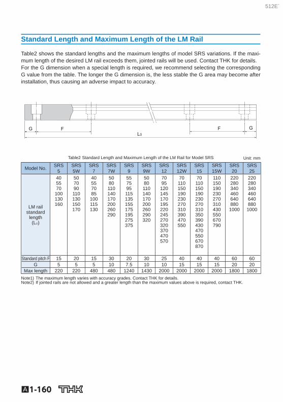
Standard Length and Maximum Length of the LM Rail
Table2 shows the standard lengths and the maximum lengths of model SRS variations. If the maxi-mum length of the desired LM rail exceeds them, jointed rails will be used. Contact THK for details. For the G dimension when a special length is required, we recommend selecting the corresponding G value from the table. The longer the G dimension is, the less stable the G area may become after installation, thus causing an adverse impact to accuracy.
G L0
F F G
Table2 Standard Length and Maximum Length of the LM Rail for Model SRS Unit: mm
Model No. SRS 5
SRS 5W
SRS 7
SRS 7W
SRS 9
SRS 9W
SRS 12
SRS 12W
SRS 15
SRS 15W
SRS 20
SRS 25
LM rail standard
length (L O )
40 55 70
100 130 160
50 70 90 110 130 150 170
40 55 70 85
100 115 130
50 80 110 140 170 200 260 290
55 75 95 115 135 155 175 195 275 375
50 80 110 140 170 200 260 290 320
70 95
120 145 170 195 220 245 270 320 370 470 570
70 110 150 190 230 270 310 390 470 550
70 110 150 190 230 270 310 350 390 430 470 550 670 870
110 150 190 230 270 310 430 550 670 790
220 280 340 460 640 880 1000
220 280 340 460 640 880 1000
Standard pitch F 15 20 15 30 20 30 25 40 40 40 60 60 G 5 5 5 10 7.5 10 10 15 15 15 20 20
Max length 220 220 480 480 1240 1430 2000 2000 2000 2000 1800 1800 Note1) The maximum length varies with accuracy grades. Contact THK for details. Note2) If jointed rails are not allowed and a greater length than the maximum values above is required, contact THK.
512E´
A1-161
LM G
uideSRS
512E´


