Sri Lanka Sustainable Energy Authority - energy.gov.lk · Sri Lanka Sustainable Energy Authority...
58
Sri Lanka Sustainable Energy Authority
Transcript of Sri Lanka Sustainable Energy Authority - energy.gov.lk · Sri Lanka Sustainable Energy Authority...

Sri Lanka Sustainable Energy Authority

Sri Lanka Sustainable Energy Authority

Sri Lanka Sustainable Energy Authority
Code of practice for energy efficient buildings
in Sri Lankais published
On this date of 30th June 2009 Under Clause 36 (g) of Sri Lanka
Sustainable Energy Authority Act
Director General Sri Lanka Sustainable Energy Authority
3G- 17, BMICH Colombo 07
Telephone: 011-2677445
Sri Lanka Sustainable Energy Authority
(I)
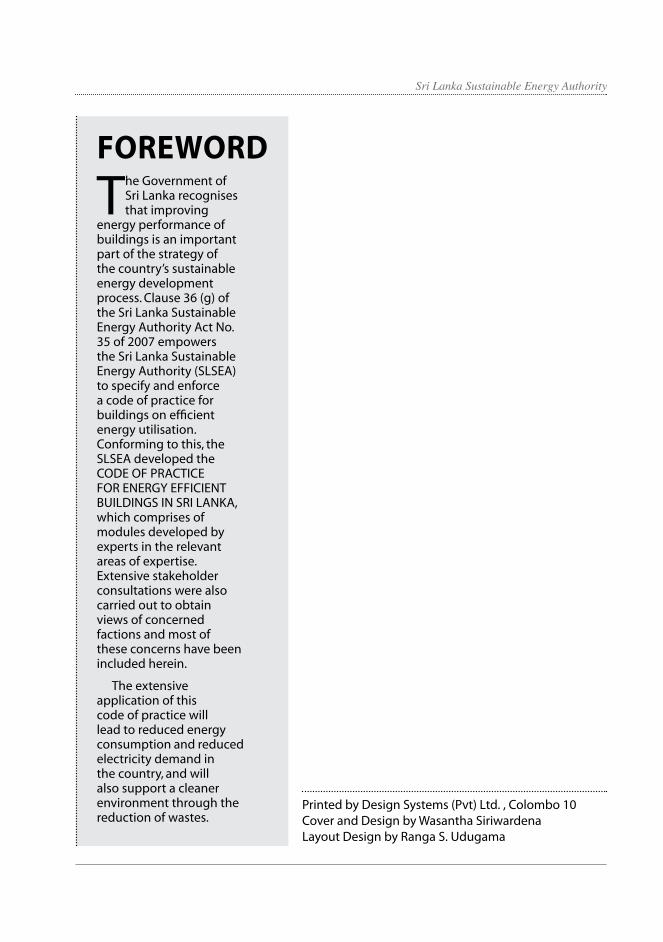
The Government of Sri Lanka recognises that improving
energy performance of buildings is an important part of the strategy of the country’s sustainable energy development process. Clause 36 (g) of the Sri Lanka Sustainable Energy Authority Act No. 35 of 2007 empowers the Sri Lanka Sustainable Energy Authority (SLSEA) to specify and enforce a code of practice for buildings on efficient energy utilisation. Conforming to this, the SLSEA developed the CODE OF PRACTICE FOR ENERGY EFFICIENT BUILDINGS IN SRI LANKA, which comprises of modules developed by experts in the relevant areas of expertise. Extensive stakeholder consultations were also carried out to obtain views of concerned factions and most of these concerns have been included herein.
The extensive application of this code of practice will lead to reduced energy consumption and reduced electricity demand in the country, and will also support a cleaner environment through the reduction of wastes.
Foreword
Printed by Design Systems (Pvt) Ltd. , Colombo 10Cover and Design by Wasantha SiriwardenaLayout Design by Ranga S. Udugama

Sri Lanka Sustainable Energy Authority
(II)
Acknowledgement
T h e first Energy Efficiency Building Code (EEBC) of Sri Lanka was developed by the Ceylon Electricity
Board in 2000. This EEBC (2000) was the major precursor which prompted the Sri Lanka Sustainable Energy Authority to develop a new code for energy efficient buildings by reviewing and amending the extant EEBC, making allowance for advancing technologies and modern society requirements.
Our utmost gratitude goes to Mr. M.M.C. Ferdinando Secretary to the Ministry of Power and Energy, Mr. Ananda S. Gunasekara, founder Chairman of the SLSEA and Dr. Krishan Deheragoda, Chairman of the SL SEA for their continuous support, guidance and encouragement we received throughout.
The CODE OF PRACTICE FOR ENERGY EFFICIENT BUILDINGS IN SRI LANKA is a result of exceptional team work conducted by leading consultants in Sri Lanka. Hereby, we express our gratitude to:
The subcommittee on implementation mechanism
M.S. Jayalath (Consultant)Wijitha Perera (Consultant)Prasanna Wijetunga (Deputy Director, Urban Development Authority)Mrs. Priyantha Ranawaka (Senior Engineer, Colombo Municipal Council)
The Subcommittee on lighting Tissa Gunasena (Consultant) Buddika Samarasekara (Electrical Engineer, Ceylon Electricity Board) Sharmila Ragunathan (Head-Projects, Hayleys)
The subcommittee on ventilation and air conditioningWijitha Perera (Consultant)Wimal Jayakody (Consultant)Franklin Silva (Consultant)
The subcommittee on building envelope
Rahula Attalage (Professor, University of Moratuwa) Thishan Jayasinghe (Professor, University of Moratuwa) Narein Perera (Senior Lecturer, University of Moratuwa)
The subcommittee on electrical power and distribution
Ranil Senaratna (Director, Fentons)Rienzie Fernando (Consultant)
The subcommittee on pumps, motors and service water heating
Dr. A.G.T. Sugathapala (Senior Lecturer, University of Moratuwa)D.D. Ananda Namal (Deputy General Manager, services, NERD Centre)
The project was managed by the Department of Energy Management of the SLSEA. We extend our gratitude to;
Harsha Wickramasinghe (Deputy Director General-Operations, SLSEA)Upali Daranagama (Deputy-Director General-Strategy, SLSEA)M.M.R. Pathmasiri (Director Energy Management, SLSEA)Chamila Jayasekara (Head-Energy Efficient Systems, SLSEA)Ms. Asanka Rahubadda (Engineer, Energy Efficiency, SLSEA)
Our heartfelt thanks go to the following institutions for their support in making this endeavour a success.
The Urban Development AuthorityThe Colombo Municipal CouncilThe University of Moratuwa

Sri Lanka Sustainable Energy Authority
(III)
1. Introduction .............................................................................................................................. 11.1 Purpose ....................................................................................................................................... 11.2 Exemptions ................................................................................................................................ 11.3 Compliance Requirements .................................................................................................. 11.4 Implementation ....................................................................................................................... 1
2. Lighting ....................................................................................................................................... 32.1 General Principles of Energy Efficient Lighting Practice ........................................... 32.2 Mandatory Requirements .................................................................................................... 42.2.1 Lighting Controls ..................................................................................................................... 42.2.2 Maximum Allowable Power for Illumination Systems ............................................... 42.2.3 Building Exterior Lighting Power ....................................................................................... 52.3 Prescriptive Requirements ................................................................................................... 62.3.1 General and Task Lighting Considerations ..................................................................... 62.3.2 Selection of appropriate components ............................................................................ 72.4 Strategy for energy efficient lighting ............................................................................... 92.5 Submission Procedure ........................................................................................................... 102.6 Annexes ...................................................................................................................................... 10
3. Ventilation and Air Conditioning ....................................................................................... 103.1 Mandatory requirements ..................................................................................................... 103.1.1 Load Calculations .................................................................................................................... 103.1.2 System and Equipment Sizing ............................................................................................ 113.1.3 Fan System Design Criteria .................................................................................................. 113.1.4 Pumping system design criteria ........................................................................................ 113.1.5 Separate Air Distribution Systems ..................................................................................... 123.1.6 Temperature Controls ............................................................................................................ 123.1.7 Off-Hour Controls .................................................................................................................... 133.1.8 Piping Insulation ...................................................................................................................... 133.1.9 Air Handling System Insulation .......................................................................................... 143.1.10 Air Handling System Ducts .................................................................................................. 143.1.11 A/C Equipment ......................................................................................................................... 143.1.12 Testing, Adjusting, Balancing and Commissioning ..................................................... 153.1.13 Water Treatment ...................................................................................................................... 153.1.14 Maintenance ............................................................................................................................. 153.1.15 Submission Procedure ........................................................................................................... 193.2 Annexes ...................................................................................................................................... 19
4. Building Envelop ...................................................................................................................... 194.1 General Principles of Energy Efficient Envelop Design .............................................. 194.2 Mandatory requirements ..................................................................................................... 204.3 Prescriptive Requirements ................................................................................................... 204.4. Compliance ................................................................................................................................ 214.5 Submission procedure .......................................................................................................... 214.6 Annexes ...................................................................................................................................... 21
Table of Contents
Sri Lanka Sustainable Energy Authority
5. Electric Power and Distribution ........................................................................................... 225.1 General Principles of Energy Efficient Electrical Power Distribution ..................... 225.2 Mandatory requirements ...................................................................................................... 225.2.1 Electrical Distribution System .............................................................................................. 225.2.2 Transformers............................................................................................................................... 235.2.3 Electric Motors ........................................................................................................................... 235.3 Prescriptive Requirements .................................................................................................... 245.4 Design Considerations............................................................................................................ 245.5 Submission Procedure ............................................................................................................ 255.6 Annexes........................................................................................................................................ 25
6. Service Water Heating............................................................................................................. 256.1 General Principles ..................................................................................................................... 256.2 Sizing of Systems ...................................................................................................................... 266.3 Mandatory requirements ...................................................................................................... 266.3.1 Water Heating Equipment Efficiency ................................................................................ 266.3.2 Service Water Heating Piping Insulation .......................................................................... 266.3.3 Service Water Heating System Controls ........................................................................... 276.4 Prescriptive Requirements .................................................................................................... 276.4.1 Temperature Limits .................................................................................................................. 276.4.2 Heat Traps .................................................................................................................................... 276.5 Design Considerations............................................................................................................ 276.5.1 Supplementary Service Water Heating Systems ........................................................... 276.6 Submission Procedure ............................................................................................................ 276.7 Annexes........................................................................................................................................ 27
Annex 1: Definitions, Abbreviations & Acronyms .......................................................................... 28Annex 2: Lighting...................................................................................................................................... 34Annex 3: Ventilation & Air Conditioning ........................................................................................... 43Annex 4: Building Envelop .................................................................................................................... 46Annex 5: Electrical Power and Distribution .................................................................................... 49Annex 6: Service Water Heating ......................................................................................................... 49
(IV)
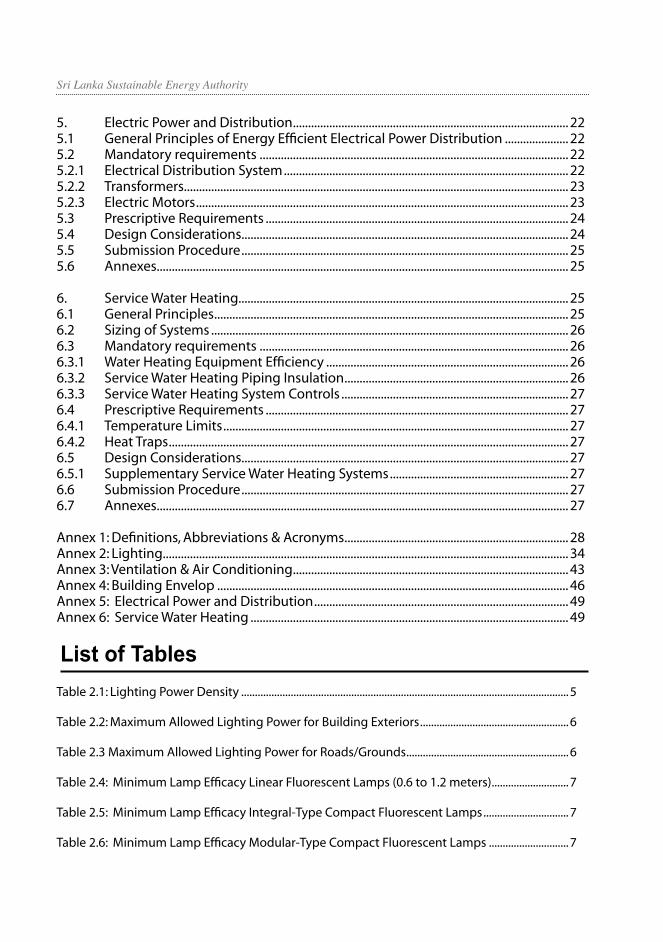
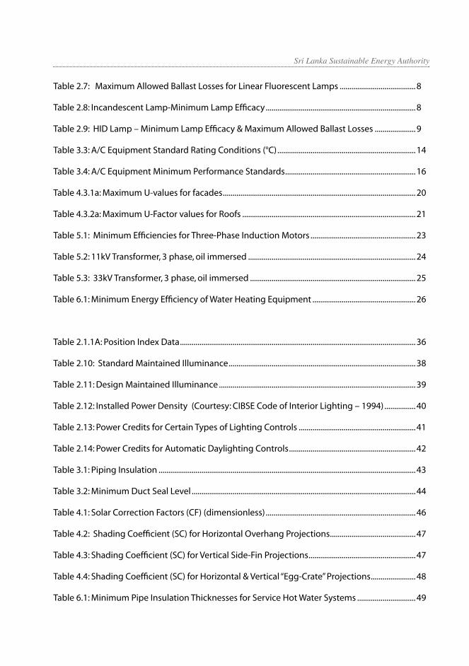
List of TablesTable 2.1: Lighting Power Density .......................................................................................................................5
Table 2.2: Maximum Allowed Lighting Power for Building Exteriors ......................................................6
Table 2.3 Maximum Allowed Lighting Power for Roads/Grounds ...........................................................6
Table 2.4: Minimum Lamp Efficacy Linear Fluorescent Lamps (0.6 to 1.2 meters) ............................7
Table 2.5: Minimum Lamp Efficacy Integral-Type Compact Fluorescent Lamps ...............................7
Table 2.6: Minimum Lamp Efficacy Modular-Type Compact Fluorescent Lamps .............................7
Sri Lanka Sustainable Energy Authority
(V)
Table 2.7: Maximum Allowed Ballast Losses for Linear Fluorescent Lamps .......................................8
Table 2.8: Incandescent Lamp-Minimum Lamp Efficacy .............................................................................8
Table 2.9: HID Lamp – Minimum Lamp Efficacy & Maximum Allowed Ballast Losses .....................9
Table 3.3: A/C Equipment Standard Rating Conditions (°C) .......................................................................14
Table 3.4: A/C Equipment Minimum Performance Standards ...................................................................16
Table 4.3.1a: Maximum U-values for facades ...................................................................................................20
Table 4.3.2a: Maximum U-Factor values for Roofs .........................................................................................21
Table 5.1: Minimum Efficiencies for Three-Phase Induction Motors ......................................................23
Table 5.2: 11kV Transformer, 3 phase, oil immersed ......................................................................................24
Table 5.3: 33kV Transformer, 3 phase, oil immersed .....................................................................................25
Table 6.1: Minimum Energy Efficiency of Water Heating Equipment .....................................................26
Table 2.1.1A: Position Index Data .........................................................................................................................36
Table 2.10: Standard Maintained Illuminance ................................................................................................38
Table 2.11: Design Maintained Illuminance .....................................................................................................39
Table 2.12: Installed Power Density (Courtesy: CIBSE Code of Interior Lighting – 1994) ................40
Table 2.13: Power Credits for Certain Types of Lighting Controls ............................................................41
Table 2.14: Power Credits for Automatic Daylighting Controls .................................................................42
Table 3.1: Piping Insulation ....................................................................................................................................43
Table 3.2: Minimum Duct Seal Level ...................................................................................................................44
Table 4.1: Solar Correction Factors (CF) (dimensionless) .............................................................................46
Table 4.2: Shading Coefficient (SC) for Horizontal Overhang Projections ............................................47
Table 4.3: Shading Coefficient (SC) for Vertical Side-Fin Projections .......................................................47
Table 4.4: Shading Coefficient (SC) for Horizontal & Vertical “Egg-Crate” Projections .......................48
Table 6.1: Minimum Pipe Insulation Thicknesses for Service Hot Water Systems ..............................49

Sri Lanka Sustainable Energy Authority
The CODE OF PRACTICE FOR ENERGY EFFICIENT BUILDINGS IN SRI LANKA was compiled by the Sri Lanka Sustainable Energy Authority (SLSEA) upon reviewing and amending the Energy Efficient Building Code [CEB - 2000].
1.1 PurposeTo introduce energy efficient design and/
or retrofits to commercial buildings, industrial facilities and large scale housing schemes to enable designing, construction and maintenance to be carried out under minimal energy consumption without compromising the building’s function, and/or the comfort and health of occupants.
To set criteria and minimum standards for energy efficiency in design and/or retrofits in commercial buildings and to provide criteria for determining compliance.
To encourage energy efficiency designs exceeding minimum standards.
1.2 ExemptionsThe code however does not cover energy
consumption processes of equipment that are in the buildings other than in the form of building elements.
1.3 Compliance Requirements
This CODE OF PRACTICE FOR ENERGY EFFICIENT BUILDINGS IN SRI LANKA sets forth the requirements for design and/or retrofit of commercial buildings and industrial installations.
This code of practice covers the following building elements:
a) Building envelop
b) Ventilation & Air conditioning
c) Lighting
d) Electrical power and distribution
e) Service Water Heating
All commercial buildings, industrial facilities and large scale housing developments having one or more of the following features,
a) Four or more stories
b) Floor area of 500 m2 or more
c) Electrical power demand of 100 kVA or more
d) Air-conditioning cooling capacity of 350 kW (output) or more are subject to the regulations of this code.
This code covers only the energy performance aspects of a given building. The code in no way relates to the health and safety aspects of personnel during the construction phase of the building, but importantly, does not supersede any other existing statutory criteria and/or codes pertaining to the above aspects. This code may be used as an additional set of regulations supplementing the already existing regulations and requirements.
1.4 ImplementationThis programme would be implemented
through Urban Development Authority (UDA), Provincial Councils and Local Authorities. All new buildings with one or more features stated in 1.3.3 are expected to conform to the building code regulations. The SLSEA will provide the necessary assistance to the Local Authorities to evaluate sections regarding energy efficiency aspects in the CODE in all building applications as necessary. Programmes to develop an effective implementation mechanism will include the selection of implementation mechanism and consultations of the local government bodies to understand the existing building approval process and incorporate practices given in this CODE to the existing structures.
1
1. Introduction

Sri Lanka Sustainable Energy Authority
1.4.1 Implementing agencies
a. SLSEA –The responsible Agency for the implementation of CODE
b. UDA, Provincial Councils and Local Authorities (Municipal Councils, Urban Councils and Pradeshiya Sabha) - implementing partners of the CODE
1.4.2 Implementation mechanism
The code in the present form is basically to be used for Commercial Buildings. Industrial buildings, Hotels and large apartment complexes are to be brought in subsequently. The method of implementation therefore is expected to cover all above areas.
1. The UDA, Colombo Municipal Council and other Municipal Councils in the country together with all other Local Government Establishments will be the major partners responsible for implementing these regulations from the planning stage. These organisations will here in after be referred to as Implementing Authorities.
2. The Implementing Authorities will introduce an additional compliance requirement (similar to the fire code compliance) as an integral part of the building plan approval procedure.
3. The relevant section of the building permit application, with the relevant drawings and the submittals will be forwarded to a special Code compliance certifying body specifically set up for the purpose.
4. The Code compliance certifying body will be established by the SLSEA. This body will comprise of two committees as appointed by the SLSEA. The Monitoring and Approval committee will be empowered to recommend approval of the building application. This committee will be assisted by the Technical Evaluation Committee, which, after carefully studying the submittals, will submit their recommendations to the Monitoring and Approval committee.
5. The Monitoring and Approval committee
will consist of senior specialists in the relevant fields covering the entire Code. They will be selected and appointed by the SLSEA.
6. The Technical Evaluation Committee will consist of technically qualified persons having adequate experience in the areas of specialty coming under the Code and who have been trained in the implementation procedure for the Code. This committee will process the submittals and make their recommendations to the Monitoring and Approval Committee.
7. The SLSEA will obtain the services of existing professional associations and bodies to obtain their services as partners or obtain their assistance in selecting suitable persons for the Technical Evaluation Committee.
8. The Monitoring and Approval Committee will make the final recommendation to the Responsible Agency (SLSEA). The SLSEA will issue a letter of compliance to the relevant agency for eligible projects, considering the recommendations of the Monitoring and Approval committee. It will be the Code compliance approval for the project.
9. The inspection of the building on completion will be carried out either by the Technical Evaluation committee or any other organisation or committee appointed by the SLSEA. Certificate of Conformity will be issued for the projects, which shall be successful at this stage of evaluation. Certificate of Conformity will be the final document expressing the compliance of the certified building to the Code. The compliance certificate will be issued for a specific period of time (3 – 5 years). The certificate needs to be revalidated subsequent to an inspection thereafter.
10. The buildings complying with the Code will be given a ‘Star Rating’ depending on the level of compliance. A marking scheme needs to be worked out for this purpose.
32

Sri Lanka Sustainable Energy Authority
2.1 General Principles of Energy Efficient Lighting Practice
Lighting is, perhaps, the single largest consumer of energy (kilowatt hours) in a building (other than when air-conditioning is used). It also contributes largely towards increasing of cooling loads in buildings in tropical climates, as lighting generates heat, which in turn results in higher consumption of energy for air conditioning requirements.
There are a number of technologies available today, that can significantly reduce this component but it has to be done with utmost care as it needs to be accepted by the Occupants who actually experience the lighting installation. Further, latest research has revealed that qualitative aspects of lighting can bring about increase in productivity and therefore, it is a matter of arriving at solutions, without compromising the qualitative aspects, to reduce energy. This also calls for creativity on the part of lighting designers, for instance, to maximise the use of daylight and apply dynamic lighting solutions and colours in a sensible way, without compromising safety aspects.
This CODE will set the maximum allowable loads for building lighting systems as well as lower limits for the acceptable efficiencies for commonly used lighting components (lamps and ballasts). The Lighting Designer therefore is to face the challenge of using this CODE as a minimum energy performance standard to develop lighting systems that balance appealing and effective visual environments with minimal energy usage.
2.1.1 Objective
The objective of this section of the CODE is to use minimal electrical energy to provide lighting to the quantity and quality of standards. It is however necessary to evaluate the equipment, techniques and services available for both existing and proposed installations in order to meet these requirements.
Following are six basic rules for achieving energy efficiency in lighting.
1. Use the most efficient but suitable light source
2. Ensure efficient usage of lamp light output
3. Ensure proper maintenance of lighting equipment
4. Use well-designed energy efficient lighting schemes
5. Establish controlled switching operations and maximise use of daylight
6. Consider appropriate interior décor: use light-colours whenever possible.
2.1.2 Spaces covered
a) Interior spaces of buildings
b) Exterior areas including facades, entrances, exit ways, loading docks etc.
c) Roads, grounds and other areas including open air/ enclosed areas where lighting is installed and powered by the building electrical system.
2.1.3 Exemptions
a) Commercial greenhouses
b) Lighting power for theatrical productions, television broadcasting, portions of entertainment facilities such as dancing floors in hotel ballrooms, night-clubs, discos and casinos where lighting is an essential technical element of the function performed.
c) Theatre facilities in medical and dental applications
d) Outdoor sports facilities
e) Exterior lighting of public monuments
f ) Special applications such as research laboratories, museums etc.
g) Emergency lighting that is automatically OFF during normal operation
2. Lighting
32

Sri Lanka Sustainable Energy Authority
h) High-risk security areas identified by local ordinances or regulation or by security or safety personnel
2.2 Mandatory Requirements2.2.1 Lighting Controls
The two main factors involved in the energy efficient lighting systems are the lamp wattage and the duration of its operation. Both these factors are equally important and could be made to contribute to energy efficiency through ‘Lighting Controls’.
2.2.1.1 Area Controls
The simplest way to improve lighting efficiency is to turn off lights when they are not in use. All lighting systems must have switching or control capabilities to allow lights to be turned off when they are not required.
a) All spaces enclosed by walls or ceiling height partitions shall be provided with one manually operated on/off lighting control (switch) for each space. Each space must have its own switching; gang switching of several spaces is not permitted.
b) All manually operated switching devices must be located in such a way that it is visible to the operational personnel handling the switch(es). In public areas such as lobbies, concourses, etc., the switches may be located in areas accessible only to authorised persons.
Exemptions
Continuously illuminated areas within a building, for reasons of security or emergency egress, are exempted from the switching requirements as long as the maximum lighting power density used for this purpose does not exceed 5 watts per square meter.
2.2.1.2 Automatic lighting controls
=Photo electric sensor and timer controls with manual override option
All the lighting in external areas of the buildings including road ways, car parks… etc shall be equipped with either photo
electric sensor or timer control based on the application. This may be applicable to all the areas where lighting needs are predictable and predetermined.
=Occupancy based controls
Occupancy-based strategies are best suited to spaces that have highly variable and unpredictable occupancy patterns. Occupancy or motion sensors are used to detect occupant motion, lighting the space only when it is occupied.
=Daylight control
Use of day lighting shall maintain in all buildings. This may be achieved either manually through separate dedicated switching provided for day-lit areas or by using automatic controls.
Further, Designers shall be encouraged to maintain a minimum average daylight factor of 2 – 5 % in which case it can be supplemented with electric lighting. For definitions and calculations of average daylight factor and limiting depth criteria, please refer to the annex 2.
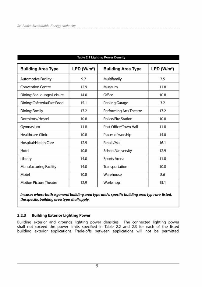
2.2.2 Maximum Allowable Power for Illumination Systems
The lighting power density (LPD) for building lighting systems shall not exceed the values given in Table 2.1. LPD is calculated by dividing the total connected load for all lighting systems in the building by the gross lighted floor area of the building. For building types not listed in Table 2.9 selection of a reasonable equivalent is permitted.
54
Sri Lanka Sustainable Energy Authority
2.2.3 Building Exterior Lighting Power
Building exterior and grounds lighting power densities. The connected lighting power shall not exceed the power limits specified in Table 2.2 and 2.3 for each of the listed building exterior applications. Trade-offs between applications will not be permitted.
Table 2.1 Lighting Power Density
Building Area Type LPD (W/m2) Building Area Type LPD (W/m2)
Automotive Facility 9.7 Multifamily 7.5
Convention Centre 12.9 Museum 11.8
Dining: Bar Lounge/Leisure 14.0 Office 10.8
Dining: Cafeteria/Fast Food 15.1 Parking Garage 3.2
Dining: Family 17.2 Performing Arts Theatre 17.2
Dormitory/Hostel 10.8 Police/Fire Station 10.8
Gymnasium 11.8 Post Office/Town Hall 11.8
Healthcare-Clinic 10.8 Places of worship 14.0
Hospital/Health Care 12.9 Retail /Mall 16.1
Hotel 10.8 School/University 12.9
Library 14.0 Sports Arena 11.8
Manufacturing Facility 14.0 Transportation 10.8
Motel 10.8 Warehouse 8.6
Motion Picture Theatre 12.9 Workshop 15.1
In cases where both a general building area type and a specific building area type are listed, the specific building area type shall apply.
54

Sri Lanka Sustainable Energy Authority
Emergency, Security and Exit Lights
When selecting luminaries to the above usage depends on the requirements specified by the rules and regulations corresponding to the relevant authorities due consideration shall be given to the energy efficient luminaries.
2.3 Prescriptive Requirements2.3.1 General and Task Lighting
Considerations
There may be situations in a lighting installation where the maximum required light level does not need to be maintained
Application Maximum Allowed Power Limits (W/linear m)
Building entrance (with canopy) 32.4 (of canopied area)
Low Traffic (hospital, office, school) 64.8 (of canopied area)
High Traffic (retail, hotel, airport, theatre)
Building entrance (without canopy) 98.4 (of door width)
Building Exit 65.6 (of door width)
Loading
Loading Area 3.0 (W/m2)
Loading Door 50.0 (of door width)
Table 2.2 Maximum Allowed Lighting Power for Building Exteriors
Table 2.3 Table 2.3 Maximum Allowed Lighting Power for Roads/Grounds
Application Maximum Allowed Power Limits (W/m2)
Storage and work area 2.0
Areas for casual use (picnic grounds, gardens, 1.0
parks, scenic landscapes)
Driveways,/walkways
Private 1.0
Public 1.5
Parking lots
Private 1.2
Public 1.8
76

Sri Lanka Sustainable Energy Authority
Table 2.5: Minimum Lamp Efficacy Integral-Type Compact Fluorescent Lamps
Table 2.6: Minimum Lamp Efficacy Modular-Type Compact Fluorescent Lamps
7 54 6
10 57 6
11 78 5
13 66 5
18 63 7
Lamp Power Minimum Lamp Ballast (W) Efficacy (lm/W) Loss
throughout the area. In such situations, the lighting designer may focus on providing ‘Design Maintained Illuminance’ for the task areas while maintaining ‘Standard Maintained Illuminance’ in the surrounding areas. Depending on the concept, this may be achieved by using localised lighting to supplement the general lighting that could be maintained at a minimum.
2.3.2 Selection of Appropriate Components
2.3.2.1 Light Source Selection
The use of incandescent or tungsten halogen lamps for general lighting should be discouraged unless the application specifically requires so. Wherever applicable, general lighting should be provided with fluorescent lamps of appropriate colour.
Although incandescent and tungsten halogen light sources are the least expensive to install, they are less energy efficient compared to sources such as fluorescent lighting or other discharge lamps. (Refer
the Annex 2 for the comparison of lamp efficiencies)
Use of compact fluorescent lamps in ‘downlights’ in ceiling under 4 m and use of high pressure sodium vapour or metal halide lamps for ‘high bay’ applications (ceiling over 4 m) are generally recommended.
2.3.2.2 Lighting Equipment Efficiency Levels
=Fluorescent
It is recommended to use the most efficient, cost effective lamp for each application. The lamp efficacy shall not be lesser than values indicated in Table 2.4 for linear fluorescent lamps and Table 2.5 and 2.6 for compact fluorescent lamps respectively. Note that the lamp efficacy is the efficacy of the lamp alone and it does not include the ballast losses. Lamp efficacy is calculated by dividing the lamp’s rated light output (in lumens) by the rated lamp power (watts). For the system lighting power density (LPD) limits (which include both lamp and ballast) see section 2.2.2.
Table 2.4: Minimum Lamp Efficacy of Linear Fluorescent Lamps (0.6 to 1.2 meters)
Lamp Length Lamp Power Diameter Minimum Lamp (mm) (W) (mm) Efficacy (lm/W)
600 18 26 55
1200 36 26 66
1500 58 26 66
Lamp Power Minimum Lamp (W) Efficacy (lm/W)
09 42
11 52
15 57
20 57
23 62
76

Sri Lanka Sustainable Energy Authority
Fluorescent ballast loss maxima
The ballast losses in linear fluorescent lamp ballasts should not exceed the values given in Table 2.7.
Table 2.7: Maximum Allowed Ballast Losses for Linear Fluorescent Lamp
Ballast Type Maximum Allowed Ballast Loss (W)
Electromagnetic
For 18 W single-lamp 8
For 36 W single-lamp 8
Electronic
For 18 W single-lamp 4
For 18 W double-lamp 6
For 36 W single-lamp 4
For 36 W double-lamp 7
Incandescent
The lamp efficacy for incandescent lamps should not be lesser than the efficacies listed in Table 2.8.
High Intensity Discharge
The lamp efficacy for high intensity discharge lamps (e.g. sodium, metal halide, mercury) should not be lesser than efficacies listed in Table 2.8, and the ballast losses for HID lamps should not exceed the values listed in Table 2.9.
Table 2.8: Incandescent Lamp-Minimum Lamp Efficacy
Lamp Power (W) Minimum Lamp Efficacy (lm/W)
40 10.6
60 12.0
75 12.7
100 13.6
98

Sri Lanka Sustainable Energy Authority
2.3.2.3 Luminaires
Use the most efficient luminaires/ fixtures complying with the manufacturer information of the fixture application. The efficiency of a lighting fixture is given by its light output ratio (LOR) which is defined as the ratio of the lumens from the luminaire to the sum of the individual lumen values of the lamps inside the luminaire. For most fixtures used in commercial buildings, this information is made available through the luminaire/ fixture manufacturers.
For general-purpose lighting systems, use fixtures that have a minimum LOR of at least 0.50. It is never encouraged to use luminaires with LOR below 0.5. Exceptions to this would be a space with critical glare control needs (high-end graphics workstation, for example).
2.3.2.4 Emergency and Exit Lighting
Exit sign luminaire operating at greater than 20 Watts shall have a minimum source efficacy of 35 lumens per Watt. Light Emitting Diodes (LEDs) should be used in exit signs wherever possible.
Emergency lighting includes all of egress
lighting, illuminated exit signs and all other lights specified as necessary to provide the required illumination. Emergency light systems shall be designed and installed so that failure of any individual lighting element, such as the lamp burnout, would not leave any space that requires emergency illumination in total darkness. Switches installed in emergency lighting circuits shall be arranged so that only authorised persons will have control over emergency lighting.
2.4 Strategy for Energy Eefficient Lighting(a) Work out best compromise between
light quantity & quality
(b) Use lamps and ballast with maximum efficiencies
(c) Use of automatic controls such as day light sensors , time based controls or occupancy sensors
(d) Install lighting equipment with high power factor and low harmonic distortion
50 57 10
70 64 15
100 53 15
150 76 20
175 70 22
250 74 26
320 67 28
400 68 30
1000 104 60
1500 98 85
Lamp Power Minimum Lamp Efficacy Maximum Allowed (W) (lm/W) Ballast Loss (W)
Table 2.9: HID Lamp – Minimum Lamp Efficacy & Maximum Allowed Ballast Losses
98
Sri Lanka Sustainable Energy Authority
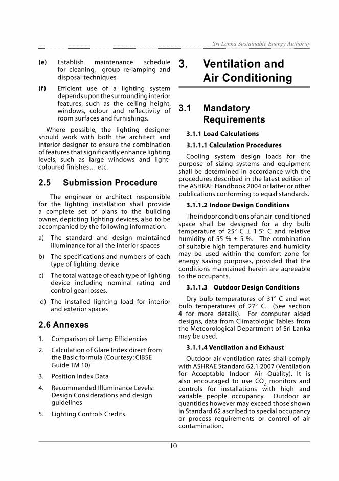
(e) Establish maintenance schedule for cleaning, group re-lamping and disposal techniques
(f ) Efficient use of a lighting system depends upon the surrounding interior features, such as the ceiling height, windows, colour and reflectivity of room surfaces and furnishings.
Where possible, the lighting designer should work with both the architect and interior designer to ensure the combination of features that significantly enhance lighting levels, such as large windows and light- coloured finishes… etc.
2.5 Submission Procedure The engineer or architect responsible
for the lighting installation shall provide a complete set of plans to the building owner, depicting lighting devices, also to be accompanied by the following information.
a) The standard and design maintained illuminance for all the interior spaces
b) The specifications and numbers of each type of lighting device
c) The total wattage of each type of lighting device including nominal rating and control gear losses.
d) The installed lighting load for interior and exterior spaces
2.6 Annexes1. Comparison of Lamp Efficiencies
2. Calculation of Glare Index direct from the Basic formula (Courtesy: CIBSE Guide TM 10)
3. Position Index Data
4. Recommended Illuminance Levels: Design Considerations and design guidelines
5. Lighting Controls Credits.
3. Ventilation and Air Conditioning 3.1 Mandatory Requirements
3.1.1 Load Calculations
3.1.1.1 Calculation Procedures
Cooling system design loads for the purpose of sizing systems and equipment shall be determined in accordance with the procedures described in the latest edition of the ASHRAE Handbook 2004 or latter or other publications conforming to equal standards.
3.1.1.2 Indoor Design Conditions
The indoor conditions of an air-conditioned space shall be designed for a dry bulb temperature of 25° C ± 1.5° C and relative humidity of 55 % ± 5 %. The combination of suitable high temperatures and humidity may be used within the comfort zone for energy saving purposes, provided that the conditions maintained herein are agreeable to the occupants.
3.1.1.3 Outdoor Design Conditions
Dry bulb temperatures of 31° C and wet bulb temperatures of 27° C. (See section 4 for more details). For computer aided designs, data from Climatologic Tables from the Meteorological Department of Sri Lanka may be used.
3.1.1.4 Ventilation and Exhaust
Outdoor air ventilation rates shall comply with ASHRAE Standard 62.1 2007 (Ventilation for Acceptable Indoor Air Quality). It is also encouraged to use CO
2 monitors and
controls for installations with high and variable people occupancy. Outdoor air quantities however may exceed those shown in Standard 62 ascribed to special occupancy or process requirements or control of air contamination.
1110

Sri Lanka Sustainable Energy Authority
3.1.2 System and Equipment Sizing
3.1.2.1 A/C Systems and Equipment
A/C Systems and Equipment shall be sized to provide no more than the space and system loads calculated in accordance with sub-section 3.1.1 above, consistent with available equipment capacity.
3.1.2.2 Multiple Units
Multiple units of the same equipment type, such as multiple chillers, with combined capacities exceeding the design load may be specified to operate concurrently only if controls are provided in sequence, or otherwise, the operation of each unit should be optimally controlled based on the load.
3.1.2.3 Capacity
Capacity of any individual unit shall not be less than 20 kW (output), excepting backup units for specified areas.
3.1.2.4 Pressure Drop
It is recommended that when selecting equipment, the pressure drops in the chilled water cooling coils, water cooled condensers and evaporator coils should be kept below 6 m of water (20 ft of water) total pressure drop across the coil.
3.1.3 Fan System Design Criteria
3.1.3.1 General
The following design criteria apply to all A/C fan systems used for comfort ventilating and/or air conditioning. For the purposes of this sub-section. The energy demand of a fan system is defined as the sum of the demand of all fans operating at designed conditions to supply air from the cooling source to the conditioned space(s) and to the source in return or outdoors as an exhaust.
Exceptions
Systems with total fan system nameplate motor power of 4 kW or less.
3.1.3.2 Constant Volume Fan Systems
For fan systems that provide a constant air
volume whenever the fans are operating, there shall be a requirement of at least 590 l/s of supply air volume per kW of total input power for the motors to provide the combined fan system at design conditions.
3.1.3.3 Variable Air Volume (VAV) Fan Systems
For fan systems that are able to vary system air volume automatically as a function of load, there shall be a requirement of at least 420 l/s of supply air volume per kW of total input power for the motors to provide the combined fan system at designed conditions.
3.1.4 Pumping System Design Criteria
3.1.4.1 General
The following design criteria apply to all pumping systems used for comfort air conditioning. For the purposes of this sub-section, the energy demand of a pumping system is defined as the sum of the demand of all pumps operating at designed conditions to supply fluid from the cooling source to the conditioned space(s) or to heat transfer device(s) and to the source in return.
3.1.4.2 Friction Rate
Piping systems shall be designed at friction pressure loss rate of 100 to 400 Pa per meter of equivalent pipe length subject to the velocity in the system pipe lines not exceeding 2.5 m/s. Lower friction rates may be required for proper noise or corrosion control.
3.1.4.3 Sizing, Selection, and System Design
The following aspects of pumping systems should be designed to minimise life-cycle system costs. Pipe size, components and layout should be optimised to reduce system pressure drops, thus reducing the pump and motor sizes required. Once the operating flow and pressure are established, the pump should be carefully selected for maximum efficiency, and not less than 70 %. The flow rate should never exceed 110 % of designed flow. Once the pump shaft power requirement is determined, the motor with the highest efficiency at the design load
1110

Sri Lanka Sustainable Energy Authority
should be selected to meet or exceed Minimum Motor Efficiency values in Table 5.1. The motor horsepower rating should not exceed 125 % of the calculated maximum load being served.
If a standard rated motor is not available within the range, the next largest standard motor size may be used. It is recommended that pump speeds should be kept less than 1500 rpm. Variable-speed pumps should be considered for variable-flow systems, especially for large systems. Variable-flow chilled water systems should also be evaluated, either as variable flow through the chiller as allowed by many manufacturers; or as primary-secondary pumping systems with constant chiller flow and variable building system flow.
3.1.4.4 Variable Flow
Pumping systems that serve control valves designed to modulate or step open and closed as a function of load, shall be designed for variable fluid flow. Flow may be altered using variable-speed driven pumps, staged multiple pumps, or pumps riding their characteristic curves.
3.1.5 Separate Air Distribution Systems
3.1.5.1 Zones with Non-Simultaneous Operation
Zones that are expected to operate non-simultaneously for more than 300 hours per year shall be served by separate air distribution systems. As an alternative, off-hour controls shall be provided in accordance with Section 3.1.7.3.
3.1.5.2 Zones with Special Process Requirements
Zones with special process temperature and/or humidity requirements shall be served by separate air distribution systems from those serving zones requiring only comfort cooling, or shall include supplementary provisions so that the primary systems may be specifically controlled for comfort purposes only.
Exceptions
Zones requiring comfort cooling only, which are served by a system primarily used
for process temperature and humidity control, need not be served by a separate system if the total supply air to these zones is no more than 25 % of the total system supply air, or the total conditioned floor area of the zones is less than 100 m².
3.1.5.3 Zones with Different Load Characteristics
Separate air distribution systems should be considered for areas of the building having substantially different cooling characteristics, such as perimeter zones in contrast to interior zones.
3.1.6 Temperature Controls
3.1.6.1 System Control
Each A/C system shall include at least one temperature control.
3.1.6.2 Zone Controls
The supply of cooling energy to each zone shall be controlled by individual thermostatic controls responding to temperature within the zone.
In the case of large buildings, the area is broken up in to sections called Zones for purpose of air-conditioning. Normally, each zone is serviced by one AHU and therefore the conditions in each zone needs to be controlled by a thermostat. Each thermostat in operation in turn will control the input of cooling energy (normally by way of chilled water) thereby resulting in effective economic control.
3.1.6.3 Thermostats
Zone controls shall have an inbuilt feature to prevent the setting of the individual zone temperature lower than the indoor designed conditions (24° C). Temperature sensors shall be located in the zone or in the return air path.
The lowest temperature that can be set by a thermostat provided for each zone is limited to the Designed Indoor Temperature (24° C). However, a temperature higher than the designed indoor temperature can be set by the zone thermostat, if necessary, but should not be set below the designed condition..
1312

Sri Lanka Sustainable Energy Authority
3.1.7 Off-Hour Controls
3.1.7.1 Equipment Shutdown During Non-Use
A/C systems shall be equipped with automatic controls capable of accomplishing a reduction of energy use through equipment shutdown, or increase in the temperature set point, during periods of non-use or alternative use of the spaces served by the system. In case of scheduled long term shutdowns of equipment, arrangements must be made to isolate the power supply to the crank case heaters.
Exceptions
(a) Systems serving areas that are expected to operate continuously.
(b) Equipment with a connected load of 2 kW or less may be controlled by readily accessible manual off-hour controls.
3.1.7.2 Outside Air Control During Non-Use
Outdoor air supply and exhaust systems shall be provided with motorised or gravity dampers or other means of automatic volume shutoff or reduction during periods of non-use of alternative use of the spaces served by the system.
Exceptions
(a) Systems serving areas that are expected to operate continuously.
(b) Systems that have a design air flow of 500 l/s or less.
(c) Gravity and other non-electrical ventilation systems may be controlled by readily accessible manual damper controls.
(d) Where temperature limits are restricted by process requirements such as combustion-air intakes.
3.1.7.3 Zones with Non-Simultaneous Operation
Systems that serve zones that can be
expected to operate non-simultaneously for more than 300 hours per year shall include isolation devices and controls to shut off the supply of cooling to each zone independently. For central systems and plants, controls and devices shall be provided to allow stable system and equipment operation for any length of time while serving only the smallest isolation area served by the system or plant. Isolation is not required for zones that are expected to operate continuously.
Isolation areas may be pre-designed for buildings where occupancy patterns are not known at the time of the system design, such as in speculative buildings. Zones may be grouped into a single isolation area provided that the total conditioned floor area does not exceed 250 m² per group nor includes more than one floor.
3.1.8 Piping Insulation
3.1.8.1 Chilled Water Piping
All A/C system chilled water piping shall be thermally insulated in accordance with Table 3.1. This provides not only to reduce heat gain from the outside, but also to avoid condensation on the surface of the installation. The insulation shall be suitably protected from damage and reference is expected to be made to the insulation manufacturer’s catalogue in this regard.
Exceptions
Piping insulation shall not be required in any of the following areas:
(a) Piping that conveys fluids that have a design temperature above 20° C. Note that if the indoor designed conditions are exceeded, insulation may require a higher temperature piping to prevent condensation.
(b) Piping that conveys fluids that have not been heated or cooled through the use of fossil fuels or electricity.
Details of standard piping insulation and methods of calculation are specified in Annex 3.
1312

Sri Lanka Sustainable Energy Authority
3.1.9 Air Handling System Insulation
3.1.9.1 A/C System Ducts and Plenums
All air-handling ducts and plenums installed as part of an AC air distribution system shall be thermally insulated.
Exceptions
Duct insulation is not required in any of the following cases:
(a) Factory installed plenums, casings or ductwork furnished as a part of AC equipment, provided that they are either insulated at the factory or installed in a conditioned space
(b) Exhaust air ducts
(c) Outdoor air ducts
(d) Return air ducts within conditioned space
Details of methods of calculation of thermal resistance are specified in Annex 3.
3.1.10 Air Handling System Ducts
Ductwork and plenums shall be sealed in
accordance with Table 3.2 and with standard industry practice as defined in SMACNA 1995 (Sheet Metal and Air Conditioning Contractors’ National Association, HVAC Duct Construction Standards - Metal & Flexible, 1995).
Plenums shall be avoided in the supply side of the ducting as far as practically possible.
Minimum Design conditions are specified in Annex 3
3.1.11 A/C Equipment
Equipment shall meet or exceed the minimum performance shown in Table 3.4 when tested at the standard rating conditions shown in Table 3.3. Note that except for the cooling towers, the rating conditions are those used internationally (for ease of comparison) rather than being typical of Sri Lankan conditions. VAC designers should determine equipment load profiles and obtain applied part-load values (APLVs) from the manufacturers to better estimate the actual energy use of the equipment as it is used. With the load and APLV information, designers should then select equipment based on minimising life-cycle cost of the system.
Table 3.3: A/C Equipment Standard Rating Conditions (°C)
Leaving chilled water 6.7 6.7 N/A N/A N/A
Entering chilled water 12.2 12.2 N/A N/A N/A
Leaving cooling water 35.0 N/A 35.0 N/A 31.0
Entering cooling water 29.4 N/A 29.4 N/A 36.5
Condenser air inlet N/A 35.0 N/A 35.0 N/A
Evaporator air inlet N/A N/A 27 DB/ 27 DB/
19.5 WB 19.5 WB N/A
Cooling tower air inlet N/A N/A N/A N/A 27.0 WB
Cooling TowersWater-cooled unitary A/C
Air-cooled water chillers
Water-cooled water chillers
Fluid Air-cooled unitary A/C
1514

Sri Lanka Sustainable Energy Authority
a IPLVs and part load rating conditions are only applicable to equipment with capacity modulation.
b Section 12 contains a complete specification of the referenced test procedure, including the referenced year version of the test procedure.
c Single – phase, air - cooled air conditioners < 65,000 Btu/h are regulated by NAECA. SEER values are those set by NAECA
The compressor shall not be controlled by either hot gas bypass or other evaporator pressure regulator control systems unless the system is designed with multiple steps for unloading. The capacity of the hot gas bypass shall be limited to not more than 50 % of the total capacity in systems up to 70 kW of rated capacity, and not more than 25 % of the total capacity in systems over 70 kW of rated capacity.
Water-to-water heat recovery systems (double-bundle chillers) should be used for water heating only after carrying out an energy balance, cost-benefit analysis and life-cycle costing. Systems producing hot water at temperatures exceeding 42° C are discouraged.
3.1.12 Testing, Adjusting, Balancing and Commissioning
Air system balancing shall be accomplished in a manner to minimise throttling losses and fan speeds shall be adjusted to meet designed flow conditions.
Hydronic system balancing shall be accomplished in a manner to minimise throttling losses and the pump impellers shall be trimmed or pump speeds shall be adjusted to meet designed flow conditions.
A/C control systems shall be tested to assure that control elements are calibrated and adjusted and that are in proper working condition.
Systems larger than 350 kW of cooling shall be commissioned in accordance with the procedures in ASHRAE Guideline1-1996, The HVAC Commissioning Process.
3.1.13 Water Treatment
The makeup water for systems larger than 350 kW of cooling shall be analysed by a recognised authority to determine the chemical characteristics of the water. This procedure shall be repeated once in every 365 days from the date of the commissioning of the plant to track changes in chemical characteristics in water if any.
Appropriate water treatment equipment shall be specified and installed to minimise the possibility of corrosion to the water cooling circuits, scale formation, and biological growth as well as the presence of suspended solids and sludge formation. Measures to reduce the quantity of water to be added to the water circuit should also be addressed with the intent to reduce water usage and pumping energy costs.
Water treatment may be in the form of automatically dosing chemicals, magnetic de-scalers, filtration equipment, ozone dosing, or a combination of these methods.
Water treatment shall be in accordance with procedures detailed in ASHRAE 1995 HVAC Applications Handbook, Chapter 44 (Corrosion Control and Water Treatment), or other equivalent publications.
In installations where large air handling units or packaged units are used, arrangements should be made to collect the condensate water to be used as cooling tower makeup water.
3.1.14 Maintenance
(a) An operation and maintenance manual shall be provided to the owner. The manual shall include basic data relating to the operation and maintenance of A/C systems and equipment, as built drawings showing test points, recommended maintenance spares, list of suppliers and their contact details, including but not limited to original copies of manufacturers’ O & M manuals for all pieces of equipment. Required routine maintenance actions shall be clearly identified. Where applicable, A/C controls information such as diagrams, schematics, control sequence descriptions, and maintenance and calibration information shall be included.
1514

Sri Lanka Sustainable Energy AuthorityTa
ble
3.4:
A/C
Equ
ipm
ent M
inim
um P
erfo
rman
ce S
tand
ards
To
com
ply
with
ASH
RAE
stan
dard
90.
1 –
2004
Equi
pmen
t Ty
peSi
ze
Cate
gory
Heat
ing
Sect
ion
Type
Sub-
Cat
egor
y or
Ratin
g Co
nditi
onMi
nim
um
Effic
iency
aTe
st
Proc
edur
e b
Air C
ondit
ioner
s, Ai
r Coo
led
<65,0
00 B
tu/h c
Al
l Sp
lit Sy
stem
10.0
SEER
AR
I
(b
efore
1/23
/2006
) 21
0/240
12
.0 SE
ER
(a
s of 1
/23/20
06)
Si
ngle
Pack
age
9.7 S
EER
(befo
re 1/
23/20
06)
12.0
SEER
(as o
f 1/23
/2006
)
Thro
ugh –
the –W
all,
Air C
ooled
≤3
0,000
Btu/
h c
All
Split
Syste
m 10
.0 SE
ER
(b
efore
1/23
/2006
)
10
.9 S
EER
(as o
f 1/23
/2006
)
12
SEE
R
(a
s of 1
/23/20
10)
Si
ngle
Pack
age
9.7 S
EER
(befo
re 1/
23/20
06)
10.6
SEER
(as o
f 1/23
/2006
)
12
SEE
R
(a
s of 1
/23/20
10)
Small
- Duc
t High
<6
5,000
Btu/
h c
All
Split
Syste
m 10
SEE
R –V
elocit
y, Ai
r Coo
led
Air C
ondit
ioner
s,
≥65,0
00 B
tu/h
and
Elec
tronic
Sp
lit Sy
stem
10
.3 EE
R AR
I Ai
r Coo
led
<135
,000 B
tu/h
Resis
tance
an
d Sing
le Pa
ckag
e
340/3
60
( or N
one)
Al
l othe
r Sp
lit Sy
stem
and
10.1
EER
Si
ngle
Pack
age
≥1
35,00
0 Btu/
h an
d El
ectro
nic
<240
,000 B
tu/h
Resis
tance
Sp
lit Sy
stem
and
9.7 E
ER
( o
r Non
e)
Sing
le Pa
ckag
e
All o
ther
Split
Syste
m an
d 9.5
EER
Sing
le Pa
ckag
e
≥240
,000 B
tu/h
and
Elec
tronic
Sp
lit Sy
stem
and
9.5 E
ER
<760
,000 B
tu/h
Resis
tance
Si
ngle
Pack
age
9.7 IP
LV
( o
r Non
e)
All o
ther
Split
Syste
m an
d 9.3
EER
Si
ngle
Pack
age
9.5 IP
LV
≥7
60,00
0 Btu/
h
Elec
tronic
Re
sistan
ce
Split
Syste
m an
d
( o
r Non
e)
Sing
le Pa
ckag
e 9.2
EER
9.4 IP
LV
All o
ther
Split
Syste
m an
d 9.0
EER
Si
ngle
Pack
age
9.2 IP
LV
1716

Sri Lanka Sustainable Energy Authority
Air C
ondit
ioner
s, Ai
r Coo
led
<65,0
00 B
tu/h c
Al
l Sp
lit Sy
stem
10.0
SEER
AR
I
(b
efore
1/23
/2006
) 21
0/240
12
.0 SE
ER
(a
s of 1
/23/20
06)
Si
ngle
Pack
age
9.7 S
EER
(befo
re 1/
23/20
06)
12.0
SEER
(as o
f 1/23
/2006
)
Thro
ugh –
the –W
all,
Air C
ooled
≤3
0,000
Btu/
h c
All
Split
Syste
m 10
.0 SE
ER
(b
efore
1/23
/2006
)
10
.9 S
EER
(as o
f 1/23
/2006
)
12
SEE
R
(a
s of 1
/23/20
10)
Si
ngle
Pack
age
9.7 S
EER
(befo
re 1/
23/20
06)
10.6
SEER
(as o
f 1/23
/2006
)
12
SEE
R
(a
s of 1
/23/20
10)
Small
- Duc
t High
<6
5,000
Btu/
h c
All
Split
Syste
m 10
SEE
R –V
elocit
y, Ai
r Coo
led
Air C
ondit
ioner
s,
≥65,0
00 B
tu/h
and
Elec
tronic
Sp
lit Sy
stem
10
.3 EE
R AR
I Ai
r Coo
led
<135
,000 B
tu/h
Resis
tance
an
d Sing
le Pa
ckag
e
340/3
60
( or N
one)
Al
l othe
r Sp
lit Sy
stem
and
10.1
EER
Si
ngle
Pack
age
≥1
35,00
0 Btu/
h an
d El
ectro
nic
<240
,000 B
tu/h
Resis
tance
Sp
lit Sy
stem
and
9.7 E
ER
( o
r Non
e)
Sing
le Pa
ckag
e
All o
ther
Split
Syste
m an
d 9.5
EER
Sing
le Pa
ckag
e
≥240
,000 B
tu/h
and
Elec
tronic
Sp
lit Sy
stem
and
9.5 E
ER
<760
,000 B
tu/h
Resis
tance
Si
ngle
Pack
age
9.7 IP
LV
( o
r Non
e)
All o
ther
Split
Syste
m an
d 9.3
EER
Si
ngle
Pack
age
9.5 IP
LV
≥7
60,00
0 Btu/
h
Elec
tronic
Re
sistan
ce
Split
Syste
m an
d
( o
r Non
e)
Sing
le Pa
ckag
e 9.2
EER
9.4 IP
LV
All o
ther
Split
Syste
m an
d 9.0
EER
Si
ngle
Pack
age
9.2 IP
LV
1716

Sri Lanka Sustainable Energy AuthorityEq
uipm
ent
Type
Size
Ca
tego
ryHe
atin
g Se
ctio
n Ty
peSu
b- C
ateg
ory o
r Ra
ting
Cond
ition
Mini
mum
Ef
ficien
cya
Test
Pr
oced
ure b
Air C
ondit
ioner
s,
<65,0
00 B
tu/h c
Al
l othe
r Sp
lit Sy
stem
12
.1 EE
R AR
I 210
/240
an
d Wate
r and
Si
ngle
Pack
age
Evap
orati
vely
Coole
d
≥65,0
00 B
tu/h
and
Elec
tronic
Sp
lit Sy
stem
and
11.5
EER
ARI
<1
35,00
0 Btu/
h Re
sistan
ce
Sing
le Pa
ckag
e
340/3
60
( or N
one)
Al
l othe
r Sp
lit Sy
stem
and
11.3
EER
Si
ngle
Pack
age
≥1
35,00
0 Btu/
h an
d El
ectro
nic
Split
Syste
m 11
.0 EE
R
<240
,000 B
tu/h
Resis
tance
an
d Sing
le Pa
ckag
e
( o
r Non
e)
Al
l othe
r Sp
lit Sy
stem
10
.8 EE
R
and S
ingle
Pack
age
≥2
40,00
0 Btu/
h
Elec
tronic
Sp
lit Sy
stem
and
11.0
EER
Resis
tance
Si
ngle
Pack
age
10.3
IPLV
( or N
one)
All o
ther
Split
Syste
m an
d 10
.8 EE
R
Sing
le Pa
ckag
e 10
.1 IP
LV
Cond
ensin
g Unit
s,
≥135
,000 B
tu/h
-
10
.1 EE
R AR
I 365
Air C
ooled
11.2
IPLV
Cond
ensin
g Unit
s, ≥1
35,00
0 Btu/
h
13
.1 EE
R W
ater a
nd
13
.1 IP
LV
-
Evap
orati
vely
Co
oled
1918

Sri Lanka Sustainable Energy Authority
(b) The owner should implement a preventive maintenance program and schedule periodic maintenance on all the critical items of the air-conditioning system such as compressors, cooling towers, pumps, condensers, air handlers, controls, filters and piping.
Owner shall appoint a responsible officer to be in charge of the equipment to make sure that the equipment and the system are operated as efficiently as possible. Key control parameters of the system must be periodically compared against the commissioning data to ensure that the system is operating at or near designed conditions.
Arrangements shall be made to ensure that the above mentioned maintenance procedures are followed diligently.
3.1.15 Submission Procedure
Plans on refrigeration and air-conditioning, prepared by an experienced Chartered Mechanical Engineer, will be provided to the Building Owner, containing the following information.
(a) The cooling capacity in kW of each air-handling unit and air-conditioning plant
(b) The capacity in l/s of each fan
(c) The location and capacity of each fresh air intake
(d) Supply, exhaust and return duct work distinctly coloured for clarity
(e) A summary of the air-conditioning load calculations and equipment performance figures
3.2 Annexes1. Piping insulation equations and
standard values
2. Air handling system insulation equations
3. Air handling system ducting design considerations
4. Comfort Zone Diagram
4. Building Envelope
Building Envelope element of an occupied building facility contributes to a substantial share of the cooling or heating load. The Heating, Ventilating and Air-conditioning (HVAC) system has to cater to this load as well in order to maintain the comfort and/or process conditions. Thus, the Building Envelop element plays an important role with respect to energy consumed and cost of energy in its operating phase during the entire life of the building facility.
4.1 General Principles of Energy Efficient Envelope Design
4.1.1 Pre-Considerations
Minimising the solar gain through the building envelope happens to be a primary consideration within the Sri Lankan context. Hence, siting and orientation of the building with its long axis in line with east-west, avoiding openings facing east and west directions, especially the west, use of light coloured walls & roof surfaces, appropriate internal & external shading for fenestration, moderate window to wall ratios, minimum air infiltration into the occupied space and economic utilisation of building envelope insulation are recommended pre-considerations at the design stage.
4.1.2 Consideration of Climatic Zones and Building Typology
a. Climatic Zones – 03 Climatic zones shall be considered: The outdoor design condition would vary based on the corresponding climatic zone. This will in turn dictate the thermo-physical properties of all building elements.
i) warm-humid - (DBT, WBT) (310 oC, 270 oC)
ii) warm-dry - (DBT, WBT) (330 oC, 260 oC)
iii) uplands - (DBT, WBT) (280 oC ,230 oC)
b. Building Typology – 02 types of building categories are considered based on duration of operation.
1918

Sri Lanka Sustainable Energy Authority
i) Day-Time operation (Offices, Shops, etc.)
ii) Extended operation (Hotels, Hospitals, Condominiums, Supermarkets, etc.)
4.1.3 Method of Compliance
This will be achieved by meeting the overall requirement – the Overall Thermal Transfer Value (OTTV) – subject to satisfying prescriptive criteria of each building envelope sub-element descried ahead.
4.2 Mandatory Requirements4.2.1 U-values
U-values for roofs, fenestrations and facades (for determining the corresponding OTTVi values) shall be determined from property data provided in Appendix 4.
4.2.2 Envelope Sealing
The following areas of the building envelope shall be sealed, caulked, gasketed or weather-stripped to minimise air leakage for buildings whose occupancy areas are treated other than by natural or any mechanical means of ventilation:
a) Joints around fenestration and doors
b) Junctions between walls and foundations, between walls & building corners, between walls and structural floors and roofs and between roof or wall panels
c) Openings at penetrations of utility services through roofs, walls and floors
d) Site built fenestrations and doors
e) Building assemblies used as ducts or plenums
f ) Joints, seams and penetrations of vapour retarders
g) All other openings in the building envelope
4.2.3 Air Leakage
Fenestration and doors shall be designed to limit air leakage such that the air infiltration does not exceed 5 l/s m2 for glazed swinging entrance doors and for revolving doors and 2 l/s m2 for all other fenestration and doors.
4.2.4 National Building Regulations
Any existing national building regulations for minimum natural ventilation and daylight harnessing shall be complied with.
4.3 Prescriptive Requirements4.3.1 External Wall with/without
Fenestration (Facades)
a) Visual Light Transmittance (VLT) The Mean Visual Light Transmittance (VLT) for all fenestrations shall be greater than 0.15
b) OTTVi values for Facades
Note:
i) OTTV for each of the distinct façades of the building (OTTVi) shall be estimated in accordance with the formula given in the Appendix 4a.
ii) U-factors for opaque walls shall be estimated using Thermal Properties from Appendix 4b.
iii) Solar correction factor (CF) for fenestrations shall be selected from Appendix 4c.
iv) Combined Shading Coefficient (SC) for fenestrations shall be selected from Appendix 4d.
4.3.2 Roofs
a) Exterior roof surface solar absorptivity for non-tiled roofing surfaces shall be less than 0.4.
b) U-Factor for roofs
Table 4.3.1a: Maximum U-values for facades (External walls with/without Fenestration)
Day-Time Extended operation operation (Wm-2K-1) (Wm-2K-1)
Warm-humid 0.45 0.40Warm-dry 0.45 0.40Upland 0.38 0.35
2120

Sri Lanka Sustainable Energy Authority
4.3.3 Windows
Heat gain through windows could be controlled and reduced in many ways.
Strategies include the control of:
a) Window area, expressed as window-to-wall ratio (WWR).
b) Glass type, expressed as the shading coefficient for the glass (SCg).
c) Use of internal shading devices (SCint) and external shading devices (SCext) (external sunscreens, overhangs, fins, venetian blinds).
4.4. Compliancei) All above stated Mandatory requirements
shall be met
ii) Area weighted cumulative OTTV of the Actual building design combining actual OTTVi values of all facades of the building and U-factor values of roofs (hence the OTTVroof ) shall be less than the corresponding cumulative OTTV of the Actual building design estimated using all prescriptive values and also than a value of 50 W/m2.
4.5 Submission procedurei) OTTV & U-value estimations for facades
& roofs shall be done using the VB-XL environment based code provided with the BEC or any other suitable substitute.
ii) Relevant data, accompanied by drawings shall be provided by the client with authorised manufacturers’ specifications wherever applicable.
iii) Data on air leakage shall be provided by the client with supportive evidence
4.6 Annexes1. OTTV formula
2. Solar Correction Factor for Fenestrations (CF)
3. Combined Shading Coefficients (SC)
Note:
OTTV for the roof of the building (OTTVroof ) shall be estimated in accordance with the formula given in the Appendix 4a using WWR=0.
Table 4.3.2a: Maximum U-Factor values for Roofs.
Day-Time operation (Wm-2K-1) Extended operation (Wm-2K-1)
Tiled Non-Tiled Tiled Non-Tiled
Warm-humid 0.30 0.40 0.30 0.28
Warm-dry 0.25 0.40 0.25 0.28
Upland 0.20 0.35 0.20 0.25
2120

Sri Lanka Sustainable Energy Authority
5. Electric Power and Distribution
5.1 General Principles of Energy Efficient Electrical Power Distribution
5.1.1 This section applies to all building electrical systems, except extra low voltage systems, if wired separately.
5.1.2 The following sub-sections address only energy-efficiency issues and not other aspects of design, installation, operation, and maintenance of building electrical power and distribution systems.
5.1.3 For existing buildings at the stage of rewiring, all criteria under 5.2.1 shall apply.
5.1.4. No part of this section shall be construed as encouraging energy efficiency at the expense of safety and performance. The CODE shall in no way supersede electrical safety requirements in Section 60 (2) (e) 5 detailed in the Subsidiary Legislation under the Electricity Act.
5.2 Mandatory requirements5.2.1 Electrical Distribution System
5.2.1.1 Supply connection exceeding 1000 kVA shall have a built-in recording facility to record demand (kVA), energy consumption (kWh), and total power factor in permanently installed energy meters. The metering shall also display current (Amperes in each phase and the neutral), voltage (Voltage between phases and between each phase and neutral), and percentage total harmonic distortion (THD of current).
5.2.1.2 Supply connections not exceeding 1000 kVA but over125 kVA shall have a built-in recording facility to record demand (kVA), energy consumption (kWh), and total power factor.
5.2.1.3 Supply connections not exceeding 125 kVA shall have a built-in recording facility to record energy consumption (kWh).
5.2.1.4 Check Metering. Buildings, where the
maximum demand is greater than 250 kVA, shall have the electrical distribution system designed so that energy consumption can be check-metered. The electrical power feeder for each facility for which check-metering is required shall be subdivided in accordance with the following categories.
(a) Lighting and socket outlets
(b) Air-conditioning systems and equipment
(c) Other load centres with high probable energy consumption, such as kitchen, laundry, and restaurants in hotels, or surgery rooms in hospitals
5.2.1.5 Divisional/Tenant sub-metering. A building occupied by many divisions of the same organisation or Multiple Tenant Buildings shall have sub-metering for each tenant. Each tenant having a maximum demand of 100 kVA or more shall have provision to permit check-metering the tenant load as per 5.2.1.4 above. Common air-conditioning systems need not meet these tenant check-metering requirements.
5.2.1.6 Power Factor Correction. All electricity supplies exceeding 100A, 3 phase shall maintain their power factor between 0.98 lag and unity at the point of connection. Loads should have power factor correction at the point of use (capacitors on motors and lighting fixtures with ballasts; harmonic filters on non-linear loads); if necessary further correction equipment at the main switchboard should be provided to meet the overall requirement.
5.2.1.7 Neutral Current. Building loads should be balanced such that the fundamental component of the neutral current in any three-phase installation does not exceed 10 % of the design current of the entire installation when the design current is being drawn.
5.2.1.8 Conductor Sizing. Designers should have documentary evidence to demonstrate how, subject to safety and performance constraints, electrical conductors have been selected in a manner that minimises life-cycle costs.
5.2.1.9 Energy Audit, Prior to energizing the electrical installation, a pro-forma energy
2322

Sri Lanka Sustainable Energy Authority
audit should be carried out encompassing all LV energy consuming equipment and the associated network to ensure that the design of the entire electrical system has been optimised in a cost-effective manner.
5.2.2 Transformers
5.2.2.1 All transformers that are part of the building electrical distribution system should be selected to minimise the combination of no-load, part-load, and full-load losses, without compromising the electrical system operation and reliability requirements.
5.2.2.2 If the total capacity of such transformers exceeds 250 kVA, a calculation of total estimated annual operating costs of the transformer losses shall be made and compared
to the cost of more efficient transformers. This calculation shall be based on estimated hours of transformer operation at projected loading conditions and the associated transformer losses. Based on this analysis, transformer(s) with the lowest life-cycle cost shall be selected.
5.2.3 Electric Motors
All permanently wired electric motors that serve the building shall meet the requirements of this section.
5.2.3.1 Three-phase induction motors shall have a nominal full-load motor efficiency not less than shown as “Required” in Table 5.1.
5.2.3.2 Efficiencies of motor types and sizes not covered in Table 5.1 are not regulated by this section. However, designers should use
Table 5.1: Minimum Efficiencies for Three-Phase Induction Motors
Motor Output Required Efficiency (%) Recommended Efficiency (%)
(kW) 2 pole 4 pole 2 pole 4 pole
1.1 82.2 83.8 85.5 86.5
1.5 84.1 85.0 86.5 86.5
2.2 85.6 86.4 86.5 89.5
3.0 86.7 87.4 87.2 89.5
4.0 87.6 88.3 89.5 89.5
5.5 88.5 89.2 89.5 91.0
7.5 89.5 90.1 90.2 91.7
11.0 90.6 91.0 91.0 93.0
15.0 91.3 91.8 92.4 93.0
18.5 91.8 92.2 93.0 93.6
22.0 92.2 92.6 93.0 94.1
30.0 92.9 93.2 93.6 94.1
37.0 93.3 93.6 93.6 94.5
45.0 93.7 93.9 94.1 95.0
55.0 94.0 94.2 94.5 95.0
75.0 94.6 94.7 95.0 95.4
Reference Conditions: Nominal full-load efficiencies per IEC 34 – 2 test procedure.
2322

Sri Lanka Sustainable Energy Authority
highly efficient motors for other categories not specifically covered by this standard. Such categories include smaller and larger poly-phase motors, poly- phase motors of 6 and 8 poles, and single phase motors.
5.2.3.3 Motor nameplates shall list the minimum and the nominal full-load motor efficiencies and the full-load power factor.
5.2.3.4 Motor horsepower rating shall not exceed 200 % of the calculated maximum load being served.
5.2.3.5 Motor uses should insist on proper rewinding practices for any rewound motors. If such practices cannot be assured, the damaged motor should be replaced with a new efficient one rather than suffer the significant efficiency penalty associated with typical rewinding practices. A list of practices to be followed at a minimum is given in Annex 5.
5.3 Prescriptive Requirements5.3.1 Additional Metering. The designer and
user should consider additional metering where it would be useful for analysis to improve efficiency in the end-use loads and the distribution systems serving them. The outputs of such metering could be beamed wirelessly to a location such as the one occupied by the officer designated by the organisation to optimise energy usage, so that the rate of energy consumption (should be displayed in monetary terms where the meter is programmable) and its variations are constantly visible to this officer. It is also preferable to design
additional internal metering for sub sections of energy consumption such as lighting, air conditioning etc.
5.3.2 System designers should select motors to minimise the life-cycle cost of the motor-driven system. Such analysis will often result in the use of motors of a higher efficiency than required herein. The “Recommended” efficiencies in Table 5.1 provide a suggested improved efficiency level for motor selection. Designers should perform a life-cycle cost analysis to select the proper motor.
5.4 Design Considerations5.4.1 Three-phase oil-immersed transformers
shall be selected based on maximum allowable losses in Tables 5.2 and 5.3.
Exceptions
(a) Transformers below 100 kVA and above 1000 kVA
(b) AC and DC drive transformers
(c) All rectifier transformers and transformers designed for higher harmonics
(d) Autotransformers
(e) Non-distribution transformers, such as UPS (Uninterruptible Power Supply) transformers
(f) Special impedance transformers applied for special cases
(g) Grounding or testing transformers
Transformer Maximum Allowable Losses at Full Load Capacity (kVA) (% Load Loss + No–Load Loss)
100 2.5 160 2.3 250 2.1 400 1.5 630 1.4 800 1.4 1000 1.2
Reference conditions: 100 % of nameplate load at a temperature of 750 C.
Table 5.2: 11kV Transformer, 3 phase, oil immersed
2524

Sri Lanka Sustainable Energy Authority
5.5 Submission Procedure Building owners shall be provided in
writing basic data relating to the design, operation and maintenance of the electrical distribution system of the building. This shall include:
(a) A single-line diagram of the building electrical system, inclusive of all the metering equipment.
(b) Floor plans showing locations of equipment, distribution gear, power factor correction equipment and the metering equipment.
(c) Schematic diagrams of electrical control systems used for power saving (if any).
(d) Manufacturers’ data sheets confirming the maximum losses, allowed for transformers by clause 5.4.1 (applicable only for consumer owned transformers) and allowed for motors by clause 5.2.3.1.
5.6 Annexes 1. Guidelines for Maintaining Motor
Efficiency During Rebuilding
Table 5.3: 33kV Transformer, 3 phase, oil immersed
Transformer Maximum Allowable Losses at Full Load Capacity (kVA) (% Load Loss + No–Load Loss) 100 2.7 160 2.2 250 1.8 400 1.5 630 1.5 800 1.5 1000 1.2
Reference conditions: 100 % of nameplate load at a temperature of 750 C.
6. Service Water Heating
6.1 General Principles6.1.1 This section applies to all service water
heating systems and equipment.
6.1.2 The following sub-sections address only energy-efficiency issues and not other aspects of design, installation, operation and maintenance of service water heating systems.
6.1.3 The energy usage in these buildings can be significantly reduced if the following conservation measures are adopted.
a) Metering of hot water usage
b) Metering of hot water temperature
c) Controlling hot water flow rate
d) Maintaining hot water generating and storing facilities
e) Insulate and maintain the insulation of all hot water storage, tanks and circulating pipelines
6.1.4 These requirements apply to equipment used to produce and distribute hot water for:
a) Restrooms
b) Showers
2524

Sri Lanka Sustainable Energy Authority
c) Laundries
d) Pools and spas
e) Car washes, beauty salons and other commercial enterprises
f) hotels
6.2 Sizing of Systems 6.2.1 Service water heating system design
loads for the purpose of sizing systems and equipment shall follow manufacturers’ recommendations.
6.2.2 Design Considerations
a) Minimise standby losses with heat traps, thermal insulation and temperature controls.
b) Reduce distribution losses with thermal insulation and system temperature controls or eliminate through point-of-use heaters.
c) Reduce hot water waste with flow-limiting or metering terminal devices.
d) Increase overall system performance with high efficiency sources.
6.3 Mandatory requirements6.3.1 Water Heating Equipment Efficiency
6.3.1.1 All water heating equipment, hot water supply boilers used solely for heating potable water, pool heaters and hot water storage tanks shall meet criteria listing in Table 6.1.
6.3.1.2 Electric resistance water heaters are strongly discouraged except as backup for other SHW systems. Electric heat pump water heaters have considerably higher energy efficiency than electric resistance water heaters, particularly within the local climatic context.
6.3.1.3 Efficiency for electric resistance water heaters is given in terms of maximum Standby Loss (SL), where V is the measured volume in litres. SL is the maximum watts based on a 38.9° C temperature difference between stored water and ambient requirements.
6.3.1.4 Minimum efficiency for oil & gas-fired water heaters is given in terms of Thermal Efficiency (ET), which includes thermal losses from the heater shell.
6.3.1.5 Solar water heaters shall have a minimum efficiency of 60 % and have at least R-2.2 insulation behind the collector plate.
6.3.2 Service Water Heating Piping Insulation
6.3.2.1 Entire hot water systems including storage tanks, pipelines shall be insulated properly to minimise the heat losses. The following hot water piping shall be insulated to levels specified in Section 6.4.2
(a) Recirculating system piping, including the supply and return piping of a circulating tank type water heater
b) The first 2.4 meters of outlet piping for a constant temperature non-recirculating storage system
(c) The inlet pipe between the storage tank and a heat trap in a non-recirculating storage system
(d) Pipes that are externally heated
6.3.2.2 Piping for heating systems with a design operating temperature of 60o C or greater
Table 6.1: Minimum Energy Efficiencyof Water Heating Equipment
Equipment Type Minimum EfficiencyElectric Resistance 5.9 + 5.3V SL (W) Water Heaters Gas Storage 78% ET Water Heaters Gas Instantaneous 78% ET Water Heaters Gas Hot Water 77% ET Supply Boilers Oil Hot Water 80%ET Supply Boilers Dual Fuel Gas/Oil Hot 80% ETWater Supply Boilers
2726

Sri Lanka Sustainable Energy Authority
shall have at least R-0.70 insulation. Piping for heating systems with a design operating temperature of less than 60o C but greater than 40o C shall have at least R-0.35 insulation.
6.3.2.3 Insulations exposed to weather shall be protected by aluminum sheet metal, painted canvas, plastic cover, or similar materials.
6.3.3 Service Water Heating System Controls
6.3.3.1 Temperature controls shall be provided to limit the maximum temperature of water delivered to wash basin faucets in public restrooms to 43° C.
6.3.3.2 Sanitary codes or nationally adopted standards define the conditions of the hot water required for each application under consideration.
6.3.3.3 Systems designed to maintain usage temperatures in hot water pipes, such as recirculating hot water systems, shall be equipped with automatic time switches or other controls that can be set to switch off the usage temperature maintenance system during extended periods when hot water is not required.
6.3.3.4 Recirculating pumps shall be equipped with controls limiting operation to a period, staring from the beginning of the heating cycle to a maximum of 5 minutes following the end of the cycle, in maintaining storage tank water temperatures.
6.4 Prescriptive Requirements6.4.1 Temperature Limits
6.4.1.1 Temperature controls shall be provided to limit point-of-use water temperatures not exceeding 50° C.
6.4.2 Heat Traps
Vertical pipe risers serving storage water heaters and storage tanks not having integral heat traps and serving a non-recirculating system shall have heat traps on both the inlet and outlet piping as close as possible to the storage tank. A heat trap is a means to counteract the natural
convection of heated water in a vertical pipe run, by either a device specifically designed for the purpose or an arrangement of tubing that forms a loop of 360 degrees, or piping that from the point of connection to the water heater (inlet or outlet) includes a length of piping directed downward before being connected to the vertical piping of the supply water or hot water distribution system, as applicable.
6.5 Design Considerations6.5.1 Supplementary Service Water Heating
Systems
Where appropriate, supplementary service water heating system should be designed to maximise the energy efficiency of the system, incorporating the following:
(a) Solar water heating systems to supply all or part of service water demand.
(b) Heat recovery from hot discharge systems
(c) Use of alternative fuels such as LPG
(d) Electric heaters as last resort.
6.6 Submission Procedure The Engineer responsible for the service hot
water system installation shall provide complete details to the Building Owner inclusive of the following information.
(a) Input energy consumption rate (kW/kcal)
(b) Design operating temperature range
(c) For boilers, maximum design pressure, tested pressure (Pa)
(d) Type of fuel used
(e) Listing of equipment
(f) Storage tank capacity
(g) Maximum draw-off rate (l/s)
6.7 AnnexesMinimum Pipe Insulation Thicknesses for Service Hot Water Systems
2726
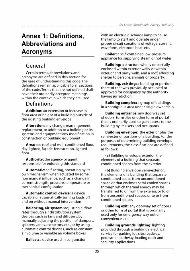
Sri Lanka Sustainable Energy Authority
Annex 1: Definitions, Abbreviations and Acronyms
GeneralCertain terms, abbreviations, and
acronyms are defined in this section for the ease of understanding this code. The definitions remain applicable to all sections of the code. Terms that are not defined shall have their ordinarily accepted meanings within the context in which they are used.
DefinitionsAddition: an extension or increase in
floor area or height of a building outside of the existing building envelope
Alteration: any change, rearrangement, replacement, or addition to a building or its systems and equipment; any modification in construction or building equipment
Area: see roof and wall, conditioned floor, day-lighted, façade, fenestration, lighted floor
Authority: the agency or agent responsible for enforcing this standard
Automatic: self-acting, operating by its own mechanism when actuated by some non manual influence, such as a change in current strength, pressure, temperature or mechanical configuration.
Automatic control device: a device capable of automatically turning loads off and on without manual intervention
Balancing, air system: adjusting airflow rates through air distribution system devices, such as fans and diffusers, by manually adjusting the position of dampers, splitters vanes, extractors, etc., or by using automatic control devices, such as constant air volume or variable air volume boxes
Ballast: a device used in conjunction
with an electric-discharge lamp to cause the lamp to start and operate under proper circuit conations of voltage, current, waveform, electrode heat, etc.
Boiler: a self-contained low-pressure appliance for supplying steam or hot water
Building: a structure wholly or partially enclosed within exterior walls, or within exterior and party walls, and a roof, affording shelter to persons, animals or property.
Building, existing: a building or portion there-of that was previously occupied or approved for occupancy by the authority having jurisdiction
Building complex: a group of buildings in a contiguous area under single ownership
Building entrance: any doorway set of doors, turnstiles or other form of portal that is ordinarily used to gain access to the building by its users and occupants
Building envelope: the exterior plus the semi-exterior portions of a building. For the purposes of determining building envelope requirements, the classifications are defined as follows:
(a) Building envelope, exterior: the elements of a building that separate conditioned spaces from the exterior
(b) Building envelope, semi-exterior: the elements of a building that separate conditioned space from unconditioned space or that encloses semi-cooled spaces through which thermal energy may be transferred to or from the exterior, or to or from unconditioned spaces, or to or from conditioned spaces
Building exit: any doorway set of doors, or other form of portal that is ordinarily used only for emergency way out or convenience exit
Building grounds lighting: lighting provided through a building’s electrical service for parking lot, site, roadway, pedestrian pathway, loading dock and security applications
2928

Sri Lanka Sustainable Energy Authority
Building material: any element of the building envelope through which heat flows and that heat is included in the component U-factor calculations other than air films and insulation
Circuit breaker: a device designed to open and close a circuit by non-automatic means and to open the circuit automatically at a predetermined over-current without damage to itself when properly applied within its rating
Coefficient of Performance (COP) – cooling: the ratio of the rate of heat removal to the rate of energy input, in consistent units, for a complete refrigerating system or some specific portion of that system under designated operating conditions
Commercial building: all buildings except for multi-family buildings of three stories or fewer above grade and single-family buildings
Conditioned space: a cooled space, heated space, or indirectly conditioned space.
Construction documents: drawings and specifications used to construct a building, building systems, or portions thereof
Control: to regulate the operation of equipment
Control device: a specialized device used to regulate the operation of equipment
Day-lighted area: the daylight illuminated floor area under horizontal fenestration (skylight) or adjacent to vertical fenestration (window)
Demand: the highest amount of power (average kVA over an interval) recorded for a building or facility in a selected time frame
Design capacity: output capacity of a system or piece of equipment at design conditions
Design conditions: specified environmental conditions, such as temperature and light intensity required to be produced and maintained by a system
and under which the system must operate
Distribution system: a device or group of devices or other means by which the conductors of a circuit can be disconnected from their source of supply
Door: all operable opening areas (which are not fenestration) in the building envelope, including swinging and roll-up doors, fire doors, and access hatches. Doors that are more than one-half glass are considered fenestration. For the purposes of determining building envelope requirements, the classifications are defined as follows:
(a) Door, non-swinging: roll-up sliding, and all other doors that are not swinging doors.
(b) Door, swinging: all operable opaque panels with hinges on one side and opaque revolving doors.
Effective aperture, horizontal fenestration: a measure of the amount of daylight that enters a space through horizontal fenestration (skylights). It is the ratio of the skylight area times the visible light transmission divided by the gross roof area above the day-lighted area.
Efficacy: the lumens produced by a lamp/ballast system divided by the total watts of input power (including the ballast), expressed in lumens per watt
Efficiency: performance at a specified rating condition
Remittance: the ratio of the radiant heat flux emitted by a specimen to that emitted by a blackbody at the same temperature and under the same conditions
Enclosed building: a building that is totally enclosed by walls, floors, roofs, and openable devices such as doors and operable windows
Energy: the capacity for doing work. It takes a number of forms that may be transformed from one into another such as thermal (heat), mechanical (work), electrical
2928
Sri Lanka Sustainable Energy Authority
and chemical. Customary measurements are watts (W)
Energy Efficiency Ratio (EER): the ratio of net cooling capacity in Btu/h to total rate of electric input in watts under designated operating conditions
Energy Factor (EF): a measure of water heater overall efficiency
Equipment: devices for comfort conditioned, electric power, lighting, transportation or service water heating including, but not limited to furnaces, boilers, air conditioners, heat pumps, chillers, water heaters, lamps, luminaries, ballasts, elevators, escalators or other devices or installations
Equipment, existing: equipment previously installed in an existing building
Facade area: area of the facade, including overhanging soffits, cornices, and protruding columns, measured in elevation in a vertical plane, parallel to the plane of the face of the building. Non-horizontal roof surfaces shall be included in the calculations of vertical facade area by measuring the area in a plane parallel to the surface.
Fan system power: the sum of the nominal power demand (nameplate W or HP) of motors of all fans that are required to operate at design conditions to supply air from the heating or cooling source to the conditioned space(s) and return it to the source of exhaust it to the outdoors.
Fenestration: all areas (including the frames) in the building envelope that let in light, including windows, plastic panels, clerestories, skylights, glass doors that are more than one-half glass, and glass block walls.
(a) Skylight: a fenestration surface having a slope of less than 60 degrees from the horizontal plane. Other fenestration, even if mounted on the roof of a building, is considered vertical fenestration.
Fenestration area: the total area of fenestration measured using the rough
opening and including the glass or plastic, sash, and frame.
Heat: the form of energy that is transferred by virtue of a temperature difference or a change in state of a material.
Illuminance: the density of the luminous flux incident on a surface. It is the quotient of the luminous flux multiplied by the area of the surface when the latter is uniformly illuminated.
Infiltration: the uncontrolled inward air leakage through cracks and crevices in any building element and around windows and doors of a building.
Joule (J): is the work done or the energy expended when a force of one Newton moves the point of application a distance of one metre in the direction of that force.
Kelvin (K): the unit of thermodynamic temperature. It is 1/273.16 of the thermodynamic temperature of the triple point of water.
Kilogram (kg): the unit of mass.
Kilovolt-ampere (kVA): where the term “kilovolt-ampere” (kVA) is used in this standard, it is the product of the line current (amperes) times the nominal system voltage (kilovolts) times 1.732 for three-phase currents. For single-phase applications, kVA is the product of the line current (amperes) times the nominal system voltage (kilovolts).
Kilowatt (kW): the basic unit of electric power, equal to 1000 W.
Lamp: a generic term for man-made light source often called bulb or tube.
Large scale housing developments: structured building development of residential properties. Earlier popular throughout the US & UK, these areas of high population density.
Lighted floor area, gross: the gross floor area of lighted spaces.
Lighting, decorative: lighting that is purely ornamental and installed for
3130
Sri Lanka Sustainable Energy Authority
aesthetic effect. Decorative lighting shall not include general lighting.
Lighting, emergency: lighting that provides illumination only when there is a general lighting failure.
Lighting, general: lighting that provides a substantially uniform level of illumination throughout an area. General lighting shall not include decorative lighting or lighting that provides a dissimilar level of illumination to serve a specialized application or feature within such area.
Lighting Efficacy (LE): the quotient of the total lumens emitted from a lamp or lamp/ballast combination divided by the watts of input power, expressed in lumens per watt.
Lighting system: a group of luminaries circuited or controlled to perform a specific function.
Lighting Power Density (LPD): the maximum lighting power per unit of area of a building classification of space function.
Lumen (lm): unit of luminous flux. Radiometrically, it is determined from the radiant power. Photometrically, it is the luminous flux emitted within a unit solid angle (one steradian) by a point source having a uniform luminous intensity of one candela.
Lumen maintenance control: a device that senses the illumination level and causes an increase or decrease of illuminance to maintain a preset illumination level.
Luminaries: a complete lighting unit consisting of a lamp or lamps together with the housing designed to distribute the light, position and protect the lamps, and connect the lamps to the power supply.
Manual (non-automatic): requiring personal intervention for control. Non-automatic does not necessarily imply a manual controller, only that personal intervention is necessary.
Manufacturer: the company engaged
in the original production and assembly of products or equipment or a company that purchases such products and equipment manufactured in accordance with company specifications.
Mean temperature: one-half the sum of the minimum daily temperature and maximum daily temperature.
Mechanical cooling: reducing the temperature of a gas or liquid by using vapor compression, absorption, desiccant dehumidification combined with evaporative cooling, or another energy-driven thermodynamic
Service water heating: heating water for domestic or commercial purposes other than space heating and process requirements
Set point: point at which the desired temperature (°C) of the heated or cooled space is set
Shading Coefficient (SC): the ratio of solar heat gain at normal incidence through glazing to that occurring through 3 mm (1/8 in) thick clear, double-strength glass. Shading coefficient, as used herein, does not include interior, exterior, or integral shading devices
Simulation program: a computer program that is capable of simulating the energy performance of building systems
Site-recovered energy: waste energy recovered at the building site that is used to offset consumption of purchased fuel or electrical energy supplies
Solar Heat Gain Coefficient (SHGC): the ratio of the solar heat gain entering the space through the fenestration area to the incident solar radiation. Solar heat gain includes directly transmitted solar heat and absorbed solar radiation, which is then reradiated, conducted, or convected into the space.
Space: an enclosed space within a building. The classifications of spaces are as follows for the purpose of determining
3130

Sri Lanka Sustainable Energy Authority
building envelope requirements.
(a) Conditioned space: a cooled space, heated space, or directly conditioned space.
(b) Semi-heated space: an enclosed space within a building that is heated by a heating system whose output capacity is greater or equal to 10.7 W/m2 (3.4 Btu/h-ft2) of floor area but is not a conditioned space.
(c) An enclosed space within a building that is not conditioned space or a semi-heated space. Crawlspaces, attics, and parking garages with natural or mechanical ventilation are not considered enclosed spaces.
U-factor (Thermal Transmittance): heat transmission in unit time through unit area of a material or construction and the boundary air films, induced by unit temperature difference between the environments on each side. Units of U are W/m2-oC (Btu/h-ft2-°F).
Thermostat: an automatic control device used to maintain temperature at a fixed or adjustable set point.
Tinted: (as applied to fenestration) bronze, green, or grey coloring that is integral with the glazing material. Tinting does not include surface applied films such as reflective coatings, applied either in the field or during the manufacturing process.
Transformer: a piece of electrical equipment used to convert electric power from one voltage to another voltage
Variable Air Volume (VAV) system: HVAC system that controls the dry-bulb temperature within a space by varying the volumetric flow of heated or cooled supply air to the space
Vent damper: a device intended for installation in the venting system or an individual, automatically operated, fossil fuel-fired appliance in the outlet or downstream of the appliance draft control device, which is designed to
automatically open the venting system when the appliance is in operation and to automatically close off the venting system when the appliance is in standby or shutdown condition.
Ventilation: the process of supplying or removing air by natural or mechanical means to or from any space. Such air is not required to have been conditioned.
Wall: that portion of the building envelope, including opaque area and fenestration, that is vertical or tilted at an angle of 60° from horizontal or greater. This includes above- and below-grade walls, between floor spandrels, peripheral edges of floors, and foundation walls.
3332

Sri Lanka Sustainable Energy Authority
Abbreviations and AcronymsASHRAE - American Society of Heating, Refrigerating and Air-Conditioning Engineers
ASTM - American Society for Testing and Materials
Btu- British thermal unit
Btu/h - British thermal units per hour
Btu/ft2-°F -British thermal units per square foot per degree Fahrenheit
Btu/h-ft2 -British thermal units per hour per square foot
Btu/h-ft-°F -British thermal units per lineal foot per degree Fahrenheit
Btu/h-ft2-°F- British thermal units per hour per square foot per degree Fahrenheit
C –Celsius
COC - Certificate of Conformity
CODE - Code of Practice on Energy Efficient Buildings in Sri Lanka
cfm - cubic feet per minute
cm - centimeter
COP - coefficient of performance
EER - energy efficiency ratio
EF - energy factor
ft - foot
h - hour
HC- heat capacity
h-ft2-°F/Btu -hour per square foot per degree Fahrenheit per British thermal unit
h-m2-°C/W- hour per square meter per degree Celsius per Watt
hp- horsepower
HVAC- heating, ventilation, and air conditioning
I-P inch-pound
in.- inch
IPLV - integrated part-load value
kVA - kilovolt-ampere
kW -kilowatt
kWh - kilowatt-hour
LE - lighting efficacy
lin - linear
lin ft- linear foot
lin m -linear meter
lm - lumen
LPD - lighting power density
m - meter
mm - millimeter
PF- projection factor
R -R-value (thermal resistance)
SC - shading coefficient
SEA - Sri Lanka Sustainable Energy Authority
SHGC- solar heat gain coefficient
SL - standby loss
VAV - variable air volume
VLT - visible light transmission
W - watt
W/ft2 - watts per square feet
W/m2 - watts per square meter
W/m2-°C - watts per square meter per degree Celsius
W/m2 - watts per hour per square meter
W/m-°C - watts per lineal meter per degree Celsius
W/m2-°C - watts per hour per square meter per degree Celsius
Wh - watthour
3332
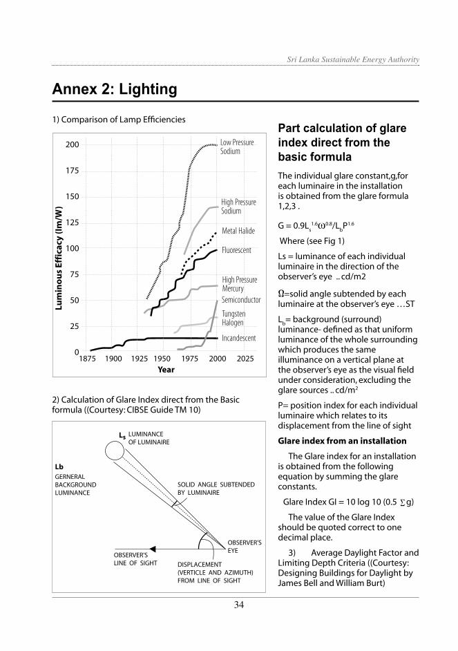
Sri Lanka Sustainable Energy Authority
Part calculation of glare index direct from the basic formulaThe individual glare constant,g,for each luminaire in the installation is obtained from the glare formula 1,2,3 .
G = 0.9Ls1.6ω0.8/L
bP1.6
Where (see Fig 1)
Ls = luminance of each individual luminaire in the direction of the observer’s eye .. cd/m2
Ω=solid angle subtended by each luminaire at the observer’s eye …ST
Lb= background (surround)
luminance- defined as that uniform luminance of the whole surrounding which produces the same illuminance on a vertical plane at the observer’s eye as the visual field under consideration, excluding the glare sources .. cd/m2
P= position index for each individual luminaire which relates to its displacement from the line of sight
Glare index from an installation
The Glare index for an installation is obtained from the following equation by summing the glare constants.
Glare Index GI = 10 log 10 (0.5 ∑g)
The value of the Glare Index should be quoted correct to one decimal place.
3) Average Daylight Factor and Limiting Depth Criteria ((Courtesy: Designing Buildings for Daylight by James Bell and William Burt)
Low PressureSodium
High PressureSodium
Metal Halide
Fluorescent
High PressureMercurySemiconductor
TungstenHalogen
Incandescent
200
175
150
125
100
75
50
25
01875 1900 1925 1950 1975 2000 2025
Lum
ino
us
Effi
cacy
(Im
/W)
Year
Ls LUMINANCEOF LUMINAIRE
SOLID ANGLE SUBTENDEDBY LUMINAIRE
OBSERVER'SEYE
OBSERVER'SLINE OF SIGHT DISPLACEMENT
(VERTICLE AND AZIMUTH)FROM LINE OF SIGHT
LbGERNERALBACKGROUNDLUMINANCE
Annex 2: Lighting
1) Comparison of Lamp Efficiencies
2) Calculation of Glare Index direct from the Basic formula ((Courtesy: CIBSE Guide TM 10)
3534

Sri Lanka Sustainable Energy Authority
D= W/A* (T Ө/ (1-R2))
Where
D = average daylight factor
W=window area in m2 (using table 5 to correct for framing)
A= area of all surfaces of the room in m2 (floor, ceiling and walls including windows)
T = glass transmittance ( from table 30 corrected for dirt ( using table 4)
Ө= visible sky angle, in degrees
R = average reflectance of area A (from table 2)
4. To be successfully day-lit from one side, the depth (L) of the room should be limited to meet the following condition:
L/w + L/h ≤2/ (1-Rb)
Where;
L =depth of room from window to back wall
w =width of the room measured across the window wall
h =height of the window head above the floor
Rb = area weighted average reflectance in the
back half of the room ( the value for a typical office is likely to be around 0.5)
Source BS Day light code 2 , pg 19
4 Recommended Illuminance Levels
4.1 Standard Maintained Illuminance
It is the responsibility of the Lighting Designer to select the illumination level required for any given task.
The Standard Maintained Illuminance values are tabulated in Table No. 2.10 and these values shall be the starting point for any lighting design. For further information on ‘Standard Maintained Illuminance’ for specific tasks, please refer “Code of Interior Lighting – 1994”, published by the Chartered Institution of Building services Engineers (CIBSE), UK.
w
H
L
r
Visiblesky angle
3534

Sri Lanka Sustainable Energy Authority
H/R0.00 0.10 0.20 0.30 0.40 0.50 0.60 0.70 0.80 0.90 1.00 1.10 1.20 1.30 1.40 1.50 1.60 1.70 1.80 1.90
1.00 1.26 1.53 1.90 2.35 2.86 3.50 4.20 5.00 6.00 7.00 8.10 9.25 10.35 11.70 13.15 14.70 16.20 - -1.05 1.22 1.46 1.80 2.20 2.75 3.40 4.10 4.80 5.80 6.80 8.00 9.10 10.30 11.60 13.00 14.60 16.10 - -1.12 1.30 1.50 1.80 2.20 2.66 3.18 3.88 4.60 5.50 6.50 7.60 8.75 9.85 11.20 12.70 14.00 15.70 - -1.22 1.38 1.60 1.87 2.25 2.70 3.25 3.90 4.60 5.45 6.45 7.40 8.40 9.50 10.85 12.10 13.70 15.00 - -1.32 1.47 1.70 1.96 2.35 2.80 3.30 3.90 4.60 5.40 6.40 7.30 8.30 9.40 10.60 11.90 13.20 14.60 16.00 -
1.43 1.60 1.82 2.10 2.48 2.91 3.40 3.98 4.70 5.50 6.40 7.30 8.30 9.40 10.50 11.75 13.00 14.40 15.70 -1.55 1.72 1.98 2.30 2.65 3.10 3.60 4.10 4.80 5.50 6.40 7.35 8.40 9.4 10.50 11.70 13.00 14.10 15.40 -1.70 1.88 2.12 2.48 2.87 3.30 3.78 4.30 4.88 5.60 6.50 7.40 8.50 9.50 10.50 11.70 12.85 14.00 15.20 -1.82 2.00 2.32 2.70 3.08 3.50 3.92 4.50 5.10 5.75 6.60 7.50 8.60 9.50 10.60 11.75 12.80 14.00 15.10 -1.95 2.20 2.54 2.90 3.30 3.70 4.20 4.75 5.30 6.00 6.75 7.70 8.70 9.65 10.75 11.80 12.90 14.00 15.00 16.00
2.11 2.40 2.75 3.10 3.50 3.91 4.40 5.00 5.60 6.20 7.00 7.90 8.80 9.75 10.80 11.90 12.95 14.00 15.00 16.002.30 2.55 2.92 3.30 3.72 4.20 4.70 5.25 5.80 6.55 7.20 8.15 9.00 9.90 10.95 12.00 13.00 14.00 15.00 16.002.40 2.75 3.12 3.50 3.90 4.35 4.85 5.50 6.05 6.70 7.50 8.30 9.20 10.00 11.02 12.10 13.10 14.00 15.00 16.002.55 2.90 3.30 3.70 4.20 4.65 5.20 5.70 6.30 7.00 7.70 8.55 9.35 10.20 11.20 12.25 13.20 14.00 15.00 16.002.70 3.10 3.50 3.90 4.35 4.85 5.35 5.85 6.50 7.25 8.00 8.70 9.50 10.40 11.40 12.40 13.25 14.05 15.00 16.00
2.85 3.15 3.65 4.10 4.55 5.00 5.50 6.20 6.80 7.50 8.20 8.85 9.70 10.55 11.50 12.50 13.30 14.05 15.02 16.002.95 3.40 3.80 4.25 4.75 5.20 5.75 6.30 7.00 7.65 8.40 9.00 9.80 10.80 11.75 12.60 13.40 14.20 15.05 16.003.10 3.55 4.00 4.50 4.90 5.40 5.95 6.50 7.20 7.80 8.50 9.20 10.00 10.85 11.85 12.75 13.45 14.20 15.10 16.003.25 3.70 4.20 4.65 5.10 5.60 6.10 6.75 7.40 8.00 8.65 9.35 10.10 11.00 11.90 12.80 13.50 14.20 15.10 16.003.43 3.86 4.30 4.75 5.20 5.70 6.30 6.90 7.50 8.17 8.80 9.50 10.20 11.00 12.00 12.82 13.55 14.20 15.10 16.00
3.50 4.00 4.50 4.90 5.35 5.80 6.40 7.10 7.70 8.30 8.90 9.60 10.40 11.10 12.00 12.85 13.60 14.30 15.10 16.003.60 4.17 4.65 5.05 5.50 6.00 6.60 7.20 7.82 8.45 9.00 9.75 10.50 11.20 12.10 12.90 13.70 14.35 15.10 16.003.75 4.25 4.72 5.20 5.60 6.10 6.70 7.35 8.00 8.55 9.15 9.85 10.60 11.30 12.10 12.90 13.70 14.40 15.15 16.003.85 4.35 4.80 5.25 5.70 6.22 6.80 7.40 8.10 8.65 9.30 9.90 10.70 11.40 12.20 12.95 13.70 14.40 15.20 16.003.95 4.40 4.90 5.35 5.80 6.30 6.0 7.50 8.20 8.80 9.40 10.00 10.80 11.50 12.25 13.00 13.75 14.45 15.20 16.00
4.00 4.50 4.95 5.40 5.85 6.40 6.95 7.55 8.25 8.85 9.50 10.05 10.85 11.55 12.30 13.00 13.80 14.50 15.25 16.004.07 4.55 5.05 5.47 5.95 6.45 7.00 7.65 8.35 8.95 9.55 10.10 10.90 11.60 12.32 13.00 13.80 14.50 15.25 16.004.10 4.60 5.10 5.53 6.00 6.50 7.05 7.70 8.40 9.00 9.60 10.16 10.92 11.63 12.35 13.00 13.80 14.50 15.25 16.004.15 4.62 5.15 5.56 6.05 6.55 7.08 7.73 8.45 9.05 9.65 10.20 10.95 11.65 12.35 13.00 13.80 14.50 15.25 16.004.20 4.65 5.17 5.60 6.07 6.57 7.12 7.75 8.50 9.10 9.70 10.23 10.95 11.65 12.35 13.00 13.80 14.50 15.25 16.004.22 4.67 5.20 5.65 6.12 6.60 7.15 7.80 8.55 9.12 9.70 10.23 10.95 11.65 12.35 13.00 13.80 14.50 15.25 16.00
Table 2.1.1A: Position Index Data
3736

Sri Lanka Sustainable Energy Authority
Table 2.10: Standard Maintained Illuminance
Standard maintained Characteristics of activity/ interior Representativeilluminance (lux) activities/interiors50 Interiors used rarely with visual tasks Cable tunnels, indoor s confined to movement and casual seeing storage tanks, walkway without perception of detail.100 Interiors used occasionally with visual Corridors, changing tasks confined to movement and casual rooms, bulk stores, seeing calling for only limited auditoria
perception of detail150 Interiors used occasionally or with visual Loading bays, medical
tasks not requiring perception of detail but stores, plant rooms involving some risk to people, plant or product
200 Interiors occupied for long periods, Foyers and entrances, or for visual tasks requiring some monitoring automatic perception of detail processes, casting concrete, turbine halls, dining rooms
300+ Interiors occupied for longer periods, Libraries, sports and or when visual tasks are moderately easy, assembly halls, i.e. large details > 10 min arc teaching spaces, and/ or high contrast. lecture theatres, packing
500† Visual tasks moderately difficult, i.e. details General offices, engine to be seen are of moderate size assembly, painting and (95 – 10 min arc) and may be of low contrast; spraying, kitchens, also colour judgment may be required. laboratories, retail
shops750† Visual tasks difficult, i.e. details to be seen Drawing offices,
are small (3 – 5 min arc) and of low contrast; ceramic decoration, also good colour judgment or the creation of meat inspection, chain a well lit, inviting interior may be required stores
1000† Visual tasks very difficult, i.e. details to be General inspection, seen are very small (2 – 3 min arc) and of electronic assembly, low contrast; also accurate colour judgments gauge and tool rooms, or the creation of well lit, inviting interior retouching paintwork, may be required cabinet making, supermarkets
1500† Visual tasks extremely difficult; i.e. details Fine work and to be seen extremely small (1 – 2 min arc) inspection, hand and of low contrast; optical aids and local tailoring, precision lighting may be of advantage assembly
2000† Visual tasks exceptionally difficult, i.e. details to Assembly of minute be seen exceptionally small (<1 min arc) with very mechanisms, finished low contrast; optical aids and local lighting fabric inspection will be of advantage
† 1 minute of arc (min arc) is 1/60 of a degree. This is the angle of which the tangent is given by the dimension of the task detail to be seen divided by the viewing distance. Courtesy: CIBSE Code of Interior Lighting – 1994)
3938

Sri Lanka Sustainable Energy Authority
Table 2.11: Design Maintained Illuminance
(Courtesy: CIBSE Code of Interior Lighting – 1994)
Standard maintained illuminance (lux)
Task size and contrast Task duration Erro risk
Design maintained illuminance (lux)
Are task details unusually difficult to see?
Are task details unusually easy to see?
Is task undertaken for unusually long time?
Is task undertaken for unusually short time?
Do errors have unusually serious consequences for people, plant or product?
Design Maintained IlluminanceHowever, depending on the task size and contrast, task duration and the risk, serious
consequences shall be taken into account in designing lighting systems for specific applications. The methodology that may be adopted for arriving at final illumination levels, which is known as “Design Maintained Illuminance”, is given in here.
200 Yes
Yes
Yes
Yes
200 200 200 200 200 200250 250 250 250 250 250
300 300 300 300 300 300 300400 400 400 400 400 400
500 500 500 500 500 500 500600 600 600 600 600 600
750 750 750 750 750 750 750900 900 900 900 900 900
1000 1000 1000 1000 1000 10001300 1300 1300
1300 1500 1500
standard maintainedilluminance
Design maintainedilluminance(lux)
Task size and contrast Task durarion Error risk
Are task details unusually difficult to see ?
Are task details unusually easy to see ?
Is task undertaken Is task undertaken for unusuallyshort time?
Do errors have unusually serious consequences for people, plant or product?
(lux)for unusuallylong time?
Yes
Yes
Yes
YesYesYesYesYesYes
YesYesYes
Yes
YesYes
YesYesYesYes
YesYesYesYesYesYes
YesYesYes
3938

Sri Lanka Sustainable Energy Authority
Limiting Glare IndexGenerally, two types of glares are encountered
in lighting applications and they are known as ‘Discomfort Glare’ and ‘Disability Glare’ (Please see the Annex 1 for definitions, Abbreviations and Acronyms)
Discomfort Glare is likely to be experienced when some part of the interior has much higher luminance/ brightness than that of the rest of the interior. This type of Glare can be estimated by ‘Glare Indices’ for which limiting values are given as ‘Limiting Glare Indices’ in the CIBSE Code of Interior Lighting – 1994. The contributory factor to such Glare is average luminance/ brightness in the field of view, position of the glare source and subtended angle of the glare source from the line of vision.
Disability Glare is generally experienced where a source of high luminance, brightness lies close to a task. In this case, the light from the source will be scattered in the eye across the retinal image of the task. The effect of this scattered
light is to reduce the contrast of the task and to change the local state of adaptation of the retina. Furthermore, the retinal image of the source with high Luminance/ brightness will induce changes in the operating state of the surrounding retinal area. The net effect of these changes is to reduce the visibility of the task which is known as ‘Disability Glare’.
Good general practices in selection of appropriate illuminance levels, luminaires and window blinds, correct positioning of light sources and minimising of shiny colours/ surfaces in the interior can generally eliminate both forms of glare.
The detail method for calculating Glare Indices is given in ‘Annex – 02 section 2 (Courtesy: CIBSE Guide TM 10)
For specific applications where particular illumination level to be achieved will be critical, target ranges given for Installed Power density in the CIBSE Code of Interior Lighting- 1994 shall be used.
Table 2.12: Installed Power Density(Courtesy: CIBSE Code of Interior Lighting – 1994)
Metal halide clear or coated 250-400 2 B,C,E 2.6-4.5 2.1-3.6 2.0-3.4 High pressure mercury-coated 250-400 3 B,C,E 4.2-6.2 3.5-5.1 3.3-4.8High pressure sodium improved colour -250-400 3 B,C,E 2.4-3.6 2.0-2.9 1.9-2.8 Standard or high efficiency -250-1000 4 B,C,E 1.4-2.7 1.2-2.2 1.1-2.1
Lamp type Wattage range CIE colour Luminaire Working plane used to calculate rendering maintenance power density target ranges group categories range (see Table 4.5, (W/m2/100 lux) page 153, and section 3.3.2)
(a) High bay industrial –reflectance C,W,F= 0.5,0.5,0.2 to 0.3,0.3,0.1
Room indexK=1 K=2.5 K=5
4140

Sri Lanka Sustainable Energy Authority
(b) Industrial – reflectance C,W,F= 0.7,0.5,0.2 to 0.3,0.5,0.2
Fluorescent triphosper 32-100 1b B,C,E 2.5-4.9 1.9-3.5 1.6-2.9halophospate 32-100 2-3 B,C,E 3.2-6.3 2.4-4.5 2.1-3.7Metal halide clear or coated 150-400 2 B,C,E 2.9-6.8 2.3-4.4 2.1-3.9High pressure mercury-coated 125-400 3 B,C,E 4.8-9.4 3.7-6.1 3.5-5.5High pressure sodium improved 150-400 3 B,C,E 2.7-5.5 2.1-3.5 2.0-3.2colour standard or 100-400 4 B,C,E 1.8-4.7 1.3-3.0 1.3-2.7
high efficiency
Fluorescent -triphosper 32-100 1b A,B,C,D,E 2.7-5.4 2.2-4.2 2.1-3.7-halophospate 32-100 2-3 A,B,C,D,E 3.4-7.0 2.8-5.4 2.6-4.8-compact 36-55 1b A,B,C,D,E 3.3-6.4 2.8-4.9 2.6-4.4Metal halide -clear or coated 150-400 2 B,C 4.4-7.1 3.6-5.7 3.4-5.3High pressure 125-400 3 B,C 6.6-9.9 5.4-7.9 5.1-7.3mercury-coated High pressure sodium improved colour 150-400 3 B,C 3.8-5.8 3.1-4.6 2.9-4.3
standard or high efficiency 100-400 4 B,C 2.4-4.9 2.0-3.9 1.9-3.6
5 Lighting Control Credits To encourage the use of lighting controls
beyond the mandatory switching requirements of Section 2.21.2, the connected lighting power within a building may be adjusted to take credit for the benefits of certain types of automatic lighting controls. The lighting control credit is a multiplier that reduces the amount of energy
used for lighting, giving a lower adjusted lighting power. In order to qualify for a lighting power density reduction, the control device must control all of the fixtures for which the credit is claimed. At least 50 % of the light output of the controlled luminaire must fall within the applicable type of space listed in Table 2.13. The list of the type of lighting controls that qualify for these credits is shown in Table 2.14.
( c) Commercial- reflectance C,W,F= 0.7,0.5,0.2 to 0.5,0.5,0.2
4140

Sri Lanka Sustainable Energy Authority
The lighting control credits listed in Tables 2.13 and 2.14 have the effect of reducing the actual lighting power for those portions of the building where the credit applies by the amount listed in the respective tables. The credits therefore make it easier to meet the allowed lighting power requirement.
In order to qualify power savings adjustments, the control system or device must control all of the fixtures in the areas for which the credit is claimed. At least 50 % of the light output of the controlled luminaire must fall within the applicable space listed in the table. Credits should not be combined.
Table 2.13: Power Credits for Certain Types of Lighting Controls
Rooms of any size that are used exclusively for storage 0.60 Rooms > 23 m2 0.10 0.05
Occupant Sensor (with separate sensor for each space)
Any space < or = 23 m2 enclosed by ceiling to floor partitions: any size classroom, corridor, conference or waiting room
Type of Control Type of Space Factor0.20
Automatic Time Switch Control Device
Room < or = 23 m2 and with a timed manual override at each switch location and controlling only the lights in the area enclosed by ceiling-height partitions
Table 2.14: Power Credits for Automatic Daylighting Controls
Glazing Stepped Dimming Controls Continuous Dimming Controls Properties
WWR WWR WWR WWR WWR WWR< 20% 20% to 40% > 40% < 20% 20% to 40% > 40% VLT 60% 0.20 0.30 0.40 0.30 0.40 0.40
VLT 35 and < 60% 0 0.20 0.30 0 0.30 0.40
VLT< 35% 0 0 0.20 0 0 0.40
4342

Sri Lanka Sustainable Energy Authority
Chilled Water Piping. For material with thermal resistance greater than 32 m² K/W per metre of thickness, the minimum insulation thickness, t (mm), is given by:
28 X Thickness in Table 3-1t =
Actual R Value
Chilled Water Piping. For material with thermal resistance less than 28 m² K/W per metre of thickness, the minimum insulation thickness, t (mm), is given by: 32 X Thickness in Table 3-1t =
Actual R Value
Air Handling System Insulation and DuctsThermal Resistance Requirement. The minimum thermal resistance, R (m2K/W), of the insulation, excluding film resistance shall be: 5TR =
47.3
wherein 5T = design temperature differential between the air in the duct and the surrounding air, measured in Kelvin.
Piping Fluid Temp Insulation Thickness for Nominal Pipe Sizes (mm)System Range (°C) Run outs 25 mm 32 mm to 63 mm Type Up to 50 mm and less 50 mm & above
Chilled 4.5-13 13 13 25 38 Water
Refrigerant Below 4.5 25 25 38 50 or Brine Notes:1. The insulation thickness is based on insulation having thermal resistance in the range of 28
to 32 m² K/W per metre of thickness on a flat surface at a mean temperature of 24° C. See 3.8.2 and 3.8.3 for insulation materials with thermal resistance outside this range.
2. These thicknesses are based on energy efficiency considerations only. Issues such as water vapor permeability or surface condensation may require vapor retarders or additional insulation.
Table 3.1: Piping Insulation
Annex 3: Ventilation & Air Conditioning Piping Insulation
4342
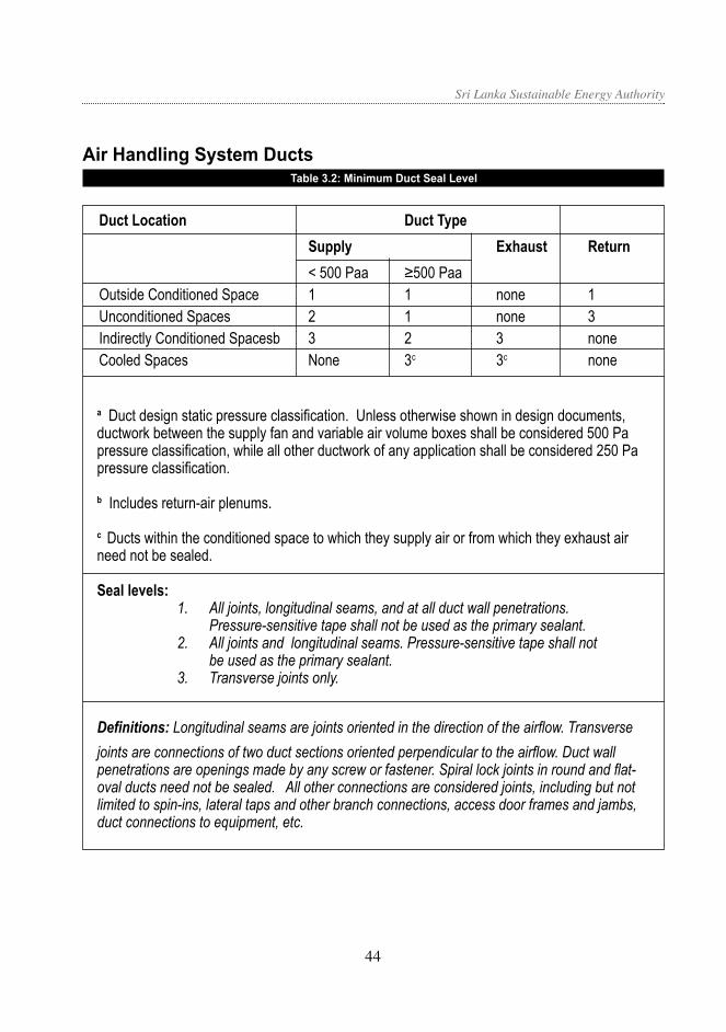
Sri Lanka Sustainable Energy Authority
Air Handling System DuctsTable 3.2: Minimum Duct Seal Level
Duct Location Duct Type Supply Exhaust Return < 500 Paa ≥500 Paa Outside Conditioned Space 1 1 none 1 Unconditioned Spaces 2 1 none 3 Indirectly Conditioned Spacesb 3 2 3 none Cooled Spaces None 3c 3c none
a Duct design static pressure classification. Unless otherwise shown in design documents, ductwork between the supply fan and variable air volume boxes shall be considered 500 Pa pressure classification, while all other ductwork of any application shall be considered 250 Pa pressure classification.
b Includes return-air plenums.
c Ducts within the conditioned space to which they supply air or from which they exhaust air need not be sealed.
Seal levels:1. All joints, longitudinal seams, and at all duct wall penetrations.
Pressure-sensitive tape shall not be used as the primary sealant. 2. All joints and longitudinal seams. Pressure-sensitive tape shall not
be used as the primary sealant. 3. Transverse joints only.
Definitions: Longitudinal seams are joints oriented in the direction of the airflow. Transverse joints are connections of two duct sections oriented perpendicular to the airflow. Duct wall penetrations are openings made by any screw or fastener. Spiral lock joints in round and flat-oval ducts need not be sealed. All other connections are considered joints, including but not limited to spin-ins, lateral taps and other branch connections, access door frames and jambs, duct connections to equipment, etc.
4544

Sri Lanka Sustainable Energy Authority
Comfort Zone DiagramDew point/T diagram showing the comfort zone according to ASHRAE 55-1992
20 0C WET BULB18 0C WET BULB
DEW
PO
INT
TEM
PERA
TURE
0 C
DRY BULB TEMPERATURE 0C
20
15
10
20
20ET0 20ET0
25 3015
15
5
10
0
WINTER
SUMMER
HU
MID
ITY
RA
TIO
70%
100%
60%
50%
30%
EFFE
CTI
VE
TEM
PER
ATU
RE
ET0
5
0
-5
-10
4544

Sri Lanka Sustainable Energy Authority
46 47
Table 4.1: Solar Correction Factors (CF) (dimensionless)
South North East West SE NE SW NW
0.95 0.79 1.34 0.90 1.15 1.07 0.93 0.85
Annex 4: Building Envelope
1. Appendix 4a
Where the terms are defined as:
OTTVi = overall thermal
transmittance value for the ith specific wall orientation and construction combination, (W/m2)
Teq
= equivalent indoor-outdoor temperature difference through the opaque wall section, (19.3°C)
= solar absorptance of the exterior opaque wall (dimensionless)
WWR = window-to-wall ratio, using the gross wall area in the denominator, (dimensionless).
Uw = thermal transmittance of
opaque wall section, (W/m2°C)
T = temperature difference through the window section, (3.6°C)
Uf = thermal transmittance of
window section, (W/ m2°C)
SF = solar factor, defined as the average hourly value of solar energy incident on vertical windows, (186 W/m2)
SC = shading coefficient of the fenestration system as given in Section Annex 4d, (dimensionless)
CF = solar correction factor for the orientation of the fenestration
2. Appendix 4bTable of Thermal Properties of Typical
Construction Material for Estimating U-values for facades. (Source: ASHRAE Fundamentals Handbook)
3. Appendix 4cSolar Correction Factor for Fenestrations (CF)
4746

Sri Lanka Sustainable Energy Authority
46 47
4. Appendix 4dCombined Shading Coefficients (SC)
Table 4.2: Shading Coefficient (SC) for Horizontal Overhang Projections
Orientation
R1 South North East West SE NE SW N W
0.2 0.69 0.77 0.80 0.76 0.75 0.79 0.72 0.76
0.4 0.53 0.68 0.68 0.59 0.61 0.68 0.56 0.64
0.6 0.45 0.63 0.58 0.50 0.52 0.61 0.47 0.56
0.8 0.39 0.59 0.50 0.43 0.45 0.54 0.41 0.51
1.0 0.37 0.56 0.43 0.40 0.40 0.50 0.38 0.48
1.2 0.36 0.54 0.39 0.37 0.37 0.46 0.36 0.46
1.4 0.35 0.53 0.35 0.36 0.35 0.44 0.35 0.44
1.6 0.34 0.52 0.32 0.35 0.33 0.42 0.34 0.43
1.8 0.33 0.51 0.29 0.34 0.31 0.40 0.34 0.42
2.0 0.33 0.50 0.27 0.33 0.30 0.38 0.33 0.42
Table 4.3: Shading Coefficient (SC) for Vertical Side-Fin Projections
Orientation
R2 South North East West SE NE SW NW
0.2 0.80 0.80 0.87 0.84 0.83 0.83 0.82 0.82
0.4 0.75 0.75 0.83 0.79 0.79 0.79 0.77 0.77
0.6 0.71 0.70 0.79 0.75 0.75 0.75 0.73 0.73
0.8 0.69 0.68 0.77 0.73 0.73 0.73 0.71 0.71
1.0 0.67 0.66 0.75 0.71 0.71 0.71 0.69 0.68
1.2 0.67 0.66 0.75 0.71 0.71 0.70 0.69 0.68
1.4 0.66 0.64 0.74 0.70 0.70 0.69 0.68 0.67
1.6 0.66 0.64 0.73 0.70 0.70 0.69 0.68 0.67
1.8 0.66 0.64 0.73 0.69 0.69 0.68 0.67 0.67
2.0 0.65 0.63 0.72 0.69 0.69 0.68 0.67 0.66
4746

Sri Lanka Sustainable Energy Authority
Orientation
R1 R2 South North East West SE NE SW NW
0.2 0.2 0.52 0.60 0.72 0.62 0.62 0.66 0.57 0.61
0.2 0.4 0.31 0.46 0.53 0.41 0.42 0.49 0.36 0.44
0.2 0.6 0.21 0.36 0.40 0.27 0.31 0.38 0.24 0.32
0.2 0.8 0.17 0.30 0.28 0.18 0.23 0.29 0.18 0.24
0.2 1.0 0.13 0.25 0.18 0.13 0.15 0.22 0.13 0.19
0.4 0.2 0.48 0.55 0.65 0.58 0.56 0.60 0.53 0.56
0.4 0.4 0.27 0.42 0.50 0.37 0.38 0.46 0.32 0.39
0.4 0.6 0.20 0.34 0.37 0.25 0.28 0.36 0.23 0.30
0.4 0.8 0.15 0.28 0.26 0.16 0.20 0.27 0.15 0.22
0.4 1.0 0.22 0.37 0.30 0.23 0.26 0.34 0.23 0.30
0.6 0.2 0.43 0.50 0.62 0.53 0.53 0.56 0.48 0.52
0.6 0.4 0.25 0.40 0.47 0.35 0.36 0.43 0.30 0.37
0.6 0.6 0.18 0.31 0.35 0.23 0.26 0.33 0.20 0.27
0.6 0.8 0.24 0.39 0.34 0.26 0.29 0.37 0.25 0.32
0.6 1.0 0.18 0.32 0.23 0.19 0.21 0.28 0.19 0.26
0.8 0.2 0.42 0.48 0.60 0.52 0.51 0.54 0.47 0.50
0.8 0.4 0.23 0.37 0.44 0.33 0.34 0.41 0.28 0.35
0.8 0.6 0.26 0.42 0.41 0.28 0.34 0.42 0.27 0.35
0.8 0.8 0.20 0.34 0.28 0.21 0.24 0.31 0.21 0.28
0.8 1.0 0.15 0.27 0.20 0.15 0.17 0.24 0.15 0.21
1.0 0.2 0.40 0.45 0.58 0.49 0.49 0.52 0.44 0.47
1.0 0.4 0.29 0.46 0.50 0.35 0.39 0.48 0.32 0.40
1.0 0.6 0.22 0.37 0.35 0.24 0.28 0.36 0.23 0.31
1.0 0.8 0.16 0.29 0.24 0.17 0.20 0.27 0.17 0.23
1.0 1.0 0.13 0.25 0.17 0.13 0.15 0.21 0.13 0.19
1.2 0.2 0.36 0.51 0.60 0.45 0.48 0.55 0.41 0.48
1.2 0.4 0.25 0.41 0.43 0.31 0.34 0.42 0.28 0.36
1.2 0.6 0.18 0.32 0.32 0.20 0.25 0.32 0.19 0.26
1.2 0.8 0.15 0.28 0.21 0.16 0.18 0.24 0.15 0.22
1.2 1.0 0.11 0.22 0.13 0.11 0.12 0.18 0.11 0.17
Table 4.4: Shading Coefficient (SC) for Horizontal & Vertical “Egg-Crate” Projections
4948

Sri Lanka Sustainable Energy Authority
Annex 5: Electrical Power and Distribution
5.4.6 Motor Rewinding: Motor users should insist on proper rewinding practices for rewound motors. If the following practices cannot be assured, the damaged motor should be replaced with a new, efficient one rather than suffer the significant efficiency penalty associated with typical rewind practices. Wherever possible, the following practices (taken from “Guidelines for Maintaining Motor Efficiency During Rebuilding”, Electrical Apparatus Service Association, St. Louis, MO, USA) should be followed for rewinding:
(a) Conduct a stator-core loss test before and after stripping.
(b) Repair or replace defective laminations.
(c) Calibrate all test equipment and measuring devices at least annually against standards traceable to the National Standard.
(d) Measure and record winding resistance and room temperature.
(e) Measure and record no-load amps and voltage during the final test to measure
efficiency.
(f ) Have a quality assurance program.
(g) Have and use, at a minimum, the following test equipment; ammeter, voltmeter, wattmeter, ohmmeter, megohmmeter, and high potential tester.
(h) Have a three-phase power supply for running motors at rated voltage.
(i) Balance the rotor.
(j) Do not heat stators above 3500C.
(k) Do not sandblast the iron core.
(l) Do not knurl, peen, or paint bearing fits.
(m) Do not use an open flame for stripping.
(n) Do not grind the laminations or file the slots.
(o) Do not increase the air gap.
(p) Do not increase the resistance of the windings.
(q) Do not make mechanical modifications without the customer’s prior approval.
This includes but is not limited to changing fans, types of bearings, shaft material,
and seals.
(r) Do not change the winding design.
Minimum Pipe Insulation Thickness (in.)
Conductivity at 100 ° F 0.24 to 0.28 [Btu-in/(h-ft2- ° F)]
(type of closed-cell foam or high performance rigid preshaped fiberglass)
Nominal Pipe Diameter 0.5 Runouts up to 2 in. (<12 ft length)
2 in. and less 1.0
2.5 in. and larger 1.5
Table 6.1: Minimum Pipe Insulation Thicknesses for Service Hot Water Systems
Annex 6: Service Water Heating
4948

Sri Lanka Sustainable Energy Authority
Sri Lanka Sustainable Energy Authority 3G-4A, BMICH, Bauddahloka Mawatha,
Colombo 07, Sri Lanka.
E-mail: [email protected] / web: www.energy.gov.lk TP: +94(0)11 2677445 / Fax: +94(0)11 2682534