SRH System – Stress Release Hole/s A substitution to ...
16
Journal of Engineering Geology Volume XLV, Nos. 1 & 2 A bi-annual Journal of ISEG June-December 2020 1 SRH System – Stress Release Hole/s A substitution to conventional yield support system Bineshian, H Aberfoyle Park, SA 5159, Australia [email protected] Received June 2020/Accepted August 2020 Abstract This paper aims to propose a new identification and classification system for SSH ground as well as introducing SRH System all in one as a manual for tunnelling under SSH condition. SRH is a system of 100 + mm diameter holes without casing, which are drilled with a spacing of almost 2000 by 2000 mm in a square pattern and radial orientation perpendicular to the surface of periphery of tunnel in one to three stages depending on the severity of convergency. Maximum required length of the holes equals to the diameter of tunnel to ensure it crosses the generated plastic zone around the periphery of tunnel to assist with releasing the non-uniform shear stresses that produces non-uniform deformation in complicated load configuration of SSH condition. It minimises the transfer of deformation to the periphery of tunnel from plastic zone generated around the underground opening by controling the accumulation of stresses at surrounding ground due to the SSH condition. It diverts the stresses towards the free spaces created by SRH and will release the deformation into hollow space of holes. SRH System is verified during a course of 5 years in practice to replace the time- and cost-inefficient CYSS. It has been first ever introduced by author in 2015 and been successfully applied in USBRL Projects till now resulting in overcoming the SSH challenges/hazards with saving in time and cost and retaining the safety level. Keywords: heaving, liner stress controller, squeezing, SRH, SSH, stress release hole/s, swelling, TH, yield support system Nomenclature (I) I-System NATM New Austrian Tunnelling Method (I)-Class I-System’s Ground Classification PPV Peak Particle Velocity in mm/sec 3DM 3-Dimensional Monitoring PU-2C Polyurethane – 2 Components 3DMS 3DM Station RingC Ring or Invert Closure BRT Bi-Reflex Target RMR Rock Mass Rating C Convergency in mm RSS Rigid Support System CYSS Conventional Yield Support System SDA Self-Drilling Anchor D Tunnel’s diameter, width, or height (mm) SN Store Norfors DIC Digital Image Correlation SRH Stress Release Hole/s ET Escape Tunnel SS Support System FRS Fibre Reinforced Shotcrete SSH Squeezing, Swelling, Heaving HEAM High Energy Absorption Mesh SysDB Systematic Dynamic Bolting L Length in mm TBM Tunnel Boring Machine LCN Longitudinal Compression Niche TH Toussaint-Heintzmann Profile LG Lattice Girder YieldB Yielding Bolts including SysDB LSC Liner Stress Controller YieldFRS Yield FRS with embedded LSC McNally A System for Rock Burst Treatment YieldR Yield Ribs – TH or H Profile MSP Mild Steel Plate YSS Yield Support System MT Main Tunnel
Transcript of SRH System – Stress Release Hole/s A substitution to ...

Journal of Engineering Geology Volume XLV, Nos. 1 & 2 A bi-annual Journal of ISEG June-December 2020
1
SRH System – Stress Release Hole/s A substitution to conventional yield support system
Bineshian, H
Aberfoyle Park, SA 5159, Australia [email protected]
Received June 2020/Accepted August 2020
Abstract
This paper aims to propose a new identification and classification system for SSH ground as well as introducing SRH System all in one as a manual for tunnelling under SSH condition. SRH is a system of 100+ mm diameter holes without casing, which are drilled with a spacing of almost 2000 by 2000 mm in a square pattern and radial orientation perpendicular to the surface of periphery of tunnel in one to three stages depending on the severity of convergency. Maximum required length of the holes equals to the diameter of tunnel to ensure it crosses the generated plastic zone around the periphery of tunnel to assist with releasing the non-uniform shear stresses that produces non-uniform deformation in complicated load configuration of SSH condition. It minimises the transfer of deformation to the periphery of tunnel from plastic zone generated around the underground opening by controling the accumulation of stresses at surrounding ground due to the SSH condition. It diverts the stresses towards the free spaces created by SRH and will release the deformation into hollow space of holes. SRH System is verified during a course of 5 years in practice to replace the time- and cost-inefficient CYSS. It has been first ever introduced by author in 2015 and been successfully applied in USBRL Projects till now resulting in overcoming the SSH challenges/hazards with saving in time and cost and retaining the safety level. Keywords: heaving, liner stress controller, squeezing, SRH, SSH, stress release hole/s, swelling, TH, yield support system Nomenclature (I) I-System NATM New Austrian Tunnelling Method (I)-Class I-System’s Ground Classification PPV Peak Particle Velocity in mm/sec 3DM 3-Dimensional Monitoring PU-2C Polyurethane – 2 Components 3DMS 3DM Station RingC Ring or Invert Closure BRT Bi-Reflex Target RMR Rock Mass Rating C Convergency in mm RSS Rigid Support System CYSS Conventional Yield Support System SDA Self-Drilling Anchor D Tunnel’s diameter, width, or height (mm) SN Store Norfors DIC Digital Image Correlation SRH Stress Release Hole/s ET Escape Tunnel SS Support System FRS Fibre Reinforced Shotcrete SSH Squeezing, Swelling, Heaving HEAM High Energy Absorption Mesh SysDB Systematic Dynamic Bolting L Length in mm TBM Tunnel Boring Machine LCN Longitudinal Compression Niche TH Toussaint-Heintzmann Profile LG Lattice Girder YieldB Yielding Bolts including SysDB LSC Liner Stress Controller YieldFRS Yield FRS with embedded LSC McNally A System for Rock Burst Treatment YieldR Yield Ribs – TH or H Profile MSP Mild Steel Plate YSS Yield Support System MT Main Tunnel

Journal of Engineering Geology Volume XLV, Nos. 1 & 2 A bi-annual Journal of ISEG June-December 2020
2
1. Introduction Several definitions for squeezing and swelling are proposed by authors. Terzaghi (1946) defines the squeezing and swelling as a plastification procedure in a medium containing mica and/or considerable amount of clay; squeezing causes slow and small volume increase while swelling generates rapid and large increase in volume. Gioda (1982) defines the squeezing in a different form as a time dependent deformation that is generated by concentration of shear stresses around the excavation periphery. Kovari (1988) defines the squeezing as a procedure in which rock is stressed to its bearing capacity and fails in yielding manner in contrast to brittle failure. Olsen and Palmström (1989) defines the squeezing as time dependant shear displacement. Likewise, Singh et al (1992) describes the squeezing as a form of creep; a time dependent behaviour, which causes cross section area of tunnel gradually to be reduced. Olsen and Palmström (1990) defines swelling differently from squeezing; they describe the swelling a physio-chemical reaction, which is combined with stress relief. In explanation on cause of squeezing, Aydan et al (1993) stated that tunnel closure due to squeezing is because of four possible forms of failure; buckling failure, complete shear failure, shearing and sliding failure, and tensile splitting. Barla (1995) describes the squeezing as large time-dependent convergence during tunnel excavation, which takes place when a particular combination of induced stresses and material properties pushes some zones around the tunnel beyond the limiting shear stress at which creep starts; deformation may terminate during construction or may continue over a long period of time. There are several approaches proposed by researchers in categorization of squeezing, including empirical and analytical methods. Singh et al (1992) and Goel et al (1995) proposed empirical approaches for predicting squeezing conditions. Later on, Singh and Goel (1999) proposed a categorization for degree of squeezing based on the convergency of tunnel. Hoek (2001) classified squeezing ground conditions based on tunnel strain and the ratio of rock mass strength and in situ stress. Shrestha (2005) observed that the rock mass strength has a significant influence on squeezing phenomena. Further to the empirical approaches, Jethwa et al (1984), Aydan et al (1993), and Hoek and Marinos (2000) proposed a semi-empirical tool using closed form analytical solutions for a circular tunnel to predict squeezing and to estimate expected deformation around the tunnel. Hadjigeorgiou and Karampinos (2017) addressed an appropriate engineering tools that can be used for the prediction of squeezing. Considering the effect of excavation technique on squeezing behaviour, Barla et al (2014) proposed a guideline for bored tunnels under squeezing condition by elasto-visco-plastic continuum model and Mata (2018) has shown that long term deformation of tunnel excavated by drill and blast are significantly higher than mechanised bored tunnel. Although, the causes resulting in squeezing and swelling behaviour is different, it is often difficult to distinguish between squeezing and swelling, as the two phenomena may occur at the same time and induce similar effects (Barla, 2002). This paper aims to propose a manual for tunnelling under SSH condition containing a new identification and classification system for SSH condition and an introduction to SRH System. While SRH has been cited in technical papers, design documents, and reports by author since 2015, it is published here for the first time as an individual subject, which makes it available to engineers and geologists who work in challenging SSH ground or researchers who are interested in this field.
Journal of Engineering Geology Volume XLV, Nos. 1 & 2 A bi-annual Journal of ISEG June-December 2020
3
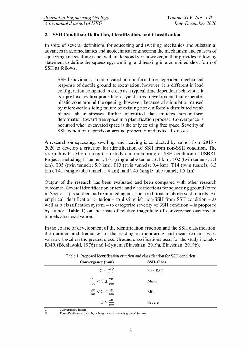
2. SSH Condition; Definition, Identification, and Classification In spite of several definitions for squeezing and swelling mechanics and substantial advances in geomechanics and geotechnical engineering the mechanism and cause/s of squeezing and swelling is not well understood yet; however, author provides following statement to define the squeezing, swelling, and heaving in a combined short form of SSH as follows;
SSH behaviour is a complicated non-uniform time-dependent mechanical response of ductile ground to excavation; however, it is different in load configuration compared to creep as a typical time dependent behaviour. It is a post-excavation procedure of yield stress development that generates plastic zone around the opening, however; because of stimulation caused by micro-scale sliding failure of existing non-uniformly distributed weak planes, shear stresses further magnified that initiates non-uniform deformation toward free space in a plastification process. Convergence is occurred when excavated space is the only existing free space. Severity of SSH condition depends on ground properties and induced stresses.
A research on squeezing, swelling, and heaving is conducted by author from 2015 - 2020 to develop a criterion for identification of SSH from non-SSH condition. The research is based on a long-term study and monitoring of SSH condition in USBRL Projects including 11 tunnels; T01 (single tube tunnel; 3.1 km), T02 (twin tunnels; 5.1 km), T05 (twin tunnels; 5.9 km), T13 (twin tunnels; 9.4 km), T14 (twin tunnels; 6.3 km), T41 (single tube tunnel; 1.4 km), and T45 (single tube tunnel; 1.5 km). Output of the research has been evaluated and been compared with other research outcomes. Several identification criteria and classifications for squeezing ground (cited in Section 1) is studied and examined against the conditions in above-said tunnels. An empirical identification criterion – to distinguish non-SSH from SSH condition – as well as a classification system – to categorise severity of SSH condition – is proposed by author (Table 1) on the basis of relative magnitude of convergence occurred in tunnels after excavation. In the course of development of the identification criterion and the SSH classification, the duration and frequency of the reading in monitoring and measurements were variable based on the ground class. Ground classifications used for the study includes RMR (Bieniawski, 1976) and I-System (Bineshian, 2019a, Bineshian, 2019b).
Table 1. Proposed identification criterion and classification for SSH condition Convergency (mm) SSH-Class
C ≤ !.#$%!!
Non-SSH
!.#$%!!
< C ≤ &$%!!
Minor
&$%!!
< C ≤ '$%!!
Mild
C > '$%!!
Severe
C Convergency in mm D Tunnel’s diameter, width, or height (whichever is greater) in mm

Journal of Engineering Geology Volume XLV, Nos. 1 & 2 A bi-annual Journal of ISEG June-December 2020
4
3. SSH Ground; Challenges and Conventional Resolution Required support systems for controlling and/or treating the SSH ground can be categorised into two main classes in principle:
- Rigid Support System (RSS) - Yield/Ductile Support System (YSS)
RSS is a stiff system of measures to resist against any induced deflection/deformation due to SSH behaviour by absorbing entire stresses generated by SSH accumulative load configuration. This system contains heavy measures to capacitate it for standing against incremental SSH load. RSS is applicable for passive load configuration in gravity driven ground and shallow depth overburden with less arch effect; author does not recommend this system to be applied as SS for tunnelling in SSH ground because it will lose the yield strength when it get aged; therefore, structure will lose load bearing capacity and as a result the tunnel may collapse; e.g., failure of concrete liner at Pernem Tunnel in Goa state in India after 22 years of commissioning in 1998; this railway tunnel is partly placed in SSH ground using application of RSS. YSS, which also called ductile support system is designed to accommodate the deformations that is induced to the periphery of tunnel in SSH ground by controlled yielding to prevent/terminate the accumulation of SSH load surrounding the tunnel structure. Application of YSS in its conventional form (CYSS) involved with following techniques in excavation and in execution of support system; a. Reaming: Over-excavation or overcutting of periphery of tunnel with slightly larger
diameter than designated size of cross section should be conducted prior to any deformation taken place to permit ground deformation within a permissible convergence (Figure 1a). It may work for Non-SSH, and Minor to Mild SSH condition (Table 1); however, it may not be considered as a sole resolution.
b. Longitudinal Compression Niches (LCN): It is made in the shotcrete in order to release the load within the allowable aperture of the niches (Figure 1b); however, it should be infilled with ductile material (e.g., rubber, spring, soft timber, or rolled MSP). This concept was first introduced in 1971 (Schubert, 1996, Barla, 2002).
c. Liner Stress Controller (LSC): Embedded LSC in FRS (Figure 1c) makes a system of YieldFRS, which functions almost as same as LCN with higher load control. Application of LSC together with load bearing ring of yield shotcrete is a time-consuming and cost overrun procedure. Advancement using this system produces less progress compared to normal tunnelling.
d. Yield Ribs (YieldR): Yield ribs or sliding ribs are applied to release accumulated load in a controlled manner. TH is most known profile for sliding ribs since 1932 (Figure 1d). Author has designed and applied H profile sliding ribs as a cost-efficient replacement for TH in T05 tunnel in USBRL Projects in 2015 (Figure 2). Concrete backfilling of void behind TH/H/LG ribs is not recommended; expended tyres or PU-2C are good options for backfilling, which function as a damper for SSH load.
e. Yielding Bolts (YieldB): A system of anchors/bolts with length greater than the depth of plastic zone of tunnel (L = 0.5D) actively assist in control of SSH behaviour. SysDB is the main member of a ductile bolting system – they can elongate under tensile stresses – that is applied to control the deformation caused

Journal of Engineering Geology Volume XLV, Nos. 1 & 2 A bi-annual Journal of ISEG June-December 2020
5
by SSH behaviour within the plastic zone at periphery of tunnel. In absence or unavailability of dynamic bolts, other types of ductile rock bolting system (Swellex or ductile SN/SDA) may be applicable depending on SSH-Class.
f. Convergency Measurements: Measuring and monitoring of deformation using convergency chord meter or 3DM is necessary to identify the SSH behaviour for required action. It is a common practice in tunnelling under any condition.
g. Instrumentation: Application of sliding ribs requires a precise and regular instrumentation for measuring and monitoring of stress regime on the ribs using load-/pressure-cells. In case, the deformations are exceeded the threshold of convergence limits, which are determined in plastic zone analysis, installation of single or multi-rod extensometer may be required. Instrumentation, measurements, monitoring, and deformation control when sliding ribs are used are additional measures, which makes tunnelling procedure time-inefficient.
a. Typical reaming
b. Typical LCN in FRS liner
c. Schematic of LSC embedded in FRS liner
d. TH profile, TH sliding rib, and clamp
Figure 1. CYSS elements.
Figure 2. Proposed H profile and invented clamp for H sliding rib
Journal of Engineering Geology Volume XLV, Nos. 1 & 2 A bi-annual Journal of ISEG June-December 2020
6
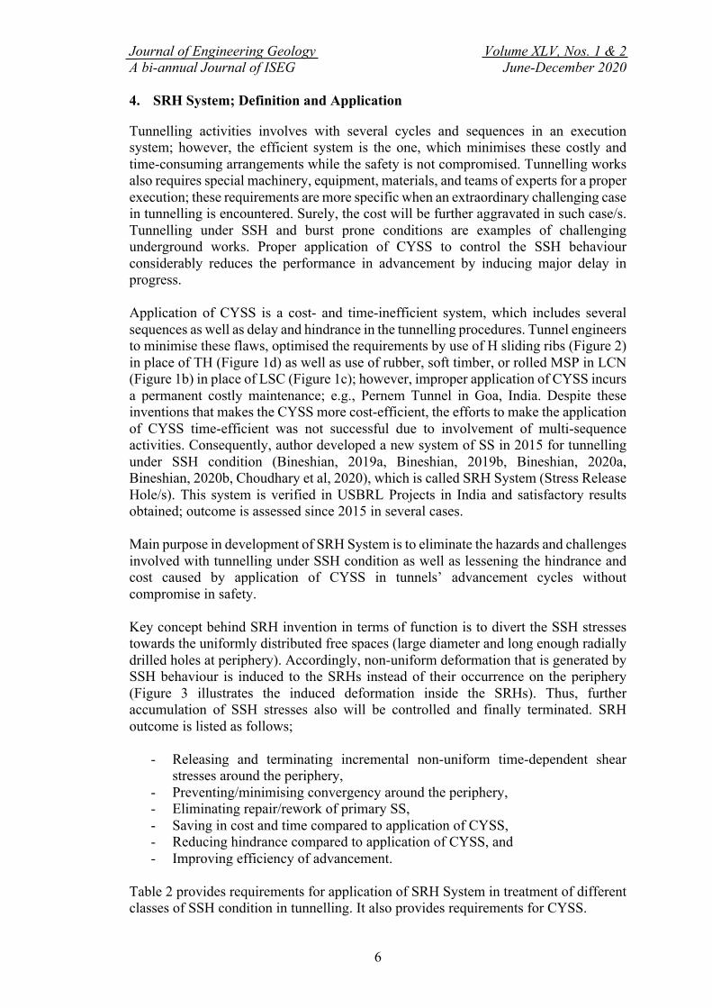
4. SRH System; Definition and Application Tunnelling activities involves with several cycles and sequences in an execution system; however, the efficient system is the one, which minimises these costly and time-consuming arrangements while the safety is not compromised. Tunnelling works also requires special machinery, equipment, materials, and teams of experts for a proper execution; these requirements are more specific when an extraordinary challenging case in tunnelling is encountered. Surely, the cost will be further aggravated in such case/s. Tunnelling under SSH and burst prone conditions are examples of challenging underground works. Proper application of CYSS to control the SSH behaviour considerably reduces the performance in advancement by inducing major delay in progress. Application of CYSS is a cost- and time-inefficient system, which includes several sequences as well as delay and hindrance in the tunnelling procedures. Tunnel engineers to minimise these flaws, optimised the requirements by use of H sliding ribs (Figure 2) in place of TH (Figure 1d) as well as use of rubber, soft timber, or rolled MSP in LCN (Figure 1b) in place of LSC (Figure 1c); however, improper application of CYSS incurs a permanent costly maintenance; e.g., Pernem Tunnel in Goa, India. Despite these inventions that makes the CYSS more cost-efficient, the efforts to make the application of CYSS time-efficient was not successful due to involvement of multi-sequence activities. Consequently, author developed a new system of SS in 2015 for tunnelling under SSH condition (Bineshian, 2019a, Bineshian, 2019b, Bineshian, 2020a, Bineshian, 2020b, Choudhary et al, 2020), which is called SRH System (Stress Release Hole/s). This system is verified in USBRL Projects in India and satisfactory results obtained; outcome is assessed since 2015 in several cases. Main purpose in development of SRH System is to eliminate the hazards and challenges involved with tunnelling under SSH condition as well as lessening the hindrance and cost caused by application of CYSS in tunnels’ advancement cycles without compromise in safety. Key concept behind SRH invention in terms of function is to divert the SSH stresses towards the uniformly distributed free spaces (large diameter and long enough radially drilled holes at periphery). Accordingly, non-uniform deformation that is generated by SSH behaviour is induced to the SRHs instead of their occurrence on the periphery (Figure 3 illustrates the induced deformation inside the SRHs). Thus, further accumulation of SSH stresses also will be controlled and finally terminated. SRH outcome is listed as follows;
- Releasing and terminating incremental non-uniform time-dependent shear stresses around the periphery,
- Preventing/minimising convergency around the periphery, - Eliminating repair/rework of primary SS, - Saving in cost and time compared to application of CYSS, - Reducing hindrance compared to application of CYSS, and - Improving efficiency of advancement.
Table 2 provides requirements for application of SRH System in treatment of different classes of SSH condition in tunnelling. It also provides requirements for CYSS.

Journal of Engineering Geology Volume XLV, Nos. 1 & 2 A bi-annual Journal of ISEG June-December 2020
7
a. Minor-SSH
b. Mild SSH c. Severe SSH
Figure 3. Illustration of observed patterns of induced deformation inside the SRH
Table 2. Proposed guideline for requirements in application of SRH and/or CYSS for SSH conditions
Main Required Resources SSH-Class
Minor* Mild* Severe* CYSS SRH CYSS SRH CYSS SRH
Reaming n/a n/a a n/a a a
YieldR ^ a n/a a n/a a a
LG (If TH or H profile is not used) a n/a n/a c/a n/a c/a
RingC< n/a n/a a n/a a c/a
FRS a a a a a a
LCN> a n/a a n/a a a
LSC and laxation of clamps> a n/a a n/a a n/a
YieldB using SysDB (L = 0.5D) n/a n/a a n/a a a
YieldB using SN, SDA, Swellex (L = 0.5D) a n/a n/a a n/a n/a
Drilling of 100+ mm holes for SRH (L = 1D) n/a a n/a a n/a a
3DM or Chord Convergency Meter@ a a a a a a
DIC @ 25 m n/a n/a a a n/a n/a
Strain Meter @ 100 m a n/a a n/a a a
Pressure Cell or Load Cell @ 150 m a n/a a n/a a a
Single-/Multi-Rod Extensometer @ 300 m n/a n/a a n/a a a
Strain Gauge @ 400 m n/a n/a n/a n/a a a * See Table 1. ^ TH or H profile capable of sliding; See Figures 1 and 2. < Ring Closure or Invert Closure; It is recommended to be applied to prevent heaving; however, its applicability depends
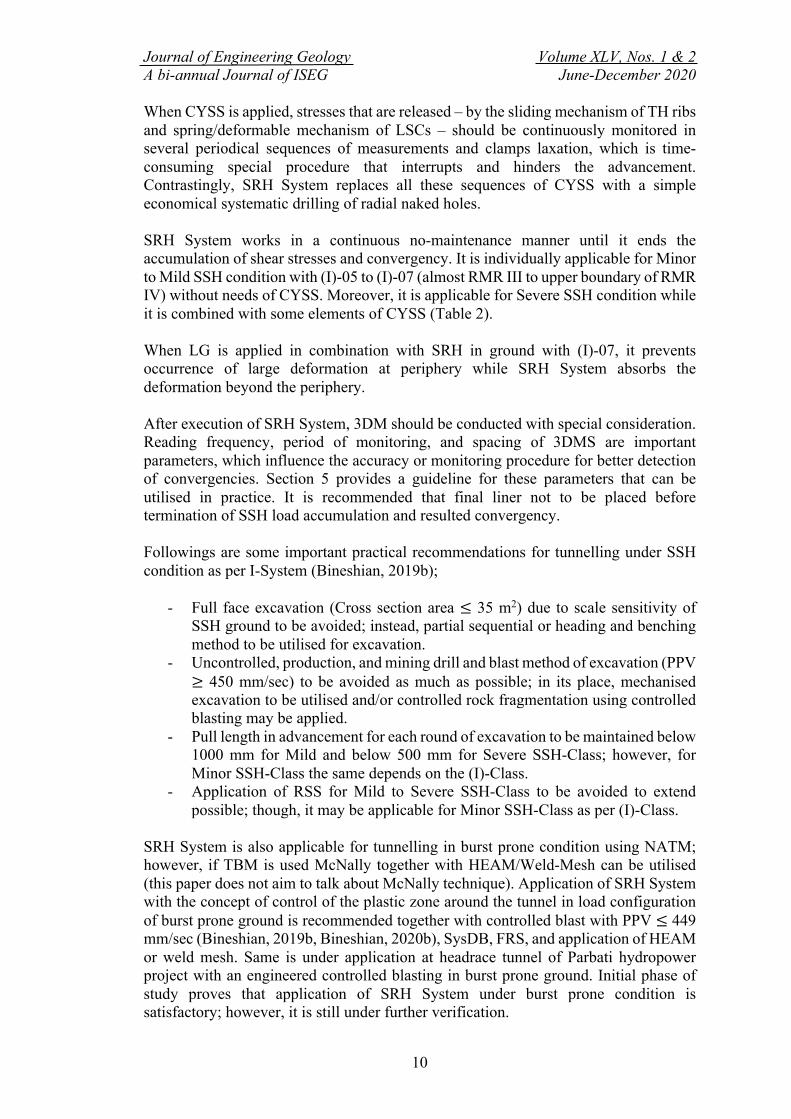
on observations, SSH-Class, and (I)-Class to be decided by Engineer at site. > Figure1. Skilled team for installation and deformation control is required. @ Spacing between the measuring stations (Table 3) a Applicable c/a Conditionally Applicable; applicable for (I)-07; not applicable for (I)-05 and (I)-06 D Tunnel’s diameter, width, or height (whichever is greater) in mm L Length in mm n/a Not Applicable SRH System is applied in a systematic pattern of large diameter drilled holes (100+ mm) in an individual system as shown in Figures 4 and 5 or combined with other measures (Figures 1 and 2 and Table 2) depending on the severity of convergency (Table 1). Sequences of application of SRH is different for ground classes depending on severity of SSH behaviour (Table 1). Ordinary rotary-percussion drilling system can be used.
0° 45° 90° 135°

Journal of Engineering Geology Volume XLV, Nos. 1 & 2 A bi-annual Journal of ISEG June-December 2020
8
a. Stage I ( ) – Minor-SSH; L = D
b. Stage II ( + ) – Mild-SSH; L = D
c. Stage III ( + + ) – Severe-SSH; L = D Figure 4. Proposed SRH drilling pattern – plan view
%.%.
%.%.
����
�������
%.%.
����
2000
2000
2000
2000
2000
2000
1000
1000
1000
10
00

Journal of Engineering Geology Volume XLV, Nos. 1 & 2 A bi-annual Journal of ISEG June-December 2020
9
a. Stage I ( ) – Minor-SSH; L = D
b. Stage II ( + ) – Mild-SSH; L = D
c. Stage III ( + + ) – Severe-SSH; L = D
Figure 5. Proposed SRH drilling pattern– cross section view
%.
�������
���
���
%.
�������
�������
���
���
���
���
%.
���
���
���
���
2000 2000
2000 2000
2000 2000
2000 2000
2000 2000
L = D
L = D
L = D
Journal of Engineering Geology Volume XLV, Nos. 1 & 2 A bi-annual Journal of ISEG June-December 2020
10
When CYSS is applied, stresses that are released – by the sliding mechanism of TH ribs and spring/deformable mechanism of LSCs – should be continuously monitored in several periodical sequences of measurements and clamps laxation, which is time-consuming special procedure that interrupts and hinders the advancement. Contrastingly, SRH System replaces all these sequences of CYSS with a simple economical systematic drilling of radial naked holes. SRH System works in a continuous no-maintenance manner until it ends the accumulation of shear stresses and convergency. It is individually applicable for Minor to Mild SSH condition with (I)-05 to (I)-07 (almost RMR III to upper boundary of RMR IV) without needs of CYSS. Moreover, it is applicable for Severe SSH condition while it is combined with some elements of CYSS (Table 2). When LG is applied in combination with SRH in ground with (I)-07, it prevents occurrence of large deformation at periphery while SRH System absorbs the deformation beyond the periphery. After execution of SRH System, 3DM should be conducted with special consideration. Reading frequency, period of monitoring, and spacing of 3DMS are important parameters, which influence the accuracy or monitoring procedure for better detection of convergencies. Section 5 provides a guideline for these parameters that can be utilised in practice. It is recommended that final liner not to be placed before termination of SSH load accumulation and resulted convergency. Followings are some important practical recommendations for tunnelling under SSH condition as per I-System (Bineshian, 2019b);
- Full face excavation (Cross section area ≤ 35 m2) due to scale sensitivity of SSH ground to be avoided; instead, partial sequential or heading and benching method to be utilised for excavation.
- Uncontrolled, production, and mining drill and blast method of excavation (PPV ≥ 450 mm/sec) to be avoided as much as possible; in its place, mechanised excavation to be utilised and/or controlled rock fragmentation using controlled blasting may be applied.
- Pull length in advancement for each round of excavation to be maintained below 1000 mm for Mild and below 500 mm for Severe SSH-Class; however, for Minor SSH-Class the same depends on the (I)-Class.
- Application of RSS for Mild to Severe SSH-Class to be avoided to extend possible; though, it may be applicable for Minor SSH-Class as per (I)-Class.
SRH System is also applicable for tunnelling in burst prone condition using NATM; however, if TBM is used McNally together with HEAM/Weld-Mesh can be utilised (this paper does not aim to talk about McNally technique). Application of SRH System with the concept of control of the plastic zone around the tunnel in load configuration of burst prone ground is recommended together with controlled blast with PPV ≤ 449 mm/sec (Bineshian, 2019b, Bineshian, 2020b), SysDB, FRS, and application of HEAM or weld mesh. Same is under application at headrace tunnel of Parbati hydropower project with an engineered controlled blasting in burst prone ground. Initial phase of study proves that application of SRH System under burst prone condition is satisfactory; however, it is still under further verification.

Journal of Engineering Geology Volume XLV, Nos. 1 & 2 A bi-annual Journal of ISEG June-December 2020
11
5. Convergency Monitoring and Instrumentation Monitoring of convergency/divergency is crucial in tunnelling under SSH condition. It is conducted using following measures;
- Chord Convergency/Divergency Meter - Digital Image Correlation (DIC) - 3-Dimensional Monitoring (3DM)
3DM is preferred to Chord Convergency Meter due to producing better accuracy. Meanwhile, DIC (Bineshian, 2011, Bineshian, 2013, Bineshian, 2014) yields higher accuracy and precision compared to 3DM; nonetheless, it is yet to be accepted in tunnelling. Author has proposed a guideline for conduction of 3DM for tunnelling in Non-SSH (Bineshian, 2019b) as well as in SSH ground. Proposed 3DM measures for tunnelling under SSH condition is provided in Table 3. In this table, each 3DMS may contain 3, 5, or 7 BRTs depending on the SSH-Class (Figure 6) and the size of the underground space. Regular post-analysis of the 3DM readings must be performed. As stated in Section 4, it is not recommended to place the final liner before termination of convergency and earlier than ending of proposed minimum period of monitoring.
Table 3. 3DM; proposed guideline for application in tunnelling under SSH condition
SSH-Class Number of BRTs at each 3DMS
Frequency of reading
Minimum period of monitoring
(month)
Spacing of 3DMS (m)
Non-SSH Measures proposed at (I)-Class tables in I-System is applicable; (I)-01 to (I)-10*
Minor 3 Once a fortnight 6 15
Mild 5 Once a week 9 10
Severe 7 Twice a week 12 5
* Bineshian (2019b), Bineshian (2020b)
Minor SSH-Class Mild SSH-Class Severe SSH-Class
Figure 6. 3DM; illustration of configuration of 3DMS based on SSH-Class; position of the BRTs in each 3DMS is adjustable as per size of the cross section of the underground space; however, it is recommended to be in a symmetrical pattern in all 3DMS.
Instrumentation is another part of procedure in tunnelling under SSH condition; however, it is more applicable for CYSS than SRH System. Incidentally, application of strain gauge/meter, extensometer, load-/pressure-cell is recommended as per proposed measures in Table 2. Further elaboration on type and method of execution of instrumentation is not within the scope of this paper.
Journal of Engineering Geology Volume XLV, Nos. 1 & 2 A bi-annual Journal of ISEG June-December 2020
12
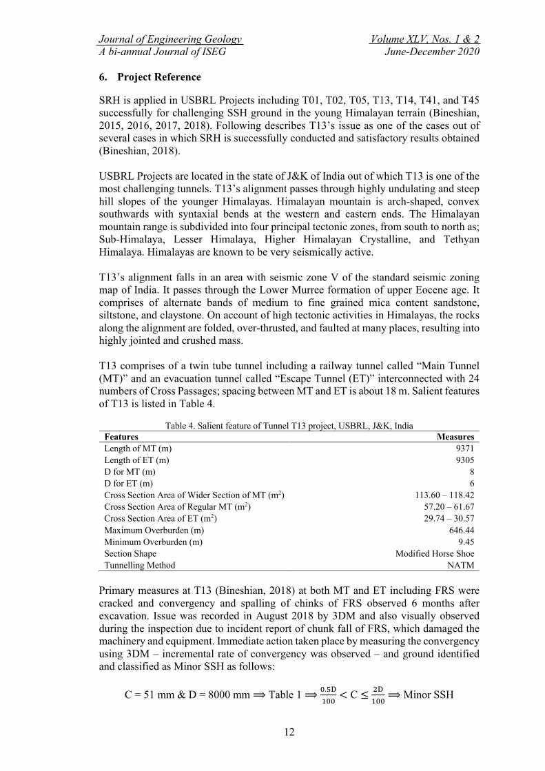
6. Project Reference SRH is applied in USBRL Projects including T01, T02, T05, T13, T14, T41, and T45 successfully for challenging SSH ground in the young Himalayan terrain (Bineshian, 2015, 2016, 2017, 2018). Following describes T13’s issue as one of the cases out of several cases in which SRH is successfully conducted and satisfactory results obtained (Bineshian, 2018). USBRL Projects are located in the state of J&K of India out of which T13 is one of the most challenging tunnels. T13’s alignment passes through highly undulating and steep hill slopes of the younger Himalayas. Himalayan mountain is arch-shaped, convex southwards with syntaxial bends at the western and eastern ends. The Himalayan mountain range is subdivided into four principal tectonic zones, from south to north as; Sub-Himalaya, Lesser Himalaya, Higher Himalayan Crystalline, and Tethyan Himalaya. Himalayas are known to be very seismically active. T13’s alignment falls in an area with seismic zone V of the standard seismic zoning map of India. It passes through the Lower Murree formation of upper Eocene age. It comprises of alternate bands of medium to fine grained mica content sandstone, siltstone, and claystone. On account of high tectonic activities in Himalayas, the rocks along the alignment are folded, over-thrusted, and faulted at many places, resulting into highly jointed and crushed mass. T13 comprises of a twin tube tunnel including a railway tunnel called “Main Tunnel (MT)” and an evacuation tunnel called “Escape Tunnel (ET)” interconnected with 24 numbers of Cross Passages; spacing between MT and ET is about 18 m. Salient features of T13 is listed in Table 4.
Table 4. Salient feature of Tunnel T13 project, USBRL, J&K, India
Features Measures Length of MT (m) 9371 Length of ET (m) 9305 D for MT (m) 8 D for ET (m) 6 Cross Section Area of Wider Section of MT (m2) 113.60 – 118.42 Cross Section Area of Regular MT (m2) 57.20 – 61.67 Cross Section Area of ET (m2) 29.74 – 30.57 Maximum Overburden (m) 646.44 Minimum Overburden (m) 9.45 Section Shape Modified Horse Shoe Tunnelling Method NATM
Primary measures at T13 (Bineshian, 2018) at both MT and ET including FRS were cracked and convergency and spalling of chinks of FRS observed 6 months after excavation. Issue was recorded in August 2018 by 3DM and also visually observed during the inspection due to incident report of chunk fall of FRS, which damaged the machinery and equipment. Immediate action taken place by measuring the convergency using 3DM – incremental rate of convergency was observed – and ground identified and classified as Minor SSH as follows:
C = 51 mm & D = 8000 mm ⟹ Table 1 ⟹ !.#$%!!
< C ≤ &$%!!
⟹ Minor SSH

Journal of Engineering Geology Volume XLV, Nos. 1 & 2 A bi-annual Journal of ISEG June-December 2020
13
Furthermore, ground was classified using I-System (Bineshian, 2019b) and Table 2 is used to derive the required instruction for treatment as follows:
Minor SSH and (I)-06 ⟹ Table 2 ⟹ Required Measures Instructions for treatment and rectification as required measures listed below;
- Scaling: Gentle removal of potentially hazardous spalling FRS, - Reaming: Rectification of the converged section to retain tunnel gauge and
obtain slightly larger cross section (Figure 1a), - FRS: Spraying a 100 mm thick FRS (as per (I)-06 according to I-System;
Bineshian, 2019a), - SRH: Application of Stage I for Minor SSH according to Figures 3a and 4a; a
systematic radially squared drilling pattern of 100 mm diameter holes with 6000 mm long at MT and 4000 mm long at ET with 2000 by 2000 mm spacing, and
- 3DM: Monitoring of 3DMS with spacing at 10 m with frequency of 1 reading per fortnight for 6 months (Table 3).
Immediately after application of SRH System, incremental rate of deformation approached to zero within a 30-day span and further convergency was terminated. After 6 months of observation and conduction of 3DM, no further crack generation/propagation observed. By application of the SRH System at T13, costly CYSS was avoided resulting saving in time and cost, obtaining reasonable safety, and achieving efficiency and performance in advancement. 7. Conclusions An empirical identification criterion as well as a classification system is proposed based on magnitude of convergency in SSH condition; Minor, Mild, and Severe-SSH (Table 1). Subsequently, required measures for treatment (Table 2) as well as a guideline for monitoring the condition is proposed for each class (Table 3). SRH System can be chosen for different SSH-Class; individually applied or combined with other SS. SRH is a system of squared pattern radially oriented drilled holes at periphery of tunnel that functions in control and treatment of SSH condition. It is invented based on a simple engineered concept; diversion/induction of incremental shear stresses and consequent convergence towards the empty holes at surrounding ground of tunnel instead of occurrence at periphery. Therefore, incremental procedure of SSH stresses is terminated and no further convergency is occurred at tunnel’s periphery. It is designed to eliminate/minimise the hazards and challenges involved with tunnelling under SSH condition as well as lessening the hindrance and cost caused by application of CYSS without compromising on safety. SRH System is verified through a long course of application in USBRL Projects since 2015. It is found to be an optimised (time- and cost-efficient and safe) YSS for tunnelling under SSH condition by minimising the hindrance and improving the advancement performance, removing/lessening the cost of CYSS material, and eliminating the hazards.
Journal of Engineering Geology Volume XLV, Nos. 1 & 2 A bi-annual Journal of ISEG June-December 2020
14
8. Future Research Recommendations Satisfactory and problem-solving results of a long-term research is provided in this paper; however, followings are suggested for further research, which may improve the outcome;
- Bearing in mind the fact that scale effect sensitivity is not directly considered in identification criterion and classification proposed for SSH condition in tunnels, it is recommended to conduct further research on the same.
- Suitable correlation was not achieved between the stress condition and convergency for development of an identification criterion using analytical approach; therefore, empirical approach and practical logics considered in development of the same that proposed for SSH in Table 1. It is recommended to scrutinise the proposed criteria in Table 1 with more data that can be obtained from further research conducted in practical cases of tunnelling under SSH condition.
- Figure 3 provides a schematic illustration for induced deformation inside the holes in SRH System. Further research on the observed patterns of induced deformation inside the free space of the holes using camera captured images or digital image correlations may reveal further facts about the mechanism/s of SSH behaviour and also it may yield a measuring technique for identification or prediction of SSH condition.
- SRH System is applied for burst prone ground; however, further data is required to develop it as an individual measure in treatment of burst prone ground.
9. Acknowledgement This paper and the successful verification of the research in practice would not have been possible without application in several projects since 2015; I thank Northern Railway (NR) and Konkan Railway Corporation Limited (KRCL) of Indian Railways for making it possible. I also thank Mr Debasis Barman, Deputy Project Consultancy Head at Amberg Engineering for his valuable feedback on proof reading of pre-final version of the paper. 10. References 1. Aydan Ö, Akagi T, Kawamoto, T 1993. ‘The squeezing potential of rock around tunnels: theory and
prediction’, Rock Mechanics and Rock Engineering, 2, l37 – 163.
2. Barla, G 1995. ‘Squeezing rocks in tunnels’, ISRM News Journal, Vol 2, No 3 & 4, 44 – 49. 3. Barla, G 2002. ‘Tunnelling under squeezing rock conditions’, Advances in Geotechnical
Engineering and Tunnelling 5, D Kolymbas Ed, 169 – 268.
4. Barla, G, Barla, M, Bonini, M, Debernardi, D 2014. ‘Guidelines for TBM tunnelling in squeezing conditions – a case study’, Géotechnique Letters, Vol 4, Issue 2, 83 – 87.
5. Bieniawski, Z T 1976. ‘Rock mass classification in rock engineering’, In Exploration for rock engineering, Proc of the Symp, ed Z T Bieniawski, 1, 97 – 106.
Journal of Engineering Geology Volume XLV, Nos. 1 & 2 A bi-annual Journal of ISEG June-December 2020
15
6. Bineshian, H 2011, ‘Failure and post-failure aspects of mechanical response of concrete structures to compression and tension’, MPhil Thesis, School of Civil Eng, The University of Western Australia, 133p.
7. Bineshian, H 2013, ‘Effects of stress non-uniformity on failure mechanisms of concrete/rocks’, PhD Dissertation, School of Civil Eng, The University of Western Australia, 319p.
8. Bineshian, H 2014, ‘Stress Non-uniformity in concrete and rock structures’, Lambert, Germany, 333p.
9. Bineshian, H 2015. ‘Instructions for treatment of squeezing at T01P1 CH31672’, Design Proposal, USBRL, KRCL.
10. Bineshian, H 2016. ‘Highly stressed zone; Treatment and rectification by application of SRH; T05 CH46595 – CH46695’, Design Documents; DDC Site Orders, USBRL, KRCL.
11. Bineshian, H 2017. ‘Plastic ground at T02 tunnel; Method of treatment using SRH’, DDC Project Register, USBRL, KRCL.
12. Bineshian, H 2018. ‘SRH; Treatment of squeezing ground at T13P01 and T13PA’, DDC Report and Instruction, USBRL, KRCL.
13. Bineshian, H 2019a. ‘I-System: A quick introduction’, The 8th IndoRock-2019 Conference, New Delhi, India.
14. Bineshian, H 2019b. ‘I-System: Index of Ground-Structure; A Comprehensive Indexing System for Ground-Structure Behaviour; Classification and Characterization’, Journal of Engineering Geology (JOEG), XLIV (1 & 2), 73 – 109, ISSN 0970 – 5317.
15. Bineshian, H 2020a. ‘I-System – Index of Ground-Structure; A Comprehensive Indexing System for Ground-Structure Behaviour’, DDAG-IRCON, (I & II), New Delhi, India.
16. Bineshian, H 2020b. ‘I-System: Index of Ground-Structure; Definition, Applications, and Utilisation in Design/Practice, TAI Journal, 9 (1): 42 – 64.
17. Choudhary, K, Bineshian, H, Gupta, S, Hegde, R K 2020. ‘Long range underground prediction of ground behaviour/hazards at tunnel T13’ Him Prabhat Journal.
18. Gioda, G 1982. ‘On the non-linear ‘squeezing’ effects around circular tunnels’, Int J Numerical Methods Geomech 6, 21 – 46.
19. Goel, R K, Jethwa, J L, Paithakan, A G 1995. ‘Tunnelling through the young Himalayas – a case history of the Maneri-Uttarkashi power tunnel’, Eng Geol, 39, 31 – 44.
20. Hoek, E 2001. ‘Big tunnels in bad rock’, ASCE Journal of Geotechnical and Geo-environmental Engineering, Terzaghi Lecture.
21. Hoek, E, Marinos, P 2000. ‘Predicting tunnel squeezing problems in weak heterogeneous rock masses’, Tunnels and Tunnelling International, 45 – 51: part one; 33 – 36: part two.
22. Hadjigeorgiou, J, Karampinos, E 2017. ‘Design tools for squeezing ground conditions in hard rock mines', in J Wesseloo (ed), Proceedings of the Eighth International Conference on Deep and High Stress Mining, Australian Centre for Geomechanics, Perth, 693 – 705.
23. Jethwa, J L, Singh, B, Singh, B 1984. ‘Estimation of ultimate rock pressure for tunnel linings under squeezing rock conditions – a new approach’ Design and Performance of Underground Excavations, ISRM Symposium, Cambridge, E T Brown and J A Hudson eds, 231 – 238.
24. Kovari, K 1998. ‘Tunnelbau in druckhaftem Gebirge - Tunnelling in squeezing rock’, Tunnel 5, 12 – 31.
Journal of Engineering Geology Volume XLV, Nos. 1 & 2 A bi-annual Journal of ISEG June-December 2020
16
25. Mata, M F 2018. ‘Tunnelling under squeezing conditions: Effect of the excavation method’, Civil Engineering, Université Paris-Est, 2018.
26. Schubert, W 1996. ‘Dealing with squeezing conditions in Alpine tunnels’, Rock Mech Rock Engng 29 (3), 145 – 153.
27. Selmer-Olsen, R, Palmström, A 1989. ‘Tunnel collapses in swelling clay zones’, Part 1, Tunnels and
Tunnelling, November 1989, 49 – 51.
28. Selmer-Olsen, R, Palmström A 1990. ‘Tunnel collapses in swelling clay zones’, Part 2, Tunnels and Tunnelling, January 1990, 55 – 58.
29. Shrestha, G L 2005. ‘Stress induced problems in Himalayan tunnels with special reference to
squeezing’, Doctoral thesis, Norwegian University of Science and Technology Faculty of Engineering Science and Technology Department of Geology and Mineral Resources Engineering.
30. Singh, B, Goel, R K 1999. ‘Rock mass classification: a practical approach in Civil Engineering’, Elsevier Science Ltd, UK.
31. Singh, B, Jethwa, J L, Dube, A K, Singh, B 1992. ‘Correlation between observed support pressure and rock mass quality’, Tunnelling and Underground Space Tech, 7, 59 – 74.
32. Terzaghi, K 1946. ‘Rock defects and loads in tunnel supports’, Rock tunnelling with steel supports. R V Proctor and T L White eds, The Commercial Shearing and Stamping Co, Youngstown, Ohio, 17 – 99.