SRC Ranger Converter 3000
51
iii
Transcript of SRC Ranger Converter 3000

iii

SRC Ranger Converter 3000
2
The information in this document may be trademarks or registered trademarks of their respective companies.
All rights reserved. Neither the whole nor any part of the information in this publication may be reproduced in any material form except with the written permission of S-Rain Control A/S.
This publication is intended only to assist the reader in the use of the Ranger Converter 3000. S-Rain Control A/S shall not be liable for any loss or damage arising from the use of any information in this publication, or any error or omission in such information, or any incorrect use of the product.
Address:
258-230-0003/A
iii
Contents Chapter 1. Introduction .................................................................................................................................................... 5
1.1. Target group ..................................................................................................................................................... 5 1.2. The Two-wire Technology .................................................................................................................................. 5 1.3. The Ranger Converter 3000 Extender ............................................................................................................. 5
Chapter 2. Technical Specifications ................................................................................................................................ 3 2.1. The Ranger Converter 3000 Board .................................................................................................................. 3
2.1.1. Expansion terminal ............................................................................................................................... 3 2.1.2. Output terminals ................................................................................................................................... 3 2.1.3. Station inputs ........................................................................................................................................ 4 2.1.4. Master Valve terminal ............................................................................................................................ 4 2.1.5. 24VAC supply........................................................................................................................................ 4 2.1.6. Common ............................................................................................................................................... 4 2.1.7. Two-wire terminals ................................................................................................................................ 5 2.1.8. Master valve activation ......................................................................................................................... 5 2.1.9. Flow input ............................................................................................................................................. 5 2.1.10. Decoder programming terminals ......................................................................................................... 5 2.1.11. Remote activation ................................................................................................................................ 5
2.3. The Ranger Converter 3000 Extender .............................................................................................................. 5 Chapter 3. System Installation ......................................................................................................................................... 7
3.1. Physical Installation .......................................................................................................................................... 7 3.1.1. Installing the Ranger Converter 3000 Board in the Cabinet ................................................................. 8 3.1.2. Connecting the Ranger Converter 3000 to 24VAC and Ground ........................................................... 9 3.1.3. Connecting the Master Valve .............................................................................................................. 10 3.1.4. Connecting the Main Controller Outputs to Ranger Converter 3000 Station Inputs ............................ 11 3.1.5. Connecting the Flow Input and Flow Output ...................................................................................... 12 3.1.6. Connecting the Load Output .............................................................................................................. 13 3.1.7. Connecting the Two-wire ..................................................................................................................... 14 3.1.8. Connecting Decoders for Programming ............................................................................................. 15 3.1.9. Connecting the Ranger Converter 3000 Extender to the Board.......................................................... 16
3.2. Ranger Converter 3000 Installation Diagram ................................................................................................. 17 Chapter 4. Operating the Ranger Converter 3000 ........................................................................................................ 18
4.1. The Display .................................................................................................................................................... 18 4.2. Buttons and LEDs .......................................................................................................................................... 18 4.3. Navigating the Menus of the Ranger Converter 3000 .................................................................................... 19
Chapter 5. Running the Ranger Converter 3000 ........................................................................................................... 20 5.1. The Main View ................................................................................................................................................ 20 5.2. Displaying Controller Status ........................................................................................................................... 21
5.2.1. Displaying the Flow Input ................................................................................................................... 21 5.2.2. Displaying the Number of Active Stations .......................................................................................... 21 5.2.3. Displaying the Alarm Status ................................................................................................................ 21
Chapter 6. Configuring the Ranger Converter 3000 ...................................................................................................... 25 6.1. Setting Up the Ranger Converter 3000 System ............................................................................................. 25 6.2. Programming Decoders ................................................................................................................................. 25 6.3. Setting the Master Valve Override .................................................................................................................. 26 6.4. Adjusting the Power Levels ............................................................................................................................ 26
6.4.1. Adjusting the Station Power ................................................................................................................ 27 6.4.2. Adjusting the Master Valve Power ....................................................................................................... 28 6.4.3. Resetting Station Power ..................................................................................................................... 28 6.4.4. Checking the Number of Active Stations ............................................................................................ 29
6.5. Resetting Data ................................................................................................................................................ 29 Chapter 7. Troubleshooting from the Ranger Converter 3000 ...................................................................................... 31
7.1. Testing Stations .............................................................................................................................................. 31 7.1.1. Testing Individual Stations .................................................................................................................. 31 7.1.2. Running the Electrical Test ................................................................................................................. 31

SRC Ranger Converter 3000
2
7.1.3. The Built-in Short Finding Test ............................................................................................................ 32 7.2. Testing the Two-wire Path ............................................................................................................................... 33 7.3. Increasing Station Power ............................................................................................................................... 34
Chapter 8. Troubleshooting in the Field ........................................................................................................................ 35 8.1. Checking Power and Current Readings ......................................................................................................... 35
8.1.1. Problems on the Two-wire ................................................................................................................... 37 8.2. Dealing with Unstable Stations ...................................................................................................................... 38 8.3. Dealing with Failing Stations .......................................................................................................................... 39
8.3.1. A Single Station Fails ......................................................................................................................... 39 8.3.2. Several Stations Fail ........................................................................................................................... 41
8.4. When there is a Short Circuit in the Field ...................................................................................................... 42 8.4.1. Using a Clampmeter ........................................................................................................................... 43 8.4.2. Locating the Short .............................................................................................................................. 43
Appendix A. Flashing new Firmware to the Ranger Converter 3000 System ............................................................... 47 A.1. Requirements ................................................................................................................................................. 47
A.1.1. Installing the USB driver ..................................................................................................................... 47 A.2. Flashing new Firmware to the Ranger Converter 3000 Board ....................................................................... 47 A.3. Flashing New Firmware to the Ranger Converter 3000 Extender ................................................................. 49

iv
Chapter 1. Introduction The Two-wire Decoder Interface (Ranger Converter 3000) is designed to integrate conventional systems with proven two-wire technology. The Ranger Converter 3000 allows clients in the landscape irrigation industry to retrofit their existing controllers systems. Not only does this provide a cost-efficient solution, it also ensures the clients' vendor independence by allowing them to use the main controller of their preferred choice. The Ranger Converter 3000 will enable any conventional irrigation system for the two-wire technology.
1.1. Target group This manual provides instructions intended for the setup and management of the Ranger Converter 3000 and therefore is primarily intended for installation and maintenance people.
1.2. The Two-wire Technology Once set up, the communication between the Ranger Converter 3000 system and the stations happen over a two-wire path. Depending on the signal from the controller, the stations each activate or deactivate a valve. Via the Ranger Converter 3000 board, the controller signals to the stations based on configurable schedules, eliminating the need for human interaction when the park, garden, or other surroundings need watering.
The Ranger Converter 3000 uses two-wire transmission technology to tell the stations when to act. This means that instead of laying out a cable to each individual valve, just one or two cables are laid out, and the stations all connect to the same cable(s).
The two-wire technology has several obvious advantages over a conventional system:
• Ease of installation: You are handling one roll of wire.
• Ease of expansion: When you need to add a station in the field, you don't have to dig in a new cable and
risk damaging the existing web of cables in the ground. You simply attach the new station to the existing cable.
• Cost reduction: You save money on expensive copper cable. Typically as much as 80 percent compared
to traditional cabling.
1.3. The Ranger Converter 3000 Extender The Ranger Converter 3000 system may be expanded with the Ranger Converter 3000 Extender - an interface board like the Ranger Converter 3000 itself but without the display and control panel. By adding the Ranger Converter 3000 Extender to your Ranger Converter 3000 system you may increase the capacity

The Ranger Converter 3000 Extender
2
with up to another 48 stations and an additional master valve. The master valve operates in parallel with the existing master valve input. The Ranger Converter 3000 Extender connects to the Ranger Converter 3000 system via the expansion terminal on the Ranger Converter 3000 board.
The Ranger Converter 3000 Extender is depicted in Chapter 2: Technical Specifications.
For information on connecting the Ranger Converter 3000 Extender to the Ranger Converter 3000 Board, turn to Chapter 3: System Installation.

3
Chapter 2. Technical Specifications
2.1. The Ranger Converter 3000 Board The core of your Ranger Converter 3000 system is the Ranger Converter 3000 Board that manages the integration between your main controller and the stations. In the sections below you will find a description of the layout of the Ranger Converter 3000 Board and its input and output terminals.
2.1.1. Expansion terminal Use the expansion terminal to connect the optional Ranger Converter 3000 Extender, enabling flow access for up to 48 additional stations and a master valve. For more information on connecting the Ranger Converter 3000 Extender and the Ranger Converter 3000 Board, turn to Section 3.1.9, “Connecting the Ranger Converter 3000 Extender to the Ranger Converter 3000 Board” [16].
2.1.2. Output terminals Use the output terminals to connect the flow output(s), and load.

4
Station inputs
Flow output Pulses are output at a frequency similar to the frequency that is read from the first sensor decoder. Maximum is 200 pulses / sec. The pulses are send with a 50/50% duty cycle.
Aux output
This is the same as Flow output, but for the second sensor decoder.
Alarm This relay is activated if any decoder is enabled. It can be used to connect a load (resistor or coil) if the controller requires a load.
2.1.3. Station inputs These inputs are used for connecting up to 48 stations in the conventional system to the Ranger Converter 3000. All inputs react on a 24VAC input. Use the following connection scheme:
Table 2.1. Station connection scheme (from left to right)
P1 Station 1 to Station 8 P2 Station 9 to Station 16 P3 Station 17 to Station 24 P4 Station 25 to Station 32 P5 Station 33 to Station 40 P6 Station 41 to Station 48
1) If the maximum number of simultaneous stations in the system are active, and one of the active stations is deactivated at the same time as a station with a higher number is activated, then the new station will not be activated.
2.1.4. Master Valve terminal Use this input terminal to connect the master valve. The HOT is the 24VAC from the mains transformer. For more information, turn to Section 3.1.3, “Connecting the Master Valve” [10].
2.1.5. 24VAC supply Use this input to connect to the power supply 24VAC 50/60 Hz. Power consumption is up to 2A (in addition to the main controller's electrical current. That is, the transformer must be rated at least 50 VA!). For more information, turn to Section 3.1.2, “Connecting the Ranger Converter 3000 to 24VAC and Ground” [9].
2.1.6. Common Use this input to connect to the main controller's common and GND rod. For more information, turn to Section 3.1.2, “Connecting the Ranger Converter 3000 to 24VAC and Ground” [9].
5
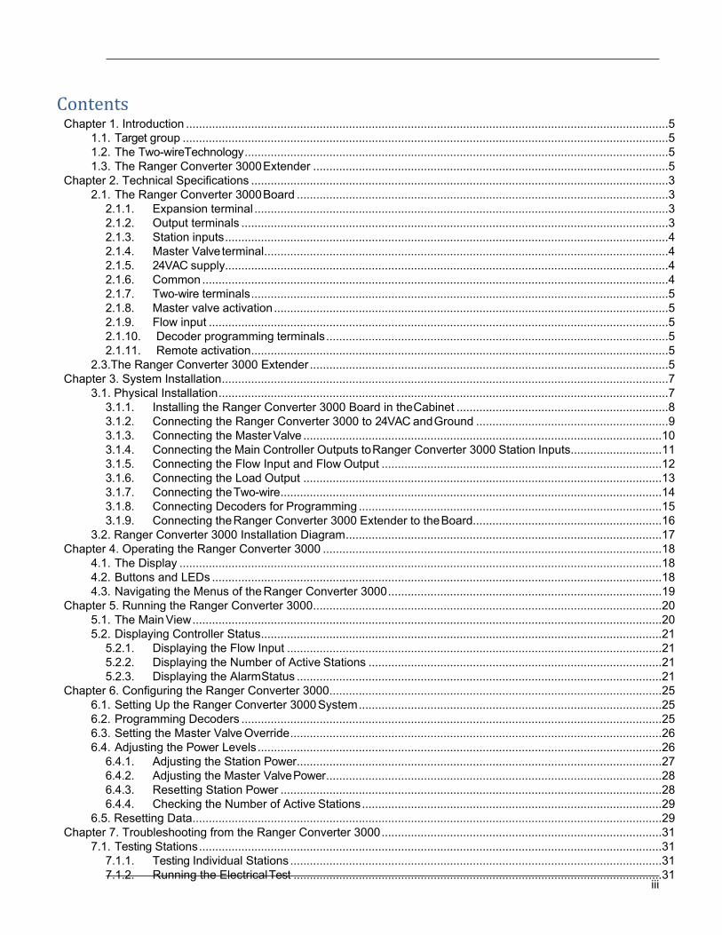
Two-wire terminals
2.1.7. Two-wire terminals LINE-1 and LINE-2 terminals are used for the actual two-wire connection. Each terminal is equipped with a switch for disconnecting the line during troubleshooting. For more information, turn to Section 3.1.7, “Connecting the Two-wire” [14].
Warning While the Ranger Converter 3000 is running, a short on the two-wire will not clear the display and thus it might still display active stations even if they are not active.
2.1.8. Master valve activation Use this terminal to connect a push button which may turn on the master valve when activated. This enables you to manually activate the master valve. When activated, the master valve will remain turned on for a specified number of hours. Pressing the push button quickly, when the master valve is on, will restart the timer. A longer push (more than 3 seconds) will stop the master valve. For more information, turn to Section 3.1.3, “Connecting the Master Valve” [10].
2.1.9. Flow input Input is not used. Instead flow is read via one or two sensor decoders on the 2-wire. These sensor decoders must have address 50000 and 50001 respectively.
2.1.10. Decoder programming terminals These terminals are used when programming decoders. All wires on the decoder must be connected. Blue wires to the left, white wires to the right. Section 3.1.8, “Connecting Decoders for Programming” [15].
2.1.11. Remote activation This feature is not implemented. Planned for a future release.
2.3. The Ranger Converter 3000 Extender The Ranger Converter 3000 Extender is like the Ranger Converter 3000 Board itself but without the the display and control panel. By adding the Ranger Converter 3000 Extender to your Ranger Converter 3000 system you may increase the capacity with up to another 48 stations and an additional master valve. The master valve operates in parallel with the existing master valve input. The Ranger Converter 3000 Extender connects to the Ranger Converter 3000 system via the expansion terminal on the Ranger Converter 3000 board.
For information on connecting the Ranger Converter 3000 Extender to the Ranger Converter 3000 Board, turn to Section 3.1.9, “Connecting the Ranger Converter 3000 Extender to the Ranger Converter 3000 Board” [16].
The Ranger Converter 3000 Extender
6

7
Chapter 3. System Installation This chapter provides information on connecting the various output and input terminals of your Ranger Converter 3000 system.
3.1. Physical Installation The physical installation of the Ranger Converter 3000 System involves the following procedures.
• Installing the Ranger Converter 3000 Board in the Cabinet
• Connecting the Ranger Converter 3000 to 24VAC and Ground
• Connecting the Master Valve
• Connecting the Main Controller Output to Ranger Converter 3000 Station Inputs
• Connecting the Flow Input and Flow Output
• Connecting the Alarm Output
• Connecting the Two-wire
• Connecting Decoders for Programming
• Connecting the Ranger Converter 3000 Extender to the Ranger Converter 3000 Board
In the following, each of these procedures are depicted in simple illustrations. Turn to the Ranger Converter 3000 Installation diagram at the end of this chapter for a full overview.

8
Installing the Ranger Converter 3000 Board in the Cabinet
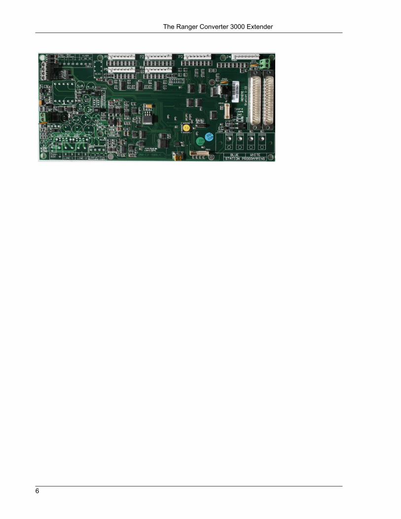
3.1.1. Installing the Ranger Converter 3000 Board in the Cabinet Depending on which main controller you use, installation may vary. Use four screws and a screwdriver to mount the board. Note that standoffs are typically required, which isolates the underside of the circuit board from the metal chassis. Ensure that the board is not shorted before applying power, or damage may occur. The photo below shows an example installation of a Ranger Converter 3000 with a typical controller. Please refer to the following sections for connecting the various terminals of the Ranger Converter 3000 Board.

9
Connecting the Ranger Converter 3000 to 24VAC and Ground
3.1.2. Connecting the Ranger Converter 3000 to 24VAC and Ground Using a flat head screwdriver connect the 24VAC terminals to the 120 V mains using a suitable transformer (supplied by the customer). Also, to help secure your system against lightning, you must ensure that the Ranger Converter 3000 is grounded. Refer to the illustration below and to the Ranger Converter 3000 Installation diagram at the end of this chapter.
Ranger Converter 3000 Board

10
Connecting the Master Valve
3.1.3. Connecting the Master Valve In terms of master valve connections, the Ranger Converter 3000 Board allows for the following:
• Connection of the master valve to the primary controller.
• Connection of a push button (supplied by the customer) for the manual activation of the master valve.
Using a flat screwdriver refer to the illustration below for master valve connections.
Ranger Converter 3000 Board

11
Connecting the Main Controller Outputs to Ranger Converter 3000 Station Inputs
3.1.4. Connecting the Main Controller Outputs to Ranger Converter 3000 Station Inputs
Using a flat head screwdriver, connect the main controller's outputs to the Ranger Converter 3000 station inputs. Refer to the illustration below and to the Ranger Converter 3000 Installation diagram at the end of this chapter.
Ranger Converter 3000 Board

12
Connecting the Flow Input and Flow Output
3.1.5. Connecting the Flow Input and Flow Output Using a flat head screwdriver, connect the flow output. Input is not used. Instead flow is read via one or two sensor decoders on the 2-wire. These sensor decoders must have address 50000 and 50001 respectively. Refer to the illustration below and to the Ranger Converter 3000 Installation diagram at the end of this chapter.
Ranger Converter 3000 Board

13
Connecting the Alarm Output
3.1.6. Connecting the Load Output Using a flat head screwdriver, refer to the illustration below and to the Ranger Converter 3000 Installation diagram at the end of this chapter for information on connecting the load output.
Flow Output: outputs the same frequency as sensor decoder 1.
Aux Output: outputs the same frequency as sensor decoder 2.
ALARM: controls dynamic load.
Ranger Converter 3000 Board

14
Connecting the Two-wire
3.1.7. Connecting the Two-wire Using a flat head screwdriver, connect the two-wire by fastening it to the two-wire terminals (Line 1 and/or Line 2). A and B are required on each 2-wire. Refer to the illustration below and to the Ranger Converter 3000 Installation diagram at the end of this chapter.
Important It is necessary to protect the two-wire against lightning by adding an LSP-100 for every 150 meter. The LSP should be grounded via a ground rod with less than 50 ohms.
Note that Line 1 and Line 2 are parallel terminals. This enables you to split the two-wire in two parts, using Line 1 for one part of the installation and Line 2 for the other.
The switches located above Line 1 and Line 2 may be set to either On or Off thereby activating or deactivating the two-wire. Each switch should be set to On when the installation is up and running. Set the switch to Off, for instance, during troubleshooting a short in the installation. This is a quick way to exclude either one of the two-wires. On is to the right, Off is to the left.
Ranger Converter 3000 Board

15
Connecting Decoders for Programming
3.1.8. Connecting Decoders for Programming Use the Station Programming terminals to the right on the Ranger Converter 3000 Board when connecting the decoder for programming. Connect the two-wire by fastening it to the terminals labelled Blue and White, respectively. Refer to the illustration below and to the Ranger Converter 3000 Installation diagram at the end of this chapter.
Once connected, you can assign an address to the decoder from the Ranger Converter 3000 panel. You can also test that the decoder is fully functional. For information on programming and testing decoders turn to Chapter 6: Configuring the Ranger Converter 3000.
Ranger Converter 3000 Board

16
Connecting the Ranger Converter 3000 Extender to the Board
3.1.9. Connecting the Ranger Converter 3000 Extender to the Board Use the expansion terminal to connect the optional Ranger Converter 3000 Extender to the Ranger Converter 3000 Board enabling the expansion of up to 48 additional stations and a master valve.
Using a flat head screwdriver connect the wires as follows:
• Terminal 1 on the Ranger Converter 3000 Board connects to terminal 2 on the Ranger Converter 3000 Extender
Board.
• Terminal 2 on the Ranger Converter 3000 Board connects to terminal 1 on the Ranger Converter 3000 Extender Board.
• Terminal 3 on the Ranger Converter 3000 Board connects to terminal 3 on the Ranger Converter 3000 Extender
Board.
• Terminal 4 on the Ranger Converter 3000 Board connects to terminal 4 on the Ranger Converter 3000 Extender Board.
Note that terminal 1 is towards the top of the board. Also refer to the illustration below when connecting the Ranger Converter 3000 Extender.
Ranger Converter 3000 Board
Ranger Converter 3000 Extender Board
17
Ranger Converter 3000 Installation Diagram
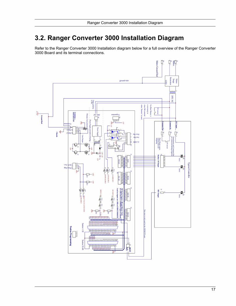
3.2. Ranger Converter 3000 Installation Diagram Refer to the Ranger Converter 3000 Installation diagram below for a full overview of the Ranger Converter 3000 Board and its terminal connections.
18
Navigating the Menus of the TDI
Chapter 4. Operating the Ranger Converter 3000 This section presents the display and the controls on the Ranger Converter 3000.
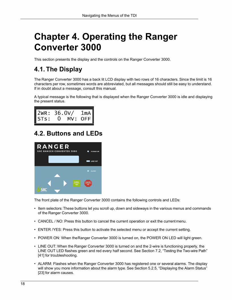
4.1. The Display The Ranger Converter 3000 has a back lit LCD display with two rows of 16 characters. Since the limit is 16 characters per row, sometimes words are abbreviated, but all messages should still be easy to understand. If in doubt about a message, consult this manual.
A typical message is the following that is displayed when the Ranger Converter 3000 is idle and displaying the present status.
4.2. Buttons and LEDs
The front plate of the Ranger Converter 3000 contains the following controls and LEDs:
• Item selectors: These buttons let you scroll up, down and sideways in the various menus and commands of the Ranger Converter 3000.
• CANCEL / NO: Press this button to cancel the current operation or exit the current menu.
• ENTER / YES: Press this button to activate the selected menu or accept the current setting.
• POWER ON: When the Ranger Converter 3000 is turned on, the POWER ON LED will light green.
• LINE OUT: When the Ranger Converter 3000 is turned on and the 2-wire is functioning properly, the
LINE OUT LED flashes green and red every half second. See Section 7.2, “Testing the Two-wire Path” [41] for troubleshooting.
• ALARM: Flashes when the Ranger Converter 3000 has registered one or several alarms. The display
will show you more information about the alarm type. See Section 5.2.5, “Displaying the Alarm Status” [23] for alarm causes.

19
4.3. Navigating the Menus of the Ranger Converter 3000 1. Use the item selectors to toggle (move right and left) and scroll (move up and down) through the menus
of Ranger Converter 3000.
2. In case more than one option is available in a particular menu or view, you will see Up and Down arrows. Use the item selectors to scroll through the options. The * sign next to a command indicates that the command is selectable. To select the option, press ENTER.

20
Navigating the Menus of the TDI
Chapter 5. Running the Ranger Converter 3000 This chapter contains information how to run the Ranger Converter 3000 once it
has been set up. Read more about:
• The main view
• Displaying controller status
5.1. The Main View The main view is the active view when the system is up and running. Use the main view to get an overview of the overall status of the two-wire. In case of alarm(s), the display will alternate between the normal display and the display of each alarm.
1. Power up the Ranger Converter 3000. For a few seconds the current firmware information and the
Ranger Converter 3000 number shows on the screen. While the Ranger Converter 3000 is turned on, the POWER ON LED will light green, and the LINE OUT LED will flash red/green every ½ second.
2. The main view displays.
Note Except when you work in the submenus, the Ranger Converter 3000 will revert to the main view after 10 seconds with no panel activity.
The top line of the main view shows the voltage and mA measured on the two-wire. The voltage should show 32V to 36V on a 2-wire with no decoders installed, and the mA should be close to 0 mA. On a 2-wire with decoders installed (but not running), the mA should show approximately 0.5 mA per decoder.
The bottom line shows the total number of active stations (i.e. decoders) and the status of the master valve (MV), i.e., if it is turned on or off.
For active decoders, the mA depends on the power level. The more power you assign, the less number of simultaneous active stations is possible. For more information turn to Adjusting the Power Levels.

21
Each decoder uses about 0.5 mA in idle mode. For instance, if your system includes 50 decoders, the mA value should total 25 mA with no activity. If the mA value is suddenly significantly higher, for instance 200 mA, then something is wrong: This could indicate a ground leak. For more information, turn to Chapter 8: Troubleshooting in the Field.
5.2. Displaying Controller Status Five different types of statuses are available:
• Flow input
• Status of active stations
• Alarm status
5.2.1. Displaying the Flow Input The current flow input on the system can be seen from the Flow Input view. This view expresses the current flow in pulses per seconds (in Hz).
To display the flow input:
1. In the Main view, use the item selectors to scroll sideways to the Flow Input view.
5.2.2. Displaying the Number of Active Stations The Active Stations views shows the number of active stations, master valves and pumps. The view also displays the names of the active stations.
1. In the Main view, use the item selectors to scroll sideways to the Active Stations view.
2. If more stations are active, use the item selectors to scroll to the other active stations.
If no stations are running, this view will not display anything.
5.2.3. Displaying the Alarm Status When the ALARM LED on the Ranger Converter 3000 panel indicates that one or more alarms have been detected, proceed to the Alarm Status view to get an overview and determine what action to take.

Displaying the Alarm Status
24
Note For each alarm type you may set the reaction type. For more information, turn to Section 6.5, “Setting Up FloGuard” [31].
To display the alarm status:
1. In the Main view, use the item selectors to scroll sideways to the Alarm Status view.
2. Use the item selectors to scroll through the alarms, and check whether the status is Passive, Active or
Pas Clr?. The Pas Clr? option indicates that at some point an alarm was detected, but that it is no longer active.
The Alarm Status view may display the following alarm types:
Sht 2-wire short alarm. The alarm stays on as long as there is a short in your system. You can clear the
notification by viewing the alarm list.MST
Max active stations reached. This means that a program tried to start a station when the maximum number of stations was already running. The alarm will be cleared once you have viewed the alarm list and acknowledged the alarm.
P2Q Indicates whether the quality of the 2-wire has dropped to a level where the SRC RANGER CONVERTER 3000 cannot read the sensor decoder, for example due to leak to ground, bad connections etc.

25
Setting the Master Valve Override
Chapter 6. Configuring the Ranger Converter 3000 6.1. Setting Up the Ranger Converter 3000 System All set-up is done by using the menus and commands accessible from the Main menu.
When setting up the Ranger Converter 3000 system, we recommend you use the following
sequence:
1. Programming Decoders
2. Setting the Master Valve Override
3. Adjusting the Power Levels
4. Resetting your Configuration Data
6.2. Programming Decoders When programming decoders you perform two actions for each decoder:
1. Assign a unique ID to the decoder.
2. Test the decoder.
To program a decoder:
1. Connect the decoder’s white and blue wires to the sockets labelled White and Blue on the Ranger
Converter 3000.
2. Scroll sideways to the Main menu, then scroll to the Dec Program menu, and press ENTER.
3. If you did not already connect the decoder, you will be prompted to do so at this point. Once it is connected, press ENTER.
4. Scroll to the Change ID menu to open the Choose ID window.
5. Scroll through the IDs (ST1, ST2, ST3, etc). Press ENTER two times to confirm your selection.
26
Adjusting the Master Valve Power
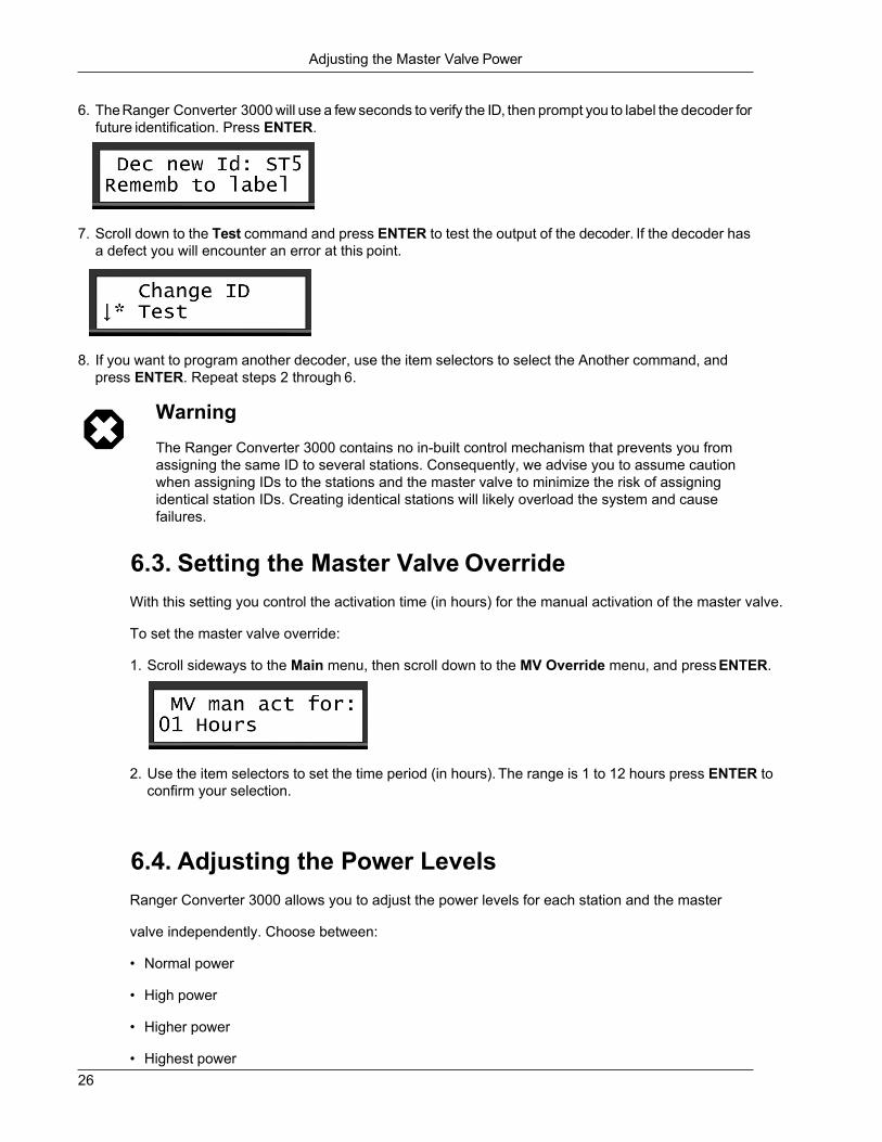
6. The Ranger Converter 3000 will use a few seconds to verify the ID, then prompt you to label the decoder for future identification. Press ENTER.
7. Scroll down to the Test command and press ENTER to test the output of the decoder. If the decoder has
a defect you will encounter an error at this point.
8. If you want to program another decoder, use the item selectors to select the Another command, and
press ENTER. Repeat steps 2 through 6.
Warning The Ranger Converter 3000 contains no in-built control mechanism that prevents you from assigning the same ID to several stations. Consequently, we advise you to assume caution when assigning IDs to the stations and the master valve to minimize the risk of assigning identical station IDs. Creating identical stations will likely overload the system and cause failures.
6.3. Setting the Master Valve Override With this setting you control the activation time (in hours) for the manual activation of the master valve.
To set the master valve override:
1. Scroll sideways to the Main menu, then scroll down to the MV Override menu, and press ENTER.
2. Use the item selectors to set the time period (in hours). The range is 1 to 12 hours press ENTER to
confirm your selection.
6.4. Adjusting the Power Levels Ranger Converter 3000 allows you to adjust the power levels for each station and the master
valve independently. Choose between:
• Normal power
• High power
• Higher power
• Highest power

27
Setting the Master Valve Override
For most systems, Normal power is sufficient. Within agricultural systems, however, you may find stations and valves that need more power.
Important Increasing the power levels for your stations mean that fewer stations may be active at a time. Ranger Converter 3000 lets you supervise the impact. For more information turn to the section "Checking the Number of Active Stations" later in this chapter.
6.4.1. Adjusting the Station Power To adjust the power levels for your stations:
1. Scroll sideways to the Main menu, then scroll down to the Power Levels menu, and press ENTER.

28
Adjusting the Master Valve Power
2. Scroll down to the ST Power command, and press ENTER.
3. Choose between Normal power, High power, Higher power and Highest power.
4. Press ENTER to confirm you selection.
6.4.2. Adjusting the Master Valve Power To adjust the power levels for the master valve:
1. Scroll sideways to the Main menu then scroll down to the Power Levels menu, and press ENTER.
2. Scroll down to the MV Power command, and press ENTER.
3. Choose between Normal power, High power, Higher power and Highest power.
4. Press ENTER to confirm you selection.
6.4.3. Resetting Station Power In case you want to reset the station power to the factory settings, please use the reset command.
1. Scroll sideways to the Main menu, then scroll down to the Power Levels menu, and press ENTER.
2. Scroll down to the Default reset command, and press ENTER.

29
Checking the Number of Active Stations
3. Press ENTER to confirm.
6.4.4. Checking the Number of Active Stations Increasing the power levels for your stations mean that fewer stations in your system may be simultaneously active. The Ranger Converter 3000 lets you supervise the impact of changing these settings.
To check the number of active stations:
1. Scroll sideways to the Main menu, then scroll down to the Power Levels menu, and press ENTER.
2. Scroll down to the Show max act command, and press ENTER.
The screen will show you the maximum number of stations that can be active at the same time, in this case 10.
6.5. Resetting Data In rare cases, it may be necessary to reset the data.
To reset you data:

30
Resetting Data
1. Scroll sideways to the Main menu, then scroll down to the Data Reset menu, and press ENTER.
2. Press ENTER again to confirm you want to reset your configuration data.

31
Chapter 7. Troubleshooting from the Ranger Converter 3000 7.1. Testing Stations This section describes the various ways you can troubleshoot your stations from the Ranger Converter 3000.
7.1.1. Testing Individual Stations There are two ways to test if a single station is working correctly:
1. If you don't have access to the station - maybe it's buried in the landscape - you can run the test program
(see Section 7.1.2, “Running the Electrical Test” [39]).
2. If you have physical access to the station, you can detach it from the two-wire, take it to the Ranger Converter 3000, and perform a station test by connecting the decoder to the STATION PROGRAMMING terminals. The display will then inform you of the status. Refer to Section 3.1.8, “Connecting Decoders for Programming” [15].
If this test fails, the station must be replaced.
7.1.2. Running the Electrical Test The Ranger Converter 3000 has a built-in test that will activate each station in turn for just one second in order to check if they are responding correctly. The stations must be connected to the solenoids that activate valves in the landscape, and the test can tell whether the stations and solenoids are working correctly in conjunction.
Procedure 7.1. Running the station test
1. Scroll sideways to the Main menu, then scroll down to the Tests menu, and press ENTER.
2. Scroll down to the ST Electrical command, and press ENTER.
Now you'll be prompted to select the station you wish to start from:

The Built-in Short Finding Test
32
3. Use the item selectors to select a station and push the ENTER button to start the test.
The screen will either confirm that the test went OK or it failed.
In addition to this basic information, three values are displayed: The Before current mA, the Inrush current mA and the Holding current mA:
• Before current: Shows the current just before the station is activated.
• Inrush current: Shows the current in the "inrush" period, which is the short period when the station
activates the decoder. In this case, the station pulled a current of 400mA.
• Holding current: Shows the current level after the decoder was open, in this case 33mA
Numbers in this range are normal. The Before current corresponds to the number of stations multiplied by 0,5 mA. In this case, there are 16 decoders in the system which amounts to 8mA. As for the Inrush current it takes a larger charge in the "inrush" period to pull the solenoid open, and then a smaller current (the Holding current) to keep it open afterwards. Typically, the Holding current is approximately 25mA higher than the Before current, in this case 33mA.
If the station fails, the display will look something like this:
In this case, there was no response from the station.
Regardless of whether the station fails or turns out OK, you move on to testing the next station in line
by pushing the ENTER button.
7.1.3. The Built-in Short Finding Test If you suspect your system has a short somewhere in the field, use the built-in short test in the Ranger Converter 3000. This test won't tell you anything you can't already see if you've configured the controller to display voltage and current in the display, but it's the first step in the troubleshooting process.

33
Testing the Two-wire Path
Procedure 7.2. Running the short finding test
1. Scroll sideways to the Main menu, then scroll down to the Tests menu, and press ENTER.
2. Scroll down to the Short Finding command, and press ENTER.
3. Inspect the measurements in the display:
• If the two-wire is OK, the voltage will be relatively high (34-36V), and the current (mA) relatively low.
In a test setup this is what it looked like:
The voltage is 36V and the current is 0mA.
In addition, both Red and Green Line Out LEDs will be lit.
• If there is a short somewhere in the system, you'll usually see a relatively high current and lower voltage instead:
Now the voltage is 0V and the current is 229mA - something is causing the system to "eat up" a lot of current.
In addition, if the voltage is very low, the Line Out LEDs will both be out.
• If the voltage is just slightly lower than normal (31-35V), consult the table in Section 8.1, “Checking
Power and Current Readings” [43].
If you find that there's a short in your system, you should try to locate it, using a clampmeter. (See Section 8.4.1, “Using a Clampmeter” [51]).
7.2. Testing the Two-wire Path The first indication that you might have a short or a fault somewhere on the two-wire path is that the Line Out indicators (the green and red LEDs on the Ranger Converter 3000) will flicker very quickly, or be not lit at all.
If the Ranger Converter 3000 senses an electrical leak somewhere, the two-wire path will change to 50Hz mode, meaning that the LEDs may both be lit . After a while you'll see an indication in the lower part of the display that a short occurred.
If the leak is severe (current more than 600-650mA), the LEDs will turn off due to the loss of power. However, current will still be running on the two-wire.

Increasing Station Power
34
There are two stages of testing the two-wire for shorts: you can run a built-in short test from the Ranger Converter 3000, and if something seems wrong, you can inspect the two-wire in the field, using a clampmeter.
7.3. Increasing Station Power In case the stations are not giving out enough power for the valves or pumps to pull open, it is possible to increase the power.
Note Do not simply increase station power because the valves are not opening. First verify the integrity of the 2-wire. If the current is too high, then you must fix that problem.
Important Increasing the station power means that fewer stations can run simultaneously (less than 10). When changing the power setting you can see how may stations can be run at the same time. For example, when changing the power setting for regular valves to "Highest Power" you can run a maximum of five simultaneous valves.

35
Chapter 8. Troubleshooting in the Field You discover problems with the installation in the field in a number of ways. The following four sections walk you through how to deal with the most frequent scenarios.
8.1. Checking Power and Current Readings In a healthy system you should see power and current readings for the two-wire path along these lines:
Idling Heavy Usage (many stations
running) Power 33-36V 31-34V Current 0-3mA (no stations attached) 300-600mA
Tip See Section 7.2, “Testing the Two-wire Path” [41] for instructions on how to do power and current readings in the display of the Ranger Converter 3000.
Tip When the Ranger Converter 3000 shows high current readings, always first disconnect two-wire at the Ranger Converter 3000. Use the switches to do so (refer to Section 3.1.7, “Connecting the Two-wire” [14]). If the high current disappears, the two-wire is the problem. If the high current remains, the Ranger Converter 3000 has the fault.
To get a more precise idea of how your current reading should be, you should add the standby usage and the usage for any running units, using these rules of thumb:
Standby Usage
When no valves are running, all connected stations will consume around 0.5mA each. This is not an exact number and will vary by 20-30 percent in each direction - it's normal to see idle consumption in the 0.4- 0.65mA range.
So, for example, 20 connected stations will consume around 8-13mA, and 100 units will consume some 40-65mA. Note that this will be true even if there is nothing connected to the white (output) wires of the decoder. Each decoder all by itself draws 0,5 mA.
Active Stations
When active, any station, controlling a valve or master valve, will consume around 15 - 35mA.
This means that when running just one station or a master valve on a system with 96 connected units, you may use around 115-140mA.
Note These numbers are valid for an running with normal power settings - if you change the power settings (as described in ???) the numbers will change - the higher power settings, the higher current readings.
Here are a couple of practical scenarios and how to deal with them:

36
Checking Power and Current Readings
If the power reading is below 25V The field installation is consuming so much power that the Ranger Converter 3000 has lowered the power on the two-wire, and you should go locate the problem in the field (See Section 8.4, “When there is a Short Circuit in the Field” [50]).
Note The current reading can be "normal" in this situation (350-600mA or lower) - this is one of the Ranger Converter 3000's safety features.
If the power reading is between 25V and 31V
This is abnormal. The Ranger Converter 3000 will keep running normally, but there's a probability you have a short somewhere - you should go locate the problem in the field (See (See Section 8.4, “When there is a Short Circuit in the Field” [50])).
If the power reading is between 31V and 35V when no stations are running
In this range you must inspect the current to estimate the health of your system.
The following table tries to give you an idea of whether or not your system is behaving as expected. You calculate the expected current as 0.5mA x <number of stations>. Though no station consumes exactly 0.5mA, the figures average out the more stations you have connected to your system.
Important Troubleshooting is not an exact science and this is not matrix for exactly determining the health of your system. This table can help point you in the right direction though.

37
Problems on the Two-wire
Table 8.1. Scenarios with power readings between 31V and 35V
Current Current could be in these ranges depending on
the number of connected stations: State
20 40 60 80 96 Low current
(Less than -15%)
< 9mA < 17mA < 25mA < 34mA < 42mA It is possible that one or more stations are not connected correctly. Try running the test program (See Section 7.1.2, “Running the Electrical Test” [39]).
Normal current (-15% - +20%)
9-12mA 17-24mA 25-36mA 34-48mA 42-60mA Everything is fine - the system is looking healthy.
High current
(+20% - +50%)
12-15mA 24-30mA 36-45mA 48-60mA 60-75mA You might have a problem somewhere on the two-wire causing an excess consumption. The Ranger Converter 3000 can handle this, but you could be looking at problems that dramatically increase under wetter conditions. See Section 8.1.1, “Problems on the Two-wire” [45].
Excessive current
(More than +50%)
> 15mA > 30mA > 45mA > 60mA > 75mA This is a risky situation that can interfere with the functionality of the Ranger Converter 3000, and you should locate the problem in the field right away. It will typically be a bad connection or a cable left open-ended in the field. Troubleshooting is identical to when locating short circuits in the field (see (See Section 8.4, “When there is a Short Circuit in the Field” [50])), but the current will not be as excessive as when a short occurs.
8.1.1. Problems on the Two-wire It only takes seemingly innocent cracks in the cable insulation or connections to cause big problems: If you remove the insulation on just 1/3 of an inch on a AWG14 cable (both wires) and immerse the cable in water the current can increase by 30mA. If you immerse into salt water the current increases by as much as 170mA.

38
Dealing with Unstable Stations
Obviously this means that just a handful of minor cracks in the insulation can add up to a substantial increase in the current reading, and the problem in detecting these kinds of problems is that they seem to come and go, depending on how wet the soil is.
8.2. Dealing with Unstable Stations If a station seems to fail randomly, typical reasons include:
• You have increased the power used to activate stations (See ???). This means that you need to lower
the number of simultaneously running stations, or all stations might not work as intended, giving a seemingly random problem depending on which schedule you are running.
• There are leaks in the insulation on your two-wire - when the soil is dry everything works just fine, but
when it gets more moist, stations seem to fall out randomly. See the previous section for more details.
• In case you have a loop installation, problems may occur if the loop is broken, as the resistance between a station and the Ranger Converter 3000 can increase, pushing up the power consumption:
Note We do no recommend using loops since troubleshooting these can be a complex process.
Normal Loop Loop Broken
The resistance between the station and the Ranger Converter 3000 is 0.75*R
The resistance between the station and Ranger Converter 3000 the is 3*R
To find out whether your loop is broken, follow this procedure:
1. Open the loop in one end - if the loop goes all the way back to the Ranger Converter 3000, just detach one of the two-wires on the controller.

39
Dealing with Failing Stations
2. Perform an "electrical test" as described in "Running the Electrical Test" in Chapter 7: Troubleshooting
from the Ranger Converter 3000. This will activate each in turn - if you see stations failing, chances are that they are on a stretch of the two-wire that has been orphaned by a break of the loop in the field.
3. If everything is still OK, close the loop and open it in the other (detach the opposite two-wire of the
one you just tried) end and re-run the test.
If the same stations keep failing, you should look at the instructions in the following section "Dealing with Failing Stations".
8.3. Dealing with Failing Stations More often than not, what seems to be a faulty station is really a problem on the two-wire between the station and the Ranger Converter 3000, since this is the most vulnerable part of your system.
The approach to troubleshooting failing stations vary a bit depending on whether you just have one, or several failures - the following two sections talk about each scenario.
8.3.1. A Single Station Fails If the failing station has just been installed, did you remember to assign an ID to the decoder?
If the failing station has been known to work, perform the electrical test (See Section 7.1.2, “Running the Electrical Test” [39])) on the station in question and follow these guidelines:
If there's little or no reaction from the stations 1. Go to the station in the field and perform these
tests:
• Check wires and connections between the two-wire, the station and the solenoid (see figure on next page).
• Short circuit the two-wire at the station and use
a clampmeter (see Section 8.4.1, “Using a Clampmeter” [51]) to check if power is still OK. In this case, the current should be > 200 mA. Iif this is the case, the problem is in the station or solenoid, and not on the two-wire between the station and the Ranger Converter 3000 (see figure on next page).
• Detach the solenoid and measure the resistance
of the solenoid itself. Compare this to another solenoid of the same type (the resistance is typically 20-60 ohms.) If the resistance is significantly higher, try replacing it.
Note Some solenoids come with a diode on one of the wires. This means that the solenoid is polarized and the connection of the white wires from the decoder to the solenoid is

40
A Single Station Fails
significant. Thus you can try to swap the two wires around and see if it makes a difference.
The wires to polarized solenoids will be different from each other. They may be red and black, or might have a white stripe. If the two solenoid's wires are different, always try swapping their connections to the decoder..
• Take the station to the Ranger Converter 3000 and perform a direct test before replacing it.
If the station fails with too high current reading • Check the two-wire between the solenoid and the station for cracks in the insulation or bad connections.
• Detach the solenoid from the station and measure
the resistance of the solenoid itself. If the resistance is less than expected, it might be damaged by lightning or it might have a short circuit. Try replacing the solenoid.
• Take the station to the controller and perform a
direct test before replacing it.
Figure 8.1. Checking Connections

41
Several Stations Fail
Figure 8.2. Testing the path to a station
8.3.2. Several Stations Fail Here is a checklist if multiple stations fail:
• If two stations are configured with identical IDs you can get a rather confusing behavior in the system.
Imagine the following scenario:
• We consider two stations, M and N.
• You have configured station M to have the ID "ST20".
• Station N should have been called "ST21", but by mistake you configured this to be "ST20" as well.
When you: The following happens: Because: Try to activate "ST20" M and/or N might fail to open. Since both stations think they're
"ST20", they'll both try to open. If you're lucky, there's enough current on the two-wire to pull open both, but depending on the current and the resistance in the solenoids, one or both can fail to open.
Try to activate "ST21" Both M and N fail to open. None of the stations react to "ST21" since they both think they are "ST20."
• If you're dealing with a new installation, and the failing stations seem to be spread randomly in the field,
you could be looking at solenoids with built-in diodes - on this type of solenoid it is significant which one of the wires in the cables are connected to what (see previous section "A Single Station Fails" for more details).
• If the failing stations are located on the same dead end branch of your two-wire, chances are that the
connection to the branch is faulty. If all stations from a point on a branch and outwards fail (stations 9 and 10 in the illustration below), measure the connection to each station - using a clampmeter - until you reach the point of failure. For more information turn to see Section 8.4.1, “Using a Clampmeter” [51].

42
When there is a Short Circuit in the Field
Figure 8.3. Checking a branch
If all connections seem OK, the two-wire itself might be damaged. Things to look for along the two-wire:
• Any signs of digging in the ground? Wild animals and staff under equal suspicion here.
• Has any other kind of machinery been at work and unknowingly penetrated the two-wire?
• Check all transitions where the cable runs from underground to over ground, from soil to pipes etc.
Important If you replace a stretch of the two-wire, make sure to remove the old part completely (disconnect all connections), as the old piece of cable might interfere with the current in the new cable.
8.4. When there is a Short Circuit in the Field A "clean" short circuit in the field - direct connection between the two wires in the two-wire path with zero Ohms resistance - will cause the Ranger Converter 3000 to display a warning. In addition to the warning, you'll see that the Line Out LED is constantly lit instead of blinking as it normally does. If the short is very severe the Line Out LED may stop working all together.
But you can't always be sure that the Ranger Converter 3000 will be able to detect a short circuit in the field - if the short is in the far end of the cabling, the controller may just experience it as heavy usage. However, the current reading will always reveal a short as the current will be significantly higher than normal. (Could exceed the expected value with 100mA or more.)
Typically, a short circuit in the field is either a problem with the two-wire itself (cracks in the insulation, bad connections etc.) or consequences of lightning striking the system, damaging stations, solenoids or other electronics attached to the two-wire.

Using a Clampmeter
43
8.4.1. Using a Clampmeter In order to locate a short you can use a clampmeter. You need physical access to the two-wire, or at least parts of it, since the clampmeter directly measures on the individual wires in the cable.
Procedure 8.1. Using a clampmeter for short finding
1. Run a short test on the Ranger Converter 3000.
2. Set the clampmeter to "50 Hz mode" or equivalent. Setting it to "Wide Range" or similar modes might not work out.
3. Now start measuring the two-wire from the controller and out. You measure the two-wire by placing the
clampmeter around one of the wires in the two-wire path. Now measure the other one. Always measure both wires separately. Sometimes one wire will have a problem and the other will be OK.
When the measurement on the clampmeter is substantially lower than what you see in the controller display, you've passed the point of the short.
8.4.2. Locating the Short Before trying to locate the short in your system, make sure you have the following:
• Clampmeter.
• An "as-built" drawing (or equivalent knowledge) of the cable layout for the two-wire path. Notably you
need to know of all branches and loops.
The overall rule of thumb when looking for a short is that the current will move from the controller directly to the short and back. This means that you can "follow the current" and eventually be led to the short:
Figure 8.4. Faulty station
Note If your installation loops back to the Ranger Converter 3000 you must open the loop, or you won't know which way the current is running around the loop and troubleshooting will be almost impossible.
Note We do not recommend using loops since troubleshooting these can be a complex process.
Locating the Short
44
Troubleshooting falls into three phases and the following three procedures explain how you should go about locating the problem. Walking through each procedure in turn should ensure efficient troubleshooting.
Procedure 8.2. Phase I: Checking for Problems at the Controller
1. Measure the current at the point where the two-wire path is connected to the controller. Measure both wires in the two-wire path separately, one at a time. Make a note of your readings as you'll use these for comparison if you need to locate a faulty branch in the field.
• If one of the cables connected to the Ranger Converter 3000 loops back to the controller, you must
open the loop before measuring.
• If more than one non-looped cable is connected to the Ranger Converter 3000, you can readily determine which cable holds the short - it will be the one with the highest current reading. You can easily disconnect the paths by using the line switch (see Section 3.1.7, “Connecting the Two-wire” [14]).
• If more than one non-looped cable seem to hold a short, detach all of them and connect and fix one
cable at a time.
• If there is a significant difference between the reading on the two wires in a two-wire, the one wire might have a leak to earth or to the chassis of the Ranger Converter 3000.
2. If all readings in the previous step seem OK, or maybe even a bit lower than expected, you could be looking at an error in the controller itself. To find out if this is the case, detach all two-wire paths connected to the controller and check the power and current reading: If it is around 32-35V and 0-3mA the controller is OK - otherwise it is defective.

45
Procedure 8.3. Phase II: Locating a Faulty Branch in the Field
1. Measure in Junction 1 (J1.)
• If you get no readings from either branch, the problem is on the part of the two-wire leading back to the Ranger Converter 3000 - perform a binary search (see procedure below) on this part of the cable.
• If your readings on one of the branches are the same as when measuring at the controller (This is
the first thing you do when troubleshooting the two-wire you move on further out one branch at a time, measuring in every fork you meet (J2, J3, J4 etc.) until you locate the faulty branch).
Important If you reach a branch that is looped back to the two-wire elsewhere, make sure to open the loop before measuring, or you won't detect the faulty branch.
• If you have a station attached to the junction itself, make sure you measure that as well, as the station and not the two-wire could be the problem.
• If you get excessive readings on both branches after the junction but they are significantly lower than
at the controller, you have problems on the two-wire on both the section from the controller to the junction, and further out as well. Detach the junction and start by finding the problem on the section from the controller - then attach the junction again and work on each branch.

46
Locating the Short
2. When you locate the faulty branch, move on and perform a binary search. See next section.
Procedure 8.4. Phase III: Performing a "Binary Search" on a Faulty Branch
A binary search can help you locate a problem on the two-wire in a structured manner. The concept of a binary search is this: Find a point on the cable where you know for sure current is running. Find another point where there is little or no current. Now measure in the middle between these two points. If you measure high current in the middle, you know for sure that there is no problem between the middle and the point where you know current is running - the problem must be in the other half, and you can now repeat this approach at the other half.
Looking at the graphic below we imagine that current is running at station 1 but no current is running at station 25. To start the binary search we measure in the middle, at point A:
1. You measure in point A and find that the current is running. Now you know that the problem is somewhere
between station 12 and 25.
2. You measure in point B and find no current. This means that you're in the "dead" half of the cable - the problem is somewhere between station 12 and 19.
3. You measure in point C and find that the current is running. The problem must be between station 15
and 19.
4. You find no current in point D - the problem is narrowed down to between station 15 and 17 - just one more reading will tell you for sure where the problem is.
5. Since you find the current in E to be OK, the problem must be between station 16 and 17.
6. If you don't want to replace the entire cable between stations 16 and 17 (it might be a longer section,)
you can perform a new binary search on the cable itself.

47
Appendix A. Flashing new Firmware to the Ranger Converter 3000 System This appendix contains procedures for flashing new firmware to both the Ranger Converter 3000 Board and the Ranger Converter 3000 Extender.
Note The most recent firmware version is available from S-Rain Control A/S. Please check www.src.dk for contact information.
A.1. Requirements • A service PC
• USB Cable (USB Type A - Mini USB Type B)
• USB Drivers
• The new firmware
A.1.1. Installing the USB driver In case the USB driver is not already installed, you must install it:
1. Connect the Ranger Converter 3000 Board and the Service PC using the USB cable.
2. Follow the on-screen prompts to install the drivers.
A.2. Flashing new Firmware to the Ranger Converter 3000 Board
Important In the sequence below, it is essential that you complete steps 5 through 10 while the POWER and ALARM LEDs are still both active. These LEDs are turned as a result of steps 2. If you fail to complete steps 5 to 10, you may have to start the entire process all over.
If you already have a newer firmware, you can find an upgrade menu under the main menu. Here you can upgrade the main board or an extender if fitted. If you select to upgrade the main board, please proceed to step 5.
If there is no upgrade menu, please proceed with all the listed steps.
To flash new firmware:
1. Remove the power from the Ranger Converter 3000 Board.
2. Press and hold down the ENTER button on the Ranger Converter 3000 panel.
3. Turn on the Ranger Converter 3000 Board.
4. When the POWER and ALARM LEDs are both lit and flickers, release the ENTER button.

48
5. Connect the Ranger Converter 3000 Board and the Service PC using the USB cable.
6. Start a terminal application, for instance HyperTerminal.
7. Select the COM port assigned for the USB device.
8. Set the following parameters for the serial port:
• 115200 Baud
• 8 bit
• No parity
• 1 stop
• No flow control
9. Press Enter on the Service PC keyboard 4 times or until the password prompt is displayed.
At this point, only the POWER LED should be blinking.
10. Enter the password. The flash menu will open:
Ranger Converter 3000 boot Vx.xx
** Flash Menu **
1. Flash
2. Get Status
3. Get Flash Info
4. Start
5. Exit
Choose ->
11. Press 1 on the keyboard and confirm to flash by pressing Y.
12. The following message appears: SRC-TDI.chx.
13. On the menu of the terminal application, select Transfer/Send text file. Then select the firmware file: twi_x.xx.chx.
14. After the transfer you will see the message: Flash completed.
15. Press 4 to re-start.
16. Remove the USB cable.
17. Proceed to the Ranger Converter 3000 Vers Info screen to verify that the firmware has been updated
successfully.
49
A.3. Flashing New Firmware to the Ranger Converter 3000 Extender
Connect the USB cable to the extender board and select upgrade mode for the extender board. Continue from step 6.
To flash new firmware:
1. Power on both the Ranger Converter 3000 Board and the Ranger Converter 3000 Extender. 2. Make sure the Ranger Converter 3000 Board and the Ranger Converter 3000 Extender are connected
to each other.Flashing New Firmware to the Ranger Converter 3000 Extender
3. On the Ranger Converter 3000 Board, use the item selectors to scroll to main menu, then select Ext upgrade. 4. Repeat steps 6 through 17 from procedure A.2 Flashing New Firmware to the Ranger Converter 3000 Board.
1. .