SR13 - rossi.com · 5.7 Dettagli costruttivi e funzionali 5.7 Structural and operational details...
220
Products SR13 Servo riduttori (a vite, coassiali, ad assi paralleli e ortogonali) Servo gear reducers (worm, coaxial, helical and bevel helical units) Edition February 2013
Transcript of SR13 - rossi.com · 5.7 Dettagli costruttivi e funzionali 5.7 Structural and operational details...
Products
SR13
Servo riduttori (a vite, coassiali, ad assi paralleli e ortogonali)
Servo gear reducers (worm, coaxial, helical and bevel helical units)
Edition February 2013
s

3SR13 Edition February 2013
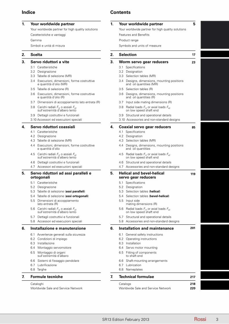
Indice Contents
1. Your worldwide partner 1. Your worldwide partner 5Your worldwide partner for high quality solutions Your worldwide partner for high quality solutions
Caratteristiche e vantaggi Features and Benefits
Gamma Product range
Simboli e unità di misura Symbols and units of measure
2. Scelta 2. Selection 17
3. Servo riduttori a vite 3. Worm servo gear reducers 23
3.1 Caratteristiche 3.1 Specifications3.2 Designazione 3.2 Designation3.3 Tabelle di selezione (MR) 3.3 Selection tables (MR)
3.4 Esecuzioni, dimensioni, forme costruttive e quantità d'olio (MR)
3.4 Designs, dimensions, mounting positions and oil quantities (MR)
3.5 Tabelle di selezione (R) 3.5 Selection tables (R)
3.6 Esecuzioni, dimensioni, forme costruttive e quantità d'olio (R)
3.6 Designs, dimensions, mounting positions and oil quantities (R)
3.7 Dimensioni di accoppiamento lato entrata (R) 3.7 Input side mating dimensions (R)
3.8 Carichi radiali Fr2 o assiali Fa2 sull'estremità d'albero lento
3.8 Radial loads Fr2 or axial loads Fa2 on low speed shaft end
3.9 Dettagli costruttivi e funzionali 3.9 Structural and operational details3.10 Accessori ed esecuzioni speciali 3.10 Accessories and non-standard designs
4. Servo riduttori coassiali 4. Coaxial servo gear reducers 854.1 Caratteristiche 4.1 Specifications4.2 Designazione 4.2 Designation4.3 Tabelle di selezione (MR) 4.3 Selection tables (MR)
4.4 Esecuzioni, dimensioni, forme costruttive e quantità d'olio
4.4 Designs, dimensions, mounting positions and oil quantities
4.5 Carichi radiali Fr2 o assiali Fa2 sull'estremità d'albero lento
4.5 Radial loads Fr2 or axial loads Fa2 on low speed shaft end
4.6 Dettagli costruttivi e funzionali 4.6 Structural and operational details4.7 Accessori ed esecuzioni speciali 4.7 Accessories and non-standard designs
5. Servo riduttori ad assi paralleli e ortogonali
5. Helical and bevel-helical servo gear reducers
119
5.1 Caratteristiche 5.1 Specifications5.2 Designazione 5.2 Designation5.3 Tabelle di selezione (assi paralleli) 5.3 Selection tables (helical)5.4 Tabelle di selezione (assi ortogonali) 5.4 Selection tables (bevel-helical)5.5 Dimensioni di accoppiamento
lato entrata (R)5.5 Input side
mating dimensions (R)
5.6 Carichi radiali Fr2 o assiali Fa2 sull'estremità d'albero lento
5.6 Radial loads Fr2 or axial loads Fa2 on low speed shaft end
5.7 Dettagli costruttivi e funzionali 5.7 Structural and operational details5.8 Accessori ed esecuzioni speciali 5.8 Accessories and non-standard designs
6. Installazione e manutenzione 6. Installation and maintenance 201
6.1 Avvertenze generali sulla sicurezza 6.1 General safety instructions6.2 Condizioni di impiego 6.2 Operating instructions6.3 Installazione 6.3 Installation6.4 Montaggio servomotore 6.4 Servo motor mounting
6.5 Montaggio di organi sull'estremità d'albero
6.5 Fitting of componentsto shaft end
6.6 Sistemi di fissaggio pendolare 6.6 Shaft-mounting arrangements6.7 Lubrificazione 6.7 Lubrication6.8 Targhe 6.8 Nameplates
7. Formule tecniche 7. Technical formulae 217
Cataloghi Catalogs 218Worldwide Sale and Service Network Worldwide Sale and Service Network 220

4 SR13 Edition February 2013
Pagina lasciata intenzionalmente biancaThis page is intentionally left blank

5SR13 Edition February 2013
Who we areIn brief:
1953 Year of foundation as family business and today still privately owned
Your worldwide partner for high quality solutions
70’s First in Italy to adopt a complete modular system for gear reducers with cylindrical and bevel gears; fi rst in Italy to adopt case-hardened, tempered, ground gear pairs on parallel and right angle shaft gear reducers
80’s Worm gear reducers and gearmotors with universal mounting, single-piece housing and ZI involute profi le; extension of the direct sales organization abroad with the facilities of the German, English, French and Spanish subsidiaries.
90’s Parallel and right angle shaft gear reducers and gearmotors with universal mounting and single-piece housing; fi rst transmission manufacturer in Italy and second in Europe to obtain Quality System Certifi cation ISO 9001.
1994 The only one to offer 3-year-warranty
1997 Acquisition of Seimec (Rossi Motor Division)
2002 Acquisition of SMEI (Rossi Planetary Gear Reducer Division, WIND)
2003 ISO 9001 – 2000 Standard (Vision 2000)
2004 New affi liated company in U.S.A.Habasit acquires important share in Rossi, to reinforce global presence and develop growth strategy
2009 (July) Habasit Holding owns 100% Rossi
2010 Logo and Company name change: from “Rossi Motoriduttori” to “Rossi S.p.A.”
For more than 50 years Rossi has been developing its business in the most demanding applications to become one of the world’s leading gearmotor manufacturers suitable for critical machines. Even in the toughest environment, Rossi is recognized for providing state of the art technology, solid value, and commitment to its customers.
Rossi in the 70’s
Rossi Industrial Gear Reducer Division, today
Rossi Motor Division
Rossi Planetary Gear Reducer Division
6 SR13 Edition February 2013
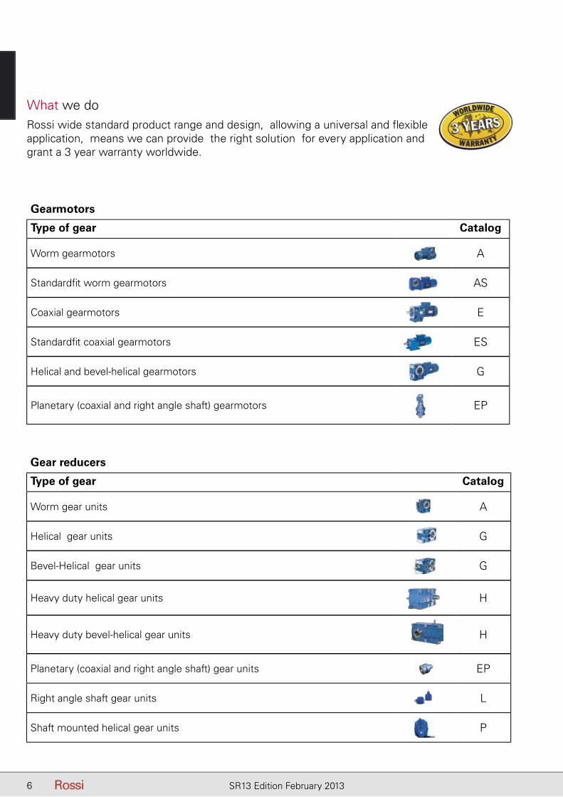
What we doRossi wide standard product range and design, allowing a universal and fl exible application, means we can provide the right solution for every application and grant a 3 year warranty worldwide.
Gearmotors
Type of gear Catalog
Worm gearmotors A
Standardfi t worm gearmotors AS
Coaxial gearmotors E
Standardfi t coaxial gearmotors ES
Helical and bevel-helical gearmotors G
Planetary (coaxial and right angle shaft) gearmotors EP
Gear reducers
Type of gear Catalog
Worm gear units A
Helical gear units G
Bevel-Helical gear units G
Heavy duty helical gear units H
Heavy duty bevel-helical gear units H
Planetary (coaxial and right angle shaft) gear units EP
Right angle shaft gear units L
Shaft mounted helical gear units P
7SR13 Edition February 2013
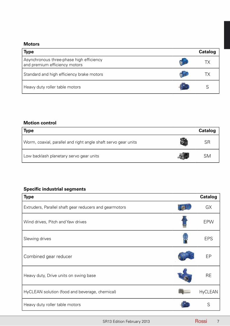
Motors
Type Catalog
Asynchronous three-phase high effi ciency and premium effi ciency motors TX
Standard and high effi ciency brake motors TX
Heavy duty roller table motors S
Motion control
Type Catalog
Worm, coaxial, parallel and right angle shaft servo gear units SR
Low backlash planetary servo gear units SM
Specifi c industrial segments
Type Catalog
Extruders, Parallel shaft gear reducers and gearmotors GX
Wind drives, Pitch and Yaw drives EPW
Slewing drives EPS
Combined gear reducer EP
Heavy duty, Drive units on swing base RE
HyCLEAN solution (food and beverage, chemical) HyCLEAN
Heavy duty roller table motors S

8 SR13 Edition February 2013
Where you can fi nd usClose to our customers in all fi ve continents, with a direct sale system granting excellence in service: visit our new website for your country reference. We are where you need us to be.
What we believe inChoosing the drive with the right technical specifi cations is vital for reliability and economy.We believe in integrity, ethical behavior, knowledge, imagination, innovation, good teamwork and above all customer focus: these are some of Rossi’s major key success factors.Rossi is a reliable company with the right fl exibility and know-how to respond to all market requests, all over the world, in all application fi elds, without leaving aside its commitment for the environment and value on human safety, to protect everyone’s future.
What we can do for youA highly skilled specialist team in different fi elds, Industry Segment Managers providing customers with the right support to fi nd the best solution suitable for your demands, and accompany you step by step alongside the whole supply.
Who you can callA well-organized after-sale service providing problem solving in the quickest possible way Rossi for You portal, allowing customers to have 24/7 access to all the documentations concerning Rossi supplies, news and order tracking in real time.Worldwide standard certifi ed to: IEC, UNEL, UNI, DIN, ATEX, UL, CSA, NEMA, MEPS, EISA, ErP (IE2, IE3)...
What you can do for usYou are at the center for Rossi: that’s why we want you to give us suggestions on our work, to inform us about news in your sector and anything that allows us to give you better service, from all points of view. You are for us a partner which can contribute to our ever evolving improvements in all fi elds.
9SR13 Edition February 2013
Pagina lasciata intenzionalmente biancaThis page is intentionally left blank
10 SR13 Edition February 2013
Caratteristiche e Vantaggi Features and Benefits
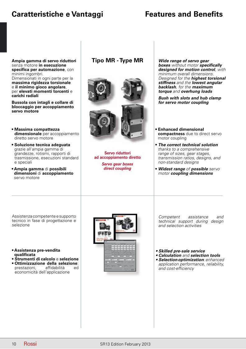
Ampia gamma di servo riduttori senza motore in esecuzione specifica per automazione, con minimi ingombri. Dimensionati in ogni parte per la massima rigidezza torsionale e il minimo gioco angolare, per elevati momenti torcenti e carichi radiali
Bussola con intagli e collare di bloccaggio per accoppiamento servo motore
• Massima compattezza dimensionale per accoppiamento diretto servo motore
• Soluzione tecnica adeguata grazie all'ampia gamma di grandezze, rotismi, rapporti di trasmissione, esecuzioni standard e speciali
• Ampia gamma di possibili dimensioni di accoppiamento servo motore
Wide range of servo gear boxes without motor specifically designed for motion control, with minimum overall dimensions. Designed for the highest torsional stiffness and the lowest angular backlash, for the maximum torque and overhung loads
Bush with slots and hub clamp for servo motor coupling
• Enhanced dimensional compactness due to direct servo motor coupling
• The correct technical solution thanks to a comprehensive range of sizes, gear stages, transmission ratios, designs, and non-standard designs
• Widest range of possible servo motor coupling dimensions
Servo riduttori ad accoppiamento diretto
Servo gear boxes direct coupling
Tipo MR - Type MR
Assistenza competente e supporto tecnico in fase di progettazione e selezione
• Assistenza pre-vendita qualificata
• Strumenti di calcolo e selezione• Ottimizzazione della selezione:
prestazioni, affidabilità ed economicità dell'applicazione
Competent assistance and technical support during design and selection activities
• Skilled pre-sale service• Calculation and selection tools• Selection optimization: enhanced
application performance, reliability, and cost-efficiency
11SR13 Edition February 2013
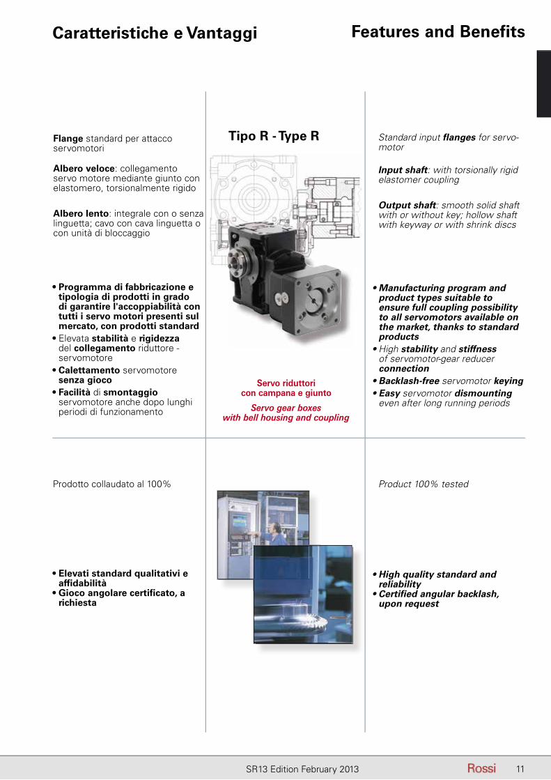
Flange standard per attacco servomotori
Albero veloce: collegamento servo motore mediante giunto con elastomero, torsionalmente rigido
Albero lento: integrale con o senza linguetta; cavo con cava linguetta o con unità di bloccaggio
• Programma di fabbricazione e tipologia di prodotti in grado di garantire l'accoppiabilità con tutti i servo motori presenti sul mercato, con prodotti standard
• Elevata stabilità e rigidezza del collegamento riduttore - servomotore
• Calettamento servomotore senza gioco
• Facilità di smontaggio servomotore anche dopo lunghi periodi di funzionamento
Standard input flanges for servo-motor
Input shaft: with torsionally rigid elastomer coupling
Output shaft: smooth solid shaft with or without key; hollow shaft with keyway or with shrink discs
• Manufacturing program and product types suitable to ensure full coupling possibility to all servomotors available on the market, thanks to standard products
• High stability and stiffness of servomotor-gear reducer connection
• Backlash-free servomotor keying• Easy servomotor dismounting
even after long running periods
Servo riduttori con campana e giunto
Servo gear boxes with bell housing and coupling
Tipo R - Type R
Caratteristiche e Vantaggi Features and Benefits
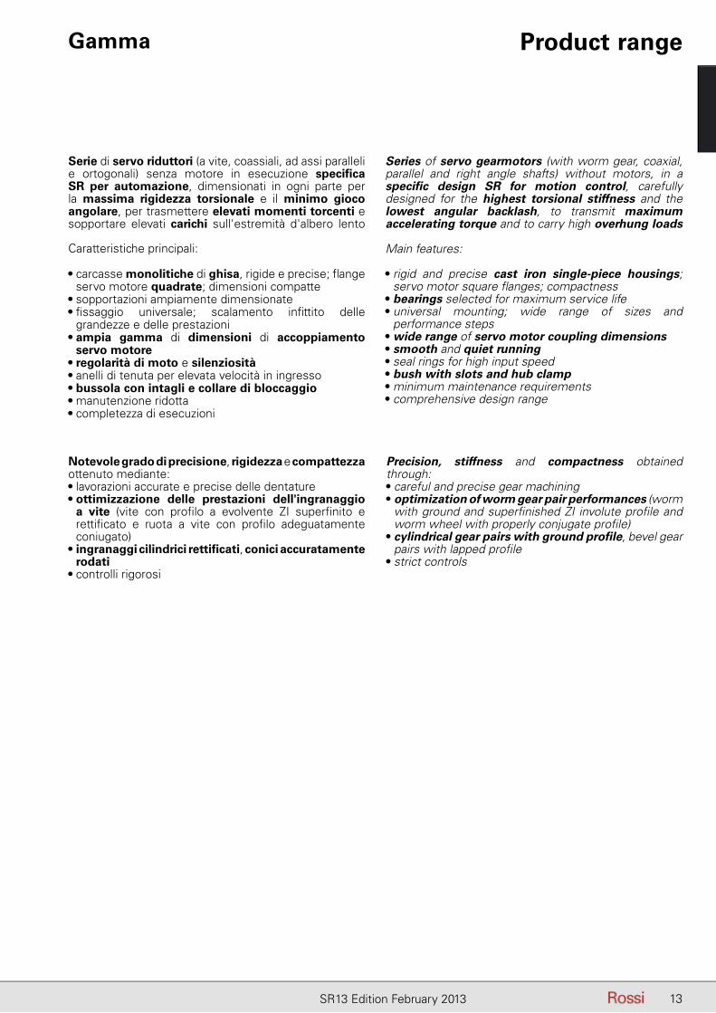
Prodotto collaudato al 100%
• Elevati standard qualitativi e affidabilità
• Gioco angolare certificato, a richiesta
Product 100% tested
• High quality standard and reliability
• Certified angular backlash, upon request

12 SR13 Edition February 2013
Pagina lasciata intenzionalmente biancaThis page is intentionally left blank
13SR13 Edition February 2013
Gamma Product range
Serie di servo riduttori (a vite, coassiali, ad assi paralleli e ortogonali) senza motore in esecuzione specifi ca SR per automazione, dimensionati in ogni parte per la massima rigidezza torsionale e il minimo gioco angolare, per trasmettere elevati momenti torcenti e sopportare elevati carichi sull'estremità d'albero lento
Caratteristiche principali:
• carcasse monolitiche di ghisa, rigide e precise; fl ange servo motore quadrate; dimensioni compatte
• sopportazioni ampiamente dimensionate• fi ssaggio universale; scalamento infi ttito delle
grandezze e delle prestazioni• ampia gamma di dimensioni di accoppiamento
servo motore• regolarità di moto e silenziosità• anelli di tenuta per elevata velocità in ingresso• bussola con intagli e collare di bloccaggio• manutenzione ridotta• completezza di esecuzioni
Series of servo gearmotors (with worm gear, coaxial, parallel and right angle shafts) without motors, in a specifi c design SR for motion control, carefully designed for the highest torsional stiffness and the lowest angular backlash, to transmit maximum accelerating torque and to carry high overhung loads
Main features:
• rigid and precise cast iron single-piece housings; servo motor square fl anges; compactness
• bearings selected for maximum service life• universal mounting; wide range of sizes and
performance steps• wide range of servo motor coupling dimensions• smooth and quiet running• seal rings for high input speed• bush with slots and hub clamp • minimum maintenance requirements• comprehensive design range
Notevole grado di precisione, rigidezza e compattezza ottenuto mediante:• lavorazioni accurate e precise delle dentature• ottimizzazione delle prestazioni dell'ingranaggio
a vite (vite con profi lo a evolvente ZI superfi nito e rettifi cato e ruota a vite con profi lo adeguatamente coniugato)
• ingranaggi cilindrici rettifi cati, conici accuratamente rodati
• controlli rigorosi
Precision, stiffness and compactness obtained through:• careful and precise gear machining• optimization of worm gear pair performances (worm
with ground and superfi nished ZI involute profi le and worm wheel with properly conjugate profi le)
• cylindrical gear pairs with ground profi le, bevel gear pairs with lapped profi le
• strict controls
14 SR13 Edition February 2013
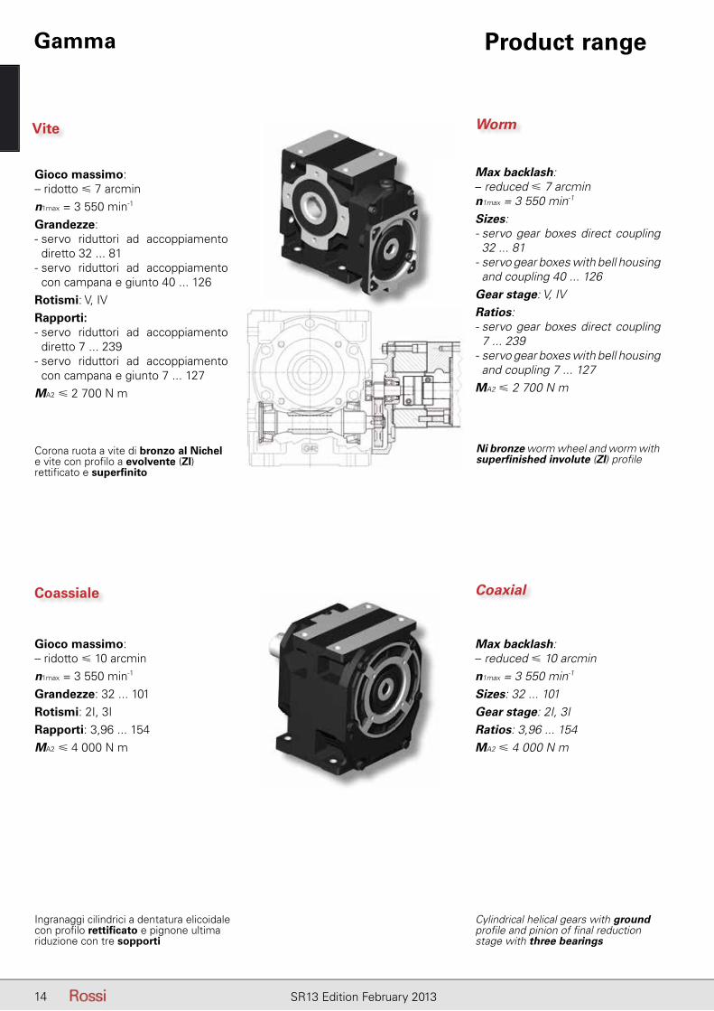
Vite
Gioco massimo:– ridotto � 7 arcminn1max = 3 550 min-1
Grandezze: - servo riduttori ad accoppiamento
diretto 32 ... 81- servo riduttori ad accoppiamento con campana e giunto 40 ... 126
Rotismi: V, IVRapporti: - servo riduttori ad accoppiamento diretto 7 ... 239
- servo riduttori ad accoppiamento con campana e giunto 7 ... 127
MA2 � 2 700 N m
Corona ruota a vite di bronzo al Nichel e vite con profi lo a evolvente (ZI) rettifi cato e superfi nito
Max backlash:– reduced � 7 arcminn1max = 3 550 min-1
Sizes: - servo gear boxes direct coupling 32 ... 81
- servo gear boxes with bell housing and coupling 40 ... 126
Gear stage: V, IVRatios: - servo gear boxes direct coupling 7 ... 239
- servo gear boxes with bell housing and coupling 7 ... 127
MA2 � 2 700 N m
Ni bronze worm wheel and worm with superfi nished involute (ZI) profi le
Coassiale
Gioco massimo:– ridotto � 10 arcminn1max = 3 550 min-1
Grandezze: 32 ... 101Rotismi: 2I, 3IRapporti: 3,96 ... 154MA2 � 4 000 N m
Ingranaggi cilindrici a dentatura elicoidale con profi lo rettifi cato e pignone ultima riduzione con tre sopporti
Max backlash:– reduced � 10 arcminn1max = 3 550 min-1
Sizes: 32 ... 101Gear stage: 2I, 3IRatios: 3,96 ... 154MA2 � 4 000 N m
Cylindrical helical gears with ground profi le and pinion of fi nal reduction stage with three bearings
Worm
Coaxial
Gamma Product range
15SR13 Edition February 2013
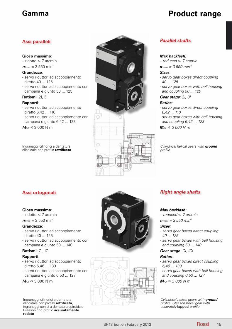
Assi paralleli
Gioco massimo:– ridotto � 7 arcminn1max = 3 550 min-1
Grandezze: - servo riduttori ad accoppiamento
diretto 40 ... 125- servo riduttori ad accoppiamento con
campana e giunto 50 ... 125Rotismi: 2I, 3IRapporti: - servo riduttori ad accoppiamento
diretto 6,42 ... 110- servo riduttori ad accoppiamento con
campana e giunto 6,42 ... 123MA2 � 3 000 N m
Ingranaggi cilindrici a dentatura elicoidale con profi lo rettifi cato
Max backlash:– reduced � 7 arcminn1max = 3 550 min-1
Sizes: - servo gear boxes direct coupling 40 ... 125
- servo gear boxes with bell housing and coupling 50 ... 125
Gear stage: 2I, 3IRatios: - servo gear boxes direct coupling 6,42 ... 110
- servo gear boxes with bell housing and coupling 6,42 ... 123
MA2 � 3 000 N m
Cylindrical helical gears with ground profi le
Assi ortogonali
Gioco massimo:– ridotto � 7 arcminn1max = 3 550 min-1
Grandezze: - servo riduttori ad accoppiamento
diretto 40 ... 125- servo riduttori ad accoppiamento con
campana e giunto 50 ... 140Rotismi: CI, ICIRapporti: - servo riduttori ad accoppiamento
diretto 6,46 ... 139- servo riduttori ad accoppiamento con
campana e giunto 6,53 ... 127MA2 � 3 000 N m
Ingranaggi cilindrici a dentatura elicoidale con profi lo rettifi cato, ingranaggi conici a dentatura spiroidale Gleason con profi lo accuratamente rodato
Max backlash:– reduced � 7 arcminn1max = 3 550 min-1
Sizes: - servo gear boxes direct coupling 40 ... 125
- servo gear boxes with bell housing and coupling 50 ... 140
Gear stage: CI, ICIRatios: - servo gear boxes direct coupling 6,46 ... 139
- servo gear boxes with bell housing and coupling 6,53 ... 127
MA2 � 3 000 N m
Cylindrical helical gears with ground profi le. Gleason bevel gear with accurately lapped profi le
Parallel shafts
Right angle shafts
Gamma Product range
16 SR13 Edition February 2013
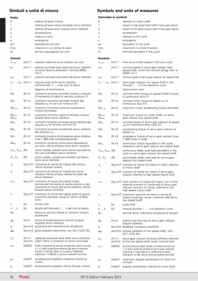
Subscripts to symbols
0 relevant to motor shaft1 relevant to high speed (input) shaft of servo gear reducer2 relevant to low speed (output) shaft of servo gear reducera accelerationc relevant to the cyclee emergencyeq equivalent in the cyclemax maximum in a field of valuesth thermal equivalent in the cycle
Symbolsn1 max [min-1] max servo motor speed in the duty cycle
nN1 [min-1] nominal speed of servo gear reducer high speed shaft, which the nominal ratings refer to (3000 min-1)
nN2 [min-1] nominal speed of servo gear reducer low speed shaft
n2 1 ... n2 n [min-1] servo gear reducer low speed shaft in the interval 1 ... n in the operation cycle
i transmission ratio
M01 [N m] nominal motor torque at speed 0 (stall torque) in continuous duty S1
MN1 [N m] nominal motor torque at speed nN0 (in continuous duty S1)
MA1max [N m] maximum motor accelerating torque admitted
M1max, M2max
[N m] maximum torque on motor shaft, on servo gear reducer low speed shaft
MN2 [N m] nominal torque of servo gear reducer at speed nN2 (in continuous duty cycle S1)
MA2 [N m] accelerating torque of servo gear reducer at speed nN2
ME2 [N m] emergency torque of servo gear reducer (max 1 000 times in total)
M2eq [N m] continuous torque equivalent in the cycle, referred to servo gear reducer low speed shaft
Fr2eq, Fa2eq [N] continuous radial, axial load equivalent in the cycle on servo gear reducer low speed shaft
Fr2, Fa2 [N] permissible radial, axial load on servo gear reducer low speed shaft
J0 [kg cm2] moment of inertia (of mass) of motor referred to motor shaft
J1 [kg cm2] moment of inertia (of mass) of servo gear reducer referred to high speed (input) shaft
J1tot [kg cm2] total moment of inertia (of mass), sum of the external moment of inertia and of servo gear reducer moment of inertia, referred to the high speed (input) shaft
J [kg cm2] maximum external moment of inertia (of mass) (couplings, driven machine) referred to low speed shaft
tc [s] cycle time
t1 ... tn [s] interval duration 1 … n of operation cycle
fsA service factor referred to accelerating torques
�s [mm] positioning error due to servo gear reducer angular backlash
p [arcmin] feedback transducer precision
�� [arcmin] angular backlash of low speed shaft, withM2 = 0,02 MN2
Ct2 [N m /arcmin]
servo gear reducer torsional stiffness referred to the low speed shaft under nominal load
LpA [dB(A)] sound pressure level (mean of measurement at 1 m from external profile of servo gear reducer standing in free field on a reflecting surface, tolerance +3 dB (A)) at nominal speed and load
�0 [rad/s2] maximum angular acceleration of motor (onno-load)
�1 [rad/s2] angular acceleration referred to motor shaft
Simboli e unità di misura Symbols and units of measures
Pedici0 relativo all’asse motore1 relativo all’asse veloce (entrata) servo riduttore2 relativo all’asse lento (uscita) servo riduttorea accelerazionec relativo al cicloe emergenzaeq equivalente nel ciclomax massimo in un campo di valorith termico equivalente nel ciclo
Simbolin1 max [min-1] velocità massima servo motore nel ciclo
nN1 [min-1] velocità nominale asse veloce del servo riduttore, cui sono riferite le prestazioni nominali (3000 min-1)
nN2 [min-1] velocità nominale asse lento del servo riduttore
n2 1 ... n2 n [min-1] velocità asse lento servo riduttore nell’intervallo 1 ... n del ciclo di lavoro
i rapporto di trasmissione
M01 [N m] momento torcente nominale motore a velocità 0 (momento di stallo) in servizio continuo S1
MN1 [N m] momento torcente nominale motore alla velocità nN0 (in servizio continuo S1)
MA1max [N m] massimo momento torcente accelerante motore ammesso
M1max, M2max
[N m] momento torcente massimo all’asse motore, all’asse lento servo riduttore
MN2 [N m] momento torcente nominale servo riduttore alla velocità nN2 (in servizio continuo S1)
MA2 [N m] momento torcente accelerante servo riduttore alla velocità nN2
ME2 [N m] momento torcente di emergenza servo riduttore (max 1 000 volte complessivamente)
M2eq [N m] momento torcente continuativo equivalente nel ciclo, riferito all’asse lento servo riduttore
Fr2eq, Fa2eq [N] carico radiale, assiale continuativo equivalente nel ciclo sull’albero servo riduttore
Fr2, Fa2 [N] carico radiale, assiale ammissibile sull’albero lento servo riduttore
J0 [kg cm2] momento di inerzia (di massa) del motore riferito all’asse motore
J1 [kg cm2] momento di inerzia (di massa) del servo riduttore riferito all’asse veloce (entrata) del servo riduttore
J1tot [kg cm2] momento di inerzia (di massa) totale, somma del momento di inerzia esterno e del momento di inerzia del servo riduttore, riferito all’asse veloce (entrata)
J [kg cm2] momento di inerzia (di massa) esterno (giunti, macchina azionata) massimo riferito all’asse lento
tc [s] tempo ciclo
t1 ... tn [s] durata dell’intervallo 1 ... n del ciclo di lavoro
fsA fattore di servizio riferito ai momenti torcenti acceleranti
�s [mm] errore di posizionamento dovuto al gioco angolare servo riduttore
p [arcmin] precisione del trasduttore di retroazione
�� [arcmin] gioco angolare asse lento, con M2 = 0,02 MN2
Ct2 [N m /arcmin]
rigidezza torsionale asse lento servo riduttore (valori riferiti a condizioni di carico nominale)
LpA [dB(A)] livello di pressione sonora (media dei valori misurati a 1 m dalla superficie esterna del servo riduttore situato in campo libero e su piano riflettente, tolleranza +3 dB(A)) a carico e velocità nominali
�0 [rad/s2] accelerazione angolare massima motore (a vuoto)
�1 [rad/s2] accelerazione angolare riferita all’asse motore
17SR13 Edition February 2013
SceltaSelection
Indice2 - Scelta ............................................................... 182a - Dati richiesti ...................................................... 182b - Selezione riduttore ............................................ 182c - Verifiche ............................................................ 19
Contents2 - Selection ........................................................... 182a - Required data .................................................... 182b - Gear reducer selection ..................................... 182c - Verifications ...................................................... 19
2
18 SR13 Edition February 2013
2 - Scelta 2 - Selection
2b - Selezione servo riduttore 2b - Servo gear reducer selectionIn base alla velocità e al momento torcente massimi richiesti dall’applicazione selezionare un servo riduttore per il quale:
MA2 � M2 max richiesto · fsA richiesto
i � n1max / n2 max richiesto
n1max � 3 550 min-1 (servizio S5 60%)
n1max � 3 000 min-1 (servizio S1)
MA2 [N m] è il momento torcente accelerante servo riduttore (ved. capp. 3, 4 e 5).
n1max è la velocità massima del servo motore nel ciclo.fsA fattore di servizio riferito al momento torcente accelerante.
According to the maximum output speed and torque required by the duty cycle select a servo gear reducer so that:
MA2 � M2 max required · fsA required
i � n1max / n2 max required
n1max � 3 550 min-1 (duty cycle S5 60%)
n1max � 3 000 min-1 (duty cycle S1)
MA2 [N m] is the accelerating torque of servo gear reducer (see ch. 3, 4 and 5).
n1max is the maximum servo motor speed within the duty cycle.fsA service factor referred to accelerating torque.
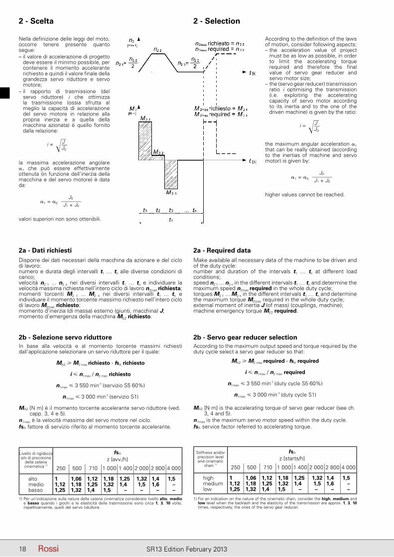
2a - Dati richiestiDisporre dei dati necessari della macchina da azionare e del ciclo di lavoro:numero e durata degli intervalli t1 … tn alle diverse condizioni di carico;velocità n2 1 ... n2 n nei diversi intervalli t1 … tn e individuare la velocità massima richiesta nell’intero ciclo di lavoro n2max richiesta;momenti torcenti M2 1 ... M2 n nei diversi intervalli t1 ... tn e individuare il momento torcente massimo richiesto nell’intero ciclo di lavoro M2max richiesto;momento d’inerzia (di massa) esterno (giunti, macchina) J;momento d’emergenza della macchina ME2 richiesto.
2a - Required dataMake available all necessary data of the machine to be driven and of the duty cycle:number and duration of the intervals t1 … tn at different load conditions;speed n2 1 ... n2 n in the different intervals t1 … tn and determine the maximum speed n2max required in the whole duty cycle;torques M2 1 ... M2 n in the different intervals t1 … tn and determine the maximum torque M2max required in the whole duty cycle;external moment of inertia J (of mass) (couplings, machine);machine emergency torque ME2 required.
Nella definizione delle leggi del moto, occorre tenere presente quanto segue:– il valore di accelerazione di progetto
deve essere il minimo possibile, per contenere il momento accelerante richiesto e quindi il valore finale della grandezza servo riduttore e servo motore;
– il rapporto di trasmissione (del servo riduttore) i che ottimizza la trasmissione (ossia sfrutta al meglio la capacità di accelerazione del servo motore in relazione alla propria inerzia e a quella della macchina azionata) è quello fornito dalla relazione:
i = �JJ0
la massima accelerazione angolare �1 che può essere effettivamente ottenuta (in funzione dell’inerzia della macchina e del servo motore) è data da:
J0
J1 + J0�1 = �0
valori superiori non sono ottenibili.
According to the definition of the laws of motion, consider following aspects:– the acceleration value of project
must be as low as possible, in order to limit the accelerating torque required and therefore the final value of servo gear reducer and servo motor size;
– the (servo gear reducer) transmission ratio i optimising the transmission (i.e. exploiting the accelerating capacity of servo motor according to its inertia and to the one of the driven machine) is given by the ratio:
i = �JJ0
the maximum angular acceleration �1 that can be really obtained (according to the inertias of machine and servo motor) is given by:
J0
J1 + J0�1 = �0
higher values cannot be reached.
Livello di rigidezza e/o di precisione
della catena cinematica 1)
fsA
z [avv./h]
250 500 710 1 000 1 400 2 000 2 800 4 000
alto 1 1,06 1,12 1,18 1,25 1,32 1,4 1,5medio 1,12 1,18 1,25 1,32 1,4 1,5 1,6 –basso 1,25 1,32 1,4 1,5 – – – –
1) Per un’indicazione sulla natura della catena cinematica considerare livello alto, medio e basso quando i giochi e le elasticità della trasmissione sono circa 1, 3, 10 volte, rispettivamente, quelli del servo riduttore.
1) For an indication on the nature of the cinematic chain, consider the high, medium and low level when the backlash and the elasticity of the transmission are approx. 1, 3, 10 times, respectively, the ones of the servo gear reducer.
Stiffness and/or precision level and cinematic
chain 1)
fsA
z [starts/h]
250 500 710 1 000 1 400 2 000 2 800 4 000
high 1 1,06 1,12 1,18 1,25 1,32 1,4 1,5medium 1,12 1,18 1,25 1,32 1,4 1,5 1,6 –low 1,25 1,32 1,4 1,5 – – – –
19SR13 Edition February 2013
2c - Verifiche 2c - Verifications
Dimensioni di accoppiamento servo motoreVerifi care che tra le diverse dimensioni di accoppiamento previste per il servo riduttore precedentemente selezionato (d×emax, S1, M1, N1) vi sia una confi gurazione compatibile con le dimensioni di accoppiamento del servo motore prescelto. In caso negativo, modifi care le selezioni o interpellarci.
Momento torcente equivalente M2eq
In base al servo riduttore precedentemente selezionato e ai dati della macchina da azionare, verifi care che:
M2eq � MN2
Se la condizione non è soddisfatta riesaminare, se possibile, i dati dell’applicazione o scegliere un servo riduttore di grandezza superiore.
M2eq [N m] è il momento torcente continuativo equivalente nel ciclo di lavoro, riferito all’asse lento servo riduttore:
M2eq = |M2 1|EXP · n2 1 · t1 + ... + |M2 n|EXP · n2 n · tn
nN2 · tc
EXP�EXP = 6,7 (6 per i riduttori a vite)
nN2 [min-1] è la velocità nominale (massima) asse lento servo riduttore (nN1 / i);
MN2 [N m] è il momento torcente nominale servo riduttore;
ti [s] durata intervallo 1 ... n nel ciclo di lavoro.
Momento torcente massimo M2max
In base al servo riduttore e al servo motore selezionati, verifi care che:
a) M2max · fsA richiesto � MA2
MA2 [N m] è il momento torcente accelerante servo riduttoreM2max [N m] è il momento torcente massimo all’asse lento servo
riduttore: M2max = M1max · i · η
M1max [N m] è il momento torcente massimo all’asse servo motore
i rapporto di trasmissioneη rendimento servo riduttore
b) M1max � MA1max
Se le condizioni a) e b) non sono soddisfatte, occorre limitare la corrente servo motore.
Momento torcente di emergenza ME2
In presenza di arresti di emergenza o di carichi sospesi, verifi care che:ME2 richiesto � ME2
Se la condizione non è soddisfatta, passare alla grandezza superiore.
ME2 richiesto [N m] è il momento torcente d’emergenza dell’applicazione.ME2 [N m] è il momento torcente d’emergenza (max 1 000 volte
complessivamente per non oltre 3 s ciascuna) che il servo riduttore può sopportare.
Servo motor coupling dimensionsVerify that the coupling dimensions of the servo motor selected matches with one of the possible coupling dimensions (d×emax, S1, M1, N1) available for the servo gear reducer selected before. If not, select another servo gear reducer or servo motor or consult us.
Equivalent torque M2eq
According to the driven machine data and to the servo gear reducer selected before, verify that:
M2eq � MN2
If the condition is not satisfi ed, re-examine, if possible, the application data or select a servo gear reducer of higher size.
M2eq [N m] is the continuous equivalent torque in the duty cycle, referred to the low speed shaft of servo gear reducer:
M2eq = |M2 1|EXP · n2 1 · t1 + ... + |M2 n|EXP · n2 n · tn
nN2 · tc
EXP�EXP = 6,7 (6 for worm gear reducer)
nN2 [min-1] is the nominal (maximum) speed of servo gear reducer low speed shaft (nN1 / i);
MN2 [N m] is the nominal servo gear reducer torque;
ti [s] duty cycle interval duration 1 ... n.
Maximum torque M2max
According to the servo gear reducer and to the servo motor selected, verify that:
a) M2max · fsA required � MA2
MA2 [N m] is the accelerating torque of servo gear reducerM2max [N m] is the maximum torque on servo gear reducer low
speed shaft: M2max = M1max · i · η
M1max [N m] is the maximum torque on servo motor shafti transmission ratioη servo gear reducer effi ciency
b) M1max � MA1max
If the conditions a) and b) are not satisfi ed, it is necessary to limit the servo motor current.
Emergency torque ME2
In presence of emergency stop and suspended loads, verify that:ME2 required � ME2
If the condition is not satisfi ed, use the next larger size.
ME2 required [N m] is the emergency torque of the applications.ME2 [N m] is the emergency torque (max 1 000 times in total
for not more than 3 s each) that can be supported by the servo gear reducer.
2 - Scelta 2 - Selection
20 SR13 Edition February 2013
2 - Scelta 2 - Selection
Carico radiale Fr2eq e assiale Fa2eq equivalenteVerifi care gli eventuali carichi radiali o assiali equivalenti (per carichi assiali disassati, interpellarci):
Fr2eq � Fr2
Fa2eq � Fa2
Fr2eq [N] è il carico radiale continuativo equivalente richiesto all’albero lento del servo riduttore (per coassiali grand. 81, 101, paralleli e ortogonali grand. 63 ... 125, utilizzare nella formula l'esponente 3 anziché 3,33).
Fr2eq =|Fr2 1|3,33 · n2 1 · t1 + ... + |Fr2 n|3,33 · n2 n · tn
nN2 · tc
3,33�Fr2 n [N] è il carico radiale riferito al singolo intervallo n del
ciclo di lavoro.
Fr2 n = k .2 · M2 n
d
M2 n [N m] è il momento torcente richiesto all'albero lento del servo riduttore, nel singolo intervallo n del ciclo di lavoro.
d [m] è il diametro primitivo dell'organo calettato sull'albero lento.
k è un coefficiente che assume valori diversi a seconda del tipo di trasmissione.
k = 1,5 per trasmissione a cinghia dentata;k = 1,1 per trasmissione a ingranaggio cilindrico a denti diritti;k = tg α / cosβ per trasmissioni a ingranaggio cilindrico elicoidale (α angolo
di pressione, β angolo d’elica.
nN2 [min-1] è la velocità nominale asse lento del servo riduttore:nN2 = nN1 / i.
Fr2 [N] è il carico radiale ammissibile indicato ai capp. 3.8, 4.5, 5.6.
ti [s] durata intervallo 1 ... n nel ciclo di lavoro.
Fa2eq [N] è il carico assiale continuativo equivalente richiesto all'albero lento del servo riduttore (per coassiali grand. 81, 101, paralleli e ortogonali grand. 63 ... 125, utilizzare nella formula l'esponente 3 anziché 3,33).
Fa2eq =|Fa2 1|3,33 · n2 1 · t1 + ... + |Fa2 n|3,33 · n2 n · tn
nN2 · tc
3,33�Fa2 n [N] è il carico assiale riferito al singolo intervallo n del
ciclo di lavoro; nel caso di trasmissione a ingranaggio cilindrico elicoidale vale:
Fa2 n = 2 · M2 n
d. tg β
β [rad] è l'angolo d'elica della dentatura elicoidale.
Fa2 [N] è il carico assiale ammissibile indicato ai capp. 3.8, 4.5, 5.6.
ti [s] durata intervallo 1 ... n nel ciclo di lavoro.
Equivalent radial Fr2eq and axial Fa2eq loadVerify the possible radial and axial loads (for misaligned axial loads, consult us):
Fr2eq � Fr2
Fa2eq � Fa2
Fr2eq [N] is the continuous equivalent radial load acting on servo gear reducer low speed shaft end (for coaxial sizes 81, 101, helical and bevel-helical sizes 63 ... 125, use in the formula the exponent 3 instead of 3,33).
Fr2eq =|Fr2 1|3,33 · n2 1 · t1 + ... + |Fr2 n|3,33 · n2 n · tn
nN2 · tc
3,33�Fr2 n [N] is the radial load referred to the single interval n of duty
cycle.
Fr2 n = k .2 · M2 n
d
M2 n [N m] is the torque required by servo gear reducer low speed shaft, in the single interval n of duty cycle.
d [m] is the pitch diameter of the drive fitted onto the low speed shaft.
k is a coefficient which assumes different values according to transmission type:
k = 1,5 for timing belt drive;k = 1,1 for spur gear drive;k = tg α / cosβ for helical gear drive (α pressure angle, β helix angle).
nN2 [min-1] is the servo gear reducer nominal output speed:nN2 = nN1 / i.
Fr2 [N] is the permissible radial load stated at ch. 3.8, 4.5, 5.6.
ti [s] duty cycle interval duration 1 ... n.
Fa2eq [N] is the continuous equivalent axial load acting on servo gear reducer low speed shaft end (for coaxial sizes 81, 101, helical and bevel-helical sizes 63 ... 125, use in the formula the exponent 3 instead of 3,33).
Fa2eq =|Fa2 1|3,33 · n2 1 · t1 + ... + |Fa2 n|3,33 · n2 n · tn
nN2 · tc
3,33�Fa2 n [N] is the axial load referred to the single interval n
of duty cycle; in case of helical gear drive, its value is given by:
Fa2 n = 2 · M2 n
d. tg β
β [rad] is the gear helix angle.
Fa2 [N] is the permissible radial load stated at ch. 3.8, 4.5, 5.6.
ti [s] duty cycle interval duration 1 ... n.
21SR13 Edition February 2013
Precisione di posizionamentoVerificare che l’errore di posizionamento dovuto ai giochi angolari del servo riduttore e alla risoluzione del trasduttore di retroazione utilizzato sul servo motore, sia inferiore al valore richiesto dall’applicazione:
�s = π · d
21 600 · �± �� ± pi � � �s richiesto
�s [mm] è l’errore di posizionamento;d [mm] è il diametro primitivo dell’organo calettato sull’albero
lento servo riduttore;
∆� [arcmin] è il valore del gioco angolare asse lento servo riduttore, (ved. capp. 3.9, 4.6, 5.7);
p [arcmin] è la precisione del trasduttore di retroazione; assumere 10 per resolver, 2,7 per encoder con 2 000 impulsi/giro, 5,4 per encoder con 1 000 impulsi/giro;
i è il rapporto di trasmissione del servo riduttore.
Positioning accuracyVerify that the positioning error due to angular backlash of servo gear reducer and to resolution of feedback transducer used on servo motor, is lower than the value requested by the application:
�s = π · d
21 600 · �± �� ± pi � � �s requested
�s [mm] is the positioning error;d [mm] is the pitch diameter of the unit keyed onto low speed
shaft of servo gear reducer;
∆� [arcmin] is the value of the servo gear reducer low speed shaft angular backlash (see ch. 3.9, 4.6, 5.7);
p [arcmin] is the precision of the feedback transducer; consider 10 for resolver, 2,7 for encoder with 2 000 ppr, 5,4 for encoder with 1 000 ppr;
i is the transmission ratio of the servo gear reducer.
2 - Scelta 2 - Selection

22 SR13 Edition February 2013
Pagina lasciata intenzionalmente biancaThis page is intentionally left blank

23SR13 Edition February 2013
Servo riduttori a viteWorm servo gear reducers
Indice3.1 - Caratteristiche .................................................. 243.2 - Designazione ................................................... 253.3 - Tabelle di selezione (MR) ................................. 263.4 - Esecuzioni, dimensioni, forme costruttive
e quantità d’olio (MR) ...................................... 38
3.5 - Tabelle di selezione (R) ..................................... 40
3.6 - Esecuzioni, dimensioni, forme costruttive e quantità d'olio (R) .......................................... 62
3.7 - Dimensioni di accoppiamento lato entrata (R) 64
3.8 - Carichi radiali Fr2 o assiali Fa2 sull’estremità d’albero lento .................................................. 66
3.9 - Dettagli costruttivi e funzionali ......................... 763.10 - Accessori ed esecuzioni speciali .................... 80
MR V 32 … 81MR IV 32 … 81
R V 40 … 126R IV 40 … 126
Contents3.1 - Specifications .................................................. 243.2 - Designation ..................................................... 253.3 - Selection tables (MR) ...................................... 263.4 - Designs, dimensions, mounting positions
and oil quantities (MR) ..................................... 38
3.5 - Selection tables (R) .......................................... 40
3.6 - Designs, dimensions, mounting positions and oil quantities (R) ........................................ 62
3.7 - Input side mating dimensions (R) .................... 64
3.8 - Radial loads Fr2 or axial loads Fa2 on low speed shaft end ................................... 66
3.9 - Structural and operational details .................... 763.10 - Accessories and non-standard designs ......... 80
3

24 SR13 Edition February 2013
3 - Servo riduttori a vite 3 - Worm servo gear reducers
3.1 Caratteristiche
– due diversi tipi di servo riduttore: tipo MR per accoppiamento diretto con il servo motore (massima compattezza) e tipo R per accoppiamento con campana e giunto torsionalmente rigido (massima fl essibilità di applicazione);
– 5 grandezze (di cui 2 doppie, per un totale di 7 grandezze: 32 … 81) servo riduttore tipo MR e 6 grandezze (di cui 3 doppie, per un totale di 9 grandezze: 40 … 126) per servo riduttore tipo R;
– ingranaggio a vite con o senza prerotismo (1 ingranaggio cilindrico);– rapporti di trasmissione «fi niti» (V);– 2 classi di gioco angolare asse lento: gioco normale o gioco ridotto
(a richiesta);– calettamento servo motore:
MR V, servo motore calettato direttamente nella vite mediante accoppiamento stretto con linguetta, intagli e collare di bloccaggio; disponibile anche accoppiamento senza linguetta in base al valore di MA1max;MR IV, servo motore con pignone prima riduzione calettato direttamente sull’estremità d’albero mediante interferenza e linguetta; R V e R IV, servo motore calettato mediante giunto torsionalmente rigido e campana di adattamento;
– possibilità di seconda sporgenza d’albero veloce (o intermedio per rotismo IV);
– vite con cuscinetti volventi a rulli conici contrapposti (obliquo a due corone di sfere più uno a sfere, per grand. 32); ruota a vite con cuscinetti volventi a sfere;
– albero lento cavo con cava linguetta e (grand. 63 ... 126) gole anello elastico per estrazione: di ghisa sferoidale (grigia per grand. 32 e 40) integrale con la ruota a vite; albero lento normale (sporgente a destra o a sinistra) o bisporgente (ved. cap. 3.10);
– fi ssaggio universale: con piedi integrali alla carcassa (inferiori, superiori e verticali sulla faccia opposta al motore) e con fl angia B14 (integrale alla carcassa per grand. 32 ... 50) sulle due facce di uscita dell’albero lento cavo; fl angia B5 con centraggio «foro» montabile sulle fl ange B14 (ved. cap. 3.10);
– anelli di tenuta per elevata velocità in entrata per tutte le grandezze;– lubrifi cazione a bagno d’olio (carcassa con elevata capienza) con
olio sintetico (cap. 6.7) per lubrifi cazione «lunga vita»: servo riduttori con un tappo (grand. 32 ... 64) o due tappi (grand. 80, 81) forniti completi di olio; con tappo di carico con valvola, scarico e livello (grandezze 100 … 126) forniti senza olio;
– verniciatura: protezione esterna con smalto bicomponente poliacrilico all’acqua, nero RAL 9005 (opacità 5 glass), idonea a resistere agli agenti atmosferici e aggressivi (classe di corrosività C3 secondo ISO 12944-2) e a consentire ulteriori fi niture con prodotti bicomponente; protezione interna con vernice a polveri epossidiche (grand. 32 … 81) o epossidica (grand. 100 … 126) idonee a resistere agli oli sintetici.
Rotismo:– a vite: a 1 ingranaggio cilindrico e vite;– ingranaggi a vite con rapporti di trasmissione (i = 7 ... 63) interi e
uguali per le diverse grandezze;– rapporti di trasmissione nominali secondo R10 (8 ... 315);– vite cilindrica di acciaio 16 CrNi4 UNI 7846-78 cementata/temprata
con profi lo a evolvente (ZI) rettifi cato e superfi nito;– ruota a vite con profi lo adeguatamente coniugato a quello della vite
tramite ottimizzazione del creatore, con mozzo di ghisa sferoidale o grigia (secondo la grandezza) e corona di bronzo fosforoso PB2 BS 1400-85;
– ingranaggio cilindrico di acciaio 16 CrNi4 UNI 7846-78 cementato/ temprato con profi lo rettifi cato, dentatura elicoidale;
– capacità di carico del rotismo calcolata a rottura e a usura; verifi ca capacità termica.
3.1 Specifications
– two different gear reducer types: type MR for direct coupling with the servo motor (maximum compactness) and type R for coupling with bell and torsionally stiff coupling (wide range of mating dimensions);
– 5 servo gear reducer sizes (with 2 size pairs, for a total of 7 sizes: 32 … 81) for type MR and 6 servo gear reducer sizes (with 3 size pairs, for a total of 9 sizes: 40 ... 126) for type R;
– worm gear pair with or without fi rst reduction stage (1 cylindrical gear pair);
– «fi nite» transmission ratio (V);– 2 classes of low speed shaft angular backlash: standard backlash
or reduced backlash (on request);– servo motor coupling:
MR V, servo motor directly fi tted into the worm with key, slots and hub clamp; coupling without key available based on MA1max;MR IV, servo motor with fi rst reduction stage pinion directly fi tted with interference and key onto the shaft end; R V and R IV, servo motor fi tted through torsionally stiff coupling and bell housing;
– possibility of second high speed shaft extension (or intermediate shaft extension for train of gears IV);
– bearings on worm: face-to-face taper roller bearings (double row angular contact ball bearings plus ball bearing, for size 32); ball bearings on worm-wheel;
– hollow low speed shaft with keyway and (sizes 63 ... 126) with circlip groove for removal purposes: in nodular cast iron (grey cast iron for size 32 and 40) integral with worm wheel; standard (left or right extension) or double extension low speed shaft (see ch. 3.10);
– universal mounting having feet integral with housing (lower, upper feet and vertical on the face opposite to motor) and B14 fl ange (integral with housing for sizes 32 ... 50) on two faces of hollow speed shaft output; B5 fl ange with spigot «recess» which can be mounted onto B14 fl anges (see ch. 3.10);
– seal rings for high input speed, available for all sizes;– oil bath lubrication (high oil capacity housing) with synthetic oil (ch.
6.7) for «long-life»: units provided with one plug (sizes 32 ... 64) or two plugs (sizes 80, 81) supplied fi lled with oil; with fi ller plug with valve, drain plug and level plug (sizes 100 … 126) supplied without oil;
– paint: external coating with water-soluble polyacriyiic dual-compound enamel, colour black RAL 9005 (opacity 5 glass), suitable to resist the atmospheric and aggressive agents (atmospheric corrosivity category C3 according to ISO 12944-2) and to allow further fi nishing with dual-compound paints; internal protection in epoxy powder paint (sizes 32 ... 81) or epoxy paint (sizes 100 ... 126) appropriate for resistance to synthetic oils.
Train of gears:– worm gear pair; 1 cylindrical gear pair plus worm;– worm gear pairs, with whole-number transmission ratios (i = 7 ...
63) identical for the different sizes;– nominal transmission ratios to R10 series (8 ... 315);– casehardened and hardened cylindrical worm in 16 CrNi4 UNI7846-
78 steel with ground and superfi nished involute profi le (ZI);– wormwheel with profi le especially conjugate to worm through hob
optimization, with hub in nodular or grey cast iron (depending on size) and PB2 BS 1400-85 phosphor bronze gear rim;
– casehardened and hardened cylindrical gear pairs in 16 CrNi4 UNI 7846-78 steel with ground profi le and helical toothing;
– gears load capacity calculated for breakage and wear; thermal capacity verifi ed.
24 SR13 Edition February 2013
25SR13 Edition February 2013
3 - Servo riduttori a vite 3 - Worm servo gear reducers
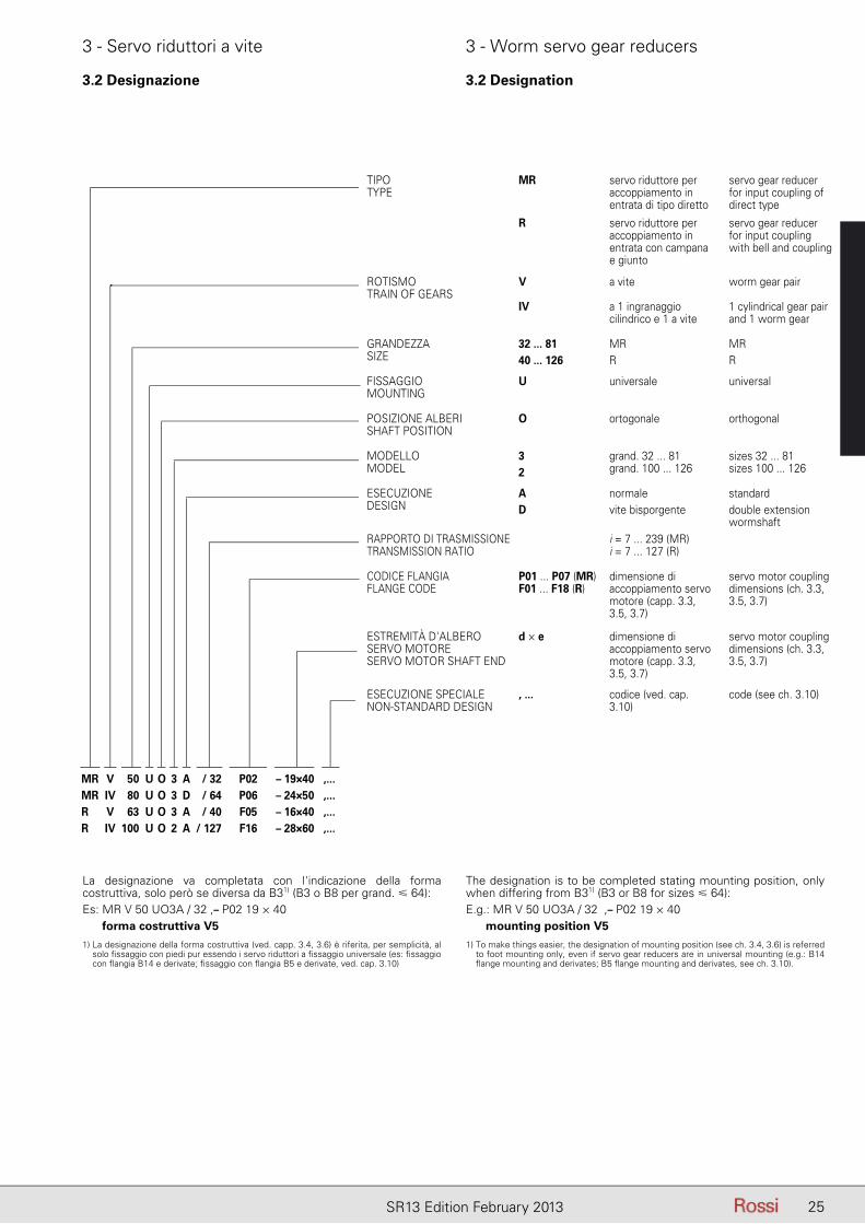
TIPOTYPE
MR servo riduttore per accoppiamento in entrata di tipo diretto
servo gear reducer for input coupling of direct type
R servo riduttore per accoppiamento in entrata con campana e giunto
servo gear reducer for input coupling with bell and coupling
ROTISMOTRAIN OF GEARS
V a vite worm gear pair
IV a 1 ingranaggio cilindrico e 1 a vite
1 cylindrical gear pair and 1 worm gear
GRANDEZZASIZE
32 ... 8140 ... 126
MRR
MRR
FISSAGGIOMOUNTING
U universale universal
POSIZIONE ALBERISHAFT POSITION
O ortogonale orthogonal
MODELLOMODEL
32
grand. 32 ... 81grand. 100 ... 126
sizes 32 ... 81sizes 100 ... 126
ESECUZIONEDESIGN
AD
normalevite bisporgente
standarddouble extension wormshaft
RAPPORTO DI TRASMISSIONETRANSMISSION RATIO
i = 7 ... 239 (MR)i = 7 ... 127 (R)
CODICE FLANGIAFLANGE CODE
P01 ... P07 (MR)F01 ... F18 (R)
dimensione di accoppiamento servo motore (capp. 3.3, 3.5, 3.7)
servo motor coupling dimensions (ch. 3.3, 3.5, 3.7)
ESTREMITÀ D'ALBERO SERVO MOTORESERVO MOTOR SHAFT END
d × e dimensione di accoppiamento servo motore (capp. 3.3, 3.5, 3.7)
servo motor coupling dimensions (ch. 3.3, 3.5, 3.7)
ESECUZIONE SPECIALE NON-STANDARD DESIGN
, ... codice (ved. cap. 3.10)
code (see ch. 3.10)
MR V 50 U O 3 A / 32 P02 – 19×40 ,...MR IV 80 U O 3 D / 64 P06 – 24×50 ,...R V 63 U O 3 A / 40 F05 – 16×40 ,...R IV 100 U O 2 A / 127 F16 – 28×60 ,...
La designazione va completata con l'indicazione della forma costruttiva, solo però se diversa da B31) (B3 o B8 per grand. � 64):Es: MR V 50 UO3A / 32 ,– P02 19 × 40
forma costruttiva V5
1) La designazione della forma costruttiva (ved. capp. 3.4, 3.6) è riferita, per semplicità, al solo fi ssaggio con piedi pur essendo i servo riduttori a fi ssaggio universale (es: fi ssaggio con fl angia B14 e derivate; fi ssaggio con fl angia B5 e derivate, ved. cap. 3.10)
The designation is to be completed stating mounting position, only when differing from B31) (B3 or B8 for sizes � 64):E.g.: MR V 50 UO3A / 32 ,– P02 19 × 40
mounting position V5
1) To make things easier, the designation of mounting position (see ch. 3.4, 3.6) is referred to foot mounting only, even if servo gear reducers are in universal mounting (e.g.: B14 fl ange mounting and derivates; B5 fl ange mounting and derivates, see ch. 3.10).
3.2 Designazione 3.2 Designation
26 SR13 Edition February 2013
3 - Servo riduttori a vite 3 - Worm servo gear reducers
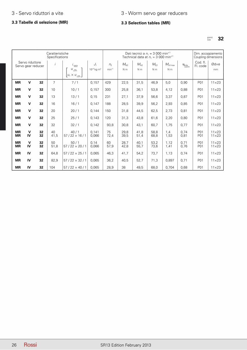
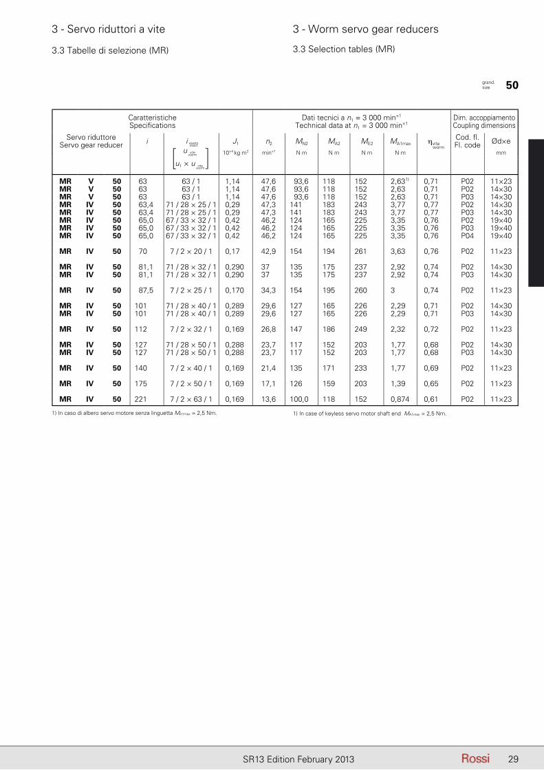
3.3 Tabelle di selezione (MR) 3.3 Selection tables (MR)
CaratteristicheSpecifications
Dati tecnici a n1 = 3 000 min×1
Technical data at n1 = 3 000 min×1Dim. accoppiamento Coupling dimensions
Servo riduttoreServo gear reducer i J1 n2 MN2 MA2 ME2 MA1max ηvite
Cod. fl.Fl. code Ød×e
10×4 kg m2 min×1 N m N m N m N m mm
MR V 32 7 7 / 1 0,157 429 22,5 31,5 46,9 5,0 0,90 P01 11×23
MR V 32 10 10 / 1 0,157 300 25,8 36,1 53,8 4,12 0,88 P01 11×23
MR V 32 13 13 / 1 0,15 231 27,1 37,9 56,6 3,37 0,87 P01 11×23
MR V 32 16 16 / 1 0,147 188 28,5 39,9 56,2 2,93 0,85 P01 11×23
MR V 32 20 20 / 1 0,144 150 31,8 44,5 62,5 2,73 0,81 P01 11×23
MR V 32 25 25 / 1 0,143 120 31,3 43,8 61,6 2,20 0,80 P01 11×23
MR V 32 32 32 / 1 0,142 93,8 30,8 43,1 60,7 1,75 0,77 P01 11×23
MR V 32 40 40 / 1 0,141 75 29,8 41,8 58,8 1,4 0,74 P01 11×23MR IV 32 41,5 57 / 22 × 16 / 1 0,066 72,4 39,5 51,4 68,8 1,53 0,81 P01 11×23
MR V 32 50 50 / 1 0,14 60 28,7 40,1 53,2 1,12 0,71 P01 11×23MR IV 32 51,8 57 / 22 × 20 / 1 0,066 57,9 42,8 55,7 73,6 1,41 0,76 P01 11×23
MR IV 32 64,8 57 / 22 × 25 / 1 0,065 46,3 41,7 54,2 73,7 1,13 0,74 P01 11×23
MR IV 32 82,9 57 / 22 × 32 / 1 0,065 36,2 40,5 52,7 71,3 0,897 0,71 P01 11×23
MR IV 32 104 57 / 22 × 40 / 1 0,065 28,9 38 49,5 68,0 0,704 0,68 P01 11×23
grand. size 32
i esatto
u
u1 × u
viteworm
viteworm
[ ]i esatto
exact worm
27SR13 Edition February 2013
3 - Servo riduttori a vite 3 - Worm servo gear reducers
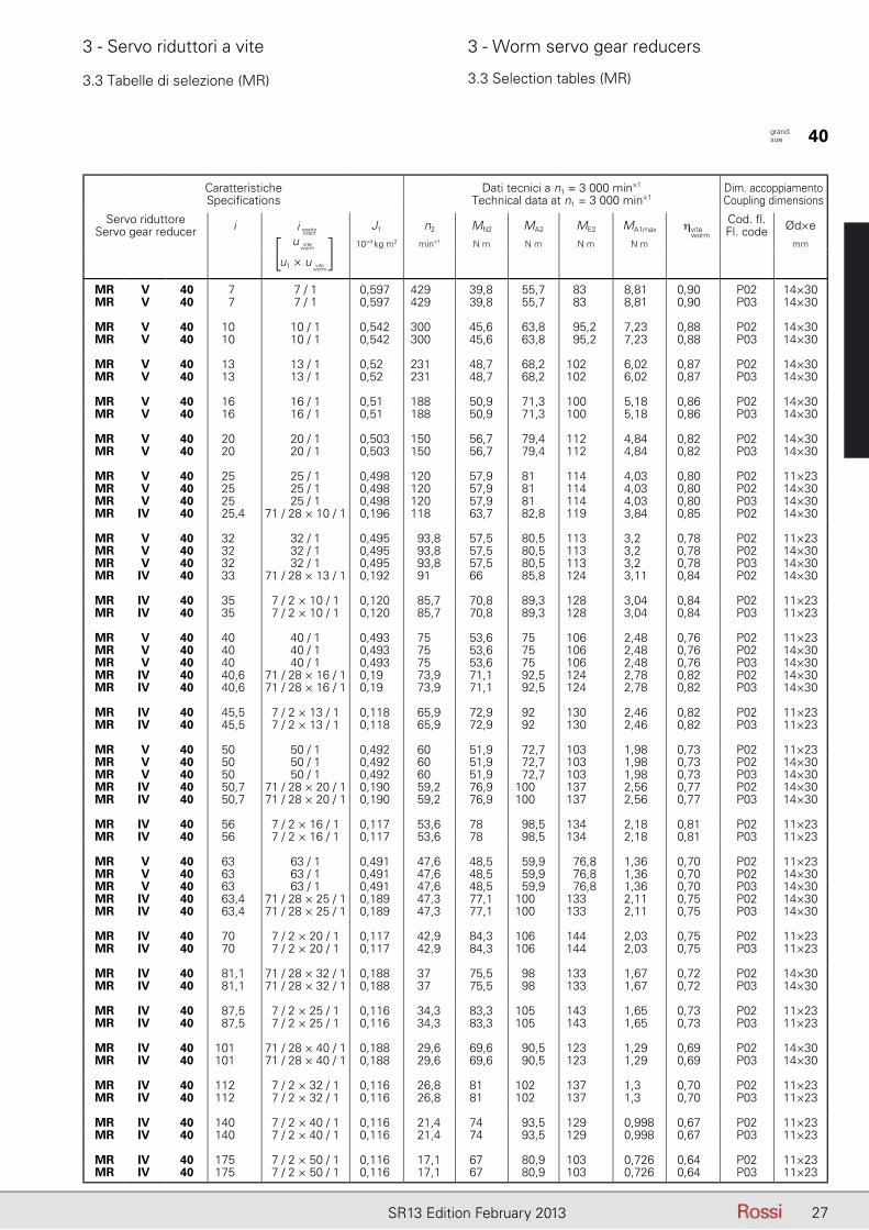
3.3 Tabelle di selezione (MR) 3.3 Selection tables (MR)
CaratteristicheSpecifications
Dati tecnici a n1 = 3 000 min×1
Technical data at n1 = 3 000 min×1Dim. accoppiamento Coupling dimensions
Servo riduttoreServo gear reducer i J1 n2 MN2 MA2 ME2 MA1max ηvite
Cod. fl.Fl. code Ød×e
10×4 kg m2 min×1 N m N m N m N m mm
MR V 40 7,0 7 / 1 0,597 429 39,8 55,7 83,0 8,81 0,90 P02 14×30MR V 40 7,0 7 / 1 0,597 429 39,8 55,7 83,0 8,81 0,90 P03 14×30
MR V 40 10 10 / 1 0,542 300 45,6 63,8 95,2 7,23 0,88 P02 14×30MR V 40 10 10 / 1 0,542 300 45,6 63,8 95,2 7,23 0,88 P03 14×30
MR V 40 13 13 / 1 0,52 231 48,7 68,2 102 6,02 0,87 P02 14×30MR V 40 13 13 / 1 0,52 231 48,7 68,2 102 6,02 0,87 P03 14×30
MR V 40 16 16 / 1 0,51 188 50,9 71,3 100 5,18 0,86 P02 14×30MR V 40 16 16 / 1 0,51 188 50,9 71,3 100 5,18 0,86 P03 14×30
MR V 40 20 20 / 1 0,503 150 56,7 79,4 112 4,84 0,82 P02 14×30MR V 40 20 20 / 1 0,503 150 56,7 79,4 112 4,84 0,82 P03 14×30
MR V 40 25 25 / 1 0,498 120 57,9 81 114 4,03 0,80 P02 11×23MR V 40 25 25 / 1 0,498 120 57,9 81 114 4,03 0,80 P02 14×30MR V 40 25 25 / 1 0,498 120 57,9 81 114 4,03 0,80 P03 14×30MR IV 40 25,4 71 / 28 × 10 / 1 0,196 118 63,7 82,8 119 3,84 0,85 P02 14×30
MR V 40 32 32 / 1 0,495 93,8 57,5 80,5 113 3,2 0,78 P02 11×23MR V 40 32 32 / 1 0,495 93,8 57,5 80,5 113 3,2 0,78 P02 14×30MR V 40 32 32 / 1 0,495 93,8 57,5 80,5 113 3,2 0,78 P03 14×30MR IV 40 33,0 71 / 28 × 13 / 1 0,192 91 66 85,8 124 3,11 0,84 P02 14×30
MR IV 40 35 7 / 2 × 10 / 1 0,120 85,7 70,8 89,3 128 3,04 0,84 P02 11×23MR IV 40 35 7 / 2 × 10 / 1 0,120 85,7 70,8 89,3 128 3,04 0,84 P03 11×23
MR V 40 40 40 / 1 0,493 75 53,6 75 106 2,48 0,76 P02 11×23MR V 40 40 40 / 1 0,493 75 53,6 75 106 2,48 0,76 P02 14×30MR V 40 40 40 / 1 0,493 75 53,6 75 106 2,48 0,76 P03 14×30MR IV 40 40,6 71 / 28 × 16 / 1 0,19 73,9 71,1 92,5 124 2,78 0,82 P02 14×30MR IV 40 40,6 71 / 28 × 16 / 1 0,19 73,9 71,1 92,5 124 2,78 0,82 P03 14×30
MR IV 40 45,5 7 / 2 × 13 / 1 0,118 65,9 72,9 92 130 2,46 0,82 P02 11×23MR IV 40 45,5 7 / 2 × 13 / 1 0,118 65,9 72,9 92 130 2,46 0,82 P03 11×23
MR V 40 50 50 / 1 0,492 60 51,9 72,7 103 1,98 0,73 P02 11×23MR V 40 50 50 / 1 0,492 60 51,9 72,7 103 1,98 0,73 P02 14×30MR V 40 50 50 / 1 0,492 60 51,9 72,7 103 1,98 0,73 P03 14×30MR IV 40 50,7 71 / 28 × 20 / 1 0,190 59,2 76,9 100,0 137 2,56 0,77 P02 14×30MR IV 40 50,7 71 / 28 × 20 / 1 0,190 59,2 76,9 100,0 137 2,56 0,77 P03 14×30
MR IV 40 56 7 / 2 × 16 / 1 0,117 53,6 78 98,5 134 2,18 0,81 P02 11×23MR IV 40 56 7 / 2 × 16 / 1 0,117 53,6 78 98,5 134 2,18 0,81 P03 11×23
MR V 40 63 63 / 1 0,491 47,6 48,5 59,9 76,8 1,36 0,70 P02 11×23MR V 40 63 63 / 1 0,491 47,6 48,5 59,9 76,8 1,36 0,70 P02 14×30MR V 40 63 63 / 1 0,491 47,6 48,5 59,9 76,8 1,36 0,70 P03 14×30MR IV 40 63,4 71 / 28 × 25 / 1 0,189 47,3 77,1 100 133 2,11 0,75 P02 14×30MR IV 40 63,4 71 / 28 × 25 / 1 0,189 47,3 77,1 100 133 2,11 0,75 P03 14×30
MR IV 40 70 7 / 2 × 20 / 1 0,117 42,9 84,3 106 144 2,03 0,75 P02 11×23MR IV 40 70 7 / 2 × 20 / 1 0,117 42,9 84,3 106 144 2,03 0,75 P03 11×23
MR IV 40 81,1 71 / 28 × 32 / 1 0,188 37,0 75,5 98 133 1,67 0,72 P02 14×30MR IV 40 81,1 71 / 28 × 32 / 1 0,188 37,0 75,5 98 133 1,67 0,72 P03 14×30
MR IV 40 87,5 7 / 2 × 25 / 1 0,116 34,3 83,3 105 143 1,65 0,73 P02 11×23MR IV 40 87,5 7 / 2 × 25 / 1 0,116 34,3 83,3 105 143 1,65 0,73 P03 11×23
MR IV 40 101 71 / 28 × 40 / 1 0,188 29,6 69,6 90,5 123 1,29 0,69 P02 14×30MR IV 40 101 71 / 28 × 40 / 1 0,188 29,6 69,6 90,5 123 1,29 0,69 P03 14×30
MR IV 40 112 7 / 2 × 32 / 1 0,116 26,8 81 102 137 1,3 0,70 P02 11×23MR IV 40 112 7 / 2 × 32 / 1 0,116 26,8 81 102 137 1,3 0,70 P03 11×23
MR IV 40 140 7 / 2 × 40 / 1 0,116 21,4 74 93,5 129 0,998 0,67 P02 11×23MR IV 40 140 7 / 2 × 40 / 1 0,116 21,4 74 93,5 129 0,998 0,67 P03 11×23
MR IV 40 175 7 / 2 × 50 / 1 0,116 17,1 67 80,9 103 0,726 0,64 P02 11×23MR IV 40 175 7 / 2 × 50 / 1 0,116 17,1 67 80,9 103 0,726 0,64 P03 11×23
grand. size 40
i esatto
u
u1 × u
viteworm
viteworm
[ ]i esatto
exact worm
28 SR13 Edition February 2013
3 - Servo riduttori a vite 3 - Worm servo gear reducers
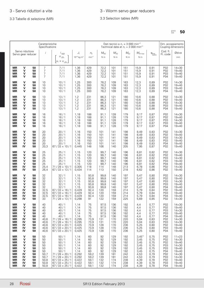
3.3 Tabelle di selezione (MR) 3.3 Selection tables (MR)
CaratteristicheSpecifications
Dati tecnici a n1 = 3 000 min×1
Technical data at n1 = 3 000 min×1Dim. accoppiamento Coupling dimensions
Servo riduttoreServo gear reducer i J1 n2 MN2 MA2 ME2 MA1max ηvite
Cod. fl.Fl. code Ød×e
10×4 kg m2 min×1 N m N m N m N m mm
MR V 50 7,0 7 / 1 1,36 429 72,2 101 151 15,9 0,91 P02 14×30MR V 50 7,0 7 / 1 1,36 429 72,2 101 151 15,9 0,91 P02 19×40MR V 50 7,0 7 / 1 1,36 429 72,2 101 151 15,9 0,91 P03 19×40MR V 50 7,0 7 / 1 1,36 429 72,2 101 151 15,9 0,91 P04 19×40
MR V 50 10 10 / 1 1,25 300 78,2 109 163 12,3 0,89 P02 14×30MR V 50 10 10 / 1 1,25 300 78,2 109 163 12,3 0,89 P02 19×40MR V 50 10 10 / 1 1,25 300 78,2 109 163 12,3 0,89 P03 19×40MR V 50 10 10 / 1 1,25 300 78,2 109 163 12,3 0,89 P04 19×40
MR V 50 13 13 / 1 1,2 231 86,3 121 180 10,6 0,88 P02 14×30MR V 50 13 13 / 1 1,2 231 86,3 121 180 10,6 0,88 P02 19×40MR V 50 13 13 / 1 1,2 231 86,3 121 180 10,6 0,88 P03 14×30MR V 50 13 13 / 1 1,2 231 86,3 121 180 10,6 0,88 P03 19×40MR V 50 13 13 / 1 1,2 231 86,3 121 180 10,6 0,88 P04 19×40
MR V 50 16 16 / 1 1,18 188 91,1 128 179 9,17 0,87 P02 14×30MR V 50 16 16 / 1 1,18 188 91,1 128 179 9,17 0,87 P02 19×40MR V 50 16 16 / 1 1,18 188 91,1 128 179 9,17 0,87 P03 14×30MR V 50 16 16 / 1 1,18 188 91,1 128 179 9,17 0,87 P03 19×40MR V 50 16 16 / 1 1,18 188 91,1 128 179 9,17 0,87 P04 19×40
MR V 50 20 20 / 1 1,16 150 101 141 198 8,49 0,83 P02 14×30MR V 50 20 20 / 1 1,16 150 101 141 198 8,49 0,83 P02 19×40MR V 50 20 20 / 1 1,16 150 101 141 198 8,49 0,83 P03 14×30MR V 50 20 20 / 1 1,16 150 101 141 198 8,49 0,83 P03 19×40MR V 50 20 20 / 1 1,16 150 101 141 198 8,49 0,83 P04 19×40MR IV 50 20,3 67 / 33 × 10 / 1 0,445 148 106 140 205 7,95 0,87 P02 19×40
MR V 50 25 25 / 1 1,15 120 99,7 140 196 6,81 0,82 P02 14×30MR V 50 25 25 / 1 1,15 120 99,7 140 196 6,81 0,82 P02 19×40MR V 50 25 25 / 1 1,15 120 99,7 140 196 6,81 0,82 P03 14×30MR V 50 25 25 / 1 1,15 120 99,7 140 196 6,81 0,82 P03 19×40MR V 50 25 25 / 1 1,15 120 99,7 140 196 6,81 0,82 P04 19×40MR IV 50 25,4 71 / 28 × 10 / 1 0,305 118 114 148 213 6,78 0,86 P02 14×30MR IV 50 26,4 67 / 33 × 13 / 1 0,434 114 113 150 218 6,62 0,86 P02 19×40
MR V 50 32 32 / 1 1,15 93,8 99,8 140 197 5,47 0,80 P02 14×30MR V 50 32 32 / 1 1,15 93,8 99,8 140 197 5,47 0,80 P02 19×40MR V 50 32 32 / 1 1,15 93,8 99,8 140 197 5,47 0,80 P03 14×30MR V 50 32 32 / 1 1,15 93,8 99,8 140 197 5,47 0,80 P03 19×40MR V 50 32 32 / 1 1,15 93,8 99,8 140 197 5,47 0,80 P04 19×40MR IV 50 32,5 67 / 33 × 16 / 1 0,429 92,4 120 159 214 5,79 0,84 P02 19×40MR IV 50 32,5 67 / 33 × 16 / 1 0,429 92,4 120 159 214 5,79 0,84 P03 19×40MR IV 50 32,5 67 / 33 × 16 / 1 0,429 92,4 120 159 214 5,79 0,84 P04 19×40MR IV 50 33,0 71 / 28 × 13 / 1 0,298 91 122 159 225 5,69 0,85 P02 14×30
MR V 50 40 40 / 1 1,14 75 97,5 136 192 4,4 0,77 P02 14×30MR V 50 40 40 / 1 1,14 75 97,5 136 192 4,4 0,77 P02 19×40MR V 50 40 40 / 1 1,14 75 97,5 136 192 4,4 0,77 P03 14×30MR V 50 40 40 / 1 1,14 75 97,5 136 192 4,4 0,77 P03 19×40MR V 50 40 40 / 1 1,14 75 97,5 136 192 4,4 0,77 P04 19×40MR IV 50 40,6 71 / 28 × 16 / 1 0,295 73,9 131 170 220 5,04 0,83 P02 14×30MR IV 50 40,6 71 / 28 × 16 / 1 0,295 73,9 131 170 220 5,04 0,83 P03 14×30MR IV 50 40,6 67 / 33 × 20 / 1 0,425 73,9 128 170 236 5,25 0,80 P02 19×40MR IV 50 40,6 67 / 33 × 20 / 1 0,425 73,9 128 170 236 5,25 0,80 P03 19×40MR IV 50 40,6 67 / 33 × 20 / 1 0,425 73,9 128 170 236 5,25 0,80 P04 19×40
MR V 50 50 50 / 1 1,14 60 92 129 192 3,451) 0,75 P02 11×23MR V 50 50 50 / 1 1,14 60 92 129 192 3,45 0,75 P02 14×30MR V 50 50 50 / 1 1,14 60 92 129 192 3,45 0,75 P02 19×40MR V 50 50 50 / 1 1,14 60 92 129 192 3,45 0,75 P03 14×30MR V 50 50 50 / 1 1,14 60 92 129 192 3,45 0,75 P03 19×40MR V 50 50 50 / 1 1,14 60 92 129 192 3,45 0,75 P04 19×40MR IV 50 50,7 71 / 28 × 20 / 1 0,292 59,2 139 181 242 4,53 0,79 P02 14×30MR IV 50 50,7 71 / 28 × 20 / 1 0,292 59,2 139 181 242 4,53 0,79 P03 14×30MR IV 50 50,8 67 / 33 × 25 / 1 0,422 59,1 132 174 238 4,39 0,78 P02 19×40MR IV 50 50,8 67 / 33 × 25 / 1 0,422 59,1 132 174 238 4,39 0,78 P03 19×40MR IV 50 50,8 67 / 33 × 25 / 1 0,422 59,1 132 174 238 4,39 0,78 P04 19×40
grand. size 50
i esatto
u
u1 × u
viteworm
viteworm
[ ]i esatto
exact worm
29SR13 Edition February 2013
3 - Servo riduttori a vite 3 - Worm servo gear reducers
3.3 Tabelle di selezione (MR) 3.3 Selection tables (MR)
CaratteristicheSpecifications
Dati tecnici a n1 = 3 000 min×1
Technical data at n1 = 3 000 min×1Dim. accoppiamento Coupling dimensions
Servo riduttoreServo gear reducer i J1 n2 MN2 MA2 ME2 MA1max ηvite
Cod. fl.Fl. code Ød×e
10×4 kg m2 min×1 N m N m N m N m mm
MR V 50 63 63 / 1 1,14 47,6 93,6 118 152 2,631) 0,71 P02 11×23MR V 50 63 63 / 1 1,14 47,6 93,6 118 152 2,63 0,71 P02 14×30MR V 50 63 63 / 1 1,14 47,6 93,6 118 152 2,63 0,71 P03 14×30MR IV 50 63,4 71 / 28 × 25 / 1 0,29 47,3 141 183 243 3,77 0,77 P02 14×30MR IV 50 63,4 71 / 28 × 25 / 1 0,29 47,3 141 183 243 3,77 0,77 P03 14×30MR IV 50 65,0 67 / 33 × 32 / 1 0,42 46,2 124 165 225 3,35 0,76 P02 19×40MR IV 50 65,0 67 / 33 × 32 / 1 0,42 46,2 124 165 225 3,35 0,76 P03 19×40MR IV 50 65,0 67 / 33 × 32 / 1 0,42 46,2 124 165 225 3,35 0,76 P04 19×40
MR IV 50 70 7 / 2 × 20 / 1 0,17 42,9 154 194 261 3,63 0,76 P02 11×23
MR IV 50 81,1 71 / 28 × 32 / 1 0,290 37 135 175 237 2,92 0,74 P02 14×30MR IV 50 81,1 71 / 28 × 32 / 1 0,290 37 135 175 237 2,92 0,74 P03 14×30
MR IV 50 87,5 7 / 2 × 25 / 1 0,170 34,3 154 195 260 3 0,74 P02 11×23
MR IV 50 101 71 / 28 × 40 / 1 0,289 29,6 127 165 226 2,29 0,71 P02 14×30MR IV 50 101 71 / 28 × 40 / 1 0,289 29,6 127 165 226 2,29 0,71 P03 14×30
MR IV 50 112 7 / 2 × 32 / 1 0,169 26,8 147 186 249 2,32 0,72 P02 11×23
MR IV 50 127 71 / 28 × 50 / 1 0,288 23,7 117 152 203 1,77 0,68 P02 14×30MR IV 50 127 71 / 28 × 50 / 1 0,288 23,7 117 152 203 1,77 0,68 P03 14×30
MR IV 50 140 7 / 2 × 40 / 1 0,169 21,4 135 171 233 1,77 0,69 P02 11×23
MR IV 50 175 7 / 2 × 50 / 1 0,169 17,1 126 159 203 1,39 0,65 P02 11×23
MR IV 50 221 7 / 2 × 63 / 1 0,169 13,6 100,0 118 152 0,874 0,61 P02 11×23
grand. size 50
i esatto
u
u1 × u
viteworm
viteworm
[ ]i esatto
exact worm
1) In caso di albero servo motore senza linguetta MA1max = 2,5 Nm. 1) In case of keyless servo motor shaft end MA1max = 2,5 Nm.
30 SR13 Edition February 2013
3 - Servo riduttori a vite 3 - Worm servo gear reducers
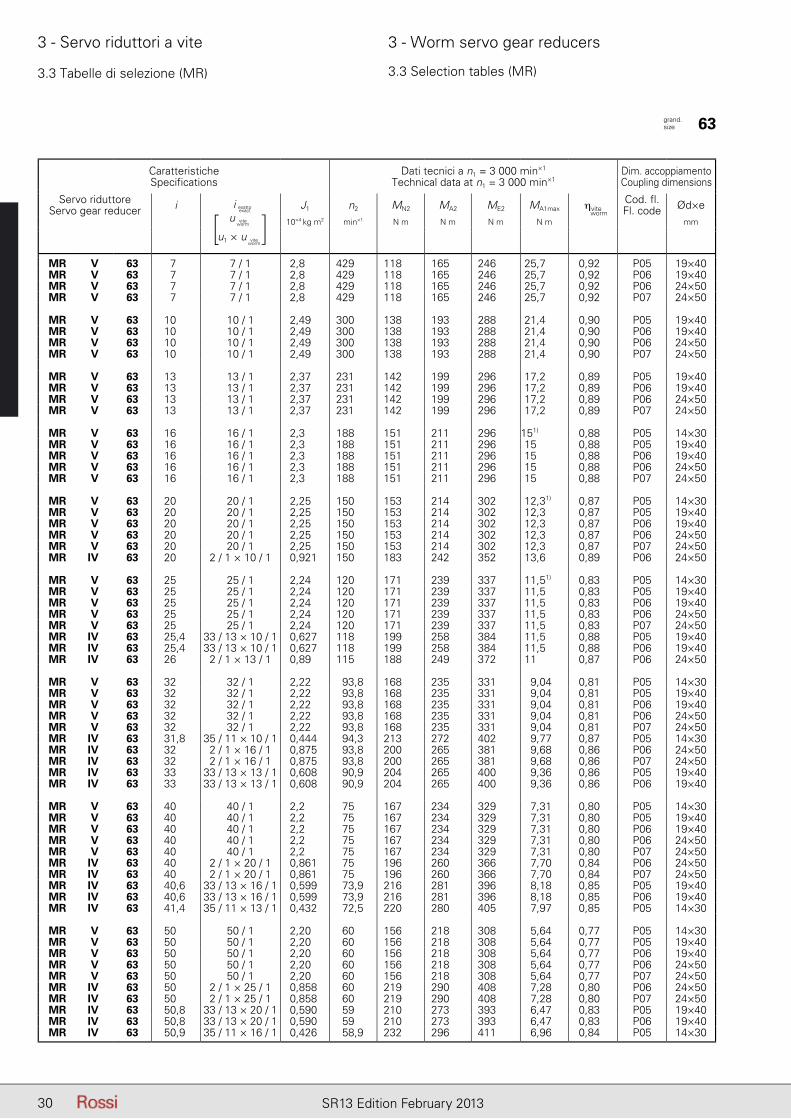
3.3 Tabelle di selezione (MR) 3.3 Selection tables (MR)
CaratteristicheSpecifications
Dati tecnici a n1 = 3 000 min×1
Technical data at n1 = 3 000 min×1Dim. accoppiamento Coupling dimensions
Servo riduttoreServo gear reducer i J1 n2 MN2 MA2 ME2 MA1max ηvite
Cod. fl.Fl. code Ød×e
10×4 kg m2 min×1 N m N m N m N m mm
MR V 63 7 7 / 1 2,8 429 118 165 246 25,7 0,92 P05 19×40MR V 63 7 7 / 1 2,8 429 118 165 246 25,7 0,92 P06 19×40MR V 63 7 7 / 1 2,8 429 118 165 246 25,7 0,92 P06 24×50MR V 63 7 7 / 1 2,8 429 118 165 246 25,7 0,92 P07 24×50
MR V 63 10 10 / 1 2,49 300 138 193 288 21,4 0,90 P05 19×40MR V 63 10 10 / 1 2,49 300 138 193 288 21,4 0,90 P06 19×40MR V 63 10 10 / 1 2,49 300 138 193 288 21,4 0,90 P06 24×50MR V 63 10 10 / 1 2,49 300 138 193 288 21,4 0,90 P07 24×50
MR V 63 13 13 / 1 2,37 231 142 199 296 17,2 0,89 P05 19×40MR V 63 13 13 / 1 2,37 231 142 199 296 17,2 0,89 P06 19×40MR V 63 13 13 / 1 2,37 231 142 199 296 17,2 0,89 P06 24×50MR V 63 13 13 / 1 2,37 231 142 199 296 17,2 0,89 P07 24×50
MR V 63 16 16 / 1 2,3 188 151 211 296 151) 0,88 P05 14×30MR V 63 16 16 / 1 2,3 188 151 211 296 15 0,88 P05 19×40MR V 63 16 16 / 1 2,3 188 151 211 296 15 0,88 P06 19×40MR V 63 16 16 / 1 2,3 188 151 211 296 15 0,88 P06 24×50MR V 63 16 16 / 1 2,3 188 151 211 296 15 0,88 P07 24×50
MR V 63 20 20 / 1 2,25 150 153 214 302 12,31) 0,87 P05 14×30MR V 63 20 20 / 1 2,25 150 153 214 302 12,3 0,87 P05 19×40MR V 63 20 20 / 1 2,25 150 153 214 302 12,3 0,87 P06 19×40MR V 63 20 20 / 1 2,25 150 153 214 302 12,3 0,87 P06 24×50MR V 63 20 20 / 1 2,25 150 153 214 302 12,3 0,87 P07 24×50MR IV 63 20 2 / 1 × 10 / 1 0,921 150 183 242 352 13,6 0,89 P06 24×50
MR V 63 25 25 / 1 2,24 120 171 239 337 11,51) 0,83 P05 14×30MR V 63 25 25 / 1 2,24 120 171 239 337 11,5 0,83 P05 19×40MR V 63 25 25 / 1 2,24 120 171 239 337 11,5 0,83 P06 19×40MR V 63 25 25 / 1 2,24 120 171 239 337 11,5 0,83 P06 24×50MR V 63 25 25 / 1 2,24 120 171 239 337 11,5 0,83 P07 24×50MR IV 63 25,4 33 / 13 × 10 / 1 0,627 118 199 258 384 11,5 0,88 P05 19×40MR IV 63 25,4 33 / 13 × 10 / 1 0,627 118 199 258 384 11,5 0,88 P06 19×40MR IV 63 26 2 / 1 × 13 / 1 0,89 115 188 249 372 11 0,87 P06 24×50
MR V 63 32 32 / 1 2,22 93,8 168 235 331 9,04 0,81 P05 14×30MR V 63 32 32 / 1 2,22 93,8 168 235 331 9,04 0,81 P05 19×40MR V 63 32 32 / 1 2,22 93,8 168 235 331 9,04 0,81 P06 19×40MR V 63 32 32 / 1 2,22 93,8 168 235 331 9,04 0,81 P06 24×50MR V 63 32 32 / 1 2,22 93,8 168 235 331 9,04 0,81 P07 24×50MR IV 63 31,8 35 / 11 × 10 / 1 0,444 94,3 213 272 402 9,77 0,87 P05 14×30MR IV 63 32 2 / 1 × 16 / 1 0,875 93,8 200 265 381 9,68 0,86 P06 24×50MR IV 63 32 2 / 1 × 16 / 1 0,875 93,8 200 265 381 9,68 0,86 P07 24×50MR IV 63 33 33 / 13 × 13 / 1 0,608 90,9 204 265 400 9,36 0,86 P05 19×40MR IV 63 33 33 / 13 × 13 / 1 0,608 90,9 204 265 400 9,36 0,86 P06 19×40
MR V 63 40 40 / 1 2,2 75 167 234 329 7,31 0,80 P05 14×30MR V 63 40 40 / 1 2,2 75 167 234 329 7,31 0,80 P05 19×40MR V 63 40 40 / 1 2,2 75 167 234 329 7,31 0,80 P06 19×40MR V 63 40 40 / 1 2,2 75 167 234 329 7,31 0,80 P06 24×50MR V 63 40 40 / 1 2,2 75 167 234 329 7,31 0,80 P07 24×50MR IV 63 40 2 / 1 × 20 / 1 0,861 75 196 260 366 7,70 0,84 P06 24×50MR IV 63 40 2 / 1 × 20 / 1 0,861 75 196 260 366 7,70 0,84 P07 24×50MR IV 63 40,6 33 / 13 × 16 / 1 0,599 73,9 216 281 396 8,18 0,85 P05 19×40MR IV 63 40,6 33 / 13 × 16 / 1 0,599 73,9 216 281 396 8,18 0,85 P06 19×40MR IV 63 41,4 35 / 11 × 13 / 1 0,432 72,5 220 280 405 7,97 0,85 P05 14×30
MR V 63 50 50 / 1 2,20 60 156 218 308 5,64 0,77 P05 14×30MR V 63 50 50 / 1 2,20 60 156 218 308 5,64 0,77 P05 19×40MR V 63 50 50 / 1 2,20 60 156 218 308 5,64 0,77 P06 19×40MR V 63 50 50 / 1 2,20 60 156 218 308 5,64 0,77 P06 24×50MR V 63 50 50 / 1 2,20 60 156 218 308 5,64 0,77 P07 24×50MR IV 63 50 2 / 1 × 25 / 1 0,858 60 219 290 408 7,28 0,80 P06 24×50MR IV 63 50 2 / 1 × 25 / 1 0,858 60 219 290 408 7,28 0,80 P07 24×50MR IV 63 50,8 33 / 13 × 20 / 1 0,590 59 210 273 393 6,47 0,83 P05 19×40MR IV 63 50,8 33 / 13 × 20 / 1 0,590 59 210 273 393 6,47 0,83 P06 19×40MR IV 63 50,9 35 / 11 × 16 / 1 0,426 58,9 232 296 411 6,96 0,84 P05 14×30
grand. size 63
i esatto
u
u1 × u
viteworm
viteworm
[ ]i esatto
exact worm

31SR13 Edition February 2013
3 - Servo riduttori a vite 3 - Worm servo gear reducers
3.3 Tabelle di selezione (MR) 3.3 Selection tables (MR)
CaratteristicheSpecifications
Dati tecnici a n1 = 3 000 min×1
Technical data at n1 = 3 000 min×1Dim. accoppiamento Coupling dimensions
Servo riduttoreServo gear reducer i J1 n2 MN2 MA2 ME2 MA1max ηvite
Cod. fl.Fl. code Ød×e
10×4 kg m2 min×1 N m N m N m N m mm
MR V 63 63 63 / 1 2,19 47,6 157 220 296 4,69 0,74 P05 14×30MR V 63 63 63 / 1 2,19 47,6 157 220 296 4,69 0,74 P05 19×40MR V 63 63 63 / 1 2,19 47,6 157 220 296 4,69 0,74 P06 19×40MR IV 63 63,5 33 / 13 × 25 / 1 0,588 47,3 237 308 438 6,17 0,79 P05 19×40MR IV 63 63,5 33 / 13 × 25 / 1 0,588 47,3 237 308 438 6,17 0,79 P06 19×40MR IV 63 63,6 35 / 11 × 20 / 1 0,42 47,1 225 287 404 5,48 0,82 P05 14×30MR IV 63 64 2 / 1 × 32 / 1 0,853 46,9 213 282 394 5,69 0,78 P06 24×50MR IV 63 64 2 / 1 × 32 / 1 0,853 46,9 213 282 394 5,69 0,78 P07 24×50
MR IV 63 79,5 35 / 11 × 25 / 1 0,419 37,7 254 323 465 5,28 0,77 P05 14×30MR IV 63 81,2 33 / 13 × 32 / 1 0,585 36,9 228 296 420 4,79 0,76 P05 19×40MR IV 63 81,2 33 / 13 × 32 / 1 0,585 36,9 228 296 420 4,79 0,76 P06 19×40
MR IV 63 102 33 / 13 × 40 / 1 0,583 29,5 221 287 408 3,83 0,74 P05 19×40MR IV 63 102 33 / 13 × 40 / 1 0,583 29,5 221 287 408 3,83 0,74 P06 19×40MR IV 63 102 35 / 11 × 32 / 1 0,417 29,5 243 310 444 4,09 0,75 P05 14×30
MR IV 63 122 19 / 5 × 32 / 1 0,353 24,7 256 320 450 3,6 0,73 P05 14×30MR IV 63 127 33 / 13 × 50 / 1 0,582 23,6 202 263 378 2,91 0,71 P05 19×40MR IV 63 127 33 / 13 × 50 / 1 0,582 23,6 202 263 378 2,91 0,71 P06 19×40
MR IV 63 152 19 / 5 × 40 / 1 0,352 19,7 244 305 432 2,84 0,71 P05 14×30
MR IV 63 190 19 / 5 × 50 / 1 0,352 15,8 220 274 393 2,13 0,68 P05 14×30
MR IV 63 239 19 / 5 × 63 / 1 0,352 12,5 197 230 295 1,5 0,64 P05 14×30
grand. size 63
i esatto
u
u1 × u
viteworm
viteworm
[ ]i esatto
exact worm
1) In caso di albero servo motore senza linguetta MA1max = 10,6 Nm. 1) In case of keyless servo motor shaft end MA1max = 10,6 Nm.

32 SR13 Edition February 2013
3 - Servo riduttori a vite 3 - Worm servo gear reducers
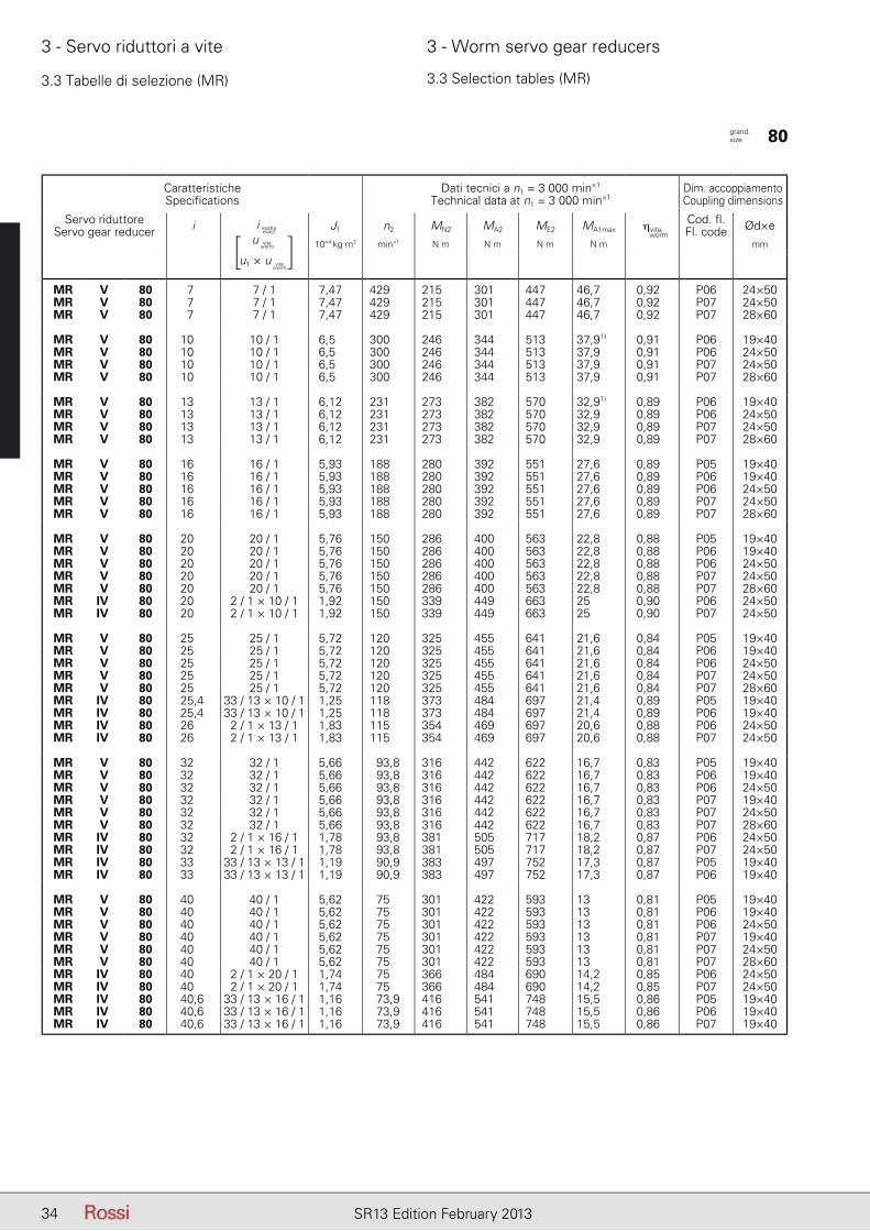
3.3 Tabelle di selezione (MR) 3.3 Selection tables (MR)
CaratteristicheSpecifications
Dati tecnici a n1 = 3 000 min×1
Technical data at n1 = 3 000 min×1Dim. accoppiamento Coupling dimensions
Servo riduttoreServo gear reducer i J1 n2 MN2 MA2 ME2 MA1max ηvite
Cod. fl.Fl. code Ød×e
10×4 kg m2 min×1 N m N m N m N m mm
MR V 64 7 7 / 1 2,8 429 141 197 268 30,8 0,92 P06 19×40MR V 64 7 7 / 1 2,8 429 141 197 268 30,8 0,92 P06 24×50MR V 64 7 7 / 1 2,8 429 141 197 268 30,8 0,92 P07 24×50
MR V 64 10 10 / 1 2,49 300 164 230 313 25,4 0,9 P06 19×40MR V 64 10 10 / 1 2,49 300 164 230 313 25,4 0,9 P06 24×50MR V 64 10 10 / 1 2,49 300 164 230 313 25,4 0,9 P07 24×50
MR V 64 13 13 / 1 2,37 231 169 237 322 20,5 0,89 P05 19×40MR V 64 13 13 / 1 2,37 231 169 237 322 20,5 0,89 P06 19×40MR V 64 13 13 / 1 2,37 231 169 237 322 20,5 0,89 P06 24×50MR V 64 13 13 / 1 2,37 231 169 237 322 20,5 0,89 P07 24×50
MR V 64 16 16 / 1 2,3 188 179 251 322 17,8 0,88 P05 19×40MR V 64 16 16 / 1 2,3 188 179 251 322 17,8 0,88 P06 19×40MR V 64 16 16 / 1 2,3 188 179 251 322 17,8 0,88 P06 24×50MR V 64 16 16 / 1 2,3 188 179 251 322 17,8 0,88 P07 24×50
MR V 64 20 20 / 1 2,25 150 183 256 328 14,7 0,87 P05 19×40MR V 64 20 20 / 1 2,25 150 183 256 328 14,7 0,87 P06 19×40MR V 64 20 20 / 1 2,25 150 183 256 328 14,7 0,87 P06 24×50MR V 64 20 20 / 1 2,25 150 183 256 328 14,7 0,87 P07 24×50MR IV 64 20 2 / 1 × 10 / 1 0,921 150 217 288 383 16,2 0,89 P06 24×50
MR V 64 25 25 / 1 2,24 120 204 286 366 13,7 0,83 P05 19×40MR V 64 25 25 / 1 2,24 120 204 286 366 13,7 0,83 P06 19×40MR V 64 25 25 / 1 2,24 120 204 286 366 13,7 0,83 P06 24×50MR V 64 25 25 / 1 2,24 120 204 286 366 13,7 0,83 P07 24×50MR IV 64 25,4 33 / 13 × 10 / 1 0,627 118 236 307 418 13,7 0,88 P05 19×40MR IV 64 25,4 33 / 13 × 10 / 1 0,627 118 236 307 418 13,7 0,88 P06 19×40MR IV 64 26 2 / 1 × 13 / 1 0,89 115 223 296 404 13,1 0,87 P06 24×50
MR V 64 32 32 / 1 2,22 93,8 200 280 360 10,81) 0,81 P05 14×30MR V 64 32 32 / 1 2,22 93,8 200 280 360 10,8 0,81 P05 19×40MR V 64 32 32 / 1 2,22 93,8 200 280 360 10,8 0,81 P06 19×40MR V 64 32 32 / 1 2,22 93,8 200 280 360 10,8 0,81 P06 24×50MR V 64 32 32 / 1 2,22 93,8 200 280 360 10,8 0,81 P07 24×50MR IV 64 31,8 35 / 11 × 10 / 1 0,444 94,3 254 323 436 11,6 0,87 P05 14×30MR IV 64 32 2 / 1 × 16 / 1 0,875 93,8 238 315 413 11,5 0,86 P06 24×50MR IV 64 32 2 / 1 × 16 / 1 0,875 93,8 238 315 413 11,5 0,86 P07 24×50MR IV 64 33 33 / 13 × 13 / 1 0,608 90,9 243 316 434 11,1 0,86 P05 19×40MR IV 64 33 33 / 13 × 13 / 1 0,608 90,9 243 316 434 11,1 0,86 P06 19×40
MR V 64 40 40 / 1 2,2 75 199 278 357 8,7 0,8 P05 14×30MR V 64 40 40 / 1 2,2 75 199 278 357 8,7 0,8 P05 19×40MR V 64 40 40 / 1 2,2 75 199 278 357 8,7 0,8 P06 19×40MR V 64 40 40 / 1 2,2 75 199 278 357 8,7 0,8 P07 24×50MR V 64 40 40 / 1 2,2 75 199 278 357 8,7 0,8 P07 24×50MR IV 64 40 2 / 1 × 20 / 1 0,861 75 233 309 398 9,16 0,84 P06 24×50MR IV 64 40 2 / 1 × 20 / 1 0,861 75 233 309 398 9,16 0,84 P07 24×50MR IV 64 40,6 33 / 13 × 16 / 1 0,599 73,9 257 335 430 9,74 0,85 P05 19×40MR IV 64 40,6 33 / 13 × 16 / 1 0,599 73,9 257 335 430 9,74 0,85 P06 19×40MR IV 64 41,4 35 / 11 × 13 / 1 0,432 72,5 261 333 440 9,48 0,85 P05 14×30
MR V 64 50 50 / 1 2,2 60 186 260 334 6,73 0,77 P05 14×30MR V 64 50 50 / 1 2,2 60 186 260 334 6,73 0,77 P05 19×40MR V 64 50 50 / 1 2,2 60 186 260 334 6,73 0,77 P06 19×40MR V 64 50 50 / 1 2,2 60 186 260 334 6,73 0,77 P06 24×50MR V 64 50 50 / 1 2,2 60 186 260 334 6,73 0,77 P07 24×50MR IV 64 50 2 / 1 × 25 / 1 0,858 60 261 346 444 8,66 0,8 P06 24×50MR IV 64 50 2 / 1 × 25 / 1 0,858 60 261 346 444 8,66 0,8 P07 24×50MR IV 64 50,8 33 / 13 × 20 / 1 0,590 59 250 325 427 7,7 0,83 P05 19×40MR IV 64 50,8 33 / 13 × 20 / 1 0,590 59 250 325 427 7,7 0,83 P06 19×40MR IV 64 50,9 35 / 11 × 16 / 1 0,426 58,9 276 352 446 8,28 0,84 P05 14×30
grand. size 64
i esatto
u
u1 × u
viteworm
viteworm
[ ]i esatto
exact worm

33SR13 Edition February 2013
3 - Servo riduttori a vite 3 - Worm servo gear reducers
3.3 Tabelle di selezione (MR) 3.3 Selection tables (MR)
CaratteristicheSpecifications
Dati tecnici a n1 = 3 000 min×1
Technical data at n1 = 3 000 min×1Dim. accoppiamento Coupling dimensions
Servo riduttoreServo gear reducer i J1 n2 MN2 MA2 ME2 MA1max ηvite
Cod. fl.Fl. code Ød×e
10×4 kg m2 min×1 N m N m N m N m mm
MR V 64 63 63 / 1 2,19 47,6 187 256 331 5,46 0,74 P05 14×30MR V 64 63 63 / 1 2,19 47,6 187 256 331 5,46 0,74 P05 19×40MR V 64 63 63 / 1 2,19 47,6 187 256 331 5,46 0,74 P06 19×40MR V 64 63 63 / 1 2,19 47,6 187 256 331 5,46 0,74 P06 24×50MR V 64 63 63 / 1 2,19 47,6 187 256 331 5,46 0,74 P07 24×50MR IV 64 63,5 33 / 13 × 25 / 1 0,588 47,3 282 366 475 7,34 0,79 P05 19×40MR IV 64 63,5 33 / 13 × 25 / 1 0,588 47,3 282 366 475 7,34 0,79 P06 19×40MR IV 64 63,6 35 / 11 × 20 / 1 0,42 47,1 267 341 438 6,52 0,82 P05 14×30MR IV 64 64 2 / 1 × 32 / 1 0,853 46,9 254 336 428 6,77 0,78 P06 24×50MR IV 64 64 2 / 1 × 32 / 1 0,853 46,9 254 336 428 6,77 0,78 P07 24×50
MR IV 64 79,5 35 / 11 × 25 / 1 0,419 37,7 302 385 505 6,28 0,77 P05 14×30MR IV 64 81,2 33 / 13 × 32 / 1 0,585 36,9 271 352 456 5,70 0,76 P05 19×40MR IV 64 81,2 33 / 13 × 32 / 1 0,585 36,9 271 352 456 5,70 0,76 P06 19×40
MR IV 64 102 33 / 13 × 40 / 1 0,583 29,5 263 342 443 4,56 0,74 P05 19×40MR IV 64 102 33 / 13 × 40 / 1 0,583 29,5 263 342 443 4,56 0,74 P06 19×40MR IV 64 102 35 / 11 × 32 / 1 0,417 29,5 290 369 483 4,86 0,75 P05 14×30
MR IV 64 122 19 / 5 × 32 / 1 0,353 24,7 305 378 489 4,26 0,73 P05 14×30MR IV 64 127 33 / 13 × 50 / 1 0,582 23,6 241 312 411 3,46 0,71 P05 19×40MR IV 64 127 33 / 13 × 50 / 1 0,582 23,6 241 312 411 3,46 0,71 P06 19×40
MR IV 64 152 19 / 5 × 40 / 1 0,352 19,7 291 344 469 3,19 0,71 P05 14×30
MR IV 64 190 19 / 5 × 50 / 1 0,352 15,8 261 312 440 2,42 0,68 P05 14×30
MR IV 64 239 19 / 5 × 63 / 1 0,352 12,5 221 256 330 1,67 0,64 P05 14×30
grand. size 64
i esatto
u
u1 × u
viteworm
viteworm
[ ]i esatto
exact worm
1) In caso di albero servo motore senza linguetta MA1max = 10,6 Nm. 1) In case of keyless servo motor shaft end MA1max = 10,6 Nm.
34 SR13 Edition February 2013
3 - Servo riduttori a vite 3 - Worm servo gear reducers
3.3 Tabelle di selezione (MR) 3.3 Selection tables (MR)
CaratteristicheSpecifications
Dati tecnici a n1 = 3 000 min×1
Technical data at n1 = 3 000 min×1Dim. accoppiamento Coupling dimensions
Servo riduttoreServo gear reducer i J1 n2 MN2 MA2 ME2 MA1max ηvite
Cod. fl.Fl. code Ød×e
10×4 kg m2 min×1 N m N m N m N m mm
MR V 80 7 7 / 1 7,47 429 215 301 447 46,7 0,92 P06 24×50MR V 80 7 7 / 1 7,47 429 215 301 447 46,7 0,92 P07 24×50MR V 80 7 7 / 1 7,47 429 215 301 447 46,7 0,92 P07 28×60
MR V 80 10 10 / 1 6,5 300 246 344 513 37,91) 0,91 P06 19×40MR V 80 10 10 / 1 6,5 300 246 344 513 37,9 0,91 P06 24×50MR V 80 10 10 / 1 6,5 300 246 344 513 37,9 0,91 P07 24×50MR V 80 10 10 / 1 6,5 300 246 344 513 37,9 0,91 P07 28×60
MR V 80 13 13 / 1 6,12 231 273 382 570 32,91) 0,89 P06 19×40MR V 80 13 13 / 1 6,12 231 273 382 570 32,9 0,89 P06 24×50MR V 80 13 13 / 1 6,12 231 273 382 570 32,9 0,89 P07 24×50MR V 80 13 13 / 1 6,12 231 273 382 570 32,9 0,89 P07 28×60
MR V 80 16 16 / 1 5,93 188 280 392 551 27,6 0,89 P05 19×40MR V 80 16 16 / 1 5,93 188 280 392 551 27,6 0,89 P06 19×40MR V 80 16 16 / 1 5,93 188 280 392 551 27,6 0,89 P06 24×50MR V 80 16 16 / 1 5,93 188 280 392 551 27,6 0,89 P07 24×50MR V 80 16 16 / 1 5,93 188 280 392 551 27,6 0,89 P07 28×60
MR V 80 20 20 / 1 5,76 150 286 400 563 22,8 0,88 P05 19×40MR V 80 20 20 / 1 5,76 150 286 400 563 22,8 0,88 P06 19×40MR V 80 20 20 / 1 5,76 150 286 400 563 22,8 0,88 P06 24×50MR V 80 20 20 / 1 5,76 150 286 400 563 22,8 0,88 P07 24×50MR V 80 20 20 / 1 5,76 150 286 400 563 22,8 0,88 P07 28×60MR IV 80 20 2 / 1 × 10 / 1 1,92 150 339 449 663 25 0,90 P06 24×50MR IV 80 20 2 / 1 × 10 / 1 1,92 150 339 449 663 25 0,90 P07 24×50
MR V 80 25 25 / 1 5,72 120 325 455 641 21,6 0,84 P05 19×40MR V 80 25 25 / 1 5,72 120 325 455 641 21,6 0,84 P06 19×40MR V 80 25 25 / 1 5,72 120 325 455 641 21,6 0,84 P06 24×50MR V 80 25 25 / 1 5,72 120 325 455 641 21,6 0,84 P07 24×50MR V 80 25 25 / 1 5,72 120 325 455 641 21,6 0,84 P07 28×60MR IV 80 25,4 33 / 13 × 10 / 1 1,25 118 373 484 697 21,4 0,89 P05 19×40MR IV 80 25,4 33 / 13 × 10 / 1 1,25 118 373 484 697 21,4 0,89 P06 19×40MR IV 80 26 2 / 1 × 13 / 1 1,83 115 354 469 697 20,6 0,88 P06 24×50MR IV 80 26 2 / 1 × 13 / 1 1,83 115 354 469 697 20,6 0,88 P07 24×50
MR V 80 32 32 / 1 5,66 93,8 316 442 622 16,7 0,83 P05 19×40MR V 80 32 32 / 1 5,66 93,8 316 442 622 16,7 0,83 P06 19×40MR V 80 32 32 / 1 5,66 93,8 316 442 622 16,7 0,83 P06 24×50MR V 80 32 32 / 1 5,66 93,8 316 442 622 16,7 0,83 P07 19×40MR V 80 32 32 / 1 5,66 93,8 316 442 622 16,7 0,83 P07 24×50MR V 80 32 32 / 1 5,66 93,8 316 442 622 16,7 0,83 P07 28×60MR IV 80 32 2 / 1 × 16 / 1 1,78 93,8 381 505 717 18,2 0,87 P06 24×50MR IV 80 32 2 / 1 × 16 / 1 1,78 93,8 381 505 717 18,2 0,87 P07 24×50MR IV 80 33 33 / 13 × 13 / 1 1,19 90,9 383 497 752 17,3 0,87 P05 19×40MR IV 80 33 33 / 13 × 13 / 1 1,19 90,9 383 497 752 17,3 0,87 P06 19×40
MR V 80 40 40 / 1 5,62 75 301 422 593 13 0,81 P05 19×40MR V 80 40 40 / 1 5,62 75 301 422 593 13 0,81 P06 19×40MR V 80 40 40 / 1 5,62 75 301 422 593 13 0,81 P06 24×50MR V 80 40 40 / 1 5,62 75 301 422 593 13 0,81 P07 19×40MR V 80 40 40 / 1 5,62 75 301 422 593 13 0,81 P07 24×50MR V 80 40 40 / 1 5,62 75 301 422 593 13 0,81 P07 28×60MR IV 80 40 2 / 1 × 20 / 1 1,74 75 366 484 690 14,2 0,85 P06 24×50MR IV 80 40 2 / 1 × 20 / 1 1,74 75 366 484 690 14,2 0,85 P07 24×50MR IV 80 40,6 33 / 13 × 16 / 1 1,16 73,9 416 541 748 15,5 0,86 P05 19×40MR IV 80 40,6 33 / 13 × 16 / 1 1,16 73,9 416 541 748 15,5 0,86 P06 19×40MR IV 80 40,6 33 / 13 × 16 / 1 1,16 73,9 416 541 748 15,5 0,86 P07 19×40
grand. size 80
i esatto
u
u1 × u
viteworm
viteworm
[ ]i esatto
exact worm
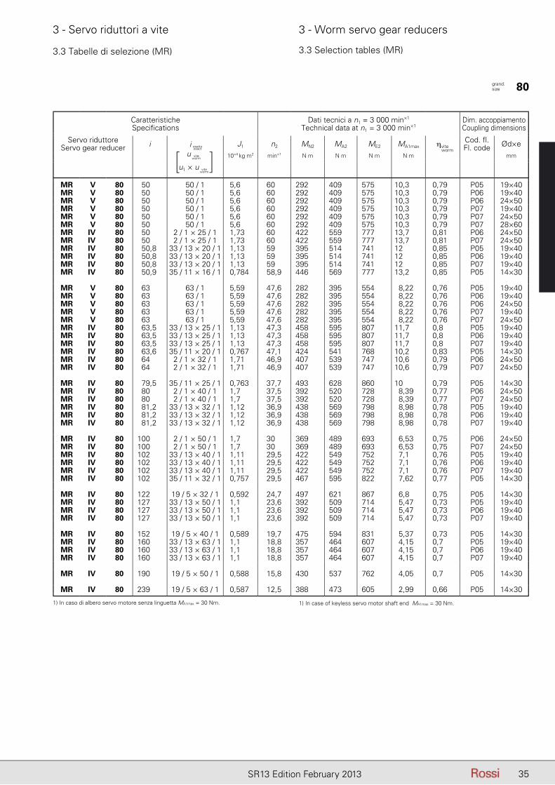
35SR13 Edition February 2013
3 - Servo riduttori a vite 3 - Worm servo gear reducers
3.3 Tabelle di selezione (MR) 3.3 Selection tables (MR)
CaratteristicheSpecifications
Dati tecnici a n1 = 3 000 min×1
Technical data at n1 = 3 000 min×1Dim. accoppiamento Coupling dimensions
Servo riduttoreServo gear reducer i J1 n2 MN2 MA2 ME2 MA1max ηvite
Cod. fl.Fl. code Ød×e
10×4 kg m2 min×1 N m N m N m N m mm
MR V 80 50 50 / 1 5,6 60 292 409 575 10,3 0,79 P05 19×40MR V 80 50 50 / 1 5,6 60 292 409 575 10,3 0,79 P06 19×40MR V 80 50 50 / 1 5,6 60 292 409 575 10,3 0,79 P06 24×50MR V 80 50 50 / 1 5,6 60 292 409 575 10,3 0,79 P07 19×40MR V 80 50 50 / 1 5,6 60 292 409 575 10,3 0,79 P07 24×50MR V 80 50 50 / 1 5,6 60 292 409 575 10,3 0,79 P07 28×60MR IV 80 50 2 / 1 × 25 / 1 1,73 60 422 559 777 13,7 0,81 P06 24×50MR IV 80 50 2 / 1 × 25 / 1 1,73 60 422 559 777 13,7 0,81 P07 24×50MR IV 80 50,8 33 / 13 × 20 / 1 1,13 59 395 514 741 12 0,85 P05 19×40MR IV 80 50,8 33 / 13 × 20 / 1 1,13 59 395 514 741 12 0,85 P06 19×40MR IV 80 50,8 33 / 13 × 20 / 1 1,13 59 395 514 741 12 0,85 P07 19×40MR IV 80 50,9 35 / 11 × 16 / 1 0,784 58,9 446 569 777 13,2 0,85 P05 14×30
MR V 80 63 63 / 1 5,59 47,6 282 395 554 8,22 0,76 P05 19×40MR V 80 63 63 / 1 5,59 47,6 282 395 554 8,22 0,76 P06 19×40MR V 80 63 63 / 1 5,59 47,6 282 395 554 8,22 0,76 P06 24×50MR V 80 63 63 / 1 5,59 47,6 282 395 554 8,22 0,76 P07 19×40MR V 80 63 63 / 1 5,59 47,6 282 395 554 8,22 0,76 P07 24×50MR IV 80 63,5 33 / 13 × 25 / 1 1,13 47,3 458 595 807 11,7 0,8 P05 19×40MR IV 80 63,5 33 / 13 × 25 / 1 1,13 47,3 458 595 807 11,7 0,8 P06 19×40MR IV 80 63,5 33 / 13 × 25 / 1 1,13 47,3 458 595 807 11,7 0,8 P07 19×40MR IV 80 63,6 35 / 11 × 20 / 1 0,767 47,1 424 541 768 10,2 0,83 P05 14×30MR IV 80 64 2 / 1 × 32 / 1 1,71 46,9 407 539 747 10,6 0,79 P06 24×50MR IV 80 64 2 / 1 × 32 / 1 1,71 46,9 407 539 747 10,6 0,79 P07 24×50
MR IV 80 79,5 35 / 11 × 25 / 1 0,763 37,7 493 628 860 10 0,79 P05 14×30MR IV 80 80 2 / 1 × 40 / 1 1,7 37,5 392 520 728 8,39 0,77 P06 24×50MR IV 80 80 2 / 1 × 40 / 1 1,7 37,5 392 520 728 8,39 0,77 P07 24×50MR IV 80 81,2 33 / 13 × 32 / 1 1,12 36,9 438 569 798 8,98 0,78 P05 19×40MR IV 80 81,2 33 / 13 × 32 / 1 1,12 36,9 438 569 798 8,98 0,78 P06 19×40MR IV 80 81,2 33 / 13 × 32 / 1 1,12 36,9 438 569 798 8,98 0,78 P07 19×40
MR IV 80 100 2 / 1 × 50 / 1 1,7 30 369 489 693 6,53 0,75 P06 24×50MR IV 80 100 2 / 1 × 50 / 1 1,7 30 369 489 693 6,53 0,75 P07 24×50MR IV 80 102 33 / 13 × 40 / 1 1,11 29,5 422 549 752 7,1 0,76 P05 19×40MR IV 80 102 33 / 13 × 40 / 1 1,11 29,5 422 549 752 7,1 0,76 P06 19×40MR IV 80 102 33 / 13 × 40 / 1 1,11 29,5 422 549 752 7,1 0,76 P07 19×40MR IV 80 102 35 / 11 × 32 / 1 0,757 29,5 467 595 822 7,62 0,77 P05 14×30
MR IV 80 122 19 / 5 × 32 / 1 0,592 24,7 497 621 867 6,8 0,75 P05 14×30MR IV 80 127 33 / 13 × 50 / 1 1,1 23,6 392 509 714 5,47 0,73 P05 19×40MR IV 80 127 33 / 13 × 50 / 1 1,1 23,6 392 509 714 5,47 0,73 P06 19×40MR IV 80 127 33 / 13 × 50 / 1 1,1 23,6 392 509 714 5,47 0,73 P07 19×40
MR IV 80 152 19 / 5 × 40 / 1 0,589 19,7 475 594 831 5,37 0,73 P05 14×30MR IV 80 160 33 / 13 × 63 / 1 1,1 18,8 357 464 607 4,15 0,7 P05 19×40MR IV 80 160 33 / 13 × 63 / 1 1,1 18,8 357 464 607 4,15 0,7 P06 19×40MR IV 80 160 33 / 13 × 63 / 1 1,1 18,8 357 464 607 4,15 0,7 P07 19×40
MR IV 80 190 19 / 5 × 50 / 1 0,588 15,8 430 537 762 4,05 0,7 P05 14×30
MR IV 80 239 19 / 5 × 63 / 1 0,587 12,5 388 473 605 2,99 0,66 P05 14×30
grand. size 80
i esatto
u
u1 × u
viteworm
viteworm
[ ]i esatto
exact worm
1) In caso di albero servo motore senza linguetta MA1max = 30 Nm. 1) In case of keyless servo motor shaft end MA1max = 30 Nm.
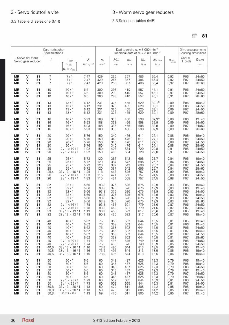
36 SR13 Edition February 2013
3 - Servo riduttori a vite 3 - Worm servo gear reducers
3.3 Tabelle di selezione (MR) 3.3 Selection tables (MR)
CaratteristicheSpecifications
Dati tecnici a n1 = 3 000 min×1
Technical data at n1 = 3 000 min×1Dim. accoppiamento Coupling dimensions
Servo riduttoreServo gear reducer i J1 n2 MN2 MA2 ME2 MA1max ηvite
Cod. fl.Fl. code Ød×e
10×4 kg m2 min×1 N m N m N m N m mm
MR V 81 7 7 / 1 7,47 429 255 357 486 55,4 0,92 P06 24×50MR V 81 7 7 / 1 7,47 429 255 357 486 55,4 0,92 P07 24×50MR V 81 7 7 / 1 7,47 429 255 357 486 55,4 0,92 P07 28×60
MR V 81 10 10 / 1 6,5 300 293 410 557 45,1 0,91 P06 24×50MR V 81 10 10 / 1 6,5 300 293 410 557 45,1 0,91 P07 24×50MR V 81 10 10 / 1 6,5 300 293 410 557 45,1 0,91 P07 28×60
MR V 81 13 13 / 1 6,12 231 325 455 620 39,11) 0,89 P06 19×40MR V 81 13 13 / 1 6,12 231 325 455 620 39,1 0,89 P06 24×50MR V 81 13 13 / 1 6,12 231 325 455 620 39,1 0,89 P07 24×50MR V 81 13 13 / 1 6,12 231 325 455 620 39,1 0,89 P07 28×60
MR V 81 16 16 / 1 5,93 188 333 466 598 32,91) 0,89 P06 19×40MR V 81 16 16 / 1 5,93 188 333 466 598 32,9 0,89 P06 24×50MR V 81 16 16 / 1 5,93 188 333 466 598 32,9 0,89 P07 24×50MR V 81 16 16 / 1 5,93 188 333 466 598 32,9 0,89 P07 28×60
MR V 81 20 20 / 1 5,76 150 340 476 611 27,1 0,88 P06 19×40MR V 81 20 20 / 1 5,76 150 340 476 611 27,1 0,88 P06 24×50MR V 81 20 20 / 1 5,76 150 340 476 611 27,1 0,88 P07 24×50MR V 81 20 20 / 1 5,76 150 340 476 611 27,1 0,88 P07 28×60MR IV 81 20 2 / 1 × 10 / 1 1,92 150 403 534 720 29,8 0,9 P06 24×50MR IV 81 20 2 / 1 × 10 / 1 1,92 150 403 534 720 29,8 0,9 P07 24×50
MR V 81 25 25 / 1 5,72 120 387 542 696 25,7 0,84 P06 19×40MR V 81 25 25 / 1 5,72 120 387 542 696 25,7 0,84 P06 24×50MR V 81 25 25 / 1 5,72 120 387 542 696 25,7 0,84 P07 24×50MR V 81 25 25 / 1 5,72 120 387 542 696 25,7 0,84 P07 28×60MR IV 81 25,4 33 / 13 × 10 / 1 1,25 118 443 576 757 25,5 0,89 P06 19×40MR IV 81 26 2 / 1 × 13 / 1 1,83 115 421 558 757 24,5 0,88 P06 24×50MR IV 81 26 2 / 1 × 13 / 1 1,83 115 421 558 757 24,5 0,88 P07 24×50
MR V 81 32 32 / 1 5,66 93,8 376 526 675 19,9 0,83 P05 19×40MR V 81 32 32 / 1 5,66 93,8 376 526 675 19,9 0,83 P06 19×40MR V 81 32 32 / 1 5,66 93,8 376 526 675 19,9 0,83 P06 24×50MR V 81 32 32 / 1 5,66 93,8 376 526 675 19,9 0,83 P07 19×40MR V 81 32 32 / 1 5,66 93,8 376 526 675 19,9 0,83 P07 24×50MR V 81 32 32 / 1 5,66 93,8 376 526 675 19,9 0,83 P07 28×60MR IV 81 32 2 / 1 × 16 / 1 1,78 93,8 453 601 779 21,6 0,87 P06 24×50MR IV 81 32 2 / 1 × 16 / 1 1,78 93,8 453 601 779 21,6 0,87 P07 24×50MR IV 81 33 33 / 13 × 13 / 1 1,19 90,9 455 592 817 20,6 0,87 P05 19×40MR IV 81 33 33 / 13 × 13 / 1 1,19 90,9 455 592 817 20,6 0,87 P06 19×40
MR V 81 40 40 / 1 5,62 75 358 502 644 15,5 0,81 P05 19×40MR V 81 40 40 / 1 5,62 75 358 502 644 15,5 0,81 P06 19×40MR V 81 40 40 / 1 5,62 75 358 502 644 15,5 0,81 P06 24×50MR V 81 40 40 / 1 5,62 75 358 502 644 15,5 0,81 P07 19×40MR V 81 40 40 / 1 5,62 75 358 502 644 15,5 0,81 P07 24×50MR V 81 40 40 / 1 5,62 75 358 502 644 15,5 0,81 P07 28×60MR IV 81 40 2 / 1 × 20 / 1 1,74 75 435 576 749 16,9 0,85 P06 24×50MR IV 81 40 2 / 1 × 20 / 1 1,74 75 435 576 749 16,9 0,85 P07 24×50MR IV 81 40,6 33 / 13 × 16 / 1 1,16 73,9 495 644 813 18,5 0,86 P05 19×40MR IV 81 40,6 33 / 13 × 16 / 1 1,16 73,9 495 644 813 18,5 0,86 P06 19×40MR IV 81 40,6 33 / 13 × 16 / 1 1,16 73,9 495 644 813 18,5 0,86 P07 19×40
MR V 81 50 50 / 1 5,6 60 348 487 625 12,3 0,79 P05 19×40MR V 81 50 50 / 1 5,6 60 348 487 625 12,3 0,79 P06 19×40MR V 81 50 50 / 1 5,6 60 348 487 625 12,3 0,79 P06 24×50MR V 81 50 50 / 1 5,6 60 348 487 625 12,3 0,79 P07 19×40MR V 81 50 50 / 1 5,6 60 348 487 625 12,3 0,79 P07 24×50MR V 81 50 50 / 1 5,6 60 348 487 625 12,3 0,79 P07 28×60MR IV 81 50 2 / 1 × 25 / 1 1,73 60 502 665 844 16,3 0,81 P06 24×50MR IV 81 50 2 / 1 × 25 / 1 1,73 60 502 665 844 16,3 0,81 P07 24×50MR IV 81 50,8 33 / 13 × 20 / 1 1,13 59 470 611 805 14,2 0,85 P05 19×40MR IV 81 50,8 33 / 13 × 20 / 1 1,13 59 470 611 805 14,2 0,85 P06 19×40MR IV 81 50,8 33 / 13 × 20 / 1 1,13 59 470 611 805 14,2 0,85 P07 19×40
grand. size 81
i esatto
u
u1 × u
viteworm
viteworm
[ ]i esatto
exact worm
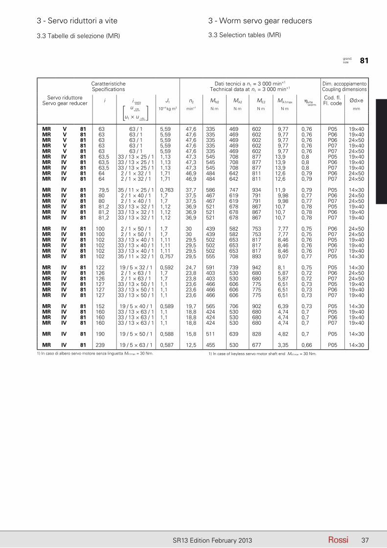
37SR13 Edition February 2013
3 - Servo riduttori a vite 3 - Worm servo gear reducers
3.3 Tabelle di selezione (MR) 3.3 Selection tables (MR)
CaratteristicheSpecifications
Dati tecnici a n1 = 3 000 min×1
Technical data at n1 = 3 000 min×1Dim. accoppiamento Coupling dimensions
Servo riduttoreServo gear reducer i J1 n2 MN2 MA2 ME2 MA1max ηvite
Cod. fl.Fl. code Ød×e
10×4 kg m2 min×1 N m N m N m N m mm
MR V 81 63 63 / 1 5,59 47,6 335 469 602 9,77 0,76 P05 19×40MR V 81 63 63 / 1 5,59 47,6 335 469 602 9,77 0,76 P06 19×40MR V 81 63 63 / 1 5,59 47,6 335 469 602 9,77 0,76 P06 24×50MR V 81 63 63 / 1 5,59 47,6 335 469 602 9,77 0,76 P07 19×40MR V 81 63 63 / 1 5,59 47,6 335 469 602 9,77 0,76 P07 24×50MR IV 81 63,5 33 / 13 × 25 / 1 1,13 47,3 545 708 877 13,9 0,8 P05 19×40MR IV 81 63,5 33 / 13 × 25 / 1 1,13 47,3 545 708 877 13,9 0,8 P06 19×40MR IV 81 63,5 33 / 13 × 25 / 1 1,13 47,3 545 708 877 13,9 0,8 P07 19×40MR IV 81 64 2 / 1 × 32 / 1 1,71 46,9 484 642 811 12,6 0,79 P06 24×50MR IV 81 64 2 / 1 × 32 / 1 1,71 46,9 484 642 811 12,6 0,79 P07 24×50
MR IV 81 79,5 35 / 11 × 25 / 1 0,763 37,7 586 747 934 11,9 0,79 P05 14×30MR IV 81 80 2 / 1 × 40 / 1 1,7 37,5 467 619 791 9,98 0,77 P06 24×50MR IV 81 80 2 / 1 × 40 / 1 1,7 37,5 467 619 791 9,98 0,77 P07 24×50MR IV 81 81,2 33 / 13 × 32 / 1 1,12 36,9 521 678 867 10,7 0,78 P05 19×40MR IV 81 81,2 33 / 13 × 32 / 1 1,12 36,9 521 678 867 10,7 0,78 P06 19×40MR IV 81 81,2 33 / 13 × 32 / 1 1,12 36,9 521 678 867 10,7 0,78 P07 19×40
MR IV 81 100 2 / 1 × 50 / 1 1,7 30 439 582 753 7,77 0,75 P06 24×50MR IV 81 100 2 / 1 × 50 / 1 1,7 30 439 582 753 7,77 0,75 P07 24×50MR IV 81 102 33 / 13 × 40 / 1 1,11 29,5 502 653 817 8,46 0,76 P05 19×40MR IV 81 102 33 / 13 × 40 / 1 1,11 29,5 502 653 817 8,46 0,76 P06 19×40MR IV 81 102 33 / 13 × 40 / 1 1,11 29,5 502 653 817 8,46 0,76 P07 19×40MR IV 81 102 35 / 11 × 32 / 1 0,757 29,5 555 708 893 9,07 0,77 P05 14×30
MR IV 81 122 19 / 5 × 32 / 1 0,592 24,7 591 739 942 8,1 0,75 P05 14×30MR IV 81 126 2 / 1 × 63 / 1 1,7 23,8 403 530 680 5,87 0,72 P06 24×50MR IV 81 126 2 / 1 × 63 / 1 1,7 23,8 403 530 680 5,87 0,72 P07 24×50MR IV 81 127 33 / 13 × 50 / 1 1,1 23,6 466 606 775 6,51 0,73 P05 19×40MR IV 81 127 33 / 13 × 50 / 1 1,1 23,6 466 606 775 6,51 0,73 P06 19×40MR IV 81 127 33 / 13 × 50 / 1 1,1 23,6 466 606 775 6,51 0,73 P07 19×40
MR IV 81 152 19 / 5 × 40 / 1 0,589 19,7 565 706 902 6,39 0,73 P05 14×30MR IV 81 160 33 / 13 × 63 / 1 1,1 18,8 424 530 680 4,74 0,7 P05 19×40MR IV 81 160 33 / 13 × 63 / 1 1,1 18,8 424 530 680 4,74 0,7 P06 19×40MR IV 81 160 33 / 13 × 63 / 1 1,1 18,8 424 530 680 4,74 0,7 P07 19×40
MR IV 81 190 19 / 5 × 50 / 1 0,588 15,8 511 639 828 4,82 0,7 P05 14×30
MR IV 81 239 19 / 5 × 63 / 1 0,587 12,5 455 530 677 3,35 0,66 P05 14×30
grand. size 81
i esatto
u
u1 × u
viteworm
viteworm
[ ]i esatto
exact worm
1) In caso di albero servo motore senza linguetta MA1max = 30 Nm. 1) In case of keyless servo motor shaft end MA1max = 30 Nm.
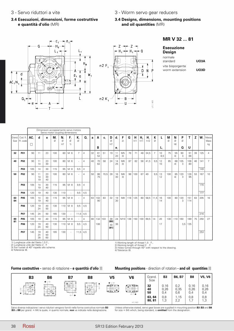
38 SR13 Edition February 2013
3 - Servo riduttori a vite 3 - Worm servo gear reducers3.4 Esecuzioni, dimensioni, forme costruttive
e quantità d'olio (MR)3.4 Designs, dimensions, mounting positions
and oil quantities (MR)
MR V 32 ... 81
Grand.Size
B3 B6, B7 B8 V5, V6
32 0.16 0,2 0,16 0,1640 0,26 0,35 0,26 0,2650 0,4 0,6 0,4 0,463, 64 0,8 1,15 0,8 0,880, 81 1,3 2,2 1,7 1,3
Salvo diversa indicazione i servo riduttori vengono forniti nella forma costruttiva normale B3 (B3 e B8 per grand. � 64) la quale, in quanto normale, non va indicata nella designazione.
Unless otherwise stated, servo gear boxes are supplied in mounting position B3 (B3 and B8 for size � 64) which, being standard, is omitted from the designation.
Forme costruttive - senso di rotazione - e quantità d’olio [l] Mounting positions - direction of rotation - and oil quantities [l]
Dimensioni accoppiamento servo motoreServo motor coupling dimensions
Grand. Cod. fl. AC1 d e M1 N1 F1 K1 Q1 a A c1 D d1 F G H H0 H1 K L M N P T Z W1 MassaSize Fl. code Ø Ø Ø Ø Ø 2) h11 h11 h12 Ø Ø Ø Ø Mass
H7 1) H7 h6 kgB e1 L1 Q U
32 P01 90 11 23 100 80 M06 7 4 32 61 51 19 11 M5 76 71 48 34,5 7 10 75 55 90 91 39 125 452 20 3) 8,5 4) 3 66
40 P02 90 11 23 100 80 M06 - 4 40 70 58 24 14 M6 87 82 56 41,5 9,5 12 85 68 105 106 46 141 714 30 62 25 3) 10 4) 3 80
P03 105 14 30 115 95 M08 9,5 4 149
50 P02 90 11 23 100 80 M06 - 4 50 86 70,5 28 16 M6 98 100 67 49 9,5 13 100 85 120 126 53 167 1014 30 75 30 3) 12 4) 3 9519 40
P03 105 14 30 115 95 M08 9,5 4 17019 40
P04 120 19 40 130 110 - 9,5 4,5 177
63 P05 105 14 30 115 95 M08 - 4 63 102 83 32 19 M8 118 125 80 58,5 11,5 16 100 80 120 151 63 205 1664 19 40 90 30 14 3 114
P06 120 19 40 130 110 M08 9,5 4,524 50
P07 145 24 50 165 130 - 11,5 4,5 216
80 P05 105 19 40 115 95 M08 - 4 80 132 103 38 24 M10 138 150 100 69,5 14 20 130 110 160 189 75 250 2781
P06 120 19 40 130 110 M08 9,5 4,5 106(80)
36 17 3,5 13524 50
40
P07 145 19 40 165 130 - 11,5 4,5
(81)
25324 5028 60
B3 B6 B7 B8 V5 V6
EsecuzioneDesignnormale standard UO3A
vite bisporgente worm extension UO3D
1) Lunghezza utile del filetto 1,5 F1.2) Lunghezza utile del filetto 2 · F.3) Fori ruotati di 45° rispetto allo schema.4) Tolleranza t8.
1) Working length of thread 1,5 · F1.2) Working length of thread 2 · F.3) Holes turned through 45° with respect to the drawing.4) Tolerance t8.
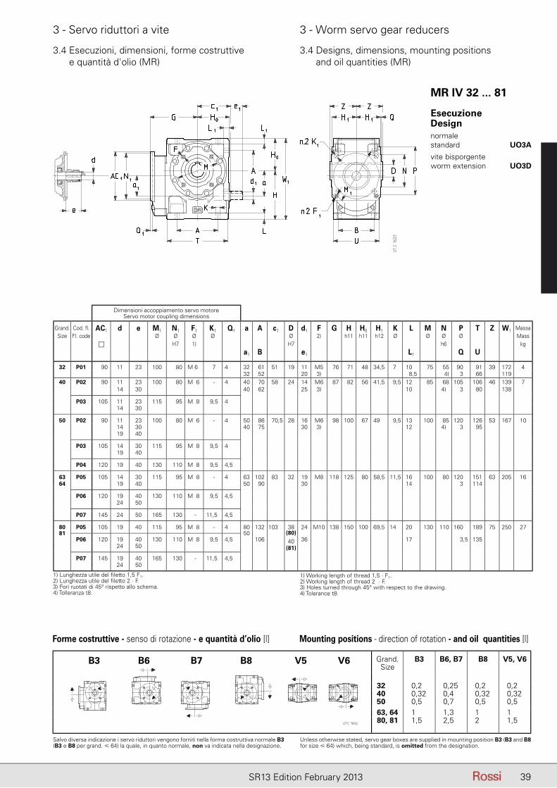
39SR13 Edition February 2013
3 - Servo riduttori a vite 3 - Worm servo gear reducers
3.4 Esecuzioni, dimensioni, forme costruttive e quantità d'olio (MR)
3.4 Designs, dimensions, mounting positions and oil quantities (MR)
Salvo diversa indicazione i servo riduttori vengono forniti nella forma costruttiva normale B3 (B3 e B8 per grand. � 64) la quale, in quanto normale, non va indicata nella designazione.
Unless otherwise stated, servo gear boxes are supplied in mounting position B3 (B3 and B8 for size � 64) which, being standard, is omitted from the designation.
Dimensioni accoppiamento servo motoreServo motor coupling dimensions
Grand. Cod. fl. AC1 d e M1 N1 F1 K1 Q1 a A c1 D d1 F G H H0 H1 K L M N P T Z W1 MassaSize Fl. code Ø Ø Ø Ø Ø 2) h11 h11 h12 Ø Ø Ø Ø Mass
H7 1) H7 h6 kga1 B e1 L1 Q U
32 P01 90 11 23 100 80 M 6 7 4 32 61 51 19 11 M5 76 71 48 34,5 7 10 75 55 90 91 39 172 432 52 20 3) 8,5 4) 3 66 119
40 P02 90 11 23 100 80 M06 - 4 40 70 58 24 14 M6 87 82 56 41,5 9,5 12 85 68 105 106 46 139 714 30 40 62 25 3) 10 4) 3 80 138
P03 105 11 23 115 95 M08 9,5 414 30
50 P02 90 11 23 100 80 M06 - 4 50 86 70,5 28 16 M6 98 100 67 49 9,5 13 100 85 120 126 53 167 1014 30 40 75 30 3) 12 4) 3 9519 40
P03 105 14 30 115 95 M08 9,5 419 40
P04 120 19 40 130 110 M08 9,5 4,5
63 P05 105 14 30 115 95 M08 - 4 63 102 83 32 19 M8 118 125 80 58,5 11,5 16 100 80 120 151 63 205 1664 19 40 50 90 30 14 3 114
P06 120 19 40 130 110 M08 9,5 4,524 50
P07 145 24 50 165 130 - 11,5 4,5
80 P05 105 19 40 115 95 M08 - 4 80 132 103 38 24 M10 138 150 100 69,5 14 20 130 110 160 189 75 250 2781 50
P06 120 19 40 130 110 M08 9,5 4,5 106(80)
36 17 3,5 13524 50
40
P07 145 19 40 165 130 - 11,5 4,5
(81)
24 50
Grand.Size
B3 B6, B7 B8 V5, V6
32 0,2 0,25 0,2 0,240 0,32 0,4 0,32 0,3250 0,5 0,7 0,5 0,563, 64 1 1,3 1 180, 81 1,5 2,5 2 1,5
Forme costruttive - senso di rotazione - e quantità d’olio [l] Mounting positions - direction of rotation - and oil quantities [l]
B3 B6 B7 B8 V5 V6
MR IV 32 ... 81
EsecuzioneDesignnormale standard UO3A
vite bisporgente worm extension UO3D
1) Lunghezza utile del filetto 1,5 F1.2) Lunghezza utile del filetto 2 · F.3) Fori ruotati di 45° rispetto allo schema.4) Tolleranza t8.
1) Working length of thread 1,5 · F1.2) Working length of thread 2 · F.3) Holes turned through 45° with respect to the drawing.4) Tolerance t8.
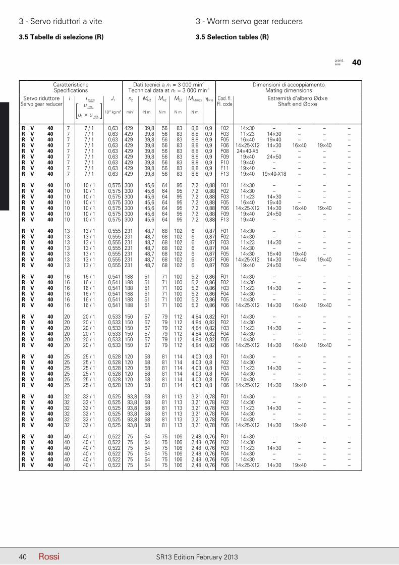
40 SR13 Edition February 2013
3 - Servo riduttori a vite 3 - Worm servo gear reducers
40 SR13 Edition February 2013
3.5 Tabelle di selezione (R) 3.5 Selection tables (R)
CaratteristicheSpecifications
Dati tecnici a n1 = 3 000 min-1
Technical data at n1 = 3 000 min-1Dimensioni di accoppiamento
Mating dimensionsServo riduttore
Servo gear reduceri iesatto - exact J1 n2 MN2 MA2 ME2 MA1max ηvite Cod. fl.
Fl. codeEstremità d’albero Ød×e
Shaft end Ød×e10-4 kg m2 min-1 N m N m N m N m
R V 40 7 7 / 1 0,63 429 39,8 56 83 8,8 0,9 F02 14×30 – – – –R V 40 7 7 / 1 0,63 429 39,8 56 83 8,8 0,9 F03 11×23 14×30 – – –R V 40 7 7 / 1 0,63 429 39,8 56 83 8,8 0,9 F05 16×40 19×40 – – –R V 40 7 7 / 1 0,63 429 39,8 56 83 8,8 0,9 F06 14×25-X12 14×30 16×40 19×40 –R V 40 7 7 / 1 0,63 429 39,8 56 83 8,8 0,9 F08 24×40-X5 – – – –R V 40 7 7 / 1 0,63 429 39,8 56 83 8,8 0,9 F09 19×40 24×50 – – –R V 40 7 7 / 1 0,63 429 39,8 56 83 8,8 0,9 F10 19×40 – – – –R V 40 7 7 / 1 0,63 429 39,8 56 83 8,8 0,9 F11 19×40 – – – –R V 40 7 7 / 1 0,63 429 39,8 56 83 8,8 0,9 F13 19×40 19×40-X18 – – –
R V 40 10 10 / 1 0,575 300 45,6 64 95 7,2 0,88 F01 14×30 – – – –R V 40 10 10 / 1 0,575 300 45,6 64 95 7,2 0,88 F02 14×30 – – – –R V 40 10 10 / 1 0,575 300 45,6 64 95 7,2 0,88 F03 11×23 14×30 – – –R V 40 10 10 / 1 0,575 300 45,6 64 95 7,2 0,88 F05 16×40 19×40 – – –R V 40 10 10 / 1 0,575 300 45,6 64 95 7,2 0,88 F06 14×25-X12 14×30 16×40 19×40 –R V 40 10 10 / 1 0,575 300 45,6 64 95 7,2 0,88 F09 19×40 24×50 – – –R V 40 10 10 / 1 0,575 300 45,6 64 95 7,2 0,88 F13 19×40 – – – –
R V 40 13 13 / 1 0,555 231 48,7 68 102 6 0,87 F01 14×30 – – – –R V 40 13 13 / 1 0,555 231 48,7 68 102 6 0,87 F02 14×30 – – – –R V 40 13 13 / 1 0,555 231 48,7 68 102 6 0,87 F03 11×23 14×30 – – –R V 40 13 13 / 1 0,555 231 48,7 68 102 6 0,87 F04 14×30 – – – –R V 40 13 13 / 1 0,555 231 48,7 68 102 6 0,87 F05 14×30 16×40 19×40 – –R V 40 13 13 / 1 0,555 231 48,7 68 102 6 0,87 F06 14×25-X12 14×30 16×40 19×40 –R V 40 13 13 / 1 0,555 231 48,7 68 102 6 0,87 F09 19×40 24×50 – – –
R V 40 16 16 / 1 0,541 188 51 71 100 5,2 0,86 F01 14×30 – – – –R V 40 16 16 / 1 0,541 188 51 71 100 5,2 0,86 F02 14×30 – – – –R V 40 16 16 / 1 0,541 188 51 71 100 5,2 0,86 F03 11×23 14×30 – – –R V 40 16 16 / 1 0,541 188 51 71 100 5,2 0,86 F04 14×30 – – – –R V 40 16 16 / 1 0,541 188 51 71 100 5,2 0,86 F05 14×30 – – – –R V 40 16 16 / 1 0,541 188 51 71 100 5,2 0,86 F06 14×25-X12 14×30 16×40 19×40 –
R V 40 20 20 / 1 0,533 150 57 79 112 4,84 0,82 F01 14×30 – – – –R V 40 20 20 / 1 0,533 150 57 79 112 4,84 0,82 F02 14×30 – – – –R V 40 20 20 / 1 0,533 150 57 79 112 4,84 0,82 F03 11×23 14×30 – – –R V 40 20 20 / 1 0,533 150 57 79 112 4,84 0,82 F04 14×30 – – – –R V 40 20 20 / 1 0,533 150 57 79 112 4,84 0,82 F05 14×30 – – – –R V 40 20 20 / 1 0,533 150 57 79 112 4,84 0,82 F06 14×25-X12 14×30 16×40 19×40 –
R V 40 25 25 / 1 0,528 120 58 81 114 4,03 0,8 F01 14×30 – – – –R V 40 25 25 / 1 0,528 120 58 81 114 4,03 0,8 F02 14×30 – – – –R V 40 25 25 / 1 0,528 120 58 81 114 4,03 0,8 F03 11×23 14×30 – – –R V 40 25 25 / 1 0,528 120 58 81 114 4,03 0,8 F04 14×30 – – – –R V 40 25 25 / 1 0,528 120 58 81 114 4,03 0,8 F05 14×30 – – – –R V 40 25 25 / 1 0,528 120 58 81 114 4,03 0,8 F06 14×25-X12 14×30 19×40 – –
R V 40 32 32 / 1 0,525 93,8 58 81 113 3,21 0,78 F01 14×30 – – – –R V 40 32 32 / 1 0,525 93,8 58 81 113 3,21 0,78 F02 14×30 – – – –R V 40 32 32 / 1 0,525 93,8 58 81 113 3,21 0,78 F03 11×23 14×30 – – –R V 40 32 32 / 1 0,525 93,8 58 81 113 3,21 0,78 F04 14×30 – – – –R V 40 32 32 / 1 0,525 93,8 58 81 113 3,21 0,78 F05 14×30 – – – –R V 40 32 32 / 1 0,525 93,8 58 81 113 3,21 0,78 F06 14×25-X12 14×30 19×40 – –
R V 40 40 40 / 1 0,522 75 54 75 106 2,48 0,76 F01 14×30 – – – –R V 40 40 40 / 1 0,522 75 54 75 106 2,48 0,76 F02 14×30 – – – –R V 40 40 40 / 1 0,522 75 54 75 106 2,48 0,76 F03 11×23 14×30 – – –R V 40 40 40 / 1 0,522 75 54 75 106 2,48 0,76 F04 14×30 – – – –R V 40 40 40 / 1 0,522 75 54 75 106 2,48 0,76 F05 14×30 – – – –R V 40 40 40 / 1 0,522 75 54 75 106 2,48 0,76 F06 14×25-X12 14×30 19×40 – –
grand. size 40
i esatto
u
u1 × u
viteworm
viteworm
[ ]i esatto
exact

41SR13 Edition February 2013
3 - Servo riduttori a vite 3 - Worm servo gear reducers
3.5 Tabelle di selezione (R) 3.5 Selection tables (R)
CaratteristicheSpecifications
Dati tecnici a n1 = 3 000 min-1
Technical data at n1 = 3 000 min-1Dimensioni di accoppiamento
Mating dimensionsServo riduttore
Servo gear reduceri iesatto - exact J1 n2 MN2 MA2 ME2 MA1max ηvite Cod. fl.
Fl. codeEstremità d’albero Ød×e
Shaft end Ød×e10-4 kg m2 min-1 N m N m N m N m
R V 40 50 50 / 1 0,521 60 52 73 103 1,98 0,73 F01 14×30 – – – –R V 40 50 50 / 1 0,521 60 52 73 103 1,98 0,73 F02 14×30 – – – –R V 40 50 50 / 1 0,521 60 52 73 103 1,98 0,73 F03 11×23 14×30 – – –R V 40 50 50 / 1 0,521 60 52 73 103 1,98 0,73 F04 14×30 – – – –R V 40 50 50 / 1 0,521 60 52 73 103 1,98 0,73 F05 14×30 – – – –R V 40 50 50 / 1 0,521 60 52 73 103 1,98 0,73 F06 14×30 19×40 – – –
R IV 40 49,9 78 / 25 - 16 / 1 0,148 60,1 76 96 131 2,43 0,81 F01 14×30 – – – –R IV 40 49,9 78 / 25 - 16 / 1 0,148 60,1 76 96 131 2,43 0,81 F03 11×23 14×30 – – –R IV 40 49,9 78 / 25 - 16 / 1 0,148 60,1 76 96 131 2,43 0,81 F04 14×30 – – – –R IV 40 49,9 78 / 25 - 16 / 1 0,148 60,1 76 96 131 2,43 0,81 F05 14×30 – – – –
R V 40 63 63 / 1 0,521 47,6 48,5 60 77 1,36 0,7 F01 14×30 – – – –R V 40 63 63 / 1 0,521 47,6 48,5 60 77 1,36 0,7 F02 14×30 – – – –R V 40 63 63 / 1 0,521 47,6 48,5 60 77 1,36 0,7 F03 11×23 14×30 – – –R V 40 63 63 / 1 0,521 47,6 48,5 60 77 1,36 0,7 F04 14×30 – – – –R V 40 63 63 / 1 0,521 47,6 48,5 60 77 1,36 0,7 F05 14×30 – – – –
R IV 40 62,4 78 / 25 - 20 / 1 0,147 48,1 82 104 144 2,25 0,76 F01 14×30 – – – –R IV 40 62,4 78 / 25 - 20 / 1 0,147 48,1 82 104 144 2,25 0,76 F03 11×23 14×30 – – –R IV 40 62,4 78 / 25 - 20 / 1 0,147 48,1 82 104 144 2,25 0,76 F05 14×30 – – – –
R IV 40 78 78 / 25 - 25 / 1 0,147 38,5 81 104 139 1,84 0,74 F03 11×23 14×30 – – –
R IV 40 99,8 78 / 25 - 32 / 1 0,146 30 79 101 138 1,45 0,71 F03 11×23 14×30 – – –
R IV 40 125 78 / 25 - 40 / 1 0,146 24 73 93 127 1,12 0,68 F03 11×23 – – – –
grand. size 40
i esatto
u
u1 × u
viteworm
viteworm
[ ]i esatto
exact
41SR13 Edition February 2013
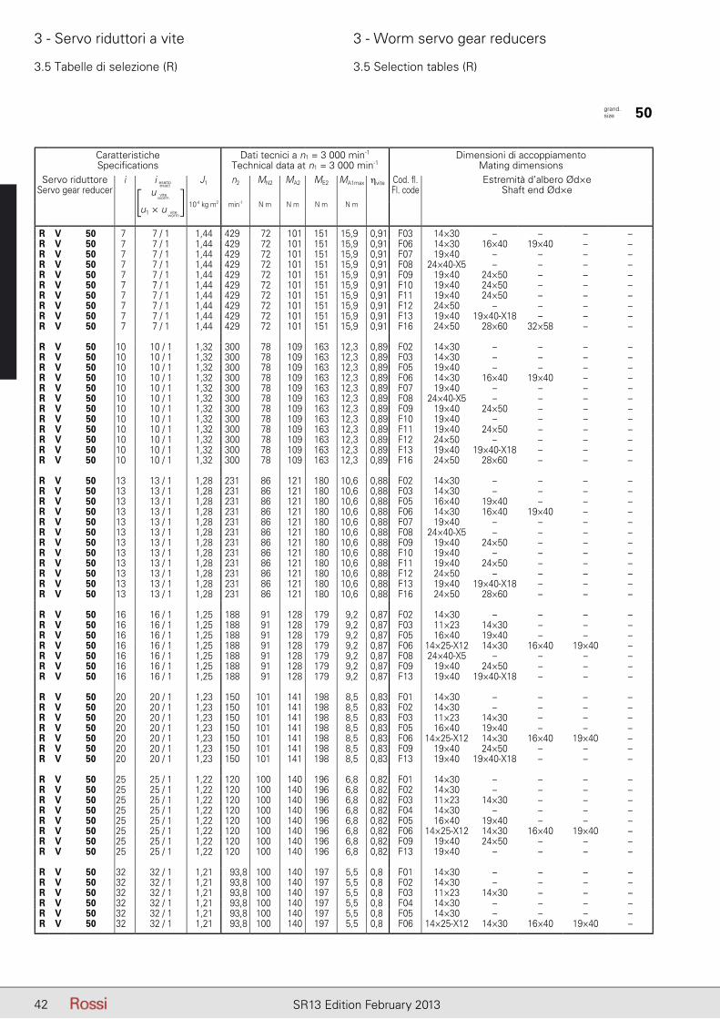
42 SR13 Edition February 2013
3 - Servo riduttori a vite 3 - Worm servo gear reducers
3.5 Tabelle di selezione (R) 3.5 Selection tables (R)
CaratteristicheSpecifications
Dati tecnici a n1 = 3 000 min-1
Technical data at n1 = 3 000 min-1Dimensioni di accoppiamento
Mating dimensionsServo riduttore
Servo gear reduceri iesatto - exact J1 n2 MN2 MA2 ME2 MA1max ηvite Cod. fl.
Fl. codeEstremità d’albero Ød×e
Shaft end Ød×e10-4 kg m2 min-1 N m N m N m N m
R V 50 7 7 / 1 1,44 429 72 101 151 15,9 0,91 F03 14×30 – – – –R V 50 7 7 / 1 1,44 429 72 101 151 15,9 0,91 F06 14×30 16×40 19×40 – –R V 50 7 7 / 1 1,44 429 72 101 151 15,9 0,91 F07 19×40 – – – –R V 50 7 7 / 1 1,44 429 72 101 151 15,9 0,91 F08 24×40-X5 – – – –R V 50 7 7 / 1 1,44 429 72 101 151 15,9 0,91 F09 19×40 24×50 – – –R V 50 7 7 / 1 1,44 429 72 101 151 15,9 0,91 F10 19×40 24×50 – – –R V 50 7 7 / 1 1,44 429 72 101 151 15,9 0,91 F11 19×40 24×50 – – –R V 50 7 7 / 1 1,44 429 72 101 151 15,9 0,91 F12 24×50 – – – –R V 50 7 7 / 1 1,44 429 72 101 151 15,9 0,91 F13 19×40 19×40-X18 – – –R V 50 7 7 / 1 1,44 429 72 101 151 15,9 0,91 F16 24×50 28×60 32×58 – –
R V 50 10 10 / 1 1,32 300 78 109 163 12,3 0,89 F02 14×30 – – – –R V 50 10 10 / 1 1,32 300 78 109 163 12,3 0,89 F03 14×30 – – – –R V 50 10 10 / 1 1,32 300 78 109 163 12,3 0,89 F05 19×40 – – – –R V 50 10 10 / 1 1,32 300 78 109 163 12,3 0,89 F06 14×30 16×40 19×40 – –R V 50 10 10 / 1 1,32 300 78 109 163 12,3 0,89 F07 19×40 – – – –R V 50 10 10 / 1 1,32 300 78 109 163 12,3 0,89 F08 24×40-X5 – – – –R V 50 10 10 / 1 1,32 300 78 109 163 12,3 0,89 F09 19×40 24×50 – – –R V 50 10 10 / 1 1,32 300 78 109 163 12,3 0,89 F10 19×40 – – – –R V 50 10 10 / 1 1,32 300 78 109 163 12,3 0,89 F11 19×40 24×50 – – –R V 50 10 10 / 1 1,32 300 78 109 163 12,3 0,89 F12 24×50 – – – –R V 50 10 10 / 1 1,32 300 78 109 163 12,3 0,89 F13 19×40 19×40-X18 – – –R V 50 10 10 / 1 1,32 300 78 109 163 12,3 0,89 F16 24×50 28×60 – – –
R V 50 13 13 / 1 1,28 231 86 121 180 10,6 0,88 F02 14×30 – – – –R V 50 13 13 / 1 1,28 231 86 121 180 10,6 0,88 F03 14×30 – – – –R V 50 13 13 / 1 1,28 231 86 121 180 10,6 0,88 F05 16×40 19×40 – – –R V 50 13 13 / 1 1,28 231 86 121 180 10,6 0,88 F06 14×30 16×40 19×40 – –R V 50 13 13 / 1 1,28 231 86 121 180 10,6 0,88 F07 19×40 – – – –R V 50 13 13 / 1 1,28 231 86 121 180 10,6 0,88 F08 24×40-X5 – – – –R V 50 13 13 / 1 1,28 231 86 121 180 10,6 0,88 F09 19×40 24×50 – – –R V 50 13 13 / 1 1,28 231 86 121 180 10,6 0,88 F10 19×40 – – – –R V 50 13 13 / 1 1,28 231 86 121 180 10,6 0,88 F11 19×40 24×50 – – –R V 50 13 13 / 1 1,28 231 86 121 180 10,6 0,88 F12 24×50 – – – –R V 50 13 13 / 1 1,28 231 86 121 180 10,6 0,88 F13 19×40 19×40-X18 – – –R V 50 13 13 / 1 1,28 231 86 121 180 10,6 0,88 F16 24×50 28×60 – – –
R V 50 16 16 / 1 1,25 188 91 128 179 9,2 0,87 F02 14×30 – – – –R V 50 16 16 / 1 1,25 188 91 128 179 9,2 0,87 F03 11×23 14×30 – – –R V 50 16 16 / 1 1,25 188 91 128 179 9,2 0,87 F05 16×40 19×40 – – –R V 50 16 16 / 1 1,25 188 91 128 179 9,2 0,87 F06 14×25-X12 14×30 16×40 19×40 –R V 50 16 16 / 1 1,25 188 91 128 179 9,2 0,87 F08 24×40-X5 – – – –R V 50 16 16 / 1 1,25 188 91 128 179 9,2 0,87 F09 19×40 24×50 – – –R V 50 16 16 / 1 1,25 188 91 128 179 9,2 0,87 F13 19×40 19×40-X18 – – –
R V 50 20 20 / 1 1,23 150 101 141 198 8,5 0,83 F01 14×30 – – – –R V 50 20 20 / 1 1,23 150 101 141 198 8,5 0,83 F02 14×30 – – – –R V 50 20 20 / 1 1,23 150 101 141 198 8,5 0,83 F03 11×23 14×30 – – –R V 50 20 20 / 1 1,23 150 101 141 198 8,5 0,83 F05 16×40 19×40 – – –R V 50 20 20 / 1 1,23 150 101 141 198 8,5 0,83 F06 14×25-X12 14×30 16×40 19×40 –R V 50 20 20 / 1 1,23 150 101 141 198 8,5 0,83 F09 19×40 24×50 – – –R V 50 20 20 / 1 1,23 150 101 141 198 8,5 0,83 F13 19×40 19×40-X18 – – –
R V 50 25 25 / 1 1,22 120 100 140 196 6,8 0,82 F01 14×30 – – – –R V 50 25 25 / 1 1,22 120 100 140 196 6,8 0,82 F02 14×30 – – – –R V 50 25 25 / 1 1,22 120 100 140 196 6,8 0,82 F03 11×23 14×30 – – –R V 50 25 25 / 1 1,22 120 100 140 196 6,8 0,82 F04 14×30 – – – –R V 50 25 25 / 1 1,22 120 100 140 196 6,8 0,82 F05 16×40 19×40 – – –R V 50 25 25 / 1 1,22 120 100 140 196 6,8 0,82 F06 14×25-X12 14×30 16×40 19×40 –R V 50 25 25 / 1 1,22 120 100 140 196 6,8 0,82 F09 19×40 24×50 – – –R V 50 25 25 / 1 1,22 120 100 140 196 6,8 0,82 F13 19×40 – – – –
R V 50 32 32 / 1 1,21 93,8 100 140 197 5,5 0,8 F01 14×30 – – – –R V 50 32 32 / 1 1,21 93,8 100 140 197 5,5 0,8 F02 14×30 – – – –R V 50 32 32 / 1 1,21 93,8 100 140 197 5,5 0,8 F03 11×23 14×30 – – –R V 50 32 32 / 1 1,21 93,8 100 140 197 5,5 0,8 F04 14×30 – – – –R V 50 32 32 / 1 1,21 93,8 100 140 197 5,5 0,8 F05 14×30 – – – –R V 50 32 32 / 1 1,21 93,8 100 140 197 5,5 0,8 F06 14×25-X12 14×30 16×40 19×40 –
grand. size 50
i esatto
u
u1 × u
viteworm
viteworm
[ ]i esatto
exact
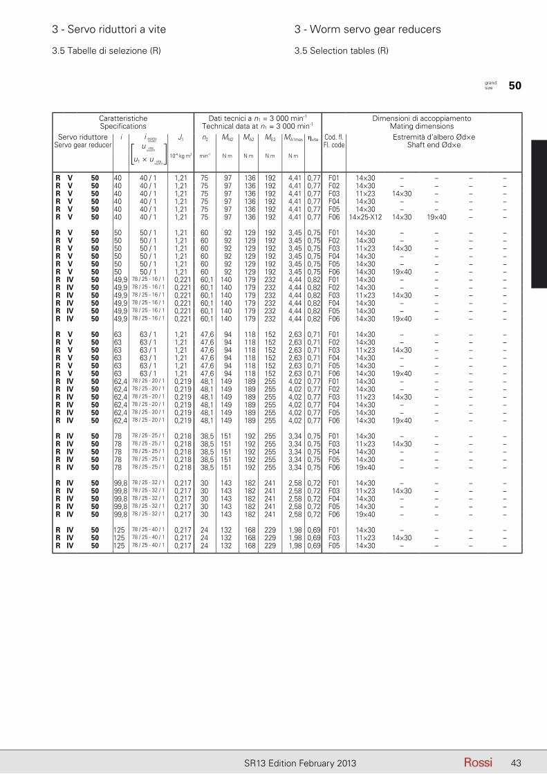
43SR13 Edition February 2013
3 - Servo riduttori a vite 3 - Worm servo gear reducers
3.5 Tabelle di selezione (R) 3.5 Selection tables (R)
CaratteristicheSpecifications
Dati tecnici a n1 = 3 000 min-1
Technical data at n1 = 3 000 min-1Dimensioni di accoppiamento
Mating dimensionsServo riduttore
Servo gear reduceri iesatto - exact J1 n2 MN2 MA2 ME2 MA1max ηvite Cod. fl.
Fl. codeEstremità d’albero Ød×e
Shaft end Ød×e10-4 kg m2 min-1 N m N m N m N m
R V 50 40 40 / 1 1,21 75 97 136 192 4,41 0,77 F01 14×30 – – – –R V 50 40 40 / 1 1,21 75 97 136 192 4,41 0,77 F02 14×30 – – – –R V 50 40 40 / 1 1,21 75 97 136 192 4,41 0,77 F03 11×23 14×30 – – –R V 50 40 40 / 1 1,21 75 97 136 192 4,41 0,77 F04 14×30 – – – –R V 50 40 40 / 1 1,21 75 97 136 192 4,41 0,77 F05 14×30 – – – –R V 50 40 40 / 1 1,21 75 97 136 192 4,41 0,77 F06 14×25-X12 14×30 19×40 – –
R V 50 50 50 / 1 1,21 60 92 129 192 3,45 0,75 F01 14×30 – – – –R V 50 50 50 / 1 1,21 60 92 129 192 3,45 0,75 F02 14×30 – – – –R V 50 50 50 / 1 1,21 60 92 129 192 3,45 0,75 F03 11×23 14×30 – – –R V 50 50 50 / 1 1,21 60 92 129 192 3,45 0,75 F04 14×30 – – – –R V 50 50 50 / 1 1,21 60 92 129 192 3,45 0,75 F05 14×30 – – – –R V 50 50 50 / 1 1,21 60 92 129 192 3,45 0,75 F06 14×30 19×40 – – –R IV 50 49,9 78 / 25 - 16 / 1 0,221 60,1 140 179 232 4,44 0,82 F01 14×30 – – – –R IV 50 49,9 78 / 25 - 16 / 1 0,221 60,1 140 179 232 4,44 0,82 F02 14×30 – – – –R IV 50 49,9 78 / 25 - 16 / 1 0,221 60,1 140 179 232 4,44 0,82 F03 11×23 14×30 – – –R IV 50 49,9 78 / 25 - 16 / 1 0,221 60,1 140 179 232 4,44 0,82 F04 14×30 – – – –R IV 50 49,9 78 / 25 - 16 / 1 0,221 60,1 140 179 232 4,44 0,82 F05 14×30 – – – –R IV 50 49,9 78 / 25 - 16 / 1 0,221 60,1 140 179 232 4,44 0,82 F06 14×30 19×40 – – –
R V 50 63 63 / 1 1,21 47,6 94 118 152 2,63 0,71 F01 14×30 – – – –R V 50 63 63 / 1 1,21 47,6 94 118 152 2,63 0,71 F02 14×30 – – – –R V 50 63 63 / 1 1,21 47,6 94 118 152 2,63 0,71 F03 11×23 14×30 – – –R V 50 63 63 / 1 1,21 47,6 94 118 152 2,63 0,71 F04 14×30 – – – –R V 50 63 63 / 1 1,21 47,6 94 118 152 2,63 0,71 F05 14×30 – – – –R V 50 63 63 / 1 1,21 47,6 94 118 152 2,63 0,71 F06 14×30 19×40 – – –R IV 50 62,4 78 / 25 - 20 / 1 0,219 48,1 149 189 255 4,02 0,77 F01 14×30 – – – –R IV 50 62,4 78 / 25 - 20 / 1 0,219 48,1 149 189 255 4,02 0,77 F02 14×30 – – – –R IV 50 62,4 78 / 25 - 20 / 1 0,219 48,1 149 189 255 4,02 0,77 F03 11×23 14×30 – – –R IV 50 62,4 78 / 25 - 20 / 1 0,219 48,1 149 189 255 4,02 0,77 F04 14×30 – – – –R IV 50 62,4 78 / 25 - 20 / 1 0,219 48,1 149 189 255 4,02 0,77 F05 14×30 – – – –R IV 50 62,4 78 / 25 - 20 / 1 0,219 48,1 149 189 255 4,02 0,77 F06 14×30 19×40 – – –
R IV 50 78 78 / 25 - 25 / 1 0,218 38,5 151 192 255 3,34 0,75 F01 14×30 – – – –R IV 50 78 78 / 25 - 25 / 1 0,218 38,5 151 192 255 3,34 0,75 F03 11×23 14×30 – – –R IV 50 78 78 / 25 - 25 / 1 0,218 38,5 151 192 255 3,34 0,75 F04 14×30 – – – –R IV 50 78 78 / 25 - 25 / 1 0,218 38,5 151 192 255 3,34 0,75 F05 14×30 – – – –R IV 50 78 78 / 25 - 25 / 1 0,218 38,5 151 192 255 3,34 0,75 F06 19×40 – – – –
R IV 50 99,8 78 / 25 - 32 / 1 0,217 30 143 182 241 2,58 0,72 F01 14×30 – – – –R IV 50 99,8 78 / 25 - 32 / 1 0,217 30 143 182 241 2,58 0,72 F03 11×23 14×30 – – –R IV 50 99,8 78 / 25 - 32 / 1 0,217 30 143 182 241 2,58 0,72 F04 14×30 – – – –R IV 50 99,8 78 / 25 - 32 / 1 0,217 30 143 182 241 2,58 0,72 F05 14×30 – – – –R IV 50 99,8 78 / 25 - 32 / 1 0,217 30 143 182 241 2,58 0,72 F06 19×40 – – – –
R IV 50 125 78 / 25 - 40 / 1 0,217 24 132 168 229 1,98 0,69 F01 14×30 – – – –R IV 50 125 78 / 25 - 40 / 1 0,217 24 132 168 229 1,98 0,69 F03 11×23 14×30 – – –R IV 50 125 78 / 25 - 40 / 1 0,217 24 132 168 229 1,98 0,69 F05 14×30 – – – –
grand. size 50
i esatto
u
u1 × u
viteworm
viteworm
[ ]i esatto
exact

44 SR13 Edition February 2013
3 - Servo riduttori a vite 3 - Worm servo gear reducers
3.5 Tabelle di selezione (R) 3.5 Selection tables (R)
CaratteristicheSpecifications
Dati tecnici a n1 = 3 000 min-1
Technical data at n1 = 3 000 min-1Dimensioni di accoppiamento
Mating dimensionsServo riduttore
Servo gear reduceri iesatto - exact J1 n2 MN2 MA2 ME2 MA1max ηvite Cod. fl.
Fl. codeEstremità d’albero Ød×e
Shaft end Ød×e10-4 kg m2 min-1 N m N m N m N m
R V 63 7 7 / 1 2,95 429 118 165 246 25,7 0,92 F06 14×30 19×40 – – –R V 63 7 7 / 1 2,95 429 118 165 246 25,7 0,92 F08 24×40-X5 – – – –R V 63 7 7 / 1 2,95 429 118 165 246 25,7 0,92 F09 19×40 24×50 – – –R V 63 7 7 / 1 2,95 429 118 165 246 25,7 0,92 F10 19×40 24×50 – – –R V 63 7 7 / 1 2,95 429 118 165 246 25,7 0,92 F11 19×40 24×50 – – –R V 63 7 7 / 1 2,95 429 118 165 246 25,7 0,92 F12 24×50 – – – –R V 63 7 7 / 1 2,95 429 118 165 246 25,7 0,92 F13 19×40-X18 22×40-X18 – – –R V 63 7 7 / 1 2,95 429 118 165 246 25,7 0,92 F16 24×50 28×60 32×58 – –
R V 63 10 10 / 1 2,64 300 138 193 288 21,4 0,9 F06 14×30 16×40 19×40 – –R V 63 10 10 / 1 2,64 300 138 193 288 21,4 0,9 F08 24×40-X5 – – – –R V 63 10 10 / 1 2,64 300 138 193 288 21,4 0,9 F09 19×40 24×50 – – –R V 63 10 10 / 1 2,64 300 138 193 288 21,4 0,9 F10 19×40 – – – –R V 63 10 10 / 1 2,64 300 138 193 288 21,4 0,9 F11 19×40 24×50 – – –R V 63 10 10 / 1 2,64 300 138 193 288 21,4 0,9 F12 24×50 – – – –R V 63 10 10 / 1 2,64 300 138 193 288 21,4 0,9 F13 19×40 19×40-X18 – – –R V 63 10 10 / 1 2,64 300 138 193 288 21,4 0,9 F16 24×50 28×60 32×58 – –
R V 63 13 13 / 1 2,52 231 142 199 296 17,2 0,89 F03 14×30 – – – –R V 63 13 13 / 1 2,52 231 142 199 296 17,2 0,89 F06 14×30 16×40 19×40 – –R V 63 13 13 / 1 2,52 231 142 199 296 17,2 0,89 F07 19×40 – – – –R V 63 13 13 / 1 2,52 231 142 199 296 17,2 0,89 F08 24×40-X5 – – – –R V 63 13 13 / 1 2,52 231 142 199 296 17,2 0,89 F09 19×40 24×50 – – –R V 63 13 13 / 1 2,52 231 142 199 296 17,2 0,89 F10 19×40 – – – –R V 63 13 13 / 1 2,52 231 142 199 296 17,2 0,89 F11 19×40 24×50 – – –R V 63 13 13 / 1 2,52 231 142 199 296 17,2 0,89 F12 24×50 – – – –R V 63 13 13 / 1 2,52 231 142 199 296 17,2 0,89 F13 19×40 19×40-X18 – – –R V 63 13 13 / 1 2,52 231 142 199 296 17,2 0,89 F16 24×50 28×60 32×58 – –
R V 63 16 16 / 1 2,44 188 151 211 296 15 0,88 F02 14×30 – – – –R V 63 16 16 / 1 2,44 188 151 211 296 15 0,88 F03 14×30 – – – –R V 63 16 16 / 1 2,44 188 151 211 296 15 0,88 F05 19×40 – – – –R V 63 16 16 / 1 2,44 188 151 211 296 15 0,88 F06 14×30 16×40 19×40 – –R V 63 16 16 / 1 2,44 188 151 211 296 15 0,88 F07 19×40 – – – –R V 63 16 16 / 1 2,44 188 151 211 296 15 0,88 F08 24×40-X5 – – – –R V 63 16 16 / 1 2,44 188 151 211 296 15 0,88 F09 19×40 24×50 – – –R V 63 16 16 / 1 2,44 188 151 211 296 15 0,88 F10 19×40 – – – –R V 63 16 16 / 1 2,44 188 151 211 296 15 0,88 F11 19×40 24×50 – – –R V 63 16 16 / 1 2,44 188 151 211 296 15 0,88 F12 24×50 – – – –R V 63 16 16 / 1 2,44 188 151 211 296 15 0,88 F13 19×40 19×40-X18 – – –R V 63 16 16 / 1 2,44 188 151 211 296 15 0,88 F16 24×50 28×60 32×58 – –
R V 63 20 20 / 1 2,38 150 153 214 302 12,3 0,87 F02 14×30 – – – –R V 63 20 20 / 1 2,38 150 153 214 302 12,3 0,87 F03 14×30 – – – –R V 63 20 20 / 1 2,38 150 153 214 302 12,3 0,87 F05 16×40 19×40 – – –R V 63 20 20 / 1 2,38 150 153 214 302 12,3 0,87 F06 14×30 16×40 19×40 – –R V 63 20 20 / 1 2,38 150 153 214 302 12,3 0,87 F07 19×40 – – – –R V 63 20 20 / 1 2,38 150 153 214 302 12,3 0,87 F08 24×40-X5 – – – –R V 63 20 20 / 1 2,38 150 153 214 302 12,3 0,87 F09 19×40 24×50 – – –R V 63 20 20 / 1 2,38 150 153 214 302 12,3 0,87 F10 19×40 – – – –R V 63 20 20 / 1 2,38 150 153 214 302 12,3 0,87 F11 19×40 24×50 – – –R V 63 20 20 / 1 2,38 150 153 214 302 12,3 0,87 F12 24×50 – – – –R V 63 20 20 / 1 2,38 150 153 214 302 12,3 0,87 F13 19×40 19×40-X18 – – –R V 63 20 20 / 1 2,38 150 153 214 302 12,3 0,87 F16 24×50 28×60 – – –
R V 63 25 25 / 1 2,37 120 171 239 337 11,5 0,83 F02 14×30 – – – –R V 63 25 25 / 1 2,37 120 171 239 337 11,5 0,83 F03 11×23 14×30 – – –R V 63 25 25 / 1 2,37 120 171 239 337 11,5 0,83 F05 16×40 19×40 – – –R V 63 25 25 / 1 2,37 120 171 239 337 11,5 0,83 F06 14×30 16×40 19×40 – –R V 63 25 25 / 1 2,37 120 171 239 337 11,5 0,83 F08 24×40-X5 – – – –R V 63 25 25 / 1 2,37 120 171 239 337 11,5 0,83 F09 19×40 24×50 – – –R V 63 25 25 / 1 2,37 120 171 239 337 11,5 0,83 F10 19×40 – – – –R V 63 25 25 / 1 2,37 120 171 239 337 11,5 0,83 F11 19×40 24×50 – – –R V 63 25 25 / 1 2,37 120 171 239 337 11,5 0,83 F12 24×50 – – – –R V 63 25 25 / 1 2,37 120 171 239 337 11,5 0,83 F13 19×40 19×40-X18 – – –
R V 63 32 32 / 1 2,35 93,8 168 235 331 9 0,81 F01 14×30 – – – –R V 63 32 32 / 1 2,35 93,8 168 235 331 9 0,81 F02 14×30 – – – –R V 63 32 32 / 1 2,35 93,8 168 235 331 9 0,81 F03 11×23 14×30 – – –R V 63 32 32 / 1 2,35 93,8 168 235 331 9 0,81 F05 16×40 19×40 – – –R V 63 32 32 / 1 2,35 93,8 168 235 331 9 0,81 F06 14×25-X12 14×30 16×40 19×40 –
grand. size 63
i esatto
u
u1 × u
viteworm
viteworm
[ ]i esatto
exact
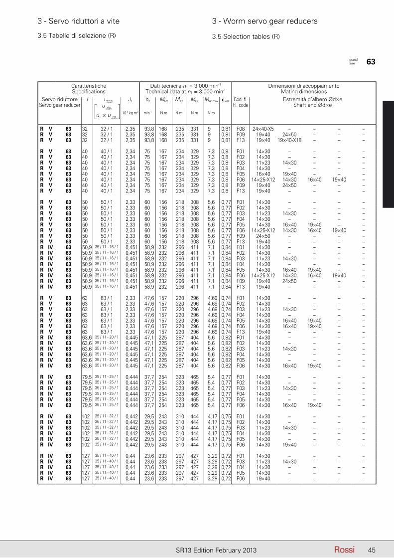
45SR13 Edition February 2013
3 - Servo riduttori a vite 3 - Worm servo gear reducers
3.5 Tabelle di selezione (R) 3.5 Selection tables (R)
CaratteristicheSpecifications
Dati tecnici a n1 = 3 000 min-1
Technical data at n1 = 3 000 min-1Dimensioni di accoppiamento
Mating dimensionsServo riduttore
Servo gear reduceri iesatto - exact J1 n2 MN2 MA2 ME2 MA1max ηvite Cod. fl.
Fl. codeEstremità d’albero Ød×e
Shaft end Ød×e10-4 kg m2 min-1 N m N m N m N m
R V 63 32 32 / 1 2,35 93,8 168 235 331 9 0,81 F08 24×40-X5 – – – –R V 63 32 32 / 1 2,35 93,8 168 235 331 9 0,81 F09 19×40 24×50 – – –R V 63 32 32 / 1 2,35 93,8 168 235 331 9 0,81 F13 19×40 19×40-X18 – – –
R V 63 40 40 / 1 2,34 75 167 234 329 7,3 0,8 F01 14×30 – – – –R V 63 40 40 / 1 2,34 75 167 234 329 7,3 0,8 F02 14×30 – – – –R V 63 40 40 / 1 2,34 75 167 234 329 7,3 0,8 F03 11×23 14×30 – – –R V 63 40 40 / 1 2,34 75 167 234 329 7,3 0,8 F04 14×30 – – – –R V 63 40 40 / 1 2,34 75 167 234 329 7,3 0,8 F05 16×40 19×40 – – –R V 63 40 40 / 1 2,34 75 167 234 329 7,3 0,8 F06 14×25-X12 14×30 16×40 19×40 –R V 63 40 40 / 1 2,34 75 167 234 329 7,3 0,8 F09 19×40 24×50 – – –R V 63 40 40 / 1 2,34 75 167 234 329 7,3 0,8 F13 19×40 – – – –
R V 63 50 50 / 1 2,33 60 156 218 308 5,6 0,77 F01 14×30 – – – –R V 63 50 50 / 1 2,33 60 156 218 308 5,6 0,77 F02 14×30 – – – –R V 63 50 50 / 1 2,33 60 156 218 308 5,6 0,77 F03 11×23 14×30 – – –R V 63 50 50 / 1 2,33 60 156 218 308 5,6 0,77 F04 14×30 – – – –R V 63 50 50 / 1 2,33 60 156 218 308 5,6 0,77 F05 14×30 16×40 19×40 – –R V 63 50 50 / 1 2,33 60 156 218 308 5,6 0,77 F06 14×25-X12 14×30 16×40 19×40 –R V 63 50 50 / 1 2,33 60 156 218 308 5,6 0,77 F09 24×50 – – – –R V 63 50 50 / 1 2,33 60 156 218 308 5,6 0,77 F13 19×40 – – – –R IV 63 50,9 35 / 11 - 16 / 1 0,451 58,9 232 296 411 7,1 0,84 F01 14×30 – – – –R IV 63 50,9 35 / 11 - 16 / 1 0,451 58,9 232 296 411 7,1 0,84 F02 14×30 – – – –R IV 63 50,9 35 / 11 - 16 / 1 0,451 58,9 232 296 411 7,1 0,84 F03 11×23 14×30 – – –R IV 63 50,9 35 / 11 - 16 / 1 0,451 58,9 232 296 411 7,1 0,84 F04 14×30 – – – –R IV 63 50,9 35 / 11 - 16 / 1 0,451 58,9 232 296 411 7,1 0,84 F05 14×30 16×40 19×40 – –R IV 63 50,9 35 / 11 - 16 / 1 0,451 58,9 232 296 411 7,1 0,84 F06 14×25-X12 14×30 16×40 19×40 –R IV 63 50,9 35 / 11 - 16 / 1 0,451 58,9 232 296 411 7,1 0,84 F09 19×40 24×50 – – –R IV 63 50,9 35 / 11 - 16 / 1 0,451 58,9 232 296 411 7,1 0,84 F13 19×40 – – – –
R V 63 63 63 / 1 2,33 47,6 157 220 296 4,69 0,74 F01 14×30 – – – –R V 63 63 63 / 1 2,33 47,6 157 220 296 4,69 0,74 F02 14×30 – – – –R V 63 63 63 / 1 2,33 47,6 157 220 296 4,69 0,74 F03 11×23 14×30 – – –R V 63 63 63 / 1 2,33 47,6 157 220 296 4,69 0,74 F04 14×30 – – – –R V 63 63 63 / 1 2,33 47,6 157 220 296 4,69 0,74 F05 14×30 16×40 19×40 – –R V 63 63 63 / 1 2,33 47,6 157 220 296 4,69 0,74 F06 14×30 16×40 19×40 – –R V 63 63 63 / 1 2,33 47,6 157 220 296 4,69 0,74 F13 19×40 – – – –R IV 63 63,6 35 / 11 - 20 / 1 0,445 47,1 225 287 404 5,6 0,82 F01 14×30 – – – –R IV 63 63,6 35 / 11 - 20 / 1 0,445 47,1 225 287 404 5,6 0,82 F02 14×30 – – – –R IV 63 63,6 35 / 11 - 20 / 1 0,445 47,1 225 287 404 5,6 0,82 F03 11×23 14×30 – – –R IV 63 63,6 35 / 11 - 20 / 1 0,445 47,1 225 287 404 5,6 0,82 F04 14×30 – – – –R IV 63 63,6 35 / 11 - 20 / 1 0,445 47,1 225 287 404 5,6 0,82 F05 14×30 – – – –R IV 63 63,6 35 / 11 - 20 / 1 0,445 47,1 225 287 404 5,6 0,82 F06 14×30 16×40 19×40 – –
R IV 63 79,5 35 / 11 - 25 / 1 0,444 37,7 254 323 465 5,4 0,77 F01 14×30 – – – –R IV 63 79,5 35 / 11 - 25 / 1 0,444 37,7 254 323 465 5,4 0,77 F02 14×30 – – – –R IV 63 79,5 35 / 11 - 25 / 1 0,444 37,7 254 323 465 5,4 0,77 F03 11×23 14×30 – – –R IV 63 79,5 35 / 11 - 25 / 1 0,444 37,7 254 323 465 5,4 0,77 F04 14×30 – – – –R IV 63 79,5 35 / 11 - 25 / 1 0,444 37,7 254 323 465 5,4 0,77 F05 14×30 – – – –R IV 63 79,5 35 / 11 - 25 / 1 0,444 37,7 254 323 465 5,4 0,77 F06 14×30 16×40 19×40 – –
R IV 63 102 35 / 11 - 32 / 1 0,442 29,5 243 310 444 4,17 0,75 F01 14×30 – – – –R IV 63 102 35 / 11 - 32 / 1 0,442 29,5 243 310 444 4,17 0,75 F02 14×30 – – – –R IV 63 102 35 / 11 - 32 / 1 0,442 29,5 243 310 444 4,17 0,75 F03 11×23 14×30 – – –R IV 63 102 35 / 11 - 32 / 1 0,442 29,5 243 310 444 4,17 0,75 F04 14×30 – – – –R IV 63 102 35 / 11 - 32 / 1 0,442 29,5 243 310 444 4,17 0,75 F05 14×30 – – – –R IV 63 102 35 / 11 - 32 / 1 0,442 29,5 243 310 444 4,17 0,75 F06 14×30 19×40 – – –
R IV 63 127 35 / 11 - 40 / 1 0,44 23,6 233 297 427 3,29 0,72 F01 14×30 – – – –R IV 63 127 35 / 11 - 40 / 1 0,44 23,6 233 297 427 3,29 0,72 F03 11×23 14×30 – – –R IV 63 127 35 / 11 - 40 / 1 0,44 23,6 233 297 427 3,29 0,72 F04 14×30 – – – –R IV 63 127 35 / 11 - 40 / 1 0,44 23,6 233 297 427 3,29 0,72 F05 14×30 – – – –R IV 63 127 35 / 11 - 40 / 1 0,44 23,6 233 297 427 3,29 0,72 F06 19×40 – – – –
grand. size 63
i esatto
u
u1 × u
viteworm
viteworm
[ ]i esatto
exact

46 SR13 Edition February 2013
3 - Servo riduttori a vite 3 - Worm servo gear reducers
3.5 Tabelle di selezione (R) 3.5 Selection tables (R)
CaratteristicheSpecifications
Dati tecnici a n1 = 3 000 min-1
Technical data at n1 = 3 000 min-1Dimensioni di accoppiamento
Mating dimensionsServo riduttore
Servo gear reduceri iesatto - exact J1 n2 MN2 MA2 ME2 MA1max ηvite Cod. fl.
Fl. codeEstremità d’albero Ød×e
Shaft end Ød×e10-4 kg m2 min-1 N m N m N m N m
R V 64 7 7 / 1 2,95 429 141 197 268 30,8 0,92 F06 14×30 19×40 – – –R V 64 7 7 / 1 2,95 429 141 197 268 30,8 0,92 F08 24×40-X5 – – – –R V 64 7 7 / 1 2,95 429 141 197 268 30,8 0,92 F09 19×40 24×50 – – –R V 64 7 7 / 1 2,95 429 141 197 268 30,8 0,92 F10 19×40 24×50 – – –R V 64 7 7 / 1 2,95 429 141 197 268 30,8 0,92 F11 19×40 24×50 – – –R V 64 7 7 / 1 2,95 429 141 197 268 30,8 0,92 F12 24×50 – – – –R V 64 7 7 / 1 2,95 429 141 197 268 30,8 0,92 F13 22×40-X18 28×55-X8 – – –R V 64 7 7 / 1 2,95 429 141 197 268 30,8 0,92 F14 24×50 – – – –R V 64 7 7 / 1 2,95 429 141 197 268 30,8 0,92 F16 24×50 28×60 32×58 – –
R V 64 10 10 / 1 2,64 300 164 230 313 25,4 0,9 F06 14×30 19×40 – – –R V 64 10 10 / 1 2,64 300 164 230 313 25,4 0,9 F08 24×40-X5 – – – –R V 64 10 10 / 1 2,64 300 164 230 313 25,4 0,9 F09 19×40 24×50 – – –R V 64 10 10 / 1 2,64 300 164 230 313 25,4 0,9 F10 19×40 24×50 – – –R V 64 10 10 / 1 2,64 300 164 230 313 25,4 0,9 F11 19×40 24×50 – – –R V 64 10 10 / 1 2,64 300 164 230 313 25,4 0,9 F12 24×50 – – – –R V 64 10 10 / 1 2,64 300 164 230 313 25,4 0,9 F13 19×40-X18 22×40-X18 – – –R V 64 10 10 / 1 2,64 300 164 230 313 25,4 0,9 F16 24×50 28×60 32×58 – –
R V 64 13 13 / 1 2,52 231 169 237 322 20,5 0,89 F06 14×30 16×40 19×40 – –R V 64 13 13 / 1 2,52 231 169 237 322 20,5 0,89 F08 24×40-X5 – – – –R V 64 13 13 / 1 2,52 231 169 237 322 20,5 0,89 F09 19×40 24×50 – – –R V 64 13 13 / 1 2,52 231 169 237 322 20,5 0,89 F10 19×40 – – – –R V 64 13 13 / 1 2,52 231 169 237 322 20,5 0,89 F11 19×40 24×50 – – –R V 64 13 13 / 1 2,52 231 169 237 322 20,5 0,89 F12 24×50 – – – –R V 64 13 13 / 1 2,52 231 169 237 322 20,5 0,89 F13 19×40 19×40-X18 22×40-X18 – –R V 64 13 13 / 1 2,52 231 169 237 322 20,5 0,89 F16 24×50 28×60 32×58 – –
R V 64 16 16 / 1 2,44 188 179 251 322 17,8 0,88 F03 14×30 – – – –R V 64 16 16 / 1 2,44 188 179 251 322 17,8 0,88 F06 14×30 16×40 19×40 – –R V 64 16 16 / 1 2,44 188 179 251 322 17,8 0,88 F07 19×40 – – – –R V 64 16 16 / 1 2,44 188 179 251 322 17,8 0,88 F08 24×40-X5 – – – –R V 64 16 16 / 1 2,44 188 179 251 322 17,8 0,88 F09 19×40 24×50 – – –R V 64 16 16 / 1 2,44 188 179 251 322 17,8 0,88 F10 19×40 – – – –R V 64 16 16 / 1 2,44 188 179 251 322 17,8 0,88 F11 19×40 24×50 – – –R V 64 16 16 / 1 2,44 188 179 251 322 17,8 0,88 F12 24×50 – – – –R V 64 16 16 / 1 2,44 188 179 251 322 17,8 0,88 F13 19×40 19×40-X18 – – –R V 64 16 16 / 1 2,44 188 179 251 322 17,8 0,88 F16 24×50 28×60 32×58 – –
R V 64 20 20 / 1 2,38 150 183 256 328 14,7 0,87 F02 14×30 – – – –R V 64 20 20 / 1 2,38 150 183 256 328 14,7 0,87 F03 14×30 – – – –R V 64 20 20 / 1 2,38 150 183 256 328 14,7 0,87 F05 19×40 – – – –R V 64 20 20 / 1 2,38 150 183 256 328 14,7 0,87 F06 14×30 16×40 19×40 – –R V 64 20 20 / 1 2,38 150 183 256 328 14,7 0,87 F07 19×40 – – – –R V 64 20 20 / 1 2,38 150 183 256 328 14,7 0,87 F08 24×40-X5 – – – –R V 64 20 20 / 1 2,38 150 183 256 328 14,7 0,87 F09 19×40 24×50 – – –R V 64 20 20 / 1 2,38 150 183 256 328 14,7 0,87 F10 19×40 – – – –R V 64 20 20 / 1 2,38 150 183 256 328 14,7 0,87 F11 19×40 24×50 – – –R V 64 20 20 / 1 2,38 150 183 256 328 14,7 0,87 F12 24×50 – – – –R V 64 20 20 / 1 2,38 150 183 256 328 14,7 0,87 F13 19×40 19×40-X18 – – –R V 64 20 20 / 1 2,38 150 183 256 328 14,7 0,87 F16 24×50 28×60 32×58 – –
R V 64 25 25 / 1 2,37 120 204 286 366 13,7 0,83 F02 14×30 – – – –R V 64 25 25 / 1 2,37 120 204 286 366 13,7 0,83 F03 14×30 – – – –R V 64 25 25 / 1 2,37 120 204 286 366 13,7 0,83 F05 19×40 – – – –R V 64 25 25 / 1 2,37 120 204 286 366 13,7 0,83 F06 14×30 16×40 19×40 – –R V 64 25 25 / 1 2,37 120 204 286 366 13,7 0,83 F07 19×40 – – – –R V 64 25 25 / 1 2,37 120 204 286 366 13,7 0,83 F08 24×40-X5 – – – –R V 64 25 25 / 1 2,37 120 204 286 366 13,7 0,83 F09 19×40 24×50 – – –R V 64 25 25 / 1 2,37 120 204 286 366 13,7 0,83 F10 19×40 – – – –R V 64 25 25 / 1 2,37 120 204 286 366 13,7 0,83 F11 19×40 24×50 – – –R V 64 25 25 / 1 2,37 120 204 286 366 13,7 0,83 F12 24×50 – – – –R V 64 25 25 / 1 2,37 120 204 286 366 13,7 0,83 F13 19×40 19×40-X18 – – –R V 64 25 25 / 1 2,37 120 204 286 366 13,7 0,83 F16 24×50 28×60 32×58 – –
grand. size 64
i esatto
u
u1 × u
viteworm
viteworm
[ ]i esatto
exact
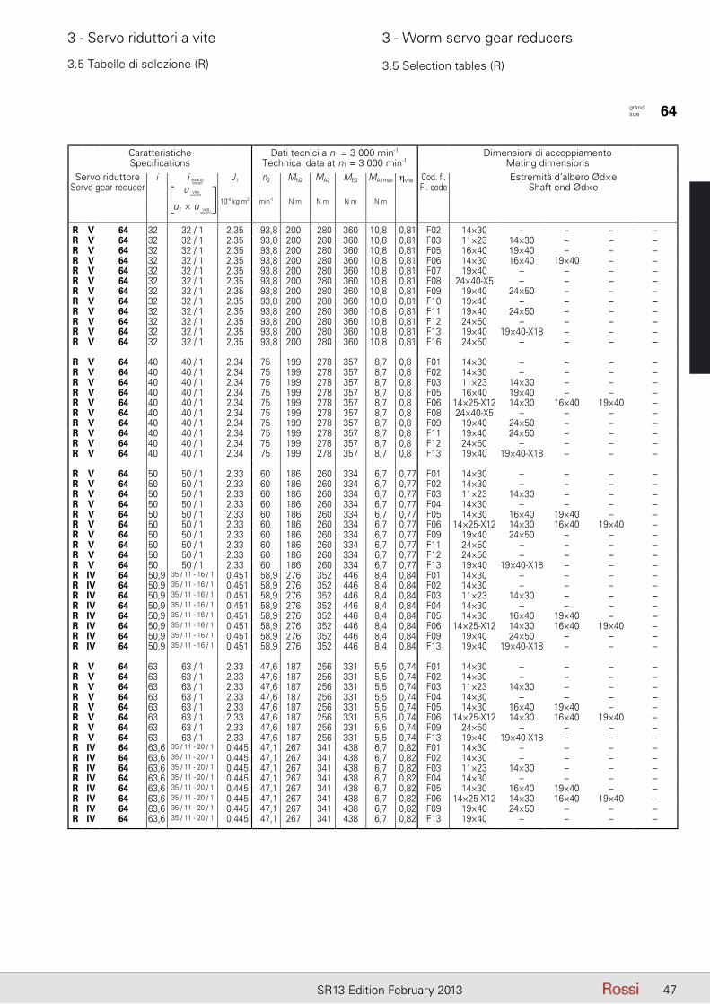
47SR13 Edition February 2013
3 - Servo riduttori a vite 3 - Worm servo gear reducers
CaratteristicheSpecifications
Dati tecnici a n1 = 3 000 min-1
Technical data at n1 = 3 000 min-1Dimensioni di accoppiamento
Mating dimensionsServo riduttore
Servo gear reduceri iesatto - exact J1 n2 MN2 MA2 ME2 MA1max ηvite Cod. fl.
Fl. codeEstremità d’albero Ød×e
Shaft end Ød×e10-4 kg m2 min-1 N m N m N m N m
R V 64 32 32 / 1 2,35 93,8 200 280 360 10,8 0,81 F02 14×30 – – – –R V 64 32 32 / 1 2,35 93,8 200 280 360 10,8 0,81 F03 11×23 14×30 – – –R V 64 32 32 / 1 2,35 93,8 200 280 360 10,8 0,81 F05 16×40 19×40 – – –R V 64 32 32 / 1 2,35 93,8 200 280 360 10,8 0,81 F06 14×30 16×40 19×40 – –R V 64 32 32 / 1 2,35 93,8 200 280 360 10,8 0,81 F07 19×40 – – – –R V 64 32 32 / 1 2,35 93,8 200 280 360 10,8 0,81 F08 24×40-X5 – – – –R V 64 32 32 / 1 2,35 93,8 200 280 360 10,8 0,81 F09 19×40 24×50 – – –R V 64 32 32 / 1 2,35 93,8 200 280 360 10,8 0,81 F10 19×40 – – – –R V 64 32 32 / 1 2,35 93,8 200 280 360 10,8 0,81 F11 19×40 24×50 – – –R V 64 32 32 / 1 2,35 93,8 200 280 360 10,8 0,81 F12 24×50 – – – –R V 64 32 32 / 1 2,35 93,8 200 280 360 10,8 0,81 F13 19×40 19×40-X18 – – –R V 64 32 32 / 1 2,35 93,8 200 280 360 10,8 0,81 F16 24×50 – – – –
R V 64 40 40 / 1 2,34 75 199 278 357 8,7 0,8 F01 14×30 – – – –R V 64 40 40 / 1 2,34 75 199 278 357 8,7 0,8 F02 14×30 – – – –R V 64 40 40 / 1 2,34 75 199 278 357 8,7 0,8 F03 11×23 14×30 – – –R V 64 40 40 / 1 2,34 75 199 278 357 8,7 0,8 F05 16×40 19×40 – – –R V 64 40 40 / 1 2,34 75 199 278 357 8,7 0,8 F06 14×25-X12 14×30 16×40 19×40 –R V 64 40 40 / 1 2,34 75 199 278 357 8,7 0,8 F08 24×40-X5 – – – –R V 64 40 40 / 1 2,34 75 199 278 357 8,7 0,8 F09 19×40 24×50 – – –R V 64 40 40 / 1 2,34 75 199 278 357 8,7 0,8 F11 19×40 24×50 – – –R V 64 40 40 / 1 2,34 75 199 278 357 8,7 0,8 F12 24×50 – – – –R V 64 40 40 / 1 2,34 75 199 278 357 8,7 0,8 F13 19×40 19×40-X18 – – –
R V 64 50 50 / 1 2,33 60 186 260 334 6,7 0,77 F01 14×30 – – – –R V 64 50 50 / 1 2,33 60 186 260 334 6,7 0,77 F02 14×30 – – – –R V 64 50 50 / 1 2,33 60 186 260 334 6,7 0,77 F03 11×23 14×30 – – –R V 64 50 50 / 1 2,33 60 186 260 334 6,7 0,77 F04 14×30 – – – –R V 64 50 50 / 1 2,33 60 186 260 334 6,7 0,77 F05 14×30 16×40 19×40 – –R V 64 50 50 / 1 2,33 60 186 260 334 6,7 0,77 F06 14×25-X12 14×30 16×40 19×40 –R V 64 50 50 / 1 2,33 60 186 260 334 6,7 0,77 F09 19×40 24×50 – – –R V 64 50 50 / 1 2,33 60 186 260 334 6,7 0,77 F11 24×50 – – – –R V 64 50 50 / 1 2,33 60 186 260 334 6,7 0,77 F12 24×50 – – – –R V 64 50 50 / 1 2,33 60 186 260 334 6,7 0,77 F13 19×40 19×40-X18 – – –R IV 64 50,9 35 / 11 - 16 / 1 0,451 58,9 276 352 446 8,4 0,84 F01 14×30 – – – –R IV 64 50,9 35 / 11 - 16 / 1 0,451 58,9 276 352 446 8,4 0,84 F02 14×30 – – – –R IV 64 50,9 35 / 11 - 16 / 1 0,451 58,9 276 352 446 8,4 0,84 F03 11×23 14×30 – – –R IV 64 50,9 35 / 11 - 16 / 1 0,451 58,9 276 352 446 8,4 0,84 F04 14×30 – – – –R IV 64 50,9 35 / 11 - 16 / 1 0,451 58,9 276 352 446 8,4 0,84 F05 14×30 16×40 19×40 – –R IV 64 50,9 35 / 11 - 16 / 1 0,451 58,9 276 352 446 8,4 0,84 F06 14×25-X12 14×30 16×40 19×40 –R IV 64 50,9 35 / 11 - 16 / 1 0,451 58,9 276 352 446 8,4 0,84 F09 19×40 24×50 – – –R IV 64 50,9 35 / 11 - 16 / 1 0,451 58,9 276 352 446 8,4 0,84 F13 19×40 19×40-X18 – – –
R V 64 63 63 / 1 2,33 47,6 187 256 331 5,5 0,74 F01 14×30 – – – –R V 64 63 63 / 1 2,33 47,6 187 256 331 5,5 0,74 F02 14×30 – – – –R V 64 63 63 / 1 2,33 47,6 187 256 331 5,5 0,74 F03 11×23 14×30 – – –R V 64 63 63 / 1 2,33 47,6 187 256 331 5,5 0,74 F04 14×30 – – – –R V 64 63 63 / 1 2,33 47,6 187 256 331 5,5 0,74 F05 14×30 16×40 19×40 – –R V 64 63 63 / 1 2,33 47,6 187 256 331 5,5 0,74 F06 14×25-X12 14×30 16×40 19×40 –R V 64 63 63 / 1 2,33 47,6 187 256 331 5,5 0,74 F09 24×50 – – – –R V 64 63 63 / 1 2,33 47,6 187 256 331 5,5 0,74 F13 19×40 19×40-X18 – – –R IV 64 63,6 35 / 11 - 20 / 1 0,445 47,1 267 341 438 6,7 0,82 F01 14×30 – – – –R IV 64 63,6 35 / 11 - 20 / 1 0,445 47,1 267 341 438 6,7 0,82 F02 14×30 – – – –R IV 64 63,6 35 / 11 - 20 / 1 0,445 47,1 267 341 438 6,7 0,82 F03 11×23 14×30 – – –R IV 64 63,6 35 / 11 - 20 / 1 0,445 47,1 267 341 438 6,7 0,82 F04 14×30 – – – –R IV 64 63,6 35 / 11 - 20 / 1 0,445 47,1 267 341 438 6,7 0,82 F05 14×30 16×40 19×40 – –R IV 64 63,6 35 / 11 - 20 / 1 0,445 47,1 267 341 438 6,7 0,82 F06 14×25-X12 14×30 16×40 19×40 –R IV 64 63,6 35 / 11 - 20 / 1 0,445 47,1 267 341 438 6,7 0,82 F09 19×40 24×50 – – –R IV 64 63,6 35 / 11 - 20 / 1 0,445 47,1 267 341 438 6,7 0,82 F13 19×40 – – – –
3.5 Tabelle di selezione (R) 3.5 Selection tables (R)
grand. size 64
i esatto
u
u1 × u
viteworm
viteworm
[ ]i esatto
exact
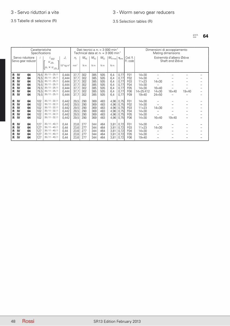
48 SR13 Edition February 2013
3 - Servo riduttori a vite 3 - Worm servo gear reducers
3.5 Tabelle di selezione (R) 3.5 Selection tables (R)
CaratteristicheSpecifications
Dati tecnici a n1 = 3 000 min-1
Technical data at n1 = 3 000 min-1Dimensioni di accoppiamento
Mating dimensionsServo riduttore
Servo gear reduceri iesatto - exact J1 n2 MN2 MA2 ME2 MA1max ηvite Cod. fl.
Fl. codeEstremità d’albero Ød×e
Shaft end Ød×e10-4 kg m2 min-1 N m N m N m N m
R IV 64 79,5 35 / 11 - 25 / 1 0,444 37,7 302 385 505 6,4 0,77 F01 14×30 – – – –R IV 64 79,5 35 / 11 - 25 / 1 0,444 37,7 302 385 505 6,4 0,77 F02 14×30 – – – –R IV 64 79,5 35 / 11 - 25 / 1 0,444 37,7 302 385 505 6,4 0,77 F03 11×23 14×30 – – –R IV 64 79,5 35 / 11 - 25 / 1 0,444 37,7 302 385 505 6,4 0,77 F04 14×30 – – – –R IV 64 79,5 35 / 11 - 25 / 1 0,444 37,7 302 385 505 6,4 0,77 F05 14×30 16×40 – – –R IV 64 79,5 35 / 11 - 25 / 1 0,444 37,7 302 385 505 6,4 0,77 F06 14×25-X12 14×30 16×40 19×40 –R IV 64 79,5 35 / 11 - 25 / 1 0,444 37,7 302 385 505 6,4 0,77 F09 19×40 24×50 – – –
R IV 64 102 35 / 11 - 32 / 1 0,442 29,5 290 369 483 4,96 0,75 F01 14×30 – – – –R IV 64 102 35 / 11 - 32 / 1 0,442 29,5 290 369 483 4,96 0,75 F02 14×30 – – – –R IV 64 102 35 / 11 - 32 / 1 0,442 29,5 290 369 483 4,96 0,75 F03 11×23 14×30 – – –R IV 64 102 35 / 11 - 32 / 1 0,442 29,5 290 369 483 4,96 0,75 F04 14×30 – – – –R IV 64 102 35 / 11 - 32 / 1 0,442 29,5 290 369 483 4,96 0,75 F05 14×30 – – – –R IV 64 102 35 / 11 - 32 / 1 0,442 29,5 290 369 483 4,96 0,75 F06 14×30 16×40 19×40 – –
R IV 64 127 35 / 11 - 40 / 1 0,44 23,6 277 344 464 3,81 0,72 F01 14×30 – – – –R IV 64 127 35 / 11 - 40 / 1 0,44 23,6 277 344 464 3,81 0,72 F03 11×23 14×30 – – –R IV 64 127 35 / 11 - 40 / 1 0,44 23,6 277 344 464 3,81 0,72 F04 14×30 – – – –R IV 64 127 35 / 11 - 40 / 1 0,44 23,6 277 344 464 3,81 0,72 F05 14×30 – – – –R IV 64 127 35 / 11 - 40 / 1 0,44 23,6 277 344 464 3,81 0,72 F06 19×40 – – – –
grand. size 64
i esatto
u
u1 × u
viteworm
viteworm
[ ]i esatto
exact
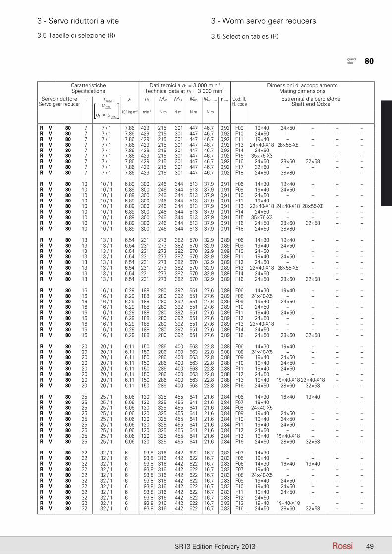
49SR13 Edition February 2013
3 - Servo riduttori a vite 3 - Worm servo gear reducers
3.5 Tabelle di selezione (R) 3.5 Selection tables (R)
CaratteristicheSpecifications
Dati tecnici a n1 = 3 000 min-1
Technical data at n1 = 3 000 min-1Dimensioni di accoppiamento
Mating dimensionsServo riduttore
Servo gear reduceri iesatto - exact J1 n2 MN2 MA2 ME2 MA1max ηvite Cod. fl.
Fl. codeEstremità d’albero Ød×e
Shaft end Ød×e10-4 kg m2 min-1 N m N m N m N m
R V 80 7 7 / 1 7,86 429 215 301 447 46,7 0,92 F09 19×40 24×50 – – –R V 80 7 7 / 1 7,86 429 215 301 447 46,7 0,92 F10 24×50 – – – –R V 80 7 7 / 1 7,86 429 215 301 447 46,7 0,92 F11 19×40 – – – –R V 80 7 7 / 1 7,86 429 215 301 447 46,7 0,92 F13 24×40-X18 28×55-X8 – – –R V 80 7 7 / 1 7,86 429 215 301 447 46,7 0,92 F14 24×50 – – – –R V 80 7 7 / 1 7,86 429 215 301 447 46,7 0,92 F15 35×76-X3 – – – –R V 80 7 7 / 1 7,86 429 215 301 447 46,7 0,92 F16 24×50 28×60 32×58 – –R V 80 7 7 / 1 7,86 429 215 301 447 46,7 0,92 F17 32×60 – – – –R V 80 7 7 / 1 7,86 429 215 301 447 46,7 0,92 F18 24×50 38×80 – – –
R V 80 10 10 / 1 6,89 300 246 344 513 37,9 0,91 F06 14×30 19×40 – – –R V 80 10 10 / 1 6,89 300 246 344 513 37,9 0,91 F09 19×40 24×50 – – –R V 80 10 10 / 1 6,89 300 246 344 513 37,9 0,91 F10 24×50 – – – –R V 80 10 10 / 1 6,89 300 246 344 513 37,9 0,91 F11 19×40 – – – –R V 80 10 10 / 1 6,89 300 246 344 513 37,9 0,91 F13 22×40-X18 24×40-X18 28×55-X8 – –R V 80 10 10 / 1 6,89 300 246 344 513 37,9 0,91 F14 24×50 – – – –R V 80 10 10 / 1 6,89 300 246 344 513 37,9 0,91 F15 35×76-X3 – – – –R V 80 10 10 / 1 6,89 300 246 344 513 37,9 0,91 F16 24×50 28×60 32×58 – –R V 80 10 10 / 1 6,89 300 246 344 513 37,9 0,91 F18 24×50 38×80 – – –
R V 80 13 13 / 1 6,54 231 273 382 570 32,9 0,89 F06 14×30 19×40 – – –R V 80 13 13 / 1 6,54 231 273 382 570 32,9 0,89 F09 19×40 24×50 – – –R V 80 13 13 / 1 6,54 231 273 382 570 32,9 0,89 F10 24×50 – – – –R V 80 13 13 / 1 6,54 231 273 382 570 32,9 0,89 F11 19×40 24×50 – – –R V 80 13 13 / 1 6,54 231 273 382 570 32,9 0,89 F12 24×50 – – – –R V 80 13 13 / 1 6,54 231 273 382 570 32,9 0,89 F13 22×40-X18 28×55-X8 – – –R V 80 13 13 / 1 6,54 231 273 382 570 32,9 0,89 F14 24×50 – – – –R V 80 13 13 / 1 6,54 231 273 382 570 32,9 0,89 F16 24×50 28×60 32×58 – –
R V 80 16 16 / 1 6,29 188 280 392 551 27,6 0,89 F06 14×30 19×40 – – –R V 80 16 16 / 1 6,29 188 280 392 551 27,6 0,89 F08 24×40-X5 – – – –R V 80 16 16 / 1 6,29 188 280 392 551 27,6 0,89 F09 19×40 24×50 – – –R V 80 16 16 / 1 6,29 188 280 392 551 27,6 0,89 F10 24×50 – – – –R V 80 16 16 / 1 6,29 188 280 392 551 27,6 0,89 F11 19×40 24×50 – – –R V 80 16 16 / 1 6,29 188 280 392 551 27,6 0,89 F12 24×50 – – – –R V 80 16 16 / 1 6,29 188 280 392 551 27,6 0,89 F13 22×40-X18 – – – –R V 80 16 16 / 1 6,29 188 280 392 551 27,6 0,89 F14 24×50 – – – –R V 80 16 16 / 1 6,29 188 280 392 551 27,6 0,89 F16 24×50 28×60 32×58 – –
R V 80 20 20 / 1 6,11 150 286 400 563 22,8 0,88 F06 14×30 19×40 – – –R V 80 20 20 / 1 6,11 150 286 400 563 22,8 0,88 F08 24×40-X5 – – – –R V 80 20 20 / 1 6,11 150 286 400 563 22,8 0,88 F09 19×40 24×50 – – –R V 80 20 20 / 1 6,11 150 286 400 563 22,8 0,88 F10 19×40 24×50 – – –R V 80 20 20 / 1 6,11 150 286 400 563 22,8 0,88 F11 19×40 24×50 – – –R V 80 20 20 / 1 6,11 150 286 400 563 22,8 0,88 F12 24×50 – – – –R V 80 20 20 / 1 6,11 150 286 400 563 22,8 0,88 F13 19×40 19×40-X18 22×40-X18 – –R V 80 20 20 / 1 6,11 150 286 400 563 22,8 0,88 F16 24×50 28×60 32×58 – –
R V 80 25 25 / 1 6,06 120 325 455 641 21,6 0,84 F06 14×30 16×40 19×40 – –R V 80 25 25 / 1 6,06 120 325 455 641 21,6 0,84 F07 19×40 – – – –R V 80 25 25 / 1 6,06 120 325 455 641 21,6 0,84 F08 24×40-X5 – – – –R V 80 25 25 / 1 6,06 120 325 455 641 21,6 0,84 F09 19×40 24×50 – – –R V 80 25 25 / 1 6,06 120 325 455 641 21,6 0,84 F10 19×40 24×50 – – –R V 80 25 25 / 1 6,06 120 325 455 641 21,6 0,84 F11 19×40 24×50 – – –R V 80 25 25 / 1 6,06 120 325 455 641 21,6 0,84 F12 24×50 – – – –R V 80 25 25 / 1 6,06 120 325 455 641 21,6 0,84 F13 19×40 19×40-X18 – – –R V 80 25 25 / 1 6,06 120 325 455 641 21,6 0,84 F16 24×50 28×60 32×58 – –
R V 80 32 32 / 1 6 93,8 316 442 622 16,7 0,83 F03 14×30 – – – –R V 80 32 32 / 1 6 93,8 316 442 622 16,7 0,83 F05 19×40 – – – –R V 80 32 32 / 1 6 93,8 316 442 622 16,7 0,83 F06 14×30 16×40 19×40 – –R V 80 32 32 / 1 6 93,8 316 442 622 16,7 0,83 F07 19×40 – – – –R V 80 32 32 / 1 6 93,8 316 442 622 16,7 0,83 F08 24×40-X5 – – – –R V 80 32 32 / 1 6 93,8 316 442 622 16,7 0,83 F09 19×40 24×50 – – –R V 80 32 32 / 1 6 93,8 316 442 622 16,7 0,83 F10 19×40 24×50 – – –R V 80 32 32 / 1 6 93,8 316 442 622 16,7 0,83 F11 19×40 24×50 – – –R V 80 32 32 / 1 6 93,8 316 442 622 16,7 0,83 F12 24×50 – – – –R V 80 32 32 / 1 6 93,8 316 442 622 16,7 0,83 F13 19×40 19×40-X18 – – –R V 80 32 32 / 1 6 93,8 316 442 622 16,7 0,83 F16 24×50 28×60 32×58 – –
grand. size 80
i esatto
u
u1 × u
viteworm
viteworm
[ ]i esatto
exact
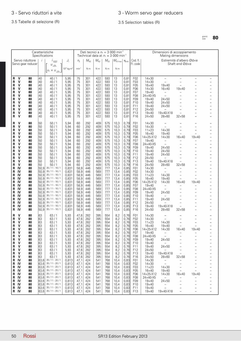
50 SR13 Edition February 2013
3 - Servo riduttori a vite 3 - Worm servo gear reducers
3.5 Tabelle di selezione (R) 3.5 Selection tables (R)
CaratteristicheSpecifications
Dati tecnici a n1 = 3 000 min-1
Technical data at n1 = 3 000 min-1Dimensioni di accoppiamento
Mating dimensionsServo riduttore
Servo gear reduceri iesatto - exact J1 n2 MN2 MA2 ME2 MA1max ηvite Cod. fl.
Fl. codeEstremità d’albero Ød×e
Shaft end Ød×e10-4 kg m2 min-1 N m N m N m N m
R V 80 40 40 / 1 5,95 75 301 422 593 13 0,81 F02 14×30 – – – –R V 80 40 40 / 1 5,95 75 301 422 593 13 0,81 F03 14×30 – – – –R V 80 40 40 / 1 5,95 75 301 422 593 13 0,81 F05 16×40 19×40 – – –R V 80 40 40 / 1 5,95 75 301 422 593 13 0,81 F06 14×30 16×40 19×40 – –R V 80 40 40 / 1 5,95 75 301 422 593 13 0,81 F07 19×40 – – – –R V 80 40 40 / 1 5,95 75 301 422 593 13 0,81 F08 24×40-X5 – – – –R V 80 40 40 / 1 5,95 75 301 422 593 13 0,81 F09 19×40 24×50 – – –R V 80 40 40 / 1 5,95 75 301 422 593 13 0,81 F10 19×40 24×50 – – –R V 80 40 40 / 1 5,95 75 301 422 593 13 0,81 F11 19×40 24×50 – – –R V 80 40 40 / 1 5,95 75 301 422 593 13 0,81 F12 24×50 – – – –R V 80 40 40 / 1 5,95 75 301 422 593 13 0,81 F13 19×40 19×40-X18 – – –R V 80 40 40 / 1 5,95 75 301 422 593 13 0,81 F16 24×50 28×60 32×58 – –
R V 80 50 50 / 1 5,94 60 292 409 575 10,3 0,79 F01 14×30 – – – –R V 80 50 50 / 1 5,94 60 292 409 575 10,3 0,79 F02 14×30 – – – –R V 80 50 50 / 1 5,94 60 292 409 575 10,3 0,79 F03 11×23 14×30 – – –R V 80 50 50 / 1 5,94 60 292 409 575 10,3 0,79 F05 16×40 19×40 – – –R V 80 50 50 / 1 5,94 60 292 409 575 10,3 0,79 F06 14×25-X12 14×30 16×40 19×40 –R V 80 50 50 / 1 5,94 60 292 409 575 10,3 0,79 F07 19×40 – – – –R V 80 50 50 / 1 5,94 60 292 409 575 10,3 0,79 F08 24×40-X5 – – – –R V 80 50 50 / 1 5,94 60 292 409 575 10,3 0,79 F09 19×40 24×50 – – –R V 80 50 50 / 1 5,94 60 292 409 575 10,3 0,79 F10 19×40 24×50 – – –R V 80 50 50 / 1 5,94 60 292 409 575 10,3 0,79 F11 19×40 24×50 – – –R V 80 50 50 / 1 5,94 60 292 409 575 10,3 0,79 F12 24×50 – – – –R V 80 50 50 / 1 5,94 60 292 409 575 10,3 0,79 F13 19×40 19×40-X18 – – –R V 80 50 50 / 1 5,94 60 292 409 575 10,3 0,79 F16 24×50 28×60 32×58 – –R IV 80 50,9 35 / 11 - 16 / 1 0,831 58,9 446 569 777 13,4 0,85 F01 14×30 – – – –R IV 80 50,9 35 / 11 - 16 / 1 0,831 58,9 446 569 777 13,4 0,85 F02 14×30 – – – –R IV 80 50,9 35 / 11 - 16 / 1 0,831 58,9 446 569 777 13,4 0,85 F03 11×23 14×30 – – –R IV 80 50,9 35 / 11 - 16 / 1 0,831 58,9 446 569 777 13,4 0,85 F05 16×40 19×40 – – –R IV 80 50,9 35 / 11 - 16 / 1 0,831 58,9 446 569 777 13,4 0,85 F06 14×25-X12 14×30 16×40 19×40 –R IV 80 50,9 35 / 11 - 16 / 1 0,831 58,9 446 569 777 13,4 0,85 F07 19×40 – – – –R IV 80 50,9 35 / 11 - 16 / 1 0,831 58,9 446 569 777 13,4 0,85 F08 24×40-X5 – – – –R IV 80 50,9 35 / 11 - 16 / 1 0,831 58,9 446 569 777 13,4 0,85 F09 19×40 24×50 – – –R IV 80 50,9 35 / 11 - 16 / 1 0,831 58,9 446 569 777 13,4 0,85 F10 19×40 – – – –R IV 80 50,9 35 / 11 - 16 / 1 0,831 58,9 446 569 777 13,4 0,85 F11 19×40 24×50 – – –R IV 80 50,9 35 / 11 - 16 / 1 0,831 58,9 446 569 777 13,4 0,85 F12 24×50 – – – –R IV 80 50,9 35 / 11 - 16 / 1 0,831 58,9 446 569 777 13,4 0,85 F13 19×40 19×40-X18 – – –R IV 80 50,9 35 / 11 - 16 / 1 0,831 58,9 446 569 777 13,4 0,85 F16 24×50 28×60 32×58 – –
R V 80 63 63 / 1 5,93 47,6 282 395 554 8,2 0,76 F01 14×30 – – – –R V 80 63 63 / 1 5,93 47,6 282 395 554 8,2 0,76 F02 14×30 – – – –R V 80 63 63 / 1 5,93 47,6 282 395 554 8,2 0,76 F03 11×23 14×30 – – –R V 80 63 63 / 1 5,93 47,6 282 395 554 8,2 0,76 F05 16×40 19×40 – – –R V 80 63 63 / 1 5,93 47,6 282 395 554 8,2 0,76 F06 14×25-X12 14×30 16×40 19×40 –R V 80 63 63 / 1 5,93 47,6 282 395 554 8,2 0,76 F07 19×40 – – – –R V 80 63 63 / 1 5,93 47,6 282 395 554 8,2 0,76 F08 24×40-X5 – – – –R V 80 63 63 / 1 5,93 47,6 282 395 554 8,2 0,76 F09 19×40 24×50 – – –R V 80 63 63 / 1 5,93 47,6 282 395 554 8,2 0,76 F10 19×40 – – – –R V 80 63 63 / 1 5,93 47,6 282 395 554 8,2 0,76 F11 19×40 24×50 – – –R V 80 63 63 / 1 5,93 47,6 282 395 554 8,2 0,76 F12 24×50 – – – –R V 80 63 63 / 1 5,93 47,6 282 395 554 8,2 0,76 F13 19×40 19×40-X18 – – –R V 80 63 63 / 1 5,93 47,6 282 395 554 8,2 0,76 F16 24×50 28×60 32×58 – –R IV 80 63,6 35 / 11 - 20 / 1 0,813 47,1 424 541 768 10,4 0,83 F01 14×30 – – – –R IV 80 63,6 35 / 11 - 20 / 1 0,813 47,1 424 541 768 10,4 0,83 F02 14×30 – – – –R IV 80 63,6 35 / 11 - 20 / 1 0,813 47,1 424 541 768 10,4 0,83 F03 11×23 14×30 – – –R IV 80 63,6 35 / 11 - 20 / 1 0,813 47,1 424 541 768 10,4 0,83 F05 16×40 19×40 – – –R IV 80 63,6 35 / 11 - 20 / 1 0,813 47,1 424 541 768 10,4 0,83 F06 14×25-X12 14×30 16×40 19×40 –R IV 80 63,6 35 / 11 - 20 / 1 0,813 47,1 424 541 768 10,4 0,83 F08 24×40-X5 – – – –R IV 80 63,6 35 / 11 - 20 / 1 0,813 47,1 424 541 768 10,4 0,83 F09 19×40 24×50 – – –R IV 80 63,6 35 / 11 - 20 / 1 0,813 47,1 424 541 768 10,4 0,83 F10 19×40 – – – –R IV 80 63,6 35 / 11 - 20 / 1 0,813 47,1 424 541 768 10,4 0,83 F11 19×40 – – – –R IV 80 63,6 35 / 11 - 20 / 1 0,813 47,1 424 541 768 10,4 0,83 F13 19×40 19×40-X18 – – –
grand. size 80
i esatto
u
u1 × u
viteworm
viteworm
[ ]i esatto
exact
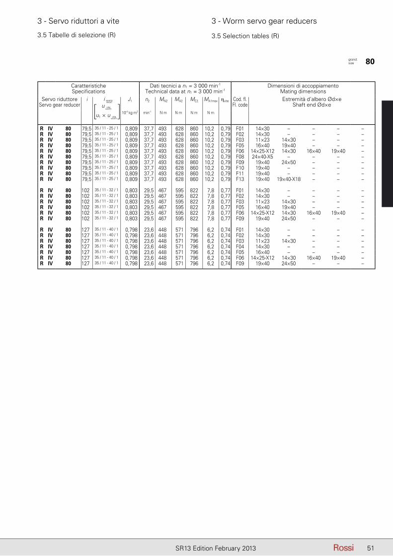
51SR13 Edition February 2013
3 - Servo riduttori a vite 3 - Worm servo gear reducers
CaratteristicheSpecifications
Dati tecnici a n1 = 3 000 min-1
Technical data at n1 = 3 000 min-1Dimensioni di accoppiamento
Mating dimensionsServo riduttore
Servo gear reduceri iesatto - exact J1 n2 MN2 MA2 ME2 MA1max ηvite Cod. fl.
Fl. codeEstremità d’albero Ød×e
Shaft end Ød×e10-4 kg m2 min-1 N m N m N m N m
R IV 80 79,5 35 / 11 - 25 / 1 0,809 37,7 493 628 860 10,2 0,79 F01 14×30 – – – –R IV 80 79,5 35 / 11 - 25 / 1 0,809 37,7 493 628 860 10,2 0,79 F02 14×30 – – – –R IV 80 79,5 35 / 11 - 25 / 1 0,809 37,7 493 628 860 10,2 0,79 F03 11×23 14×30 – – –R IV 80 79,5 35 / 11 - 25 / 1 0,809 37,7 493 628 860 10,2 0,79 F05 16×40 19×40 – – –R IV 80 79,5 35 / 11 - 25 / 1 0,809 37,7 493 628 860 10,2 0,79 F06 14×25-X12 14×30 16×40 19×40 –R IV 80 79,5 35 / 11 - 25 / 1 0,809 37,7 493 628 860 10,2 0,79 F08 24×40-X5 – – – –R IV 80 79,5 35 / 11 - 25 / 1 0,809 37,7 493 628 860 10,2 0,79 F09 19×40 24×50 – – –R IV 80 79,5 35 / 11 - 25 / 1 0,809 37,7 493 628 860 10,2 0,79 F10 19×40 – – – –R IV 80 79,5 35 / 11 - 25 / 1 0,809 37,7 493 628 860 10,2 0,79 F11 19×40 – – – –R IV 80 79,5 35 / 11 - 25 / 1 0,809 37,7 493 628 860 10,2 0,79 F13 19×40 19×40-X18 – – –
R IV 80 102 35 / 11 - 32 / 1 0,803 29,5 467 595 822 7,8 0,77 F01 14×30 – – – –R IV 80 102 35 / 11 - 32 / 1 0,803 29,5 467 595 822 7,8 0,77 F02 14×30 – – – –R IV 80 102 35 / 11 - 32 / 1 0,803 29,5 467 595 822 7,8 0,77 F03 11×23 14×30 – – –R IV 80 102 35 / 11 - 32 / 1 0,803 29,5 467 595 822 7,8 0,77 F05 16×40 19×40 – – –R IV 80 102 35 / 11 - 32 / 1 0,803 29,5 467 595 822 7,8 0,77 F06 14×25-X12 14×30 16×40 19×40 –R IV 80 102 35 / 11 - 32 / 1 0,803 29,5 467 595 822 7,8 0,77 F09 19×40 24×50 – – –
R IV 80 127 35 / 11 - 40 / 1 0,798 23,6 448 571 796 6,2 0,74 F01 14×30 – – – –R IV 80 127 35 / 11 - 40 / 1 0,798 23,6 448 571 796 6,2 0,74 F02 14×30 – – – –R IV 80 127 35 / 11 - 40 / 1 0,798 23,6 448 571 796 6,2 0,74 F03 11×23 14×30 – – –R IV 80 127 35 / 11 - 40 / 1 0,798 23,6 448 571 796 6,2 0,74 F04 14×30 – – – –R IV 80 127 35 / 11 - 40 / 1 0,798 23,6 448 571 796 6,2 0,74 F05 16×40 – – – –R IV 80 127 35 / 11 - 40 / 1 0,798 23,6 448 571 796 6,2 0,74 F06 14×25-X12 14×30 16×40 19×40 –R IV 80 127 35 / 11 - 40 / 1 0,798 23,6 448 571 796 6,2 0,74 F09 19×40 24×50 – – –
3.5 Tabelle di selezione (R) 3.5 Selection tables (R)
grand. size 80
i esatto
u
u1 × u
viteworm
viteworm
[ ]i esatto
exact
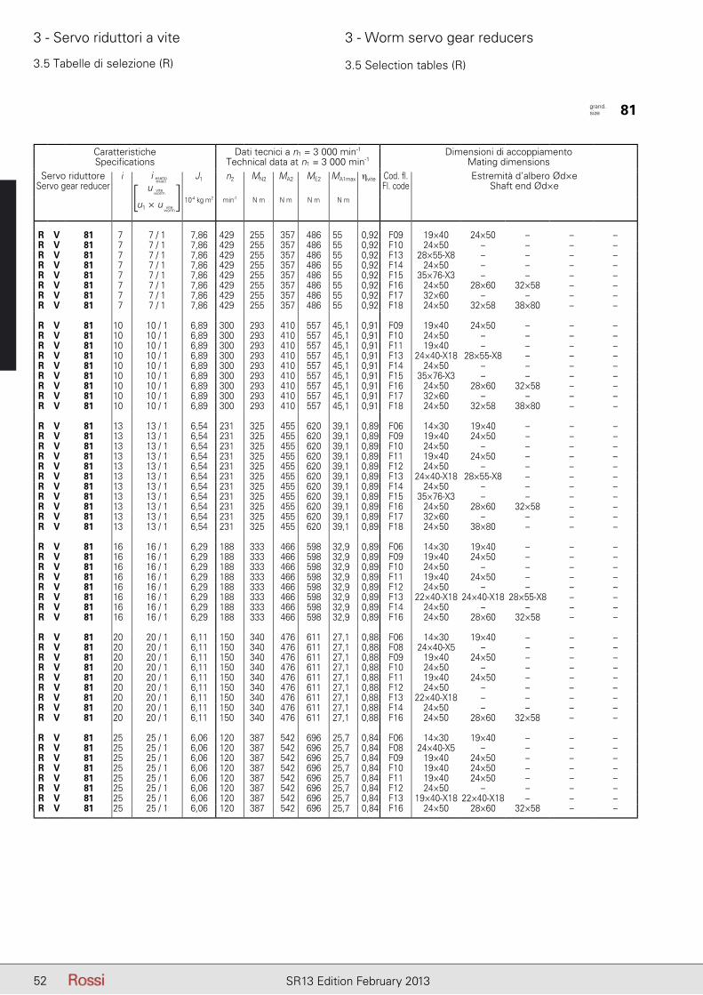
52 SR13 Edition February 2013
3 - Servo riduttori a vite 3 - Worm servo gear reducers
3.5 Tabelle di selezione (R) 3.5 Selection tables (R)
CaratteristicheSpecifications
Dati tecnici a n1 = 3 000 min-1
Technical data at n1 = 3 000 min-1Dimensioni di accoppiamento
Mating dimensionsServo riduttore
Servo gear reduceri iesatto - exact J1 n2 MN2 MA2 ME2 MA1max ηvite Cod. fl.
Fl. codeEstremità d’albero Ød×e
Shaft end Ød×e10-4 kg m2 min-1 N m N m N m N m
R V 81 7 7 / 1 7,86 429 255 357 486 55 0,92 F09 19×40 24×50 – – –R V 81 7 7 / 1 7,86 429 255 357 486 55 0,92 F10 24×50 – – – –R V 81 7 7 / 1 7,86 429 255 357 486 55 0,92 F13 28×55-X8 – – – –R V 81 7 7 / 1 7,86 429 255 357 486 55 0,92 F14 24×50 – – – –R V 81 7 7 / 1 7,86 429 255 357 486 55 0,92 F15 35×76-X3 – – – –R V 81 7 7 / 1 7,86 429 255 357 486 55 0,92 F16 24×50 28×60 32×58 – –R V 81 7 7 / 1 7,86 429 255 357 486 55 0,92 F17 32×60 – – – –R V 81 7 7 / 1 7,86 429 255 357 486 55 0,92 F18 24×50 32×58 38×80 – –
R V 81 10 10 / 1 6,89 300 293 410 557 45,1 0,91 F09 19×40 24×50 – – –R V 81 10 10 / 1 6,89 300 293 410 557 45,1 0,91 F10 24×50 – – – –R V 81 10 10 / 1 6,89 300 293 410 557 45,1 0,91 F11 19×40 – – – –R V 81 10 10 / 1 6,89 300 293 410 557 45,1 0,91 F13 24×40-X18 28×55-X8 – – –R V 81 10 10 / 1 6,89 300 293 410 557 45,1 0,91 F14 24×50 – – – –R V 81 10 10 / 1 6,89 300 293 410 557 45,1 0,91 F15 35×76-X3 – – – –R V 81 10 10 / 1 6,89 300 293 410 557 45,1 0,91 F16 24×50 28×60 32×58 – –R V 81 10 10 / 1 6,89 300 293 410 557 45,1 0,91 F17 32×60 – – – –R V 81 10 10 / 1 6,89 300 293 410 557 45,1 0,91 F18 24×50 32×58 38×80 – –
R V 81 13 13 / 1 6,54 231 325 455 620 39,1 0,89 F06 14×30 19×40 – – –R V 81 13 13 / 1 6,54 231 325 455 620 39,1 0,89 F09 19×40 24×50 – – –R V 81 13 13 / 1 6,54 231 325 455 620 39,1 0,89 F10 24×50 – – – –R V 81 13 13 / 1 6,54 231 325 455 620 39,1 0,89 F11 19×40 24×50 – – –R V 81 13 13 / 1 6,54 231 325 455 620 39,1 0,89 F12 24×50 – – – –R V 81 13 13 / 1 6,54 231 325 455 620 39,1 0,89 F13 24×40-X18 28×55-X8 – – –R V 81 13 13 / 1 6,54 231 325 455 620 39,1 0,89 F14 24×50 – – – –R V 81 13 13 / 1 6,54 231 325 455 620 39,1 0,89 F15 35×76-X3 – – – –R V 81 13 13 / 1 6,54 231 325 455 620 39,1 0,89 F16 24×50 28×60 32×58 – –R V 81 13 13 / 1 6,54 231 325 455 620 39,1 0,89 F17 32×60 – – – –R V 81 13 13 / 1 6,54 231 325 455 620 39,1 0,89 F18 24×50 38×80 – – –
R V 81 16 16 / 1 6,29 188 333 466 598 32,9 0,89 F06 14×30 19×40 – – –R V 81 16 16 / 1 6,29 188 333 466 598 32,9 0,89 F09 19×40 24×50 – – –R V 81 16 16 / 1 6,29 188 333 466 598 32,9 0,89 F10 24×50 – – – –R V 81 16 16 / 1 6,29 188 333 466 598 32,9 0,89 F11 19×40 24×50 – – –R V 81 16 16 / 1 6,29 188 333 466 598 32,9 0,89 F12 24×50 – – – –R V 81 16 16 / 1 6,29 188 333 466 598 32,9 0,89 F13 22×40-X18 24×40-X18 28×55-X8 – –R V 81 16 16 / 1 6,29 188 333 466 598 32,9 0,89 F14 24×50 – – – –R V 81 16 16 / 1 6,29 188 333 466 598 32,9 0,89 F16 24×50 28×60 32×58 – –
R V 81 20 20 / 1 6,11 150 340 476 611 27,1 0,88 F06 14×30 19×40 – – –R V 81 20 20 / 1 6,11 150 340 476 611 27,1 0,88 F08 24×40-X5 – – – –R V 81 20 20 / 1 6,11 150 340 476 611 27,1 0,88 F09 19×40 24×50 – – –R V 81 20 20 / 1 6,11 150 340 476 611 27,1 0,88 F10 24×50 – – – –R V 81 20 20 / 1 6,11 150 340 476 611 27,1 0,88 F11 19×40 24×50 – – –R V 81 20 20 / 1 6,11 150 340 476 611 27,1 0,88 F12 24×50 – – – –R V 81 20 20 / 1 6,11 150 340 476 611 27,1 0,88 F13 22×40-X18 – – – –R V 81 20 20 / 1 6,11 150 340 476 611 27,1 0,88 F14 24×50 – – – –R V 81 20 20 / 1 6,11 150 340 476 611 27,1 0,88 F16 24×50 28×60 32×58 – –
R V 81 25 25 / 1 6,06 120 387 542 696 25,7 0,84 F06 14×30 19×40 – – –R V 81 25 25 / 1 6,06 120 387 542 696 25,7 0,84 F08 24×40-X5 – – – –R V 81 25 25 / 1 6,06 120 387 542 696 25,7 0,84 F09 19×40 24×50 – – –R V 81 25 25 / 1 6,06 120 387 542 696 25,7 0,84 F10 19×40 24×50 – – –R V 81 25 25 / 1 6,06 120 387 542 696 25,7 0,84 F11 19×40 24×50 – – –R V 81 25 25 / 1 6,06 120 387 542 696 25,7 0,84 F12 24×50 – – – –R V 81 25 25 / 1 6,06 120 387 542 696 25,7 0,84 F13 19×40-X18 22×40-X18 – – –R V 81 25 25 / 1 6,06 120 387 542 696 25,7 0,84 F16 24×50 28×60 32×58 – –
grand. size 81
i esatto
u
u1 × u
viteworm
viteworm
[ ]i esatto
exact
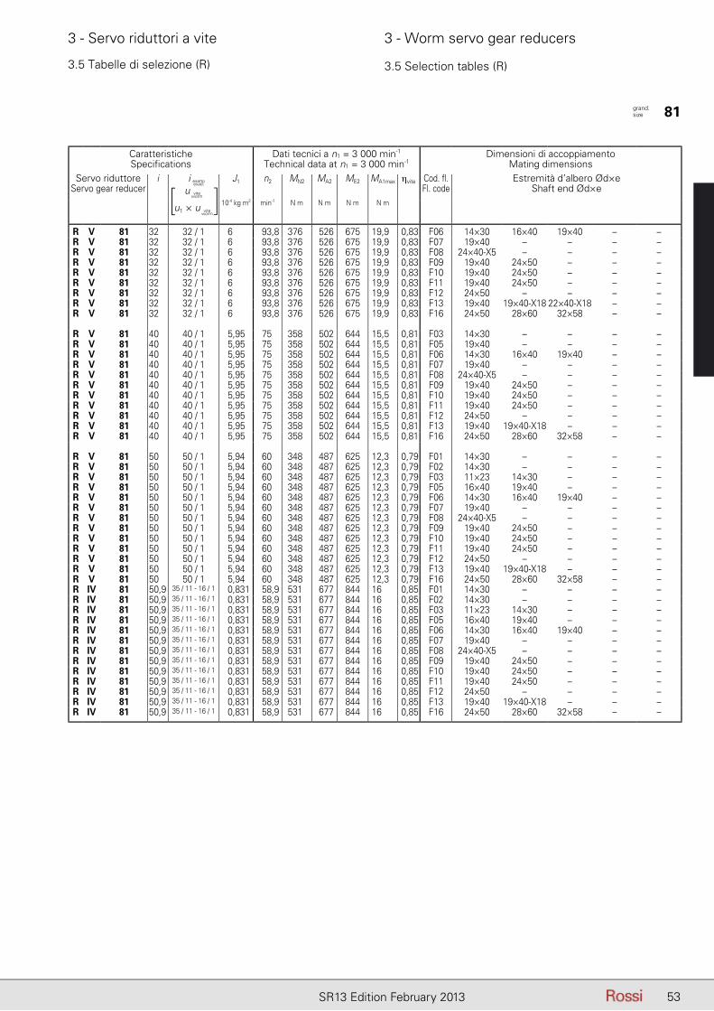
53SR13 Edition February 2013
3 - Servo riduttori a vite 3 - Worm servo gear reducers
3.5 Tabelle di selezione (R) 3.5 Selection tables (R)
CaratteristicheSpecifications
Dati tecnici a n1 = 3 000 min-1
Technical data at n1 = 3 000 min-1Dimensioni di accoppiamento
Mating dimensionsServo riduttore
Servo gear reduceri iesatto - exact J1 n2 MN2 MA2 ME2 MA1max ηvite Cod. fl.
Fl. codeEstremità d’albero Ød×e
Shaft end Ød×e10-4 kg m2 min-1 N m N m N m N m
R V 81 32 32 / 1 6 93,8 376 526 675 19,9 0,83 F06 14×30 16×40 19×40 – –R V 81 32 32 / 1 6 93,8 376 526 675 19,9 0,83 F07 19×40 – – – –R V 81 32 32 / 1 6 93,8 376 526 675 19,9 0,83 F08 24×40-X5 – – – –R V 81 32 32 / 1 6 93,8 376 526 675 19,9 0,83 F09 19×40 24×50 – – –R V 81 32 32 / 1 6 93,8 376 526 675 19,9 0,83 F10 19×40 24×50 – – –R V 81 32 32 / 1 6 93,8 376 526 675 19,9 0,83 F11 19×40 24×50 – – –R V 81 32 32 / 1 6 93,8 376 526 675 19,9 0,83 F12 24×50 – – – –R V 81 32 32 / 1 6 93,8 376 526 675 19,9 0,83 F13 19×40 19×40-X18 22×40-X18 – –R V 81 32 32 / 1 6 93,8 376 526 675 19,9 0,83 F16 24×50 28×60 32×58 – –
R V 81 40 40 / 1 5,95 75 358 502 644 15,5 0,81 F03 14×30 – – – –R V 81 40 40 / 1 5,95 75 358 502 644 15,5 0,81 F05 19×40 – – – –R V 81 40 40 / 1 5,95 75 358 502 644 15,5 0,81 F06 14×30 16×40 19×40 – –R V 81 40 40 / 1 5,95 75 358 502 644 15,5 0,81 F07 19×40 – – – –R V 81 40 40 / 1 5,95 75 358 502 644 15,5 0,81 F08 24×40-X5 – – – –R V 81 40 40 / 1 5,95 75 358 502 644 15,5 0,81 F09 19×40 24×50 – – –R V 81 40 40 / 1 5,95 75 358 502 644 15,5 0,81 F10 19×40 24×50 – – –R V 81 40 40 / 1 5,95 75 358 502 644 15,5 0,81 F11 19×40 24×50 – – –R V 81 40 40 / 1 5,95 75 358 502 644 15,5 0,81 F12 24×50 – – – –R V 81 40 40 / 1 5,95 75 358 502 644 15,5 0,81 F13 19×40 19×40-X18 – – –R V 81 40 40 / 1 5,95 75 358 502 644 15,5 0,81 F16 24×50 28×60 32×58 – –
R V 81 50 50 / 1 5,94 60 348 487 625 12,3 0,79 F01 14×30 – – – –R V 81 50 50 / 1 5,94 60 348 487 625 12,3 0,79 F02 14×30 – – – –R V 81 50 50 / 1 5,94 60 348 487 625 12,3 0,79 F03 11×23 14×30 – – –R V 81 50 50 / 1 5,94 60 348 487 625 12,3 0,79 F05 16×40 19×40 – – –R V 81 50 50 / 1 5,94 60 348 487 625 12,3 0,79 F06 14×30 16×40 19×40 – –R V 81 50 50 / 1 5,94 60 348 487 625 12,3 0,79 F07 19×40 – – – –R V 81 50 50 / 1 5,94 60 348 487 625 12,3 0,79 F08 24×40-X5 – – – –R V 81 50 50 / 1 5,94 60 348 487 625 12,3 0,79 F09 19×40 24×50 – – –R V 81 50 50 / 1 5,94 60 348 487 625 12,3 0,79 F10 19×40 24×50 – – –R V 81 50 50 / 1 5,94 60 348 487 625 12,3 0,79 F11 19×40 24×50 – – –R V 81 50 50 / 1 5,94 60 348 487 625 12,3 0,79 F12 24×50 – – – –R V 81 50 50 / 1 5,94 60 348 487 625 12,3 0,79 F13 19×40 19×40-X18 – – –R V 81 50 50 / 1 5,94 60 348 487 625 12,3 0,79 F16 24×50 28×60 32×58 – –R IV 81 50,9 35 / 11 - 16 / 1 0,831 58,9 531 677 844 16 0,85 F01 14×30 – – – –R IV 81 50,9 35 / 11 - 16 / 1 0,831 58,9 531 677 844 16 0,85 F02 14×30 – – – –R IV 81 50,9 35 / 11 - 16 / 1 0,831 58,9 531 677 844 16 0,85 F03 11×23 14×30 – – –R IV 81 50,9 35 / 11 - 16 / 1 0,831 58,9 531 677 844 16 0,85 F05 16×40 19×40 – – –R IV 81 50,9 35 / 11 - 16 / 1 0,831 58,9 531 677 844 16 0,85 F06 14×30 16×40 19×40 – –R IV 81 50,9 35 / 11 - 16 / 1 0,831 58,9 531 677 844 16 0,85 F07 19×40 – – – –R IV 81 50,9 35 / 11 - 16 / 1 0,831 58,9 531 677 844 16 0,85 F08 24×40-X5 – – – –R IV 81 50,9 35 / 11 - 16 / 1 0,831 58,9 531 677 844 16 0,85 F09 19×40 24×50 – – –R IV 81 50,9 35 / 11 - 16 / 1 0,831 58,9 531 677 844 16 0,85 F10 19×40 24×50 – – –R IV 81 50,9 35 / 11 - 16 / 1 0,831 58,9 531 677 844 16 0,85 F11 19×40 24×50 – – –R IV 81 50,9 35 / 11 - 16 / 1 0,831 58,9 531 677 844 16 0,85 F12 24×50 – – – –R IV 81 50,9 35 / 11 - 16 / 1 0,831 58,9 531 677 844 16 0,85 F13 19×40 19×40-X18 – – –R IV 81 50,9 35 / 11 - 16 / 1 0,831 58,9 531 677 844 16 0,85 F16 24×50 28×60 32×58 – –
grand. size 81
i esatto
u
u1 × u
viteworm
viteworm
[ ]i esatto
exact

54 SR13 Edition February 2013
3 - Servo riduttori a vite 3 - Worm servo gear reducers
3.5 Tabelle di selezione (R) 3.5 Selection tables (R)
CaratteristicheSpecifications
Dati tecnici a n1 = 3 000 min-1
Technical data at n1 = 3 000 min-1Dimensioni di accoppiamento
Mating dimensionsServo riduttore
Servo gear reduceri iesatto - exact J1 n2 MN2 MA2 ME2 MA1max ηvite Cod. fl.
Fl. codeEstremità d’albero Ød×e
Shaft end Ød×e10-4 kg m2 min-1 N m N m N m N m
R V 81 63 63 / 1 5,93 47,6 335 469 602 9,8 0,76 F01 14×30 – – – –R V 81 63 63 / 1 5,93 47,6 335 469 602 9,8 0,76 F02 14×30 – – – –R V 81 63 63 / 1 5,93 47,6 335 469 602 9,8 0,76 F03 11×23 14×30 – – –R V 81 63 63 / 1 5,93 47,6 335 469 602 9,8 0,76 F05 16×40 19×40 – – –R V 81 63 63 / 1 5,93 47,6 335 469 602 9,8 0,76 F06 14×25-X12 14×30 16×40 19×40 –R V 81 63 63 / 1 5,93 47,6 335 469 602 9,8 0,76 F07 19×40 – – – –R V 81 63 63 / 1 5,93 47,6 335 469 602 9,8 0,76 F08 24×40-X5 – – – –R V 81 63 63 / 1 5,93 47,6 335 469 602 9,8 0,76 F09 19×40 24×50 – – –R V 81 63 63 / 1 5,93 47,6 335 469 602 9,8 0,76 F10 19×40 24×50 – – –R V 81 63 63 / 1 5,93 47,6 335 469 602 9,8 0,76 F11 19×40 24×50 – – –R V 81 63 63 / 1 5,93 47,6 335 469 602 9,8 0,76 F12 24×50 – – – –R V 81 63 63 / 1 5,93 47,6 335 469 602 9,8 0,76 F13 19×40 19×40-X18 – – –R V 81 63 63 / 1 5,93 47,6 335 469 602 9,8 0,76 F16 24×50 28×60 32×58 – –R IV 81 63,6 35 / 11 - 20 / 1 0,813 47,1 505 643 834 12,4 0,83 F01 14×30 – – – –R IV 81 63,6 35 / 11 - 20 / 1 0,813 47,1 505 643 834 12,4 0,83 F02 14×30 – – – –R IV 81 63,6 35 / 11 - 20 / 1 0,813 47,1 505 643 834 12,4 0,83 F03 11×23 14×30 – – –R IV 81 63,6 35 / 11 - 20 / 1 0,813 47,1 505 643 834 12,4 0,83 F05 16×40 19×40 – – –R IV 81 63,6 35 / 11 - 20 / 1 0,813 47,1 505 643 834 12,4 0,83 F06 14×30 16×40 19×40 – –R IV 81 63,6 35 / 11 - 20 / 1 0,813 47,1 505 643 834 12,4 0,83 F07 19×40 – – – –R IV 81 63,6 35 / 11 - 20 / 1 0,813 47,1 505 643 834 12,4 0,83 F08 24×40-X5 – – – –R IV 81 63,6 35 / 11 - 20 / 1 0,813 47,1 505 643 834 12,4 0,83 F09 19×40 24×50 – – –R IV 81 63,6 35 / 11 - 20 / 1 0,813 47,1 505 643 834 12,4 0,83 F10 19×40 – – – –R IV 81 63,6 35 / 11 - 20 / 1 0,813 47,1 505 643 834 12,4 0,83 F11 19×40 24×50 – – –R IV 81 63,6 35 / 11 - 20 / 1 0,813 47,1 505 643 834 12,4 0,83 F12 24×50 – – – –R IV 81 63,6 35 / 11 - 20 / 1 0,813 47,1 505 643 834 12,4 0,83 F13 19×40 19×40-X18 – – –R IV 81 63,6 35 / 11 - 20 / 1 0,813 47,1 505 643 834 12,4 0,83 F16 24×50 28×60 32×58 – –
R IV 81 79,5 35 / 11 - 25 / 1 0,809 37,7 586 747 934 12,1 0,79 F01 14×30 – – – –R IV 81 79,5 35 / 11 - 25 / 1 0,809 37,7 586 747 934 12,1 0,79 F02 14×30 – – – –R IV 81 79,5 35 / 11 - 25 / 1 0,809 37,7 586 747 934 12,1 0,79 F03 11×23 14×30 – – –R IV 81 79,5 35 / 11 - 25 / 1 0,809 37,7 586 747 934 12,1 0,79 F05 16×40 19×40 – – –R IV 81 79,5 35 / 11 - 25 / 1 0,809 37,7 586 747 934 12,1 0,79 F06 14×30 16×40 19×40 – –R IV 81 79,5 35 / 11 - 25 / 1 0,809 37,7 586 747 934 12,1 0,79 F07 19×40 – – – –R IV 81 79,5 35 / 11 - 25 / 1 0,809 37,7 586 747 934 12,1 0,79 F08 24×40-X5 – – – –R IV 81 79,5 35 / 11 - 25 / 1 0,809 37,7 586 747 934 12,1 0,79 F09 19×40 24×50 – – –R IV 81 79,5 35 / 11 - 25 / 1 0,809 37,7 586 747 934 12,1 0,79 F10 19×40 – – – –R IV 81 79,5 35 / 11 - 25 / 1 0,809 37,7 586 747 934 12,1 0,79 F11 19×40 24×50 – – –R IV 81 79,5 35 / 11 - 25 / 1 0,809 37,7 586 747 934 12,1 0,79 F12 24×50 – – – –R IV 81 79,5 35 / 11 - 25 / 1 0,809 37,7 586 747 934 12,1 0,79 F13 19×40 19×40-X18 – – –R IV 81 79,5 35 / 11 - 25 / 1 0,809 37,7 586 747 934 12,1 0,79 F16 24×50 28×60 – – –
R IV 81 102 35 / 11 - 32 / 1 0,803 29,5 555 708 893 9,3 0,77 F01 14×30 – – – –R IV 81 102 35 / 11 - 32 / 1 0,803 29,5 555 708 893 9,3 0,77 F02 14×30 – – – –R IV 81 102 35 / 11 - 32 / 1 0,803 29,5 555 708 893 9,3 0,77 F03 11×23 14×30 – – –R IV 81 102 35 / 11 - 32 / 1 0,803 29,5 555 708 893 9,3 0,77 F05 16×40 19×40 – – –R IV 81 102 35 / 11 - 32 / 1 0,803 29,5 555 708 893 9,3 0,77 F06 14×25-X12 14×30 16×40 19×40 –R IV 81 102 35 / 11 - 32 / 1 0,803 29,5 555 708 893 9,3 0,77 F08 24×40-X5 – – – –R IV 81 102 35 / 11 - 32 / 1 0,803 29,5 555 708 893 9,3 0,77 F09 19×40 24×50 – – –R IV 81 102 35 / 11 - 32 / 1 0,803 29,5 555 708 893 9,3 0,77 F13 19×40 19×40-X18 – – –
R IV 81 127 35 / 11 - 40 / 1 0,798 23,6 533 679 864 7,3 0,74 F01 14×30 – – – –R IV 81 127 35 / 11 - 40 / 1 0,798 23,6 533 679 864 7,3 0,74 F02 14×30 – – – –R IV 81 127 35 / 11 - 40 / 1 0,798 23,6 533 679 864 7,3 0,74 F03 11×23 14×30 – – –R IV 81 127 35 / 11 - 40 / 1 0,798 23,6 533 679 864 7,3 0,74 F04 14×30 – – – –R IV 81 127 35 / 11 - 40 / 1 0,798 23,6 533 679 864 7,3 0,74 F05 16×40 19×40 – – –R IV 81 127 35 / 11 - 40 / 1 0,798 23,6 533 679 864 7,3 0,74 F06 14×25-X12 14×30 16×40 19×40 –R IV 81 127 35 / 11 - 40 / 1 0,798 23,6 533 679 864 7,3 0,74 F09 19×40 24×50 – – –
grand. size 81
i esatto
u
u1 × u
viteworm
viteworm
[ ]i esatto
exact
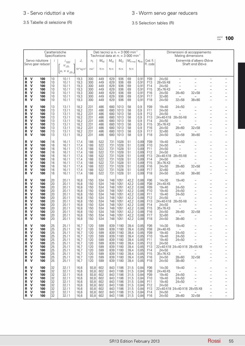
55SR13 Edition February 2013
3 - Servo riduttori a vite 3 - Worm servo gear reducers
CaratteristicheSpecifications
Dati tecnici a n1 = 3 000 min-1
Technical data at n1 = 3 000 min-1Dimensioni di accoppiamento
Mating dimensionsServo riduttore
Servo gear reduceri iesatto - exact J1 n2 MN2 MA2 ME2 MA1max ηvite Cod. fl.
Fl. codeEstremità d’albero Ød×e
Shaft end Ød×e10-4 kg m2 min-1 N m N m N m N m
R V 100 10 10 / 1 19,3 300 449 629 936 69 0,91 F09 24×50 – – – –R V 100 10 10 / 1 19,3 300 449 629 936 69 0,91 F13 28×55-X8 – – – –R V 100 10 10 / 1 19,3 300 449 629 936 69 0,91 F14 24×50 – – – –R V 100 10 10 / 1 19,3 300 449 629 936 69 0,91 F15 35×76-X3 – – – –R V 100 10 10 / 1 19,3 300 449 629 936 69 0,91 F16 24×50 28×60 32×58 – –R V 100 10 10 / 1 19,3 300 449 629 936 69 0,91 F17 32×60 – – – –R V 100 10 10 / 1 19,3 300 449 629 936 69 0,91 F18 24×50 32×58 38×80 – –
R V 100 13 13 / 1 18,2 231 486 680 1013 58 0,9 F09 19×40 24×50 – – –R V 100 13 13 / 1 18,2 231 486 680 1013 58 0,9 F11 24×50 – – – –R V 100 13 13 / 1 18,2 231 486 680 1013 58 0,9 F12 24×50 – – – –R V 100 13 13 / 1 18,2 231 486 680 1013 58 0,9 F13 24×40-X18 28×55-X8 – – –R V 100 13 13 / 1 18,2 231 486 680 1013 58 0,9 F14 24×50 – – – –R V 100 13 13 / 1 18,2 231 486 680 1013 58 0,9 F15 35×76-X3 – – – –R V 100 13 13 / 1 18,2 231 486 680 1013 58 0,9 F16 24×50 28×60 32×58 – –R V 100 13 13 / 1 18,2 231 486 680 1013 58 0,9 F17 32×60 – – – –R V 100 13 13 / 1 18,2 231 486 680 1013 58 0,9 F18 24×50 32×58 38×80 – –
R V 100 16 16 / 1 17,4 188 522 731 1028 51 0,89 F09 19×40 24×50 – – –R V 100 16 16 / 1 17,4 188 522 731 1028 51 0,89 F10 24×50 – – – –R V 100 16 16 / 1 17,4 188 522 731 1028 51 0,89 F11 24×50 – – – –R V 100 16 16 / 1 17,4 188 522 731 1028 51 0,89 F12 24×50 – – – –R V 100 16 16 / 1 17,4 188 522 731 1028 51 0,89 F13 24×40-X18 28×55-X8 – – –R V 100 16 16 / 1 17,4 188 522 731 1028 51 0,89 F14 24×50 – – – –R V 100 16 16 / 1 17,4 188 522 731 1028 51 0,89 F15 35×76-X3 – – – –R V 100 16 16 / 1 17,4 188 522 731 1028 51 0,89 F16 24×50 28×60 32×58 – –R V 100 16 16 / 1 17,4 188 522 731 1028 51 0,89 F17 32×60 – – – –R V 100 16 16 / 1 17,4 188 522 731 1028 51 0,89 F18 24×50 32×58 38×80 – –
R V 100 20 20 / 1 16,8 150 534 748 1051 42,2 0,88 F06 14×30 19×40 – – –R V 100 20 20 / 1 16,8 150 534 748 1051 42,2 0,88 F08 24×40-X5 – – – –R V 100 20 20 / 1 16,8 150 534 748 1051 42,2 0,88 F09 19×40 24×50 – – –R V 100 20 20 / 1 16,8 150 534 748 1051 42,2 0,88 F10 19×40 24×50 – – –R V 100 20 20 / 1 16,8 150 534 748 1051 42,2 0,88 F11 19×40 24×50 – – –R V 100 20 20 / 1 16,8 150 534 748 1051 42,2 0,88 F12 24×50 – – – –R V 100 20 20 / 1 16,8 150 534 748 1051 42,2 0,88 F13 24×40-X18 28×55-X8 – – –R V 100 20 20 / 1 16,8 150 534 748 1051 42,2 0,88 F14 24×50 – – – –R V 100 20 20 / 1 16,8 150 534 748 1051 42,2 0,88 F15 35×76-X3 – – – –R V 100 20 20 / 1 16,8 150 534 748 1051 42,2 0,88 F16 24×50 28×60 32×58 – –R V 100 20 20 / 1 16,8 150 534 748 1051 42,2 0,88 F17 32×60 – – – –R V 100 20 20 / 1 16,8 150 534 748 1051 42,2 0,88 F18 24×50 38×80 – – –
R V 100 25 25 / 1 16,7 120 599 839 1180 39,4 0,85 F06 14×30 19×40 – – –R V 100 25 25 / 1 16,7 120 599 839 1180 39,4 0,85 F08 24×40-X5 – – – –R V 100 25 25 / 1 16,7 120 599 839 1180 39,4 0,85 F09 19×40 24×50 – – –R V 100 25 25 / 1 16,7 120 599 839 1180 39,4 0,85 F10 19×40 24×50 – – –R V 100 25 25 / 1 16,7 120 599 839 1180 39,4 0,85 F11 19×40 24×50 – – –R V 100 25 25 / 1 16,7 120 599 839 1180 39,4 0,85 F12 24×50 – – – –R V 100 25 25 / 1 16,7 120 599 839 1180 39,4 0,85 F13 22×40-X18 24×40-X18 28×55-X8 – –R V 100 25 25 / 1 16,7 120 599 839 1180 39,4 0,85 F14 24×50 – – – –R V 100 25 25 / 1 16,7 120 599 839 1180 39,4 0,85 F15 35×76-X3 – – – –R V 100 25 25 / 1 16,7 120 599 839 1180 39,4 0,85 F16 24×50 28×60 32×58 – –R V 100 25 25 / 1 16,7 120 599 839 1180 39,4 0,85 F18 24×50 38×80 – – –
R V 100 32 32 / 1 16,6 93,8 602 843 1186 31,5 0,84 F06 14×30 19×40 – – –R V 100 32 32 / 1 16,6 93,8 602 843 1186 31,5 0,84 F08 24×40-X5 – – – –R V 100 32 32 / 1 16,6 93,8 602 843 1186 31,5 0,84 F09 19×40 24×50 – – –R V 100 32 32 / 1 16,6 93,8 602 843 1186 31,5 0,84 F10 19×40 24×50 – – –R V 100 32 32 / 1 16,6 93,8 602 843 1186 31,5 0,84 F11 19×40 24×50 – – –R V 100 32 32 / 1 16,6 93,8 602 843 1186 31,5 0,84 F12 24×50 – – – –R V 100 32 32 / 1 16,6 93,8 602 843 1186 31,5 0,84 F13 22×40-X18 24×40-X18 28×55-X8 – –R V 100 32 32 / 1 16,6 93,8 602 843 1186 31,5 0,84 F14 24×50 – – – –R V 100 32 32 / 1 16,6 93,8 602 843 1186 31,5 0,84 F16 24×50 28×60 32×58 – –
3.5 Tabelle di selezione (R) 3.5 Selection tables (R)
grand. size 100
i esatto
u
u1 × u
viteworm
viteworm
[ ]i esatto
exact
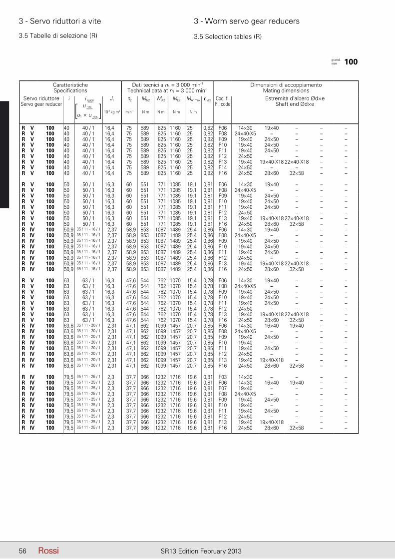
56 SR13 Edition February 2013
3 - Servo riduttori a vite 3 - Worm servo gear reducers
3.5 Tabelle di selezione (R) 3.5 Selection tables (R)
CaratteristicheSpecifications
Dati tecnici a n1 = 3 000 min-1
Technical data at n1 = 3 000 min-1Dimensioni di accoppiamento
Mating dimensionsServo riduttore
Servo gear reduceri iesatto - exact J1 n2 MN2 MA2 ME2 MA1max ηvite Cod. fl.
Fl. codeEstremità d’albero Ød×e
Shaft end Ød×e10-4 kg m2 min-1 N m N m N m N m
R V 100 40 40 / 1 16,4 75 589 825 1160 25 0,82 F06 14×30 19×40 – – –R V 100 40 40 / 1 16,4 75 589 825 1160 25 0,82 F08 24×40-X5 – – – –R V 100 40 40 / 1 16,4 75 589 825 1160 25 0,82 F09 19×40 24×50 – – –R V 100 40 40 / 1 16,4 75 589 825 1160 25 0,82 F10 19×40 24×50 – – –R V 100 40 40 / 1 16,4 75 589 825 1160 25 0,82 F11 19×40 24×50 – – –R V 100 40 40 / 1 16,4 75 589 825 1160 25 0,82 F12 24×50 – – – –R V 100 40 40 / 1 16,4 75 589 825 1160 25 0,82 F13 19×40 19×40-X18 22×40-X18 – –R V 100 40 40 / 1 16,4 75 589 825 1160 25 0,82 F14 24×50 – – – –R V 100 40 40 / 1 16,4 75 589 825 1160 25 0,82 F16 24×50 28×60 32×58 – –
R V 100 50 50 / 1 16,3 60 551 771 1085 19,1 0,81 F06 14×30 19×40 – – –R V 100 50 50 / 1 16,3 60 551 771 1085 19,1 0,81 F08 24×40-X5 – – – –R V 100 50 50 / 1 16,3 60 551 771 1085 19,1 0,81 F09 19×40 24×50 – – –R V 100 50 50 / 1 16,3 60 551 771 1085 19,1 0,81 F10 19×40 24×50 – – –R V 100 50 50 / 1 16,3 60 551 771 1085 19,1 0,81 F11 19×40 24×50 – – –R V 100 50 50 / 1 16,3 60 551 771 1085 19,1 0,81 F12 24×50 – – – –R V 100 50 50 / 1 16,3 60 551 771 1085 19,1 0,81 F13 19×40 19×40-X18 22×40-X18 – –R V 100 50 50 / 1 16,3 60 551 771 1085 19,1 0,81 F16 24×50 28×60 32×58 – –R IV 100 50,9 35 / 11 - 16 / 1 2,37 58,9 853 1087 1489 25,4 0,86 F06 14×30 19×40 – – –R IV 100 50,9 35 / 11 - 16 / 1 2,37 58,9 853 1087 1489 25,4 0,86 F08 24×40-X5 – – – –R IV 100 50,9 35 / 11 - 16 / 1 2,37 58,9 853 1087 1489 25,4 0,86 F09 19×40 24×50 – – –R IV 100 50,9 35 / 11 - 16 / 1 2,37 58,9 853 1087 1489 25,4 0,86 F10 19×40 24×50 – – –R IV 100 50,9 35 / 11 - 16 / 1 2,37 58,9 853 1087 1489 25,4 0,86 F11 19×40 24×50 – – –R IV 100 50,9 35 / 11 - 16 / 1 2,37 58,9 853 1087 1489 25,4 0,86 F12 24×50 – – – –R IV 100 50,9 35 / 11 - 16 / 1 2,37 58,9 853 1087 1489 25,4 0,86 F13 19×40 19×40-X18 22×40-X18 – –R IV 100 50,9 35 / 11 - 16 / 1 2,37 58,9 853 1087 1489 25,4 0,86 F16 24×50 28×60 32×58 – –
R V 100 63 63 / 1 16,3 47,6 544 762 1070 15,4 0,78 F06 14×30 19×40 – – –R V 100 63 63 / 1 16,3 47,6 544 762 1070 15,4 0,78 F08 24×40-X5 – – – –R V 100 63 63 / 1 16,3 47,6 544 762 1070 15,4 0,78 F09 19×40 24×50 – – –R V 100 63 63 / 1 16,3 47,6 544 762 1070 15,4 0,78 F10 19×40 24×50 – – –R V 100 63 63 / 1 16,3 47,6 544 762 1070 15,4 0,78 F11 19×40 24×50 – – –R V 100 63 63 / 1 16,3 47,6 544 762 1070 15,4 0,78 F12 24×50 – – – –R V 100 63 63 / 1 16,3 47,6 544 762 1070 15,4 0,78 F13 19×40 19×40-X18 22×40-X18 – –R V 100 63 63 / 1 16,3 47,6 544 762 1070 15,4 0,78 F16 24×50 28×60 32×58 – –R IV 100 63,6 35 / 11 - 20 / 1 2,31 47,1 862 1099 1457 20,7 0,85 F06 14×30 16×40 19×40 – –R IV 100 63,6 35 / 11 - 20 / 1 2,31 47,1 862 1099 1457 20,7 0,85 F08 24×40-X5 – – – –R IV 100 63,6 35 / 11 - 20 / 1 2,31 47,1 862 1099 1457 20,7 0,85 F09 19×40 24×50 – – –R IV 100 63,6 35 / 11 - 20 / 1 2,31 47,1 862 1099 1457 20,7 0,85 F10 19×40 – – – –R IV 100 63,6 35 / 11 - 20 / 1 2,31 47,1 862 1099 1457 20,7 0,85 F11 19×40 24×50 – – –R IV 100 63,6 35 / 11 - 20 / 1 2,31 47,1 862 1099 1457 20,7 0,85 F12 24×50 – – – –R IV 100 63,6 35 / 11 - 20 / 1 2,31 47,1 862 1099 1457 20,7 0,85 F13 19×40 19×40-X18 – – –R IV 100 63,6 35 / 11 - 20 / 1 2,31 47,1 862 1099 1457 20,7 0,85 F16 24×50 28×60 32×58 – –
R IV 100 79,5 35 / 11 - 25 / 1 2,3 37,7 966 1232 1716 19,6 0,81 F03 14×30 – – – –R IV 100 79,5 35 / 11 - 25 / 1 2,3 37,7 966 1232 1716 19,6 0,81 F06 14×30 16×40 19×40 – –R IV 100 79,5 35 / 11 - 25 / 1 2,3 37,7 966 1232 1716 19,6 0,81 F07 19×40 – – – –R IV 100 79,5 35 / 11 - 25 / 1 2,3 37,7 966 1232 1716 19,6 0,81 F08 24×40-X5 – – – –R IV 100 79,5 35 / 11 - 25 / 1 2,3 37,7 966 1232 1716 19,6 0,81 F09 19×40 24×50 – – –R IV 100 79,5 35 / 11 - 25 / 1 2,3 37,7 966 1232 1716 19,6 0,81 F10 19×40 – – – –R IV 100 79,5 35 / 11 - 25 / 1 2,3 37,7 966 1232 1716 19,6 0,81 F11 19×40 24×50 – – –R IV 100 79,5 35 / 11 - 25 / 1 2,3 37,7 966 1232 1716 19,6 0,81 F12 24×50 – – – –R IV 100 79,5 35 / 11 - 25 / 1 2,3 37,7 966 1232 1716 19,6 0,81 F13 19×40 19×40-X18 – – –R IV 100 79,5 35 / 11 - 25 / 1 2,3 37,7 966 1232 1716 19,6 0,81 F16 24×50 28×60 32×58 – –
grand. size 100
i esatto
u
u1 × u
viteworm
viteworm
[ ]i esatto
exact

57SR13 Edition February 2013
3 - Servo riduttori a vite 3 - Worm servo gear reducers
3.5 Tabelle di selezione (R) 3.5 Selection tables (R)
CaratteristicheSpecifications
Dati tecnici a n1 = 3 000 min-1
Technical data at n1 = 3 000 min-1Dimensioni di accoppiamento
Mating dimensionsServo riduttore
Servo gear reduceri iesatto - exact J1 n2 MN2 MA2 ME2 MA1max ηvite Cod. fl.
Fl. codeEstremità d’albero Ød×e
Shaft end Ød×e10-4 kg m2 min-1 N m N m N m N m
R IV 100 102 35 / 11 - 32 / 1 2,29 29,5 944 1203 1602 15,4 0,78 F02 14×30 – – – –R IV 100 102 35 / 11 - 32 / 1 2,29 29,5 944 1203 1602 15,4 0,78 F03 14×30 – – – –R IV 100 102 35 / 11 - 32 / 1 2,29 29,5 944 1203 1602 15,4 0,78 F05 19×40 – – – –R IV 100 102 35 / 11 - 32 / 1 2,29 29,5 944 1203 1602 15,4 0,78 F06 14×30 16×40 19×40 – –R IV 100 102 35 / 11 - 32 / 1 2,29 29,5 944 1203 1602 15,4 0,78 F07 19×40 – – – –R IV 100 102 35 / 11 - 32 / 1 2,29 29,5 944 1203 1602 15,4 0,78 F08 24×40-X5 – – – –R IV 100 102 35 / 11 - 32 / 1 2,29 29,5 944 1203 1602 15,4 0,78 F09 19×40 24×50 – – –R IV 100 102 35 / 11 - 32 / 1 2,29 29,5 944 1203 1602 15,4 0,78 F10 19×40 – – – –R IV 100 102 35 / 11 - 32 / 1 2,29 29,5 944 1203 1602 15,4 0,78 F11 19×40 24×50 – – –R IV 100 102 35 / 11 - 32 / 1 2,29 29,5 944 1203 1602 15,4 0,78 F12 24×50 – – – –R IV 100 102 35 / 11 - 32 / 1 2,29 29,5 944 1203 1602 15,4 0,78 F13 19×40 19×40-X18 – – –R IV 100 102 35 / 11 - 32 / 1 2,29 29,5 944 1203 1602 15,4 0,78 F16 24×50 28×60 32×58 – –
R IV 100 127 35 / 11 - 40 / 1 2,27 23,6 898 1145 1514 12 0,77 F02 14×30 – – – –R IV 100 127 35 / 11 - 40 / 1 2,27 23,6 898 1145 1514 12 0,77 F03 14×30 – – – –R IV 100 127 35 / 11 - 40 / 1 2,27 23,6 898 1145 1514 12 0,77 F05 16×40 19×40 – – –R IV 100 127 35 / 11 - 40 / 1 2,27 23,6 898 1145 1514 12 0,77 F06 14×30 16×40 19×40 – –R IV 100 127 35 / 11 - 40 / 1 2,27 23,6 898 1145 1514 12 0,77 F07 19×40 – – – –R IV 100 127 35 / 11 - 40 / 1 2,27 23,6 898 1145 1514 12 0,77 F08 24×40-X5 – – – –R IV 100 127 35 / 11 - 40 / 1 2,27 23,6 898 1145 1514 12 0,77 F09 19×40 – – – –R IV 100 127 35 / 11 - 40 / 1 2,27 23,6 898 1145 1514 12 0,77 F10 19×40 – – – –R IV 100 127 35 / 11 - 40 / 1 2,27 23,6 898 1145 1514 12 0,77 F11 19×40 24×50 – – –R IV 100 127 35 / 11 - 40 / 1 2,27 23,6 898 1145 1514 12 0,77 F12 24×50 – – – –R IV 100 127 35 / 11 - 40 / 1 2,27 23,6 898 1145 1514 12 0,77 F13 19×40 19×40-X18 – – –R IV 100 127 35 / 11 - 40 / 1 2,27 23,6 898 1145 1514 12 0,77 F16 24×50 28×60 – – –
grand. size 100
i esatto
u
u1 × u
viteworm
viteworm
[ ]i esatto
exact
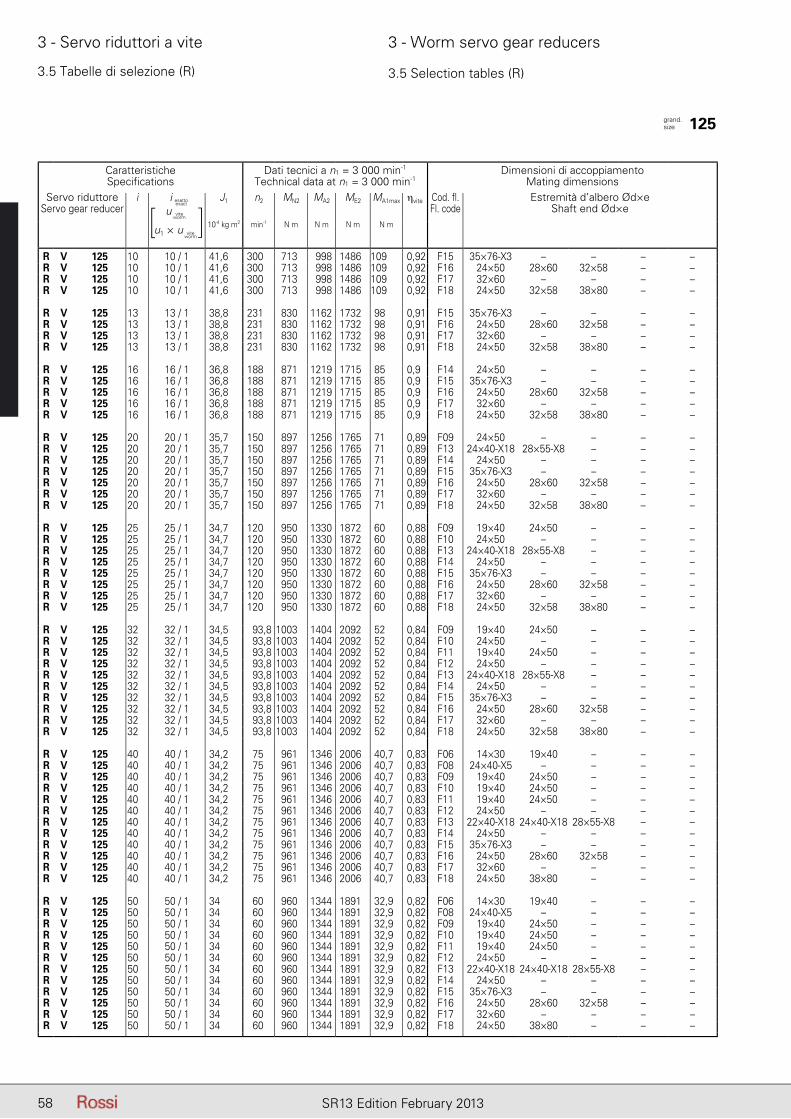
58 SR13 Edition February 2013
3 - Servo riduttori a vite 3 - Worm servo gear reducers
3.5 Tabelle di selezione (R) 3.5 Selection tables (R)
CaratteristicheSpecifications
Dati tecnici a n1 = 3 000 min-1
Technical data at n1 = 3 000 min-1Dimensioni di accoppiamento
Mating dimensionsServo riduttore
Servo gear reduceri iesatto - exact J1 n2 MN2 MA2 ME2 MA1max ηvite Cod. fl.
Fl. codeEstremità d’albero Ød×e
Shaft end Ød×e10-4 kg m2 min-1 N m N m N m N m
R V 125 10 10 / 1 41,6 300 713 998 1486 109 0,92 F15 35×76-X3 – – – –R V 125 10 10 / 1 41,6 300 713 998 1486 109 0,92 F16 24×50 28×60 32×58 – –R V 125 10 10 / 1 41,6 300 713 998 1486 109 0,92 F17 32×60 – – – –R V 125 10 10 / 1 41,6 300 713 998 1486 109 0,92 F18 24×50 32×58 38×80 – –
R V 125 13 13 / 1 38,8 231 830 1162 1732 98 0,91 F15 35×76-X3 – – – –R V 125 13 13 / 1 38,8 231 830 1162 1732 98 0,91 F16 24×50 28×60 32×58 – –R V 125 13 13 / 1 38,8 231 830 1162 1732 98 0,91 F17 32×60 – – – –R V 125 13 13 / 1 38,8 231 830 1162 1732 98 0,91 F18 24×50 32×58 38×80 – –
R V 125 16 16 / 1 36,8 188 871 1219 1715 85 0,9 F14 24×50 – – – –R V 125 16 16 / 1 36,8 188 871 1219 1715 85 0,9 F15 35×76-X3 – – – –R V 125 16 16 / 1 36,8 188 871 1219 1715 85 0,9 F16 24×50 28×60 32×58 – –R V 125 16 16 / 1 36,8 188 871 1219 1715 85 0,9 F17 32×60 – – – –R V 125 16 16 / 1 36,8 188 871 1219 1715 85 0,9 F18 24×50 32×58 38×80 – –
R V 125 20 20 / 1 35,7 150 897 1256 1765 71 0,89 F09 24×50 – – – –R V 125 20 20 / 1 35,7 150 897 1256 1765 71 0,89 F13 24×40-X18 28×55-X8 – – –R V 125 20 20 / 1 35,7 150 897 1256 1765 71 0,89 F14 24×50 – – – –R V 125 20 20 / 1 35,7 150 897 1256 1765 71 0,89 F15 35×76-X3 – – – –R V 125 20 20 / 1 35,7 150 897 1256 1765 71 0,89 F16 24×50 28×60 32×58 – –R V 125 20 20 / 1 35,7 150 897 1256 1765 71 0,89 F17 32×60 – – – –R V 125 20 20 / 1 35,7 150 897 1256 1765 71 0,89 F18 24×50 32×58 38×80 – –
R V 125 25 25 / 1 34,7 120 950 1330 1872 60 0,88 F09 19×40 24×50 – – –R V 125 25 25 / 1 34,7 120 950 1330 1872 60 0,88 F10 24×50 – – – –R V 125 25 25 / 1 34,7 120 950 1330 1872 60 0,88 F13 24×40-X18 28×55-X8 – – –R V 125 25 25 / 1 34,7 120 950 1330 1872 60 0,88 F14 24×50 – – – –R V 125 25 25 / 1 34,7 120 950 1330 1872 60 0,88 F15 35×76-X3 – – – –R V 125 25 25 / 1 34,7 120 950 1330 1872 60 0,88 F16 24×50 28×60 32×58 – –R V 125 25 25 / 1 34,7 120 950 1330 1872 60 0,88 F17 32×60 – – – –R V 125 25 25 / 1 34,7 120 950 1330 1872 60 0,88 F18 24×50 32×58 38×80 – –
R V 125 32 32 / 1 34,5 93,8 1003 1404 2092 52 0,84 F09 19×40 24×50 – – –R V 125 32 32 / 1 34,5 93,8 1003 1404 2092 52 0,84 F10 24×50 – – – –R V 125 32 32 / 1 34,5 93,8 1003 1404 2092 52 0,84 F11 19×40 24×50 – – –R V 125 32 32 / 1 34,5 93,8 1003 1404 2092 52 0,84 F12 24×50 – – – –R V 125 32 32 / 1 34,5 93,8 1003 1404 2092 52 0,84 F13 24×40-X18 28×55-X8 – – –R V 125 32 32 / 1 34,5 93,8 1003 1404 2092 52 0,84 F14 24×50 – – – –R V 125 32 32 / 1 34,5 93,8 1003 1404 2092 52 0,84 F15 35×76-X3 – – – –R V 125 32 32 / 1 34,5 93,8 1003 1404 2092 52 0,84 F16 24×50 28×60 32×58 – –R V 125 32 32 / 1 34,5 93,8 1003 1404 2092 52 0,84 F17 32×60 – – – –R V 125 32 32 / 1 34,5 93,8 1003 1404 2092 52 0,84 F18 24×50 32×58 38×80 – –
R V 125 40 40 / 1 34,2 75 961 1346 2006 40,7 0,83 F06 14×30 19×40 – – –R V 125 40 40 / 1 34,2 75 961 1346 2006 40,7 0,83 F08 24×40-X5 – – – –R V 125 40 40 / 1 34,2 75 961 1346 2006 40,7 0,83 F09 19×40 24×50 – – –R V 125 40 40 / 1 34,2 75 961 1346 2006 40,7 0,83 F10 19×40 24×50 – – –R V 125 40 40 / 1 34,2 75 961 1346 2006 40,7 0,83 F11 19×40 24×50 – – –R V 125 40 40 / 1 34,2 75 961 1346 2006 40,7 0,83 F12 24×50 – – – –R V 125 40 40 / 1 34,2 75 961 1346 2006 40,7 0,83 F13 22×40-X18 24×40-X18 28×55-X8 – –R V 125 40 40 / 1 34,2 75 961 1346 2006 40,7 0,83 F14 24×50 – – – –R V 125 40 40 / 1 34,2 75 961 1346 2006 40,7 0,83 F15 35×76-X3 – – – –R V 125 40 40 / 1 34,2 75 961 1346 2006 40,7 0,83 F16 24×50 28×60 32×58 – –R V 125 40 40 / 1 34,2 75 961 1346 2006 40,7 0,83 F17 32×60 – – – –R V 125 40 40 / 1 34,2 75 961 1346 2006 40,7 0,83 F18 24×50 38×80 – – –
R V 125 50 50 / 1 34 60 960 1344 1891 32,9 0,82 F06 14×30 19×40 – – –R V 125 50 50 / 1 34 60 960 1344 1891 32,9 0,82 F08 24×40-X5 – – – –R V 125 50 50 / 1 34 60 960 1344 1891 32,9 0,82 F09 19×40 24×50 – – –R V 125 50 50 / 1 34 60 960 1344 1891 32,9 0,82 F10 19×40 24×50 – – –R V 125 50 50 / 1 34 60 960 1344 1891 32,9 0,82 F11 19×40 24×50 – – –R V 125 50 50 / 1 34 60 960 1344 1891 32,9 0,82 F12 24×50 – – – –R V 125 50 50 / 1 34 60 960 1344 1891 32,9 0,82 F13 22×40-X18 24×40-X18 28×55-X8 – –R V 125 50 50 / 1 34 60 960 1344 1891 32,9 0,82 F14 24×50 – – – –R V 125 50 50 / 1 34 60 960 1344 1891 32,9 0,82 F15 35×76-X3 – – – –R V 125 50 50 / 1 34 60 960 1344 1891 32,9 0,82 F16 24×50 28×60 32×58 – –R V 125 50 50 / 1 34 60 960 1344 1891 32,9 0,82 F17 32×60 – – – –R V 125 50 50 / 1 34 60 960 1344 1891 32,9 0,82 F18 24×50 38×80 – – –
grand. size 125
i esatto
u
u1 × u
viteworm
viteworm
[ ]i esatto
exact
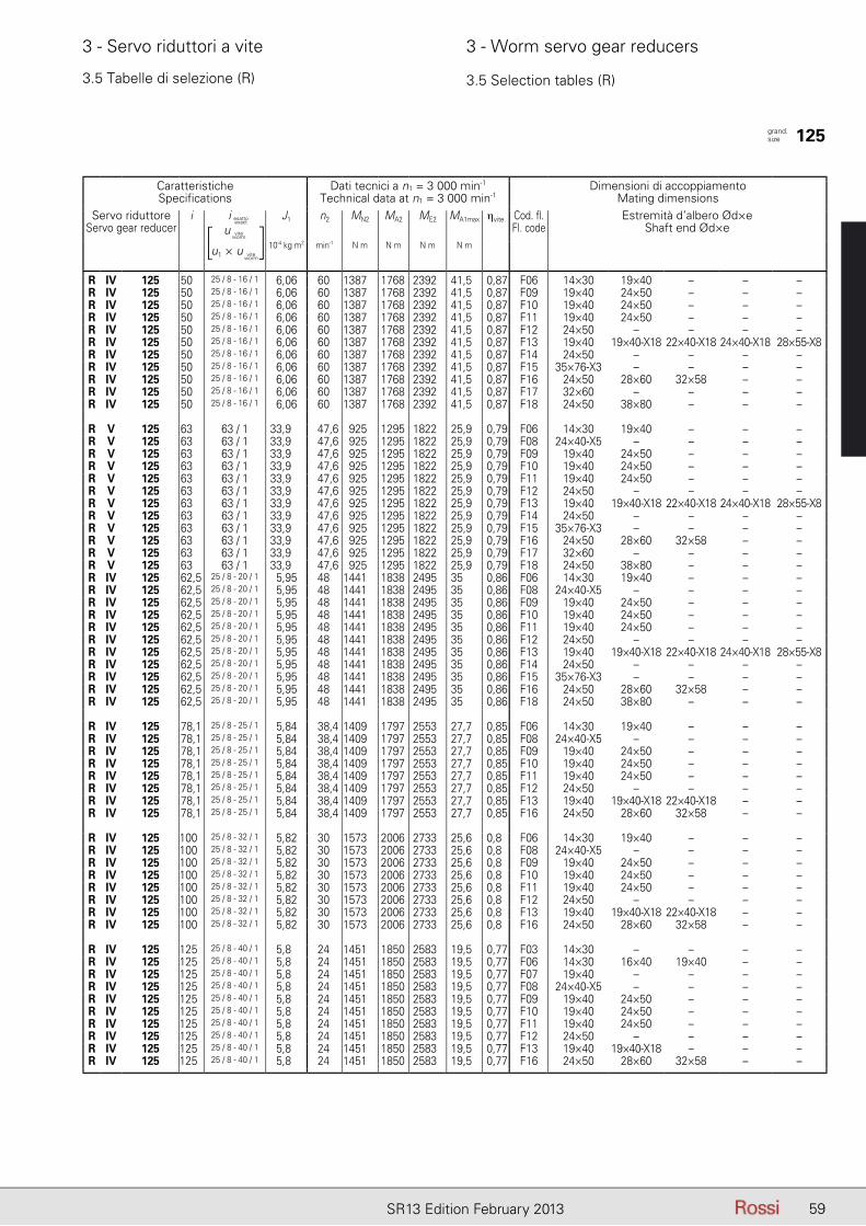
59SR13 Edition February 2013
3 - Servo riduttori a vite 3 - Worm servo gear reducers
3.5 Tabelle di selezione (R) 3.5 Selection tables (R)
CaratteristicheSpecifications
Dati tecnici a n1 = 3 000 min-1
Technical data at n1 = 3 000 min-1Dimensioni di accoppiamento
Mating dimensionsServo riduttore
Servo gear reduceri iesatto - exact J1 n2 MN2 MA2 ME2 MA1max ηvite Cod. fl.
Fl. codeEstremità d’albero Ød×e
Shaft end Ød×e10-4 kg m2 min-1 N m N m N m N m
R IV 125 50 25 / 8 - 16 / 1 6,06 60 1387 1768 2392 41,5 0,87 F06 14×30 19×40 – – –R IV 125 50 25 / 8 - 16 / 1 6,06 60 1387 1768 2392 41,5 0,87 F09 19×40 24×50 – – –R IV 125 50 25 / 8 - 16 / 1 6,06 60 1387 1768 2392 41,5 0,87 F10 19×40 24×50 – – –R IV 125 50 25 / 8 - 16 / 1 6,06 60 1387 1768 2392 41,5 0,87 F11 19×40 24×50 – – –R IV 125 50 25 / 8 - 16 / 1 6,06 60 1387 1768 2392 41,5 0,87 F12 24×50 – – – –R IV 125 50 25 / 8 - 16 / 1 6,06 60 1387 1768 2392 41,5 0,87 F13 19×40 19×40-X18 22×40-X18 24×40-X18 28×55-X8R IV 125 50 25 / 8 - 16 / 1 6,06 60 1387 1768 2392 41,5 0,87 F14 24×50 – – – –R IV 125 50 25 / 8 - 16 / 1 6,06 60 1387 1768 2392 41,5 0,87 F15 35×76-X3 – – – –R IV 125 50 25 / 8 - 16 / 1 6,06 60 1387 1768 2392 41,5 0,87 F16 24×50 28×60 32×58 – –R IV 125 50 25 / 8 - 16 / 1 6,06 60 1387 1768 2392 41,5 0,87 F17 32×60 – – – –R IV 125 50 25 / 8 - 16 / 1 6,06 60 1387 1768 2392 41,5 0,87 F18 24×50 38×80 – – –
R V 125 63 63 / 1 33,9 47,6 925 1295 1822 25,9 0,79 F06 14×30 19×40 – – –R V 125 63 63 / 1 33,9 47,6 925 1295 1822 25,9 0,79 F08 24×40-X5 – – – –R V 125 63 63 / 1 33,9 47,6 925 1295 1822 25,9 0,79 F09 19×40 24×50 – – –R V 125 63 63 / 1 33,9 47,6 925 1295 1822 25,9 0,79 F10 19×40 24×50 – – –R V 125 63 63 / 1 33,9 47,6 925 1295 1822 25,9 0,79 F11 19×40 24×50 – – –R V 125 63 63 / 1 33,9 47,6 925 1295 1822 25,9 0,79 F12 24×50 – – – –R V 125 63 63 / 1 33,9 47,6 925 1295 1822 25,9 0,79 F13 19×40 19×40-X18 22×40-X18 24×40-X18 28×55-X8R V 125 63 63 / 1 33,9 47,6 925 1295 1822 25,9 0,79 F14 24×50 – – – –R V 125 63 63 / 1 33,9 47,6 925 1295 1822 25,9 0,79 F15 35×76-X3 – – – –R V 125 63 63 / 1 33,9 47,6 925 1295 1822 25,9 0,79 F16 24×50 28×60 32×58 – –R V 125 63 63 / 1 33,9 47,6 925 1295 1822 25,9 0,79 F17 32×60 – – – –R V 125 63 63 / 1 33,9 47,6 925 1295 1822 25,9 0,79 F18 24×50 38×80 – – –R IV 125 62,5 25 / 8 - 20 / 1 5,95 48 1441 1838 2495 35 0,86 F06 14×30 19×40 – – –R IV 125 62,5 25 / 8 - 20 / 1 5,95 48 1441 1838 2495 35 0,86 F08 24×40-X5 – – – –R IV 125 62,5 25 / 8 - 20 / 1 5,95 48 1441 1838 2495 35 0,86 F09 19×40 24×50 – – –R IV 125 62,5 25 / 8 - 20 / 1 5,95 48 1441 1838 2495 35 0,86 F10 19×40 24×50 – – –R IV 125 62,5 25 / 8 - 20 / 1 5,95 48 1441 1838 2495 35 0,86 F11 19×40 24×50 – – –R IV 125 62,5 25 / 8 - 20 / 1 5,95 48 1441 1838 2495 35 0,86 F12 24×50 – – – –R IV 125 62,5 25 / 8 - 20 / 1 5,95 48 1441 1838 2495 35 0,86 F13 19×40 19×40-X18 22×40-X18 24×40-X18 28×55-X8R IV 125 62,5 25 / 8 - 20 / 1 5,95 48 1441 1838 2495 35 0,86 F14 24×50 – – – –R IV 125 62,5 25 / 8 - 20 / 1 5,95 48 1441 1838 2495 35 0,86 F15 35×76-X3 – – – –R IV 125 62,5 25 / 8 - 20 / 1 5,95 48 1441 1838 2495 35 0,86 F16 24×50 28×60 32×58 – –R IV 125 62,5 25 / 8 - 20 / 1 5,95 48 1441 1838 2495 35 0,86 F18 24×50 38×80 – – –
R IV 125 78,1 25 / 8 - 25 / 1 5,84 38,4 1409 1797 2553 27,7 0,85 F06 14×30 19×40 – – –R IV 125 78,1 25 / 8 - 25 / 1 5,84 38,4 1409 1797 2553 27,7 0,85 F08 24×40-X5 – – – –R IV 125 78,1 25 / 8 - 25 / 1 5,84 38,4 1409 1797 2553 27,7 0,85 F09 19×40 24×50 – – –R IV 125 78,1 25 / 8 - 25 / 1 5,84 38,4 1409 1797 2553 27,7 0,85 F10 19×40 24×50 – – –R IV 125 78,1 25 / 8 - 25 / 1 5,84 38,4 1409 1797 2553 27,7 0,85 F11 19×40 24×50 – – –R IV 125 78,1 25 / 8 - 25 / 1 5,84 38,4 1409 1797 2553 27,7 0,85 F12 24×50 – – – –R IV 125 78,1 25 / 8 - 25 / 1 5,84 38,4 1409 1797 2553 27,7 0,85 F13 19×40 19×40-X18 22×40-X18 – –R IV 125 78,1 25 / 8 - 25 / 1 5,84 38,4 1409 1797 2553 27,7 0,85 F16 24×50 28×60 32×58 – –
R IV 125 100 25 / 8 - 32 / 1 5,82 30 1573 2006 2733 25,6 0,8 F06 14×30 19×40 – – –R IV 125 100 25 / 8 - 32 / 1 5,82 30 1573 2006 2733 25,6 0,8 F08 24×40-X5 – – – –R IV 125 100 25 / 8 - 32 / 1 5,82 30 1573 2006 2733 25,6 0,8 F09 19×40 24×50 – – –R IV 125 100 25 / 8 - 32 / 1 5,82 30 1573 2006 2733 25,6 0,8 F10 19×40 24×50 – – –R IV 125 100 25 / 8 - 32 / 1 5,82 30 1573 2006 2733 25,6 0,8 F11 19×40 24×50 – – –R IV 125 100 25 / 8 - 32 / 1 5,82 30 1573 2006 2733 25,6 0,8 F12 24×50 – – – –R IV 125 100 25 / 8 - 32 / 1 5,82 30 1573 2006 2733 25,6 0,8 F13 19×40 19×40-X18 22×40-X18 – –R IV 125 100 25 / 8 - 32 / 1 5,82 30 1573 2006 2733 25,6 0,8 F16 24×50 28×60 32×58 – –
R IV 125 125 25 / 8 - 40 / 1 5,8 24 1451 1850 2583 19,5 0,77 F03 14×30 – – – –R IV 125 125 25 / 8 - 40 / 1 5,8 24 1451 1850 2583 19,5 0,77 F06 14×30 16×40 19×40 – –R IV 125 125 25 / 8 - 40 / 1 5,8 24 1451 1850 2583 19,5 0,77 F07 19×40 – – – –R IV 125 125 25 / 8 - 40 / 1 5,8 24 1451 1850 2583 19,5 0,77 F08 24×40-X5 – – – –R IV 125 125 25 / 8 - 40 / 1 5,8 24 1451 1850 2583 19,5 0,77 F09 19×40 24×50 – – –R IV 125 125 25 / 8 - 40 / 1 5,8 24 1451 1850 2583 19,5 0,77 F10 19×40 24×50 – – –R IV 125 125 25 / 8 - 40 / 1 5,8 24 1451 1850 2583 19,5 0,77 F11 19×40 24×50 – – –R IV 125 125 25 / 8 - 40 / 1 5,8 24 1451 1850 2583 19,5 0,77 F12 24×50 – – – –R IV 125 125 25 / 8 - 40 / 1 5,8 24 1451 1850 2583 19,5 0,77 F13 19×40 19×40-X18 – – –R IV 125 125 25 / 8 - 40 / 1 5,8 24 1451 1850 2583 19,5 0,77 F16 24×50 28×60 32×58 – –
grand. size 125
i esatto
u
u1 × u
viteworm
viteworm
[ ]i esatto
exact
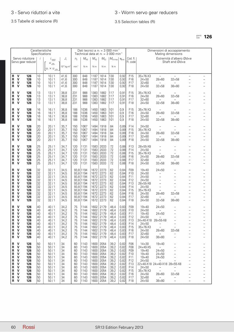
60 SR13 Edition February 2013
3 - Servo riduttori a vite 3 - Worm servo gear reducers
3.5 Tabelle di selezione (R) 3.5 Selection tables (R)
CaratteristicheSpecifications
Dati tecnici a n1 = 3 000 min-1
Technical data at n1 = 3 000 min-1Dimensioni di accoppiamento
Mating dimensionsServo riduttore
Servo gear reduceri iesatto - exact J1 n2 MN2 MA2 ME2 MA1max ηvite Cod. fl.
Fl. codeEstremità d’albero Ød×e
Shaft end Ød×e10-4 kg m2 min-1 N m N m N m N m
R V 126 10 10 / 1 41,6 300 848 1187 1614 130 0,92 F15 35×76-X3 – – – –R V 126 10 10 / 1 41,6 300 848 1187 1614 130 0,92 F16 24×50 28×60 32×58 – –R V 126 10 10 / 1 41,6 300 848 1187 1614 130 0,92 F17 32×60 – – – –R V 126 10 10 / 1 41,6 300 848 1187 1614 130 0,92 F18 24×50 32×58 38×80 – –
R V 126 13 13 / 1 38,8 231 988 1383 1882 117 0,91 F15 35×76-X3 – – – –R V 126 13 13 / 1 38,8 231 988 1383 1882 117 0,91 F16 24×50 28×60 32×58 – –R V 126 13 13 / 1 38,8 231 988 1383 1882 117 0,91 F17 32×60 – – – –R V 126 13 13 / 1 38,8 231 988 1383 1882 117 0,91 F18 24×50 32×58 38×80 – –
R V 126 16 16 / 1 36,8 188 1036 1450 1863 101 0,9 F15 35×76-X3 – – – –R V 126 16 16 / 1 36,8 188 1036 1450 1863 101 0,9 F16 24×50 28×60 32×58 – –R V 126 16 16 / 1 36,8 188 1036 1450 1863 101 0,9 F17 32×60 – – – –R V 126 16 16 / 1 36,8 188 1036 1450 1863 101 0,9 F18 24×50 32×58 38×80 – –
R V 126 20 20 / 1 35,7 150 1067 1494 1918 84 0,89 F14 24×50 – – – –R V 126 20 20 / 1 35,7 150 1067 1494 1918 84 0,89 F15 35×76-X3 – – – –R V 126 20 20 / 1 35,7 150 1067 1494 1918 84 0,89 F16 24×50 28×60 32×58 – –R V 126 20 20 / 1 35,7 150 1067 1494 1918 84 0,89 F17 32×60 – – – –R V 126 20 20 / 1 35,7 150 1067 1494 1918 84 0,89 F18 24×50 32×58 38×80 – –
R V 126 25 25 / 1 34,7 120 1131 1583 2033 72 0,88 F13 28×55-X8 – – – –R V 126 25 25 / 1 34,7 120 1131 1583 2033 72 0,88 F14 24×50 – – – –R V 126 25 25 / 1 34,7 120 1131 1583 2033 72 0,88 F15 35×76-X3 – – – –R V 126 25 25 / 1 34,7 120 1131 1583 2033 72 0,88 F16 24×50 28×60 32×58 – –R V 126 25 25 / 1 34,7 120 1131 1583 2033 72 0,88 F17 32×60 – – – –R V 126 25 25 / 1 34,7 120 1131 1583 2033 72 0,88 F18 24×50 32×58 38×80 – –
R V 126 32 32 / 1 34,5 93,8 1194 1672 2273 62 0,84 F09 19×40 24×50 – – –R V 126 32 32 / 1 34,5 93,8 1194 1672 2273 62 0,84 F10 24×50 – – – –R V 126 32 32 / 1 34,5 93,8 1194 1672 2273 62 0,84 F11 24×50 – – – –R V 126 32 32 / 1 34,5 93,8 1194 1672 2273 62 0,84 F12 24×50 – – – –R V 126 32 32 / 1 34,5 93,8 1194 1672 2273 62 0,84 F13 28×55-X8 – – – –R V 126 32 32 / 1 34,5 93,8 1194 1672 2273 62 0,84 F14 24×50 – – – –R V 126 32 32 / 1 34,5 93,8 1194 1672 2273 62 0,84 F15 35×76-X3 – – – –R V 126 32 32 / 1 34,5 93,8 1194 1672 2273 62 0,84 F16 24×50 28×60 32×58 – –R V 126 32 32 / 1 34,5 93,8 1194 1672 2273 62 0,84 F17 32×60 – – – –R V 126 32 32 / 1 34,5 93,8 1194 1672 2273 62 0,84 F18 24×50 32×58 38×80 – –
R V 126 40 40 / 1 34,2 75 1144 1602 2179 48,4 0,83 F09 19×40 24×50 – – –R V 126 40 40 / 1 34,2 75 1144 1602 2179 48,4 0,83 F10 24×50 – – – –R V 126 40 40 / 1 34,2 75 1144 1602 2179 48,4 0,83 F11 19×40 24×50 – – –R V 126 40 40 / 1 34,2 75 1144 1602 2179 48,4 0,83 F12 24×50 – – – –R V 126 40 40 / 1 34,2 75 1144 1602 2179 48,4 0,83 F13 24×40-X18 28×55-X8 – – –R V 126 40 40 / 1 34,2 75 1144 1602 2179 48,4 0,83 F14 24×50 – – – –R V 126 40 40 / 1 34,2 75 1144 1602 2179 48,4 0,83 F15 35×76-X3 – – – –R V 126 40 40 / 1 34,2 75 1144 1602 2179 48,4 0,83 F16 24×50 28×60 32×58 – –R V 126 40 40 / 1 34,2 75 1144 1602 2179 48,4 0,83 F17 32×60 – – – –R V 126 40 40 / 1 34,2 75 1144 1602 2179 48,4 0,83 F18 24×50 38×80 – – –
R V 126 50 50 / 1 34 60 1143 1600 2054 39,2 0,82 F06 14×30 19×40 – – –R V 126 50 50 / 1 34 60 1143 1600 2054 39,2 0,82 F08 24×40-X5 – – – –R V 126 50 50 / 1 34 60 1143 1600 2054 39,2 0,82 F09 19×40 24×50 – – –R V 126 50 50 / 1 34 60 1143 1600 2054 39,2 0,82 F10 19×40 24×50 – – –R V 126 50 50 / 1 34 60 1143 1600 2054 39,2 0,82 F11 19×40 24×50 – – –R V 126 50 50 / 1 34 60 1143 1600 2054 39,2 0,82 F12 24×50 – – – –R V 126 50 50 / 1 34 60 1143 1600 2054 39,2 0,82 F13 22×40-X18 24×40-X18 28×55-X8 – –R V 126 50 50 / 1 34 60 1143 1600 2054 39,2 0,82 F14 24×50 – – – –R V 126 50 50 / 1 34 60 1143 1600 2054 39,2 0,82 F15 35×76-X3 – – – –R V 126 50 50 / 1 34 60 1143 1600 2054 39,2 0,82 F16 24×50 28×60 32×58 – –R V 126 50 50 / 1 34 60 1143 1600 2054 39,2 0,82 F17 32×60 – – – –R V 126 50 50 / 1 34 60 1143 1600 2054 39,2 0,82 F18 24×50 38×80 – – –
grand. size 126
i esatto
u
u1 × u
viteworm
viteworm
[ ]i esatto
exact
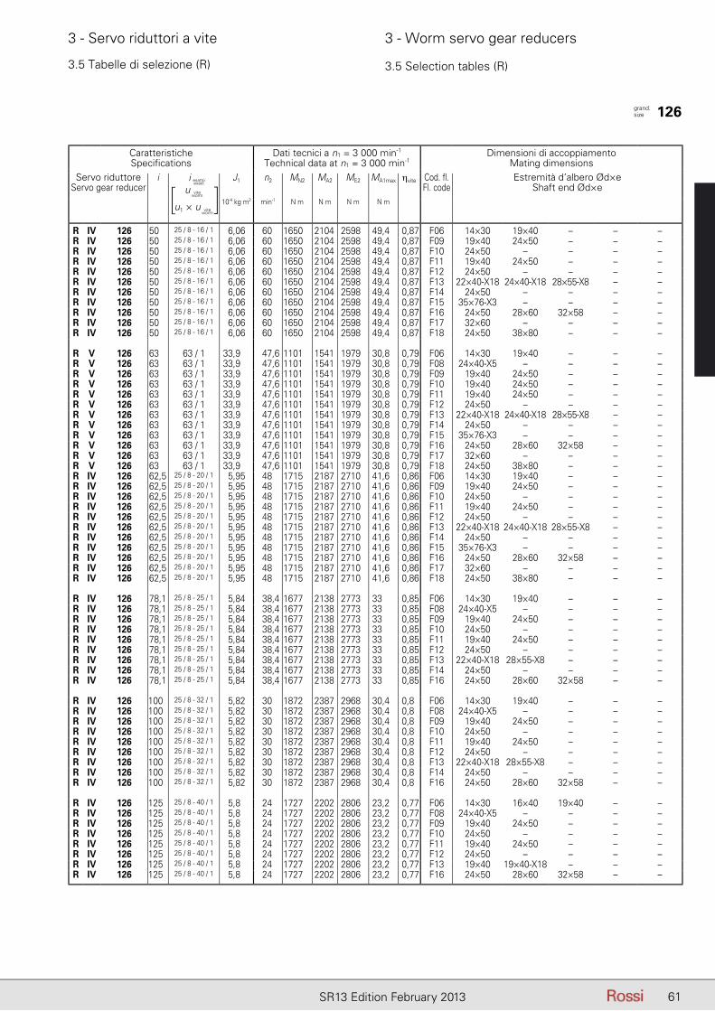
61SR13 Edition February 2013
3 - Servo riduttori a vite 3 - Worm servo gear reducers
3.5 Tabelle di selezione (R) 3.5 Selection tables (R)
CaratteristicheSpecifications
Dati tecnici a n1 = 3 000 min-1
Technical data at n1 = 3 000 min-1Dimensioni di accoppiamento
Mating dimensionsServo riduttore
Servo gear reduceri iesatto - exact J1 n2 MN2 MA2 ME2 MA1max ηvite Cod. fl.
Fl. codeEstremità d’albero Ød×e
Shaft end Ød×e10-4 kg m2 min-1 N m N m N m N m
R IV 126 50 25 / 8 - 16 / 1 6,06 60 1650 2104 2598 49,4 0,87 F06 14×30 19×40 – – –R IV 126 50 25 / 8 - 16 / 1 6,06 60 1650 2104 2598 49,4 0,87 F09 19×40 24×50 – – –R IV 126 50 25 / 8 - 16 / 1 6,06 60 1650 2104 2598 49,4 0,87 F10 24×50 – – – –R IV 126 50 25 / 8 - 16 / 1 6,06 60 1650 2104 2598 49,4 0,87 F11 19×40 24×50 – – –R IV 126 50 25 / 8 - 16 / 1 6,06 60 1650 2104 2598 49,4 0,87 F12 24×50 – – – –R IV 126 50 25 / 8 - 16 / 1 6,06 60 1650 2104 2598 49,4 0,87 F13 22×40-X18 24×40-X18 28×55-X8 – –R IV 126 50 25 / 8 - 16 / 1 6,06 60 1650 2104 2598 49,4 0,87 F14 24×50 – – – –R IV 126 50 25 / 8 - 16 / 1 6,06 60 1650 2104 2598 49,4 0,87 F15 35×76-X3 – – – –R IV 126 50 25 / 8 - 16 / 1 6,06 60 1650 2104 2598 49,4 0,87 F16 24×50 28×60 32×58 – –R IV 126 50 25 / 8 - 16 / 1 6,06 60 1650 2104 2598 49,4 0,87 F17 32×60 – – – –R IV 126 50 25 / 8 - 16 / 1 6,06 60 1650 2104 2598 49,4 0,87 F18 24×50 38×80 – – –
R V 126 63 63 / 1 33,9 47,6 1101 1541 1979 30,8 0,79 F06 14×30 19×40 – – –R V 126 63 63 / 1 33,9 47,6 1101 1541 1979 30,8 0,79 F08 24×40-X5 – – – –R V 126 63 63 / 1 33,9 47,6 1101 1541 1979 30,8 0,79 F09 19×40 24×50 – – –R V 126 63 63 / 1 33,9 47,6 1101 1541 1979 30,8 0,79 F10 19×40 24×50 – – –R V 126 63 63 / 1 33,9 47,6 1101 1541 1979 30,8 0,79 F11 19×40 24×50 – – –R V 126 63 63 / 1 33,9 47,6 1101 1541 1979 30,8 0,79 F12 24×50 – – – –R V 126 63 63 / 1 33,9 47,6 1101 1541 1979 30,8 0,79 F13 22×40-X18 24×40-X18 28×55-X8 – –R V 126 63 63 / 1 33,9 47,6 1101 1541 1979 30,8 0,79 F14 24×50 – – – –R V 126 63 63 / 1 33,9 47,6 1101 1541 1979 30,8 0,79 F15 35×76-X3 – – – –R V 126 63 63 / 1 33,9 47,6 1101 1541 1979 30,8 0,79 F16 24×50 28×60 32×58 – –R V 126 63 63 / 1 33,9 47,6 1101 1541 1979 30,8 0,79 F17 32×60 – – – –R V 126 63 63 / 1 33,9 47,6 1101 1541 1979 30,8 0,79 F18 24×50 38×80 – – –R IV 126 62,5 25 / 8 - 20 / 1 5,95 48 1715 2187 2710 41,6 0,86 F06 14×30 19×40 – – –R IV 126 62,5 25 / 8 - 20 / 1 5,95 48 1715 2187 2710 41,6 0,86 F09 19×40 24×50 – – –R IV 126 62,5 25 / 8 - 20 / 1 5,95 48 1715 2187 2710 41,6 0,86 F10 24×50 – – – –R IV 126 62,5 25 / 8 - 20 / 1 5,95 48 1715 2187 2710 41,6 0,86 F11 19×40 24×50 – – –R IV 126 62,5 25 / 8 - 20 / 1 5,95 48 1715 2187 2710 41,6 0,86 F12 24×50 – – – –R IV 126 62,5 25 / 8 - 20 / 1 5,95 48 1715 2187 2710 41,6 0,86 F13 22×40-X18 24×40-X18 28×55-X8 – –R IV 126 62,5 25 / 8 - 20 / 1 5,95 48 1715 2187 2710 41,6 0,86 F14 24×50 – – – –R IV 126 62,5 25 / 8 - 20 / 1 5,95 48 1715 2187 2710 41,6 0,86 F15 35×76-X3 – – – –R IV 126 62,5 25 / 8 - 20 / 1 5,95 48 1715 2187 2710 41,6 0,86 F16 24×50 28×60 32×58 – –R IV 126 62,5 25 / 8 - 20 / 1 5,95 48 1715 2187 2710 41,6 0,86 F17 32×60 – – – –R IV 126 62,5 25 / 8 - 20 / 1 5,95 48 1715 2187 2710 41,6 0,86 F18 24×50 38×80 – – –
R IV 126 78,1 25 / 8 - 25 / 1 5,84 38,4 1677 2138 2773 33 0,85 F06 14×30 19×40 – – –R IV 126 78,1 25 / 8 - 25 / 1 5,84 38,4 1677 2138 2773 33 0,85 F08 24×40-X5 – – – –R IV 126 78,1 25 / 8 - 25 / 1 5,84 38,4 1677 2138 2773 33 0,85 F09 19×40 24×50 – – –R IV 126 78,1 25 / 8 - 25 / 1 5,84 38,4 1677 2138 2773 33 0,85 F10 24×50 – – – –R IV 126 78,1 25 / 8 - 25 / 1 5,84 38,4 1677 2138 2773 33 0,85 F11 19×40 24×50 – – –R IV 126 78,1 25 / 8 - 25 / 1 5,84 38,4 1677 2138 2773 33 0,85 F12 24×50 – – – –R IV 126 78,1 25 / 8 - 25 / 1 5,84 38,4 1677 2138 2773 33 0,85 F13 22×40-X18 28×55-X8 – – –R IV 126 78,1 25 / 8 - 25 / 1 5,84 38,4 1677 2138 2773 33 0,85 F14 24×50 – – – –R IV 126 78,1 25 / 8 - 25 / 1 5,84 38,4 1677 2138 2773 33 0,85 F16 24×50 28×60 32×58 – –
R IV 126 100 25 / 8 - 32 / 1 5,82 30 1872 2387 2968 30,4 0,8 F06 14×30 19×40 – – –R IV 126 100 25 / 8 - 32 / 1 5,82 30 1872 2387 2968 30,4 0,8 F08 24×40-X5 – – – –R IV 126 100 25 / 8 - 32 / 1 5,82 30 1872 2387 2968 30,4 0,8 F09 19×40 24×50 – – –R IV 126 100 25 / 8 - 32 / 1 5,82 30 1872 2387 2968 30,4 0,8 F10 24×50 – – – –R IV 126 100 25 / 8 - 32 / 1 5,82 30 1872 2387 2968 30,4 0,8 F11 19×40 24×50 – – –R IV 126 100 25 / 8 - 32 / 1 5,82 30 1872 2387 2968 30,4 0,8 F12 24×50 – – – –R IV 126 100 25 / 8 - 32 / 1 5,82 30 1872 2387 2968 30,4 0,8 F13 22×40-X18 28×55-X8 – – –R IV 126 100 25 / 8 - 32 / 1 5,82 30 1872 2387 2968 30,4 0,8 F14 24×50 – – – –R IV 126 100 25 / 8 - 32 / 1 5,82 30 1872 2387 2968 30,4 0,8 F16 24×50 28×60 32×58 – –
R IV 126 125 25 / 8 - 40 / 1 5,8 24 1727 2202 2806 23,2 0,77 F06 14×30 16×40 19×40 – –R IV 126 125 25 / 8 - 40 / 1 5,8 24 1727 2202 2806 23,2 0,77 F08 24×40-X5 – – – –R IV 126 125 25 / 8 - 40 / 1 5,8 24 1727 2202 2806 23,2 0,77 F09 19×40 24×50 – – –R IV 126 125 25 / 8 - 40 / 1 5,8 24 1727 2202 2806 23,2 0,77 F10 24×50 – – – –R IV 126 125 25 / 8 - 40 / 1 5,8 24 1727 2202 2806 23,2 0,77 F11 19×40 24×50 – – –R IV 126 125 25 / 8 - 40 / 1 5,8 24 1727 2202 2806 23,2 0,77 F12 24×50 – – – –R IV 126 125 25 / 8 - 40 / 1 5,8 24 1727 2202 2806 23,2 0,77 F13 19×40 19×40-X18 – – –R IV 126 125 25 / 8 - 40 / 1 5,8 24 1727 2202 2806 23,2 0,77 F16 24×50 28×60 32×58 – –
grand. size 126
i esatto
u
u1 × u
viteworm
viteworm
[ ]i esatto
exact
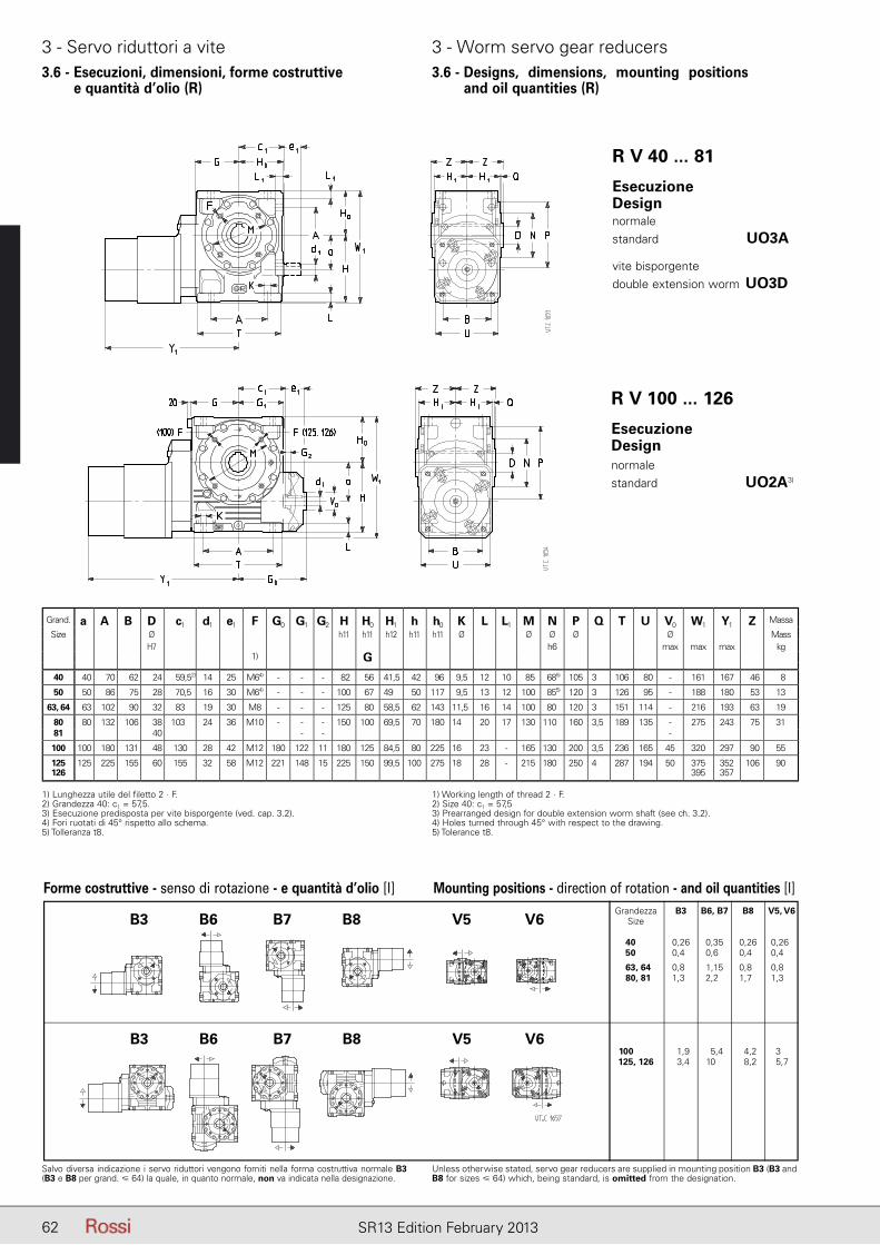
62 SR13 Edition February 2013
3 - Servo riduttori a vite 3 - Worm servo gear reducers3.6 - Esecuzioni, dimensioni, forme costruttive
e quantità d’olio (R)3.6 - Designs, dimensions, mounting positions
and oil quantities (R)
R V 40 ... 81
R V 100 ... 126
Salvo diversa indicazione i servo riduttori vengono forniti nella forma costruttiva normale B3 (B3 e B8 per grand. � 64) la quale, in quanto normale, non va indicata nella designazione.
Unless otherwise stated, servo gear reducers are supplied in mounting position B3 (B3 and B8 for sizes � 64) which, being standard, is omitted from the designation.
EsecuzioneDesign normalestandard UO3A1) 5)
vite bisporgentedouble extension worm UO3D1) 5)
5)
EsecuzioneDesign normalestandard UO2A3) 5)
1) Lunghezza utile del filetto 2 · F.2) Grandezza 40: c1 = 57,5.3) Esecuzione predisposta per vite bisporgente (ved. cap. 3.2).4) Fori ruotati di 45° rispetto allo schema.5) Tolleranza t8.
1) Working length of thread 2 · F.2) Size 40: c1 = 57,53) Prearranged design for double extension worm shaft (see ch. 3.2).4) Holes turned through 45° with respect to the drawing.5) Tolerance t8.
Forme costruttive - senso di rotazione - e quantità d’olio [l] Mounting positions - direction of rotation - and oil quantities [l] Grandezza B3 B6, B7 B8 V5, V6 Size
40, 81 0,26 0,35 0,26 0,26 50, 81 0,46 0,62 0,42 0,42
63, 64 0,86 1,15 0,82 0,82 80, 81 1,36 2,22 1,72 1,32
100, 8 1 1,9 5,4 4,2 3,7 125, 126 3,4 10,4 8,2 5,7
B3 B6 B7 B8 V5 V6
B3 B6 B7 B8 V5 V6
Grand. a A B D c1 d1 e1 F G0 G1 G2 H H0 H1 h h0 K L L1 M N P Q T U V0 W1 Y1 Z Massa
Size Ø h11 h11 h12 h11 h11 Ø Ø Ø Ø Ø MassH7 h6 max max max kg
1) G
40 40 70 62 24 59,52) 14 25 M64) - - - 82 56 41,5 42 96 9,5 12 10 85 685) 105 3 106 80 - 161 167 46 8
50 50 86 75 28 70,5 16 30 M64) - - - 100 67 49 50 117 9,5 13 12 100 855) 120 3 126 95 - 188 180 53 13
63, 64 63 102 90 32 83 19 30 M8 - - - 125 80 58,5 62 143 11,5 16 14 100 80 120 3 151 114 - 216 193 63 19
80 80 132 106 38 103 24 36 M10 - - - 150 100 69,5 70 180 14 20 17 130 110 160 3,5 189 135 - 275 243 75 3181 40 - - -
100 100 180 131 48 130 28 42 M12 180 122 11 180 125 84,5 80 225 16 23 - 165 130 200 3,5 236 165 45 320 297 90 55
125 126
125 225 155 60 155 32 58 M12 221 148 15 225 150 99,5 100 275 18 28 - 215 180 250 4 287 194 50 375395
352357
106 90
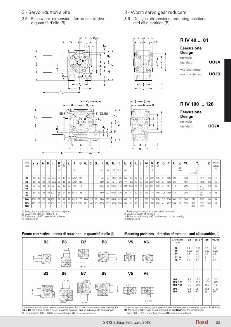
63SR13 Edition February 2013
3 - Servo riduttori a vite 3 - Worm servo gear reducers3.6 - Esecuzioni, dimensioni, forme costruttive
e quantità d’olio (R)3.6 - Designs, dimensions, mounting positions
and oil quantities (R)
1) Esecuzione predisposta per vite sporgente.2) Lunghezza utile del filetto 2 · F.3) Fori ruotati di 45° rispetto allo schema.4) Tolleranza t8.
1) Prearranged design for worm shaft extension.2) Working length of thread 2 · F.3) Holes turned through 45° with respect to the drawing.4) Tolerance t8.
Salvo diversa indicazione i servo riduttori vengono forniti nella forma costruttiva normale B3 (B3 e B8 per grand. � 64) la quale, in quanto normale, non va indicata nella designazione.1) Per grandezze 100 ... 126 la forma costruttiva B6, ha un sovrapprezzo.
Unless otherwise stated, servo gear reducers are supplied in mounting position B3 (B3 and B8 for sizes � 64) which, being standard, is omitted from the designation.1) Sizes 100 ... 126 in mounting position B6 carry a price addition.
R IV 40 ... 81
R IV 100 ... 126
EsecuzioneDesign normalestandard UO3A1)
vite sporgenteworm extension UO3D1)
EsecuzioneDesign normalestandard UO2A1) )
Forme costruttive - senso di rotazione - e quantità d’olio [l] Mounting positions - direction of rotation - and oil quantities [l] Grandezza B3 B6, B7 B8 V5, V6 Size
32, 81 0,26 0,25 0,20 0,26 40, 81 0,32 0,45 0,32 0,32 50, 81 0,56 0,72 0,50 0,52
63, 64 1,86 1,35 1,82 1,82 80, 81 1,56 2,52 2,72 1,52
100, 8 1 2,1 6,3 4,5 3,3 125, 126 3,8 11,6 8,8 6,3 160, 161 6,5 20,8 16,5 11,2
200, 126 10,46 38,2 31,5 21,2 250, 126 18,36 67,2 53,2 35,7
B3 B6 B7 B8 V5 V6
B3 B6 B7 B8 V5 V6
Grand. a a1 A B c1 D d1 e1 F G G0 G1 G2 H H0 H1 h h0 K L L1M N P Q T U V0 W1 Y1 Z Massa
Size Ø Ø Ø Ø Ø Ø MassØ kg
H7 2) h11 h11 h12 h11 h11 h6 max maxiN ≥ 200
40 40 40 70 62 57,5 24 14 25 M63) 87 - - - 82 56 41,5 82 56 9,5 12 10 85 684) 105 3 106 80 - 138 157 46 9
50 50 40 86 75 70,5 28 16 30 M63) 98 - - - 100 67 49 90 77 9,5 13 12 100 854) 120 3 126 95 - 167 183 53 13
63 63 50 102 90 83 32 19 30 M8 118 - - - 125 80 58,5 112 93 11,5 16 14 100 80 120 3 151 114 - 205 211 63 2364 223
80 80 50 132 106 103 38 24 36 M10 138 - - - 150 100 69,5 120 130 14 20 17 130 110 160 3,5 189 135 - 250 251 75 3381 40 - - - 251
100 100 63 180 131 130 48 28 42 M12 170 180 122 11 180 125 84,5 143 162 16 23 - 165 130 200 3,5 236 165 45 305 273 297 90 61
125 125 80 225 155 155 60 32 58 M12 205 221 148 15 225 150 99,5 180 195 18 28 - 215 180 200 4 287 194 50 375 332 352 106 97126 - - - 332 352
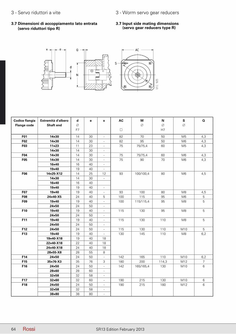
64 SR13 Edition February 2013
3 - Servo riduttori a vite 3 - Worm servo gear reducers
3.7 Dimensioni di accoppiamento lato entrata (servo riduttori tipo R)
3.7 Input side mating dimensions (servo gear reducers type R)
Ø □ Ø Ø ØF7 H7
14 30 – 70 50 M5
14 30 – 95 50 M6
11 23 – 75/75,4 60 M5
14 30 –
14 30 – 75/75,4 60 M6
14 30 – 90 70 M6
16 40 –
19 40 –
14 25 12 100/100,4 80 M6
14 30 –
16 40 –
19 40 –
19 40 – 100 80 M8
24 40 5 115 95 M6
19 40 – 115/115,4 95 M8
24 50 –
19 40 – 130 95 M8
24 50 –
19 40 – 130 110 M8
24 50 –
24 50 – 130 110 M10
19 40 – 145 110 M8
19 40 18
22 40 18
24 40 18
28 55 8
24 50 – 165 110 M10
35 76 3 200 114 M12
24 50 – 165/165,4 130 M10
28 60 –
32 58 –
32 60 – 215 130 M10
24 50 – 215 180 M12
32 58 –
38 80 –
Codice flangiaFlange code
Estremità d'alberoShaft end
Codice fl angia Estremità d'albero d e x AC M N S QFlange code Shaft end ∅ ∅ ∅ ∅
F7 H7
F01 14×30 14 30 - 82 70 50 M5 4,3F02 14×30 14 30 - 82 95 50 M6 4,3F03 11×23 11 23 - 75 75/75,4 60 M5 4,3
14×30 14 30 -F04 14×30 14 30 - 75 75/75,4 60 M6 4,3F05 14×30 14 30 - 75 90 70 M6 4,3
16×40 16 40 -19×40 19 40 -
F06 14×25-X12 14 25 12 93 100/100,4 80 M6 4,514×30 14 30 -16×40 16 4019×40 19 40 -
F07 19×40 19 40 - 93 100 80 M8 4,5F08 24×40-X5 24 40 5 100 115 95 M6 5F09 19×40 19 40 - 100 115/115,4 95 M8 5
24×50 24 50 -F10 19×40 19 40 - 115 130 95 M8 5
24×50 24 50 -F11 19×40 19 40 - 115 130 110 M8 5
24×50 24 50 -F12 24×50 24 50 - 115 130 110 M10 5F13 19×40 19 40 - 130 145 110 M8 6,2
19×40-X18 19 40 1822×40-X18 22 40 1824×40-X18 24 40 1828×55-X8 28 55 8
F14 24×50 24 50 - 142 165 110 M10 6,2F15 35×76-X3 35 76 3 180 200 114,3 M12 7F16 24×50 24 50 - 142 165/165,4 130 M10 6
28×60 28 60 -32×58 32 58 -
F17 32×60 32 60 - 190 215 130 M10 6F18 24×50 24 50 - 190 215 180 M12 6
32×58 32 58 -38×80 38 80 -

65SR13 Edition February 2013
Pagina lasciata intenzionalmente biancaThis page is intentionally left blank
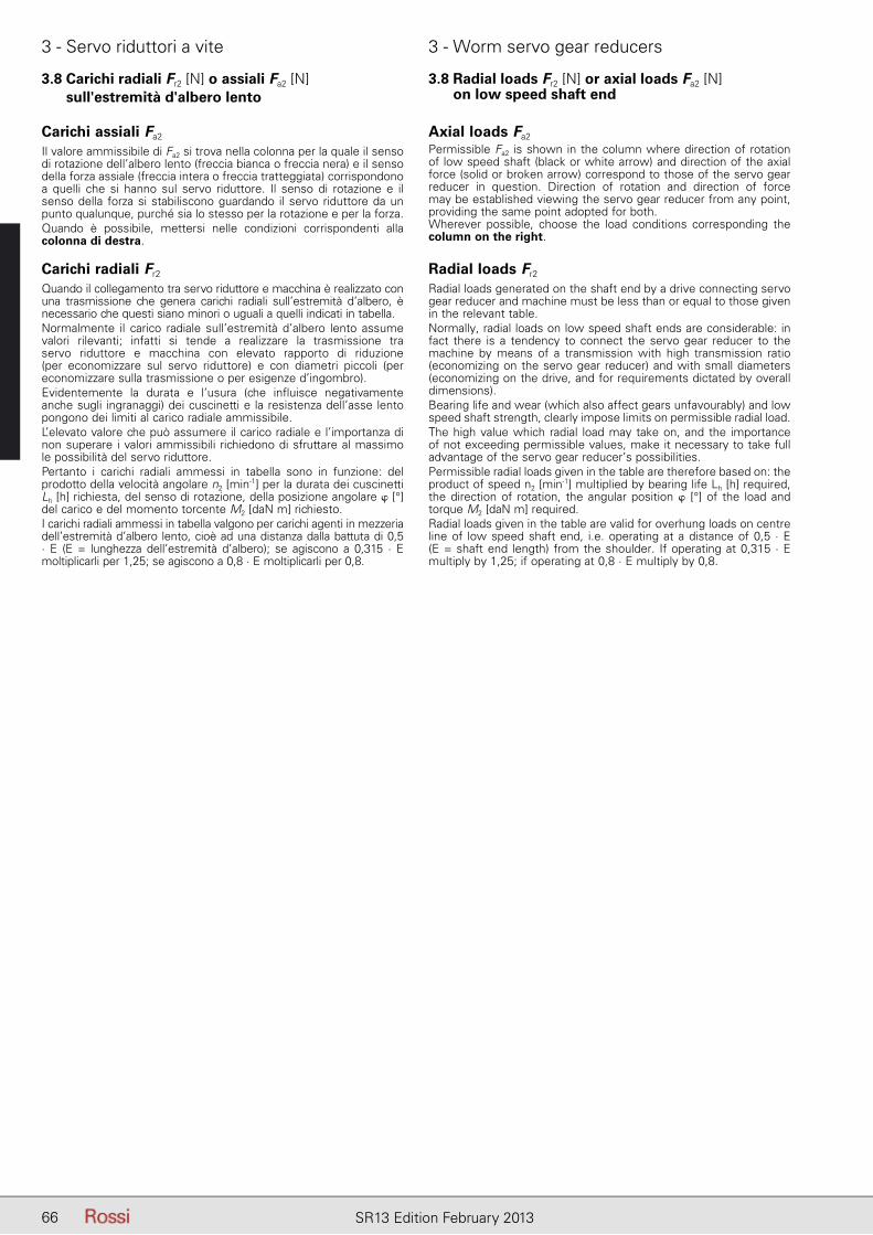
66 SR13 Edition February 2013
3 - Servo riduttori a vite 3 - Worm servo gear reducers
3.8 Carichi radiali Fr2 [N] o assiali Fa2 [N] sull'estremità d'albero lento
3.8 Radial loads Fr2 [N] or axial loads Fa2 [N] on low speed shaft end
Carichi assiali Fa2
Il valore ammissibile di Fa2 si trova nella colonna per la quale il senso di rotazione dell’albero lento (freccia bianca o freccia nera) e il sen so della forza assiale (freccia intera o freccia tratteggiata) corrispondono a quelli che si hanno sul servo riduttore. Il senso di rotazione e il senso della forza si stabiliscono guardando il servo riduttore da un punto qualunque, purché sia lo stesso per la rotazione e per la forza.Quando è possibile, mettersi nelle condizioni corrispondenti alla colonna di destra.
Carichi radiali Fr2
Quando il collegamento tra servo riduttore e macchina è realizzato con una trasmissione che genera carichi radiali sull’estremità d’albero, è ne cessario che questi siano minori o uguali a quelli indicati in tabella.Normalmente il carico radiale sull’estremità d’albero lento assume valori rilevanti; infatti si tende a realizzare la trasmissione tra servo riduttore e macchina con elevato rapporto di riduzione (per economizzare sul servo riduttore) e con diametri piccoli (per economizzare sulla trasmissione o per esigenze d’ingombro).Evidentemente la durata e l’usura (che influisce negativamente an che sugli ingranaggi) dei cuscinetti e la resistenza dell’asse lento pongono dei limiti al carico radiale ammissibile.L’elevato valore che può assumere il carico radiale e l’importanza di non superare i valori ammissibili richiedono di sfruttare al massimo le possibilità del servo riduttore.Pertanto i carichi radiali ammessi in tabella sono in funzione: del prodotto della velocità angolare n2 [min-1] per la durata dei cuscinetti Lh [h] richiesta, del senso di rotazione, della posizione angolare � [°] del carico e del momento torcente M2 [daN m] richiesto.I carichi radiali ammessi in tabella valgono per carichi agenti in mezzeria dell’estremità d’albero lento, cioè ad una distanza dalla battuta di 0,5 · E (E = lunghezza dell’estremità d’albero); se agiscono a 0,315 · E moltiplicarli per 1,25; se agiscono a 0,8 · E moltiplicarli per 0,8.
Axial loads Fa2
Permissible Fa2 is shown in the column where direction of rotation of low speed shaft (black or white arrow) and direction of the axial force (solid or broken arrow) correspond to those of the servo gear reducer in question. Direction of rotation and direction of force may be established viewing the servo gear reducer from any point, providing the same point adopted for both.Wherever possible, choose the load conditions corresponding the column on the right.
Radial loads Fr2
Radial loads generated on the shaft end by a drive connecting servo gear reducer and machine must be less than or equal to those given in the relevant table.Normally, radial loads on low speed shaft ends are considerable: in fact there is a tendency to connect the servo gear reducer to the machine by means of a transmission with high transmission ratio (economizing on the servo gear reducer) and with small diameters (economizing on the drive, and for requirements dictated by overall dimensions).Bearing life and wear (which also affect gears unfavourably) and low speed shaft strength, clearly impose limits on permissible radial load.The high value which radial load may take on, and the importance of not exceeding permissible values, make it necessary to take full advantage of the servo gear reducer’s possibilities.Permissible radial loads given in the table are therefore based on: the product of speed n2 [min-1] multiplied by bearing life Lh [h] required, the direction of rotation, the angular position � [°] of the load and torque M2 [daN m] required.Radial loads given in the table are valid for overhung loads on centre line of low speed shaft end, i.e. operating at a distance of 0,5 · E (E = shaft end length) from the shoulder. If operating at 0,315 · Emultiply by 1,25; if operating at 0,8 · E multiply by 0,8.

67SR13 Edition February 2013
3 - Servo riduttori a vite 3 - Worm servo gear reducers
3.8 Carichi radiali Fr2 [N] o assiali Fa2 [N] sull'estremità d'albero lento
3.8 Radial loads Fr2 [N] or axial loads Fa2 [N] on low speed shaft end
Per i casi di trasmissione più comuni, il carico radiale Fr2 ha il valore e la posizione angolare seguenti:
Radial load Fr2 for most common drives has the following value and angular position:
dove: P2 [kW] è la potenza richiesta all’uscita del riduttore, n2 [min-1] è la velocità angolare, d [m] è il diametro primitivo.
IMPORTANTE: 0° coincide con la semiretta parallela all’asse della vite e orientata come sopra raffigurato, pertanto segue la rotazione dell’asse della vite come sotto indicato.
where: P2 [kW] is power required at the output side of the gear re-ducer, n2 [min-1] is the speed, d [m] is the pitch diameter.
IMPORTANT: 0° coincides with a half line lying parallel to the worm axis, and oriented as shown above, and therefore it follows the rotation of the worm axis as shown below.
Fr2 = 28 650 · P2
d · n2 [daN]
per cinghia dentata
for timing belt drive
Fr2 = 47 750 · P2
d · n2 [daN]
per trasmissione a cinghie trapezoidali
for V-belt drive
Fr2 = 20 320 · P2
d · n2 [daN]
per trasmissione ad ingranaggio cilindrico diritto
for spur gear pair drive
RotazioneRotation
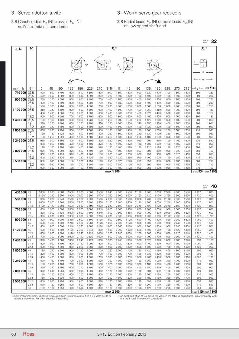
68 SR13 Edition February 2013
3 - Servo riduttori a vite 3 - Worm servo gear reducers
3.8 Carichi radiali Fr2 [N] o assiali Fa2 [N] sull'estremità d'albero lento
3.8 Radial loads Fr2 [N] or axial loads Fa2 [N] on low speed shaft end
n2.Lh M2 Fr2
1) Fa21)
min-1 . h N m 0 45 90 135 180 225 270 315 0 45 90 135 180 225 270 315710 000 37,5 1 400 1 500 1 700 1 800 1 800 1 800 1 800 1 600 1 800 1 800 1 500 1 320 1 400 1 700 1 800 1 800 800 1 250
26,5 1 500 1 600 1 800 1 800 1 800 1 800 1 800 1 700 1 800 1 800 1 700 1 500 1 500 1 700 1 800 1 800 800 1 250
900 000 37,5 1 250 1 320 1 600 1 800 1 800 1 800 1 700 1 400 1 800 1 800 1 400 1 250 1 250 1 500 1 800 1 800 800 1 25026,5 1 400 1 400 1 600 1 800 1 800 1 800 1 700 1 500 1 800 1 800 1 500 1 400 1 400 1 600 1 800 1 800 800 1 25019 1 500 1 500 1 700 1 800 1 800 1 800 1 700 1 600 1 800 1 800 1 600 1 500 1 500 1 600 1 800 1 800 800 1 250
1 120 000 26,5 1 250 1 320 1 500 1 800 1 800 1 800 1 600 1 400 1 800 1 700 1 400 1 250 1 250 1 500 1 700 1 800 800 1 12019 1 400 1 400 1 500 1 700 1 800 1 800 1 600 1 400 1 800 1 600 1 400 1 320 1 400 1 500 1 700 1 800 800 1 18013,2 1 400 1 500 1 600 1 700 1 800 1 700 1 600 1 500 1 800 1 600 1 500 1 400 1 400 1 500 1 700 1 800 800 1 180
1 400 000 26,5 1 180 1 180 1 400 1 600 1 800 1 700 1 500 1 250 1 800 1 500 1 250 1 120 1 180 1 350 1 600 1 800 800 1 06019 1 250 1 320 1 400 1 600 1 700 1 700 1 500 1 320 1 700 1 500 1 320 1 250 1 250 1 400 1 600 1 700 800 1 06013,2 1 320 1 320 1 400 1 600 1 600 1 600 1 500 1 400 1 600 1 500 1 400 1 320 1 320 1 400 1 600 1 700 800 1 060
1 800 000 26,5 1 060 1 060 1 250 1 500 1 700 1 600 1 400 1 180 1 700 1 400 1 180 1 000 1 060 1 250 1 500 1 700 710 95019 1 120 1 180 1 320 1 500 1 600 1 500 1 400 1 250 1 600 1 400 1 250 1 120 1 120 1 250 1 500 1 600 800 95013,2 1 180 1 250 1 320 1 400 1 500 1 500 1 400 1 250 1 500 1 400 1 250 1 180 1 180 1 320 1 400 1 500 800 950
2 240 000 26,5 950 1 000 1 180 1 400 1 600 1 500 1 320 1 060 1 600 1 320 1 060 900 950 1 120 1 400 1 600 630 85019 1 060 1 060 1 180 1 400 1 500 1 400 1 320 1 120 1 500 1 320 1 120 1 000 1 060 1 180 1 400 1 500 710 85013,2 1 120 1 120 1 250 1 320 1 400 1 400 1 320 1 180 1 400 1 320 1 180 1 120 1 120 1 180 1 320 1 400 800 900
2 800 000 26,5 850 900 1 060 1 320 1 500 1 400 1 180 950 1 500 1 250 950 800 850 1 000 1 320 1 500 560 75019 950 1 000 1 120 1 320 1 400 1 400 1 180 1 060 1 400 1 250 1 000 950 950 1 060 1 320 1 400 630 80013,2 1 000 1 060 1 120 1 250 1 320 1 320 1 180 1 060 1 320 1 250 1 060 1 000 1 000 1 120 1 250 1 320 710 800
3 550 000 19 850 900 1 000 1 180 1 320 1 250 1 120 950 1 320 1 120 950 850 850 1 000 1 180 1 320 560 71013,2 950 950 1 060 1 180 1 250 1 250 1 120 1 000 1 250 1 120 1 000 900 950 1 000 1 180 1 250 630 7109,5 1 000 1 000 1 060 1 180 1 180 1 180 1 120 1 000 1 180 1 120 1 000 950 1 000 1 060 1 180 1 250 670 750
max 1 800 max 800 max 1 250
450 000 63 2 000 2 000 2 360 2 500 2 500 2 500 2 500 2 240 2 500 2 500 2 120 1 900 2 000 2 360 2 500 2 500 1 120 1 80045 2 120 2 240 2 500 2 500 2 500 2 500 2 500 2 360 2 500 2 500 2 360 2 120 2 120 2 360 2 500 2 500 1 120 1 800
560 000 63 1 800 1 900 2 240 2 500 2 500 2 500 2 500 2 000 2 500 2 500 2 000 1 700 1 800 2 120 2 500 2 500 1 120 1 80045 2 000 2 000 2 360 2 500 2 500 2 500 2 500 2 120 2 500 2 500 2 120 1 900 2 000 2 240 2 500 2 500 1 120 1 80031,5 2 120 2 120 2 360 2 500 2 500 2 500 2 500 2 240 2 500 2 500 2 240 2 120 2 120 2 240 2 500 2 500 1 120 1 800
710 000 63 1 600 1 700 2 000 2 500 2 500 2 500 2 240 1 800 2 500 2 360 1 800 1 500 1 600 1 900 2 500 2 500 1 120 1 60045 1 800 1 900 2 120 2 500 2 500 2 500 2 240 1 900 2 500 2 360 1 900 1 700 1 800 2 000 2 500 2 500 1 120 1 60031,5 1 900 2 000 2 120 2 360 2 500 2 500 2 240 2 000 2 500 2 360 2 000 1 900 1 900 2 120 2 360 2 500 1 120 1 700
900 000 63 1 400 1 500 1 900 2 360 2 500 2 500 2 120 1 600 2 500 2 120 1 600 1 400 1 400 1 800 2 360 2 500 1 060 1 40045 1 600 1 700 1 900 2 240 2 500 2 360 2 120 1 800 2 500 2 120 1 800 1 600 1 600 1 900 2 240 2 500 1 120 1 50031,5 1 800 1 800 2 000 2 240 2 360 2 360 2 120 1 900 2 360 2 120 1 900 1 700 1 700 1 900 2 240 2 360 1 120 1 500
1 120 000 45 1 500 1 500 1 800 2 120 2 360 2 240 1 900 1 600 2 360 2 000 1 600 1 400 1 500 1 700 2 120 2 360 1 060 1 32031,5 1 600 1 600 1 800 2 120 2 240 2 120 2 000 1 700 2 240 2 000 1 700 1 600 1 600 1 800 2 120 2 240 1 120 1 40022,4 1 700 1 700 1 900 2 000 2 120 2 120 2 000 1 800 2 120 2 000 1 800 1 700 1 700 1 800 2 000 2 120 1 120 1 400
1 400 000 45 1 320 1 400 1 600 2 000 2 240 2 120 1 800 1 500 2 240 1 800 1 500 1 320 1 320 1 600 2 000 2 240 950 1 18031,5 1 500 1 500 1 700 1 900 2 120 2 000 1 800 1 600 2 120 1 800 1 600 1 400 1 500 1 600 1 900 2 120 1 060 1 25022,4 1 600 1 600 1 700 1 900 2 000 2 000 1 800 1 600 2 000 1 800 1 600 1 500 1 600 1 700 1 900 2 000 1 120 1 250
1 800 000 45 1 180 1 250 1 500 1 900 2 120 2 000 1 700 1 320 2 000 1 700 1 320 1 120 1 180 1 400 1 800 2 120 800 1 06031,5 1 320 1 400 1 500 1 800 1 900 1 900 1 700 1 400 1 900 1 700 1 400 1 320 1 320 1 500 1 800 2 000 900 1 12022,4 1 400 1 400 1 600 1 800 1 900 1 800 1 700 1 500 1 900 1 700 1 500 1 400 1 400 1 500 1 700 1 900 1 000 1 120
2 240 000 45 1 060 1 120 1 400 1 700 2 000 1 900 1 500 1 250 1 900 1 600 1 180 1 060 1 060 1 320 1 700 2 000 710 95031,5 1 180 1 250 1 400 1 700 1 800 1 800 1 500 1 320 1 800 1 600 1 320 1 180 1 180 1 400 1 700 1 900 800 1 00022,4 1 320 1 320 1 500 1 600 1 700 1 700 1 500 1 400 1 700 1 600 1 400 1 250 1 320 1 400 1 600 1 800 900 1 000
2 800 000 45 1 000 1 000 1 250 1 600 1 900 1 800 1 400 1 120 1 800 1 500 1 120 900 950 1 180 1 600 1 900 600 90031,5 1 120 1 120 1 320 1 600 1 700 1 700 1 400 1 180 1 700 1 500 1 180 1 060 1 120 1 250 1 500 1 700 710 90022,4 1 180 1 250 1 320 1 500 1 600 1 600 1 400 1 250 1 600 1 500 1 250 1 180 1 180 1 320 1 500 1 700 800 950
3 550 000 31,5 1 000 1 060 1 250 1 500 1 600 1 500 1 320 1 120 1 600 1 320 1 120 950 1 000 1 180 1 400 1 600 630 80022,4 1 060 1 120 1 250 1 400 1 500 1 500 1 320 1 180 1 500 1 320 1 180 1 060 1 060 1 250 1 400 1 500 710 85016 1 180 1 180 1 250 1 400 1 500 1 400 1 320 1 180 1 500 1 320 1 180 1 120 1 180 1 250 1 400 1 500 750 850
max 2 500 max 1 120 max 1 8001) Contemporaneamente al carico radiale può agire un carico assiale fino a 0,2 volte quello di
tabella e viceversa. Per valori superiori interpellarci.1) An axial load of up to 0,2 times the value in the table is permissible, simultaneously with
the radial load. If exceeded consult us.
grand.size 32
grand.size 40

69SR13 Edition February 2013
3 - Servo riduttori a vite 3 - Worm servo gear reducers
3.8 Carichi radiali Fr2 [N] o assiali Fa2 [N] sull'estremità d'albero lento
3.8 Radial loads Fr2 [N] or axial loads Fa2 [N] on low speed shaft end
n2.Lh M2 Fr2
1) Fa21)
min-1 . h N m 0 45 90 135 180 225 270 315 0 45 90 135 180 225 270 315450 000 125 2 240 2 360 2 800 3 550 3 550 3 550 3 150 2 500 3 550 3 350 2 500 2 120 2 120 2 650 3 550 3 550 1 600 2 360
90 2 500 2 650 3 000 3 550 3 550 3 550 3 150 2 650 3 550 3 350 2 650 2 360 2 500 2 800 3 550 3 550 1 600 2 50063 2 650 2 800 3 150 3 350 3 550 3 550 3 150 2 800 3 550 3 350 2 800 2 650 2 650 3 000 3 350 3 550 1 600 2 50045 2 800 2 800 3 150 3 350 3 550 3 550 3 150 3 000 3 550 3 350 3 000 2 800 2 800 3 000 3 350 3 550 1 600 2 500
560 000 125 2 000 2 120 2 650 3 350 3 550 3 550 3 000 2 240 3 550 3 000 2 240 1 900 2 000 2 500 3 350 3 550 1 500 2 12090 2 240 2 360 2 800 3 350 3 550 3 550 3 000 2 500 3 550 3 000 2 500 2 120 2 240 2 650 3 350 3 550 1 600 2 24063 2 500 2 500 2 800 3 150 3 350 3 350 3 000 2 650 3 350 3 000 2 650 2 360 2 500 2 800 3 150 3 550 1 600 2 36045 2 650 2 650 2 800 3 150 3 350 3 150 3 000 2 800 3 350 3 000 2 800 2 500 2 650 2 800 3 150 3 350 1 600 2 360
710 000 125 1 800 1 900 2 360 3 150 3 550 3 550 2 650 2 000 3 550 2 800 2 000 1 600 1 700 2 240 3 150 3 550 1 320 1 90090 2 000 2 120 2 500 3 150 3 350 3 350 2 800 2 240 3 350 2 800 2 240 2 000 2 000 2 360 3 000 3 550 1 600 2 00063 2 240 2 360 2 650 3 000 3 150 3 150 2 800 2 360 3 150 2 800 2 360 2 240 2 240 2 500 3 000 3 350 1 600 2 12045 2 360 2 500 2 650 3 000 3 150 3 000 2 800 2 500 3 150 2 800 2 500 2 360 2 360 2 650 2 800 3 150 1 600 2 120
900 000 125 1 600 1 700 2 240 3 000 3 550 3 150 2 500 1 800 3 350 2 500 1 800 1 400 1 500 2 000 2 800 3 550 1 120 1 70090 1 800 1 900 2 360 2 800 3 150 3 000 2 500 2 000 3 150 2 650 2 000 1 700 1 800 2 240 2 800 3 350 1 400 1 80063 2 000 2 120 2 360 2 800 3 000 2 800 2 500 2 240 3 000 2 650 2 240 2 000 2 000 2 360 2 800 3 150 1 600 1 90045 2 240 2 240 2 500 2 650 2 800 2 800 2 500 2 360 2 800 2 650 2 360 2 120 2 120 2 360 2 650 2 800 1 600 1 900
1 120 000 90 1 700 1 700 2 120 2 650 3 000 2 800 2 360 1 900 3 000 2 360 1 800 1 600 1 600 2 000 2 650 3 150 1 180 1 60063 1 900 1 900 2 240 2 650 2 800 2 800 2 360 2 000 2 800 2 360 2 000 1 800 1 900 2 120 2 650 2 800 1 400 1 70045 2 000 2 000 2 240 2 500 2 650 2 650 2 360 2 120 2 650 2 360 2 120 2 000 2 000 2 240 2 500 2 800 1 500 1 800
1 400 000 90 1 500 1 600 2 000 2 500 2 800 2 650 2 120 1 700 2 800 2 240 1 700 1 400 1 400 1 800 2 500 3 000 1 000 1 50063 1 700 1 800 2 000 2 500 2 650 2 500 2 240 1 900 2 650 2 240 1 800 1 600 1 700 2 000 2 360 2 650 1 250 1 60045 1 800 1 900 2 120 2 360 2 500 2 500 2 240 2 000 2 500 2 240 2 000 1 800 1 800 2 000 2 360 2 500 1 320 1 600
1 800 000 90 1 320 1 400 1 800 2 360 2 650 2 500 2 000 1 500 2 650 2 000 1 500 1 250 1 250 1 600 2 240 2 800 850 1 32063 1 500 1 600 1 900 2 240 2 500 2 360 2 000 1 700 2 500 2 120 1 700 1 500 1 500 1 800 2 240 2 500 1 060 1 40045 1 700 1 700 1 900 2 240 2 360 2 240 2 000 1 800 2 360 2 120 1 800 1 600 1 600 1 900 2 240 2 360 1 180 1 400
2 240 000 90 1 180 1 250 1 600 2 240 2 500 2 360 1 800 1 400 2 500 1 900 1 320 1 060 1 120 1 500 2 120 2 650 750 1 18063 1 400 1 400 1 700 2 120 2 360 2 240 1 900 1 500 2 360 1 900 1 500 1 320 1 320 1 600 2 120 2 360 950 1 25045 1 500 1 600 1 800 2 000 2 240 2 120 1 900 1 600 2 240 1 900 1 600 1 500 1 500 1 700 2 000 2 240 1 060 1 320
2 800 000 90 1 060 1 120 1 500 2 000 2 360 2 240 1 700 1 250 2 360 1 800 1 180 950 1 000 1 320 2 000 2 500 630 1 06063 1 250 1 320 1 600 2 000 2 240 2 120 1 700 1 400 2 240 1 800 1 400 1 180 1 250 1 500 2 000 2 240 800 1 12045 1 400 1 400 1 600 1 900 2 120 2 000 1 700 1 500 2 120 1 800 1 500 1 320 1 400 1 600 1 900 2 120 950 1 18031,5 1 500 1 500 1 700 1 900 2 000 1 900 1 800 1 600 2 000 1 800 1 600 1 500 1 500 1 600 1 900 2 000 1 000 1 180
3 550 000 63 1 120 1 180 1 400 1 800 2 120 2 000 1 600 1 250 2 000 1 600 1 250 1 060 1 120 1 400 1 800 2 120 710 1 00045 1 250 1 320 1 500 1 800 2 000 1 900 1 600 1 400 1 900 1 700 1 320 1 180 1 250 1 400 1 800 2 000 850 1 06031,5 1 320 1 400 1 500 1 700 1 800 1 800 1 600 1 400 1 800 1 700 1 400 1 320 1 320 1 500 1 700 1 900 900 1 060
max 3 550 max 1 600 max 2 500
grand.size 50
1) Contemporaneamente al carico radiale può agire un carico assiale fino a 0,2 volte quello di tabella e viceversa. Per valori superiori interpellarci.
1) An axial load of up to 0,2 times the value in the table is permissible, simultaneously with the radial load. If exceeded consult us.
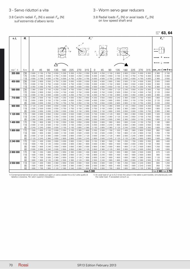
70 SR13 Edition February 2013
3 - Servo riduttori a vite 3 - Worm servo gear reducers
n2.Lh M2 Fr2
1) Fa21)
min-1 . h N m 0 45 90 135 180 225 270 315 0 45 90 135 180 225 270 315355 000 236 2 800 3 150 3 750 5 000 5 300 5 300 4 250 3 350 5 300 4 250 3 150 2 650 2 800 3 550 5 000 5 300 2 360 3 150
170 3 350 3 350 4 000 4 750 5 300 5 000 4 250 3 550 5 300 4 500 3 550 3 150 3 150 3 750 4 750 5 300 2 360 3 350118 3 550 3 750 4 000 4 750 5 000 4 750 4 250 3 750 5 000 4 500 3 750 3 550 3 550 4 000 4 750 5 000 2 360 3 550
450 000 236 2 500 2 800 3 550 4 750 5 300 5 000 4 000 3 000 5 300 4 000 2 800 2 360 2 500 3 150 4 500 5 300 2 000 2 800170 3 000 3 150 3 750 4 500 5 000 4 750 4 000 3 350 5 000 4 000 3 150 2 800 2 800 3 550 4 500 5 000 2 360 3 000118 3 350 3 350 3 750 4 250 4 750 4 500 4 000 3 550 4 500 4 000 3 550 3 150 3 150 3 750 4 250 4 750 2 360 3 150
560 000 236 2 360 2 500 3 150 4 250 5 000 4 750 3 550 2 650 5 000 3 750 2 650 2 120 2 240 3 000 4 250 5 300 1 700 2 650170 2 650 2 800 3 350 4 250 4 750 4 500 3 750 3 000 4 500 3 750 3 000 2 500 2 650 3 150 4 000 4 750 2 120 2 650118 3 000 3 150 3 550 4 000 4 250 4 250 3 750 3 150 4 250 3 750 3 150 2 800 3 000 3 350 4 000 4 500 2 360 2 800
710 000 170 2 360 2 500 3 150 4 000 4 250 4 000 3 350 2 650 4 250 3 550 2 650 2 240 2 360 3 000 3 750 4 500 1 800 2 500118 2 650 2 800 3 150 3 750 4 000 4 000 3 350 3 000 4 000 3 550 2 800 2 650 2 650 3 150 3 750 4 250 2 120 2 50085 2 800 3 000 3 350 3 750 3 750 3 750 3 350 3 150 3 750 3 550 3 000 2 800 2 800 3 150 3 750 4 000 2 240 2 650
900 000 170 2 120 2 240 2 800 3 550 4 000 3 750 3 150 2 360 4 000 3 150 2 360 2 000 2 120 2 650 3 550 4 250 1 600 2 240118 2 500 2 500 3 000 3 550 3 750 3 750 3 150 2 650 3 750 3 150 2 650 2 360 2 360 2 800 3 550 4 000 1 800 2 24085 2 650 2 650 3 000 3 350 3 550 3 550 3 150 2 800 3 550 3 150 2 800 2 500 2 650 3 000 3 350 3 750 2 000 2 360
1 120 000 170 1 900 2 000 2 650 3 350 4 000 3 550 2 800 2 240 3 750 3 000 2 120 1 800 1 900 2 360 3 350 4 000 1 320 2 000118 2 240 2 360 2 800 3 350 3 550 3 350 3 000 2 500 3 550 3 000 2 360 2 120 2 240 2 650 3 150 3 750 1 600 2 12085 2 360 2 500 2 800 3 150 3 350 3 350 3 000 2 650 3 350 3 000 2 500 2 360 2 360 2 650 3 150 3 550 1 800 2 120
1 400 000 170 1 700 1 800 2 360 3 150 3 550 3 350 2 650 2 000 3 550 2 800 1 900 1 600 1 600 2 240 3 150 3 750 1 180 1 800118 2 000 2 120 2 500 3 150 3 350 3 150 2 650 2 240 3 350 2 800 2 240 1 900 2 000 2 360 3 000 3 550 1 400 1 90085 2 240 2 240 2 650 3 000 3 150 3 150 2 800 2 360 3 150 2 800 2 360 2 120 2 240 2 500 3 000 3 350 1 600 1 900
1 800 000 170 1 500 1 600 2 120 3 000 3 350 3 150 2 360 1 800 3 350 2 500 1 700 1 320 1 400 1 900 2 800 3 550 950 1 600118 1 800 1 900 2 360 2 800 3 150 3 000 2 500 2 000 3 150 2 500 2 000 1 700 1 800 2 120 2 800 3 150 1 250 1 70085 2 000 2 120 2 360 2 800 3 000 2 800 2 500 2 120 3 000 2 500 2 120 1 900 2 000 2 240 2 800 3 000 1 400 1 70060 2 120 2 240 2 360 2 650 2 800 2 800 2 500 2 240 2 800 2 500 2 240 2 120 2 120 2 360 2 650 2 800 1 500 1 800
2 240 000 170 1 320 1 400 2 000 2 800 3 000 2 800 2 240 1 600 3 150 2 360 1 500 1 180 1 250 1 700 2 650 3 350 800 1 400118 1 600 1 700 2 120 2 650 3 000 2 800 2 360 1 800 3 000 2 360 1 800 1 500 1 600 2 000 2 650 3 150 1 060 1 50085 1 800 1 900 2 240 2 650 2 800 2 650 2 360 2 000 2 800 2 360 2 000 1 800 1 800 2 120 2 500 2 800 1 250 1 60060 2 000 2 000 2 240 2 500 2 650 2 650 2 360 2 120 2 650 2 360 2 120 1 900 2 000 2 240 2 500 2 650 1 400 1 600
2 800 000 170 1 180 1 250 1 800 2 650 2 650 2 360 2 000 1 400 2 800 2 120 1 320 1 000 1 060 1 500 2 500 3 000 670 1 320118 1 500 1 500 1 900 2 500 2 800 2 650 2 120 1 700 2 800 2 240 1 600 1 400 1 400 1 800 2 500 2 800 900 1 40085 1 700 1 700 2 000 2 360 2 650 2 500 2 120 1 800 2 650 2 240 1 800 1 600 1 600 1 900 2 360 2 650 1 120 1 40060 1 800 1 900 2 120 2 360 2 500 2 360 2 120 1 900 2 500 2 240 1 900 1 800 1 800 2 000 2 360 2 500 1 250 1 500
3 550 000 118 1 320 1 400 1 800 2 360 2 650 2 500 2 000 1 500 2 650 2 000 1 400 1 180 1 250 1 600 2 240 2 800 800 1 25085 1 500 1 600 1 900 2 240 2 500 2 360 2 000 1 600 2 500 2 000 1 600 1 400 1 500 1 800 2 240 2 500 950 1 25060 1 600 1 700 1 900 2 120 2 360 2 240 2 000 1 800 2 360 2 000 1 700 1 600 1 600 1 800 2 120 2 360 1 060 1 320
max 5 300 max 2 360 max 3 750
3.8 Carichi radiali Fr2 [N] o assiali Fa2 [N] sull'estremità d'albero lento
3.8 Radial loads Fr2 [N] or axial loads Fa2 [N] on low speed shaft end
grand.size 63, 64
1) Contemporaneamente al carico radiale può agire un carico assiale fino a 0,2 volte quello di tabella e viceversa. Per valori superiori interpellarci.
1) An axial load of up to 0,2 times the value in the table is permissible, simultaneously with the radial load. If exceeded consult us.
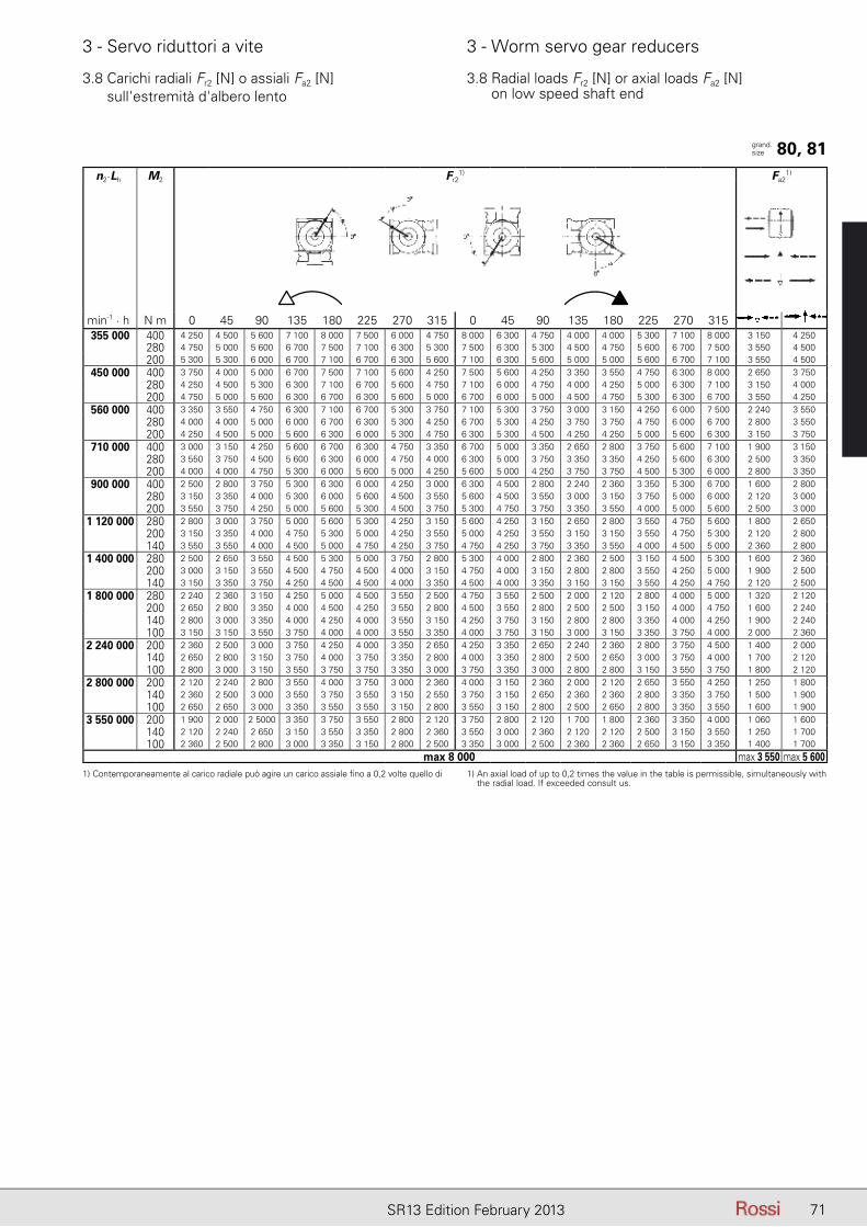
71SR13 Edition February 2013
3 - Servo riduttori a vite 3 - Worm servo gear reducers
3.8 Carichi radiali Fr2 [N] o assiali Fa2 [N] sull'estremità d'albero lento
3.8 Radial loads Fr2 [N] or axial loads Fa2 [N] on low speed shaft end
n2.Lh M2 Fr2
1) Fa21)
min-1 . h N m 0 45 90 135 180 225 270 315 0 45 90 135 180 225 270 315355 000 400 4 250 4 500 5 600 7 100 8 000 7 500 6 000 4 750 8 000 6 300 4 750 4 000 4 000 5 300 7 100 8 000 3 150 4 250
280 4 750 5 000 5 600 6 700 7 500 7 100 6 300 5 300 7 500 6 300 5 300 4 500 4 750 5 600 6 700 7 500 3 550 4 500200 5 300 5 300 6 000 6 700 7 100 6 700 6 300 5 600 7 100 6 300 5 600 5 000 5 000 5 600 6 700 7 100 3 550 4 500
450 000 400 3 750 4 000 5 000 6 700 7 500 7 100 5 600 4 250 7 500 5 600 4 250 3 350 3 550 4 750 6 300 8 000 2 650 3 750280 4 250 4 500 5 300 6 300 7 100 6 700 5 600 4 750 7 100 6 000 4 750 4 000 4 250 5 000 6 300 7 100 3 150 4 000200 4 750 5 000 5 600 6 300 6 700 6 300 5 600 5 000 6 700 6 000 5 000 4 500 4 750 5 300 6 300 6 700 3 550 4 250
560 000 400 3 350 3 550 4 750 6 300 7 100 6 700 5 300 3 750 7 100 5 300 3 750 3 000 3 150 4 250 6 000 7 500 2 240 3 550280 4 000 4 000 5 000 6 000 6 700 6 300 5 300 4 250 6 700 5 300 4 250 3 750 3 750 4 750 6 000 6 700 2 800 3 550200 4 250 4 500 5 000 5 600 6 300 6 000 5 300 4 750 6 300 5 300 4 500 4 250 4 250 5 000 5 600 6 300 3 150 3 750
710 000 400 3 000 3 150 4 250 5 600 6 700 6 300 4 750 3 350 6 700 5 000 3 350 2 650 2 800 3 750 5 600 7 100 1 900 3 150280 3 550 3 750 4 500 5 600 6 300 6 000 4 750 4 000 6 300 5 000 3 750 3 350 3 350 4 250 5 600 6 300 2 500 3 350200 4 000 4 000 4 750 5 300 6 000 5 600 5 000 4 250 5 600 5 000 4 250 3 750 3 750 4 500 5 300 6 000 2 800 3 350
900 000 400 2 500 2 800 3 750 5 300 6 300 6 000 4 250 3 000 6 300 4 500 2 800 2 240 2 360 3 350 5 300 6 700 1 600 2 800280 3 150 3 350 4 000 5 300 6 000 5 600 4 500 3 550 5 600 4 500 3 550 3 000 3 150 3 750 5 000 6 000 2 120 3 000200 3 550 3 750 4 250 5 000 5 600 5 300 4 500 3 750 5 300 4 750 3 750 3 350 3 550 4 000 5 000 5 600 2 500 3 000
1 120 000 280 2 800 3 000 3 750 5 000 5 600 5 300 4 250 3 150 5 600 4 250 3 150 2 650 2 800 3 550 4 750 5 600 1 800 2 650200 3 150 3 350 4 000 4 750 5 300 5 000 4 250 3 550 5 000 4 250 3 550 3 150 3 150 3 550 4 750 5 300 2 120 2 800140 3 550 3 550 4 000 4 500 5 000 4 750 4 250 3 750 4 750 4 250 3 750 3 350 3 550 4 000 4 500 5 000 2 360 2 800
1 400 000 280 2 500 2 650 3 550 4 500 5 300 5 000 3 750 2 800 5 300 4 000 2 800 2 360 2 500 3 150 4 500 5 300 1 600 2 360200 3 000 3 150 3 550 4 500 4 750 4 500 4 000 3 150 4 750 4 000 3 150 2 800 2 800 3 550 4 250 5 000 1 900 2 500140 3 150 3 350 3 750 4 250 4 500 4 500 4 000 3 350 4 500 4 000 3 350 3 150 3 150 3 550 4 250 4 750 2 120 2 500
1 800 000 280 2 240 2 360 3 150 4 250 5 000 4 500 3 550 2 500 4 750 3 550 2 500 2 000 2 120 2 800 4 000 5 000 1 320 2 120200 2 650 2 800 3 350 4 000 4 500 4 250 3 550 2 800 4 500 3 550 2 800 2 500 2 500 3 150 4 000 4 750 1 600 2 240140 2 800 3 000 3 350 4 000 4 250 4 000 3 550 3 150 4 250 3 750 3 150 2 800 2 800 3 350 4 000 4 250 1 900 2 240100 3 150 3 150 3 550 3 750 4 000 4 000 3 550 3 350 4 000 3 750 3 150 3 000 3 150 3 350 3 750 4 000 2 000 2 360
2 240 000 200 2 360 2 500 3 000 3 750 4 250 4 000 3 350 2 650 4 250 3 350 2 650 2 240 2 360 2 800 3 750 4 500 1 400 2 000140 2 650 2 800 3 150 3 750 4 000 3 750 3 350 2 800 4 000 3 350 2 800 2 500 2 650 3 000 3 750 4 000 1 700 2 120100 2 800 3 000 3 150 3 550 3 750 3 750 3 350 3 000 3 750 3 350 3 000 2 800 2 800 3 150 3 550 3 750 1 800 2 120
2 800 000 200 2 120 2 240 2 800 3 550 4 000 3 750 3 000 2 360 4 000 3 150 2 360 2 000 2 120 2 650 3 550 4 250 1 250 1 800140 2 360 2 500 3 000 3 550 3 750 3 550 3 150 2 550 3 750 3 150 2 650 2 360 2 360 2 800 3 350 3 750 1 500 1 900100 2 650 2 650 3 000 3 350 3 550 3 550 3 150 2 800 3 550 3 150 2 800 2 500 2 650 2 800 3 350 3 550 1 600 1 900
3 550 000 200 1 900 2 000 2 5000 3 350 3 750 3 550 2 800 2 120 3 750 2 800 2 120 1 700 1 800 2 360 3 350 4 000 1 060 1 600140 2 120 2 240 2 650 3 150 3 550 3 350 2 800 2 360 3 550 3 000 2 360 2 120 2 120 2 500 3 150 3 550 1 250 1 700100 2 360 2 500 2 800 3 000 3 350 3 150 2 800 2 500 3 350 3 000 2 500 2 360 2 360 2 650 3 150 3 350 1 400 1 700
max 8 000 max 3 550 max 5 6001) Contemporaneamente al carico radiale può agire un carico assiale fino a 0,2 volte quello di 1) An axial load of up to 0,2 times the value in the table is permissible, simultaneously with
the radial load. If exceeded consult us.
grand.size 80, 81

72 SR13 Edition February 2013
3 - Servo riduttori a vite 3 - Worm servo gear reducers
3.8 Carichi radiali Fr2 [N] o assiali Fa2 [N] sull'estremità d'albero lento
3.8 Radial loads Fr2 [N] or axial loads Fa2 [N] on low speed shaft end
n2.Lh M2 Fr2
1) Fa21)
min-1 . h N m 0 45 90 135 180 225 270 315 0 45 90 135 180 225 270 315335 000 800 5 000 5 600 7 100 9 500 11 200 10 600 8 000 6 000 11 200 8 000 5 600 4 500 5 000 6 300 9 500 11 800 3 550 5 600
560 6 000 6 300 7 500 9 500 10 000 9 500 8 000 6 700 10 000 8 500 6 700 5 600 6 000 7 100 9 000 10 600 4 500 5 600 400 6 700 6 700 8 000 9 000 9 500 9 500 8 000 7 100 9 500 8 500 7 100 6 300 6 700 7 500 9 000 10 000 5 000 6 000
450 000 800 4 500 4 750 6 300 9 000 10 600 9 500 7 100 5 300 10 600 7 500 5 000 4 000 4 250 5 600 8 500 11 200 3 000 4 750 560 5 300 5 600 7 100 8 500 9 500 9 000 7 500 6 000 9 500 7 500 6 000 5 000 5 300 6 700 8 500 10 000 3 750 5 300 400 6 000 6 300 7 100 8 500 9 000 8 500 7 500 6 300 9 000 7 500 6 300 5 600 6 000 6 700 8 500 9 000 4 250 5 300 280 6 300 6 700 7 100 8 000 8 500 8 500 7 500 6 700 8 500 7 500 6 700 6 300 6 300 7 100 8 000 8 500 4 750 5 600
560 000 800 4 000 4 250 6 000 8 500 9 500 9 000 6 700 4 750 10 000 6 700 4 500 3 550 3 750 5 300 8 000 10 600 2 500 4 500 560 4 750 5 300 6 300 8 000 9 000 8 500 7 100 5 600 9 000 7 100 5 300 4 500 4 750 6 000 8 000 9 500 3 350 4 750 400 5 600 5 600 6 700 8 000 8 500 8 000 7 100 6 000 8 500 7 100 6 000 5 300 5 300 6 300 7 500 8 500 4 000 4 750 280 6 000 6 000 6 700 7 500 8 000 8 000 7 100 6 300 8 000 7 100 6 300 5 600 6 000 6 700 7 500 8 000 4 250 5 000
710 000 560 4 250 4 500 5 600 7 500 8 500 8 000 6 300 5 000 8 500 6 700 4 750 4 000 4 250 5 300 7 500 9 000 2 800 4 250 400 5 000 5 300 6 000 7 100 8 000 7 500 6 300 5 300 8 000 6 700 5 300 4 750 4 750 5 600 7 100 8 000 3 350 4 250 280 5 300 5 600 6 300 7 100 7 500 7 100 6 300 5 600 7 500 6 700 5 600 5 300 5 300 6 000 7 100 7 500 3 750 4 500
900 000 560 3 750 4 000 5 300 7 100 8 000 7 500 5 600 4 500 8 000 6 000 4 250 3 550 3 750 4 750 6 700 8 500 2 500 3 750 400 4 500 4 750 5 600 6 700 7 500 7 100 6 000 5 000 7 500 6 000 4 750 4 250 4 250 5 300 6 700 7 500 3 000 4 000 280 5 000 5 000 5 600 6 700 7 100 6 700 6 000 5 300 7 100 6 000 5 300 4 750 4 750 5 600 6 300 7 100 3 350 4 000
1 120 000 560 3 350 3 750 4 750 6 700 7 500 7 100 5 300 4 000 7 500 5 600 3 750 3 150 3 150 4 500 6 300 8 000 2 120 3 350 400 4 000 4 250 5 000 6 300 7 100 6 700 5 600 4 500 7 100 5 600 4 500 3 750 4 000 4 750 6 300 7 100 2 650 3 550 280 4 500 4 750 5 300 6 000 6 700 6 300 5 600 4 750 6 700 5 600 4 750 4 250 4 500 5 000 6 000 6 700 3 000 3 750
1 400 000 560 3 000 3 350 4 500 6 300 7 100 6 700 5 000 3 550 7 100 5 000 3 350 2 650 2 800 4 000 6 000 7 500 1 700 3 000 400 3 550 3 750 4 750 6 000 6 700 6 300 5 000 4 000 6 700 5 300 4 000 3 350 3 550 4 500 6 000 6 700 2 240 3 150 280 4 000 4 250 5 000 5 600 6 300 6 000 5 300 4 500 6 300 5 300 4 500 4 000 4 000 4 750 5 600 6 300 2 650 3 350
1 800 000 560 2 650 2 800 4 000 5 600 6 300 6 000 4 500 3 150 6 700 4 750 3 000 2 240 2 360 3 550 5 600 7 100 1 400 2 650 400 3 150 3 350 4 250 5 600 6 300 6 000 4 750 3 550 6 300 4 750 3 550 3 000 3 150 4 000 5 300 6 300 1 900 2 800 280 3 750 3 750 4 500 5 300 5 600 5 600 4 750 4 000 5 600 5 000 4 000 3 550 3 550 4 250 5 300 6 000 2 360 3 000
2 240 000 400 2 800 3 150 4 000 5 300 6 000 5 600 4 250 3 350 5 600 4 500 3 150 2 650 2 800 3 550 5 000 6 000 1 700 2 650 280 3 350 3 550 4 000 5 000 5 600 5 300 4 500 3 750 5 300 4 500 3 550 3 150 3 350 4 000 5 000 5 600 2 000 2 650
2 800 000 400 2 500 2 800 3 550 4 750 5 600 5 300 4 000 3 000 5 600 4 000 2 800 2 360 2 500 3 350 4 750 5 600 1 400 2 350 280 3 000 3 150 3 750 4 750 5 000 5 000 4 000 3 350 5 000 4 250 3 350 2 800 3 000 3 550 4 500 5 300 1 800 2 550
3 550 000 400 2 240 2 500 3 150 4 500 5 300 5 000 3 550 2 650 5 300 3 750 2 500 2 000 2 120 3 000 4 500 5 600 1 180 2 120 280 2 650 2 800 3 550 4 250 4 750 4 500 3 750 3 000 4 750 3 750 3 000 2 500 2 650 3 350 4 250 5 000 1 500 2 240
max 11 200 max 5 000 max 6 000
grand.size 100
1) Contemporaneamente al carico radiale può agire un carico assiale fino a 0,2 volte quello di tabella e viceversa. Per valori superiori interpellarci.
1) An axial load of up to 0,2 times the value in the table is permissible, simultaneously with the radial load. If exceeded consult us.
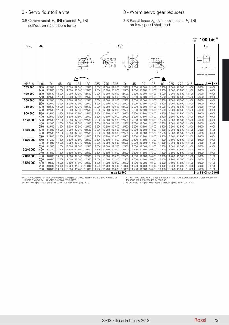
73SR13 Edition February 2013
3 - Servo riduttori a vite 3 - Worm servo gear reducers
3.8 Carichi radiali Fr2 [N] o assiali Fa2 [N] sull'estremità d'albero lento
3.8 Radial loads Fr2 [N] or axial loads Fa2 [N] on low speed shaft end
n2.Lh M2 Fr2
1) Fa21)
min-1 . h N m 0 45 90 135 180 225 270 315 0 45 90 135 180 225 270 315355 000 800 12 500 12 500 12 500 12 500 12 500 12 500 12 500 12 500 12 500 12 500 12 500 12 500 12 500 12 500 12 500 12 500 5 600 9 000
560 12 500 12 500 12 500 12 500 12 500 12 500 12 500 12 500 12 500 12 500 12 500 12 500 12 500 12 500 12 500 12 500 5 600 9 000
450 000 800 12 500 12 500 12 500 12 500 12 500 12 500 12 500 12 500 12 500 12 500 12 500 12 500 12 500 12 500 12 500 12 500 5 600 9 000 560 12 500 12 500 12 500 12 500 12 500 12 500 12 500 12 500 12 500 12 500 12 500 12 500 12 500 12 500 12 500 12 500 5 600 9 000
560 000 800 12 500 12 500 12 500 12 500 12 500 12 500 12 500 12 500 12 500 12 500 12 500 12 500 12 500 12 500 12 500 12 500 5 600 9 000 560 12 500 12 500 12 500 12 500 12 500 12 500 12 500 12 500 12 500 12 500 12 500 12 500 12 500 12 500 12 500 12 500 5 600 9 000
710 000 560 12 500 12 500 12 500 12 500 12 500 12 500 12 500 12 500 12 500 12 500 12 500 12 500 12 500 12 500 12 500 12 500 5 600 9 000 400 12 500 12 500 12 500 12 500 12 500 12 500 12 500 12 500 12 500 12 500 12 500 12 500 12 500 12 500 12 500 12 500 5 600 9 000
900 000 560 12 500 12 500 12 500 12 500 12 500 12 500 12 500 12 500 12 500 12 500 12 500 12 500 12 500 12 500 12 500 12 500 5 600 9 000 400 12 500 12 500 12 500 12 500 12 500 12 500 12 500 12 500 12 500 12 500 12 500 12 500 12 500 12 500 12 500 12 500 5 600 9 000
1 120 000 560 12 500 12 500 12 500 12 500 12 500 12 500 12 500 12 500 12 500 12 500 12 500 12 500 12 500 12 500 12 500 12 500 5 600 9 000 400 12 500 12 500 12 500 12 500 12 500 12 500 12 500 12 500 12 500 12 500 12 500 12 500 12 500 12 500 12 500 12 500 5 600 9 000 280 12 500 12 500 12 500 12 500 12 500 12 500 12 500 12 500 12 500 12 500 12 500 12 500 12 500 12 500 12 500 12 500 5 600 9 000
1 400 000 560 11 800 12 500 12 500 12 500 12 500 12 500 12 500 12 500 12 500 12 500 12 500 11 800 11 800 12 500 12 500 12 500 5 600 8 500 400 12 500 12 500 12 500 12 500 12 500 12 500 12 500 12 500 12 500 12 500 12 500 12 500 12 500 12 500 12 500 12 500 5 600 9 000 280 12 500 12 500 12 500 12 500 12 500 12 500 12 500 12 500 12 500 12 500 12 500 12 500 12 500 12 500 12 500 12 500 5 600 9 000
1 800 000 560 11 200 11 800 12 500 12 500 12 500 12 500 12 500 11 800 12 500 12 500 11 800 11 200 11 200 12 500 12 500 12 500 5 600 8 000 400 11 800 12 500 12 500 12 500 12 500 12 500 12 500 12 500 12 500 12 500 12 500 11 800 11 800 12 500 12 500 12 500 5 600 8 500 280 12 500 12 500 12 500 12 500 12 500 12 500 12 500 12 500 12 500 12 500 12 500 12 500 12 500 12 500 12 500 12 500 5 600 8 500
2 240 000 400 11 200 11 200 12 500 12 500 12 500 12 500 12 500 11 800 12 500 12 500 11 800 10 600 11 200 11 800 12 500 12 500 5 600 7 500 280 11 800 11 800 12 500 12 500 12 500 12 500 12 500 11 800 12 500 12 500 11 800 11 200 11 800 12 500 12 500 12 500 5 600 8 000
2 800 000 400 10 600 10 600 11 800 12 500 12 500 12 500 11 800 10 600 12 500 11 800 10 600 10 000 10 000 11 200 12 500 12 500 5 600 7 100 280 10 600 11 200 11 800 12 500 12 500 12 500 11 800 11 200 12 500 11 800 11 200 10 600 10 600 11 200 12 500 12 500 5 600 7 500
3 550 000 400 9 500 10 000 10 600 11 800 12 500 11 800 11 200 10 000 12 500 11 200 10 000 9 500 9 500 10 600 11 800 12 500 5 600 6 700 280 10 000 10 000 10 600 11 800 11 800 11 800 11 200 10 000 11 800 11 200 10 000 10 000 10 000 10 600 11 800 11 800 5 600 6 700 200 10 000 10 600 10 600 11 200 11 800 11 200 11 200 10 600 11 800 11 200 10 600 10 000 10 000 10 600 11 200 11 800 5 600 7 100
max 12 500 max 5 600 max 9 000
1) Contemporaneamente al carico radiale può agire un carico assiale fino a 0,2 volte quello di tabella e viceversa. Per valori superiori interpellarci.
2) Valori validi per cuscinetti a rulli conici sull'asse lento (cap. 3.10).
1) An axial load of up to 0,2 times the value in the table is permissible, simultaneously with the radial load. If exceeded consult us.
2) Values valid for taper roller bearing on low speed shaft (ch. 3.10).
grand.size 100 bis2)
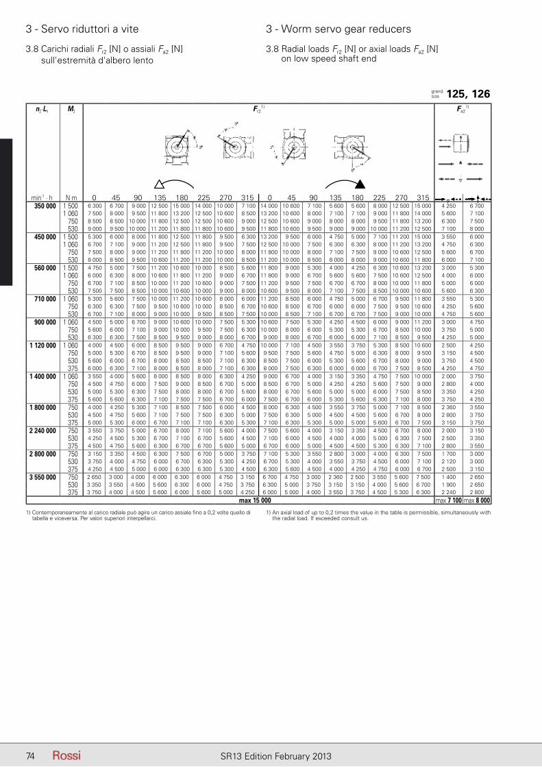
74 SR13 Edition February 2013
3 - Servo riduttori a vite 3 - Worm servo gear reducers
n2.Lh M2 Fr2
1) Fa21)
min-1 . h N m 0 45 90 135 180 225 270 315 0 45 90 135 180 225 270 315350 000 1 500 6 300 6 700 9 000 12 500 15 000 14 000 10 000 7 100 14 000 10 600 7 100 5 600 5 600 8 000 12 500 15 000 4 250 6 700
1 060 7 500 8 000 9 500 11 800 13 200 12 500 10 600 8 500 13 200 10 600 8 000 7 100 7 100 9 000 11 800 14 000 5 600 7 100 750 8 500 8 500 10 000 11 800 12 500 12 500 10 600 9 000 12 500 10 600 9 000 8 000 8 000 9 500 11 800 13 200 6 300 7 500 530 9 000 9 500 10 000 11 200 11 800 11 800 10 600 9 500 11 800 10 600 9 500 9 000 9 000 10 000 11 200 12 500 7 100 8 000
450 000 1 500 5 300 6 000 8 000 11 800 12 500 11 800 9 500 6 300 13 200 9 500 6 000 4 750 5 000 7 100 11 200 15 000 3 550 6 0001 060 6 700 7 100 9 000 11 200 12 500 11 800 9 500 7 500 12 500 10 000 7 500 6 300 6 300 8 000 11 200 13 200 4 750 6 300
750 7 500 8 000 9 000 11 200 11 800 11 200 10 000 8 000 11 800 10 000 8 000 7 100 7 500 9 000 10 600 12 500 5 600 6 700 530 8 000 8 500 9 500 10 600 11 200 11 200 10 000 8 500 11 200 10 000 8 500 8 000 8 000 9 000 10 600 11 800 6 000 7 100
560 000 1 500 4 750 5 000 7 500 11 200 10 600 10 000 8 500 5 600 11 800 9 000 5 300 4 000 4 250 6 300 10 600 13 200 3 000 5 3001 060 6 000 6 300 8 000 10 600 11 800 11 200 9 000 6 700 11 800 9 000 6 700 5 600 5 600 7 500 10 600 12 500 4 000 6 000
750 6 700 7 100 8 500 10 000 11 200 10 600 9 000 7 500 11 200 9 500 7 500 6 700 6 700 8 000 10 000 11 800 5 000 6 000 530 7 500 7 500 8 500 10 000 10 600 10 000 9 000 8 000 10 600 9 500 8 000 7 100 7 500 8 500 10 000 10 600 5 600 6 300
710 000 1 060 5 300 5 600 7 500 10 000 11 200 10 600 8 000 6 000 11 200 8 500 6 000 4 750 5 000 6 700 9 500 11 800 3 550 5 300 750 6 300 6 300 7 500 9 500 10 600 10 000 8 500 6 700 10 600 8 500 6 700 6 000 6 000 7 500 9 500 10 600 4 250 5 600 530 6 700 7 100 8 000 9 000 10 000 9 500 8 500 7 500 10 000 8 500 7 100 6 700 6 700 7 500 9 000 10 000 4 750 5 600
900 000 1 060 4 500 5 000 6 700 9 000 10 600 10 000 7 500 5 300 10 600 7 500 5 300 4 250 4 500 6 000 9 000 11 200 3 000 4 750 750 5 600 6 000 7 100 9 000 10 000 9 500 7 500 6 300 10 000 8 000 6 000 5 300 5 300 6 700 8 500 10 000 3 750 5 000 530 6 300 6 300 7 500 8 500 9 500 9 000 8 000 6 700 9 000 8 000 6 700 6 000 6 000 7 100 8 500 9 500 4 250 5 000
1 120 000 1 060 4 000 4 500 6 000 8 500 9 500 9 000 6 700 4 750 10 000 7 100 4 500 3 550 3 750 5 300 8 500 10 600 2 500 4 250 750 5 000 5 300 6 700 8 500 9 500 9 000 7 100 5 600 9 500 7 500 5 600 4 750 5 000 6 300 8 000 9 500 3 150 4 500 530 5 600 6 000 6 700 8 000 8 500 8 500 7 100 6 300 8 500 7 500 6 000 5 300 5 600 6 700 8 000 9 000 3 750 4 500 375 6 000 6 300 7 100 8 000 8 500 8 000 7 100 6 300 8 000 7 500 6 300 6 000 6 000 6 700 7 500 8 500 4 250 4 750
1 400 000 1 060 3 550 4 000 5 600 8 000 8 500 8 000 6 300 4 250 9 000 6 700 4 000 3 150 3 350 4 750 7 500 10 000 2 000 3 750 750 4 500 4 750 6 000 7 500 9 000 8 500 6 700 5 000 8 500 6 700 5 000 4 250 4 250 5 600 7 500 9 000 2 800 4 000 530 5 000 5 300 6 300 7 500 8 000 8 000 6 700 5 600 8 000 6 700 5 600 5 000 5 000 6 000 7 500 8 500 3 350 4 250 375 5 600 5 600 6 300 7 100 7 500 7 500 6 700 6 000 7 500 6 700 6 000 5 300 5 600 6 300 7 100 8 000 3 750 4 250
1 800 000 750 4 000 4 250 5 300 7 100 8 500 7 500 6 000 4 500 8 000 6 300 4 500 3 550 3 750 5 000 7 100 8 500 2 360 3 550 530 4 500 4 750 5 600 7 100 7 500 7 500 6 300 5 000 7 500 6 300 5 000 4 500 4 500 5 600 6 700 8 000 2 800 3 750 375 5 000 5 300 6 000 6 700 7 100 7 100 6 300 5 300 7 100 6 300 5 300 5 000 5 000 5 600 6 700 7 500 3 150 3 750
2 240 000 750 3 550 3 750 5 000 6 700 8 000 7 100 5 600 4 000 7 500 5 600 4 000 3 150 3 350 4 500 6 700 8 000 2 000 3 150 530 4 250 4 500 5 300 6 700 7 100 6 700 5 600 4 500 7 100 6 000 4 500 4 000 4 000 5 000 6 300 7 500 2 500 3 350 375 4 500 4 750 5 600 6 300 6 700 6 700 5 600 5 000 6 700 6 000 5 000 4 500 4 500 5 300 6 300 7 100 2 800 3 550
2 800 000 750 3 150 3 350 4 500 6 300 7 500 6 700 5 000 3 750 7 100 5 300 3 550 2 800 3 000 4 000 6 300 7 500 1 700 3 000 530 3 750 4 000 4 750 6 000 6 700 6 300 5 300 4 250 6 700 5 300 4 000 3 550 3 750 4 500 6 000 7 100 2 120 3 000 375 4 250 4 500 5 000 6 000 6 300 6 300 5 300 4 500 6 300 5 600 4 500 4 000 4 250 4 750 6 000 6 700 2 500 3 150
3 550 000 750 2 650 3 000 4 000 6 000 6 300 6 000 4 750 3 150 6 700 4 750 3 000 2 360 2 500 3 550 5 600 7 500 1 400 2 650 530 3 350 3 550 4 500 5 600 6 300 6 000 4 750 3 750 6 300 5 000 3 750 3 150 3 150 4 000 5 600 6 700 1 900 2 650 375 3 750 4 000 4 500 5 600 6 000 5 600 5 000 4 250 6 000 5 000 4 000 3 550 3 750 4 500 5 300 6 300 2 240 2 800
max 15 000 max 7 100 max 8 000
3.8 Carichi radiali Fr2 [N] o assiali Fa2 [N] sull'estremità d'albero lento
3.8 Radial loads Fr2 [N] or axial loads Fa2 [N] on low speed shaft end
grand.size 125, 126
1) Contemporaneamente al carico radiale può agire un carico assiale fino a 0,2 volte quello di tabella e viceversa. Per valori superiori interpellarci.
1) An axial load of up to 0,2 times the value in the table is permissible, simultaneously with the radial load. If exceeded consult us.

75SR13 Edition February 2013
3 - Servo riduttori a vite 3 - Worm servo gear reducers
n2.Lh M2 Fr2
1) Fa21)
min-1 . h N m 0 45 90 135 180 225 270 315 0 45 90 135 180 225 270 315355 000 1 500 20 000 20 000 20 000 20 000 20 000 20 000 20 000 20 000 20 000 20 000 20 000 20 000 20 000 20 000 20 000 20 000 9 000 14 000
1 060 20 000 20 000 20 000 20 000 20 000 20 000 20 000 20 000 20 000 20 000 20 000 20 000 20 000 20 000 20 000 20 000 9 000 14 000
450 000 1 500 20 000 20 000 20 000 20 000 20 000 20 000 20 000 20 000 20 000 20 000 20 000 20 000 20 000 20 000 20 000 20 000 9 000 14 0001 060 20 000 20 000 20 000 20 000 20 000 20 000 20 000 20 000 20 000 20 000 20 000 20 000 20 000 20 000 20 000 20 000 9 000 14 000
560 000 1 500 20 000 20 000 20 000 20 000 20 000 20 000 20 000 20 000 20 000 20 000 20 000 20 000 20 000 20 000 20 000 20 000 9 000 14 0001 060 20 000 20 000 20 000 20 000 20 000 20 000 20 000 20 000 20 000 20 000 20 000 20 000 20 000 20 000 20 000 20 000 9 000 14 000
750 20 000 20 000 20 000 20 000 20 000 20 000 20 000 20 000 20 000 20 000 20 000 20 000 20 000 20 000 20 000 20 000 9 000 14 000
710 000 1 500 20 000 20 000 20 000 20 000 20 000 20 000 20 000 20 000 20 000 20 000 20 000 20 000 20 000 20 000 20 000 20 000 9 000 14 0001 060 20 000 20 000 20 000 20 000 20 000 20 000 20 000 20 000 20 000 20 000 20 000 20 000 20 000 20 000 20 000 20 000 9 000 14 000
750 20 000 20 000 20 000 20 000 20 000 20 000 20 000 20 000 20 000 20 000 20 000 20 000 20 000 20 000 20 000 20 000 9 000 14 000 530 20 000 20 000 20 000 20 000 20 000 20 000 20 000 20 000 20 000 20 000 20 000 20 000 20 000 20 000 20 000 20 000 9 000 14 000
900 000 1 060 19 000 20 000 20 000 20 000 20 000 20 000 20 000 20 000 20 000 20 000 20 000 19 000 19 000 20 000 20 000 20 000 9 000 14 000 750 20 000 20 000 20 000 20 000 20 000 20 000 20 000 20 000 20 000 20 000 20 000 20 000 20 000 20 000 20 000 20 000 9 000 14 000 530 20 000 20 000 20 000 20 000 20 000 20 000 20 000 20 000 20 000 20 000 20 000 20 000 20 000 20 000 20 000 20 000 9 000 14 000
1 120 000 1 060 18 000 19 000 20 000 20 000 20 000 20 000 20 000 19 000 20 000 20 000 19 000 18 000 18 000 20 000 20 000 20 000 9 000 13 200 750 19 000 19 000 20 000 20 000 20 000 20 000 20 000 20 000 20 000 20 000 20 000 19 000 19 000 20 000 20 000 20 000 9 000 14 000
530 20 000 20 000 20 000 20 000 20 000 20 000 20 000 20 000 20 000 20 000 20 000 19 000 20 000 20 000 20 000 20 000 9 000 14 000 375 20 000 20 000 20 000 20 000 20 000 20 000 20 000 20 000 20 000 20 000 20 000 20 000 20 000 20 000 20 000 20 000 9 000 14 000
1 400 000 1 060 17 000 17 000 19 000 20 000 20 000 20 000 20 000 18 000 20 000 20 000 18 000 16 000 17 000 18 000 20 000 20 000 9 000 12 500 750 17 000 18 000 19 000 20 000 20 000 20 000 20 000 18 000 20 000 20 000 18 000 17 000 17 000 19 000 20 000 20 000 9 000 13 200
530 18 000 18 000 19 000 20 000 20 000 20 000 20 000 19 000 20 000 20 000 19 000 18 000 18 000 19 000 20 000 20 000 9 000 13 200 375 18 000 19 000 20 000 20 000 20 000 20 000 20 000 19 000 20 000 20 000 19 000 18 000 18 000 19 000 20 000 20 000 9 000 13 200
1 800 000 1 060 15 000 16 000 18 000 20 000 20 000 20 000 18 000 16 000 20 000 18 000 16 000 15 000 15 000 17 000 20 000 20 000 9 000 11 800 750 16 000 16 000 18 000 19 000 20 000 20 000 18 000 17 000 20 000 18 000 17 000 16 000 16 000 17 000 19 000 20 000 9 000 11 800 530 17 000 17 000 18 000 19 000 20 000 19 000 18 000 17 000 20 000 18 000 17 000 16 000 17 000 18 000 19 000 20 000 9 000 12 500 375 17 000 17 000 18 000 19 000 19 000 19 000 18 000 17 000 19 000 18 000 17 000 17 000 17 000 18 000 19 000 19 000 9 000 12 500
2 240 000 750 16 000 16 000 18 000 19 000 20 000 19 000 18 000 16 000 20 000 18 000 16 000 15 000 16 000 17 000 19 000 20 000 9 000 11 200 530 16 000 17 000 18 000 19 000 19 000 19 000 18 000 17 000 19 000 18 000 17 000 16 000 16 000 17 000 19 000 19 000 9 000 11 800 375 17 000 17 000 18 000 18 000 19 000 19 000 18 000 17 000 19 000 18 000 17 000 17 000 17 000 18 000 18 000 19 000 9 000 11 800
2 800 000 750 15 000 15 000 16 000 18 000 19 000 18 000 17 000 15 000 19 000 17 000 15 000 14 000 15 000 16 000 18 000 19 000 9 000 10 600 530 15 000 16 000 17 000 18 000 18 000 18 000 17 000 16 000 18 000 17 000 16 000 15 000 15 000 16 000 18 000 18 000 9 000 10 600 375 16 000 16 000 17 000 17 000 18 000 17 000 17 000 16 000 18 000 17 000 16 000 16 000 16 000 16 000 17 000 18 000 9 000 11 200
3 550 000 750 13 200 14 000 15 000 17 000 18 000 17 000 16 000 14 000 18 000 16 000 14 000 13 200 13 200 15 000 17 000 18 000 8 500 10 000 530 14 000 14 000 15 000 16 000 17 000 17 000 16 000 15 000 17 000 16 000 15 000 14 000 14 000 15 000 16 000 17 000 9 000 10 000 375 15 000 15 000 15 000 16 000 17 000 16 000 16 000 15 000 17 000 16 000 15 000 14 000 15 000 15 000 16 000 17 000 9 000 10 000
max 20 000 max 9 000 max 14 000
3.8 Carichi radiali Fr2 [N] o assiali Fa2 [N] sull'estremità d'albero lento
3.8 Radial loads Fr2 [N] or axial loads Fa2 [N] on low speed shaft end
grand.size 125 bis2)
, 126 bis2)
1) Contemporaneamente al carico radiale può agire un carico assiale fino a 0,2 volte quello di tabella e viceversa. Per valori superiori interpellarci.
2) Valori validi per cuscinetti a rulli conici sull'asse lento (cap. 3.10).
1) An axial load of up to 0,2 times the value in the table is permissible, simultaneously with the radial load. If exceeded consult us.
2) Values valid for taper roller bearing on low speed shaft (ch. 3.10).
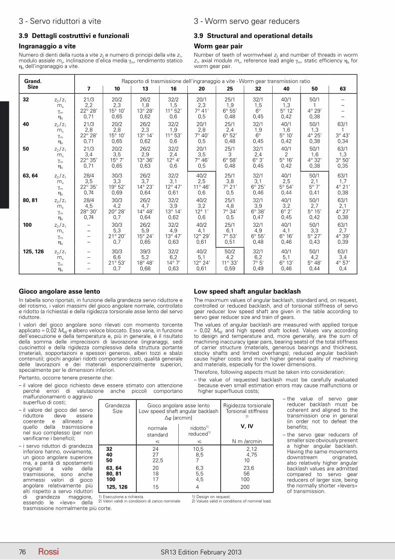
76 SR13 Edition February 2013
3 - Servo riduttori a vite 3 - Worm servo gear reducers
Grand. Size
Rapporto di trasmissione dell'ingranaggio a vite - Worm gear transmission ratio7 10 13 16 20 25 32 40 50 63
32 z2 / z1 21/3 20/2 26/2 32/2 20/1 25/1 32/1 40/1 50/1 –mx 2,2 2,3 1,8 1,5 2,3 1,9 1,5 1,3 1 –γm 22° 28’ 15° 10’ 13° 28’ 11° 52’ 7° 41’ 6° 55’ 6° 5° 12’ 4° 29’ –ηs 0,71 0,65 0,62 0,6 0,5 0,48 0,45 0,42 0,38 –
40 z2 / z1 21/3 20/2 26/2 32/2 20/1 25/1 32/1 40/1 50/1 63/1mx 2,8 2,8 2,3 1,9 2,8 2,4 1,9 1,6 1,3 1γm 22° 28’ 15° 10’ 13° 14’ 11° 53’ 7° 40’ 6° 52’ 6° 5° 10’ 4° 25’ 3° 43’ηs 0,71 0,65 0,62 0,6 0,5 0,48 0,45 0,42 0,38 0,34
50 z2 / z1 21/3 20/2 26/2 32/2 20/1 25/1 32/1 40/1 50/1 63/1mx 3,4 3,5 2,9 2,4 3,5 3 2,4 2 1,6 1,3γm 22° 35’ 15° 7’ 13° 36’ 12° 4’ 7° 46’ 6° 58’ 6° 3’ 5° 16’ 4° 32’ 3° 50’ηs 0,71 0,65 0,63 0,6 0,5 0,48 0,45 0,42 0,38 0,35
63, 64 z2 / z1 28/4 30/3 26/2 32/2 40/2 25/1 32/1 40/1 50/1 63/1mx 3,5 3,3 3,7 3,1 2,5 3,8 3,1 2,5 2,1 1,7γm 22° 35’ 19° 52’ 14° 23’ 12° 47’ 11° 46’ 7° 21’ 6° 25’ 5° 54’ 5° 7’ 4° 21’ηs 0,74 0,69 0,64 0,61 0,6 0,5 0,46 0,44 0,41 0,38
80, 81 z2 / z1 28/4 30/3 26/2 32/2 40/2 25/1 32/1 40/1 50/1 63/1mx 4,5 4,2 4,7 3,9 3,2 4,8 3,9 3,2 2,7 2,1γm 28° 30’ 20° 28’ 14° 48’ 13° 14’ 12° 1’ 7° 34’ 6° 38’ 6° 2’ 5° 15’ 4° 27’ηs 0,74 0,7 0,64 0,62 0,6 0,5 0,47 0,45 0,42 0,38
100 z2 / z1 – 30/3 26/2 32/2 40/2 25/1 32/1 40/1 50/1 63/1mx – 5,3 5,9 4,9 4,1 6,1 4,9 4,1 3,3 2,7γm – 21° 20’ 15° 24’ 13° 47’ 12° 29’ 7° 53’ 6° 55’ 6° 16’ 5° 27’ 4° 39’ηs – 0,7 0,65 0,63 0,61 0,51 0,48 0,46 0,43 0,39
125, 126 z2 / z1 – 30/3 39/3 32/2 40/2 50/2 32/1 40/1 50/1 63/1mx – 6,6 5,2 6,2 5,1 4,2 6,2 5,1 4,2 3,4γm – 21° 53’ 18° 48’ 14° 7’ 12° 24’ 11° 33’ 7° 5’ 6° 13’ 5° 48’ 4° 57’ηs – 0,7 0,68 0,63 0,61 0,59 0,49 0,46 0,44 0,4
3.9 Dettagli costruttivi e funzionali 3.9 Structural and operational details
Ingranaggio a viteNumero di denti della ruota a vite z2 e numero di principi della vite z1, modulo assiale mx, inclinazione d’elica media γm, rendimento statico ηs dell’ingranaggio a vite.
Worm gear pairNumber of teeth of wormwheel z2 and number of threads in worm z1, axial module mx, reference lead angle γm, static efficiency ηs for worm gear pair.
Gioco angolare asse lentoIn tabella sono riportati, in funzione della grandezza servo riduttore e del rotismo, i valori massimi del gioco angolare normale, controllato e ridotto (a richiesta) e della rigidezza torsionale asse lento del servo riduttore.I valori del gioco angolare sono rilevati con momento torcente applicato ≈ 0,02 MN2 e albero veloce bloccato. Esso varia, in funzione dell’esecuzione e della temperatura e, più in generale, è il risultato della somma delle imprecisioni di lavorazione (ingranaggi, sedi cuscinetto) e della rigidezza complessiva della struttura portante (materiali, sopportazioni e spessori generosi, alberi tozzi e sbalzi contenuti); giochi angolari ridotti comportano costi, qualità generale delle lavorazioni e dei materiali esponenzialmente superiori, specialmente per le dimensioni inferiori.Pertanto, occorre tenere presente che:– il valore del gioco richiesto deve essere stimato con attenzione
perché errori di valutazione anche piccoli comportano malfunzionamenti o aggravio superfluo di costi;
– il valore del gioco del servo riduttore deve essere coerente e allineato a quello della trasmissione nel suo complesso (per non vanificarne i benefici);
– i servo riduttori di grandezza inferiore hanno, ovviamente, un gioco angolare superiore ma, a parità di spostamenti originati a valle della trasmissione, sono anche ammessi valori di gioco angolare relativamente più alti rispetto a servo riduttori di grandezza maggiore, essendo le «leve» della trasmissione normalmente più corte.
Low speed shaft angular backlashThe maximum values of angular backlash, standard and, on request, controlled or reduced backlash, and of torsional stiffness of servo gear reducer low speed shaft are given in the table according to servo gear reducer size and train of gears.The values of angular backlash are measured with applied torque ≈ 0,02 MN2 and high speed shaft locked. Values vary according to design and temperature and, more generally, are the sum of machining inaccuracy (gear pairs, bearing seats) of the total stiffness of carrier structure (materials, generous bearings and thickness, stocky shafts and limited overhangs); reduced angular backlash cause higher costs and much higher general quality of machining and materials, especially for the lower dimensions.Therefore, following aspects must be taken into consideration:– the value of requested backlash must be carefully evaluated
because even small estimation errors may cause malfunctions or higher superfluous costs;
– the value of servo gear reducer backlash must be coherent and aligned to the transmission one in general (in order not to defeat the benefits;
– the servo gear reducers of smaller size obviously present a higher angular backlash. Having the same movements downstream originated, also relatively higher angular backlash values are admitted compared to servo gear reducers of larger size, being the normally shorter «levers» of transmission.
GrandezzaSize
Gioco angolare asse lentoLow speed shaft angular backlash
∆� [arcmin]
Rigidezza torsionaleTorsional stiffness
2)
normalestandard
ridotto1)
reduced1)
V, IV
� � N m /arcmin32, 00 24 10,5 2,1240, 00 27 8,5 4,7550, 00 22,5 7 1063, 64 20 6,3 23,680, 81 18 5,5 56100 17 4,5 100125, 126 15 4 200
1) Esecuzione a richiesta.2) Valori validi in condizioni di carico nominale
1) Design on request.2) Values valid in conditions of nominal load.
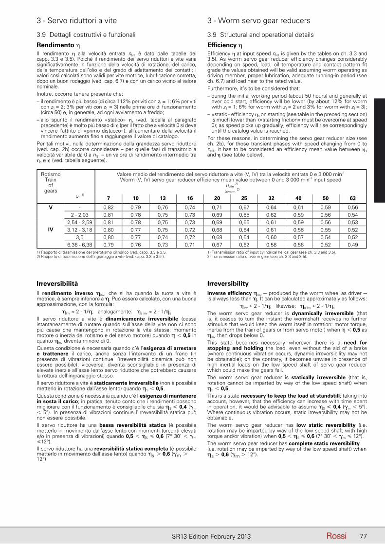
77SR13 Edition February 2013
3 - Servo riduttori a vite 3 - Worm servo gear reducers
Rendimento ηIl rendimento η alla velocità entrata nN1 è dato dalle tabelle dei capp. 3.3 e 3.5). Poiché il rendimento dei servo riduttori a vite varia significativamente in funzione della velocità di rotazione, del carico, della temperatura dell’olio e del grado di adattamento dei contatti; i valori così calcolati sono validi per vite motrice, lubrificazione corretta, dopo un buon rodaggio (ved. cap. 6.7) e con un carico vicino al valore nominale.Inoltre, occorre tenere presente che:– il rendimento è più basso (di circa il 12% per viti con z1 = 1; 6% per viti
con z1 = 2; 3% per viti con z1 = 3) nelle prime ore di funzionamento (circa 50) e, in generale, ad ogni avviamento a freddo;
– allo spunto il rendimento «statico» ηs (ved. tabella al paragrafo precedente) è molto più basso di η (per il fatto che a velocità 0 si deve vincere l’attrito di «primo distacco»); all’aumentare della velocità il rendimento aumenta fino a raggiungere il valore di catalogo.
Per tali motivi, nella determinazione della grandezza servo riduttore (ved. cap. 2b) occorre considerare – per quelle fasi di transitorio a velocità variabile da 0 a nN1 – un valore di rendimento intermedio tra ηs e η (ved. tabella seguente).
Efficiency ηEfficiency η at input speed nN1 is given by the tables on ch. 3.3 and 3.5). As worm servo gear reducer efficiency changes considerably depending on speed, load, oil temperature and contact pattern fit grade the values obtained will be valid assuming worm operating as driving member, proper lubrication, adequate running-in period (see ch. 6.7) and load near to the rated value.Furthermore, it’s to be considered that:– during the initial working period (about 50 hours) and generally at
ever cold start, efficiency will be lower (by about 12% for worm with z1 = 1; 6% for worm with z1 = 2 and 3% for worm with z1 = 3);
– «static» efficiency ηs on starting (see table in the preceding section) is much lower than («starting friction» must be overcome at speed 0); as speed picks up gradually, efficiency will rise correspondingly until the catalog value is reached.
For these reasons, in determining the servo gear reducer size (see ch. 2b), for those transient phases with speed changing from 0 to nN1, it has to be considered an efficiency mean value between ηs and η (see table below).
3.9 Dettagli costruttivi e funzionali 3.9 Structural and operational details
RotismoTrain
ofgears
u1 1)
Valore medio del rendimento del servo riduttore a vite (V, IV) tra la velocità entrata 0 e 3 000 min-1
Worm (V, IV) servo gear reducer effi ciency mean value between 0 and 3 000 min-1 input speed
7 10 13 16 20 25 32 40 50 63
V - 0,82 0,79 0,76 0,74 0,71 0,67 0,64 0,61 0,59 0,56
IV
2 - 2,03 0,81 0,78 0,75 0,73 0,69 0,65 0,62 0,59 0,56 0,542,54 - 2,59 0,81 0,78 0,75 0,73 0,69 0,65 0,61 0,59 0,56 0,533,12 - 3,18 0,80 0,77 0,75 0,72 0,68 0,64 0,61 0,58 0,55 0,52
3,5 0,80 0,77 0,74 0,72 0,68 0,64 0,60 0,57 0,54 0,526,36 - 6,38 0,79 0,76 0,73 0,71 0,67 0,62 0,58 0,56 0,52 0,49
1) Rapporto di trasmissione del prerotismo cilindrico (ved. capp. 3.3 e 3.5.2) Rapporto di trasmissione dell'ingranaggio a vite (ved. capp. 3.3 e 3.5 ).
1) Transmission ratio of input cylindrical helical gear (see ch. 3.3 and 3.5).2) Transmission ratio of worm gear (see ch. 3.3 and 3.5).
IrreversibilityInverse efficiency �inv – produced by the worm wheel as driver – is always less than �. It can be calculated approximately as follows:
�inv ≈ 2 - 1/�; likewise: �s inv ≈ 2 - 1/�s
The worm servo gear reducer is dynamically irreversible (that is, it ceases to turn the instant the wormshaft receives no further stimulus that would keep the worm itself in rotation: motor torque, inertia from the train of gears or from servo motor) when � � 0,5 as �inv then drops below 0.This state becomes necessary wherever there is a need for stopping and holding the load, even without the aid of a brake (where continuous vibration occurs, dynamic irreversibility may not be obtainable); on the contrary, it becomes unwise in presence of high inertial loads on the low speed shaft of servo gear reducer which could make the gears fail.The worm servo gear reducer is statically irreversible (that is, rotation cannot be imparted by way of the low speed shaft) when �S � 0,5.This is a state necessary to keep the load at standstill; taking into account, however, that the efficiency can increase with time spent in operation, it would be advisable to assume �S � 0,4 (�m � 5°). Where continuous vibration occurs, static irreversibility may not be obtainable.The worm servo gear reducer has low static reversibility (i.e. rotation may be imparted by way of the low speed shaft with high torque and/or vibration) when 0,5 � �S � 0,6 (7° 30’ � �m � 12°).The worm servo gear reducer has complete static reversibility (i.e. rotation may be imparted by way of the low speed shaft) when �s � 0,6 (�m � 12°).
IrreversibilitàIl rendimento inverso �inv, che si ha quando la ruota a vite è motrice, è sempre inferiore a �. Può essere calcolato, con una buona approssimazione, con la formula:
�inv ≈ 2 - 1/�; analogamente: �s inv ≈ 2 - 1/�s
Il servo riduttore a vite è dinamicamente irreversibile (cessa istantaneamente di ruotare quando sull’asse della vite non ci sono più cause che mantengono in rotazione la vite stessa: momento motore o inerzia del rotismo e del servo motore) quando � � 0,5 in quanto �inv diventa minore di 0.Questa condizione è necessaria quando c’è l’esigenza di arrestare e trattenere il carico, anche senza l’intervento di un freno (in presenza di vibrazioni continue l’irreversibilità dinamica può non essere possibile); viceversa, diventa sconsigliabile in presenza di elevate inerzie all’asse lento servo riduttore che potrebbero causare la rottura dell’ingranaggio stesso.Il servo riduttore a vite è staticamente irreversibile (non è possibile metterlo in rotazione dall’asse lento) quando �S � 0,5.Questa condizione è necessaria quando c’è l’esigenza di mantenere in sosta il carico; in pratica, tenuto conto che i rendimenti possono migliorare con il funzionamento è consigliabile che sia �S � 0,4 (�m � 5°). In presenza di vibrazioni continue l’irreversibilità statica può non essere possibile.Il servo riduttore ha una bassa reversibilità statica (è possibile metterlo in movimento dall’asse lento con momenti torcenti elevati e/o in presenza di vibrazioni) quando 0,5 � �S � 0,6 (7° 30’ � �m �12°).Il servo riduttore ha una reversibilità statica completa (è possibile metterlo in movimento dall’asse lento) quando �s � 0,6 (�m � 12°)
uvite 2)
uworm 2)
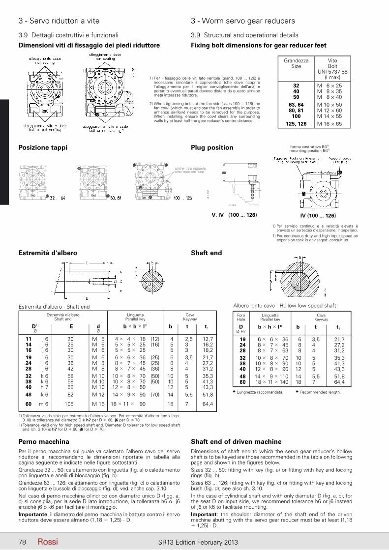
78 SR13 Edition February 2013
3 - Servo riduttori a vite 3 - Worm servo gear reducers
3.9 Dettagli costruttivi e funzionali 3.9 Structural and operational details
Dimensioni viti di fissaggio dei piedi riduttore Fixing bolt dimensions for gear reducer feet
1) Per il fi ssaggio delle viti lato ventola (grand. 100 ... 126) è necessario smontare il copriventola (che deve ricoprire l'alloggiamento per il miglior convogliamento dell'aria) e pertanto eventuali pareti devono distare da questo almeno metà interasse riduttore.
2) When tightening bolts at the fan side (sizes 100 ... 126) the fan cowl (which must enclose the fan assembly in order to enhance air-fl ow) needs to be removed for the purpose. When installing, ensure the cowl clears any surrounding walls by at least half the gear reducer's centre distance.
GrandezzaSize
Vite Bolt
UNI 5737-88(l max)
32 M 16 × 2540 M 18 × 3550 M 18 × 40
63, 64 M 10 × 5080, 81 M 12 × 60
100 M 14 × 55125, 126 M 16 × 65
Posizione tappi Plug position
1) Per servizio continuo e a velocità elevata è previsto un serbatoio d’espansione: interpellarci.
1) For continuous duty and high input speed an expansion tank is envisaged: consult us.
V, IV (100 ... 126) IV (100 ... 126)
Estremità d'albero Shaft end
Albero lento cavo - Hollow low speed shaft
Foro Linguetta Cava Hole Parallel key Keyway
D b � h � l* b t t1 Ø H7
19 6 � 6 � 36 6 3,5 21,7 24 8 � 7 � 45 8 4 27,2 28 8 � 7 � 63 8 4 31,2 32 10 � 8 � 70 10 5 35,3 38 10 � 8 � 90 10 5 41,3 40 12 � 8 � 90 12 5,51) 43,3 48 14 � 9 � 110 14 5,5 51,8 60 18 � 11 � 140 18 7 64,4
* Lunghezza raccomandata. * Recommended length.
Perno macchinaPer il perno macchina sul quale va calettato l’albero cavo del servo riduttore si raccomandano le dimensioni riportate in tabella alla pagina seguente e indicate nelle figure sottostanti.Grandezze 32 ... 50: calettamento con linguetta (fig. a) o calettamento con linguetta e anelli di bloccaggio (fig. b).Grandezze 63 ... 126: calettamento con linguetta (fig. c) o calettamento con linguetta e bussola di bloccaggio (fig. d); ved. anche cap. 3.10.Nel caso di perno macchina cilindrico con diametro unico D (figg. a, c) si consiglia, per la sede D lato introduzione, la tolleranza h6 o j6 anzichè j6 o k6 per facilitare il montaggio.Importante: il diametro del perno macchina in battuta contro il servo riduttore deve essere almeno (1,18 � 1,25) · D.
Shaft end of driven machineDimensions of shaft end to which the servo gear reducer’s hollow shaft is to be keyed are those recommended in the table on following page and shown in the figures below.Sizes 32 ... 50: fitting with key (fig. a) or fitting with key and locking rings (fig. b).Sizes 63 ... 126: fitting with key (fig. c) or fitting with key and locking bush (fig. d); see also ch. 3.10.In the case of cylindrical shaft end with only diameter D (fig. a, c), for the seat D on input side, we recommend tolerance h6 or j6 instead of j6 or k6 to facilitate mounting.Important: the shoulder diameter of the shaft end of the driven ma chine abutting with the servo gear reducer must be at least (1,18 � 1,25) · D.
forma costruttiva B61)
mounting position B61)
Estremità d’albero Linguetta Cava Shaft end Parallel key Keyway
D1) E d b � h � l2) b t t1 Ø Ø
11 j 6 20 M 5 4 � 4 � 18 (12) 4 2,5 12,7 14 j 6 25 M 6 5 � 5 � 25 (16) 5 3 16,2 16 j 6 30 M 6 5 � 5 � 25 5 3 18,2 19 j 6 30 M 6 6 � 6 � 36 (25) 6 3,5 21,7 24 j 6 36 M 8 8 � 7 � 45 (25) 8 4 27,2 28 j 6 42 M 8 8 � 7 � 45 (36) 8 4 31,2 32 k 6 58 M 10 10 � 8 � 70 (50) 10 5 35,3 38 k 6 58 M 10 10 � 8 � 70 (50) 10 5 41,3 40 h 7 58 M 10 12 � 8 � 50 12 5 43,3 48 k 6 82 M 12 14 � 9 � 90 (70) 14 5,5 51,8
60 m 6 105 M 16 18 � 11 � 90 18 7 64,4
1) Tolleranza valida solo per estremità d’albero veloce. Per estremità d’albero lento (cap. 3.10) la tolleranza del diametro D è h7 per D � 60, j6 per D � 70.
1) Tolerance valid only for high speed shaft end. Diameter D tolerance for low speed shaft end (ch. 3.10) is h7 for D � 60, j6 for D � 70.
Estremità d'albero - Shaft end
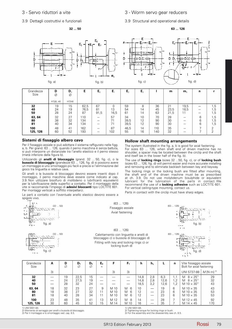
79SR13 Edition February 2013
3 - Servo riduttori a vite 3 - Worm servo gear reducers
32 ... 50 63 ... 126
Grandezza D D3 E E0 E1 E2 E3 l m m0 n r Size Ø Ø H7/j6, k6 H7/h6
32 19 15 62,5 67 0 59 8 36 21 19,5 – 1,5 40 24 19 76,5 81 13 54 14 45 23,5 18,5 – 1,5 50 28 24 87 91,5 16,5 61 14 63 21,5 11,0 – 1,5 63, 64 32 27 110 – 57 34 10 70 28 – 6 1,5 80 38 32 134 – 71 39,5 12 90 30 – 6 1,5 81 40 34 134 – 71 39,5 12 90 30 – 6 1,5 100 48 41 162 – 87 46,5 14 110 35 – 7 2 125, 126 60 52 193 – 102 55 16 140 32 – 7 2
Sistemi di fissaggio albero cavoPer il fissaggio assiale si può adottare il sistema raffigurato nelle figg. a, b. Per grand. 63 ... 126, quando il perno macchina è senza battuta, si può interporre un distanziale tra l’anello elastico e il perno stesso (metà inferiore della figura b).Utilizzando gli anelli di bloccaggio (grand. 32 ... 50, fig. c), o la bussola di bloccaggio (grandezze 63 ... 126, fig. d) si possono avere un montaggio e uno smontaggio più facili e precisi e l’eliminazione del gioco tra linguetta e relativa cava.Gli anelli o la bussola di bloccaggio devono essere inseriti dopo il montaggio, il perno macchina deve essere come indicato al cap. 3.9. Non utilizzare bisolfuro di molibdeno o lubrificanti equivalenti per la lubrificazione delle superfici a contatto. Per il montaggio della vite si raccomanda l’impiego di adesivi bloccanti tipo LOCTITE 601. Per montaggi verticali a soffitto interpellarci.Le parti a contatto con l’eventuale anello elastico devono essere a spigolo vivo.
Hollow shaft mounting arrangementsThe system illustrated in the fig. a, b is good for axial fastening.For sizes 63 ... 126, when shaft end of driven machine has no shoulder, a spacer may be located between the circlip and the shaft end itself (as in the lower half of the fig. b).The use of locking rings (sizes 32 ...50, fig. c), or of locking bush (sizes 63 ... 126, fig. d) will permit easier and more accurate installing and removing and to eliminate backlash between key and keyway.The locking rings or the locking bush are fitted after mounting, the shaft end of the driven machine must be as prescribed at ch. 3.9. Do not use molybdenum bisulphide or equivalent lubricant for the lubrication of the parts in contact. We recommend the use of a locking adhesive such as LOCTITE 601. For vertical ceiling-type mounting, contact us.Parts in contact with the circlip must have sharp edges.
Fissaggio assialeAxial fastening
Calettamento con linguetta e anelli dibloccaggio c) o bussola di bloccaggio d)Fitting with key and locking rings c) or
locking bush d)
GrandezzaSize
A D∅
D1
∅D3
∅E3
≈F F1 h h1 L n Vite fi ssaggio assiale
Bolt for axial fastening
3) 3) 3) UNI 5737-88 M [N m] 2)
32 — 19 22,5 15 — — — 14,8 2,8 6,3 1,1 M 18 × 251) 2940 — 24 27,5 19 — — — 14,8 2,8 12,6 1,2 M 18 × 251) 3250 — 28 32 24 — — — 18,5 3,2 12,6 1,2 M 10 × 301) 43
63, 64 18 32 23 27 09 M 10 M 16 10 — 19 6 M 10 × 35 4380 18 38 27 32 11 M 10 M 16 12 — 23 6 M 10 × 35 5381 18 40 28 34 11 M 10 M 16 12 — 23 6 M 10 × 35 53100 23 48 35 41 13 M 12 M 18 14 — 28 7 M 12 × 45 92
125, 126 30 60 45 52 15 M 14 M 10 16 — 35 7 M 14 × 45 170
(63 ... 126)
(63 ... 126)
1) UNI 5931-84.2) Momento di serraggio per anelli o bussola di bloccaggio.3) Per il montaggio e lo smontaggio ved. cap. 6.5.
1) UNI 5931-84.2) Tightening torque for locking rings or bush.3) For the assembly and the disassembly see ch. 6.5.
3.9 Dettagli costruttivi e funzionali 3.9 Structural and operational details
(63 ... 126)
(63 ... 126)
(32 ... 50)
(32 ... 50)
fi g. a) fi g. b) fi g. c) fi g. d)
fi g. a) fi g. b)
fi g. c) fi g. d)
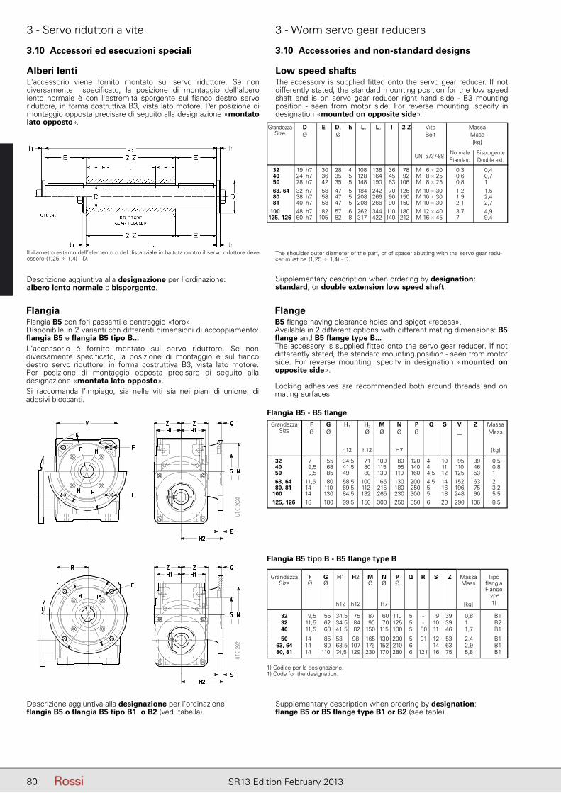
80 SR13 Edition February 2013
3 - Servo riduttori a vite 3 - Worm servo gear reducers
3.10 Accessori ed esecuzioni speciali 3.10 Accessories and non-standard designs
Alberi lentiL'accessorio viene fornito montato sul servo riduttore. Se non diversamente specificato, la posizione di montaggio dell'albero lento normale è con l'estremità sporgente sul fianco destro servo riduttore, in forma costruttiva B3, vista lato motore. Per posizione di montaggio opposta precisare di seguito alla designazione «montato lato opposto».
Low speed shaftsThe accessory is supplied fitted onto the servo gear reducer. If not differently stated, the standard mounting position for the low speed shaft end is on servo gear reducer right hand side - B3 mounting position - seen from motor side. For reverse mounting, specify in designation «mounted on opposite side».
Grandezza D E D1 h L1 L2 l 2 Z Vite Massa Size Ø Ø Bolt Mass Gear [kg] reducer size Normale Bisporgente
UNI 5737-88 Standard Double ext.
32 19 h7 30 28 4 108 138 36 78 M 6 � 20 0,3 0,4 40 24 h7 36 35 5 128 164 45 92 M 8 � 25 0,6 0,7 50 28 h7 42 35 5 148 190 63 106 M 8 � 25 0,8 1 63, 64 32 h7 58 47 5 184 242 70 126 M 10 � 30 1,2 1,5 80 38 h7 58 47 5 208 266 90 150 M 10 � 30 1,9 2,4 81 40 h7 58 47 5 208 266 90 150 M 10 � 30 2,1 2,7 100 48 h7 82 57 6 262 344 110 180 M 12 � 40 3,7 4,9 125, 126 60 h7 105 82 8 317 422 140 212 M 16 � 45 7 9,4
The shoulder outer diameter of the part, or of spacer abutting with the servo gear redu-cer must be (1,25 � 1,4) · D.
Il diametro esterno dell’elemento o del distanziale in battuta contro il servo riduttore deve essere (1,25 � 1,4) · D.
Descrizione aggiuntiva alla designazione per l’ordinazione: albero lento normale o bisporgente.
Supplementary description when ordering by designation: standard, or double extension low speed shaft.
FlangiaFlangia B5 con fori passanti e centraggio «foro»Disponibile in 2 varianti con differenti dimensioni di accoppiamento: flangia B5 e flangia B5 tipo B...L’accessorio è fornito montato sul servo riduttore. Se non diversamente specificato, la posizione di montaggio è sul fianco destro servo riduttore, in forma costruttiva B3, vista lato motore. Per posizione di montaggio opposta precisare di seguito alla designazione «montata lato opposto».Si raccomanda l’impiego, sia nelle viti sia nei piani di unione, di adesivi bloccanti.
FlangeB5 flange having clearance holes and spigot «recess».Available in 2 different options with different mating dimensions: B5 flange and B5 flange type B...The accessory is supplied fitted onto the servo gear reducer. If not differently stated, the standard mounting position - seen from motor side. For reverse mounting, specify in designation «mounted on opposite side».
Locking adhesives are recommended both around threads and on mating surfaces.
Flangia B5 - B5 flange
32 27 55 34,5 71 100 80 120 4 10 95 39 0,5 40 29,5 68 41,5 80 115 95 140 4 11 110 46 0,8 50 29,5 85 49 80 130 110 160 4,5 12 125 53 1 63, 64 11,5 80 58,5 100 165 130 200 4,5 14 152 63 2 80, 81 14 110 69,5 112 215 180 250 5 16 196 75 3,2 100 14 130 84,5 132 265 230 300 5 18 248 90 5,5 125, 126 188 180 99,5 150 300 250 350 6 20 290 106 8,5
Grandezza F G H1 H2 M N P Q S V Z Massa Size Ø Ø Ø Ø Ø Ø Mass h12 h12 H7 [kg]
Descrizione aggiuntiva alla designazione per l’ordinazione: flangia B5 o flangia B5 tipo B1 o B2 (ved. tabella).
Supplementary description when ordering by designation: flange B5 or B5 flange type B1 or B2 (see table).
GrandezzaSize
FØ
GØ
H1 H2 MØ
NØ
PØ
Q R S Z MassaMass
Tipo flangiaFlange type
h12 h12 H7 [kg] 1)
32 9,5 55 34,5 75 87 60 110 5 - 9 39 0,8 B132 11,5 62 34,5 84 90 70 125 5 - 10 39 1 B240 11,5 68 41,5 82 150 115 180 5 80 11 46 1,7 B1
50 14 85 53 98 165 130 200 5 91 12 53 2,4 B163, 64 14 80 63,5 107 176 152 210 6 - 14 63 2,9 B180, 81 14 110 74,5 129 230 170 280 6 121 16 75 5,8 B1
Flangia B5 tipo B - B5 flange type B
1) Codice per la designazione.1) Code for the designation.
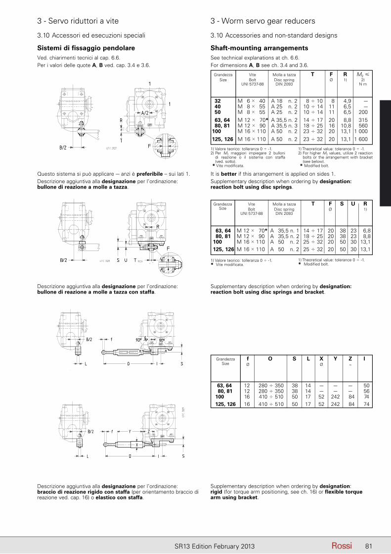
81SR13 Edition February 2013
3 - Servo riduttori a vite 3 - Worm servo gear reducers
Sistemi di fissaggio pendolareVed. chiarimenti tecnici al cap. 6.6.Per i valori delle quote A, B ved. cap. 3.4 e 3.6.
Questo sistema si può applicare – anzi è preferibile – sui lati 1.Descrizione aggiuntiva alla designazione per l’ordinazione: bullone di reazione a molle a tazza.
It is better if this arrangement is applied on sides 1.Supplementary description when ordering by designation: reaction bolt using disc springs.
Descrizione aggiuntiva alla designazione per l’ordinazione: bullone di reazione a molle a tazza con staffa.
Supplementary description when ordering by designation: reaction bolt using disc springs and bracket.
Descrizione aggiuntiva alla designazione per l’ordinazione: braccio di reazione rigido con staffa (per orientamento braccio di reazione ved. cap. 16) o elastico con staffa.
Supplementary description when ordering by designation: rigid (for torque arm positioning, see ch. 16) or flexible torque arm using bracket.
Shaft-mounting arrangementsSee technical explanations at ch. 6.6.For dimensions A, B see ch. 3.4 and 3.6.
Grandezza Vite Molla a tazza T F R M2 � Size Bolt Disc spring Ø 1) 2) UNI 5737-88 DIN 2093 N m
32 M 6 � 40 A 18 n. 2 8 � 10 8 4,9 – 40 M 8 � 55 A 25 n. 2 10 � 14 11 6,5 – 50 M 8 � 55 A 25 n. 2 10 � 14 11 6,5 200 63, 64 M 12 � 70* A 35,5 n. 2 14 � 17 20 8,8 315 80, 81 M 12 � 90 A 35,5 n. 3 18 � 25 16 10,8 560 100 M 16 � 110 A 50 n. 2 23 � 32 20 13,1 1 000 125, 126 M 16 � 110 A 50 n. 2 23 � 32 20 13,1 1 600
1) Valore teorico: tolleranza 0 � -1.2) Per M2 maggiori impiegare 2 bulloni
di reazione o il sistema con staffa (ved. sotto).
* Vite modificata.
1) Theoretical value: tolerance 0 � -1.2) For higher M2 values, utilize 2 reaction
bolts or the arrangement with bracket (see below).
* Modified bolt.
Grandezza Vite Molla a tazza T F S U R Size Bolt Disc spring Ø 1) UNI 5737-88 DIN 2093
63, 64 M 12 � 70* A 35,5 n. 1 14 � 17 20 38 23 6,8 80, 81 M 12 � 90 A 35,5 n. 2 18 � 25 20 38 23 8,8 100 M 16 � 110 A 50 n. 2 25 � 32 20 50 30 13,1 125, 126 M 16 � 110 A 50 n. 2 25 � 32 20 50 30 13,1
1) Valore teorico: tolleranza 0 � -1.* Vite modificata.
1) Theoretical value: tolerance 0 � -1.* Modified bolt.
Grandezza f O S L X Y Z l Size Ø Ø ≈
63, 64 12 280 � 350 38 14 – – – 50 80, 81 12 280 � 350 38 14 – – – 56 100 16 410 � 510 50 17 52 242 84 74 125, 126 16 410 � 510 50 17 52 242 84 74
3.10 Accessori ed esecuzioni speciali 3.10 Accessories and non-standard designs
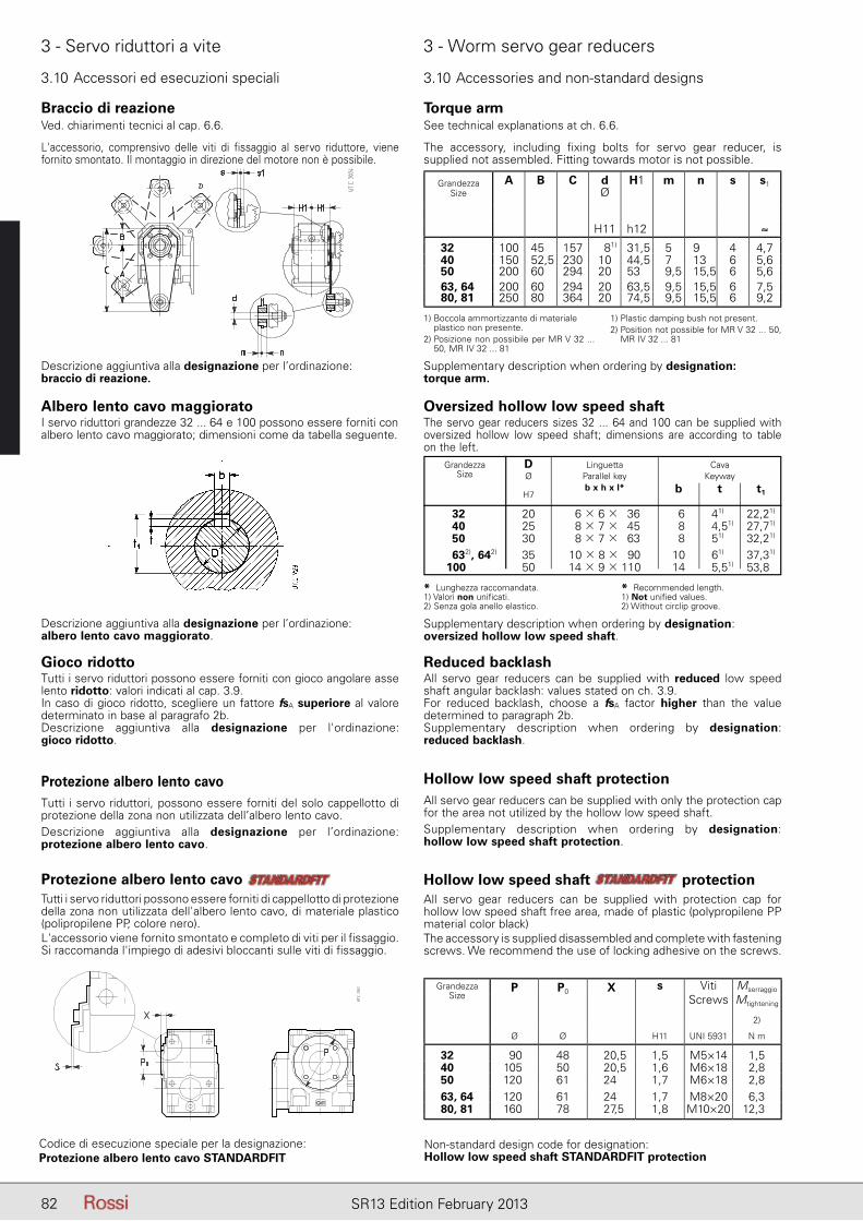
82 SR13 Edition February 2013
3 - Servo riduttori a vite 3 - Worm servo gear reducers
3.10 Accessori ed esecuzioni speciali 3.10 Accessories and non-standard designs
Albero lento cavo maggioratoI servo riduttori grandezze 32 ... 64 e 100 possono essere forniti con albero lento cavo maggiorato; dimensioni come da tabella seguente.
Oversized hollow low speed shaftThe servo gear reducers sizes 32 ... 64 and 100 can be supplied with oversized hollow low speed shaft; dimensions are according to table on the left.
Descrizione aggiuntiva alla designazione per l’ordinazione: albero lento cavo maggiorato.
Supplementary description when ordering by designation: oversized hollow low speed shaft.
Grandezza D Linguetta Cava Size Ø Parallel key Keyway b x h x l* b t t1 H7
32 20 6 � 6 � 36 6 41) 22,21)
40 25 8 � 7 � 45 8 4,51) 27,71)
50 30 8 � 7 � 63 8 51) 32,21)
632), 642) 35 10 � 8 � 90 10 61) 37,31)
100 50 14 � 9 � 110 14 5,51) 53,81)
* Lunghezza raccomandata.1) Valori non unificati.2) Senza gola anello elastico.
* Recommended length.1) Not unified values.2) Without circlip groove.
Gioco ridottoTutti i servo riduttori possono essere forniti con gioco angolare asse lento ridotto: valori indicati al cap. 3.9.In caso di gioco ridotto, scegliere un fattore fsA superiore al valore determinato in base al paragrafo 2b.Descrizione aggiuntiva alla designazione per l'ordinazione: gioco ridotto.
Reduced backlashAll servo gear reducers can be supplied with reduced low speed shaft angular backlash: values stated on ch. 3.9.For reduced backlash, choose a fsA factor higher than the value determined to paragraph 2b.Supplementary description when ordering by designation: reduced backlash.
Protezione albero lento cavoTutti i servo riduttori, possono essere forniti del solo cappellotto di protezione della zona non utilizzata dell’albero lento cavo.Descrizione aggiuntiva alla designazione per l’ordinazione: protezione albero lento cavo.
Hollow low speed shaft protectionAll servo gear reducers can be supplied with only the protection cap for the area not utilized by the hollow low speed shaft.Supplementary description when ordering by designation: hollow low speed shaft protection.
Protezione albero lento cavo Tutti i servo riduttori possono essere forniti di cappellotto di protezione della zona non utilizzata dell'albero lento cavo, di materiale plastico (polipropilene PP, colore nero).L'accessorio viene fornito smontato e completo di viti per il fissaggio. Si raccomanda l'impiego di adesivi bloccanti sulle viti di fissaggio.
Hollow low speed shaft protection All servo gear reducers can be supplied with protection cap for hollow low speed shaft free area, made of plastic (polypropilene PP material color black)The accessory is supplied disassembled and complete with fastening screws. We recommend the use of locking adhesive on the screws.
GrandezzaSize
kk
P P0 X s VitiScrews
Mserraggio
Mtightening
2)
Ø Ø H11 UNI 5931 N m
32 90 48 20,5 1,5 M5×14 1,540 105 50 20,5 1,6 M6×18 2,850 120 61 24 1,7 M6×18 2,863, 64 120 61 24 1,7 M8×20 6,380, 81 160 78 27,5 1,8 M10×20 12,3
Braccio di reazioneVed. chiarimenti tecnici al cap. 6.6.
Torque armSee technical explanations at ch. 6.6.
GrandezzaSize
A B C d H1 m n s s1Ø
H11 h12 ≈
32 100 45 157 81) 31,5 5 9 4 4,740 150 52,5 230 10 44,5 7 13 6 5,650 200 60 294 20 53 9,5 15,5 6 5,663, 64 200 60 294 20 63,5 9,5 15,5 6 7,580, 81 250 80 364 20 74,5 9,5 15,5 6 9,2
1) Boccola ammortizzante di materiale plastico non presente.
2) Posizione non possibile per MR V 32 ... 50, MR IV 32 ... 81
1) Plastic damping bush not present.2) Position not possible for MR V 32 ... 50,
MR IV 32 ... 81
L'accessorio, comprensivo delle viti di fissaggio al servo riduttore, viene fornito smontato. Il montaggio in direzione del motore non è possibile.
The accessory, including fixing bolts for servo gear reducer, is supplied not assembled. Fitting towards motor is not possible.
Descrizione aggiuntiva alla designazione per l’ordinazione: braccio di reazione.
Supplementary description when ordering by designation: torque arm.
Codice di esecuzione speciale per la designazione:Protezione albero lento cavo STANDARDFIT
Non-standard design code for designation:Hollow low speed shaft STANDARDFIT protection
83SR13 Edition February 2013
3 - Servo riduttori a vite 3 - Worm servo gear reducers
3.10 Accessori ed esecuzioni speciali 3.10 Accessories and non-standard designs
Rosetta albero lento cavoTutti i servo riduttori possono essere forniti di rosetta, anello elastico (escluse grand. 32 ... 50), vite per il fissaggio assiale e cappellotto di protezione.Descrizione aggiuntiva alla designazione per l’ordinazione: rosetta albero lento cavo.
Hollow low speed shaft washerAll servo gear reducers can be supplied with washer, circlip (excluding sizes 32 ... 50), bolt for axial fastening and protection cap.Supplementary description when ordering by designation: hollow low speed shaft washer.
Rosetta albero lento cavo con anelli o bussola di bloccaggioTutti i servo riduttori possono essere forniti di rosetta, anello elastico (escluse grand. 32 ... 50), anelli di bloccaggio (grand. 32 ... 50) o bussola di bloccaggio (grand. 63 ... 126), vite per il fissaggio assiale e cappellotto di protezione.Descrizione aggiuntiva alla designazione per l’ordinazione: rosetta albero lento cavo con anelli o bussola di bloccaggio.
Hollow low speed shaft washer with locking rings or bushAll servo gear reducers can be supplied with washer, circlip (exclud-ing sizes 32 ... 50), locking rings (sizes 32 ... 50) or locking bush (sizes 63 ... 126), bolt for axial fastening and protection cap.Supplementary description when ordering by designation: hollow low speed shaft washer with locking rings or bush.
Varie– Albero lento cavo filettato TpN.– Anelli di tenuta speciali; doppia tenuta asse lento (escluso grand.
32 ... 64).– Albero lento cavo con unità di bloccaggio.
Miscellaneous– Hollow low speed with acme-type thread.– Special seal rings; double seal on low speed shaft (excluding sizes
32 ... 64).– Hollow low speed shaft with shrink disc.
Giunto con cava linguetta (servo riduttore tipo R)Descrizione aggiuntiva alla designazione per l’ordinazione: giunto con cava linguetta 1).
1) Previa indicazione da parte del cliente della normativa di riferimento.
Coupling with keyway (servo gear reducer type R)Supplementary description when ordering by designation: coupling with keyway 1).
1) Upon customer's statement of the standards considered.
Sopportazione rinforzata asse lentoI servo riduttori grandezze 63 ... 126 possono essere forniti con cuscinetti a rulli conici sull’asse lento per consentire elevati carichi radiali e/o assiali; valori a richiesta.Descrizione aggiuntiva alla designazione per l’ordinazione: soppor-tazione rinforzata asse lento.
Strengthened low speed shaft bearingsThe servo gear reducers sizes 63 ... 126 can be supplied with taper roller bearings supporting the low speed shaft, allowing increased radial and/or axial loads; other values, consult us.Supplementary description when ordering by designation: strengthened low speed shaft bearings.

84 SR13 Edition February 2013
Pagina lasciata intenzionalmente biancaThis page is intentionally left blank
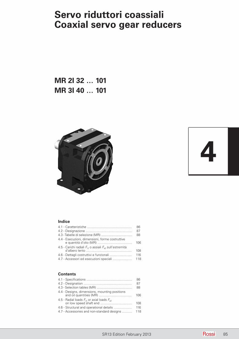
85SR13 Edition February 2013
Servo riduttori coassialiCoaxial servo gear reducers
Indice4.1 - Caratteristiche ................................................. 864.2 - Designazione ................................................... 874.3 - Tabelle di selezione (MR) .................................. 884.4 - Esecuzioni, dimensioni, forme costruttive
e quantità d’olio (MR) ...................................... 1064.5 - Carichi radiali Fr2 o assiali Fa2 sull’estremità
d’albero lento .................................................. 1084.6 - Dettagli costruttivi e funzionali ........................ 1164.7 - Accessori ed esecuzioni speciali ..................... 118
MR 2I 32 … 101MR 3I 40 … 101
Contents4.1 - Specifications .................................................. 864.2 - Designation ..................................................... 874.3 - Selection tables (MR) ....................................... 884.4 - Designs, dimensions, mounting positions
and oil quantities (MR) .................................... 1064.5 - Radial loads Fr2 or axial loads Fa2
on low speed shaft end ................................... 1084.6 - Structural and operational details .................... 1164.7 - Accessories and non-standard designs ........... 118
4
86 SR13 Edition February 2013
4 - Servo riduttori coassiali 4 - Coaxial servo gear reducers
4.1 Caratteristiche
– servo riduttore tipo MR per accoppiamento diretto con il servo motore;
– 6 grandezze (di cui 5 doppie, per un totale di 11 grandezze: 32 … 101);
– 2 classi di gioco angolare asse lento: gioco normale, gioco ridotto (a richiesta);
– calettamento servo motore con pignone prima riduzione montato direttamente sull’estremità d’albero mediante interferenza e linguetta;
– cuscinetti volventi asse lento e assi intermedi: a sfere o a rulli cilindrici;
– pignone ultima riduzione con tre sopporti (escluse grandezze 32 ... 41) per assicurare le migliori condizioni di ingranamento (nessuna ruota a sbalzo, massima rigidezza e sovraccaricabilità, massima silenziosità);
– estremità d’albero lento spostata in avanti (esclusa grand. 40) rispetto al piano flangia, per minore sbalzo a parità di posizione del carico radiale esterno;
– fissaggio universale (brevettato) con piedi inferiori e superiori e flangia B5 integrali alla carcassa (escluse le grand. 32 ... 41 per le quali il fissaggio è o con piedi o con flangia, sempre integrali alla carcassa); massima compattezza e ingombri ridotti (uguali tra 2I e 3I);
– anelli di tenuta per elevata velocità in entrata per tutte le grandezze;– lubrificazione a grasso o a bagno d’olio: a grasso sintetico
per grand. 32 ... 41 o olio sintetico per grand. 50 ... 81 tutte fornite complete di lubrificante per lubrificazione «a vita» e con un tappo (grand. 32 ... 64) o due tappi (grand. 80, 81); a olio sintetico o minerale (ved. cap. 6.7) con tappo di carico con valvola, scarico e livello (grand. 100, 101) tenuta stagna;
– verniciatura: protezione esterna con vernice sintetica nera RAL 9005 (opacità 5 glass) idonea a resistere ai normali ambienti industriali e a consentire ulteriori finiture con vernici sintetiche; protezione interna con vernice a polveri epossidiche idonee a resistere agli oli sintetici.
Rotismo:– a 2, 3 ingranaggi cilindrici;– rapporti di trasmissione nominali secondo R10 (4 ... 160);– ingranaggi di acciaio 16 CrNi4 e 18 NiCrMo5 UNI 7846-78
cementati/ temprati;– ingranaggi cilindrici a dentatura elicoidale con profilo rettificato;– capacità di carico del rotismo calcolata a rottura e pitting.
4.1 Specifications
– servo gear reducer type MR for direct coupling with the servo motor;
– 6 sizes (with 5 size pairs, for a total of 11 sizes: 32 ... 101);– 2 classes of low speed shaft angular backlash: standard backlash,
reduced backlash (on request);– servo motor coupling with first reduction stage pinion directly
fitted with interference and key onto the servo motor shaft end;– bearings on low and intermediate shafts: cylindrical roller or ball
bearings;– pinion of final reduction with three bearings (excluding sizes 32
... 41) in order to ensure best meshing conditions (no overhang wheel, maximum rigidity and overloading capacity, maximum reduction of noise level);
– low speed shaft end shifted forward (excluding size 40) compared to flange plane, for smaller overhang having same position of external radial load;
– universal mounting (patented) having lower and upper feet and B5 flange integral with housing (excluding sizes 32 ... 41 where mounting is either with feet or with flange always integral with housing);
– seal rings for high input speed, available for all sizes;– grease or oil bath lubrication: with synthetic grease for sizes 32
… 41 or synthetic oil for sizes 50 ... 81 all supplied filled with lubricant for lubrication «for life» and one plug (size 32 ... 64) or two plugs (sizes 80, 81); with synthetic or mineral oil (see ch. 6.7) with filler plug with valve, drain and level plug (sizes 100, 101) sealed;
– paint: external coating with black synthetic paint RAL 9005 (opacity 5 glass) suitable to resist the normal industrial environment and to allow further finishing with synthetic paints; internal protection in epoxy powder paint appropriate for resistance to synthetic oils.
Train of gears:– 2, 3 cylindrical gear pairs;– nominal transmission ratios to R10 series (4 ... 160);– casehardened and hardened cylindrical gear pairs in 16 CrNi4 and
18 NiCrMo5 steel according to UNI 7846-78;– helical toothed gear pairs with ground profile;– gear load capacity calculated for tooth breakage and pitting.
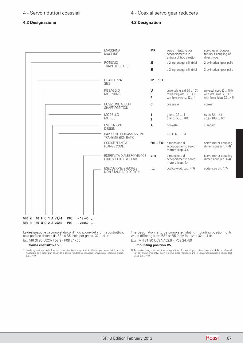
87SR13 Edition February 2013
4 - Servo riduttori coassiali 4 - Coaxial servo gear reducers
MACCHINAMACHINE
MR servo riduttore per accoppiamento in entrata di tipo diretto
servo gear reducer for input coupling of direct type
ROTISMOTRAIN OF GEARS
2I a 2 ingranaggi cilindrici 2 cylindrical gear pairs
3I a 3 ingranaggi cilindrici 3 cylindrical gear pairs
GRANDEZZASIZE
32 ... 101
FISSAGGIOMOUNTING
UPF
universale (grand. 50 ... 101)con piedi (grand. 32 ... 41)con flangia (grand. 32 ... 41)
universal (sizes 50 ... 101)with feet (sizes 32 ... 41)with flange (sizes 32 ... 41)
POSIZIONE ALBERISHAFT POSITION
C coassiale coaxial
MODELLOMODEL
12
grand. 32 ... 41grand. 50 ... 101
sizes 32 ... 41sizes 100 ... 101
ESECUZIONEDESIGN
A normale standard
RAPPORTO DI TRASMISSIONETRANSMISSION RATIO
i = 3,96 ... 154
CODICE FLANCIAFLANGE CODE
P02 ... P10 dimensione di accoppiamento servo motore (cap. 4.4)
servo motor coupling dimensions (ch. 4.4)
ESTREMITÀ D'ALBERO VELOCEHIGH SPEED SHAFT END
d×e dimensione di accoppiamento servo motore (cap. 4.4)
servo motor coupling dimensions (ch. 4.4)
ESECUZIONE SPECIALE NON-STANDARD DESIGN
, ... codice (ved. cap. 4.7) code (see ch. 4.7)
MR 2I 40 F C 1 A /9,41 P05 – 19×40 ,...MR 3I 80 U C 2 A /52,9 P09 – 24×50 ,...
La designazione va completata con l'indicazione della forma costruttiva, solo però se diversa da B31) o B5 (solo per grand. 32 ... 41):Es: MR 3I 80 UC2A / 52,9 - P08 24×50
forma costruttiva V5
1) La designazione della forma costruttiva (ved. cap. 4.4) è riferita, per semplicità, al solo fissaggio con piedi pur essendo i servo riduttori a fissaggio universale (escluse grand. 32 ... 41).
The designation is to be completed stating mounting position, only when differing from B31) or B5 (only for sizes 32 ... 41):E.g.: MR 31 80 UC2A / 52,9 - P08 24×50
mounting position V5
1) To make things easier, the designation of mounting position (see ch. 4.4) is referred to foot mounting only, even if servo gear reducers are in universal mounting (excluded sizes 32 ... 41).
4.2 Designazione 4.2 Designation
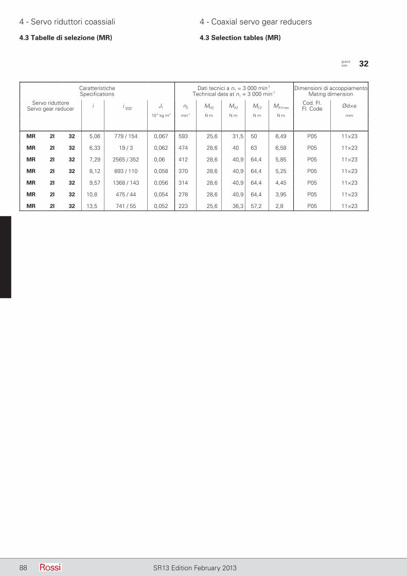
88 SR13 Edition February 2013
4 - Servo riduttori coassiali 4 - Coaxial servo gear reducers
4.3 Tabelle di selezione (MR) 4.3 Selection tables (MR)
CaratteristicheSpecifications
Dati tecnici a n1 = 3 000 min-1
Technical data at n1 = 3 000 min-1Dimensioni di accoppiamento
Mating dimension
Servo riduttoreServo gear reducer i J1 n2 MN2 MA2 ME2 MA1max
Cod. Fl.Fl. Code Ød×e
10-4 kg m2 min-1 N m N m N m N m mm
MR 2I 32 5,06 779 / 154 0,067 593 25,6 31,5 50 6,49 P05 11×23
MR 2I 32 6,33 19 / 3 0,062 474 28,6 40 63 6,58 P05 11×23
MR 2I 32 7,29 2565 / 352 0,06 412 28,6 40,9 64,4 5,85 P05 11×23
MR 2I 32 8,12 893 / 110 0,058 370 28,6 40,9 64,4 5,25 P05 11×23
MR 2I 32 9,57 1368 / 143 0,056 314 28,6 40,9 64,4 4,45 P05 11×23
MR 2I 32 10,8 475 / 44 0,054 278 28,6 40,9 64,4 3,95 P05 11×23
MR 2I 32 13,5 741 / 55 0,052 223 25,6 36,3 57,2 2,8 P05 11×23
grand. size 32
i esattoexact
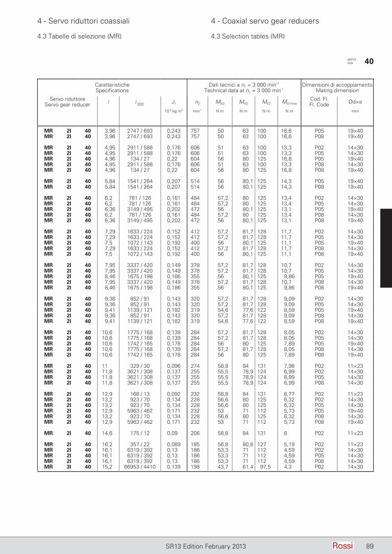
89SR13 Edition February 2013
4 - Servo riduttori coassiali 4 - Coaxial servo gear reducers
4.3 Tabelle di selezione (MR) 4.3 Selection tables (MR)
CaratteristicheSpecifications
Dati tecnici a n1 = 3 000 min-1
Technical data at n1 = 3 000 min-1Dimensioni di accoppiamento
Mating dimension
Servo riduttoreServo gear reducer i J1 n2 MN2 MA2 ME2 MA1max
Cod. Fl.Fl. Code Ød×e
10-4 kg m2 min-1 N m N m N m N m mm
MR 2I 40 3,96 2747 / 693 0,243 757 50 63 100 16,6 P05 19×40MR 2I 40 3,96 2747 / 693 0,243 757 50 63 100 16,6 P08 19×40
MR 2I 40 4,95 2911 / 588 0,176 606 51 63 100 13,3 P02 14×30MR 2I 40 4,95 2911 / 588 0,176 606 51 63 100 13,3 P05 14×30MR 2I 40 4,96 134 / 27 0,22 604 56 80 125 16,8 P05 19×40MR 2I 40 4,95 2911 / 588 0,176 606 51 63 100 13,3 P08 14×30MR 2I 40 4,96 134 / 27 0,22 604 56 80 125 16,8 P08 19×40
MR 2I 40 5,84 1541 / 264 0,207 514 56 80,1 125 14,3 P05 19×40MR 2I 40 5,84 1541 / 264 0,207 514 56 80,1 125 14,3 P08 19×40
MR 2I 40 6,2 781 / 126 0,161 484 57,2 80 125 13,4 P02 14×30MR 2I 40 6,2 781 / 126 0,161 484 57,2 80 125 13,4 P05 14×30MR 2I 40 6,36 3149 / 495 0,202 472 56 80,1 125 13,1 P05 19×40MR 2I 40 6,2 781 / 126 0,161 484 57,2 80 125 13,4 P08 14×30MR 2I 40 6,36 3149 / 495 0,202 472 56 80,1 125 13,1 P08 19×40
MR 2I 40 7,29 1633 / 224 0,152 412 57,2 81,7 128 11,7 P02 14×30MR 2I 40 7,29 1633 / 224 0,152 412 57,2 81,7 128 11,7 P05 14×30MR 2I 40 7,5 1072 / 143 0,192 400 56 80,1 125 11,1 P05 19×40MR 2I 40 7,29 1633 / 224 0,152 412 57,2 81,7 128 11,7 P08 14×30MR 2I 40 7,5 1072 / 143 0,192 400 56 80,1 125 11,1 P08 19×40
MR 2I 40 7,95 3337 / 420 0,149 378 57,2 81,7 128 10,7 P02 14×30MR 2I 40 7,95 3337 / 420 0,149 378 57,2 81,7 128 10,7 P05 14×30MR 2I 40 8,46 1675 / 198 0,186 355 56 80,1 125 9,86 P05 19×40MR 2I 40 7,95 3337 / 420 0,149 378 57,2 81,7 128 10,7 P08 14×30MR 2I 40 8,46 1675 / 198 0,186 355 56 80,1 125 9,86 P08 19×40
MR 2I 40 9,36 852 / 91 0,143 320 57,2 81,7 128 9,09 P02 14×30MR 2I 40 9,36 852 / 91 0,143 320 57,2 81,7 128 9,09 P05 14×30MR 2I 40 9,41 1139 / 121 0,182 319 54,6 77,6 122 8,59 P05 19×40MR 2I 40 9,36 852 / 91 0,143 320 57,2 81,7 128 9,09 P08 14×30MR 2I 40 9,41 1139 / 121 0,182 319 54,6 77,6 122 8,59 P08 19×40
MR 2I 40 10,6 1775 / 168 0,139 284 57,2 81,7 128 8,05 P02 14×30MR 2I 40 10,6 1775 / 168 0,139 284 57,2 81,7 128 8,05 P05 14×30MR 2I 40 10,6 1742 / 165 0,178 284 56 80 125 7,89 P05 19×40MR 2I 40 10,6 1775 / 168 0,139 284 57,2 81,7 128 8,05 P08 14×30MR 2I 40 10,6 1742 / 165 0,178 284 56 80 125 7,89 P08 19×40
MR 2I 40 11 329 / 30 0,096 274 58,8 84 131 7,98 P02 11×23MR 2I 40 11,8 3621 / 308 0,137 255 55,5 78,9 124 6,99 P02 14×30MR 2I 40 11,8 3621 / 308 0,137 255 55,5 78,9 124 6,99 P05 14×30MR 2I 40 11,8 3621 / 308 0,137 255 55,5 78,9 124 6,99 P08 14×30
MR 2I 40 12,9 168 / 13 0,092 232 58,8 84 131 6,77 P02 11×23MR 2I 40 13,2 923 / 70 0,134 228 56,6 80 125 6,32 P02 14×30MR 2I 40 13,2 923 / 70 0,134 228 56,6 80 125 6,32 P05 14×30MR 2I 40 12,9 5963 / 462 0,171 232 53 71 112 5,73 P05 19×40MR 2I 40 13,2 923 / 70 0,134 228 56,6 80 125 6,32 P08 14×30MR 2I 40 12,9 5963 / 462 0,171 232 53 71 112 5,73 P08 19×40
MR 2I 40 14,6 175 / 12 0,09 206 58,8 84 131 6 P02 11×23
MR 2I 40 16,2 357 / 22 0,089 185 56,8 80,8 127 5,19 P02 11×23MR 2I 40 16,1 6319 / 392 0,13 186 53,3 71 112 4,59 P02 14×30MR 2I 40 16,1 6319 / 392 0,13 186 53,3 71 112 4,59 P05 14×30MR 2I 40 16,1 6319 / 392 0,13 186 53,3 71 112 4,59 P08 14×30MR 3I 40 15,2 66953 / 4410 0,139 198 43,7 61,4 97,5 4,3 P02 14×30
grand. size 40
i esattoexact

90 SR13 Edition February 2013
4 - Servo riduttori coassiali 4 - Coaxial servo gear reducers
4.3 Tabelle di selezione (MR) 4.3 Selection tables (MR)
CaratteristicheSpecifications
Dati tecnici a n1 = 3 000 min-1
Technical data at n1 = 3 000 min-1Dimensioni di accoppiamento
Mating dimension
Servo riduttoreServo gear reducer i J1 n2 MN2 MA2 ME2 MA1max
Cod. Fl.Fl. Code Ød×e
10-4 kg m2 min-1 N m N m N m N m mm
MR 2I 40 18,2 91 / 5 0,087 165 57,4 80 125 4,58 P02 11×23
MR 3I 40 19 17963 / 945 0,137 158 54,7 76,9 122 4,3 P02 14×30
MR 2I 40 22,3 89 / 4 0,085 135 53,6 71 112 3,32 P02 11×23MR 3I 40 22,4 37559 / 1680 0,137 134 63,0 85 132 4,04 P02 14×30
MR 3I 40 24,4 76751 / 3150 0,136 123 63,0 90,0 140 3,93 P02 14×30
MR 3I 40 26,2 3542 / 135 0,089 114 56,2 79,0 125 3,2 P02 11×23MR 3I 40 28,7 13064 / 455 0,136 104 63,0 90,0 140 3,33 P02 14×30
MR 3I 40 30,9 3703 / 120 0,089 97,2 64,8 85 132 2,93 P02 11×23MR 3I 40 32,4 8165 / 252 0,135 92,6 63,0 90,0 140 2,95 P02 14×30
MR 3I 40 33,6 7567 / 225 0,089 89,2 64,8 90 140 2,85 P02 11×23MR 3I 40 37,2 83283 / 2240 0,124 80,7 54,5 76 122 2,17 P02 14×30
MR 3I 40 39,6 2576 / 65 0,088 75,7 64,8 90 140 2,42 P02 11×23MR 3I 40 40,5 56729 / 1400 0,124 74 59,4 82,9 133 2,17 P02 14×30
MR 3I 40 44,7 805 / 18 0,088 67 64,8 90 140 2,14 P02 11×23MR 3I 40 47,7 21726 / 455 0,123 62,8 65,8 90 140 2 P02 14×30
MR 3I 40 51,3 8211 / 160 0,082 58,5 56,0 78 125 1,62 P02 11×23MR 3I 40 53,9 6035 / 112 0,123 55,7 65,8 90 140 1,78 P02 14×30
MR 3I 40 55,9 5593 / 100 0,082 53,6 61,0 85 136 1,62 P02 11×23
MR 3I 40 65,9 4284 / 65 0,082 45,5 67,7 90 140 1,45 P02 11×23
MR 3I 40 74,4 595 / 8 0,082 40,3 67,7 90 140 1,29 P02 11×23
MR 3I 40 92,8 4641 / 50 0,082 32,3 61,5 80 125 0,917 P02 11×23
grand. size 40
i esattoexact

91SR13 Edition February 2013
4 - Servo riduttori coassiali 4 - Coaxial servo gear reducers
4.3 Tabelle di selezione (MR) 4.3 Selection tables (MR)
CaratteristicheSpecifications
Dati tecnici a n1 = 3 000 min-1
Technical data at n1 = 3 000 min-1Dimensioni di accoppiamento
Mating dimension
Servo riduttoreServo gear reducer i J1 n2 MN2 MA2 ME2 MA1max
Cod. Fl.Fl. Code Ød×e
10-4 kg m2 min-1 N m N m N m N m mm
MR 2I 41 4,96 134 / 27 0,23 604 63 90 140 18,9 P05 19×40MR 2I 41 4,96 134 / 27 0,23 604 63 90 140 18,9 P08 19×40
MR 2I 41 5,84 1541 / 264 0,215 514 71 100 160 17,9 P05 19×40MR 2I 41 5,84 1541 / 264 0,215 514 71 100 160 17,9 P08 19×40
MR 2I 41 6,36 3149 / 495 0,209 472 71 95,1 150 15,6 P05 19×40MR 2I 41 6,36 3149 / 495 0,209 472 71 95,1 150 15,6 P08 19×40
MR 2I 41 7,29 1633 / 224 0,158 412 72,5 102 163 14,6 P02 14×30MR 2I 41 7,29 1633 / 224 0,158 412 72,5 102 163 14,6 P05 14×30MR 2I 41 7,5 1072 / 143 0,199 400 71 100 160 13,9 P05 19×40MR 2I 41 7,29 1633 / 224 0,158 412 72,5 102 163 14,6 P08 14×30MR 2I 41 7,5 1072 / 143 0,199 400 71 100 160 13,9 P08 19×40
MR 2I 41 7,95 3337 / 420 0,154 378 72,5 97 153 12,7 P02 14×30MR 2I 41 7,95 3337 / 420 0,154 378 72,5 97 153 12,7 P05 14×30MR 2I 41 8,46 1675 / 198 0,193 355 71 100 160 12,3 P05 19×40MR 2I 41 7,95 3337 / 420 0,154 378 72,5 97 153 12,7 P08 14×30MR 2I 41 8,46 1675 / 198 0,193 355 71 100 160 12,3 P08 19×40
MR 2I 41 9,36 852 / 91 0,147 320 72,5 102 163 11,4 P02 14×30MR 2I 41 9,36 852 / 91 0,147 320 72,5 102 163 11,4 P05 14×30MR 2I 41 9,41 1139 / 121 0,188 319 69 97,6 155 10,8 P05 19×40MR 2I 41 9,36 852 / 91 0,147 320 72,5 102 163 11,4 P08 14×30MR 2I 41 9,41 1139 / 121 0,188 319 69 97,6 155 10,8 P08 19×40
MR 2I 41 10,6 1775 / 168 0,143 284 72,1 102 163 10 P02 14×30MR 2I 41 10,6 1775 / 168 0,143 284 72,1 102 163 10 P05 14×30MR 2I 41 10,6 1742 / 165 0,183 284 67 95 150 9,37 P05 19×40MR 2I 41 10,6 1775 / 168 0,143 284 72,1 102 163 10 P08 14×30MR 2I 41 10,6 1742 / 165 0,183 284 67 95 150 9,37 P08 19×40
MR 2I 41 11,8 3621 / 308 0,14 255 69,9 98,8 157 8,75 P02 14×30MR 2I 41 11,8 3621 / 308 0,14 255 69,9 98,8 157 8,75 P05 14×30MR 2I 41 11,8 3621 / 308 0,14 255 69,9 98,8 157 8,75 P08 14×30
MR 2I 41 13,2 923 / 70 0,137 228 67,7 95 150 7,5 P02 14×30MR 2I 41 13,2 923 / 70 0,137 228 67,7 95 150 7,5 P05 14×30MR 2I 41 13,2 923 / 70 0,137 228 67,7 95 150 7,5 P08 14×30
MR 3I 41 19 17963 / 945 0,138 158 61 86,8 137 4,85 P02 14×30
MR 3I 41 22,4 37559 / 1680 0,137 134 71,9 102 161 4,85 P02 14×30
MR 3I 41 24,4 76751 / 3150 0,137 123 75,4 106 169 4,63 P02 14×30
MR 3I 41 26,2 3542 / 135 0,09 114 62,8 89,1 141 3,61 P02 11×23MR 3I 41 28,7 13064 / 455 0,136 104 79,8 112 180 4,15 P02 14×30
MR 3I 41 30,9 3703 / 120 0,089 97,2 73,8 105 165 3,61 P02 11×23MR 3I 41 32,4 8165 / 252 0,136 92,6 77,6 106 170 3,48 P02 14×30
MR 3I 41 33,6 7567 / 225 0,089 89,2 77,5 106 170 3,35 P02 11×23MR 3I 41 37,2 83283 / 2240 0,124 80,7 60,9 86,2 136 2,46 P02 14×30
MR 3I 41 39,6 2576 / 65 0,089 75,7 82 112 180 3 P02 11×23MR 3I 41 40,5 56729 / 1400 0,124 74 66,4 93,9 149 2,46 P02 14×30
MR 3I 41 44,7 805 / 18 0,088 67 79,3 106 170 2,52 P02 11×23MR 3I 41 47,7 21726 / 455 0,124 62,8 78,2 111 175 2,46 P02 14×30
MR 3I 41 51,3 8211 / 160 0,082 58,5 62,5 88,5 140 1,83 P02 11×23MR 3I 41 53,9 6035 / 112 0,123 55,7 80,2 106 170 2,09 P02 14×30
MR 3I 41 55,9 5593 / 100 0,082 53,6 68,1 96,4 153 1,83 P02 11×23
MR 3I 41 65,9 4284 / 65 0,082 45,5 80,3 112 180 1,8 P02 11×23
MR 3I 41 74,4 595 / 8 0,082 40,3 82 106 170 1,52 P02 11×23
grand. size 41
i esattoexact
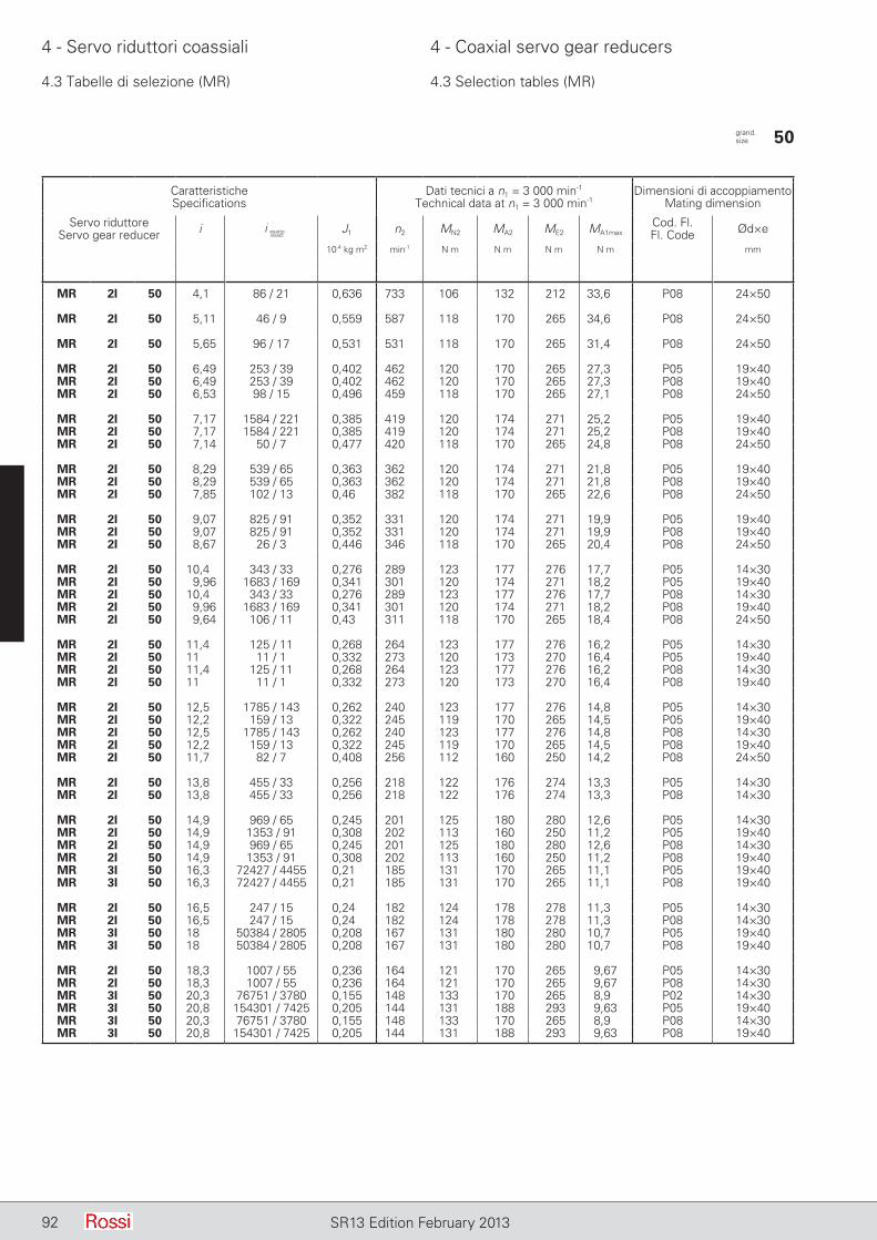
92 SR13 Edition February 2013
4 - Servo riduttori coassiali 4 - Coaxial servo gear reducers
CaratteristicheSpecifications
Dati tecnici a n1 = 3 000 min-1
Technical data at n1 = 3 000 min-1Dimensioni di accoppiamento
Mating dimension
Servo riduttoreServo gear reducer i J1 n2 MN2 MA2 ME2 MA1max
Cod. Fl.Fl. Code Ød×e
10-4 kg m2 min-1 N m N m N m N m mm
MR 2I 50 4,1 86 / 21 0,636 733 106 132 212 33,6 P08 24×50
MR 2I 50 5,11 46 / 9 0,559 587 118 170 265 34,6 P08 24×50
MR 2I 50 5,65 96 / 17 0,531 531 118 170 265 31,4 P08 24×50
MR 2I 50 6,49 253 / 39 0,402 462 120 170 265 27,3 P05 19×40MR 2I 50 6,49 253 / 39 0,402 462 120 170 265 27,3 P08 19×40MR 2I 50 6,53 98 / 15 0,496 459 118 170 265 27,1 P08 24×50
MR 2I 50 7,17 1584 / 221 0,385 419 120 174 271 25,2 P05 19×40MR 2I 50 7,17 1584 / 221 0,385 419 120 174 271 25,2 P08 19×40MR 2I 50 7,14 50 / 7 0,477 420 118 170 265 24,8 P08 24×50
MR 2I 50 8,29 539 / 65 0,363 362 120 174 271 21,8 P05 19×40MR 2I 50 8,29 539 / 65 0,363 362 120 174 271 21,8 P08 19×40MR 2I 50 7,85 102 / 13 0,46 382 118 170 265 22,6 P08 24×50
MR 2I 50 9,07 825 / 91 0,352 331 120 174 271 19,9 P05 19×40MR 2I 50 9,07 825 / 91 0,352 331 120 174 271 19,9 P08 19×40MR 2I 50 8,67 26 / 3 0,446 346 118 170 265 20,4 P08 24×50
MR 2I 50 10,4 343 / 33 0,276 289 123 177 276 17,7 P05 14×30MR 2I 50 9,96 1683 / 169 0,341 301 120 174 271 18,2 P05 19×40MR 2I 50 10,4 343 / 33 0,276 289 123 177 276 17,7 P08 14×30MR 2I 50 9,96 1683 / 169 0,341 301 120 174 271 18,2 P08 19×40MR 2I 50 9,64 106 / 11 0,43 311 118 170 265 18,4 P08 24×50
MR 2I 50 11,4 125 / 11 0,268 264 123 177 276 16,2 P05 14×30MR 2I 50 11 11 / 1 0,332 273 120 173 270 16,4 P05 19×40MR 2I 50 11,4 125 / 11 0,268 264 123 177 276 16,2 P08 14×30MR 2I 50 11 11 / 1 0,332 273 120 173 270 16,4 P08 19×40
MR 2I 50 12,5 1785 / 143 0,262 240 123 177 276 14,8 P05 14×30MR 2I 50 12,2 159 / 13 0,322 245 119 170 265 14,5 P05 19×40MR 2I 50 12,5 1785 / 143 0,262 240 123 177 276 14,8 P08 14×30MR 2I 50 12,2 159 / 13 0,322 245 119 170 265 14,5 P08 19×40MR 2I 50 11,7 82 / 7 0,408 256 112 160 250 14,2 P08 24×50
MR 2I 50 13,8 455 / 33 0,256 218 122 176 274 13,3 P05 14×30MR 2I 50 13,8 455 / 33 0,256 218 122 176 274 13,3 P08 14×30
MR 2I 50 14,9 969 / 65 0,245 201 125 180 280 12,6 P05 14×30MR 2I 50 14,9 1353 / 91 0,308 202 113 160 250 11,2 P05 19×40MR 2I 50 14,9 969 / 65 0,245 201 125 180 280 12,6 P08 14×30MR 2I 50 14,9 1353 / 91 0,308 202 113 160 250 11,2 P08 19×40MR 3I 50 16,3 72427 / 4455 0,21 185 131 170 265 11,1 P05 19×40MR 3I 50 16,3 72427 / 4455 0,21 185 131 170 265 11,1 P08 19×40
MR 2I 50 16,5 247 / 15 0,24 182 124 178 278 11,3 P05 14×30MR 2I 50 16,5 247 / 15 0,24 182 124 178 278 11,3 P08 14×30MR 3I 50 18 50384 / 2805 0,208 167 131 180 280 10,7 P05 19×40MR 3I 50 18 50384 / 2805 0,208 167 131 180 280 10,7 P08 19×40
MR 2I 50 18,3 1007 / 55 0,236 164 121 170 265 9,67 P05 14×30MR 2I 50 18,3 1007 / 55 0,236 164 121 170 265 9,67 P08 14×30MR 3I 50 20,3 76751 / 3780 0,155 148 133 170 265 8,9 P02 14×30MR 3I 50 20,8 154301 / 7425 0,205 144 131 188 293 9,63 P05 19×40MR 3I 50 20,3 76751 / 3780 0,155 148 133 170 265 8,9 P08 14×30MR 3I 50 20,8 154301 / 7425 0,205 144 131 188 293 9,63 P08 19×40
4.3 Tabelle di selezione (MR) 4.3 Selection tables (MR)
grand. size 50
i esattoexact
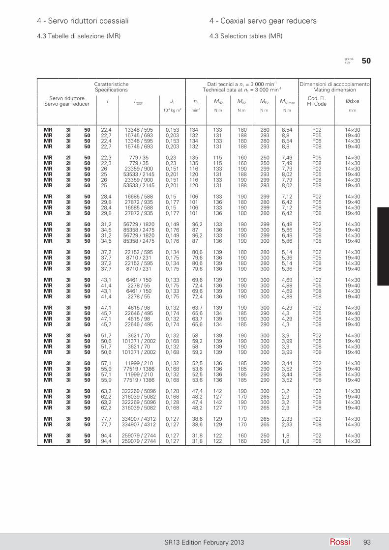
93SR13 Edition February 2013
4 - Servo riduttori coassiali 4 - Coaxial servo gear reducers
4.3 Tabelle di selezione (MR) 4.3 Selection tables (MR)
CaratteristicheSpecifications
Dati tecnici a n1 = 3 000 min-1
Technical data at n1 = 3 000 min-1Dimensioni di accoppiamento
Mating dimension
Servo riduttoreServo gear reducer i J1 n2 MN2 MA2 ME2 MA1max
Cod. Fl.Fl. Code Ød×e
10-4 kg m2 min-1 N m N m N m N m mm
MR 3I 50 22,4 13348 / 595 0,153 134 133 180 280 8,54 P02 14×30MR 3I 50 22,7 15745 / 693 0,203 132 131 188 293 8,8 P05 19×40MR 3I 50 22,4 13348 / 595 0,153 134 133 180 280 8,54 P08 14×30MR 3I 50 22,7 15745 / 693 0,203 132 131 188 293 8,8 P08 19×40
MR 2I 50 22,3 779 / 35 0,23 135 115 160 250 7,49 P05 14×30MR 2I 50 22,3 779 / 35 0,23 135 115 160 250 7,49 P08 14×30MR 3I 50 26 23359 / 900 0,151 116 133 190 299 7,79 P02 14×30MR 3I 50 25 53533 / 2145 0,201 120 131 188 293 8,02 P05 19×40MR 3I 50 26 23359 / 900 0,151 116 133 190 299 7,79 P08 14×30MR 3I 50 25 53533 / 2145 0,201 120 131 188 293 8,02 P08 19×40
MR 3I 50 28,4 16685 / 588 0,15 106 133 190 299 7,12 P02 14×30MR 3I 50 29,8 27872 / 935 0,177 101 136 180 280 6,42 P05 19×40MR 3I 50 28,4 16685 / 588 0,15 106 133 190 299 7,12 P08 14×30MR 3I 50 29,8 27872 / 935 0,177 101 136 180 280 6,42 P08 19×40
MR 3I 50 31,2 56729 / 1820 0,149 96,2 133 190 299 6,48 P02 14×30MR 3I 50 34,5 85358 / 2475 0,176 87 136 190 300 5,86 P05 19×40MR 3I 50 31,2 56729 / 1820 0,149 96,2 133 190 299 6,48 P08 14×30MR 3I 50 34,5 85358 / 2475 0,176 87 136 190 300 5,86 P08 19×40
MR 3I 50 37,2 22152 / 595 0,134 80,6 139 180 280 5,14 P02 14×30MR 3I 50 37,7 8710 / 231 0,175 79,6 136 190 300 5,36 P05 19×40MR 3I 50 37,2 22152 / 595 0,134 80,6 139 180 280 5,14 P08 14×30MR 3I 50 37,7 8710 / 231 0,175 79,6 136 190 300 5,36 P08 19×40
MR 3I 50 43,1 6461 / 150 0,133 69,6 139 190 300 4,69 P02 14×30MR 3I 50 41,4 2278 / 55 0,175 72,4 136 190 300 4,88 P05 19×40MR 3I 50 43,1 6461 / 150 0,133 69,6 139 190 300 4,69 P08 14×30MR 3I 50 41,4 2278 / 55 0,175 72,4 136 190 300 4,88 P08 19×40
MR 3I 50 47,1 4615 / 98 0,132 63,7 139 190 300 4,29 P02 14×30MR 3I 50 45,7 22646 / 495 0,174 65,6 134 185 290 4,3 P05 19×40MR 3I 50 47,1 4615 / 98 0,132 63,7 139 190 300 4,29 P08 14×30MR 3I 50 45,7 22646 / 495 0,174 65,6 134 185 290 4,3 P08 19×40
MR 3I 50 51,7 3621 / 70 0,132 58 139 190 300 3,9 P02 14×30MR 3I 50 50,6 101371 / 2002 0,168 59,2 139 190 300 3,99 P05 19×40MR 3I 50 51,7 3621 / 70 0,132 58 139 190 300 3,9 P08 14×30MR 3I 50 50,6 101371 / 2002 0,168 59,2 139 190 300 3,99 P08 19×40
MR 3I 50 57,1 11999 / 210 0,132 52,5 136 185 290 3,44 P02 14×30MR 3I 50 55,9 77519 / 1386 0,168 53,6 136 185 290 3,52 P05 19×40MR 3I 50 57,1 11999 / 210 0,132 52,5 136 185 290 3,44 P08 14×30MR 3I 50 55,9 77519 / 1386 0,168 53,6 136 185 290 3,52 P08 19×40
MR 3I 50 63,2 322269 / 5096 0,128 47,4 142 190 300 3,2 P02 14×30MR 3I 50 62,2 316039 / 5082 0,168 48,2 127 170 265 2,9 P05 19×40MR 3I 50 63,2 322269 / 5096 0,128 47,4 142 190 300 3,2 P08 14×30MR 3I 50 62,2 316039 / 5082 0,168 48,2 127 170 265 2,9 P08 19×40
MR 3I 50 77,7 334907 / 4312 0,127 38,6 129 170 265 2,33 P02 14×30MR 3I 50 77,7 334907 / 4312 0,127 38,6 129 170 265 2,33 P08 14×30
MR 3I 50 94,4 259079 / 2744 0,127 31,8 122 160 250 1,8 P02 14×30MR 3I 50 94,4 259079 / 2744 0,127 31,8 122 160 250 1,8 P08 14×30
grand. size 50
i esattoexact
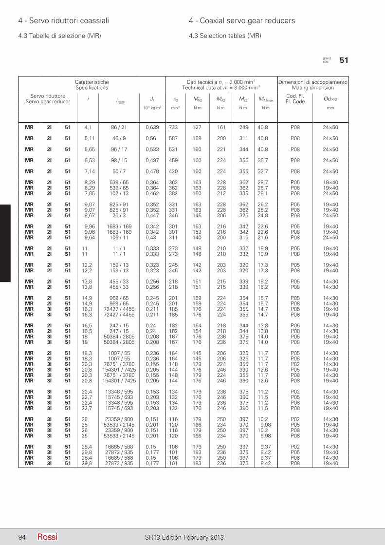
94 SR13 Edition February 2013
4 - Servo riduttori coassiali 4 - Coaxial servo gear reducers
4.3 Tabelle di selezione (MR) 4.3 Selection tables (MR)
CaratteristicheSpecifications
Dati tecnici a n1 = 3 000 min-1
Technical data at n1 = 3 000 min-1Dimensioni di accoppiamento
Mating dimension
Servo riduttoreServo gear reducer i J1 n2 MN2 MA2 ME2 MA1max
Cod. Fl.Fl. Code Ød×e
10-4 kg m2 min-1 N m N m N m N m mm
MR 2I 51 4,1 86 / 21 0,639 733 127 161 249 40,8 P08 24×50
MR 2I 51 5,11 46 / 9 0,56 587 158 200 311 40,8 P08 24×50
MR 2I 51 5,65 96 / 17 0,533 531 160 221 344 40,8 P08 24×50
MR 2I 51 6,53 98 / 15 0,497 459 160 224 355 35,7 P08 24×50
MR 2I 51 7,14 50 / 7 0,478 420 160 224 355 32,7 P08 24×50
MR 2I 51 8,29 539 / 65 0,364 362 163 228 362 28,7 P05 19×40MR 2I 51 8,29 539 / 65 0,364 362 163 228 362 28,7 P08 19×40MR 2I 51 7,85 102 / 13 0,462 382 150 212 335 28,1 P08 24×50
MR 2I 51 9,07 825 / 91 0,352 331 163 228 362 26,2 P05 19×40MR 2I 51 9,07 825 / 91 0,352 331 163 228 362 26,2 P08 19×40MR 2I 51 8,67 26 / 3 0,447 346 145 206 325 24,8 P08 24×50
MR 2I 51 9,96 1683 / 169 0,342 301 153 216 342 22,6 P05 19×40MR 2I 51 9,96 1683 / 169 0,342 301 153 216 342 22,6 P08 19×40MR 2I 51 9,64 106 / 11 0,43 311 140 200 315 21,6 P08 24×50
MR 2I 51 11 11 / 1 0,333 273 148 210 332 19,9 P05 19×40MR 2I 51 11 11 / 1 0,333 273 148 210 332 19,9 P08 19×40
MR 2I 51 12,2 159 / 13 0,323 245 142 203 320 17,3 P05 19×40MR 2I 51 12,2 159 / 13 0,323 245 142 203 320 17,3 P08 19×40
MR 2I 51 13,8 455 / 33 0,256 218 151 215 339 16,2 P05 14×30MR 2I 51 13,8 455 / 33 0,256 218 151 215 339 16,2 P08 14×30
MR 2I 51 14,9 969 / 65 0,245 201 159 224 354 15,7 P05 14×30MR 2I 51 14,9 969 / 65 0,245 201 159 224 354 15,7 P08 14×30MR 3I 51 16,3 72427 / 4455 0,211 185 176 224 355 14,7 P05 19×40MR 3I 51 16,3 72427 / 4455 0,211 185 176 224 355 14,7 P08 19×40
MR 2I 51 16,5 247 / 15 0,24 182 154 218 344 13,8 P05 14×30MR 2I 51 16,5 247 / 15 0,24 182 154 218 344 13,8 P08 14×30MR 3I 51 18 50384 / 2805 0,208 167 176 236 375 14,0 P05 19×40MR 3I 51 18 50384 / 2805 0,208 167 176 236 375 14,0 P08 19×40
MR 2I 51 18,3 1007 / 55 0,236 164 145 206 325 11,7 P05 14×30MR 2I 51 18,3 1007 / 55 0,236 164 145 206 325 11,7 P08 14×30MR 3I 51 20,3 76751 / 3780 0,155 148 179 224 355 11,7 P02 14×30MR 3I 51 20,8 154301 / 7425 0,205 144 176 246 390 12,6 P05 19×40MR 3I 51 20,3 76751 / 3780 0,155 148 179 224 355 11,7 P08 14×30MR 3I 51 20,8 154301 / 7425 0,205 144 176 246 390 12,6 P08 19×40
MR 3I 51 22,4 13348 / 595 0,153 134 179 236 375 11,2 P02 14×30MR 3I 51 22,7 15745 / 693 0,203 132 176 246 390 11,5 P05 19×40MR 3I 51 22,4 13348 / 595 0,153 134 179 236 375 11,2 P08 14×30MR 3I 51 22,7 15745 / 693 0,203 132 176 246 390 11,5 P08 19×40
MR 3I 51 26 23359 / 900 0,151 116 179 250 397 10,2 P02 14×30MR 3I 51 25 53533 / 2145 0,201 120 166 234 370 9,98 P05 19×40MR 3I 51 26 23359 / 900 0,151 116 179 250 397 10,2 P08 14×30MR 3I 51 25 53533 / 2145 0,201 120 166 234 370 9,98 P08 19×40
MR 3I 51 28,4 16685 / 588 0,15 106 179 250 397 9,37 P02 14×30MR 3I 51 29,8 27872 / 935 0,177 101 183 236 375 8,42 P05 19×40MR 3I 51 28,4 16685 / 588 0,15 106 179 250 397 9,37 P08 14×30MR 3I 51 29,8 27872 / 935 0,177 101 183 236 375 8,42 P08 19×40
grand. size 51
i esattoexact

95SR13 Edition February 2013
4 - Servo riduttori coassiali 4 - Coaxial servo gear reducers
4.3 Tabelle di selezione (MR) 4.3 Selection tables (MR)
CaratteristicheSpecifications
Dati tecnici a n1 = 3 000 min-1
Technical data at n1 = 3 000 min-1Dimensioni di accoppiamento
Mating dimension
Servo riduttoreServo gear reducer i J1 n2 MN2 MA2 ME2 MA1max
Cod. Fl.Fl. Code Ød×e
10-4 kg m2 min-1 N m N m N m N m mm
MR 3I 51 31,2 56729 / 1820 0,149 96,2 169 236 375 8,05 P02 14×30MR 3I 51 34,5 85358 / 2475 0,176 87 183 250 400 7,71 P05 19×40MR 3I 51 31,2 56729 / 1820 0,149 96,2 169 236 375 8,05 P08 14×30MR 3I 51 34,5 85358 / 2475 0,176 87 183 250 400 7,71 P08 19×40
MR 3I 51 37,2 22152 / 595 0,134 80,6 187 236 375 6,74 P02 14×30MR 3I 51 37,7 8710 / 231 0,176 79,6 183 250 400 7,05 P05 19×40MR 3I 51 37,2 22152 / 595 0,134 80,6 187 236 375 6,74 P08 14×30MR 3I 51 37,7 8710 / 231 0,176 79,6 183 250 400 7,05 P08 19×40
MR 3I 51 43,1 6461 / 150 0,133 69,6 187 250 400 6,17 P02 14×30MR 3I 51 41,4 2278 / 55 0,175 72,4 173 236 375 6,06 P05 19×40MR 3I 51 43,1 6461 / 150 0,133 69,6 187 250 400 6,17 P08 14×30MR 3I 51 41,4 2278 / 55 0,175 72,4 173 236 375 6,06 P08 19×40
MR 3I 51 47,1 4615 / 98 0,132 63,7 187 250 400 5,65 P02 14×30MR 3I 51 45,7 22646 / 495 0,174 65,6 168 230 365 5,35 P05 19×40MR 3I 51 47,1 4615 / 98 0,132 63,7 187 250 400 5,65 P08 14×30MR 3I 51 45,7 22646 / 495 0,174 65,6 168 230 365 5,35 P08 19×40
MR 3I 51 51,7 3621 / 70 0,132 58 176 236 375 4,85 P02 14×30MR 3I 51 50,6 101371 / 2002 0,168 59,2 176 236 375 4,96 P05 19×40MR 3I 51 51,7 3621 / 70 0,132 58 176 236 375 4,85 P08 14×30MR 3I 51 50,6 101371 / 2002 0,168 59,2 176 236 375 4,96 P08 19×40
MR 3I 51 57,1 11999 / 210 0,132 52,5 171 230 365 4,28 P02 14×30MR 3I 51 55,9 77519 / 1386 0,168 53,6 171 230 365 4,37 P05 19×40MR 3I 51 57,1 11999 / 210 0,132 52,5 171 230 365 4,28 P08 14×30MR 3I 51 55,9 77519 / 1386 0,168 53,6 171 230 365 4,37 P08 19×40
MR 3I 51 63,2 322269 / 5096 0,128 47,4 180 236 375 3,97 P02 14×30MR 3I 51 62,2 316039 / 5082 0,168 48,2 157 206 325 3,52 P05 19×40MR 3I 51 63,2 322269 / 5096 0,128 47,4 180 236 375 3,97 P08 14×30MR 3I 51 62,2 316039 / 5082 0,168 48,2 157 206 325 3,52 P08 19×40
MR 3I 51 77,7 334907 / 4312 0,127 38,6 159 206 325 2,82 P02 14×30MR 3I 51 77,7 334907 / 4312 0,127 38,6 159 206 325 2,82 P08 14×30
grand. size 51
i esattoexact

96 SR13 Edition February 2013
4 - Servo riduttori coassiali 4 - Coaxial servo gear reducers
4.3 Tabelle di selezione (MR) 4.3 Selection tables (MR)
CaratteristicheSpecifications
Dati tecnici a n1 = 3 000 min-1
Technical data at n1 = 3 000 min-1Dimensioni di accoppiamento
Mating dimension
Servo riduttoreServo gear reducer i J1 n2 MN2 MA2 ME2 MA1max
Cod. Fl.Fl. Code Ød×e
10-4 kg m2 min-1 N m N m N m N m mm
MR 2I 63 4 4 / 1 2,07 750 212 265 425 69 P09 28×60
MR 2I 63 5,06 86 / 17 1,84 593 236 335 530 69 P09 28×60
MR 2I 63 5,63 45 / 8 1,76 533 236 335 530 62 P09 28×60
MR 2I 63 6,42 1419 / 221 1,3 467 241 335 530 54,3 P08 24×50MR 2I 63 6,42 1419 / 221 1,3 467 241 335 530 54,3 P09 24×50MR 2I 63 6,57 46 / 7 1,65 457 236 335 530 53,1 P09 28×60
MR 2I 63 7,14 1485 / 208 1,25 420 241 342 541 49,9 P08 24×50MR 2I 63 7,14 1485 / 208 1,25 420 241 342 541 49,9 P09 24×50MR 2I 63 7,23 94 / 13 1,59 415 236 335 530 48,3 P09 28×60
MR 2I 63 8,34 759 / 91 1,18 360 241 342 541 42,7 P08 24×50MR 2I 63 8,34 759 / 91 1,18 360 241 342 541 42,7 P09 24×50MR 2I 63 8 8 / 1 1,54 375 236 335 530 43,6 P09 28×60
MR 2I 63 9,18 1551 / 169 1,15 327 241 342 541 38,8 P08 24×50MR 2I 63 9,18 1551 / 169 1,15 327 241 342 541 38,8 P09 24×50MR 2I 63 8,91 98 / 11 1,5 337 236 335 530 39,2 P09 28×60
MR 2I 63 10,2 132 / 13 1,12 295 241 342 541 35 P08 24×50MR 2I 63 10,2 132 / 13 1,12 295 241 342 541 35 P09 24×50MR 2I 63 10 10 / 1 1,45 300 236 335 530 34,9 P09 28×60
MR 2I 63 11,5 1645 / 143 0,873 261 246 349 552 31,6 P05 19×40MR 2I 63 11,5 1645 / 143 0,873 261 246 349 552 31,6 P08 19×40MR 2I 63 11,3 147 / 13 1,09 265 240 341 540 31,4 P08 24×50MR 2I 63 11,3 147 / 13 1,09 265 240 341 540 31,4 P09 24×50
MR 2I 63 12,7 140 / 11 0,853 236 246 349 552 28,6 P05 19×40MR 2I 63 12,7 140 / 11 0,853 236 246 349 552 28,6 P08 19×40MR 2I 63 12,7 165 / 13 1,06 236 238 335 530 27,5 P08 24×50MR 2I 63 12,7 165 / 13 1,06 236 238 335 530 27,5 P09 24×50MR 2I 63 12,8 166 / 13 1,38 235 224 300 475 24,5 P09 28×60
MR 2I 63 14,2 1715 / 121 0,835 212 244 347 549 25,5 P05 19×40MR 2I 63 14,2 1715 / 121 0,835 212 244 347 549 25,5 P08 19×40
MR 2I 63 15,2 76 / 5 0,786 197 250 354 561 24,3 P05 19×40MR 2I 63 15,2 76 / 5 0,786 197 250 354 561 24,3 P08 19×40MR 2I 63 16,2 2739 / 169 1,01 185 225 300 475 19,3 P08 24×50MR 2I 63 16,2 2739 / 169 1,01 185 225 300 475 19,3 P09 24×50MR 3I 63 16,5 4214 / 255 0,499 182 262 335 530 21,6 P08 24×50MR 3I 63 16,5 4214 / 255 0,499 182 262 335 530 21,6 P09 24×50
MR 2I 63 16,9 931 / 55 0,773 177 248 352 556 21,6 P05 19×40MR 2I 63 16,9 931 / 55 0,773 177 248 352 556 21,6 P08 19×40MR 3I 63 18,4 147 / 8 0,492 163 262 355 560 20,6 P08 24×50MR 3I 63 18,4 147 / 8 0,492 163 262 355 560 20,6 P09 24×50
MR 2I 63 19 19 / 1 0,76 158 242 335 530 18,4 P05 19×40MR 2I 63 19 19 / 1 0,76 158 242 335 530 18,4 P08 19×40MR 3I 63 21 23177 / 1105 0,365 143 267 335 530 17 P05 19×40MR 3I 63 21 23177 / 1105 0,365 143 267 335 530 17 P08 19×40MR 3I 63 21,5 322 / 15 0,482 140 262 372 588 18,4 P08 24×50MR 3I 63 21,5 322 / 15 0,482 140 262 372 588 18,4 P09 24×50
MR 3I 63 23,3 4851 / 208 0,36 129 267 355 560 16,2 P05 19×40MR 3I 63 23,3 4851 / 208 0,36 129 267 355 560 16,2 P08 19×40MR 3I 63 23,6 4606 / 195 0,476 127 262 372 588 16,7 P08 24×50MR 3I 63 23,6 4606 / 195 0,476 127 262 372 588 16,7 P09 24×50
MR 2I 63 24,3 1577 / 65 0,739 124 227 300 475 12,9 P05 19×40MR 2I 63 24,3 1577 / 65 0,739 124 227 300 475 12,9 P08 19×40MR 3I 63 27,2 1771 / 65 0,354 110 267 375 600 14,6 P05 19×40MR 3I 63 27,2 1771 / 65 0,354 110 267 375 600 14,6 P08 19×40MR 3I 63 26,1 392 / 15 0,472 115 262 372 588 15,1 P08 24×50MR 3I 63 26,1 392 / 15 0,472 115 262 372 588 15,1 P09 24×50
grand. size 63
i esattoexact

97SR13 Edition February 2013
4 - Servo riduttori coassiali 4 - Coaxial servo gear reducers
4.3 Tabelle di selezione (MR) 4.3 Selection tables (MR)
CaratteristicheSpecifications
Dati tecnici a n1 = 3 000 min-1
Technical data at n1 = 3 000 min-1Dimensioni di accoppiamento
Mating dimension
Servo riduttoreServo gear reducer i J1 n2 MN2 MA2 ME2 MA1max
Cod. Fl.Fl. Code Ød×e
10-4 kg m2 min-1 N m N m N m N m mm
MR 3I 63 30 25333 / 845 0,351 100 267 375 600 13,3 P05 19×40MR 3I 63 30 25333 / 845 0,351 100 267 375 600 13,3 P08 19×40MR 3I 63 29,1 4802 / 165 0,467 103 258 365 579 13,3 P08 24×50MR 3I 63 29,1 4802 / 165 0,467 103 258 365 579 13,3 P09 24×50
MR 3I 63 34,2 1127 / 33 0,27 87,8 273 375 600 11,7 P05 14×30MR 3I 63 33,2 2156 / 65 0,348 90,4 267 375 600 12 P05 19×40MR 3I 63 34,2 1127 / 33 0,27 87,8 273 375 600 11,7 P08 14×30MR 3I 63 33,2 2156 / 65 0,348 90,4 267 375 600 12 P08 19×40MR 3I 63 31,7 2438 / 77 0,41 94,7 271 375 600 12,6 P08 24×50MR 3I 63 31,7 2438 / 77 0,41 94,7 271 375 600 12,6 P09 24×50
MR 3I 63 37,6 16121 / 429 0,268 79,8 273 375 600 10,6 P05 14×30MR 3I 63 36,9 2401 / 65 0,346 81,2 263 365 580 10,5 P05 19×40MR 3I 63 37,6 16121 / 429 0,268 79,8 273 375 600 10,6 P08 14×30MR 3I 63 36,9 2401 / 65 0,346 81,2 263 365 580 10,5 P08 19×40MR 3I 63 34,8 4982 / 143 0,408 86,1 271 375 600 11,5 P08 24×50MR 3I 63 34,8 4982 / 143 0,408 86,1 271 375 600 11,5 P09 24×50
MR 3I 63 41,6 1372 / 33 0,266 72,2 273 375 600 9,6 P05 14×30MR 3I 63 40,2 3657 / 91 0,31 74,7 276 375 600 9,93 P05 19×40MR 3I 63 41,6 1372 / 33 0,266 72,2 273 375 600 9,6 P08 14×30MR 3I 63 40,2 3657 / 91 0,31 74,7 276 375 600 9,93 P08 19×40MR 3I 63 38,5 424 / 11 0,406 77,8 271 375 600 10,3 P08 24×50MR 3I 63 38,5 424 / 11 0,406 77,8 271 375 600 10,3 P09 24×50
MR 3I 63 46,3 16807 / 363 0,265 64,8 267 365 580 8,39 P05 14×30MR 3I 63 44,2 7473 / 169 0,309 67,8 276 375 600 9,02 P05 19×40MR 3I 63 46,3 16807 / 363 0,265 64,8 267 365 580 8,39 P08 14×30MR 3I 63 44,2 7473 / 169 0,309 67,8 276 375 600 9,02 P08 19×40MR 3I 63 42,9 5194 / 121 0,404 69,9 266 365 580 9,05 P08 24×50MR 3I 63 42,9 5194 / 121 0,404 69,9 266 365 580 9,05 P09 24×50
MR 3I 63 50,4 6095 / 121 0,242 59,6 282 375 600 7,92 P05 14×30MR 3I 63 48,9 636 / 13 0,308 61,3 276 375 600 8,15 P05 19×40MR 3I 63 50,4 6095 / 121 0,242 59,6 282 375 600 7,92 P08 14×30MR 3I 63 48,9 636 / 13 0,308 61,3 276 375 600 8,15 P08 19×40MR 3I 63 46,9 328 / 7 0,384 64 275 375 600 8,51 P08 24×50MR 3I 63 46,9 328 / 7 0,384 64 275 375 600 8,51 P09 24×50
MR 3I 63 55,4 87185 / 1573 0,241 54,1 282 375 600 7,2 P05 14×30MR 3I 63 54,5 7791 / 143 0,306 55 270 365 580 7,13 P05 19×40MR 3I 63 55,4 87185 / 1573 0,241 54,1 282 375 600 7,2 P08 14×30MR 3I 63 54,5 7791 / 143 0,306 55 270 365 580 7,13 P08 19×40MR 3I 63 52,2 574 / 11 0,383 57,5 269 365 580 7,44 P08 24×50MR 3I 63 52,2 574 / 11 0,383 57,5 269 365 580 7,44 P09 24×50
MR 3I 63 61,3 7420 / 121 0,24 48,9 282 375 600 6,5 P05 14×30MR 3I 63 59,5 5412 / 91 0,294 50,4 281 375 600 6,7 P05 19×40MR 3I 63 61,3 7420 / 121 0,24 48,9 282 375 600 6,5 P08 14×30MR 3I 63 59,5 5412 / 91 0,294 50,4 281 375 600 6,7 P08 19×40MR 3I 63 58,6 410 / 7 0,381 51,2 254 335 530 6,08 P08 24×50MR 3I 63 58,6 410 / 7 0,381 51,2 254 335 530 6,08 P09 24×50
MR 3I 63 74,5 820 / 11 0,232 40,2 287 375 600 5,35 P05 14×30MR 3I 63 74,3 6765 / 91 0,292 40,4 257 335 530 4,79 P05 19×40MR 3I 63 74,5 820 / 11 0,232 40,2 287 375 600 5,35 P08 14×30MR 3I 63 74,3 6765 / 91 0,292 40,4 257 335 530 4,79 P08 19×40
MR 3I 63 89 3116 / 35 0,223 33,7 291 375 600 4,48 P05 14×30MR 3I 63 94,9 112299 / 1183 0,29 31,6 233 300 475 3,36 P05 19×40MR 3I 63 89 3116 / 35 0,223 33,7 291 375 600 4,48 P08 14×30MR 3I 63 94,9 112299 / 1183 0,29 31,6 233 300 475 3,36 P08 19×40
MR 3I 63 111 779 / 7 0,223 27 261 335 530 3,2 P05 14×30MR 3I 63 111 779 / 7 0,223 27 261 335 530 3,2 P08 14×30
MR 3I 63 142 64657 / 455 0,222 21,1 235 300 475 2,25 P05 14×30MR 3I 63 142 64657 / 455 0,222 21,1 235 300 475 2,25 P08 14×30
grand. size 63
i esattoexact
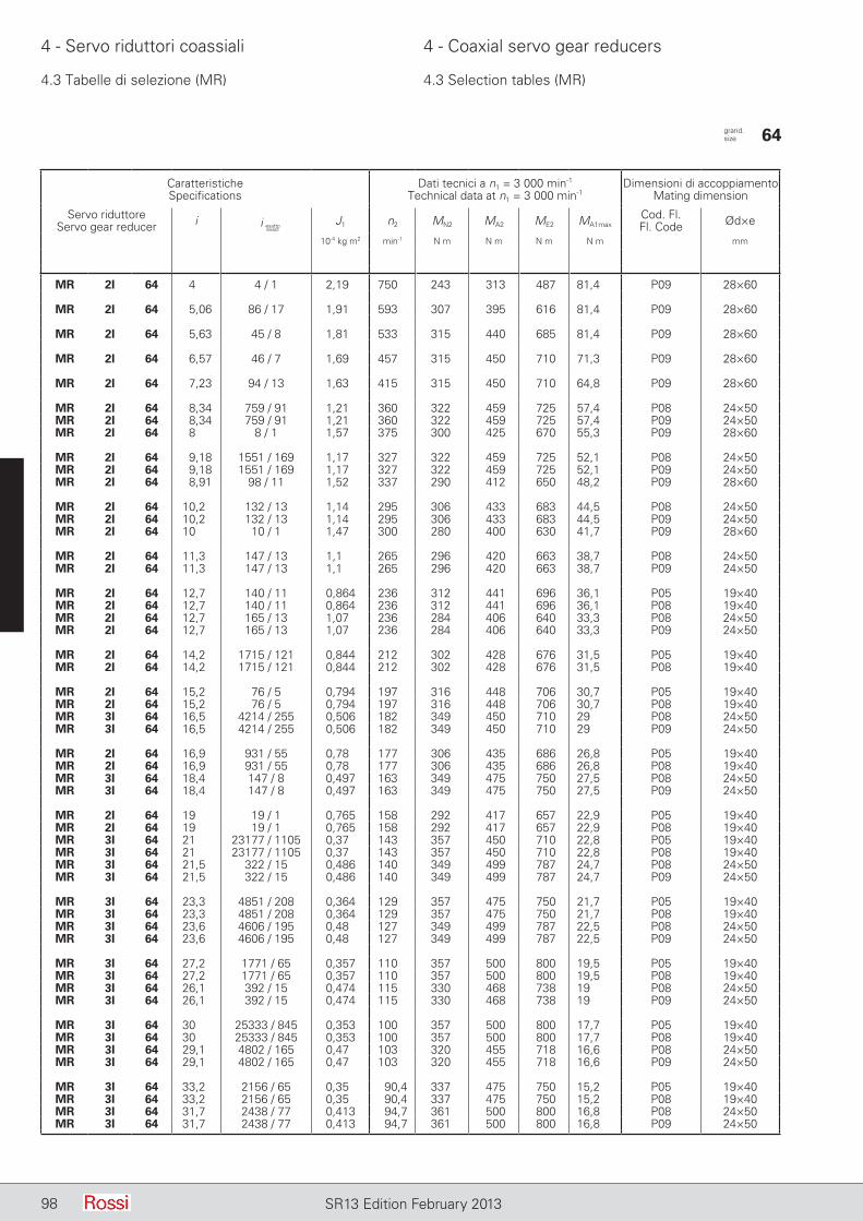
98 SR13 Edition February 2013
4 - Servo riduttori coassiali 4 - Coaxial servo gear reducers
4.3 Tabelle di selezione (MR) 4.3 Selection tables (MR)
CaratteristicheSpecifications
Dati tecnici a n1 = 3 000 min-1
Technical data at n1 = 3 000 min-1Dimensioni di accoppiamento
Mating dimension
Servo riduttoreServo gear reducer i J1 n2 MN2 MA2 ME2 MA1max
Cod. Fl.Fl. Code Ød×e
10-4 kg m2 min-1 N m N m N m N m mm
MR 2I 64 4 4 / 1 2,19 750 243 313 487 81,4 P09 28×60
MR 2I 64 5,06 86 / 17 1,91 593 307 395 616 81,4 P09 28×60
MR 2I 64 5,63 45 / 8 1,81 533 315 440 685 81,4 P09 28×60
MR 2I 64 6,57 46 / 7 1,69 457 315 450 710 71,3 P09 28×60
MR 2I 64 7,23 94 / 13 1,63 415 315 450 710 64,8 P09 28×60
MR 2I 64 8,34 759 / 91 1,21 360 322 459 725 57,4 P08 24×50MR 2I 64 8,34 759 / 91 1,21 360 322 459 725 57,4 P09 24×50MR 2I 64 8 8 / 1 1,57 375 300 425 670 55,3 P09 28×60
MR 2I 64 9,18 1551 / 169 1,17 327 322 459 725 52,1 P08 24×50MR 2I 64 9,18 1551 / 169 1,17 327 322 459 725 52,1 P09 24×50MR 2I 64 8,91 98 / 11 1,52 337 290 412 650 48,2 P09 28×60
MR 2I 64 10,2 132 / 13 1,14 295 306 433 683 44,5 P08 24×50MR 2I 64 10,2 132 / 13 1,14 295 306 433 683 44,5 P09 24×50MR 2I 64 10 10 / 1 1,47 300 280 400 630 41,7 P09 28×60
MR 2I 64 11,3 147 / 13 1,1 265 296 420 663 38,7 P08 24×50MR 2I 64 11,3 147 / 13 1,1 265 296 420 663 38,7 P09 24×50
MR 2I 64 12,7 140 / 11 0,864 236 312 441 696 36,1 P05 19×40MR 2I 64 12,7 140 / 11 0,864 236 312 441 696 36,1 P08 19×40MR 2I 64 12,7 165 / 13 1,07 236 284 406 640 33,3 P08 24×50MR 2I 64 12,7 165 / 13 1,07 236 284 406 640 33,3 P09 24×50
MR 2I 64 14,2 1715 / 121 0,844 212 302 428 676 31,5 P05 19×40MR 2I 64 14,2 1715 / 121 0,844 212 302 428 676 31,5 P08 19×40
MR 2I 64 15,2 76 / 5 0,794 197 316 448 706 30,7 P05 19×40MR 2I 64 15,2 76 / 5 0,794 197 316 448 706 30,7 P08 19×40MR 3I 64 16,5 4214 / 255 0,506 182 349 450 710 29 P08 24×50MR 3I 64 16,5 4214 / 255 0,506 182 349 450 710 29 P09 24×50
MR 2I 64 16,9 931 / 55 0,78 177 306 435 686 26,8 P05 19×40MR 2I 64 16,9 931 / 55 0,78 177 306 435 686 26,8 P08 19×40MR 3I 64 18,4 147 / 8 0,497 163 349 475 750 27,5 P08 24×50MR 3I 64 18,4 147 / 8 0,497 163 349 475 750 27,5 P09 24×50
MR 2I 64 19 19 / 1 0,765 158 292 417 657 22,9 P05 19×40MR 2I 64 19 19 / 1 0,765 158 292 417 657 22,9 P08 19×40MR 3I 64 21 23177 / 1105 0,37 143 357 450 710 22,8 P05 19×40MR 3I 64 21 23177 / 1105 0,37 143 357 450 710 22,8 P08 19×40MR 3I 64 21,5 322 / 15 0,486 140 349 499 787 24,7 P08 24×50MR 3I 64 21,5 322 / 15 0,486 140 349 499 787 24,7 P09 24×50
MR 3I 64 23,3 4851 / 208 0,364 129 357 475 750 21,7 P05 19×40MR 3I 64 23,3 4851 / 208 0,364 129 357 475 750 21,7 P08 19×40MR 3I 64 23,6 4606 / 195 0,48 127 349 499 787 22,5 P08 24×50MR 3I 64 23,6 4606 / 195 0,48 127 349 499 787 22,5 P09 24×50
MR 3I 64 27,2 1771 / 65 0,357 110 357 500 800 19,5 P05 19×40MR 3I 64 27,2 1771 / 65 0,357 110 357 500 800 19,5 P08 19×40MR 3I 64 26,1 392 / 15 0,474 115 330 468 738 19 P08 24×50MR 3I 64 26,1 392 / 15 0,474 115 330 468 738 19 P09 24×50
MR 3I 64 30 25333 / 845 0,353 100 357 500 800 17,7 P05 19×40MR 3I 64 30 25333 / 845 0,353 100 357 500 800 17,7 P08 19×40MR 3I 64 29,1 4802 / 165 0,47 103 320 455 718 16,6 P08 24×50MR 3I 64 29,1 4802 / 165 0,47 103 320 455 718 16,6 P09 24×50
MR 3I 64 33,2 2156 / 65 0,35 90,4 337 475 750 15,2 P05 19×40MR 3I 64 33,2 2156 / 65 0,35 90,4 337 475 750 15,2 P08 19×40MR 3I 64 31,7 2438 / 77 0,413 94,7 361 500 800 16,8 P08 24×50MR 3I 64 31,7 2438 / 77 0,413 94,7 361 500 800 16,8 P09 24×50
grand. size 64
i esattoexact
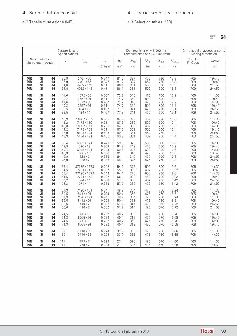
99SR13 Edition February 2013
4 - Servo riduttori coassiali 4 - Coaxial servo gear reducers
4.3 Tabelle di selezione (MR) 4.3 Selection tables (MR)
CaratteristicheSpecifications
Dati tecnici a n1 = 3 000 min-1
Technical data at n1 = 3 000 min-1Dimensioni di accoppiamento
Mating dimension
Servo riduttoreServo gear reducer i J1 n2 MN2 MA2 ME2 MA1max
Cod. Fl.Fl. Code Ød×e
10-4 kg m2 min-1 N m N m N m N m mm
MR 3I 64 36,9 2401 / 65 0,347 81,2 327 462 730 13,3 P05 19×40MR 3I 64 36,9 2401 / 65 0,347 81,2 327 462 730 13,3 P08 19×40MR 3I 64 34,8 4982 / 143 0,41 86,1 361 500 800 15,3 P08 24×50MR 3I 64 34,8 4982 / 143 0,41 86,1 361 500 800 15,3 P09 24×50
MR 3I 64 41,6 1372 / 33 0,267 72,2 343 475 750 12,2 P05 14×30MR 3I 64 40,2 3657 / 91 0,311 74,7 369 500 800 13,2 P05 19×40MR 3I 64 41,6 1372 / 33 0,267 72,2 343 475 750 12,2 P08 14×30MR 3I 64 40,2 3657 / 91 0,311 74,7 369 500 800 13,2 P08 19×40MR 3I 64 38,5 424 / 11 0,407 77,8 341 475 750 13,1 P08 24×50MR 3I 64 38,5 424 / 11 0,407 77,8 341 475 750 13,1 P09 24×50
MR 3I 64 46,3 16807 / 363 0,265 64,8 333 462 730 10,6 P05 14×30MR 3I 64 44,2 7473 / 169 0,31 67,8 369 500 800 12 P05 19×40MR 3I 64 46,3 16807 / 363 0,265 64,8 333 462 730 10,6 P08 14×30MR 3I 64 44,2 7473 / 169 0,31 67,8 369 500 800 12 P08 19×40MR 3I 64 42,9 5194 / 121 0,405 69,9 331 462 730 11,4 P08 24×50MR 3I 64 42,9 5194 / 121 0,405 69,9 331 462 730 11,4 P09 24×50
MR 3I 64 50,4 6095 / 121 0,243 59,6 376 500 800 10,6 P05 14×30MR 3I 64 48,9 636 / 13 0,308 61,3 348 475 750 10,3 P05 19×40MR 3I 64 50,4 6095 / 121 0,243 59,6 376 500 800 10,6 P08 14×30MR 3I 64 48,9 636 / 13 0,308 61,3 348 475 750 10,3 P08 19×40MR 3I 64 46,9 328 / 7 0,385 64 346 475 750 10,8 P08 24×50MR 3I 64 46,9 328 / 7 0,385 64 346 475 750 10,8 P09 24×50
MR 3I 64 55,4 87185 / 1573 0,242 54,1 376 500 800 9,6 P05 14×30MR 3I 64 54,5 7791 / 143 0,307 55 338 462 730 9,02 P05 19×40MR 3I 64 55,4 87185 / 1573 0,242 54,1 376 500 800 9,6 P08 14×30MR 3I 64 54,5 7791 / 143 0,307 55 338 462 730 9,02 P08 19×40MR 3I 64 52,2 574 / 11 0,383 57,5 336 462 730 9,42 P08 24×50MR 3I 64 52,2 574 / 11 0,383 57,5 336 462 730 9,42 P09 24×50
MR 3I 64 61,3 7420 / 121 0,24 48,9 354 475 750 8,24 P05 14×30MR 3I 64 59,5 5412 / 91 0,294 50,4 353 475 750 8,5 P05 19×40MR 3I 64 61,3 7420 / 121 0,24 48,9 354 475 750 8,24 P08 14×30MR 3I 64 59,5 5412 / 91 0,294 50,4 353 475 750 8,5 P08 19×40MR 3I 64 58,6 410 / 7 0,382 51,2 314 425 670 7,72 P08 24×50MR 3I 64 58,6 410 / 7 0,382 51,2 314 425 670 7,72 P09 24×50
MR 3I 64 74,5 820 / 11 0,232 40,2 360 475 750 6,78 P05 14×30MR 3I 64 74,3 6765 / 91 0,292 40,4 319 425 670 6,08 P05 19×40MR 3I 64 74,5 820 / 11 0,232 40,2 360 475 750 6,78 P08 14×30MR 3I 64 74,3 6765 / 91 0,292 40,4 319 425 670 6,08 P08 19×40
MR 3I 64 89 3116 / 35 0,224 33,7 365 475 750 5,68 P05 14×30MR 3I 64 89 3116 / 35 0,224 33,7 365 475 750 5,68 P08 14×30
MR 3I 64 111 779 / 7 0,223 27 328 425 670 4,06 P05 14×30MR 3I 64 111 779 / 7 0,223 27 328 425 670 4,06 P08 14×30
grand. size 64
i esattoexact

100 SR13 Edition February 2013
4 - Servo riduttori coassiali 4 - Coaxial servo gear reducers
4.3 Tabelle di selezione (MR) 4.3 Selection tables (MR)
CaratteristicheSpecifications
Dati tecnici a n1 = 3 000 min-1
Technical data at n1 = 3 000 min-1Dimensioni di accoppiamento
Mating dimension
Servo riduttoreServo gear reducer i J1 n2 MN2 MA2 ME2 MA1max
Cod. Fl.Fl. Code Ød×e
10-4 kg m2 min-1 N m N m N m N m mm
MR 2I 80 6,2 781 / 126 4,07 484 485 670 1 060 113 P10 28×60
MR 2I 80 7,13 3195 / 448 3,9 421 485 684 1 082 99,9 P10 28×60
MR 2I 80 7,95 3337 / 420 3,79 378 485 684 1 082 89,6 P10 28×60
MR 2I 80 9,36 852 / 91 3,63 320 485 684 1 082 76 P10 28×60
MR 2I 80 10,6 1775 / 168 3,54 284 485 684 1 082 67,4 P10 28×60
MR 2I 80 11,5 150 / 13 2,83 260 493 696 1 101 62,8 P08 24×50MR 2I 80 11,5 150 / 13 2,83 260 493 696 1 101 62,8 P09 24×50MR 2I 80 11,8 3621 / 308 3,46 255 483 682 1 078 60,4 P10 28×60
MR 2I 80 13 625 / 48 2,77 230 493 696 1 101 55,7 P08 24×50MR 2I 80 13 625 / 48 2,77 230 493 696 1 101 55,7 P09 24×50MR 2I 80 13 625 / 48 2,77 230 493 696 1 101 55,7 P10 28×60
MR 2I 80 14,5 1275 / 88 2,72 207 491 692 1 095 49,8 P08 24×50MR 2I 80 14,5 1275 / 88 2,72 207 491 692 1 095 49,8 P09 24×50MR 2I 80 14,5 1275 / 88 2,72 207 491 692 1 095 49,8 P10 28×60
MR 2I 80 16,1 225 / 14 2,37 187 502 709 1 121 45,9 P08 24×50MR 2I 80 16,1 225 / 14 2,37 187 502 709 1 121 45,9 P09 24×50MR 2I 80 16,3 65 / 4 2,67 185 484 670 1 060 42,9 P10 28×60MR 3I 80 16,1 1012 / 63 1,53 187 526 670 1 060 44,4 P10 28×60
MR 2I 80 17,9 1377 / 77 2,34 168 498 703 1 112 40,9 P08 24×50MR 2I 80 17,9 1377 / 77 2,34 168 498 703 1 112 40,9 P09 24×50MR 3I 80 18,5 1035 / 56 1,5 162 526 710 1 120 40,9 P10 28×60
MR 2I 80 20,1 702 / 35 2,3 150 488 670 1 060 34,8 P08 24×50MR 2I 80 20,1 702 / 35 2,3 150 488 670 1 060 34,8 P09 24×50MR 2I 80 19,9 2225 / 112 2,6 151 454 600 950 31,5 P10 28×60MR 3I 80 20,4 5566 / 273 1,11 147 536 670 1 060 35 P08 24×50MR 3I 80 20,4 5566 / 273 1,11 147 536 670 1 060 35 P09 24×50MR 3I 80 20,6 2162 / 105 1,49 146 526 741 1 173 38,3 P10 28×60
MR 3I 80 23,5 34155 / 1456 1,09 128 536 710 1 120 32,2 P08 24×50MR 3I 80 23,5 34155 / 1456 1,09 128 536 710 1 120 32,2 P09 24×50MR 3I 80 24,3 2208 / 91 1,46 124 526 741 1 173 32,5 P10 28×60
MR 2I 80 24,5 2403 / 98 2,26 122 456 600 950 25,5 P08 24×50MR 2I 80 24,5 2403 / 98 2,26 122 456 600 950 25,5 P09 24×50MR 3I 80 25,6 230 / 9 0,848 117 535 750 1 180 31,2 P08 19×40MR 3I 80 26,1 11891 / 455 1,08 115 536 750 1 180 30,5 P08 24×50MR 3I 80 25,6 230 / 9 0,848 117 535 750 1 180 31,2 P09 19×40MR 3I 80 26,1 11891 / 455 1,08 115 536 750 1 180 30,5 P09 24×50MR 3I 80 27,4 575 / 21 1,45 110 526 741 1 173 28,8 P10 28×60
MR 3I 80 30,8 36432 / 1183 1,07 97,4 536 750 1 180 25,9 P08 24×50MR 3I 80 30,8 36432 / 1183 1,07 97,4 536 750 1 180 25,9 P09 24×50
MR 3I 80 32,8 1081 / 33 0,832 91,6 547 750 1 180 24,4 P08 19×40MR 3I 80 34,8 6325 / 182 1,06 86,3 536 750 1 180 23 P08 24×50MR 3I 80 32,8 1081 / 33 0,832 91,6 547 750 1 180 24,4 P09 19×40MR 3I 80 34,8 6325 / 182 1,06 86,3 536 750 1 180 23 P09 24×50MR 3I 80 31,3 94 / 3 1,27 95,7 545 750 1 180 25,5 P10 28×60
MR 3I 80 38,6 5520 / 143 0,822 77,7 547 750 1 180 20,7 P08 19×40MR 3I 80 38,6 5520 / 143 0,822 77,7 547 750 1 180 20,7 P09 19×40MR 3I 80 36,9 480 / 13 1,26 81,2 545 750 1 180 21,6 P10 28×60
grand. size 80
i esattoexact
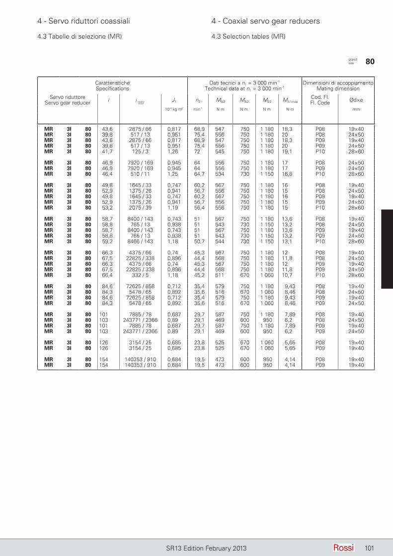
101SR13 Edition February 2013
4 - Servo riduttori coassiali 4 - Coaxial servo gear reducers
4.3 Tabelle di selezione (MR) 4.3 Selection tables (MR)
CaratteristicheSpecifications
Dati tecnici a n1 = 3 000 min-1
Technical data at n1 = 3 000 min-1Dimensioni di accoppiamento
Mating dimension
Servo riduttoreServo gear reducer i J1 n2 MN2 MA2 ME2 MA1max
Cod. Fl.Fl. Code Ød×e
10-4 kg m2 min-1 N m N m N m N m mm
MR 3I 80 43,6 2875 / 66 0,817 68,9 547 750 1 180 18,3 P08 19×40MR 3I 80 39,8 517 / 13 0,951 75,4 556 750 1 180 20 P08 24×50MR 3I 80 43,6 2875 / 66 0,817 68,9 547 750 1 180 18,3 P09 19×40MR 3I 80 39,8 517 / 13 0,951 75,4 556 750 1 180 20 P09 24×50MR 3I 80 41,7 125 / 3 1,26 72 545 750 1 180 19,1 P10 28×60
MR 3I 80 46,9 7920 / 169 0,945 64 556 750 1 180 17 P08 24×50MR 3I 80 46,9 7920 / 169 0,945 64 556 750 1 180 17 P09 24×50MR 3I 80 46,4 510 / 11 1,25 64,7 534 730 1 150 16,8 P10 28×60
MR 3I 80 49,8 1645 / 33 0,747 60,2 567 750 1 180 16 P08 19×40MR 3I 80 52,9 1375 / 26 0,941 56,7 556 750 1 180 15 P08 24×50MR 3I 80 49,8 1645 / 33 0,747 60,2 567 750 1 180 16 P09 19×40MR 3I 80 52,9 1375 / 26 0,941 56,7 556 750 1 180 15 P09 24×50MR 3I 80 53,2 2075 / 39 1,19 56,4 556 750 1 180 15 P10 28×60
MR 3I 80 58,7 8400 / 143 0,743 51 567 750 1 180 13,6 P08 19×40MR 3I 80 58,8 765 / 13 0,938 51 543 730 1 150 13,2 P08 24×50MR 3I 80 58,7 8400 / 143 0,743 51 567 750 1 180 13,6 P09 19×40MR 3I 80 58,8 765 / 13 0,938 51 543 730 1 150 13,2 P09 24×50MR 3I 80 59,2 8466 / 143 1,18 50,7 544 730 1 150 13,1 P10 28×60
MR 3I 80 66,3 4375 / 66 0,74 45,3 567 750 1 180 12 P08 19×40MR 3I 80 67,5 22825 / 338 0,896 44,4 568 750 1 180 11,8 P08 24×50MR 3I 80 66,3 4375 / 66 0,74 45,3 567 750 1 180 12 P09 19×40MR 3I 80 67,5 22825 / 338 0,896 44,4 568 750 1 180 11,8 P09 24×50MR 3I 80 66,4 332 / 5 1,18 45,2 511 670 1 060 10,7 P10 28×60
MR 3I 80 84,6 72625 / 858 0,712 35,4 579 750 1 180 9,43 P08 19×40MR 3I 80 84,3 5478 / 65 0,892 35,6 516 670 1 060 8,46 P08 24×50MR 3I 80 84,6 72625 / 858 0,712 35,4 579 750 1 180 9,43 P09 19×40MR 3I 80 84,3 5478 / 65 0,892 35,6 516 670 1 060 8,46 P09 24×50
MR 3I 80 101 7885 / 78 0,687 29,7 587 750 1 180 7,89 P08 19×40MR 3I 80 103 243771 / 2366 0,89 29,1 469 600 950 6,2 P08 24×50MR 3I 80 101 7885 / 78 0,687 29,7 587 750 1 180 7,89 P09 19×40MR 3I 80 103 243771 / 2366 0,89 29,1 469 600 950 6,2 P09 24×50
MR 3I 80 126 3154 / 25 0,685 23,8 525 670 1 060 5,65 P08 19×40MR 3I 80 126 3154 / 25 0,685 23,8 525 670 1 060 5,65 P09 19×40
MR 3I 80 154 140353 / 910 0,684 19,5 473 600 950 4,14 P08 19×40MR 3I 80 154 140353 / 910 0,684 19,5 473 600 950 4,14 P09 19×40
grand. size 80
i esattoexact
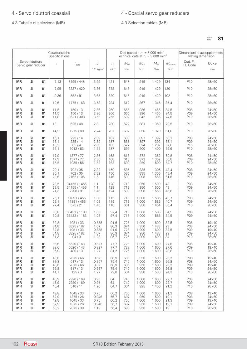
102 SR13 Edition February 2013
4 - Servo riduttori coassiali 4 - Coaxial servo gear reducers
4.3 Tabelle di selezione (MR) 4.3 Selection tables (MR)
CaratteristicheSpecifications
Dati tecnici a n1 = 3 000 min-1
Technical data at n1 = 3 000 min-1Dimensioni di accoppiamento
Mating dimension
Servo riduttoreServo gear reducer i J1 n2 MN2 MA2 ME2 MA1max
Cod. Fl.Fl. Code Ød×e
10-4 kg m2 min-1 N m N m N m N m mm
MR 2I 81 7,13 3195 / 448 3,99 421 643 919 1 429 134 P10 28×60
MR 2I 81 7,95 3337 / 420 3,86 378 643 919 1 429 120 P10 28×60
MR 2I 81 9,36 852 / 91 3,68 320 643 919 1 429 102 P10 28×60
MR 2I 81 10,6 1775 / 168 3,58 284 612 867 1 346 85,4 P10 28×60
MR 2I 81 11,5 150 / 13 2,86 260 655 936 1 455 84,5 P08 24×50MR 2I 81 11,5 150 / 13 2,86 260 655 936 1 455 84,5 P09 24×50MR 2I 81 11,8 3621 / 308 3,5 255 592 842 1 306 74,6 P10 28×60
MR 2I 81 13 625 / 48 2,8 230 622 881 1 369 70,5 P10 28×60
MR 2I 81 14,5 1275 / 88 2,74 207 602 856 1 329 61,6 P10 28×60
MR 2I 81 16,1 225 / 14 2,39 187 633 897 1 392 58,1 P08 24×50MR 2I 81 16,1 225 / 14 2,39 187 633 897 1 392 58,1 P09 24×50MR 2I 81 16,3 65 / 4 2,69 185 577 824 1 287 52,8 P10 28×60MR 3I 81 16,1 1012 / 63 1,55 187 699 900 1 400 59,6 P10 28×60
MR 2I 81 17,9 1377 / 77 2,36 168 613 872 1 352 50,8 P08 24×50MR 2I 81 17,9 1377 / 77 2,36 168 613 872 1 352 50,8 P09 24×50MR 3I 81 18,5 1035 / 56 1,52 162 699 950 1 500 54,7 P10 28×60
MR 2I 81 20,1 702 / 35 2,32 150 585 835 1 305 43,4 P08 24×50MR 2I 81 20,1 702 / 35 2,32 150 585 835 1 305 43,4 P09 24×50MR 3I 81 20,6 2162 / 105 1,5 146 699 998 1 553 51,6 P10 28×60
MR 3I 81 23,5 34155 / 1456 1,1 128 713 950 1 500 43 P08 24×50MR 3I 81 23,5 34155 / 1456 1,1 128 713 950 1 500 43 P09 24×50MR 3I 81 24,3 2208 / 91 1,48 124 699 998 1 553 43,8 P10 28×60
MR 3I 81 26,1 11891 / 455 1,09 115 713 1 000 1 585 40,7 P08 24×50MR 3I 81 26,1 11891 / 455 1,09 115 713 1 000 1 585 40,7 P09 24×50MR 3I 81 27,4 575 / 21 1,46 110 661 936 1 454 36,4 P10 28×60
MR 3I 81 30,8 36432 / 1183 1,08 97,4 713 1 000 1 585 34,5 P08 24×50MR 3I 81 30,8 36432 / 1183 1,08 97,4 713 1 000 1 585 34,5 P09 24×50
MR 3I 81 32,8 1081 / 33 0,838 91,6 728 1 000 1 600 32,5 P08 19×40MR 3I 81 34,8 6325 / 182 1,07 86,3 674 950 1 483 29 P08 24×50MR 3I 81 32,8 1081 / 33 0,838 91,6 728 1 000 1 600 32,5 P09 19×40MR 3I 81 34,8 6325 / 182 1,07 86,3 674 950 1 483 29 P09 24×50MR 3I 81 31,3 94 / 3 1,28 95,7 725 1 000 1 600 34 P10 28×60
MR 3I 81 38,6 5520 / 143 0,827 77,7 728 1 000 1 600 27,6 P08 19×40MR 3I 81 38,6 5520 / 143 0,827 77,7 728 1 000 1 600 27,6 P09 19×40MR 3I 81 36,9 480 / 13 1,27 81,2 725 1 000 1 600 28,8 P10 28×60
MR 3I 81 43,6 2875 / 66 0,82 68,9 686 950 1 500 23,2 P08 19×40MR 3I 81 39,8 517 / 13 0,957 75,4 740 1 000 1 600 26,8 P08 24×50MR 3I 81 43,6 2875 / 66 0,82 68,9 686 950 1 500 23,2 P09 19×40MR 3I 81 39,8 517 / 13 0,957 75,4 740 1 000 1 600 26,8 P09 24×50MR 3I 81 41,7 125 / 3 1,27 72,0 684 950 1 500 24,3 P10 28×60
MR 3I 81 46,9 7920 / 169 0,95 64 740 1 000 1 600 22,7 P08 24×50MR 3I 81 46,9 7920 / 169 0,95 64 740 1 000 1 600 22,7 P09 24×50MR 3I 81 46,4 510 / 11 1,26 64,7 664 925 1 450 21,2 P10 28×60
MR 3I 81 49,8 1645 / 33 0,75 60,2 755 1 000 1 600 21,3 P08 19×40MR 3I 81 52,9 1375 / 26 0,946 56,7 697 950 1 500 19,1 P08 24×50MR 3I 81 49,8 1645 / 33 0,75 60,2 755 1 000 1 600 21,3 P09 19×40MR 3I 81 52,9 1375 / 26 0,946 56,7 697 950 1 500 19,1 P09 24×50MR 3I 81 53,2 2075 / 39 1,19 56,4 698 950 1 500 19 P10 28×60
grand. size 81
i esattoexact

103SR13 Edition February 2013
4 - Servo riduttori coassiali 4 - Coaxial servo gear reducers
4.3 Tabelle di selezione (MR) 4.3 Selection tables (MR)
CaratteristicheSpecifications
Dati tecnici a n1 = 3 000 min-1
Technical data at n1 = 3 000 min-1Dimensioni di accoppiamento
Mating dimension
Servo riduttoreServo gear reducer i J1 n2 MN2 MA2 ME2 MA1max
Cod. Fl.Fl. Code Ød×e
10-4 kg m2 min-1 N m N m N m N m mm
MR 3I 81 58,7 8400 / 143 0,746 51 755 1 000 1 600 18,1 P08 19×40MR 3I 81 58,8 765 / 13 0,943 51 677 925 1 450 16,7 P08 24×50MR 3I 81 58,7 8400 / 143 0,746 51 755 1 000 1 600 18,1 P09 19×40MR 3I 81 58,8 765 / 13 0,943 51 677 925 1 450 16,7 P09 24×50MR 3I 81 59,2 8466 / 143 1,19 50,7 677 925 1 450 16,6 P10 28×60
MR 3I 81 66,3 4375 / 66 0,743 45,3 710 950 1 500 15,2 P08 19×40MR 3I 81 67,5 22825 / 338 0,9 44,4 711 950 1 500 15 P08 24×50MR 3I 81 66,3 4375 / 66 0,743 45,3 710 950 1 500 15,2 P09 19×40MR 3I 81 67,5 22825 / 338 0,9 44,4 711 950 1 500 15 P09 24×50MR 3I 81 66,4 332 / 5 1,18 45,2 632 850 1 320 13,6 P10 28×60
MR 3I 81 84,6 72625 / 858 0,714 35,4 724 950 1 500 11,9 P08 19×40MR 3I 81 84,3 5478 / 65 0,896 35,6 642 850 1 320 10,7 P08 24×50MR 3I 81 84,6 72625 / 858 0,714 35,4 724 950 1 500 11,9 P09 19×40MR 3I 81 84,3 5478 / 65 0,896 35,6 642 850 1 320 10,7 P09 24×50
MR 3I 81 101 7885 / 78 0,689 29,7 735 950 1 500 10 P08 19×40MR 3I 81 101 7885 / 78 0,689 29,7 735 950 1 500 10 P09 19×40
MR 3I 81 126 3154 / 25 0,687 23,8 659 850 1 320 7,17 P08 19×40MR 3I 81 126 3154 / 25 0,687 23,8 659 850 1 320 7,17 P09 19×40
grand. size 81
i esattoexact
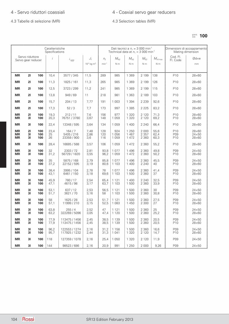
104 SR13 Edition February 2013
4 - Servo riduttori coassiali 4 - Coaxial servo gear reducers
4.3 Tabelle di selezione (MR) 4.3 Selection tables (MR)
CaratteristicheSpecifications
Dati tecnici a n1 = 3 000 min-1
Technical data at n1 = 3 000 min-1Dimensioni di accoppiamento
Mating dimension
Servo riduttoreServo gear reducer i J1 n2 MN2 MA2 ME2 MA1max
Cod. Fl.Fl. Code Ød×e
10-4 kg m2 min-1 N m N m N m N m mm
MR 2I 100 10,4 3577 / 345 11,5 289 985 1 369 2 199 138 P10 28×60
MR 2I 100 11,3 1825 / 161 11,3 265 985 1 369 2 199 126 P10 28×60
MR 2I 100 12,5 3723 / 299 11,2 241 985 1 369 2 199 115 P10 28×60
MR 2I 100 13,8 949 / 69 11 218 981 1 363 2 189 103 P10 28×60
MR 2I 100 15,7 204 / 13 7,77 191 1 003 1 394 2 239 92,6 P10 28×60
MR 2I 100 17,3 52 / 3 7,7 173 997 1 385 2 225 83,2 P10 28×60
MR 2I 100 19,3 212 / 11 7,6 156 977 1 320 2 120 71,3 P10 28×60MR 3I 100 20,3 76751 / 3780 3,67 148 1 059 1 320 2 120 69,2 P10 28×60
MR 3I 100 22,4 13348 / 595 3,64 134 1 059 1 400 2 240 66,4 P10 28×60
MR 2I 100 23,4 164 / 7 7,48 128 924 1 250 2 000 55,6 P10 28×60MR 3I 100 25 5405 / 216 2,86 120 1 056 1 467 2 357 62,4 P09 24×50MR 3I 100 26 23359 / 900 3,6 116 1 059 1 472 2 360 60,3 P10 28×60
MR 3I 100 28,4 16685 / 588 3,57 106 1 059 1 472 2 360 55,2 P10 28×60
MR 3I 100 32 2303 / 72 2,81 93,8 1 077 1 496 2 360 49,8 P09 24×50MR 3I 100 31,2 56729 / 1820 3,55 96,2 1 059 1 472 2 360 50,2 P10 28×60
MR 3I 100 35 5875 / 168 2,79 85,8 1 077 1 496 2 360 45,5 P09 24×50MR 3I 100 37,2 22152 / 595 3,19 80,6 1 103 1 400 2 240 40 P10 28×60
MR 3I 100 38,4 3995 / 104 2,78 78 1 077 1 496 2 360 41,4 P09 24×50MR 3I 100 43,1 6461 / 150 3,18 69,6 1 103 1 500 2 360 37 P10 28×60
MR 3I 100 45,9 780 / 17 2,54 65,4 1 121 1 400 2 240 32,5 P09 24×50MR 3I 100 47,1 4615 / 98 3,17 63,7 1 103 1 500 2 360 33,9 P10 28×60
MR 3I 100 53,1 637 / 12 2,53 56,5 1 121 1 500 2 360 30 P09 24×50MR 3I 100 51,7 3621 / 70 3,16 58 1 103 1 500 2 360 30,8 P10 28×60
MR 3I 100 58 1625 / 28 2,53 51,7 1 121 1 500 2 360 27,5 P09 24×50MR 3I 100 57,1 11999 / 210 3,15 52,5 1 083 1 450 2 300 27 P10 28×60
MR 3I 100 63,8 255 / 4 2,52 47 1 121 1 500 2 360 25 P09 24×50MR 3I 100 63,2 322269 / 5096 3,05 47,4 1 120 1 500 2 360 25,2 P10 28×60
MR 3I 100 77,9 113475 / 1456 2,45 38,5 1 139 1 500 2 360 20,5 P09 24×50MR 3I 100 77,9 113475 / 1456 2,45 38,5 1 139 1 500 2 360 20,5 P10 28×60
MR 3I 100 96,2 122553 / 1274 2,16 31,2 1 158 1 500 2 360 16,6 P09 24×50MR 3I 100 95,7 117925 / 1232 2,44 31,3 1 041 1 320 2 120 14,7 P10 28×60
MR 3I 100 118 127359 / 1078 2,16 25,4 1 050 1 320 2 120 11,9 P09 24×50
MR 3I 100 144 98523 / 686 2,16 20,9 991 1 250 2 000 9,26 P09 24×50
grand. size 100
i esattoexact
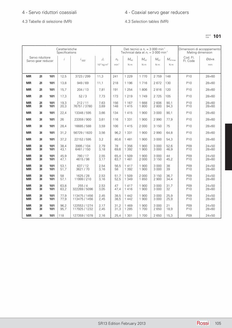
105SR13 Edition February 2013
4 - Servo riduttori coassiali 4 - Coaxial servo gear reducers
4.3 Tabelle di selezione (MR) 4.3 Selection tables (MR)
CaratteristicheSpecifications
Dati tecnici a n1 = 3 000 min-1
Technical data at n1 = 3 000 min-1Dimensioni di accoppiamento
Mating dimension
Servo riduttoreServo gear reducer i J1 n2 MN2 MA2 ME2 MA1max
Cod. Fl.Fl. Code Ød×e
10-4 kg m2 min-1 N m N m N m N m mm
MR 2I 101 12,5 3723 / 299 11,3 241 1 229 1 770 2 759 148 P10 28×60
MR 2I 101 13,8 949 / 69 11,1 218 1 196 1 716 2 672 130 P10 28×60
MR 2I 101 15,7 204 / 13 7,81 191 1 254 1 806 2 816 120 P10 28×60
MR 2I 101 17,3 52 / 3 7,73 173 1 219 1 749 2 725 105 P10 28×60
MR 2I 101 19,3 212 / 11 7,63 156 1 167 1 668 2 606 90,1 P10 28×60MR 3I 101 20,3 76751 / 3780 3,69 148 1 415 1 800 2 800 94,3 P10 28×60
MR 3I 101 22,4 13348 / 595 3,66 134 1 415 1 900 3 000 90,1 P10 28×60
MR 3I 101 26 23359 / 900 3,61 116 1 331 1 900 2 990 77,9 P10 28×60
MR 3I 101 28,4 16685 / 588 3,59 106 1 415 2 000 3 150 75 P10 28×60
MR 3I 101 31,2 56729 / 1820 3,56 96,2 1 331 1 900 2 990 64,8 P10 28×60
MR 3I 101 37,2 22152 / 595 3,2 80,6 1 481 1 900 3 000 54,3 P10 28×60
MR 3I 101 38,4 3995 / 104 2,79 78 1 356 1 900 3 000 52,6 P09 24×50MR 3I 101 43,1 6461 / 150 3,18 69,6 1 392 1 900 3 000 46,9 P10 28×60
MR 3I 101 45,9 780 / 17 2,55 65,4 1 509 1 900 3 000 44 P09 24×50MR 3I 101 47,1 4615 / 98 3,17 63,7 1 481 2 000 3 150 45,2 P10 28×60
MR 3I 101 53,1 637 / 12 2,54 56,5 1 417 1 900 3 000 38 P09 24×50MR 3I 101 51,7 3621 / 70 3,16 58 1 392 1 900 3 000 39 P10 28×60
MR 3I 101 58 1625 / 28 2,53 51,7 1 509 2 000 3 150 36,7 P09 24×50MR 3I 101 57,1 11999 / 210 3,16 52,5 1 349 1 850 2 900 34,4 P10 28×60
MR 3I 101 63,8 255 / 4 2,53 47 1 417 1 900 3 000 31,7 P09 24×50MR 3I 101 63,2 322269 / 5096 3,05 47,4 1 416 1 900 3 000 32 P10 28×60
MR 3I 101 77,9 113475 / 1456 2,45 38,5 1 442 1 900 3 000 25,9 P09 24×50MR 3I 101 77,9 113475 / 1456 2,45 38,5 1 442 1 900 3 000 25,9 P10 28×60
MR 3I 101 96,2 122553 / 1274 2,17 31,2 1 469 1 900 3 000 21 P09 24×50MR 3I 101 95,7 117925 / 1232 2,45 31,3 1 285 1 700 2 650 18,9 P10 28×60
MR 3I 101 118 127359 / 1078 2,16 25,4 1 301 1 700 2 650 15,3 P09 24×50
grand. size 101
i esattoexact

106 SR13 Edition February 2013
4 - Servo riduttori coassiali 4 - Coaxial servo gear reducers
4.4 Esecuzioni, dimensioni, forme costruttive e quantità d'olio (MR)
4.4 Designs, dimensions, mounting positions and oil quantities (MR)
MR 2I, 3I 32 ... 41
Dimensioni accoppiamento servo motoreServo motor coupling dimensions
Grand. Cod. fl. AC1 d e M1 N1 F1 Q1 A B C D E F G H K L M N P Q S T U V MassaSize Fl. code Ø Ø Ø Ø Ø h11 Ø Ø Ø Ø Mass
H7 h6 kgZ
32 P05 105 11 23 115 95 M08 4 115 53 20 16 30 9,5 98-881) 75 9,5 10 115 95 140 3 10 139 77 48 473
40 P02 90 11 23 100 80 M06 4 132 63 19 19 40 9,5 113 90 9,5 12 130 110 160 3,5 10 156 92 56 714 30
P05 105 14 30 115 95 M 8 419 40
P08 1202) 14 30 130 110 M 8 4,51202) 19 40 130 110 M 8 4,5
41 P02 90 14 30 100 80 M06 4 132 63 34 24 36 9,5 128-1131) 90 9,5 12 130 110 160 3,5 10 156 92 56 7
P05 105 14 30 115 95 M08 419 40
P08 1202) 14 30 130 110 M08 4,519 40
1) Rispettivamente quota battuta estremità d’albero e piano flangia.2) La quota AC1 è un Ø (≈ 1,4 AC1).
1) Dimensions of shaft end shoulder and flange surface respectively.2) Dimension AC1 is Ø (≈ 1,4 AC1).
Forme costruttive e quantità di grasso [kg]
Salvo diversa indicazione i servo riduttori vengono forniti nelle forme costruttive normale B3 o B5 le quali, in quanto normali, non vanno indicati nella designazione.
Mounting positions and grease quantities [kg] Grand. B3, B6 V5, V6 Size B7, B8
32, 81 0,14 0,25 40, 41 0,26 0,47
B5 V1, V3
32, 81 0,10 0,18 40, 41 0,19 0,35
Ese
cuzi
one
- Des
ign
PC1A
FC1A
B5 V1 V3
Unless otherwise stated, servo gear reducers are supplied in mounting position B3 or B5 which, being standard, are omitted from the designation.
B3 B6 B7 B8 V5 V6
EsecuzioneDesign normale (con piedi)standard (with feet) PC1A1) )
5)
EsecuzioneDesign normale (con flangia)standard (with flange) FC1A5)
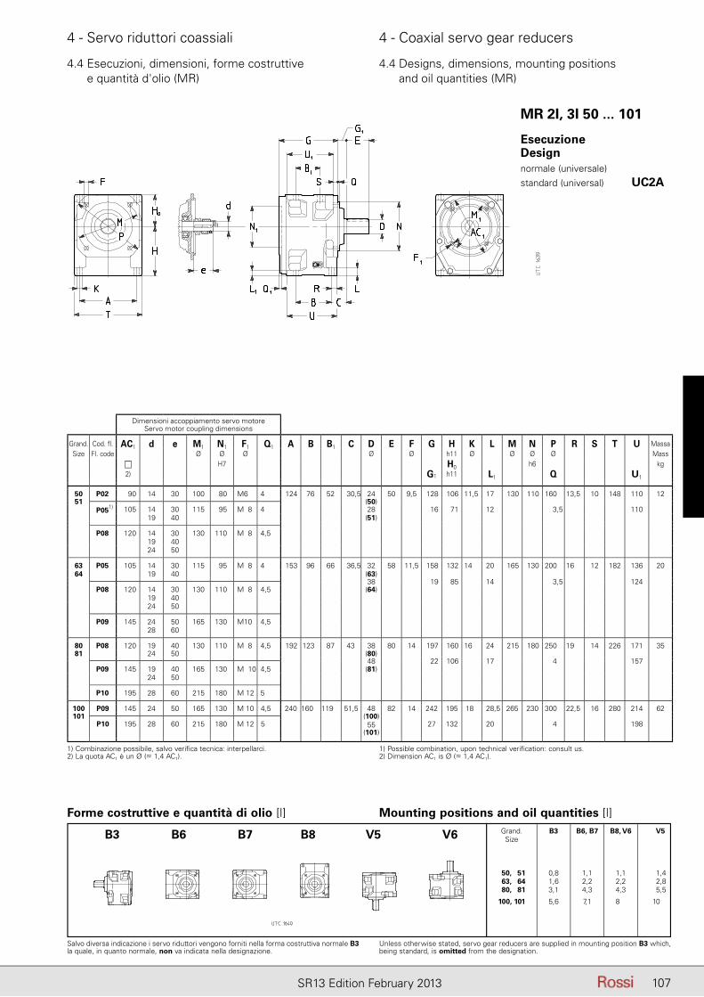
107SR13 Edition February 2013
4 - Servo riduttori coassiali 4 - Coaxial servo gear reducers
4.4 Esecuzioni, dimensioni, forme costruttive e quantità d'olio (MR)
4.4 Designs, dimensions, mounting positions and oil quantities (MR)
MR 2I, 3I 50 ... 101
Dimensioni accoppiamento servo motoreServo motor coupling dimensions
Grand. Cod. fl. AC1 d e M1 N1 F1 Q1 A B B1 C D E F G H K L M N P R S T U MassaSize Fl. code Ø Ø Ø Ø Ø h11 Ø Ø Ø Ø Mass
H7 H0 h6 kg2) G1 h11 L1 Q U1
50 P02 90 14 30 100 80 M6 4 124 76 52 30,5 24 50 9,5 128 106 11,5 17 130 110 160 13,5 10 148 110 1251 (50)
P051) 105 14 30 115 95 M08 4 28 16 71 12 3,5 11019 40 (51)
P08 120 14 30 130 110 M08 4,519 4024 50
63 P05 105 14 30 115 95 M08 4 153 96 66 36,5 32 58 11,5 158 132 14 20 165 130 200 16 12 182 136 2064 19 40 (63)
38 19 85 14 3,5 124P08 120 14 30 130 110 M08 4,5 (64)
19 4024 50
P09 145 24 50 165 130 M10 4,528 60
80 P08 120 19 40 130 110 M08 4,5 192 123 87 43 38 80 14 197 160 16 24 215 180 250 19 14 226 171 3581 24 50 (80)
48 22 106 17 4 157P09 145 19 40 165 130 M010 4,5 (81)
24 50
P10 195 28 60 215 180 M 12 5
100 P09 145 24 50 165 130 M 10 4,5 240 160 119 51,5 48 82 14 242 195 18 28,5 265 230 300 22,5 16 280 214 62101 (100)
P10 195 28 60 215 180 M 12 5 55 27 132 20 4 198(101)
Forme costruttive e quantità di olio [l]
Salvo diversa indicazione i servo riduttori vengono forniti nella forma costruttiva normale B3 la quale, in quanto normale, non va indicata nella designazione.
Unless otherwise stated, servo gear reducers are supplied in mounting position B3 which, being standard, is omitted from the designation.
Mounting positions and oil quantities [l] Grand. B3 B6, B7 B8, V6 V5 Size
50, 51 0,8 1,1 1,1 1,4 63, 64 1,6 2,2 2,2 2,8 80, 81 3,1 4,3 4,3 5,5
100, 101 5,6 7,1 8,0 10,0
B3 B6 B7 B8 V5 V6
1) Combinazione possibile, salvo verifica tecnica: interpellarci.2) La quota AC1 è un Ø (≈ 1,4 AC1).
1) Possible combination, upon technical verification: consult us.2) Dimension AC1 is Ø (≈ 1,4 AC1).
EsecuzioneDesign normale (universale)standard (universal) UC2A1) )
5)
108 SR13 Edition February 2013
4 - Servo riduttori coassiali 4 - Coaxial servo gear reducers
4.5 Carichi radiali Fr2 [N] o assiali Fa2 [N] sull'estremità d'albero lento
4.5 Radial loads Fr2 [N] or axial loads Fa2 [N] on low speed shaft end
Carichi assiali Fa2
Il valore ammissibile di Fa2 si trova nella colonna per la quale il senso di rotazione dell’albero lento (freccia bianca o freccia nera) e il sen so della forza assiale (freccia intera o freccia tratteggiata) corrispondono a quelli che si hanno sul servo riduttore. Il senso di rotazione e il senso della forza si stabiliscono guardando il servo riduttore da un punto qualunque, purché sia lo stesso per la rotazione e per la forza.Quando è possibile, mettersi nelle condizioni corrispondenti alla colonna di destra.
Carichi radiali Fr2
Quando il collegamento tra servo riduttore e macchina è realizzato con una trasmissione che genera carichi radiali sull’estremità d’albero, è ne cessario che questi siano minori o uguali a quelli indicati in tabella.Normalmente il carico radiale sull’estremità d’albero lento assume valori rilevanti; infatti si tende a realizzare la trasmissione tra servo riduttore e macchina con elevato rapporto di riduzione (per economizzare sul servo riduttore) e con diametri piccoli (per economizzare sulla trasmissione o per esigenze d’ingombro). Evidentemente la durata e l’usura (che influisce negativamente an che sugli ingranaggi) dei cuscinetti e la resistenza dell’asse lento pongono dei limiti al carico radiale ammissibile.L’elevato valore che può assumere il carico radiale e l’importanza di non superare i valori ammissibili richiedono di sfruttare al massimo le possibilità del servo riduttore.Pertanto i carichi radiali ammessi in tabella sono in funzione: del prodotto della velocità angolare n2 [min-1] per la durata dei cuscinetti Lh [h] richiesta, del senso di rotazione, della posizione angolare [°] del carico e del momento torcente M2 [N m] richiesto.I carichi radiali ammessi in tabella valgono per carichi agenti in mezzeria dell’estremità d’albero lento, cioè ad una distanza dalla battuta di 0,5 · E (E = lunghezza dell’estremità d’albero); se agiscono a 0,315 · E moltiplicarli per 1,25; se agiscono a 0,8 · E moltiplicarli per 0,8.
Axial loads Fa2
Permissible Fa2 is shown in the column where direction of rotation of low speed shaft (black or white arrow) and direction of the axial force (solid or broken arrow) correspond to those of the servo gear reducer in question. Direction of rotation and direction of force may be established viewing the servo gear reducer from any point, providing the same point adopted for both.Wherever possible, choose the load conditions corresponding the column on the right.
Radial loads Fr2
Radial loads generated on the shaft end by a drive connecting servo gear reducer and machine must be less than or equal to those given in the relevant table.Normally, radial loads on low speed shaft ends are considerable: in fact there is a tendency to connect the servo gear reducer to the machine by means of a transmission with high transmission ratio (economizing on the servo gear reducers) and with small diameters (economizing on the drive, and for requirements dictated by overall dimensions).Bearing life and wear (which also affect gears unfavourably) and low speed shaft strength, clearly impose limits on permissible radial load.The high value which radial load may take on, and the importance of not exceeding permissible values, make it necessary to take full advantage of the servo gear reducers’s possibilities.Permissible radial loads given in the table are therefore based on: the product of speed n2 [min-1] multiplied by bearing life Lh [h] required, the direction of rotation, the angular position [°] of the load and torque M2 [N m] required.Radial loads given in the table are valid for overhung loads on centre line of low speed shaft end, i.e. operating at a distance of 0,5 · E (E = shaft end length) from the shoulder. If operating at 0,315 · E multiply by 1,25; if operating at 0,8 · E multiply by 0,8.

109SR13 Edition February 2013
4 - Servo riduttori coassiali 4 - Coaxial servo gear reducers
4.5 Carichi radiali Fr2 [N] o assiali Fa2 [N] sull'estremità d'albero lento
4.5 Radial loads Fr2 [N] or axial loads Fa2 [N] on low speed shaft end
Per i casi di trasmissione più comuni, il carico radiale Fr2 ha il valore e la posizione angolare seguenti:
Radial load Fr2 for most common drives has the following value and angular position:
dove: P2 [kW] è la potenza richiesta all’uscita del riduttore, n2 [min-1] è la velocità angolare, d [m] è il diametro primitivo.
IMPORTANTE: 0° coincide con la semiretta parallela all’asse della vite e orientata come sopraraffigurato, pertanto segue la rotazione dell’asse della vite come sottoindicato.
where: P2 [kW] is power required at the output side of the gear re-ducer, n2 [min-1] is the speed, d [m] is the pitch diameter.
IMPORTANT: 0° coincides with a half line lying parallel to the worm axis, and oriented as shown above, and therefore it follows the rotation of the worm axis as shown below.
Fr2 = 28 650 · P2
d · n2 [daN]
per cinghia dentata
for timing belt drive
Fr2 = 47 750 · P2
d · n2 [daN]
per trasmissione a cinghie trapezoidali
for V-belt drive
Fr2 = 20 320 · P2
d · n2 [daN]
per trasmissione ad ingranaggio cilindrico diritto
for spur gear pair drive
RotazioneRotation
Nell'esecuzione con flangia (grandezze 32 ... 41), 0° è - in relazione alla forma simile della carcassa - nella stessa posizione.
In the flanged design (sizes 32 ... 41), 0° remains in the same position, as per the same shape of the housing.
-
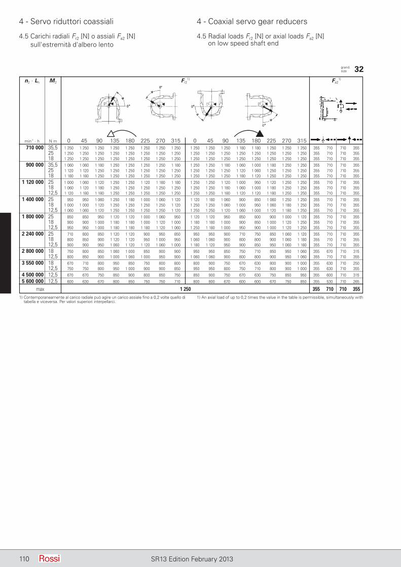
110 SR13 Edition February 2013
4 - Servo riduttori coassiali 4 - Coaxial servo gear reducers
4.5 Carichi radiali Fr2 [N] o assiali Fa2 [N] sull'estremità d'albero lento
4.5 Radial loads Fr2 [N] or axial loads Fa2 [N] on low speed shaft end
grand.size 32
n2 · Lh M2 Fr21) Fa2
1)
min-1 · h N m 0 45 90 135 180 225 270 315 0 45 90 135 180 225 270 315 710 000 35,5 1 250 1 250 1 250 1 250 1 250 1 250 1 250 1 250 1 250 1 250 1 250 1 180 1 180 1 250 1 250 1 250 355 710 710 355 25 1 250 1 250 1 250 1 250 1 250 1 250 1 250 1 250 1 250 1 250 1 250 1 250 1 250 1 250 1 250 1 250 355 710 710 355 18 1 250 1 250 1 250 1 250 1 250 1 250 1 250 1 250 1 250 1 250 1 250 1 250 1 250 1 250 1 250 1 250 355 710 710 355
900 000 35,5 1 060 1 060 1 180 1 250 1 250 1 250 1 250 1 180 1 250 1 250 1 180 1 060 1 000 1 180 1 250 1 250 355 710 710 355 25 1 120 1 120 1 250 1 250 1 250 1 250 1 250 1 250 1 250 1 250 1 250 1 120 1 060 1 250 1 250 1 250 355 710 710 355 18 1 180 1 180 1 250 1 250 1 250 1 250 1 250 1 250 1 250 1 250 1 250 1 180 1 120 1 250 1 250 1 250 355 710 710 355
1 120 000 25 1 000 1 060 1 120 1 250 1 250 1 120 1 180 1 180 1 250 1 250 1 120 1 000 950 1 120 1 250 1 250 355 710 710 355 18 1 060 1 120 1 180 1 250 1 250 1 250 1 250 1 250 1 250 1 250 1 180 1 060 1 000 1 180 1 250 1 250 355 710 710 355 12,5 1 120 1 180 1 180 1 250 1 250 1 250 1 250 1 250 1 250 1 250 1 180 1 120 1 120 1 180 1 250 1 250 355 710 710 355
1 400 000 25 950 950 1 060 1 250 1 180 1 000 1 060 1 120 1 120 1 180 1 060 900 850 1 060 1 250 1 250 355 710 710 355 18 1 000 1 000 1 120 1 250 1 250 1 250 1 250 1 120 1 250 1 250 1 060 1 000 950 1 060 1 180 1 250 355 710 710 355 12,5 1 060 1 060 1 120 1 250 1 250 1 250 1 250 1 120 1 250 1 250 1 120 1 060 1 000 1 120 1 180 1 250 355 710 710 355
1 800 000 25 850 850 950 1 120 1 120 1 000 1 060 950 1 120 1 120 950 850 800 900 1 000 1 120 355 710 710 355 18 900 900 1 000 1 180 1 180 1 000 1 120 1 000 1 180 1 180 1 000 900 850 1 000 1 120 1 250 355 710 710 355 12,5 950 950 1 000 1 180 1 180 1 180 1 120 1 060 1 250 1 180 1 000 950 900 1 000 1 120 1 250 355 710 710 355
2 240 000 25 710 800 850 1 120 1 120 900 950 850 950 950 900 710 750 850 1 060 1 120 355 710 710 355 18 800 850 900 1 120 1 120 950 1 000 950 1 060 1 060 900 800 800 900 1 060 1 180 355 710 710 355 12,5 900 900 950 1 060 1 120 1 120 1 060 1 000 1 180 1 120 950 900 850 950 1 060 1 180 355 710 710 355
2 800 000 18 750 800 850 1 060 1 000 850 900 900 950 950 850 750 710 850 950 1 060 355 670 710 315 12,5 800 850 900 1 000 1 060 1 000 950 900 1 060 1 060 900 800 800 900 950 1 060 355 710 710 355
3 550 000 18 670 710 800 950 850 750 800 800 800 900 750 670 630 800 900 1 000 355 630 710 250 12,5 750 750 800 950 1 000 900 900 850 950 950 800 750 710 800 900 1 000 355 630 710 355
4 500 000 12,5 670 670 750 850 900 800 850 750 850 900 750 670 630 750 850 950 355 600 710 315
5 600 000 12,5 600 630 670 800 850 750 750 710 800 800 670 600 600 670 750 850 355 530 710 265
max 1 250 355 710 710 3551) Contemporaneamente al carico radiale può agire un carico assiale fino a 0,2 volte quello di
tabella e viceversa. Per valori superiori interpellarci.1) An axial load of up to 0,2 times the value in the table is permissible, simultaneously with
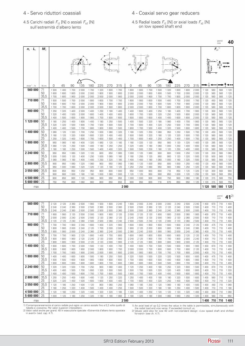
111SR13 Edition February 2013
4 - Servo riduttori coassiali 4 - Coaxial servo gear reducers
4.5 Carichi radiali Fr2 [N] o assiali Fa2 [N] sull'estremità d'albero lento
4.5 Radial loads Fr2 [N] or axial loads Fa2 [N] on low speed shaft end
grand. size 40 n2 · Lh M2 Fr2
1) Fa21)
min-1 · h N m 0 45 90 135 180 225 270 315 0 45 90 135 180 225 270 315 560 000 71 1 500 1 400 1 700 2 000 1 700 1 320 1 600 1 700 1 600 1 800 1 700 1 500 1 320 1 600 1 800 2 000 1 120 560 560 1 120 50 1 600 1 600 1 800 2 000 2 000 1 800 1 900 1 800 2 000 2 000 1 800 1 600 1 500 1 700 2 000 2 000 1 120 560 560 1 120 35,5 1 700 1 800 1 900 2 000 2 000 2 000 2 000 1 900 2 000 2 000 1 900 1 700 1 700 1 800 2 000 2 000 1 120 560 560 1 120
710 000 71 1 500 1 500 1 700 2 000 1 800 1 600 1 700 1 700 1 800 1 900 1 600 1 500 1 400 1 700 2 000 1 700 1 120 450 560 1 120 50 1 600 1 600 1 700 2 000 2 000 1 900 1 900 1 800 2 000 2 000 1 700 1 600 1 500 1 700 1 900 2 000 1 120 560 560 1 120 35,5 1 700 1 700 1 800 2 000 2 000 2 000 1 900 1 800 2 000 2 000 1 800 1 700 1 600 1 800 1 900 2 000 1 120 560 560 1 120
900 000 71 1 250 1 320 1 400 2 000 1 400 1 250 1 180 1 400 1 400 1 600 1 400 1 250 1 180 1 400 1 700 1 900 1 120 300 560 1 120 50 1 320 1 400 1 500 2 000 1 600 1 400 1 400 1 600 1 600 1 700 1 500 1 320 1 250 1 500 1 800 2 000 1 120 560 560 1 120 35,5 1 400 1 500 1 600 1 900 1 900 1 700 1 800 1 600 1 800 1 800 1 600 1 400 1 400 1 600 1 800 2 000 1 120 560 560 1 120
1 120 000 50 1 180 1 250 1 400 1 800 1 400 1 180 1 250 1 500 1 400 1 500 1 320 1 180 1 060 1 400 1 700 1 900 1 120 560 560 1 120 35,5 1 320 1 320 1 500 1 800 1 700 1 500 1 600 1 500 1 700 1 600 1 400 1 320 1 250 1 500 1 700 1 800 1 120 560 560 1 120 25 1 400 1 400 1 500 1 700 1 800 1 800 1 600 1 500 1 800 1 700 1 500 1 400 1 320 1 500 1 600 1 800 1 120 560 560 1 120
1 400 000 50 1 060 1 120 1 320 1 700 1 250 1 000 1 060 1 320 1 180 1 320 1 250 1 060 950 1 250 1 500 1 700 1 120 450 560 1 120 35,5 1 180 1 120 1 320 1 600 1 600 1 320 1 400 1 400 1 500 1 500 1 320 1 180 1 120 1 320 1 500 1 700 1 120 560 560 1 120 25 1 250 1 320 1 400 1 600 1 700 1 600 1 500 1 400 1 700 1 600 1 400 1 250 1 250 1 400 1 500 1 700 1 120 560 560 1 120
1 800 000 50 950 1 060 1 180 1 400 1 320 1 060 1 120 1 180 1 180 1 320 1 120 950 900 1 120 1 320 1 400 1 120 285 560 1 120 35,5 1 060 1 120 1 250 1 500 1 400 1 180 1 250 1 250 1 320 1 400 1 180 1 060 1 000 1 250 1 400 1 600 1 120 560 560 1 120 25 1 180 1 180 1 250 1 500 1 500 1 400 1 400 1 320 1 500 1 500 1 250 1 180 1 120 1 250 1 400 1 600 1 120 560 560 1 120
2 240 000 50 950 950 1 060 1 320 1 120 800 850 1 060 1 000 1 120 1 060 900 800 1 000 1 250 1 320 1 120 200 560 1 060 35,5 1 000 1 000 1 120 1 400 1 250 1 000 1 060 1 180 1 180 1 250 1 120 950 900 1 120 1 320 1 500 1 120 500 560 1 120 25 1 060 1 060 1 180 1 400 1 400 1 250 1 320 1 180 1 400 1 400 1 180 1 060 1 000 1 180 1 320 1 500 1 120 560 560 1 120
2 800 000 35,5 900 950 1 060 1 320 1 060 900 950 1 060 1 060 1 120 1 000 850 800 1 000 1 250 1 400 1 120 400 560 1 000 25 950 1 000 1 060 1 320 1 320 1 120 1 180 1 120 1 250 1 250 1 060 950 900 1 060 1 250 1 320 1 120 560 560 1 000
3 550 000 35,5 800 850 950 1 250 950 800 800 1 000 950 1 000 900 800 710 950 1 120 1 320 1 120 300 560 900 25 900 900 1 000 1 180 1 180 1 000 1 060 1 000 1 120 1 120 950 900 850 1 000 1 120 1 250 1 120 500 560 950
4 500 000 25 800 850 900 1 120 1 060 900 950 950 1 000 1 000 900 800 750 900 1 060 1 180 1 120 315 560 750
5 600 000 25 750 750 850 1 060 900 800 850 850 900 950 800 710 670 850 950 1 120 1 120 315 560 750
max 2 000 1 120 560 560 1 120
1) Contemporaneamente al carico radiale può agire un carico assiale fino a 0,2 volte quello di tabella e viceversa. Per valori superiori interpellarci.
2) Valori validi anche per grand. 40 in esecuzione speciale «Estremità d’albero lento spostata in avanti» (ved. cap. 4.7).
1) An axial load of up 0,2 times the value in the table is permissible, simultaneously with the radial load and vice versa. If exceeded consult us.
2) Values valid also for size 40 with non-standard design «Low speed shaft end shifted forward» (see ch. 4.7).
grand. size 412)
560 000 71 2 120 2 120 2 360 2 500 1 900 1 500 1 800 2 240 1 800 2 000 2 240 2 000 2 000 2 240 2 500 2 240 1 400 670 710 1 400 50 2 240 2 240 2 360 2 500 2 500 2 360 2 500 2 360 2 500 2 500 2 360 2 120 2 120 2 240 2 500 2 500 1 400 710 710 1 400 35,5 2 240 2 240 2 360 2 500 2 500 2 500 2 500 2 360 2 500 2 500 2 360 2 240 2 240 2 360 2 500 2 500 1 400 710 710 1 400
710 000 71 1 900 1 900 2 120 2 500 2 000 1 800 1 900 2 120 2 000 2 120 2 120 1 800 1 800 2 000 2 360 1 900 1 400 670 710 1 400 50 2 000 2 000 2 240 2 500 2 500 2 120 2 360 2 120 2 240 2 500 2 120 2 000 1 900 2 120 2 360 2 500 1 400 710 710 1 400 35,5 2 120 2 120 2 240 2 360 2 500 2 500 2 360 2 240 2 500 2 500 2 240 2 120 2 000 2 120 2 360 2 500 1 400 710 710 1 400
900 000 71 1 700 1 700 1 900 2 240 1 600 1 400 1 320 1 900 1 600 1 800 1 900 1 600 1 600 1 800 2 240 2 120 1 400 475 710 1 400 50 1 800 1 900 2 000 2 240 2 120 1 700 2 000 2 000 1 900 2 120 2 000 1 800 1 800 1 900 2 240 2 360 1 400 710 710 1 400 35,5 1 900 1 900 2 000 2 240 2 360 2 360 2 240 2 000 2 360 2 240 2 000 1 900 1 900 2 000 2 240 2 360 1 400 710 710 1 400
1 120 000 50 1 700 1 700 1 900 2 120 1 800 1 400 1 700 1 800 1 600 1 900 1 800 1 600 1 600 1 800 2 120 2 120 1 400 710 710 1 400 35,5 1 800 1 800 1 900 2 120 2 240 2 120 2 000 1 900 2 240 2 120 1 900 1 700 1 700 1 800 2 000 2 240 1 400 710 710 1 400 25 1 800 1 800 1 900 2 000 2 120 2 120 2 000 1 900 2 120 2 120 1 900 1 800 1 800 1 900 2 000 2 120 1 400 710 710 1 400
1 400 000 50 1 600 1 600 1 700 2 000 1 500 1 120 1 400 1 700 1 400 1 600 1 700 1 500 1 500 1 600 1 900 1 900 1 400 670 710 1 400 35,5 1 600 1 600 1 800 1 900 2 000 1 800 1 900 1 700 2 000 2 000 1 700 1 600 1 600 1 700 1 900 2 120 1 400 710 710 1 400 25 1 700 1 700 1 800 1 900 2 000 2 000 1 900 1 800 2 000 1 900 1 800 1 700 1 700 1 700 1 900 2 000 1 400 710 710 1 400
1 800 000 50 1 400 1 400 1 600 1 800 1 500 1 180 1 250 1 500 1 320 1 500 1 500 1 320 1 320 1 500 1 800 1 600 1 400 475 710 1 400 35,5 1 500 1 500 1 600 1 800 1 900 1 600 1 800 1 600 1 700 1 800 1 600 1 500 1 400 1 600 1 800 1 900 1 400 710 710 1 400 25 1 600 1 600 1 600 1 800 1 800 1 800 1 700 1 600 1 900 1 800 1 600 1 500 1 500 1 600 1 700 1 900 1 400 710 710 1 400
2 240 000 50 1 320 1 320 1 500 1 700 1 250 900 1 060 1 400 1 120 1 250 1 400 1 180 1 250 1 320 1 600 1 500 1 400 670 710 1 250 35,5 1 400 1 400 1 500 1 700 1 600 1 320 1 500 1 500 1 500 1 700 1 500 1 320 1 320 1 400 1 600 1 800 1 400 710 710 1 320 25 1 400 1 400 1 500 1 600 1 700 1 700 1 600 1 500 1 800 1 700 1 500 1 400 1 400 1 500 1 600 1 800 1 400 710 710 1 400
2 800 000 35,5 1 250 1 250 1 400 1 600 1 400 1 120 1 250 1 320 1 250 1 400 1 400 1 180 1 180 1 320 1 500 1 600 1 400 560 710 1 180 25 1 320 1 320 1 400 1 500 1 600 1 600 1 500 1 400 1 700 1 600 1 400 1 320 1 250 1 400 1 500 1 600 1 400 710 710 1 320
3 550 000 35,5 1 120 1 180 1 250 1 500 1 120 900 1 060 1 250 1 060 1 180 1 250 1 120 1 060 1 180 1 400 1 500 1 400 450 710 1 060 25 1 180 1 250 1 320 1 400 1 500 1 400 1 400 1 250 1 500 1 500 1 320 1 180 1 180 1 250 1 400 1 500 1 400 710 710 1 180
4 500 000 25 1 120 1 180 1 250 1 320 1 400 1 320 1 320 1 180 1 320 1 400 1 250 1 120 1 120 1 120 1 320 1 400 1 400 630 710 1 060
5 600 000 25 1 000 1 120 1 180 1 250 1 320 1 180 1 180 1 060 1 180 1 320 1 180 1 000 1 060 1 060 1 250 1 320 1 400 560 710 950
max 2 500 1 400 710 710 1 400
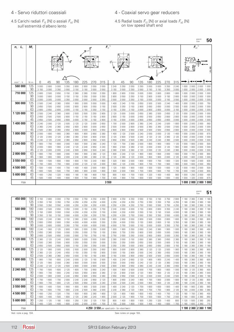
112 SR13 Edition February 2013
4 - Servo riduttori coassiali 4 - Coaxial servo gear reducers
4.5 Carichi radiali Fr2 [N] o assiali Fa2 [N] sull'estremità d'albero lento
4.5 Radial loads Fr2 [N] or axial loads Fa2 [N] on low speed shaft end
grand. size 50 n2 · Lh M2 Fr2
1) Fa21)
min-1 · h N m 0 45 90 135 180 225 270 315 0 45 90 135 180 225 270 315 560 000 125 3 000 2 800 3 000 3 350 2 800 2 800 3 550 3 550 2 240 3 350 3 550 3 350 3 000 3 000 3 350 2 240 1 000 2 000 2 000 1 000 90 3 150 3 000 3 350 3 550 3 150 3 150 3 550 3 550 3 150 3 550 3 350 3 550 3 150 3 150 3 350 3 000 1 000 2 000 2 000 1 000
710 000 125 2 800 2 500 2 650 3 150 2 360 2 360 3 550 3 350 1 800 2 800 3 550 3 000 2 650 2 800 2 800 1 800 1 000 2 000 2 000 1 000 90 3 000 2 800 3 000 3 150 3 150 3 350 3 550 3 350 2 800 3 550 3 350 3 150 2 800 3 000 3 150 2 800 1 000 2 000 2 000 1 000 63 3 000 3 000 3 000 3 350 3 550 3 550 3 550 3 350 3 550 3 550 3 350 3 150 3 000 3 000 3 150 3 550 1 000 2 000 2 000 1 000
900 000 125 2 500 2 240 2 360 2 650 1 900 2 000 3 000 3 000 1 400 2 240 3 150 2 650 2 500 2 500 2 240 1 400 1 000 2 000 2 000 750 90 2 650 2 500 2 650 3 000 2 800 2 800 3 550 3 150 2 500 3 350 3 150 2 800 2 650 2 650 3 000 2 500 1 000 2 000 2 000 1 000 63 2 800 2 650 2 800 3 000 3 150 3 150 3 350 3 150 3 150 3 350 3 150 3 000 2 800 2 800 3 000 3 150 1 000 2 000 2 000 1 000
1 120 000 90 2 500 2 240 2 360 2 800 2 500 2 500 3 350 2 800 2 120 3 000 3 000 2 650 2 360 2 500 2 650 2 120 1 000 2 000 2 000 1 000 63 2 650 2 500 2 500 2 800 3 150 3 150 3 150 2 800 2 800 3 150 3 000 2 650 2 500 2 650 2 800 2 800 1 000 2 000 2 000 1 000 45 2 650 2 500 2 650 2 800 3 000 3 150 3 150 2 800 3 150 3 000 3 000 2 800 2 650 2 650 2 800 3 000 1 000 2 000 2 000 1 000
1 400 000 90 2 240 2 000 2 120 2 500 2 120 2 120 3 000 2 650 1 700 2 500 2 800 2 360 2 240 2 240 2 500 1 800 1 000 2 000 2 000 950 63 2 360 2 240 2 360 2 650 2 800 2 800 3 000 2 650 2 500 3 000 2 800 2 500 2 360 2 360 2 500 2 500 1 000 2 000 2 000 1 000 45 2 500 2 360 2 360 2 650 2 800 3 000 2 800 2 650 2 800 2 800 2 650 2 500 2 500 2 500 2 650 2 800 1 000 2 000 2 000 1 000
1 800 000 90 2 000 1 800 1 900 2 360 1 800 1 800 2 650 2 360 1 400 2 120 2 500 2 240 2 000 2 000 2 120 1 400 1 000 2 000 2 000 670 63 2 120 2 000 2 120 2 360 2 360 2 500 2 800 2 500 2 120 2 800 2 500 2 240 2 120 2 120 2 360 2 120 1 000 2 000 2 000 1 000 45 2 240 2 120 2 240 2 360 2 650 2 800 2 650 2 500 2 650 2 650 2 500 2 360 2 240 2 240 2 360 2 500 1 000 2 000 2 000 1 000
2 240 000 90 1 800 1 700 1 800 2 000 1 500 1 500 2 360 2 240 1 120 1 700 2 360 2 000 1 800 1 900 1 800 1 120 1 000 1 800 2 000 500 63 2 000 1 800 1 900 2 240 2 120 2 240 2 650 2 240 1 900 2 500 2 360 2 120 2 000 2 000 2 120 1 900 1 000 1 800 2 000 1 000 45 2 120 2 000 2 000 2 240 2 500 2 650 2 500 2 240 2 360 2 500 2 360 2 120 2 000 2 120 2 240 2 360 1 000 2 000 2 000 1 000
2 800 000 63 1 800 1 700 1 800 2 000 1 900 1 900 2 360 2 120 1 600 2 240 2 120 1 900 1 800 1 800 2 000 1 600 1 000 1 700 2 000 800 45 1 900 1 800 1 900 2 000 2 240 2 360 2 360 2 120 2 120 2 360 2 120 2 000 1 900 1 900 2 000 2 120 1 000 1 800 2 000 1 000
3 550 000 63 1 600 1 500 1 600 1 900 1 600 1 700 2 240 1 900 1 320 1 900 2 000 1 800 1 600 1 700 1 800 1 320 1 000 1 500 2 000 630 45 1 700 1 600 1 700 1 900 2 000 2 120 2 120 2 000 1 900 2 120 2 000 1 800 1 700 1 700 1 900 1 900 1 000 1 600 2 000 950
4 500 000 63 1 500 1 400 1 400 1 700 1 400 1 400 2 000 1 800 1 120 1 600 1 900 1 600 1 500 1 500 1 600 1 120 1 000 1 400 2 000 500 45 1 600 1 500 1 500 1 700 1 800 1 900 2 000 1 800 1 600 2 000 1 900 1 700 1 600 1 600 1 700 1 700 1 000 1 500 2 000 800
5 600 000 63 1 400 1 250 1 320 1 600 1 180 1 180 1 800 1 700 900 1 400 1 700 1 500 1 320 1 400 1 400 900 1 000 1 250 2 000 400 45 1 500 1 400 1 400 1 600 1 600 1 700 1 900 1 700 1 400 1 900 1 700 1 600 1 500 1 500 1 600 1 400 1 000 1 320 2 000 670
max 3 550 1 000 2 000 2 000 1 000
Ved. note a pag. 104. See notes on page 104.
grand. size 51 450 000 180 3 150 2 800 3 000 3 750 3 550 3 750 4 250 4 000 2 800 4 250 4 250 3 550 3 150 3 150 3 750 2 800 1 180 2 360 2 360 1 180 125 3 350 3 150 3 350 3 750 4 250 4 250 4 250 4 000 4 250 4 250 4 250 3 750 3 350 3 350 3 750 4 250 1 180 2 360 2 360 1 180 90 3 550 3 350 3 550 4 000 4 250 4 250 4 250 4 000 4 250 4 250 4 250 3 750 3 550 3 550 3 750 4 250 1 180 2 360 2 360 1 180
560 000 180 2 800 2 500 2 650 3 350 3 000 3 150 4 250 3 750 2 240 3 550 4 000 3 150 2 800 2 800 3 350 2 240 1 180 2 360 2 360 1 180 125 3 150 2 800 3 000 3 550 4 250 4 250 4 250 3 750 4 000 4 250 4 000 3 350 3 150 3 150 3 550 4 000 1 180 2 360 2 360 1 180 90 3 350 3 150 3 150 3 550 4 000 4 250 4 250 3 750 4 250 4 250 3 750 3 550 3 350 3 350 3 550 4 000 1 180 2 360 2 360 1 180
710 000 180 2 500 2 240 2 360 3 150 2 360 2 500 4 000 3 350 1 600 2 650 3 550 2 800 2 500 2 650 2 800 1 600 1 180 2 360 2 360 800 125 2 800 2 650 2 800 3 350 4 000 4 000 4 000 3 350 3 350 4 000 3 550 3 150 2 800 2 800 3 150 3 350 1 180 2 360 2 360 1 180 90 3 000 2 800 3 000 3 350 3 750 4 000 4 000 3 550 4 000 3 750 3 550 3 150 3 000 3 000 3 350 3 750 1 180 2 360 2 360 1 180
900 000 180 2 240 1 900 2 120 2 800 1 900 2 000 3 350 3 000 1 000 1 900 3 350 2 650 2 240 2 360 1 900 1 000 1 180 2 360 2 360 450 125 2 650 2 360 2 500 3 000 3 350 3 550 3 750 3 150 2 800 3 750 3 350 2 800 2 500 2 650 3 000 2 800 1 180 2 360 2 360 1 180 90 2 800 2 500 2 650 3 000 3 550 3 750 3 750 3 150 3 750 3 550 3 350 3 000 2 800 2 800 3 000 3 350 1 180 2 360 2 360 1 180
1 120 000 125 2 360 2 120 2 240 2 800 2 800 3 000 3 500 3 000 2 360 3 550 3 150 2 650 2 360 2 360 2 650 2 360 1 180 2 360 2 360 1 180 90 2 500 2 360 2 500 2 800 3 350 3 550 3 350 3 000 3 350 3 350 3 000 2 650 2 500 2 500 2 800 3 150 1 180 2 360 2 360 1 180 63 2 650 2 500 2 650 2 800 3 150 3 350 3 350 3 000 3 350 3 350 3 000 2 800 2 650 2 650 2 800 3 150 1 180 2 360 2 360 1 180
1 400 000 125 2 120 1 900 2 000 2 500 2 500 2 500 3 350 2 650 1 900 3 000 2 800 2 360 2 120 2 120 2 500 1 900 1 180 2 360 2 360 900 90 2 360 2 120 2 240 2 650 3 150 3 350 3 150 2 800 3 000 3 150 2 800 2 500 2 240 2 360 2 650 3 000 1 180 2 360 2 360 1 180 63 2 500 2 360 2 360 2 650 3 000 3 150 3 150 2 800 3 150 3 000 2 800 2 650 2 500 2 500 2 650 3 000 1 180 2 360 1 360 1 180
1 800 000 125 1 900 1 700 1 800 2 240 2 000 2 120 3 150 2 500 1 400 2 240 2 650 2 120 1 900 1 900 2 240 1 400 1 180 2 360 2 360 600 90 2 120 1 900 2 000 2 360 2 800 3 000 3 000 2 500 2 500 3 000 2 650 2 240 2 120 2 120 2 360 2 500 1 180 2 360 2 360 1 180 63 2 240 2 120 2 120 2 500 2 800 3 000 2 800 2 500 2 800 2 800 2 650 2 360 2 240 2 240 2 360 2 650 1 180 2 360 2 360 1 180
2 240 000 125 1 700 1 500 1 600 2 120 1 600 1 700 2 650 2 240 1 000 1 800 2 500 2 000 1 700 1 800 1 800 1 000 1 180 2 120 2 360 400 90 1 900 1 700 1 800 2 240 2 500 2 650 2 800 2 360 2 120 2 800 2 500 2 120 1 900 1 900 2 120 2 120 1 180 2 360 2 360 1 000 63 2 000 1 900 2 000 2 240 2 650 2 800 2 650 2 360 2 650 2 650 2 500 2 120 2 000 2 000 2 240 2 500 1 180 2 360 2 360 1 180
2 800 000 90 1 700 1 600 1 700 2 000 2 240 2 240 2 650 2 120 1 800 2 650 2 240 1 900 1 700 1 800 2 000 1 800 1 180 2 120 2 360 800 63 1 900 1 700 1 800 2 120 2 500 2 650 2 500 2 240 2 500 2 500 2 240 2 000 1 900 1 900 2 120 2 360 1 180 2 240 2 360 1 180
3 550 000 90 1 600 1 400 1 500 1 900 1 800 1 900 2 500 2 000 1 400 2 240 2 120 1 700 1 600 1 600 1 800 1 400 1 180 1 900 2 360 560 63 1 700 1 600 1 700 1 900 2 240 2 500 2 360 2 000 2 240 2 360 2 120 1 800 1 700 1 700 1 900 2 120 1 180 2 000 2 360 1 060
4 500 000 90 1 400 1 250 1 320 1 700 1 500 1 600 2 360 1 800 1 120 1 800 1 900 1 600 1 400 1 400 1 700 1 120 1 180 1 700 2 360 400 63 1 600 1 400 1 500 1 800 2 120 2 360 2 240 1 900 2 000 2 120 1 900 1 700 1 500 1 600 1 700 2 000 1 180 1 800 2 360 850
5 600 000 90 1 250 1 120 1 180 1 600 1 250 1 250 2 120 1 700 800 1 400 1 800 1 500 1 250 1 320 1 400 800 1 120 1 500 2 360 250 63 1 400 1 320 1 400 1 600 2 000 2 000 2 000 1 700 1 700 2 000 1 800 1 500 1 400 1 400 1 600 1 700 1 180 1 600 2 360 710
max 4 250 (3 550 per «piedi corti» - for «short feet») 1 180 2 360 2 360 1 180
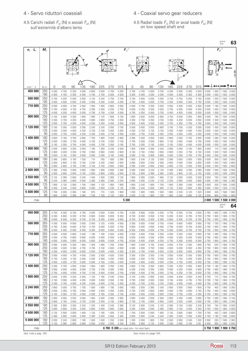
113SR13 Edition February 2013
4 - Servo riduttori coassiali 4 - Coaxial servo gear reducers
4.5 Carichi radiali Fr2 [N] o assiali Fa2 [N] sull'estremità d'albero lento
4.5 Radial loads Fr2 [N] or axial loads Fa2 [N] on low speed shaft end
grand. size 63 n2 · Lh M2 Fr2
1) Fa21)
min-1 · h N m 0 45 90 135 180 225 270 315 0 45 90 135 180 225 270 315 450 000 250 4 250 4 750 5 300 4 500 2 800 3 000 4 750 4 250 3 750 4 750 4 000 3 750 4 250 5 300 5 300 4 000 3 000 1 500 1 500 3 000 180 4 500 4 750 5 300 5 300 4 750 4 750 5 000 4 500 5 300 5 000 4 250 4 250 4 500 5 300 5 300 5 300 3 000 1 500 1 500 3 000
560 000 250 3 750 4 250 5 000 3 550 2 120 2 240 3 750 3 750 3 150 4 500 3 550 3 350 3 750 4 750 5 000 3 150 3 000 1 500 1 500 3 000 180 4 000 4 500 5 000 5 300 4 000 4 250 4 500 4 250 4 750 4 500 4 000 3 750 4 250 5 000 5 300 4 750 3 000 1 500 1 500 3 000
710 000 250 3 550 4 000 4 750 2 500 1 500 1 500 2 800 3 550 2 500 3 750 3 350 3 000 3 550 4 500 4 000 2 500 3 000 1 180 1 500 3 000 180 3 750 4 000 4 750 4 750 3 350 3 350 4 250 3 750 4 000 4 250 3 550 3 550 3 750 4 500 5 000 4 250 3 000 1 500 1 500 3 000 125 4 000 4 250 4 500 5 000 4 750 4 750 4 250 4 000 4 750 4 250 4 000 3 750 4 000 4 500 5 000 5 000 3 000 1 500 1 500 3 000
900 000 250 3 150 3 550 4 250 1 600 1 060 1 120 1 800 3 150 1 800 3 000 3 000 2 800 3 150 4 000 3 350 1 900 3 000 750 1 500 3 000 180 3 350 3 750 4 250 4 000 2 800 2 800 3 750 3 350 3 350 3 750 3 350 3 150 3 350 4 250 5 000 3 550 3 000 1 500 1 500 3 000 125 3 550 3 750 4 250 4 500 4 250 4 250 4 000 3 550 4 500 4 000 3 550 3 350 3 750 4 250 4 750 4 750 3 000 1 500 1 500 3 000
1 120 000 180 3 150 3 350 4 000 3 350 2 240 2 240 3 550 3 150 3 000 3 550 3 000 2 800 3 150 3 750 4 250 3 000 3 000 1 400 1 500 3 000 125 3 350 3 550 4 000 4 250 3 750 3 750 3 550 3 350 4 250 3 750 3 150 3 150 3 350 4 000 4 500 4 250 3 000 1 500 1 500 3 000 90 3 550 3 750 4 000 4 250 4 250 4 000 3 750 3 550 4 000 3 750 3 350 3 350 3 550 4 000 4 250 4 250 3 000 1 500 1 500 3 000
1 400 000 180 2 800 3 150 3 750 2 650 1 700 1 800 3 000 2 800 2 360 3 350 2 650 2 500 2 800 3 550 3 750 2 500 3 000 1 060 1 500 3 000 125 3 000 3 350 3 750 4 000 3 150 3 150 3 350 3 150 3 750 3 350 3 000 2 800 3 150 3 550 4 000 3 750 3 000 1 500 1 500 3 000 90 3 150 3 350 3 750 4 000 4 000 3 750 3 350 3 150 3 750 3 350 3 150 3 000 3 150 3 550 4 000 4 000 3 000 1 500 1 500 3 000
1 800 000 180 2 500 2 800 3 350 2 000 1 180 1 250 2 240 2 500 1 900 2 800 2 360 2 240 2 650 3 350 3 150 1 900 3 000 710 1 500 2 800 125 2 800 3 000 3 350 3 750 2 650 2 650 3 000 2 800 3 150 3 150 2 650 2 650 2 800 3 350 3 750 3 150 3 000 1 500 1 500 3 000 90 3 000 3 150 3 350 3 550 3 550 3 350 3 150 3 000 3 550 3 150 2 800 2 800 3 000 3 350 3 750 3 750 3 000 1 500 1 500 3 000
2 240 000 180 2 360 2 650 3 150 1 320 710 750 1 500 2 360 1 500 2 240 2 120 2 000 2 360 3 000 2 500 1 500 3 000 500 1 500 2 650 125 2 500 2 800 3 150 3 150 2 240 2 240 2 800 2 500 2 650 2 800 2 500 2 360 2 650 3 000 3 550 2 800 3 000 1 250 1 500 2 800 90 2 650 2 800 3 150 3 350 3 150 3 150 2 800 2 650 3 350 3 000 2 650 2 500 2 650 3 150 3 350 3 550 3 000 1 500 1 500 2 800
2 800 000 125 2 360 2 500 3 000 2 650 1 800 1 900 2 650 2 360 2 360 2 650 2 240 2 120 2 360 2 800 3 350 2 360 3 000 1 000 1 500 2 500 90 2 500 2 650 3 000 3 150 2 800 2 800 2 650 2 500 3 150 2 650 2 360 2 360 2 500 2 800 3 150 3 150 3 000 1 500 1 500 2 650
3 550 000 125 2 120 2 360 2 800 2 240 1 400 1 500 2 360 2 120 1 900 2 360 2 000 1 900 2 120 2 650 3 000 2 000 3 000 750 1 500 2 240 90 2 240 2 360 2 650 3 000 2 360 2 360 2 500 2 240 2 650 2 500 2 240 2 120 2 240 2 650 3 000 2 800 3 000 1 250 1 500 2 360
4 500 000 125 1 900 2 120 2 500 1 700 1 060 1 120 1 900 1 900 1 600 2 240 1 800 1 700 1 900 2 360 2 500 1 600 3 000 530 1 500 2 000 90 2 000 2 240 2 500 2 800 2 000 2 000 2 240 2 120 2 360 2 240 2 000 1 900 2 120 2 500 2 800 2 360 3 000 1 000 1 500 2 120
5 600 000 125 1 700 2 000 2 360 1 180 670 710 1 320 1 800 1 250 1 900 1 600 1 500 1 800 2 240 2 120 1 320 3 000 400 1 500 1 900 90 1 900 2 000 2 360 2 360 1 700 1 700 2 120 1 900 2 000 2 120 1 800 1 700 1 900 2 240 2 650 2 120 3 000 800 1 500 1 900
max 5 300 3 000 1 500 1 500 3 000
Ved. note a pag. 104. See notes on page 104.
grand. size 64 450 000 355 4 750 5 300 6 700 4 750 3 000 3 000 5 300 4 750 4 250 5 600 4 500 4 250 4 750 6 300 6 700 4 500 3 750 1 900 1 900 3 750 250 5 300 5 600 6 300 6 700 5 600 5 600 5 600 5 300 6 700 6 000 5 000 4 750 5 300 6 300 6 700 6 700 3 750 1 900 1 900 3 750 180 5 600 6 000 6 300 6 700 6 700 6 300 6 000 5 600 6 700 6 000 5 300 5 300 5 600 6 300 6 700 6 700 3 750 1 900 1 900 3 750
560 000 355 4 250 5 000 6 000 3 550 2 000 2 120 4 000 4 500 3 350 5 000 4 000 3 750 4 500 5 600 5 600 3 550 3 750 1 700 1 900 3 750 250 4 750 5 300 6 000 6 700 4 750 5 000 5 300 4 750 5 600 5 300 4 500 4 500 4 750 6 000 6 700 6 000 3 750 1 900 1 900 3 750 180 5 000 5 300 6 000 6 300 6 300 6 000 5 600 5 000 6 300 5 600 5 000 4 750 5 000 6 000 6 700 6 700 3 750 1 900 1 900 3 750
710 000 355 4 000 4 500 5 600 2 240 1 180 1 180 2 500 4 000 2 500 4 000 3 550 3 350 4 000 5 300 4 500 2 650 3 750 1 060 1 900 3 750 250 4 250 4 750 5 600 5 600 4 000 4 000 5 000 4 250 5 000 5 000 4 250 4 000 4 500 5 300 6 300 5 000 3 750 1 900 1 900 3 750 180 4 500 5 000 5 600 6 000 5 600 5 600 5 000 4 750 6 000 5 000 4 500 4 250 4 750 5 300 6 000 6 300 3 750 1 900 1 900 3 750
900 000 355 3 550 4 000 5 300 1 900 1 000 1 060 1 250 3 550 1 800 3 000 3 150 3 000 3 550 4 750 3 350 1 800 3 750 530 1 900 3 750 250 4 000 4 500 5 300 4 750 3 150 3 150 4 500 4 000 4 000 4 500 3 750 3 550 4 000 5 000 6 000 4 250 3 750 1 900 1 900 3 750 180 4 250 4 500 5 000 5 600 5 000 5 000 4 500 4 250 5 300 4 750 4 000 4 000 4 250 5 000 5 600 5 600 3 750 1 900 1 900 3 750
1 120 000 250 3 550 4 000 4 750 4 000 2 500 2 500 4 000 3 550 3 350 4 250 3 350 3 150 3 550 4 500 5 300 3 550 3 750 1 600 1 900 3 750 180 3 750 4 250 4 750 5 300 4 250 4 500 4 250 4 000 5 000 4 250 3 750 3 550 4 000 4 750 5 300 5 000 3 750 1 900 1 900 3 750 125 4 000 4 250 4 750 5 000 5 000 4 750 4 250 4 000 5 000 4 500 4 000 4 000 4 250 4 750 5 000 5 300 3 750 1 900 1 900 3 750
1 400 000 250 3 350 3 750 4 500 3 000 1 800 1 900 3 350 3 350 2 800 3 750 3 000 2 800 3 350 4 250 4 500 2 800 3 750 1 180 1 900 3 750 180 3 550 4 000 4 500 5 000 3 750 3 750 4 000 3 550 4 250 4 000 3 350 3 350 3 550 4 250 5 000 4 500 3 750 1 900 1 900 3 750 125 3 750 4 000 4 500 4 750 4 750 4 500 4 000 3 750 4 500 4 000 3 750 3 550 3 750 4 250 4 750 5 000 3 750 1 900 1 900 3 750
1 800 000 250 3 000 3 350 4 250 2 000 1 120 1 180 2 240 3 000 2 120 3 350 2 650 2 500 3 000 4 000 3 550 2 240 3 750 710 1 900 3 750 180 3 150 3 550 4 000 4 250 3 000 3 000 3 550 3 150 3 750 3 550 3 000 3 000 3 150 4 000 4 750 3 750 3 750 1 700 1 900 3 750 125 3 350 3 750 4 000 4 250 4 500 4 000 3 750 3 350 4 250 3 750 3 350 3 150 3 550 4 000 4 500 4 500 3 750 1 900 1 900 3 750
2 240 000 250 2 650 3 000 3 750 1 700 1 000 1 060 1 180 2 650 1 600 2 500 2 360 2 240 2 650 3 550 2 800 1 600 3 750 400 1 900 3 350 180 3 000 3 350 3 750 3 550 2 500 2 500 3 350 3 000 3 150 3 350 2 800 2 650 3 000 3 750 4 500 3 150 3 750 1 400 1 900 3 550 125 3 150 3 350 3 750 4 000 4 000 3 750 3 350 3 150 4 000 3 550 3 000 3 000 3 350 3 750 4 250 4 250 3 750 1 900 1 900 3 750
2 800 000 180 2 650 3 000 3 550 3 000 1 900 2 000 3 000 2 650 2 650 3 000 2 500 2 360 2 650 3 350 4 000 2 650 3 750 1 060 1 900 3 150 125 2 800 3 150 3 550 3 750 3 350 3 350 3 150 2 800 3 750 3 150 2 800 2 650 3 000 3 350 4 000 4 000 3 750 1 800 1 900 3 350
3 550 000 180 2 360 2 800 3 350 2 240 1 320 1 400 2 240 2 360 2 120 2 800 2 240 2 120 2 360 3 150 3 350 2 240 3 750 750 1 900 3 000 125 2 650 2 800 3 350 3 550 2 800 3 000 2 800 2 650 3 350 3 000 2 500 2 360 2 650 3 150 3 550 3 350 3 750 1 500 1 900 3 000
4 500 000 180 2 120 2 500 3 000 1 400 1 120 1 180 1 500 2 120 1 700 2 500 2 000 1 900 2 120 2 800 2 800 1 700 3 750 450 1 800 2 650 125 2 360 2 650 3 000 3 350 2 360 2 500 2 650 2 360 2 800 2 650 2 240 2 240 2 360 3 000 3 350 3 000 3 750 1 180 1 900 2 650
5 600 000 180 2 000 2 240 2 800 1 180 1 000 1 000 1 250 2 000 1 250 2 000 1 800 1 700 2 000 2 650 2 240 1 320 3 550 250 1 500 2 360 125 2 120 2 360 2 800 2 800 2 000 2 000 2 500 2 240 2 500 2 500 2 120 2 000 2 240 2 650 3 150 2 50 3 550 950 1 900 2 500
max 6 700 (5 300 per «piedi corti» - for «short feet») 3 750 1 900 1 900 3 750
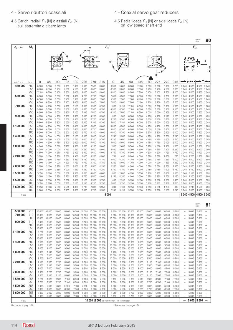
114 SR13 Edition February 2013
4 - Servo riduttori coassiali 4 - Coaxial servo gear reducers
4.5 Carichi radiali Fr2 [N] o assiali Fa2 [N] sull'estremità d'albero lento
4.5 Radial loads Fr2 [N] or axial loads Fa2 [N] on low speed shaft end
grand. size 80 n2 · Lh M2 Fr2
1) Fa21)
min-1 · h N m 0 45 90 135 180 225 270 315 0 45 90 135 180 225 270 315 450 000 500 6 300 5 600 6 000 7 100 5 000 5 000 7 500 8 000 3 550 5 600 8 000 7 100 6 300 6 300 6 000 3 750 2 240 4 500 4 500 2 240 355 6 700 6 300 6 700 7 500 7 100 7 500 8 000 8 000 6 300 8 000 8 000 7 500 6 700 6 700 7 500 6 300 2 240 4 500 4 500 2 240 250 7 100 6 700 7 100 7 500 8 000 8 000 8 000 8 000 8 000 8 000 8 000 7 500 7 100 7 100 7 500 8 000 2 240 4 500 4 500 2 240
560 000 500 6 000 5 300 5 300 6 000 4 000 4 250 6 700 7 500 2 650 4 500 7 500 6 300 5 600 6 000 4 750 2 800 2 240 4 500 4 500 1 700 355 6 300 5 600 6 000 6 700 6 300 6 300 8 000 7 500 5 300 7 500 7 500 6 700 6 300 6 300 6 700 5 600 2 240 4 500 4 500 2 240 250 6 700 6 300 6 300 7 100 8 000 8 000 8 000 7 500 7 500 8 000 7 500 7 100 6 700 6 700 7 100 7 500 2 240 4 500 4 500 2 240
710 000 500 5 300 4 750 5 000 4 750 3 150 3 350 5 300 6 700 1 800 3 150 7 100 6 000 5 300 5 300 3 350 1 800 2 240 4 500 4 500 1 000 355 5 600 5 300 5 300 6 300 5 600 5 600 7 500 6 700 4 500 6 300 7 100 6 300 5 600 5 600 6 300 4 500 2 240 4 500 4 500 2 240 250 6 000 5 600 6 000 6 300 7 100 7 100 7 500 6 700 6 300 7 500 7 100 6 300 6 000 6 000 6 300 6 300 2 240 4 500 4 500 2 240
900 000 500 4 750 4 000 4 250 3 750 2 360 2 500 4 250 6 300 1 000 1 900 6 700 5 300 4 750 4 750 2 120 1 060 2 240 4 500 4 500 400 355 5 300 4 750 5 000 5 600 4 500 4 750 6 700 6 300 3 750 5 300 6 700 5 600 5 300 5 300 5 600 3 750 2 240 4 500 4 500 2 240 250 5 600 5 300 5 300 6 000 6 300 6 300 7 100 6 300 5 600 7 100 6 300 6 000 5 600 5 600 6 000 5 600 2 240 4 500 4 500 2 240
1 120 000 355 4 750 4 250 4 500 5 300 4 000 4 000 6 000 6 000 3 000 4 500 6 000 5 300 4 750 4 750 4 750 3 000 2 240 4 500 4 500 1 700 250 5 000 4 750 5 000 5 600 5 600 5 600 6 700 6 000 5 000 6 300 6 000 5 300 5 000 5 000 5 600 5 000 2 240 4 500 4 500 2 240 180 5 300 5 000 5 000 5 600 6 300 6 700 6 300 6 000 6 000 6 300 6 000 5 600 5 300 5 300 5 600 6 000 2 240 4 500 4 500 2 240
1 400 000 355 4 250 4 000 4 000 4 750 3 150 3 350 5 000 5 300 2 240 3 550 5 600 4 750 4 250 4 250 3 750 2 240 2 240 4 500 4 500 1 180 250 4 750 4 250 4 500 5 000 4 750 5 000 6 300 5 300 4 250 5 600 5 600 5 000 4 750 4 750 5 000 4 250 2 240 4 500 4 500 2 240 180 5 000 4 500 4 750 5 300 5 600 6 000 6 000 5 300 5 600 6 000 5 600 5 000 4 750 4 750 5 000 5 600 2 240 4 500 4 500 2 240
1 800 000 355 4 000 3 350 3 550 3 750 2 500 2 650 4 250 5 000 1 500 2 650 5 300 4 500 3 750 4 000 2 800 1 600 2 240 4 000 4 500 670 250 4 250 4 000 4 000 4 750 4 250 4 250 5 600 5 000 3 550 5 000 5 300 4 500 4 250 4 250 4 500 3 550 2 240 4 500 4 500 2 000 180 4 500 4 250 4 250 4 750 5 300 5 300 5 600 5 000 4 750 5 300 5 000 4 750 4 500 4 500 4 750 4 750 2 240 4 500 4 500 2 240
2 240 000 355 3 550 3 150 3 350 3 000 1 900 2 000 3 350 4 500 750 1 400 5 000 4 000 3 550 3 550 1 600 750 2 240 3 750 4 500 280 250 2 800 3 550 3 750 4 250 3 550 3 750 5 000 4 750 3 000 4 250 4 750 4 250 3 750 3 750 4 250 3 000 2 240 4 000 4 500 1 500 180 4 000 3 750 4 000 4 500 4 750 4 750 5 300 4 750 4 250 5 000 4 750 4 250 4 000 4 000 4 250 4 250 2 240 4 250 4 500 2 240
2 800 000 250 3 550 3 150 3 350 4 000 3 000 3 150 4 500 4 250 2 360 3 550 4 500 4 000 3 550 3 550 3 750 2 360 2 240 3 550 4 500 1 180 180 3 750 3 550 3 550 4 000 4 250 4 250 4 750 4 250 3 750 4 750 4 500 4 000 3 750 3 750 4 000 3 750 2 240 3 750 4 500 2 000
3 550 000 250 3 150 2 800 3 000 3 500 2 500 2 650 4 000 4 000 1 800 2 800 4 250 3 550 3 150 3 150 3 000 1 900 2 240 3 150 4 500 800 180 3 350 3 150 3 350 3 750 3 550 3 750 4 500 4 000 3 150 4 250 4 000 3 750 3 350 3 350 3 750 3 150 2 240 3 350 4 500 1 600
4 500 000 250 3 000 2 650 2 650 3 000 2 000 2 120 3 350 3 750 1 400 2 240 3 750 3 150 2 800 2 800 2 500 1 400 2 240 3 000 4 500 500 180 3 150 2 800 3 000 3 350 3 150 3 150 4 250 3 750 2 650 3 750 3 750 3 350 3 150 3 150 3 350 2 650 2 240 3 000 4 500 1 320
5 600 000 250 2 650 2 360 2 500 2 500 1 600 1 700 2 800 3 350 630 1 180 3 550 3 000 2 650 2 650 1 250 630 2 240 2 240 4 500 200 180 2 800 2 650 2 800 3 150 2 650 2 800 3 750 3 350 2 240 3 150 3 550 3 150 2 800 2 800 3 150 2 240 2 240 2 800 4 500 1 000
max 8 000 2 240 4 500 4 500 2 240
Ved. note a pag. 104. See notes on page 104.
grand. size 81 560 000 710 10 000 10 000 10 000 10 000 10 000 10 000 10 000 10 000 9 500 10 000 10 000 10 000 10 000 10 000 10 000 9 500 – 5 600 5 600 –00
710 000 710 10 000 9 000 9 500 10 000 10 000 10 000 10 000 10 000 8 000 10 000 10 000 10 000 10 000 10 000 10 000 8 000 – 5 600 5 600 –00 500 10 000 10 000 10 000 10 000 10 000 10 000 10 000 10 000 10 000 10 000 10 000 10 000 10 000 10 000 10 000 10 000 – 5 600 5 600 –00
900 000 710 9 000 8 500 8 500 10 000 9 500 9 500 10 000 10 000 6 000 9 000 10 000 10 000 9 000 9 000 10 000 6 300 – 5 600 5 600 –00 500 10 000 9 000 9 500 10 000 10 000 10 000 10 000 10 000 10 000 10 000 10 000 10 000 10 000 10 000 10 000 10 000 – 5 600 5 600 –00 355 10 000 9 000 9 500 10 000 10 000 10 000 10 000 10 000 10 000 10 000 10 000 10 000 10 000 10 000 10 000 10 000 – 5 600 5 600 –00
1 120 000 500 9 000 8 500 9 000 10 000 10 000 10 000 10 000 10 000 10 000 10 000 10 000 10 000 9 000 9 000 10 000 10 000 – 5 600 5 600 –00 355 9 500 9 000 9 500 10 000 10 000 10 000 10 000 10 000 10 000 10 000 10 000 10 000 9 500 9 500 10 000 10 000 – 5 600 5 600 –00 250 10 000 9 500 9 500 10 000 10 000 10 000 10 000 10 000 10 000 10 000 10 000 10 000 10 000 10 000 10 000 10 000 – 5 600 5 600 –00
1 400 000 500 8 500 8 000 8 000 9 500 10 000 10 000 10 000 10 000 9 000 10 000 10 000 9 000 8 500 8 500 9 000 9 000 – 5 600 5 600 –00 355 9 000 8 500 8 500 9 500 10 000 10 000 10 000 10 000 10 000 10 000 10 000 9 500 9 000 9 000 9 500 10 000 – 5 600 5 600 –00 250 9 000 9 000 9 000 9 500 10 000 10 000 10 000 10 000 10 000 10 000 10 000 9 500 9 000 9 000 9 500 10 000 – 5 600 5 600 –00
1 800 000 500 8 000 7 100 7 500 8 500 9 000 9 000 10 000 9 500 6 700 9 500 9 500 8 500 7 500 7 500 8 500 6 700 – 5 600 5 600 –00 355 8 000 7 500 8 000 9 000 10 000 10 000 10 000 9 500 10 000 10 000 9 500 8 500 8 000 8 000 8 500 9 500 – 5 600 5 600 –00 250 8 500 8 000 8 500 9 000 10 000 10 000 10 000 9 500 10 000 10 000 9 500 9 000 8 500 8 500 9 000 9 500 – 5 600 5 600 –00
2 240 000 500 7 100 6 300 6 700 8 000 8 000 8 000 10 000 8 500 5 600 8 000 9 000 8 000 7 100 7 100 8 000 5 600 – 5 600 5 600 –00 355 7 500 7 100 7 500 8 000 9 500 10 000 10 000 8 500 9 000 9 500 9 000 8 000 7 500 7 500 8 000 9 000 – 5 600 5 600 –00 250 8 000 7 500 7 500 8 500 9 000 9 500 9 500 8 500 9 500 9 500 9 000 8 000 8 000 8 000 8 500 9 000 – 5 600 5 600 –00
2 800 000 355 7 100 6 700 6 700 7 500 9 000 9 000 9 000 8 000 8 000 9 000 8 500 7 500 7 100 7 100 7 500 8 500 – 5 600 5 600 –00 250 7 500 7 100 7 100 8 000 8 500 9 000 9 000 8 000 9 000 9 000 8 500 7 500 7 100 7 500 7 500 8 500 – 5 600 5 600 –00
3 550 000 355 6 300 6 000 6 300 7 100 8 000 8 000 8 500 7 500 7 100 8 500 8 000 7 100 6 300 6 300 7 100 7 100 – 5 600 5 600 –00 250 6 700 6 300 6 700 7 100 8 000 8 500 8 500 7 500 8 500 8 000 7 500 7 100 6 700 6 700 7 100 8 000 – 5 600 5 600 –00
4 500 000 355 6 000 5 600 5 600 6 700 7 100 7 100 8 000 7 100 6 300 8 000 7 100 6 300 6 000 6 000 6 700 6 300 – 5 600 5 600 –00 250 6 300 6 000 6 000 6 700 7 500 8 000 8 000 7 100 7 500 7 500 7 100 6 700 6 700 6 300 6 700 7 100 – 5 600 5 600 –00
5 600 000 355 5 600 5 000 5 300 6 000 6 300 6 300 7 500 6 700 4 750 6 700 6 700 6 000 5 300 5 600 6 000 5 000 – 5 600 5 600 –00 250 6 000 5 600 5 600 6 300 7 100 7 500 7 500 6 700 7 100 7 100 6 700 6 300 5 600 5 600 6 300 6 700 – 5 600 5 600 –00
max 10 000 (8 000 per «piedi corti» - for «short feet») – 5 600 5 600 –00
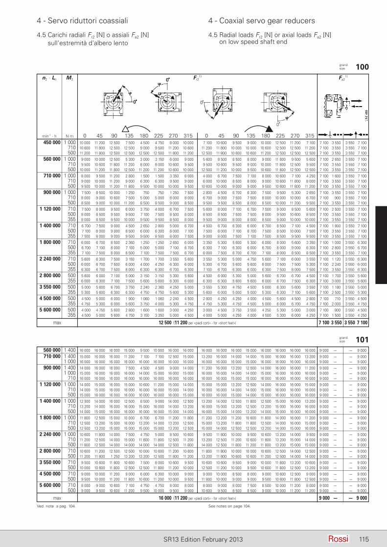
115SR13 Edition February 2013
4 - Servo riduttori coassiali 4 - Coaxial servo gear reducers
4.5 Carichi radiali Fr2 [N] o assiali Fa2 [N] sull'estremità d'albero lento
4.5 Radial loads Fr2 [N] or axial loads Fa2 [N] on low speed shaft end
grand. size 100 n2 · Lh M2 Fr2
1) Fa21)
min-1 · h N m 0 45 90 135 180 225 270 315 0 45 90 135 180 225 270 315 450 000 1 000 10 000 11 200 12 500 7 500 4 500 4 750 8 000 10 000 7 100 10 600 9 500 9 000 10 000 12 500 11 200 7 100 7 100 3 550 3 550 7 100 710 10 600 11 800 12 500 12 500 9 000 9 500 11 200 10 600 11 200 11 800 10 000 10 000 10 600 12 500 12 500 11 200 7 100 3 550 3 550 7 100 500 11 200 11 800 12 500 12 500 12 500 12 500 11 800 11 200 12 500 11 800 10 600 10 600 11 200 12 500 12 500 12 500 7 100 3 550 3 550 7 100
560 000 1 000 9 000 10 000 12 500 5 300 3 000 3 150 6 000 9 000 5 600 8 500 8 500 8 000 9 000 11 800 9 500 5 600 7 100 2 650 3 550 7 100 710 9 500 10 600 11 800 11 200 8 000 8 000 10 600 9 500 9 500 10 600 9 500 9 000 10 000 11 800 12 500 9 500 7 100 3 550 3 550 7 100 500 10 000 11 200 11 800 12 500 11 200 11 200 10 600 10 000 12 500 11 200 10 000 9 500 10 600 11 800 12 500 12 500 7 100 3 550 3 550 7 100
710 000 1 000 8 000 9 500 11 200 2 800 1 500 1 500 3 350 8 000 4 000 6 700 7 500 7 100 8 000 10 600 7 100 4 250 7 100 1 600 3 550 7 100 710 9 000 10 000 11 200 9 000 6 300 6 300 9 500 9 000 8 000 10 000 8 500 8 000 9 000 10 600 11 800 8 000 7 100 3 550 3 550 7 100 500 9 500 10 000 11 200 11 800 9 500 10 000 10 000 9 500 10 600 10 000 9 000 9 000 9 500 10 600 11 800 11 200 7 100 3 550 3 550 7 100
900 000 1 000 7 500 8 500 10 000 1 250 750 750 1 250 7 500 2 800 4 500 6 700 6 300 7 500 9 500 5 300 2 650 7 100 3 550 3 550 7 100 710 8 000 9 000 10 600 7 500 5 000 5 000 8 000 8 000 6 700 9 000 7 500 7 500 8 000 10 000 10 000 6 700 7 100 900 3 550 7 100 500 8 500 9 000 10 000 11 200 8 500 8 500 9 000 8 500 9 500 9 500 8 500 8 000 8 500 10 000 11 200 9 500 7 100 3 550 3 550 7 100
1 120 000 710 7 500 8 000 9 500 6 000 3 750 4 000 6 700 7 500 5 600 8 000 7 100 6 700 7 500 9 000 8 500 5 600 7 100 2 500 3 550 7 100 500 8 000 8 500 9 500 9 500 7 100 7 500 8 500 8 000 8 500 8 500 7 500 7 500 8 000 9 500 10 600 8 500 7 100 3 550 3 550 7 100 355 8 000 8 500 9 500 10 000 9 500 9 500 8 500 8 000 9 500 9 000 8 000 8 000 8 500 9 000 10 000 10 000 7 100 3 550 3 550 7 100
1 400 000 710 6 700 7 500 9 000 4 500 2 650 2 800 5 000 6 700 4 500 6 700 6 300 6 000 6 700 8 500 7 100 4 500 7 100 1 800 3 550 7 100 500 7 100 8 000 9 000 8 500 6 000 6 300 8 000 7 100 7 500 8 000 7 100 6 700 7 500 8 500 10 000 7 500 7 100 3 550 3 550 7 100 355 7 500 8 000 9 000 9 500 9 500 8 500 8 000 7 500 9 000 8 000 7 500 7 100 7 500 8 500 9 500 9 500 7 100 3 550 3 550 7 100
1 800 000 710 6 000 6 700 8 500 2 360 1 250 1 250 2 650 6 000 3 350 5 300 5 600 5 300 6 000 8 000 5 600 3 350 7 100 1 000 3 550 6 300 500 6 700 7 100 8 000 7 100 5 000 5 000 7 100 6 700 6 300 7 100 6 300 6 000 6 700 8 000 9 000 6 300 7 100 2 800 3 550 6 700 355 7 100 7 500 8 000 8 500 7 100 7 500 7 500 6 700 8 000 7 500 6 700 6 700 7 100 8 000 8 500 8 500 7 100 3 550 3 550 7 100
2 240 000 710 5 600 6 300 7 500 3 150 1 700 1 700 3 550 5 600 3 550 5 300 5 000 4 750 5 600 7 100 6 000 3 550 7 100 1 120 3 550 6 300 500 6 000 6 700 7 500 6 000 4 000 4 250 6 300 6 000 5 300 6 700 5 600 5 600 6 000 7 500 7 500 5 300 7 100 2 240 3 550 6 000 355 6 300 6 700 7 500 8 000 6 300 6 300 6 700 6 300 7 100 6 700 6 300 6 000 6 300 7 500 8 000 7 500 7 100 3 550 3 550 6 300
2 800 000 500 5 600 6 000 7 100 5 000 3 150 3 150 5 300 5 600 4 500 6 000 5 300 5 000 5 600 6 700 6 700 4 500 7 100 1 700 3 550 5 600 355 6 000 6 300 7 100 7 500 5 600 5 600 6 300 6 000 6 300 6 300 5 600 5 600 6 000 6 700 7 500 6 300 7 100 3 000 3 550 5 600
3 550 000 500 5 000 5 600 6 700 3 750 2 240 2 360 4 250 5 000 3 550 5 300 4 750 4 500 5 000 6 300 5 600 3 550 7 100 1 180 3 550 5 000 355 5 300 5 600 6 300 6 300 4 750 4 750 5 600 5 300 5 600 6 000 5 000 5 000 5 300 6 300 7 100 5 600 7 100 2 500 3 550 5 300
4 500 000 500 4 500 5 000 6 000 1 900 1 060 1 060 2 240 4 500 2 800 4 250 4 250 4 000 4 500 5 600 4 500 2 800 7 100 710 3 550 4 500 355 4 750 5 300 6 000 5 600 3 750 4 000 5 300 4 750 4 750 5 300 4 750 4 500 5 000 6 000 6 700 4 750 7 100 2 000 3 550 4 750
5 600 000 500 4 000 4 750 5 600 2 800 1 600 1 600 3 000 4 250 3 000 4 500 3 750 3 550 4 250 5 300 5 000 3 000 7 100 800 3 550 4 500 355 4 500 5 000 5 600 4 750 3 150 3 350 5 000 4 500 4 000 5 000 4 250 4 000 4 500 5 300 6 000 4 250 7 100 1 500 3 550 4 250
max 12 500 (11 200 per «piedi corti» - for «short feet») 7 100 3 550 3 550 7 100
Ved. note a pag. 104. See notes on page 104.
grand. size 101 560 000 1 400 16 000 16 000 16 000 15 000 9 500 10 000 16 000 16 000 16 000 16 000 16 000 15 000 16 000 16 000 16 000 16 000 9 000 –00 – 9 000
710 000 1 400 15 000 16 000 16 000 11 200 7 100 7 100 12 500 15 000 13 200 16 000 14 000 14 000 15 000 16 000 16 000 13 200 9 000 –00 – 9 000 1 000 16 000 16 000 16 000 16 000 16 000 16 000 16 000 16 000 16 000 16 000 16 000 15 000 16 000 16 000 16 000 16 000 9 000 –00 – 9 000
900 000 1 400 14 000 16 000 16 000 7 500 4 500 4 500 9 000 14 000 11 200 16 000 13 200 12 500 14 000 16 000 16 000 11 200 9 000 –00 – 9 000 1 000 15 000 16 000 16 000 16 000 14 000 15 000 16 000 15 000 16 000 16 000 14 000 14 000 15 000 16 000 16 000 16 000 9 000 –00 – 9 000 710 16 000 16 000 16 000 16 000 16 000 16 000 16 000 16 000 16 000 16 000 15 000 15 000 16 000 16 000 16 000 16 000 9 000 –00 – 9 000
1 120 000 1 000 14 000 15 000 16 000 15 000 10 600 11 200 15 000 14 000 15 000 15 000 13 200 12 500 14 000 16 000 16 000 15 000 9 000 –00 – 9 000 710 14 000 15 000 16 000 16 000 16 000 16 000 15 000 14 000 16 000 16 000 14 000 14 000 15 000 16 000 16 000 16 000 9 000 –00 – 9 000 500 15 000 16 000 16 000 16 000 16 000 16 000 16 000 15 000 16 000 16 000 15 000 14 000 15 000 16 000 16 000 16 000 9 000 –00 – 9 000
1 400 000 1 000 12 500 14 000 16 000 12 500 8 500 9 000 14 000 12 500 13 200 14 000 12 500 11 800 12 500 15 000 16 000 13 200 9 000 –00 – 9 000 710 13 200 14 000 16 000 16 000 15 000 16 000 14 000 13 200 16 000 15 000 13 200 12 500 13 200 15 000 16 000 16 000 9 000 –00 – 9 000 500 14 000 15 000 16 000 16 000 16 000 16 000 15 000 14 000 16 000 15 000 14 000 13 200 14 000 15 000 16 000 16 000 9 000 –00 – 9 000
1 800 000 1 000 11 800 12 500 15 000 10 000 6 700 6 700 11 200 11 800 11 200 13 200 11 200 10 600 11 800 14 000 16 000 11 200 9 000 –00 – 9 000 710 12 500 13 200 15 000 16 000 13 200 14 000 13 200 12 500 15 000 13 200 11 800 11 800 12 500 14 000 16 000 15 000 9 000 –00 – 9 000 500 12 500 13 200 15 000 15 000 15 000 15 000 13 200 12 500 15 000 14 000 12 500 12 500 13 200 14 000 15 000 16 000 9 000 –00 – 9 000
2 240 000 1 000 10 600 11 800 14 000 7 500 4 750 5 000 8 500 10 600 9 500 11 800 10 000 9 500 10 600 13 200 14 000 9 500 9 000 –00 – 9 000 710 11 200 12 500 14 000 15 000 11 800 11 800 12 500 11 200 13 200 12 500 11 200 10 600 11 800 13 200 15 000 14 000 9 000 –00 – 9 000 500 11 800 12 500 14 000 14 000 14 000 14 000 12 500 11 800 14 000 12 500 11 800 11 200 11 800 13 200 15 000 15 000 9 000 –00 – 9 000
2 800 000 710 10 600 11 200 12 500 12 500 10 000 10 600 11 200 10 600 11 800 11 800 10 000 10 000 10 600 12 500 14 000 12 500 9 000 –00 – 9 000 500 11 200 11 800 1 250 13 200 13 200 12 500 11 800 11 200 13 200 11 800 10 600 10 600 11 200 12 500 14 000 14 000 9 000 –00 – 9 000
3 550 000 710 9 500 10 600 11 800 10 600 7 500 8 000 10 600 9 500 10 600 10 600 9 500 9 000 10 000 11 800 13 200 10 600 9 000 –00 – 9 000 500 10 000 10 600 11 800 12 500 12 500 11 800 11 200 10 000 12 500 11 200 10 000 9 500 10 600 11 800 12 500 13 200 9 000 –00 – 9 000
4 500 000 710 9 000 10 000 11 200 9 000 6 000 6 300 10 000 9 000 9 000 10 000 8 500 8 000 9 000 10 600 12 500 9 000 9 000 –00 – 9 000 500 9 500 10 000 11 200 11 800 10 600 11 200 10 000 9 500 11 800 10 000 9 000 9 000 9 500 10 600 11 800 12 500 9 000 –00 – 9 000
5 600 000 710 8 000 9 000 10 600 7 100 4 750 4 750 8 000 8 000 8 000 9 000 8 000 7 500 8 500 10 000 11 200 8 000 9 000 –00 – 9 000 500 9 000 9 500 10 600 11 200 9 500 10 000 9 500 9 000 10 600 9 500 8 500 8 500 9 000 10 000 11 200 11 200 9 000 –00 – 9 000
max 16 000 (11 200 per «piedi corti» - for «short feet») 9 000 –00 – 9 000
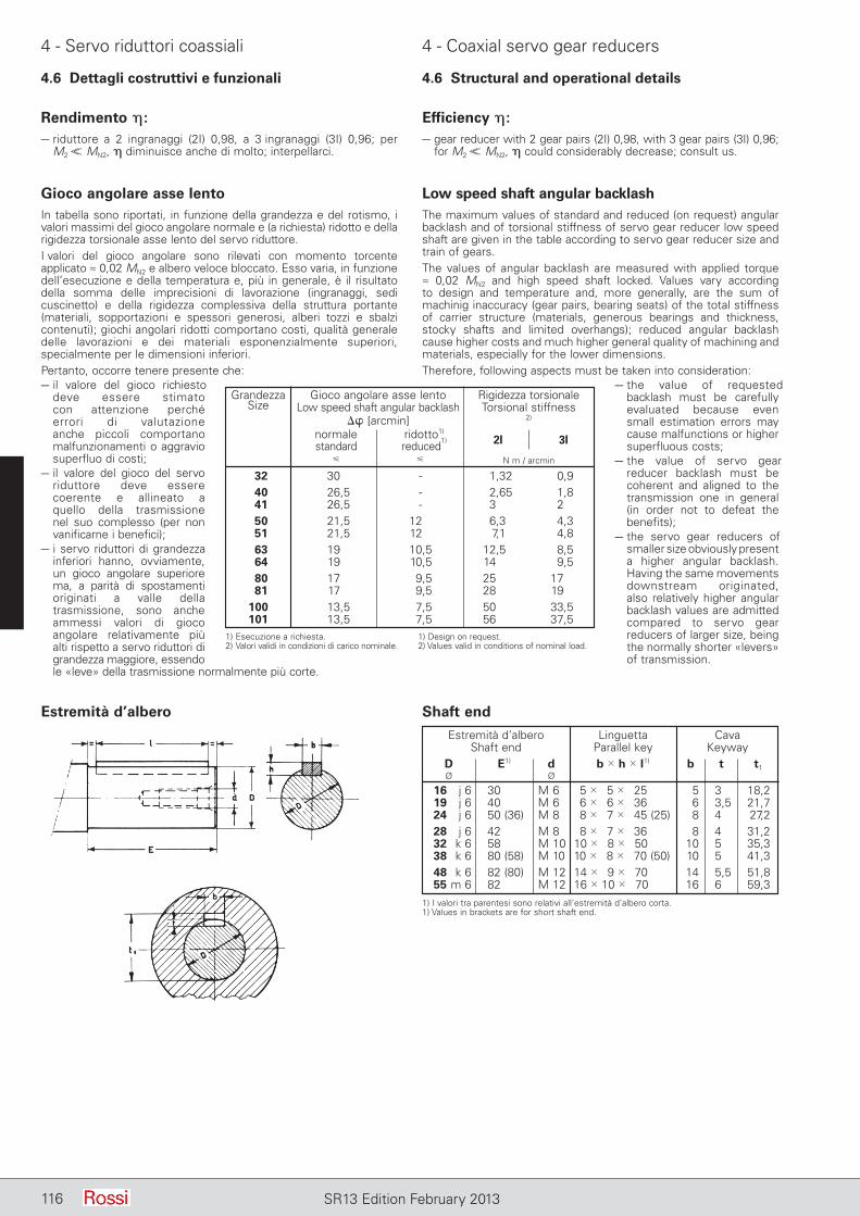
116 SR13 Edition February 2013
4 - Servo riduttori coassiali 4 - Coaxial servo gear reducers
4.6 Dettagli costruttivi e funzionali 4.6 Structural and operational details
Gioco angolare asse lentoIn tabella sono riportati, in funzione della grandezza e del rotismo, i valori massimi del gioco angolare normale e (a richiesta) ridotto e della rigidezza torsionale asse lento del servo riduttore.I valori del gioco angolare sono rilevati con momento torcente applicato ≈ 0,02 MN2 e albero veloce bloccato. Esso varia, in funzione dell’esecuzione e della temperatura e, più in generale, è il risultato della somma delle imprecisioni di lavorazione (ingranaggi, sedi cuscinetto) e della rigidezza complessiva della struttura portante (materiali, sopportazioni e spessori generosi, alberi tozzi e sbalzi contenuti); giochi angolari ridotti comportano costi, qualità generale delle lavorazioni e dei materiali esponenzialmente superiori, specialmente per le dimensioni inferiori. Pertanto, occorre tenere presente che:– il valore del gioco richiesto
deve es sere stimato con at tenzione perché errori di va lutazione anche piccoli comportano malfunzionamenti o ag gravio superfluo di costi;
– il valore del gioco del servo riduttore deve essere coerente e al lineato a quello della trasmissione nel suo complesso (per non vanificarne i benefici);
– i servo riduttori di grandezza inferiori han no, ovviamente, un gioco angolare superiore ma, a parità di spostamenti originati a valle della trasmissione, sono anche ammessi valori di gioco angolare relativamente più alti rispetto a servo riduttori di grandezza maggiore, essendo le «leve» della trasmissione normalmente più corte.
Low speed shaft angular bac k lashThe maximum values of standard and reduced (on request) angular backlash and of torsional stiffness of servo gear reducer low speed shaft are given in the table according to servo gear reducer size and train of gears.The values of angular backlash are measured with applied torque ≈ 0,02 MN2 and high speed shaft locked. Values vary according to design and temperature and, more generally, are the sum of machinig inaccuracy (gear pairs, bearing seats) of the total stiffness of carrier structure (materials, generous bearings and thickness, stocky shafts and limited overhangs); reduced angular backlash cause higher costs and much higher general quality of machining and materials, especially for the lower dimensions.Therefore, following aspects must be taken into consideration:
– the value of requested backlash must be carefully evaluated because even small estimation errors may cause malfunctions or higher superfluous costs;
– the value of servo gear reducer backlash must be coherent and aligned to the transmission one in general (in order not to defeat the benefits);
– the servo gear reducers of smaller size obviously present a higher angular backlash. Having the same movements downstream originated, also relatively higher angular backlash values are admitted compared to servo gear reducers of larger size, being the normally shorter «levers» of transmission.
Estremità d’albero Shaft end
Estremità d’albero Linguetta Cava Shaft end Parallel key Keyway D E1) d b 3 h 3 l1) b t t1 Ø Ø
16 j 6 30 M 6 5 3 5 3 25 5 3 18,2 19 j 6 40 M 6 6 3 6 3 36 6 3,5 21,7 24 j 6 50 (36) M 8 8 3 7 3 45 (25) 8 4 27,2 28 j 6 42 M 8 8 3 7 3 36 8 4 31,2 32 k 6 58 M 10 10 3 8 3 50 10 5 35,3 38 k 6 80 (58) M 10 10 3 8 3 70 (50) 10 5 41,3 48 k 6 82 (80) M 12 14 3 9 3 70 14 5,5 51,8 55 m 6 82 M 12 16 3 10 3 70 16 6 59,3
Rendimento h:– riduttore a 2 ingranaggi (2I) 0,98, a 3 ingranaggi (3I) 0,96; per
M2 ,, MN2, h diminuisce anche di molto; interpellarci.
Efficiency h:– gear reducer with 2 gear pairs (2I) 0,98, with 3 gear pairs (3I) 0,96;
for M2 ,, MN2, h could considerably decrease; consult us.
Grandezza Gioco angolare asse lento Rigidezza torsionale Size Low speed shaft angular backlash Torsional stiffness D [arcmin] 2)
normale ridotto1) 2I 3I standard reduced1)
¯ ¯ N m / arcmin
32 30 - 1,32 0,9 40 26,5 - 2,65 1,8 41 26,5 - 3 2 50 21,5 12 6,3 4,3 51 21,5 12 7,1 4,8 63 19 10,5 12,5 8,5 64 19 10,5 14 9,5 80 17 9,5 25 17 81 17 9,5 28 19 100 13,5 7,5 50 33,5 101 13,5 7,5 56 37,51) Esecuzione a richiesta.2) Valori validi in condizioni di carico nominale.
1) Design on request.2) Values valid in conditions of nominal load.
1) I valori tra parentesi sono relativi all’estremità d’albero corta.1) Values in brackets are for short shaft end.
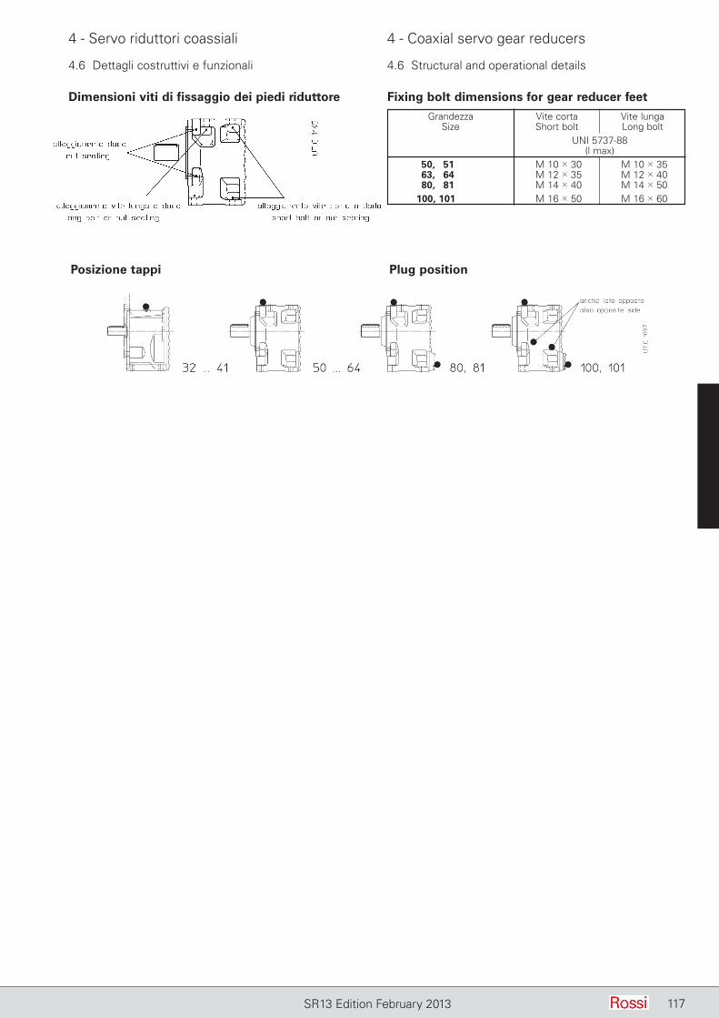
117SR13 Edition February 2013
4 - Servo riduttori coassiali 4 - Coaxial servo gear reducers
4.6 Dettagli costruttivi e funzionali 4.6 Structural and operational details
Posizione tappi Plug position
Dimensioni viti di fissaggio dei piedi riduttore Fixing bolt dimensions for gear reducer feet
Grandezza Vite corta Vite lunga Size Short bolt Long bolt Gear reducer size UNI 5737-88 size (l max) 50, 51 M 10 3 30 M 10 3 35 63, 64 M 12 3 35 M 12 3 40 80, 81 M 14 3 40 M 14 3 50 100, 101 M 16 3 50 M 16 3 60

118 SR13 Edition February 2013
4 - Servo riduttori coassiali 4 - Coaxial servo gear reducers
118 SR13 Edition January 2013
Estremità d’albero lento spostata in avanti (gr. 40)I servo riduttori grandezza 40 con flangia possono essere forniti con estremità d’albero lento spostata in avanti e sopportazione rin-forzata (i valori dei carichi radiali sono quelli indicati per la grand. 41, ved. cap. 4.5). Questa esecuzione è di serie per tutte le altre grandezze.
Descrizione aggiuntiva alla designazione per l’ordinazione: flangia B5 maggiorata.
Gioco ridottoTutti i servo riduttori, escluse le grand. 32 e 41, possono essere forniti con gioco angolare asse lento ridotto: valori indicati al cap. 4.6.Descrizione aggiuntiva alla designazione per l’ordinazione: gioco ridotto.
Varie– Anelli tenuta speciali; doppia tenuta asse lento (solo per grand. 80).
Supplementary description when ordering by designation: oversized B5 flange.
Reduced backlashAll servo gear reducers, excluding sizes 32 and 41, can be supplied with reduced low speed shaft angular backlash: values stated on ch. 4.6.Supplementary description when ordering by designation: reduced backlash.
Miscellaneous– Special seal rings, double seal on low speed shaft (only for sizes 80).
Descrizione aggiuntiva alla designazione per l’ordinazione: estremità d’albero lento spostata in avanti.
Flangia B5 maggiorata (asse lento)I servo riduttori grandezza 50 possono essere forniti con flangia B5 maggiorata (sempre con fori passanti) riportata sulla flangia B5 di serie. Il piano flangia coincide in questo caso con la battuta dell’estremità d’albero lento.Il servo riduttore deve essere fissato dopo aver fissato la flangia sulla macchina; per tale motivo l'accessorio viene fornito smontato.Si raccomanda l’impiego, sia nelle viti sia nei piani di unione, di adesivi bloccanti tipo LOCTITE.
Supplementary description when ordering by designation: low speed shaft end shifted forward.
Oversized B5 flange (low speed shaft)Servo gear reducers (size 50) can be supplied with oversized B5 flange (always having through holes) fitted on standard B5 flange. Flange plane coincides with low speed shaft end shoulder.The servo gear reducer is to be fastened after having fastened the flange on the machine; for this reason the accessory is to be supplied separately.Locking adhesives such as LOCTITE, should be used both on screws and coupling surfaces.
Grandezza F M N P Q S S1 Size Ø Ø Ø Ø h6 1)
50, 51 10,5 165 130 200 3,5 12 5,5 63, 64 13,0 215 180 250 4 14 6,5 80, 81 13,0 265 230 300 4 15 9 100, 101 17,0 300 250 350 5 17 10,51) Vite tipo UNI 5931-841) Screw type UNI 5931-84
Grandezza c G1 Size Ø
40 25 65Per il valore delle quote D, E e delle di men-sioni mancanti ved. cap. 4.4.For D, E and remaining dimensions see ch. 4.4.
Low speed shaft end shifted forward (size 40)The servo gear reducers size 40 with flange can be supplied with low speed shaft end shifted forward and with strengthened bearings (radial load values are those stated for the size 41, see ch. 4.5). This design is standard for all remaining sizes.
4.7 Accessori ed esecuzioni speciali 4.7 Accessories and non-standard designs
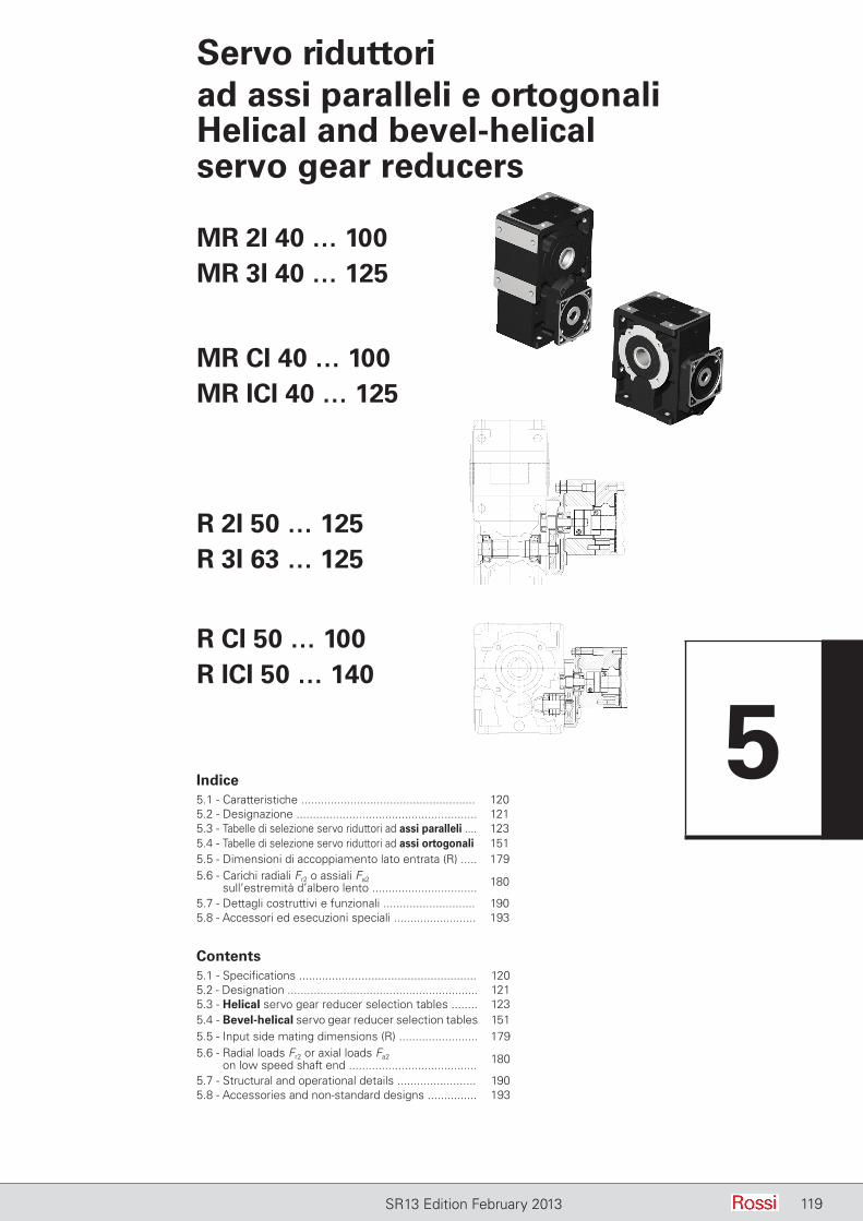
119SR13 Edition February 2013
Servo riduttori ad assi paralleli e ortogonaliHelical and bevel-helical servo gear reducers
Indice5.1 - Caratteristiche ..................................................... 1205.2 - Designazione ....................................................... 1215.3 - Tabelle di selezione servo riduttori ad assi paralleli .... 1235.4 - Tabelle di selezione servo riduttori ad assi ortogonali 1515.5 - Dimensioni di accoppiamento lato entrata (R) ..... 1795.6 - Carichi radiali Fr2 o assiali Fa2
sull’estremità d’albero lento ................................ 180
5.7 - Dettagli costruttivi e funzionali ............................ 1905.8 - Accessori ed esecuzioni speciali ......................... 193
MR 2I 40 … 100MR 3I 40 … 125
R CI 50 … 100R ICI 50 … 140
Contents5.1 - Specifications ...................................................... 1205.2 - Designation .......................................................... 1215.3 - Helical servo gear reducer selection tables ........ 1235.4 - Bevel-helical servo gear reducer selection tables 1515.5 - Input side mating dimensions (R) ........................ 1795.6 - Radial loads Fr2 or axial loads Fa2
on low speed shaft end ....................................... 180
5.7 - Structural and operational details ........................ 1905.8 - Accessories and non-standard designs ............... 193
MR CI 40 … 100MR ICI 40 … 125
R 2I 50 … 125R 3I 63 … 125
5
120 SR13 Edition February 2013
5 - Servo riduttori ad assi paralleli e ortogonali
5 - Helical and bevel-helical servo gear reducers
5.1 Caratteristiche
– due diversi tipi di servo riduttore: tipo MR per accoppiamento diretto con il servo motore (massima compattezza) e tipo R per accoppiamento con campana e giunto torsionalmente rigido (massima flessibilità di applicazione);
– 6 grandezze (di cui 2 doppie, per un totale di 8 grandezze: 40 … 125 (MR), 50 ... 140 (R));
– 2 classi di gioco angolare asse lento: gioco normale, gioco ridotto (a richiesta);
– calettamento servo motore: MR 2I, CI servo motore calettato direttamente mediante accoppiamento stretto con linguetta, intagli e collare di bloccaggio; MR 3I, ICI, servo motore con pignone prima riduzione calettato direttamente sull’estremità d’albero mediante interferenza e linguetta; R 2I, 3I, CI, ICI, servo motore calettato mediante giunto torsionalmente rigido e campana di adattamento;
– cuscinetti volventi a rulli conici, escluso alcuni casi in cui sono a rulli cilindrici o a sfere;
– possibilità di seconda sporgenza d'albero veloce ( o intermedio per rotismo 3I, ICI);
– albero lento cavo di acciaio, con cava linguetta e (grand. 64 ... 125) gole anello elastico per estrazione; albero lento normale (sporgente a destra o a sinistra) o bisporgente (ved. cap. 5.8);
– fissaggio universale: con piedi integrali alla carcassa su 4 facce (3 facce per CI, ICI) e con flangia B14 su due facce (1 faccia per 2I, 3I); flangia B5 con centraggio «foro» montabile sulle flange B14 (ved. capp. 5.7 e 5.8);
– anelli di tenuta per elevata velocità in entrata per tutte le grandezze;– lubrificazione a bagno d’olio; olio sintetico per lubrificazione «a
vita» e con 1 tappo (grandezze 40 ... 64) o 2 tappi (grandezze 80 e 81), fornite complete di olio; olio sintetico o minerale (ved. cap. 6.7) con tappo di carico con valvola, scarico e livello (grandezze 100, 125); tenuta stagna;
– verniciatura: protezione esterna con vernice sintetica nera RAL 9005 (opacità 5 glass), idonea a resistere ai normali ambienti industriali e a consentire ulteriori finiture con vernici sintetiche; protezione interna con vernice a polveri epossidiche (grand. 50 … 100) idonea a resistere agli oli sintetici o con vernice sintetica (grand. 125) idonea a resistere agli oli minerali o sintetici a base di polialfaolefine.
Rotismo:– a 2, 3 ingranaggi cilindrici (assi paralleli);– a 1 ingranaggio conico e 1, 2 cilindrici (assi ortogonali);– rapporti di trasmissione nominali secondo R10 (6,3 ... 63);– ingranaggi di acciaio 16 CrNi4 e 18 NiCrMo5 UNI 7846-78
cementati/temprati;– Ingranaggi cilindrici a dentatura elicoidale con profilo rettificato;– ingranaggi conici a dentatura spiroidale GLEASON con profilo
accuratamente rodato;– capacità di carico del rotismo calcolata a rottura e pitting.
5.1 Specifications
– two different gear reducer types: type MR for direct coupling with the servo motor (maximum compactness) and type R for coupling with bell and torsionally stiff coupling (wide range of mating dimensions);
– 6 sizes (with 2 size pairs, for a total of 8 sizes: 40 … 125 (MR), 50 ... 140 (R));
– 2 classes of low speed shaft angular backlash: standard backlash, reduced backlash (on request);
– servo motor coupling: MR 2I, CI, servo motor directly fitted with key, slots and hub clamp; MR 3I, ICI, servo motor with first reduction stage pinion directly fitted with interference and key onto the shaft end; R 2I, 3I, CI, ICI servo motor fitted through torsionally stiff coupling and bell housing;
– taper roller bearings, excluding some shafts on which bearings are cylindrical roller or ball type;
– possibility of second high speed shaft extension (or intermediate shaft extension for train of gears 3I, ICI);
– hollow low speed shaft in steel, with keyway and (for sizes 64 ... 125) circlip grooves for extraction; standard (left or right hand extension) or double extension low speed shaft (see h. 5.8);
– universal mounting having feet integral with housing on 4 faces (on 3 faces for train of gears CI, ICI) and with B14 flange on 2 faces (1 face for train of gears 2I, 3I); B5 flange with spigot «recess» mountable on faces with B14 flange (see ch. 5.7 and 5.8);
– seal rings for high input speed, available for all sizes;– oil bath lubrication: synthetic oil providing «long-life» lubrication:
with 1 (sizes 40 ... 64) or 2 plugs (sizes 80, 81), supplied filled with oil; synthetic or mineral oil (see ch. 6.7) with filler plug with valve, drain and level plugs (sizes 100, 125); sealed;
– paint: external coating with black synthetic paint RAL 9005 (opacity 5 glass) suitable to resist the normal industrial environment and to allow further finishing with synthetic paints; internal protection in epoxy powder paint (sizes 50 ... 100) properly resistant to synthetic oils, or with synthetic paint (sizes 125) providing resistance to mineral oils or to polyalphaolefines synthetic oils.
Train of gears:– 2, 3 cylindrical gear pairs (helical servo gear reducers);– 1 bevel gear pair plus 1, 2 cylindrical gear pairs (bevel-helical servo
gear reducers);– nominal transmission ratios to R10 series (6,3 ... 63);– casehardened and hardened gear pairs in 16 CrNi4 and
18NiCrMo5, according to UNI 7846-78;– helical toothed cylindrical gear pairs with ground profile;– GLEASON spiral bevel gear pairs with accurately lapped profile; – gears load capacity calculated for tooth breakage and pitting.
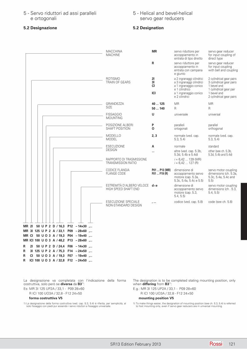
121SR13 Edition February 2013
MACCHINAMACHINE
MR servo riduttore per accoppiamento in entrata di tipo diretto
servo gear reducer for input coupling of direct type
R servo riduttore per accoppiamento in entrata con campana e giunto
servo gear reducer for input coupling with bell and coupling
ROTISMOTRAIN OF GEARS
2I3ICI
a 2 ingranaggi cilindricia 3 ingranaggi cilindricia 1 ingranaggio conico e 1 cilindrico
2 cylindrical gear pairs3 cylindrical gear pairs1 bevel and 1 cylindrical gear pair
ICI a 1 ingranaggio conico e 2 cilindrici
1 bevel and 2 cylindrical gear pairs
GRANDEZZASIZE
40 ... 12550 ... 140
MRR
MRR
FISSAGGIOMOUNTING
U universale universal
POSIZIONE ALBERISHAFT POSITION
PO
paralleliortogonali
parallelorthogonal
MODELLOMODEL
2, 3 normale (ved. cap. 5.3, 5.4)
normale (ved. cap. 5.3, 5.4)
ESECUZIONEDESIGN
A...
normalealtre (ved. cap. 5.3b, 5.3d, 5.4b e 5.4d)
standardother (see ch. 5.3b, 5.3d, 5.4b and 5.4d)
RAPPORTO DI TRASMISSIONETRANSMISSION RATIO
i = 6,42 ... 139 (MR)i = 6,42 ... 127 (R)
CODICE FLANGIAFLANGE CODE
P01 ... P13 (MR)F01 ... F19 (R)
dimensione di accoppiamento servo motore (cap. 5.3a, 5.3c, 5.4a, 5.4c e 5.5)
servo motor coupling dimensions (ch. 5.3a, 5.3c, 5.4a, 5.4c and 5.5)
ESTREMITÀ D'ALBERO VELOCEHIGH SPEED SHAFT END
d×e dimensione di accoppiamento servo motore (cap. 5.3, 5.4, 5.5)
servo motor coupling dimensions (ch. .5.3, 5.4, 5.5)
ESECUZIONE SPECIALE NON-STANDARD DESIGN
, ... codice (ved. cap. 5.8) code (see ch. 5.8)
MR 2I 50 U P 2 D / 16,3 P12 – 14×30 ,...MR 3I 125 U P 2 A / 33,1 P09 – 28×60 ,...MR CI 50 U O 3 A / 19,3 P04 – 19×40 ,...MR ICI 100 U O 3 A / 48,2 P13 – 28×60 ,...
R 2I 50 U P 2 D / 24,4 F06 – 14×30 ,...R 3I 125 U P 2 A / 75,3 F14 – 24×50 ,...R CI 50 U O 3 A / 19,3 F07 – 19×40 ,...R ICI 100 U O 3 A / 32,8 F12 – 24×50 ,...
La designazione va completata con l'indicazione della forma costruttiva, solo però se diversa da B31):Es: MR 3I 125 UP2A / 33,1 - P09 28×60 R ICI 100 UO3A / 32,8 - F12 24×50
forma costruttiva V5
1) La designazione della forma costruttiva (ved. cap. 5.3, 5.4) è riferita, per semplicità, al solo fissaggio con piedi pur essendo i servo riduttori a fissaggio universale.
The designation is to be completed stating mounting position, only when differing from B31):E.g.: MR 3I 125 UP2A / 33,1 - P09 28×60 R ICI 100 UO3A / 32,8 - F12 24×50
mounting position V5
1) To make things easier, the designation of mounting position (see ch. 5.3, 5.4) is referred to foot mounting only, even if servo gear reducers are in universal mounting.
5 - Servo riduttori ad assi paralleli e ortogonali
5 - Helical and bevel-helical servo gear reducers
5.2 Designazione 5.2 Designation
122 SR13 Edition January 2013
Pagina lasciata intenzionalmente biancaThis page is intentionally left blank
SR13 Edition February 2013122
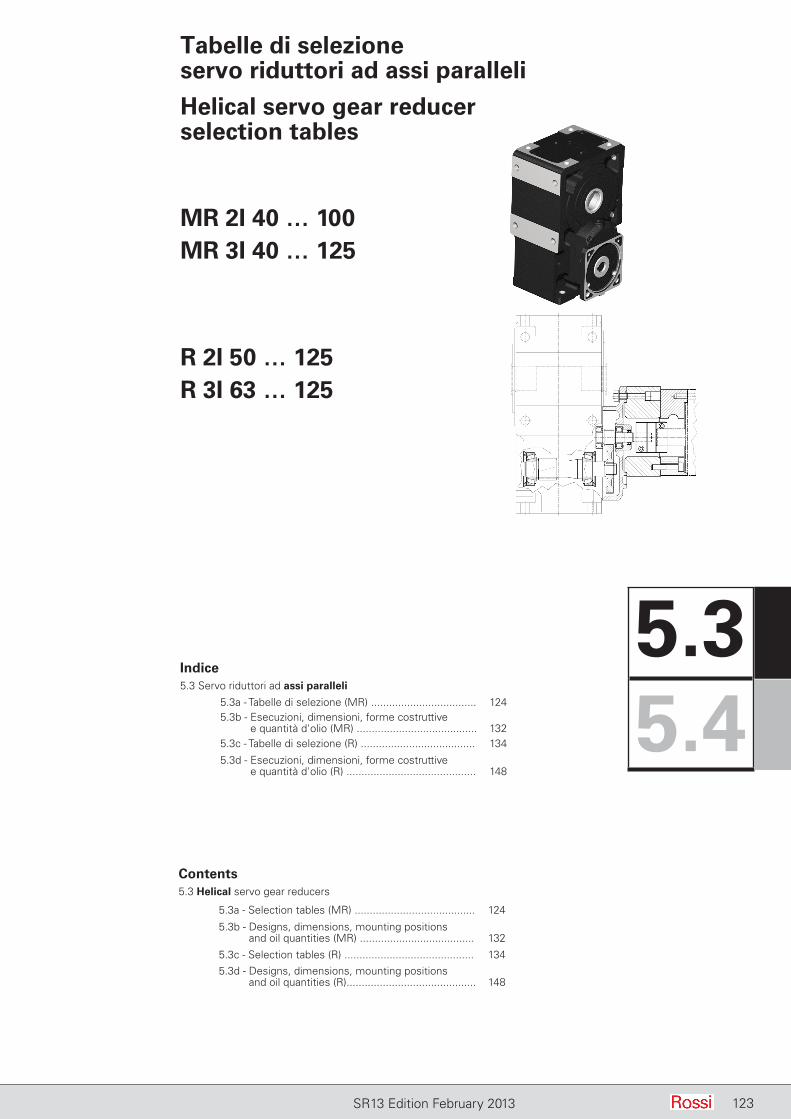
123SR13 Edition February 2013 123SR13 Edition February 2013
Tabelle di selezione servo riduttori ad assi paralleli
Helical servo gear reducer selection tables
Indice5.3 Servo riduttori ad assi paralleli
5.3a - Tabelle di selezione (MR) ................................... 1245.3b - Esecuzioni, dimensioni, forme costruttive
e quantità d'olio (MR) ........................................ 1325.3c - Tabelle di selezione (R) ...................................... 134
5.3d - Esecuzioni, dimensioni, forme costruttive e quantità d'olio (R) ........................................... 148
MR 2I 40 … 100MR 3I 40 … 125
R 2I 50 … 125R 3I 63 … 125
Contents5.3 Helical servo gear reducers
5.3a - Selection tables (MR) ........................................ 124
5.3b - Designs, dimensions, mounting positions and oil quantities (MR) ...................................... 132
5.3c - Selection tables (R) ........................................... 1345.3d - Designs, dimensions, mounting positions
and oil quantities (R)........................................... 148
5.35.4
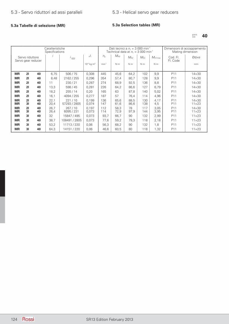
5.3 - Servo riduttori ad assi paralleli 5.3 - Helical servo gear reducers
124 SR13 Edition February 2013
5.3a Tabelle di selezione (MR) 5.3a Selection tables (MR)
CaratteristicheSpecifications
Dati tecnici a n1 = 3 000 min-1
Technical data at n1 = 3 000 min-1Dimensioni di accoppiamento
Mating dimension
Servo riduttoreServo gear reducer
i J1 n2 MN2 MA2 ME2 MA1max Cod. Fl.Fl. Code
Ød×e
10-4 kg m2 min-1 N m N m N m N m mm
MR 2I 40 6,75 506 / 75 0,308 445 45,6 64,2 102 9,9 P11 14×30MR 2I 40 8,48 2162 / 255 0,296 354 57,4 80,7 128 9,9 P11 14×30MR 2I 40 11 230 / 21 0,287 274 68,9 92,5 136 8,8 P11 14×30MR 2I 40 13,3 598 / 45 0,281 226 64,2 86,6 127 6,79 P11 14×30MR 2I 40 18,2 255 / 14 0,20 165 63,0 87,8 140 5,02 P11 14×30MR 2I 40 16,1 4094 / 255 0,277 187 57,0 76,4 114 4,96 P11 14×30MR 2I 40 22,1 221 / 10 0,199 136 65,6 88,5 130 4,17 P11 14×30MR 3I 40 20,4 57293 / 2805 0,074 147 61,6 86,6 138 4,5 P11 11×23MR 2I 40 26,7 267 / 10 0,197 112 58,3 78,0 117 3,05 P11 14×30MR 3I 40 26,4 6095 / 231 0,073 114 72,9 97,9 144 3,95 P11 11×23MR 3I 40 32 15847 / 495 0,073 93,7 66,7 90,0 132 2,99 P11 11×23MR 3I 40 38,7 108491 / 2805 0,073 77,6 59,2 79,3 118 2,18 P11 11×23MR 3I 40 53,2 11713 / 220 0,06 56,3 68,2 90,0 132 1,8 P11 11×23MR 3I 40 64,3 14151 / 220 0,06 46,6 60,5 80,0 118 1,32 P11 11×23
grand. size 40
i esattoexact
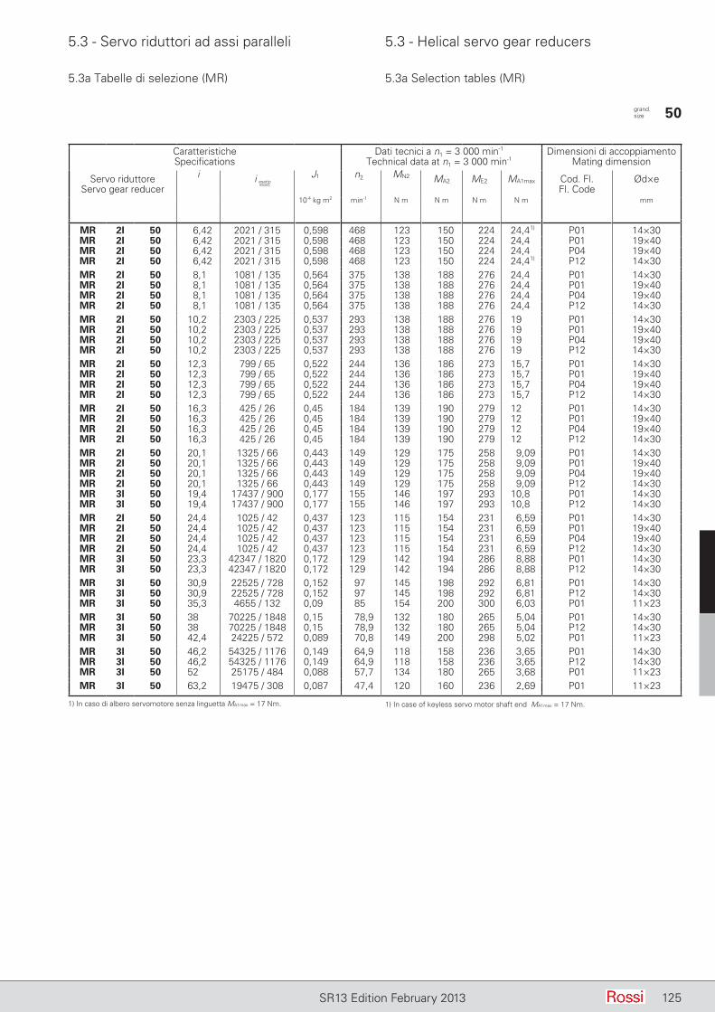
5.3 - Servo riduttori ad assi paralleli 5.3 - Helical servo gear reducers
125SR13 Edition February 2013
5.3a Tabelle di selezione (MR) 5.3a Selection tables (MR)
CaratteristicheSpecifications
Dati tecnici a n1 = 3 000 min-1
Technical data at n1 = 3 000 min-1Dimensioni di accoppiamento
Mating dimension
Servo riduttoreServo gear reducer
i J1 n2 MN2 MA2 ME2 MA1max Cod. Fl.Fl. Code
Ød×e
10-4 kg m2 min-1 N m N m N m N m mm
MR 2I 50 6,42 2021 / 315 0,598 468 123 150 224 24,41) P01 14×30MR 2I 50 6,42 2021 / 315 0,598 468 123 150 224 24,4 P01 19×40MR 2I 50 6,42 2021 / 315 0,598 468 123 150 224 24,4 P04 19×40MR 2I 50 6,42 2021 / 315 0,598 468 123 150 224 24,41) P12 14×30MR 2I 50 8,1 1081 / 135 0,564 375 138 188 276 24,4 P01 14×30MR 2I 50 8,1 1081 / 135 0,564 375 138 188 276 24,4 P01 19×40MR 2I 50 8,1 1081 / 135 0,564 375 138 188 276 24,4 P04 19×40MR 2I 50 8,1 1081 / 135 0,564 375 138 188 276 24,4 P12 14×30MR 2I 50 10,2 2303 / 225 0,537 293 138 188 276 19 P01 14×30MR 2I 50 10,2 2303 / 225 0,537 293 138 188 276 19 P01 19×40MR 2I 50 10,2 2303 / 225 0,537 293 138 188 276 19 P04 19×40MR 2I 50 10,2 2303 / 225 0,537 293 138 188 276 19 P12 14×30MR 2I 50 12,3 799 / 65 0,522 244 136 186 273 15,7 P01 14×30MR 2I 50 12,3 799 / 65 0,522 244 136 186 273 15,7 P01 19×40MR 2I 50 12,3 799 / 65 0,522 244 136 186 273 15,7 P04 19×40MR 2I 50 12,3 799 / 65 0,522 244 136 186 273 15,7 P12 14×30MR 2I 50 16,3 425 / 26 0,45 184 139 190 279 12 P01 14×30MR 2I 50 16,3 425 / 26 0,45 184 139 190 279 12 P01 19×40MR 2I 50 16,3 425 / 26 0,45 184 139 190 279 12 P04 19×40MR 2I 50 16,3 425 / 26 0,45 184 139 190 279 12 P12 14×30MR 2I 50 20,1 1325 / 66 0,443 149 129 175 258 9,09 P01 14×30MR 2I 50 20,1 1325 / 66 0,443 149 129 175 258 9,09 P01 19×40MR 2I 50 20,1 1325 / 66 0,443 149 129 175 258 9,09 P04 19×40MR 2I 50 20,1 1325 / 66 0,443 149 129 175 258 9,09 P12 14×30MR 3I 50 19,4 17437 / 900 0,177 155 146 197 293 10,8 P01 14×30MR 3I 50 19,4 17437 / 900 0,177 155 146 197 293 10,8 P12 14×30MR 2I 50 24,4 1025 / 42 0,437 123 115 154 231 6,59 P01 14×30MR 2I 50 24,4 1025 / 42 0,437 123 115 154 231 6,59 P01 19×40MR 2I 50 24,4 1025 / 42 0,437 123 115 154 231 6,59 P04 19×40MR 2I 50 24,4 1025 / 42 0,437 123 115 154 231 6,59 P12 14×30MR 3I 50 23,3 42347 / 1820 0,172 129 142 194 286 8,88 P01 14×30MR 3I 50 23,3 42347 / 1820 0,172 129 142 194 286 8,88 P12 14×30MR 3I 50 30,9 22525 / 728 0,152 97 145 198 292 6,81 P01 14×30MR 3I 50 30,9 22525 / 728 0,152 97 145 198 292 6,81 P12 14×30MR 3I 50 35,3 4655 / 132 0,09 85 154 200 300 6,03 P01 11×23MR 3I 50 38 70225 / 1848 0,15 78,9 132 180 265 5,04 P01 14×30MR 3I 50 38 70225 / 1848 0,15 78,9 132 180 265 5,04 P12 14×30MR 3I 50 42,4 24225 / 572 0,089 70,8 149 200 298 5,02 P01 11×23MR 3I 50 46,2 54325 / 1176 0,149 64,9 118 158 236 3,65 P01 14×30MR 3I 50 46,2 54325 / 1176 0,149 64,9 118 158 236 3,65 P12 14×30MR 3I 50 52 25175 / 484 0,088 57,7 134 180 265 3,68 P01 11×23MR 3I 50 63,2 19475 / 308 0,087 47,4 120 160 236 2,69 P01 11×23
grand. size 50
i esattoexact
1) In caso di albero servomotore senza linguetta MA1max = 17 Nm. 1) In case of keyless servo motor shaft end MA1max = 17 Nm.
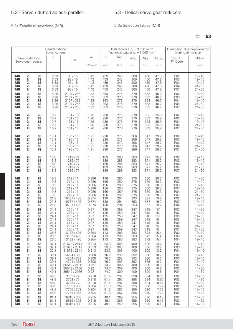
5.3 - Servo riduttori ad assi paralleli 5.3 - Helical servo gear reducers
126 SR13 Edition February 2013
5.3a Tabelle di selezione (MR) 5.3a Selection tables (MR)
CaratteristicheSpecifications
Dati tecnici a n1 = 3 000 min-1
Technical data at n1 = 3 000 min-1Dimensioni di accoppiamento
Mating dimension
Servo riduttoreServo gear reducer
i J1 n2 MN2 MA2 ME2 MA1max Cod. Fl.Fl. Code
Ød×e
10-4 kg m2 min-1 N m N m N m N m mm
MR 2I 63 6,53 98 / 15 1,42 459 243 300 450 47,81) P02 19×40MR 2I 63 6,53 98 / 15 1,42 459 243 300 450 47,81) P03 19×40MR 2I 63 6,53 98 / 15 1,42 459 243 300 450 47,81) P04 19×40MR 2I 63 6,53 98 / 15 1,42 459 243 300 450 47,8 P04 24×50MR 2I 63 6,53 98 / 15 1,42 459 243 300 450 47,8 P07 24×50MR 2I 63 8,26 2107 / 255 1,33 363 276 370 553 46,71) P02 19×40MR 2I 63 8,26 2107 / 255 1,33 363 276 370 553 46,71) P03 19×40MR 2I 63 8,26 2107 / 255 1,33 363 276 370 553 46,71) P04 19×40MR 2I 63 8,26 2107 / 255 1,33 363 276 370 553 46,7 P04 24×50MR 2I 63 8,26 2107 / 255 1,33 363 276 370 553 46,7 P07 24×50
MR 2I 63 10,7 161 / 15 1,26 280 276 370 553 35,9 P02 19×40MR 2I 63 10,7 161 / 15 1,26 280 276 370 553 35,9 P03 19×40MR 2I 63 10,7 161 / 15 1,26 280 276 370 553 35,9 P04 19×40MR 2I 63 10,7 161 / 15 1,26 280 276 370 553 35,9 P04 24×50MR 2I 63 10,7 161 / 15 1,26 280 276 370 553 35,9 P07 24×50
MR 2I 63 13,1 196 / 15 1,21 230 273 366 547 29,2 P02 19×40MR 2I 63 13,1 196 / 15 1,21 230 273 366 547 29,2 P03 19×40MR 2I 63 13,1 196 / 15 1,21 230 273 366 547 29,2 P04 19×40MR 2I 63 13,1 196 / 15 1,21 230 273 366 547 29,2 P04 24×50MR 2I 63 13,1 196 / 15 1,21 230 273 366 547 29,2 P07 24×50
MR 2I 63 15,8 1219 / 77 1 189 286 383 571 25,2 P02 19×40MR 2I 63 15,8 1219 / 77 1 189 286 383 571 25,2 P03 19×40MR 2I 63 15,8 1219 / 77 1 189 286 383 571 25,2 P04 19×40MR 2I 63 15,8 1219 / 77 1 189 286 383 571 25,2 P04 24×50MR 2I 63 15,8 1219 / 77 1 189 286 383 571 25,2 P07 24×50
MR 2I 63 19,3 212 / 11 0,986 156 280 375 560 20,32) P02 14×30MR 2I 63 19,3 212 / 11 0,986 156 280 375 560 20,3 P02 19×40MR 2I 63 19,3 212 / 11 0,986 156 280 375 560 20,3 P03 19×40MR 2I 63 19,3 212 / 11 0,986 156 280 375 560 20,3 P04 19×40MR 2I 63 19,3 212 / 11 0,986 156 280 375 560 20,3 P04 24×50MR 2I 63 19,3 212 / 11 0,986 156 280 375 560 20,3 P07 24×50MR 3I 63 21,8 10787 / 495 0,374 138 294 393 587 19,2 P02 19×40MR 3I 63 21,8 10787 / 495 0,374 138 294 393 587 19,2 P03 19×40MR 3I 63 21,8 10787 / 495 0,374 138 294 393 587 19,2 P04 19×40MR 2I 63 24,1 265 / 11 0,97 125 259 347 518 152) P02 14×30MR 2I 63 24,1 265 / 11 0,97 125 259 347 518 15 P02 19×40MR 2I 63 24,1 265 / 11 0,97 125 259 347 518 152) P03 14×30MR 2I 63 24,1 265 / 11 0,97 125 259 347 518 15 P03 19×40MR 2I 63 24,1 265 / 11 0,97 125 259 347 518 15 P04 19×40MR 2I 63 24,1 265 / 11 0,97 125 259 347 518 15 P04 24×50MR 2I 63 24,1 265 / 11 0,97 125 259 347 518 15 P07 24×50MR 3I 63 26,5 13132 / 495 0,364 113 286 383 572 15,4 P02 19×40MR 3I 63 26,5 13132 / 495 0,364 113 286 383 572 15,4 P03 19×40MR 3I 63 26,5 13132 / 495 0,364 113 286 383 572 15,4 P04 19×40MR 3I 63 32,1 81673 / 2541 0,313 93,3 303 400 600 13,2 P02 19×40MR 3I 63 32,1 81673 / 2541 0,313 93,3 303 400 600 13,2 P03 19×40MR 3I 63 32,1 81673 / 2541 0,313 93,3 303 400 600 13,2 P04 19×40MR 3I 63 39,1 14204 / 363 0,308 76,7 293 392 586 10,7 P02 19×40MR 3I 63 39,1 14204 / 363 0,308 76,7 293 392 586 10,7 P03 19×40MR 3I 63 39,1 14204 / 363 0,308 76,7 293 392 586 10,7 P04 19×40MR 3I 63 40,1 86549 / 2156 0,22 74,7 309 400 600 10,6 P02 14×30MR 3I 63 40,1 86549 / 2156 0,22 74,7 309 400 600 10,6 P03 14×30MR 3I 63 40,1 86549 / 2156 0,22 74,7 309 400 600 10,6 P04 14×30MR 3I 63 48,9 3763 / 77 0,218 61,4 297 398 594 8,66 P02 14×30MR 3I 63 48,9 3763 / 77 0,218 61,4 297 398 594 8,66 P03 14×30MR 3I 63 48,9 3763 / 77 0,218 61,4 297 398 594 8,66 P04 14×30MR 3I 63 48,9 17755 / 363 0,304 61,3 267 355 530 7,72 P02 19×40MR 3I 63 48,9 17755 / 363 0,304 61,3 267 355 530 7,72 P03 19×40MR 3I 63 48,9 17755 / 363 0,304 61,3 267 355 530 7,72 P04 19×40MR 3I 63 61,1 18815 / 308 0,215 49,1 269 355 530 6,18 P02 14×30MR 3I 63 61,1 18815 / 308 0,215 49,1 269 355 530 6,18 P03 14×30MR 3I 63 61,1 18815 / 308 0,215 49,1 269 355 530 6,18 P04 14×30
grand. size 63
i esattoexact

5.3 - Servo riduttori ad assi paralleli 5.3 - Helical servo gear reducers
127SR13 Edition February 2013
5.3a Tabelle di selezione (MR) 5.3a Selection tables (MR)
CaratteristicheSpecifications
Dati tecnici a n1 = 3 000 min-1
Technical data at n1 = 3 000 min-1Dimensioni di accoppiamento
Mating dimension
Servo riduttoreServo gear reducer
i J1 n2 MN2 MA2 ME2 MA1max Cod. Fl.Fl. Code
Ød×e
10-4 kg m2 min-1 N m N m N m N m mm
MR 2I 64 6,86 343 / 50 1,49 437 255 348 512 52,7 P04 24×50MR 2I 64 6,86 343 / 50 1,49 437 255 348 512 52,7 P07 24×50MR 2I 64 7,99 1078 / 135 1,41 376 297 405 596 52,7 P04 24×50MR 2I 64 7,99 1078 / 135 1,41 376 297 405 596 52,7 P07 24×50MR 2I 64 11,2 56 / 5 1,29 268 329 444 657 41,3 P04 24×50MR 2I 64 11,2 56 / 5 1,29 268 329 444 657 41,3 P07 24×50MR 2I 64 13,6 245 / 18 1,24 220 312 416 624 31,9 P04 19×40MR 2I 64 13,6 245 / 18 1,24 220 312 416 624 31,9 P04 24×50MR 2I 64 13,6 245 / 18 1,24 220 312 416 624 31,9 P07 24×50MR 2I 64 16,5 1272 / 77 1,02 182 340 459 680 28,9 P04 19×40MR 2I 64 16,5 1272 / 77 1,02 182 340 459 680 28,9 P04 24×50MR 2I 64 16,5 1272 / 77 1,02 182 340 459 680 28,9 P07 24×50MR 2I 64 20,1 1325 / 66 0,996 149 322 430 644 22,3 P02 19×40MR 2I 64 20,1 1325 / 66 0,996 149 322 430 644 22,3 P04 19×40MR 2I 64 20,1 1325 / 66 0,996 149 322 430 644 22,3 P04 24×50MR 2I 64 20,1 1325 / 66 0,996 149 322 430 644 22,3 P07 24×50MR 3I 64 22,7 3752 / 165 0,381 132 339 430 678 20,1 P02 19×40MR 3I 64 22,7 3752 / 165 0,381 132 339 430 678 20,1 P03 19×40MR 3I 64 22,7 3752 / 165 0,381 132 339 430 678 20,1 P04 19×40MR 2I 64 25,1 1378 / 55 0,976 120 297 397 593 16,5 P02 19×40MR 2I 64 25,1 1378 / 55 0,976 120 297 397 593 16,5 P03 19×40MR 2I 64 25,1 1378 / 55 0,976 120 297 397 593 16,5 P04 19×40MR 2I 64 25,1 1378 / 55 0,976 120 297 397 593 16,5 P04 24×50MR 2I 64 25,1 1378 / 55 0,976 120 297 397 593 16,5 P07 24×50MR 3I 64 27,6 16415 / 594 0,369 109 331 441 661 17 P02 19×40MR 3I 64 27,6 16415 / 594 0,369 109 331 441 661 17 P03 19×40MR 3I 64 27,6 16415 / 594 0,369 109 331 441 661 17 P04 19×40MR 3I 64 33,5 28408 / 847 0,316 89,4 362 475 710 15 P02 19×40MR 3I 64 33,5 28408 / 847 0,316 89,4 362 475 710 15 P03 19×40MR 3I 64 33,5 28408 / 847 0,316 89,4 362 475 710 15 P04 19×40MR 3I 64 40,8 88775 / 2178 0,31 73,6 341 455 683 11,9 P02 19×40MR 3I 64 40,8 88775 / 2178 0,31 73,6 341 455 683 11,9 P03 19×40MR 3I 64 40,8 88775 / 2178 0,31 73,6 341 455 683 11,9 P04 19×40MR 3I 64 41,9 22578 / 539 0,223 71,6 369 475 710 12 P02 14×30MR 3I 64 41,9 22578 / 539 0,223 71,6 369 475 710 12 P03 14×30MR 3I 64 41,9 22578 / 539 0,223 71,6 369 475 710 12 P04 14×30MR 3I 64 50,9 92326 / 1815 0,306 59,0 311 416 621 8,7 P02 19×40MR 3I 64 50,9 92326 / 1815 0,306 59,0 311 416 621 8,7 P03 19×40MR 3I 64 50,9 92326 / 1815 0,306 59,0 311 416 621 8,7 P04 19×40MR 3I 64 50,9 94075 / 1848 0,219 58,9 348 463 695 9,68 P02 14×30MR 3I 64 50,9 94075 / 1848 0,219 58,9 348 463 695 9,68 P03 14×30MR 3I 64 50,9 94075 / 1848 0,219 58,9 348 463 695 9,68 P04 14×30MR 3I 64 63,5 48919 / 770 0,216 47,2 315 422 630 7,07 P02 14×30MR 3I 64 63,5 48919 / 770 0,216 47,2 315 422 630 7,07 P03 14×30MR 3I 64 63,5 48919 / 770 0,216 47,2 315 422 630 7,07 P04 14×30
grand. size 64
i esattoexact
1) In caso di albero servomotore senza linguetta MA1max = 40 Nm.2) In caso di albero servomotore senza linguetta MA1max = 10,6 Nm.
1) In case of keyless servo motor shaft end MA1max = 40 Nm.2) In case of keyless servo motor shaft end MA1max = 10,6 Nm.
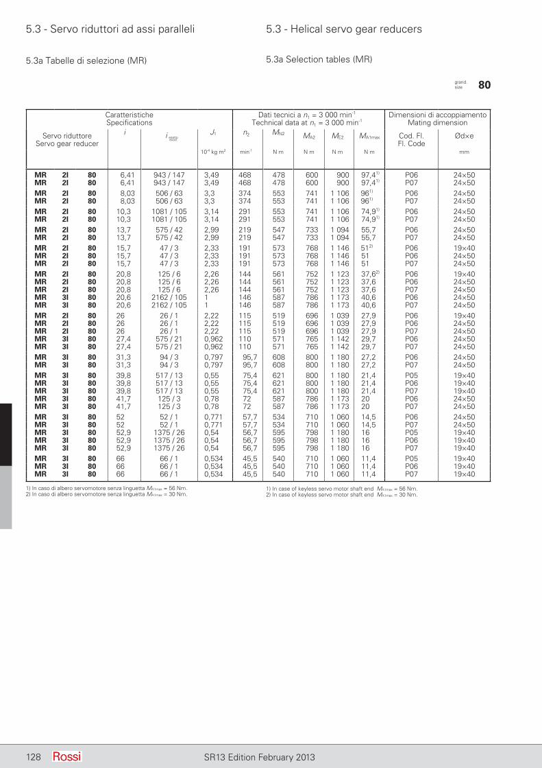
5.3 - Servo riduttori ad assi paralleli 5.3 - Helical servo gear reducers
128 SR13 Edition February 2013
5.3a Tabelle di selezione (MR) 5.3a Selection tables (MR)
CaratteristicheSpecifications
Dati tecnici a n1 = 3 000 min-1
Technical data at n1 = 3 000 min-1Dimensioni di accoppiamento
Mating dimension
Servo riduttoreServo gear reducer
i J1 n2 MN2 MA2 ME2 MA1max Cod. Fl.Fl. Code
Ød×e
10-4 kg m2 min-1 N m N m N m N m mm
MR 2I 80 6,41 943 / 147 3,49 468 478 600 900 97,41) P06 24×50MR 2I 80 6,41 943 / 147 3,49 468 478 600 900 97,41) P07 24×50MR 2I 80 8,03 506 / 63 3,3 374 553 741 1 106 961) P06 24×50MR 2I 80 8,03 506 / 63 3,3 374 553 741 1 106 961) P07 24×50MR 2I 80 10,3 1081 / 105 3,14 291 553 741 1 106 74,91) P06 24×50MR 2I 80 10,3 1081 / 105 3,14 291 553 741 1 106 74,91) P07 24×50MR 2I 80 13,7 575 / 42 2,99 219 547 733 1 094 55,7 P06 24×50MR 2I 80 13,7 575 / 42 2,99 219 547 733 1 094 55,7 P07 24×50MR 2I 80 15,7 47 / 3 2,33 191 573 768 1 146 512) P06 19×40MR 2I 80 15,7 47 / 3 2,33 191 573 768 1 146 51 P06 24×50MR 2I 80 15,7 47 / 3 2,33 191 573 768 1 146 51 P07 24×50MR 2I 80 20,8 125 / 6 2,26 144 561 752 1 123 37,62) P06 19×40MR 2I 80 20,8 125 / 6 2,26 144 561 752 1 123 37,6 P06 24×50MR 2I 80 20,8 125 / 6 2,26 144 561 752 1 123 37,6 P07 24×50MR 3I 80 20,6 2162 / 105 1 146 587 786 1 173 40,6 P06 24×50MR 3I 80 20,6 2162 / 105 1 146 587 786 1 173 40,6 P07 24×50MR 2I 80 26 26 / 1 2,22 115 519 696 1 039 27,9 P06 19×40MR 2I 80 26 26 / 1 2,22 115 519 696 1 039 27,9 P06 24×50MR 2I 80 26 26 / 1 2,22 115 519 696 1 039 27,9 P07 24×50MR 3I 80 27,4 575 / 21 0,962 110 571 765 1 142 29,7 P06 24×50MR 3I 80 27,4 575 / 21 0,962 110 571 765 1 142 29,7 P07 24×50MR 3I 80 31,3 94 / 3 0,797 95,7 608 800 1 180 27,2 P06 24×50MR 3I 80 31,3 94 / 3 0,797 95,7 608 800 1 180 27,2 P07 24×50MR 3I 80 39,8 517 / 13 0,55 75,4 621 800 1 180 21,4 P05 19×40MR 3I 80 39,8 517 / 13 0,55 75,4 621 800 1 180 21,4 P06 19×40MR 3I 80 39,8 517 / 13 0,55 75,4 621 800 1 180 21,4 P07 19×40MR 3I 80 41,7 125 / 3 0,78 72 587 786 1 173 20 P06 24×50MR 3I 80 41,7 125 / 3 0,78 72 587 786 1 173 20 P07 24×50MR 3I 80 52 52 / 1 0,771 57,7 534 710 1 060 14,5 P06 24×50MR 3I 80 52 52 / 1 0,771 57,7 534 710 1 060 14,5 P07 24×50MR 3I 80 52,9 1375 / 26 0,54 56,7 595 798 1 180 16 P05 19×40MR 3I 80 52,9 1375 / 26 0,54 56,7 595 798 1 180 16 P06 19×40MR 3I 80 52,9 1375 / 26 0,54 56,7 595 798 1 180 16 P07 19×40MR 3I 80 66 66 / 1 0,534 45,5 540 710 1 060 11,4 P05 19×40MR 3I 80 66 66 / 1 0,534 45,5 540 710 1 060 11,4 P06 19×40MR 3I 80 66 66 / 1 0,534 45,5 540 710 1 060 11,4 P07 19×40
grand. size 80
i esattoexact
1) In caso di albero servomotore senza linguetta MA1max = 56 Nm.2) In caso di albero servomotore senza linguetta MA1max = 30 Nm.
1) In case of keyless servo motor shaft end MA1max = 56 Nm.2) In case of keyless servo motor shaft end MA1max = 30 Nm.
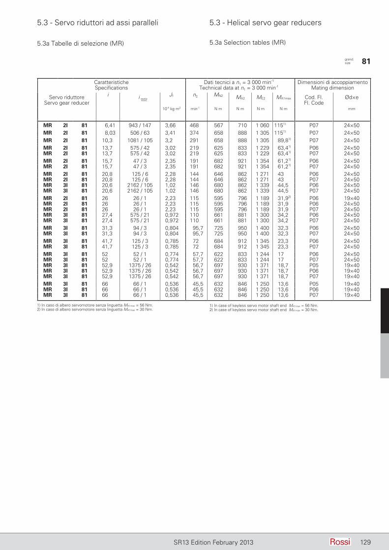
5.3 - Servo riduttori ad assi paralleli 5.3 - Helical servo gear reducers
129SR13 Edition February 2013
5.3a Tabelle di selezione (MR) 5.3a Selection tables (MR)
CaratteristicheSpecifications
Dati tecnici a n1 = 3 000 min-1
Technical data at n1 = 3 000 min-1Dimensioni di accoppiamento
Mating dimension
Servo riduttoreServo gear reducer
i J1 n2 MN2 MA2 ME2 MA1max Cod. Fl.Fl. Code
Ød×e
10-4 kg m2 min-1 N m N m N m N m mm
MR 2I 81 6,41 943 / 147 3,66 468 567 710 1 060 1151) P07 24×50MR 2I 81 8,03 506 / 63 3,41 374 658 888 1 305 1151) P07 24×50MR 2I 81 10,3 1081 / 105 3,2 291 658 888 1 305 89,81) P07 24×50MR 2I 81 13,7 575 / 42 3,02 219 625 833 1 229 63,41) P06 24×50MR 2I 81 13,7 575 / 42 3,02 219 625 833 1 229 63,41) P07 24×50MR 2I 81 15,7 47 / 3 2,35 191 682 921 1 354 61,21) P06 24×50MR 2I 81 15,7 47 / 3 2,35 191 682 921 1 354 61,21) P07 24×50MR 2I 81 20,8 125 / 6 2,28 144 646 862 1 271 43 P06 24×50MR 2I 81 20,8 125 / 6 2,28 144 646 862 1 271 43 P07 24×50MR 3I 81 20,6 2162 / 105 1,02 146 680 862 1 339 44,5 P06 24×50MR 3I 81 20,6 2162 / 105 1,02 146 680 862 1 339 44,5 P07 24×50MR 2I 81 26 26 / 1 2,23 115 595 796 1 189 31,92) P06 19×40MR 2I 81 26 26 / 1 2,23 115 595 796 1 189 31,9 P06 24×50MR 2I 81 26 26 / 1 2,23 115 595 796 1 189 31,9 P07 24×50MR 3I 81 27,4 575 / 21 0,972 110 661 881 1 300 34,2 P06 24×50MR 3I 81 27,4 575 / 21 0,972 110 661 881 1 300 34,2 P07 24×50MR 3I 81 31,3 94 / 3 0,804 95,7 725 950 1 400 32,3 P06 24×50MR 3I 81 31,3 94 / 3 0,804 95,7 725 950 1 400 32,3 P07 24×50MR 3I 81 41,7 125 / 3 0,785 72 684 912 1 345 23,3 P06 24×50MR 3I 81 41,7 125 / 3 0,785 72 684 912 1 345 23,3 P07 24×50MR 3I 81 52 52 / 1 0,774 57,7 622 833 1 244 17 P06 24×50MR 3I 81 52 52 / 1 0,774 57,7 622 833 1 244 17 P07 24×50MR 3I 81 52,9 1375 / 26 0,542 56,7 697 930 1 371 18,7 P05 19×40MR 3I 81 52,9 1375 / 26 0,542 56,7 697 930 1 371 18,7 P06 19×40MR 3I 81 52,9 1375 / 26 0,542 56,7 697 930 1 371 18,7 P07 19×40MR 3I 81 66 66 / 1 0,536 45,5 632 846 1 250 13,6 P05 19×40MR 3I 81 66 66 / 1 0,536 45,5 632 846 1 250 13,6 P06 19×40MR 3I 81 66 66 / 1 0,536 45,5 632 846 1 250 13,6 P07 19×40
grand. size 81
i esattoexact
1) In caso di albero servomotore senza linguetta MA1max = 56 Nm.2) In caso di albero servomotore senza linguetta MA1max = 30 Nm.
1) In case of keyless servo motor shaft end MA1max = 56 Nm.2) In case of keyless servo motor shaft end MA1max = 30 Nm.
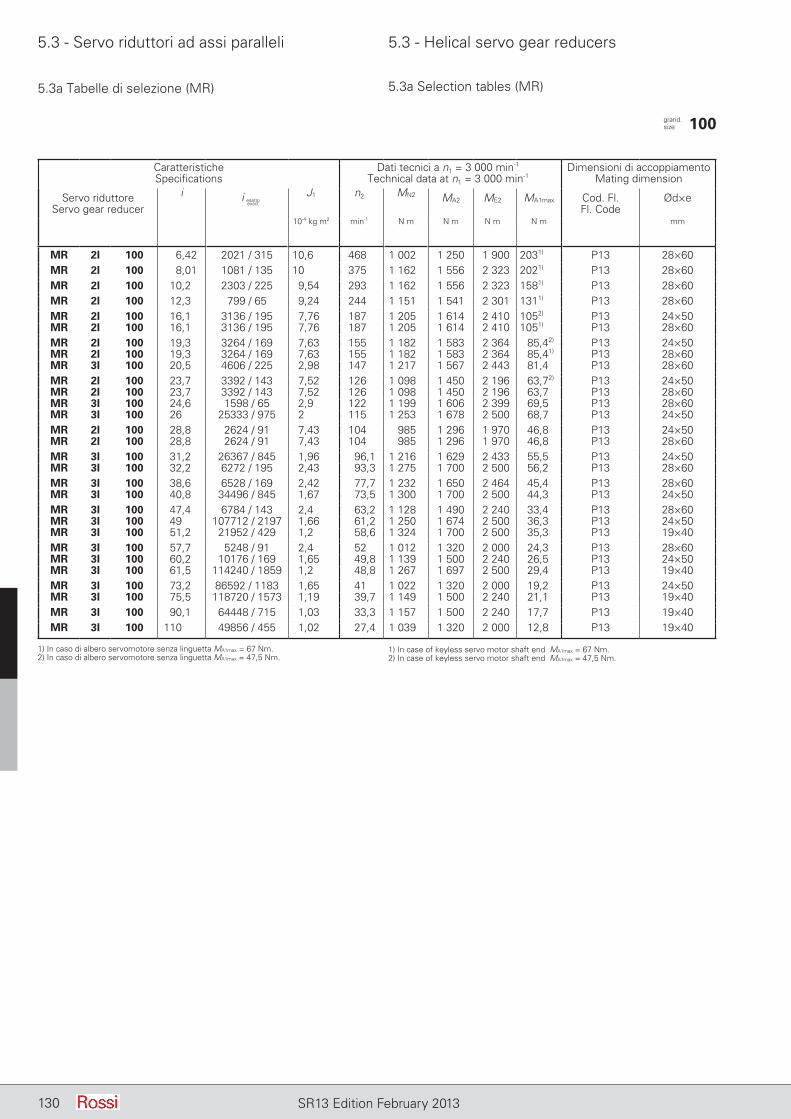
5.3 - Servo riduttori ad assi paralleli 5.3 - Helical servo gear reducers
130 SR13 Edition February 2013
5.3a Tabelle di selezione (MR) 5.3a Selection tables (MR)
CaratteristicheSpecifications
Dati tecnici a n1 = 3 000 min-1
Technical data at n1 = 3 000 min-1Dimensioni di accoppiamento
Mating dimension
Servo riduttoreServo gear reducer
i J1 n2 MN2 MA2 ME2 MA1max Cod. Fl.Fl. Code
Ød×e
10-4 kg m2 min-1 N m N m N m N m mm
MR 2I 100 6,42 2021 / 315 10,6 468 1 002 1 250 1 900 2031) P13 28×60MR 2I 100 8,01 1081 / 135 10 375 1 162 1 556 2 323 2021) P13 28×60MR 2I 100 10,2 2303 / 225 9,54 293 1 162 1 556 2 323 1581) P13 28×60MR 2I 100 12,3 799 / 65 9,24 244 1 151 1 541 2 301 1311) P13 28×60MR 2I 100 16,1 3136 / 195 7,76 187 1 205 1 614 2 410 1052) P13 24×50MR 2I 100 16,1 3136 / 195 7,76 187 1 205 1 614 2 410 1051) P13 28×60MR 2I 100 19,3 3264 / 169 7,63 155 1 182 1 583 2 364 85,42) P13 24×50MR 2I 100 19,3 3264 / 169 7,63 155 1 182 1 583 2 364 85,41) P13 28×60MR 3I 100 20,5 4606 / 225 2,98 147 1 217 1 567 2 443 81,4 P13 28×60MR 2I 100 23,7 3392 / 143 7,52 126 1 098 1 450 2 196 63,72) P13 24×50MR 2I 100 23,7 3392 / 143 7,52 126 1 098 1 450 2 196 63,7 P13 28×60MR 3I 100 24,6 1598 / 65 2,9 122 1 199 1 606 2 399 69,5 P13 28×60MR 3I 100 26 25333 / 975 2 115 1 253 1 678 2 500 68,7 P13 24×50MR 2I 100 28,8 2624 / 91 7,43 104 985 1 296 1 970 46,8 P13 24×50MR 2I 100 28,8 2624 / 91 7,43 104 985 1 296 1 970 46,8 P13 28×60MR 3I 100 31,2 26367 / 845 1,96 96,1 1 216 1 629 2 433 55,5 P13 24×50MR 3I 100 32,2 6272 / 195 2,43 93,3 1 275 1 700 2 500 56,2 P13 28×60MR 3I 100 38,6 6528 / 169 2,42 77,7 1 232 1 650 2 464 45,4 P13 28×60MR 3I 100 40,8 34496 / 845 1,67 73,5 1 300 1 700 2 500 44,3 P13 24×50MR 3I 100 47,4 6784 / 143 2,4 63,2 1 128 1 490 2 240 33,4 P13 28×60MR 3I 100 49 107712 / 2197 1,66 61,2 1 250 1 674 2 500 36,3 P13 24×50MR 3I 100 51,2 21952 / 429 1,2 58,6 1 324 1 700 2 500 35,3 P13 19×40MR 3I 100 57,7 5248 / 91 2,4 52 1 012 1 320 2 000 24,3 P13 28×60MR 3I 100 60,2 10176 / 169 1,65 49,8 1 139 1 500 2 240 26,5 P13 24×50MR 3I 100 61,5 114240 / 1859 1,2 48,8 1 267 1 697 2 500 29,4 P13 19×40MR 3I 100 73,2 86592 / 1183 1,65 41 1 022 1 320 2 000 19,2 P13 24×50MR 3I 100 75,5 118720 / 1573 1,19 39,7 1 149 1 500 2 240 21,1 P13 19×40MR 3I 100 90,1 64448 / 715 1,03 33,3 1 157 1 500 2 240 17,7 P13 19×40MR 3I 100 110 49856 / 455 1,02 27,4 1 039 1 320 2 000 12,8 P13 19×40
grand. size 100
i esattoexact
1) In caso di albero servomotore senza linguetta MA1max = 67 Nm.2) In caso di albero servomotore senza linguetta MA1max = 47,5 Nm.
1) In case of keyless servo motor shaft end MA1max = 67 Nm.2) In case of keyless servo motor shaft end MA1max = 47,5 Nm.
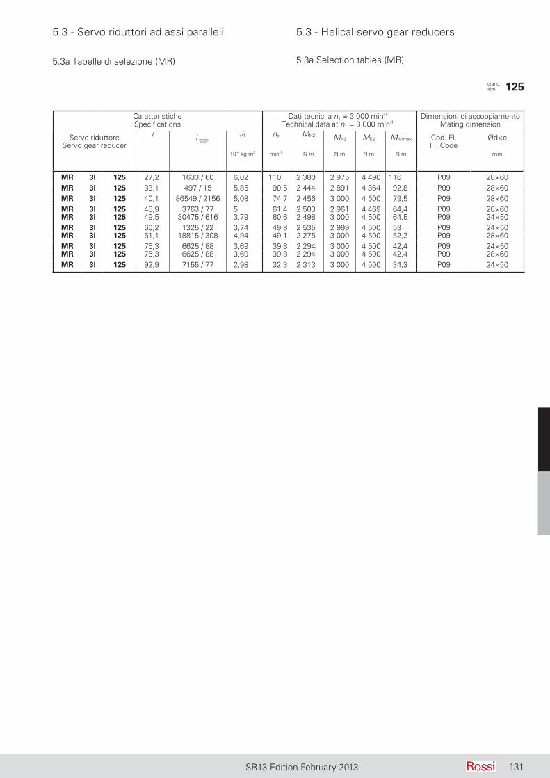
5.3 - Servo riduttori ad assi paralleli 5.3 - Helical servo gear reducers
131SR13 Edition February 2013
5.3a Tabelle di selezione (MR) 5.3a Selection tables (MR)
CaratteristicheSpecifications
Dati tecnici a n1 = 3 000 min-1
Technical data at n1 = 3 000 min-1Dimensioni di accoppiamento
Mating dimension
Servo riduttoreServo gear reducer
i J1 n2 MN2 MA2 ME2 MA1max Cod. Fl.Fl. Code
Ød×e
10-4 kg m2 min-1 N m N m N m N m mm
MR 3I 125 27,2 1633 / 60 6,02 110 2 380 2 975 4 490 116 P09 28×60MR 3I 125 33,1 497 / 15 5,85 90,5 2 444 2 891 4 364 92,8 P09 28×60MR 3I 125 40,1 86549 / 2156 5,08 74,7 2 456 3 000 4 500 79,5 P09 28×60MR 3I 125 48,9 3763 / 77 5 61,4 2 503 2 961 4 469 64,4 P09 28×60MR 3I 125 49,5 30475 / 616 3,79 60,6 2 498 3 000 4 500 64,5 P09 24×50MR 3I 125 60,2 1325 / 22 3,74 49,8 2 535 2 999 4 500 53 P09 24×50MR 3I 125 61,1 18815 / 308 4,94 49,1 2 275 3 000 4 500 52,2 P09 28×60MR 3I 125 75,3 6625 / 88 3,69 39,8 2 294 3 000 4 500 42,4 P09 24×50MR 3I 125 75,3 6625 / 88 3,69 39,8 2 294 3 000 4 500 42,4 P09 28×60MR 3I 125 92,9 7155 / 77 2,98 32,3 2 313 3 000 4 500 34,3 P09 24×50
grand. size 125
i esattoexact
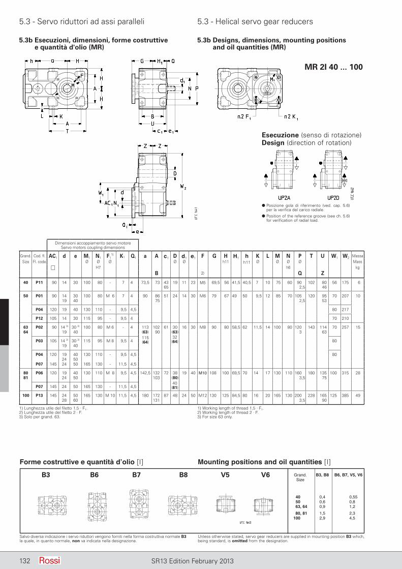
5.3 - Servo riduttori ad assi paralleli 5.3 - Helical servo gear reducers
132 SR13 Edition February 2013
5.3b Esecuzioni, dimensioni, forme costruttive e quantità d'olio (MR)
5.3b Designs, dimensions, mounting positions and oil quantities (MR)
MR 2I 40 ... 100
Esecuzione (senso di rotazione)Design (direction of rotation)
d Posizione gola di riferimento (ved. cap. 5.6) per la verifica del carico radiale.
d Position of the reference groove (see ch. 5.6) for verification of radial load.
Salvo diversa indicazione i servo riduttori vengono forniti nella forma costruttiva normale B3 la quale, in quanto normale, non va indicata nella designazione.
Unless otherwise stated, servo gear reducers are supplied in mounting position B3 which, being standard, is omitted from the designation.
1) Lunghezza utile del filetto 1,5 · F1.2) Lunghezza utile del filetto 2 · F.3) Solo per grand. 63.
1) Working length of thread 1,5 · F1.2) Working length of thread 2 · F.3) For size 63 only.
Forme costruttive e quantità d’olio [I] Mounting positions and oil quantities [I] Grand. B3, B8 B6, B7, V5, V6 Size
40, 1 0,4 0,55 50, 1 0,6 0,80 63, 64 0,9 1,20 80, 81 1,5 2,30 100, 01 2,9 4,50
B3 B6 B7 B8 V5 V6
Dimensioni accoppiamento servo motoreServo motors coupling dimensions
Grand. Cod. fl. AC1 d e M1 N1 F11) K1 Q1 a A c1 D d1 e1 F G H H1 h K L M N P T U W1 W2 Massa
Size Fl. code Ø Ø Ø Ø Ø h11 h11 Ø Ø Ø Ø Mass H7 h6 kg
B 2) Q Z
40 P11 90 14 30 100 80 - 7 4 73,5 73 43 19 11 23 M5 69,5 56 41,5 40,5 7 10 75 60 90 102 80 56 175 665 2,5 46
50 P01 90 14 30 100 80 M06 7 4 90 86 51 24 14 30 M6 79 67 49 50 9,5 12 85 70 105 120 95 70 207 1019 40 75 2,5 53
P04 120 19 40 130 110 - 9,5 4,5 80 217
P12 105 14 30 115 95 - 9,5 4 70 210
63 P02 90 14 3) 30 3) 100 80 M 6 - 4 113 102 61 30 16 30 M8 90 80 58,5 62 11,5 14 100 80 120 143 114 70 257 1564 19 40 (63) 90 (63) 3 63
P03 105 14 3) 30 3) 115 95 M 8 9,5 4 8019 40
P04 120 19 40 130 110 - 9,5 4,5 8024 50
P07 145 24 50 165 130 - 11,5 4,5
80 P06 120 19 40 130 110 M08 9,5 4,5 142,5 132 72 38 19 40 M10 108 100 69,5 70 14 17 130 110 160 180 135 100 315 2881 24 50 103 (80) 3,5 75
P07 145 24 50 165 130 - 11,5 4,5
100 P13 145 24 50 165 130 M 10 11,5 4,5 180 172 87 48 24 50 M12 130 125 84,5 80 16 20 165 130 200 228 165 125 385 4928 60 131 3,5 90
115(64)
32(64)
40(81)
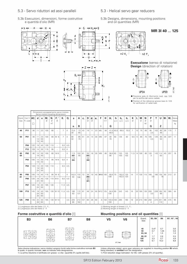
5.3 - Servo riduttori ad assi paralleli 5.3 - Helical servo gear reducers
133SR13 Edition February 2013
MR 3I 40 ... 125
5.3b Esecuzioni, dimensioni, forme costruttive e quantità d'olio (MR)
5.3b Designs, dimensions, mounting positions and oil quantities (MR)
Esecuzione (senso di rotazione)Design (direction of rotation)
d Posizione gola di riferimento (ved. cap. 5.6) per la verifica del carico radiale.
d Position of the reference groove (see ch. 5.6) for verification of radial load.
1) Lunghezza utile del filetto 1,5 · F1.2) Lunghezza utile del filetto 2 · F.
1) Working length of thread 1,5 · F1.2) Working length of thread 2 · F.
Salvo diversa indicazione i servo riduttori vengono forniti nella forma costruttiva normale B3 la quale, in quanto normale, non va indicata nella designazione.1) La prima riduzione è lubrificata con grasso «a vita» (quantità 5% quella dell’olio).
Unless otherwise stated, servo gear reducers are supplied in mounting position B3 which, being standard, is omitted from the designation.1) First reduction stage lubricated «for life» with grease (5% oil quantity).
Forme costruttive e quantità d’olio [I] Mounting positions and oil quantities [I] Grand. B3, B8 B6 B7, V51), V6 Size
40, 1 0,47 0,70 0,6 50, 1 0,70 1,05 0,9 63, 64 1,00 1,50 1,3 80, 81 1,70 2,90 2,5 100, 01 3,30 5,70 4,9 125, 01 6,10 10,20 8,8
B3 B6 B7 B8 V5 V6
Dimensioni accoppiamento servo motoreServo motors coupling dimensions
Grand. Cod. fl. AC1 d e M1 N1 F11) K1 Q1 a A c1 D d1 e1 F H H1 h h0 h1 K L M N P T U W1 W2 Massa
Size Fl. code Ø Ø Ø Ø Ø h11 h11 h11 h11 Ø Ø Ø Ø Mass H7 h6 kg
a1 B 2) G Q Z
40 P11 90 11 23 100 80 - 7 4 73,5 73 43 19 11 23 M5 56 41,5 40,5 99,5 70,5 7 10 75 60 95 102 80 26 170 730,0 65 69,5 2,5 46
50 P01 90 11 23 100 80 M06 7 4 90,0 85 51 24 14 30 M6 67 49 50 125 82 9,5 12 85 70 105 120 95 35 207 1114 30 32,0 75 79 2,5 5319 40
P04 120 19 40 130 110 - 9,5 4,5
P12 105 14 30 115 95 - 9,5 4
63 P02 90 14 30 100 80 M 6 - 4 113 102 61 30 16 30 M8 80 58,5 62 153 102 11,5 14 100 80 120 143 114 40 257 1864 19 40 (63) 90 (63) 90 155 102 3 63
P03 105 14 30 115 95 M 8 9,5 419 40
P04 120 14 30 130 110 - 9,5 4,519 4024 50
80 P05 105 19 40 115 95 M08 - 4 142,5 132 72 38 19 40 M10 100 69,5 70 192,5 120 14 17 130 110 160 180 135 50 313 31108 192,5 120
P06 120 19 40 130 110 M 8 9,5 4,524 50
P07 145 19 40 165 130 - 11,5 4,524 50
100 P13 145 19 40 165 130 M 10 11,5 4,5 180 172 87 48 24 50 M12 125 84,5 80 242 143 16 20 165 130 200 228 165 62 385 5424 50 63 131 130 3,5 9028 60
125 P09 145 24 50 165 130 M 10 - 4,5 225 212 107 60 28 60 4) 150 103,5 100 295 180 18 23 215 180 250 274 201 86 475 9528 60 80 162 159 4 110
81
115(64)
32(64)
50 10640(81)
3,5 75(80)
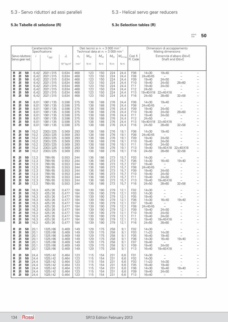
5.3 - Servo riduttori ad assi paralleli 5.3 - Helical servo gear reducers
134 SR13 Edition February 2013
5.3c Tabelle di selezione (R) 5.3c Selection tables (R)
CaratteristicheSpecifications
Dati tecnici a n1 = 3 000 min-1
Technical data at n1 = 3 000 min-1Dimensioni di accoppiamento
Mating dimensionsServo riduttoreServo gear red.
i J1 n2 MN2 MA2 ME2 MA1max Cod. fl. Fl. Code
Estremità d’albero Ød×EShaft end Ød×E
10-4 kg m2 min-1 N m N m N m N m
R 2I 50 6,42 2021 / 315 0,634 468 123 150 224 24,4 F06 14×30 19×40 – –R 2I 50 6,42 2021 / 315 0,634 468 123 150 224 24,4 F08 24×40-X5 – – –R 2I 50 6,42 2021 / 315 0,634 468 123 150 224 24,4 F09 19×40 24×50 – –R 2I 50 6,42 2021 / 315 0,634 468 123 150 224 24,4 F10 19×40 24×50 28×60 –R 2I 50 6,42 2021 / 315 0,634 468 123 150 224 24,4 F11 19×40 24×50 – –R 2I 50 6,42 2021 / 315 0,634 468 123 150 224 24,4 F12 24×50 – – –R 2I 50 6,42 2021 / 315 0,634 468 123 150 224 24,4 F13 19×40-X18 22×40-X18 – –R 2I 50 6,42 2021 / 315 0,634 468 123 150 224 24,4 F16 24×50 28×60 32×58 –
R 2I 50 8,01 1081 / 135 0,598 375 138 188 276 24,4 F06 14×30 19×40 – –R 2I 50 8,01 1081 / 135 0,598 375 138 188 276 24,4 F08 24×40-X5 – – –R 2I 50 8,01 1081 / 135 0,598 375 138 188 276 24,4 F09 19×40 24×50 – –R 2I 50 8,01 1081 / 135 0,598 375 138 188 276 24,4 F10 19×40 24×50 28×60 –R 2I 50 8,01 1081 / 135 0,598 375 138 188 276 24,4 F11 19×40 24×50 – –R 2I 50 8,01 1081 / 135 0,598 375 138 188 276 24,4 F12 24×50 – – –R 2I 50 8,01 1081 / 135 0,598 375 138 188 276 24,4 F13 19×40-X18 22×40-X18 – –R 2I 50 8,01 1081 / 135 0,598 375 138 188 276 24,4 F16 24×50 28×60 32×58 –
R 2I 50 10,2 2303 / 225 0,569 293 138 188 276 19,1 F06 14×30 19×40 – –R 2I 50 10,2 2303 / 225 0,569 293 138 188 276 19,1 F08 24×40-X5 – – –R 2I 50 10,2 2303 / 225 0,569 293 138 188 276 19,1 F09 19×40 24×50 – –R 2I 50 10,2 2303 / 225 0,569 293 138 188 276 19,1 F10 19×40 24×50 – –R 2I 50 10,2 2303 / 225 0,569 293 138 188 276 19,1 F11 19×40 24×50 – –R 2I 50 10,2 2303 / 225 0,569 293 138 188 276 19,1 F13 19×40 19×40-X18 22×40-X18 –R 2I 50 10,2 2303 / 225 0,569 293 138 188 276 19,1 F16 24×50 28×60 32×58 –
R 2I 50 12,3 799 / 65 0,553 244 136 186 273 15,7 F03 14×30 – – –R 2I 50 12,3 799 / 65 0,553 244 136 186 273 15,7 F06 14×30 16×40 19×40 –R 2I 50 12,3 799 / 65 0,553 244 136 186 273 15,7 F07 19×40 – – –R 2I 50 12,3 799 / 65 0,553 244 136 186 273 15,7 F08 24×40-X5 – – –R 2I 50 12,3 799 / 65 0,553 244 136 186 273 15,7 F09 19×40 24×50 – –R 2I 50 12,3 799 / 65 0,553 244 136 186 273 15,7 F10 19×40 24×50 – –R 2I 50 12,3 799 / 65 0,553 244 136 186 273 15,7 F11 19×40 24×50 – –R 2I 50 12,3 799 / 65 0,553 244 136 186 273 15,7 F13 19×40 19×40-X18 – –R 2I 50 12,3 799 / 65 0,553 244 136 186 273 15,7 F16 24×50 28×60 32×58 –
R 2I 50 16,3 425 / 26 0,477 184 139 190 279 12,1 F02 14×30 – – –R 2I 50 16,3 425 / 26 0,477 184 139 190 279 12,1 F03 14×30 – – –R 2I 50 16,3 425 / 26 0,477 184 139 190 279 12,1 F05 19×40 – – –R 2I 50 16,3 425 / 26 0,477 184 139 190 279 12,1 F06 14×30 16×40 19×40 –R 2I 50 16,3 425 / 26 0,477 184 139 190 279 12,1 F07 19×40 – – –R 2I 50 16,3 425 / 26 0,477 184 139 190 279 12,1 F08 24×40-X5 – – –R 2I 50 16,3 425 / 26 0,477 184 139 190 279 12,1 F09 19×40 24×50 – –R 2I 50 16,3 425 / 26 0,477 184 139 190 279 12,1 F10 19×40 24×50 – –R 2I 50 16,3 425 / 26 0,477 184 139 190 279 12,1 F11 19×40 24×50 – –R 2I 50 16,3 425 / 26 0,477 184 139 190 279 12,1 F13 19×40 19×40-X18 – –R 2I 50 16,3 425 / 26 0,477 184 139 190 279 12,1 F16 24×50 28×60 – –
R 2I 50 20,1 1325 / 66 0,469 149 129 175 258 9,1 F02 14×30 – – –R 2I 50 20,1 1325 / 66 0,469 149 129 175 258 9,1 F03 11×23 14×30 – –R 2I 50 20,1 1325 / 66 0,469 149 129 175 258 9,1 F05 16×40 19×40 – –R 2I 50 20,1 1325 / 66 0,469 149 129 175 258 9,1 F06 14×30 16×40 19×40 –R 2I 50 20,1 1325 / 66 0,469 149 129 175 258 9,1 F07 19×40 – – –R 2I 50 20,1 1325 / 66 0,469 149 129 175 258 9,1 F09 19×40 24×50 – –R 2I 50 20,1 1325 / 66 0,469 149 129 175 258 9,1 F13 16×40 19×40-X18 – –
R 2I 50 24,4 1025 / 42 0,464 123 115 154 231 6,6 F01 14×30 – – –R 2I 50 24,4 1025 / 42 0,464 123 115 154 231 6,6 F02 14×30 – – –R 2I 50 24,4 1025 / 42 0,464 123 115 154 231 6,6 F03 11×23 14×30 – –R 2I 50 24,4 1025 / 42 0,464 123 115 154 231 6,6 F05 16×40 19×40 – –R 2I 50 24,4 1025 / 42 0,464 123 115 154 231 6,6 F06 14×30 16×40 19×40 –R 2I 50 24,4 1025 / 42 0,464 123 115 154 231 6,6 F09 19×40 24×50 – –R 2I 50 24,4 1025 / 42 0,464 123 115 154 231 6,6 F13 16×40 – – –
i esattoexact
grand. size 50
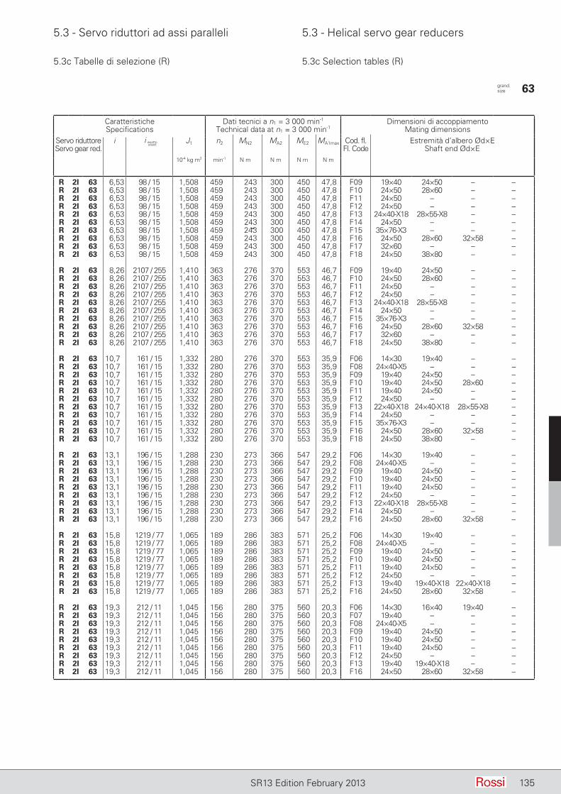
5.3 - Servo riduttori ad assi paralleli 5.3 - Helical servo gear reducers
135SR13 Edition February 2013
5.3c Tabelle di selezione (R) 5.3c Selection tables (R)
CaratteristicheSpecifications
Dati tecnici a n1 = 3 000 min-1
Technical data at n1 = 3 000 min-1Dimensioni di accoppiamento
Mating dimensionsServo riduttoreServo gear red.
i J1 n2 MN2 MA2 ME2 MA1max Cod. fl. Fl. Code
Estremità d’albero Ød×EShaft end Ød×E
10-4 kg m2 min-1 N m N m N m N m
R 2I 63 6,53 98 / 15 1,508 459 243 300 450 47,8 F09 19×40 24×50 – –R 2I 63 6,53 98 / 15 1,508 459 243 300 450 47,8 F10 24×50 28×60 – –R 2I 63 6,53 98 / 15 1,508 459 243 300 450 47,8 F11 24×50 – – –R 2I 63 6,53 98 / 15 1,508 459 243 300 450 47,8 F12 24×50 – – –R 2I 63 6,53 98 / 15 1,508 459 243 300 450 47,8 F13 24×40-X18 28×55-X8 – –R 2I 63 6,53 98 / 15 1,508 459 243 300 450 47,8 F14 24×50 – – –R 2I 63 6,53 98 / 15 1,508 459 243 300 450 47,8 F15 35×76-X3 – – –R 2I 63 6,53 98 / 15 1,508 459 243 300 450 47,8 F16 24×50 28×60 32×58 –R 2I 63 6,53 98 / 15 1,508 459 243 300 450 47,8 F17 32×60 – – –R 2I 63 6,53 98 / 15 1,508 459 243 300 450 47,8 F18 24×50 38×80 – –
R 2I 63 8,26 2107 / 255 1,410 363 276 370 553 46,7 F09 19×40 24×50 – –R 2I 63 8,26 2107 / 255 1,410 363 276 370 553 46,7 F10 24×50 28×60 – –R 2I 63 8,26 2107 / 255 1,410 363 276 370 553 46,7 F11 24×50 – – –R 2I 63 8,26 2107 / 255 1,410 363 276 370 553 46,7 F12 24×50 – – –R 2I 63 8,26 2107 / 255 1,410 363 276 370 553 46,7 F13 24×40-X18 28×55-X8 – –R 2I 63 8,26 2107 / 255 1,410 363 276 370 553 46,7 F14 24×50 – – –R 2I 63 8,26 2107 / 255 1,410 363 276 370 553 46,7 F15 35×76-X3 – – –R 2I 63 8,26 2107 / 255 1,410 363 276 370 553 46,7 F16 24×50 28×60 32×58 –R 2I 63 8,26 2107 / 255 1,410 363 276 370 553 46,7 F17 32×60 – – –R 2I 63 8,26 2107 / 255 1,410 363 276 370 553 46,7 F18 24×50 38×80 – –
R 2I 63 10,7 161 / 15 1,332 280 276 370 553 35,9 F06 14×30 19×40 – –R 2I 63 10,7 161 / 15 1,332 280 276 370 553 35,9 F08 24×40-X5 – – –R 2I 63 10,7 161 / 15 1,332 280 276 370 553 35,9 F09 19×40 24×50 – –R 2I 63 10,7 161 / 15 1,332 280 276 370 553 35,9 F10 19×40 24×50 28×60 –R 2I 63 10,7 161 / 15 1,332 280 276 370 553 35,9 F11 19×40 24×50 – –R 2I 63 10,7 161 / 15 1,332 280 276 370 553 35,9 F12 24×50 – – –R 2I 63 10,7 161 / 15 1,332 280 276 370 553 35,9 F13 22×40-X18 24×40-X18 28×55-X8 –R 2I 63 10,7 161 / 15 1,332 280 276 370 553 35,9 F14 24×50 – – –R 2I 63 10,7 161 / 15 1,332 280 276 370 553 35,9 F15 35×76-X3 – – –R 2I 63 10,7 161 / 15 1,332 280 276 370 553 35,9 F16 24×50 28×60 32×58 –R 2I 63 10,7 161 / 15 1,332 280 276 370 553 35,9 F18 24×50 38×80 – –
R 2I 63 13,1 196 / 15 1,288 230 273 366 547 29,2 F06 14×30 19×40 – –R 2I 63 13,1 196 / 15 1,288 230 273 366 547 29,2 F08 24×40-X5 – – –R 2I 63 13,1 196 / 15 1,288 230 273 366 547 29,2 F09 19×40 24×50 – –R 2I 63 13,1 196 / 15 1,288 230 273 366 547 29,2 F10 19×40 24×50 – –R 2I 63 13,1 196 / 15 1,288 230 273 366 547 29,2 F11 19×40 24×50 – –R 2I 63 13,1 196 / 15 1,288 230 273 366 547 29,2 F12 24×50 – – –R 2I 63 13,1 196 / 15 1,288 230 273 366 547 29,2 F13 22×40-X18 28×55-X8 – –R 2I 63 13,1 196 / 15 1,288 230 273 366 547 29,2 F14 24×50 – – –R 2I 63 13,1 196 / 15 1,288 230 273 366 547 29,2 F16 24×50 28×60 32×58 –
R 2I 63 15,8 1219 / 77 1,065 189 286 383 571 25,2 F06 14×30 19×40 – –R 2I 63 15,8 1219 / 77 1,065 189 286 383 571 25,2 F08 24×40-X5 – – –R 2I 63 15,8 1219 / 77 1,065 189 286 383 571 25,2 F09 19×40 24×50 – –R 2I 63 15,8 1219 / 77 1,065 189 286 383 571 25,2 F10 19×40 24×50 – –R 2I 63 15,8 1219 / 77 1,065 189 286 383 571 25,2 F11 19×40 24×50 – –R 2I 63 15,8 1219 / 77 1,065 189 286 383 571 25,2 F12 24×50 – – –R 2I 63 15,8 1219 / 77 1,065 189 286 383 571 25,2 F13 19×40 19×40-X18 22×40-X18 –R 2I 63 15,8 1219 / 77 1,065 189 286 383 571 25,2 F16 24×50 28×60 32×58 –
R 2I 63 19,3 212 / 11 1,045 156 280 375 560 20,3 F06 14×30 16×40 19×40 –R 2I 63 19,3 212 / 11 1,045 156 280 375 560 20,3 F07 19×40 – – –R 2I 63 19,3 212 / 11 1,045 156 280 375 560 20,3 F08 24×40-X5 – – –R 2I 63 19,3 212 / 11 1,045 156 280 375 560 20,3 F09 19×40 24×50 – –R 2I 63 19,3 212 / 11 1,045 156 280 375 560 20,3 F10 19×40 24×50 – –R 2I 63 19,3 212 / 11 1,045 156 280 375 560 20,3 F11 19×40 24×50 – –R 2I 63 19,3 212 / 11 1,045 156 280 375 560 20,3 F12 24×50 – – –R 2I 63 19,3 212 / 11 1,045 156 280 375 560 20,3 F13 19×40 19×40-X18 – –R 2I 63 19,3 212 / 11 1,045 156 280 375 560 20,3 F16 24×50 28×60 32×58 –
––
i esattoexact
grand. size 63
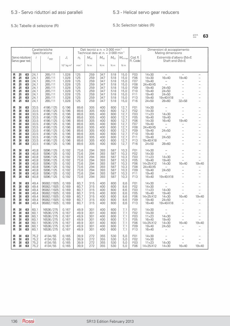
5.3 - Servo riduttori ad assi paralleli 5.3 - Helical servo gear reducers
136 SR13 Edition February 2013
5.3c Tabelle di selezione (R) 5.3c Selection tables (R)
CaratteristicheSpecifications
Dati tecnici a n1 = 3 000 min-1
Technical data at n1 = 3 000 min-1Dimensioni di accoppiamento
Mating dimensionsServo riduttoreServo gear red.
i J1 n2 MN2 MA2 ME2 MA1max Cod. fl. Fl. Code
Estremità d’albero Ød×EShaft end Ød×E
10-4 kg m2 min-1 N m N m N m N m
R 2I 63 24,1 265 / 11 1,028 125 259 347 518 15,0 F03 14×30 – – –R 2I 63 24,1 265 / 11 1,028 125 259 347 518 15,0 F06 14×30 16×40 19×40 –R 2I 63 24,1 265 / 11 1,028 125 259 347 518 15,0 F07 19×40 – – –R 2I 63 24,1 265 / 11 1,028 125 259 347 518 15,0 F08 24×40-X5 – – –R 2I 63 24,1 265 / 11 1,028 125 259 347 518 15,0 F09 19×40 24×50 – –R 2I 63 24,1 265 / 11 1,028 125 259 347 518 15,0 F10 19×40 24×50 – –R 2I 63 24,1 265 / 11 1,028 125 259 347 518 15,0 F11 19×40 24×50 – –R 2I 63 24,1 265 / 11 1,028 125 259 347 518 15,0 F13 19×40 19×40-X18 – –R 2I 63 24,1 265 / 11 1,028 125 259 347 518 15,0 F16 24×50 28×60 32×58 –
R 3I 63 33,5 4186 / 125 0,196 89,6 305 400 600 12,7 F01 14×30 – – –R 3I 63 33,5 4186 / 125 0,196 89,6 305 400 600 12,7 F02 14×30 – – –R 3I 63 33,5 4186 / 125 0,196 89,6 305 400 600 12,7 F03 11×23 14×30 – –R 3I 63 33,5 4186 / 125 0,196 89,6 305 400 600 12,7 F05 16×40 19×40 – –R 3I 63 33,5 4186 / 125 0,196 89,6 305 400 600 12,7 F06 14×30 16×40 19×40 –R 3I 63 33,5 4186 / 125 0,196 89,6 305 400 600 12,7 F07 19×40 – – –R 3I 63 33,5 4186 / 125 0,196 89,6 305 400 600 12,7 F08 24×40-X5 – – –R 3I 63 33,5 4186 / 125 0,196 89,6 305 400 600 12,7 F09 19×40 24×50 – –R 3I 63 33,5 4186 / 125 0,196 89,6 305 400 600 12,7 F10 19×40 – – –R 3I 63 33,5 4186 / 125 0,196 89,6 305 400 600 12,7 F11 19×40 24×50 – –R 3I 63 33,5 4186 / 125 0,196 89,6 305 400 600 12,7 F13 19×40-X18 – – –R 3I 63 33,5 4186 / 125 0,196 89,6 305 400 600 12,7 F16 24×50 28×60 – –
R 3I 63 40,8 5096 / 125 0,192 73,6 294 393 587 10,3 F01 14×30 – – –R 3I 63 40,8 5096 / 125 0,192 73,6 294 393 587 10,3 F02 14×30 – – –R 3I 63 40,8 5096 / 125 0,192 73,6 294 393 587 10,3 F03 11×23 14×30 – –R 3I 63 40,8 5096 / 125 0,192 73,6 294 393 587 10,3 F05 16×40 19×40 – –R 3I 63 40,8 5096 / 125 0,192 73,6 294 393 587 10,3 F06 14×25-X12 14×30 16×40 19×40R 3I 63 40,8 5096 / 125 0,192 73,6 294 393 587 10,3 F08 24×40-X5 – – –R 3I 63 40,8 5096 / 125 0,192 73,6 294 393 587 10,3 F09 19×40 24×50 – –R 3I 63 40,8 5096 / 125 0,192 73,6 294 393 587 10,3 F11 19×40 – – –R 3I 63 40,8 5096 / 125 0,192 73,6 294 393 587 10,3 F13 16×40 19×40-X18 – –
R 3I 63 49,4 95082 / 1925 0,169 60,7 315 400 600 8,6 F01 14×30 – – –R 3I 63 49,4 95082 / 1925 0,169 60,7 315 400 600 8,6 F02 14×30 – – –R 3I 63 49,4 95082 / 1925 0,169 60,7 315 400 600 8,6 F03 11×23 14×30 – –R 3I 63 49,4 95082 / 1925 0,169 60,7 315 400 600 8,6 F05 16×40 19×40 – –R 3I 63 49,4 95082 / 1925 0,169 60,7 315 400 600 8,6 F06 14×25-X12 14×30 16×40 19×40R 3I 63 49,4 95082 / 1925 0,169 60,7 315 400 600 8,6 F09 19×40 24×50 – –R 3I 63 49,4 95082 / 1925 0,169 60,7 315 400 600 8,6 F13 16×40 19×40-X18 – –
R 3I 63 60,1 16536 / 275 0,167 49,9 301 400 600 7,1 F01 14×30 – – –R 3I 63 60,1 16536 / 275 0,167 49,9 301 400 600 7,1 F02 14×30 – – –R 3I 63 60,1 16536 / 275 0,167 49,9 301 400 600 7,1 F03 11×23 14×30 – –R 3I 63 60,1 16536 / 275 0,167 49,9 301 400 600 7,1 F05 16×40 19×40 – –R 3I 63 60,1 16536 / 275 0,167 49,9 301 400 600 7,1 F06 14×25-X12 14×30 16×40 19×40R 3I 63 60,1 16536 / 275 0,167 49,9 301 400 600 7,1 F09 19×40 24×50 – –R 3I 63 60,1 16536 / 275 0,167 49,9 301 400 600 7,1 F13 16×40 – – –
R 3I 63 75,2 4134 / 55 0,165 39,9 272 355 530 5,0 F01 14×30 – – –R 3I 63 75,2 4134 / 55 0,165 39,9 272 355 530 5,0 F02 14×30 – – –R 3I 63 75,2 4134 / 55 0,165 39,9 272 355 530 5,0 F03 11×23 14×30 – –R 3I 63 75,2 4134 / 55 0,165 39,9 272 355 530 5,0 F06 14×25-X12 14×30 16×40 19×40
i esattoexact
grand. size 63

5.3 - Servo riduttori ad assi paralleli 5.3 - Helical servo gear reducers
137SR13 Edition February 2013
5.3c Tabelle di selezione (R) 5.3c Selection tables (R)
CaratteristicheSpecifications
Dati tecnici a n1 = 3 000 min-1
Technical data at n1 = 3 000 min-1Dimensioni di accoppiamento
Mating dimensionsServo riduttoreServo gear red.
i J1 n2 MN2 MA2 ME2 MA1max Cod. fl. Fl. Code
Estremità d’albero Ød×EShaft end Ød×E
10-4 kg m2 min-1 N m N m N m N m
R 2I 64 6,86 343 / 50 1,582 437 255 348 512 53 F09 19×40 24×50 – –R 2I 64 6,86 343 / 50 1,582 437 255 348 512 53 F10 24×50 – – –R 2I 64 6,86 343 / 50 1,582 437 255 348 512 53 F11 24×50 – – –R 2I 64 6,86 343 / 50 1,582 437 255 348 512 53 F12 24×50 – – –R 2I 64 6,86 343 / 50 1,582 437 255 348 512 53 F13 28×55-X8 – – –R 2I 64 6,86 343 / 50 1,582 437 255 348 512 53 F14 24×50 – – –R 2I 64 6,86 343 / 50 1,582 437 255 348 512 53 F15 35×76-X3 – – –R 2I 64 6,86 343 / 50 1,582 437 255 348 512 53 F16 24×50 28×60 32×58 –R 2I 64 6,86 343 / 50 1,582 437 255 348 512 53 F17 32×60 – – –R 2I 64 6,86 343 / 50 1,582 437 255 348 512 53 F18 24×50 28×60 38×80 –
R 2I 64 7,99 1078 / 135 1,498 376 297 405 596 53 F09 19×40 24×50 – –R 2I 64 7,99 1078 / 135 1,498 376 297 405 596 53 F10 24×50 28×60 – –R 2I 64 7,99 1078 / 135 1,498 376 297 405 596 53 F11 24×50 – – –R 2I 64 7,99 1078 / 135 1,498 376 297 405 596 53 F12 24×50 – – –R 2I 64 7,99 1078 / 135 1,498 376 297 405 596 53 F13 28×55-X8 – – –R 2I 64 7,99 1078 / 135 1,498 376 297 405 596 53 F14 24×50 – – –R 2I 64 7,99 1078 / 135 1,498 376 297 405 596 53 F15 35×76-X3 – – –R 2I 64 7,99 1078 / 135 1,498 376 297 405 596 53 F16 24×50 28×60 32×58 –R 2I 64 7,99 1078 / 135 1,498 376 297 405 596 53 F17 32×60 – – –R 2I 64 7,99 1078 / 135 1,498 376 297 405 596 53 F18 24×50 28×60 38×80 –
R 2I 64 11,2 56 / 5 1,364 268 329 444 657 41,3 F09 19×40 24×50 – –R 2I 64 11,2 56 / 5 1,364 268 329 444 657 41,3 F10 24×50 28×60 – –R 2I 64 11,2 56 / 5 1,364 268 329 444 657 41,3 F11 19×40 24×50 – –R 2I 64 11,2 56 / 5 1,364 268 329 444 657 41,3 F12 24×50 – – –R 2I 64 11,2 56 / 5 1,364 268 329 444 657 41,3 F13 24×40-X18 28×55-X8 – –R 2I 64 11,2 56 / 5 1,364 268 329 444 657 41,3 F14 24×50 – – –R 2I 64 11,2 56 / 5 1,364 268 329 444 657 41,3 F15 35×76-X3 – – –R 2I 64 11,2 56 / 5 1,364 268 329 444 657 41,3 F16 24×50 28×60 32×58 –R 2I 64 11,2 56 / 5 1,364 268 329 444 657 41,3 F17 32×60 – – –R 2I 64 11,2 56 / 5 1,364 268 329 444 657 41,3 F18 24×50 38×80 – –
R 2I 64 13,6 245 / 18 1,310 220 312 416 624 31,9 F06 14×30 19×40 – –R 2I 64 13,6 245 / 18 1,310 220 312 416 624 31,9 F08 24×40-X5 – – –R 2I 64 13,6 245 / 18 1,310 220 312 416 624 31,9 F09 19×40 24×50 – –R 2I 64 13,6 245 / 18 1,310 220 312 416 624 31,9 F10 19×40 24×50 28×60 –R 2I 64 13,6 245 / 18 1,310 220 312 416 624 31,9 F11 19×40 24×50 – –R 2I 64 13,6 245 / 18 1,310 220 312 416 624 31,9 F12 24×50 – – –R 2I 64 13,6 245 / 18 1,310 220 312 416 624 31,9 F13 22×40-X18 24×40-X18 28×55-X8 –R 2I 64 13,6 245 / 18 1,310 220 312 416 624 31,9 F14 24×50 – – –R 2I 64 13,6 245 / 18 1,310 220 312 416 624 31,9 F15 35×76-X3 – – –R 2I 64 13,6 245 / 18 1,310 220 312 416 624 31,9 F16 24×50 28×60 32×58 –R 2I 64 13,6 245 / 18 1,310 220 312 416 624 31,9 F18 24×50 – – –
R 2I 64 16,5 1272 / 77 1,080 182 340 459 680 28,9 F06 14×30 19×40 – –R 2I 64 16,5 1272 / 77 1,080 182 340 459 680 28,9 F08 24×40-X5 – – –R 2I 64 16,5 1272 / 77 1,080 182 340 459 680 28,9 F09 19×40 24×50 – –R 2I 64 16,5 1272 / 77 1,080 182 340 459 680 28,9 F10 19×40 24×50 – –R 2I 64 16,5 1272 / 77 1,080 182 340 459 680 28,9 F11 19×40 24×50 – –R 2I 64 16,5 1272 / 77 1,080 182 340 459 680 28,9 F12 24×50 – – –R 2I 64 16,5 1272 / 77 1,080 182 340 459 680 28,9 F13 22×40-X18 – – –R 2I 64 16,5 1272 / 77 1,080 182 340 459 680 28,9 F14 24×50 – – –R 2I 64 16,5 1272 / 77 1,080 182 340 459 680 28,9 F16 24×50 28×60 32×58 –
R 2I 64 20,1 1325 / 66 1,056 149 322 430 644 22,3 F06 14×30 19×40 – –R 2I 64 20,1 1325 / 66 1,056 149 322 430 644 22,3 F08 24×40-X5 – – –R 2I 64 20,1 1325 / 66 1,056 149 322 430 644 22,3 F09 19×40 24×50 – –R 2I 64 20,1 1325 / 66 1,056 149 322 430 644 22,3 F10 19×40 24×50 – –R 2I 64 20,1 1325 / 66 1,056 149 322 430 644 22,3 F11 19×40 24×50 – –R 2I 64 20,1 1325 / 66 1,056 149 322 430 644 22,3 F12 24×50 – – –R 2I 64 20,1 1325 / 66 1,056 149 322 430 644 22,3 F13 19×40 19×40-X18 22×40-X18 –R 2I 64 20,1 1325 / 66 1,056 149 322 430 644 22,3 F16 24×50 28×60 32×58 –
i esattoexact
grand. size 64
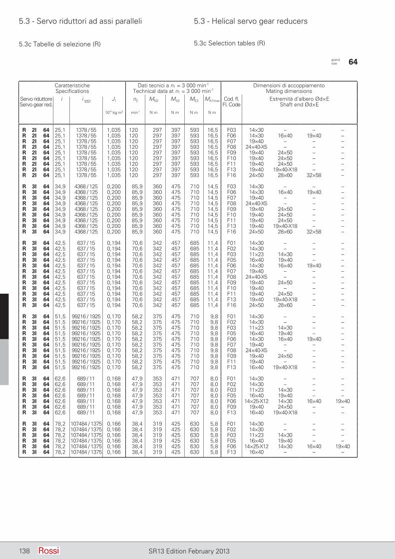
5.3 - Servo riduttori ad assi paralleli 5.3 - Helical servo gear reducers
138 SR13 Edition February 2013
5.3c Tabelle di selezione (R) 5.3c Selection tables (R)
CaratteristicheSpecifications
Dati tecnici a n1 = 3 000 min-1
Technical data at n1 = 3 000 min-1Dimensioni di accoppiamento
Mating dimensionsServo riduttoreServo gear red.
i J1 n2 MN2 MA2 ME2 MA1max Cod. fl. Fl. Code
Estremità d’albero Ød×EShaft end Ød×E
10-4 kg m2 min-1 N m N m N m N m
R 2I 64 25,1 1378 / 55 1,035 120 297 397 593 16,5 F03 14×30 – – –R 2I 64 25,1 1378 / 55 1,035 120 297 397 593 16,5 F06 14×30 16×40 19×40 –R 2I 64 25,1 1378 / 55 1,035 120 297 397 593 16,5 F07 19×40 – – –R 2I 64 25,1 1378 / 55 1,035 120 297 397 593 16,5 F08 24×40-X5 – – –R 2I 64 25,1 1378 / 55 1,035 120 297 397 593 16,5 F09 19×40 24×50 – –R 2I 64 25,1 1378 / 55 1,035 120 297 397 593 16,5 F10 19×40 24×50 – –R 2I 64 25,1 1378 / 55 1,035 120 297 397 593 16,5 F11 19×40 24×50 – –R 2I 64 25,1 1378 / 55 1,035 120 297 397 593 16,5 F13 19×40 19×40-X18 – –R 2I 64 25,1 1378 / 55 1,035 120 297 397 593 16,5 F16 24×50 28×60 32×58 –
R 3I 64 34,9 4368 / 125 0,200 85,9 360 475 710 14,5 F03 14×30 – – –R 3I 64 34,9 4368 / 125 0,200 85,9 360 475 710 14,5 F06 14×30 16×40 19×40 –R 3I 64 34,9 4368 / 125 0,200 85,9 360 475 710 14,5 F07 19×40 – – –R 3I 64 34,9 4368 / 125 0,200 85,9 360 475 710 14,5 F08 24×40-X5 – – –R 3I 64 34,9 4368 / 125 0,200 85,9 360 475 710 14,5 F09 19×40 24×50 – –R 3I 64 34,9 4368 / 125 0,200 85,9 360 475 710 14,5 F10 19×40 24×50 – –R 3I 64 34,9 4368 / 125 0,200 85,9 360 475 710 14,5 F11 19×40 24×50 – –R 3I 64 34,9 4368 / 125 0,200 85,9 360 475 710 14,5 F13 19×40 19×40-X18 – –R 3I 64 34,9 4368 / 125 0,200 85,9 360 475 710 14,5 F16 24×50 28×60 32×58 –
R 3I 64 42,5 637 / 15 0,194 70,6 342 457 685 11,4 F01 14×30 – – –R 3I 64 42,5 637 / 15 0,194 70,6 342 457 685 11,4 F02 14×30 – – –R 3I 64 42,5 637 / 15 0,194 70,6 342 457 685 11,4 F03 11×23 14×30 – –R 3I 64 42,5 637 / 15 0,194 70,6 342 457 685 11,4 F05 16×40 19×40 – –R 3I 64 42,5 637 / 15 0,194 70,6 342 457 685 11,4 F06 14×30 16×40 19×40 –R 3I 64 42,5 637 / 15 0,194 70,6 342 457 685 11,4 F07 19×40 – – –R 3I 64 42,5 637 / 15 0,194 70,6 342 457 685 11,4 F08 24×40-X5 – – –R 3I 64 42,5 637 / 15 0,194 70,6 342 457 685 11,4 F09 19×40 24×50 – –R 3I 64 42,5 637 / 15 0,194 70,6 342 457 685 11,4 F10 19×40 – – –R 3I 64 42,5 637 / 15 0,194 70,6 342 457 685 11,4 F11 19×40 24×50 – –R 3I 64 42,5 637 / 15 0,194 70,6 342 457 685 11,4 F13 19×40 19×40-X18 – –R 3I 64 42,5 637 / 15 0,194 70,6 342 457 685 11,4 F16 24×50 28×60 – –
R 3I 64 51,5 99216 / 1925 0,170 58,2 375 475 710 9,8 F01 14×30 – – –R 3I 64 51,5 99216 / 1925 0,170 58,2 375 475 710 9,8 F02 14×30 – – –R 3I 64 51,5 99216 / 1925 0,170 58,2 375 475 710 9,8 F03 11×23 14×30 – –R 3I 64 51,5 99216 / 1925 0,170 58,2 375 475 710 9,8 F05 16×40 19×40 – –R 3I 64 51,5 99216 / 1925 0,170 58,2 375 475 710 9,8 F06 14×30 16×40 19×40 –R 3I 64 51,5 99216 / 1925 0,170 58,2 375 475 710 9,8 F07 19×40 – – –R 3I 64 51,5 99216 / 1925 0,170 58,2 375 475 710 9,8 F08 24×40-X5 – – –R 3I 64 51,5 99216 / 1925 0,170 58,2 375 475 710 9,8 F09 19×40 24×50 – –R 3I 64 51,5 99216 / 1925 0,170 58,2 375 475 710 9,8 F11 19×40 – – –R 3I 64 51,5 99216 / 1925 0,170 58,2 375 475 710 9,8 F13 16×40 19×40-X18 – –
R 3I 64 62,6 689 / 11 0,168 47,9 353 471 707 8,0 F01 14×30 – – –R 3I 64 62,6 689 / 11 0,168 47,9 353 471 707 8,0 F02 14×30 – – –R 3I 64 62,6 689 / 11 0,168 47,9 353 471 707 8,0 F03 11×23 14×30 – –R 3I 64 62,6 689 / 11 0,168 47,9 353 471 707 8,0 F05 16×40 19×40 – –R 3I 64 62,6 689 / 11 0,168 47,9 353 471 707 8,0 F06 14×25-X12 14×30 16×40 19×40R 3I 64 62,6 689 / 11 0,168 47,9 353 471 707 8,0 F09 19×40 24×50 – –R 3I 64 62,6 689 / 11 0,168 47,9 353 471 707 8,0 F13 16×40 19×40-X18 – –
R 3I 64 78,2 107484 / 1375 0,166 38,4 319 425 630 5,8 F01 14×30 – – –R 3I 64 78,2 107484 / 1375 0,166 38,4 319 425 630 5,8 F02 14×30 – – –R 3I 64 78,2 107484 / 1375 0,166 38,4 319 425 630 5,8 F03 11×23 14×30 – –R 3I 64 78,2 107484 / 1375 0,166 38,4 319 425 630 5,8 F05 16×40 19×40 – –R 3I 64 78,2 107484 / 1375 0,166 38,4 319 425 630 5,8 F06 14×25-X12 14×30 16×40 19×40R 3I 64 78,2 107484 / 1375 0,166 38,4 319 425 630 5,8 F13 16×40 – – –
i esattoexact
grand. size 64
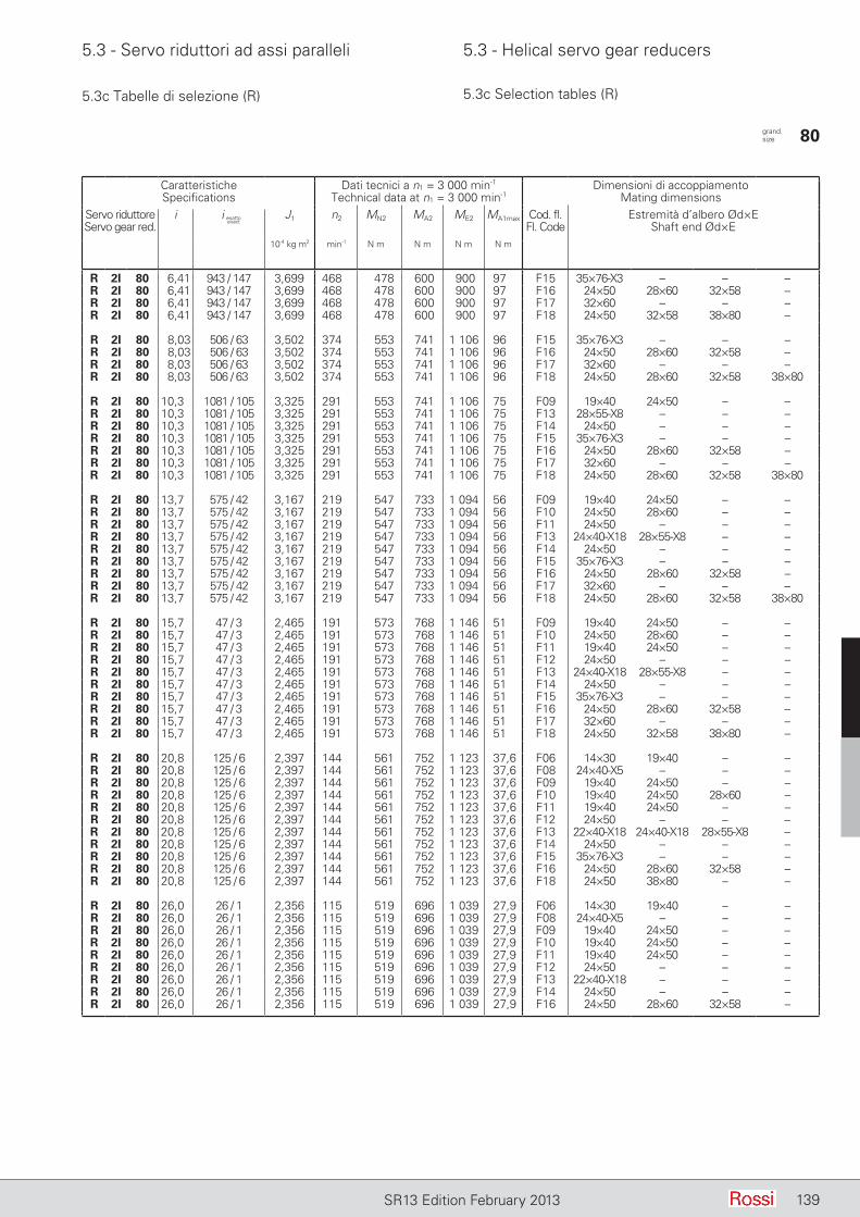
5.3 - Servo riduttori ad assi paralleli 5.3 - Helical servo gear reducers
139SR13 Edition February 2013
5.3c Tabelle di selezione (R) 5.3c Selection tables (R)
CaratteristicheSpecifications
Dati tecnici a n1 = 3 000 min-1
Technical data at n1 = 3 000 min-1Dimensioni di accoppiamento
Mating dimensionsServo riduttoreServo gear red.
i J1 n2 MN2 MA2 ME2 MA1max Cod. fl. Fl. Code
Estremità d’albero Ød×EShaft end Ød×E
10-4 kg m2 min-1 N m N m N m N m
R 2I 80 6,41 943 / 147 3,699 468 478 600 900 97 F15 35×76-X3 – – –R 2I 80 6,41 943 / 147 3,699 468 478 600 900 97 F16 24×50 28×60 32×58 –R 2I 80 6,41 943 / 147 3,699 468 478 600 900 97 F17 32×60 – – –R 2I 80 6,41 943 / 147 3,699 468 478 600 900 97 F18 24×50 32×58 38×80 –
R 2I 80 8,03 506 / 63 3,502 374 553 741 1 106 96 F15 35×76-X3 – – –R 2I 80 8,03 506 / 63 3,502 374 553 741 1 106 96 F16 24×50 28×60 32×58 –R 2I 80 8,03 506 / 63 3,502 374 553 741 1 106 96 F17 32×60 – – –R 2I 80 8,03 506 / 63 3,502 374 553 741 1 106 96 F18 24×50 28×60 32×58 38×80
R 2I 80 10,3 1081 / 105 3,325 291 553 741 1 106 75 F09 19×40 24×50 – –R 2I 80 10,3 1081 / 105 3,325 291 553 741 1 106 75 F13 28×55-X8 – – –R 2I 80 10,3 1081 / 105 3,325 291 553 741 1 106 75 F14 24×50 – – –R 2I 80 10,3 1081 / 105 3,325 291 553 741 1 106 75 F15 35×76-X3 – – –R 2I 80 10,3 1081 / 105 3,325 291 553 741 1 106 75 F16 24×50 28×60 32×58 –R 2I 80 10,3 1081 / 105 3,325 291 553 741 1 106 75 F17 32×60 – – –R 2I 80 10,3 1081 / 105 3,325 291 553 741 1 106 75 F18 24×50 28×60 32×58 38×80
R 2I 80 13,7 575 / 42 3,167 219 547 733 1 094 56 F09 19×40 24×50 – –R 2I 80 13,7 575 / 42 3,167 219 547 733 1 094 56 F10 24×50 28×60 – –R 2I 80 13,7 575 / 42 3,167 219 547 733 1 094 56 F11 24×50 – – –R 2I 80 13,7 575 / 42 3,167 219 547 733 1 094 56 F13 24×40-X18 28×55-X8 – –R 2I 80 13,7 575 / 42 3,167 219 547 733 1 094 56 F14 24×50 – – –R 2I 80 13,7 575 / 42 3,167 219 547 733 1 094 56 F15 35×76-X3 – – –R 2I 80 13,7 575 / 42 3,167 219 547 733 1 094 56 F16 24×50 28×60 32×58 –R 2I 80 13,7 575 / 42 3,167 219 547 733 1 094 56 F17 32×60 – – –R 2I 80 13,7 575 / 42 3,167 219 547 733 1 094 56 F18 24×50 28×60 32×58 38×80
R 2I 80 15,7 47 / 3 2,465 191 573 768 1 146 51 F09 19×40 24×50 – –R 2I 80 15,7 47 / 3 2,465 191 573 768 1 146 51 F10 24×50 28×60 – –R 2I 80 15,7 47 / 3 2,465 191 573 768 1 146 51 F11 19×40 24×50 – –R 2I 80 15,7 47 / 3 2,465 191 573 768 1 146 51 F12 24×50 – – –R 2I 80 15,7 47 / 3 2,465 191 573 768 1 146 51 F13 24×40-X18 28×55-X8 – –R 2I 80 15,7 47 / 3 2,465 191 573 768 1 146 51 F14 24×50 – – –R 2I 80 15,7 47 / 3 2,465 191 573 768 1 146 51 F15 35×76-X3 – – –R 2I 80 15,7 47 / 3 2,465 191 573 768 1 146 51 F16 24×50 28×60 32×58 –R 2I 80 15,7 47 / 3 2,465 191 573 768 1 146 51 F17 32×60 – – –R 2I 80 15,7 47 / 3 2,465 191 573 768 1 146 51 F18 24×50 32×58 38×80 –
R 2I 80 20,8 125 / 6 2,397 144 561 752 1 123 37,6 F06 14×30 19×40 – –R 2I 80 20,8 125 / 6 2,397 144 561 752 1 123 37,6 F08 24×40-X5 – – –R 2I 80 20,8 125 / 6 2,397 144 561 752 1 123 37,6 F09 19×40 24×50 – –R 2I 80 20,8 125 / 6 2,397 144 561 752 1 123 37,6 F10 19×40 24×50 28×60 –R 2I 80 20,8 125 / 6 2,397 144 561 752 1 123 37,6 F11 19×40 24×50 – –R 2I 80 20,8 125 / 6 2,397 144 561 752 1 123 37,6 F12 24×50 – – –R 2I 80 20,8 125 / 6 2,397 144 561 752 1 123 37,6 F13 22×40-X18 24×40-X18 28×55-X8 –R 2I 80 20,8 125 / 6 2,397 144 561 752 1 123 37,6 F14 24×50 – – –R 2I 80 20,8 125 / 6 2,397 144 561 752 1 123 37,6 F15 35×76-X3 – – –R 2I 80 20,8 125 / 6 2,397 144 561 752 1 123 37,6 F16 24×50 28×60 32×58 –R 2I 80 20,8 125 / 6 2,397 144 561 752 1 123 37,6 F18 24×50 38×80 – –
R 2I 80 26,0 26 / 1 2,356 115 519 696 1 039 27,9 F06 14×30 19×40 – –R 2I 80 26,0 26 / 1 2,356 115 519 696 1 039 27,9 F08 24×40-X5 – – –R 2I 80 26,0 26 / 1 2,356 115 519 696 1 039 27,9 F09 19×40 24×50 – –R 2I 80 26,0 26 / 1 2,356 115 519 696 1 039 27,9 F10 19×40 24×50 – –R 2I 80 26,0 26 / 1 2,356 115 519 696 1 039 27,9 F11 19×40 24×50 – –R 2I 80 26,0 26 / 1 2,356 115 519 696 1 039 27,9 F12 24×50 – – –R 2I 80 26,0 26 / 1 2,356 115 519 696 1 039 27,9 F13 22×40-X18 – – –R 2I 80 26,0 26 / 1 2,356 115 519 696 1 039 27,9 F14 24×50 – – –R 2I 80 26,0 26 / 1 2,356 115 519 696 1 039 27,9 F16 24×50 28×60 32×58 –
i esattoexact
grand. size 80
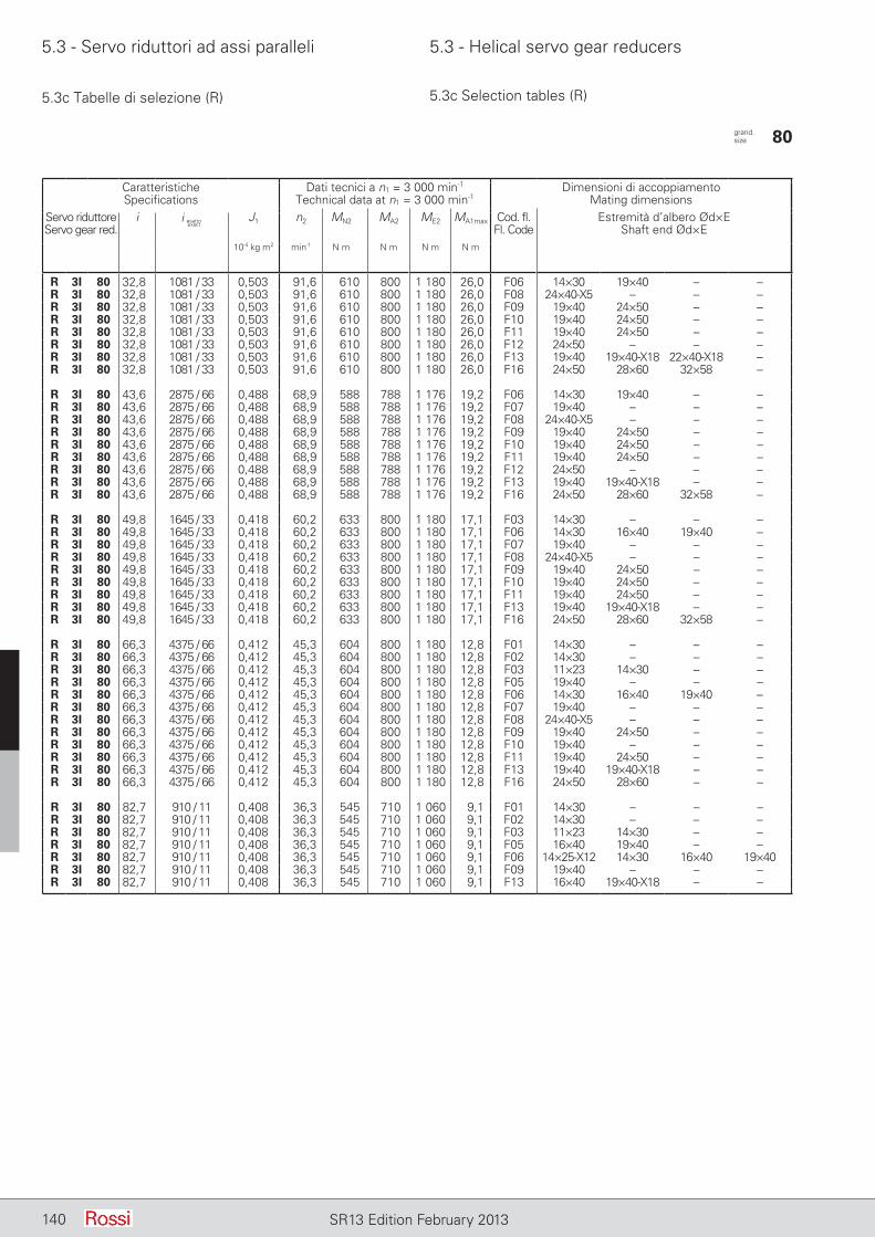
5.3 - Servo riduttori ad assi paralleli 5.3 - Helical servo gear reducers
140 SR13 Edition February 2013
CaratteristicheSpecifications
Dati tecnici a n1 = 3 000 min-1
Technical data at n1 = 3 000 min-1Dimensioni di accoppiamento
Mating dimensionsServo riduttoreServo gear red.
i J1 n2 MN2 MA2 ME2 MA1max Cod. fl. Fl. Code
Estremità d’albero Ød×EShaft end Ød×E
10-4 kg m2 min-1 N m N m N m N m
R 3I 80 32,8 1081 / 33 0,503 91,6 610 800 1 180 26,0 F06 14×30 19×40 – –R 3I 80 32,8 1081 / 33 0,503 91,6 610 800 1 180 26,0 F08 24×40-X5 – – –R 3I 80 32,8 1081 / 33 0,503 91,6 610 800 1 180 26,0 F09 19×40 24×50 – –R 3I 80 32,8 1081 / 33 0,503 91,6 610 800 1 180 26,0 F10 19×40 24×50 – –R 3I 80 32,8 1081 / 33 0,503 91,6 610 800 1 180 26,0 F11 19×40 24×50 – –R 3I 80 32,8 1081 / 33 0,503 91,6 610 800 1 180 26,0 F12 24×50 – – –R 3I 80 32,8 1081 / 33 0,503 91,6 610 800 1 180 26,0 F13 19×40 19×40-X18 22×40-X18 –R 3I 80 32,8 1081 / 33 0,503 91,6 610 800 1 180 26,0 F16 24×50 28×60 32×58 –
R 3I 80 43,6 2875 / 66 0,488 68,9 588 788 1 176 19,2 F06 14×30 19×40 – –R 3I 80 43,6 2875 / 66 0,488 68,9 588 788 1 176 19,2 F07 19×40 – – –R 3I 80 43,6 2875 / 66 0,488 68,9 588 788 1 176 19,2 F08 24×40-X5 – – –R 3I 80 43,6 2875 / 66 0,488 68,9 588 788 1 176 19,2 F09 19×40 24×50 – –R 3I 80 43,6 2875 / 66 0,488 68,9 588 788 1 176 19,2 F10 19×40 24×50 – –R 3I 80 43,6 2875 / 66 0,488 68,9 588 788 1 176 19,2 F11 19×40 24×50 – –R 3I 80 43,6 2875 / 66 0,488 68,9 588 788 1 176 19,2 F12 24×50 – – –R 3I 80 43,6 2875 / 66 0,488 68,9 588 788 1 176 19,2 F13 19×40 19×40-X18 – –R 3I 80 43,6 2875 / 66 0,488 68,9 588 788 1 176 19,2 F16 24×50 28×60 32×58 –
R 3I 80 49,8 1645 / 33 0,418 60,2 633 800 1 180 17,1 F03 14×30 – – –R 3I 80 49,8 1645 / 33 0,418 60,2 633 800 1 180 17,1 F06 14×30 16×40 19×40 –R 3I 80 49,8 1645 / 33 0,418 60,2 633 800 1 180 17,1 F07 19×40 – – –R 3I 80 49,8 1645 / 33 0,418 60,2 633 800 1 180 17,1 F08 24×40-X5 – – –R 3I 80 49,8 1645 / 33 0,418 60,2 633 800 1 180 17,1 F09 19×40 24×50 – –R 3I 80 49,8 1645 / 33 0,418 60,2 633 800 1 180 17,1 F10 19×40 24×50 – –R 3I 80 49,8 1645 / 33 0,418 60,2 633 800 1 180 17,1 F11 19×40 24×50 – –R 3I 80 49,8 1645 / 33 0,418 60,2 633 800 1 180 17,1 F13 19×40 19×40-X18 – –R 3I 80 49,8 1645 / 33 0,418 60,2 633 800 1 180 17,1 F16 24×50 28×60 32×58 –
R 3I 80 66,3 4375 / 66 0,412 45,3 604 800 1 180 12,8 F01 14×30 – – –R 3I 80 66,3 4375 / 66 0,412 45,3 604 800 1 180 12,8 F02 14×30 – – –R 3I 80 66,3 4375 / 66 0,412 45,3 604 800 1 180 12,8 F03 11×23 14×30 – –R 3I 80 66,3 4375 / 66 0,412 45,3 604 800 1 180 12,8 F05 19×40 – – –R 3I 80 66,3 4375 / 66 0,412 45,3 604 800 1 180 12,8 F06 14×30 16×40 19×40 –R 3I 80 66,3 4375 / 66 0,412 45,3 604 800 1 180 12,8 F07 19×40 – – –R 3I 80 66,3 4375 / 66 0,412 45,3 604 800 1 180 12,8 F08 24×40-X5 – – –R 3I 80 66,3 4375 / 66 0,412 45,3 604 800 1 180 12,8 F09 19×40 24×50 – –R 3I 80 66,3 4375 / 66 0,412 45,3 604 800 1 180 12,8 F10 19×40 – – –R 3I 80 66,3 4375 / 66 0,412 45,3 604 800 1 180 12,8 F11 19×40 24×50 – –R 3I 80 66,3 4375 / 66 0,412 45,3 604 800 1 180 12,8 F13 19×40 19×40-X18 – –R 3I 80 66,3 4375 / 66 0,412 45,3 604 800 1 180 12,8 F16 24×50 28×60 – –
R 3I 80 82,7 910 / 11 0,408 36,3 545 710 1 060 9,1 F01 14×30 – – –R 3I 80 82,7 910 / 11 0,408 36,3 545 710 1 060 9,1 F02 14×30 – – –R 3I 80 82,7 910 / 11 0,408 36,3 545 710 1 060 9,1 F03 11×23 14×30 – –R 3I 80 82,7 910 / 11 0,408 36,3 545 710 1 060 9,1 F05 16×40 19×40 – –R 3I 80 82,7 910 / 11 0,408 36,3 545 710 1 060 9,1 F06 14×25-X12 14×30 16×40 19×40R 3I 80 82,7 910 / 11 0,408 36,3 545 710 1 060 9,1 F09 19×40 – – –R 3I 80 82,7 910 / 11 0,408 36,3 545 710 1 060 9,1 F13 16×40 19×40-X18 – –
5.3c Tabelle di selezione (R) 5.3c Selection tables (R)
i esattoexact
grand. size 80
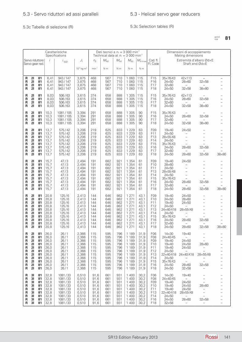
5.3 - Servo riduttori ad assi paralleli 5.3 - Helical servo gear reducers
141SR13 Edition February 2013
5.3c Tabelle di selezione (R) 5.3c Selection tables (R)
CaratteristicheSpecifications
Dati tecnici a n1 = 3 000 min-1
Technical data at n1 = 3 000 min-1Dimensioni di accoppiamento
Mating dimensionsServo riduttoreServo gear red.
i J1 n2 MN2 MA2 ME2 MA1max Cod. fl. Fl. Code
Estremità d’albero Ød×EShaft end Ød×E
10-4 kg m2 min-1 N m N m N m N m
R 2I 81 6,41 943 / 147 3,875 468 567 710 1 060 115 F15 35×76-X3 42×113 – –R 2I 81 6,41 943 / 147 3,875 468 567 710 1 060 115 F16 24×50 28×60 32×58 –R 2I 81 6,41 943 / 147 3,875 468 567 710 1 060 115 F17 32×60 – – –R 2I 81 6,41 943 / 147 3,875 468 567 710 1 060 115 F18 24×50 32×58 38×80 –
R 2I 81 8,03 506 / 63 3,615 374 658 888 1 305 115 F15 35×76-X3 42×113 – –R 2I 81 8,03 506 / 63 3,615 374 658 888 1 305 115 F16 24×50 28×60 32×58 –R 2I 81 8,03 506 / 63 3,615 374 658 888 1 305 115 F17 32×60 – – –R 2I 81 8,03 506 / 63 3,615 374 658 888 1 305 115 F18 24×50 32×58 38×80 –
R 2I 81 10,3 1081 / 105 3,394 291 658 888 1 305 90 F15 35×76-X3 – – –R 2I 81 10,3 1081 / 105 3,394 291 658 888 1 305 90 F16 24×50 28×60 32×58 –R 2I 81 10,3 1081 / 105 3,394 291 658 888 1 305 90 F17 32×60 – – –R 2I 81 10,3 1081 / 105 3,394 291 658 888 1 305 90 F18 24×50 32×58 38×80 –
R 2I 81 13,7 575 / 42 3,206 219 625 833 1 229 63 F09 19×40 24×50 – –R 2I 81 13,7 575 / 42 3,206 219 625 833 1 229 63 F11 24×50 – – –R 2I 81 13,7 575 / 42 3,206 219 625 833 1 229 63 F13 28×55-X8 – – –R 2I 81 13,7 575 / 42 3,206 219 625 833 1 229 63 F14 24×50 – – –R 2I 81 13,7 575 / 42 3,206 219 625 833 1 229 63 F15 35×76-X3 – – –R 2I 81 13,7 575 / 42 3,206 219 625 833 1 229 63 F16 24×50 28×60 32×58 –R 2I 81 13,7 575 / 42 3,206 219 625 833 1 229 63 F17 32×60 – – –R 2I 81 13,7 575 / 42 3,206 219 625 833 1 229 63 F18 24×50 28×60 32×58 38×80
R 2I 81 15,7 47 / 3 2,494 191 682 921 1 354 61 F09 19×40 24×50 – –R 2I 81 15,7 47 / 3 2,494 191 682 921 1 354 61 F10 28×60 – – –R 2I 81 15,7 47 / 3 2,494 191 682 921 1 354 61 F11 24×50 – – –R 2I 81 15,7 47 / 3 2,494 191 682 921 1 354 61 F13 28×55-X8 – – –R 2I 81 15,7 47 / 3 2,494 191 682 921 1 354 61 F14 24×50 – – –R 2I 81 15,7 47 / 3 2,494 191 682 921 1 354 61 F15 35×76-X3 – – –R 2I 81 15,7 47 / 3 2,494 191 682 921 1 354 61 F16 24×50 28×60 32×58 –R 2I 81 15,7 47 / 3 2,494 191 682 921 1 354 61 F17 32×60 – – –R 2I 81 15,7 47 / 3 2,494 191 682 921 1 354 61 F18 24×50 28×60 32×58 38×80
R 2I 81 20,8 125 / 6 2,413 144 646 862 1 271 43,1 F09 19×40 24×50 – –R 2I 81 20,8 125 / 6 2,413 144 646 862 1 271 43,1 F10 24×50 28×60 – –R 2I 81 20,8 125 / 6 2,413 144 646 862 1 271 43,1 F11 19×40 24×50 – –R 2I 81 20,8 125 / 6 2,413 144 646 862 1 271 43,1 F12 24×50 – – –R 2I 81 20,8 125 / 6 2,413 144 646 862 1 271 43,1 F13 24×40-X18 28×55-X8 – –R 2I 81 20,8 125 / 6 2,413 144 646 862 1 271 43,1 F14 24×50 – – –R 2I 81 20,8 125 / 6 2,413 144 646 862 1 271 43,1 F15 35×76-X3 – – –R 2I 81 20,8 125 / 6 2,413 144 646 862 1 271 43,1 F16 24×50 28×60 32×58 –R 2I 81 20,8 125 / 6 2,413 144 646 862 1 271 43,1 F17 32×60 – – –R 2I 81 20,8 125 / 6 2,413 144 646 862 1 271 43,1 F18 24×50 28×60 32×58 38×80
R 2I 81 26,0 26 / 1 2,366 115 595 796 1 189 31,9 F06 14×30 19×40 – –R 2I 81 26,0 26 / 1 2,366 115 595 796 1 189 31,9 F08 24×40-X5 – – –R 2I 81 26,0 26 / 1 2,366 115 595 796 1 189 31,9 F09 19×40 24×50 – –R 2I 81 26,0 26 / 1 2,366 115 595 796 1 189 31,9 F10 19×40 24×50 28×60 –R 2I 81 26,0 26 / 1 2,366 115 595 796 1 189 31,9 F11 19×40 24×50 – –R 2I 81 26,0 26 / 1 2,366 115 595 796 1 189 31,9 F12 24×50 – – –R 2I 81 26,0 26 / 1 2,366 115 595 796 1 189 31,9 F13 22×40-X18 24×40-X18 28×55-X8 –R 2I 81 26,0 26 / 1 2,366 115 595 796 1 189 31,9 F14 24×50 – – –R 2I 81 26,0 26 / 1 2,366 115 595 796 1 189 31,9 F15 35×76-X3 – – –R 2I 81 26,0 26 / 1 2,366 115 595 796 1 189 31,9 F16 24×50 28×60 32×58 –R 2I 81 26,0 26 / 1 2,366 115 595 796 1 189 31,9 F18 24×50 32×58 – –
R 3I 81 32,8 1081 / 33 0,510 91,6 661 931 1 400 30,2 F06 14×30 19×40 – –R 3I 81 32,8 1081 / 33 0,510 91,6 661 931 1 400 30,2 F08 24×40-X5 – – –R 3I 81 32,8 1081 / 33 0,510 91,6 661 931 1 400 30,2 F09 19×40 24×50 – –R 3I 81 32,8 1081 / 33 0,510 91,6 661 931 1 400 30,2 F10 19×40 24×50 28×60 –R 3I 81 32,8 1081 / 33 0,510 91,6 661 931 1 400 30,2 F11 19×40 24×50 – –R 3I 81 32,8 1081 / 33 0,510 91,6 661 931 1 400 30,2 F13 22×40-X18 28×55-X8 – –R 3I 81 32,8 1081 / 33 0,510 91,6 661 931 1 400 30,2 F14 24×50 – – –R 3I 81 32,8 1081 / 33 0,510 91,6 661 931 1 400 30,2 F16 24×50 28×60 32×58 –R 3I 81 32,8 1081 / 33 0,510 91,6 661 931 1 400 30,2 F18 32×58 – – –
i esattoexact
grand. size 81
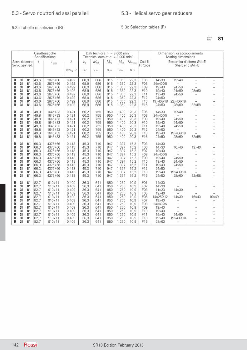
5.3 - Servo riduttori ad assi paralleli 5.3 - Helical servo gear reducers
142 SR13 Edition February 2013
5.3c Tabelle di selezione (R) 5.3c Selection tables (R)
CaratteristicheSpecifications
Dati tecnici a n1 = 3 000 min-1
Technical data at n1 = 3 000 min-1Dimensioni di accoppiamento
Mating dimensionsServo riduttoreServo gear red.
i J1 n2 MN2 MA2 ME2 MA1max Cod. fl. Fl. Code
Estremità d’albero Ød×EShaft end Ød×E
10-4 kg m2 min-1 N m N m N m N m
R 3I 81 43,6 2875 / 66 0,492 68,9 686 915 1 350 22,3 F06 14×30 19×40 – –R 3I 81 43,6 2875 / 66 0,492 68,9 686 915 1 350 22,3 F08 24×40-X5 – – –R 3I 81 43,6 2875 / 66 0,492 68,9 686 915 1 350 22,3 F09 19×40 24×50 – –R 3I 81 43,6 2875 / 66 0,492 68,9 686 915 1 350 22,3 F10 19×40 24×50 28×60 –R 3I 81 43,6 2875 / 66 0,492 68,9 686 915 1 350 22,3 F11 19×40 24×50 – –R 3I 81 43,6 2875 / 66 0,492 68,9 686 915 1 350 22,3 F12 24×50 – – –R 3I 81 43,6 2875 / 66 0,492 68,9 686 915 1 350 22,3 F13 19×40-X18 22×40-X18 – –R 3I 81 43,6 2875 / 66 0,492 68,9 686 915 1 350 22,3 F16 24×50 28×60 32×58 –
R 3I 81 49,8 1645 / 33 0,421 60,2 755 950 1 400 20,3 F06 14×30 19×40 – –R 3I 81 49,8 1645 / 33 0,421 60,2 755 950 1 400 20,3 F08 24×40-X5 – – –R 3I 81 49,8 1645 / 33 0,421 60,2 755 950 1 400 20,3 F09 19×40 24×50 – –R 3I 81 49,8 1645 / 33 0,421 60,2 755 950 1 400 20,3 F10 19×40 24×50 – –R 3I 81 49,8 1645 / 33 0,421 60,2 755 950 1 400 20,3 F11 19×40 24×50 – –R 3I 81 49,8 1645 / 33 0,421 60,2 755 950 1 400 20,3 F12 24×50 – – –R 3I 81 49,8 1645 / 33 0,421 60,2 755 950 1 400 20,3 F13 19×40 19×40-X18 – –R 3I 81 49,8 1645 / 33 0,421 60,2 755 950 1 400 20,3 F16 24×50 28×60 32×58 –
R 3I 81 66,3 4375 / 66 0,413 45,3 710 947 1 397 15,2 F03 14×30 – – –R 3I 81 66,3 4375 / 66 0,413 45,3 710 947 1 397 15,2 F06 14×30 16×40 19×40 –R 3I 81 66,3 4375 / 66 0,413 45,3 710 947 1 397 15,2 F07 19×40 – – –R 3I 81 66,3 4375 / 66 0,413 45,3 710 947 1 397 15,2 F08 24×40-X5 – – –R 3I 81 66,3 4375 / 66 0,413 45,3 710 947 1 397 15,2 F09 19×40 24×50 – –R 3I 81 66,3 4375 / 66 0,413 45,3 710 947 1 397 15,2 F10 19×40 24×50 – –R 3I 81 66,3 4375 / 66 0,413 45,3 710 947 1 397 15,2 F11 19×40 24×50 – –R 3I 81 66,3 4375 / 66 0,413 45,3 710 947 1 397 15,2 F12 24×50 – – –R 3I 81 66,3 4375 / 66 0,413 45,3 710 947 1 397 15,2 F13 19×40 19×40-X18 – –R 3I 81 66,3 4375 / 66 0,413 45,3 710 947 1 397 15,2 F16 24×50 28×60 32×58 –
R 3I 81 82,7 910 / 11 0,409 36,3 641 850 1 250 10,9 F01 14×30 – – –R 3I 81 82,7 910 / 11 0,409 36,3 641 850 1 250 10,9 F02 14×30 – – –R 3I 81 82,7 910 / 11 0,409 36,3 641 850 1 250 10,9 F03 11×23 14×30 – –R 3I 81 82,7 910 / 11 0,409 36,3 641 850 1 250 10,9 F05 19×40 – – –R 3I 81 82,7 910 / 11 0,409 36,3 641 850 1 250 10,9 F06 14×25-X12 14×30 16×40 19×40R 3I 81 82,7 910 / 11 0,409 36,3 641 850 1 250 10,9 F07 19×40 – – –R 3I 81 82,7 910 / 11 0,409 36,3 641 850 1 250 10,9 F08 24×40-X5 – – –R 3I 81 82,7 910 / 11 0,409 36,3 641 850 1 250 10,9 F09 19×40 – – –R 3I 81 82,7 910 / 11 0,409 36,3 641 850 1 250 10,9 F10 19×40 – – –R 3I 81 82,7 910 / 11 0,409 36,3 641 850 1 250 10,9 F11 19×40 24×50 – –R 3I 81 82,7 910 / 11 0,409 36,3 641 850 1 250 10,9 F13 19×40 19×40-X18 – –R 3I 81 82,7 910 / 11 0,409 36,3 641 850 1 250 10,9 F16 28×60 – – –
i esattoexact
grand. size 81
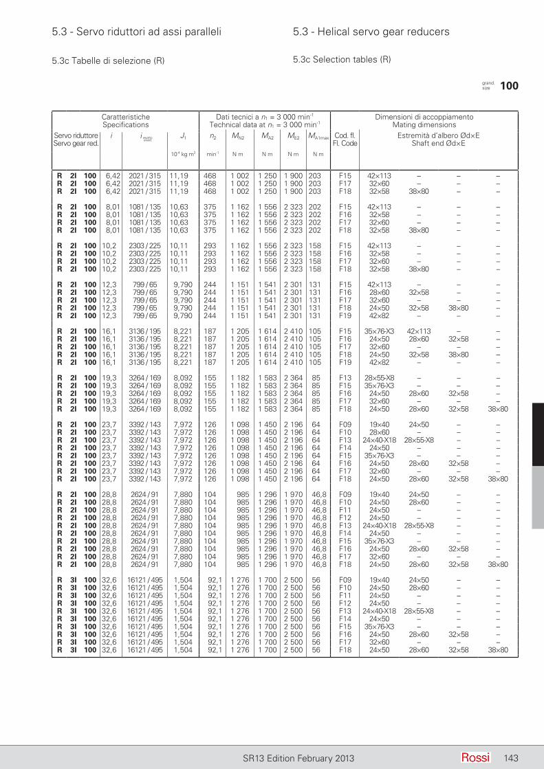
5.3 - Servo riduttori ad assi paralleli 5.3 - Helical servo gear reducers
143SR13 Edition February 2013
5.3c Tabelle di selezione (R) 5.3c Selection tables (R)
CaratteristicheSpecifications
Dati tecnici a n1 = 3 000 min-1
Technical data at n1 = 3 000 min-1Dimensioni di accoppiamento
Mating dimensionsServo riduttoreServo gear red.
i J1 n2 MN2 MA2 ME2 MA1max Cod. fl. Fl. Code
Estremità d’albero Ød×EShaft end Ød×E
10-4 kg m2 min-1 N m N m N m N m
R 2I 100 6,42 2021 / 315 11,19 468 1 002 1 250 1 900 203 F15 42×113 – – –R 2I 100 6,42 2021 / 315 11,19 468 1 002 1 250 1 900 203 F17 32×60 – – –R 2I 100 6,42 2021 / 315 11,19 468 1 002 1 250 1 900 203 F18 32×58 38×80 – –
R 2I 100 8,01 1081 / 135 10,63 375 1 162 1 556 2 323 202 F15 42×113 – – –R 2I 100 8,01 1081 / 135 10,63 375 1 162 1 556 2 323 202 F16 32×58 – – –R 2I 100 8,01 1081 / 135 10,63 375 1 162 1 556 2 323 202 F17 32×60 – – –R 2I 100 8,01 1081 / 135 10,63 375 1 162 1 556 2 323 202 F18 32×58 38×80 – –
R 2I 100 10,2 2303 / 225 10,11 293 1 162 1 556 2 323 158 F15 42×113 – – –R 2I 100 10,2 2303 / 225 10,11 293 1 162 1 556 2 323 158 F16 32×58 – – –R 2I 100 10,2 2303 / 225 10,11 293 1 162 1 556 2 323 158 F17 32×60 – – –R 2I 100 10,2 2303 / 225 10,11 293 1 162 1 556 2 323 158 F18 32×58 38×80 – –
R 2I 100 12,3 799 / 65 9,790 244 1 151 1 541 2 301 131 F15 42×113 – – –R 2I 100 12,3 799 / 65 9,790 244 1 151 1 541 2 301 131 F16 28×60 32×58 – –R 2I 100 12,3 799 / 65 9,790 244 1 151 1 541 2 301 131 F17 32×60 – – –R 2I 100 12,3 799 / 65 9,790 244 1 151 1 541 2 301 131 F18 24×50 32×58 38×80 –R 2I 100 12,3 799 / 65 9,790 244 1 151 1 541 2 301 131 F19 42×82 – – –
R 2I 100 16,1 3136 / 195 8,221 187 1 205 1 614 2 410 105 F15 35×76-X3 42×113 – –R 2I 100 16,1 3136 / 195 8,221 187 1 205 1 614 2 410 105 F16 24×50 28×60 32×58 –R 2I 100 16,1 3136 / 195 8,221 187 1 205 1 614 2 410 105 F17 32×60 – – –R 2I 100 16,1 3136 / 195 8,221 187 1 205 1 614 2 410 105 F18 24×50 32×58 38×80 –R 2I 100 16,1 3136 / 195 8,221 187 1 205 1 614 2 410 105 F19 42×82 – – –
R 2I 100 19,3 3264 / 169 8,092 155 1 182 1 583 2 364 85 F13 28×55-X8 – – –R 2I 100 19,3 3264 / 169 8,092 155 1 182 1 583 2 364 85 F15 35×76-X3 – – –R 2I 100 19,3 3264 / 169 8,092 155 1 182 1 583 2 364 85 F16 24×50 28×60 32×58 –R 2I 100 19,3 3264 / 169 8,092 155 1 182 1 583 2 364 85 F17 32×60 – – –R 2I 100 19,3 3264 / 169 8,092 155 1 182 1 583 2 364 85 F18 24×50 28×60 32×58 38×80
R 2I 100 23,7 3392 / 143 7,972 126 1 098 1 450 2 196 64 F09 19×40 24×50 – –R 2I 100 23,7 3392 / 143 7,972 126 1 098 1 450 2 196 64 F10 28×60 – – –R 2I 100 23,7 3392 / 143 7,972 126 1 098 1 450 2 196 64 F13 24×40-X18 28×55-X8 – –R 2I 100 23,7 3392 / 143 7,972 126 1 098 1 450 2 196 64 F14 24×50 – – –R 2I 100 23,7 3392 / 143 7,972 126 1 098 1 450 2 196 64 F15 35×76-X3 – – –R 2I 100 23,7 3392 / 143 7,972 126 1 098 1 450 2 196 64 F16 24×50 28×60 32×58 –R 2I 100 23,7 3392 / 143 7,972 126 1 098 1 450 2 196 64 F17 32×60 – – –R 2I 100 23,7 3392 / 143 7,972 126 1 098 1 450 2 196 64 F18 24×50 28×60 32×58 38×80
R 2I 100 28,8 2624 / 91 7,880 104 985 1 296 1 970 46,8 F09 19×40 24×50 – –R 2I 100 28,8 2624 / 91 7,880 104 985 1 296 1 970 46,8 F10 24×50 28×60 – –R 2I 100 28,8 2624 / 91 7,880 104 985 1 296 1 970 46,8 F11 24×50 – – –R 2I 100 28,8 2624 / 91 7,880 104 985 1 296 1 970 46,8 F12 24×50 – – –R 2I 100 28,8 2624 / 91 7,880 104 985 1 296 1 970 46,8 F13 24×40-X18 28×55-X8 – –R 2I 100 28,8 2624 / 91 7,880 104 985 1 296 1 970 46,8 F14 24×50 – – –R 2I 100 28,8 2624 / 91 7,880 104 985 1 296 1 970 46,8 F15 35×76-X3 – – –R 2I 100 28,8 2624 / 91 7,880 104 985 1 296 1 970 46,8 F16 24×50 28×60 32×58 –R 2I 100 28,8 2624 / 91 7,880 104 985 1 296 1 970 46,8 F17 32×60 – – –R 2I 100 28,8 2624 / 91 7,880 104 985 1 296 1 970 46,8 F18 24×50 28×60 32×58 38×80
R 3I 100 32,6 16121 / 495 1,504 92,1 1 276 1 700 2 500 56 F09 19×40 24×50 – –R 3I 100 32,6 16121 / 495 1,504 92,1 1 276 1 700 2 500 56 F10 24×50 28×60 – –R 3I 100 32,6 16121 / 495 1,504 92,1 1 276 1 700 2 500 56 F11 24×50 – – –R 3I 100 32,6 16121 / 495 1,504 92,1 1 276 1 700 2 500 56 F12 24×50 – – –R 3I 100 32,6 16121 / 495 1,504 92,1 1 276 1 700 2 500 56 F13 24×40-X18 28×55-X8 – –R 3I 100 32,6 16121 / 495 1,504 92,1 1 276 1 700 2 500 56 F14 24×50 – – –R 3I 100 32,6 16121 / 495 1,504 92,1 1 276 1 700 2 500 56 F15 35×76-X3 – – –R 3I 100 32,6 16121 / 495 1,504 92,1 1 276 1 700 2 500 56 F16 24×50 28×60 32×58 –R 3I 100 32,6 16121 / 495 1,504 92,1 1 276 1 700 2 500 56 F17 32×60 – – –R 3I 100 32,6 16121 / 495 1,504 92,1 1 276 1 700 2 500 56 F18 24×50 28×60 32×58 38×80
i esattoexact
grand. size 100
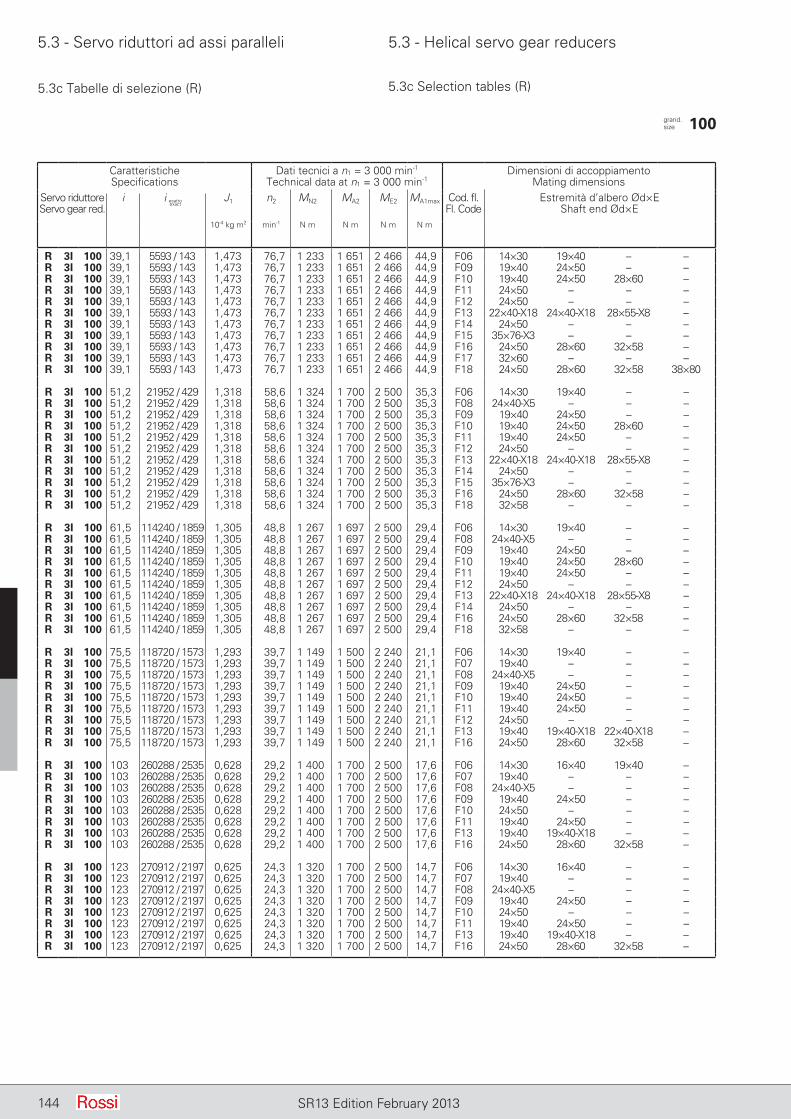
5.3 - Servo riduttori ad assi paralleli 5.3 - Helical servo gear reducers
144 SR13 Edition February 2013
5.3c Tabelle di selezione (R) 5.3c Selection tables (R)
CaratteristicheSpecifications
Dati tecnici a n1 = 3 000 min-1
Technical data at n1 = 3 000 min-1Dimensioni di accoppiamento
Mating dimensionsServo riduttoreServo gear red.
i J1 n2 MN2 MA2 ME2 MA1max Cod. fl. Fl. Code
Estremità d’albero Ød×EShaft end Ød×E
10-4 kg m2 min-1 N m N m N m N m
R 3I 100 39,1 5593 / 143 1,473 76,7 1 233 1 651 2 466 44,9 F06 14×30 19×40 – –R 3I 100 39,1 5593 / 143 1,473 76,7 1 233 1 651 2 466 44,9 F09 19×40 24×50 – –R 3I 100 39,1 5593 / 143 1,473 76,7 1 233 1 651 2 466 44,9 F10 19×40 24×50 28×60 –R 3I 100 39,1 5593 / 143 1,473 76,7 1 233 1 651 2 466 44,9 F11 24×50 – – –R 3I 100 39,1 5593 / 143 1,473 76,7 1 233 1 651 2 466 44,9 F12 24×50 – – –R 3I 100 39,1 5593 / 143 1,473 76,7 1 233 1 651 2 466 44,9 F13 22×40-X18 24×40-X18 28×55-X8 –R 3I 100 39,1 5593 / 143 1,473 76,7 1 233 1 651 2 466 44,9 F14 24×50 – – –R 3I 100 39,1 5593 / 143 1,473 76,7 1 233 1 651 2 466 44,9 F15 35×76-X3 – – –R 3I 100 39,1 5593 / 143 1,473 76,7 1 233 1 651 2 466 44,9 F16 24×50 28×60 32×58 –R 3I 100 39,1 5593 / 143 1,473 76,7 1 233 1 651 2 466 44,9 F17 32×60 – – –R 3I 100 39,1 5593 / 143 1,473 76,7 1 233 1 651 2 466 44,9 F18 24×50 28×60 32×58 38×80
R 3I 100 51,2 21952 / 429 1,318 58,6 1 324 1 700 2 500 35,3 F06 14×30 19×40 – –R 3I 100 51,2 21952 / 429 1,318 58,6 1 324 1 700 2 500 35,3 F08 24×40-X5 – – –R 3I 100 51,2 21952 / 429 1,318 58,6 1 324 1 700 2 500 35,3 F09 19×40 24×50 – –R 3I 100 51,2 21952 / 429 1,318 58,6 1 324 1 700 2 500 35,3 F10 19×40 24×50 28×60 –R 3I 100 51,2 21952 / 429 1,318 58,6 1 324 1 700 2 500 35,3 F11 19×40 24×50 – –R 3I 100 51,2 21952 / 429 1,318 58,6 1 324 1 700 2 500 35,3 F12 24×50 – – –R 3I 100 51,2 21952 / 429 1,318 58,6 1 324 1 700 2 500 35,3 F13 22×40-X18 24×40-X18 28×55-X8 –R 3I 100 51,2 21952 / 429 1,318 58,6 1 324 1 700 2 500 35,3 F14 24×50 – – –R 3I 100 51,2 21952 / 429 1,318 58,6 1 324 1 700 2 500 35,3 F15 35×76-X3 – – –R 3I 100 51,2 21952 / 429 1,318 58,6 1 324 1 700 2 500 35,3 F16 24×50 28×60 32×58 –R 3I 100 51,2 21952 / 429 1,318 58,6 1 324 1 700 2 500 35,3 F18 32×58 – – –
R 3I 100 61,5 114240 / 1859 1,305 48,8 1 267 1 697 2 500 29,4 F06 14×30 19×40 – –R 3I 100 61,5 114240 / 1859 1,305 48,8 1 267 1 697 2 500 29,4 F08 24×40-X5 – – –R 3I 100 61,5 114240 / 1859 1,305 48,8 1 267 1 697 2 500 29,4 F09 19×40 24×50 – –R 3I 100 61,5 114240 / 1859 1,305 48,8 1 267 1 697 2 500 29,4 F10 19×40 24×50 28×60 –R 3I 100 61,5 114240 / 1859 1,305 48,8 1 267 1 697 2 500 29,4 F11 19×40 24×50 – –R 3I 100 61,5 114240 / 1859 1,305 48,8 1 267 1 697 2 500 29,4 F12 24×50 – – –R 3I 100 61,5 114240 / 1859 1,305 48,8 1 267 1 697 2 500 29,4 F13 22×40-X18 24×40-X18 28×55-X8 –R 3I 100 61,5 114240 / 1859 1,305 48,8 1 267 1 697 2 500 29,4 F14 24×50 – – –R 3I 100 61,5 114240 / 1859 1,305 48,8 1 267 1 697 2 500 29,4 F16 24×50 28×60 32×58 –R 3I 100 61,5 114240 / 1859 1,305 48,8 1 267 1 697 2 500 29,4 F18 32×58 – – –
R 3I 100 75,5 118720 / 1573 1,293 39,7 1 149 1 500 2 240 21,1 F06 14×30 19×40 – –R 3I 100 75,5 118720 / 1573 1,293 39,7 1 149 1 500 2 240 21,1 F07 19×40 – – –R 3I 100 75,5 118720 / 1573 1,293 39,7 1 149 1 500 2 240 21,1 F08 24×40-X5 – – –R 3I 100 75,5 118720 / 1573 1,293 39,7 1 149 1 500 2 240 21,1 F09 19×40 24×50 – –R 3I 100 75,5 118720 / 1573 1,293 39,7 1 149 1 500 2 240 21,1 F10 19×40 24×50 – –R 3I 100 75,5 118720 / 1573 1,293 39,7 1 149 1 500 2 240 21,1 F11 19×40 24×50 – –R 3I 100 75,5 118720 / 1573 1,293 39,7 1 149 1 500 2 240 21,1 F12 24×50 – – –R 3I 100 75,5 118720 / 1573 1,293 39,7 1 149 1 500 2 240 21,1 F13 19×40 19×40-X18 22×40-X18 –R 3I 100 75,5 118720 / 1573 1,293 39,7 1 149 1 500 2 240 21,1 F16 24×50 28×60 32×58 –
R 3I 100 103 260288 / 2535 0,628 29,2 1 400 1 700 2 500 17,6 F06 14×30 16×40 19×40 –R 3I 100 103 260288 / 2535 0,628 29,2 1 400 1 700 2 500 17,6 F07 19×40 – – –R 3I 100 103 260288 / 2535 0,628 29,2 1 400 1 700 2 500 17,6 F08 24×40-X5 – – –R 3I 100 103 260288 / 2535 0,628 29,2 1 400 1 700 2 500 17,6 F09 19×40 24×50 – –R 3I 100 103 260288 / 2535 0,628 29,2 1 400 1 700 2 500 17,6 F10 24×50 – – –R 3I 100 103 260288 / 2535 0,628 29,2 1 400 1 700 2 500 17,6 F11 19×40 24×50 – –R 3I 100 103 260288 / 2535 0,628 29,2 1 400 1 700 2 500 17,6 F13 19×40 19×40-X18 – –R 3I 100 103 260288 / 2535 0,628 29,2 1 400 1 700 2 500 17,6 F16 24×50 28×60 32×58 –
R 3I 100 123 270912 / 2197 0,625 24,3 1 320 1 700 2 500 14,7 F06 14×30 16×40 – –R 3I 100 123 270912 / 2197 0,625 24,3 1 320 1 700 2 500 14,7 F07 19×40 – – –R 3I 100 123 270912 / 2197 0,625 24,3 1 320 1 700 2 500 14,7 F08 24×40-X5 – – –R 3I 100 123 270912 / 2197 0,625 24,3 1 320 1 700 2 500 14,7 F09 19×40 24×50 – –R 3I 100 123 270912 / 2197 0,625 24,3 1 320 1 700 2 500 14,7 F10 24×50 – – –R 3I 100 123 270912 / 2197 0,625 24,3 1 320 1 700 2 500 14,7 F11 19×40 24×50 – –R 3I 100 123 270912 / 2197 0,625 24,3 1 320 1 700 2 500 14,7 F13 19×40 19×40-X18 – –R 3I 100 123 270912 / 2197 0,625 24,3 1 320 1 700 2 500 14,7 F16 24×50 28×60 32×58 –
i esattoexact
grand. size 100
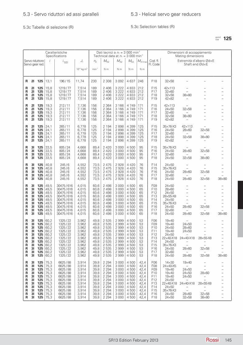
5.3 - Servo riduttori ad assi paralleli 5.3 - Helical servo gear reducers
145SR13 Edition February 2013
5.3c Tabelle di selezione (R) 5.3c Selection tables (R)
CaratteristicheSpecifications
Dati tecnici a n1 = 3 000 min-1
Technical data at n1 = 3 000 min-1Dimensioni di accoppiamento
Mating dimensionsServo riduttoreServo gear red.
i J1 n2 MN2 MA2 ME2 MA1max Cod. fl. Fl. Code
Estremità d’albero Ød×EShaft end Ød×E
10-4 kg m2 min-1 N m N m N m N m
R 2I 125 13,1 196 / 15 11,74 230 2 308 3 092 4 637 246 F18 32×58 – – –
R 2I 125 15,8 1219 / 77 7,514 189 2 406 3 222 4 833 212 F15 42×113 – – –R 2I 125 15,8 1219 / 77 7,514 189 2 406 3 222 4 833 212 F17 32×60 – – –R 2I 125 15,8 1219 / 77 7,514 189 2 406 3 222 4 833 212 F18 32×58 38×80 – –R 2I 125 15,8 1219 / 77 7,514 189 2 406 3 222 4 833 212 F19 42×82 – – –
R 2I 125 19,3 212 / 11 7,136 156 2 364 3 166 4 749 171 F15 42×113 – – –R 2I 125 19,3 212 / 11 7,136 156 2 364 3 166 4 749 171 F16 24×50 32×58 – –R 2I 125 19,3 212 / 11 7,136 156 2 364 3 166 4 749 171 F17 32×60 – – –R 2I 125 19,3 212 / 11 7,136 156 2 364 3 166 4 749 171 F18 32×58 38×80 – –R 2I 125 19,3 212 / 11 7,136 156 2 364 3 166 4 749 171 F19 42×82 – – –
R 2I 125 24,1 265 / 11 6,778 125 2 194 2 898 4 399 125 F15 35×76-X3 42×113 – –R 2I 125 24,1 265 / 11 6,778 125 2 194 2 898 4 399 125 F16 24×50 28×60 32×58 –R 2I 125 24,1 265 / 11 6,778 125 2 194 2 898 4 399 125 F17 32×60 – – –R 2I 125 24,1 265 / 11 6,778 125 2 194 2 898 4 399 125 F18 24×50 32×58 38×80 –R 2I 125 24,1 265 / 11 6,778 125 2 194 2 898 4 399 125 F19 42×82 – – –
R 3I 125 33,5 805 / 24 4,668 89,4 2 420 3 000 4 500 95 F15 35×76-X3 – – –R 3I 125 33,5 805 / 24 4,668 89,4 2 420 3 000 4 500 95 F16 24×50 28×60 32×58 –R 3I 125 33,5 805 / 24 4,668 89,4 2 420 3 000 4 500 95 F17 32×60 – – –R 3I 125 33,5 805 / 24 4,668 89,4 2 420 3 000 4 500 95 F18 24×50 32×58 38×80 –
R 3I 125 40,8 245 / 6 4,552 73,5 2 475 2 928 4 420 76 F14 24×50 – – –R 3I 125 40,8 245 / 6 4,552 73,5 2 475 2 928 4 420 76 F15 35×76-X3 – – –R 3I 125 40,8 245 / 6 4,552 73,5 2 475 2 928 4 420 76 F16 24×50 28×60 32×58 –R 3I 125 40,8 245 / 6 4,552 73,5 2 475 2 928 4 420 76 F17 32×60 – – –R 3I 125 40,8 245 / 6 4,552 73,5 2 475 2 928 4 420 76 F18 24×50 28×60 32×58 38×80
R 3I 125 49,5 30475 / 616 4,015 60,6 2 498 3 000 4 500 65 F09 24×50 – – –R 3I 125 49,5 30475 / 616 4,015 60,6 2 498 3 000 4 500 65 F10 28×60 – – –R 3I 125 49,5 30475 / 616 4,015 60,6 2 498 3 000 4 500 65 F12 24×50 – – –R 3I 125 49,5 30475 / 616 4,015 60,6 2 498 3 000 4 500 65 F13 28×55-X8 – – –R 3I 125 49,5 30475 / 616 4,015 60,6 2 498 3 000 4 500 65 F14 24×50 – – –R 3I 125 49,5 30475 / 616 4,015 60,6 2 498 3 000 4 500 65 F15 35×76-X3 – – –R 3I 125 49,5 30475 / 616 4,015 60,6 2 498 3 000 4 500 65 F16 24×50 28×60 32×58 –R 3I 125 49,5 30475 / 616 4,015 60,6 2 498 3 000 4 500 65 F17 32×60 – – –R 3I 125 49,5 30475 / 616 4,015 60,6 2 498 3 000 4 500 65 F18 24×50 28×60 32×58 38×80
R 3I 125 60,2 1325 / 22 3,962 49,8 2 535 2 999 4 500 53 F06 19×40 – – –R 3I 125 60,2 1325 / 22 3,962 49,8 2 535 2 999 4 500 53 F09 19×40 24×50 – –R 3I 125 60,2 1325 / 22 3,962 49,8 2 535 2 999 4 500 53 F10 24×50 28×60 – –R 3I 125 60,2 1325 / 22 3,962 49,8 2 535 2 999 4 500 53 F11 19×40 24×50 – –R 3I 125 60,2 1325 / 22 3,962 49,8 2 535 2 999 4 500 53 F12 24×50 – – –R 3I 125 60,2 1325 / 22 3,962 49,8 2 535 2 999 4 500 53 F13 22×40-X18 24×40-X18 28×55-X8 –R 3I 125 60,2 1325 / 22 3,962 49,8 2 535 2 999 4 500 53 F14 24×50 – – –R 3I 125 60,2 1325 / 22 3,962 49,8 2 535 2 999 4 500 53 F15 35×76-X3 – – –R 3I 125 60,2 1325 / 22 3,962 49,8 2 535 2 999 4 500 53 F16 24×50 28×60 32×58 –R 3I 125 60,2 1325 / 22 3,962 49,8 2 535 2 999 4 500 53 F17 32×60 – – –R 3I 125 60,2 1325 / 22 3,962 49,8 2 535 2 999 4 500 53 F18 24×50 28×60 32×58 38×80
R 3I 125 75,3 6625 / 88 3,914 39,8 2 294 3 000 4 500 42,4 F06 14×30 19×40 – –R 3I 125 75,3 6625 / 88 3,914 39,8 2 294 3 000 4 500 42,4 F08 24×40-X5 – – –R 3I 125 75,3 6625 / 88 3,914 39,8 2 294 3 000 4 500 42,4 F09 19×40 24×50 – –R 3I 125 75,3 6625 / 88 3,914 39,8 2 294 3 000 4 500 42,4 F10 19×40 24×50 28×60 –R 3I 125 75,3 6625 / 88 3,914 39,8 2 294 3 000 4 500 42,4 F11 19×40 24×50 – –R 3I 125 75,3 6625 / 88 3,914 39,8 2 294 3 000 4 500 42,4 F12 24×50 – – –R 3I 125 75,3 6625 / 88 3,914 39,8 2 294 3 000 4 500 42,4 F13 22×40-X18 24×40-X18 28×55-X8 –R 3I 125 75,3 6625 / 88 3,914 39,8 2 294 3 000 4 500 42,4 F14 24×50 – – –R 3I 125 75,3 6625 / 88 3,914 39,8 2 294 3 000 4 500 42,4 F15 35×76-X3 – – –R 3I 125 75,3 6625 / 88 3,914 39,8 2 294 3 000 4 500 42,4 F16 24×50 28×60 32×58 –R 3I 125 75,3 6625 / 88 3,914 39,8 2 294 3 000 4 500 42,4 F18 24×50 32×58 38×80 –
i esattoexact
grand. size 125
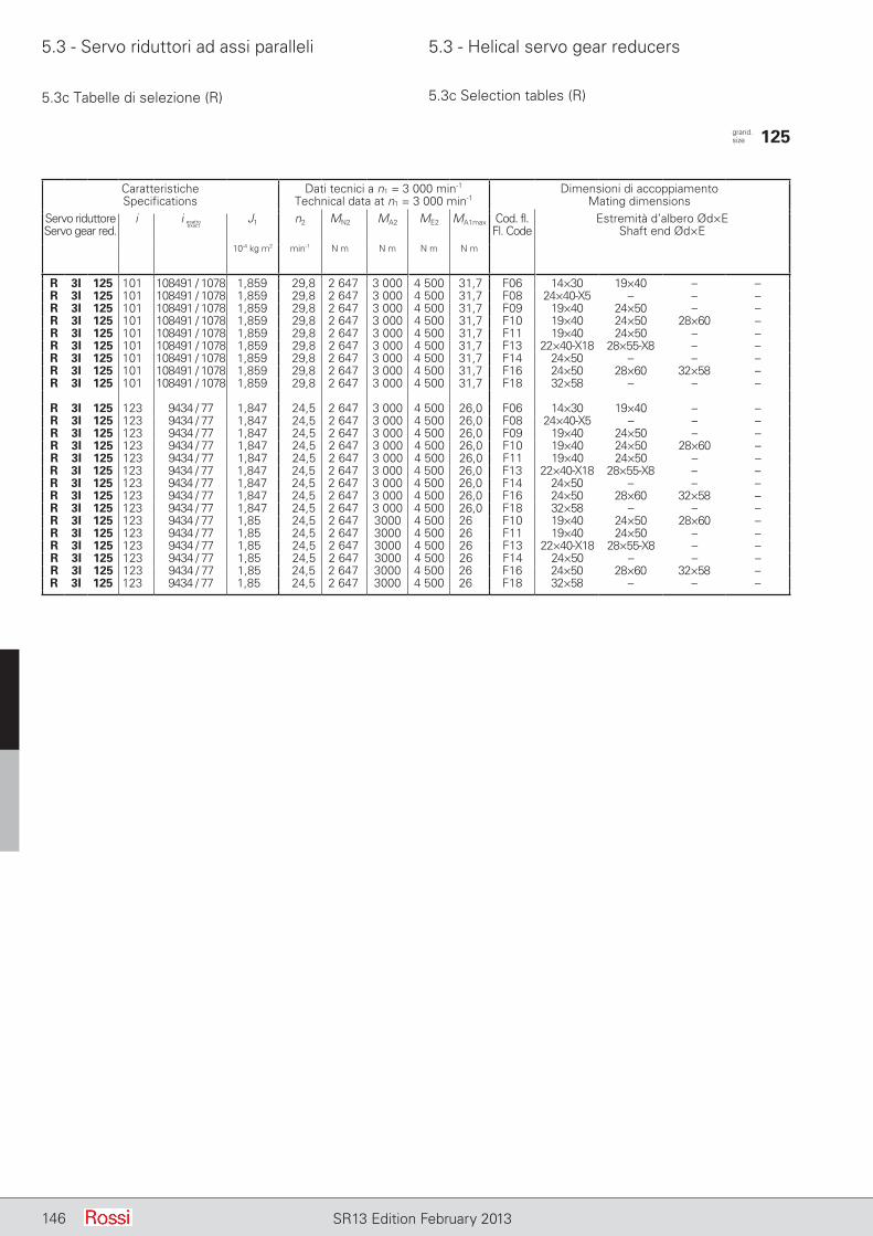
5.3 - Servo riduttori ad assi paralleli 5.3 - Helical servo gear reducers
146 SR13 Edition February 2013146 SR13 Edition February 2013
5.3c Tabelle di selezione (R) 5.3c Selection tables (R)
CaratteristicheSpecifications
Dati tecnici a n1 = 3 000 min-1
Technical data at n1 = 3 000 min-1Dimensioni di accoppiamento
Mating dimensionsServo riduttoreServo gear red.
i J1 n2 MN2 MA2 ME2 MA1max Cod. fl. Fl. Code
Estremità d’albero Ød×EShaft end Ød×E
10-4 kg m2 min-1 N m N m N m N m
R 3I 125 101 108491 / 1078 1,859 29,8 2 647 3 000 4 500 31,7 F06 14×30 19×40 – –R 3I 125 101 108491 / 1078 1,859 29,8 2 647 3 000 4 500 31,7 F08 24×40-X5 – – –R 3I 125 101 108491 / 1078 1,859 29,8 2 647 3 000 4 500 31,7 F09 19×40 24×50 – –R 3I 125 101 108491 / 1078 1,859 29,8 2 647 3 000 4 500 31,7 F10 19×40 24×50 28×60 –R 3I 125 101 108491 / 1078 1,859 29,8 2 647 3 000 4 500 31,7 F11 19×40 24×50 – –R 3I 125 101 108491 / 1078 1,859 29,8 2 647 3 000 4 500 31,7 F13 22×40-X18 28×55-X8 – –R 3I 125 101 108491 / 1078 1,859 29,8 2 647 3 000 4 500 31,7 F14 24×50 – – –R 3I 125 101 108491 / 1078 1,859 29,8 2 647 3 000 4 500 31,7 F16 24×50 28×60 32×58 –R 3I 125 101 108491 / 1078 1,859 29,8 2 647 3 000 4 500 31,7 F18 32×58 – – –
R 3I 125 123 9434 / 77 1,847 24,5 2 647 3 000 4 500 26,0 F06 14×30 19×40 – –R 3I 125 123 9434 / 77 1,847 24,5 2 647 3 000 4 500 26,0 F08 24×40-X5 – – –R 3I 125 123 9434 / 77 1,847 24,5 2 647 3 000 4 500 26,0 F09 19×40 24×50 – –R 3I 125 123 9434 / 77 1,847 24,5 2 647 3 000 4 500 26,0 F10 19×40 24×50 28×60 –R 3I 125 123 9434 / 77 1,847 24,5 2 647 3 000 4 500 26,0 F11 19×40 24×50 – –R 3I 125 123 9434 / 77 1,847 24,5 2 647 3 000 4 500 26,0 F13 22×40-X18 28×55-X8 – –R 3I 125 123 9434 / 77 1,847 24,5 2 647 3 000 4 500 26,0 F14 24×50 – – –R 3I 125 123 9434 / 77 1,847 24,5 2 647 3 000 4 500 26,0 F16 24×50 28×60 32×58 –R 3I 125 123 9434 / 77 1,847 24,5 2 647 3 000 4 500 26,0 F18 32×58 – – –R 3I 125 123 9434 / 77 1,85 24,5 2 647 3000 4 500 26 F10 19×40 24×50 28×60 –R 3I 125 123 9434 / 77 1,85 24,5 2 647 3000 4 500 26 F11 19×40 24×50 – –R 3I 125 123 9434 / 77 1,85 24,5 2 647 3000 4 500 26 F13 22×40-X18 28×55-X8 – –R 3I 125 123 9434 / 77 1,85 24,5 2 647 3000 4 500 26 F14 24×50 – – –R 3I 125 123 9434 / 77 1,85 24,5 2 647 3000 4 500 26 F16 24×50 28×60 32×58 –R 3I 125 123 9434 / 77 1,85 24,5 2 647 3000 4 500 26 F18 32×58 – – –
i esattoexact
grand. size 125
147SR13 Edition February 2013
Pagina lasciata intenzionalmente biancaThis page is intentionally left blank

5.3 - Servo riduttori ad assi paralleli 5.3 - Helical servo gear reducers
148 SR13 Edition February 2013
5.3d Esecuzioni, dimensioni, forme costruttive e quantità d'olio (R)
5.3d Designs, dimensions, mounting positions and oil quantities (R)
R 2I 50 ... 125
Esecuzione (senso di rotazione)Design (direction of rotation)
d Posizione gola di riferimento (ved. cap. 5.6) per la verifica del carico radiale.
d Position of the reference groove (see ch. 5.6) for verification of radial load.
Grand.Size
a A B c1 D d1 e1 F G H H1 h K L M N P Q T U W1 W2 Y1 Z MassaMass∅ ∅ ∅ ∅ ∅ ∅
H7 h11 h11 h6 max1) iN ≤ 12,5 iN ≥ 16 kg
50 90 86 75 51 24 14 30 M6 79 67 49 50 9,5 12 85 70 105 2,5 120 95 80 217 150 149 53 1363 113 102 90 61 30 16 30 M8 90 80 58,5 62 11,5 14 100 80 120 3 143 114 100 255 224 156 63 2164 115 102 90 61 32 16 30 M8 90 80 58,5 62 11,5 14 100 80 120 3 143 114 100 257 202 160 63 21
80 142,5 132 106 72 38 19 40 M10 108 100 69,5 70 14 17 130 110 160 3,5 180 135 100 313 227 212 75 3881 142,5 132 106 72 40 19 40 M10 108 100 69,5 70 14 17 130 110 160 3,5 180 135 125 313 227 212 75 38
100 180 172 131 87 48 24 50 M12 130 125 84,5 80 16 20 165 130 200 3,5 228 165 125 385 244 256 90 62
125 225 212 162 107 60 28 60 2) 159 150 103,5 100 18 23 215 180 250 4 274 201 166 475 310 310 110 100
1) Lunghezza utile del filetto 2 · F.2) Per dimensione, numero e posizione angolare ved. cap. 5.7.
Salvo diversa indicazione i riduttori vengono forniti nella forma costruttiva normale B3 la quale, in quanto normale, non va indicata nella designazione.
eventuale pompa di lubrificazione cuscinetti o dispositivo lubrificazione asse veloce: in caso di necessità interpellarci.
Unless otherwise stated, gear reducers are supplied in mounting position B3 which, being standard, is omitted from the designation.
possible bearings lubrication pump or high speed shaft lubrication device: consult us if need be.
Grand. B3,B8 B6 B7, V5, V6 Size
50 0,6 0,9 0,8 63, 64 0,9 1,4 1,2 80, 81 1,5 2,7 2,3 100 2,9 5,3 4,5 125 5,6 9,5 8,8
1) Working length of thread 2 · F.2) For dimension, number and angular position see ch. 5.7.
Forme costruttive e quantità d'olio [l] Mounting positions and oil quantities [l]
B3 B6 B7 B8 V5 V6
100
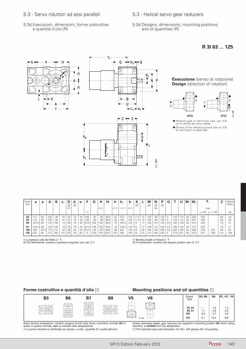
5.3 - Servo riduttori ad assi paralleli 5.3 - Helical servo gear reducers
149SR13 Edition February 2013
5.3d Esecuzioni, dimensioni, forme costruttive e quantità d'olio (R)
5.3d Designs, dimensions, mounting positions and oil quantities (R)
R 3I 63 ... 125
Esecuzione (senso di rotazione)Design (direction of rotation)
d Posizione gola di riferimento (ved. cap. 5.6) per la verifica del carico radiale.
d Position of the reference groove (see ch. 5.6) for verification of radial load.
Grand.Size
a a1 A B c1 D d1 e1 F G H H1 h h0 h1 K L M N P Q T U W1 W2 Y1 Z MassaMass∅ ∅ ∅ ∅ ∅ ∅
H7 h11 h11 h11 h11 h6 max1) iN ≤ 80 iN ≥ 100 kg
63 113 40 102 90 61 30 16 30 M8 90 80 58,5 62 153 102 11,5 14 100 80 120 3 143 114 40 255 192 63 2464 115 40 102 90 61 32 16 30 M8 90 80 58,5 62 155 102 11,5 14 100 80 120 3 143 114 40 257 192 63 2480 142,5 50 132 106 72 38 19 40 M10 108 100 69,5 70 192,5 120 14 17 130 110 160 3,5 180 135 50 313 220 75 41
81 142,5 50 132 106 72 40 19 40 M10 108 100 69,5 70 192,5 120 14 17 130 110 160 3,5 180 135 50 313 220 75 41100 180 62,5 172 131 87 48 24 50 M12 130 125 88,5 80 242 143 16 20 165 130 200 3,5 228 165 62 385 276 251 90 67125 225 80 212 162 107 60 28 60 2) 159 150 103,5 100 295 180 18 23 215 180 250 4 274 201 86 475 337 285 110 108
Forme costruttive e quantità d’olio [l] Mounting positions and oil quantities [l]
Salvo diversa indicazione i riduttori vengono forniti nella forma costruttiva normale B3 la quale, in quanto normale, non va indicata nella designazione.1) La prima riduzione è lubrificata con grasso «a vita» (quantità 5% quella dell’olio).
1) Lunghezza utile del filetto 2 · F.2) Per dimensione, numero e posizione angolare ved. cap. 5.7.
1) Working length of thread 2 · F.2) For dimension, number and angular position see ch. 5.7.
Unless otherwise stated, gear reducers are supplied in mounting position B3 which, being standard, is omitted from the designation.1) First reduction gear pair lubricated «for life» with grease (5% oil quantity).
Grand. B3, B8 B6 B7, V51), V6 Size
63, 64 1,9 1,5 1,3 80, 81 1,7 2,9 2,5 100 3,3 5,7 4,9 125 6,1 10,2 8,8
B3 B6 B7 B8 V5 V6
149
150 SR13 Edition January 2013150 SR12 October 2012
Pagina lasciata intenzionalmente biancaThis page is intentionally left blank
SR13 Edition February 2013150
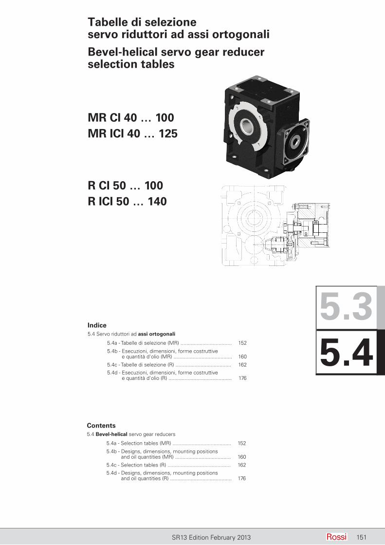
151SR13 Edition February 2013
Tabelle di selezione servo riduttori ad assi ortogonali
Bevel-helical servo gear reducer selection tables
Indice5.4 Servo riduttori ad assi ortogonali
5.4a - Tabelle di selezione (MR) ................................... 152
5.4b - Esecuzioni, dimensioni, forme costruttive e quantità d'olio (MR) ........................................ 160
5.4c - Tabelle di selezione (R) ...................................... 1625.4d - Esecuzioni, dimensioni, forme costruttive
e quantità d'olio (R) ........................................... 176
MR CI 40 … 100MR ICI 40 … 125
R CI 50 … 100R ICI 50 … 140
Contents5.4 Bevel-helical servo gear reducers
5.4a - Selection tables (MR) ........................................ 152
5.4b - Designs, dimensions, mounting positions and oil quantities (MR) ...................................... 160
5.4c - Selection tables (R) ........................................... 1625.4d - Designs, dimensions, mounting positions
and oil quantities (R) .......................................... 176
5.35.4
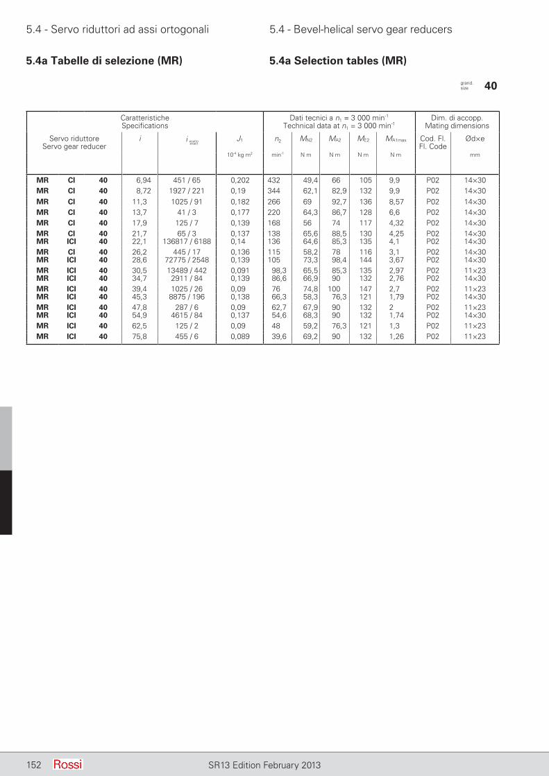
5.4 - Servo riduttori ad assi ortogonali 5.4 - Bevel-helical servo gear reducers
152 SR13 Edition February 2013
5.4a Tabelle di selezione (MR) 5.4a Selection tables (MR)
CaratteristicheSpecifications
Dati tecnici a n1 = 3 000 min-1
Technical data at n1 = 3 000 min-1Dim. di accopp.
Mating dimensions
Servo riduttoreServo gear reducer
i J1 n2 MN2 MA2 ME2 MA1max Cod. Fl.Fl. Code
Ød×e
10-4 kg m2 min-1 N m N m N m N m mm
MR CI 40 6,94 451 / 65 0,202 432 49,4 66 105 9,9 P02 14×30MR CI 40 8,72 1927 / 221 0,19 344 62,1 82,9 132 9,9 P02 14×30MR CI 40 11,3 1025 / 91 0,182 266 69 92,7 136 8,57 P02 14×30MR CI 40 13,7 41 / 3 0,177 220 64,3 86,7 128 6,6 P02 14×30MR CI 40 17,9 125 / 7 0,139 168 56 74 117 4,32 P02 14×30MR CI 40 21,7 65 / 3 0,137 138 65,6 88,5 130 4,25 P02 14×30MR ICI 40 22,1 136817 / 6188 0,14 136 64,6 85,3 135 4,1 P02 14×30MR CI 40 26,2 445 / 17 0,136 115 58,2 78 116 3,1 P02 14×30MR ICI 40 28,6 72775 / 2548 0,139 105 73,3 98,4 144 3,67 P02 14×30MR ICI 40 30,5 13489 / 442 0,091 98,3 65,5 85,3 135 2,97 P02 11×23MR ICI 40 34,7 2911 / 84 0,139 86,6 66,9 90 132 2,76 P02 14×30MR ICI 40 39,4 1025 / 26 0,09 76 74,8 100 147 2,7 P02 11×23MR ICI 40 45,3 8875 / 196 0,138 66,3 58,3 76,3 121 1,79 P02 14×30MR ICI 40 47,8 287 / 6 0,09 62,7 67,9 90 132 2 P02 11×23MR ICI 40 54,9 4615 / 84 0,137 54,6 68,3 90 132 1,74 P02 14×30MR ICI 40 62,5 125 / 2 0,09 48 59,2 76,3 121 1,3 P02 11×23MR ICI 40 75,8 455 / 6 0,089 39,6 69,2 90 132 1,26 P02 11×23
i esattoexact
grand. size 40
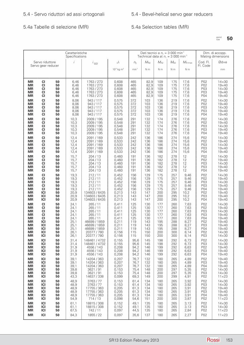
5.4 - Servo riduttori ad assi ortogonali 5.4 - Bevel-helical servo gear reducers
153SR13 Edition February 2013
5.4a Tabelle di selezione (MR) 5.4a Selection tables (MR)
CaratteristicheSpecifications
Dati tecnici a n1 = 3 000 min-1
Technical data at n1 = 3 000 min-1Dim. di accopp.
Mating dimensions
Servo riduttoreServo gear reducer
i J1 n2 MN2 MA2 ME2 MA1max Cod. Fl.Fl. Code
Ød×e
10-4 kg m2 min-1 N m N m N m N m mm
MR CI 50 6,46 1763 / 273 0,608 465 82,9 109 175 17,6 P02 14×30MR CI 50 6,46 1763 / 273 0,608 465 82,9 109 175 17,6 P02 19×40MR CI 50 6,46 1763 / 273 0,608 465 82,9 109 175 17,6 P03 14×30MR CI 50 6,46 1763 / 273 0,608 465 82,9 109 175 17,6 P03 19×40MR CI 50 6,46 1763 / 273 0,608 465 82,9 109 175 17,6 P04 19×40MR CI 50 8,06 943 / 117 0,575 372 103 136 219 17,6 P02 14×30MR CI 50 8,06 943 / 117 0,575 372 103 136 219 17,6 P02 19×40MR CI 50 8,06 943 / 117 0,575 372 103 136 219 17,6 P03 14×30MR CI 50 8,06 943 / 117 0,575 372 103 136 219 17,6 P03 19×40MR CI 50 8,06 943 / 117 0,575 372 103 136 219 17,6 P04 19×40MR CI 50 10,3 2009 / 195 0,548 291 132 174 276 17,6 P02 14×30MR CI 50 10,3 2009 / 195 0,548 291 132 174 276 17,6 P02 19×40MR CI 50 10,3 2009 / 195 0,548 291 132 174 276 17,6 P03 14×30MR CI 50 10,3 2009 / 195 0,548 291 132 174 276 17,6 P03 19×40MR CI 50 10,3 2009 / 195 0,548 291 132 174 276 17,6 P04 19×40MR CI 50 12,4 2091 / 169 0,533 242 136 186 274 15,6 P02 14×30MR CI 50 12,4 2091 / 169 0,533 242 136 186 274 15,6 P02 19×40MR CI 50 12,4 2091 / 169 0,533 242 136 186 274 15,6 P03 14×30MR CI 50 12,4 2091 / 169 0,533 242 136 186 274 15,6 P03 19×40MR CI 50 12,4 2091 / 169 0,533 242 136 186 274 15,6 P04 19×40MR CI 50 15,7 204 / 13 0,460 191 136 182 278 12 P02 14×30MR CI 50 15,7 204 / 13 0,460 191 136 182 278 12 P02 19×40MR CI 50 15,7 204 / 13 0,460 191 136 182 278 12 P03 14×30MR CI 50 15,7 204 / 13 0,460 191 136 182 278 12 P03 19×40MR CI 50 15,7 204 / 13 0,460 191 136 182 278 12 P04 19×40MR CI 50 19,3 212 / 11 0,452 156 129 175 257 9,46 P02 14×30MR CI 50 19,3 212 / 11 0,452 156 129 175 257 9,46 P02 19×40MR CI 50 19,3 212 / 11 0,452 156 129 175 257 9,46 P03 14×30MR CI 50 19,3 212 / 11 0,452 156 129 175 257 9,46 P03 19×40MR CI 50 19,3 212 / 11 0,452 156 129 175 257 9,46 P04 19×40MR ICI 50 20,9 134603 / 6435 0,213 143 147 200 295 10,2 P02 19×40MR ICI 50 20,9 134603 / 6435 0,213 143 147 200 295 10,2 P03 19×40MR ICI 50 20,9 134603 / 6435 0,213 143 147 200 295 10,2 P04 19×40MR CI 50 24,1 265 / 11 0,411 125 130 177 260 7,63 P02 14×30MR CI 50 24,1 265 / 11 0,411 125 130 177 260 7,63 P02 19×40MR CI 50 24,1 265 / 11 0,411 125 130 177 260 7,63 P03 14×30MR CI 50 24,1 265 / 11 0,411 125 130 177 260 7,63 P03 19×40MR CI 50 24,1 265 / 11 0,411 125 130 177 260 7,63 P04 19×40MR ICI 50 25,1 46699 / 1859 0,211 119 143 195 288 8,27 P02 19×40MR ICI 50 25,1 46699 / 1859 0,211 119 143 195 288 8,27 P03 19×40MR ICI 50 25,1 46699 / 1859 0,211 119 143 195 288 8,27 P04 19×40MR ICI 50 26,1 20377 / 780 0,156 115 150 200 300 8,14 P02 14×30MR ICI 50 26,1 20377 / 780 0,156 115 150 200 300 8,14 P03 14×30MR ICI 50 31,4 148461 / 4732 0,155 95,6 145 198 292 6,73 P02 14×30MR ICI 50 31,4 148461 / 4732 0,155 95,6 145 198 292 6,73 P03 14×30MR ICI 50 31,9 4556 / 143 0,208 94,2 146 199 292 6,63 P02 19×40MR ICI 50 31,9 4556 / 143 0,208 94,2 146 199 292 6,63 P03 19×40MR ICI 50 31,9 4556 / 143 0,208 94,2 146 199 292 6,63 P04 19×40MR ICI 50 39,1 14204 / 363 0,207 76,7 132 180 265 4,89 P02 19×40MR ICI 50 39,1 14204 / 363 0,207 76,7 132 180 265 4,89 P03 19×40MR ICI 50 39,1 14204 / 363 0,207 76,7 132 180 265 4,89 P04 19×40MR ICI 50 39,8 3621 / 91 0,153 75,4 148 200 297 5,35 P02 14×30MR ICI 50 39,8 3621 / 91 0,153 75,4 148 200 297 5,35 P03 14×30MR ICI 50 43,3 14637 / 338 0,099 69,3 149 200 299 4,91 P02 11×23MR ICI 50 48,9 3763 / 77 0,153 61,4 134 180 265 3,92 P02 14×30MR ICI 50 48,9 3763 / 77 0,153 61,4 134 180 265 3,92 P03 14×30MR ICI 50 48,9 17755 / 363 0,205 61,3 134 180 265 3,91 P02 19×40MR ICI 50 48,9 17755 / 363 0,205 61,3 134 180 265 3,91 P03 19×40MR ICI 50 48,9 17755 / 363 0,205 61,3 134 180 265 3,91 P04 19×40MR ICI 50 54,9 714 / 13 0,098 54,6 151 200 300 3,87 P02 11×23MR ICI 50 61,1 18815 / 308 0,152 49,1 135 180 265 3,13 P02 14×30MR ICI 50 61,1 18815 / 308 0,152 49,1 135 180 265 3,13 P03 14×30MR ICI 50 67,5 742 / 11 0,097 44,5 135 180 265 2,84 P02 11×23MR ICI 50 84,3 1855 / 22 0,097 35,6 137 180 265 2,27 P02 11×23
grand. size 50
i esattoexact
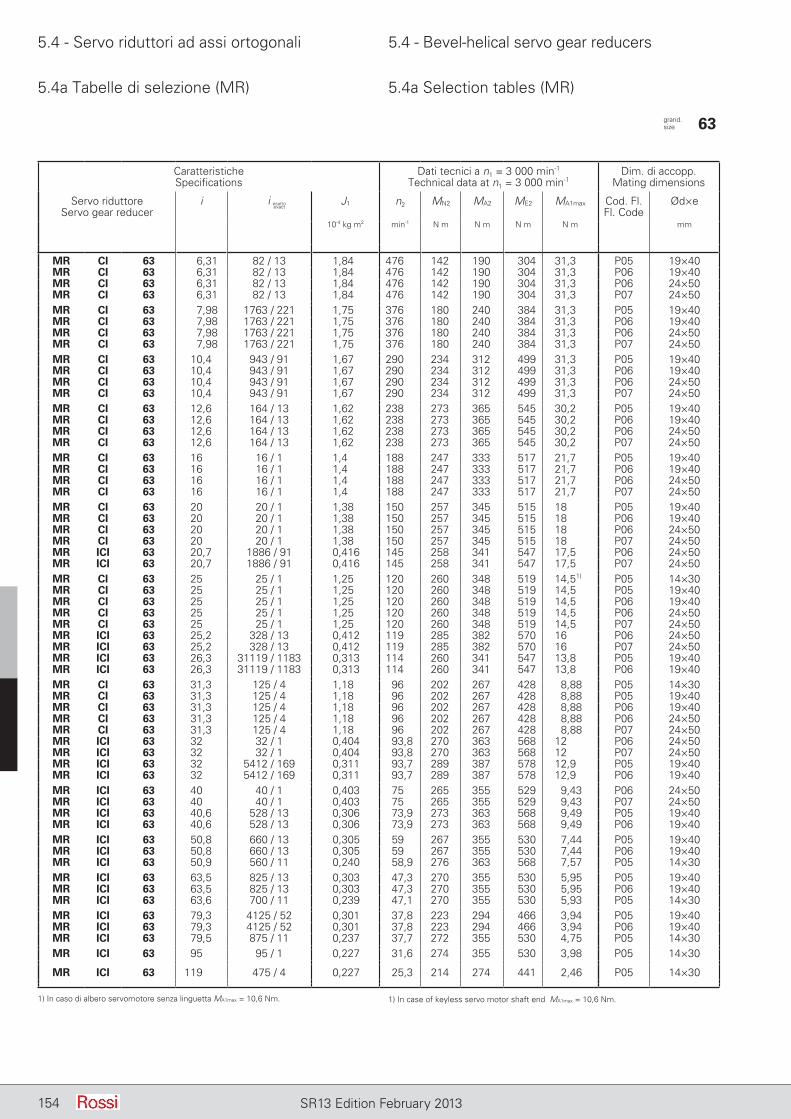
5.4 - Servo riduttori ad assi ortogonali 5.4 - Bevel-helical servo gear reducers
154 SR13 Edition February 2013
5.4a Tabelle di selezione (MR) 5.4a Selection tables (MR)
CaratteristicheSpecifications
Dati tecnici a n1 = 3 000 min-1
Technical data at n1 = 3 000 min-1Dim. di accopp.
Mating dimensions
Servo riduttoreServo gear reducer
i J1 n2 MN2 MA2 ME2 MA1max Cod. Fl.Fl. Code
Ød×e
10-4 kg m2 min-1 N m N m N m N m mm
MR CI 63 6,31 82 / 13 1,84 476 142 190 304 31,3 P05 19×40MR CI 63 6,31 82 / 13 1,84 476 142 190 304 31,3 P06 19×40MR CI 63 6,31 82 / 13 1,84 476 142 190 304 31,3 P06 24×50MR CI 63 6,31 82 / 13 1,84 476 142 190 304 31,3 P07 24×50MR CI 63 7,98 1763 / 221 1,75 376 180 240 384 31,3 P05 19×40MR CI 63 7,98 1763 / 221 1,75 376 180 240 384 31,3 P06 19×40MR CI 63 7,98 1763 / 221 1,75 376 180 240 384 31,3 P06 24×50MR CI 63 7,98 1763 / 221 1,75 376 180 240 384 31,3 P07 24×50MR CI 63 10,4 943 / 91 1,67 290 234 312 499 31,3 P05 19×40MR CI 63 10,4 943 / 91 1,67 290 234 312 499 31,3 P06 19×40MR CI 63 10,4 943 / 91 1,67 290 234 312 499 31,3 P06 24×50MR CI 63 10,4 943 / 91 1,67 290 234 312 499 31,3 P07 24×50MR CI 63 12,6 164 / 13 1,62 238 273 365 545 30,2 P05 19×40MR CI 63 12,6 164 / 13 1,62 238 273 365 545 30,2 P06 19×40MR CI 63 12,6 164 / 13 1,62 238 273 365 545 30,2 P06 24×50MR CI 63 12,6 164 / 13 1,62 238 273 365 545 30,2 P07 24×50MR CI 63 16 16 / 1 1,4 188 247 333 517 21,7 P05 19×40MR CI 63 16 16 / 1 1,4 188 247 333 517 21,7 P06 19×40MR CI 63 16 16 / 1 1,4 188 247 333 517 21,7 P06 24×50MR CI 63 16 16 / 1 1,4 188 247 333 517 21,7 P07 24×50MR CI 63 20 20 / 1 1,38 150 257 345 515 18 P05 19×40MR CI 63 20 20 / 1 1,38 150 257 345 515 18 P06 19×40MR CI 63 20 20 / 1 1,38 150 257 345 515 18 P06 24×50MR CI 63 20 20 / 1 1,38 150 257 345 515 18 P07 24×50MR ICI 63 20,7 1886 / 91 0,416 145 258 341 547 17,5 P06 24×50MR ICI 63 20,7 1886 / 91 0,416 145 258 341 547 17,5 P07 24×50MR CI 63 25 25 / 1 1,25 120 260 348 519 14,51) P05 14×30MR CI 63 25 25 / 1 1,25 120 260 348 519 14,5 P05 19×40MR CI 63 25 25 / 1 1,25 120 260 348 519 14,5 P06 19×40MR CI 63 25 25 / 1 1,25 120 260 348 519 14,5 P06 24×50MR CI 63 25 25 / 1 1,25 120 260 348 519 14,5 P07 24×50MR ICI 63 25,2 328 / 13 0,412 119 285 382 570 16 P06 24×50MR ICI 63 25,2 328 / 13 0,412 119 285 382 570 16 P07 24×50MR ICI 63 26,3 31119 / 1183 0,313 114 260 341 547 13,8 P05 19×40MR ICI 63 26,3 31119 / 1183 0,313 114 260 341 547 13,8 P06 19×40MR CI 63 31,3 125 / 4 1,18 96 202 267 428 8,88 P05 14×30MR CI 63 31,3 125 / 4 1,18 96 202 267 428 8,88 P05 19×40MR CI 63 31,3 125 / 4 1,18 96 202 267 428 8,88 P06 19×40MR CI 63 31,3 125 / 4 1,18 96 202 267 428 8,88 P06 24×50MR CI 63 31,3 125 / 4 1,18 96 202 267 428 8,88 P07 24×50MR ICI 63 32 32 / 1 0,404 93,8 270 363 568 12 P06 24×50MR ICI 63 32 32 / 1 0,404 93,8 270 363 568 12 P07 24×50MR ICI 63 32 5412 / 169 0,311 93,7 289 387 578 12,9 P05 19×40MR ICI 63 32 5412 / 169 0,311 93,7 289 387 578 12,9 P06 19×40MR ICI 63 40 40 / 1 0,403 75 265 355 529 9,43 P06 24×50MR ICI 63 40 40 / 1 0,403 75 265 355 529 9,43 P07 24×50MR ICI 63 40,6 528 / 13 0,306 73,9 273 363 568 9,49 P05 19×40MR ICI 63 40,6 528 / 13 0,306 73,9 273 363 568 9,49 P06 19×40MR ICI 63 50,8 660 / 13 0,305 59 267 355 530 7,44 P05 19×40MR ICI 63 50,8 660 / 13 0,305 59 267 355 530 7,44 P06 19×40MR ICI 63 50,9 560 / 11 0,240 58,9 276 363 568 7,57 P05 14×30MR ICI 63 63,5 825 / 13 0,303 47,3 270 355 530 5,95 P05 19×40MR ICI 63 63,5 825 / 13 0,303 47,3 270 355 530 5,95 P06 19×40MR ICI 63 63,6 700 / 11 0,239 47,1 270 355 530 5,93 P05 14×30MR ICI 63 79,3 4125 / 52 0,301 37,8 223 294 466 3,94 P05 19×40MR ICI 63 79,3 4125 / 52 0,301 37,8 223 294 466 3,94 P06 19×40MR ICI 63 79,5 875 / 11 0,237 37,7 272 355 530 4,75 P05 14×30MR ICI 63 95 95 / 1 0,227 31,6 274 355 530 3,98 P05 14×30
MR ICI 63 119 475 / 4 0,227 25,3 214 274 441 2,46 P05 14×30
grand. size 63
i esattoexact
1) In caso di albero servomotore senza linguetta MA1max = 10,6 Nm. 1) In case of keyless servo motor shaft end MA1max = 10,6 Nm.
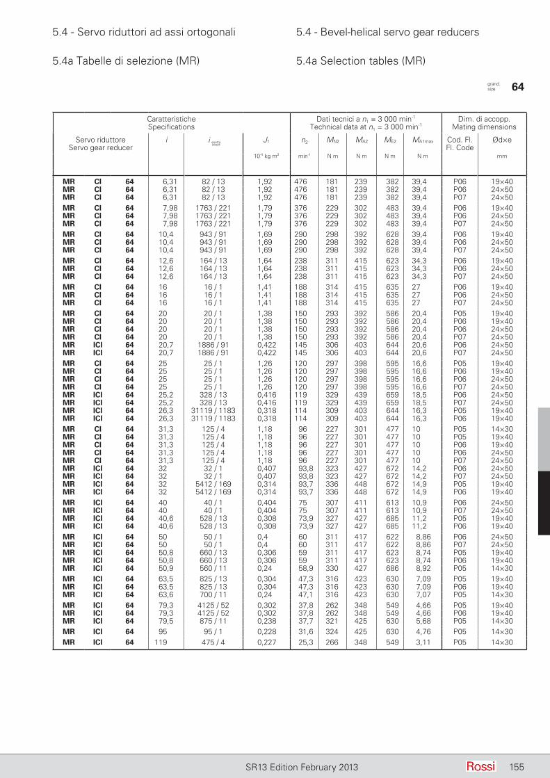
5.4 - Servo riduttori ad assi ortogonali 5.4 - Bevel-helical servo gear reducers
155SR13 Edition February 2013
5.4a Tabelle di selezione (MR) 5.4a Selection tables (MR)
CaratteristicheSpecifications
Dati tecnici a n1 = 3 000 min-1
Technical data at n1 = 3 000 min-1Dim. di accopp.
Mating dimensions
Servo riduttoreServo gear reducer
i J1 n2 MN2 MA2 ME2 MA1max Cod. Fl.Fl. Code
Ød×e
10-4 kg m2 min-1 N m N m N m N m mm
MR CI 64 6,31 82 / 13 1,92 476 181 239 382 39,4 P06 19×40MR CI 64 6,31 82 / 13 1,92 476 181 239 382 39,4 P06 24×50MR CI 64 6,31 82 / 13 1,92 476 181 239 382 39,4 P07 24×50MR CI 64 7,98 1763 / 221 1,79 376 229 302 483 39,4 P06 19×40MR CI 64 7,98 1763 / 221 1,79 376 229 302 483 39,4 P06 24×50MR CI 64 7,98 1763 / 221 1,79 376 229 302 483 39,4 P07 24×50MR CI 64 10,4 943 / 91 1,69 290 298 392 628 39,4 P06 19×40MR CI 64 10,4 943 / 91 1,69 290 298 392 628 39,4 P06 24×50MR CI 64 10,4 943 / 91 1,69 290 298 392 628 39,4 P07 24×50MR CI 64 12,6 164 / 13 1,64 238 311 415 623 34,3 P06 19×40MR CI 64 12,6 164 / 13 1,64 238 311 415 623 34,3 P06 24×50MR CI 64 12,6 164 / 13 1,64 238 311 415 623 34,3 P07 24×50MR CI 64 16 16 / 1 1,41 188 314 415 635 27 P06 19×40MR CI 64 16 16 / 1 1,41 188 314 415 635 27 P06 24×50MR CI 64 16 16 / 1 1,41 188 314 415 635 27 P07 24×50MR CI 64 20 20 / 1 1,38 150 293 392 586 20,4 P05 19×40MR CI 64 20 20 / 1 1,38 150 293 392 586 20,4 P06 19×40MR CI 64 20 20 / 1 1,38 150 293 392 586 20,4 P06 24×50MR CI 64 20 20 / 1 1,38 150 293 392 586 20,4 P07 24×50MR ICI 64 20,7 1886 / 91 0,422 145 306 403 644 20,6 P06 24×50MR ICI 64 20,7 1886 / 91 0,422 145 306 403 644 20,6 P07 24×50MR CI 64 25 25 / 1 1,26 120 297 398 595 16,6 P05 19×40MR CI 64 25 25 / 1 1,26 120 297 398 595 16,6 P06 19×40MR CI 64 25 25 / 1 1,26 120 297 398 595 16,6 P06 24×50MR CI 64 25 25 / 1 1,26 120 297 398 595 16,6 P07 24×50MR ICI 64 25,2 328 / 13 0,416 119 329 439 659 18,5 P06 24×50MR ICI 64 25,2 328 / 13 0,416 119 329 439 659 18,5 P07 24×50MR ICI 64 26,3 31119 / 1183 0,318 114 309 403 644 16,3 P05 19×40MR ICI 64 26,3 31119 / 1183 0,318 114 309 403 644 16,3 P06 19×40MR CI 64 31,3 125 / 4 1,18 96 227 301 477 10 P05 14×30MR CI 64 31,3 125 / 4 1,18 96 227 301 477 10 P05 19×40MR CI 64 31,3 125 / 4 1,18 96 227 301 477 10 P06 19×40MR CI 64 31,3 125 / 4 1,18 96 227 301 477 10 P06 24×50MR CI 64 31,3 125 / 4 1,18 96 227 301 477 10 P07 24×50MR ICI 64 32 32 / 1 0,407 93,8 323 427 672 14,2 P06 24×50MR ICI 64 32 32 / 1 0,407 93,8 323 427 672 14,2 P07 24×50MR ICI 64 32 5412 / 169 0,314 93,7 336 448 672 14,9 P05 19×40MR ICI 64 32 5412 / 169 0,314 93,7 336 448 672 14,9 P06 19×40MR ICI 64 40 40 / 1 0,404 75 307 411 613 10,9 P06 24×50MR ICI 64 40 40 / 1 0,404 75 307 411 613 10,9 P07 24×50MR ICI 64 40,6 528 / 13 0,308 73,9 327 427 685 11,2 P05 19×40MR ICI 64 40,6 528 / 13 0,308 73,9 327 427 685 11,2 P06 19×40MR ICI 64 50 50 / 1 0,4 60 311 417 622 8,86 P06 24×50MR ICI 64 50 50 / 1 0,4 60 311 417 622 8,86 P07 24×50MR ICI 64 50,8 660 / 13 0,306 59 311 417 623 8,74 P05 19×40MR ICI 64 50,8 660 / 13 0,306 59 311 417 623 8,74 P06 19×40MR ICI 64 50,9 560 / 11 0,24 58,9 330 427 686 8,92 P05 14×30MR ICI 64 63,5 825 / 13 0,304 47,3 316 423 630 7,09 P05 19×40MR ICI 64 63,5 825 / 13 0,304 47,3 316 423 630 7,09 P06 19×40MR ICI 64 63,6 700 / 11 0,24 47,1 316 423 630 7,07 P05 14×30MR ICI 64 79,3 4125 / 52 0,302 37,8 262 348 549 4,66 P05 19×40MR ICI 64 79,3 4125 / 52 0,302 37,8 262 348 549 4,66 P06 19×40MR ICI 64 79,5 875 / 11 0,238 37,7 321 425 630 5,68 P05 14×30MR ICI 64 95 95 / 1 0,228 31,6 324 425 630 4,76 P05 14×30MR ICI 64 119 475 / 4 0,227 25,3 266 348 549 3,11 P05 14×30
grand. size 64
i esattoexact
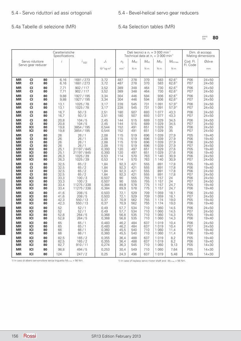
5.4 - Servo riduttori ad assi ortogonali 5.4 - Bevel-helical servo gear reducers
156 SR13 Edition February 2013
5.4a Tabelle di selezione (MR) 5.4a Selection tables (MR)
CaratteristicheSpecifications
Dati tecnici a n1 = 3 000 min-1
Technical data at n1 = 3 000 min-1Dim. di accopp.
Mating dimensions
Servo riduttoreServo gear reducer
i J1 n2 MN2 MA2 ME2 MA1max Cod. Fl.Fl. Code
Ød×e
10-4 kg m2 min-1 N m N m N m N m mm
MR CI 80 6,16 1681 / 273 3,72 487 278 370 583 62,61) P06 24×50MR CI 80 6,16 1681 / 273 3,72 487 278 370 583 62,61) P07 24×50MR CI 80 7,71 902 / 117 3,52 389 348 464 730 62,61) P06 24×50MR CI 80 7,71 902 / 117 3,52 389 348 464 730 62,61) P07 24×50MR CI 80 9,88 1927 / 195 3,34 304 446 594 936 62,61) P06 24×50MR CI 80 9,88 1927 / 195 3,34 304 446 594 936 62,61) P07 24×50MR CI 80 13,1 1025 / 78 3,17 228 545 731 1 091 57,91) P06 24×50MR CI 80 13,1 1025 / 78 3,17 228 545 731 1 091 57,91) P07 24×50MR CI 80 16,7 50 / 3 2,51 180 507 693 1 077 43,3 P06 24×50MR CI 80 16,7 50 / 3 2,51 180 507 693 1 077 43,3 P07 24×50MR CI 80 20,8 104 / 5 2,45 144 515 689 1 029 34,5 P06 24×50MR CI 80 20,8 104 / 5 2,45 144 515 689 1 029 34,5 P07 24×50MR ICI 80 19,8 3854 / 195 0,544 152 491 651 1 029 35 P06 24×50MR ICI 80 19,8 3854 / 195 0,544 152 491 651 1 029 35 P07 24×50MR CI 80 26 26 / 1 2,08 115 519 696 1 039 27,9 P05 19×40MR CI 80 26 26 / 1 2,08 115 519 696 1 039 27,9 P06 19×40MR CI 80 26 26 / 1 2,08 115 519 696 1 039 27,9 P06 24×50MR CI 80 26 26 / 1 2,08 115 519 696 1 039 27,9 P07 24×50MR ICI 80 25,1 21197 / 845 0,393 120 497 651 1 029 27,6 P05 19×40MR ICI 80 25,1 21197 / 845 0,393 120 497 651 1 029 27,6 P06 19×40MR ICI 80 26,3 1025 / 39 0,53 114 570 763 1 140 30,9 P06 24×50MR ICI 80 26,3 1025 / 39 0,53 114 570 763 1 140 30,9 P07 24×50MR CI 80 32,5 65 / 2 1,84 92,3 421 555 891 17,8 P05 19×40MR CI 80 32,5 65 / 2 1,84 92,3 421 555 891 17,8 P06 19×40MR CI 80 32,5 65 / 2 1,84 92,3 421 555 891 17,8 P06 24×50MR CI 80 32,5 65 / 2 1,84 92,3 421 555 891 17,8 P07 24×50MR ICI 80 33,3 100 / 3 0,507 90 555 755 1 157 24 P06 24×50MR ICI 80 33,3 100 / 3 0,507 90 555 755 1 157 24 P07 24×50MR ICI 80 33,4 11275 / 338 0,384 89,9 578 775 1 157 24,7 P05 19×40MR ICI 80 33,4 11275 / 338 0,384 89,9 578 775 1 157 24,7 P06 19×40MR ICI 80 41,6 208 / 5 0,503 72,1 529 709 1 059 18,1 P06 24×50MR ICI 80 41,6 208 / 5 0,503 72,1 529 709 1 059 18,1 P07 24×50MR ICI 80 42,3 550 / 13 0,37 70,9 562 755 1 174 19,0 P05 19×40MR ICI 80 42,3 550 / 13 0,37 70,9 562 755 1 174 19,0 P06 19×40MR ICI 80 52 52 / 1 0,49 57,7 534 710 1 060 14,5 P06 24×50MR ICI 80 52 52 / 1 0,49 57,7 534 710 1 060 14,5 P07 24×50MR ICI 80 52,8 264 / 5 0,368 56,8 535 710 1 060 14,3 P05 19×40MR ICI 80 52,8 264 / 5 0,368 56,8 535 710 1 060 14,3 P06 19×40MR ICI 80 65 65 / 1 0,483 46,2 484 637 1 019 10,4 P06 24×50MR ICI 80 65 65 / 1 0,483 46,2 484 637 1 019 10,4 P07 24×50MR ICI 80 66 66 / 1 0,360 45,5 540 710 1 060 11,4 P05 19×40MR ICI 80 66 66 / 1 0,360 45,5 540 710 1 060 11,4 P06 19×40MR ICI 80 82,5 165 / 2 0,355 36,4 488 637 1 019 8,2 P05 19×40MR ICI 80 82,5 165 / 2 0,355 36,4 488 637 1 019 8,2 P06 19×40MR ICI 80 82,7 910 / 11 0,274 36,3 545 710 1 060 9,13 P05 14×30MR ICI 80 98,8 494 / 5 0,253 30,4 549 710 1 060 7,64 P05 14×30MR ICI 80 124 247 / 2 0,25 24,3 496 637 1 019 5,48 P05 14×30
grand. size 80
i esattoexact
1) In caso di albero servomotore senza linguetta MA1max = 56 Nm. 1) In case of keyless servo motor shaft end MA1max = 56 Nm.
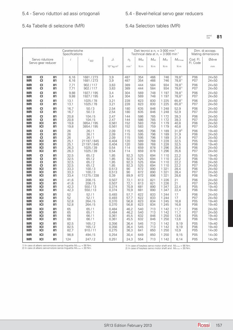
5.4 - Servo riduttori ad assi ortogonali 5.4 - Bevel-helical servo gear reducers
157SR13 Edition February 2013
5.4a Tabelle di selezione (MR) 5.4a Selection tables (MR)
CaratteristicheSpecifications
Dati tecnici a n1 = 3 000 min-1
Technical data at n1 = 3 000 min-1Dim. di accopp.
Mating dimensions
Servo riduttoreServo gear reducer
i J1 n2 MN2 MA2 ME2 MA1max Cod. Fl.Fl. Code
Ød×e
10-4 kg m2 min-1 N m N m N m N m mm
MR CI 81 6,16 1681 / 273 3,9 487 354 466 746 78,81) P06 24×50MR CI 81 6,16 1681 / 273 3,9 487 354 466 746 78,81) P07 24×50MR CI 81 7,71 902 / 117 3,63 389 444 584 934 78,81) P06 24×50MR CI 81 7,71 902 / 117 3,63 389 444 584 934 78,81) P07 24×50MR CI 81 9,88 1927 / 195 3,4 304 569 748 1 197 78,81) P06 24×50MR CI 81 9,88 1927 / 195 3,4 304 569 748 1 197 78,81) P07 24×50MR CI 81 13,1 1025 / 78 3,21 228 623 830 1 225 65,81) P06 24×50MR CI 81 13,1 1025 / 78 3,21 228 623 830 1 225 65,81) P07 24×50MR CI 81 16,7 50 / 3 2,54 180 635 846 1 248 52,9 P06 24×50MR CI 81 16,7 50 / 3 2,54 180 635 846 1 248 52,9 P07 24×50MR CI 81 20,8 104 / 5 2,47 144 586 785 1 172 39,3 P06 24×50MR CI 81 20,8 104 / 5 2,47 144 586 785 1 172 39,3 P07 24×50MR ICI 81 19,8 3854 / 195 0,561 152 583 759 1 179 40,8 P06 24×50MR ICI 81 19,8 3854 / 195 0,561 152 583 759 1 179 40,8 P07 24×50MR CI 81 26 26 / 1 2,09 115 595 796 1 189 31,92) P06 19×40MR CI 81 26 26 / 1 2,09 115 595 796 1 189 31,9 P06 24×50MR CI 81 26 26 / 1 2,09 115 595 796 1 189 31,9 P07 24×50MR ICI 81 25,1 21197 / 845 0,404 120 589 768 1 228 32,5 P05 19×40MR ICI 81 25,1 21197 / 845 0,404 120 589 768 1 228 32,5 P06 19×40MR ICI 81 26,3 1025 / 39 0,54 114 659 878 1 296 35,6 P06 24×50MR ICI 81 26,3 1025 / 39 0,54 114 659 878 1 296 35,6 P07 24×50MR CI 81 32,5 65 / 2 1,85 92,3 525 694 1 110 22,2 P05 19×40MR CI 81 32,5 65 / 2 1,85 92,3 525 694 1 110 22,2 P06 19×40MR CI 81 32,5 65 / 2 1,85 92,3 525 694 1 110 22,2 P06 24×50MR CI 81 32,5 65 / 2 1,85 92,3 525 694 1 110 22,2 P07 24×50MR ICI 81 33,3 100 / 3 0,513 90 672 890 1 321 28,4 P06 24×50MR ICI 81 33,3 100 / 3 0,513 90 672 890 1 321 28,4 P07 24×50MR ICI 81 33,4 11275 / 338 0,39 89,9 672 896 1 321 28,6 P06 19×40MR ICI 81 41,6 208 / 5 0,507 72,1 613 821 1 226 21 P06 24×50MR ICI 81 41,6 208 / 5 0,507 72,1 613 821 1 226 21 P07 24×50MR ICI 81 42,3 550 / 13 0,374 70,9 681 890 1 347 22,4 P05 19×40MR ICI 81 42,3 550 / 13 0,374 70,9 681 890 1 347 22,4 P06 19×40MR ICI 81 52 52 / 1 0,493 57,7 622 833 1 244 17 P06 24×50MR ICI 81 52 52 / 1 0,493 57,7 622 833 1 244 17 P07 24×50MR ICI 81 52,8 264 / 5 0,370 56,8 623 834 1 245 16,8 P05 19×40MR ICI 81 52,8 264 / 5 0,370 56,8 623 834 1 245 16,8 P06 19×40MR ICI 81 65 65 / 1 0,484 46,2 540 713 1 142 11,7 P06 24×50MR ICI 81 65 65 / 1 0,484 46,2 540 713 1 142 11,7 P07 24×50MR ICI 81 66 66 / 1 0,361 45,5 632 846 1 250 13,6 P05 19×40MR ICI 81 66 66 / 1 0,361 45,5 632 846 1 250 13,6 P06 19×40MR ICI 81 82,5 165 / 2 0,356 36,4 545 713 1 142 9,19 P05 19×40MR ICI 81 82,5 165 / 2 0,356 36,4 545 713 1 142 9,19 P06 19×40MR ICI 81 82,7 910 / 11 0,275 36,3 641 850 1 250 10,9 P05 14×30MR ICI 81 98,8 494 / 5 0,254 30,4 649 850 1 250 9,15 P05 14×30MR ICI 81 124 247 / 2 0,251 24,3 554 713 1 142 6,14 P05 14×30
grand. size 81
i esattoexact
1) In caso di albero servomotore senza linguetta MA1max = 56 Nm.2) In caso di albero servomotore senza linguetta MA1max = 30 Nm.
1) In case of keyless servo motor shaft end MA1max = 56 Nm.2) In case of keyless servo motor shaft end MA1max = 30 Nm.
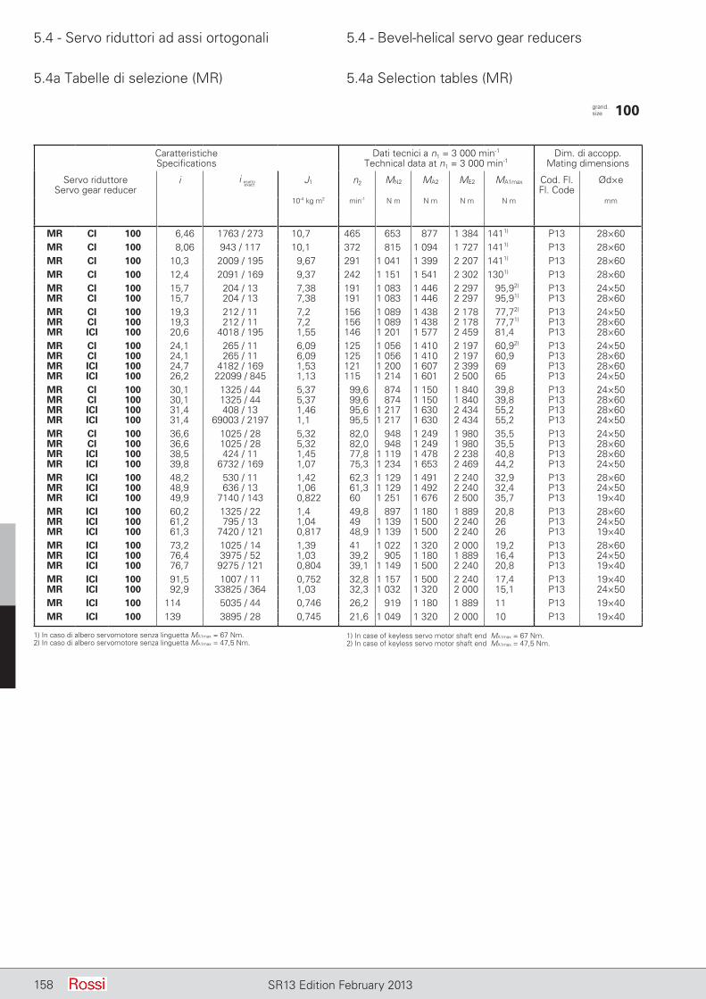
5.4 - Servo riduttori ad assi ortogonali 5.4 - Bevel-helical servo gear reducers
158 SR13 Edition February 2013
5.4a Tabelle di selezione (MR) 5.4a Selection tables (MR)
CaratteristicheSpecifications
Dati tecnici a n1 = 3 000 min-1
Technical data at n1 = 3 000 min-1Dim. di accopp.
Mating dimensions
Servo riduttoreServo gear reducer
i J1 n2 MN2 MA2 ME2 MA1max Cod. Fl.Fl. Code
Ød×e
10-4 kg m2 min-1 N m N m N m N m mm
MR CI 100 6,46 1763 / 273 10,7 465 653 877 1 384 1411) P13 28×60MR CI 100 8,06 943 / 117 10,1 372 815 1 094 1 727 1411) P13 28×60MR CI 100 10,3 2009 / 195 9,67 291 1 041 1 399 2 207 1411) P13 28×60MR CI 100 12,4 2091 / 169 9,37 242 1 151 1 541 2 302 1301) P13 28×60MR CI 100 15,7 204 / 13 7,38 191 1 083 1 446 2 297 95,92) P13 24×50MR CI 100 15,7 204 / 13 7,38 191 1 083 1 446 2 297 95,91) P13 28×60MR CI 100 19,3 212 / 11 7,2 156 1 089 1 438 2 178 77,72) P13 24×50MR CI 100 19,3 212 / 11 7,2 156 1 089 1 438 2 178 77,71) P13 28×60MR ICI 100 20,6 4018 / 195 1,55 146 1 201 1 577 2 459 81,4 P13 28×60MR CI 100 24,1 265 / 11 6,09 125 1 056 1 410 2 197 60,92) P13 24×50MR CI 100 24,1 265 / 11 6,09 125 1 056 1 410 2 197 60,9 P13 28×60MR ICI 100 24,7 4182 / 169 1,53 121 1 200 1 607 2 399 69 P13 28×60MR ICI 100 26,2 22099 / 845 1,13 115 1 214 1 601 2 500 65 P13 24×50MR CI 100 30,1 1325 / 44 5,37 99,6 874 1 150 1 840 39,8 P13 24×50MR CI 100 30,1 1325 / 44 5,37 99,6 874 1 150 1 840 39,8 P13 28×60MR ICI 100 31,4 408 / 13 1,46 95,6 1 217 1 630 2 434 55,2 P13 28×60MR ICI 100 31,4 69003 / 2197 1,1 95,5 1 217 1 630 2 434 55,2 P13 24×50MR CI 100 36,6 1025 / 28 5,32 82,0 948 1 249 1 980 35,5 P13 24×50MR CI 100 36,6 1025 / 28 5,32 82,0 948 1 249 1 980 35,5 P13 28×60MR ICI 100 38,5 424 / 11 1,45 77,8 1 119 1 478 2 238 40,8 P13 28×60MR ICI 100 39,8 6732 / 169 1,07 75,3 1 234 1 653 2 469 44,2 P13 24×50MR ICI 100 48,2 530 / 11 1,42 62,3 1 129 1 491 2 240 32,9 P13 28×60MR ICI 100 48,9 636 / 13 1,06 61,3 1 129 1 492 2 240 32,4 P13 24×50MR ICI 100 49,9 7140 / 143 0,822 60 1 251 1 676 2 500 35,7 P13 19×40MR ICI 100 60,2 1325 / 22 1,4 49,8 897 1 180 1 889 20,8 P13 28×60MR ICI 100 61,2 795 / 13 1,04 49 1 139 1 500 2 240 26 P13 24×50MR ICI 100 61,3 7420 / 121 0,817 48,9 1 139 1 500 2 240 26 P13 19×40MR ICI 100 73,2 1025 / 14 1,39 41 1 022 1 320 2 000 19,2 P13 28×60MR ICI 100 76,4 3975 / 52 1,03 39,2 905 1 180 1 889 16,4 P13 24×50MR ICI 100 76,7 9275 / 121 0,804 39,1 1 149 1 500 2 240 20,8 P13 19×40MR ICI 100 91,5 1007 / 11 0,752 32,8 1 157 1 500 2 240 17,4 P13 19×40MR ICI 100 92,9 33825 / 364 1,03 32,3 1 032 1 320 2 000 15,1 P13 24×50MR ICI 100 114 5035 / 44 0,746 26,2 919 1 180 1 889 11 P13 19×40MR ICI 100 139 3895 / 28 0,745 21,6 1 049 1 320 2 000 10 P13 19×40
grand. size 100
i esattoexact
1) In caso di albero servomotore senza linguetta MA1max = 67 Nm.2) In caso di albero servomotore senza linguetta MA1max = 47,5 Nm.
1) In case of keyless servo motor shaft end MA1max = 67 Nm.2) In case of keyless servo motor shaft end MA1max = 47,5 Nm.
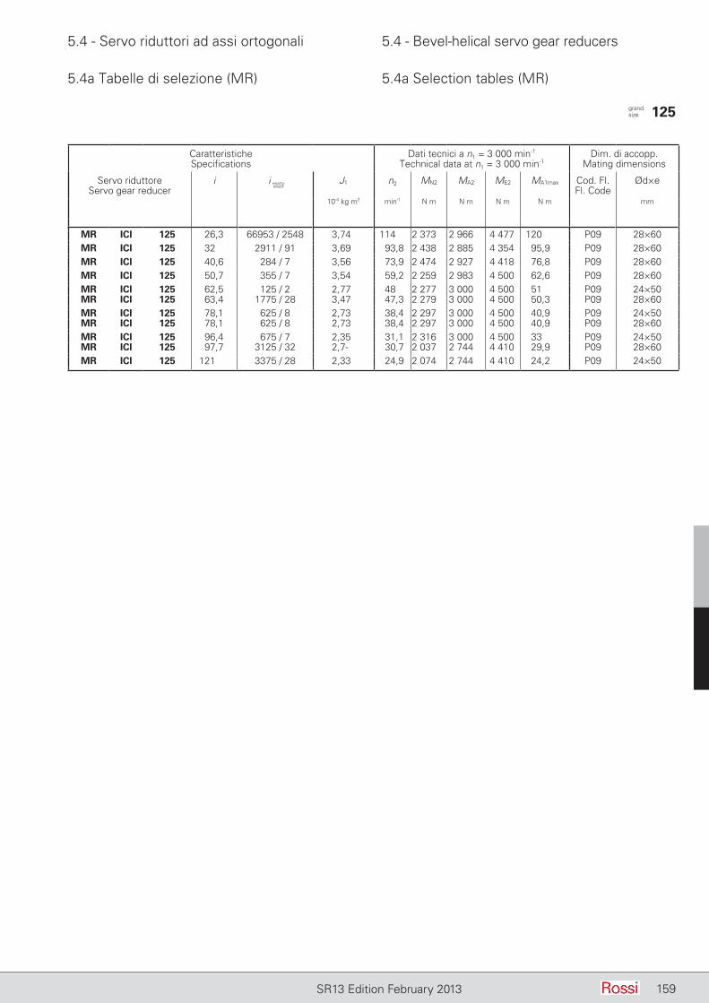
5.4 - Servo riduttori ad assi ortogonali 5.4 - Bevel-helical servo gear reducers
159SR13 Edition February 2013
5.4a Tabelle di selezione (MR) 5.4a Selection tables (MR)
CaratteristicheSpecifications
Dati tecnici a n1 = 3 000 min-1
Technical data at n1 = 3 000 min-1Dim. di accopp.
Mating dimensions
Servo riduttoreServo gear reducer
i J1 n2 MN2 MA2 ME2 MA1max Cod. Fl.Fl. Code
Ød×e
10-4 kg m2 min-1 N m N m N m N m mm
MR ICI 125 26,3 66953 / 2548 3,74 114 2 373 2 966 4 477 120 P09 28×60MR ICI 125 32 2911 / 91 3,69 93,8 2 438 2 885 4 354 95,9 P09 28×60MR ICI 125 40,6 284 / 7 3,56 73,9 2 474 2 927 4 418 76,8 P09 28×60MR ICI 125 50,7 355 / 7 3,54 59,2 2 259 2 983 4 500 62,6 P09 28×60MR ICI 125 62,5 125 / 2 2,77 48 2 277 3 000 4 500 51 P09 24×50MR ICI 125 63,4 1775 / 28 3,47 47,3 2 279 3 000 4 500 50,3 P09 28×60MR ICI 125 78,1 625 / 8 2,73 38,4 2 297 3 000 4 500 40,9 P09 24×50MR ICI 125 78,1 625 / 8 2,73 38,4 2 297 3 000 4 500 40,9 P09 28×60MR ICI 125 96,4 675 / 7 2,35 31,1 2 316 3 000 4 500 33 P09 24×50MR ICI 125 97,7 3125 / 32 2,7- 30,7 2 037 2 744 4 410 29,9 P09 28×60MR ICI 125 121 3375 / 28 2,33 24,9 2 074 2 744 4 410 24,2 P09 24×50
grand. size 125
i esattoexact
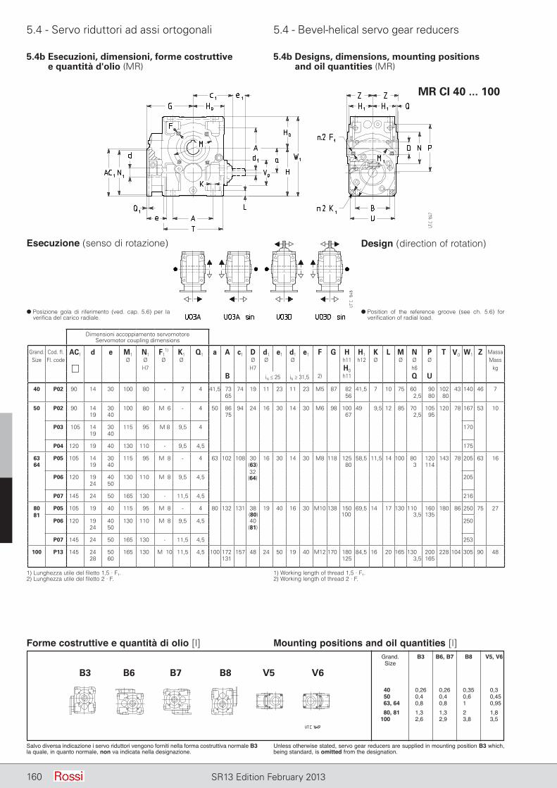
5.4 - Servo riduttori ad assi ortogonali 5.4 - Bevel-helical servo gear reducers
160 SR13 Edition February 2013
MR CI 40 ... 100
5.4b Esecuzioni, dimensioni, forme costruttive e quantità d'olio (MR)
5.4b Designs, dimensions, mounting positions and oil quantities (MR)
1) Lunghezza utile del filetto 1,5 · F1.2) Lunghezza utile del filetto 2 · F.
1) Working length of thread 1,5 · F1.2) Working length of thread 2 · F.
d Posizione gola di riferimento (ved. cap. 5.6) per la verifica del carico radiale.
d Position of the reference groove (see ch. 5.6) for verification of radial load.
Esecuzione (senso di rotazione) Design (direction of rotation)
Forme costruttive e quantità di olio [l]
Salvo diversa indicazione i servo riduttori vengono forniti nella forma costruttiva normale B3 la quale, in quanto normale, non va indicata nella designazione.
Unless otherwise stated, servo gear reducers are supplied in mounting position B3 which, being standard, is omitted from the designation.
Mounting positions and oil quantities [l] Grand. B3 B6, B7 B8 V5, V6 Size
40, 1 0,26 0,26 0,35 0,30 50, 1 0,40 0,40 0,60 0,45 63, 64 0,80 0,80 100, 0,95 80, 81 1,30 1,30 200, 1,80 100, 01 2,60 2,90 3,80 3,50
Dimensioni accoppiamento servomotoreServomotor coupling dimensions
Grand. Cod. fl. AC1 d e M1 N1 F11) K1 Q1 a A c1 D d1 e1 d1 e1 F G H H1 K L M N P T V0 W1 Z Massa
Size Fl. code Ø Ø Ø Ø Ø Ø Ø h11 h12 Ø Ø Ø Ø Mass
H7 H7 H0 h6 kgB iN ≤ 25 iN ≥ 31,5 2) h11 Q U
40 P02 90 14 30 100 80 - 7 4 41,5 73 74 19 11 23 11 23 M5 87 82 41,5 7 10 75 60 90 102 43 140 46 765 56 2,5 80 80
50 P02 90 14 30 100 80 M06 - 4 50 86 94 24 16 30 14 30 M6 98 100 49 9,5 12 85 70 105 120 78 167 53 1019 40 75 67 2,5 95
P03 105 14 30 115 95 M 8 9,5 4 17019 40
P04 120 19 40 130 110 - 9,5 4,5 175
63 P05 105 14 30 115 95 M08 - 4 63 102 108 30 16 30 14 30 M8 118 125 58,5 11,5 14 100 80 120 143 78 205 63 1664 19 40 (63) 80 3 114
P06 120 19 40 130 110 M08 9,5 4,5 20524 50
P07 145 24 50 165 130 - 11,5 4,5 216
80 P05 105 19 40 115 95 M08 - 4 80 132 131 38 19 40 16 30 M10 138 150 69,5 14 17 130 110 160 180 86 250 75 273,5 135
P06 120 19 40 130 110 M08 9,5 4,5 40 25024 50 (81)
P07 145 24 50 165 130 - 11,5 4,5 253
100 P13 145 24 50 165 130 M010 11,5 4,5 100 172 157 48 24 50 19 40 M12 170 180 84,5 16 20 165 130 200 228 104 305 90 4828 60 131 125 3,5 165
(80) 100
B3 B6 B7 B8 V5 V6
81
32(64)
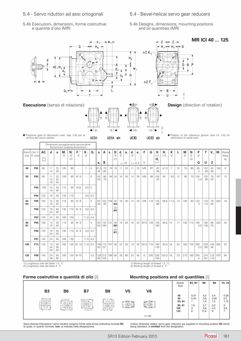
5.4 - Servo riduttori ad assi ortogonali 5.4 - Bevel-helical servo gear reducers
161SR13 Edition February 2013
5.4b Esecuzioni, dimensioni, forme costruttive e quantità d'olio (MR)
5.4b Designs, dimensions, mounting positions and oil quantities (MR)
MR ICI 40 ... 125
1) Lunghezza utile del filetto 1,5 · F12) Lunghezza utile del filetto 2 · F.
1) Working length of thread 1,5 · F1.2) Working length of thread 2 · F.
d Posizione gola di riferimento (ved. cap. 5.6) per la verifica del carico radiale.
d Position of the reference groove (see ch. 5.6) for verification of radial load.
Esecuzione (senso di rotazione) Design (direction of rotation)
Forme costruttive e quantità di olio [l]
Salvo diversa indicazione i servo riduttori vengono forniti nella forma costruttiva normale B3 la quale, in quanto normale, non va indicata nella designazione.
Unless otherwise stated, servo gear reducers are supplied in mounting position B3 which, being standard, is omitted from the designation.
Mounting positions and oil quantities [l] Grand. B3, B7 B6 B8 V5, V6 Size
40, 1 0,31 0,5 0,40 0,35 50, 1 0,45 0,8 0,65 0,50 63, 64 1,00 1,6 1,20 1,15 80, 81 1,60 2,7 2,20 2,00 100, 01 3,00 5,8 4,20 3,80 125, 01 6,00 11,6 9,00 70,0
Dimensioni accoppiamento servomotoreServomotor coupling dimensions
Grand. Cod. fl. AC1 d e M1 N1 F11) K1 Q1 a A c1 D d1 e1 d1 e1 F G H H1 K L M N P T V0 W1 Massa
Size Fl. code Ø Ø Ø Ø Ø Ø Ø h11 h12 Ø Ø Ø Ø Mass
H7 H7 H0 h6 kga1 B iN ≤ 25 iN ≥ 31,5 2) h11 Q U Z
40 P02 90 11 23 100 80 - 7 4 41,5 73 74 19 11 23 11 23 M5 87 82 41,5 7 10 75 60 90 102 43 138 914 30 40 65 56 3 80 46
50 P02 90 11 23 100 80 M06 - 4 63 86 94 24 16 30 14 30 M6 98 100 49 9,5 12 85 70 105 120 78 167 1314 30 50 75 67 2,5 95 5319 40
P03 105 14 30 115 95 M 8 9,5 419 40
P04 120 19 40 130 110 - 9,5 4,5
63 P05 105 14 30 115 95 M08 - 4 63 102 108 30 16 30 14 30 M8 118 125 58,5 11,5 14 100 80 120 143 78 205 1864 19 40 50 90 (63) 80 3 114 63
P06 120 19 40 130 110 M08 9,5 4,524 50
P07 145 24 50 165 130 - 11,5 4,5
80 P05 105 14 30 115 95 M08 - 4 80 132 131 38 19 40 16 30 M10 138 150 69,5 14 17 130 110 160 180 86 250 3081 19 40 50 106 (80) 100 3,5 135 75
P06 120 19 40 130 110 M08 9,5 4,524 50
P07 145 24 50 165 130 - 11,5 4,5
100 P13 145 19 40 165 130 M010 11,5 4,5 100 172 157 48 24 50 19 40 M12 170 180 84,5 16 20 165 130 200 228 104 305 5324 50 63 131 125 3,5 165 9028 60
125 P09 145 24 50 165 130 M 10 - 4,5 125 212 188 60 28 60 24 50 4) 205 225 103,5 18 23 215 180 250 274 122 375 9428 60 80 162 150 4 201 110
B3 B6 B7 B8 V5 V6
32(64)
40(81)
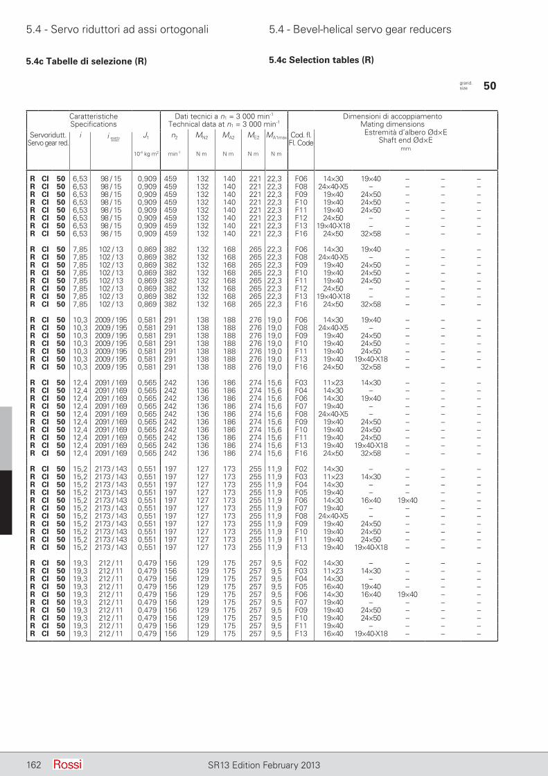
5.4 - Servo riduttori ad assi ortogonali 5.4 - Bevel-helical servo gear reducers
162 SR13 Edition February 2013
5.4c Tabelle di selezione (R) 5.4c Selection tables (R)
CaratteristicheSpecifications
Dati tecnici a n1 = 3 000 min-1
Technical data at n1 = 3 000 min-1Dimensioni di accoppiamento
Mating dimensionsEstremità d’albero Ød×E
Shaft end Ød×Emm
Servoridutt.Servo gear red.
i J1 n2 MN2 MA2 ME2 MA1max Cod. fl.Fl. Code
10-4 kg m2 min-1 N m N m N m N m
R CI 50 6,53 98 / 15 0,909 459 132 140 221 22,3 F06 14×30 19×40 – – –R CI 50 6,53 98 / 15 0,909 459 132 140 221 22,3 F08 24×40-X5 – – – –R CI 50 6,53 98 / 15 0,909 459 132 140 221 22,3 F09 19×40 24×50 – – –R CI 50 6,53 98 / 15 0,909 459 132 140 221 22,3 F10 19×40 24×50 – – –R CI 50 6,53 98 / 15 0,909 459 132 140 221 22,3 F11 19×40 24×50 – – –R CI 50 6,53 98 / 15 0,909 459 132 140 221 22,3 F12 24×50 – – – –R CI 50 6,53 98 / 15 0,909 459 132 140 221 22,3 F13 19×40-X18 – – – –R CI 50 6,53 98 / 15 0,909 459 132 140 221 22,3 F16 24×50 32×58 – – –
R CI 50 7,85 102 / 13 0,869 382 132 168 265 22,3 F06 14×30 19×40 – – –R CI 50 7,85 102 / 13 0,869 382 132 168 265 22,3 F08 24×40-X5 – – – –R CI 50 7,85 102 / 13 0,869 382 132 168 265 22,3 F09 19×40 24×50 – – –R CI 50 7,85 102 / 13 0,869 382 132 168 265 22,3 F10 19×40 24×50 – – –R CI 50 7,85 102 / 13 0,869 382 132 168 265 22,3 F11 19×40 24×50 – – –R CI 50 7,85 102 / 13 0,869 382 132 168 265 22,3 F12 24×50 – – – –R CI 50 7,85 102 / 13 0,869 382 132 168 265 22,3 F13 19×40-X18 – – – –R CI 50 7,85 102 / 13 0,869 382 132 168 265 22,3 F16 24×50 32×58 – – –
R CI 50 10,3 2009 / 195 0,581 291 138 188 276 19,0 F06 14×30 19×40 – – –R CI 50 10,3 2009 / 195 0,581 291 138 188 276 19,0 F08 24×40-X5 – – – –R CI 50 10,3 2009 / 195 0,581 291 138 188 276 19,0 F09 19×40 24×50 – – –R CI 50 10,3 2009 / 195 0,581 291 138 188 276 19,0 F10 19×40 24×50 – – –R CI 50 10,3 2009 / 195 0,581 291 138 188 276 19,0 F11 19×40 24×50 – – –R CI 50 10,3 2009 / 195 0,581 291 138 188 276 19,0 F13 19×40 19×40-X18 – – –R CI 50 10,3 2009 / 195 0,581 291 138 188 276 19,0 F16 24×50 32×58 – – –
R CI 50 12,4 2091 / 169 0,565 242 136 186 274 15,6 F03 11×23 14×30 – – –R CI 50 12,4 2091 / 169 0,565 242 136 186 274 15,6 F04 14×30 – – – –R CI 50 12,4 2091 / 169 0,565 242 136 186 274 15,6 F06 14×30 19×40 – – –R CI 50 12,4 2091 / 169 0,565 242 136 186 274 15,6 F07 19×40 – – – –R CI 50 12,4 2091 / 169 0,565 242 136 186 274 15,6 F08 24×40-X5 – – – –R CI 50 12,4 2091 / 169 0,565 242 136 186 274 15,6 F09 19×40 24×50 – – –R CI 50 12,4 2091 / 169 0,565 242 136 186 274 15,6 F10 19×40 24×50 – – –R CI 50 12,4 2091 / 169 0,565 242 136 186 274 15,6 F11 19×40 24×50 – – –R CI 50 12,4 2091 / 169 0,565 242 136 186 274 15,6 F13 19×40 19×40-X18 – – –R CI 50 12,4 2091 / 169 0,565 242 136 186 274 15,6 F16 24×50 32×58 – – –
R CI 50 15,2 2173 / 143 0,551 197 127 173 255 11,9 F02 14×30 – – – –R CI 50 15,2 2173 / 143 0,551 197 127 173 255 11,9 F03 11×23 14×30 – – –R CI 50 15,2 2173 / 143 0,551 197 127 173 255 11,9 F04 14×30 – – – –R CI 50 15,2 2173 / 143 0,551 197 127 173 255 11,9 F05 19×40 – – – –R CI 50 15,2 2173 / 143 0,551 197 127 173 255 11,9 F06 14×30 16×40 19×40 – –R CI 50 15,2 2173 / 143 0,551 197 127 173 255 11,9 F07 19×40 – – – –R CI 50 15,2 2173 / 143 0,551 197 127 173 255 11,9 F08 24×40-X5 – – – –R CI 50 15,2 2173 / 143 0,551 197 127 173 255 11,9 F09 19×40 24×50 – – –R CI 50 15,2 2173 / 143 0,551 197 127 173 255 11,9 F10 19×40 24×50 – – –R CI 50 15,2 2173 / 143 0,551 197 127 173 255 11,9 F11 19×40 24×50 – – –R CI 50 15,2 2173 / 143 0,551 197 127 173 255 11,9 F13 19×40 19×40-X18 – – –
R CI 50 19,3 212 / 11 0,479 156 129 175 257 9,5 F02 14×30 – – – –R CI 50 19,3 212 / 11 0,479 156 129 175 257 9,5 F03 11×23 14×30 – – –R CI 50 19,3 212 / 11 0,479 156 129 175 257 9,5 F04 14×30 – – – –R CI 50 19,3 212 / 11 0,479 156 129 175 257 9,5 F05 16×40 19×40 – – –R CI 50 19,3 212 / 11 0,479 156 129 175 257 9,5 F06 14×30 16×40 19×40 – –R CI 50 19,3 212 / 11 0,479 156 129 175 257 9,5 F07 19×40 – – – –R CI 50 19,3 212 / 11 0,479 156 129 175 257 9,5 F09 19×40 24×50 – – –R CI 50 19,3 212 / 11 0,479 156 129 175 257 9,5 F10 19×40 24×50 – – –R CI 50 19,3 212 / 11 0,479 156 129 175 257 9,5 F11 19×40 – – – –R CI 50 19,3 212 / 11 0,479 156 129 175 257 9,5 F13 16×40 19×40-X18 – – –
grand. size 50
i esattoexact
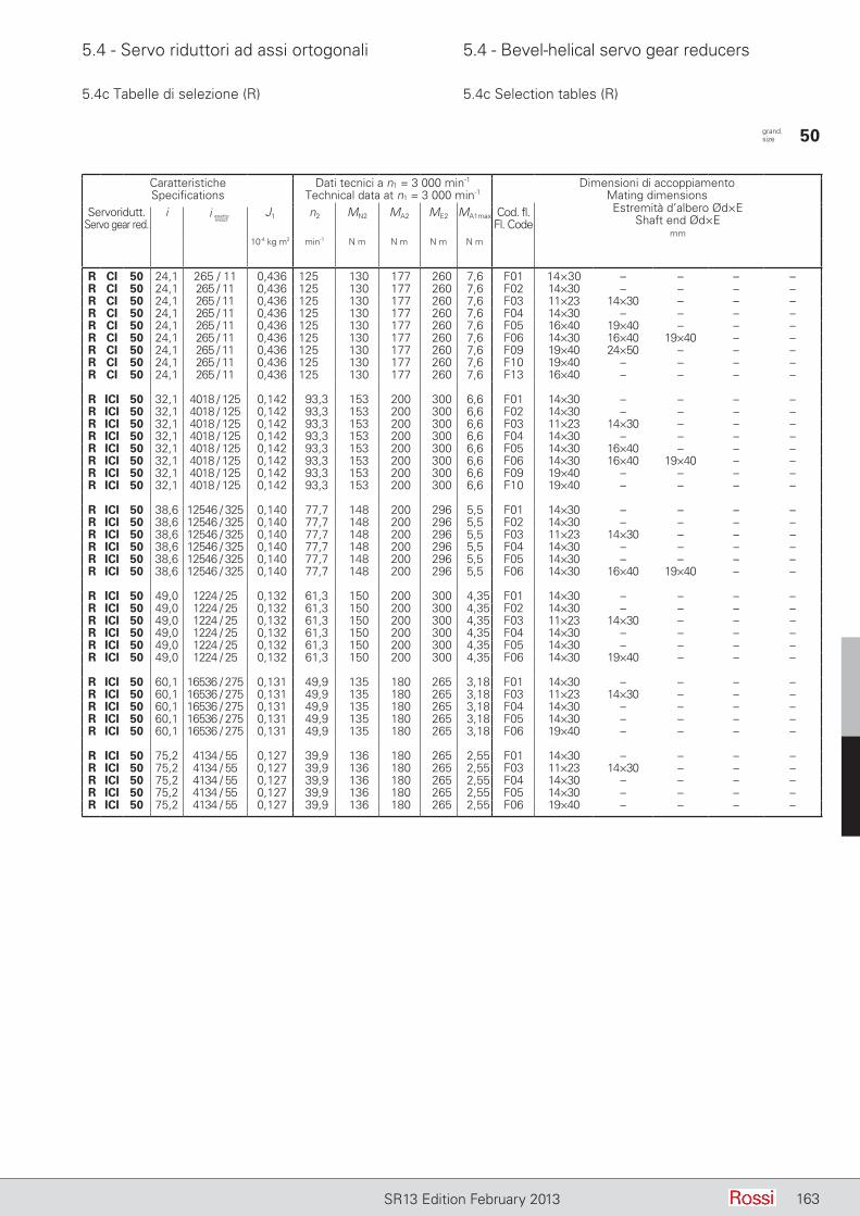
5.4 - Servo riduttori ad assi ortogonali 5.4 - Bevel-helical servo gear reducers
163SR13 Edition February 2013
5.4c Tabelle di selezione (R) 5.4c Selection tables (R)
CaratteristicheSpecifications
Dati tecnici a n1 = 3 000 min-1
Technical data at n1 = 3 000 min-1Dimensioni di accoppiamento
Mating dimensionsEstremità d’albero Ød×E
Shaft end Ød×Emm
Servoridutt.Servo gear red.
i J1 n2 MN2 MA2 ME2 MA1max Cod. fl.Fl. Code
10-4 kg m2 min-1 N m N m N m N m
R CI 50 24,1 265 / 11 0,436 125 130 177 260 7,6 F01 14×30 – – – –R CI 50 24,1 265 / 11 0,436 125 130 177 260 7,6 F02 14×30 – – – –R CI 50 24,1 265 / 11 0,436 125 130 177 260 7,6 F03 11×23 14×30 – – –R CI 50 24,1 265 / 11 0,436 125 130 177 260 7,6 F04 14×30 – – – –R CI 50 24,1 265 / 11 0,436 125 130 177 260 7,6 F05 16×40 19×40 – – –R CI 50 24,1 265 / 11 0,436 125 130 177 260 7,6 F06 14×30 16×40 19×40 – –R CI 50 24,1 265 / 11 0,436 125 130 177 260 7,6 F09 19×40 24×50 – – –R CI 50 24,1 265 / 11 0,436 125 130 177 260 7,6 F10 19×40 – – – –R CI 50 24,1 265 / 11 0,436 125 130 177 260 7,6 F13 16×40 – – – –
R ICI 50 32,1 4018 / 125 0,142 93,3 153 200 300 6,6 F01 14×30 – – – –R ICI 50 32,1 4018 / 125 0,142 93,3 153 200 300 6,6 F02 14×30 – – – –R ICI 50 32,1 4018 / 125 0,142 93,3 153 200 300 6,6 F03 11×23 14×30 – – –R ICI 50 32,1 4018 / 125 0,142 93,3 153 200 300 6,6 F04 14×30 – – – –R ICI 50 32,1 4018 / 125 0,142 93,3 153 200 300 6,6 F05 14×30 16×40 – – –R ICI 50 32,1 4018 / 125 0,142 93,3 153 200 300 6,6 F06 14×30 16×40 19×40 – –R ICI 50 32,1 4018 / 125 0,142 93,3 153 200 300 6,6 F09 19×40 – – – –R ICI 50 32,1 4018 / 125 0,142 93,3 153 200 300 6,6 F10 19×40 – – – –
R ICI 50 38,6 12546 / 325 0,140 77,7 148 200 296 5,5 F01 14×30 – – – –R ICI 50 38,6 12546 / 325 0,140 77,7 148 200 296 5,5 F02 14×30 – – – –R ICI 50 38,6 12546 / 325 0,140 77,7 148 200 296 5,5 F03 11×23 14×30 – – –R ICI 50 38,6 12546 / 325 0,140 77,7 148 200 296 5,5 F04 14×30 – – – –R ICI 50 38,6 12546 / 325 0,140 77,7 148 200 296 5,5 F05 14×30 – – – –R ICI 50 38,6 12546 / 325 0,140 77,7 148 200 296 5,5 F06 14×30 16×40 19×40 – –
R ICI 50 49,0 1224 / 25 0,132 61,3 150 200 300 4,35 F01 14×30 – – – –R ICI 50 49,0 1224 / 25 0,132 61,3 150 200 300 4,35 F02 14×30 – – – –R ICI 50 49,0 1224 / 25 0,132 61,3 150 200 300 4,35 F03 11×23 14×30 – – –R ICI 50 49,0 1224 / 25 0,132 61,3 150 200 300 4,35 F04 14×30 – – – –R ICI 50 49,0 1224 / 25 0,132 61,3 150 200 300 4,35 F05 14×30 – – – –R ICI 50 49,0 1224 / 25 0,132 61,3 150 200 300 4,35 F06 14×30 19×40 – – –
R ICI 50 60,1 16536 / 275 0,131 49,9 135 180 265 3,18 F01 14×30 – – – –R ICI 50 60,1 16536 / 275 0,131 49,9 135 180 265 3,18 F03 11×23 14×30 – – –R ICI 50 60,1 16536 / 275 0,131 49,9 135 180 265 3,18 F04 14×30 – – – –R ICI 50 60,1 16536 / 275 0,131 49,9 135 180 265 3,18 F05 14×30 – – – –R ICI 50 60,1 16536 / 275 0,131 49,9 135 180 265 3,18 F06 19×40 – – – –
R ICI 50 75,2 4134 / 55 0,127 39,9 136 180 265 2,55 F01 14×30 – – – –R ICI 50 75,2 4134 / 55 0,127 39,9 136 180 265 2,55 F03 11×23 14×30 – – –R ICI 50 75,2 4134 / 55 0,127 39,9 136 180 265 2,55 F04 14×30 – – – –R ICI 50 75,2 4134 / 55 0,127 39,9 136 180 265 2,55 F05 14×30 – – – –R ICI 50 75,2 4134 / 55 0,127 39,9 136 180 265 2,55 F06 19×40 – – – –
grand. size 50
i esattoexact
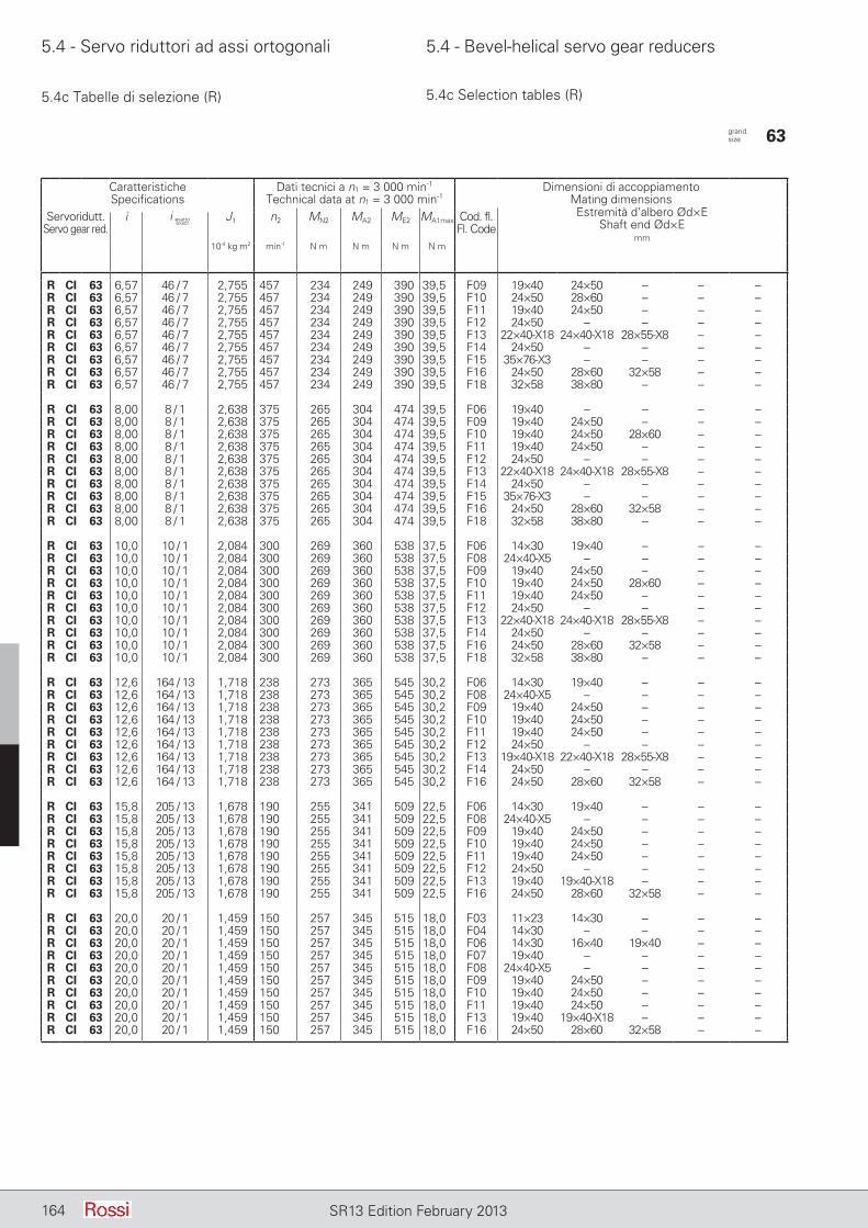
5.4 - Servo riduttori ad assi ortogonali 5.4 - Bevel-helical servo gear reducers
164 SR13 Edition February 2013
5.4c Tabelle di selezione (R) 5.4c Selection tables (R)
CaratteristicheSpecifications
Dati tecnici a n1 = 3 000 min-1
Technical data at n1 = 3 000 min-1Dimensioni di accoppiamento
Mating dimensionsEstremità d’albero Ød×E
Shaft end Ød×Emm
Servoridutt.Servo gear red.
i J1 n2 MN2 MA2 ME2 MA1max Cod. fl.Fl. Code
10-4 kg m2 min-1 N m N m N m N m
R CI 63 6,57 46 / 7 2,755 457 234 249 390 39,5 F09 19×40 24×50 – – –R CI 63 6,57 46 / 7 2,755 457 234 249 390 39,5 F10 24×50 28×60 – – –R CI 63 6,57 46 / 7 2,755 457 234 249 390 39,5 F11 19×40 24×50 – – –R CI 63 6,57 46 / 7 2,755 457 234 249 390 39,5 F12 24×50 – – – –R CI 63 6,57 46 / 7 2,755 457 234 249 390 39,5 F13 22×40-X18 24×40-X18 28×55-X8 – –R CI 63 6,57 46 / 7 2,755 457 234 249 390 39,5 F14 24×50 – – – –R CI 63 6,57 46 / 7 2,755 457 234 249 390 39,5 F15 35×76-X3 – – – –R CI 63 6,57 46 / 7 2,755 457 234 249 390 39,5 F16 24×50 28×60 32×58 – –R CI 63 6,57 46 / 7 2,755 457 234 249 390 39,5 F18 32×58 38×80 – – –
R CI 63 8,00 8 / 1 2,638 375 265 304 474 39,5 F06 19×40 – – – –R CI 63 8,00 8 / 1 2,638 375 265 304 474 39,5 F09 19×40 24×50 – – –R CI 63 8,00 8 / 1 2,638 375 265 304 474 39,5 F10 19×40 24×50 28×60 – –R CI 63 8,00 8 / 1 2,638 375 265 304 474 39,5 F11 19×40 24×50 – – –R CI 63 8,00 8 / 1 2,638 375 265 304 474 39,5 F12 24×50 – – – –R CI 63 8,00 8 / 1 2,638 375 265 304 474 39,5 F13 22×40-X18 24×40-X18 28×55-X8 – –R CI 63 8,00 8 / 1 2,638 375 265 304 474 39,5 F14 24×50 – – – –R CI 63 8,00 8 / 1 2,638 375 265 304 474 39,5 F15 35×76-X3 – – – –R CI 63 8,00 8 / 1 2,638 375 265 304 474 39,5 F16 24×50 28×60 32×58 – –R CI 63 8,00 8 / 1 2,638 375 265 304 474 39,5 F18 32×58 38×80 – – –
R CI 63 10,0 10 / 1 2,084 300 269 360 538 37,5 F06 14×30 19×40 – – –R CI 63 10,0 10 / 1 2,084 300 269 360 538 37,5 F08 24×40-X5 – – – –R CI 63 10,0 10 / 1 2,084 300 269 360 538 37,5 F09 19×40 24×50 – – –R CI 63 10,0 10 / 1 2,084 300 269 360 538 37,5 F10 19×40 24×50 28×60 – –R CI 63 10,0 10 / 1 2,084 300 269 360 538 37,5 F11 19×40 24×50 – – –R CI 63 10,0 10 / 1 2,084 300 269 360 538 37,5 F12 24×50 – – – –R CI 63 10,0 10 / 1 2,084 300 269 360 538 37,5 F13 22×40-X18 24×40-X18 28×55-X8 – –R CI 63 10,0 10 / 1 2,084 300 269 360 538 37,5 F14 24×50 – – – –R CI 63 10,0 10 / 1 2,084 300 269 360 538 37,5 F16 24×50 28×60 32×58 – –R CI 63 10,0 10 / 1 2,084 300 269 360 538 37,5 F18 32×58 38×80 – – –
R CI 63 12,6 164 / 13 1,718 238 273 365 545 30,2 F06 14×30 19×40 – – –R CI 63 12,6 164 / 13 1,718 238 273 365 545 30,2 F08 24×40-X5 – – – –R CI 63 12,6 164 / 13 1,718 238 273 365 545 30,2 F09 19×40 24×50 – – –R CI 63 12,6 164 / 13 1,718 238 273 365 545 30,2 F10 19×40 24×50 – – –R CI 63 12,6 164 / 13 1,718 238 273 365 545 30,2 F11 19×40 24×50 – – –R CI 63 12,6 164 / 13 1,718 238 273 365 545 30,2 F12 24×50 – – – –R CI 63 12,6 164 / 13 1,718 238 273 365 545 30,2 F13 19×40-X18 22×40-X18 28×55-X8 – –R CI 63 12,6 164 / 13 1,718 238 273 365 545 30,2 F14 24×50 – – – –R CI 63 12,6 164 / 13 1,718 238 273 365 545 30,2 F16 24×50 28×60 32×58 – –
R CI 63 15,8 205 / 13 1,678 190 255 341 509 22,5 F06 14×30 19×40 – – –R CI 63 15,8 205 / 13 1,678 190 255 341 509 22,5 F08 24×40-X5 – – – –R CI 63 15,8 205 / 13 1,678 190 255 341 509 22,5 F09 19×40 24×50 – – –R CI 63 15,8 205 / 13 1,678 190 255 341 509 22,5 F10 19×40 24×50 – – –R CI 63 15,8 205 / 13 1,678 190 255 341 509 22,5 F11 19×40 24×50 – – –R CI 63 15,8 205 / 13 1,678 190 255 341 509 22,5 F12 24×50 – – – –R CI 63 15,8 205 / 13 1,678 190 255 341 509 22,5 F13 19×40 19×40-X18 – – –R CI 63 15,8 205 / 13 1,678 190 255 341 509 22,5 F16 24×50 28×60 32×58 – –
R CI 63 20,0 20 / 1 1,459 150 257 345 515 18,0 F03 11×23 14×30 – – –R CI 63 20,0 20 / 1 1,459 150 257 345 515 18,0 F04 14×30 – – – –R CI 63 20,0 20 / 1 1,459 150 257 345 515 18,0 F06 14×30 16×40 19×40 – –R CI 63 20,0 20 / 1 1,459 150 257 345 515 18,0 F07 19×40 – – – –R CI 63 20,0 20 / 1 1,459 150 257 345 515 18,0 F08 24×40-X5 – – – –R CI 63 20,0 20 / 1 1,459 150 257 345 515 18,0 F09 19×40 24×50 – – –R CI 63 20,0 20 / 1 1,459 150 257 345 515 18,0 F10 19×40 24×50 – – –R CI 63 20,0 20 / 1 1,459 150 257 345 515 18,0 F11 19×40 24×50 – – –R CI 63 20,0 20 / 1 1,459 150 257 345 515 18,0 F13 19×40 19×40-X18 – – –R CI 63 20,0 20 / 1 1,459 150 257 345 515 18,0 F16 24×50 28×60 32×58 – –
grand. size 63
i esattoexact
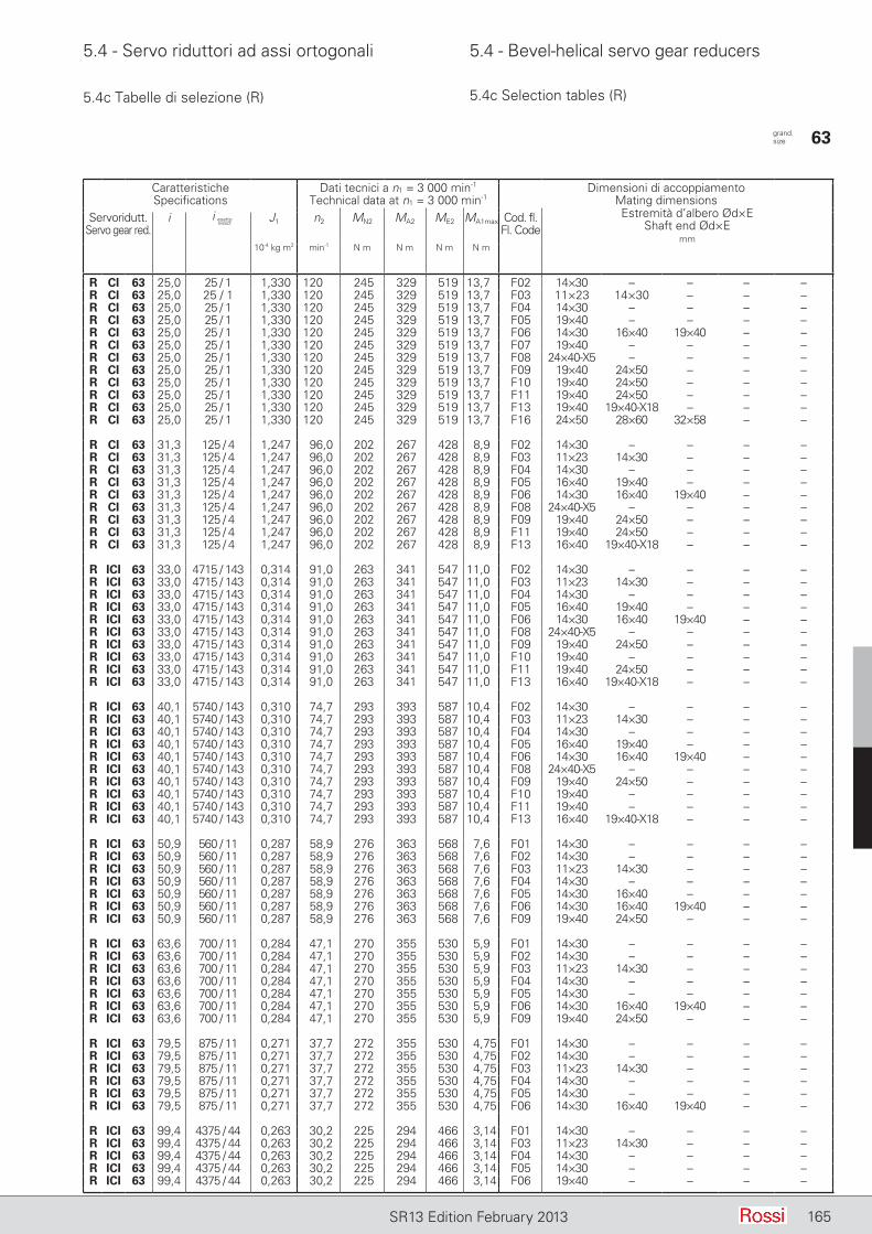
5.4 - Servo riduttori ad assi ortogonali 5.4 - Bevel-helical servo gear reducers
165SR13 Edition February 2013
5.4c Tabelle di selezione (R) 5.4c Selection tables (R)
CaratteristicheSpecifications
Dati tecnici a n1 = 3 000 min-1
Technical data at n1 = 3 000 min-1Dimensioni di accoppiamento
Mating dimensionsEstremità d’albero Ød×E
Shaft end Ød×Emm
Servoridutt.Servo gear red.
i J1 n2 MN2 MA2 ME2 MA1max Cod. fl.Fl. Code
10-4 kg m2 min-1 N m N m N m N m
R CI 63 25,0 25 / 1 1,330 120 245 329 519 13,7 F02 14×30 – – – –R CI 63 25,0 25 / 1 1,330 120 245 329 519 13,7 F03 11×23 14×30 – – –R CI 63 25,0 25 / 1 1,330 120 245 329 519 13,7 F04 14×30 – – – –R CI 63 25,0 25 / 1 1,330 120 245 329 519 13,7 F05 19×40 – – – –R CI 63 25,0 25 / 1 1,330 120 245 329 519 13,7 F06 14×30 16×40 19×40 – –R CI 63 25,0 25 / 1 1,330 120 245 329 519 13,7 F07 19×40 – – – –R CI 63 25,0 25 / 1 1,330 120 245 329 519 13,7 F08 24×40-X5 – – – –R CI 63 25,0 25 / 1 1,330 120 245 329 519 13,7 F09 19×40 24×50 – – –R CI 63 25,0 25 / 1 1,330 120 245 329 519 13,7 F10 19×40 24×50 – – –R CI 63 25,0 25 / 1 1,330 120 245 329 519 13,7 F11 19×40 24×50 – – –R CI 63 25,0 25 / 1 1,330 120 245 329 519 13,7 F13 19×40 19×40-X18 – – –R CI 63 25,0 25 / 1 1,330 120 245 329 519 13,7 F16 24×50 28×60 32×58 – –
R CI 63 31,3 125 / 4 1,247 96,0 202 267 428 8,9 F02 14×30 – – – –R CI 63 31,3 125 / 4 1,247 96,0 202 267 428 8,9 F03 11×23 14×30 – – –R CI 63 31,3 125 / 4 1,247 96,0 202 267 428 8,9 F04 14×30 – – – –R CI 63 31,3 125 / 4 1,247 96,0 202 267 428 8,9 F05 16×40 19×40 – – –R CI 63 31,3 125 / 4 1,247 96,0 202 267 428 8,9 F06 14×30 16×40 19×40 – –R CI 63 31,3 125 / 4 1,247 96,0 202 267 428 8,9 F08 24×40-X5 – – – –R CI 63 31,3 125 / 4 1,247 96,0 202 267 428 8,9 F09 19×40 24×50 – – –R CI 63 31,3 125 / 4 1,247 96,0 202 267 428 8,9 F11 19×40 24×50 – – –R CI 63 31,3 125 / 4 1,247 96,0 202 267 428 8,9 F13 16×40 19×40-X18 – – –
R ICI 63 33,0 4715 / 143 0,314 91,0 263 341 547 11,0 F02 14×30 – – – –R ICI 63 33,0 4715 / 143 0,314 91,0 263 341 547 11,0 F03 11×23 14×30 – – –R ICI 63 33,0 4715 / 143 0,314 91,0 263 341 547 11,0 F04 14×30 – – – –R ICI 63 33,0 4715 / 143 0,314 91,0 263 341 547 11,0 F05 16×40 19×40 – – –R ICI 63 33,0 4715 / 143 0,314 91,0 263 341 547 11,0 F06 14×30 16×40 19×40 – –R ICI 63 33,0 4715 / 143 0,314 91,0 263 341 547 11,0 F08 24×40-X5 – – – –R ICI 63 33,0 4715 / 143 0,314 91,0 263 341 547 11,0 F09 19×40 24×50 – – –R ICI 63 33,0 4715 / 143 0,314 91,0 263 341 547 11,0 F10 19×40 – – – –R ICI 63 33,0 4715 / 143 0,314 91,0 263 341 547 11,0 F11 19×40 24×50 – – –R ICI 63 33,0 4715 / 143 0,314 91,0 263 341 547 11,0 F13 16×40 19×40-X18 – – –
R ICI 63 40,1 5740 / 143 0,310 74,7 293 393 587 10,4 F02 14×30 – – – –R ICI 63 40,1 5740 / 143 0,310 74,7 293 393 587 10,4 F03 11×23 14×30 – – –R ICI 63 40,1 5740 / 143 0,310 74,7 293 393 587 10,4 F04 14×30 – – – –R ICI 63 40,1 5740 / 143 0,310 74,7 293 393 587 10,4 F05 16×40 19×40 – – –R ICI 63 40,1 5740 / 143 0,310 74,7 293 393 587 10,4 F06 14×30 16×40 19×40 – –R ICI 63 40,1 5740 / 143 0,310 74,7 293 393 587 10,4 F08 24×40-X5 – – – –R ICI 63 40,1 5740 / 143 0,310 74,7 293 393 587 10,4 F09 19×40 24×50 – – –R ICI 63 40,1 5740 / 143 0,310 74,7 293 393 587 10,4 F10 19×40 – – – –R ICI 63 40,1 5740 / 143 0,310 74,7 293 393 587 10,4 F11 19×40 – – – –R ICI 63 40,1 5740 / 143 0,310 74,7 293 393 587 10,4 F13 16×40 19×40-X18 – – –
R ICI 63 50,9 560 / 11 0,287 58,9 276 363 568 7,6 F01 14×30 – – – –R ICI 63 50,9 560 / 11 0,287 58,9 276 363 568 7,6 F02 14×30 – – – –R ICI 63 50,9 560 / 11 0,287 58,9 276 363 568 7,6 F03 11×23 14×30 – – –R ICI 63 50,9 560 / 11 0,287 58,9 276 363 568 7,6 F04 14×30 – – – –R ICI 63 50,9 560 / 11 0,287 58,9 276 363 568 7,6 F05 14×30 16×40 – – –R ICI 63 50,9 560 / 11 0,287 58,9 276 363 568 7,6 F06 14×30 16×40 19×40 – –R ICI 63 50,9 560 / 11 0,287 58,9 276 363 568 7,6 F09 19×40 24×50 – – –
R ICI 63 63,6 700 / 11 0,284 47,1 270 355 530 5,9 F01 14×30 – – – –R ICI 63 63,6 700 / 11 0,284 47,1 270 355 530 5,9 F02 14×30 – – – –R ICI 63 63,6 700 / 11 0,284 47,1 270 355 530 5,9 F03 11×23 14×30 – – –R ICI 63 63,6 700 / 11 0,284 47,1 270 355 530 5,9 F04 14×30 – – – –R ICI 63 63,6 700 / 11 0,284 47,1 270 355 530 5,9 F05 14×30 – – – –R ICI 63 63,6 700 / 11 0,284 47,1 270 355 530 5,9 F06 14×30 16×40 19×40 – –R ICI 63 63,6 700 / 11 0,284 47,1 270 355 530 5,9 F09 19×40 24×50 – – –
R ICI 63 79,5 875 / 11 0,271 37,7 272 355 530 4,75 F01 14×30 – – – –R ICI 63 79,5 875 / 11 0,271 37,7 272 355 530 4,75 F02 14×30 – – – –R ICI 63 79,5 875 / 11 0,271 37,7 272 355 530 4,75 F03 11×23 14×30 – – –R ICI 63 79,5 875 / 11 0,271 37,7 272 355 530 4,75 F04 14×30 – – – –R ICI 63 79,5 875 / 11 0,271 37,7 272 355 530 4,75 F05 14×30 – – – –R ICI 63 79,5 875 / 11 0,271 37,7 272 355 530 4,75 F06 14×30 16×40 19×40 – –
R ICI 63 99,4 4375 / 44 0,263 30,2 225 294 466 3,14 F01 14×30 – – – –R ICI 63 99,4 4375 / 44 0,263 30,2 225 294 466 3,14 F03 11×23 14×30 – – –R ICI 63 99,4 4375 / 44 0,263 30,2 225 294 466 3,14 F04 14×30 – – – –R ICI 63 99,4 4375 / 44 0,263 30,2 225 294 466 3,14 F05 14×30 – – – –R ICI 63 99,4 4375 / 44 0,263 30,2 225 294 466 3,14 F06 19×40 – – – –
grand. size 63
i esattoexact

5.4 - Servo riduttori ad assi ortogonali 5.4 - Bevel-helical servo gear reducers
166 SR13 Edition February 2013
5.4c Tabelle di selezione (R) 5.4c Selection tables (R)
CaratteristicheSpecifications
Dati tecnici a n1 = 3 000 min-1
Technical data at n1 = 3 000 min-1Dimensioni di accoppiamento
Mating dimensionsEstremità d’albero Ød×E
Shaft end Ød×Emm
Servoridutt.Servo gear red.
i J1 n2 MN2 MA2 ME2 MA1max Cod. fl.Fl. Code
10-4 kg m2 min-1 N m N m N m N m
R CI 64 6,57 46 / 7 2,824 457 298 314 502 49,7 F09 19×40 24×50 – – –R CI 64 6,57 46 / 7 2,824 457 298 314 502 49,7 F10 24×50 28×60 – – –R CI 64 6,57 46 / 7 2,824 457 298 314 502 49,7 F11 24×50 – – – –R CI 64 6,57 46 / 7 2,824 457 298 314 502 49,7 F13 24×40-X18 28×55-X8 – – –R CI 64 6,57 46 / 7 2,824 457 298 314 502 49,7 F14 24×50 – – – –R CI 64 6,57 46 / 7 2,824 457 298 314 502 49,7 F15 35×76-X3 – – – –R CI 64 6,57 46 / 7 2,824 457 298 314 502 49,7 F16 24×50 28×60 32×58 – –R CI 64 6,57 46 / 7 2,824 457 298 314 502 49,7 F17 32×60 – – – –R CI 64 6,57 46 / 7 2,824 457 298 314 502 49,7 F18 24×50 32×58 38×80 – –
R CI 64 8,00 8 / 1 2,684 375 300 382 600 49,7 F09 19×40 24×50 – – –R CI 64 8,00 8 / 1 2,684 375 300 382 600 49,7 F10 24×50 28×60 – – –R CI 64 8,00 8 / 1 2,684 375 300 382 600 49,7 F11 24×50 – – – –R CI 64 8,00 8 / 1 2,684 375 300 382 600 49,7 F12 24×50 – – – –R CI 64 8,00 8 / 1 2,684 375 300 382 600 49,7 F13 22×40-X18 24×40-X18 28×55-X8 – –R CI 64 8,00 8 / 1 2,684 375 300 382 600 49,7 F14 24×50 – – – –R CI 64 8,00 8 / 1 2,684 375 300 382 600 49,7 F15 35×76-X3 – – – –R CI 64 8,00 8 / 1 2,684 375 300 382 600 49,7 F16 24×50 28×60 32×58 – –R CI 64 8,00 8 / 1 2,684 375 300 382 600 49,7 F17 32×60 – – – –R CI 64 8,00 8 / 1 2,684 375 300 382 600 49,7 F18 24×50 32×58 38×80 – –
R CI 64 10,0 10 / 1 2,114 300 305 407 611 42,4 F09 19×40 24×50 – – –R CI 64 10,0 10 / 1 2,114 300 305 407 611 42,4 F10 24×50 28×60 – – –R CI 64 10,0 10 / 1 2,114 300 305 407 611 42,4 F11 19×40 24×50 – – –R CI 64 10,0 10 / 1 2,114 300 305 407 611 42,4 F12 24×50 – – – –R CI 64 10,0 10 / 1 2,114 300 305 407 611 42,4 F13 22×40-X18 24×40-X18 28×55-X8 – –R CI 64 10,0 10 / 1 2,114 300 305 407 611 42,4 F14 24×50 – – – –R CI 64 10,0 10 / 1 2,114 300 305 407 611 42,4 F16 24×50 28×60 32×58 – –R CI 64 10,0 10 / 1 2,114 300 305 407 611 42,4 F17 32×60 – – – –R CI 64 10,0 10 / 1 2,114 300 305 407 611 42,4 F18 24×50 32×58 38×80 – –
R CI 64 12,6 164 / 13 1,737 238 311 415 623 34,3 F06 19×40 – – – –R CI 64 12,6 164 / 13 1,737 238 311 415 623 34,3 F08 24×40-X5 – – – –R CI 64 12,6 164 / 13 1,737 238 311 415 623 34,3 F09 19×40 24×50 – – –R CI 64 12,6 164 / 13 1,737 238 311 415 623 34,3 F10 24×50 28×60 – – –R CI 64 12,6 164 / 13 1,737 238 311 415 623 34,3 F11 19×40 24×50 – – –R CI 64 12,6 164 / 13 1,737 238 311 415 623 34,3 F12 24×50 – – – –R CI 64 12,6 164 / 13 1,737 238 311 415 623 34,3 F13 22×40-X18 24×40-X18 28×55-X8 – –R CI 64 12,6 164 / 13 1,737 238 311 415 623 34,3 F14 24×50 – – – –R CI 64 12,6 164 / 13 1,737 238 311 415 623 34,3 F16 24×50 28×60 32×58 – –R CI 64 12,6 164 / 13 1,737 238 311 415 623 34,3 F18 32×58 – – – –
R CI 64 15,8 205 / 13 1,690 190 288 386 577 25,5 F06 14×30 19×40 – – –R CI 64 15,8 205 / 13 1,690 190 288 386 577 25,5 F08 24×40-X5 – – – –R CI 64 15,8 205 / 13 1,690 190 288 386 577 25,5 F09 19×40 24×50 – – –R CI 64 15,8 205 / 13 1,690 190 288 386 577 25,5 F10 19×40 24×50 – – –R CI 64 15,8 205 / 13 1,690 190 288 386 577 25,5 F11 19×40 24×50 – – –R CI 64 15,8 205 / 13 1,690 190 288 386 577 25,5 F12 24×50 – – – –R CI 64 15,8 205 / 13 1,690 190 288 386 577 25,5 F13 22×40-X18 28×55-X8 – – –R CI 64 15,8 205 / 13 1,690 190 288 386 577 25,5 F14 24×50 – – – –R CI 64 15,8 205 / 13 1,690 190 288 386 577 25,5 F16 24×50 28×60 32×58 – –
R CI 64 20,0 20 / 1 1,467 150 293 392 586 20,4 F06 14×30 19×40 – – –R CI 64 20,0 20 / 1 1,467 150 293 392 586 20,4 F08 24×40-X5 – – – –R CI 64 20,0 20 / 1 1,467 150 293 392 586 20,4 F09 19×40 24×50 – – –R CI 64 20,0 20 / 1 1,467 150 293 392 586 20,4 F10 19×40 24×50 – – –R CI 64 20,0 20 / 1 1,467 150 293 392 586 20,4 F11 19×40 24×50 – – –R CI 64 20,0 20 / 1 1,467 150 293 392 586 20,4 F12 24×50 – – – –R CI 64 20,0 20 / 1 1,467 150 293 392 586 20,4 F13 19×40 19×40-X18 – – –R CI 64 20,0 20 / 1 1,467 150 293 392 586 20,4 F16 24×50 28×60 32×58 – –
R CI 64 25,0 25 / 1 1,335 120 297 398 595 16,6 F03 11×23 14×30 – – –R CI 64 25,0 25 / 1 1,335 120 297 398 595 16,6 F04 14×30 – – – –R CI 64 25,0 25 / 1 1,335 120 297 398 595 16,6 F06 14×30 16×40 19×40 – –R CI 64 25,0 25 / 1 1,335 120 297 398 595 16,6 F07 19×40 – – – –R CI 64 25,0 25 / 1 1,335 120 297 398 595 16,6 F08 24×40-X5 – – – –R CI 64 25,0 25 / 1 1,335 120 297 398 595 16,6 F09 19×40 24×50 – – –R CI 64 25,0 25 / 1 1,335 120 297 398 595 16,6 F10 19×40 24×50 – – –R CI 64 25,0 25 / 1 1,335 120 297 398 595 16,6 F11 19×40 24×50 – – –R CI 64 25,0 25 / 1 1,335 120 297 398 595 16,6 F13 19×40 19×40-X18 – – –R CI 64 25,0 25 / 1 1,335 120 297 398 595 16,6 F16 24×50 28×60 32×58 – –
grand. size 64
i esattoexact
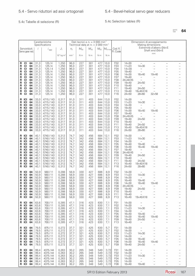
5.4 - Servo riduttori ad assi ortogonali 5.4 - Bevel-helical servo gear reducers
167SR13 Edition February 2013
5.4c Tabelle di selezione (R) 5.4c Selection tables (R)
CaratteristicheSpecifications
Dati tecnici a n1 = 3 000 min-1
Technical data at n1 = 3 000 min-1Dimensioni di accoppiamento
Mating dimensionsEstremità d’albero Ød×E
Shaft end Ød×Emm
Servoridutt.Servo gear red.
i J1 n2 MN2 MA2 ME2 MA1max Cod. fl.Fl. Code
10-4 kg m2 min-1 N m N m N m N m
R CI 64 31,3 125 / 4 1,250 96,0 227 301 477 10,0 F02 14×30 – – – –R CI 64 31,3 125 / 4 1,250 96,0 227 301 477 10,0 F03 11×23 14×30 – – –R CI 64 31,3 125 / 4 1,250 96,0 227 301 477 10,0 F04 14×30 – – – –R CI 64 31,3 125 / 4 1,250 96,0 227 301 477 10,0 F05 19×40 – – – –R CI 64 31,3 125 / 4 1,250 96,0 227 301 477 10,0 F06 14×30 16×40 19×40 – –R CI 64 31,3 125 / 4 1,250 96,0 227 301 477 10,0 F07 19×40 – – – –R CI 64 31,3 125 / 4 1,250 96,0 227 301 477 10,0 F08 24×40-X5 – – – –R CI 64 31,3 125 / 4 1,250 96,0 227 301 477 10,0 F09 19×40 24×50 – – –R CI 64 31,3 125 / 4 1,250 96,0 227 301 477 10,0 F10 19×40 – – – –R CI 64 31,3 125 / 4 1,250 96,0 227 301 477 10,0 F11 19×40 24×50 – – –R CI 64 31,3 125 / 4 1,250 96,0 227 301 477 10,0 F13 19×40 19×40-X18 – – –R CI 64 31,3 125 / 4 1,250 96,0 227 301 477 10,0 F16 24×50 28×60 32×58 – –
R ICI 64 33,0 4715 / 143 0,317 91,0 311 403 644 13,0 F02 14×30 – – – –R ICI 64 33,0 4715 / 143 0,317 91,0 311 403 644 13,0 F03 11×23 14×30 – – –R ICI 64 33,0 4715 / 143 0,317 91,0 311 403 644 13,0 F04 14×30 – – – –R ICI 64 33,0 4715 / 143 0,317 91,0 311 403 644 13,0 F05 19×40 – – – –R ICI 64 33,0 4715 / 143 0,317 91,0 311 403 644 13,0 F06 14×30 16×40 19×40 – –R ICI 64 33,0 4715 / 143 0,317 91,0 311 403 644 13,0 F07 19×40 – – – –R ICI 64 33,0 4715 / 143 0,317 91,0 311 403 644 13,0 F08 24×40-X5 – – – –R ICI 64 33,0 4715 / 143 0,317 91,0 311 403 644 13,0 F09 19×40 24×50 – – –R ICI 64 33,0 4715 / 143 0,317 91,0 311 403 644 13,0 F10 19×40 – – – –R ICI 64 33,0 4715 / 143 0,317 91,0 311 403 644 13,0 F11 19×40 24×50 – – –R ICI 64 33,0 4715 / 143 0,317 91,0 311 403 644 13,0 F13 16×40 19×40-X18 – – –R ICI 64 33,0 4715 / 143 0,317 91,0 311 403 644 13,0 F16 24×50 28×60 – – –
R ICI 64 40,1 5740 / 143 0,312 74,7 342 456 684 12,1 F02 14×30 – – – –R ICI 64 40,1 5740 / 143 0,312 74,7 342 456 684 12,1 F03 11×23 14×30 – – –R ICI 64 40,1 5740 / 143 0,312 74,7 342 456 684 12,1 F04 14×30 – – – –R ICI 64 40,1 5740 / 143 0,312 74,7 342 456 684 12,1 F05 16×40 19×40 – – –R ICI 64 40,1 5740 / 143 0,312 74,7 342 456 684 12,1 F06 14×30 16×40 19×40 – –R ICI 64 40,1 5740 / 143 0,312 74,7 342 456 684 12,1 F07 19×40 – – – –R ICI 64 40,1 5740 / 143 0,312 74,7 342 456 684 12,1 F08 24×40-X5 – – – –R ICI 64 40,1 5740 / 143 0,312 74,7 342 456 684 12,1 F09 19×40 24×50 – – –R ICI 64 40,1 5740 / 143 0,312 74,7 342 456 684 12,1 F10 19×40 – – – –R ICI 64 40,1 5740 / 143 0,312 74,7 342 456 684 12,1 F11 19×40 24×50 – – –R ICI 64 40,1 5740 / 143 0,312 74,7 342 456 684 12,1 F13 16×40 19×40-X18 – – –R ICI 64 40,1 5740 / 143 0,312 74,7 342 456 684 12,1 F16 24×50 28×60 – – –
R ICI 64 50,9 560 / 11 0,288 58,9 330 427 686 8,9 F02 14×30 – – – –R ICI 64 50,9 560 / 11 0,288 58,9 330 427 686 8,9 F03 11×23 14×30 – – –R ICI 64 50,9 560 / 11 0,288 58,9 330 427 686 8,9 F04 14×30 – – – –R ICI 64 50,9 560 / 11 0,288 58,9 330 427 686 8,9 F05 16×40 19×40 – – –R ICI 64 50,9 560 / 11 0,288 58,9 330 427 686 8,9 F06 14×30 16×40 19×40 – –R ICI 64 50,9 560 / 11 0,288 58,9 330 427 686 8,9 F08 24×40-X5 – – – –R ICI 64 50,9 560 / 11 0,288 58,9 330 427 686 8,9 F09 19×40 24×50 – – –R ICI 64 50,9 560 / 11 0,288 58,9 330 427 686 8,9 F10 19×40 – – – –R ICI 64 50,9 560 / 11 0,288 58,9 330 427 686 8,9 F11 19×40 – – – –R ICI 64 50,9 560 / 11 0,288 58,9 330 427 686 8,9 F13 16×40 19×40-X18 – – –
R ICI 64 63,6 700 / 11 0,285 47,1 316 423 630 7,1 F01 14×30 – – – –R ICI 64 63,6 700 / 11 0,285 47,1 316 423 630 7,1 F02 14×30 – – – –R ICI 64 63,6 700 / 11 0,285 47,1 316 423 630 7,1 F03 11×23 14×30 – – –R ICI 64 63,6 700 / 11 0,285 47,1 316 423 630 7,1 F04 14×30 – – – –R ICI 64 63,6 700 / 11 0,285 47,1 316 423 630 7,1 F05 16×40 19×40 – – –R ICI 64 63,6 700 / 11 0,285 47,1 316 423 630 7,1 F06 14×30 16×40 19×40 – –R ICI 64 63,6 700 / 11 0,285 47,1 316 423 630 7,1 F09 19×40 24×50 – – –R ICI 64 63,6 700 / 11 0,285 47,1 316 423 630 7,1 F13 16×40 – – – –
R ICI 64 79,5 875 / 11 0,272 37,7 321 425 630 5,7 F01 14×30 – – – –R ICI 64 79,5 875 / 11 0,272 37,7 321 425 630 5,7 F02 14×30 – – – –R ICI 64 79,5 875 / 11 0,272 37,7 321 425 630 5,7 F03 11×23 14×30 – – –R ICI 64 79,5 875 / 11 0,272 37,7 321 425 630 5,7 F04 14×30 – – – –R ICI 64 79,5 875 / 11 0,272 37,7 321 425 630 5,7 F05 14×30 16×40 – – –R ICI 64 79,5 875 / 11 0,272 37,7 321 425 630 5,7 F06 14×30 16×40 19×40 – –R ICI 64 79,5 875 / 11 0,272 37,7 321 425 630 5,7 F09 19×40 24×50 – – –
R ICI 64 99,4 4375 / 44 0,263 30,2 265 348 549 3,72 F01 14×30 – – – –R ICI 64 99,4 4375 / 44 0,263 30,2 265 348 549 3,72 F02 14×30 – – – –R ICI 64 99,4 4375 / 44 0,263 30,2 265 348 549 3,72 F03 11×23 14×30 – – –R ICI 64 99,4 4375 / 44 0,263 30,2 265 348 549 3,72 F04 14×30 – – – –R ICI 64 99,4 4375 / 44 0,263 30,2 265 348 549 3,72 F05 14×30 – – – –R ICI 64 99,4 4375 / 44 0,263 30,2 265 348 549 3,72 F06 16×40 19×40 – – –
grand. size 64
i esattoexact
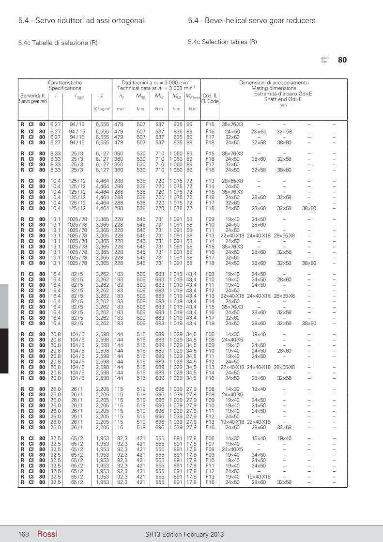
5.4 - Servo riduttori ad assi ortogonali 5.4 - Bevel-helical servo gear reducers
168 SR13 Edition February 2013
5.4c Tabelle di selezione (R) 5.4c Selection tables (R)
CaratteristicheSpecifications
Dati tecnici a n1 = 3 000 min-1
Technical data at n1 = 3 000 min-1Dimensioni di accoppiamento
Mating dimensionsEstremità d’albero Ød×E
Shaft end Ød×Emm
Servoridutt.Servo gear red.
i J1 n2 MN2 MA2 ME2 MA1max Cod. fl.Fl. Code
10-4 kg m2 min-1 N m N m N m N m
R CI 80 6,27 94 / 15 6,555 479 507 537 835 89 F15 35×76-X3 – – – –R CI 80 6,27 94 / 15 6,555 479 507 537 835 89 F16 24×50 28×60 32×58 – –R CI 80 6,27 94 / 15 6,555 479 507 537 835 89 F17 32×60 – – – –R CI 80 6,27 94 / 15 6,555 479 507 537 835 89 F18 24×50 32×58 38×80 – –
R CI 80 8,33 25 / 3 6,127 360 530 710 1 060 89 F15 35×76-X3 – – – –R CI 80 8,33 25 / 3 6,127 360 530 710 1 060 89 F16 24×50 28×60 32×58 – –R CI 80 8,33 25 / 3 6,127 360 530 710 1 060 89 F17 32×60 – – – –R CI 80 8,33 25 / 3 6,127 360 530 710 1 060 89 F18 24×50 32×58 38×80 – –
R CI 80 10,4 125 / 12 4,464 288 538 720 1 075 72 F13 28×55-X8 – – – –R CI 80 10,4 125 / 12 4,464 288 538 720 1 075 72 F14 24×50 – – – –R CI 80 10,4 125 / 12 4,464 288 538 720 1 075 72 F15 35×76-X3 – – – –R CI 80 10,4 125 / 12 4,464 288 538 720 1 075 72 F16 24×50 28×60 32×58 – –R CI 80 10,4 125 / 12 4,464 288 538 720 1 075 72 F17 32×60 – – – –R CI 80 10,4 125 / 12 4,464 288 538 720 1 075 72 F18 24×50 28×60 32×58 38×80 –
R CI 80 13,1 1025 / 78 3,365 228 545 731 1 091 58 F09 19×40 24×50 – – –R CI 80 13,1 1025 / 78 3,365 228 545 731 1 091 58 F10 24×50 28×60 – – –R CI 80 13,1 1025 / 78 3,365 228 545 731 1 091 58 F11 24×50 – – – –R CI 80 13,1 1025 / 78 3,365 228 545 731 1 091 58 F13 22×40-X18 24×40-X18 28×55-X8 – –R CI 80 13,1 1025 / 78 3,365 228 545 731 1 091 58 F14 24×50 – – – –R CI 80 13,1 1025 / 78 3,365 228 545 731 1 091 58 F15 35×76-X3 – – – –R CI 80 13,1 1025 / 78 3,365 228 545 731 1 091 58 F16 24×50 28×60 32×58 – –R CI 80 13,1 1025 / 78 3,365 228 545 731 1 091 58 F17 32×60 – – – –R CI 80 13,1 1025 / 78 3,365 228 545 731 1 091 58 F18 24×50 28×60 32×58 38×80 –
R CI 80 16,4 82 / 5 3,262 183 509 683 1 019 43,4 F09 19×40 24×50 – – –R CI 80 16,4 82 / 5 3,262 183 509 683 1 019 43,4 F10 19×40 24×50 28×60 – –R CI 80 16,4 82 / 5 3,262 183 509 683 1 019 43,4 F11 19×40 24×50 – – –R CI 80 16,4 82 / 5 3,262 183 509 683 1 019 43,4 F12 24×50 – – – –R CI 80 16,4 82 / 5 3,262 183 509 683 1 019 43,4 F13 22×40-X18 24×40-X18 28×55-X8 – –R CI 80 16,4 82 / 5 3,262 183 509 683 1 019 43,4 F14 24×50 – – – –R CI 80 16,4 82 / 5 3,262 183 509 683 1 019 43,4 F15 35×76-X3 – – – –R CI 80 16,4 82 / 5 3,262 183 509 683 1 019 43,4 F16 24×50 28×60 32×58 – –R CI 80 16,4 82 / 5 3,262 183 509 683 1 019 43,4 F17 32×60 – – – –R CI 80 16,4 82 / 5 3,262 183 509 683 1 019 43,4 F18 24×50 28×60 32×58 38×80 –
R CI 80 20,8 104 / 5 2,598 144 515 689 1 029 34,5 F06 14×30 19×40 – – –R CI 80 20,8 104 / 5 2,598 144 515 689 1 029 34,5 F08 24×40-X5 – – – –R CI 80 20,8 104 / 5 2,598 144 515 689 1 029 34,5 F09 19×40 24×50 – – –R CI 80 20,8 104 / 5 2,598 144 515 689 1 029 34,5 F10 19×40 24×50 28×60 – –R CI 80 20,8 104 / 5 2,598 144 515 689 1 029 34,5 F11 19×40 24×50 – – –R CI 80 20,8 104 / 5 2,598 144 515 689 1 029 34,5 F12 24×50 – – – –R CI 80 20,8 104 / 5 2,598 144 515 689 1 029 34,5 F13 22×40-X18 24×40-X18 28×55-X8 – –R CI 80 20,8 104 / 5 2,598 144 515 689 1 029 34,5 F14 24×50 – – – –R CI 80 20,8 104 / 5 2,598 144 515 689 1 029 34,5 F16 24×50 28×60 32×58 – –
R CI 80 26,0 26 / 1 2,205 115 519 696 1 039 27,9 F06 14×30 19×40 – – –R CI 80 26,0 26 / 1 2,205 115 519 696 1 039 27,9 F08 24×40-X5 – – – –R CI 80 26,0 26 / 1 2,205 115 519 696 1 039 27,9 F09 19×40 24×50 – – –R CI 80 26,0 26 / 1 2,205 115 519 696 1 039 27,9 F10 19×40 24×50 – – –R CI 80 26,0 26 / 1 2,205 115 519 696 1 039 27,9 F11 19×40 24×50 – – –R CI 80 26,0 26 / 1 2,205 115 519 696 1 039 27,9 F12 24×50 – – – –R CI 80 26,0 26 / 1 2,205 115 519 696 1 039 27,9 F13 19×40-X18 22×40-X18 – – –R CI 80 26,0 26 / 1 2,205 115 519 696 1 039 27,9 F16 24×50 28×60 32×58 – –
R CI 80 32,5 65 / 2 1,953 92,3 421 555 891 17,8 F06 14×30 16×40 19×40 – –R CI 80 32,5 65 / 2 1,953 92,3 421 555 891 17,8 F07 19×40 – – – –R CI 80 32,5 65 / 2 1,953 92,3 421 555 891 17,8 F08 24×40-X5 – – – –R CI 80 32,5 65 / 2 1,953 92,3 421 555 891 17,8 F09 19×40 24×50 – – –R CI 80 32,5 65 / 2 1,953 92,3 421 555 891 17,8 F10 19×40 24×50 – – –R CI 80 32,5 65 / 2 1,953 92,3 421 555 891 17,8 F11 19×40 24×50 – – –R CI 80 32,5 65 / 2 1,953 92,3 421 555 891 17,8 F12 24×50 – – – –R CI 80 32,5 65 / 2 1,953 92,3 421 555 891 17,8 F13 19×40 19×40-X18 – – –R CI 80 32,5 65 / 2 1,953 92,3 421 555 891 17,8 F16 24×50 28×60 32×58 – –
grand. size 80
i esattoexact
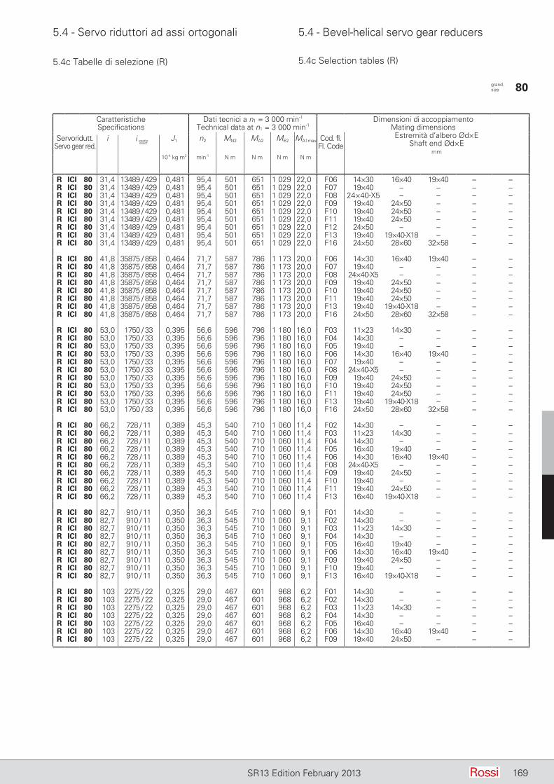
5.4 - Servo riduttori ad assi ortogonali 5.4 - Bevel-helical servo gear reducers
169SR13 Edition February 2013
5.4c Tabelle di selezione (R) 5.4c Selection tables (R)
CaratteristicheSpecifications
Dati tecnici a n1 = 3 000 min-1
Technical data at n1 = 3 000 min-1Dimensioni di accoppiamento
Mating dimensionsEstremità d’albero Ød×E
Shaft end Ød×Emm
Servoridutt.Servo gear red.
i J1 n2 MN2 MA2 ME2 MA1max Cod. fl.Fl. Code
10-4 kg m2 min-1 N m N m N m N m
R ICI 80 31,4 13489 / 429 0,481 95,4 501 651 1 029 22,0 F06 14×30 16×40 19×40 – –R ICI 80 31,4 13489 / 429 0,481 95,4 501 651 1 029 22,0 F07 19×40 – – – –R ICI 80 31,4 13489 / 429 0,481 95,4 501 651 1 029 22,0 F08 24×40-X5 – – – –R ICI 80 31,4 13489 / 429 0,481 95,4 501 651 1 029 22,0 F09 19×40 24×50 – – –R ICI 80 31,4 13489 / 429 0,481 95,4 501 651 1 029 22,0 F10 19×40 24×50 – – –R ICI 80 31,4 13489 / 429 0,481 95,4 501 651 1 029 22,0 F11 19×40 24×50 – – –R ICI 80 31,4 13489 / 429 0,481 95,4 501 651 1 029 22,0 F12 24×50 – – – –R ICI 80 31,4 13489 / 429 0,481 95,4 501 651 1 029 22,0 F13 19×40 19×40-X18 – – –R ICI 80 31,4 13489 / 429 0,481 95,4 501 651 1 029 22,0 F16 24×50 28×60 32×58 – –
R ICI 80 41,8 35875 / 858 0,464 71,7 587 786 1 173 20,0 F06 14×30 16×40 19×40 – –R ICI 80 41,8 35875 / 858 0,464 71,7 587 786 1 173 20,0 F07 19×40 – – – –R ICI 80 41,8 35875 / 858 0,464 71,7 587 786 1 173 20,0 F08 24×40-X5 – – – –R ICI 80 41,8 35875 / 858 0,464 71,7 587 786 1 173 20,0 F09 19×40 24×50 – – –R ICI 80 41,8 35875 / 858 0,464 71,7 587 786 1 173 20,0 F10 19×40 24×50 – – –R ICI 80 41,8 35875 / 858 0,464 71,7 587 786 1 173 20,0 F11 19×40 24×50 – – –R ICI 80 41,8 35875 / 858 0,464 71,7 587 786 1 173 20,0 F13 19×40 19×40-X18 – – –R ICI 80 41,8 35875 / 858 0,464 71,7 587 786 1 173 20,0 F16 24×50 28×60 32×58 – –
R ICI 80 53,0 1750 / 33 0,395 56,6 596 796 1 180 16,0 F03 11×23 14×30 – – –R ICI 80 53,0 1750 / 33 0,395 56,6 596 796 1 180 16,0 F04 14×30 – – – –R ICI 80 53,0 1750 / 33 0,395 56,6 596 796 1 180 16,0 F05 19×40 – – – –R ICI 80 53,0 1750 / 33 0,395 56,6 596 796 1 180 16,0 F06 14×30 16×40 19×40 – –R ICI 80 53,0 1750 / 33 0,395 56,6 596 796 1 180 16,0 F07 19×40 – – – –R ICI 80 53,0 1750 / 33 0,395 56,6 596 796 1 180 16,0 F08 24×40-X5 – – – –R ICI 80 53,0 1750 / 33 0,395 56,6 596 796 1 180 16,0 F09 19×40 24×50 – – –R ICI 80 53,0 1750 / 33 0,395 56,6 596 796 1 180 16,0 F10 19×40 24×50 – – –R ICI 80 53,0 1750 / 33 0,395 56,6 596 796 1 180 16,0 F11 19×40 24×50 – – –R ICI 80 53,0 1750 / 33 0,395 56,6 596 796 1 180 16,0 F13 19×40 19×40-X18 – – –R ICI 80 53,0 1750 / 33 0,395 56,6 596 796 1 180 16,0 F16 24×50 28×60 32×58 – –
R ICI 80 66,2 728 / 11 0,389 45,3 540 710 1 060 11,4 F02 14×30 – – – –R ICI 80 66,2 728 / 11 0,389 45,3 540 710 1 060 11,4 F03 11×23 14×30 – – –R ICI 80 66,2 728 / 11 0,389 45,3 540 710 1 060 11,4 F04 14×30 – – – –R ICI 80 66,2 728 / 11 0,389 45,3 540 710 1 060 11,4 F05 16×40 19×40 – – –R ICI 80 66,2 728 / 11 0,389 45,3 540 710 1 060 11,4 F06 14×30 16×40 19×40 – –R ICI 80 66,2 728 / 11 0,389 45,3 540 710 1 060 11,4 F08 24×40-X5 – – – –R ICI 80 66,2 728 / 11 0,389 45,3 540 710 1 060 11,4 F09 19×40 24×50 – – –R ICI 80 66,2 728 / 11 0,389 45,3 540 710 1 060 11,4 F10 19×40 – – – –R ICI 80 66,2 728 / 11 0,389 45,3 540 710 1 060 11,4 F11 19×40 24×50 – – –R ICI 80 66,2 728 / 11 0,389 45,3 540 710 1 060 11,4 F13 16×40 19×40-X18 – – –
R ICI 80 82,7 910 / 11 0,350 36,3 545 710 1 060 9,1 F01 14×30 – – – –R ICI 80 82,7 910 / 11 0,350 36,3 545 710 1 060 9,1 F02 14×30 – – – –R ICI 80 82,7 910 / 11 0,350 36,3 545 710 1 060 9,1 F03 11×23 14×30 – – –R ICI 80 82,7 910 / 11 0,350 36,3 545 710 1 060 9,1 F04 14×30 – – – –R ICI 80 82,7 910 / 11 0,350 36,3 545 710 1 060 9,1 F05 16×40 19×40 – – –R ICI 80 82,7 910 / 11 0,350 36,3 545 710 1 060 9,1 F06 14×30 16×40 19×40 – –R ICI 80 82,7 910 / 11 0,350 36,3 545 710 1 060 9,1 F09 19×40 24×50 – – –R ICI 80 82,7 910 / 11 0,350 36,3 545 710 1 060 9,1 F10 19×40 – – – –R ICI 80 82,7 910 / 11 0,350 36,3 545 710 1 060 9,1 F13 16×40 19×40-X18 – – –
R ICI 80 103 2275 / 22 0,325 29,0 467 601 968 6,2 F01 14×30 – – – –R ICI 80 103 2275 / 22 0,325 29,0 467 601 968 6,2 F02 14×30 – – – –R ICI 80 103 2275 / 22 0,325 29,0 467 601 968 6,2 F03 11×23 14×30 – – –R ICI 80 103 2275 / 22 0,325 29,0 467 601 968 6,2 F04 14×30 – – – –R ICI 80 103 2275 / 22 0,325 29,0 467 601 968 6,2 F05 16×40 – – – –R ICI 80 103 2275 / 22 0,325 29,0 467 601 968 6,2 F06 14×30 16×40 19×40 – –R ICI 80 103 2275 / 22 0,325 29,0 467 601 968 6,2 F09 19×40 24×50 – – –
grand. size 80
i esattoexact
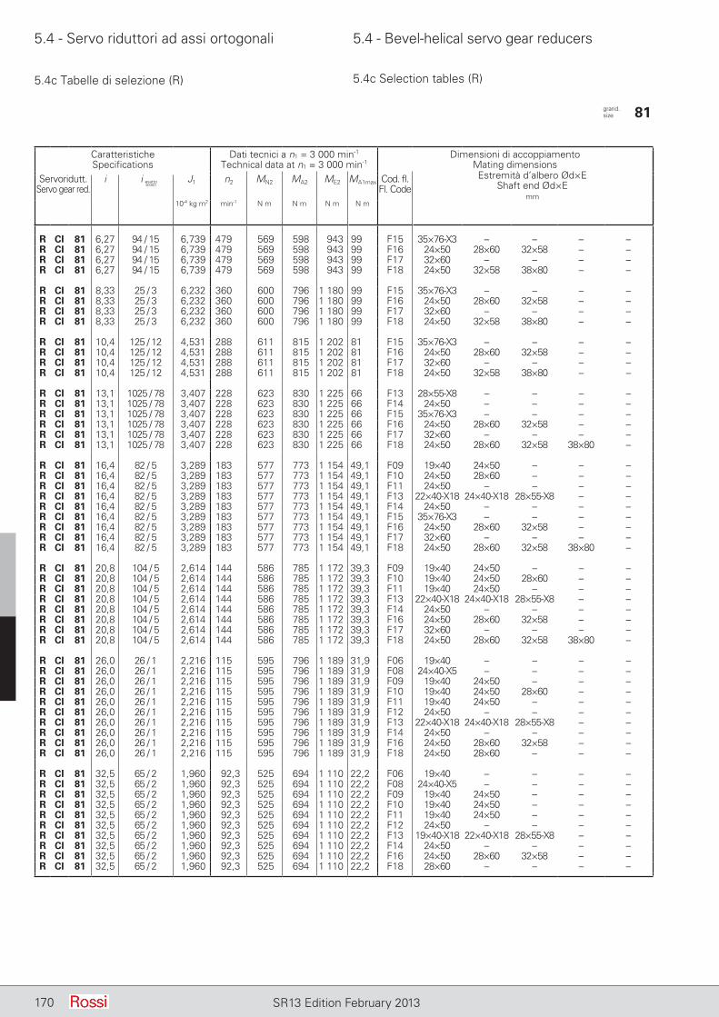
5.4 - Servo riduttori ad assi ortogonali 5.4 - Bevel-helical servo gear reducers
170 SR13 Edition February 2013
5.4c Tabelle di selezione (R) 5.4c Selection tables (R)
CaratteristicheSpecifications
Dati tecnici a n1 = 3 000 min-1
Technical data at n1 = 3 000 min-1Dimensioni di accoppiamento
Mating dimensionsEstremità d’albero Ød×E
Shaft end Ød×Emm
Servoridutt.Servo gear red.
i J1 n2 MN2 MA2 ME2 MA1max Cod. fl.Fl. Code
10-4 kg m2 min-1 N m N m N m N m
R CI 81 6,27 94 / 15 6,739 479 569 598 943 99 F15 35×76-X3 – – – –R CI 81 6,27 94 / 15 6,739 479 569 598 943 99 F16 24×50 28×60 32×58 – –R CI 81 6,27 94 / 15 6,739 479 569 598 943 99 F17 32×60 – – – –R CI 81 6,27 94 / 15 6,739 479 569 598 943 99 F18 24×50 32×58 38×80 – –
R CI 81 8,33 25 / 3 6,232 360 600 796 1 180 99 F15 35×76-X3 – – – –R CI 81 8,33 25 / 3 6,232 360 600 796 1 180 99 F16 24×50 28×60 32×58 – –R CI 81 8,33 25 / 3 6,232 360 600 796 1 180 99 F17 32×60 – – – –R CI 81 8,33 25 / 3 6,232 360 600 796 1 180 99 F18 24×50 32×58 38×80 – –
R CI 81 10,4 125 / 12 4,531 288 611 815 1 202 81 F15 35×76-X3 – – – –R CI 81 10,4 125 / 12 4,531 288 611 815 1 202 81 F16 24×50 28×60 32×58 – –R CI 81 10,4 125 / 12 4,531 288 611 815 1 202 81 F17 32×60 – – – –R CI 81 10,4 125 / 12 4,531 288 611 815 1 202 81 F18 24×50 32×58 38×80 – –
R CI 81 13,1 1025 / 78 3,407 228 623 830 1 225 66 F13 28×55-X8 – – – –R CI 81 13,1 1025 / 78 3,407 228 623 830 1 225 66 F14 24×50 – – – –R CI 81 13,1 1025 / 78 3,407 228 623 830 1 225 66 F15 35×76-X3 – – – –R CI 81 13,1 1025 / 78 3,407 228 623 830 1 225 66 F16 24×50 28×60 32×58 – –R CI 81 13,1 1025 / 78 3,407 228 623 830 1 225 66 F17 32×60 – – – –R CI 81 13,1 1025 / 78 3,407 228 623 830 1 225 66 F18 24×50 28×60 32×58 38×80 –
R CI 81 16,4 82 / 5 3,289 183 577 773 1 154 49,1 F09 19×40 24×50 – – –R CI 81 16,4 82 / 5 3,289 183 577 773 1 154 49,1 F10 24×50 28×60 – – –R CI 81 16,4 82 / 5 3,289 183 577 773 1 154 49,1 F11 24×50 – – – –R CI 81 16,4 82 / 5 3,289 183 577 773 1 154 49,1 F13 22×40-X18 24×40-X18 28×55-X8 – –R CI 81 16,4 82 / 5 3,289 183 577 773 1 154 49,1 F14 24×50 – – – –R CI 81 16,4 82 / 5 3,289 183 577 773 1 154 49,1 F15 35×76-X3 – – – –R CI 81 16,4 82 / 5 3,289 183 577 773 1 154 49,1 F16 24×50 28×60 32×58 – –R CI 81 16,4 82 / 5 3,289 183 577 773 1 154 49,1 F17 32×60 – – – –R CI 81 16,4 82 / 5 3,289 183 577 773 1 154 49,1 F18 24×50 28×60 32×58 38×80 –
R CI 81 20,8 104 / 5 2,614 144 586 785 1 172 39,3 F09 19×40 24×50 – – –R CI 81 20,8 104 / 5 2,614 144 586 785 1 172 39,3 F10 19×40 24×50 28×60 – –R CI 81 20,8 104 / 5 2,614 144 586 785 1 172 39,3 F11 19×40 24×50 – – –R CI 81 20,8 104 / 5 2,614 144 586 785 1 172 39,3 F13 22×40-X18 24×40-X18 28×55-X8 – –R CI 81 20,8 104 / 5 2,614 144 586 785 1 172 39,3 F14 24×50 – – – –R CI 81 20,8 104 / 5 2,614 144 586 785 1 172 39,3 F16 24×50 28×60 32×58 – –R CI 81 20,8 104 / 5 2,614 144 586 785 1 172 39,3 F17 32×60 – – – –R CI 81 20,8 104 / 5 2,614 144 586 785 1 172 39,3 F18 24×50 28×60 32×58 38×80 –
R CI 81 26,0 26 / 1 2,216 115 595 796 1 189 31,9 F06 19×40 – – – –R CI 81 26,0 26 / 1 2,216 115 595 796 1 189 31,9 F08 24×40-X5 – – – –R CI 81 26,0 26 / 1 2,216 115 595 796 1 189 31,9 F09 19×40 24×50 – – –R CI 81 26,0 26 / 1 2,216 115 595 796 1 189 31,9 F10 19×40 24×50 28×60 – –R CI 81 26,0 26 / 1 2,216 115 595 796 1 189 31,9 F11 19×40 24×50 – – –R CI 81 26,0 26 / 1 2,216 115 595 796 1 189 31,9 F12 24×50 – – – –R CI 81 26,0 26 / 1 2,216 115 595 796 1 189 31,9 F13 22×40-X18 24×40-X18 28×55-X8 – –R CI 81 26,0 26 / 1 2,216 115 595 796 1 189 31,9 F14 24×50 – – – –R CI 81 26,0 26 / 1 2,216 115 595 796 1 189 31,9 F16 24×50 28×60 32×58 – –R CI 81 26,0 26 / 1 2,216 115 595 796 1 189 31,9 F18 24×50 28×60 – – –
R CI 81 32,5 65 / 2 1,960 92,3 525 694 1 110 22,2 F06 19×40 – – – –R CI 81 32,5 65 / 2 1,960 92,3 525 694 1 110 22,2 F08 24×40-X5 – – – –R CI 81 32,5 65 / 2 1,960 92,3 525 694 1 110 22,2 F09 19×40 24×50 – – –R CI 81 32,5 65 / 2 1,960 92,3 525 694 1 110 22,2 F10 19×40 24×50 – – –R CI 81 32,5 65 / 2 1,960 92,3 525 694 1 110 22,2 F11 19×40 24×50 – – –R CI 81 32,5 65 / 2 1,960 92,3 525 694 1 110 22,2 F12 24×50 – – – –R CI 81 32,5 65 / 2 1,960 92,3 525 694 1 110 22,2 F13 19×40-X18 22×40-X18 28×55-X8 – –R CI 81 32,5 65 / 2 1,960 92,3 525 694 1 110 22,2 F14 24×50 – – – –R CI 81 32,5 65 / 2 1,960 92,3 525 694 1 110 22,2 F16 24×50 28×60 32×58 – –R CI 81 32,5 65 / 2 1,960 92,3 525 694 1 110 22,2 F18 28×60 – – – –
grand. size 81
i esattoexact
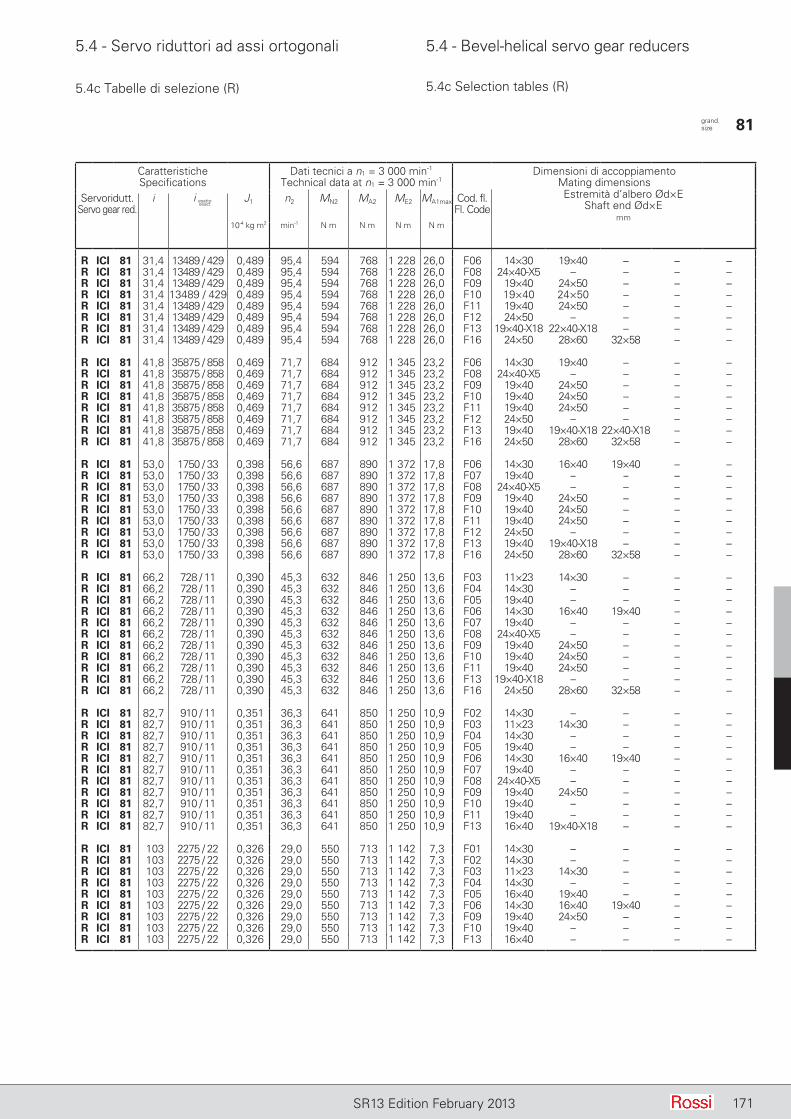
5.4 - Servo riduttori ad assi ortogonali 5.4 - Bevel-helical servo gear reducers
171SR13 Edition February 2013
5.4c Tabelle di selezione (R) 5.4c Selection tables (R)
CaratteristicheSpecifications
Dati tecnici a n1 = 3 000 min-1
Technical data at n1 = 3 000 min-1Dimensioni di accoppiamento
Mating dimensionsEstremità d’albero Ød×E
Shaft end Ød×Emm
Servoridutt.Servo gear red.
i J1 n2 MN2 MA2 ME2 MA1max Cod. fl.Fl. Code
10-4 kg m2 min-1 N m N m N m N m
R ICI 81 31,4 13489 / 429 0,489 95,4 594 768 1 228 26,0 F06 14×30 19×40 – – –R ICI 81 31,4 13489 / 429 0,489 95,4 594 768 1 228 26,0 F08 24×40-X5 – – – –R ICI 81 31,4 13489 / 429 0,489 95,4 594 768 1 228 26,0 F09 19×40 24×50 – – –R ICI 81 31,4 13489 / 429 0,489 95,4 594 768 1 228 26,0 F10 19×40 24×50 – – –R ICI 81 31,4 13489 / 429 0,489 95,4 594 768 1 228 26,0 F11 19×40 24×50 – – –R ICI 81 31,4 13489 / 429 0,489 95,4 594 768 1 228 26,0 F12 24×50 – – – –R ICI 81 31,4 13489 / 429 0,489 95,4 594 768 1 228 26,0 F13 19×40-X18 22×40-X18 – – –R ICI 81 31,4 13489 / 429 0,489 95,4 594 768 1 228 26,0 F16 24×50 28×60 32×58 – –
R ICI 81 41,8 35875 / 858 0,469 71,7 684 912 1 345 23,2 F06 14×30 19×40 – – –R ICI 81 41,8 35875 / 858 0,469 71,7 684 912 1 345 23,2 F08 24×40-X5 – – – –R ICI 81 41,8 35875 / 858 0,469 71,7 684 912 1 345 23,2 F09 19×40 24×50 – – –R ICI 81 41,8 35875 / 858 0,469 71,7 684 912 1 345 23,2 F10 19×40 24×50 – – –R ICI 81 41,8 35875 / 858 0,469 71,7 684 912 1 345 23,2 F11 19×40 24×50 – – –R ICI 81 41,8 35875 / 858 0,469 71,7 684 912 1 345 23,2 F12 24×50 – – – –R ICI 81 41,8 35875 / 858 0,469 71,7 684 912 1 345 23,2 F13 19×40 19×40-X18 22×40-X18 – –R ICI 81 41,8 35875 / 858 0,469 71,7 684 912 1 345 23,2 F16 24×50 28×60 32×58 – –
R ICI 81 53,0 1750 / 33 0,398 56,6 687 890 1 372 17,8 F06 14×30 16×40 19×40 – –R ICI 81 53,0 1750 / 33 0,398 56,6 687 890 1 372 17,8 F07 19×40 – – – –R ICI 81 53,0 1750 / 33 0,398 56,6 687 890 1 372 17,8 F08 24×40-X5 – – – –R ICI 81 53,0 1750 / 33 0,398 56,6 687 890 1 372 17,8 F09 19×40 24×50 – – –R ICI 81 53,0 1750 / 33 0,398 56,6 687 890 1 372 17,8 F10 19×40 24×50 – – –R ICI 81 53,0 1750 / 33 0,398 56,6 687 890 1 372 17,8 F11 19×40 24×50 – – –R ICI 81 53,0 1750 / 33 0,398 56,6 687 890 1 372 17,8 F12 24×50 – – – –R ICI 81 53,0 1750 / 33 0,398 56,6 687 890 1 372 17,8 F13 19×40 19×40-X18 – – –R ICI 81 53,0 1750 / 33 0,398 56,6 687 890 1 372 17,8 F16 24×50 28×60 32×58 – –
R ICI 81 66,2 728 / 11 0,390 45,3 632 846 1 250 13,6 F03 11×23 14×30 – – –R ICI 81 66,2 728 / 11 0,390 45,3 632 846 1 250 13,6 F04 14×30 – – – –R ICI 81 66,2 728 / 11 0,390 45,3 632 846 1 250 13,6 F05 19×40 – – – –R ICI 81 66,2 728 / 11 0,390 45,3 632 846 1 250 13,6 F06 14×30 16×40 19×40 – –R ICI 81 66,2 728 / 11 0,390 45,3 632 846 1 250 13,6 F07 19×40 – – – –R ICI 81 66,2 728 / 11 0,390 45,3 632 846 1 250 13,6 F08 24×40-X5 – – – –R ICI 81 66,2 728 / 11 0,390 45,3 632 846 1 250 13,6 F09 19×40 24×50 – – –R ICI 81 66,2 728 / 11 0,390 45,3 632 846 1 250 13,6 F10 19×40 24×50 – – –R ICI 81 66,2 728 / 11 0,390 45,3 632 846 1 250 13,6 F11 19×40 24×50 – – –R ICI 81 66,2 728 / 11 0,390 45,3 632 846 1 250 13,6 F13 19×40-X18 – – – –R ICI 81 66,2 728 / 11 0,390 45,3 632 846 1 250 13,6 F16 24×50 28×60 32×58 – –
R ICI 81 82,7 910 / 11 0,351 36,3 641 850 1 250 10,9 F02 14×30 – – – –R ICI 81 82,7 910 / 11 0,351 36,3 641 850 1 250 10,9 F03 11×23 14×30 – – –R ICI 81 82,7 910 / 11 0,351 36,3 641 850 1 250 10,9 F04 14×30 – – – –R ICI 81 82,7 910 / 11 0,351 36,3 641 850 1 250 10,9 F05 19×40 – – – –R ICI 81 82,7 910 / 11 0,351 36,3 641 850 1 250 10,9 F06 14×30 16×40 19×40 – –R ICI 81 82,7 910 / 11 0,351 36,3 641 850 1 250 10,9 F07 19×40 – – – –R ICI 81 82,7 910 / 11 0,351 36,3 641 850 1 250 10,9 F08 24×40-X5 – – – –R ICI 81 82,7 910 / 11 0,351 36,3 641 850 1 250 10,9 F09 19×40 24×50 – – –R ICI 81 82,7 910 / 11 0,351 36,3 641 850 1 250 10,9 F10 19×40 – – – –R ICI 81 82,7 910 / 11 0,351 36,3 641 850 1 250 10,9 F11 19×40 – – – –R ICI 81 82,7 910 / 11 0,351 36,3 641 850 1 250 10,9 F13 16×40 19×40-X18 – – –
R ICI 81 103 2275 / 22 0,326 29,0 550 713 1 142 7,3 F01 14×30 – – – –R ICI 81 103 2275 / 22 0,326 29,0 550 713 1 142 7,3 F02 14×30 – – – –R ICI 81 103 2275 / 22 0,326 29,0 550 713 1 142 7,3 F03 11×23 14×30 – – –R ICI 81 103 2275 / 22 0,326 29,0 550 713 1 142 7,3 F04 14×30 – – – –R ICI 81 103 2275 / 22 0,326 29,0 550 713 1 142 7,3 F05 16×40 19×40 – – –R ICI 81 103 2275 / 22 0,326 29,0 550 713 1 142 7,3 F06 14×30 16×40 19×40 – –R ICI 81 103 2275 / 22 0,326 29,0 550 713 1 142 7,3 F09 19×40 24×50 – – –R ICI 81 103 2275 / 22 0,326 29,0 550 713 1 142 7,3 F10 19×40 – – – –R ICI 81 103 2275 / 22 0,326 29,0 550 713 1 142 7,3 F13 16×40 – – – –
grand. size 81
i esattoexact
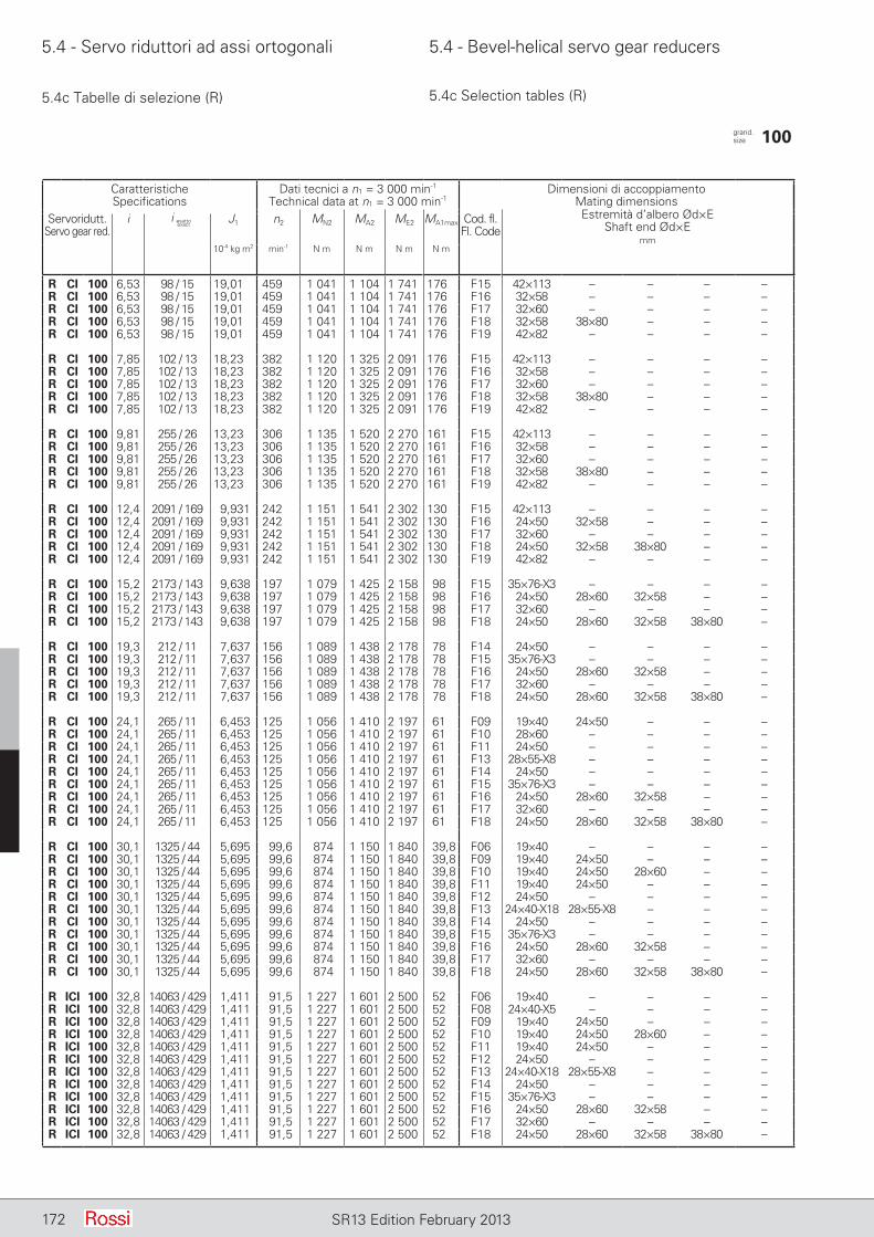
5.4 - Servo riduttori ad assi ortogonali 5.4 - Bevel-helical servo gear reducers
172 SR13 Edition February 2013
5.4c Tabelle di selezione (R) 5.4c Selection tables (R)
CaratteristicheSpecifications
Dati tecnici a n1 = 3 000 min-1
Technical data at n1 = 3 000 min-1Dimensioni di accoppiamento
Mating dimensionsEstremità d’albero Ød×E
Shaft end Ød×Emm
Servoridutt.Servo gear red.
i J1 n2 MN2 MA2 ME2 MA1max Cod. fl.Fl. Code
10-4 kg m2 min-1 N m N m N m N m
R CI 100 6,53 98 / 15 19,01 459 1 041 1 104 1 741 176 F15 42×113 – – – –R CI 100 6,53 98 / 15 19,01 459 1 041 1 104 1 741 176 F16 32×58 – – – –R CI 100 6,53 98 / 15 19,01 459 1 041 1 104 1 741 176 F17 32×60 – – – –R CI 100 6,53 98 / 15 19,01 459 1 041 1 104 1 741 176 F18 32×58 38×80 – – –R CI 100 6,53 98 / 15 19,01 459 1 041 1 104 1 741 176 F19 42×82 – – – –
R CI 100 7,85 102 / 13 18,23 382 1 120 1 325 2 091 176 F15 42×113 – – – –R CI 100 7,85 102 / 13 18,23 382 1 120 1 325 2 091 176 F16 32×58 – – – –R CI 100 7,85 102 / 13 18,23 382 1 120 1 325 2 091 176 F17 32×60 – – – –R CI 100 7,85 102 / 13 18,23 382 1 120 1 325 2 091 176 F18 32×58 38×80 – – –R CI 100 7,85 102 / 13 18,23 382 1 120 1 325 2 091 176 F19 42×82 – – – –
R CI 100 9,81 255 / 26 13,23 306 1 135 1 520 2 270 161 F15 42×113 – – – –R CI 100 9,81 255 / 26 13,23 306 1 135 1 520 2 270 161 F16 32×58 – – – –R CI 100 9,81 255 / 26 13,23 306 1 135 1 520 2 270 161 F17 32×60 – – – –R CI 100 9,81 255 / 26 13,23 306 1 135 1 520 2 270 161 F18 32×58 38×80 – – –R CI 100 9,81 255 / 26 13,23 306 1 135 1 520 2 270 161 F19 42×82 – – – –
R CI 100 12,4 2091 / 169 9,931 242 1 151 1 541 2 302 130 F15 42×113 – – – –R CI 100 12,4 2091 / 169 9,931 242 1 151 1 541 2 302 130 F16 24×50 32×58 – – –R CI 100 12,4 2091 / 169 9,931 242 1 151 1 541 2 302 130 F17 32×60 – – – –R CI 100 12,4 2091 / 169 9,931 242 1 151 1 541 2 302 130 F18 24×50 32×58 38×80 – –R CI 100 12,4 2091 / 169 9,931 242 1 151 1 541 2 302 130 F19 42×82 – – – –
R CI 100 15,2 2173 / 143 9,638 197 1 079 1 425 2 158 98 F15 35×76-X3 – – – –R CI 100 15,2 2173 / 143 9,638 197 1 079 1 425 2 158 98 F16 24×50 28×60 32×58 – –R CI 100 15,2 2173 / 143 9,638 197 1 079 1 425 2 158 98 F17 32×60 – – – –R CI 100 15,2 2173 / 143 9,638 197 1 079 1 425 2 158 98 F18 24×50 28×60 32×58 38×80 –
R CI 100 19,3 212 / 11 7,637 156 1 089 1 438 2 178 78 F14 24×50 – – – –R CI 100 19,3 212 / 11 7,637 156 1 089 1 438 2 178 78 F15 35×76-X3 – – – –R CI 100 19,3 212 / 11 7,637 156 1 089 1 438 2 178 78 F16 24×50 28×60 32×58 – –R CI 100 19,3 212 / 11 7,637 156 1 089 1 438 2 178 78 F17 32×60 – – – –R CI 100 19,3 212 / 11 7,637 156 1 089 1 438 2 178 78 F18 24×50 28×60 32×58 38×80 –
R CI 100 24,1 265 / 11 6,453 125 1 056 1 410 2 197 61 F09 19×40 24×50 – – –R CI 100 24,1 265 / 11 6,453 125 1 056 1 410 2 197 61 F10 28×60 – – – –R CI 100 24,1 265 / 11 6,453 125 1 056 1 410 2 197 61 F11 24×50 – – – –R CI 100 24,1 265 / 11 6,453 125 1 056 1 410 2 197 61 F13 28×55-X8 – – – –R CI 100 24,1 265 / 11 6,453 125 1 056 1 410 2 197 61 F14 24×50 – – – –R CI 100 24,1 265 / 11 6,453 125 1 056 1 410 2 197 61 F15 35×76-X3 – – – –R CI 100 24,1 265 / 11 6,453 125 1 056 1 410 2 197 61 F16 24×50 28×60 32×58 – –R CI 100 24,1 265 / 11 6,453 125 1 056 1 410 2 197 61 F17 32×60 – – – –R CI 100 24,1 265 / 11 6,453 125 1 056 1 410 2 197 61 F18 24×50 28×60 32×58 38×80 –
R CI 100 30,1 1325 / 44 5,695 99,6 874 1 150 1 840 39,8 F06 19×40 – – – –R CI 100 30,1 1325 / 44 5,695 99,6 874 1 150 1 840 39,8 F09 19×40 24×50 – – –R CI 100 30,1 1325 / 44 5,695 99,6 874 1 150 1 840 39,8 F10 19×40 24×50 28×60 – –R CI 100 30,1 1325 / 44 5,695 99,6 874 1 150 1 840 39,8 F11 19×40 24×50 – – –R CI 100 30,1 1325 / 44 5,695 99,6 874 1 150 1 840 39,8 F12 24×50 – – – –R CI 100 30,1 1325 / 44 5,695 99,6 874 1 150 1 840 39,8 F13 24×40-X18 28×55-X8 – – –R CI 100 30,1 1325 / 44 5,695 99,6 874 1 150 1 840 39,8 F14 24×50 – – – –R CI 100 30,1 1325 / 44 5,695 99,6 874 1 150 1 840 39,8 F15 35×76-X3 – – – –R CI 100 30,1 1325 / 44 5,695 99,6 874 1 150 1 840 39,8 F16 24×50 28×60 32×58 – –R CI 100 30,1 1325 / 44 5,695 99,6 874 1 150 1 840 39,8 F17 32×60 – – – –R CI 100 30,1 1325 / 44 5,695 99,6 874 1 150 1 840 39,8 F18 24×50 28×60 32×58 38×80 –
R ICI 100 32,8 14063 / 429 1,411 91,5 1 227 1 601 2 500 52 F06 19×40 – – – –R ICI 100 32,8 14063 / 429 1,411 91,5 1 227 1 601 2 500 52 F08 24×40-X5 – – – –R ICI 100 32,8 14063 / 429 1,411 91,5 1 227 1 601 2 500 52 F09 19×40 24×50 – – –R ICI 100 32,8 14063 / 429 1,411 91,5 1 227 1 601 2 500 52 F10 19×40 24×50 28×60 – –R ICI 100 32,8 14063 / 429 1,411 91,5 1 227 1 601 2 500 52 F11 19×40 24×50 – – –R ICI 100 32,8 14063 / 429 1,411 91,5 1 227 1 601 2 500 52 F12 24×50 – – – –R ICI 100 32,8 14063 / 429 1,411 91,5 1 227 1 601 2 500 52 F13 24×40-X18 28×55-X8 – – –R ICI 100 32,8 14063 / 429 1,411 91,5 1 227 1 601 2 500 52 F14 24×50 – – – –R ICI 100 32,8 14063 / 429 1,411 91,5 1 227 1 601 2 500 52 F15 35×76-X3 – – – –R ICI 100 32,8 14063 / 429 1,411 91,5 1 227 1 601 2 500 52 F16 24×50 28×60 32×58 – –R ICI 100 32,8 14063 / 429 1,411 91,5 1 227 1 601 2 500 52 F17 32×60 – – – –R ICI 100 32,8 14063 / 429 1,411 91,5 1 227 1 601 2 500 52 F18 24×50 28×60 32×58 38×80 –
grand. size 100
i esattoexact
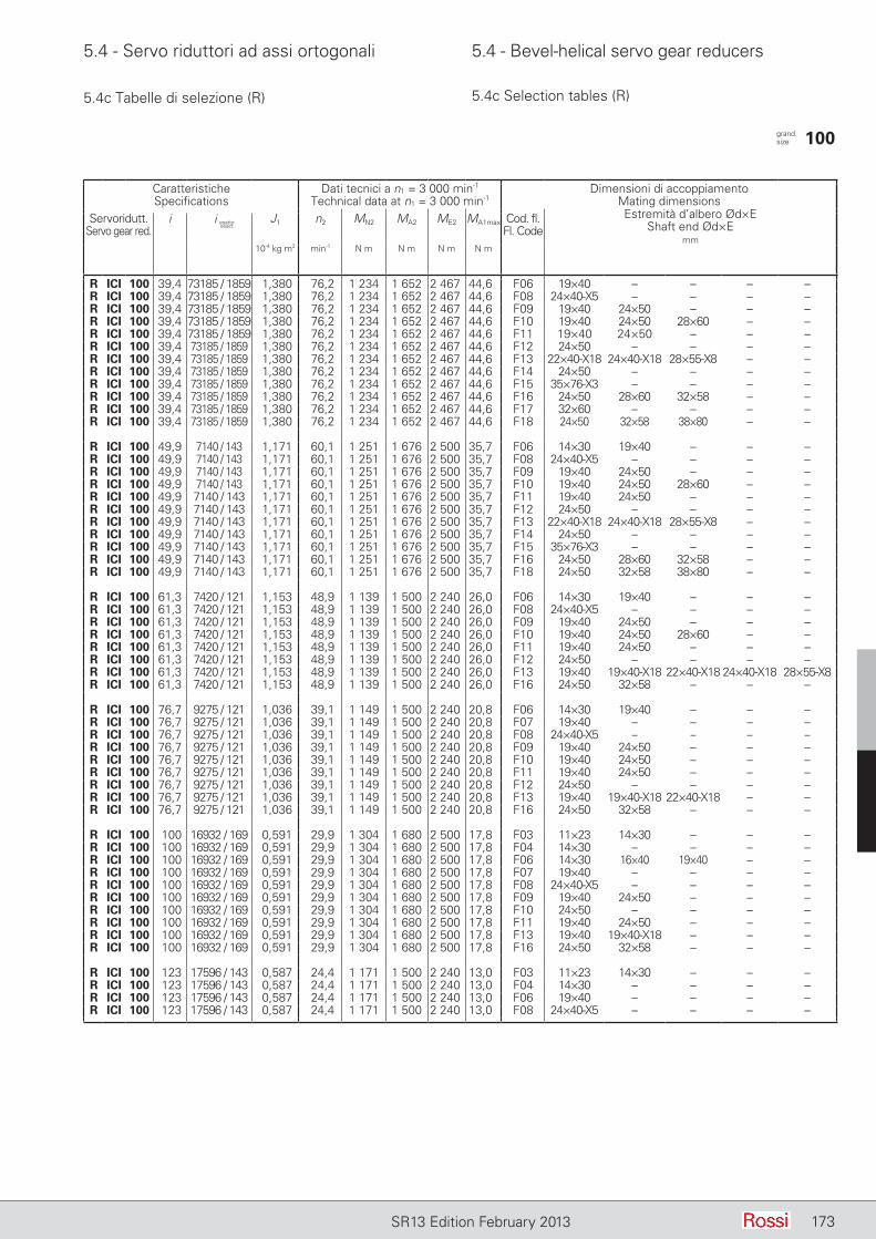
5.4 - Servo riduttori ad assi ortogonali 5.4 - Bevel-helical servo gear reducers
173SR13 Edition February 2013
5.4c Tabelle di selezione (R) 5.4c Selection tables (R)
CaratteristicheSpecifications
Dati tecnici a n1 = 3 000 min-1
Technical data at n1 = 3 000 min-1Dimensioni di accoppiamento
Mating dimensionsEstremità d’albero Ød×E
Shaft end Ød×Emm
Servoridutt.Servo gear red.
i J1 n2 MN2 MA2 ME2 MA1max Cod. fl.Fl. Code
10-4 kg m2 min-1 N m N m N m N m
R ICI 100 39,4 73185 / 1859 1,380 76,2 1 234 1 652 2 467 44,6 F06 19×40 – – – –R ICI 100 39,4 73185 / 1859 1,380 76,2 1 234 1 652 2 467 44,6 F08 24×40-X5 – – – –R ICI 100 39,4 73185 / 1859 1,380 76,2 1 234 1 652 2 467 44,6 F09 19×40 24×50 – – –R ICI 100 39,4 73185 / 1859 1,380 76,2 1 234 1 652 2 467 44,6 F10 19×40 24×50 28×60 – –R ICI 100 39,4 73185 / 1859 1,380 76,2 1 234 1 652 2 467 44,6 F11 19×40 24×50 – – –R ICI 100 39,4 73185 / 1859 1,380 76,2 1 234 1 652 2 467 44,6 F12 24×50 – – – –R ICI 100 39,4 73185 / 1859 1,380 76,2 1 234 1 652 2 467 44,6 F13 22×40-X18 24×40-X18 28×55-X8 – –R ICI 100 39,4 73185 / 1859 1,380 76,2 1 234 1 652 2 467 44,6 F14 24×50 – – – –R ICI 100 39,4 73185 / 1859 1,380 76,2 1 234 1 652 2 467 44,6 F15 35×76-X3 – – – –R ICI 100 39,4 73185 / 1859 1,380 76,2 1 234 1 652 2 467 44,6 F16 24×50 28×60 32×58 – –R ICI 100 39,4 73185 / 1859 1,380 76,2 1 234 1 652 2 467 44,6 F17 32×60 – – – –R ICI 100 39,4 73185 / 1859 1,380 76,2 1 234 1 652 2 467 44,6 F18 24×50 32×58 38×80 – –
R ICI 100 49,9 7140 / 143 1,171 60,1 1 251 1 676 2 500 35,7 F06 14×30 19×40 – – –R ICI 100 49,9 7140 / 143 1,171 60,1 1 251 1 676 2 500 35,7 F08 24×40-X5 – – – –R ICI 100 49,9 7140 / 143 1,171 60,1 1 251 1 676 2 500 35,7 F09 19×40 24×50 – – –R ICI 100 49,9 7140 / 143 1,171 60,1 1 251 1 676 2 500 35,7 F10 19×40 24×50 28×60 – –R ICI 100 49,9 7140 / 143 1,171 60,1 1 251 1 676 2 500 35,7 F11 19×40 24×50 – – –R ICI 100 49,9 7140 / 143 1,171 60,1 1 251 1 676 2 500 35,7 F12 24×50 – – – –R ICI 100 49,9 7140 / 143 1,171 60,1 1 251 1 676 2 500 35,7 F13 22×40-X18 24×40-X18 28×55-X8 – –R ICI 100 49,9 7140 / 143 1,171 60,1 1 251 1 676 2 500 35,7 F14 24×50 – – – –R ICI 100 49,9 7140 / 143 1,171 60,1 1 251 1 676 2 500 35,7 F15 35×76-X3 – – – –R ICI 100 49,9 7140 / 143 1,171 60,1 1 251 1 676 2 500 35,7 F16 24×50 28×60 32×58 – –R ICI 100 49,9 7140 / 143 1,171 60,1 1 251 1 676 2 500 35,7 F18 24×50 32×58 38×80 – –
R ICI 100 61,3 7420 / 121 1,153 48,9 1 139 1 500 2 240 26,0 F06 14×30 19×40 – – –R ICI 100 61,3 7420 / 121 1,153 48,9 1 139 1 500 2 240 26,0 F08 24×40-X5 – – – –R ICI 100 61,3 7420 / 121 1,153 48,9 1 139 1 500 2 240 26,0 F09 19×40 24×50 – – –R ICI 100 61,3 7420 / 121 1,153 48,9 1 139 1 500 2 240 26,0 F10 19×40 24×50 28×60 – –R ICI 100 61,3 7420 / 121 1,153 48,9 1 139 1 500 2 240 26,0 F11 19×40 24×50 – – –R ICI 100 61,3 7420 / 121 1,153 48,9 1 139 1 500 2 240 26,0 F12 24×50 – – – –R ICI 100 61,3 7420 / 121 1,153 48,9 1 139 1 500 2 240 26,0 F13 19×40 19×40-X18 22×40-X18 24×40-X18 28×55-X8R ICI 100 61,3 7420 / 121 1,153 48,9 1 139 1 500 2 240 26,0 F16 24×50 32×58 – – –
R ICI 100 76,7 9275 / 121 1,036 39,1 1 149 1 500 2 240 20,8 F06 14×30 19×40 – – –R ICI 100 76,7 9275 / 121 1,036 39,1 1 149 1 500 2 240 20,8 F07 19×40 – – – –R ICI 100 76,7 9275 / 121 1,036 39,1 1 149 1 500 2 240 20,8 F08 24×40-X5 – – – –R ICI 100 76,7 9275 / 121 1,036 39,1 1 149 1 500 2 240 20,8 F09 19×40 24×50 – – –R ICI 100 76,7 9275 / 121 1,036 39,1 1 149 1 500 2 240 20,8 F10 19×40 24×50 – – –R ICI 100 76,7 9275 / 121 1,036 39,1 1 149 1 500 2 240 20,8 F11 19×40 24×50 – – –R ICI 100 76,7 9275 / 121 1,036 39,1 1 149 1 500 2 240 20,8 F12 24×50 – – – –R ICI 100 76,7 9275 / 121 1,036 39,1 1 149 1 500 2 240 20,8 F13 19×40 19×40-X18 22×40-X18 – –R ICI 100 76,7 9275 / 121 1,036 39,1 1 149 1 500 2 240 20,8 F16 24×50 32×58 – – –
R ICI 100 100 16932 / 169 0,591 29,9 1 304 1 680 2 500 17,8 F03 11×23 14×30 – – –R ICI 100 100 16932 / 169 0,591 29,9 1 304 1 680 2 500 17,8 F04 14×30 – – – –R ICI 100 100 16932 / 169 0,591 29,9 1 304 1 680 2 500 17,8 F06 14×30 16×40 19×40 – –R ICI 100 100 16932 / 169 0,591 29,9 1 304 1 680 2 500 17,8 F07 19×40 – – – –R ICI 100 100 16932 / 169 0,591 29,9 1 304 1 680 2 500 17,8 F08 24×40-X5 – – – –R ICI 100 100 16932 / 169 0,591 29,9 1 304 1 680 2 500 17,8 F09 19×40 24×50 – – –R ICI 100 100 16932 / 169 0,591 29,9 1 304 1 680 2 500 17,8 F10 24×50 – – – –R ICI 100 100 16932 / 169 0,591 29,9 1 304 1 680 2 500 17,8 F11 19×40 24×50 – – –R ICI 100 100 16932 / 169 0,591 29,9 1 304 1 680 2 500 17,8 F13 19×40 19×40-X18 – – –R ICI 100 100 16932 / 169 0,591 29,9 1 304 1 680 2 500 17,8 F16 24×50 32×58 – – –
R ICI 100 123 17596 / 143 0,587 24,4 1 171 1 500 2 240 13,0 F03 11×23 14×30 – – –R ICI 100 123 17596 / 143 0,587 24,4 1 171 1 500 2 240 13,0 F04 14×30 – – – –R ICI 100 123 17596 / 143 0,587 24,4 1 171 1 500 2 240 13,0 F06 19×40 – – – –R ICI 100 123 17596 / 143 0,587 24,4 1 171 1 500 2 240 13,0 F08 24×40-X5 – – – –
grand. size 100
i esattoexact
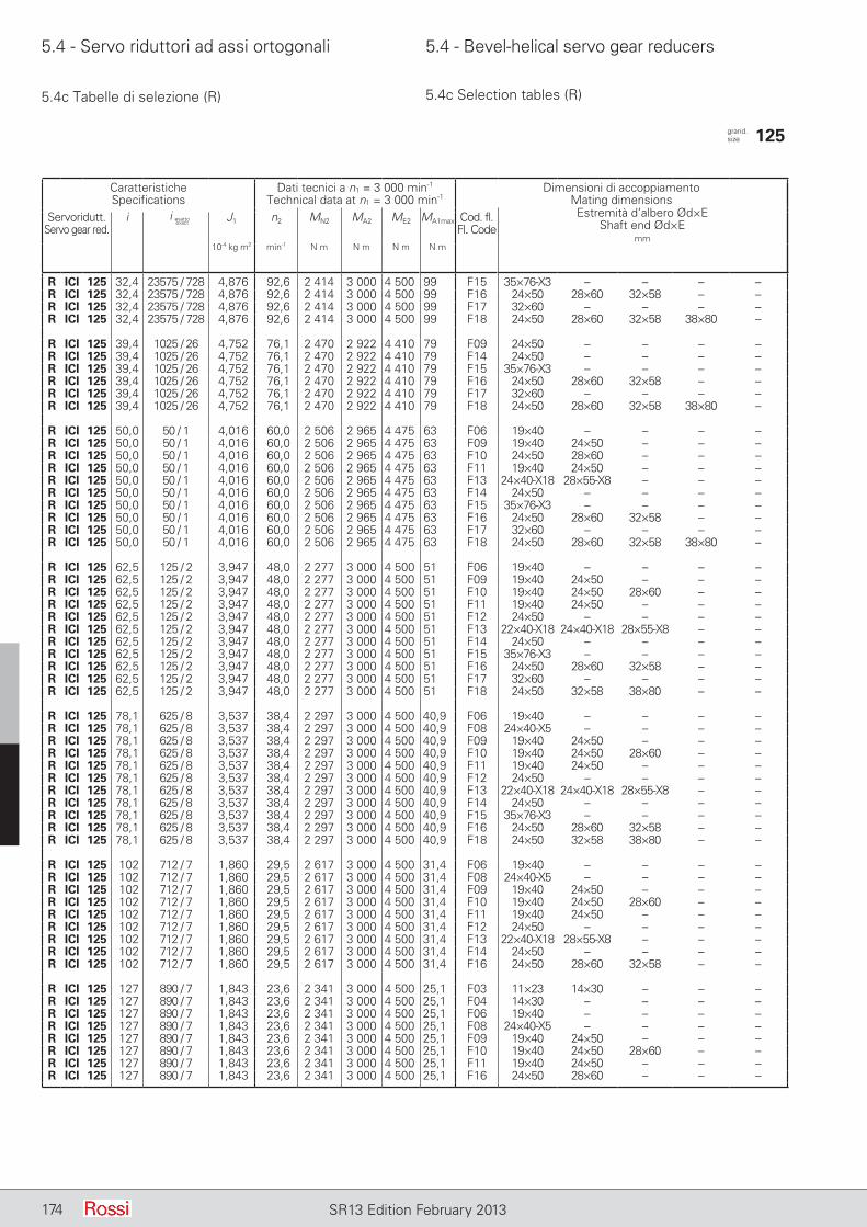
5.4 - Servo riduttori ad assi ortogonali 5.4 - Bevel-helical servo gear reducers
174 SR13 Edition February 2013
5.4c Tabelle di selezione (R) 5.4c Selection tables (R)
CaratteristicheSpecifications
Dati tecnici a n1 = 3 000 min-1
Technical data at n1 = 3 000 min-1Dimensioni di accoppiamento
Mating dimensionsEstremità d’albero Ød×E
Shaft end Ød×Emm
Servoridutt.Servo gear red.
i J1 n2 MN2 MA2 ME2 MA1max Cod. fl.Fl. Code
10-4 kg m2 min-1 N m N m N m N m
R ICI 125 32,4 23575 / 728 4,876 92,6 2 414 3 000 4 500 99 F15 35×76-X3 – – – –R ICI 125 32,4 23575 / 728 4,876 92,6 2 414 3 000 4 500 99 F16 24×50 28×60 32×58 – –R ICI 125 32,4 23575 / 728 4,876 92,6 2 414 3 000 4 500 99 F17 32×60 – – – –R ICI 125 32,4 23575 / 728 4,876 92,6 2 414 3 000 4 500 99 F18 24×50 28×60 32×58 38×80 –
R ICI 125 39,4 1025 / 26 4,752 76,1 2 470 2 922 4 410 79 F09 24×50 – – – –R ICI 125 39,4 1025 / 26 4,752 76,1 2 470 2 922 4 410 79 F14 24×50 – – – –R ICI 125 39,4 1025 / 26 4,752 76,1 2 470 2 922 4 410 79 F15 35×76-X3 – – – –R ICI 125 39,4 1025 / 26 4,752 76,1 2 470 2 922 4 410 79 F16 24×50 28×60 32×58 – –R ICI 125 39,4 1025 / 26 4,752 76,1 2 470 2 922 4 410 79 F17 32×60 – – – –R ICI 125 39,4 1025 / 26 4,752 76,1 2 470 2 922 4 410 79 F18 24×50 28×60 32×58 38×80 –
R ICI 125 50,0 50 / 1 4,016 60,0 2 506 2 965 4 475 63 F06 19×40 – – – –R ICI 125 50,0 50 / 1 4,016 60,0 2 506 2 965 4 475 63 F09 19×40 24×50 – – –R ICI 125 50,0 50 / 1 4,016 60,0 2 506 2 965 4 475 63 F10 24×50 28×60 – – –R ICI 125 50,0 50 / 1 4,016 60,0 2 506 2 965 4 475 63 F11 19×40 24×50 – – –R ICI 125 50,0 50 / 1 4,016 60,0 2 506 2 965 4 475 63 F13 24×40-X18 28×55-X8 – – –R ICI 125 50,0 50 / 1 4,016 60,0 2 506 2 965 4 475 63 F14 24×50 – – – –R ICI 125 50,0 50 / 1 4,016 60,0 2 506 2 965 4 475 63 F15 35×76-X3 – – – –R ICI 125 50,0 50 / 1 4,016 60,0 2 506 2 965 4 475 63 F16 24×50 28×60 32×58 – –R ICI 125 50,0 50 / 1 4,016 60,0 2 506 2 965 4 475 63 F17 32×60 – – – –R ICI 125 50,0 50 / 1 4,016 60,0 2 506 2 965 4 475 63 F18 24×50 28×60 32×58 38×80 –
R ICI 125 62,5 125 / 2 3,947 48,0 2 277 3 000 4 500 51 F06 19×40 – – – –R ICI 125 62,5 125 / 2 3,947 48,0 2 277 3 000 4 500 51 F09 19×40 24×50 – – –R ICI 125 62,5 125 / 2 3,947 48,0 2 277 3 000 4 500 51 F10 19×40 24×50 28×60 – –R ICI 125 62,5 125 / 2 3,947 48,0 2 277 3 000 4 500 51 F11 19×40 24×50 – – –R ICI 125 62,5 125 / 2 3,947 48,0 2 277 3 000 4 500 51 F12 24×50 – – – –R ICI 125 62,5 125 / 2 3,947 48,0 2 277 3 000 4 500 51 F13 22×40-X18 24×40-X18 28×55-X8 – –R ICI 125 62,5 125 / 2 3,947 48,0 2 277 3 000 4 500 51 F14 24×50 – – – –R ICI 125 62,5 125 / 2 3,947 48,0 2 277 3 000 4 500 51 F15 35×76-X3 – – – –R ICI 125 62,5 125 / 2 3,947 48,0 2 277 3 000 4 500 51 F16 24×50 28×60 32×58 – –R ICI 125 62,5 125 / 2 3,947 48,0 2 277 3 000 4 500 51 F17 32×60 – – – –R ICI 125 62,5 125 / 2 3,947 48,0 2 277 3 000 4 500 51 F18 24×50 32×58 38×80 – –
R ICI 125 78,1 625 / 8 3,537 38,4 2 297 3 000 4 500 40,9 F06 19×40 – – – –R ICI 125 78,1 625 / 8 3,537 38,4 2 297 3 000 4 500 40,9 F08 24×40-X5 – – – –R ICI 125 78,1 625 / 8 3,537 38,4 2 297 3 000 4 500 40,9 F09 19×40 24×50 – – –R ICI 125 78,1 625 / 8 3,537 38,4 2 297 3 000 4 500 40,9 F10 19×40 24×50 28×60 – –R ICI 125 78,1 625 / 8 3,537 38,4 2 297 3 000 4 500 40,9 F11 19×40 24×50 – – –R ICI 125 78,1 625 / 8 3,537 38,4 2 297 3 000 4 500 40,9 F12 24×50 – – – –R ICI 125 78,1 625 / 8 3,537 38,4 2 297 3 000 4 500 40,9 F13 22×40-X18 24×40-X18 28×55-X8 – –R ICI 125 78,1 625 / 8 3,537 38,4 2 297 3 000 4 500 40,9 F14 24×50 – – – –R ICI 125 78,1 625 / 8 3,537 38,4 2 297 3 000 4 500 40,9 F15 35×76-X3 – – – –R ICI 125 78,1 625 / 8 3,537 38,4 2 297 3 000 4 500 40,9 F16 24×50 28×60 32×58 – –R ICI 125 78,1 625 / 8 3,537 38,4 2 297 3 000 4 500 40,9 F18 24×50 32×58 38×80 – –
R ICI 125 102 712 / 7 1,860 29,5 2 617 3 000 4 500 31,4 F06 19×40 – – – –R ICI 125 102 712 / 7 1,860 29,5 2 617 3 000 4 500 31,4 F08 24×40-X5 – – – –R ICI 125 102 712 / 7 1,860 29,5 2 617 3 000 4 500 31,4 F09 19×40 24×50 – – –R ICI 125 102 712 / 7 1,860 29,5 2 617 3 000 4 500 31,4 F10 19×40 24×50 28×60 – –R ICI 125 102 712 / 7 1,860 29,5 2 617 3 000 4 500 31,4 F11 19×40 24×50 – – –R ICI 125 102 712 / 7 1,860 29,5 2 617 3 000 4 500 31,4 F12 24×50 – – – –R ICI 125 102 712 / 7 1,860 29,5 2 617 3 000 4 500 31,4 F13 22×40-X18 28×55-X8 – – –R ICI 125 102 712 / 7 1,860 29,5 2 617 3 000 4 500 31,4 F14 24×50 – – – –R ICI 125 102 712 / 7 1,860 29,5 2 617 3 000 4 500 31,4 F16 24×50 28×60 32×58 – –
R ICI 125 127 890 / 7 1,843 23,6 2 341 3 000 4 500 25,1 F03 11×23 14×30 – – –R ICI 125 127 890 / 7 1,843 23,6 2 341 3 000 4 500 25,1 F04 14×30 – – – –R ICI 125 127 890 / 7 1,843 23,6 2 341 3 000 4 500 25,1 F06 19×40 – – – –R ICI 125 127 890 / 7 1,843 23,6 2 341 3 000 4 500 25,1 F08 24×40-X5 – – – –R ICI 125 127 890 / 7 1,843 23,6 2 341 3 000 4 500 25,1 F09 19×40 24×50 – – –R ICI 125 127 890 / 7 1,843 23,6 2 341 3 000 4 500 25,1 F10 19×40 24×50 28×60 – –R ICI 125 127 890 / 7 1,843 23,6 2 341 3 000 4 500 25,1 F11 19×40 24×50 – – –R ICI 125 127 890 / 7 1,843 23,6 2 341 3 000 4 500 25,1 F16 24×50 28×60 – – –
grand. size 125
i esattoexact
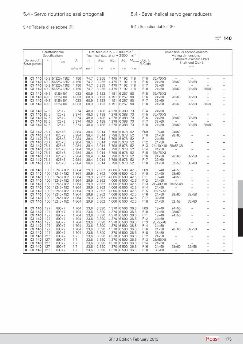
5.4 - Servo riduttori ad assi ortogonali 5.4 - Bevel-helical servo gear reducers
175SR13 Edition February 2013
5.4c Tabelle di selezione (R) 5.4c Selection tables (R)
CaratteristicheSpecifications
Dati tecnici a n1 = 3 000 min-1
Technical data at n1 = 3 000 min-1Dimensioni di accoppiamento
Mating dimensionsEstremità d’albero Ød×E
Shaft end Ød×Emm
Servoridutt.Servo gear red.
i J1 n2 MN2 MA2 ME2 MA1max Cod. fl.Fl. Code
10-4 kg m2 min-1 N m N m N m N m
R ICI 140 40,2 54325 / 1352 4,150 74,7 3 255 4 475 7 192 118 F15 35×76-X3 – – – –R ICI 140 40,2 54325 / 1352 4,150 74,7 3 255 4 475 7 192 118 F16 24×50 28×60 32×58 – –R ICI 140 40,2 54325 / 1352 4,150 74,7 3 255 4 475 7 192 118 F17 32×60 – – – –R ICI 140 40,2 54325 / 1352 4,150 74,7 3 255 4 475 7 192 118 F18 24×50 28×60 32×58 38×80 –R ICI 140 49,3 5125 / 104 4,033 60,9 3 123 4 191 6 257 90 F15 35×76-X3 – – – –R ICI 140 49,3 5125 / 104 4,033 60,9 3 123 4 191 6 257 90 F16 24×50 28×60 32×58 – –R ICI 140 49,3 5125 / 104 4,033 60,9 3 123 4 191 6 257 90 F17 32×60 – – – –R ICI 140 49,3 5125 / 104 4,033 60,9 3 123 4 191 6 257 90 F18 24×50 28×60 32×58 38×80 –
R ICI 140 62,5 125 / 2 3,374 48,0 3 188 4 278 6 388 73 F14 24×50 – – – –R ICI 140 62,5 125 / 2 3,374 48,0 3 188 4 278 6 388 73 F15 35×76-X3 – – – –R ICI 140 62,5 125 / 2 3,374 48,0 3 188 4 278 6 388 73 F16 24×50 28×60 32×58 – –R ICI 140 62,5 125 / 2 3,374 48,0 3 188 4 278 6 388 73 F17 32×60 – – – –R ICI 140 62,5 125 / 2 3,374 48,0 3 188 4 278 6 388 73 F18 24×50 28×60 32×58 38×80 –
R ICI 140 78,1 625 / 8 2,984 38,4 3 014 3 798 5 978 52 F09 19×40 24×50 – – –R ICI 140 78,1 625 / 8 2,984 38,4 3 014 3 798 5 978 52 F10 24×50 28×60 – – –R ICI 140 78,1 625 / 8 2,984 38,4 3 014 3 798 5 978 52 F11 24×50 – – – –R ICI 140 78,1 625 / 8 2,984 38,4 3 014 3 798 5 978 52 F12 24×50 – – – –R ICI 140 78,1 625 / 8 2,984 38,4 3 014 3 798 5 978 52 F13 24×40-X18 28×55-X8 – – –R ICI 140 78,1 625 / 8 2,984 38,4 3 014 3 798 5 978 52 F14 24×50 – – – –R ICI 140 78,1 625 / 8 2,984 38,4 3 014 3 798 5 978 52 F15 35×76-X3 – – – –R ICI 140 78,1 625 / 8 2,984 38,4 3 014 3 798 5 978 52 F16 24×50 28×60 32×58 – –R ICI 140 78,1 625 / 8 2,984 38,4 3 014 3 798 5 978 52 F17 32×60 – – – –R ICI 140 78,1 625 / 8 2,984 38,4 3 014 3 798 5 978 52 F18 24×50 32×58 38×80 – –
R ICI 140 100 18245 / 182 1,864 29,9 2 862 4 006 6 500 42,5 F09 19×40 24×50 – – –R ICI 140 100 18245 / 182 1,864 29,9 2 862 4 006 6 500 42,5 F10 24×50 28×60 – – –R ICI 140 100 18245 / 182 1,864 29,9 2 862 4 006 6 500 42,5 F11 19×40 24×50 – – –R ICI 140 100 18245 / 182 1,864 29,9 2 862 4 006 6 500 42,5 F12 24×50 – – – –R ICI 140 100 18245 / 182 1,864 29,9 2 862 4 006 6 500 42,5 F13 24×40-X18 28×55-X8 – – –R ICI 140 100 18245 / 182 1,864 29,9 2 862 4 006 6 500 42,5 F14 24×50 – – – –R ICI 140 100 18245 / 182 1,864 29,9 2 862 4 006 6 500 42,5 F15 35×76-X3 – – – –R ICI 140 100 18245 / 182 1,864 29,9 2 862 4 006 6 500 42,5 F16 24×50 28×60 32×58 – –R ICI 140 100 18245 / 182 1,864 29,9 2 862 4 006 6 500 42,5 F17 32×60 – – – –R ICI 140 100 18245 / 182 1,864 29,9 2 862 4 006 6 500 42,5 F18 24×50 32×58 38×80 – –
R ICI 140 127 890 / 7 1,704 23,6 3 390 4 370 6 500 36,6 F09 19×40 24×50 – – –R ICI 140 127 890 / 7 1,704 23,6 3 390 4 370 6 500 36,6 F10 24×50 28×60 – – –R ICI 140 127 890 / 7 1,704 23,6 3 390 4 370 6 500 36,6 F11 19×40 24×50 – – –R ICI 140 127 890 / 7 1,704 23,6 3 390 4 370 6 500 36,6 F12 24×50 – – – –R ICI 140 127 890 / 7 1,704 23,6 3 390 4 370 6 500 36,6 F13 28×55-X8 – – – –R ICI 140 127 890 / 7 1,704 23,6 3 390 4 370 6 500 36,6 F14 24×50 – – – –R ICI 140 127 890 / 7 1,704 23,6 3 390 4 370 6 500 36,6 F16 24×50 28×60 32×58 – –R ICI 140 127 890 / 7 1,704 23,6 3 390 4 370 6 500 36,6 F18 38×80 – – – –R ICI 140 127 890 / 7 1,7 23,6 3 390 4 370 6 500 36,6 F12 24×50 – – – –R ICI 140 127 890 / 7 1,7 23,6 3 390 4 370 6 500 36,6 F13 28×55-X8 – – – –R ICI 140 127 890 / 7 1,7 23,6 3 390 4 370 6 500 36,6 F14 24×50 – – – –R ICI 140 127 890 / 7 1,7 23,6 3 390 4 370 6 500 36,6 F16 24×50 28×60 32×58 – –R ICI 140 127 890 / 7 1,7 23,6 3 390 4 370 6 500 36,6 F18 38×80 – – – –
grand. size 140
i esattoexact
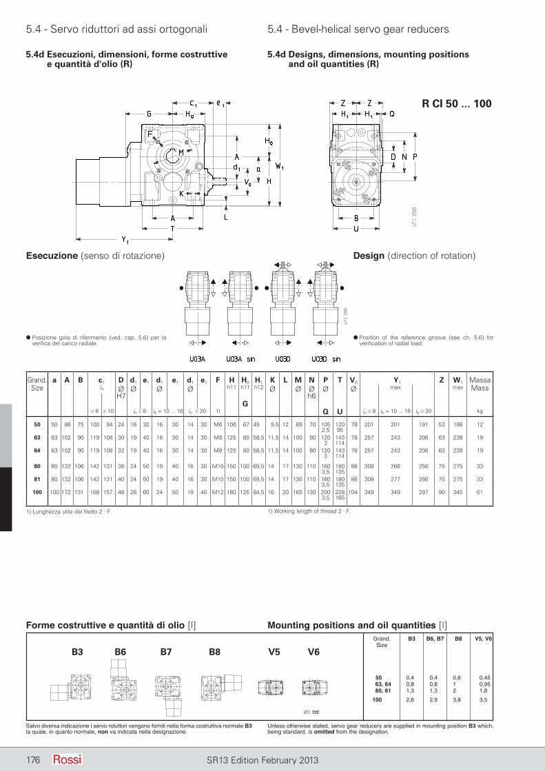
5.4 - Servo riduttori ad assi ortogonali 5.4 - Bevel-helical servo gear reducers
176 SR13 Edition February 2013
5.4d Esecuzioni, dimensioni, forme costruttive e quantità d'olio (R)
5.4d Designs, dimensions, mounting positions and oil quantities (R)
R CI 50 ... 100
1) Lunghezza utile del filetto 2 · F. 1) Working length of thread 2 · F.
d Posizione gola di riferimento (ved. cap. 5.6) per la verifica del carico radiale.
d Position of the reference groove (see ch. 5.6) for verification of radial load.
Esecuzione (senso di rotazione) Design (direction of rotation)
Forme costruttive e quantità di olio [l]
Salvo diversa indicazione i servo riduttori vengono forniti nella forma costruttiva normale B3 la quale, in quanto normale, non va indicata nella designazione.
Unless otherwise stated, servo gear reducers are supplied in mounting position B3 which, being standard, is omitted from the designation.
Mounting positions and oil quantities [l] Grand. B3 B6, B7 B8 V5, V6 Size
0 50, 1 0,40 0,40 0,60 0,45 63, 64 0,80 0,80 100, 0,95 80, 81 1,30 1,30 200, 1,80 100, 01 2,60 2,90 3,80 3,50
Grand. a A B c1 D d1 e1 d1 e1 d1 e1 F H H0 H1 K L M N P T V0 Y1 Z W1 MassaSize iN Ø Ø Ø Ø h11 h11 h12 Ø Ø Ø Ø Ø max max Mass
H7 h6G
≤ 8 ≥ 10 iN ≤ 8 iN = 10 ... 16 iN ≥ 20 1) Q U iN ≤ 8 iN = 10 ... 16 iN ≥ 20 kg
50 50 86 75 100 94 24 16 30 16 30 14 30 M6 100 67 49 9,5 12 85 70 1052,5
12095
78 201 201 191 53 188 12
63 63 102 90 119 108 30 19 40 16 30 14 30 M8 125 80 58,5 11,5 14 100 80 1203
143114
78 257 243 206 63 238 19
64 63 102 90 119 108 32 19 40 16 30 14 30 M8 125 80 58,5 11,5 14 100 80 1203
143114
78 257 243 206 63 238 19
80 80 132 106 142 131 38 24 50 19 40 16 30 M10 150 100 69,5 14 17 130 110 1603,5
180135
86 308 266 256 75 275 33
81 80 132 106 142 131 40 24 50 19 40 16 30 M10 150 100 69,5 14 17 130 110 1603,5
180135
86 308 277 266 75 275 33
100 100 172 131 168 157 48 28 60 24 50 19 40 M12 180 125 84,5 16 20 165 130 2003,5
228165
104 349 349 297 90 345 61
B3 B6 B7 B8 V5 V6
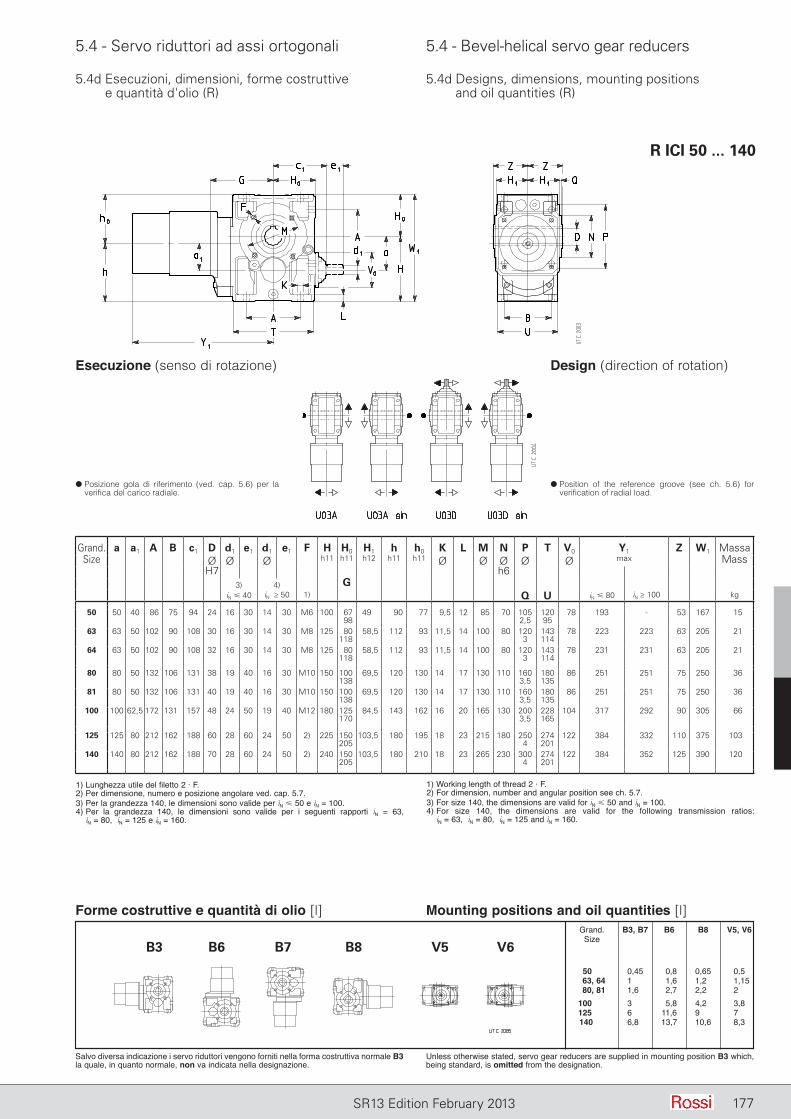
5.4 - Servo riduttori ad assi ortogonali 5.4 - Bevel-helical servo gear reducers
177SR13 Edition February 2013
5.4d Esecuzioni, dimensioni, forme costruttive e quantità d'olio (R)
5.4d Designs, dimensions, mounting positions and oil quantities (R)
R ICI 50 ... 140
d Posizione gola di riferimento (ved. cap. 5.6) per la verifica del carico radiale.
d Position of the reference groove (see ch. 5.6) for verification of radial load.
Esecuzione (senso di rotazione) Design (direction of rotation)
Forme costruttive e quantità di olio [l]
Salvo diversa indicazione i servo riduttori vengono forniti nella forma costruttiva normale B3 la quale, in quanto normale, non va indicata nella designazione.
Unless otherwise stated, servo gear reducers are supplied in mounting position B3 which, being standard, is omitted from the designation.
Mounting positions and oil quantities [l] Grand. B3, B7 B6 B8 V5, V6 Size
50, 1 0,45 0,8 0,65 0,50 63, 64 1,00 1,6 1,20 1,15 80, 81 1,60 2,7 2,20 2,00 100, 01 3,00 5,8 4,20 3,80 125, 01 6,00 11,6 9,00 70,0 140 01 6,80 13,7 10,6 8,30
B3 B6 B7 B8 V5 V6
1) Working length of thread 2 · F.2) For dimension, number and angular position see ch. 5.7.3) For size 140, the dimensions are valid for iN 50 and iN = 100.4) For size 140, the dimensions are valid for the following transmission ratios:
iN = 63, iN = 80, iN = 125 and iN = 160.
Grand. a a1 A B c1 D d1 e1 d1 e1 F H H0 H1 h h0 K L M N P T V0 Y1 Z W1 MassaSize Ø Ø Ø h11 h11 h12 h11 h11 Ø Ø Ø Ø Ø max Mass
H7 h63) 4) G
iN 40 iN ≥ 50 1) Q U iN 80 iN ≥ 100 kg
50 50 40 86 75 94 24 16 30 14 30 M6 100 6798
49 90 77 9,5 12 85 70 1052,5
12095
78 193 - 53 167 15
63 63 50 102 90 108 30 16 30 14 30 M8 125 80118
58,5 112 93 11,5 14 100 80 1203
143114
78 223 223 63 205 21
64 63 50 102 90 108 32 16 30 14 30 M8 125 80118
58,5 112 93 11,5 14 100 80 1203
143114
78 231 231 63 205 21
80 80 50 132 106 131 38 19 40 16 30 M10 150 100138
69,5 120 130 14 17 130 110 1603,5
180135
86 251 251 75 250 36
81 80 50 132 106 131 40 19 40 16 30 M10 150 100138
69,5 120 130 14 17 130 110 1603,5
180135
86 251 251 75 250 36
100 100 62,5 172 131 157 48 24 50 19 40 M12 180 125170
84,5 143 162 16 20 165 130 2003,5
228165
104 317 292 90 305 66
125 125 80 212 162 188 60 28 60 24 50 2) 225 150205
103,5 180 195 18 23 215 180 2504
274201
122 384 332 110 375 103
140 140 80 212 162 188 70 28 60 24 50 2) 240 150205
103,5 180 210 18 23 265 230 3004
274201
122 384 352 125 390 120
1) Lunghezza utile del filetto 2 · F.2) Per dimensione, numero e posizione angolare ved. cap. 5.7.3) Per la grandezza 140, le dimensioni sono valide per iN 50 e iN = 100.4) Per la grandezza 140, le dimensioni sono valide per i seguenti rapporti iN = 63,
iN = 80, iN = 125 e iN = 160.

178 SR13 Edition January 2013178 SR13 Edition February 2013
Pagina lasciata intenzionalmente biancaThis page is intentionally left blank
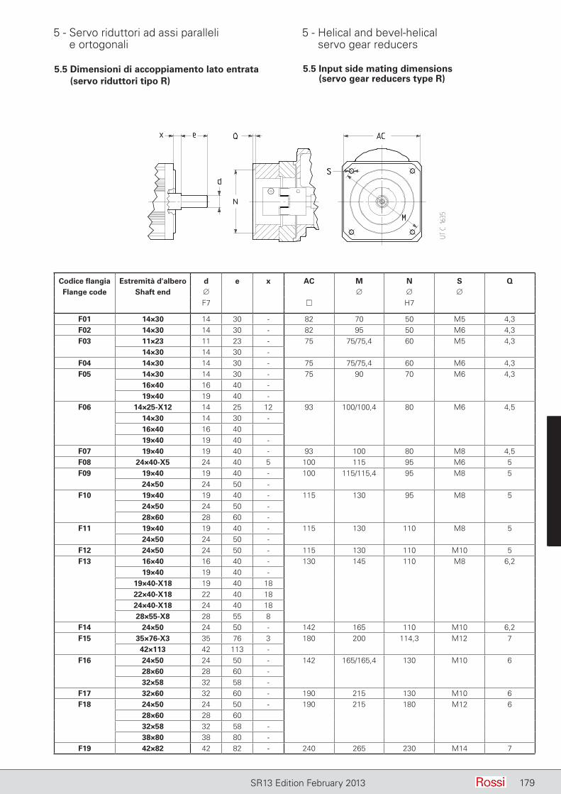
5 - Servo riduttori ad assi paralleli e ortogonali
5 - Helical and bevel-helical servo gear reducers
179SR13 Edition February 2013 179SR13 Edition February 2013 179SR12 October 2012
5.5 Dimensioni di accoppiamento lato entrata (servo riduttori tipo R)
5.5 Input side mating dimensions (servo gear reducers type R)
179SR13 Edition February 2013
Codice flangia Estremità d'albero d e x AC M N S QFlange code Shaft end ∅ ∅ ∅ ∅
F7 H7
F01 14×30 14 30 - 82 70 50 M5 4,3F02 14×30 14 30 - 82 95 50 M6 4,3F03 11×23 11 23 - 75 75/75,4 60 M5 4,3
14×30 14 30 -F04 14×30 14 30 - 75 75/75,4 60 M6 4,3F05 14×30 14 30 - 75 90 70 M6 4,3
16×40 16 40 -19×40 19 40 -
F06 14×25-X12 14 25 12 93 100/100,4 80 M6 4,514×30 14 30 -16×40 16 4019×40 19 40 -
F07 19×40 19 40 - 93 100 80 M8 4,5F08 24×40-X5 24 40 5 100 115 95 M6 5F09 19×40 19 40 - 100 115/115,4 95 M8 5
24×50 24 50 -F10 19×40 19 40 - 115 130 95 M8 5
24×50 24 50 -28×60 28 60 -
F11 19×40 19 40 - 115 130 110 M8 524×50 24 50 -
F12 24×50 24 50 - 115 130 110 M10 5F13 16×40 16 40 - 130 145 110 M8 6,2
19×40 19 40 -19×40-X18 19 40 1822×40-X18 22 40 1824×40-X18 24 40 1828×55-X8 28 55 8
F14 24×50 24 50 - 142 165 110 M10 6,2F15 35×76-X3 35 76 3 180 200 114,3 M12 7
42×113 42 113 -F16 24×50 24 50 - 142 165/165,4 130 M10 6
28×60 28 60 -32×58 32 58 -
F17 32×60 32 60 - 190 215 130 M10 6F18 24×50 24 50 - 190 215 180 M12 6
28×60 28 6032×58 32 58 -38×80 38 80 -
F19 42×82 42 82 - 240 265 230 M14 7
5 - Servo riduttori ad assi paralleli e ortogonali
5 - Helical and bevel-helical servo gear reducers
180 SR13 Edition February 2013
5.6 Carichi radiali Fr2 [N] o assiali Fa2 [N] sull'estremità d'albero lento
5.6 Radial loads Fr2 [N] or axial loads Fa2 [N] on low speed shaft end
Carichi assiali Fa2
Il valore ammissibile di Fa2 si trova nella colonna per la quale il senso di rotazione dell’albero lento (freccia bianca o freccia nera) e il sen so della forza assiale (freccia intera o freccia tratteggiata) corrispondono a quelli che si hanno sul servo riduttore. Il senso di rotazione e il senso della forza si stabiliscono guardando il servo riduttore da un punto qualunque, purché sia lo stesso per la rotazione e per la forza.Quando è possibile, mettersi nelle condizioni corrispondenti alla colonna con valori ammissibili più elevati.
Carichi radiali Fr2
Quando il collegamento tra servo riduttore e macchina è realizzato con una trasmissione che genera carichi radiali sull’estremità d’albero, è ne cessario che questi siano minori o uguali a quelli indicati in tabella.Normalmente il carico radiale sull’estremità d’albero lento assume valori rilevanti; infatti si tende a realizzare la trasmissione tra servo riduttore e macchina con elevato rapporto di riduzione (per economizzare sul servo riduttore) e con diametri piccoli (per economizzare sulla trasmissione o per esigenze d’ingombro).Evidentemente la durata e l’usura (che influisce negativamente an che sugli ingranaggi) dei cuscinetti e la resistenza dell’asse lento pongono dei limiti al carico radiale ammissibile.L’elevato valore che può assumere il carico radiale e l’importanza di non superare i valori ammissibili richiedono di sfruttare al massimo le possibilità del servo riduttore.Pertanto i carichi radiali ammessi in tabella sono in funzione: del prodotto della velocità angolare n2 [min-1] per la durata dei cuscinetti Lh [h] richiesta, del senso di rotazione, della posizione angolare [°] del carico e del momento torcente M2 [daN m] richiesto.I carichi radiali ammessi in tabella valgono per carichi agenti in mezzeria dell’estremità d’albero lento, cioè ad una distanza dalla battuta di 0,5 · E (E = lunghezza dell’estremità d’albero); se agiscono a 0,315 · E moltiplicarli per 1,25; se agiscono a 0,8 · E moltiplicarli per 0,8.
Axial loads Fa2
Permissible Fa2 is shown in the column where direction of rotation of low speed shaft (black or white arrow) and direction of the axial force (solid or broken arrow) correspond to those of the servo gear reducer in question. Direction of rotation and direction of force may be established viewing the servo gear reducer from any point, providing the same point adopted for both.Wherever possible, choose the load conditions corresponding the column with the highest admissible values.
Radial loads Fr2Radial loads generated on the shaft end by a drive connecting servo gear reducer and machine must be less than or equal to those given in the relevant table.Normally, radial loads on low speed shaft ends are considerable: in fact there is a tendency to connect the servo gear reducer to the machine by means of a transmission with high transmission ratio (economizing on the servo gear reducers) and with small diameters (economizing on the drive, and for requirements dictated by overall dimensions).Bearing life and wear (which also affect gears unfavourably) and low speed shaft strength, clearly impose limits on permissible radial load.The high value which radial load may take on, and the importance of not exceeding permissible values, make it necessary to take full advantage of the servo gear reducer's possibilities.Permissible radial loads given in the table are therefore based on: the product of speed n2 [min-1] multiplied by bearing life Lh [h] required, the direction of rotation, the angular position [°] of the load and torque M2 [daN m] required.Radial loads given in the table are valid for overhung loads on centre line of low speed shaft end, i.e. operating at a distance of 0,5 · E (E = shaft end length) from the shoulder. If operating at 0,315 · E multiply by 1,25; if operating at 0,8 · E multiply by 0,8.
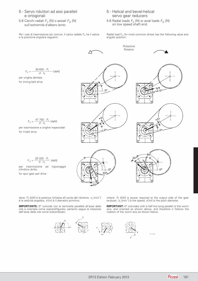
5 - Servo riduttori ad assi paralleli e ortogonali
5 - Helical and bevel-helical servo gear reducers
181SR13 Edition February 2013
5.6 Carichi radiali Fr2 [N] o assiali Fa2 [N] sull'estremità d'albero lento
5.6 Radial loads Fr2 [N] or axial loads Fa2 [N] on low speed shaft end
Per i casi di trasmissione più comuni, il carico radiale Fr2 ha il valore e la posizione angolare seguenti:
Radial load Fr2 for most common drives has the following value and angular position:
dove: P2 [kW] è la potenza richiesta all’uscita del riduttore, n2 [min-1] è la velocità angolare, d [m] è il diametro primitivo.
IMPORTANTE: 0° coincide con la semiretta parallela all’asse della vite e orientata come sopraraffigurato, pertanto segue la rotazione dell’asse della vite come sottoindicato.
where: P2 [kW] is power required at the output side of the gear re-ducer, n2 [min-1] is the speed, d [m] is the pitch diameter.
IMPORTANT: 0° coincides with a half line lying parallel to the worm axis, and oriented as shown above, and therefore it follows the rotation of the worm axis as shown below.
Fr2 = 28 650 · P2
d · n2 [daN]
per cinghia dentata
for timing belt drive
Fr2 = 47 750 · P2
d · n2 [daN]
per trasmissione a cinghie trapezoidali
for V-belt drive
Fr2 = 20 320 · P2
d · n2 [daN]
per trasmissione ad ingranaggio cilindrico diritto
for spur gear pair drive
RotazioneRotation
UT. C 914

5 - Servo riduttori ad assi paralleli e ortogonali
5 - Helical and bevel-helical servo gear reducers
182 SR13 Edition February 2013
5
5.6 Carichi radiali Fr2 [N] o assiali Fa2 [N] sull’estre mi tà d’albero lento
5.6 Radial loads Fr2 [N] or axial loads Fa2 [N] on low speed shaft end
Carico radiale applicato lato opposto gola. Applied radial load opposite side to groove.Per carichi radiali agenti contemporaneamente sui due lati interpellarci. For radial loads acting simultaneously on both sides consult us.
1) Contemporaneamente al carico radiale può agire un carico assiale fino a 0,2 volte quello di tabella e viceversa. Per valori superiori interpellarci.
1) An axial load of up to 0,2 times the value in the table is permissible, simultaneously with the radial load. If exceeded consult us.
grand. size 50 450 000 160 1 900 3 150 3 150 3 150 3 150 2 360 1 600 1 500 2 800 1 900 1 800 2 120 3 150 3 150 3 150 3 150 2 240 1 060 112 2 500 3 150 3 150 3 150 3 150 3 000 2 240 2 120 3 150 2 500 2 360 2 650 3 150 3 150 3 150 3 150 2 240 1 120 80 3 000 3 150 3 150 3 150 3 150 3 150 2 650 2 500 3 150 2 800 2 650 3 000 3 150 3 150 3 150 3 150 2 240 1 120
560 000 160 1 600 3 000 3 150 3 150 3 150 2 120 1 320 1 180 2 500 1 700 1 500 1 900 3 000 3 150 3 150 3 150 2 120 850 112 2 240 3 150 3 150 3 150 3 150 2 650 2 000 1 800 3 000 2 240 2 000 2 360 3 150 3 150 3 150 3 150 2 240 1 120 80 2 650 3 150 3 150 3 150 3 150 3 000 2 360 2 240 3 000 2 500 2 360 2 650 3 150 3 150 3 150 3 150 2 240 1 120
710 000 160 1 320 2 800 3 150 3 150 3 150 1 800 1 000 950 2 240 1 400 1 250 1 600 2 650 3 150 3 150 3 150 1 900 670 112 2 000 3 000 3 150 3 150 3 150 2 360 1 700 1 600 2 650 2 000 1 800 2 120 3 000 3 150 3 150 3 150 2 000 1 120 80 2 360 3 150 3 150 3 150 3 150 2 650 2 120 2 000 2 800 2 240 2 120 2 500 3 000 3 150 3 150 3 150 2 000 1 120
900 000 160 1 060 2 360 3 150 3 150 3 150 1 400 800 710 1 900 1 120 1 000 1 320 2 360 3 150 3 150 3 150 1 700 450 112 1 700 2 800 3 150 3 150 3 150 2 120 1 500 1 320 2 360 1 700 1 600 1 900 2 650 3 150 3 150 3 150 1 800 900 80 2 120 3 000 3 150 3 150 3 150 2 360 1 900 1 800 2 650 2 120 1 900 2 240 2 800 3 150 3 150 3 150 1 800 1 120
1 120 000 160 710 2 000 3 150 3 150 3 000 1 060 500 450 1 700 950 800 1 060 2 120 3 150 3 150 3 150 1 600 315 112 1 500 2 500 3 150 3 150 3 150 1 900 1 250 1 180 2 120 1 500 1 400 1 700 2 500 3 150 3 150 3 150 1 600 750 80 1 900 2 650 3 150 3 150 3 000 2 240 1 700 1 600 2 360 1 900 1 700 2 000 2 650 3 150 3 150 3 150 1 700 1 060
1 400 000 112 1 320 2 240 3 150 3 150 3 000 1 600 1 060 950 1 900 1 320 1 180 1 500 2 240 3 150 3 150 3 000 1 500 600 80 1 700 2 500 3 150 3 150 2 800 2 000 1 500 1 400 2 120 1 700 1 500 1 800 2 360 3 150 3 150 3 000 1 500 900 56 2 000 2 500 3 000 3 150 2 800 2 240 1 800 1 800 2 240 2 000 1 900 2 000 2 500 3 000 3 000 2 800 1 600 1 120
1 800 000 112 1 060 2 000 3 150 3 150 2 650 1 400 800 750 1 700 1 120 950 1 250 2 000 3 150 3 150 2 800 1 320 450 80 1 500 2 240 3 150 3 150 2 650 1 800 1 250 1 180 1 900 1 500 1 320 1 600 2 240 3 000 3 150 2 650 1 400 710 56 1 800 2 360 2 800 3 000 2 500 2 000 1 600 1 500 2 120 1 700 1 600 1 800 2 240 2 800 3 000 2 650 1 400 950
2 240 000 112 850 1 800 3 150 3 150 2 500 1 120 670 600 1 500 900 800 1 060 1 800 3 000 3 150 2 650 1 250 335 80 1 320 2 120 3 000 3 150 2 500 1 600 1 120 1 060 1 800 1 320 1 180 1 400 2 000 2 800 3 000 2 500 1 250 600 56 1 600 2 120 2 650 2 800 2 360 1 800 1 400 1 400 1 900 1 600 1 500 1 700 2 120 2 650 2 800 2 500 1 250 800
2 800 000 80 1 180 2 000 3 000 3 000 2 360 1 400 1 000 850 1 600 1 120 1 060 1 250 1 900 2 650 2 800 2 500 1 120 500 56 1 500 2 000 2 500 2 650 2 240 1 700 1 320 1 250 1 800 1 500 1 320 1 500 2 000 2 500 2 650 2 360 1 180 710
max 3 150 max 2 240 max 1 120
grand. size 40 n2 · Lh M2 Fr2
1) Fa21)
min-1 · h N m 0 45 90 135 180 225 270 315 0 45 90 135 180 225 270 315 355 000 80 2 240 2 240 2 240 2 240 2 240 2 240 2 240 2 240 2 240 2 240 2 240 2 240 2 240 2 240 2 240 2 240 800 1 600 56 2 240 2 240 2 240 2 240 2 240 2 240 2 240 2 240 2 240 2 240 2 240 2 240 2 240 2 240 2 240 2 240 800 1 600 40 2 240 2 240 2 240 2 240 2 240 2 240 2 240 2 240 2 240 2 240 2 240 2 240 2 240 2 240 2 240 2 240 800 1 600
450 000 80 2 240 2 240 2 240 2 240 2 240 2 240 2 240 2 240 2 240 2 120 2 240 2 240 2 240 2 240 2 240 2 240 800 1 600 56 2 240 2 240 2 240 2 240 2 240 2 240 2 240 2 240 2 240 2 240 2 240 2 240 2 240 2 240 2 240 2 240 800 1 600 40 2 240 2 240 2 240 2 240 2 240 2 240 2 240 2 240 2 240 2 240 2 240 2 240 2 240 2 240 2 240 2 240 800 1 600
560 000 80 2 240 2 240 2 240 2 240 2 240 2 120 2 120 2 240 2 120 2 000 2 120 2 240 2 240 2 240 2 240 2 240 800 1 600 56 2 240 2 240 2 240 2 240 2 240 2 240 2 240 2 240 2 240 2 120 2 240 2 240 2 240 2 240 2 240 2 240 800 1 600 40 2 240 2 240 2 240 2 240 2 240 2 240 2 240 2 240 2 240 2 240 2 240 2 240 2 240 2 240 2 240 2 240 800 1 600
710 000 80 2 240 2 240 2 240 2 240 2 240 2 000 1 900 2 000 1 900 1 800 1 900 2 240 2 240 2 240 2 240 2 240 710 1 500 56 2 240 2 240 2 240 2 240 2 240 2 000 2 000 2 120 2 000 1 900 2 000 2 240 2 240 2 240 2 240 2 240 800 1 600 40 2 240 2 240 2 240 2 240 2 240 2 120 2 120 2 240 2 120 2 000 2 120 2 240 2 240 2 240 2 240 2 240 800 1 600
900 000 80 2 120 2 240 2 000 1 900 2 000 1 800 1 700 1 900 1 700 1 600 1 700 2 000 2 240 2 240 2 240 2 120 530 1 320 56 2 120 2 240 2 240 2 240 2 000 1 900 1 900 2 000 1 800 1 700 1 800 2 120 2 240 2 240 2 240 2 120 800 1 400 40 2 120 2 240 2 240 2 240 2 120 2 000 1 900 2 000 1 900 1 900 1 900 2 120 2 240 2 240 2 240 2 120 800 1 500
1 120 000 80 2 000 2 360 1 500 1 400 1 900 1 600 1 600 1 700 1 600 1 400 1 500 1 900 2 240 2 000 1 900 1 900 400 1 180 56 2 000 2 240 2 240 2 120 1 900 1 700 1 700 1 800 1 700 1 600 1 700 1 900 2 240 2 240 2 240 2 000 710 1 250 40 2 000 2 120 2 120 2 120 1 900 1 800 1 800 1 900 1 800 1 700 1 800 2 000 2 120 2 240 2 120 2 000 800 1 320
1 400 000 56 1 900 2 120 2 120 2 000 1 800 1 600 1 600 1 700 1 600 1 500 1 500 1 800 2 120 2 240 2 120 1 800 560 1 180 40 1 900 2 000 2 000 1 900 1 800 1 700 1 600 1 700 1 600 1 600 1 600 1 800 2 000 2 120 2 000 1 800 800 1 180 28 1 900 2 000 2 000 1 900 1 800 1 700 1 700 1 800 1 700 1 600 1 700 1 800 2 000 2 000 2 000 1 800 800 1 320
1 800 000 56 1 700 1 900 2 000 1 800 1 600 1 400 1 400 1 500 1 400 1 320 1 400 1 600 1 900 2 120 1 900 1 700 475 1 000 40 1 700 1 900 1 900 1 800 1 600 1 500 1 500 1 600 1 500 1 400 1 500 1 700 1 900 2 000 1 900 1 700 670 1 120 28 1 700 1 800 1 800 1 800 1 700 1 600 1 600 1 600 1 600 1 500 1 500 1 700 1 800 1 900 1 800 1 700 800 1 120
2 240 000 56 1 600 1 800 1 600 1 500 1 500 1 320 1 320 1 400 1 320 1 180 1 250 1 500 1 800 1 900 1 800 1 500 355 900 40 1 600 1 700 1 800 1 700 1 500 1 400 1 400 1 500 1 400 1 320 1 400 1 500 1 700 1 800 1 800 1 600 560 950 28 1 600 1 700 1 700 1 600 1 500 1 500 1 400 1 500 1 400 1 400 1 400 1 600 1 700 1 800 1 700 1 600 710 1 060
2 800 000 40 1 500 1 600 1 700 1 600 1 400 1 320 1 250 1 320 1 250 1 180 1 250 1 400 1 600 1 700 1 600 1 400 500 850 28 1 500 1 600 1 600 1 500 1 400 1 320 1 320 1 400 1 320 1 250 1 320 1 400 1 600 1 700 1 600 1 500 630 900
max 2 240 max 800 max 1 600
UT.
C 9
15
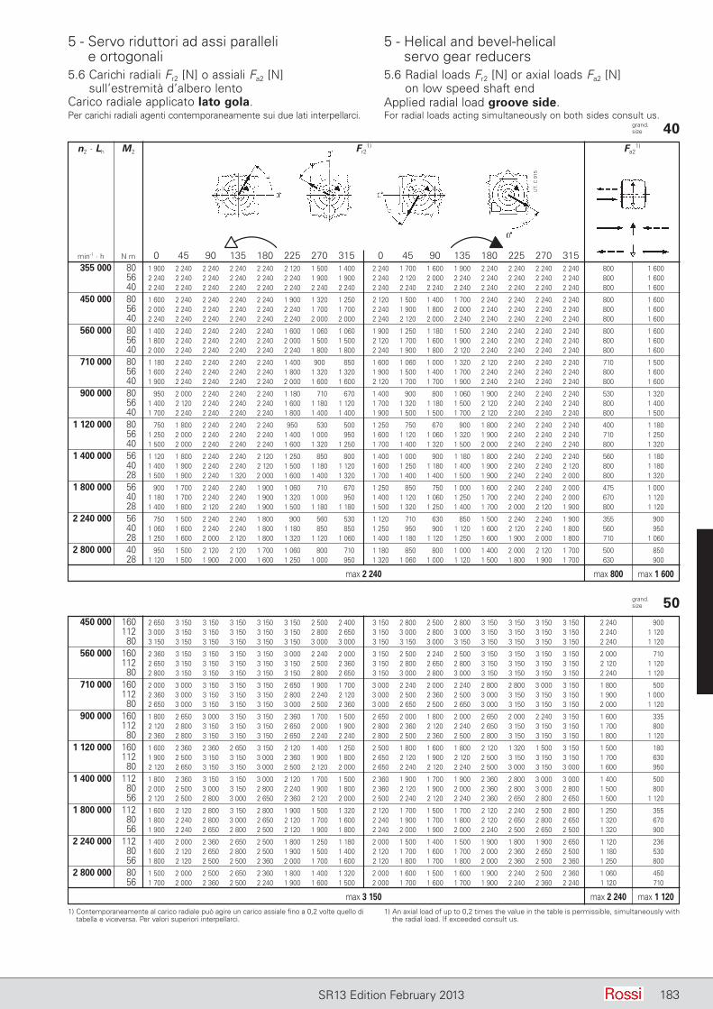
5 - Servo riduttori ad assi paralleli e ortogonali
5 - Helical and bevel-helical servo gear reducers
183SR13 Edition February 2013
1) Contemporaneamente al carico radiale può agire un carico assiale fino a 0,2 volte quello di tabella e viceversa. Per valori superiori interpellarci.
1) An axial load of up to 0,2 times the value in the table is permissible, simultaneously with the radial load. If exceeded consult us.
grand. size 50 450 000 160 2 650 3 150 3 150 3 150 3 150 3 150 2 500 2 400 3 150 2 800 2 500 2 800 3 150 3 150 3 150 3 150 2 240 900 112 3 000 3 150 3 150 3 150 3 150 3 150 2 800 2 650 3 150 3 000 2 800 3 000 3 150 3 150 3 150 3 150 2 240 1 120 80 3 150 3 150 3 150 3 150 3 150 3 150 3 000 3 000 3 150 3 150 3 000 3 150 3 150 3 150 3 150 3 150 2 240 1 120
560 000 160 2 360 3 150 3 150 3 150 3 150 3 000 2 240 2 000 3 150 2 500 2 240 2 500 3 150 3 150 3 150 3 150 2 000 710 112 2 650 3 150 3 150 3 150 3 150 3 150 2 500 2 360 3 150 2 800 2 650 2 800 3 150 3 150 3 150 3 150 2 120 1 120 80 2 800 3 150 3 150 3 150 3 150 3 150 2 800 2 650 3 150 3 000 2 800 3 000 3 150 3 150 3 150 3 150 2 240 1 120
710 000 160 2 000 3 000 3 150 3 150 3 150 2 650 1 900 1 700 3 000 2 240 2 000 2 240 2 800 2 800 3 000 3 150 1 800 500 112 2 360 3 000 3 150 3 150 3 150 2 800 2 240 2 120 3 000 2 500 2 360 2 500 3 000 3 150 3 150 3 150 1 900 1 000 80 2 650 3 000 3 150 3 150 3 150 3 000 2 500 2 360 3 000 2 650 2 500 2 650 3 000 3 150 3 150 3 150 2 000 1 120
900 000 160 1 800 2 650 3 000 3 150 3 150 2 360 1 700 1 500 2 650 2 000 1 800 2 000 2 650 2 000 2 240 3 150 1 600 335 112 2 120 2 800 3 150 3 150 3 150 2 650 2 000 1 900 2 800 2 360 2 120 2 240 2 650 3 150 3 150 3 150 1 700 800 80 2 360 2 800 3 150 3 150 3 150 2 650 2 240 2 240 2 800 2 500 2 360 2 500 2 800 3 150 3 150 3 150 1 800 1 120
1 120 000 160 1 600 2 360 2 360 2 650 3 150 2 120 1 400 1 250 2 500 1 800 1 600 1 800 2 120 1 320 1 500 3 150 1 500 180 112 1 900 2 500 3 150 3 150 3 000 2 360 1 900 1 800 2 650 2 120 1 900 2 120 2 500 3 150 3 150 3 150 1 700 630 80 2 120 2 650 3 150 3 150 3 000 2 500 2 120 2 000 2 650 2 240 2 120 2 240 2 500 3 000 3 150 3 000 1 600 950
1 400 000 112 1 800 2 360 3 150 3 150 3 000 2 120 1 700 1 500 2 360 1 900 1 700 1 900 2 360 2 800 3 000 3 000 1 400 500 80 2 000 2 500 3 000 3 150 2 800 2 240 1 900 1 800 2 360 2 120 1 900 2 000 2 360 2 800 3 000 2 800 1 500 800 56 2 120 2 500 2 800 3 000 2 650 2 360 2 120 2 000 2 500 2 240 2 120 2 240 2 360 2 650 2 800 2 650 1 500 1 120
1 800 000 112 1 600 2 120 2 800 3 150 2 800 1 900 1 500 1 320 2 120 1 700 1 500 1 700 2 120 2 240 2 500 2 800 1 250 355 80 1 800 2 240 2 800 3 000 2 650 2 120 1 700 1 600 2 240 1 900 1 700 1 800 2 120 2 650 2 800 2 650 1 320 670 56 1 900 2 240 2 650 2 800 2 500 2 120 1 900 1 800 2 240 2 000 1 900 2 000 2 240 2 500 2 650 2 500 1 320 900
2 240 000 112 1 400 2 000 2 360 2 650 2 500 1 800 1 250 1 180 2 000 1 500 1 400 1 500 1 900 1 800 1 900 2 650 1 120 236 80 1 600 2 120 2 650 2 800 2 500 1 900 1 500 1 400 2 120 1 700 1 600 1 700 2 000 2 360 2 650 2 500 1 180 530 56 1 800 2 120 2 500 2 500 2 360 2 000 1 700 1 600 2 120 1 800 1 700 1 800 2 000 2 360 2 500 2 360 1 250 800
2 800 000 80 1 500 2 000 2 500 2 650 2 360 1 800 1 400 1 320 2 000 1 600 1 500 1 600 1 900 2 240 2 500 2 360 1 060 450 56 1 700 2 000 2 360 2 500 2 240 1 900 1 600 1 500 2 000 1 700 1 600 1 700 1 900 2 240 2 360 2 240 1 120 710
max 3 150 max 2 240 max 1 120
grand. size 40 n2 · Lh M2 Fr2
1) Fa21)
min-1 · h N m 0 45 90 135 180 225 270 315 0 45 90 135 180 225 270 315 355 000 80 1 900 2 240 2 240 2 240 2 240 2 120 1 500 1 400 2 240 1 700 1 600 1 900 2 240 2 240 2 240 2 240 800 1 600 56 2 240 2 240 2 240 2 240 2 240 2 240 1 900 1 900 2 240 2 120 2 000 2 240 2 240 2 240 2 240 2 240 800 1 600 40 2 240 2 240 2 240 2 240 2 240 2 240 2 240 2 240 2 240 2 240 2 240 2 240 2 240 2 240 2 240 2 240 800 1 600
450 000 80 1 600 2 240 2 240 2 240 2 240 1 900 1 320 1 250 2 120 1 500 1 400 1 700 2 240 2 240 2 240 2 240 800 1 600 56 2 000 2 240 2 240 2 240 2 240 2 240 1 700 1 700 2 240 1 900 1 800 2 000 2 240 2 240 2 240 2 240 800 1 600 40 2 240 2 240 2 240 2 240 2 240 2 240 2 000 2 000 2 240 2 120 2 000 2 240 2 240 2 240 2 240 2 240 800 1 600
560 000 80 1 400 2 240 2 240 2 240 2 240 1 600 1 060 1 060 1 900 1 250 1 180 1 500 2 240 2 240 2 240 2 240 800 1 600 56 1 800 2 240 2 240 2 240 2 240 2 000 1 500 1 500 2 120 1 700 1 600 1 900 2 240 2 240 2 240 2 240 800 1 600 40 2 000 2 240 2 240 2 240 2 240 2 240 1 800 1 800 2 240 1 900 1 800 2 120 2 240 2 240 2 240 2 240 800 1 600
710 000 80 1 180 2 240 2 240 2 240 2 240 1 400 900 850 1 600 1 060 1 000 1 320 2 120 2 240 2 240 2 240 710 1 500 56 1 600 2 240 2 240 2 240 2 240 1 800 1 320 1 320 1 900 1 500 1 400 1 700 2 240 2 240 2 240 2 240 800 1 600 40 1 900 2 240 2 240 2 240 2 240 2 000 1 600 1 600 2 120 1 700 1 700 1 900 2 240 2 240 2 240 2 240 800 1 600
900 000 80 950 2 000 2 240 2 240 2 240 1 180 710 670 1 400 900 800 1 060 1 900 2 240 2 240 2 240 530 1 320 56 1 400 2 120 2 240 2 240 2 240 1 600 1 180 1 120 1 700 1 320 1 180 1 500 2 120 2 240 2 240 2 240 800 1 400 40 1 700 2 240 2 240 2 240 2 240 1 800 1 400 1 400 1 900 1 500 1 500 1 700 2 120 2 240 2 240 2 240 800 1 500
1 120 000 80 750 1 800 2 240 2 240 2 240 950 530 500 1 250 750 670 900 1 800 2 240 2 240 2 240 400 1 180 56 1 250 2 000 2 240 2 240 2 240 1 400 1 000 950 1 600 1 120 1 060 1 320 1 900 2 240 2 240 2 240 710 1 250 40 1 500 2 000 2 240 2 240 2 240 1 600 1 320 1 250 1 700 1 400 1 320 1 500 2 000 2 240 2 240 2 240 800 1 320
1 400 000 56 1 120 1 800 2 240 2 240 2 120 1 250 850 800 1 400 1 000 900 1 180 1 800 2 240 2 240 2 240 560 1 180 40 1 400 1 900 2 240 2 240 2 120 1 500 1 180 1 120 1 600 1 250 1 180 1 400 1 900 2 240 2 240 2 120 800 1 180 28 1 500 1 900 2 240 1 320 2 000 1 600 1 400 1 320 1 700 1 400 1 400 1 500 1 900 2 240 2 240 2 000 800 1 320
1 800 000 56 900 1 700 2 240 2 240 1 900 1 060 710 670 1 250 850 750 1 000 1 600 2 240 2 240 2 000 475 1 000 40 1 180 1 700 2 240 2 240 1 900 1 320 1 000 950 1 400 1 120 1 060 1 250 1 700 2 240 2 240 2 000 670 1 120 28 1 400 1 800 2 120 2 240 1 900 1 500 1 180 1 180 1 500 1 320 1 250 1 400 1 700 2 000 2 120 1 900 800 1 120
2 240 000 56 750 1 500 2 240 2 240 1 800 900 560 530 1 120 710 630 850 1 500 2 240 2 240 1 900 355 900 40 1 060 1 600 2 240 2 240 1 800 1 180 850 850 1 250 950 900 1 120 1 600 2 120 2 240 1 800 560 950 28 1 250 1 600 2 000 2 120 1 800 1 320 1 120 1 060 1 400 1 180 1 120 1 250 1 600 1 900 2 000 1 800 710 1 060
2 800 000 40 950 1 500 2 120 2 120 1 700 1 060 800 710 1 180 850 800 1 000 1 400 2 000 2 120 1 700 500 850 28 1 120 1 500 1 900 2 000 1 600 1 250 1 000 950 1 320 1 060 1 000 1 120 1 500 1 800 1 900 1 700 630 900
max 2 240 max 800 max 1 600
UT.
C 9
15
Carico radiale applicato lato gola. Applied radial load groove side.Per carichi radiali agenti contemporaneamente sui due lati interpellarci. For radial loads acting simultaneously on both sides consult us.
5.6 Carichi radiali Fr2 [N] o assiali Fa2 [N] sull’estre mi tà d’albero lento
5.6 Radial loads Fr2 [N] or axial loads Fa2 [N] on low speed shaft end
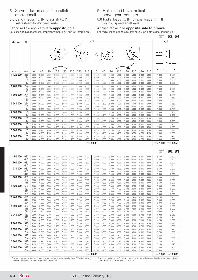
5 - Servo riduttori ad assi paralleli e ortogonali
5 - Helical and bevel-helical servo gear reducers
184 SR13 Edition February 2013
grand. size 63, 64 n2 · Lh M2 Fr2
1) Fa21)
min-1 · h N m 0 45 90 135 180 225 270 315 0 45 90 135 180 225 270 315 1 120 000 315 5 000 5 000 5 000 5 000 5 000 5 000 5 000 5 000 5 000 5 000 5 000 5 000 5 000 5 000 5 000 5 000 1 800 3 550 224 5 000 5 000 5 000 5 000 5 000 5 000 5 000 5 000 5 000 5 000 5 000 5 000 5 000 5 000 5 000 5 000 1 800 3 550 160 5 000 5 000 5 000 5 000 5 000 5 000 5 000 5 000 5 000 5 000 5 000 5 000 5 000 5 000 5 000 5 000 1 800 3 550 112 5 000 5 000 5 000 5 000 5 000 5 000 5 000 5 000 5 000 5 000 5 000 5 000 5 000 5 000 5 000 5 000 1 800 3 550
1 400 000 224 5 000 5 000 5 000 5 000 5 000 5 000 5 000 5 000 5 000 5 000 5 000 5 000 5 000 5 000 5 000 5 000 1 800 3 550 160 5 000 5 000 5 000 5 000 5 000 5 000 5 000 5 000 5 000 5 000 5 000 5 000 5 000 5 000 5 000 5 000 1 800 3 550 112 5 000 5 000 5 000 5 000 5 000 5 000 5 000 5 000 5 000 5 000 5 000 5 000 5 000 5 000 5 000 5 000 1 800 3 550
1 800 000 224 5 000 5 000 5 000 5 000 5 000 5 000 5 000 5 000 5 000 5 000 5 000 5 000 5 000 5 000 5 000 5 000 1 800 3 550 160 5 000 5 000 5 000 5 000 5 000 5 000 5 000 5 000 5 000 5 000 5 000 5 000 5 000 5 000 5 000 5 000 1 800 3 550 112 5 000 5 000 5 000 5 000 5 000 5 000 5 000 5 000 5 000 5 000 5 000 5 000 5 000 5 000 5 000 5 000 1 800 3 550
2 240 000 224 5 000 5 000 5 000 5 000 5 000 5 000 5 000 5 000 4 750 4 500 5 000 5 000 5 000 5 000 5 000 5 000 1 800 3 350 160 5 000 5 000 5 000 5 000 5 000 5 000 5 000 5 000 5 000 5 000 5 000 5 000 5 000 5 000 5 000 5 000 1 800 3 350 112 5 000 5 000 5 000 5 000 5 000 5 000 5 000 5 000 5 000 5 000 5 000 5 000 5 000 5 000 5 000 5 000 1 800 3 350
2 800 000 160 5 000 5 000 5 000 5 000 5 000 4 750 4 750 5 000 4 750 4 500 4 750 5 000 5 000 5 000 5 000 5 000 1 800 3 150 112 5 000 5 000 5 000 5 000 5 000 5 000 5 000 5 000 5 000 4 750 5 000 5 000 5 000 5 000 5 000 5 000 1 800 3 150
3 550 000 160 5 000 5 000 5 000 5 000 4 750 4 500 4 500 4 750 4 250 4 250 4 250 5 000 5 000 5 000 5 000 4 750 1 800 3 000 112 5 000 5 000 5 000 5 000 4 750 4 500 4 500 4 750 4 500 4 500 4 500 5 000 5 000 5 000 5 000 5 000 1 800 3 000
4 500 000 160 4 750 5 000 5 000 4 750 4 500 4 000 4 000 4 250 4 000 3 750 4 000 4 500 5 000 5 000 5 000 4 500 1 800 2 800 112 4 750 5 000 5 000 4 750 4 500 4 250 4 250 4 500 4 250 4 000 4 250 4 500 5 000 5 000 5 000 4 500 1 800 2 800
5 600 000 160 4 500 4 750 4 750 4 500 4 000 3 750 3 750 4 000 3 750 3 550 3 750 4 250 4 750 5 000 4 750 4 250 1 600 2 650 112 4 500 4 750 4 750 4 500 4 250 4 000 4 000 4 000 3 750 3 750 4 000 4 250 4 750 4 750 4 750 4 250 1 800 2 650
7 100 000 160 4 000 4 500 4 250 4 000 3 750 3 550 3 550 3 750 3 350 3 150 3 350 4 000 4 500 4 750 4 500 3 750 1 400 2 360 112 4 000 4 250 4 250 4 250 3 750 3 750 3 550 3 750 3 550 3 550 3 550 4 000 4 250 4 500 4 250 4 000 1 800 2 360
max 5 000 max 1 800 max 3 550
grand. size 80, 81 450 000 630 8 000 8 000 8 000 8 000 8 000 8 000 8 000 8 000 8 000 8 000 8 000 8 000 8 000 8 000 8 000 8 000 5 600 2 800 450 8 000 8 000 8 000 8 000 8 000 8 000 8 000 8 000 8 000 8 000 8 000 8 000 8 000 8 000 8 000 8 000 5 600 2 800
560 000 630 8 000 8 000 8 000 8 000 8 000 8 000 8 000 7 500 8 000 8 000 8 000 8 000 8 000 8 000 8 000 8 000 5 600 2 800 450 8 000 8 000 8 000 8 000 8 000 8 000 8 000 8 000 8 000 8 000 8 000 8 000 8 000 8 000 8 000 8 000 5 600 2 800
710 000 630 7 500 8 000 8 000 8 000 8 000 8 000 7 500 7 100 8 000 8 000 7 500 7 500 8 000 8 000 8 000 8 000 5 600 2 800 450 8 000 8 000 8 000 8 000 8 000 8 000 8 000 7 500 8 000 8 000 8 000 8 000 8 000 8 000 8 000 8 000 5 600 2 800 315 8 000 8 000 8 000 8 000 8 000 8 000 8 000 8 000 8 000 8 000 8 000 8 000 8 000 8 000 8 000 8 000 5 600 2 800
900 000 630 6 700 8 000 8 000 8 000 8 000 8 000 6 700 6 300 8 000 7 500 7 100 7 100 7 100 7 500 8 000 8 000 5 300 2 650 450 7 500 8 000 8 000 8 000 8 000 8 000 7 500 7 100 8 000 8 000 7 500 7 500 8 000 8 000 8 000 8 000 5 600 2 800 315 7 500 8 000 8 000 8 000 8 000 8 000 8 000 7 500 8 000 8 000 8 000 8 000 8 000 8 000 8 000 8 000 5 600 2 800
1 120 000 630 6 300 7 100 7 500 8 000 8 000 8 000 6 300 5 600 8 000 7 100 6 300 6 700 6 300 6 700 7 500 8 000 5 000 2 360 450 6 700 8 000 8 000 8 000 8 000 8 000 6 700 6 300 8 000 7 500 7 100 7 100 7 500 8 000 8 000 8 000 5 000 2 800 315 7 100 8 000 8 000 8 000 8 000 8 000 7 100 7 100 8 000 7 500 7 500 7 500 8 000 8 000 8 000 8 000 5 300 2 800 224 7 500 8 000 8 000 8 000 8 000 8 000 7 500 7 100 8 000 8 000 7 500 7 500 8 000 8 000 8 000 8 000 5 300 2 800
1 400 000 450 6 300 7 500 8 000 8 000 8 000 7 500 6 300 6 000 8 000 7 100 6 300 6 300 7 100 7 500 8 000 8 000 4 750 2 800 315 6 700 7 500 8 000 8 000 8 000 7 500 6 700 6 300 8 000 7 100 6 700 6 700 7 100 8 000 8 000 8 000 5 000 2 800 224 7 100 7 500 8 000 8 000 8 000 7 500 7 100 6 700 7 500 7 100 7 100 7 100 7 500 8 000 8 000 8 000 5 000 2 800
1 800 000 450 5 600 6 700 7 500 8 000 8 000 6 700 5 600 5 300 7 500 6 300 6 000 6 000 6 300 6 700 7 100 8 000 4 250 2 500 315 6 000 6 700 7 500 8 000 8 000 7 100 6 300 6 000 7 100 6 700 6 300 6 300 6 700 7 500 8 000 7 500 4 500 2 800 224 6 300 7 100 7 500 8 000 7 500 7 100 6 300 6 300 7 100 6 700 6 300 6 300 6 700 7 100 7 500 7 500 4 500 2 800
2 240 000 450 5 300 6 300 6 700 7 500 7 500 6 300 5 300 5 000 6 700 6 000 5 300 5 600 5 600 6 000 6 700 7 100 4 000 2 240 315 5 600 6 300 7 500 7 500 7 500 6 300 5 600 5 300 6 700 6 300 5 600 5 600 6 300 7 100 7 500 7 500 4 250 2 800 224 6 000 6 300 7 100 7 500 7 100 6 700 6 000 5 600 6 700 6 300 6 000 6 000 6 300 6 700 7 100 7 100 4 250 2 800
2 800 000 315 5 300 6 000 6 700 7 500 7 100 6 000 5 300 5 000 6 300 5 600 5 300 5 300 6 000 6 300 6 700 6 700 4 000 2 650 224 5 600 6 000 6 700 7 100 6 700 6 000 5 600 5 300 6 300 6 000 5 600 5 600 6 000 6 300 6 700 6 700 4 000 2 800
3 550 000 315 4 750 5 600 6 300 6 700 6 700 5 600 5 000 4 500 6 000 5 300 5 000 5 000 5 300 5 600 6 300 6 300 3 550 2 360 224 5 000 5 600 6 300 6 700 6 300 5 600 5 000 5 000 6 000 5 300 5 300 5 300 5 600 6 000 6 300 6 300 3 750 2 800
4 500 000 315 4 500 5 300 5 600 6 300 6 300 5 300 4 500 4 250 5 600 5 000 4 500 4 500 5 000 5 300 5 600 6 000 3 350 2 000 224 4 750 5 300 6 000 6 300 6 000 5 300 4 750 4 500 5 600 5 000 4 750 4 750 5 000 5 600 6 000 6 000 3 350 2 500
5 600 000 315 4 000 4 750 5 300 5 600 5 600 5 000 4 000 3 750 5 300 4 500 4 250 4 250 4 500 4 750 5 300 5 600 3 150 1 800 224 4 250 5 000 5 600 5 600 5 600 5 000 4 500 4 250 5 000 4 750 4 500 4 500 4 750 5 300 5 600 5 600 3 150 2 240
7 100 000 315 3 750 4 500 4 750 5 300 5 300 4 500 3 750 3 550 4 750 4 250 3 750 4 000 4 000 4 250 4 750 5 300 2 800 1 600 224 4 000 4 500 5 300 5 600 5 300 4 500 4 000 3 750 4 750 4 250 4 000 4 000 4 500 5 000 5 300 5 300 3 000 2 000
max 8 000 max 5 600 max 2 8001) Contemporaneamente al carico radiale può agire un carico assiale fino a 0,2 volte quello di
tabella e viceversa. Per valori superiori interpellarci.1) An axial load of up to 0,2 times the value in the table is permissible, simultaneously with
the radial load. If exceeded consult us.
UT.
C 9
15
Carico radiale applicato lato opposto gola. Applied radial load opposite side to groove.Per carichi radiali agenti contemporaneamente sui due lati interpellarci. For radial loads acting simultaneously on both sides consult us.
5
5.6 Carichi radiali Fr2 [N] o assiali Fa2 [N] sull’estre mi tà d’albero lento
5.6 Radial loads Fr2 [N] or axial loads Fa2 [N] on low speed shaft end
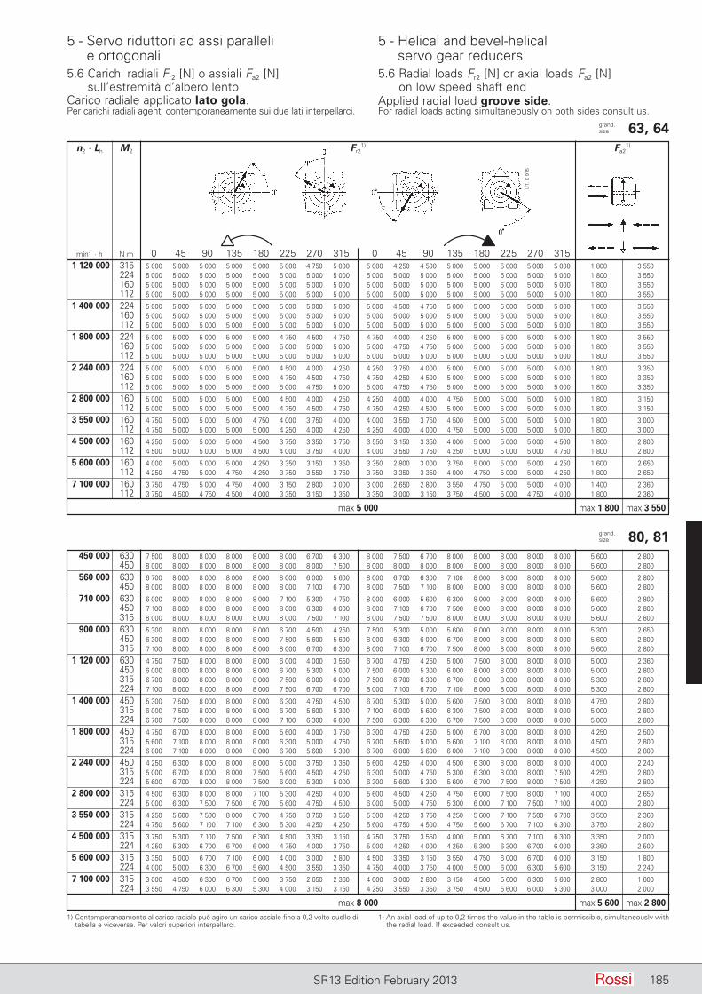
5 - Servo riduttori ad assi paralleli e ortogonali
5 - Helical and bevel-helical servo gear reducers
185SR13 Edition February 2013
grand. size 63, 64 n2 · Lh M2 Fr2
1) Fa21)
min-1 · h N m 0 45 90 135 180 225 270 315 0 45 90 135 180 225 270 315 1 120 000 315 5 000 5 000 5 000 5 000 5 000 5 000 4 750 5 000 5 000 4 250 4 500 5 000 5 000 5 000 5 000 5 000 1 800 3 550 224 5 000 5 000 5 000 5 000 5 000 5 000 5 000 5 000 5 000 5 000 5 000 5 000 5 000 5 000 5 000 5 000 1 800 3 550 160 5 000 5 000 5 000 5 000 5 000 5 000 5 000 5 000 5 000 5 000 5 000 5 000 5 000 5 000 5 000 5 000 1 800 3 550 112 5 000 5 000 5 000 5 000 5 000 5 000 5 000 5 000 5 000 5 000 5 000 5 000 5 000 5 000 5 000 5 000 1 800 3 550
1 400 000 224 5 000 5 000 5 000 5 000 5 000 5 000 5 000 5 000 5 000 4 500 4 750 5 000 5 000 5 000 5 000 5 000 1 800 3 550 160 5 000 5 000 5 000 5 000 5 000 5 000 5 000 5 000 5 000 5 000 5 000 5 000 5 000 5 000 5 000 5 000 1 800 3 550 112 5 000 5 000 5 000 5 000 5 000 5 000 5 000 5 000 5 000 5 000 5 000 5 000 5 000 5 000 5 000 5 000 1 800 3 550
1 800 000 224 5 000 5 000 5 000 5 000 5 000 4 750 4 500 4 750 4 750 4 000 4 250 5 000 5 000 5 000 5 000 5 000 1 800 3 550 160 5 000 5 000 5 000 5 000 5 000 5 000 5 000 5 000 5 000 4 750 4 750 5 000 5 000 5 000 5 000 5 000 1 800 3 550 112 5 000 5 000 5 000 5 000 5 000 5 000 5 000 5 000 5 000 5 000 5 000 5 000 5 000 5 000 5 000 5 000 1 800 3 550
2 240 000 224 5 000 5 000 5 000 5 000 5 000 4 500 4 000 4 250 4 250 3 750 4 000 5 000 5 000 5 000 5 000 5 000 1 800 3 350 160 5 000 5 000 5 000 5 000 5 000 4 750 4 500 4 750 4 750 4 250 4 500 5 000 5 000 5 000 5 000 5 000 1 800 3 350 112 5 000 5 000 5 000 5 000 5 000 5 000 4 750 5 000 5 000 4 750 4 750 5 000 5 000 5 000 5 000 5 000 1 800 3 350
2 800 000 160 5 000 5 000 5 000 5 000 5 000 4 500 4 000 4 250 4 250 4 000 4 000 4 750 5 000 5 000 5 000 5 000 1 800 3 150 112 5 000 5 000 5 000 5 000 5 000 4 750 4 500 4 750 4 750 4 250 4 500 5 000 5 000 5 000 5 000 5 000 1 800 3 150
3 550 000 160 4 750 5 000 5 000 5 000 4 750 4 000 3 750 4 000 4 000 3 550 3 750 4 500 5 000 5 000 5 000 5 000 1 800 3 000 112 4 750 5 000 5 000 5 000 5 000 4 250 4 000 4 250 4 250 4 000 4 000 4 750 5 000 5 000 5 000 5 000 1 800 3 000
4 500 000 160 4 250 5 000 5 000 5 000 4 500 3 750 3 350 3 750 3 550 3 150 3 350 4 000 5 000 5 000 5 000 4 500 1 800 2 800 112 4 500 5 000 5 000 5 000 4 500 4 000 3 750 4 000 4 000 3 550 3 750 4 250 5 000 5 000 5 000 4 750 1 800 2 800
5 600 000 160 4 000 5 000 5 000 5 000 4 250 3 350 3 150 3 350 3 350 2 800 3 000 3 750 5 000 5 000 5 000 4 250 1 600 2 650 112 4 250 4 750 5 000 4 750 4 250 3 750 3 550 3 750 3 750 3 350 3 350 4 000 4 750 5 000 5 000 4 250 1 800 2 650
7 100 000 160 3 750 4 750 5 000 4 750 4 000 3 150 2 800 3 000 3 000 2 650 2 800 3 550 4 750 5 000 5 000 4 000 1 400 2 360 112 3 750 4 500 4 750 4 500 4 000 3 350 3 150 3 350 3 350 3 000 3 150 3 750 4 500 5 000 4 750 4 000 1 800 2 360
max 5 000 max 1 800 max 3 550
grand. size 80, 81 450 000 630 7 500 8 000 8 000 8 000 8 000 8 000 6 700 6 300 8 000 7 500 6 700 8 000 8 000 8 000 8 000 8 000 5 600 2 800 450 8 000 8 000 8 000 8 000 8 000 8 000 8 000 7 500 8 000 8 000 8 000 8 000 8 000 8 000 8 000 8 000 5 600 2 800
560 000 630 6 700 8 000 8 000 8 000 8 000 8 000 6 000 5 600 8 000 6 700 6 300 7 100 8 000 8 000 8 000 8 000 5 600 2 800 450 8 000 8 000 8 000 8 000 8 000 8 000 7 100 6 700 8 000 7 500 7 100 8 000 8 000 8 000 8 000 8 000 5 600 2 800
710 000 630 6 000 8 000 8 000 8 000 8 000 7 100 5 300 4 750 8 000 6 000 5 600 6 300 8 000 8 000 8 000 8 000 5 600 2 800 450 7 100 8 000 8 000 8 000 8 000 8 000 6 300 6 000 8 000 7 100 6 700 7 500 8 000 8 000 8 000 8 000 5 600 2 800 315 8 000 8 000 8 000 8 000 8 000 8 000 7 500 7 100 8 000 7 500 7 500 8 000 8 000 8 000 8 000 8 000 5 600 2 800
900 000 630 5 300 8 000 8 000 8 000 8 000 6 700 4 500 4 250 7 500 5 300 5 000 5 600 8 000 8 000 8 000 8 000 5 300 2 650 450 6 300 8 000 8 000 8 000 8 000 7 500 5 600 5 600 8 000 6 300 6 000 6 700 8 000 8 000 8 000 8 000 5 600 2 800 315 7 100 8 000 8 000 8 000 8 000 8 000 6 700 6 300 8 000 7 100 6 700 7 500 8 000 8 000 8 000 8 000 5 600 2 800
1 120 000 630 4 750 7 500 8 000 8 000 8 000 6 000 4 000 3 550 6 700 4 750 4 250 5 000 7 500 8 000 8 000 8 000 5 000 2 360 450 6 000 8 000 8 000 8 000 8 000 6 700 5 300 5 000 7 500 6 000 5 300 6 000 8 000 8 000 8 000 8 000 5 000 2 800 315 6 700 8 000 8 000 8 000 8 000 7 500 6 000 6 000 7 500 6 700 6 300 6 700 8 000 8 000 8 000 8 000 5 300 2 800 224 7 100 8 000 8 000 8 000 8 000 7 500 6 700 6 700 8 000 7 100 6 700 7 100 8 000 8 000 8 000 8 000 5 300 2 800
1 400 000 450 5 300 7 500 8 000 8 000 8 000 6 300 4 750 4 500 6 700 5 300 5 000 5 600 7 500 8 000 8 000 8 000 4 750 2 800 315 6 000 7 500 8 000 8 000 8 000 6 700 5 600 5 300 7 100 6 000 5 600 6 300 7 500 8 000 8 000 8 000 5 000 2 800 224 6 700 7 500 8 000 8 000 8 000 7 100 6 300 6 000 7 500 6 300 6 300 6 700 7 500 8 000 8 000 8 000 5 000 2 800
1 800 000 450 4 750 6 700 8 000 8 000 8 000 5 600 4 000 3 750 6 300 4 750 4 250 5 000 6 700 8 000 8 000 8 000 4 250 2 500 315 5 600 7 100 8 000 8 000 8 000 6 300 5 000 4 750 6 700 5 600 5 000 5 600 7 100 8 000 8 000 8 000 4 500 2 800 224 6 000 7 100 8 000 8 000 8 000 6 700 5 600 5 300 6 700 6 000 5 600 6 000 7 100 8 000 8 000 8 000 4 500 2 800
2 240 000 450 4 250 6 300 8 000 8 000 8 000 5 000 3 750 3 350 5 600 4 250 4 000 4 500 6 300 8 000 8 000 8 000 4 000 2 240 315 5 000 6 700 8 000 8 000 7 500 5 600 4 500 4 250 6 300 5 000 4 750 5 300 6 300 8 000 8 000 7 500 4 250 2 800 224 5 600 6 700 8 000 8 000 7 500 6 000 5 300 5 000 6 300 5 600 5 300 5 600 6 700 7 500 8 000 7 500 4 250 2 800
2 800 000 315 4 500 6 300 8 000 8 000 7 100 5 300 4 250 4 000 5 600 4 500 4 250 4 750 6 000 7 500 8 000 7 100 4 000 2 650 224 5 000 6 300 7 500 7 500 6 700 5 600 4 750 4 500 6 000 5 000 4 750 5 300 6 000 7 100 7 500 7 100 4 000 2 800
3 550 000 315 4 250 5 600 7 500 8 000 6 700 4 750 3 750 3 550 5 300 4 250 3 750 4 250 5 600 7 100 7 500 6 700 3 550 2 360 224 4 750 5 600 7 100 7 100 6 300 5 300 4 250 4 250 5 600 4 750 4 500 4 750 5 600 6 700 7 100 6 300 3 750 2 800
4 500 000 315 3 750 5 300 7 100 7 500 6 300 4 500 3 350 3 150 4 750 3 750 3 550 4 000 5 000 6 700 7 100 6 300 3 350 2 000 224 4 250 5 300 6 700 6 700 6 000 4 750 4 000 3 750 5 000 4 250 4 000 4 250 5 300 6 300 6 700 6 000 3 350 2 500
5 600 000 315 3 350 5 000 6 700 7 100 6 000 4 000 3 000 2 800 4 500 3 350 3 150 3 550 4 750 6 000 6 700 6 000 3 150 1 800 224 4 000 5 000 6 300 6 700 5 600 4 500 3 550 3 350 4 750 4 000 3 750 4 000 5 000 6 000 6 300 5 600 3 150 2 240
7 100 000 315 3 000 4 500 6 300 6 700 5 600 3 750 2 650 2 360 4 000 3 000 2 800 3 150 4 500 5 600 6 300 5 600 2 800 1 600 224 3 550 4 750 6 000 6 300 5 300 4 000 3 150 3 150 4 250 3 550 3 350 3 750 4 500 5 600 6 000 5 300 3 000 2 000
max 8 000 max 5 600 max 2 8001) Contemporaneamente al carico radiale può agire un carico assiale fino a 0,2 volte quello di
tabella e viceversa. Per valori superiori interpellarci.1) An axial load of up to 0,2 times the value in the table is permissible, simultaneously with
the radial load. If exceeded consult us.
UT.
C 9
15
Carico radiale applicato lato gola. Applied radial load groove side.Per carichi radiali agenti contemporaneamente sui due lati interpellarci. For radial loads acting simultaneously on both sides consult us.
5.6 Carichi radiali Fr2 [N] o assiali Fa2 [N] sull’estre mi tà d’albero lento
5.6 Radial loads Fr2 [N] or axial loads Fa2 [N] on low speed shaft end
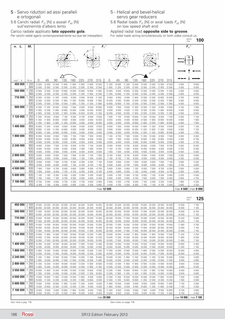
5 - Servo riduttori ad assi paralleli e ortogonali
5 - Helical and bevel-helical servo gear reducers
186 SR13 Edition February 2013
grand. size 100 n2 · Lh M2 Fr2
1) Fa21)
min-1 · h N m 0 45 90 135 180 225 270 315 0 45 90 135 180 225 270 315 450 000 1 250 12 500 12 500 12 500 11 800 11 800 11 800 11 800 12 500 11 200 10 600 11 200 12 500 12 500 12 500 12 500 12 500 4 500 9 000 900 12 500 12 500 12 500 12 500 12 500 12 500 12 500 12 500 11 800 11 200 12 500 12 500 12 500 12 500 12 500 12 500 4 500 9 000
560 000 1 250 12 500 12 500 12 500 10 600 10 000 10 600 10 600 11 800 10 000 9 500 10 600 12 500 12 500 12 500 12 500 11 200 4 500 9 000 900 12 500 12 500 12 500 12 500 12 500 11 200 11 800 12 500 11 200 10 600 11 200 12 500 12 500 12 500 12 500 12 500 4 500 9 000
710 000 1 250 12 500 12 500 11 200 9 500 9 000 9 500 10 000 11 200 9 000 8 500 9 500 11 800 12 500 12 500 10 600 10 000 3 750 8 500 900 12 500 12 500 12 500 11 800 11 200 10 600 10 600 11 800 10 000 9 500 10 600 12 500 12 500 12 500 12 500 11 800 4 500 8 500 630 12 500 12 500 12 500 12 500 11 800 11 200 11 200 11 800 10 600 10 600 11 200 12 500 12 500 12 500 12 500 11 800 4 500 9 000
900 000 1 250 12 500 11 200 10 000 8 000 7 500 8 000 9 000 10 600 8 500 7 500 8 500 11 200 12 500 11 200 9 500 8 500 3 150 7 500 900 11 800 12 500 11 800 10 600 10 000 9 500 10 000 10 600 9 000 9 000 9 500 11 200 12 500 12 500 11 800 10 600 4 500 8 000 630 11 800 12 500 12 500 11 800 10 600 10 000 10 000 11 200 10 000 9 500 10 000 11 800 12 500 12 500 12 500 11 200 4 500 8 500
1 120 000 1 250 11 200 10 000 8 000 7 100 6 300 6 700 8 500 9 500 7 500 7 100 8 000 10 600 11 200 10 000 8 500 7 100 2 500 7 100 900 11 200 11 800 10 600 9 500 9 000 9 000 9 000 10 000 8 500 8 000 9 000 10 600 12 500 11 800 10 600 10 000 4 000 7 500 630 11 200 11 800 11 800 11 200 10 000 9 500 9 500 10 000 9 000 9 000 9 500 10 600 11 800 12 500 11 800 10 600 4 500 7 500
1 400 000 900 10 600 11 200 9 500 8 500 8 000 8 000 8 500 9 500 8 000 7 500 8 000 10 000 11 800 11 200 9 500 9 000 3 550 7 100 630 10 600 11 200 11 200 10 600 9 500 9 000 9 000 9 500 8 500 8 000 8 500 10 000 11 200 11 800 11 200 9 500 4 500 7 100 450 10 600 11 200 10 600 10 000 9 500 9 000 9 000 9 500 9 000 8 500 9 000 10 000 11 200 11 200 10 600 10 000 4 500 7 500
1 800 000 900 10 000 10 000 8 500 7 500 7 100 7 500 7 500 8 500 7 100 6 700 7 500 9 000 11 200 10 000 8 500 7 500 3 000 6 300 630 10 000 10 600 10 000 9 500 8 500 8 000 8 000 9 000 7 500 7 500 8 000 9 500 10 600 11 200 10 600 9 000 4 250 6 700 450 9 500 10 000 10 000 9 500 9 000 8 500 8 500 9 000 8 000 8 000 8 500 9 500 10 000 10 600 10 000 9 000 4 500 6 700
2 240 000 900 9 500 9 000 7 500 6 700 6 000 6 700 7 100 8 000 6 300 6 000 6 700 8 500 10 000 9 000 7 500 6 700 2 500 6 000 630 9 000 10 000 9 000 8 500 8 000 7 500 7 500 8 000 7 100 6 700 7 500 8 500 10 000 10 600 9 500 8 500 3 750 6 300 450 9 000 9 500 9 500 9 000 8 000 8 000 8 000 8 500 7 500 7 500 8 000 9 000 9 500 10 000 9 500 8 500 4 500 6 300
2 800 000 630 8 500 9 500 8 500 7 500 7 500 6 700 7 100 7 500 6 700 6 300 6 700 8 000 9 500 9 500 8 500 7 500 3 350 5 600 450 8 500 9 000 9 000 8 500 7 500 7 100 7 500 8 000 7 100 6 700 7 100 8 000 9 000 9 500 9 000 8 000 4 250 6 000
3 550 000 630 8 000 8 500 7 500 6 700 6 300 6 300 6 300 7 100 6 000 5 600 6 300 7 500 9 000 8 500 7 500 7 100 3 000 5 300 450 8 000 8 500 8 500 8 000 7 100 6 700 6 700 7 100 6 300 6 300 6 700 7 500 8 500 9 000 8 500 7 500 3 750 5 600
4 500 000 630 7 500 7 500 6 700 6 000 5 600 5 600 6 000 6 700 5 600 5 300 5 600 7 100 8 500 7 500 6 700 6 300 2 500 5 000 450 7 500 8 000 8 000 7 100 6 700 6 300 6 300 6 700 6 000 5 600 6 300 7 100 8 000 8 500 8 000 6 700 3 350 5 000
5 600 000 630 7 100 7 100 6 300 5 300 5 000 5 300 5 300 6 000 5 000 4 750 5 300 6 700 8 000 7 100 6 300 5 600 2 240 4 500 450 7 100 7 500 7 100 6 700 6 300 5 600 5 600 6 300 5 600 5 300 5 600 6 700 7 500 8 000 7 500 6 300 3 000 4 750
7 100 000 630 6 700 6 300 5 600 4 750 4 250 4 750 5 000 5 600 4 500 4 250 4 750 6 000 7 100 6 300 5 300 5 000 1 900 4 250 450 6 300 7 100 6 300 6 000 5 600 5 300 5 300 5 600 5 000 4 750 5 300 6 300 7 100 7 100 6 700 6 000 2 650 4 250
max 12 500 max 4 500 max 9 000
Ved. note a pag. 176. See notes on page 176.
grand. size 125 450 000 2 500 19 000 20 000 20 000 20 000 20 000 20 000 19 000 18 000 20 000 20 000 20 000 20 000 19 000 20 000 20 000 20 000 14 000 7 100 1 800 20 000 20 000 20 000 20 000 20 000 20 000 20 000 19 000 20 000 20 000 20 000 20 000 20 000 20 000 20 000 20 000 14 000 7 100
560 000 2 500 17 000 19 000 20 000 20 000 20 000 20 000 18 000 16 000 20 000 20 000 18 000 18 000 17 000 18 000 20 000 20 000 14 000 6 700 1 800 19 000 20 000 20 000 20 000 20 000 20 000 19 000 18 000 20 000 20 000 19 000 19 000 20 000 20 000 20 000 20 000 14 000 7 100
710 000 2 500 15 000 16 000 18 000 20 000 20 000 20 000 16 000 14 000 20 000 19 000 17 000 16 000 15 000 16 000 19 000 20 000 13 200 5 600 1 800 17 000 20 000 20 000 20 000 20 000 20 000 18 000 16 000 20 000 19 000 18 000 18 000 19 000 20 000 20 000 20 000 13 200 7 100
900 000 2 500 14 000 14 000 16 000 19 000 20 000 19 000 15 000 13 200 20 000 17 000 15 000 14 000 12 500 14 000 16 000 19 000 11 800 4 750 1 800 16 000 18 000 20 000 20 000 20 000 19 000 16 000 15 000 20 000 18 000 16 000 16 000 17 000 18 000 20 000 20 000 12 500 7 100 1 250 17 000 19 000 20 000 20 000 20 000 19 000 17 000 16 000 20 000 18 000 17 000 17 000 18 000 20 000 20 000 20 000 12 500 7 100
1 120 000 2 500 12 500 11 800 14 000 17 000 19 000 18 000 13 200 11 800 19 000 16 000 14 000 11 800 10 600 11 800 15 000 17 000 11 200 3 750 1 800 14 000 17 000 18 000 20 000 20 000 18 000 15 000 13 200 19 000 17 000 15 000 15 000 15 000 16 000 18 000 20 000 11 800 6 300 1 250 15 000 17 000 20 000 20 000 20 000 18 000 16 000 15 000 19 000 17 000 16 000 16 000 17 000 19 000 20 000 20 000 11 800 7 100
1 400 000 1 800 13 200 15 000 16 000 18 000 20 000 17 000 14 000 12 500 18 000 15 000 14 000 14 000 14 000 14 000 16 000 18 000 10 600 5 300 1 250 14 000 16 000 19 000 20 000 19 000 17 000 15 000 14 000 18 000 16 000 15 000 15 000 16 000 17 000 19 000 19 000 11 200 7 100
1 800 000 1 800 11 800 13 200 14 000 16 000 18 000 15 000 12 500 11 200 17 000 14 000 12 500 12 500 11 800 12 500 14 000 16 000 10 000 4 500 1 250 13 200 15 000 17 000 19 000 18 000 16 000 13 200 12 500 16 000 15 000 14 000 13 200 14 000 16 000 17 000 18 000 10 000 6 300
2 240 000 1 800 11 200 11 800 12 500 15 000 17 000 14 000 11 200 10 000 16 000 13 200 11 800 11 200 10 000 11 200 13 200 15 000 9 500 4 000 1 250 11 800 14 000 16 000 17 000 17 000 14 000 12 500 11 800 15 000 14 000 12 500 12 500 13 200 14 000 15 000 17 000 9 500 5 600
2 800 000 1 250 11 200 13 200 14 000 16 000 16 000 13 200 11 800 10 600 14 000 12 500 11 800 11 800 12 500 13 200 14 000 16 000 9 000 5 000 900 11 800 13 200 15 000 16 000 15 000 14 000 11 800 11 200 14 000 13 200 12 500 12 500 13 200 14 000 15 000 15 000 9 000 6 300
3 550 000 1 250 10 000 11 800 13 200 14 000 15 000 12 500 10 600 9 500 13 200 11 800 10 600 10 600 11 200 11 800 12 500 14 000 8 000 4 500 900 11 200 12 500 14 000 15 000 14 000 12 500 11 200 10 600 13 200 11 800 11 200 11 200 11 800 13 200 14 000 14 000 8 500 5 600
4 500 000 1 250 9 500 10 600 11 800 13 200 14 000 11 800 9 500 9 000 12 500 11 200 10 000 10 000 10 000 10 000 11 800 13 200 7 500 4 000 900 10 000 11 200 13 200 14 000 13 200 11 800 10 600 9 500 12 500 11 200 10 600 10 600 11 200 12 500 13 200 13 200 7 500 5 000
5 600 000 1 250 8 500 9 500 10 600 11 800 13 200 11 200 9 000 8 000 11 800 10 000 9 000 9 000 8 500 9 000 10 600 11 800 7 100 3 350 900 9 500 10 600 12 500 13 200 12 500 11 200 9 500 9 000 11 800 10 600 9 500 9 500 10 600 11 200 11 800 12 500 7 100 4 500
7 100 000 1 250 8 000 8 500 9 000 10 600 11 800 10 000 8 000 7 500 11 200 9 500 8 500 8 000 7 500 8 000 9 500 10 600 6 700 2 800 900 8 500 10 000 11 200 12 500 11 800 10 000 9 000 8 000 10 600 9 500 9 000 9 000 9 500 10 000 11 200 11 800 6 700 4 000
max 20 000 max 14 000 max 7 100
UT.
C 9
15
Carico radiale applicato lato opposto gola. Applied radial load opposite side to groove.Per carichi radiali agenti contemporaneamente sui due lati interpellarci. For radial loads acting simultaneously on both sides consult us.
5
5.6 Carichi radiali Fr2 [N] o assiali Fa2 [N] sull’estre mi tà d’albero lento
5.6 Radial loads Fr2 [N] or axial loads Fa2 [N] on low speed shaft end
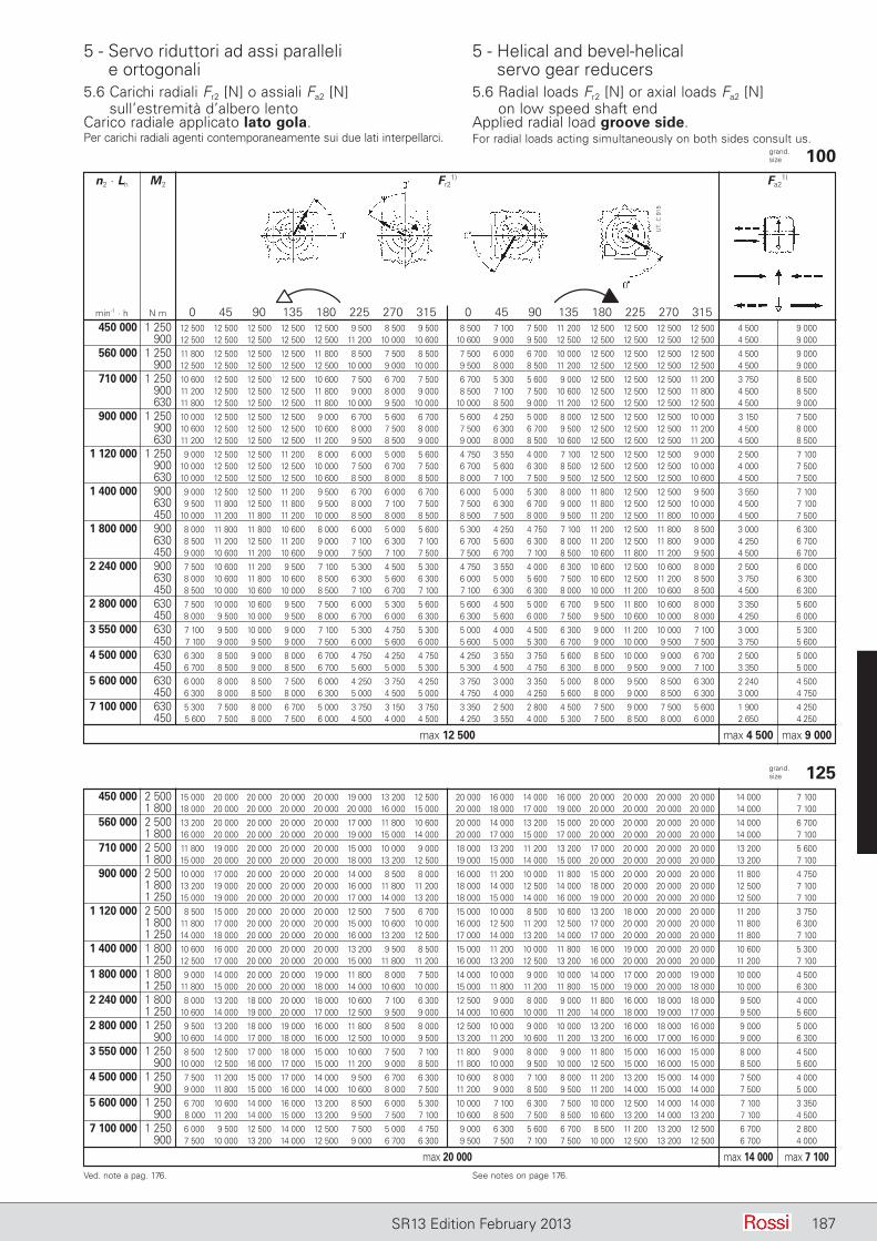
5 - Servo riduttori ad assi paralleli e ortogonali
5 - Helical and bevel-helical servo gear reducers
187SR13 Edition February 2013
grand. size 100 n2 · Lh M2 Fr2
1) Fa21)
min-1 · h N m 0 45 90 135 180 225 270 315 0 45 90 135 180 225 270 315 450 000 1 250 12 500 12 500 12 500 12 500 12 500 9 500 8 500 9 500 8 500 7 100 7 500 11 200 12 500 12 500 12 500 12 500 4 500 9 000 900 12 500 12 500 12 500 12 500 12 500 11 200 10 000 10 600 10 600 9 000 9 500 12 500 12 500 12 500 12 500 12 500 4 500 9 000
560 000 1 250 11 800 12 500 12 500 12 500 11 800 8 500 7 500 8 500 7 500 6 000 6 700 10 000 12 500 12 500 12 500 12 500 4 500 9 000 900 12 500 12 500 12 500 12 500 12 500 10 000 9 000 10 000 9 500 8 000 8 500 11 200 12 500 12 500 12 500 12 500 4 500 9 000
710 000 1 250 10 600 12 500 12 500 12 500 10 600 7 500 6 700 7 500 6 700 5 300 5 600 9 000 12 500 12 500 12 500 11 200 3 750 8 500 900 11 200 12 500 12 500 12 500 11 800 9 000 8 000 9 000 8 500 7 100 7 500 10 600 12 500 12 500 12 500 11 800 4 500 8 500 630 11 800 12 500 12 500 12 500 11 800 10 000 9 500 10 000 10 000 8 500 9 000 11 200 12 500 12 500 12 500 12 500 4 500 9 000
900 000 1 250 10 000 12 500 12 500 12 500 9 000 6 700 5 600 6 700 5 600 4 250 5 000 8 000 12 500 12 500 12 500 10 000 3 150 7 500 900 10 600 12 500 12 500 12 500 10 600 8 000 7 500 8 000 7 500 6 300 6 700 9 500 12 500 12 500 12 500 11 200 4 500 8 000 630 11 200 12 500 12 500 12 500 11 200 9 500 8 500 9 000 9 000 8 000 8 500 10 600 12 500 12 500 12 500 11 200 4 500 8 500
1 120 000 1 250 9 000 12 500 12 500 11 200 8 000 6 000 5 000 5 600 4 750 3 550 4 000 7 100 12 500 12 500 12 500 9 000 2 500 7 100 900 10 000 12 500 12 500 12 500 10 000 7 500 6 700 7 500 6 700 5 600 6 300 8 500 12 500 12 500 12 500 10 000 4 000 7 500 630 10 000 12 500 12 500 12 500 10 600 8 500 8 000 8 500 8 000 7 100 7 500 9 500 12 500 12 500 12 500 10 600 4 500 7 500
1 400 000 900 9 000 12 500 12 500 11 200 9 500 6 700 6 000 6 700 6 000 5 000 5 300 8 000 11 800 12 500 12 500 9 500 3 550 7 100 630 9 500 11 800 12 500 11 800 9 500 8 000 7 100 7 500 7 500 6 300 6 700 9 000 11 800 12 500 12 500 10 000 4 500 7 100 450 10 000 11 200 11 800 11 200 10 000 8 500 8 000 8 500 8 500 7 500 8 000 9 500 11 200 12 500 11 800 10 000 4 500 7 500
1 800 000 900 8 000 11 800 11 800 10 600 8 000 6 000 5 000 5 600 5 300 4 250 4 750 7 100 11 200 12 500 11 800 8 500 3 000 6 300 630 8 500 11 200 12 500 11 200 9 000 7 100 6 300 7 100 6 700 5 600 6 300 8 000 11 200 12 500 11 800 9 000 4 250 6 700 450 9 000 10 600 11 200 10 600 9 000 7 500 7 100 7 500 7 500 6 700 7 100 8 500 10 600 11 800 11 200 9 500 4 500 6 700
2 240 000 900 7 500 10 600 11 200 9 500 7 100 5 300 4 500 5 300 4 750 3 550 4 000 6 300 10 600 12 500 10 600 8 000 2 500 6 000 630 8 000 10 600 11 800 10 600 8 500 6 300 5 600 6 300 6 000 5 000 5 600 7 500 10 600 12 500 11 200 8 500 3 750 6 300 450 8 500 10 000 10 600 10 000 8 500 7 100 6 700 7 100 7 100 6 300 6 300 8 000 10 000 11 200 10 600 8 500 4 500 6 300
2 800 000 630 7 500 10 000 10 600 9 500 7 500 6 000 5 300 5 600 5 600 4 500 5 000 6 700 9 500 11 800 10 600 8 000 3 350 5 600 450 8 000 9 500 10 000 9 500 8 000 6 700 6 000 6 300 6 300 5 600 6 000 7 500 9 500 10 600 10 000 8 000 4 250 6 000
3 550 000 630 7 100 9 500 10 000 9 000 7 100 5 300 4 750 5 300 5 000 4 000 4 500 6 300 9 000 11 200 10 000 7 100 3 000 5 300 450 7 100 9 000 9 500 9 000 7 500 6 000 5 600 6 000 5 600 5 000 5 300 6 700 9 000 10 000 9 500 7 500 3 750 5 600
4 500 000 630 6 300 8 500 9 000 8 000 6 700 4 750 4 250 4 750 4 250 3 550 3 750 5 600 8 500 10 000 9 000 6 700 2 500 5 000 450 6 700 8 500 9 000 8 500 6 700 5 600 5 000 5 300 5 300 4 500 4 750 6 300 8 000 9 500 9 000 7 100 3 350 5 000
5 600 000 630 6 000 8 000 8 500 7 500 6 000 4 250 3 750 4 250 3 750 3 000 3 350 5 000 8 000 9 500 8 500 6 300 2 240 4 500 450 6 300 8 000 8 500 8 000 6 300 5 000 4 500 5 000 4 750 4 000 4 250 5 600 8 000 9 000 8 500 6 300 3 000 4 750
7 100 000 630 5 300 7 500 8 000 6 700 5 000 3 750 3 150 3 750 3 350 2 500 2 800 4 500 7 500 9 000 7 500 5 600 1 900 4 250 450 5 600 7 500 8 000 7 500 6 000 4 500 4 000 4 500 4 250 3 550 4 000 5 300 7 500 8 500 8 000 6 000 2 650 4 250
max 12 500 max 4 500 max 9 000
Ved. note a pag. 176. See notes on page 176.
grand. size 125 450 000 2 500 15 000 20 000 20 000 20 000 20 000 19 000 13 200 12 500 20 000 16 000 14 000 16 000 20 000 20 000 20 000 20 000 14 000 7 100 1 800 18 000 20 000 20 000 20 000 20 000 20 000 16 000 15 000 20 000 18 000 17 000 19 000 20 000 20 000 20 000 20 000 14 000 7 100
560 000 2 500 13 200 20 000 20 000 20 000 20 000 17 000 11 800 10 600 20 000 14 000 13 200 15 000 20 000 20 000 20 000 20 000 14 000 6 700 1 800 16 000 20 000 20 000 20 000 20 000 19 000 15 000 14 000 20 000 17 000 15 000 17 000 20 000 20 000 20 000 20 000 14 000 7 100
710 000 2 500 11 800 19 000 20 000 20 000 20 000 15 000 10 000 9 000 18 000 13 200 11 200 13 200 17 000 20 000 20 000 20 000 13 200 5 600 1 800 15 000 20 000 20 000 20 000 20 000 18 000 13 200 12 500 19 000 15 000 14 000 15 000 20 000 20 000 20 000 20 000 13 200 7 100
900 000 2 500 10 000 17 000 20 000 20 000 20 000 14 000 8 500 8 000 16 000 11 200 10 000 11 800 15 000 20 000 20 000 20 000 11 800 4 750 1 800 13 200 19 000 20 000 20 000 20 000 16 000 11 800 11 200 18 000 14 000 12 500 14 000 18 000 20 000 20 000 20 000 12 500 7 100 1 250 15 000 19 000 20 000 20 000 20 000 17 000 14 000 13 200 18 000 15 000 14 000 16 000 19 000 20 000 20 000 20 000 12 500 7 100
1 120 000 2 500 8 500 15 000 20 000 20 000 20 000 12 500 7 500 6 700 15 000 10 000 8 500 10 600 13 200 18 000 20 000 20 000 11 200 3 750 1 800 11 800 17 000 20 000 20 000 20 000 15 000 10 600 10 000 16 000 12 500 11 200 12 500 17 000 20 000 20 000 20 000 11 800 6 300 1 250 14 000 18 000 20 000 20 000 20 000 16 000 13 200 12 500 17 000 14 000 13 200 14 000 17 000 20 000 20 000 20 000 11 800 7 100
1 400 000 1 800 10 600 16 000 20 000 20 000 20 000 13 200 9 500 8 500 15 000 11 200 10 000 11 800 16 000 19 000 20 000 20 000 10 600 5 300 1 250 12 500 17 000 20 000 20 000 20 000 15 000 11 800 11 200 16 000 13 200 12 500 13 200 16 000 20 000 20 000 20 000 11 200 7 100
1 800 000 1 800 9 000 14 000 20 000 20 000 19 000 11 800 8 000 7 500 14 000 10 000 9 000 10 000 14 000 17 000 20 000 19 000 10 000 4 500 1 250 11 800 15 000 20 000 20 000 18 000 14 000 10 600 10 000 15 000 11 800 11 200 11 800 15 000 19 000 20 000 18 000 10 000 6 300
2 240 000 1 800 8 000 13 200 18 000 20 000 18 000 10 600 7 100 6 300 12 500 9 000 8 000 9 000 11 800 16 000 18 000 18 000 9 500 4 000 1 250 10 600 14 000 19 000 20 000 17 000 12 500 9 500 9 000 14 000 10 600 10 000 11 200 14 000 18 000 19 000 17 000 9 500 5 600
2 800 000 1 250 9 500 13 200 18 000 19 000 16 000 11 800 8 500 8 000 12 500 10 000 9 000 10 000 13 200 16 000 18 000 16 000 9 000 5 000 900 10 600 14 000 17 000 18 000 16 000 12 500 10 000 9 500 13 200 11 200 10 600 11 200 13 200 16 000 17 000 16 000 9 000 6 300
3 550 000 1 250 8 500 12 500 17 000 18 000 15 000 10 600 7 500 7 100 11 800 9 000 8 000 9 000 11 800 15 000 16 000 15 000 8 000 4 500 900 10 000 12 500 16 000 17 000 15 000 11 200 9 000 8 500 11 800 10 000 9 500 10 000 12 500 15 000 16 000 15 000 8 500 5 600
4 500 000 1 250 7 500 11 200 15 000 17 000 14 000 9 500 6 700 6 300 10 600 8 000 7 100 8 000 11 200 13 200 15 000 14 000 7 500 4 000 900 9 000 11 800 15 000 16 000 14 000 10 600 8 000 7 500 11 200 9 000 8 500 9 500 11 200 14 000 15 000 14 000 7 500 5 000
5 600 000 1 250 6 700 10 600 14 000 16 000 13 200 8 500 6 000 5 300 10 000 7 100 6 300 7 500 10 000 12 500 14 000 14 000 7 100 3 350 900 8 000 11 200 14 000 15 000 13 200 9 500 7 500 7 100 10 600 8 500 7 500 8 500 10 600 13 200 14 000 13 200 7 100 4 500
7 100 000 1 250 6 000 9 500 12 500 14 000 12 500 7 500 5 000 4 750 9 000 6 300 5 600 6 700 8 500 11 200 13 200 12 500 6 700 2 800 900 7 500 10 000 13 200 14 000 12 500 9 000 6 700 6 300 9 500 7 500 7 100 7 500 10 000 12 500 13 200 12 500 6 700 4 000
max 20 000 max 14 000 max 7 100
UT.
C 9
15
Carico radiale applicato lato gola. Applied radial load groove side.Per carichi radiali agenti contemporaneamente sui due lati interpellarci. For radial loads acting simultaneously on both sides consult us.
5.6 Carichi radiali Fr2 [N] o assiali Fa2 [N] sull’estre mi tà d’albero lento
5.6 Radial loads Fr2 [N] or axial loads Fa2 [N] on low speed shaft end
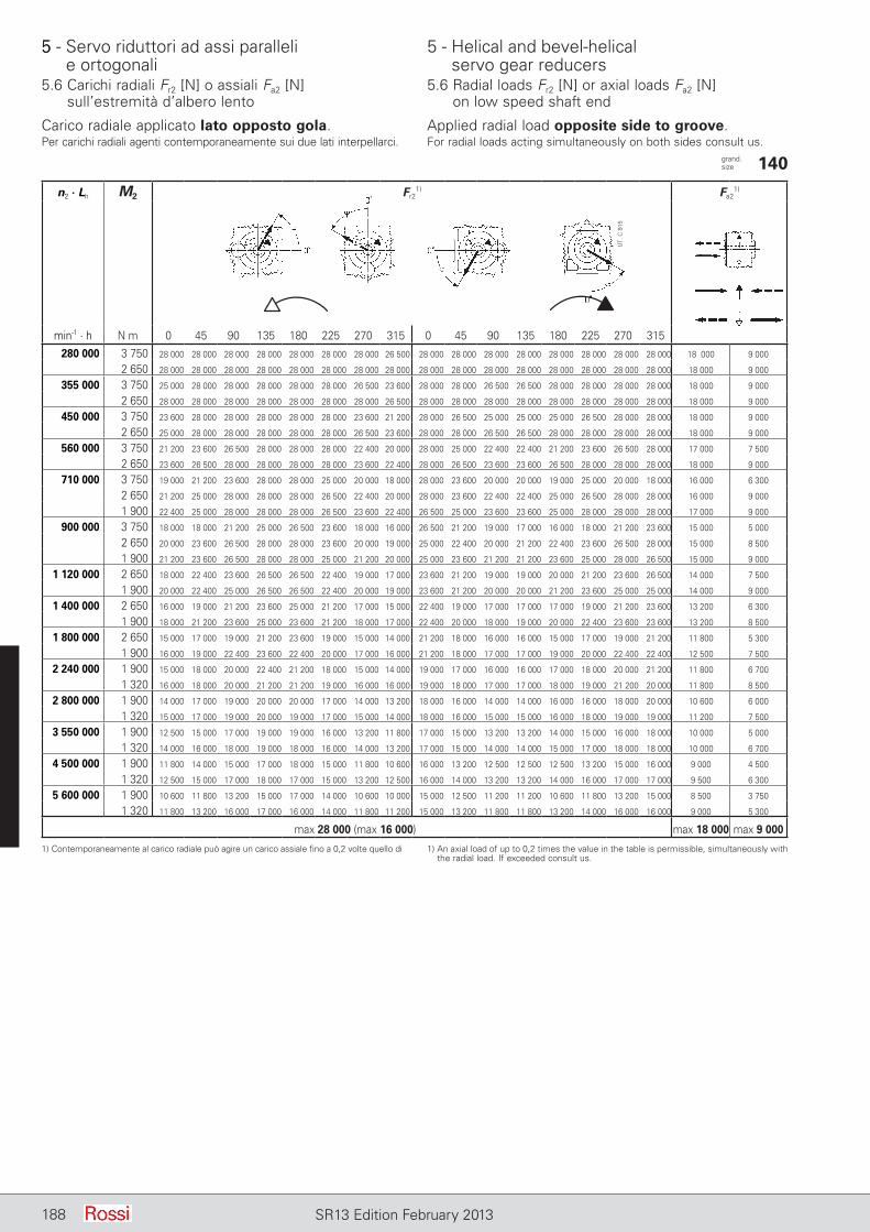
5 - Servo riduttori ad assi paralleli e ortogonali
5 - Helical and bevel-helical servo gear reducers
188 SR13 Edition February 2013
Carico radiale applicato lato opposto gola. Applied radial load opposite side to groove.Per carichi radiali agenti contemporaneamente sui due lati interpellarci. For radial loads acting simultaneously on both sides consult us.
n2 ∙ Lh M2 Fr21) Fa2
1)
min-1 ∙ h N m 0 45 90 135 180 225 270 315 0 45 90 135 180 225 270 315280 000 3 750 28 000 28 000 28 000 28 000 28 000 28 000 28 000 26 500 28 000 28 000 28 000 28 000 28 000 28 000 28 000 28 000 18 000 9 000
2 650 28 000 28 000 28 000 28 000 28 000 28 000 28 000 28 000 28 000 28 000 28 000 28 000 28 000 28 000 28 000 28 000 18 000 9 000
355 000 3 750 25 000 28 000 28 000 28 000 28 000 28 000 26 500 23 600 28 000 28 000 26 500 26 500 28 000 28 000 28 000 28 000 18 000 9 000
2 650 28 000 28 000 28 000 28 000 28 000 28 000 28 000 26 500 28 000 28 000 28 000 28 000 28 000 28 000 28 000 28 000 18 000 9 000
450 000 3 750 23 600 28 000 28 000 28 000 28 000 28 000 23 600 21 200 28 000 26 500 25 000 25 000 25 000 26 500 28 000 28 000 18 000 9 000
2 650 25 000 28 000 28 000 28 000 28 000 28 000 26 500 23 600 28 000 28 000 26 500 26 500 28 000 28 000 28 000 28 000 18 000 9 000
560 000 3 750 21 200 23 600 26 500 28 000 28 000 28 000 22 400 20 000 28 000 25 000 22 400 22 400 21 200 23 600 26 500 28 000 17 000 7 500
2 650 23 600 26 500 28 000 28 000 28 000 28 000 23 600 22 400 28 000 26 500 23 600 23 600 26 500 28 000 28 000 28 000 18 000 9 000
710 000 3 750 19 000 21 200 23 600 28 000 28 000 25 000 20 000 18 000 28 000 23 600 20 000 20 000 19 000 25 000 20 000 18 000 16 000 6 300
2 650 21 200 25 000 28 000 28 000 28 000 26 500 22 400 20 000 28 000 23 600 22 400 22 400 25 000 26 500 28 000 28 000 16 000 9 000
1 900 22 400 25 000 28 000 28 000 28 000 26 500 23 600 22 400 26 500 25 000 23 600 23 600 25 000 28 000 28 000 28 000 17 000 9 000
900 000 3 750 18 000 18 000 21 200 25 000 26 500 23 600 18 000 16 000 26 500 21 200 19 000 17 000 16 000 18 000 21 200 23 600 15 000 5 000
2 650 20 000 23 600 26 500 28 000 28 000 23 600 20 000 19 000 25 000 22 400 20 000 21 200 22 400 23 600 26 500 28 000 15 000 8 500
1 900 21 200 23 600 26 500 28 000 28 000 25 000 21 200 20 000 25 000 23 600 21 200 21 200 23 600 25 000 28 000 26 500 15 000 9 000
1 120 000 2 650 18 000 22 400 23 600 26 500 26 500 22 400 19 000 17 000 23 600 21 200 19 000 19 000 20 000 21 200 23 600 26 500 14 000 7 500
1 900 20 000 22 400 25 000 26 500 26 500 22 400 20 000 19 000 23 600 21 200 20 000 20 000 21 200 23 600 25 000 25 000 14 000 9 000
1 400 000 2 650 16 000 19 000 21 200 23 600 25 000 21 200 17 000 15 000 22 400 19 000 17 000 17 000 17 000 19 000 21 200 23 600 13 200 6 300
1 900 18 000 21 200 23 600 25 000 23 600 21 200 18 000 17 000 22 400 20 000 18 000 19 000 20 000 22 400 23 600 23 600 13 200 8 500
1 800 000 2 650 15 000 17 000 19 000 21 200 23 600 19 000 15 000 14 000 21 200 18 000 16 000 16 000 15 000 17 000 19 000 21 200 11 800 5 300
1 900 16 000 19 000 22 400 23 600 22 400 20 000 17 000 16 000 21 200 18 000 17 000 17 000 19 000 20 000 22 400 22 400 12 500 7 500
2 240 000 1 900 15 000 18 000 20 000 22 400 21 200 18 000 15 000 14 000 19 000 17 000 16 000 16 000 17 000 18 000 20 000 21 200 11 800 6 700
1 320 16 000 18 000 20 000 21 200 21 200 19 000 16 000 16 000 19 000 18 000 17 000 17 000 18 000 19 000 21 200 20 000 11 800 8 500
2 800 000 1 900 14 000 17 000 19 000 20 000 20 000 17 000 14 000 13 200 18 000 16 000 14 000 14 000 16 000 16 000 18 000 20 000 10 600 6 000
1 320 15 000 17 000 19 000 20 000 19 000 17 000 15 000 14 000 18 000 16 000 15 000 15 000 16 000 18 000 19 000 19 000 11 200 7 500
3 550 000 1 900 12 500 15 000 17 000 19 000 19 000 16 000 13 200 11 800 17 000 15 000 13 200 13 200 14 000 15 000 16 000 18 000 10 000 5 000
1 320 14 000 16 000 18 000 19 000 18 000 16 000 14 000 13 200 17 000 15 000 14 000 14 000 15 000 17 000 18 000 18 000 10 000 6 700
4 500 000 1 900 11 800 14 000 15 000 17 000 18 000 15 000 11 800 10 600 16 000 13 200 12 500 12 500 12 500 13 200 15 000 16 000 9 000 4 500
1 320 12 500 15 000 17 000 18 000 17 000 15 000 13 200 12 500 16 000 14 000 13 200 13 200 14 000 16 000 17 000 17 000 9 500 6 300
5 600 000 1 900 10 600 11 800 13 200 15 000 17 000 14 000 10 600 10 000 15 000 12 500 11 200 11 200 10 600 11 800 13 200 15 000 8 500 3 750
1 320 11 800 13 200 16 000 17 000 16 000 14 000 11 800 11 200 15 000 13 200 11 800 11 800 13 200 14 000 16 000 16 000 9 000 5 300
max 28 000 (max 16 000) max 18 000 max 9 000
grand. size 140
UT.
C 9
15
5
5.6 Carichi radiali Fr2 [N] o assiali Fa2 [N] sull’estre mi tà d’albero lento
5.6 Radial loads Fr2 [N] or axial loads Fa2 [N] on low speed shaft end
1) Contemporaneamente al carico radiale può agire un carico assiale fino a 0,2 volte quello di 1) An axial load of up to 0,2 times the value in the table is permissible, simultaneously with the radial load. If exceeded consult us.

5 - Servo riduttori ad assi paralleli e ortogonali
5 - Helical and bevel-helical servo gear reducers
189SR13 Edition February 2013
Carico radiale applicato lato gola. Applied radial load groove side.Per carichi radiali agenti contemporaneamente sui due lati interpellarci. For radial loads acting simultaneously on both sides consult us. grand. size 140
n2 ∙ Lh M2 Fr21) Fa2
1)
min-1 ∙ h N m 0 45 90 135 180 225 270 315 0 45 90 135 180 225 270 315280 000 3 750 23 600 28 000 28 000 28 000 28 000 28 000 22 400 20 000 28 000 25 000 22 400 25 000 28 000 28 000 28 000 28 000 18 000 9 000
2 650 28 000 28 000 28 000 28 000 28 000 28 000 25 000 25 000 28 000 28 000 26 500 28 000 28 000 28 000 28 000 28 000 18 000 9 000
355 000 3 750 21 200 28 000 28 000 28 000 28 000 26 500 19 000 18 000 28 000 22 400 20 000 23 600 28 000 28 000 28 000 28 000 18 000 9 000
2 650 25 000 28 000 28 000 28 000 28 000 28 000 23 600 22 400 28 000 26 500 23 600 26 500 28 000 28 000 28 000 28 000 18 000 9 000
450 000 3 750 19 000 28 000 28 000 28 000 28 000 25 000 17 000 16 000 28 000 21 200 19 000 21 200 28 000 28 000 28 000 28 000 18 000 9 000
2 650 23 600 28 000 28 000 28 000 28 000 26 500 21 200 20 000 28 000 23 600 22 400 23 600 28 000 28 000 28 000 28 000 18 000 9 000
560 000 3 750 17 000 26 500 28 000 28 000 28 000 22 400 15 000 14 000 25 000 19 000 16 000 19 000 25 000 28 000 28 000 28 000 17 000 7 500
2 650 21 200 28 000 28 000 28 000 28 000 25 000 19 000 18 000 26 500 20 000 20 000 21 200 26 500 28 000 28 000 28 000 18 000 9 000
710 000 3 750 15 000 23 600 28 000 28 000 28 000 20 000 13 200 11 800 23 600 16 000 14 000 17 000 21 200 28 000 28 000 28 000 16 000 6 300
2 650 19 000 25 000 28 000 28 000 28 000 22 400 17 000 16 000 25 000 20 000 18 000 20 000 25 000 28 000 28 000 28 000 16 000 9 000
1 900 21 200 26 500 28 000 28 000 28 000 23 600 20 000 19 000 25 000 21 200 20 000 21 200 25 000 28 000 28 000 28 000 17 000 9 000
900 000 3 750 13 200 21 200 28 000 28 000 28 000 18 000 11 200 10 000 21 200 15 000 13 200 15 000 19 000 25 000 28 000 28 000 15 000 5 000
2 650 17 000 23 600 28 000 28 000 28 000 21 200 15 000 14 000 22 400 18 000 16 000 18 000 23 600 28 000 28 000 28 000 15 000 8 500
1 900 19 000 25 000 28 000 28 000 28 000 22 400 18 000 17 000 23 600 20 000 19 000 20 000 23 600 28 000 28 000 28 000 15 000 9 000
1 120 000 2 650 15 000 22 400 28 000 28 000 28 000 19 000 14 000 12 500 21 200 16 000 15 000 16 000 21 200 26 500 28 000 28 000 14 000 7 500
1 900 18 000 22 400 28 000 28 000 26 500 21 200 17 000 16 000 22 400 18 000 17 000 18 000 22 400 26 500 28 000 26 500 14 000 9 000
1 400 000 2 650 13 200 20 000 26 500 28 000 25 000 17 000 12 500 11 200 19 000 14 000 13 200 15 000 20 000 23 600 26 500 26 500 13 200 6 300
1 900 16 000 21 200 26 500 28 000 25 000 19 000 15 000 14 000 20 000 17 000 15 000 17 000 20 000 25 000 26 500 25 000 13 200 8 500
1 800 000 2 650 11 800 19 000 25 000 28 000 23 600 16 000 10 600 10 000 18 000 13 200 11 800 13 200 17 000 21 200 25 000 25 000 11 800 5 300
1 900 15 000 20 000 25 000 26 500 23 600 17 000 13 200 12 500 19 000 15 000 14 000 15 000 19 000 23 600 26 500 23 600 12 500 7 500
2 240 000 1 900 13 200 18 000 23 600 26 500 22 400 16 000 12 500 11 200 18 000 14 000 12 500 14 000 18 000 22 400 23 600 22 400 11 800 6 700
1 320 15 000 19 000 22 400 23 600 21 200 17 000 14 000 13 200 18 000 15 000 14 000 15 000 18 000 21 200 22 400 21 200 11 800 8 500
2 800 000 1 900 11 800 17 000 22 400 25 000 21 200 15 000 10 600 10 000 16 000 12 500 11 200 13 000 16 000 20 000 22 400 21 200 10 600 6 000
1 320 14 000 17 000 21 200 22 400 20 000 16 000 13 200 12 500 17 000 14 000 13 200 14 000 17 000 20 000 21 200 20 000 11 200 7 500
3 550 000 1 900 10 600 15 000 21 200 23 600 19 000 13 200 9 500 9 000 15 000 11 200 10 000 11 800 15 000 18 000 21 200 20 000 10 000 5 000
1 320 12 500 16 000 20 000 21 200 19 000 14 000 11 800 11 200 15 000 13 200 11 800 13 200 15 000 19 000 20 000 19 000 10 000 6 700
4 500 000 1 900 9 500 14 000 19 000 21 200 18 000 12 500 8 500 8 000 14 000 10 000 9 000 10 600 14 000 17 000 19 000 19 000 9 000 4 500
1 320 11 800 15 000 19 000 20 000 18 000 13 200 10 600 10 000 14 000 11 800 11 200 11 800 15 000 18 000 19 000 18 000 9 500 6 300
5 600 000 1 900 8 500 13 200 17 000 20 000 17 000 11 200 7 500 6 700 12 500 9 000 8 000 9 500 12 500 15 000 18 000 17 000 8 500 3 750
1 320 10 000 14 000 18 000 19 000 16 000 12 500 9 500 9 000 13 200 10 600 10 000 11 200 13 200 17 000 18 000 17 000 9 000 5 300
max 28 000 (max 16 000) max 18 000 max 9 000
UT.
C 9
15
5.6 Carichi radiali Fr2 [N] o assiali Fa2 [N] sull’estre mi tà d’albero lento
5.6 Radial loads Fr2 [N] or axial loads Fa2 [N] on low speed shaft end
1) Contemporaneamente al carico radiale può agire un carico assiale fino a 0,2 volte quello di tabella e viceversa. Per valori superiori interpellarci.
1) An axial load of up to 0,2 times the value in the table is permissible, simultaneously with the radial load. If exceeded consult us.
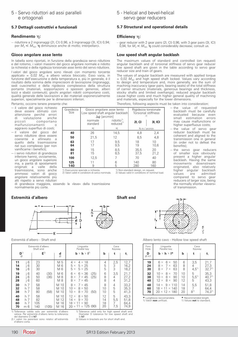
5 - Servo riduttori ad assi paralleli e ortogonali
5 - Helical and bevel-helical servo gear reducers
190 SR13 Edition February 2013
Estremità d’albero Shaft end
Estremità d’albero - Shaft end Albero lento cavo - Hollow low speed shaft
Estremità d’albero Linguetta Cava Shaft end Parallel key Keyway
D1) E2) d b 3 h 3 l2) b t t1 Ø Ø
11 j 6 23 M 5 4 3 4 3 18 4 2,5 12,7 14 j 6 30 M 6 5 3 5 3 25 5 3 16,2 16 j 6 30 M 6 5 3 5 3 25 5 3 18,2 19 j 6 40 (30) M 6 6 3 6 3 36 (25) 6 3,5 21,7 24 j 6 50 (36) M 8 8 3 7 3 45 (25) 8 4 27,2 28 j 6 60 M 8 8 3 7 3 45 8 4 31,2 30 h 7 58 M 10 8 3 7 3 45 8 4 33,2 32 h 7 58 M 10 10 3 8 3 50 10 5 35,3 38 h 7 80 (58) M 10 10 3 8 3 70 (50) 10 5 41,3 40 h 7 58 M 10 12 3 8 3 50 12 5 43,3 48 h 7 82 M 12 14 3 9 3 70 14 5,5 51,8 60 h 7 105 M 16 18 3 11 3 90 18 7 64,4 70 m 6 140 (105) M 16 20 3 11 3 125 (90) 20 7,5 74,9
Foro Linguetta Cava Hole Parallel key Keyway
D b 3 h 3 l* b t t1 Ø H7
19 6 3 6 3 50 6 3,5 21,7 24 8 3 7 3 63 8 4 27,3 30 8 3 7 3 63 8 4,51) 32,71)
32 10 3 8 3 70 10 5 35,3 38 10 3 8 3 90 10 5,51) 40,71)
40 12 3 8 3 90 12 5,51) 43,3 48 14 3 9 3 110 14 5,5 51,8 60 18 3 11 3 140 18 7 64,4 70 20 3 12 3 180 20 81) 74,31)
1) Tolleranza valida solo per estremità d’albero veloce. Per estremità d’albero lento la tolleranza del diametro D è h7.
2) I valori tra parentesi sono relativi all’estremità d’albero corta.
1) Tolerance valid only for high speed shaft end. Diameter D tolerance for low speed shaft end is h7.
2) Values in brackets are for short shaft end.
* Lunghezza raccomandata.1) Valori non unificati.
* Recommended length.1) Values not to standard.
Gioco angolare asse lentoIn tabella sono riportati, in funzione della grandezza servo riduttore e del rotismo, i valori massimi del gioco angolare normale e ridotto (a richiesta) e della rigidezza torsionale asse lento del servo riduttore.I valori del gioco angolare sono rilevati con momento torcente applicato ≈ 0,02 MN2 e albero veloce bloccato. Esso varia, in funzione dell’esecuzione e della temperatura e, più in generale, è il risultato della somma delle imprecisioni di lavorazione (ingranaggi, sedi cuscinetto) e della rigidezza complessiva della struttura portante (materiali, sopportazioni e spessori generosi, alberi tozzi e sbalzi contenuti); giochi angolari ridotti comportano costi, qualità generale delle lavorazioni e dei materiali esponenzialmente superiori, specialmente per le dimensioni inferiori.Pertanto, occorre tenere presente che:– il valore del gioco richiesto
deve es sere stimato con at tenzione perché errori di va lutazione anche piccoli comportano malfunzionamenti o ag gravio superfluo di costi;
– il valore del gioco del servo riduttore deve essere coerente e al lineato a quello della trasmissione nel suo complesso (per non vanificarne i benefici);
– i servo riduttori di grandezza inferiore han no, ovviamente, un gioco angolare superiore ma, a parità di spostamenti originati a valle della trasmissione, sono anche ammessi valori di gioco angolare relativamente più alti rispetto a servo riduttori di grandezza maggiore, essendo le «leve» della trasmissione normalmente più corte.
Low speed shaft angular bac k lashThe maximum values of standard and controlled (on request) angular backlash and of torsional stiffness of servo gear reducer low speed shaft are given in the table according to servo gear reducer size and train of gears.The values of angular backlash are measured with applied torque ≈ 0,02 MN2 and high speed shaft locked. Values vary according to design and temperature and, more generally, are the sum of machinig inaccuracy (gear pairs, bearing seats) of the total stiffness of carrier structure (materials, generous bearings and thickness, stocky shafts and limited overhangs); reduced angular backlash cause higher costs and much higher general quality of machining and materials, especially for the lower dimensions.Therefore, following aspects must be taken into consideration:
– the value of requested backlash must be carefully evaluated because even small estimation errors may cause malfunctions or higher superfluous costs;
– the value of servo gear reducer backlash must be coherent and aligned to the transmission one in general (in order not to defeat the benefits);
– the servo gear reducers of smaller size obviously present a higher angular backlash. Having the same movements downstream originated, also relatively higher angular backlash values are admitted compared to servo gear reducers of larger size, being the normally shorter «levers» of transmission.
Grandezza Gioco angolare asse lento Rigidezza torsionale Size Low speed shaft angular backlash Torsional stiffness D [arcmin] 2)
normale ridotto1) 2I, CI 3I, ICI standard reduced1)
N m / arcmin
40 26 14,5 4,8 2,4 50 21,5 12 8,5 4,8 63 17 9,5 18 10 64 17 9,5 19 10,6 80 15 8,5 35,5 20 81 15 8,5 37,5 21,2 100 12,5 7 70 40 125 11 6 140 80 140 9 5 280 1601) Esecuzione speciale a richiesta.2) Valori validi in condizioni di carico nominale.
1) Non-standard design, on request.2) Values valid in conditions of nominal load.
Rendimento h:– riduttore a 2 ingranaggi (2I, CI) 0,96, a 3 ingranaggi (3I, ICI) 0,94;
per M2 ,, MN2, h diminuisce anche di molto; interpellarci.
Efficiency h:– gear reducer with 2 gear pairs (2I, CI) 0,96, with 3 gear pairs (3I, ICI)
0,94; for M2 ,, MN2, h could considerably decrease; consult us.
5.7 Dettagli costruttivi e funzionali 5.7 Structural and operational details
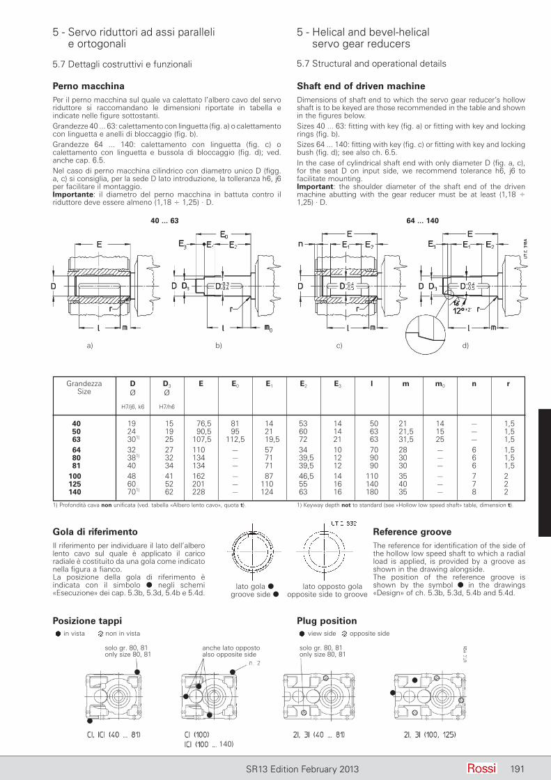
5 - Servo riduttori ad assi paralleli e ortogonali
5 - Helical and bevel-helical servo gear reducers
191SR13 Edition February 2013
5.7 Dettagli costruttivi e funzionali 5.7 Structural and operational details
Perno macchinaPer il perno macchina sul quale va calettato l’albero cavo del servo riduttore si raccomandano le dimensioni riportate in tabella e indicate nelle figure sottostanti.Grandezze 40 ... 63: calettamento con linguetta (fig. a) o calettamento con linguetta e anelli di bloccaggio (fig. b).Grandezze 64 ... 140: calettamento con linguetta (fig. c) o calettamento con linguetta e bussola di bloccaggio (fig. d); ved. anche cap. 6.5.Nel caso di perno macchina cilindrico con diametro unico D (figg. a, c) si consiglia, per la sede D lato introduzione, la tolleranza h6, j6 per facilitare il montaggio.Importante: il diametro del perno macchina in battuta contro il riduttore deve essere almeno (1,18 4 1,25) · D.
Shaft end of driven machineDimensions of shaft end to which the servo gear reducer’s hollow shaft is to be keyed are those recommended in the table and shown in the figures below.Sizes 40 ... 63: fitting with key (fig. a) or fitting with key and locking rings (fig. b).Sizes 64 ... 140: fitting with key (fig. c) or fitting with key and locking bush (fig. d); see also ch. 6.5.In the case of cylindrical shaft end with only diameter D (fig. a, c), for the seat D on input side, we recommend tolerance h6, j6 to facilitate mounting.Important: the shoulder diameter of the shaft end of the driven ma chine abutting with the gear reducer must be at least (1,18 4 1,25) · D.
40 ... 63 64 ... 140
Grandezza D D3 E E0 E1 E2 E3 l m m0 n r Size Ø Ø
H7/j6, k6 H7/h6
40 19 15 76,5 81 14 53 14 50 21 14 – 1,5 50 24 19 90,5 95 21 60 14 63 21,5 15 – 1,5 63 301) 25 107,5 112,5 19,5 72 21 63 31,5 25 – 1,5 64 32 27 110 – 57 34 10 70 28 – 6 1,5 80 381) 32 134 – 71 39,5 12 90 30 – 6 1,5 81 40 34 134 – 71 39,5 12 90 30 – 6 1,5 100 48 41 162 – 87 46,5 14 110 35 – 7 2 125 60 52 201 – 110 55 16 140 40 – 7 2 140 701) 62 228 – 124 63 16 180 35 – 8 2
1) Profondità cava non unificata (ved. tabella «Albero lento cavo», quota t). 1) Keyway depth not to standard (see «Hollow low speed shaft» table, dimension t).
Gola di riferimentoIl riferimento per individuare il lato dell’albero lento cavo sul quale è applicato il carico radia le è costituito da una gola come indicato nella figura a fianco.La posizione della gola di riferimento è indica ta con il simbolo d negli schemi «Esecuzio ne» dei cap. 5.3b, 5.3d, 5.4b e 5.4d.
Reference grooveThe reference for identification of the side of the hollow low speed shaft to which a radial load is applied, is provided by a groove as shown in the drawing alongside.The position of the reference groove is shown by the symbol d in the drawings «Design» of ch. 5.3b, 5.3d, 5.4b and 5.4d.
lato gola d lato opposto gola groove side d opposite side to groove
a) b) c) d)
Posizione tappi Plug positionin vista non in vista view side opposite side
solo gr. 80, 81only size 80, 81
solo gr. 80, 81only size 80, 81
anche lato oppostoalso opposite side
140)
191
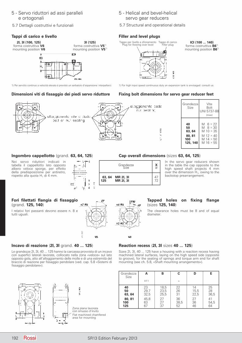
5 - Servo riduttori ad assi paralleli e ortogonali
5 - Helical and bevel-helical servo gear reducers
192 SR13 Edition February 2013
5.7 Dettagli costruttivi e funzionali 5.7 Structural and operational details
Dimensioni viti di fissaggio dei piedi servo riduttore Fixing bolt dimensions for servo gear reducer feet
Ingombro cappellotto (grand. 63, 64, 125)Nei servo riduttori indicati in tabella il cappellotto lato opposto al bero veloce sporge, per effetto della predisposizione per antiretro, rispetto alla quota H1 di 4 mm.
Cap overall dimensions (sizes 63, 64, 125)In the servo gear reducers shown in the table the cap opposite to the high speed shaft projects 4 mm over the dimension H1, owing to the backstop prearrangement.
Grandezza X Size Ø
63, 64 MR 2I, 3I 47 125 MR 2I, 3I 72
Grandezza Vite Size Bolt
UNI 5737-88
40 M 6 3 22 50 M 8 3 30 63, 64 M 10 3 35 80, 81 M 12 3 40 100 M 14 3 50 125, 140 M 16 3 55
Tappi di carico e livello Filler and level plugsTappo per livello a sfioramento
Plug for flowing over levelTappo di carico
Filler plug
1) Per servizio continuo a velocità elevata è previsto un serbatoio d’espansione: interpellarci. 1) For high input speed continuous duty an expansion tank is envisaged: consult us.
Fori filettati flangia di fissaggio (grand. 125, 140)I relativi fori passanti devono essere n. 8 e tutti uguali.
Tapped holes on fixing flange (sizes 125, 140)The clearance holes must be 8 and of equal diameter.
Incavo di reazione (2I, 3I grand. 40 ... 125)Le grandezze 2I, 3I, 40 ... 125 hanno la carcassa provvista di un in cavo con superfici laterali lavorate, collocato nella zona «veloce» sul lato opposto gola, atto all’alloggiamento delle molle e di una estremità del braccio di reazione per fissaggio pendolare (ved. cap. 5.8 «Sistemi di fissaggio pendolare»).
Reaction recess (2I, 3I sizes 40 ... 125)Sizes 2I, 3I, 40 ... 125 have a housing with a reaction recess having machined lateral surfaces, laying on the high speed side (opposite to groove), for the seating of springs and torque arm end for shaft mounting (see ch. 5.8, «Shaft mounting arrangements»).
Grandezza A B C D E Size H11 ≈
40 23 18,5 22 14 25 50 29,7 23,5 26 15,5 28 63, 64 32,5 25,5 31 22,5 36,5 80, 81 45,8 27 36 27 41 100 63 27 38,5 36 54,5 125 67 37 52 46 64
Zona piana lavoratacon smusso d’invitoFlat machined chamferedarea for mounting
2I, 3I (100, 125) 3I (125) ICI (100 ... 140) forma costruttiva V6 forma costruttiva V51) forma costruttiva B61)
mounting position V6 mounting position V51) mounting position B61)
(max)
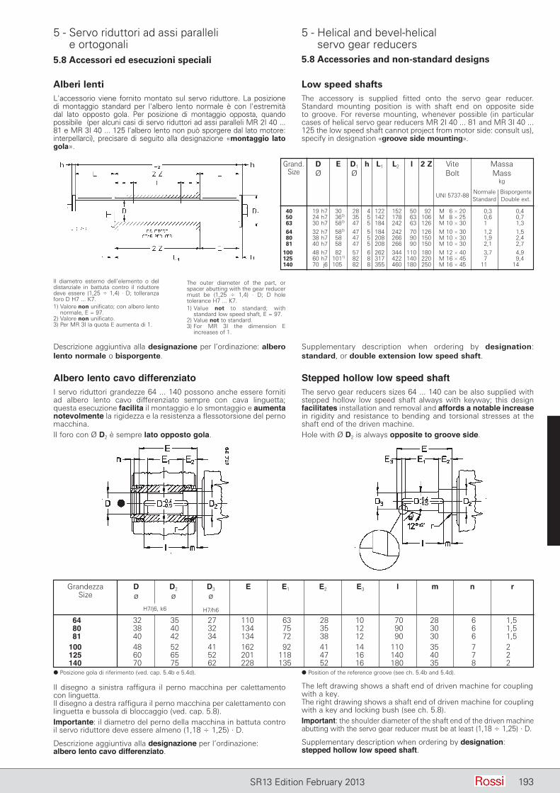
5 - Servo riduttori ad assi paralleli e ortogonali
5 - Helical and bevel-helical servo gear reducers
193SR13 Edition February 2013
5.8 Accessori ed esecuzioni speciali 5.8 Accessories and non-standard designs
Alberi lentiL'accessorio viene fornito montato sul servo riduttore. La posizione di montaggio standard per l'albero lento normale è con l'estremità dal lato opposto gola. Per posizione di montaggio opposta, quando possibile (per alcuni casi di servo riduttori ad assi paralleli MR 2I 40 ... 81 e MR 3I 40 ... 125 l’albero lento non può sporgere dal lato motore: interpellarci), precisare di seguito alla designazione «montaggio lato gola».
Low speed shaftsThe accessory is supplied fitted onto the servo gear reducer. Standard mounting position is with shaft end on opposite side to groove. For reverse mounting, whenever possible (in particular cases of helical servo gear reducers MR 2I 40 ... 81 and MR 3I 40 ... 125 the low speed shaft cannot project from motor side: consult us), specify in designation «groove side mounting».
Grand. D E D1 h L1 L2 l 2 Z Vite Massa Size Ø Ø Bolt Mass kg Normale Bisporgente
UNI 5737-88 Standard Double ext.
40 19 h7 30 28 4 122 152 50 92 M 6 3 20 0,3 0,4 50 24 h7 363) 35 5 142 178 63 106 M 8 3 25 0,6 0,7 63 30 h7 583) 47 5 184 242 63 126 M 10 3 30 1 1,3
64 32 h7 583) 47 5 184 242 70 126 M 10 3 30 1,2 1,5 80 38 h7 58 47 5 208 266 90 150 M 10 3 30 1,9 2,4 81 40 h7 58 47 5 208 266 90 150 M 10 3 30 2,1 2,7
100 48 h7 82 57 6 262 344 110 180 M 12 3 40 3,7 4,9 125 60 h7 1011) 82 8 317 422 140 220 M 16 3 45 7 9,4 140 70 j6 105 82 8 355 460 180 250 M 16 3 45 11 14
Il diametro esterno dell’elemento o del distanziale in battuta contro il riduttore deve essere (1,25 4 1,4) · D; tolleranza foro D H7 ... K7.1) Valore non unificato; con albero lento
normale, E = 97.2) Valore non unificato.3) Per MR 3I la quota E aumenta di 1.
The outer diameter of the part, or spacer abutting with the gear reducer must be (1,25 4 1,4) · D; D hole tolerance H7 ... K7.1) Value not to standard; with
standard low speed shaft, E = 97.2) Value not to standard.3) For MR 3I the dimension E
increases of 1.
Descrizione aggiuntiva alla designazione per l’ordinazione: albero lento normale o bisporgente.
Supplementary description when ordering by designation: standard, or double extension low speed shaft.
Grandezza D D2 D3 E E1 E2 E3 l m n r Size Ø Ø Ø H7/j6, k6 H7/h6
64 32 35 27 110 63 28 10 70 28 6 1,5 80 38 40 32 134 75 35 12 90 30 6 1,5 81 40 42 34 134 72 38 12 90 30 6 1,5 100 48 52 41 162 92 41 14 110 35 7 2 125 60 65 52 201 118 47 16 140 40 7 2 140 70 75 62 228 135 52 16 180 35 8 2d Posizione gola di riferimento (ved. cap. 5.4b e 5.4d). d Position of the reference groove (see ch. 5.4b and 5.4d).
Albero lento cavo differenziatoI servo riduttori grandezze 64 ... 140 possono anche essere forniti ad albero lento cavo differenziato sempre con cava linguetta; questa esecuzione facilita il montaggio e lo smontaggio e aumenta notevolmente la rigidezza e la resistenza a flessotorsione del perno macchina.Il foro con Ø D2 è sempre lato opposto gola.
Stepped hollow low speed shaftThe servo gear reducers sizes 64 ... 140 can be also supplied with stepped hollow low speed shaft always with keyway; this design facilitates installation and removal and affords a notable increase in rigidity and resistance to bending and torsional stresses at the shaft end of the driven machine.Hole with Ø D2 is always opposite to groove side.
Il disegno a sinistra raffigura il perno macchina per calettamento con linguetta.Il disegno a destra raffigura il perno macchina per calettamento con linguetta e bussola di bloccaggio (ved. cap. 5.8).Importante: il diametro del perno della macchina in battuta contro il servo riduttore deve essere almeno (1,18 4 1,25) · D.
Descrizione aggiuntiva alla designazione per l’ordinazione: albero lento cavo differenziato.
The left drawing shows a shaft end of driven machine for coupling with a key.The right drawing shows a shaft end of driven machine for coupling with a key and locking bush (see ch. 5.8).Important: the shoulder diameter of the shaft end of the driven ma chine abutting with the servo gear reducer must be at least (1,18 4 1,25) · D.
Supplementary description when ordering by designation: stepped hollow low speed shaft.
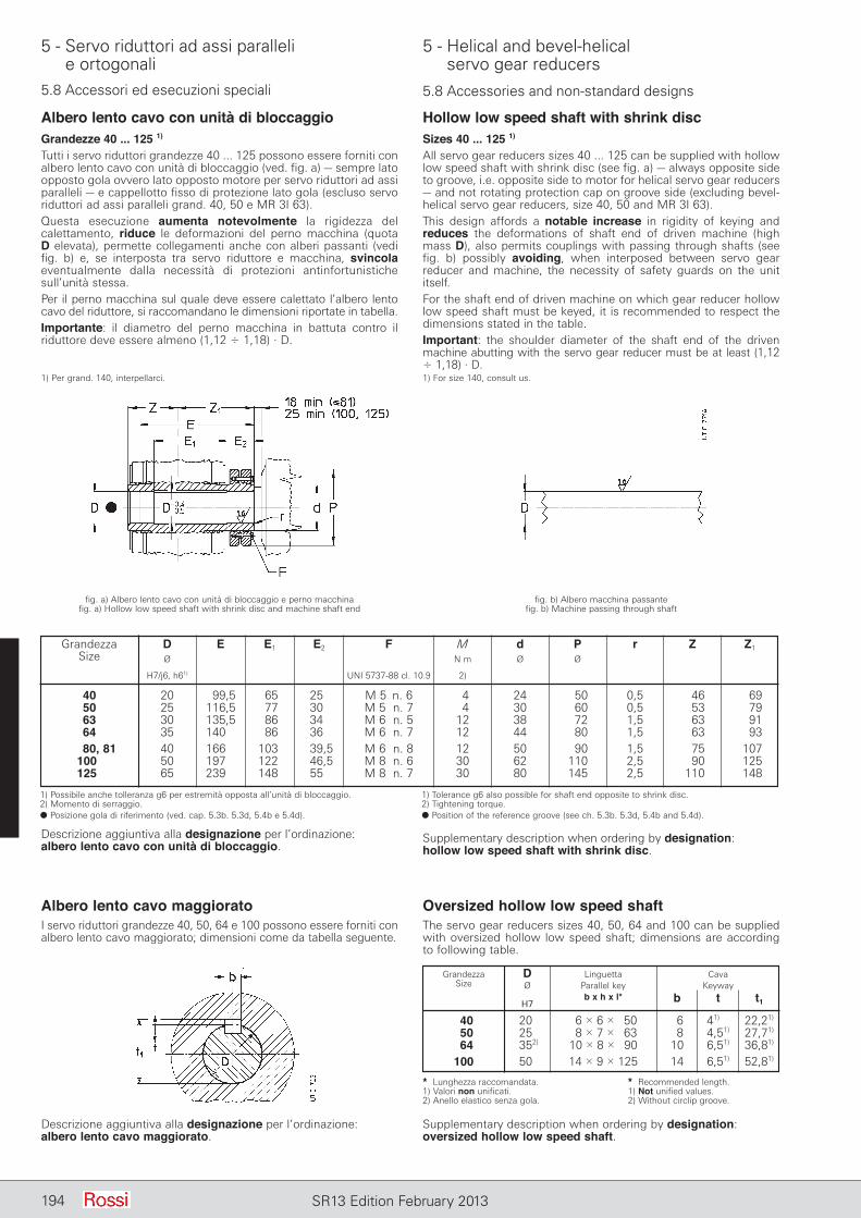
5 - Servo riduttori ad assi paralleli e ortogonali
5 - Helical and bevel-helical servo gear reducers
194 SR13 Edition February 2013
5.8 Accessori ed esecuzioni speciali 5.8 Accessories and non-standard designs
Albero lento cavo con unità di bloccaggioGrandezze 40 ... 125 1)
Tutti i servo riduttori grandezze 40 ... 125 possono essere forniti con albero lento cavo con unità di bloccaggio (ved. fig. a) – sempre lato opposto gola ovvero lato opposto motore per servo riduttori ad assi paralleli – e cappellotto fisso di protezione lato gola (escluso servo riduttori ad assi paralleli grand. 40, 50 e MR 3I 63).Questa esecuzione aumenta notevolmente la rigidezza del calettamento, riduce le deformazioni del perno macchina (quota D elevata), permette collegamenti anche con alberi passanti (vedi fig. b) e, se interposta tra servo riduttore e macchina, svincola eventualmente dalla necessità di protezioni antinfortunistiche sull’unità stessa.Per il perno macchina sul quale deve essere calettato l’albero lento ca vo del riduttore, si raccomandano le dimensioni riportate in tabella.Importante: il diametro del perno macchina in battuta contro il riduttore deve essere almeno (1,12 4 1,18) · D.
1) Per grand. 140, interpellarci.
Hollow low speed shaft with shrink discSizes 40 ... 125 1)
All servo gear reducers sizes 40 ... 125 can be supplied with hollow low speed shaft with shrink disc (see fig. a) – always opposite side to groove, i.e. opposite side to motor for helical servo gear reducers – and not rotating protection cap on groove side (excluding bevel-helical servo gear reducers, size 40, 50 and MR 3I 63).This design affords a notable increase in rigidity of keying and reduces the deformations of shaft end of driven machine (high mass D), also permits couplings with passing through shafts (see fig. b) possibly avoiding, when interposed between servo gear reducer and machine, the necessity of safety guards on the unit itself.For the shaft end of driven machine on which gear reducer hollow low speed shaft must be keyed, it is recommended to respect the dimensions stated in the table.Important: the shoulder diameter of the shaft end of the driven ma chine abutting with the servo gear reducer must be at least (1,12 4 1,18) · D.1) For size 140, consult us.
fig. a) Albero lento cavo con unità di bloccaggio e perno macchinafig. a) Hollow low speed shaft with shrink disc and machine shaft end
fig. b) Albero macchina passantefig. b) Machine passing through shaft
Grandezza D E E1 E2 F M d P r Z Z1
Size Ø N m Ø Ø H7/j6, h61) UNI 5737-88 cl. 10.9 2)
40 20 99,5 65 25 M 5 n. 6 4 24 50 0,5 46 69 50 25 116,5 77 30 M 5 n. 7 4 30 60 0,5 53 79 63 30 135,5 86 34 M 6 n. 5 12 38 72 1,5 63 91 64 35 140 86 36 M 6 n. 7 12 44 80 1,5 63 93 80, 81 40 166 103 39,5 M 6 n. 8 12 50 90 1,5 75 107 100 50 197 122 46,5 M 8 n. 6 30 62 110 2,5 90 125 125 65 239 148 55 M 8 n. 7 30 80 145 2,5 110 148
1) Possibile anche tolleranza g6 per estremità opposta all’unità di bloccaggio.2) Momento di serraggio.d Posizione gola di riferimento (ved. cap. 5.3b. 5.3d, 5.4b e 5.4d).
1) Tolerance g6 also possible for shaft end opposite to shrink disc.2) Tightening torque.d Position of the reference groove (see ch. 5.3b. 5.3d, 5.4b and 5.4d).
Descrizione aggiuntiva alla designazione per l’ordinazione: albero lento cavo con unità di bloccaggio.
Supplementary description when ordering by designation: hollow low speed shaft with shrink disc.
Albero lento cavo maggioratoI servo riduttori grandezze 40, 50, 64 e 100 possono essere forniti con albero lento cavo maggiorato; dimensioni come da tabella seguente.
Oversized hollow low speed shaftThe servo gear reducers sizes 40, 50, 64 and 100 can be supplied with oversized hollow low speed shaft; dimensions are according to following table.
Descrizione aggiuntiva alla designazione per l’ordinazione: albero lento cavo maggiorato.
Supplementary description when ordering by designation: oversized hollow low speed shaft.
Grandezza D Linguetta Cava Size Ø Parallel key Keyway b x h x l* b t t1 H7
40 20 6 3 6 3 50 6 41),0 22,21)
50 25 8 3 7 3 63 8 4,51) 27,71)
64 352) 10 3 8 3 90 10 6,51) 36,81)
100 50 14 3 9 3 125 14 6,51) 52,81)
* Lunghezza raccomandata.1) Valori non unificati.2) Anello elastico senza gola.
* Recommended length.1) Not unified values.2) Without circlip groove.
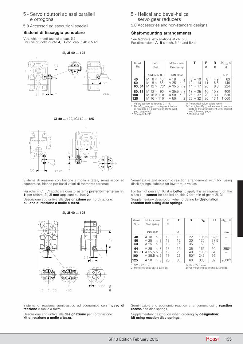
5 - Servo riduttori ad assi paralleli e ortogonali
5 - Helical and bevel-helical servo gear reducers
195SR13 Edition February 2013
5.8 Accessori ed esecuzioni speciali 5.8 Accessories and non-standard designs
Sistemi di fissaggio pendolareVed. chiarimenti tecnici al cap. 6.6.Per i valori delle quote A, B ved. cap. 5.4b e 5.4d.
Shaft-mounting arrangementsSee technical explanations at ch. 6.6.For dimensions A, B see ch. 5.4b and 5.4d.
Grand. Vite Molla a tazza T F R M2max Size Bolt Disc spring Ø 1) 2) UNI 5737-88 DIN 2093 N m
40 M 6 3 40 A 18 n. 2 8 4 10 8 4,9 63 50 M 8 3 55 A 25 n. 2 10 4 14 11 6,5 140 63, 64 M 12 3 70* A 35,5 n. 2 14 4 17 20 8,8 224
80, 81 M 12 3 90 A 35,5 n. 3 18 4 25 16 10,8 400 100 M 16 3 110 A 50 n. 2 25 4 32 20 13,1 630 125 M 16 3 110 A 50 n. 2 25 4 32 20 13,1 1 000
1) Valore teorico: tolleranza 0 4 -1.2) Per M2 max maggiori impiegare 2 bulloni
di reazione o il sistema con staffa (ved. pag. seguente).
* Vite modificata.
1) Theoretical value: tolerance 0 4 -1.2) For higher M2 max values, use 2 reaction
bolts or the arrangement with bracket (see following page).
* Modified bolt.
2I, 3I 40 ... 125
CI 40 ... 100, ICI 40 ... 125
Per rotismi CI, ICI applicare questo sistema preferibilmente sui lati 1; per rotismi 2I, 3I non applicare sul lato 2.Descrizione aggiuntiva alla designazione per l’ordinazione: bullone di reazione a molle a tazza.
For train of gears CI, ICI it is better to apply this arrangement on the sides 1; it cannot be applied on side 2 for train of gears 2I, 3I.Supplementary description when ordering by designation: reaction bolt using disc springs.
Sistema di reazione con bullone a molla a tazza, semielastico ed economico, idoneo per bassi valori di momento torcente.
Semi-flexible and economic reaction arrangement, with bolt using disck springs, suitable for low torque values.
Descrizione aggiuntiva alla designazione per l’ordinazione: kit di reazione a molle a tazza.
Supplementary description when ordering by designation: kit using reaction disc springs.
Sistema di reazione semielastico ed economico con incavo di reazione e molle a tazza.
Semi-flexible and economic reaction arrangement using reaction recess and disc springs.
2I, 3I 40 ... 125
Grand. Molla a tazza F T S xR U M2max
Disc spring Ø DIN 2093 h11 N m
40 A 18 n. 3 10 10 22 105,5 32,5 – 50 A 25 n. 3 13 12 30 130 37,5 – 63 A 25 n. 3 13 15 35 163 50 – 64 A 25 n. 3 13 15 35 165 50 3502)
80, 81 A 35,5 n. 3 19 20 40 198,5 54 – 100 A 35,5 n. 6 19 25 501) 246 66 – 125 A 50 n. 3 26 30 60 306 82 26002)
1) S/2 = 22,5 mm.2) Per forma costruttiva B3 e B8.
1) S/2 = 22,5 mm.2) For mounting positions B3 and B8.
Size
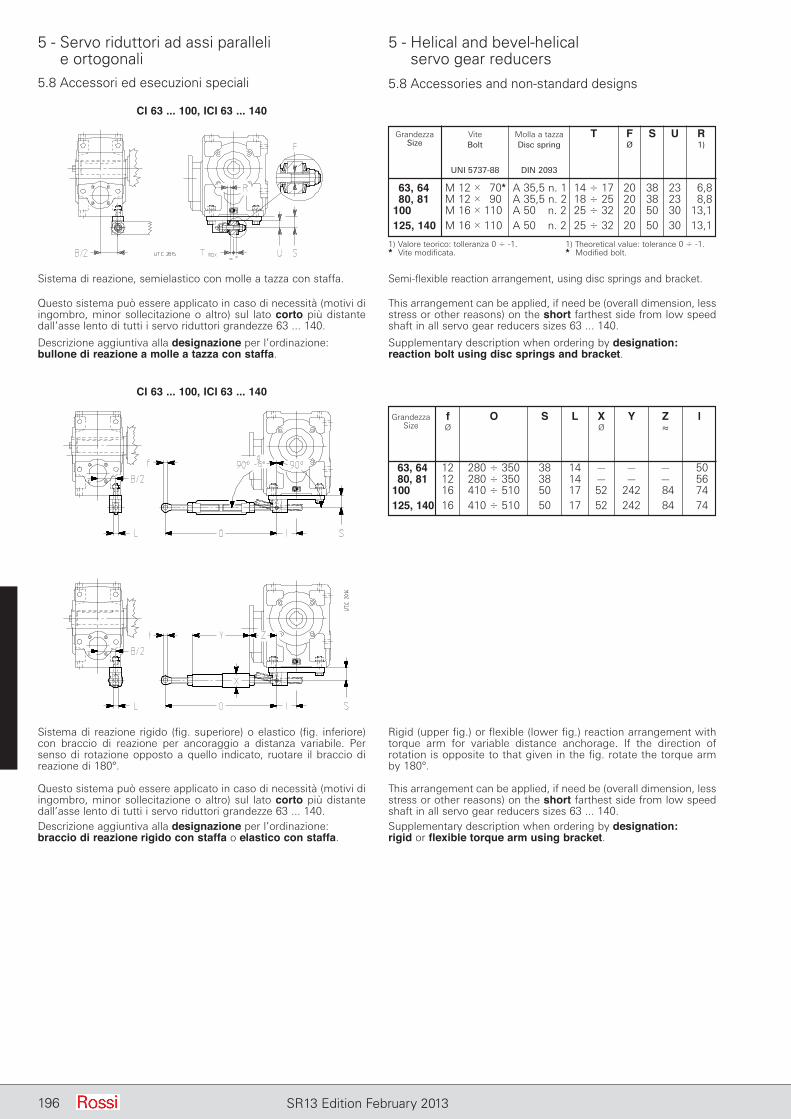
5 - Servo riduttori ad assi paralleli e ortogonali
5 - Helical and bevel-helical servo gear reducers
196 SR13 Edition February 2013
5.8 Accessori ed esecuzioni speciali 5.8 Accessories and non-standard designs
CI 63 ... 100, ICI 63 ... 140
Grandezza f O S L X Y Z l Size Ø Ø ≈
63, 64 12 280 4 350 38 14 – – – 50 80, 81 12 280 4 350 38 14 – – – 56 100 16 410 4 510 50 17 52 242 84 74 125, 140 16 410 4 510 50 17 52 242 84 74
Questo sistema può essere applicato in caso di necessità (motivi di ingombro, minor sollecitazione o altro) sul lato corto più distante dall’asse lento di tutti i servo riduttori grandezze 63 ... 140.Descrizione aggiuntiva alla designazione per l’ordinazione: braccio di reazione rigido con staffa o elastico con staffa.
This arrangement can be applied, if need be (overall dimension, less stress or other reasons) on the short farthest side from low speed shaft in all servo gear reducers sizes 63 ... 140.Supplementary description when ordering by designation: rigid or flexible torque arm using bracket.
CI 63 ... 100, ICI 63 ... 140
Questo sistema può essere applicato in caso di necessità (motivi di ingombro, minor sollecitazione o altro) sul lato corto più distante dall’asse lento di tutti i servo riduttori grandezze 63 ... 140.
Descrizione aggiuntiva alla designazione per l’ordinazione: bullone di reazione a molle a tazza con staffa.
This arrangement can be applied, if need be (overall dimension, less stress or other reasons) on the short farthest side from low speed shaft in all servo gear reducers sizes 63 ... 140.
Supplementary description when ordering by designation: reaction bolt using disc springs and bracket.
Grandezza Vite Molla a tazza T F S U R Size Bolt Disc spring Ø 1) UNI 5737-88 DIN 2093
63, 64 M 12 3 70* A 35,5 n. 1 14 4 17 20 38 23 6,8 80, 81 M 12 3 90 A 35,5 n. 2 18 4 25 20 38 23 8,8 100 M 16 3 110 A 50 n. 2 25 4 32 20 50 30 13,1 125, 140 M 16 3 110 A 50 n. 2 25 4 32 20 50 30 13,1
1) Valore teorico: tolleranza 0 4 -1.* Vite modificata.
1) Theoretical value: tolerance 0 4 -1.* Modified bolt.
Sistema di reazione, semielastico con molle a tazza con staffa. Semi-flexible reaction arrangement, using disc springs and bracket.
Sistema di reazione rigido (fig. superiore) o elastico (fig. inferiore) con braccio di reazione per ancoraggio a distanza variabile. Per senso di rotazione opposto a quello indicato, ruotare il braccio di reazione di 180°.
Rigid (upper fig.) or flexible (lower fig.) reaction arrangement with torque arm for variable distance anchorage. If the direction of rotation is opposite to that given in the fig. rotate the torque arm by 180°.
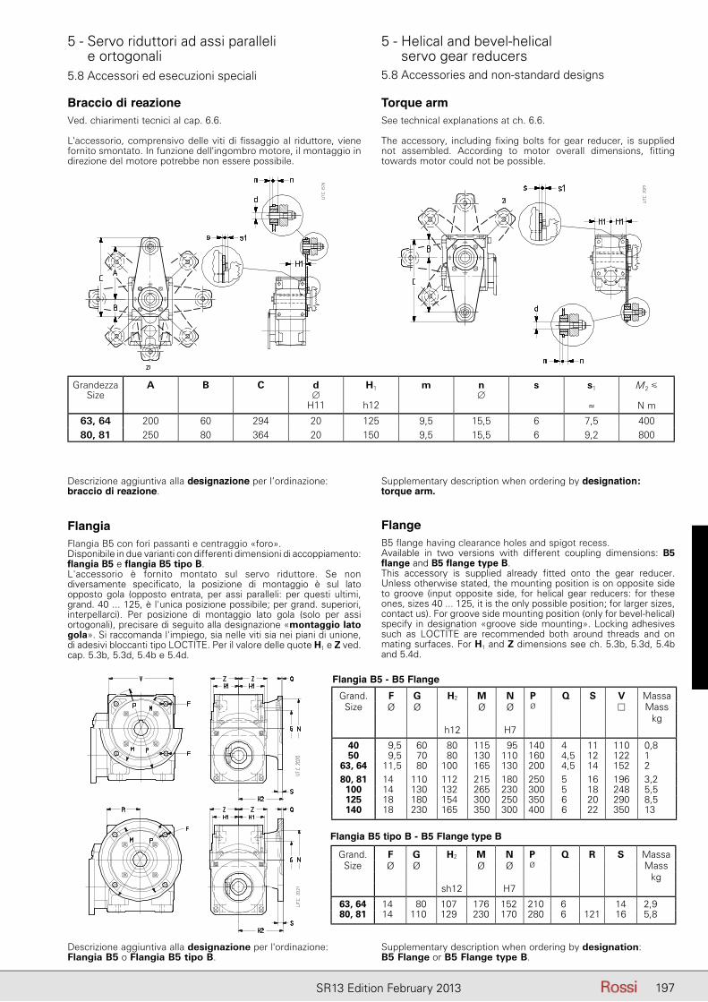
5 - Servo riduttori ad assi paralleli e ortogonali
5 - Helical and bevel-helical servo gear reducers
197SR13 Edition February 2013
5.8 Accessori ed esecuzioni speciali 5.8 Accessories and non-standard designs
Braccio di reazioneVed. chiarimenti tecnici al cap. 6.6.
L'accessorio, comprensivo delle viti di fissaggio al riduttore, viene fornito smontato. In funzione dell'ingombro motore, il montaggio in direzione del motore potrebbe non essere possibile.
Torque armSee technical explanations at ch. 6.6.
The accessory, including fixing bolts for gear reducer, is supplied not assembled. According to motor overall dimensions, fitting towards motor could not be possible.
GrandezzaSize
A B C d∅
H11
H1
h12
m n∅
s s1
≈
M2 �
N m
63, 64 200 60 294 20 125 9,5 15,5 6 7,5 400
80, 81 250 80 364 20 150 9,5 15,5 6 9,2 800
Descrizione aggiuntiva alla designazione per l’ordinazione: braccio di reazione.
Supplementary description when ordering by designation: torque arm.
FlangiaFlangia B5 con fori passanti e centraggio «foro».Disponibile in due varianti con differenti dimensioni di accoppiamento: flangia B5 e flangia B5 tipo B.L'accessorio è fornito montato sul servo riduttore. Se non diversamente specificato, la posizione di montaggio è sul lato opposto gola (opposto entrata, per assi paralleli: per questi ultimi, grand. 40 ... 125, è l'unica posizione possibile; per grand. superiori, interpellarci). Per posizione di montaggio lato gola (solo per assi ortogonali), precisare di seguito alla designazione «montaggio lato gola». Si raccomanda l'impiego, sia nelle viti sia nei piani di unione, di adesivi bloccanti tipo LOCTITE. Per il valore delle quote H1 e Z ved. cap. 5.3b, 5.3d, 5.4b e 5.4d.
FlangeB5 flange having clearance holes and spigot recess.Available in two versions with different coupling dimensions: B5 flange and B5 flange type B.This accessory is supplied already fitted onto the gear reducer. Unless otherwise stated, the mounting position is on opposite side to groove (input opposite side, for helical gear reducers: for these ones, sizes 40 ... 125, it is the only possible position; for larger sizes, contact us). For groove side mounting position (only for bevel-helical) specify in designation «groove side mounting». Locking adhesives such as LOCTITE are recommended both around threads and on mating surfaces. For H1 and Z dimensions see ch. 5.3b, 5.3d, 5.4b and 5.4d.
Flangia B5 - B5 Flange
Flangia B5 tipo B - B5 Flange type B
Descrizione aggiuntiva alla designazione per l'ordinazione: Flangia B5 o Flangia B5 tipo B.
Supplementary description when ordering by designation: B5 Flange or B5 Flange type B.
Grand. F G H2 M N P Q S V MassaSize Ø Ø Ø Ø Ø � Mass
kgh12 H7
40 9,5 60 80 115 95 140 4 11 110 0,850 9,5 70 80 130 110 160 4,5 12 122 1
63, 64 11,5 80 100 165 130 200 4,5 14 152 280, 81 14 110 112 215 180 250 5 16 196 3,2
100 14 130 132 265 230 300 5 18 248 5,5125 18 180 154 300 250 350 6 20 290 8,5140 18 230 165 350 300 400 6 22 350 13
Grand. F G H2 M N P Q R S MassaSize Ø Ø Ø Ø Ø Mass
kgsh12 H7
63, 64 14 80 107 176 152 210 6 14 2,980, 81 14 110 129 230 170 280 6 121 16 5,8

5 - Servo riduttori ad assi paralleli e ortogonali
5 - Helical and bevel-helical servo gear reducers
198 SR13 Edition February 2013
5.8 Accessori ed esecuzioni speciali 5.8 Accessories and non-standard designs
Rosetta albero lento cavoTutti i servo riduttori possono essere forniti di rosetta, anello elastico (escluse grandezze 40 ... 63), vite per il fissaggio assiale e cappellotto di protezione (escluso servo riduttori ad assi paralleli grand. 40, 50).Descrizione aggiuntiva alla designazione per l’ordinazione: rosetta albero lento cavo.
Rosetta albero lento cavo con anelli o bussola di bloccaggioTutti i servo riduttori possono essere forniti di rosetta, anello elastico (escluse grandezze 40 ... 63), anelli di bloccaggio (grandezze 40 ... 63) o bussola di bloccaggio (grandezze 64 ... 140), vite per il fissaggio assiale e cappellotto di protezione (escluso lato entrata servo riduttori ad assi paralleli grand. 40, 50).Descrizione aggiuntiva alla designazione per l’ordinazione: rosetta albero lento cavo con anelli o bussola di bloccaggio.
Protezione albero lento cavoI servo riduttori, grandezze 40 ... 140, possono essere forniti del solo cappellotto di protezione della zona non utilizzata dell’albero lento cavo. Montaggio non possibile sul lato entrata servo riduttori ad assi paralleli grandezza 40, 50.Non utilizzabile con l’albero lento normale.Descrizione aggiuntiva alla designazione per l’ordinazione: protezione albero lento cavo.
Hollow low speed shaft washerAll servo gear reducers can be supplied with washer, circlip (excluding sizes 40 ... 63), bolt for axial fastening and protection cap (excluding input side of helical and bevel-helical servo gear reducers, sizes 40, 50).Supplementary description when ordering by designation: hollow low speed shaft washer.
Hollow low speed shaft washer with locking rings or bushAll servo gear reducers can be supplied with washer, circlip (excluding sizes 40 ... 63), locking rings (sizes 40 ... 63) or locking bush (sizes 64 ... 140), bolt for axial fastening and protection cap (excluding helical servo gear reducers, sizes 40, 50).Supplementary description when ordering by designation: hollow low speed shaft washer with locking rings or bush.
Hollow low speed shaft protectionThe servo gear reducers, sizes 40 ... 140, can be supplied with only the protection cap for the area not utilized by the hollow low speed shaft. Mounting not possible on input face for helical servo gear reducers sizes 40, 50.It cannot be used with standard low speed shaff.Supplementary description when ordering by designation: hollow low speed shaft protection.
Protezione albero lento cavo Cappellotto di protezione della zona non utilizzata dell'albero lento cavo, di materiale plastico (polipropilene PP, colore nero).L'accessorio viene fornito smontato e completo di viti per il fissaggio. Si raccomanda l'impiego di adesivi bloccanti sulle viti di fissaggio.
Hollow low speed shaft protectionProtection of hollow low speed shaft free area, made of plastic (polypropilene PP material color black). The accessory is supplied disassembled and complete with fastening screws. We recommend the use of locking adhesive on the screws.
STANDARDFIT STANDARDFIT
GrandezzaSize
P P0 X s VitiScrews
MserraggioMtightening
UNI 5931
40 90 48 20,5 1,5 M5×14 1,550 105 50 20,5 1,6 M6×18 2,8
63, 64 120 61 24 1,7 M8×20 6,3
80, 81 160 78 27,5 1,8 M10×20 12,3
Codice di esecuzione speciale per la designazione: Protezione albero lento cavo STANDARDFIT
Suppementary description when ordering by designation: STANDARDFIT hollow low speed shaft protections
Gioco ridottoTutti i servo riduttori possono essere forniti con gioco angolare asse lento ridotto: valori indicati al cap. 5.7. Descrizione aggiuntiva alla designazione per l'ordinazione: gioco ridotto.
Reduced backlashAll servo gear reducers can be supplied with reduced low speed shaft angular backlash: values stated on ch. 5.7.Supplementary description when ordering by designation: reduced backlash
Giunto con cava linguetta (servo riduttore tipo R)Descrizione aggiuntiva alla designazione per l’ordinazione: giunto con cava linguetta1).
1) Previa indicazione da parte del cliente della normativa di riferimento.
Coupling with keyway (servo gear reducer type R)Supplementary description when ordering by designation: coupling with keyway1).
1) Upon customer's statement of the standards considered.
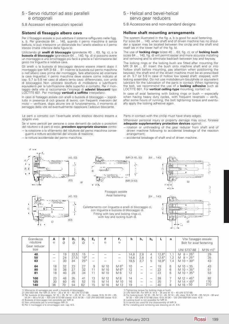
5 - Servo riduttori ad assi paralleli e ortogonali
5 - Helical and bevel-helical servo gear reducers
199SR13 Edition February 2013
5.8 Accessori ed esecuzioni speciali 5.8 Accessories and non-standard designs
Sistemi di fissaggio albero cavoPer il fissaggio assiale si può adottare il sistema raffigurato nelle figg. a, b. Per grandezze 64 ... 140, quando il perno macchina è senza battuta, si può interporre un distanziale tra l’anello elastico e il perno stesso (metà inferiore della figura b).Utilizzando gli anelli di bloccaggio (grandezze 40 ... 63, fig. c), o la bussola di bloccaggio (grandezze 64 ... 140, fig. d) si possono avere un montaggio e uno smontaggio più facili e precisi e l’eliminazione del gioco tra linguetta e relativa cava.Gli anelli o la bussola di bloccaggio devono essere inseriti dopo il montaggio (per MR 3I 64 ... 81 inserire la bussola sul perno macchina o nell’albero cavo prima del montaggio, fare attenzione ad orientare la cava linguetta); il perno macchina deve essere come indicato al cap. 5.7 (o 5.8 nel caso di albero lento cavo: differenziato, con unità di bloccaggio). Non utilizzare bisolfuro di molibdeno o lubrificanti equivalenti per la lubrificazione delle superfici a contatto. Per il mon-taggio della vite si raccomanda l’impiego di adesivi bloccanti tipo LOCTITE 601. Per montaggi verticali a soffitto interpellarci.In caso di fissaggio assiale con anelli o bussola di bloccaggio – soprat-tutto in presenza di cicli gravosi di lavoro, con frequenti inversioni del moto – verificare, dopo alcune ore di funzionamento, il mo mento di serraggio della vite ed eventualmente riapplicare l’adesivo bloccante.
Hollow shaft mounting arrangementsThe system illustrated in the fig. a, b is good for axial fastening.For sizes 64 ... 140, when shaft end of driven machine has no shoul-der a spacer may be located between the circlip and the shaft end itself (as in the lower half of the fig. b).The use of locking rings (sizes 40 ... 63, fig. c), or of locking bush (sizes 64 ... 140, fig. d) will permit easier and more accurate installing and removing and to eliminate backlash between key and keyway.The locking rings or the locking bush are fitted after mounting (for MR 3I 64 ... 81 insert the bush onto machine shaft end or into hollow shaft before mounting, pay attention when positioning the keyway); the shaft end of the driven machine must be as prescribed at ch. 5.7 (or 5.8 in case of hollow low speed shaft: stepped, with locking assembly). Do not use molybdenum bisulphide or equivalent lubricant for the lubrication of the parts in contact. When tightening the bolt, we recommend the use of a locking adhesive such as LOCTITE 601. For vertical ceiling-type mounting, contact us.In case of axial fastening with locking rings or bush – especially when having heavy duty cycles, with frequent reversals – verify, after some hours of running, the bolt tightening torque and eventu-ally apply the locking adhesive again.
Le parti a contatto con l’eventuale anello elastico devono essere a spigolo vivo.Se vi sono pericoli per persone o cose derivanti da cadute o proiezioni del riduttore o di parti di esso, prevedere appropriate sicurezze contro:– la rotazione o lo sfilamento del riduttore dal perno macchina conse-
guenti a rotture accidentali del vincolo di reazione;– la rottura accidentale del perno macchina.
Parts in contact with the circlip must have sharp edges.Whenever personal injury or property damage may occur, foresee adequate supplementary protection devices against:– rotation or un threading of the gear reducer from shaft end of
driven machine following to accidental breakage of the reaction arrangement;
– accidental breakage of shaft end of driven machine.
1) Momento di serraggio per anelli o bussola di bloccaggio.2) UNI 5931-84. Per MR 3I: M 8 3 35 e M 10 3 40 UNI 5737-88.3) Per bussola di bloccaggio: M 10 3 35, M 12 3 45, M 14 3 45, classe 10.9; M 20 3 65,
M 24 3 80 e M 30 3 100 UNI 5737-88 classe 10.9; M 36 3 120 UNI 5931-84 classe 10.9.4) Bussola di bloccaggio non possibile per MR 3I.5) Non utilizzabile per lo smontaggio MR 3I.6) Per il montaggio e lo smontaggio ved. cap. 6.5.
1) Tightening torque for locking rings or bush.2) UNI 5931-84. For MR 3I: M 8 3 35 and M 10 3 40 UNI 5737-88.3) For locking bush: M 10 3 35, M 12 3 45, M 14 3 45, class 10.9; M 20 3 65, M 24 3 80 and
M 30 3 100 UNI 5737-88 class 10.9; M 36 3 120 UNI 5931-84 class 10.9.4) Locking bush is not possible for MR 3I.5) It cannot be used for the disassembly of MR 3I.6) For installing and removing see drawing on ch. 6.5.
Grandezza A D D1 D3 E3 F F1 h h1 h2 L n Vite fissaggio assiale riduttore 6) Ø Ø Ø ≈ 6) 6) Bolt for axial fastening Gear reducer size UNI 5737-88 M [N m]1)
40 – 19 22,5 15 – – – 14,8 2,8 4 12,64) 1,1 M 8 3 252) 29 50 – 24 27,5 194) – – – 14,8 2,8 4 12,64) 1,2 M 8 3 252) 35 63 – 30 34 254) – – – 18,5 3,7 5 18,94) 1,4 M 10 3 302) 43
64 18 32 23 27 9 M 10 M 65) 10 – – 19 6 M 10 3 35 43 80 18 38 27 32 11 M 10 M 65) 12 – – 23 6 M 10 3 353) 51 81 18 40 28 34 11 M 10 M 60 12 – – 23 6 M 10 3 353) 53
100 23 48 35 41 13 M 12 M 80 14 – – 28 7 M 12 3 453) 92 125 30 60 45 52 15 M 14 M 10 16 – – 35 7 M 14 3 453) 170 140 36 70 54 62 15 M 16 M 12 19 – – 40 8 M 16 3 50 210
Fissaggio assialeAxial fastening
Callettamento con linguetta e anelli di bloccaggio c), con linguetta e bussola di bloccaggio d).
Fitting with key and locking rings c), with key and locking bush d).
a) b)
c) d)
(64 ... 140)(MR 3I 40, 50)(40, 50)
(63)
(63)
(40, 50) (64 ... 140)
(MR 3I 63)
5 - Servo riduttori ad assi paralleli e ortogonali
5 - Helical and bevel-helical servo gear reducers
200 SR13 Edition February 2013200 SR13 Edition January 2013200 SR13 Edition February 2013
Varie― Carcassa con flangia B14 su due facce (rotismo 2I, 3I grandezze
63 ... 125).― Anelli di tenuta speciali; doppia tenuta asse lento (grandezze ≥
80).― Pompa lubrificazione cuscinetti per grand. 100 e 125.― Termostato bimetallico per grand. 100 e 125 per il controllo della
temperatura massima ammissibile per l'olio.
Miscellaneous― Housing with B14 flange on two faces (train of gears 2I, 3I and
4I sizes 63 ... 125).― Special seal rings; double seal on low speed shaft (sizes ≥ 80).― Bearing lubrication pump for sizes 100 and 125.― Bi-metal type thermostat for the control of the maximum
admissible oil temperature for sizes 100 and 125.
5.8 Accessori ed esecuzioni speciali 5.8 Accessories and non-standard designs

201SR13 Edition February 2013
Installazione e manutenzioneInstallation and maintenance
Indice6.1 - Avvertenze generali sulla sicurezza ................. 2026.2 - Condizioni di impiego ...................................... 2026.3 - Installazione .................................................... 2036.4 - Montaggio servomotore ................................. 2046.5 - Montaggio di organi sull'estremità d'albero .... 2086.6 - Sistemi di fissaggio pendolare ........................ 2106.7 - Lubrificazione .................................................. 2126.8 - Targhe ............................................................. 215
Contents6.1 - General safety instructions ............................. 2026.2 - Operating conditions ....................................... 2026.3 - Installation ....................................................... 2036.4 - Servomotor mounting ..................................... 2046.5 - Fitting of components to shaft end ................. 2086.6 - Shaft mounting arrangements ........................ 2106.7 - Lubrication ...................................................... 2126.8 - Name plates .................................................... 215
6
6 - Installazione e manutenzione 6 - Installation and maintenance
202 SR13 Edition February 2013
6.1 Avvertenze generali sulla sicurezzaI servo riduttori presentano parti pericolose in quanto possono essere:– poste sotto tensione;– a temperatura superiore a +50 °C;– in movimento durante il funzionamento;– eventualmente rumorose (livelli sonori > 85 dB (A)).
Un'installazione non corretta, un uso improprio, la rimozione delle protezioni, lo scollegamento dei dispositivi di protezione, la carenza di ispezioni e manutenzione, i collegamenti impropri, possono causare danni gravi a persone o cose. Pertanto, il componente deve essere movimentato, installato, messo in servizio, gestito, ispezionato, manutenuto e riparato esclusivamente da personale responsabile qualificato (definizione secondo IEC 364).Si raccomanda di attenersi a tutte le istruzioni del presente catalogo, alle istruzioni e avvertenze che accompagnano ogni servo riduttore, alle istruzioni relative all'impianto, alle vigenti disposizioni legislative di sicurezza, e a tutte le normative applicabili in materia di corretta installazione.Attenzione! Componenti in esecuzione speciale o con varianti costruttive possono differire nei dettagli rispetto a quelli descritti e possono richiedere informazioni aggiuntive.Attenzione! Per eventuali chiarimenti e/o informazioni ulteriori, interpellare Rossi, specificando tutti i dati di targa.I servo riduttori del presente manuale sono normalmente destinati ad essere impiegati in aree industriali: protezioni supplementari eventualmente necessarie per impieghi diversi devono essere adottate e garantite da chi è responsabile dell'installazione.IMPORTANTE: i componenti forniti da Rossi sono destinati ad essere incorporati in apparecchi o sistemi finiti e ne è vietata la messa in servizio fino a quando l'apparecchio o il sistema nel quale il componente è stato incorporato non sia stato dichiarato conforme: – alla Direttiva Macchine (Dichiarazione di incorporazione -
Direttiva 2006/42/CE Art. 4.2 - II B) e successivi aggiornamenti; in particolare, eventuali protezioni antiinfortunistiche per estremità d'albero non utilizzate e per passaggi copriventola eventualmente accessibili (o altro), sono a cura dell'Acquirente;
– alla Direttiva Compatibilità elettromagnetica (EMC) 2004/108/CE e successivi aggiornamenti.
Qualunque tipo di operazione sul servo riduttore o su componenti ad esso connessi deve avvenire a macchina ferma: scollegare il motore (compresi gli equipaggiamenti ausiliari) dall'alimentazione, il servo riduttore dal carico e assicurarsi che si siano attivati i sistemi di sicurezza contro ogni avviamento involontario e, ove si renda necessario, prevedere dispositivi meccanici di bloccaggio (da rimuovere prima della messa in servizio).In caso di funzionamento anomalo (aumento di temperatura, rumorosità inusuale, ecc.) arrestare immediatamente la macchina.I prodotti relativi a questo catalogo corrispondono al livello tecnico raggiunto al momento della stampa del manuale stesso. Rossi si riserva il diritto di apportare, senza preavviso, le modifiche ritenute opportune per il miglioramento del prodotto.
6.2 Condizioni di impiegoI servo riduttori sono progettati per utilizzo in applicazioni industriali in accordo con i dati di targa, temperature ambiente 0 ÷ +40 °C (con punte a - 10 °C e + 50 °C), altitudine massima 1 000 m.Per funzionamento a temperatura ambiente maggiore di +40 °C o minore di 0 °C interpellare Rossi.Non è consentito l'impiego in atmosfere aggressive, con pericolo di esplosione, ecc.Le condizioni di funzionamento devono corrispondere ai dati di targa.
6.1 General safety instructionsServo gear reducers present dangerous parts because they may be:– live;– operating at temperature higher than +50 °C;– rotating during the operation;– noisy (sound levels > 85 dB (A)).An incorrect installation, an improper use, the removing or disconnection of protection devices, the lack of inspections and maintenance, improper connections may cause severe personal injury or property damage. Therefore the component must be moved, installed, commissioned, handled, controlled, serviced and repaired exclusively by responsible qualified personnel (definition to IEC 364).It is recommended to pay attention to all instructions of present catalog, all instructions and warnings accompanying each servo gear reducer, instructions relevant to the system, all existing safety laws and standards concerning correct installation.Attention! Components in non-standard design or with constructve variations may differ in the details from the ones described here following and may require additional information.Attention! For any clarification and/or additional information consult Rossi and specify all name plate data.Servo gear reducers of present catalog are normally suitable for installations in industrial areas: additional protection measures, if necessary for different employs, must be adopted and assured by the person responsible for the installation.IMPORTANT: the components supplied by Rossi are intended to be incorporated into an equipment or a complete system and should not be put into service before the equipment or the finite system complies with: – the Machinery directive (Declaration of incorporation - Directive
2006/42/EC Art. 4.2 - II B) and subsequent updatings; in particular, possible safety guards for shaft ends not being used and for eventually accessible fan cover passages (or other) are the Buyer's responsibility;
– the Electromagnetic compatibility (EMC) directive 2004/108/EC and subsequent updatings.
When operating on servo gear reducer or on components connected to it the machine must be at rest: disconnect motor (including auxiliary equipment) from power supply, servo gear reducer from load, be sure that safety systems are on against any accidental starting and, if necessary, pre-arrange mechanical locking devices (to be removed before commissioning).If deviations from normal operation occur (temperature increase, unusual noise, etc.) immediately switch off the machine.The products relevant to this catalog correspond to the technical level reached at the moment the handbook is printed. Rossi reserves the right to introduce, without notice, the necessary changes for the increase of product performances.
6.2 Operating conditionsServo gear reducers are designed for industrial applications according to name plate data, at ambient temperature 0 ÷ +40 °C (with peaks at -10 °C and + 50 °C), maximum altitude 1 000 m. For ambient temperature higher than +40 °C or lower than 0 °C, consult Rossi.Not allowed running conditions: application in aggressive environments having explosion danger, etc.Ambient conditions must comply with specifications stated on name plate.
6 - Installazione e manutenzione 6 - Installation and maintenance
203SR13 Edition February 2013
6.3 InstallazionePrima di effettuare l'installazione, verificare che:– non vi siano stati danni durante l'immagazzinamento o il trasporto;– l'esecuzione sia adeguata all'ambiente (temperatura, atmosfera,
ecc.);– la forma costruttiva di impiego corrisponda a quella indicata in targa.
Attenzione! Per il sollevamento e la movimentazione del servo riduttore utilizzare i fori passanti o filettati della carcassa servo riduttore, accertarsi che il carico sia convenientemente bilanciato e che siano disponibili apparecchiature di sollevamento, sistemi di aggancio e cavi di portata adeguata. All'occorrenza l'entità delle masse è indicata ai capp. 3.4, 3.6, 4.4, 5.3b, 5.3d, 5.4b e 5.4d.Non utilizzare, per il sollevamento dei servo riduttori, gli eventuali golfari del servomotore.Montare il servo riduttore in modo che non subisca vibrazioni. Assicurarsi che la struttura sulla quale viene fissato il servo riduttore sia piana, livellata e sufficientemente dimensionata per garantire la stabilità del fissaggio e l'assenza di vibrazioni (sono accettabili velocità di vibrazione veff ≤ 3,5 mm/s per grand. ≤ 100 e veff ≤ 4,5 mm/s per grand. ≥ 125), tenuto conto di tutte le forze trasmesse dovute alle masse, al momento torcente, ai carichi radiali e assiali. Le superfici di fissaggio (del servo riduttore e della macchina) devono essere pulite e di rugosità sufficiente (orientativamente Ra ≥ 6,3 μm) a garantire un buon coefficiente di attrito: asportare con un raschietto o con solvente l'eventuale vernice delle superfici di accoppiamento del riduttore.In presenza di carichi esterni impiegare, se necessario, spine o arresti positivi.Nelle viti di fissaggio e nel fissaggio tra servo riduttore e macchina, si raccomanda l'impiego di adesivi bloccanti (anche nei piani di unione per fissaggio con flangia). Per le dimensioni delle viti di fissaggio dei piedi riduttore e la profondità dei fori filettati ved. cap. 3.9, 4.6, 5.7.Nel caso di utilizzo, per il fissaggio, dei fori filettati scegliere accuratamente la lunghezza delle viti di fissaggio che deve essere tale da garantire un tratto di filetto in presa sufficientemente esteso, ma non tale da sfondare la sede filettata o non assicurare il corretto serraggio del riduttore alla macchina.Attenzione! La durata dei cuscinetti e il buon funzionamento di alberi e giunti dipendono anche dalla precisione dell'allineamento tra gli alberi. Pertanto, occorre prestare la massima cura nell'allineamento del servo riduttore con il servo motore e con la macchina da comandare (se necessario, spessorare), interponendo tutte le volte che è possible giunti elastici.Un allineamento errato può dar luogo a rotture degli alberi (che possono causare danni gravi alle persone) e/o cuscinetti (che possono causare surriscaldamenti).Collocare il servo riduttore in modo da garantire un ampio passaggio d'aria per il raffreddamento sia del riduttore sia del motore.Evitare: strozzature nei passaggi dell'aria; vicinanza con fonti di calore che possano aumentare la temperatura dell'aria di raffreddamento e del servo riduttore (per irraggiamento); insufficiente ricircolazione d'aria e in generale applicazioni che compromettano il regolare smaltimento del calore.Quando una perdita accidentale di lubrificante può comportare gravi danni, aumentare la frequenza delle ispezioni e/o adottare accorgimenti opportuni (es.: indicatore a distanza di livello, lubrificante per industria alimentare, ecc.).In presenza di ambiente inquinante, impedire in modo adeguato la possibilità di contaminazione del lubrificante attraverso gli anelli di tenuta o altro.Per installazione all'aperto o in ambiente aggressivo (classe di corrosività C3 secondo ISO 12944-2) sovraverniciare il servo riduttore con adeguata vernice (bicomponente) anticorrosiva, proteggendolo eventualmente anche con grasso idrorepellente (specie in corrispondenza delle sedi rotanti degli anelli di tenuta e delle zone di accesso alle estremità dell'albero).Quando è possibile, proteggere il servo riduttore con opportuni accorgimenti dall'irraggiamento solare e dalle intemperie.
6.3 InstallationBefore the installation, verify that:– there were no damages during the storing or the transport;– design is suitable to the environment (temperature, atmosphere,
etc.);– used mounting position corresponds to the one stated in name
plate.
Attention! When lifting and transporting the servo gear reducer use through holes or tapped holes of the gear reducer housing; be sure that load is properly balanced and provide lifting systems, hooks, and cables of adequate section. If necessary, masses are stated at ch. 3.4, 3.6, 4.4, 5.3b, 5.3d, 5.4b and 5.4d.Do not use possible servo motor eyebolts when lifting the servo gear reducers. Mount the servo gear reducer so as not to receive vibrations. Be sure that the structure on which servo gear reducer is fitted is plane, levelled and sufficiently dimensioned in order to assure fitting stability and vibration absence (vibration speed veff ≤ 3,5 mm/s for size ≤ 100 and veff ≤ 4,5 mm/s for size ≥ 125), keeping in mind all transmitted forces due to the masses, to the torque, to the radial and axial loads. Mating surfaces (of servo gear reducer and machine) must be clean and sufficiently rough (approximately Ra ≥ 6,3 μm) to provide a good friction coefficient: remove by a scraper or solvent the eventual paint of gear reducer coupling surfaces.When external loads are present use pins or locking blocks, if necessary.When fitting gear reducer and machine it is recommended to use locking adhesives on the fastening screws (also on flange mating surfaces). For the dimensions of fixing screws of servo gear reducer feet and the depth of tapped holes see ch. 3.9, 4.6, 5.7.Carefully select the length of fixing screws when using tapped holes for gear reducer fitting, in order to assure a sufficient meshing thread length for the correct gear reducer fitting to the machine without breaking down the threading seat.Attention! Bearing life and good shaft and coupling running depend on alignment precision between the shafts. Carefully align the servo gear reducer with the servo motor and the driven machine (with the aid of shims if need be), interposing flexible couplings whenever possible.Incorrect alignment may cause breakdown of shafts and/or bearings (which may cause overheatings) which may represent heavy danger for people.Position the servo gear reducer so as to allow a free passage of air for cooling both gear reducer and motor.Avoid: any obstruction to the air flow; heat sources near the gear reducer that might affect the temperature of cooling air and of servo gear reducer (for radiation); insufficient air recycle and applications hindering the steady dissipation of heat.Whenever a leakage of lubricant could cause heavy damages, increase the frequency of inspections and/or envisage appropriate control devices (e.g.: remote level gauge, lubricant for food industry, etc.).In polluting surroundings, take suitable precautions against lubricant contamination through seal rings or other.For outdoor installation or in a hostile environment (atmospheric corrosivity category C3 according to ISO 12944-2), protect the servo gear reducer with a proper dual-compound anticorrosion paint; added protection may be afforded by applying water-proof grease (especially around the rotary seating of seal rings and at shaft end access points). Servo gear reducers should be protected whenever possible and by appropriate means from solar radiation and extremes of weather.
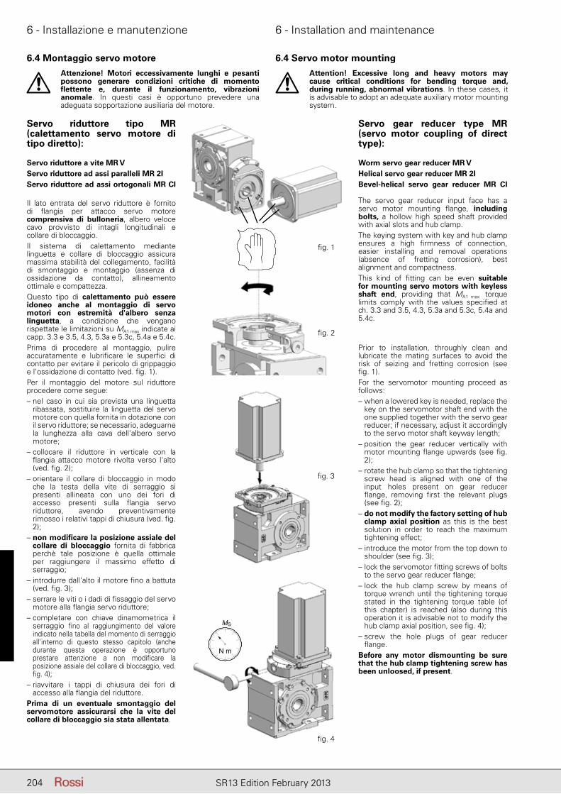
6 - Installazione e manutenzione 6 - Installation and maintenance
204 SR13 Edition February 2013
6.4 Montaggio servo motore
Attenzione! Motori eccessivamente lunghi e pesanti possono generare condizioni critiche di momento flettente e, durante il funzionamento, vibrazioni anomale. In questi casi è opportuno prevedere una adeguata sopportazione ausiliaria del motore.
Servo riduttore tipo MR(calettamento servo motore di tipo diretto):
Servo riduttore a vite MR VServo riduttore ad assi paralleli MR 2IServo riduttore ad assi ortogonali MR CI
Il lato entrata del servo riduttore è fornito di flangia per attacco servo motore comprensiva di bulloneria, albero veloce cavo provvisto di intagli longitudinali e collare di bloccaggio.Il sistema di calettamento mediante linguetta e collare di bloccaggio assicura massima stabilità del collegamento, facilità di smontaggio e montaggio (assenza di ossidazione da contatto), allineamento ottimale e compattezza.Questo tipo di calettamento può essere idoneo anche al montaggio di servo motori con estremità d'albero senza linguetta, a condizione che vengano rispettate le limitazioni su MA1 max indicate ai capp. 3.3 e 3.5, 4.3, 5.3a e 5.3c, 5.4a e 5.4c.Prima di procedere al montaggio, pulire accuratamente e lubrificare le superfici di contatto per evitare il pericolo di grippaggio e l'ossidazione di contatto (ved. fig. 1).Per il montaggio del motore sul riduttore procedere come segue: – nel caso in cui sia prevista una linguetta
ribassata, sostituire la linguetta del servo motore con quella fornita in dotazione con il servo riduttore; se necessario, adeguarne la lunghezza alla cava dell'albero servo motore;
– collocare il riduttore in verticale con la flangia attacco motore rivolta verso l'alto (ved. fig. 2);
– orientare il collare di bloccaggio in modo che la testa della vite di serraggio si presenti allineata con uno dei fori di accesso presenti sulla flangia servo riduttore, avendo preventivamente rimosso i relativi tappi di chiusura (ved. fig. 2);
– non modificare la posizione assiale del collare di bloccaggio fornita di fabbrica perchè tale posizione è quella ottimale per raggiungere il massimo effetto di serraggio;
– introdurre dall'alto il motore fino a battuta (ved. fig. 3);
– serrare le viti o i dadi di fissaggio del servo motore alla flangia servo riduttore;
– completare con chiave dinamometrica il serraggio fino al raggiungimento del valore indicato nella tabella del momento di serraggio all'interno di questo stesso capitolo (anche durante questa operazione è opportuno prestare attenzione a non modificare la posizione assiale del collare di bloccaggio, ved. fig. 4);
– riavvitare i tappi di chiusura dei fori di accesso alla flangia del riduttore.
Prima di un eventuale smontaggio del servomotore assicurarsi che la vite del collare di bloccaggio sia stata allentata.
6.4 Servo motor mounting
Attention! Excessive long and heavy motors may cause critical conditions for bending torque and, during running, abnormal vibrations. In these cases, it is advisable to adopt an adequate auxiliary motor mounting system.
Servo gear reducer type MR(servo motor coupling of direct type):
Worm servo gear reducer MR VHelical servo gear reducer MR 2IBevel-helical servo gear reducer MR CI
The servo gear reducer input face has a servo motor mounting flange, including bolts, a hollow high speed shaft provided with axial slots and hub clamp.The keying system with key and hub clamp ensures a high firmness of connection, easier installing and removal operations (absence of fretting corrosion), best alignment and compactness.This kind of fitting can be even suitable for mounting servo motors with keyless shaft end, providing that MA1 max torque limits comply with the values specified at ch. 3.3 and 3.5, 4.3, 5.3a and 5.3c, 5.4a and 5.4c.
Prior to installation, throughly clean and lubricate the mating surfaces to avoid the risk of seizing and fretting corrosion (see fig. 1).For the servomotor mounting proceed as follows: – when a lowered key is needed, replace the
key on the servomotor shaft end with the one supplied together with the servo gear reducer; if necessary, adjust it accordingly to the servo motor shaft keyway length;
– position the gear reducer vertically with motor mounting flange upwards (see fig. 2);
– rotate the hub clamp so that the tightening screw head is aligned with one of the input holes present on gear reducer flange, removing first the relevant plugs (see fig. 2);
– do not modify the factory setting of hub clamp axial position as this is the best solution in order to reach the maximum tightening effect;
– introduce the motor from the top down to shoulder (see fig. 3);
– lock the servomotor fitting screws of bolts to the servo gear reducer flange;
– lock the hub clamp screw by means of torque wrench until the tightening torque stated in the tightening torque table (of this chapter) is reached (also during this operation it is advisable not to modify the hub clamp axial position, see fig. 4);
– screw the hole plugs of gear reducer flange.
Before any motor dismounting be sure that the hub clamp tightening screw has been unloosed, if present.
fi g. 1
fi g. 2
fi g. 3
fi g. 4
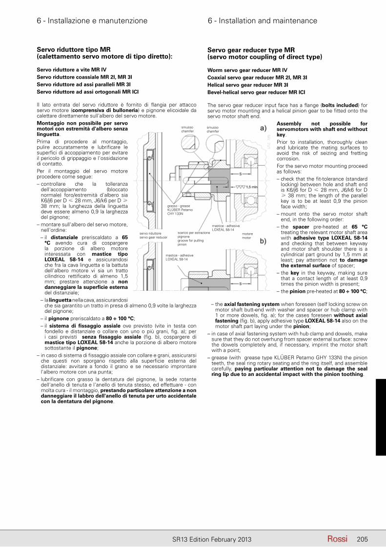
6 - Installazione e manutenzione 6 - Installation and maintenance
205SR13 Edition February 2013
6.4 Montaggio servo motore
Servo riduttore tipo MR(calettamento servo motore di tipo diretto):
Servo riduttore a vite MR IVServo riduttore coassiale MR 2I, MR 3IServo riduttore ad assi paralleli MR 3IServo riduttore ad assi ortogonali MR ICI
Il lato entrata del servo riduttore è fornito di flangia per attacco servo motore (comprensiva di bulloneria) e pignone elicoidale da calettare direttamente sull'albero del servo motore.Montaggio non possibile per servo motori con estremità d'albero senza linguetta.Prima di procedere al montaggio, pulire accuratamente e lubrificare le superfici di accoppiamento per evitare il pericolo di grippaggio e l'ossidazione di contatto.Per il montaggio del servo motore procedere come segue:– controllare che la tolleranza
dell'accoppiamento (bloccato normale) foro/estremità d'albero sia K6/j6 per D ≤ 28 mm, J6/k6 per D ≥ 38 mm; la lunghezza della linguetta deve essere almeno 0,9 la larghezza del pignone;
– montare sull'albero del servo motore, nell'ordine:– il distanziale preriscaldato a 65
°C avendo cura di cospargere la porzione di albero motore interessata con mastice tipo LOXEAL 58-14 e assicurandosi che fra la cava linguetta e la battuta dell'albero motore vi sia un tratto cilindrico rettificato di almeno 1,5 mm; prestare attenzione a non danneggiare la superficie esterna del distanziale;
– la linguetta nella cava, assicurandosi che sia garantito un tratto in presa di almeno 0,9 volte la larghezza del pignone;
– il pignone preriscaldato a 80 ÷ 100 °C;– il sistema di fissaggio assiale ove previsto (vite in testa con
fondello e distanziale o collare con uno o più grani, fig. a); per i casi previsti senza fissaggio assiale (fig. b), cospargere di mastice tipo LOXEAL 58-14 anche la porzione di albero motore sottostante il pignone;
– in caso di sistema di fissaggio assiale con collare e grani, assicurarsi che questi non sporgano rispetto alla superficie esterna del distanziale: avvitare a fondo il grano e se necessario improntare l'albero motore con una punta;
– lubrificare con grasso la dentatura del pignone, la sede rotante dell'anello di tenuta e l'anello di tenuta stesso, ed effettuare - con molta cura - il montaggio, prestando particolare attenzione a non danneggiare il labbro dell'anello di tenuta per urto accidentale con la dentatura del pignone.
6.4 Servo motor mounting
Servo gear reducer type MR(servo motor coupling of direct type)
Worm servo gear reducer MR IVCoaxial servo gear reducer MR 2I, MR 3IHelical servo gear reducer MR 3IBevel-helical servo gear reducer MR ICI
The servo gear reducer input face has a flange (bolts included) for servo motor mounting and a helical pinion gear to be fitted onto the servo motor shaft end.
Assembly not possible for servomotors with shaft end without key.Prior to installation, thoroughly clean and lubricate the mating surfaces to avoid the risk of seizing and fretting corrosion.For the servo motor mounting proceed as follows:– check that the fit-tolerance (standard
locking) between hole and shaft end is K6/j6 for D ≤ 28 mm, J6/k6 for D ≥ 38 mm; the length of the parallel key is to be at least 0,9 the pinion face width;
– mount onto the servo motor shaft end, in the following order:
– the spacer pre-heated at 65 °C treating the relevant motor shaft area with adhesive type LOXEAL 58-14 and checking that between keyway and motor shaft shoulder there is a cylindrical part ground by 1,5 mm at least; pay attention not to damage the external surface of spacer;
– the key in the keyway, making sure that a contact length of at least 0,9 times the pinion width is present;
– the pinion pre-heated at 80 ÷ 100 °C;
– the axial fastening system when foreseen (self locking screw on motor shaft butt-end with washer and spacer or hub clamp with 1 or more dowels, fig. a); for the cases foreseen without axial fastening (fig. b), apply adhesive type LOXEAL 58-14 also on the motor shaft part laying under the pinion;
– in case of axial fastening system with hub clamp and dowels, make sure that they do not overhung from spacer external surface: screw the dowels completely and, if necessary, imprint the motor shaft with a point;
– grease (with grease type KLÜBER Petamo GHY 133N) the pinion teeth, the seal ring rotary seating and the ring itself, and assemble carefully, paying particular attention not to damage the seal ring lip due to an accidental impact with the pinion toothing.
smussochamfer
smussochamfer
grasso - greaseKLÜBER PetamoCHY 133N
mastice - adhesiveLOXEAL 58-14
mastice - adhesiveLOXEAL 58-14
scarico per estrazione pignonegroove for pulling pinion
servo riduttore servo gear reducer
motore motor
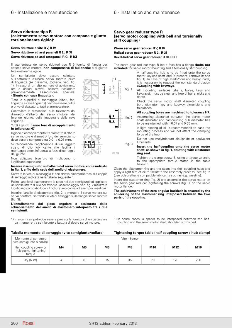
6 - Installazione e manutenzione 6 - Installation and maintenance
206 SR13 Edition February 2013
6.4 Montaggio servo motore
Servo riduttore tipo R(calettamento servo motore con campana e giunto torsionalmente rigido):
Servo riduttore a vite R V, R IVServo riduttore ad assi paralleli R 2I, R 3IServo riduttore ad assi ortogonali R CI, R ICI
Il lato entrata dei servo riduttori tipo R è fornito di flangia per attacco servo motore (non comprensiva di bulloneria) e di giunto torsionalmente rigido.Un semigiunto deve essere calettato sull'estremità d'albero servo motore privo di linguetta (se presente, toglierla, ved. fig. 1). In caso di un alto numero di avviamenti/ora e carichi elevati, occorre richiedere preventivamente l'esecuzione speciale: «Giunto con cava linguetta».Tutte le superfici di montaggio (alberi, fori, linguette e cave linguetta) devono essere pulite e prive di sbavature, tagli e ammaccature.Controllare le dimensioni e le tolleranze del diametro d'albero del servo motore, del foro del giunto, della linguetta e della cava linguetta.Tutti i giunti hanno foro di accoppiamento in tolleranza H7.Il gioco d'accoppiamento tra diametro d'albero servo motore e diametro foro del semigiunto deve essere compreso tra 0,01 e 0,05 mm.Si raccomanda l'applicazione di un leggero strato di olio lubrificante che facilita il montaggio e non influenza la forza di serraggio del giunto.Non utilizzare bisolfuro di molibdeno o lubrificanti equivalenti.Inserire il semigiunto sull'albero del servo motore, come indicato in fig. 1, a filo della sede dell'anello di elastomero. Serrrare la vite di bloccaggio E con chiave dinamometrica alla coppia di serraggio indicata nella tabella seguente 1).Pulire l'anello di elastomero e la sede nei due semigiunti ed applicare un sottile strato di olio per favorire l'assemblaggio, ved. fig. 2 (utilizzare lubrificanti compatibili con il poliuretano come ad esempio vaselina).Inserire l'anello di elastomero (fig. 2) e montare il servo motore sul servo riduttore, serrando le viti di fissaggio sulla flangia servo motore (fig. 3).L'annullamento del gioco angolare è assicurato dallo schiacciamento dell'anello di elastomero interposto tra i due semigiunti.
1) In alcuni casi potrebbe essere prevista la fornitura di un distanziale da interporre tra semigiunto e battuta d'albero servo motore.
6.4 Servo motor mounting
Servo gear reducer type R(servo motor coupling with bell and torsionally stiff coupling)
Worm servo gear reducer R V, R IVHelical servo gear reducer R 2I, R 3IBevel-helical servo gear reducer R CI, R ICI
The servo gear reducer type R input face has a flange (bolts not included) for servo motor mounting and a torsionally stiff coupling.
A half-coupling hub is to be fitted onto the servo motor keyless shaft end (if present, remove it; see fig. 1). In case of high starts/hour and heavy loads, it is necessary to request the non-standard design «Coupling with keyway».All mounting surfaces (shafts, bores, keys and keyways), must be clean and free of burrs, nicks and dents.Check the servo motor shaft diameter, coupling bore diameter, key and keyway dimensions and tolerances.All coupling bores are machined to tolerance H7.Assembling clearance between the servo motor shaft diameter and half-coupling hub diameter has to be maintained within 0,01 and 0,05 mm.A light coating of oil is recommended to ease the mounting process and will not affect the clamping force of the hub.Do not use molybdenum disulphide or equivalent lubricants.Insert the half-coupling onto the servo motor shaft, as shown in fig. 1, abutting with elastomer ring seat. Tighten the clamp screw E, using a torque wrench, to the appropriate torque stated in the table below 1).
Clean the elastomer ring and the seats into the coupling hubs and apply a light film of oil to facilitate the assembly process, see fig. 2 (use polyurethane compatible lubricants such as e.g. vaseline). Insert the elastomer ring (fig. 2) and assemble the servo motor on the servo gear reducer, tightening the screws (fig. 3) on the servo motor flange.The achievement of the zero angular backlash is ensured by the squeezing of the elastomer ring interposed between the two parts of the coupling.
1) In some cases, a spacer to be interposed between the half-coupling and the servo motor shaft shoulder is provided
Momento di serraggio vite semigiunto o collare
Vite - Screw
Half coupling screw or hub clamp tightening
torque
M4 M5 M6 M8 M10 M12 M16
MS [N m] 4 8 15 35 70 120 290
fi g. 1
fi g. 2
fi g. 3
Tabella momento di serraggio (vite semigiunto/collare) Tightening torque table (half coupling screw / hub clamp)

207SR13 Edition February 2013
Pagina lasciata intenzionalmente biancaThis page is intentionally left blank

6 - Installazione e manutenzione 6 - Installation and maintenance
208 SR13 Edition February 2013
6.5 Montaggio di organi sull'estremità d'alberoPer il foro degli organi calettati sull'estremità d'albero si raccomanda la tolleranza J7 o K7; larghezza cava linguetta in tolleranza H8 o J8. Altri dati secondo tabelle Estremità d'albero (capp. 3.9, 4.6 e 5.8).Prima di procedere al montaggio pulire bene e lubrifi care le superfi ci di contatto per evitare il pericolo di grippaggio e l'ossidazione di contatto. Il montaggio e lo smontaggio si effettuano con l'ausilio di tiranti ed estrattori servendosi dei fori fi lettati in testa all'estremità d'albero; per accoppiamenti, K7/j6 e K7/k6 è consigliabile effettuare il montaggio a caldo riscaldando l'organo da calettare a 80 ÷ 100 °C.
6.5 Fitting of components to shaft endsIt is recommended that the holes of parts keyed onto shaft ends should be machined to J7 or K7 tolerance; keyway width in tolerance H8 or J8. Other data to the tables (ch. 3.9, 4.6 and 5.8).Before mounting, thoroughly clean mating surfaces and lubricate against seizure and fretting corrosion. Installing and removal operations should be carried out with the aid of jacking screws and pullers using the tapped hole at the shaft butt-end; for couplings, K7/j6 and K7/k6 it is advisable that the part to be keyed is preheated to a temperature of 80 ÷ 100 °C.
Albero cavoPer il perno delle macchine sul quale va calettato l'albero cavo del riduttore, raccomandiamo le tolleranze j6 oppure k6 secondo le esigenze; per la tolleranza larghezza linguetta h8, cava labero N8. Altri dati secondo quanto indicato al paragrafo «Estremità d'albero» e «Perno macchina» (capp. 3.9 e 5.7).Per facilitare il montaggio e lo smontaggio dei servo riduttori ad albero lento cavo con gola anello elastico, procedere come raffigurato nelle figg. a, b rispettivamente.Per R e MR 3I 64 ... 81, prima inserire nell'abero cavo del riduttore (dal lato opposto motore) la rosetta munita di vite e l'anello elastico, quindi montare sul perno macchina.Per il fissaggio assiale si può adottare il sistema raffigurato nelle figg. c, d.Per grandezze ≥ 64 (63 per riduttori a vite), quando il perno macchina è senza battuta, si può interporre un distanziale tra l'anello elastico e il perno stesso (metà inferiore della figura d).Utilizzando gli anelli di bloccaggio (fig. e), o la bussola di bloccaggio (fig. f) è possibile conseguire un montaggio e uno smontaggio più facili e precisi e l'eliminazione del gioco tra linguetta e relativa cava.Gli anelli o la bussola di bloccaggio devono essere inseriti dopo il montaggio (per MR 3I 64 ... 81 inserire la bussola sul perno macchina o nell'albero cavo prima del montaggio; fare attenzione ad orientare la cava linguetta) e dopo avere accuratamente sgrassato le superfici; il perno macchina deve essere come indicato ai capp. 3.9, 5.7 (5.8 nel caso di albero lento cavo differenziato, con unità di bloccaggio).Non utilizzare bisolfuro di molibdeno o lubrificanti equivalenti per la lubrificazione delle superfici a contatto.Per il montaggio della vite si raccomanda l'impiego di adesivi bloccanti tipo LOCTITE 601.Per montaggi verticali a soffitto interpellarci.In caso di fissaggio assiale con anelli o bussola di bloccaggio - soprattutto in presenza di cicli gravosi di lavoro, con frequenti inversioni del moto - verificare, dopo alcune ore di funzionamento, il momento di serraggio della vite ed eventualmente riapplicare l'adesivo bloccante.A richiesta si può fornire la rosetta di montaggio, smontaggio e fissaggio assiale riduttore con o senza gli anelli o la bussola di bloccaggio (dimensioni indicate in tabella) o l'albero lento cavo con unità di bloccaggio (dimensioni indicate ai capp. 3.9 e 5.8) e il cappellotto di protezione albero lento cavo.Le parti a contatto con l'eventuale anello elastico devono essere a spigolo vivo.Se vi sono pericoli per persone o cose derivanti da cadute o proiezioni del riduttore o di parti di esso, prevedere appropriate sicurezze contro: - la rotazione o lo sfilamento del riduttore dal perno macchina conseguenti a rotture accidentali del vincolo di reazione.
Hollow shaftFor machine shaft end onto which the hollow shaft of gear reducer is to be keyed, j6 or k6 tolerances are recommended, according to requirements; for key width tolerance h8, shaft keyway N8. For further data see paragraph «Shaft end» and «Machine shaft end» (ch. 3.9 and 5.7).When assembling and disassembling the servo gear boxes with hollow low speed shaft with circlip groove, proceed as per fig. a, b, respectively.For R and MR 3I 64 ... 81 first insert the washer with screw and the circlip into gear reducer hollow shaft (on motor opposite side); then mount on machine shaft end.For axial fastening the system illustrated in the fig. c, d may be adopted.For sizes ≥ 64 (63 for worm gear reducers), when shaft end of driven machine has no shoulder a spacer may be located between the circlip and the shaft end itself (as in the lower half of the fig. d).The use of locking rings (fig. e), or of locking bush (fig. f) will permit easier and more accurate installing and removing and to eliminate backlash between key and keyway.The locking rings or the locking bush are fitted after mounting (for MR 3I 64 ... 81 insert the bush onto machine shaft end or into hollow shaft before mounting; pay attention when positioning the keyway) and after having fully degreased the coupling surfaces; the shaft end of the driven machine must be as prescribed at ch. 3.9, 5.7 (5.8 in case of hollow low speed shaft: stepped, with shrink disc). Do not use molybdenum disulphide or equivalent lubricant for the lubrication of the parts in contact.When tightening the bolt, we recommend the use of a locking adhesive such as LOCTITE 601.For vertical ceiling-type mounting, contact us.In case of axial fastening with locking rings or bush - especially when having heavy duty cycles, with frequent reversals - verify, after some hours of running, the bolt tightening torque and, if necessary, apply the locking adhesive again.On request a washer for installing, removing and axial fastening of gear reducer with or without locking rings, locking bush (dimensions shown in the table) or hollow low speed shaft with shrink disc (dimensions stated on ch. 3.9, 5.8), and a protection cap for the hollow low speed shaft can be supplied on request.Parts in contact with the circlip must have sharp edges.Whenever personal injury or property damage may occur, foresee adequate supplementary protection devices against: - rotation or unthreading of the gear reducer from shaft end of driven machine following to accidental breakage of the reaction arrangement; - accidental breakage of shaft end of driven machine.
Smontaggio albero lento cavo servoriduttori paralleli, ortogonali e vite
Per lo smontaggio dell’albero lento cavo (è la prima operazione da eseguire per smontare il riduttore) orientare la cava linguetta verso l’asse intermedio co me indicato nella figura a fianco e spingere l’albero sul lato gola di riferimento per servoriduttori paralleli e ortogonali (ved. cap. 5.7).Per il perno delle macchine sul quale va calettato l’albero cavo del riduttore, raccomandiamo le tolle-ranze h6, j6 oppure k6 secondo le esigenze. Altri dati se condo quanto indicato al paragrafo «Estremità d’al-bero» e «Perno macchina» (cap. 3.9 e 5.7).
Hollow low speed shaft parallel, right angle shaft and worm servo gear reducers
In order to remove the hollow low speed shaft (this is the first operation to perform when disassembling the gear reducer) turn the shaft until the keyway is facing the intermediate shaft, as shown in the drawing alongside, and push the shaft from the reference groove side for parallel and right angle shaft servo gear reducers (see ch. 5.7).For the shaft end of machines where the hollow shaft of the gear reducer is to be keyed, h6, j6 or k6 toler-ances are recommended (according to requirements). Other details are given under «Shaft end» and «Shaft
end of driven machine» (ch. 3.9 and 5.7).
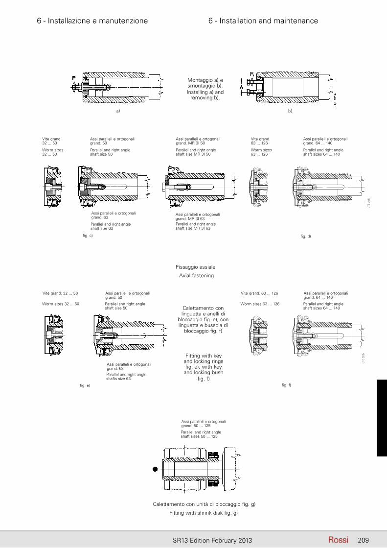
6 - Installazione e manutenzione 6 - Installation and maintenance
209SR13 Edition February 2013
Axial fastening
Fitting with keyand locking ringsfig. e), with key
and locking bushfig. f)
Fitting with shrink disk fig. g)
fig. c)
fig. e)
Worm sizes32 ... 50
Parallel and right angle shaft size 50
Worm sizes 32 ... 50 Parallel and right angle shaft size 50
Parallel and right angle shafts size 63
Parallel and right angle shaft sizes 50 ... 125
Parallel and right angle shaft size 63
Worm sizes63 ... 126
Parallel and right angle shaft sizes 64 ... 140
Worm sizes 63 ... 126 Parallel and right angle shaft sizes 64 ... 140
fig. d)
fig. f)
Parallel and right angle shaft size MR 3I 50
Parallel and right angle shaft size MR 3I 63
Vite grand.32 ... 50
Assi paralleli e ortogonali grand. 50
Vite grand.63 ... 126
Assi paralleli e ortogonali grand. 64 ... 140
Assi paralleli e ortogonali grand. MR 3I 50
Fissaggio assiale
Assi paralleli e ortogonali grand. 63
Assi paralleli e ortogonali grand. MR 3I 63
Vite grand. 32 ... 50 Assi paralleli e ortogonali grand. 50
Vite grand. 63 ... 126 Assi paralleli e ortogonali grand. 64 ... 140
Calettamento con linguetta e anelli di
bloccaggio fig. e), con linguetta e bussola di
bloccaggio fig. f)
Assi paralleli e ortogonali grand. 63
Assi paralleli e ortogonali grand. 50 ... 125
Calettamento con unità di bloccaggio fig. g)
Montaggio a) esmontaggio b).Installing a) and
removing b).
a) b)
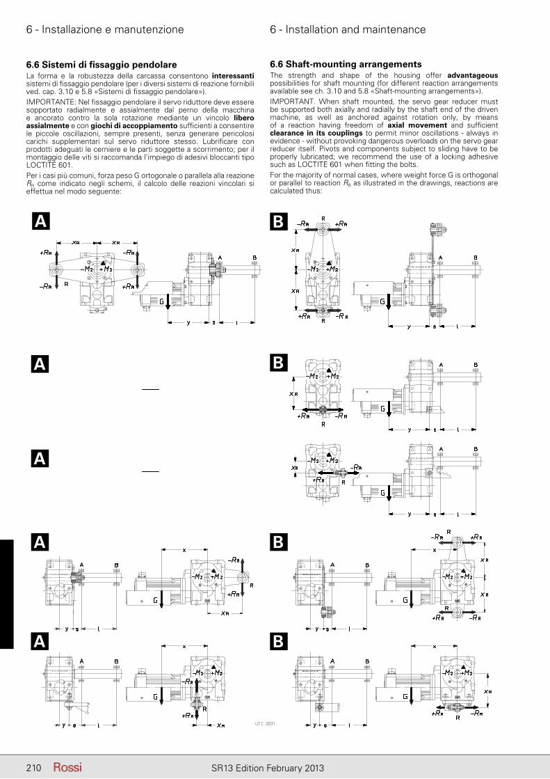
6 - Installazione e manutenzione 6 - Installation and maintenance
210 SR13 Edition February 2013
6.6 Sistemi di fi ssaggio pendolareLa forma e la robustezza della carcassa consentono interessanti sistemi di fi ssaggio pendolare (per i diversi sistemi di reazione fornibili ved. cap. 3.10 e 5.8 «Sistemi di fi ssaggio pendolare»).IMPORTANTE: Nel fi ssaggio pendolare il servo riduttore deve essere sopportato radialmente e assialmente dal perno della macchina e ancorato contro la sola rotazione mediante un vincolo libero assialmente e con giochi di accoppiamento suffi cienti a consentire le piccole oscillazioni, sempre presenti, senza generare pericolosi carichi supplementari sul servo riduttore stesso. Lubrifi care con prodotti adeguati le cerniere e le parti soggette a scorrimento; per il montaggio delle viti si raccomanda l'impiego di adesivi bloccanti tipo LOCTITE 601.Per i casi più comuni, forza peso G ortogonale o parallela alla reazione RR come indicato negli schemi, il calcolo delle reazioni vincolari si effettua nel modo seguente:
6.6 Shaft-mounting arrangementsThe strength and shape of the housing offer advantageous possibilities for shaft mounting (for different reaction arrangements available see ch. 3.10 and 5.8 «Shaft-mounting arrangements»).IMPORTANT. When shaft mounted, the servo gear reducer must be supported both axially and radially by the shaft end of the driven machine, as well as anchored against rotation only, by means of a reaction having freedom of axial movement and suffi cient clearance in its couplings to permit minor oscillations - always in evidence - without provoking dangerous overloads on the servo gear reducer itself. Pivots and components subject to sliding have to be properly lubricated; we recommend the use of a locking adhesive such as LOCTITE 601 when fi tting the bolts.For the majority of normal cases, where weight force G is orthogonal or parallel to reaction RR as illustrated in the drawings, reactions are calculated thus:
A B
A
A
B
A
A
B
B
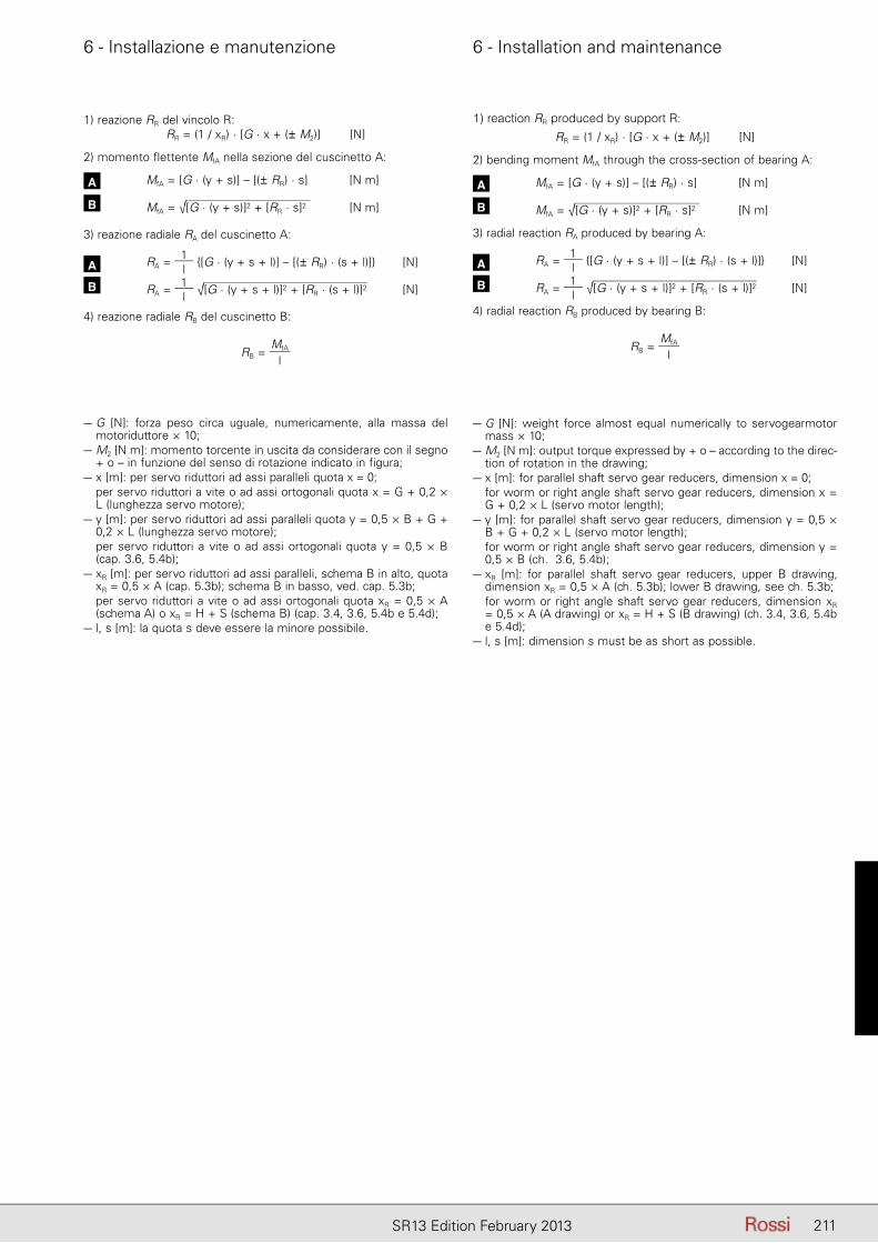
6 - Installazione e manutenzione 6 - Installation and maintenance
211SR13 Edition February 2013
1) reaction RR produced by support R:
RR = (1 / xR) · [G · x + (± M2)] [N]
2) bending moment MfA through the cross-section of bearing A:
A MfA = [G · (y + s)] – [(± RR) · s] [N m]
B MfA = √[G · (y + s)]2 + [RR · s]2 [N m]
3) radial reaction RA produced by bearing A:
A RA = 1l
{[G · (y + s + l)] – [(± RR) · (s + l)]} [N]
B RA = 1l
√[G · (y + s + l)]2 + [RR · (s + l)]2 [N]
4) radial reaction RB produced by bearing B:
RB = MfA
l
1) reazione RR del vincolo R:RR = (1 / xR) · [G · x + (± M2)] [N]
2) momento flettente MfA nella sezione del cuscinetto A:
A MfA = [G · (y + s)] – [(± RR) · s] [N m]
B MfA = √[G · (y + s)]2 + [RR · s]2 [N m]
3) reazione radiale RA del cuscinetto A:
A RA = 1l
{[G · (y + s + l)] – [(± RR) · (s + l)]} [N]
B RA = 1l
√[G · (y + s + l)]2 + [RR · (s + l)]2 [N]
4) reazione radiale RB del cuscinetto B:
RB = MfA
l
– G [N]: forza peso circa uguale, numericamente, alla massa del motoriduttore × 10;
– M2 [N m]: momento torcente in uscita da considerare con il se gno + o – in funzione del senso di rotazione indicato in figura;
– x [m]: per servo riduttori ad assi paralleli quota x = 0;– per servo riduttori a vite o ad assi ortogonali quota x = G + 0,2 ×
L (lunghezza servo motore);– y [m]: per servo riduttori ad assi paralleli quota y = 0,5 × B + G +
0,2 × L (lunghezza servo motore);– per servo riduttori a vite o ad assi ortogonali quota y = 0,5 × B
(cap. 3.6, 5.4b);– xR [m]: per servo riduttori ad assi paralleli, schema B in alto, quota
xR = 0,5 × A (cap. 5.3b); schema B in basso, ved. cap. 5.3b;– per servo riduttori a vite o ad assi ortogonali quota xR = 0,5 × A
(schema A) o xR = H + S (schema B) (cap. 3.4, 3.6, 5.4b e 5.4d);– l, s [m]: la quota s deve essere la minore possibile.
– G [N]: weight force almost equal numerically to servogearmotor mass × 10;
– M2 [N m]: output torque expressed by + o – according to the direc-tion of rotation in the drawing;
– x [m]: for parallel shaft servo gear reducers, dimension x = 0;– for worm or right angle shaft servo gear reducers, dimension x =
G + 0,2 × L (servo motor length);– y [m]: for parallel shaft servo gear reducers, dimension y = 0,5 ×
B + G + 0,2 × L (servo motor length);– for worm or right angle shaft servo gear reducers, dimension y =
0,5 × B (ch. 3.6, 5.4b);– xR [m]: for parallel shaft servo gear reducers, upper B drawing,
dimension xR = 0,5 × A (ch. 5.3b); lower B drawing, see ch. 5.3b;– for worm or right angle shaft servo gear reducers, dimension xR
= 0,5 × A (A drawing) or xR = H + S (B drawing) (ch. 3.4, 3.6, 5.4b e 5.4d);
– l, s [m]: dimension s must be as short as possible.
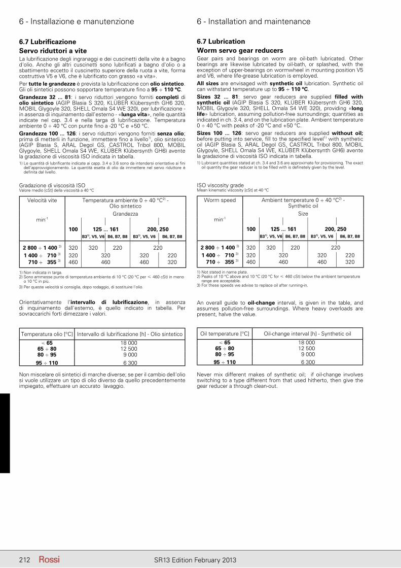
6 - Installazione e manutenzione 6 - Installation and maintenance
212 SR13 Edition February 2013
6.7 Lubrifi cazioneServo riduttori a viteLa lubrifi cazione degli ingranaggi e dei cuscinetti della vite è a bagno d'olio. Anche gli altri cuscinetti sono lubrifi cati a bagno d'olio o a sbattimento eccetto il cuscinetto superiore della ruota a vite, forma costruttiva V5 e V6, che è lubrifi cato con grasso «a vita».Per tutte le grandezze è prevista la lubrifi cazione con olio sintetico. Gli oli sintetici possono sopportare temperature fi no a 95 ÷ 110 °C.Grandezze 32 ... 81: i servo riduttori vengono forniti completi di olio sintetico (AGIP Blasia S 320, KLÜBER Klübersynth GH6 320, MOBIL Glygoyle 320, SHELL Omala S4 WE 320), per lubrifi cazione - in assenza di inquinamento dall'esterno - «lunga vita», nelle quantità indicate nel cap. 3.4 e nella targa di lubrifi cazione. Temperatura ambiente 0 ÷ 40 °C con punte fi no a -20 °C e +50 °C.Grandezze 100 ... 126: i servo riduttori vengono forniti senza olio; prima di metterli in funzione, immettere fi no a livello1), olio sintetico (AGIP Blasia S, ARAL Degol GS, CASTROL Tribol 800, MOBIL Glygoyle, SHELL Omala S4 WE, KLÜBER Klübersynth GH6) avente la gradazione di viscosità ISO indicata in tabella.1) Le quantità di lubrifi cante indicate ai capp. 3.4 e 3.6 sono da intendersi orientative ai fi ni
dell'approvvigionamento. La quantità esatta di olio da immettere nel servo riduttore è defi nita dal livello.
6.7 LubricationWorm servo gear reducersGear pairs and bearings on worm are oil-bath lubricated. Other bearings are likewise lubricated by oil-bath, or splashed, with the exception of upper-bearings on wormwheel in mounting position V5 and V6, where life-grease lubrication is employed.All sizes are envisaged with synthetic oil lubrication. Synthetic oil can withstand temperature up to 95 ÷ 110 °C.Sizes 32 ... 81: servo gear reducers are supplied fi lled with synthetic oil (AGIP Blasia S 320, KLÜBER Klübersynth GH6 320, MOBIL Glygoyle 320, SHELL Omala S4 WE 320), providing «long life» lubrication, assuming pollution-free surroundings; quantities as indicated in ch. 3.4, and on the lubrication plate. Ambient temperature 0 ÷ 40 °C with peaks of -20 °C and +50 °C.Sizes 100 ... 126: servo gear reducers are supplied without oil; before putting into service, fi ll to the specifi ed level1) with synthetic oil (AGIP Blasia S, ARAL Degol GS, CASTROL Tribol 800, MOBIL Glygoyle, SHELL Omala S4 WE, KLÜBER Klübersynth GH6) avente la gradazione di viscosità ISO indicata in tabella.1) Lubricant quantities stated at ch. 3.4 and 3.6 are approximate for provisioning. The exact
oil quantity the gear reducer is to be fi lled with is defi netely given by the level.
Gradazione di viscosità ISOValore medio [cSt] della viscosità a 40 °C
ISO viscosity gradeMean kinematic viscosity [cSt] at 40 °C
1) Non indicata in targa.2) Sono ammesse punte di temperatura ambiente di 10 °C (20 °C per ≤ 460 cSt) in meno
o 10 °C in più.3) Per queste velocità si consiglia, dopo rodaggio, di sostituire l'olio.
1) Not stated in name plate.2) Peaks of 10 °C above and 10 °C (20 °C for ≤ 460 cSt) below the ambient temperature
range are acceptable.3) For these speeds we advise to replace oil after running-in.
Orientativamente l'intervallo di lubrifi cazione, in assenza di inquinamento dall'esterno, è quello indicato in tabella. Per sovraccarichi forti dimezzare i valori.
An overall guide to oil-change interval, is given in the table, and assumes pollution-free surroundings. Where heavy overloads are present, halve the value.
Temperatura olio [°C] Intervallo di lubrifi cazione [h] - Olio sintetico
≤ 65 18 00065 ÷ 80 12 50080 ÷ 95 9 000
95 ÷ 110 6 300
Oil temperature [°C] Oil-change interval [h] - Synthetic oil
≤ 65 18 00065 ÷ 80 12 50080 ÷ 95 9 000
95 ÷ 110 6 300
Non miscelare oli sintetici di marche diverse; se per il cambio dell'olio si vuole utilizzare un tipo di olio diverso da quello precedentemente impiegato, effettuare un accurato lavaggio.
Never mix different makes of synthetic oil; if oil-change involves switching to a type different from that used hitherto, then give the gear reducer a through clean-out.
Velocità vite Temperatura ambiente 0 ÷ 40 °C2) - Olio sintetico
Grandezza min-1
100 125 ... 161 200, 250B31), V5, V6 B6, B7, B8 B31), V5, V6 B6, B7, B8
2 800 ÷ 1 400 3) 320 320 220 2201 400 ÷ 710 3) 320 320 320 220 710 ÷ 355 3) 460 460 460 320
Worm speed Ambient temperature 0 ÷ 40 °C2) - Synthetic oil
Size min-1
100 125 ... 161 200, 250B31), V5, V6 B6, B7, B8 B31), V5, V6 B6, B7, B8
2 800 ÷ 1 400 3) 320 320 220 2201 400 ÷ 710 3) 320 320 320 220 710 ÷ 355 3) 460 460 460 320
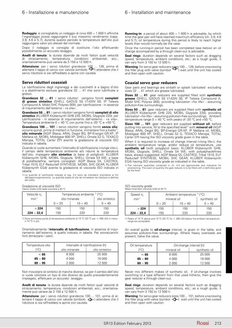
6 - Installazione e manutenzione 6 - Installation and maintenance
213SR13 Edition February 2013
Rodaggio: è consigliabile un rodaggio di circa 400 ÷ 1 600 h affi nché l'ingranaggio possa raggiungere il suo massimo rendimento (capp. 3.9, 4.6 e 5.7); durante questo periodo la temperatura dell'olio può raggiungere valori più elevati del normale.Dopo il rodaggio si consiglia di sostituire l'olio effettuando possibilmente un accurato lavaggio.Anelli di tenuta: la durata dipende da molti fattori quali velocità di strisciamento, temperatura, condizioni ambientali, ecc.; orientativamente può variare da 3 150 a 12 500 h.Attenzione: per i servo riduttori grandezze 100 ... 126, prima di allentare il tappo di carico con valvola (simbolo ) attendere che il servo riduttore si sia raffreddato e aprire con cautela.
Servo riduttori coassialiLa lubrifi cazione degli ingranaggi e dei cuscinetti è a bagno d'olio o a sbattimento escluse grandezze 32 ... 41 che sono lubrifi cate a grasso.Grandezze 32 ... 41: i servo riduttori vengono forniti completi di grasso sintetico (SHELL GADUS S5 V142W 00, IP Telesia Compound A, Mobil SHC Polyrex 005), per lubrifi cazione - in assenza di inquinamento dall'esterno - «a vita».Grandezze 50 ... 81: i servo riduttori vengono forniti completi di olio sintetico (KLÜBER Klübersynth GH6 220, MOBIL Glygoyle 220), per lubrifi cazione - in assenza di inquinamento dall'esterno - «a vita». Temperatura ambiente 0 ÷ 40 °C con punte fi no a -20 °C e +50 °C.Grandezze 100 ... 101: i servo riduttori vengono forniti senza olio; occorre quindi, prima di metterli in funzione, immettere fi no a livello1), olio minerale (AGIP Blasia, ARAL Degol BG, BP-Energol GR-XP, IP Mellana oil, MOBIL Mobilgear 600 XP, SHELL Omala S2 G, TEXACO Meropa, TOTAL Carter EP) avente la gradazione di viscosità ISO indicata in tabella.Quando si vuole aumentare l'intervallo di lubrifi cazione («lunga vita»), il campo della temperatura ambiente e/o ridurre la temperatura dell'olio, impiegare olio sintetico (a base di poliglicoli: KLÜBER Klübersynth GH6, MOBIL Glygoyle, SHELL Omala S4 WE; a base di polialfaolefi ne, sempre consigliati: AGIP Blasia SX, CASTROL Tribal 1510, ELF Reductelf SYNTHESE, MOBIL SHC GEAR, KLÜBER Klübersynth EG4) avente la gradazione di viscosità ISO indicata in tabella.1) Le quantità di lubrifi cante indicate al cap. 4.4 sono da intendersi orientative ai fi ni
dell'approvvigionamento. La quantità esatta di olio da immettere nel riduttore è defi nita dal livello.
Running-in: a period of about 400 ÷ 1 600 h is advisable, by which time the gear pair will have reached maximum effi ciency (ch. 3.9, 4.6 and 5.7); oil temperature during this period is likely to reach higher levels than would normally be the case.Once the running-in period has been completed (see below) an oil change accompanied by a through clean-out is advisable.Seal rings: duration depends on several factors such as dragging speed, temperature, ambient conditions, etc.; as a rough guide, it can vary from 3 150 to 12 500 h.Warning: for servo gear reducers sizes 100 ... 126, before unscrewing the fi ller plug with valve (symbol ) wait until the unit has cooled and then open with caution.
Coaxial servo gear reducersGear pairs and bearings are oil-bath or splash lubricated excluding sizes 32 ... 41 which are grease lubricated.Sizes 32 ... 41: gear reducers are supplied fi lled with synthetic grease (SHELL GADUS S5 V142W 00, IP Telesia Compound A, Mobil SHC Polyrex 005), providing lubrication «for life» - assuming pollution-free surroundings.Sizes 50 ... 81: gear reducers are supplied fi lled with synthetic oil (KLÜBER Klübersynth GH6 220, MOBIL Glygoyle 220), providing lubrication «for life» - assuming pollution-free surroundings. Ambient temperature range 0 ÷ 40 °C with peaks of -20 °C and +50 °C.Sizes 100 ... 101: gear reducers are supplied without oil; before putting into service, fi ll to the specifi ed level1) with mineral oil (AGIP Blasia, ARAL Degol BG, BP-Energol GR-XP, IP Mellana oil, MOBIL Mobilgear 600 XP, SHELL Omala S2 G, TEXACO Meropa, TOTAL Carter EP) having the ISO viscosity grade given in the table.When it is required to increase oil change interval («long life»), the ambient temperature range, and/or reduce oil temperature, use synthetic oil (with polyglycol basis: KLÜBER Klübersynth GH6, MOBIL Glygoyle, SHELL Omala S4 WE; with polyalphaolefi nes basis, always suggested: AGIP Blasia SX, CASTROL Tribal 1510, ELF Reductelf SYNTHESE, MOBIL SHC GEAR, KLÜBER Klübersynth EG4) having ISO viscosity grade as indicated in the table.1) The lubricant quantities contained in ch. 4.4 are approximate and indicative for
provisioning. The exact oil quantity the gear reducer is to be fi lled with is defi nitely given by the level.
Gradazione di viscosità ISOValore medio [cSt] della viscosità a 40 °C
ISO viscosity gradeMean kinematic viscosity [cSt] at 40 °C
Velocità n2 Temperatura ambiente 1) [°C]min-1 olio minerale olio sintetico
0 ÷ 20 10 ÷ 40 0 ÷ 40
> 224 150 150 150224 ÷ 22,4 150 220 220
Speed n2 Ambient temperature 1) [°C]min-1 mineral oil synthetic oil
0 ÷ 20 10 ÷ 40 0 ÷ 40
> 224 150 150 150224 ÷ 22,4 150 220 220
1) Sono ammesse punte di temperatura ambiente di 10 °C (20 °C per ≤ 460 cSt) in meno o 10 °C in più.
1) Peaks of 10 °C above and 10 °C (20 °C for ≤ 460 cSt) below the ambient temperature range are acceptable.
Orientativamente l'intervallo di lubrifi cazione, in assenza di inqui-namento dall'esterno, è quello indicato in tabella. Per sovraccarichi forti dimezzare i valori.
An overall guide to oil-change interval, is given in the table, and assumes pollution-free surroundings. Where heavy overloads are present, halve the value.
Temperatura olio Intervallo di lubrifi cazione [h][°C] olio minerale olio sintetico
� 65 8 000 25 00065 ÷ 80 4 000 18 00080 ÷ 95 2 000 12 500
Oil temperature Oil-change interval [h][°C] mineral oil synthetic oil
� 65 8 000 25 00065 ÷ 80 4 000 18 00080 ÷ 95 2 000 12 500
Non miscelare oli sintetici di marche diverse; se per il cambio dell'olio si vuole utilizzare un tipo di olio diverso da quello precedentemente impiegato, effettuare un accurato lavaggio.
Anelli di tenuta: la durata dipende da molti fattori quali velocità di strisciamento, temperatura, condizioni ambientali, ecc.; orientativa-mente può variare da 3 150 a 12 500 h.Attenzione: per i servo riduttori grandezze 100 ... 101, prima di al-lentare il tappo di carico con valvola (simbolo ) attendere che il riduttore si sia raffreddato e aprire con cautela.
Never mix different makes of synthetic oil; if oil-change involves switching to a type different from that used hitherto, then give the gear reducer a through clean-out.
Seal rings: duration depends on several factors such as dragging speed, temperature, ambient conditions, etc.; as a rough guide, it can vary from 3 150 to 12 500 h.Warning: for servo gear reducers sizes 100 ... 101, before unscrewing the fi ller plug with valve (symbol ) wait until the unit has cooled and then open with caution.
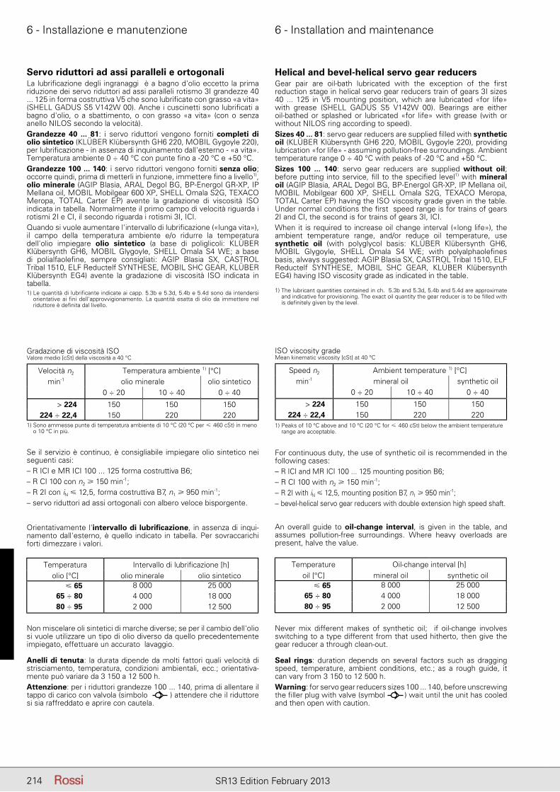
6 - Installazione e manutenzione 6 - Installation and maintenance
214 SR13 Edition February 2013
6.7 Lubrifi cazione
Servo riduttori ad assi paralleli e ortogonaliLa lubrifi cazione degli ingranaggi è a bagno d'olio eccetto la prima riduzione dei servo riduttori ad assi paralleli rotismo 3I grandezze 40 ... 125 in forma costruttiva V5 che sono lubrifi cate con grasso «a vita» (SHELL GADUS S5 V142W 00). Anche i cuscinetti sono lubrifi cati a bagno d'olio, o a sbattimento, o con grasso «a vita» (con o senza anello NILOS secondo la velocità).Grandezze 40 ... 81: i servo riduttori vengono forniti completi di olio sintetico (KLÜBER Klübersynth GH6 220, MOBIL Gygoyle 220), per lubrifi cazione - in assenza di inquinamento dall'esterno - «a vita». Temperatura ambiente 0 ÷ 40 °C con punte fi no a -20 °C e +50 °C.Grandezze 100 ... 140: i servo riduttori vengono forniti senza olio; occorre quindi, prima di metterli in funzione, immettere fi no a livello1), olio minerale (AGIP Blasia, ARAL Degol BG, BP-Energol GR-XP, IP Mellana oil, MOBIL Mobilgear 600 XP, SHELL Omala S2G, TEXACO Meropa, TOTAL Carter EP) avente la gradazione di viscosità ISO indicata in tabella. Normalmente il primo campo di velocità riguarda i rotismi 2I e CI, il secondo riguarda i rotismi 3I, ICI.Quando si vuole aumentare l'intervallo di lubrifi cazione («lunga vita»), il campo della temperatura ambiente e/o ridurre la temperatura dell'olio impiegare olio sintetico (a base di poliglicoli: KLÜBER Klübersynth GH6, MOBIL Glygoyle, SHELL Omala S4 WE; a base di polialfaolefi ne, sempre consigliati: AGIP Blasia SX, CASTROL Tribal 1510, ELF Reductelf SYNTHESE, MOBIL SHC GEAR, KLÜBER Klübersynth EG4) avente la gradazione di viscosità ISO indicata in tabella.1) Le quantità di lubrifi cante indicate ai capp. 5.3b e 5.3d, 5.4b e 5.4d sono da intendersi
orientative ai fi ni dell'approvvigionamento. La quantità esatta di olio da immettere nel riduttore è defi nita dal livello.
6.7 Lubrication
Helical and bevel-helical servo gear reducersGear pair are oil-bath lubricated with the exception of the fi rst reduction stage in helical servo gear reducers train of gears 3I sizes 40 ... 125 in V5 mounting position, which are lubricated «for life» with grease (SHELL GADUS S5 V142W 00). Bearings are either oil-bathed or splashed or lubricated «for life» with grease (with or without NILOS ring according to speed).Sizes 40 ... 81: servo gear reducers are supplied fi lled with synthetic oil (KLÜBER Klübersynth GH6 220, MOBIL Gygoyle 220), providing lubrication «for life» - assuming pollution-free surroundings. Ambient temperature range 0 ÷ 40 °C with peaks of -20 °C and +50 °C.Sizes 100 ... 140: servo gear reducers are supplied without oil; before putting into service, fi ll to the specifi ed level1) with mineral oil (AGIP Blasia, ARAL Degol BG, BP-Energol GR-XP, IP Mellana oil, MOBIL Mobilgear 600 XP, SHELL Omala S2G, TEXACO Meropa, TOTAL Carter EP) having the ISO viscosity grade given in the table. Under normal conditions the fi rst speed range is for trains of gears 2I and CI, the second is for trains of gears 3I, ICI.When it is required to increase oil change interval («long life»), the ambient temperature range, and/or reduce oil temperature, use synthetic oil (with polyglycol basis: KLÜBER Klübersynth GH6, MOBIL Glygoyle, SHELL Omala S4 WE; with polyalphaolefi nes basis, always suggested: AGIP Blasia SX, CASTROL Tribal 1510, ELF Reductelf SYNTHESE, MOBIL SHC GEAR, KLÜBER Klübersynth EG4) having ISO viscosity grade as indicated in the table.
1) The lubricant quantities contained in ch. 5.3b and 5.3d, 5.4b and 5.4d are approximate and indicative for provisioning. The exact oil quantity the gear reducer is to be fi lled with is defi nitely given by the level.
Gradazione di viscosità ISOValore medio [cSt] della viscosità a 40 °C
ISO viscosity gradeMean kinematic viscosity [cSt] at 40 °C
Velocità n2 Temperatura ambiente 1) [°C]min-1 olio minerale olio sintetico
0 ÷ 20 10 ÷ 40 0 ÷ 40
> 224 150 150 150224 ÷ 22,4 150 220 220
Speed n2 Ambient temperature 1) [°C]min-1 mineral oil synthetic oil
0 ÷ 20 10 ÷ 40 0 ÷ 40
> 224 150 150 150224 ÷ 22,4 150 220 220
1) Sono ammesse punte di temperatura ambiente di 10 °C (20 °C per ≤ 460 cSt) in meno o 10 °C in più.
1) Peaks of 10 °C above and 10 °C (20 °C for ≤ 460 cSt) below the ambient temperature range are acceptable.
Se il servizio è continuo, è consigliabile impiegare olio sintetico nei seguenti casi:– R ICI e MR ICI 100 ... 125 forma costruttiva B6;– R CI 100 con n2 � 150 min-1;– R 2I con iN � 12,5, forma costruttiva B7, n1 � 950 min-1;– servo riduttori ad assi ortogonali con albero veloce bisporgente.
For continuous duty, the use of synthetic oil is recommended in the following cases:– R ICI and MR ICI 100 ... 125 mounting position B6;– R CI 100 with n2 � 150 min-1;– R 2I with iN � 12,5, mounting position B7, n1 � 950 min-1;– bevel-helical servo gear reducers with double extension high speed shaft.
Orientativamente l'intervallo di lubrifi cazione, in assenza di inqui-namento dall'esterno, è quello indicato in tabella. Per sovraccarichi forti dimezzare i valori.
An overall guide to oil-change interval, is given in the table, and assumes pollution-free surroundings. Where heavy overloads are present, halve the value.
Temperatura Intervallo di lubrifi cazione [h]olio [°C] olio minerale olio sintetico
� 65 8 000 25 00065 ÷ 80 4 000 18 00080 ÷ 95 2 000 12 500
Temperature Oil-change interval [h]oil [°C] mineral oil synthetic oil
� 65 8 000 25 00065 ÷ 80 4 000 18 00080 ÷ 95 2 000 12 500
Non miscelare oli sintetici di marche diverse; se per il cambio dell'olio si vuole utilizzare un tipo di olio diverso da quello precedentemente impiegato, effettuare un accurato lavaggio.
Anelli di tenuta: la durata dipende da molti fattori quali velocità di strisciamento, temperatura, condizioni ambientali, ecc.; orientativa-mente può variare da 3 150 a 12 500 h.Attenzione: per i riduttori grandezze 100 ... 140, prima di allentare il tappo di carico con valvola (simbolo ) attendere che il riduttore si sia raffreddato e aprire con cautela.
Never mix different makes of synthetic oil; if oil-change involves switching to a type different from that used hitherto, then give the gear reducer a through clean-out.
Seal rings: duration depends on several factors such as dragging speed, temperature, ambient conditions, etc.; as a rough guide, it can vary from 3 150 to 12 500 h.Warning: for servo gear reducers sizes 100 ... 140, before unscrewing the fi ller plug with valve (symbol ) wait until the unit has cooled and then open with caution.

6 - Installazione e manutenzione 6 - Installation and maintenance
215SR13 Edition February 2013
6 - Installazione e manutenzione 6 - Installation and maintenance
6.8 Targhe 6.8 Name plates
(1) Tipo di macchina, rotismo, grandezza, esecuzione(2) Bimestre e anno di costruzione(3) Codici di esecuzione speciali (SR = riduttore per automazione)(4) Momento accelerante massimo all'asse lento(5) Codice seriale(6) Rapporto di trasmissione(7) Forma costruttiva(8) Gioco angolare asse lento(9) Dimensioni di accoppiamento lato entrata
(1) Machine type, train of gears, size, design(2) Manufacturing two months and year(3) Non-standard design codes (SR = gear reducer for automation)(4) Maximum accelerating torque on low speed shaft(5) Serial code(6) Transmission ratio(7) Mounting position(8) Low speed shaft angular backlash(9) Input side coupling dimensions

216 SR13 Edition February 2013
Lista delle revisioni - Edition February 2013 rev. 1
pag. 39: per MR IV40 aggiunto, per flangia P03, l'albero 11 x 23
pag. 64: tolta nota
pag. 78: modificato disegno relativo a posizione tappi
pag. 107: modificata nota 1); nella tabella, per MR 2I e 3I grand. 63, 64 aggiunto albero 24 x 50 per flangia P09
pag. 118: gioco ridotto (escluse grand. 32-41)
pag. 118: precisato che la doppia tenuta asse lento è possibile solo per grand. ≥ 80
pag. 133: paralleli: grand. 125 flangia quadrata: sostituito P14 con P09
pag. 161: ortogonali: grand. 125 flangia quadrata: sostituito P14 con P09
pag. 179: tolta nota; modificata tabella (per codice flangia F15, corrette dimensioni estremità d'albero in 42 x 113 e diametro d in 42
pag. 198: giunto con cava linguetta (aggiunta nota)
pag. 213: modificata tabella lubrificazione (T olio è 65)
pag. 214: modificati alcuni dati relativi a servizio continuo (eliminati MR C3I, MR ICI 140 e MR 2I 125)
Index of revisions - Edition February 2013 rev. 1
page 39: added shaft 11 x 23 for MR IV40, flange P03
page 64: removed note
page 78: modified drawing relevant to plug position
page 107: modified note 1); added shaft 24 x 50 for flange P09, in the table, for MR 2I and 3I sizes 63, 64
page 118: reduced backlash (excluding sizes 32-41)
page 118: precised that double seal on low speed shaft is possible for size ≥ 80, only
page 133: parallel shafts: size 125 square flange: replaced P14 with P09
page 161: right angle: size 125 square flange: replaced P14 with P09
page 179: removed note; modified table (for flange code F15, amended shaft end dimensions to 42 x 113 and diameter d to 42
page 198: coupling with keyway (added note)
page 213: modified lubrication table (T oil is equal to 65)
page 214: modified some data relevant to continuous duty (removed MR C3I, MR ICI 140 and MR 2I 125)
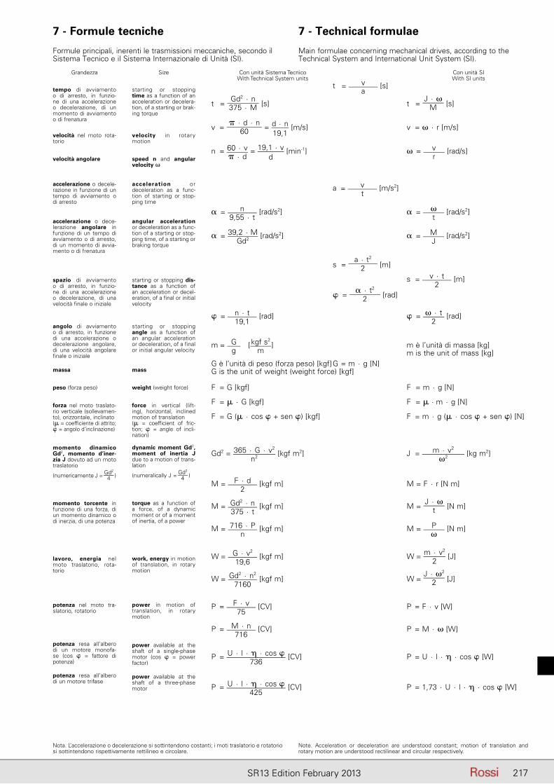
217SR13 Edition February 2013
t = va
[s]
t = Gd2 · n375 · M [s] t =
J · �M [s]
v = � · d · n
60 = d · n19,1
[m/s] v = � · r [m/s]
n = 60 · v� · d
= 19,1 · vd
[min-1] � = vr
[rad/s]
a = vt
[m/s2]
� = n9,55 · t
[rad/s2] � = �t
[rad/s2]
� = 39,2 · MGd2 [rad/s2] � = M
J [rad/s2]
s = a · t2
2 [m]
s = v · t2
[m]
� = � · t2
2 [rad]
� = n · t19,1
[rad] � = � · t2
[rad]
m = Gg
[ kgf s2
m] m è l’unità di massa [kg]
m is the unit of mass [kg]G è l’unità di peso (forza peso) [kgf] G = m · g [N]G is the unit of weight (weight force) [kgf]
F = G [kgf] F = m · g [N]
F = � · G [kgf] F = � · m · g [N]
F = G (� · cos � + sen �) [kgf] F = m · g (� · cos � + sen �) [N]
Gd2 = 365 · G · v2
n2 [kgf m2] J = m · v2
�2 [kg m2]
M = F · d2
[kgf m] M = F · r [N m]
M = Gd2 · n375 · t
[kgf m] M = J · �
t [N m]
M = 716 · Pn
[kgf m] M = P�
[N m]
W = G · v2
19,6 [kgf m] W = m · v2
2 [J]
W = Gd2 · n2
7160 [kgf m] W =
J · �2
2 [J]
P = F · v75
[CV] P = F · v [W]
P = M · n716
[CV] P = M · � [W]
P = U · l · � · cos �736
[CV] P = U · l · � · cos � [W]
P = U · l · � · cos �425
[CV] P = 1,73 · U · l · � · cos � [W]
Con unità Sistema Tecnico With Technical System units
Con unità SIWith SI units
Grandezza
tempo di avviamento o di arresto, in funzio-ne di una accelerazione o de celerazione, di un mo mento di avviamento o di frenatura
Size
starting or stopping time as a function of an ac celeration or decelera-tion, of a starting or brak-ing torque
velocità nel moto rota-torio
velocità angolare
accelerazione o decele-razione in funzione di un tempo di avviamento o di arresto
accelerazione o dece-lerazione angolare in funzione di un tempo di avviamento o di arresto, di un momento di avvia-mento o di frenatura
spazio di avviamento o di arresto, in funzio-ne di una accelerazione o de celerazione, di una velocità finale o iniziale
angolo di avviamento o di arresto, in funzione di una accelerazione o de celerazione angolare, di una velocità angolare fi nale o iniziale
massa
peso (forza peso)
forza nel moto traslato-rio verticale (sollevamen-to), orizzontale, inclinato(� = coefficiente di attrito; � = angolo d’inclinazione)
momento dinamico Gd2, momento d’iner-zia J dovuto ad un moto traslatorio
(numericamente J = Gd2
4 )
momento torcente in funzione di una forza, di un momento dinamico o di inerzia, di una potenza
lavoro, energia nel moto traslatorio, rota-torio
potenza nel moto tra-slatorio, rotatorio
potenza resa all’albero di un motore monofa-se (cos � = fattore di potenza)
potenza resa all’albero di un motore trifase
velocity in rotary mo tion
speed n and angular velocity �
acceleration or de celeration as a func-tion of starting or stop-ping time
angular acceleration or deceleration as a func-tion of a starting or stop-ping time, of a starting or braking torque
starting or stopping dis-tance as a function of an acceleration or decel-eration, of a final or initial velocity
starting or stopping angle as a function of an angular acceleration or deceleration, of a final or initial angular velocity
mass
weight (weight force)
force in vertical (lift-ing), horizontal, inclined mo tion of translation(� = coefficient of fric-tion; � = angle of incli-nation)
dynamic moment Gd2, moment of inertia J due to a motion of trans-lation
(numeralically J = Gd2
4 )
torque as a function of a force, of a dynamic mo ment or of a moment of inertia, of a power
work, energy in motion of translation, in rotary motion
power in motion of translation, in rotary motion
power available at the shaft of a single-phase motor (cos � = power factor)
power available at the shaft of a three-phase motor
7 - Formule tecniche 7 - Technical formulae
Formule principali, inerenti le trasmissioni meccaniche, secondo il Si stema Tecnico e il Sistema Internazionale di Unità (SI).
Main formulae concerning mechanical drives, according to the Tech nical System and International Unit System (SI).
Nota. L’accelerazione o decelerazione si sottintendono costanti; i moti traslatorio e rota torio si sottintendono rispettivamente rettilineo e circolare.
Note. Acceleration or deceleration are understood constant; motion of translation and rotary motion are understood rectilinear and circular respectively.

218 SR13 Edition February 2013
Catalogs
Gear reducers
Catalog A: Worm gear reducers and gearmotors
Catalog E: Coaxial gear reducers and gearmotors
Catalog EP: Planetary gear reducers and gearmotors
Catalog EPS: Slewing drives
Catalog G: Parallel and right angle shaft gear reducers and gearmotors
Catalog GX: Parallel shaft gear reducers and gearmotors for extruders
Catalog H: Parallel and right angle shaft gear reducers
Catalog L: Right angle shaft gear reducers
Catalog P: Shaft mounted gear reducersCatalog RE: Drive units on swing base
Gearmotors
Catalog A: Worm gear reducers and gearmotors
Catalog AS: Worm gearmotors
Catalog E: Coaxial gear reducers and gearmotors
Catalog EP: Planetary gear reducers and gearmotors
Catalog EPS: Slewing drives
Catalog ES: Coaxial gearmotors
Catalog G: Parallel and right angle shaft gear reducers and gearmotors
Catalog GX: Parallel shaft gear reducers and gearmotors for extruders

219SR13 Edition February 2013
Catalogs for North America and China pleasevisit our website www.rossi-group.com
Motors
Catalog TX: Asynchronous three-phase, brake motors and for roller ways
Catalog S: Heavy duty roller-table motors
Automation
Catalog SR: Servo gear reducers (worm, coaxial, helical and bevel helical units)
Catalog SM: Low backlash planetary gearmotors without motor
Registered trademarksCopyright Rossi S.p.A.Subject to alterationsPrinted in ItalyPublication dataEdition February 2013 rev. 1
Rossi S.p.A.
Via Emilia Ovest 915/A41123 Modena - ItalyPhone +39 059 33 02 88fax +39 059 82 77 74e-mail: [email protected]
AustraliaRossi Gearmotors Australia Pty. Ltd.AU - Perth WAPhone +61 8 94557399Fax +61 8 94557299e-mail: [email protected]/australia BeneluxRossi BeNeLux B.V.NL - NijkerkPhone +31 33 247 20 30Fax: +31 33 246 15 99e-mail: [email protected]/benelux
CanadaRossi North AmericaCA - Oakville, OntarioPhone +1 800 931 2044Fax +1 678 288 3658e-mail: [email protected]/northamerica
ChinaRossi Gearmotors China P.T.I.CN - ShanghaiPhone +86 21 3350 5345Fax +86 21 3350 6177e-mail: [email protected]/china
France Rossi Motoréducteurs SARLF - Saint PriestPhone +33 472 47 79 30Fax +33 472 47 79 49e-mail: [email protected]/france
GermanyRossi GmbHD - DreieichPhone +49 (0)6103 96082-0 Fax +49 (0)6103 96082-30 e-mail: [email protected]/germany
India Rossi Gearmotors Pvt. Ltd.IN - CoimbatorePhone +91 422 236 14 84Fax +91 422 236 14 85e-mail: [email protected]/india
MalaysiaRossi Gearmotors South East Asia MY - Petaling Jaya, Selangor Phone: +603 7772 7775 Fax: +603 7772 5557 e-mail: [email protected]/malaysia
New Zealand Rossi Gearmotors New Zealand Ltd.NZ - AucklandPhone +61 9 263 4551Fax +61 9 263 4557e-mail: [email protected]/australia
PolandRossi Polska Sp.z o.o.PL - WrocławPhone: +48 500 418 505e-mail: [email protected]/poland
Spain, PortugalRossi Motorreductores S.L.E - Viladecans (Barcelona)Phone +34 93 6377248Fax +34 93 6377404e-mail: [email protected] www.rossi-group.com/spain
South AfricaRossi Southern AfricaZA - Tongaat, Kwa Zulu NatalPhone +27 32 944 3505/7Fax +27 32 944 3512e-mail: [email protected]/southafrica
TaiwanHabasit Rossi (Taiwan) Ltd. TW - Taipei HsienPhone +886 2 22670538Fax +886 2 22670578e-mail: [email protected]/taiwan
TurkeyRossi Turkey & Middle EastTR - Çiğli - IzmirPhone +90 232 328 1092 Fax +90 232 328 1093e-mail: [email protected]/turkey
United Kingdom Rossi Gearmotors Ltd.UK - CoventryPhone +44 2476 644646Fax +44 2476 644535 e-mail: [email protected] www.rossi-group.com/unitedkingdom
United States, MexicoRossi North AmericaUS - Suwanee, GeorgiaPhone +1 800 931 2044Fax +1 678 288 3658e-mail: [email protected]/northamerica
Responsabilità relative ai prodotti e al loro usoIl Cliente è responsabile delle corretta scelta e dell’uso del prodotto in relazione alle proprie esigenze industriali e/o commerciali, salvo il caso in cui l’utilizzo sia stato raccomandato da personale tecnico Rossi, debitamente informato dal Cliente delle proprie necessità operative. In questo caso, tutti i dati necessari per la selezione dovranno essere comunicati fedelmente e per iscritto dal Cliente, riportati nell’ordine e conferma-ti da Rossi. Il Cliente è sempre responsabile della sicurezza nell’ambito delle applicazioni del prodotto. Nella stesura del catalogo è stata dedicata la massima attenzione al fine di assicurare accuratezza delle informazio-ni. Tuttavia Rossi non può accettare responsabilità dirette o indirette per eventuali errori, omissioni o dati non aggiornati. A causa della costante evoluzione dello stato dell’arte, Rossi si riserva la possibilità di apportare in qualsiasi momento modifiche al contenuto della presente pubblicazione. Il responsabile ultimo della selezione del prodotto è il Cliente, salvo accordi diversi debitamente formalizzati per iscritto e sottoscritti dalle Parti.
Product liability, application considerationsThe Customer is responsible for the correct selection and application of product in view of its industrial and/or commercial needs, unless the use has been recommended by technical qualified personnel of Rossi, who were duly informed about customer’s application purposes. In this case all the necessary data required for the selection shall be communicated exactly and in writing by the Customer, stated in the order and confirmed by Rossi. The Customer is always responsible for the safety of product applications. Every care has been taken in the drawing up of the catalog to ensure the accuracy of the information contained in this publication, however Rossi can accept no responsibility for any errors, omissions or outdated data. Due to the constant evolution of the state of the art, Rossi reserves the right to make any modification whenever to this publication contents. The responsibility for the product selection is of the customer, excluding different agreements duly legalized in writing and undersigned by the Parties.