SR03-01NMEA to synchro converter user manual(REPEATER).pdf
45
SRO3-O{NMEA to synchro converter User Manual n( .{'6candinavian Micro Systems AS (:airi"",2.o2 Juno 07)
Transcript of SR03-01NMEA to synchro converter user manual(REPEATER).pdf

SRO3-O{ NMEA to synchro converterUser Manual
n (.{'6candinavian Micro Systems AS (:airi"",2.o2 Juno 07)

SR03-01 User lvlanual
1
3 HOWTO READ THE "NORMAL DIsPI.AY"
ISR03-99DOC-01 tr/lanual Rev2-02 doc Page2ol44 ' Scandinavian [,4icro Syslems AS

SR03-01 User [.4anual
9 COMPASS COMPARE & MANUAL SWITCHOVER.. , , . . , . . . . . . . . . . . . . . . . . . . . . . . . . . . . , . . , , . . . . , . . . , . . . . , . . . . . . . . .23
9.1.1 AuToMAlcSwrTci lovERAFTERREsEr, , , , , , . , , . . . . . . , . , , . , , . , , . , . , . . . . . . . . . . . . . . ,239,1.2 MANUA1Sw|rcHovERWHFNcoMpasscoMpAREA1ARM.. , , . , , , . , , . , , . , , , , , , . , , . , , . . . . . , . . , , . , , . . , . , , . . , . . . , . . , , . ,24
HOW TH E ALARM SYSTEM WORXS... , . . . . . . . . . . . . . . . . . . . . . . . . . . . . . . . . . . . . . . . , . . , , . . . . . . . . . . . . . . . . . . . . . . . . . . . . . . . .251S
11 HOW TO |NSTALI SRo?.O1 - . . - . . - . . . .
SR03'99DOC-01 lvlanual Rev2-02.doc - Page 3 of44 , Scandinavian Micro Systems AS

ffieater-SR0301 User llanual
2 Introduction to SR03-01
Scandinavian Micro Systems provides a series of NI\,4EA 10 SFchro Converiers for drivingvadous "old style" lllechanical Synchro Repeaters using Digilal Heading Data.
All ofthe unils can read various digital serialformats as supplied by modern gyrocompassesprimarily NIIIEA 0183, but also olher propdetary formals.
SR03-01 N lV EA to Synchro Converter models can be configured to drive different type ofMechanical Repeaters depending on vollages and frequencies required.
2.1 Single Unit operation w/one Gyro CompassThe ScanRepealerw SR03-01, NMEA 10 Synchro Conveder is shown in a system using theexisting Gyro Repeater Synchro Disiribulion Unit - driving the existing mechanical repeatets.
Figure 1 SR03-01 with one gyro.
2.2 Single Unit operation Wtwo Gyro CompassesThe NMEA to Synchro Converter units willallow you lo exchange yourold cyro Compass, bulkeep the old lvlechanical Repeaters and the old cabling,lhus saving time and moneywhenconverting to a new and modem Gyro Compass - see drawings below.
Figure 2 One SR03-01 wilh two gyros.
Scandinavian l\,|icro Systems AS
--.i fr:."\
J \Y.'/
SR03-99DOC 01 Manual Rev2-o2.doc - Page 6 of zl4
, , i
f SR03-01 User Manual
*-*{1-"
i-t(r6bl)rl \Y/
;scaxlG#s
2.3 Redundant Operation w/one Gyro Compass
Redundancy can be achieved by connecting two (2) NlllEA to Synchro Converlers in])arallel.The ligure betow shows a Block Diag€m using one gyrocompass and lwo NMEAIo Synchlo
Figore 3 Two redundant SRo3_l)i with one common gyro.
The gyrocompass feeds the same heading to both ofthe two NMEAIo Synchro Converlers- Onlythe piimary SR03-01 must be aligned to the mechanical synchro repeater(s) The primaryandsecondarySRO3-01 willlhen run in "parallel" and be synchronized producing the sane outputsrgnals.
\ryhen the primary SR0?01 fulls out - an extemal changeover Ielay will switch out primary SR03-01 synchro signils and in the semndary SR03_01 synchro signals The primary SR03-01 controlslhe extemal changeover relay with a s tchover relay control signal
SRro$ggDoc-01 Manual Rev2-o2.doc- PageT ol44 - Scandinavian Micto Systems AS

SR03-01 User l\ranual
2.4 Redundant Operation W two Gyro Compasses
A higher degree of Redundancy can be achieved by having lwo gylocompasses each driving ils"own" NI\IEAto Synchro Converter as shown in thefigure below.
l------------1 _f l - 5 t
lii F,"9::*-l .r";$
| \ta:. v/
Figure 4Two rcdundantSR03-01 with lwo common gyros.
Boih gytocompasses teeds heading to the two NI\IEA lo Synchro Converte.s- only the primarySR03-0 1 m usl be aligned in respect to the mechanical repeater.
Should one gyro compass and one SR03-01 fail the systems will still operate.
2.5 Optional Remote Control Unitll is possibleto connect an extemaldisplaycont.ol unitto the SR0301 also called theRemole Conlrol Unit. The Configuntion Menuis the only difference between the buill in LocalControl Panellhe Remote Conhol lJ.il. TheRemote Control Unitcan not be used toconfgure lhe Syrcrro Formal
Figure 5 Remote Control UniUSR03-012-6 Automatic Shut-Down & Alarms
The ScanRepeatern NMEAto Synchm Converlers have built in automatic 'shut-down", in caseof short-circuit, over-cunent, crilical temperature.
Alloflhese alams are OR-ed into one alarm function so that any one of these conditions will startflashing the Alarm light on the Front panel, drop theAlarm Output Relay and start the SoundAlarm. TheAlarm Output Relaywillalso aclivaie in case of Power Loss to the unit.
To silence the Alarm; Press the ALARI\,4 Button (Red). Delails about the alarm can be rcad fromJhe display.
{ I SR03-9SDOC01 l,lanual Rev2-o2.doc - Paoe 8 of 44 - Scandinavian l\,4icro Svstems AS
t' 'l&*-uSR0$01 Ljser Manual
2.7 Block diagramThe block diagram illustrates allinpuls and oulputs as wellas some of lhe software funclionsinside SR0+01.
of SR03-0{
Scandinavian Micro Systems ASRev2{2.doc - Page I of44 -
SR03-01 User Manual
3 How to read the "Normal Display"
Primary Serial Input Heading I\trr.:359.3 (HDt) " NMEA HDT sentence heading rcceived and valid. I0.0 - 359.91..'tl1 : AIARM (ANs ) " Anschulz C-Bus serial heading received with alarm,"s1: r,osr(RGc) " RGC 1 l serial heading in missing or fails.\rr1: rDrE (---) ,' Serja' input channel not configured,
Secondary Serial Input Heading 2Status equalPrimary Serial Input Heading 1.Used as backup for the primary heading inpul.
lndicates heading source fo. Synchro output' t " I\,4issing heading source.
Heading sourced frcm H1 when line 1 ot H2 when line 2.
8
19.:{ 'SR03-99DOC 01 lvanual Rev2-o2.doc - Page 10 of44 - Scandinavian Micro Systems AS
Synchro Output Heading status"out:359.3" Synchro output heading is curently359.3 degree.
Compass Compare gtatus
,,t41-s2:arnlrMz Devialion exceeded the conllgutable limit =>Alarm.
Synchro format I Alarm status"50t lz (50, /0-20) 360x" Synchro output fomat..'Alar[ : No heading in!"
Temperature inside SR03-01
Ex- Alarm message. See chapter 70.
\+4 3' c" 43 degree celsius inside the SR03-01 cabinet-
Temperaiure exceeding 70 is criticaland willtum off synchro output.
Mains inlet current consumption.1.6 ?\np" The curenl consom ption at mains inlet (typ;cally24 V DC).'Afan" Consumption exceeded the coniigurable limit is ciitical. Synchro outputwill be iumed off.

'ee3'dc6SR03-01 User Manual
4 How to use the keysThe Display & Contol Panel has five positive action switches, with a distinctsnap when ihey are pressed and engaged.
Synchro Power KeyPr€ss 5 sec to tum Synchro outpr.t off. When setting the synchro ouFut in?owered Off state il will be d;splayed as an alam event.Press 1 sec to turn Synchro output On again.
Acknowledge alam keyonce to acknovledge allalarms. The.ed lighlw;llthen be tumedon untilthe Alarm condition is rectified and then tumed off.
In Normal Display Mode
Enter keylo enler the Menu.
ht Up keyto increase the backlighl.
hi Down keylo decrease the backlight.
In Menu Mode
ot the following keys performs the tuncton indicated by lh€shown'[.....]" in the display lino4.
- Enler keyAclivate the edf rrode to change a menu item.Accept changes.Exit menu,
Next item in menu listIncrease or change value.
Next ileft in menu listlncrease or change value,
Manual Rev2-oedoc - Page 11 of 44 - Scandinavian Micro Systems AS
Display in Normal Display Mode
Display in Menu Mode
Display;n Menu Edit l\lode

SR03 01 User lvanual
5 How to use the Main MenuThe table below shows how to enterthe main menu and how to walk through alllhe possiblemenu items. The menu has a 60 secondslimeout. The display willthen leave the menu
irs list-:
6#ffii
SR03-01 willafter resel and when running normallyshowthe "Normal Displal informalion-
r I t#;t [r f-:Pr-lPress Ell::J to enter the main lllenu.l/lanual switchover is the first menu item. When usingboth heading 1 and 2 serial data input, it is possible tomanually select one of then as soulce for the synchrooulpuL
u @ E p,"r. EJ o, @ se'ect a new headins sourceWhen lvechanical repeater heading differ from synchrooutpul heading use this menu lo align lhe I\,4echanicalrepeate(s). Change the'Repeate! headiDq" toeoualthe comoass rose headinq.
LlJegrLa j p,""" E]ro, n"x o, [@ ro arisn sRo3 01
-selll|lG*
Seleci coraect protocolfor pdmary sedal input channel'1. See chapter 12.5.1 for allavailable protocols. Line 3indicates ifSR03-01 can read the serialdata in. Theprotocol and baud rale need to be conect.
EE.i @ p,""s Elro, n""r o, @d to chanqe rhe p,orocot.Selecl conect baud rale for primary serial inpulchannel'1. Select between 4900/9600/19200/38400.Line 3 indicates if SR03-01 can read the serialdata in.The Drolocol and baud rele need io be conect.
EfErFtt!E1Ll_J p,""" EJ to, n"rt o, E4 to chanse baud 'ate.
Seleci conect protocol for secondary/backup serialinout channel 2. See chaptet 12.5.1 for all availableprotocols. Line 3 indicates il SR03-01 can tead theserialdata in. The ptotocol and baud rate need to be
EJ t{41 t-rl p,""" EJ to, n"x o, @ro chanse tne protocot.
#ffimSelecl conect baud rate for backup se al 'nputchannel 2. Select between 4800/9600/19200/38400.Line 3 indicaies if SR03-01 can read lhe serial data in.The protocol and baud raie need lo be co(ecl.
|?o'nEvar Eil press [J to, nen or @ to chanse baud late.Selecl N[/EA sentence lype(s) for the se aloutputchannel. Select blw NMEA sentence $HEHDT,$YXALR of both.
..s,ir. SR03-99DOC-01l\,4anualRev2-O2.doc Scandinavian l\,4icro Systems ASPage 12 ot 44

SR0301 User Manual
r usingsible lo
sible
100
|aI
" t o
Line 3The
loo
Press [:J for next or l:]J ro select sentences.Selecl baud €te for NMEA serialoutput channel.Selecl between 4800/9600/1 9200/38400.
lElfor next or lA :J to chanoe baud rate
Sei the alarm l;mit for compass compare function inrange from 0 to 5 degrees, Defaull value is 2.5 degree,See chapter9.
Press L- -l for next orElSto chanqe comDare limit,Sel the maximum limit for the mains inlet currentconsumption ffom 0 to 20 amperes. Default value is 16ampere.
Press \:J for next or l:l::l to chanoe currcnt limit.Setlhe limil for detecling a siuck rcpea1er. See chapter6.5.
Press (:J for next or Ll::J to chanoe senslf needed - il is possible io correctlhe displayscontrasl. Values ftom 0 to 100 %.
LElfor nen or Ell:IJ lo chanoe LCD conlrast
The "sldchio output hfo" displays:1. Synchro slandard type(ArEcbltz 2)2. Reference frequency (60H2)3. Synchro RefVoltage (60)4- Synchro Phase voltage range (0-24)5. Gear Ral io
Press [-:J lo see the next menu item.These none-editable menu elements show thesoflware version and build date forthe microcontrollerIn the SR03-01 'Controller Panel". Non editable menu.
Press [:J lo see the next menu lem.This none-editable menu element shows the softwareversion and build date forihe microcontroller in iheSR03-01 Conlrcller boafd". Non editable menu
Press l: .110 see the next menu item.
bR62{2doc Page l3 o l44 Scandinavian lllicro Syslems ASNS AS

SRO3-01 User Manual
-E last menu entry of the Ma#inu is the exrt l
funclion. Press the EdiUEnlet E!9 bltlor and SR03-
5.1 A men u example of how to change Serial lnputbaud rate
We wlllbelow go through - as an example - now to change the ba!d rate setting forihe serial
heading jnpul1
SR0l-0t w.t-afrp res"t "rd,^-. r 'u_r.rg ' tomaly
show r ' re Norrdl Dicpj l_I fo n" or T"e le 'r
I rMenul indicaies that EllS w r acllvate lql1v!ry - l
lo enLeI1lqq?D !E!!-tr,'tinuat switclover is the trsl r.enu ilern
@ E io tind the "Headins I Baud
ttre uieiwltttnen return to the operaijon displaymodus NomalDisPlaY'
SRO3 99DOC-01 Manual Rev2'02 doc Page 14 ol44 Scandlnavian Micro Systems AS

&J
I_t
SR0301 User Manual
6 How the Synchro Output worksYou willfmd lhe technicatspeciication forthe Synchro output in chapter 72lpchrical
ial
Cl The synchro signalsTo@ntrola synchro motoayou need lhreeiEse signals S1,S2 and 53 and two*fence signals R1 and R2_
ns ofthe synchro signals are:
.-':
s
b R 2 = A s i n ( l l tbS3 =A sin @t sin (0)bS2 = Asin ( t) ts in (e + 1201bSt =A sin oli sin (e + 2401
molors is orcan be used as an ACSR03-01 is designed as an AC synchrobr. The five signals (S1,52,53,R1,R2) have a
modulated frequency, norma yo. 500H2. The reference
ity for alllhe signats need to be in phase ifLml possible to conlrollhe synchromotor.
t ot us any othef refefence signet (Rt ,R2) than SRO3_01 outluts.
Synchro Output Operation
Artomatically Synchro Output Shutdownsignalwilibe faded out and disconnecled if minimum one ofihe three critical atarms in the table below occurs.
q|nchrc Disconnected State (Atarm active)
*!]:Tl:.1ol"S,n".synchfo ourput wi be disconnected in rhe fo owing way:rlE synchro oulpr,l signalwillbe faded out.
,.r, r'rt*rr4ir;rl
TIE ClEnge Over retay signatwi ctose the NC contact and open the NO contact.IE Abrm Relay wll ctose the NC contact and open the NO contact.TlEAla.m Light will start flashinq red.nE Ala.rh Sounder witt start putsatrno
qdE Soft Startcidrdilions are removed lhe synchro oulput will Iollow a soft stad algorithm:Sounder will stop Pulsatinq.Ltli will siop flashing red.R€laywillclose ihe NC contact and open the NO contact.
kr|d Rev2-02 doc - Page t5 of zt4 Scandinavian lvlicro Syslems AS

@
SR03 01 LJser [,4anual
4. The Change Over relay signal ll open the NC con{act and close the NO contact.5. The synchro output signalwillfade in. (2200 msec.)
6.3 Synchro Output Recovery Functionlf SR03-01 looses the 24 VDC inlet powersupplywhen the mechanical repeaters aIe running theoutput heading will be slored in a Non Volalile memory befote shutting down the sysiem. WhenSR03'01 restarls the stored heading (recovered heading RH) will be used to synchlonize themechanical repeateawiih the serialdata input heading.
6.3.1 Recovery aftershutdown at high speedlfSR03-01 shuts down when the mechanical Iepeaterc has an high speed, the mechanicalreoeaters Dositions when it stands slillwillbe unknown for SR03-01. This williead to one oI moredegrees misalignments. The effect oflhese will dependeni on the mechanical repeater type andspecification. lf this should happen - just align the SR03-01 once more.
6.4 Synchro Output OverloadSR03-01 measures the 24 voltage power supply input curlent. The following overload ALARMalgorilhm is design in SR03-01:
. l f lheaveragecurent in320msec.exceedslheCurrentLimit i lwi l lbegeneratedanOvedoad alam.lhe Currcnf Llmrl is changeable in ihe sel-up menu.
When the synchro outpui is overloaded, the synchro oulput will be tumed ofJ in 10 s,"conds. Thecurrentwillthen falfdown to undet lhe Cunent Limit and SR03-01 willlhen soft-sta(lhe synchroourpur agarn.
PRECAUTION: lf this fepeats successive l0limes - SR03-01 will NOT conlinue to selup lhesynchro outputagain. The user mustlhen powel cycle/resei SR03 01. The system needs
lf the synchro output runs for more than 60 seconds wilhout any Ovedoad alatm the 10 tirnescounier willbe reset to 0.
6.5 Stuck Repeater indicatorSR03-01 has a buih in load test thal will delect if a lvlechanical Repealer is sluck and give aWarning (non-critical alarm). SR03-01 senses the abnomal/unequal load when a lepeatel getsstuck. lf lhe stuck repeater as rem oved the st ck rep€aler indicator will be Iemoved,
6.5.1 Stuck reDeater calculationTo calculale a stuck repeater the Rate of Turn need to be between 0 and 60 degfees per minuleand the synchro signalrequ;res rotating one turn. lt is noi possible to do this calculation iltheheading stands still.
6.5.2 Stuck repeater indicationSiuck repealerwaming willnottrigger the alarm output relay and lhe buzzer. The ALARM led onthe conlrolpanels and a blinking line in the display will indicale the fault-
6.6 Optional mechanical Repeater Lamp OutputSR03-01 has a lra nsformer for generating powef 10 the l,lechan ical Repeatel Lig hi for somespecific synchrc formats. The Light willsink effect from the output reference signalso the Lightload will be add;lional to the normal synchro reference mechanical repeater load. Se the 77.2.6Synchro Signal Output Connections including the Repeater Light connected foI how to connectihe transiormer and addilional information.
. . 1 ,
SR03-99DOC-01 l,lanual Rev2 02-doc - Page 16 of 44 - Scandinavian [,4icro Systems AS

SR03-01 lJser l\Ianual
.|g the
I
9and
IM
Thelclllo
UIe
7 How to Configure the Synchro Output Format
7.'l Cautionl Disconnect Synchro LoadlBefore configuring the Synchro output type discorrect the SR03-01 faom synchro phaseSl,lS2yS3 and reference R1/R2 wires lo the mechanical repeatercl
lb possible to damage synchro repeater motors when generating to high synchro signalvoltagelr lovr vollage repeatersl
t2 Caution! Select Correct Phase voltagelbooste. reqdres phase voltage eqralas given for lhe Mechanical Repeater. The
icalRepeater can be seen up on as a transformer so lhe Refeence voltage R1/R2 willbeto a secondary vollage atthe Phase signals I\,4RS1/MRS2ylrlRS3. lfthe Phase
returned from the lvechanical Repeater is higherthan the Phasevoltage generated in theS1/S2/S3. lhe Phase voltage amplifier in SR03 01 need io sink the retumed power
egain generates more heat inside the converter.
l\,4echanical Repealer
l\-4RS1 =< S1L.4RS2 =< S2IVRS3 =< 53
Gis
that SR03-01 generates equal phase voltage (S1/S2/S3) compared with given orMechanical Repeater values ([4 RSl /MR52[]| RS3) !
the correct Phase voltage for the Mechanical repeatermechanical repeeterc you willonlyfind reference voltage and frequency given for the
-otor. SR03 01 requjres bolh the Reference and Phase vollages given with lhe correctaalio fof the mechanical reoeater. Follow the Drocedure lo find the coffecl Phase
alf repeate(s) from SR03-O1. See 11.2.5 Synchrc Signal Output Connectons
l|e synchro cuslomize menu to setup SR03-01 with the correct l\,,lechanical RepeaterVoltage and Frequency- R1/R2- Do not care abouttbe Phase voltage_ See 7.6
lo customize the Synchro Oulput.
ONLY lhe Reierence signals Rl/R2 from SR03-01 to only ONE mechanical repeaterlE mechanic€l repeaier phase signals S1/SZS3 be disconnected.
l|n llE compass manually around. Ihen measure and lind the maximum RIIS AC VoltageMRS1/MRS3. This maximum RIVS voltaoe is then the "co.rect ohase vollaoe".
I\,4echanical Repeater Muiti lveier (V-AC)
lon
I6
AS llanual Rev2-o2.doc Page 17 ol44 Scandinavian l\,4icro Systems AS
SR03'01 User Manual
Then you can calculale the transformer raiio: TransRaiio = VRI,R2 / Vmax(tMRS1/MRS3).
7.4 Entering the Synchro Format I'llenuTo entel the "Select Slnchlo Fomat, menu, it is necessary lo follow this procedurc
1. Press attthe three bu"."" E @.8 "xact
simuttaneouslv in minimum 5
2, The userwillthen enier the ,'s6t€ct slnchro Fodat,, menu.
Release then all buttons.
This is done in this intricate mannerto prevenl unauthodzed personnelto get access to theconfiguraiion menu.
7.5 How to change Synchro Output Fomat (example).Caution ! Disconnect Synch.o Load before changing lhe synchro fo.matl
Page 18 ol 44 - Scandinavian l\,4icro Systems AS
SR03-01 will after reset and when running normallyshow the 'Normal Display' information. To enter the"Sel6ct sinchro Fonat', menu - press all thethaee buttons simultaneouslv.
t_rl t@ E p,""" EIfiIIIJ in 5 sec. and then retease ar.SR03-01 do now delivefAnschulz 2 formai with 60H2,60 V AC reference and 0-24VAC phase signals with agear ratio of360. Let's saywewantthe Gazelle 1synchrc format. Do as follow.
|. aFF-lISEJ E t_Pg_l
Press ElilJ to be able to chanoe.The blinking anow >"indicales edit mode.
{J E"r"""
E o,EJ,o ".tect,,cazette
1', formal
EJ rEuntEmRJ a Press l& to accept tne new svnchro format.
Changes will be stored in non-volatile flash memory.The set-up willnot be lost if lhe unit is turned ofl
tq @ElE pr""" La to s"u" o, [!Jro cancet chanoes.The user willthen relum lo the operation displaymodus "NormalDispla/.
\ - '
SR0399DOC 01 Manual Rev2-o2.doc

SR03 01 User lvanual
7.5 How to customize the Synchro Output FormatCaulion ! Disconnect Synchro Load before cbanging the synchroformatl
E3. y lh e i
" l;JoH; l*"1
=
I;tI.
I.
lrAS
xk
It none ofthe standard defined synchro types fits the requirements - the user has the option totully customise lhe synchro fomat as desc bed below.
SR03-01 willafrer resel and when running normattyshowlhe "Normal Displa/ info.mation. Toenterthe"Seleet Synchro Fodat menu press allthe threebuttons simultaneous
Press L:l::l:ll: J in 5 sec. and ften retease att.SR03-01 do now deliver "Anschutz 2. fo.matwith60H2,60 V AC reference and 0-24 VAC phase signalswiih a gear mtio of360. Let's saywe want tocuslom;ze the synchro format. Do as follow.
Press t:l::l to be able lo chThe blinking affow '>'indicates edit mode.
Press L : jod -J lo selecl "custd se!up' formal.
Press l:l:J 10 accept lo enter ',custoE setup',
To change between 50/60/400/500 Hz press l:jj key
and select newfiequency. nccept witn tne @ tey-
Press t: J for next or Ell:l lo chanoe lhe frequencv.The user can change the reference voltage withvoltage slep from 0 to 110 V AC.
Press L-:--l for next menu or el:y to chanoe the
The user can change the phase voltage with 1 vottagestep from 0 to 100 V AC.
tErfor nexl menu or |:]IJ to change the
1 Manual Rev2,o2.doc Page 19 of 44 Scandinavian Micro Systems AS

@
SR03-01 User llanual
7,7 Connect synchro LoadWhen finished the change of lhe_!y!g!ro output type you should do the fol'owing:
1. Press the Synch.o Off L ,--, key in 5 seconds to disconnect and fade out the synchrosignals S1-3 and R1-2. This is an a'arm situation where ihe display indicales "stdcltlo
z. Press tle @ reyt mutelhe buzzer3. connect lhe mechanical repeaters cables - R1,R2,S'1,S2,S3 - to SR03-01.
4. Press the Synchro OflL-J key in 1 second to connect and fade in (soft start) thesynchro signals S1-3 and R'1-2. The "stDchEo out PoEER'€d off"willthendisappear in the Normal Operation Mode display-
Scandinavian l\Iicro Syslems AS, i , t
I
The user can change the gear ratio in slep with 1 from1:1 io '1:360.
E aEotrterg E f - I rEotrlPress L3 for next menu or gI1to chanse the Cearralio-This is the lasi menu item.No changes => no request for Save oI Cancel.
l.-"*l L!_l Press L@to bave the -custon confis" menu.Changes will be stored in non volatile flash memory.The selup will not be losl ifthe unit is tumed off.
EJ t#sdE ,,"". EJ,o a"u" o,E ro cancetchanses.The user will lhen return to lhe operation displaymodus "NormalDisplaf.
SR03-99DOC-01 Manual Rev2-02.doc Page 20 of 44

rter'ffit-f- - le Gear
I-l-enu. I
f-l- l
Dhro
AS
SR03-01 User Manual
8 Quick Set -up Guide
,',liClr{lt;.>...reaate!-
Disconnect Synchro load from SR03-01. 11.2-5 Synchro Signal OutputConneclions.
lvhen replacing an old Gyro: Check the exislingrepeaiers. One stuck repeater w:ll sink 5-t0 times morepowef than normal. Check mechanically all repeatercand lhe aulopilot. includrng the synchro brushes.
To configure SR03 01 we need thefollowing data forthesynchro molor in the mechanical repeaie(s):
. Cofiect reference voltage R1/R2
. Correct phase voltages 51/S2yS3.
[ . Reference frequency.I
I ' Geat ratio
Check Gyro or lvlechanical Repeatermanual.
lFr don't knowthe correct Phase voltage => Find itl 7.3 Find the correcl Phase voltagefor the lvlechanical repealer
Fgure SR03-01 with lhe correct refercnce and phase
Fs.DE of the standaad synchfo fypes irts - use thealDrn Setup" to configure by hand frequency,bence. Dhase voltaoe and oear ratio.
7.5 Howlo change Synchro OutputFormat (example).
7.6 Howlo cuslomize the SynchroOulput Fomat
!d protocols and baud rale for masler heading 1 andE al- backup heading 2.
5 Howto use lhe Main Menu
F l-- J in 5 seconds to tade out the synchrold- Connect mechanical repeate(slo the SR03-01
FUR2 and S1/S2/S3 signals. Press L J in 1Fd to fade in lhe synchro signalagain. VerifyFalconnection.llE mechanical reoeaterts)
1'1.2.7 Cabling faults and ihe relaiedheading eror-
5 How to use the l\,{ain l\,4enu
'6tn hro load. Nonnally a mechanical repeater
Fo.2 to 0.7 Amps @ 24 VDj-qeck current with
lFut synchro load. Press l:5J - power buflon! d (ssec) / on (lsec) the synchroFnprfier.
3 Howlo read the "Nomal Displal
lEAl-rn rehy output?I
11-2.10 ALARII Relay Connection.
Fkm ALR NMEA sentence outpul? 5 Howlo use the ll,4ain l\,4enu
lfanual Rev2-o2-doc - Page21 oI44 - Scandinavian Micro Systems AS

SR0101 lJser Manual
Scandinavian l/icro Sysiems AS
Use ihe NI\,4EA HDT output? 5 Howlo use lhe Main lvenu
Usethe Optional Remote control LJnil? 11.2.13 REII IOTE CONTROL PanelConnection
Changethe cufient limiterforthe SR03-01 inpul power.(Default Current limit =16Amp @ 24VDC).
5 How to use the lvain llenu
change'Compass Compare Umit'- default is 2.5degree. Valid when dual heading inpul (both ser;al inpul1 and 2).
5 How to use lhe lvain lvenu
SR03-99DOC-01 [IanualRev2-02.doc - Page 22 ol44

K
Panel i
lI
SR0301 User IVanual
9 Compass Compare & Manual SwitchoverTIE Compass Compare funclion compares two heading sources and gives an alam ifthefference exceeds the Canpass Comparc Linit (Defaull2.5 degrees). This limit is adjuslable inlE Main Menu in lhe range from 0 lo 5 degre€s.
7 Compass Compare/Heading flow
Automatic Switchover after reset
. From Inlernal Recovery heading to Serial Heading 1 (H1). Frorn Inlemal Recovery heading to Serial Heading 2 (H2). F.o.n beading 1 (Hl) to Heading 2 (H2).
lEding source to the Synchro output can be automatically switched :
I From Intemal Recovery Heading to Heading | (Hl) or Heading 2 (H2)|Eset SR0301 willexecute an aulomatic swilchoverfiom the inlernalrccovery heading (RH)
.l mn lolaiile memory and to one of the serial Heading 1 (H1) or Heading 2 (H2). ThelEdirg 1 (H1) or2 (H2) thal SR03-01 reads first will automaiically be selected as source
Slrxfiro Output.
qs1 Manual Re\,2-02-doc - Page 23 of 44 Scandinavian l,licro Systems AS

SR03-01 User Manual
After power up SR03-01. it tequires that one of the heading inpul sources 1 or 2 is valid (teceived
and valid). lf not - ihe auiomatic switchover will nol be execoted The synchro heading will lhenslill use the inlernal recovery heading.
9.1.1.2 Automatic switchovertrom Heading I (H1) to Heading 2 (H2)Wewilllook ata siluation where both serialheading inputs is configured' received valid and wehave no compass compare alarm. Nomailythe heading 1 (p mary) is sourcing the synchtooutput. lfthen the heading source (gyro) 1 falls outlhe heading 2 willbe automatically swilchedin.
For safety reasons the artomaticatly switchoverfunction willnol be handled back again fromheading 2 to heading 1.
9.1.2 Manual Switchoverwhen compass comparc alarm
lfthe difference belween heading 1 and heading 2 exceeds the compare limit we w lhave aCompass Compate Alarm siluation and the automatically swilched ovet will NOT be executed.The user then needs to h andle e Manual Switchover operalion li is possible lo manually switch:
. From heading 1 to Head;ng 2.
. From heading 2 to Heading 1.
Only Manual
Heading 2Serial (H2)Heading 1
Serial(H1)
Figurc 8 Automatic / manual switchover diagnm'
* ' SR0399DOG01 Manual Rev2{2.doc - Page24 of 44 Scandinavian [Iicro Systems AS

I then
SR0+01 User Manual
How the Alarm System Works
;l Alarm levelshas three differenl alarm levels: Waming, Alam and CriticalAlarms.
Waminga lraming" occuas the lollowing will be executed:
a NMEAALR sentence.a m€ssage in the LCD display-lhe Red Alam Led
W**br
Scandinavian Micro Systems AS
tobhed
m
AlarmaH.litch:
?larm'occurs lhe following willbe executed:a NMEAALR sentence.a message in the LCD display.lE Red Alarm Led
will be activated
Alarmlalarm' occurs the following willbe execuled:
a NMEAALR sentence.message in the LCD display.
Red Alarm Ledwill be activated
Relay OnSynchro Output.
Levels Summary
sourcesAla]m identitication
llanual Ref2 02.doc Page 25 oI 44

10.3 Alarms in l ine 3 in Normal Display10.3.1.1 Alarm indicat ionslflhere are one or more alam situalions line 3 in "Normal Displal will toggle between sctivealam wlth the highest priority and lhe Synchro outputfomai The table below shows the dlffetentalarm situalion.
SR03-01 User [,4anual
10.4 NMEA ALR & ACK serial output Alarm syslemSR03-01 has an interface fof CA[,4 (CenAalized Alann l\,4onitor;ng) systems lt is based on twoNI\,lEAtransmil sentences: ALR Sentences "Sei Alarm State" and one receive ACK Sentences''Acknowledge alam". Since SR03 O1 do not support UTC (universallirne cootdinated) this fieldis empty ( ' , , ) .
10.4.1 NMEA ALR Sentences "Set Alarm state"
SYXALR.hhnrrss.ss,X/.X,A A,c _c hh<CR>.1 F>
10.4.2 NMEA ACK Sentences "Acknowledge alarm"
$-ACK,XXX'hh<CR><LF>
Ala.m text lvpe :n field [F5]. Commeits1(Hiohest)ffi Svnchro outout controlled with JPOWERI button2 Critical intemal temperature or overload.3 [,4issinq serialdata headjng in.
SR03-01 needs to be aliqned after power-up.
5 ffi Requires a human conr,olled manual swilqlQle!6 ReDeaters are under al iqnin9.
One or more repeatels afe detected as stuck.Normal No alarms => Synchlo type infomation.
Sentence DescriDiion$ Start of N[/EA sentences.YXALR Set Alarm state command.' l ;me o'alarm conotror chanqe, U lS. NOT SUPPORTED ( ' ,1
Unioue a lafm numbet ( idenl i f ied a l r lam sou'ceArarr condirion LA= fhreshold exceeded. V=ntql!e9!9!),qtarm-sactnowtedqe.tate,A=Acknowledse.V=uracknowledgC!.Alarn descriplion texl. See Tabte 2 NMEA Alarm idj!lj!93!!9!
-hh Checksum.Teleoram termination.
Senlence Descriotion$ Slart of NlvlEA sentences.ACK Acknowledqe alarm.XXX UniqLe a€rm number ( ident l ler) al alarn source.'hh Checksum.
Teleqram terminailon.
SR03 99DOC-01 IVanual Rev2-o2.doc Page 26 ot 44 Scandinavian IVicro Syst€ms AS

E SR0101 lJser lvanuat
10.5 Alarm acknowledge
lo.5.l unacknowledgedAlarmsbfent
Idd
the RED ALARM LED is btinking it indicates thal there are one or more atarms that are not
d(nowledged. To acknowtedge the alarm press the E uutton or sena a tuen aCK
ing theB Uuiton on lhe Conlrol panet all unacknowtedged atams wi be|wledged. The RED ALARM LEDwjllstop btinking and the buzze.wi be muted. Atarmsthat
to the SR03-01.
Button Acknowledge
exist any more willdisappeaa trom the Panelwhen lhe alarm is acknowledoed.
l{llrEA ACK acknowledgeACK sentence can acknowledge one alarm tD. When the SRO3-O1 receives NMEA
I will acknowledge only that alarm lD. tf there are other unacknowledged atarms the REDlM LED will still be blinking indicating unacknowtedged alarms.
rms a.e acknowledged lhe RED ALAR[,4 LED willturn sleady on to indicate that there arelhat have been acknowledged and still is active.
Scandinavian Micro Systems ASllanuaf Rev2-o2.doc - Pagez7 of 44

SR03-01 User [,4anual
11 How to Install SR03-01
11.1 Mechanical MountingThe SR0!01 must be mounled vertical'y to allow free airflow around and through the unil. Thereare four mounling holes with diameter 8mm.
When the temperature inside the unit increases an Air Fan mounled ins;de the unitwillstad toforce airthrough the enclosure and outthrough slots atlhe top of bolh sides.
- lt is necessarylo keep these openings fiee from obslrucfions,
Figure 9 Unit Physical Layout & Measurements
11.2 Cabling & ConnectionsUse shielded cables. The cable glands a.e El\,l1 type glands and requi.e shielded cablesl\,4ake sure lhe unit is grounded properlylhrough the IVain G.ound-Lug.
Er::
,-
| € 3 *6.5 m
Figure 10
Enclosurc boitom with Cable Glands, ventilationholes and Ground Bolt.
SR03-99DOC-01 lvanual Rev2-02.doc - Paae 28 ol44 Scandinavian Micro Systems AS
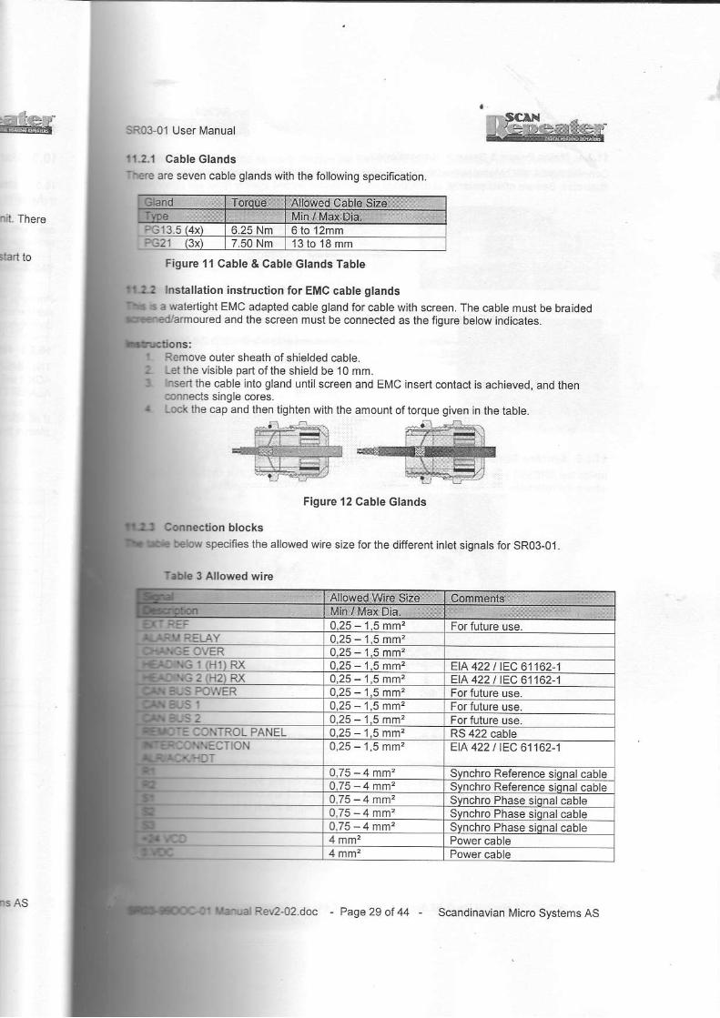
I Cable Glandsare seven erble glands with the following specification.
m There
la.l to Figure ll Cable & Cable Glands Table
hstallation instruction for EMC cable glandswatedight EI\,4C adapled cable gland for cable with screen. The cabte must be bra;ded
ured and the screen must be connecled as thefigure below indicates.
R€rnove outer sheath ofshielded cabte.l-el the visible pad ofihe shield be 10 mm.
ihe cable inlo gland untilscreen and EMC insert contact is achieved,and thensingle cores.
the cap and lhen tighten with the amount oftorque given in the table
Figure 12 Cable clands
blockssp€cfies the allowed wire size for the dlfterent intet signats for SR03-01_
3 Allowed wirE
ts ASRan242.doc Page 29 of 44 Scandinavian Micro Systems AS

SR03-01 User l\,4anual
11.2.4 Mains Power& Ground ConnectionsConnectthe 24 VDC [,{ains lothe 20 ampere miniature circuit breakef, aslhe tigure belowillustrates. geware of the polarity.
ttvpJ--l
t.zvpc l
Figure 13 24 VDC Power Connection.
Make sure the unit is grounded propetly through the l\IainGround Lug.
Figure '14 Main Ground-Lug
1 1.2.5 Synchro Signal Output ConnectionsInside the SR03-01 you will find the synchlo connection block for the Synch ro Output Signals
R2s2slNCRI
Figure l5 Synchro Signal Connection Block
11.2.6 Synchro SignalOutput Connections including the Repeater LightconnectedInside the SR03 01 you willfind the synchro conneclion blockforthe Synchro Output Signalswhere the reference R1,R2 and the phase signals 51, 52 and 53 are connected. As an option ilis possible to source the Repeater wilh an additional Lamp signalwhich is in phase with one ofthe reference sionals,
where the reference R1. R2 and the phase si 51, 52 and 53 are connected.
SR03-99DOC-01 [4anual Rev2-02.doc - Page 30 of zl4 - Scandinavian lvicro Systems AS

e'
,ain
bnals
SR0+01 lJser Manual
UTION: The lamp signal is relative the Reference signal. Selecting wrong Referencerelative the Lamp signalwill give 4 times as high voltage as wanted and Ite /arDp w,iltVedfy the lamp voltage before connecting the lamp wire to lhe repeater.
secondary lransformer load is 70 VA.
the transformer to the Synchro Connector as
16 Synchro Signal Connection Block lncl. Repeatet /amp transfomer illustratesRed lo Ri
RI LAMPS1 52 53 R2
l6 Synchro Signal Connection Block lncl. Repeater lamp transformer
faults and the retated heading errortt€t /een the lrechanical Repeater heading and the heading in SR03-01 /
mechanical repealer rotales in the reverse direction related to SR03-01 and lhe-exchange cables S1 and S3.aIl lhe mechanical repeaters.
stillis mismatch between the Mechanical Repealer headings followihe flow charlaDalstsbn ill|e of
ms AS I Manual Rev2-o2.doc - Page31 of,g - Scandinavian Micro SyslemsAs

SR0+01 User Manual
i/bw ed6 lrom @nne.tor s1 to s3Mde @trle lrom connEior 53 lo 51
change lhe gyo he.tinq /
mechan€l EPe6{s) d..toll@ lhe sde drecton 6
lvtore eU€ lrm @nnecld Rl io R2Mow @ble f'om @nnector Fu 10 R3
st rt'@ble mnEction faulf Po@due
I360X 180X s0x 36X
180
M@ @ble ftn @neclor Sl to 52MN cable fim conrecto. 52 io 53-Mow cable from @nrecio. 53 lo 51-
SRO199DOG01 Manual Rev242 doc - Page 32 ol 44 Scandinavian Micro Systems AS
SR0301 User Manual
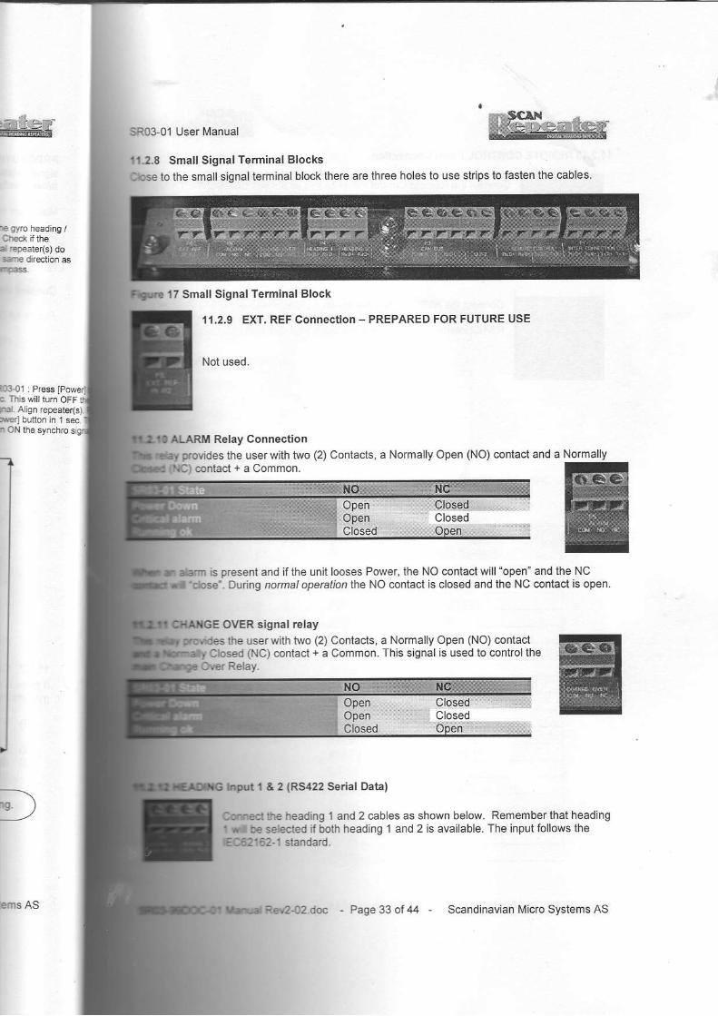
112.8 Small Signal Terminal Blocks
Cb6e lo the small signal terminal block thele aIe three holes to use slfips to fasten the cables.
l7 Smal l SignalTerminal Block
AI,ARM Relay Connection
Fovides the userwith two (2) Conlacts, a Normally Open (NO) conlacl and a Normallyaclcontact+aCommon
,I1.2.9 EXT. REF Connecuon _ PREPARED FOR FUTURE USE
Nol used.
b present and i f the unit looses Power, lhe NO coniactwi l l open"andlheNCtose'. Du dng ,ormal operatio, the NO contact is closed and the NC conlact is open.
OVER signal relaythe userwiih iwo (2) Contacts, a Normally Open (NO) conlact
Clos€d (NC) contact + a Common. This signal is used lo controllheot€. Relay.
le0rl & 2 {Rs422 Senal Data)
&n6dtlE heading 1 and 2 cables as shown below. Remember that headingI J bo s€bcted if both heading 1 and 2 is availabb. The input lollows theEEli@-l standard.
Closed
PMS AS Ra|r2.O2i& - Page 33 of 44 Scandinavian lvlicro Systems AS

SR03-01 User Manual
11.2.13 REMOTE CONTROL Panel connecdon
-.scrx||crcCle-r-
connectthe Remote Control Panelcables as shown. Connect the TX signalIrcm lf,e Controller Boatd with lhe RX signal to the Remote Control Panel.The Remote Conlrol Panel also requires 24V DC input.
11.2.14 NMEA OUPUT Serial Data connection
Connectthe NI\IEA serial chan.el for ALRyACK and/of HDT sentences tothe P1 (NTER CONNECIION) connection block. This is a fullduplexRS422 inierface and meels the 18C62162-1 & 1EC62162-2 specitication.
SR0199DOC 01 l\,'lanual Rev2-o2.doc - Page 34 of 44 Scandinavian llicro Systems AS

IE*f
I the TX signal
I (tuplexEc'fication,
User lvlanual
Technical Specifications
Approvals
I Specification
!l Volt Power InDut
OutputSignal
Prodtlces the reterence and phase Synchro Signals for allthe following
Gonfiguralion Types
- Page 35 ofzg - Scandinavian Micro Syslems ASInems AS
SR03,01 User l\ranual
Tokimek 1Tokimek 2
90x 50 Hz
ffiffi
90x 60 HzTokimek 3 360X 50 Hz
lqllmek 4 360X 60 HzIyEGA-tv 1 360X 50 Hz&lqgawa I 360X 50 HzYokogawa 2 360X 50 HzYokoqawa 3Yokogawa 4
360X 50 Hz360X 60 Hz
ltd,ili!i'iij'T,i""l""li## ;"#f ff l# l{ia"'l i:.".'J:i:" i:Hl, **,tr"'J""J::1Hi,i3"iffi;"j:;";;;10; ic^3"; nr,; vorase 86 v AC ins,ead or
12.2.3 Atarm Retay OutputThisretayprovides the userwith two (2) Conra(;l;n'"lmrry,ll,x.,p;a sn"*riill"i+i$#i#ffi#;it Hln i:JJ;#j :
The specification for tbe ajarm retay is shown in the lable betow.
Nole * : C_ustom configurabte (Defautt formao
l:::y^":_T .591691109i ?00 s, io.r"i,rt sora.: I;1".,""::^";.11",,.1r.y rci' "-"ri "i"p ib"?,lii o v ecr: 3::::,:l:1fl :; U: l lo u"c,' "",'!iJi ii"L"",i iVi",'.. Gear ratio: 1 lo 360 / 1 g"rri"ii"
"t"p. iDJilr[ lxl
11 11.-"1,:io,:**oary chanseover contror Rerayl?"H'3,"'J,",'il!::iiJ"?""J:JJ :f*llg*:::"iiil.asrackup - the primary sR03-oi hasi':1il:''T::.;i:ff["J::1fin"-"j:l1iiit9:1":jj-"1*it":'-i"-,"f5:li1lf,::'"3;lj'i:ii'Ag3 ;i't"J; ffyig"liTet ;n*:4ili:tl r! *il?i'.i'"i]l'"','"?"isi",,3,;! ;;::",X: ",?f1""!:.n;#
ffi;H:3,.:il J,i' J::t'':;i;,'r."Aff#l;operation wtone elro Coipiii.The specification for the change over conlrol relay ts gMen below.Table 6 Change OverControt Retav
Table 5 Alarm retay
110 VDC
i/.i SR0399DOC-01 tVanuat Rev2_02.doc _ Page 36 of44 , Scandinavian Micrc Syslems AS

*.
lj
rrtlntequal
ead of
r NormallyFr, theooatact is
BO1 has
ahgeovera
User Manual @ee'
SerialData Input (Heading I and 2)I data input is Optically Isolaied and designed for RS422. The input witl not be degradedb connecled. The specificaiion for IEC 61 1 62 1 is followed.
circuit is designed for operation with minimum differentiatinput voltage ofi2.0 Votts2.0 mAmp from lhe line atthat vollage.
$eriial Dala OutDutdata output channelfor the NMEA ALR and N[,4EA HDT fo ows the 1EC62.162-1 and
lSpecil ication
Specification
Specification of the Box
Input from Gyro Compass
lE Fdtocols shown in the table below.
ms ASPage 37 of 44 Scandinavian l\,licro Systems AS

SR03 01 Usef Nlanual
Noie *: Longiludina I waier speed inclusive ala|m flag.
Default proiocol setiing for serial inpul porl 1 . NMEA HEHDTDefault protocolsetling for serialinpul porl 2 : /DLE (notconfigurcd)
'12.5.2 NMEA PPLAN-interpreterThe PPLAN sentence has the possibilily to setup the auto decoding algorithm lo select betweenTRUE heading types or the |\,4AGNETIC heading types.
Table I NMEA PPLAN interpreter
Priorit\[f Comments r-.THS Noi valid 1{Hiohest) True headinqHEHDT Nol valid True headinoHCHDT 1(Hiqhesl ) Not valid [/aanetic Headinq--HDT Not valid Not valid True and lMaonetic--HDG 2 Not valid l\,4aqnetic Headinq.'HDtt4 3iLowest) Notval id Ivlaqnelic Headino
12.5.2.1 NMEA sentence TimeoutThe Nl\lEA senlence with highesl incoming pdority will source the synchro output signal. Headjngwith lower p ority will be disregarded.
12.5.2.1-1 Validation time for selecled heading sentence- I secondThe validation time for the heading wiih ihe highesl priority is one second. lfthe duration betweenoccurrences ofihis senience exceeds 1 second ihe next valid NIVEA heading wili be selecied.
12.5.2-1.2 Validation time for PPLAN sentence - 10 secondslflhe PPLAN sentence disappeals for more than 10 seconds the N[4EA PPlAN-intenretef willnot decode A/Vy NI\,lEA heading sentences.
12.5.3 Baud RateBaud Rale can be selected in the men as: 4800. 9600. 19200 or 38400 b/sec.
12.6 Synchro OutputSignals
12.6.1 Static Resolution & Accu€cyInternally the SR03-01 uses a 1 6,bit angu lar resolution but for the oLrtput stage it is reduced to 12bitto feed the analog 10 digilalconvefters. The output-sampling tate is I KHz. The practicatslaiicaccuracy is measured ior 1X signalio be betlefihan 10.4 degrees.
12.6.2 Rate of Tum {ROTIThe unit will drive ihe Synchro Repeaters with a maximum late ofium IROT) timited 1o 1200degrees per minute (20 degrees/second) independent ofgear ralio and reterence frequency.
12.6.3 Data Filter & Signal ProcessingSR03-01 accepts heading update lrequencies from as low as 1 updale per second and up to 50times per second for High Speed N[,4EA at 38400 bits/sec.
Since the input data resolution is normally 0.1 degree with NMEA 0183, which is equal to 36motor degrees at 360X - it is necessary lo lilterthe dala in order to creaie a smoolhty varying
.rsynchfo Signallo run the [,4echanical Synchro Repealers.
SR03-99DOC-01 l,,lanual Re\,2-02.doc - Page 38 of44 - Scandinavian f\licfo Systems AS

w
Fal. Heading
lrs€r Manual
Ged by sRolol is a Low Pass Average Filter with a Filter Length of 512 millisecond'
'L.g Ero/' / "schleppfehlei'r*s Average Filter creales a Dynamic Error(Lag Error or 'schleppfehlel') thai is
tothe Rate OfTurn (ROT).
3 has a constantdelay we can descnbe in lhe table belowthe lag elrol Theonly
itr catorlating ttre lag error is the rate of turn (RoT)
. iBi fr#fi ili i idF;!fi{:ij:,ii',1,i3?"'"1"r:::*'' H:li
lbn belweent selected.
rpreler will
llo 1200
l|d up 10 50
td to 36tlrarying
Educed to 12ractcal static
I Schleppfehler fot differcnt rate of tum
tSFlems AS Rev2{2.doc - Page3gof44 - Scandinavian Micro Systems AS

SR03 01 User l\,4anual
13 Maintenance
13.1 Dust t i l ierlnside the SR03 01 you willtind hvo fans for cooling the ampliiets. A dustlllter is installed attheair lntake to protect the SR03 01 from dusi inside. This filler needs 10 be ceaned when it gets
13.1.1 Specif icat ionFjlter material : Polyester foam 40 ppi (pores per inch).S i z e : 1 2 3 m m x 8 3 m m x 6 m m .
13.1.2 Dustf i l ter c leaning or exchangeWhen the flter gets contamjnated ofdust SR03 01 needs to be cleaned or exchanged with a new
13.1.2.1 IntervalThe cleaning of exchange inletuallorthe dust filtet is dependenl ofhow the envircnment aloundthe SR03 01. lfihe iemperalure alarm occurs check ihe duslfilterl
'13.1.2.2 Procedure Type 1
1. Rernove lhe liltercover from the SR03-01 by unscrewing four
3. f it is necessary io
unscrcwlwo scTews alihe top of the fanmodule. Then the fanmodule can be pul ledstraighl out. Unplugthe fan conneclor andnslal l the new fanmodule and filler.
Then ihe liller is ready
excnange0.
Figure 18
Remove filtercover
F'gure 19
Filter coverand filter re
Figure 20
Fan module rcmoved
' SR03-99DOC'01 lvlanual Rev2 02.doc Page 40 ol M Scandinavian Vlicro Systems AS

Plocedure - Type 2flbr cover from the SR03-01 by unscrew four screws.
Ed at theI gets
Figurc 2l Remove filter cover
rdy lo be deened or exchanged.tffl a new
I around
r*"IFs As
Figure 22 Filter removed
- Page41ol M - Scandinavian Mcro Systems AS

SR03-01 lJset [,4anual
L
J
Troubleshooting=;L;t l616r Panelwrl ld isprav a' s l-own when,r,. Controtip, eoard r-oso rs nrissing the Tr signal /
telegrams from ihe Local Control Panel'
tt n-emote controt panet is connected lo the system it
willindicate thailhe Controller Board (Ho,st) rs mrsslng
ir'," i* sgn"ilt"r"srrt" irom the Localconlrcl Panel
tt no-tn tne rr arc nx'rne" oetween conlro'ler Boa'd
\hosi) and lhe Remote or Local Conlr ol.Pane]t ]l-eiispdyi will inaicate inved blinking the lext "Displav
losl connectlon' shown belowii Remote Conlrol Panel rs conrefied lo the sysiem il
willild|cate thar rhe Cortro €r Board {Host) is mlsslnq
ii" r i"iq tri , r""gt".t trom tl'e Local Conlrol Panel
SR03-99DOC 01 l\4anual Rev2-02 doc Page 42 aI 44 Scandinavian l/licro Syslems AS
wof Guarantee
'@@M
r{lzzzaN
r.lkz-zaNf'JlrZ7aN:'Jl'zzaNf'{l'ZzaN:'{l'e7aN:'Jl,a7aN:'Jl,zzaN
f'll'azaN
F .-KIi signal /
|
e system al ID b missing IntrolPanel
I
aer Board IrEls, thel'Display
Is system rt I0 b missjng LntrolPanel
I
5..ll,a 5.flz4ZN 7aN;'.Jlza 5.Jlz4 ;'.Jlz4 ;5.Jlza
7415 745f 74N 74Ns
:'{lrzzaN:'{l,zzaN
r'JLzzaNr'JLz-ZN
SlL4 JlILZzaN ZN:'Jlrz-zaN
Certifrcate of Guarantee
ni3 iostunent is guaBnteed against defective materialssqtrrlanship, for a p€riod of24 months from the dateofdripment fiom Scandinavian Micro Systems.ofinstallation must be provided Scandinavian Miclo
S)ELms by complering and retuming the attached'IMPLEMENTATION of GUARANTEE CARD"
lhis guarantee Scandinavian Micro Systems will
4ir st its factory or replace this instrumeni or partsrhicll b€come defective in proper use and normal
d @., pmvided the defective instument or part isciriage pr€paid lo Scandinavian Micro Syslems
hbor and tmv€ling expenses are rot coveredtmder this guamntee.
fu rcpair and replacemenl parls. pdnted circuilrls should b€ directed to the local rcpresentative
Micro Systems or directly to us.type designation and serial number in all
all guarantee service witl be limited to
Fifted circuit boards or unils. A ll replacementailrit board and units will be charged to the
rcfimded to him upon receipt of cariageive parts, printed circuit boad and lmits.
Systems shall not in any way be liableial loss or damage occuning to any
st cture or building in which thisor temporarily located, nor to
i! conn€ction with the instrument.
D Systems AS - Page43 of 44 - Sc€ndinavian Micto Syslems AS

SR0301 User Manual
16 Sales & Support
For sales and technical support contact:
Scandinavian Micro Systems ASP.O. Box 155, TrollSsveien 36N-l411 Kolbotn, NORWAYPhone: +47.66a1.2740 | Fax +47.6680.8095E-mail: SalegoslalsyglqE-mail: suoport@scansvs-no
Scandinavian Micro Systems Inc.2800 Marina Mile Boulevard, Suite 101Fort Lauderdale, Florida 33312, USAPhone +1 954.583.5700/ Fax +1 9&.583.3699E-mail: [email protected]'l: Suppgl(os@lgyljg
4 r
$;SR03-99DOG0'1ManualRev2-o2.doc - Page44otM - Scandinavian Micro Syslems AS

Final-test for'SR03-01 Serial No. 103010120
Unit HW version and Se alno. SW versionBooster 35t07 #0122
Dynamic load on PCB.External Fanmodule.
NA
Controllef v1.3 #0126Requlator: TEN 12-241'1
v2.02
User lnterface v1.4 #0119 v2.02
uReoeatea tvoe and qeaa None. 50H2, 0/0-0volt. 1xHeadinq 1 Protocol: NI\4EA HEHDT. 48OO
. Default settin
Functional verification.User interface and l/O.
Unit ResultDisplav backliqhVconirast and dim. okArrcw and Enter Buttons WLED'S okPower Button WLED okAlarm Reset button WLED okVentilation fan and dustfilter. Air direction. OK
Headinq 1 input connection okHeadino 2 inout connection okRemote Control l/O connection okNMEA ALR serial Uo connection OK
cAN BUS l/O connection NAExteanal Ref. lnDut connection NAAlarm outout. Alarm {Connection C - NC) okAlarm outDut. No Alarm {Conneclion C - NC okChanqe Over output connection ok
Static ase and reference voltaTest conditions:
Mains inout voltaqe: 24VSvnchro Frcquencv, Reierence, Phase and gear: 50H2. 110V. 0 - 90V, 1xOutout Load: None
Measutements:
Deq.!nput
cu entRef.
Voltaqe 51-3 vollaqe S1-2 vollaqe S2-3 voltaqe0 1.8A 109.8 0.05 77,9 77.990 1 .8A 109.8 89.8 45.0 44.8120 '1.84 109 ,8 77 .8 0 . 1 0 77,9210 1 ,8A 109.8 44.9 89,9 44.9240 1 .8A 109 .8 77.8 77.9 0 . 1 4
- 330 1.8A '109.8 45.0 44.9 90,0
f, p.o. go" rss. nolaaveien 36N 1411 Kolborn, NORWAY
Phone: +47 6531.27]10 / Fa: +47.6630 3095
iscandinavian Micro systems AS Scandinavian Micro System6 Inc.1001 Sou$ And€wsArenue. Suite 120 /
FodLauderdale. Florlda 33316. USAPhon€ +1 954.523.3373 / Far +1 954 523.7157
o f 3E-marr sales(@scansvs.n
Document: FinaltesiSR03-01 Sno 103010120.doc ' . 1

4
\
. {
Setup for burnin and accuracy test on SR03-01.
24V DC Supply
PCTestanglegenerator
andcomparator
sR03-01
R'1-R2 Reierence 110V 50HzLoad
147ohm
100ohmstar
S1-S2€3 Phase 0 -90V 50Hz
JTestunit
RDC 19220Synchro
toMRU ROLL
Serial l/O
Scandihavian Micro Systems ASP.o. Box 155 TDlt,sveten 36N-141 1 Kolboin, NORWAY
Phone +47.66a1.tt40 / Fd +47 6330 3os5
Scandinavian Micro Systems Ine.1001 South Ande8 AEnue, Suiie 120 /
Fod Laudedalo. flonda 33316. USAPhone +1.9f4.523.43ft / Fd: +1-94,4 523.71t
DocumenliFinal-testSR0301Sno103010120.doc Paae:2o13

Accuracy test after >24 hours burnin.Date: 13.09.2007lvlodel: sR03-01Serlal No. '103010120
Ambient temo. 25ClntemaltemD.Mains voltaqe 24V DCCurrent consumption 24V 7.8AInout orotokoll NIMEA.9600lnput messaqe rate Tx / Sec. 1 0Head nq rotation Deo./l\,,1 n. 60Plot displav tvpe Delaved 8OutD!t load on Reference 147ohm rcsist veOutDut load on Phase 100ohm resist ve starGear ratio 1 xTested bv Knut Swertsen
Testresult for SR03-01 #103010120
0 2 5
0 l l
SCAND NAVIAN l,'1CFO SYSTEMS
r l i llU ilJll! uu \iliitrin,ltfl t l ftslll I '
' Scandinavian Micro Systems AS Scandinavian Micro Systems Inc.- P .O Eox 155, Tro lSsveen 36 1oo1southAndr€wsAvenu€, Sute 1201N,l41l Korboln NoRwAY Fon Laudedale Fo da33316 USA
Phon€: +47 66312740/ Far +47.6630 3095 Phone+19s4s23.3373/Fax+1954523.7157E-ma sa esascansvs no
Documenl: Final- iest SR03'01 Sno 103010120.doc Paoe: 3 of 3