SPYDER RS ROADSTER - Bombardier Recreational · PDF fileCALIFORNIA PROPOSITION65WARNING...
163
Original Instructions OPERATOR’S GUIDE 2014 SPYDER TM RS ROADSTER Includes Safety, Vehicle and Maintenance Information 219 001 223
Transcript of SPYDER RS ROADSTER - Bombardier Recreational · PDF fileCALIFORNIA PROPOSITION65WARNING...

Original Instructions
CALIFORNIA PROPOSITION 65 WARNING
WARNINGThis product contains or emits chemicals known to the state of California tocause cancer and birth defects or other reproductive harm.
In Canada, products are distributed by Bombardier Recreational Products Inc.
In USA, products are distributed by BRP US Inc.
This is a non-exhaustive list of trademarks that are the property of BombardierRecreational Products Inc. or its affiliates:
4-TECTM Rotax® SpyderTM XPSTM
rmo2014-001 en
®™ and the BRP logo are trademarks of Bombardier Recreational Products Inc. or its affiliates.
©2013 Bombardier Recreational Products Inc. and BRP US Inc. All rights reserved.
SPYD
ER R
S20
13
®™ AND THE BRP LOGO ARE TRADEMARKS OF BOMBARDIER RECREATIONAL PRODUCTS INC. OR ITS AFFILIATES.©2012 BOMBARDIER RECREATIONAL PRODUCTS INC. ALL RIGHTS RESERVED. PRINTED IN CANADA.
219 000 981 CA
OPERATOR’S GUIDE, SPYDER RS / ENGLISHGUIDE DU CONDUCTEUR, SPYDER RS / ANGLAIS
FAIT AU / MADE IN CANADA U/M:P.C.
2 1 9 0 0 0 9 8 1
219 001 223 CA
OPERATOR’S GUIDE, SPYDER RS / ENGLISHGUIDE DU CONDUCTEUR, SPYDER RS / ANGLAIS
FAIT AU / MADE IN CANADA U/M:P.C.
®™ AND THE BRP LOGO ARE TRADEMARKS OF BOMBARDIER RECREATIONAL PRODUCTS INC. OR ITS AFFILIATES.©2013 BOMBARDIER RECREATIONAL PRODUCTS INC. ALL RIGHTS RESERVED. PRINTED IN CANADA.
OPERATOR’SGUIDE
2014
SPYDERTM RS
ROADSTER
Includes Safety, Vehicleand Maintenance Information
2 1 9 0 0 1 2 2 3
SPYD
ER R
S20
14

CALIFORNIA PROPOSITION 65 WARNING
WARNINGThis product contains or emits chemicals known to the state of California tocause cancer and birth defects or other reproductive harm.
In Canada, products are distributed by Bombardier Recreational Products Inc.
In USA, products are distributed by BRP US Inc.
This is a non-exhaustive list of trademarks that are the property of BombardierRecreational Products Inc. or its affiliates:
4-TECTM Rotax® SpyderTM XPSTM
rmo2014-001 en
®™ and the BRP logo are trademarks of Bombardier Recreational Products Inc. or its affiliates.
©2013 Bombardier Recreational Products Inc. and BRP US Inc. All rights reserved.

FOREWORD
DeutschDieses Handbuch ist möglicherweise in Ihrer Landesspracheverfügbar. Bitte wenden Sie sich an Ihren Händler oder besuchen Sie:www.operatorsguide.brp.com.
EnglishThis guide may be available in your language. Check with your dealer orgo to: www.operatorsguide.brp.com.
EspañolEs posible que este manual esté disponible en su idioma. Consulte a sudistribuidor o visite: www.operatorsguide.brp.com.
FrançaisCe guide peut être disponible dans votre langue. Vérifier avec votreconcessionaire ou aller à: www.operatorsguide.brp.com.
日本語
このガイドは、言語によって翻訳版が用意されています。.
ディーラーに問い合わせるか、次のアドレスでご確認ください:
www.operatorsguide.brp.com.
NederlandsDeze handleiding kan beschikbaar zijn in uw taal. Vraag het aan uw dealerof ga naar: www.operatorsguide.brp.com.
NorskDenne boken kan finnes tilgjengelig på ditt eget språk. Kontakt dinforhandler eller gå til: www.operatorsguide.brp.com.
PortuguêsEste manual pode estar disponível em seu idioma. Fale com suaconcessionária ou visite o site: www.operatorsguide.brp.com.
SuomiKäyttöohjekirja voi olla saatavissa omalla kielelläsi. Tarkista jälleenmyyjältätai käy osoitteessa: www.operatorsguide.brp.com
SvenskaDenna bok kan finnas tillgänglig på ditt språk. Kontakta din återförsäljareeller gå till: www.operatorsguide.brp.com.
Congratulations on your purchase of anew CAN-AM™ Roadster. It is backedby the Bombardier RecreationalProducts Inc. (BRP) warranty and anetwork of authorized dealers readyto provide the parts, service or acces-sories you may require.
Your dealer is committed to your sat-isfaction. He has taken training to per-form the initial set-up and inspection ofyour roadster before you took posses-sion.
At delivery, you were informed of thewarranty coverage and signed thePREDELIVERY CHECK LIST to ensureyour new vehicle was prepared to yourentire satisfaction.
Know Before you Go
For your safety and the safety of pas-sengers and bystanders, read the fol-lowing sections before you operatethe Spyder roadster:
– GENERAL PRECAUTIONS– VEHICLE INFORMATION– SAFE OPERATING INSTRUCTIONS– PRE-RIDE INSPECTION.
Experienced motorcyclists should payspecial attention to the WHAT'S DIF-FERENT ABOUT THE SYPDER ROAD-STER subsection.
Safety Messages
The types of safety messages, whatthey look like and how they are used inthis guide are explained as follows:
_______________ 1

FOREWORD
The safety alert symbol indicatesa potential injury hazard.
WARNINGIndicates a potential hazard, if notavoided, could result in serious in-jury or death.
CAUTION Indicates a hazardsituation which, if not avoided,could result in minor or moderateinjury.
NOTICE Indicates an instructionwhich, if not followed, could se-verely damage vehicle componentsor other property.
About this Operator'sGuide
This Operator's Guide was written inNorth America in a right-lane drivingenvironment. Please adapt your ap-plication of these maneuvers to yourjurisdiction and rules of the road.
In this Operator's Guide, the wordmotorcycle typically refers to atwo-wheeled motorcycle.
This Operator's Guide is for both theSM5 (manual transmission) and theSE5 (semi-automatic transmission)Spyder roadster models. All text ap-plies to both except for those itemsspecified as "SM5 Model" or "SE5Model".
Keep this Operator's Guide in the frontstorage compartment so that you canrefer to it for things such as mainte-nance, road side repairs and instruct-ing others.
If you want to view and/or printan extra copy of your Operator'sGuide, simply visit the following web-site:www.operatorsguide.brp.com.
The informations contained in this doc-ument are correct at the time of publi-cation. BRP, however, maintains a pol-icy of continuous improvement of its
products without imposing upon itselfany obligation to install them on prod-ucts previously manufactured. Dueto late changes, some differences be-tween the manufactured product andthe descriptions and/or specificationsin this guide may occur. BRP reservesthe right at any time to discontinue orchange specifications, designs, fea-tures, models or equipment withoutincurring any obligation upon itself.
This Operator's Guide and the SAFETYDVD video should remain with the ve-hicle when it is sold.
Refer to Other Sources ofInformation
In addition to reading this Operator'sGuide, you should read the Safety Cardon the vehicle and watch the SAFETYDVD video.
If possible, take a training coursethat is specifically designed for theSpyder roadster. Check our websiteat www.can-am.brp.com for moreinformation about upcoming trainingcourse availability. If you cannot takea training course specifically designedfor the Spyder roadster, it is a good ideato take a motorcycle training course,since some of the skills required aresimilar and information about man-aging risk on the road is taught andsimilarly applies to riding your Spyderroadster.
Acknowledgment
BRP wishes to thank the MotorcycleSafety Foundation (MSF) for givingpermission to BRP to use their mate-rial related to street motorcycle safetyfound in this Operator's Guide.
The MSF is an internationally recog-nized not for profit foundation andis supported by motorcycle manu-facturers. It provides training, toolsand partnerships to the motorcyclesafety community. Visit its websiteat:www.msf-usa.org.
2 _______________

TABLE OF CONTENTS
FOREWORD ... . . . . . . . . . . . . . . . . . . . . . . . . . . . . . . . . . . . . . . . . . . . . . . . . . . . . . . . . . . . . . . . . . . . . . . . 1Know Before you Go.. . . . . . . . . . . . . . . . . . . . . . . . . . . . . . . . . . . . . . . . . . . . . . . . . . . . . . . . . . . . 1Safety Messages.. . . . . . . . . . . . . . . . . . . . . . . . . . . . . . . . . . . . . . . . . . . . . . . . . . . . . . . . . . . . . . . . 1About this Operator's Guide . . . . . . . . . . . . . . . . . . . . . . . . . . . . . . . . . . . . . . . . . . . . . . . . . . . . 2Refer to Other Sources of Information .. . . . . . . . . . . . . . . . . . . . . . . . . . . . . . . . . . . . . . . . 2Acknowledgment . . . . . . . . . . . . . . . . . . . . . . . . . . . . . . . . . . . . . . . . . . . . . . . . . . . . . . . . . . . . . . . . 2
GENERAL PRECAUTIONS... . . . . . . . . . . . . . . . . . . . . . . . . . . . . . . . . . . . . . . . . . . . . . . . . . . . . . . . 7Avoid Carbon Monoxide Poisoning .. . . . . . . . . . . . . . . . . . . . . . . . . . . . . . . . . . . . . . . . . . . . 7Avoid Gasoline Fires and Other Hazards . . . . . . . . . . . . . . . . . . . . . . . . . . . . . . . . . . . . . . . 7Avoid Burns from Hot Parts .. . . . . . . . . . . . . . . . . . . . . . . . . . . . . . . . . . . . . . . . . . . . . . . . . . . . 7Accessories and Modifications .. . . . . . . . . . . . . . . . . . . . . . . . . . . . . . . . . . . . . . . . . . . . . . . . 7
VEHICLE INFORMATION
PRIMARY CONTROLS . .. . . . . . . . . . . . . . . . . . . . . . . . . . . . . . . . . . . . . . . . . . . . . . . . . . . . . . . . . . . 101) Handlebar . . . . . . . . . . . . . . . . . . . . . . . . . . . . . . . . . . . . . . . . . . . . . . . . . . . . . . . . . . . . . . . . . . . . . 122) Throttle .. . . . . . . . . . . . . . . . . . . . . . . . . . . . . . . . . . . . . . . . . . . . . . . . . . . . . . . . . . . . . . . . . . . . . . . 123) Clutch Lever (SM5 Model). . . . . . . . . . . . . . . . . . . . . . . . . . . . . . . . . . . . . . . . . . . . . . . . . . . 124) Gearshift Lever (SM5 Model). . . . . . . . . . . . . . . . . . . . . . . . . . . . . . . . . . . . . . . . . . . . . . . . 135) Gearshift Selector (SE5 Model) . . . . . . . . . . . . . . . . . . . . . . . . . . . . . . . . . . . . . . . . . . . . . 136) Brake Pedal . . . . . . . . . . . . . . . . . . . . . . . . . . . . . . . . . . . . . . . . . . . . . . . . . . . . . . . . . . . . . . . . . . . 147) Parking Brake Pedal . . . . . . . . . . . . . . . . . . . . . . . . . . . . . . . . . . . . . . . . . . . . . . . . . . . . . . . . . . 14
SECONDARY CONTROLS. .. . . . . . . . . . . . . . . . . . . . . . . . . . . . . . . . . . . . . . . . . . . . . . . . . . . . . . . 151) Ignition Switch.. . . . . . . . . . . . . . . . . . . . . . . . . . . . . . . . . . . . . . . . . . . . . . . . . . . . . . . . . . . . . . . 162) Engine Start Button . . . . . . . . . . . . . . . . . . . . . . . . . . . . . . . . . . . . . . . . . . . . . . . . . . . . . . . . . . 163) Engine Stop Switch . . . . . . . . . . . . . . . . . . . . . . . . . . . . . . . . . . . . . . . . . . . . . . . . . . . . . . . . . . 164) Hazard Warning Switch . . . . . . . . . . . . . . . . . . . . . . . . . . . . . . . . . . . . . . . . . . . . . . . . . . . . . . 165) Cruise Control Switch (RS-S Models Only) . . . . . . . . . . . . . . . . . . . . . . . . . . . . . . . . . 166) Headlights Switch .. . . . . . . . . . . . . . . . . . . . . . . . . . . . . . . . . . . . . . . . . . . . . . . . . . . . . . . . . . . 197) Turn Signal Button .. . . . . . . . . . . . . . . . . . . . . . . . . . . . . . . . . . . . . . . . . . . . . . . . . . . . . . . . . . . 198) Horn Button . . . . . . . . . . . . . . . . . . . . . . . . . . . . . . . . . . . . . . . . . . . . . . . . . . . . . . . . . . . . . . . . . . . 199) RECC (Roadster Electronic Command Center) . . . . . . . . . . . . . . . . . . . . . . . . . . . . 1910) Reverse Button . .. . . . . . . . . . . . . . . . . . . . . . . . . . . . . . . . . . . . . . . . . . . . . . . . . . . . . . . . . . . 20
MULTIFUNCTION GAUGE CLUSTER (BASE MODEL) .. . . . . . . . . . . . . . . . . . . . . . . 21Description . . . . . . . . . . . . . . . . . . . . . . . . . . . . . . . . . . . . . . . . . . . . . . . . . . . . . . . . . . . . . . . . . . . . . . 21Startup and Shutdown. . .. . . . . . . . . . . . . . . . . . . . . . . . . . . . . . . . . . . . . . . . . . . . . . . . . . . . . . . 23Digital Display Information . .. . . . . . . . . . . . . . . . . . . . . . . . . . . . . . . . . . . . . . . . . . . . . . . . . . . 23Display Settings . .. . . . . . . . . . . . . . . . . . . . . . . . . . . . . . . . . . . . . . . . . . . . . . . . . . . . . . . . . . . . . . . 23
MULTIFUNCTION GAUGE (RS-S MODEL). . . . . . . . . . . . . . . . . . . . . . . . . . . . . . . . . . . . . . 25Description . . . . . . . . . . . . . . . . . . . . . . . . . . . . . . . . . . . . . . . . . . . . . . . . . . . . . . . . . . . . . . . . . . . . . . 25Multifunction Gauge Startup Information . .. . . . . . . . . . . . . . . . . . . . . . . . . . . . . . . . . . . 27Digital Display Description . .. . . . . . . . . . . . . . . . . . . . . . . . . . . . . . . . . . . . . . . . . . . . . . . . . . . 27Navigating in the Digital Display.. . . . . . . . . . . . . . . . . . . . . . . . . . . . . . . . . . . . . . . . . . . . . . . 28Category Icon Screen Description . .. . . . . . . . . . . . . . . . . . . . . . . . . . . . . . . . . . . . . . . . . . . 29
_______________ 3

TABLE OF CONTENTS
EQUIPMENT. .. . . . . . . . . . . . . . . . . . . . . . . . . . . . . . . . . . . . . . . . . . . . . . . . . . . . . . . . . . . . . . . . . . . . . . . 32Mirrors . . . . . . . . . . . . . . . . . . . . . . . . . . . . . . . . . . . . . . . . . . . . . . . . . . . . . . . . . . . . . . . . . . . . . . . . . . . 32Locking the Handlebar . . . . . . . . . . . . . . . . . . . . . . . . . . . . . . . . . . . . . . . . . . . . . . . . . . . . . . . . . . 32Front Storage Compartment . . . . . . . . . . . . . . . . . . . . . . . . . . . . . . . . . . . . . . . . . . . . . . . . . . . 32Tool Kit . . . . . . . . . . . . . . . . . . . . . . . . . . . . . . . . . . . . . . . . . . . . . . . . . . . . . . . . . . . . . . . . . . . . . . . . . . . 32Operator's Guide .. . . . . . . . . . . . . . . . . . . . . . . . . . . . . . . . . . . . . . . . . . . . . . . . . . . . . . . . . . . . . . . 33Seat . . . . . . . . . . . . . . . . . . . . . . . . . . . . . . . . . . . . . . . . . . . . . . . . . . . . . . . . . . . . . . . . . . . . . . . . . . . . . . 33Body Panels . .. . . . . . . . . . . . . . . . . . . . . . . . . . . . . . . . . . . . . . . . . . . . . . . . . . . . . . . . . . . . . . . . . . . 33
BASIC PROCEDURES . . .. . . . . . . . . . . . . . . . . . . . . . . . . . . . . . . . . . . . . . . . . . . . . . . . . . . . . . . . . . . 37Starting and Stopping the Engine . . . . . . . . . . . . . . . . . . . . . . . . . . . . . . . . . . . . . . . . . . . . . . 37Operating in Reverse . . . . . . . . . . . . . . . . . . . . . . . . . . . . . . . . . . . . . . . . . . . . . . . . . . . . . . . . . . . 39Operating During Break-In. . . . . . . . . . . . . . . . . . . . . . . . . . . . . . . . . . . . . . . . . . . . . . . . . . . . . . 39Fueling . . . . . . . . . . . . . . . . . . . . . . . . . . . . . . . . . . . . . . . . . . . . . . . . . . . . . . . . . . . . . . . . . . . . . . . . . . . 40Adjusting Suspension (RS-S Models Only) . . . . . . . . . . . . . . . . . . . . . . . . . . . . . . . . . . . 41
SAFE OPERATING INSTRUCTIONS
WHAT'S DIFFERENT ABOUT THE SPYDER ROADSTER . . .. . . . . . . . . . . . . . . . . . . 44Stability . . . . . . . . . . . . . . . . . . . . . . . . . . . . . . . . . . . . . . . . . . . . . . . . . . . . . . . . . . . . . . . . . . . . . . . . . . 44Response to Road Conditions. . . . . . . . . . . . . . . . . . . . . . . . . . . . . . . . . . . . . . . . . . . . . . . . . . 44Brake Pedal . . . . . . . . . . . . . . . . . . . . . . . . . . . . . . . . . . . . . . . . . . . . . . . . . . . . . . . . . . . . . . . . . . . . . . 44Parking Brake .. . . . . . . . . . . . . . . . . . . . . . . . . . . . . . . . . . . . . . . . . . . . . . . . . . . . . . . . . . . . . . . . . . . 44Steering . . . . . . . . . . . . . . . . . . . . . . . . . . . . . . . . . . . . . . . . . . . . . . . . . . . . . . . . . . . . . . . . . . . . . . . . . . 44Width. .. . . . . . . . . . . . . . . . . . . . . . . . . . . . . . . . . . . . . . . . . . . . . . . . . . . . . . . . . . . . . . . . . . . . . . . . . . . 45Reverse . . . . . . . . . . . . . . . . . . . . . . . . . . . . . . . . . . . . . . . . . . . . . . . . . . . . . . . . . . . . . . . . . . . . . . . . . . 45Driver's License and Local Laws. . . . . . . . . . . . . . . . . . . . . . . . . . . . . . . . . . . . . . . . . . . . . . . 45
DRIVING AID TECHNOLOGIES . . . . . . . . . . . . . . . . . . . . . . . . . . . . . . . . . . . . . . . . . . . . . . . . . . . 46Vehicle Stability System (VSS) . .. . . . . . . . . . . . . . . . . . . . . . . . . . . . . . . . . . . . . . . . . . . . . . . 46Dynamic Power Steering (DPS) .. . . . . . . . . . . . . . . . . . . . . . . . . . . . . . . . . . . . . . . . . . . . . . . 47
UNDERSTANDING RISK ON THE ROAD .. . . . . . . . . . . . . . . . . . . . . . . . . . . . . . . . . . . . . . . 48Type of Vehicle . . . . . . . . . . . . . . . . . . . . . . . . . . . . . . . . . . . . . . . . . . . . . . . . . . . . . . . . . . . . . . . . . . 48Operator Skills and Judgment. . . . . . . . . . . . . . . . . . . . . . . . . . . . . . . . . . . . . . . . . . . . . . . . . . 48Rider Condition . . . . . . . . . . . . . . . . . . . . . . . . . . . . . . . . . . . . . . . . . . . . . . . . . . . . . . . . . . . . . . . . . . 48Vehicle Condition.. . . . . . . . . . . . . . . . . . . . . . . . . . . . . . . . . . . . . . . . . . . . . . . . . . . . . . . . . . . . . . . 49Road and Weather Conditions . .. . . . . . . . . . . . . . . . . . . . . . . . . . . . . . . . . . . . . . . . . . . . . . . 49
RIDING GEAR .. . . . . . . . . . . . . . . . . . . . . . . . . . . . . . . . . . . . . . . . . . . . . . . . . . . . . . . . . . . . . . . . . . . . . . 50Helmets. . . . . . . . . . . . . . . . . . . . . . . . . . . . . . . . . . . . . . . . . . . . . . . . . . . . . . . . . . . . . . . . . . . . . . . . . . 50Other Riding Gear . . . . . . . . . . . . . . . . . . . . . . . . . . . . . . . . . . . . . . . . . . . . . . . . . . . . . . . . . . . . . . . 50
REQUIRED RIDING SKILLS AND PRACTICE EXERCISES . .. . . . . . . . . . . . . . . . . . . 53Choosing a Practice Area . . . . . . . . . . . . . . . . . . . . . . . . . . . . . . . . . . . . . . . . . . . . . . . . . . . . . . . 53Preparing to Ride .. . . . . . . . . . . . . . . . . . . . . . . . . . . . . . . . . . . . . . . . . . . . . . . . . . . . . . . . . . . . . . . 54Riding Posture. . . . . . . . . . . . . . . . . . . . . . . . . . . . . . . . . . . . . . . . . . . . . . . . . . . . . . . . . . . . . . . . . . . 54Practice Exercises (SM5 Model) . . . . . . . . . . . . . . . . . . . . . . . . . . . . . . . . . . . . . . . . . . . . . . . 54Practice Exercises (SE5 Model) . . . . . . . . . . . . . . . . . . . . . . . . . . . . . . . . . . . . . . . . . . . . . . . . 63Developing Advanced Riding Skills .. . . . . . . . . . . . . . . . . . . . . . . . . . . . . . . . . . . . . . . . . . . 70
4 _______________

TABLE OF CONTENTS
STREET STRATEGIES. . .. . . . . . . . . . . . . . . . . . . . . . . . . . . . . . . . . . . . . . . . . . . . . . . . . . . . . . . . . . . 71Plan your Trip .. . . . . . . . . . . . . . . . . . . . . . . . . . . . . . . . . . . . . . . . . . . . . . . . . . . . . . . . . . . . . . . . . . . 71Defensive Riding .. . . . . . . . . . . . . . . . . . . . . . . . . . . . . . . . . . . . . . . . . . . . . . . . . . . . . . . . . . . . . . . 71Being Visible . .. . . . . . . . . . . . . . . . . . . . . . . . . . . . . . . . . . . . . . . . . . . . . . . . . . . . . . . . . . . . . . . . . . . 72Lane Position .. . . . . . . . . . . . . . . . . . . . . . . . . . . . . . . . . . . . . . . . . . . . . . . . . . . . . . . . . . . . . . . . . . . 73Common Riding Situations . .. . . . . . . . . . . . . . . . . . . . . . . . . . . . . . . . . . . . . . . . . . . . . . . . . . . 73Road Conditions and Hazards . . . . . . . . . . . . . . . . . . . . . . . . . . . . . . . . . . . . . . . . . . . . . . . . . . 76On-Road Emergencies . .. . . . . . . . . . . . . . . . . . . . . . . . . . . . . . . . . . . . . . . . . . . . . . . . . . . . . . . 77Tire Failure . . . . . . . . . . . . . . . . . . . . . . . . . . . . . . . . . . . . . . . . . . . . . . . . . . . . . . . . . . . . . . . . . . . . . . . 77
CARRYING A PASSENGER OR CARGO ... . . . . . . . . . . . . . . . . . . . . . . . . . . . . . . . . . . . . . . 79Weight Limits.. . . . . . . . . . . . . . . . . . . . . . . . . . . . . . . . . . . . . . . . . . . . . . . . . . . . . . . . . . . . . . . . . . . 79Operating with Extra Weight . . . . . . . . . . . . . . . . . . . . . . . . . . . . . . . . . . . . . . . . . . . . . . . . . . . 79Carrying a Passenger . . . . . . . . . . . . . . . . . . . . . . . . . . . . . . . . . . . . . . . . . . . . . . . . . . . . . . . . . . . 79Where to Store Cargo. . . . . . . . . . . . . . . . . . . . . . . . . . . . . . . . . . . . . . . . . . . . . . . . . . . . . . . . . . . 80No Towing . . . . . . . . . . . . . . . . . . . . . . . . . . . . . . . . . . . . . . . . . . . . . . . . . . . . . . . . . . . . . . . . . . . . . . . 80
KNOWLEDGE SELF-TEST . .. . . . . . . . . . . . . . . . . . . . . . . . . . . . . . . . . . . . . . . . . . . . . . . . . . . . . . . 81Questionnaire . . . . . . . . . . . . . . . . . . . . . . . . . . . . . . . . . . . . . . . . . . . . . . . . . . . . . . . . . . . . . . . . . . . 81Answers . .. . . . . . . . . . . . . . . . . . . . . . . . . . . . . . . . . . . . . . . . . . . . . . . . . . . . . . . . . . . . . . . . . . . . . . . 83
SAFETY INFORMATION ON THE VEHICLE . .. . . . . . . . . . . . . . . . . . . . . . . . . . . . . . . . . . . 85Hang Tag . .. . . . . . . . . . . . . . . . . . . . . . . . . . . . . . . . . . . . . . . . . . . . . . . . . . . . . . . . . . . . . . . . . . . . . . . 85Safety Card . . . . . . . . . . . . . . . . . . . . . . . . . . . . . . . . . . . . . . . . . . . . . . . . . . . . . . . . . . . . . . . . . . . . . . 86Safety Labels .. . . . . . . . . . . . . . . . . . . . . . . . . . . . . . . . . . . . . . . . . . . . . . . . . . . . . . . . . . . . . . . . . . . 87
REPORTING SAFETY DEFECTS . . .. . . . . . . . . . . . . . . . . . . . . . . . . . . . . . . . . . . . . . . . . . . . . . . 90
PRE-RIDE INSPECTION
PRE-RIDE CHECKLIST. . .. . . . . . . . . . . . . . . . . . . . . . . . . . . . . . . . . . . . . . . . . . . . . . . . . . . . . . . . . . . 92
MAINTENANCE
MAINTENANCE SCHEDULE . . .. . . . . . . . . . . . . . . . . . . . . . . . . . . . . . . . . . . . . . . . . . . . . . . . . . . 94
BREAK-IN INSPECTION .. . . . . . . . . . . . . . . . . . . . . . . . . . . . . . . . . . . . . . . . . . . . . . . . . . . . . . . . . . 99
MAINTENANCE PROCEDURES . . .. . . . . . . . . . . . . . . . . . . . . . . . . . . . . . . . . . . . . . . . . . . . . 100Wheels and Tires .. . . . . . . . . . . . . . . . . . . . . . . . . . . . . . . . . . . . . . . . . . . . . . . . . . . . . . . . . . . . . 100Drive Belt .. . . . . . . . . . . . . . . . . . . . . . . . . . . . . . . . . . . . . . . . . . . . . . . . . . . . . . . . . . . . . . . . . . . . . 101Engine Oil . . . . . . . . . . . . . . . . . . . . . . . . . . . . . . . . . . . . . . . . . . . . . . . . . . . . . . . . . . . . . . . . . . . . . . 103Engine Oil Filter . . . . . . . . . . . . . . . . . . . . . . . . . . . . . . . . . . . . . . . . . . . . . . . . . . . . . . . . . . . . . . . 106HCM Oil Filter (SE5 Model). . . . . . . . . . . . . . . . . . . . . . . . . . . . . . . . . . . . . . . . . . . . . . . . . . . 106Engine Coolant . . . . . . . . . . . . . . . . . . . . . . . . . . . . . . . . . . . . . . . . . . . . . . . . . . . . . . . . . . . . . . . . 107Brakes.. . . . . . . . . . . . . . . . . . . . . . . . . . . . . . . . . . . . . . . . . . . . . . . . . . . . . . . . . . . . . . . . . . . . . . . . . 108Battery . . . . . . . . . . . . . . . . . . . . . . . . . . . . . . . . . . . . . . . . . . . . . . . . . . . . . . . . . . . . . . . . . . . . . . . . . 110Clutch Fluid (SM5 Model). . . . . . . . . . . . . . . . . . . . . . . . . . . . . . . . . . . . . . . . . . . . . . . . . . . . . 111Headlights . . . . . . . . . . . . . . . . . . . . . . . . . . . . . . . . . . . . . . . . . . . . . . . . . . . . . . . . . . . . . . . . . . . . . 112
VEHICLE CARE . . .. . . . . . . . . . . . . . . . . . . . . . . . . . . . . . . . . . . . . . . . . . . . . . . . . . . . . . . . . . . . . . . . . 113Vehicle Cleaning. .. . . . . . . . . . . . . . . . . . . . . . . . . . . . . . . . . . . . . . . . . . . . . . . . . . . . . . . . . . . . . 113
_______________ 5

TABLE OF CONTENTS
VEHICLE CARE (cont’d)Vehicle Protection. . . . . . . . . . . . . . . . . . . . . . . . . . . . . . . . . . . . . . . . . . . . . . . . . . . . . . . . . . . . . 113
STORAGE AND PRESEASON PREPARATION.. .. . . . . . . . . . . . . . . . . . . . . . . . . . . . . 114Storage. . . . . . . . . . . . . . . . . . . . . . . . . . . . . . . . . . . . . . . . . . . . . . . . . . . . . . . . . . . . . . . . . . . . . . . . . 114Preseason Preparation . .. . . . . . . . . . . . . . . . . . . . . . . . . . . . . . . . . . . . . . . . . . . . . . . . . . . . . 114
ROAD SIDE REPAIRS
DIAGNOSTIC GUIDELINES . . . . . . . . . . . . . . . . . . . . . . . . . . . . . . . . . . . . . . . . . . . . . . . . . . . . . 116Will not Shift into First Gear (SM5 Model). . . . . . . . . . . . . . . . . . . . . . . . . . . . . . . . . . . 116Will not Shift into Neutral (SE5 Model) . . . . . . . . . . . . . . . . . . . . . . . . . . . . . . . . . . . . . . 116Will not Shift (SE5 Model) . . . . . . . . . . . . . . . . . . . . . . . . . . . . . . . . . . . . . . . . . . . . . . . . . . . . 116Engine will not Start. . . . . . . . . . . . . . . . . . . . . . . . . . . . . . . . . . . . . . . . . . . . . . . . . . . . . . . . . . . 116
MESSAGES IN MULTIFUNCTION GAUGE ... . . . . . . . . . . . . . . . . . . . . . . . . . . . . . . . . 117
WHAT TO DO IN THE FOLLOWING CIRCUMSTANCES . . . . . . . . . . . . . . . . . . . . . 122Lost Keys .. . . . . . . . . . . . . . . . . . . . . . . . . . . . . . . . . . . . . . . . . . . . . . . . . . . . . . . . . . . . . . . . . . . . . 122Flat Tire. . . . . . . . . . . . . . . . . . . . . . . . . . . . . . . . . . . . . . . . . . . . . . . . . . . . . . . . . . . . . . . . . . . . . . . . . 122Dead Battery. .. . . . . . . . . . . . . . . . . . . . . . . . . . . . . . . . . . . . . . . . . . . . . . . . . . . . . . . . . . . . . . . . . 122
HOW TO REPLACE FUSES AND LIGHTS.. . . . . . . . . . . . . . . . . . . . . . . . . . . . . . . . . . . . . 124Fuses. .. . . . . . . . . . . . . . . . . . . . . . . . . . . . . . . . . . . . . . . . . . . . . . . . . . . . . . . . . . . . . . . . . . . . . . . . . 124Lights. .. . . . . . . . . . . . . . . . . . . . . . . . . . . . . . . . . . . . . . . . . . . . . . . . . . . . . . . . . . . . . . . . . . . . . . . . . 126
TRANSPORTING THE VEHICLE . . .. . . . . . . . . . . . . . . . . . . . . . . . . . . . . . . . . . . . . . . . . . . . . 132
TECHNICAL INFORMATION
VEHICLE IDENTIFICATION .. . . . . . . . . . . . . . . . . . . . . . . . . . . . . . . . . . . . . . . . . . . . . . . . . . . . . 136Vehicle Identification Number. . . . . . . . . . . . . . . . . . . . . . . . . . . . . . . . . . . . . . . . . . . . . . . . 136Engine Identification Number . . . . . . . . . . . . . . . . . . . . . . . . . . . . . . . . . . . . . . . . . . . . . . . . 136EPA Compliance Label (USA) . . . . . . . . . . . . . . . . . . . . . . . . . . . . . . . . . . . . . . . . . . . . . . . . 136
SPECIFICATIONS .. . . . . . . . . . . . . . . . . . . . . . . . . . . . . . . . . . . . . . . . . . . . . . . . . . . . . . . . . . . . . . . . 137
WARRANTY
BRP LIMITED WARRANTY — USA AND CANADA: 2014 Can-Am® SPYDER®
ROADSTER . . .. . . . . . . . . . . . . . . . . . . . . . . . . . . . . . . . . . . . . . . . . . . . . . . . . . . . . . . . . . . . . . . . . . . . . 144
BRP LIMITED WARRANTY OUTSIDE USA AND CANADA: 2014 Can-Am™SPYDERTM ROADSTER .. . . . . . . . . . . . . . . . . . . . . . . . . . . . . . . . . . . . . . . . . . . . . . . . . . . . . . . . . 149
CUSTOMER INFORMATION
PRIVACY INFORMATION .. .. . . . . . . . . . . . . . . . . . . . . . . . . . . . . . . . . . . . . . . . . . . . . . . . . . . . . 156
CHANGE OF ADDRESS/OWNERSHIP. . . . . . . . . . . . . . . . . . . . . . . . . . . . . . . . . . . . . . . . . 157
6 _______________

GENERAL PRECAUTIONS
Avoid Carbon MonoxidePoisoning
All engine exhaust contains carbonmonoxide, a deadly gas. Breathing car-bon monoxide can cause headaches,dizziness, drowsiness, nausea, confu-sion and eventually death.
Carbon monoxide is a colorless, odor-less, tasteless gas that may be presenteven if you do not see or smell any en-gine exhaust. Deadly levels of carbonmonoxide can collect rapidly, and youcan quickly be overcome and unableto save yourself. Also, deadly levels ofcarbon monoxide can linger for hoursor days in enclosed or poorly ventilatedareas. If you experience any symp-toms of carbon monoxide poisoning,leave the area immediately, get freshair and seek medical treatment.
To prevent serious injury or death fromcarbon monoxide:
– Never run the vehicle in poorly ven-tilated or partially enclosed areassuch as garages, carports or barns.Even if you try to ventilate engineexhaust with fans or open windowsand doors, carbon monoxide canrapidly reach dangerous levels.
– Never run the vehicle outdoorswhere engine exhaust can be drawninto a building through openingssuch as windows and doors.
Avoid Gasoline Fires andOther Hazards
Gasoline is extremely flammable andhighly explosive. Fuel vapors canspread and be ignited by a spark orflame many feet away from the en-gine. To reduce the risk of fire or explo-sion, follow these instructions:
– Refuel outdoors in a well ventilatedarea away from flames, sparks, litcigarettes and other sources of igni-tion.
– Never add fuel with engine running.
– Never top off the fuel tank. Leavesome room for the fuel to expandwith temperature changes.
– Wipe up any spilled fuel.
– Never start or operate the enginewith the fuel cap removed.
– Use only an approved red gasolinecontainer to store fuel.
– Do not carry gasoline containers inthe front storage compartment oranywhere else on the vehicle.
Gasoline is poisonous and can causeinjury or death.
– Never siphon gasoline by mouth.
– If you swallow gasoline, get any inyour eye or inhale gasoline vapor,see your doctor immediately.
If gasoline spills on you, wash withsoap and water and change yourclothes.
Avoid Burns from Hot Parts
The exhaust, oil, and cooling systemsand engine become hot during opera-tion. Avoid contact during and shortlyafter operation to avoid burns.
Accessories andModifications
Do not make unauthorized modifica-tions, or use attachments or acces-sories that are not approved by BRP.Since these changes have not beentested by BRP, they may increase therisk of crashes on the road or injuries,and they can make the vehicle illegalfor use on the road.
Unlike most motorcycles, the Spyderroadster is equipped with a Vehicle Sta-bility System (VSS), which is calibratedfor the vehicle normal configuration.VSS may not function properly if thevehicle is modified, such as changingweight distribution, wheelbase, tires,suspension, brakes or steering.
See your authorized Can-Am roadsterdealer for available accessories foryour vehicle.
_______________ 7

GENERAL PRECAUTIONS
This page is
intentionally blank
8 _______________

VEHICLE
INFORMATION
_______________ 9

PRIMARY CONTROLS
It is important to know the location and operation of all controls, and to develop andpractice smooth and coordinated use of them.
4
1
6
3
7
2
1
rmo2008-001-013_c
SM5 MODEL
1 Handlebar
2 Throttle
3 Clutch Lever
4 Gearshift Lever
6 Brake Pedal
7 Parking Brake Pedal
10 ______________
PRIMARY CONTROLS
1
6
7
2
1
5
rmo2009-001-002_a
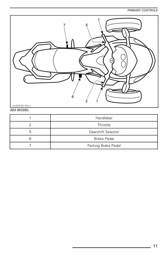
SE5 MODEL
1 Handlebar
2 Throttle
5 Gearshift Selector
6 Brake Pedal
7 Parking Brake Pedal
_______________ 11

PRIMARY CONTROLS
1) Handlebar
Grip the handlebar with both hands.Steer the handlebar in the directionyou want to go.
2) Throttle
The throttle is the right handgrip, and itcontrols engine speed. To increase en-gine speed, roll the throttle as shown(lower your wrist).
rmo2014-003-004_g
TO INCREASE SPEED
To decrease engine speed, roll thethrottle as shown (raise your wrist).
rmo2014-003-004_j
TO DECREASE SPEED
The throttle is spring loaded and shouldreturn to idle when you release yourgrip.
NOTE: This vehicle is equipped withan ETC (Electronic Throttle Control).The throttle plates in the throttle bodyare controlled electronically and can beopened or closed irrespective of thethrottle twist grip position when nec-essary. It may happen that when youaccelerate, the VSS (Vehicle StabilitySystem) prevents engine accelerationin order to maintain vehicle stability.Then, when the vehicle is stabilized,the engine RPM would increase as re-quested if the throttle was maintained.This would be felt as a "delayed" accel-eration.
3) Clutch Lever(SM5 Model)
The clutch lever is in front of the lefthandgrip. The clutch controls thetransmission of power from the en-gine to the rear wheel. The lever issqueezed in to disengage power andeased out to engage power.
Clutch Lever Position Adjustment
The distance between the clutch leverand handgrip can be adjusted from po-sition 1 (greatest distance) to position 4(smallest distance).
1. Push the clutch lever forward to re-lease the adjuster dial. Hold in posi-tion.
2. Turn the adjuster dial to the desiredposition aligning the dial numberwith the dot on the lever.
3. Release the clutch lever.
12 ______________

PRIMARY CONTROLS
rmo2010-001-033_a
CLUTCH LEVER ADJUSTMENT
1. Clutch lever2. Adjuster dial3. Dot
4) Gearshift Lever(SM5 Model)
The gearshift lever is in front of the leftfootrest.
The gear pattern is:Reverse-1- Neutral-2-3-4-5.
rmo2010-001-034_a
TYPICAL
Lift up or press down fully to move se-quentially from one gear to the next.When the lever is released, it returnsto center where the mechanism resetsfor the next shift up or down. Neutral(N) is selected by either a half lift fromfirst gear or a half press from secondgear.
NOTE: To shift from neutral to firstgear, press the brake and shift up.
To shift into reverse, refer to the OPER-ATING IN REVERSE in BASIC PROCE-DURES subsection for detailed instruc-tions.
5) Gearshift Selector(SE5 Model)
The gearshift selector is below the lefthandgrip.
rmo2013-001-013_a
TYPICAL1. Gearshift selector
Press selector forward to upshift. Pullselector toward you to downshift.
rmo2013-001-014_a
TYPICAL1. Upshift2. Downshift
_______________ 13

PRIMARY CONTROLS
This shifts sequentially from one gearto the next. Release the selector aftershifting.
To shift through multiple gears, use theselector multiple times.
To shift into neutral from first gear orreverse, briefly press or pull the gearselector. A longer activation will shiftover neutral.
When the gearshift selector is re-leased, the mechanism resets for thenext shift up or down.
If operator does not downshift whenslowing down and engine RPM dropsbelow a threshold value, the gearboxwill automatically downshift to thenext available gear.
If the engine is started with the gear-box in gear, it will automatically shift toneutral position.
6) Brake Pedal
The brake pedal is in front of the rightfootrest. Press it down to operate.This pedal brakes all three wheels.
rmo2008-001-008_a
1. Brake pedal2. Footrest
7) Parking Brake Pedal
The parking brake pedal is behind theoperator's left footrest.
rmo2008-001-079_a
1. Parking brake pedal
With the vehicle stopped, press itdown firmly until it locks to apply theparking brake. Firmly press the pedaldown a second time to release theparking brake.
rmo2008-001-080_a
1. Engaging/disengaging parking brake pedal
WARNINGDo not use the parking brake toslow or stop the vehicle; you couldlose control, spin, tip or roll over.Warn passenger not to touch itwith their left foot.
Operate the parking brake pedal onlywhile seated on the stopped vehicle.
14 ______________

SECONDARY CONTROLS
rmo2013-001-010_a
TYPICAL
1 Ignition switch 6 Headlights switch
2 Engine start button 7 Turn signal button
3 Engine stop switch 8 Horn button
4 Hazard warning switch 9 RECC (Roadster Electronic Command Center)
5 Cruise control switch 10 Reverse button
_______________ 15

SECONDARY CONTROLS
1) Ignition Switch
rmo2008-001-002_a
IGNITION SWITCH
1. OFF2. ON3. Front storage compartment opening4. Seat opening/fuel tank access5. Steering lock position
The ignition switch is located in thecenter of the handlebar. It controls:
– Engine ignition
– Seat opening mechanism to access:
• Fuel tank cap
• Brake fluid reservoirs.
– Front storage compartment open-ing mechanism to access:
• Fuses
• Battery terminals.
– Steering-lock mechanism.
NOTICE If the key does not turneasily, do not force it. Pull it out andreinsert.
WARNINGIf you turn the ignition switch toOFF, it shuts off the engine and allthe electrical systems includingthe VSS and DPS. If you do thiswhile the vehicle is moving, youcould lose control and crash.
NOTE: You should receive two keyswith your vehicle. Each key con-tains a computer chip specifically pre-programmed to allow starting the en-gine. Store the spare key in a safeplace because you must have yourspare key to have another one made byan authorized Can-Am roadster dealer.
Ignition Function
OFF
The key can be inserted or removed inthis position only.
In the OFF position, the electrical sys-tem of the vehicle is disabled.
The engine is shut down by turning theignition switch to the OFF position.
ON
When the key is turned to this position,the electrical system of the vehicle isactivated.
The gauge should wake-up.
The vehicle lights are turned on.
The engine can be started.
2) Engine Start Button
The engine start button is near the righthandgrip. When depressed and held, itstarts the engine.
3) Engine Stop Switch
The engine stop switch is near theright handgrip. It has two positions andmust be set to the run position beforeyou can start the engine. It allows youto stop the engine anytime without re-moving your hand from the handlebar.
4) Hazard Warning Switch
The hazard warning switch is nearthe right handgrip. Push the buttonto the left to turn on the hazard warn-ing lights.
5) Cruise Control Switch(RS-S Models Only)
The cruise control switch is near theright handgrip.
16 ______________

SECONDARY CONTROLS
rmo2014-003-004_d
1. Cruise control switch
The switch is a multifunction switch.It allows to activate, set and stop thefunction of the cruise control.
When set, the cruise control allows tomaintain a steady speed while ridingthe vehicle. It will increase or reduceengine speed as necessary.
NOTE: The vehicle torque may varyslightly depending on the road condi-tions such as the wind, going downhillor uphill.
The cruise control is designed to beused for prolonged drives on low traf-fic highways. Never ride the vehiclewith the cruise control activated incity streets, winding roads, in adverseweather or in any circumstances whenyou need the throttle control.
Cruise Control Limitations
The cruise control is not an automaticpilot, it will not drive the vehicle.
The cruise control is not aware of whatis going on the road and it does notsteer or apply the brakes for you.
WARNINGImproper use of the cruise controlcan lead the vehicle to a loss ofcontrol.
Setting the Cruise Control
To use the cruise control, the vehiclespeed must be above approximately40 km/h (25 MPH).
Turn the cruise control to ON by slidingthe cruise control button to the right.
rmo2014-003-004_e
1. Slide button to the right
NOTE: The cruise control status willshow CRUISE ON in the digital display.
Bring the vehicle at the speed you wantto maintain then press the cruise but-ton downward to SET the speed.
rmo2014-003-004_f
1. Push button downward to SET
NOTE: The cruise control status willshow CRUISE SET in the digital dis-play.
You can now release the throttle.
WARNINGAlways keep both hands on thehandlebar while riding. Other-wise, this could cause a vehicleloss of control.
NOTE: You can increase engine speedusing the throttle grip if you need to gofaster than the set speed. Releasingthe throttle will allow the cruise controlto recover the set speed.
Once the cruise control has been set,the speed setting may be increasedor reduced by pushing the button UPor DOWN. Each press of the button
_______________ 17

SECONDARY CONTROLS
will change the speed setting by incre-ments of 1.6 km/h (1 MPH). Holdingthe button will change the speed set-ting until released or the operating limithas been reached.
rmo2014-003-004_i
CRUISE CONTROL PREVIOUSLY SET1. Push up button to increase the speed
setting
rmo2014-003-004_f
CRUISE CONTROL PREVIOUSLY SET
1. Push down button to reduce the speedsetting
Stopping the Cruise Control
To completely stop the cruise controloperation, slide the cruise control but-ton to the left.
rmo2014-003-004_h
1. Slide button to OFF
NOTE: The CRUISE ON status will dis-appear in the digital display.
Cancelling the Cruise Control
Any of the following event will cancelthe cruise control and give you backthe throttle control. It then can be re-sumed if desired.
– Pressing the brake pedal.
– Squeezing the clutch lever or ifclutch slippage occurs (SE5 mod-els).
– Gear change (SE5 model).
– Any vehicle stability system inter-vention.
NOTE: When cancelling the cruisecontrol, you may activate the throt-tle lever up to the desired position tomake the transition smoother.
Resuming the Cruise Control
If the cruise control was cancelled andthe cruise control switch is still at theON position, the cruise control oper-ation can be resumed by pushing thecruise control button up. The cruisecontrol will then recover the previousset speed.
rmo2014-003-004_i
CRUISE CONTROL PREVIOUSLYCANCELLED
1. Push up button to RESUME
NOTE: The cruise control status willshow CRUISE SET in the digital dis-play.
18 ______________

SECONDARY CONTROLS
6) Headlights Switch
Headlights
The switch is near the left handgrip,and is used to select high or low beamfor the headlight. The headlights au-tomatically turn on when the enginereaches 800 RPM.
To select high beams, push the switchto the front position. To select lowbeams, push the switch to the backposition.
To flash the high beams, push theswitch down, then release it. The highbeams will stay on as long as you holddown the switch.
rmo2013-001-012_a
1. High beams2. Low beams3. Flash high beams
7) Turn Signal Button
Left side turn signal
Right side turn signal
The turn signal button is located nearthe left handgrip. It turns off automat-ically after a normal turn, but you mayhave to turn it off manually after a shal-low turn or lane change.
To turn the signal off, press the buttonin.
Turn signals will automatically turn offafter 30 seconds while the vehicle ismoving.
8) Horn Button
The horn button is located near the lefthandgrip.
9) RECC(Roadster ElectronicCommand Center)
The RECC is located near the left hand-grip.
rmo2013-001-013_b
1. RECC
The RECC is a multifunction switch.
The RECC allows the control of nu-merous functions of the multifunctiongauge.
NOTE: Inputs given to the RECC maybe halted for a short delay as the vehi-cle electronic modules prioritize vehi-cle main functions. This should not beconsidered a malfunction.
_______________ 19

SECONDARY CONTROLS
rmo2010-001-021_a
RECC BUTTONS1. MODE button: Navigate through the
screens2. SET button:
Quick press then release: Navigatesthrough the secondary screensHolding button more than 1 second: Setsa value in the current function or navigateto a setup screen
3. UP button: Increase the value4. DOWN button: Decrease the value5. LEFT button: Move the screen arrows to
the left to select a secondary menu or asetting
6. RIGHT button: Move the screen arrowsto the right to select a secondary menu ora setting
WARNINGUsing the RECC while driving candistract the driver from operatingthe vehicle. Always use buttonswith caution and always keep youreyes on the road.
10) Reverse Button
Reverse button R
The reverse button is located near theleft handgrip.
rmo2013-001-013_c
1. Reverse button
Push and hold the reverse button to al-low shifting into reverse. Refer OPER-ATING IN REVERSE in BASIC PROCE-DURES subsection for detailed instruc-tions.
The hazard warning lights flash whenthe vehicle is in reverse.
20 ______________

MULTIFUNCTION GAUGE CLUSTER (BASE MODEL)
The multifunction gauge cluster includes gauges (speedometer, tachometer, en-gine temperature, fuel level), indicator lamps and a user selectable digital display.
Description
1 9 2
3
45678
3
rmo2013-001-015_a
1) Analog Speedometer
Measures vehicle speed in kilometersor miles per hour. To change units, re-fer to SETTING METRIC/IMPERIALUNIT.
2) Analog Tachometer (RPM)
Measures engine revolutions perminute (RPM). Multiply by 1000 to ob-tain actual revolutions.
3) Indicator Lamps
Indicator lamps will inform you of vari-ous conditions or problems (see MES-SAGES IN MULTIFUNCTION GAUGEin ROAD SIDE REPAIRS section.
_______________ 21

MULTIFUNCTION GAUGE CLUSTER (BASE MODEL)
INDICATOR LAMPS (NORMAL OPERATION)
INDICATOR LAMP(S)MAIN DIGITAL
DISPLAYDESCRIPTION
All indicatorlamps
On None
All indicator lamps are activatedwhen ignition switch is setto ON and the engine is notstarted.
Flashing PARK BRAKE Parking brake engaged.
! Flashing +Beeper
None
SE5 model: The ignition switchis OFF and the parking brake isnot engaged. Always engagethe parking brake when parkingthe vehicle.
N On None Gearbox in neutral position.
R Flashing None Gearbox in reverse position.
On NoneHeadlights in the HIGH beamposition.
Flashing None VSS intervention occurs.
Flashing NoneTurn signal or hazard warninglights flashing.
4) Main Digital Display
Displays useful real-time informationto the rider.
For display function informations, referto DIGITAL DISPLAY INFORMATION.
5) Fuel Level
Bar gauge that continuously indicatesthe amount of fuel left in the fuel tank.
6) Secondary Digital Display
Displays useful real time informationto the rider. For display function infor-mations, refer to DIGITAL DISPLAYINFORMATION.
7) Gearbox Position
Displays the selected gearbox posi-tion.
8) Engine Temperature
Bar gauge that continuously indicatesthe engine coolant temperature.
9) Digital Speedometer
In addition of the analog typespeedometer, vehicle speed canalso be indicated via this display.
Speed can be displayed in kilometers(Km/h) or miles per hour (MPH). Tochange units, refer to SETTING MET-RIC/IMPERIAL UNITS.
22 ______________

MULTIFUNCTION GAUGE CLUSTER (BASE MODEL)
Startup and Shutdown
Any time the ignition switch is set toON after having been in the OFF posi-tion for five minutes or more, the maindigital display will scroll the followingmessage:
– BEFORE OPERATING READ THESAFETY CARD ABOVE THENPRESS MODE BUTTON.
NOTE: Acknowledge this message toallow engine starting.
Digital Display Information
WARNINGDo not adjust the display while riding. You could lose control.
Main Display Functions
Pressing the SET button on the RECC will scroll through the different functions.
FUNCTION SEQUENCE INFORMATION DISPLAYED
Outside temperatureXX °C (Celsius)
XX °F (Fahrenheit)
Tachometer (revolutions per minutes) XXXX RPM
Secondary Display Functions
Pressing the MODE button on the RECC will scroll through the different functions.
FUNCTION SEQUENCE INFORMATION DISPLAYED
ClockXX:XX (24:00 time base)
XX:XX A or P (12:00 AM/PM time base)
Cumulative distance odometer XXXXX.X Km or mi
Trip distance — odometer A (TRIP A) XXXXX.X Km or mi
Trip distance — odometer B (TRIP B) XXXXX.X Km or mi
Trip time chronometer (HrTRIP) XXXXX.X
Engine time chronometer (Hr) XXXXX.X
Date (Month - Day) XX-XX Month and Day
To reset any trip functions, push and hold the MODE button for three seconds.
Display Settings
Setting Metric/Imperial Units
1. Push and hold SET button on theRECC for three seconds.
2. Push _down arrow_ to select KM,push up arrow to select MI.
_______________ 23

MULTIFUNCTION GAUGE CLUSTER (BASE MODEL)
Setting Clock
1. Press MODE button to select clockdisplay.
2. Push and hold MODE button forthree seconds.
3. Press down arrow to select 12:00AM PM or up arrow to select 24:00time base.
4. If 12:00 AM PM time base is se-lected, AM PM is displayed in upperLCD.Press up or down arrow to se-lect A (AM) or P (PM).
5. Press on the right arrow to displayHr in upper LCD. The hour numberflashes in the lower LCD. Press upor down arrow to select the applica-ble hour value.
6. Press on the right arrow to displayMin in upper LCD. The minute num-ber flashes in the lower LCD. Pressup or down arrow to select the ap-plicable minute value.
7. When completed, press the right ar-row to exit the menu.
NOTE: You can always return to previ-ous selection using the left arrow.
Setting Language
The gauge display language can bechanged. Refer to an authorizedCan-Am roadster dealer for languageavailability and setup the gauge to yourpreference.
24 ______________

MULTIFUNCTION GAUGE (RS-S MODEL)
WARNINGWatching or using the multifunction gauge or the infotainment centercan distract the driver from the operation of the vehicle. Always keep onobserving the traffic and make sure the surrounding is clear and safe beforedoing so.
The multifunction gauge includes analog gauges (speedometer and tachometer),indicator lamps and an infotainment center with a digital screen.
Description
rmo2014-001-004_a
1) Analog Speedometer
Displays vehicle speed in kilometers(km/h) or miles per hour (MPH). Tochange units, refer to PREFERENCESSCREEN.
2) Analog Tachometer (RPM)
Displays engine revolutions per minute(RPM). Multiply by 1000 to obtain ac-tual revolutions.
3) Indicator Lamps
Indicator lamps will inform you of var-ious conditions or problems (see alsoMESSAGES IN MULTIFUNCTIONGAUGE in ROAD SIDE REPAIRS sec-tion.
_______________ 25

MULTIFUNCTION GAUGE (RS-S MODEL)
INDICATOR LAMPS (NORMAL OPERATION)
INDICATOR LAMP(S) MAIN SCREEN DESCRIPTION
All indicatorlamps
On NoneTemporarily all indicator lamps areactivated when ignition switch is ON andthe engine is not started
Flashing None Parking brake engaged
! Flashing +Beeper
None
SE5 model: The ignition switch is OFF andthe parking brake is not engaged. Alwaysengage the parking brake when parkingthe vehicle
N On None Gearbox in neutral position
R Flashing None Gearbox in reverse position
On None Headlights in the HIGH beam position
Flashing None VSS intervention occurs
Flashing None
Left side turn signal.Left and right side indicator lightsflash at the same time: hazard warninglights
Flashing None
Right side turn signal.Left and right side indicator lightsflash at the same time: hazard warninglights
4) Digital Display
Displays useful real-time informationto the rider and is used as an interfacefor the infotainment center.
The display will use a light color whenthe ambient light is bright and will au-tomatically change to a darker colorwhen the ambient light is dusky.
For a complete description of the dig-ital display, refer to DIGITAL DISPLAYDESCRIPTION.
26 ______________

MULTIFUNCTION GAUGE (RS-S MODEL)
Multifunction GaugeStartup Information
A self test is initiated every time theignition key is turned ON. The defaultriding screen will turn on and indicatorlights will turn on for a moment. Thisallows the operator to validate that allindicators are working properly.
Any time the ignition switch is turnedON after having been in the OFF posi-tion for 5 minutes or more, the digitaldisplay will show the following mes-sage:
– BEFORE OPERATING READ THESAFETY CARD ABOVE THENPRESS MODE BUTTON.
Press the MODE button to acknowl-edge this message to allow enginestarting.
Digital DisplayDescription
The display is divided in several areasas follows.
8
2 3
74 65
1
rmo2010-001-015_den
1. Category icons2. Ambient temperature3. Clock4. Gearbox position5. Cruise control status6. Trip meter7. Odometer8. Main screen
1) Category Icons
There are 3 selectable category icons.Each icon is linked to a differentscreen. See table below.
CATEGORYICON
CATEGORY ICONSCREEN
Default riding
Trip meter
Preferences (onlyavailable when vehicle
is stopped)
For a complete description, refer toCATEGORY ICON SCREEN DESCRIP-TION.
You can navigate through the categoryicons to select several functions andto change certain settings using theRECC (Roadster Electronic CommandCenter). Refer to RECC (ROADSTERELECTRONIC COMMAND CENTER)in SECONDARY CONTROLS subsec-tion.
2) Ambient Temperature
The ambient air temperature is dis-played in °C or °F. To change units,refer to PREFERENCES SCREEN.
3) Clock
The current time is displayed in 24h oram/pm format. To change the format,refer to PREFERENCES SCREEN.
4) Gearbox Position
Displays the selected gearbox posi-tion.
5) Cruise Control Status
Displays ON when the cruise control isturned on but not set to any speed.
Displays SET when the cruise control isin operation and a speed has been set.
_______________ 27

MULTIFUNCTION GAUGE (RS-S MODEL)
Displays OFF when the cruise controlis not in use.
6) Trip Meter
Distance travelled in kilometers ormiles since the last reset. Two tripmeters are available and they are iden-tified as "A" and "B". To change units,refer to PREFERENCES SCREEN.
As a second function, the trip metermay display an icon to inform the driverof a malfunction. Refer to MESSAGESIN MULTIFUNCTION GAUGE in theROAD SIDE REPAIRS section.
rmr2011-079-006_a
1. Icon
7) Odometer
Total distance travelled in kilometers ormiles since the delivery from the fac-tory. To change units, refer to PREF-ERENCES SCREEN.
8) Main Screen
The main screen is the area where themost information is displayed. Thedisplay will change when navigatingthrough the available gauge functions.
rmo2010-001-015_en
TYPICAL – DEFAULT RIDING SCREEN
SHOWN
For a complete description of thescreens, refer to CATEGORY ICONSCREEN DESCRIPTION.
Navigating in the DigitalDisplay
We recommend you practice selectingsome functions on the infotainmentcenter before getting on the road. Youwill get used to them and they will beeasier to use on the road.
Use the RECC (Roadster ElectronicCommand Center) to control the dis-play functions. Refer to RECC (ROAD-STER ELECTRONIC COMMAND CEN-TER) in SECONDARY CONTROLS sub-section.
rmo2013-001-013_b
1. RECC
28 ______________

MULTIFUNCTION GAUGE (RS-S MODEL)
Pressing the MODE button will movea selection through the category icons,located at the top left area of thescreen, in this order: Default ridingscreen, Trip meter and Preferences.Each press of the button will move theselection to the next available icon.When an icon is selected, its relatedscreen will appear.
NOTE: The Preferences Screen isskipped when vehicle is above 5 km/h(3 MPH).
1
2
rmo2010-001-015_ben
1. Category icons2. Default riding icon selected
When the selection is on the last icon,it will then move to the first icon whenthe MODE button will be pressed.
In some screens, vertical or horizontalarrows are visible. This indicates thatyou have to use the LEFT/RIGHT but-ton to change the setting enclosed bythe horizontal arrows and to use theUP/DOWN button to change the set-ting enclosed by the vertical arrows.
When a double arrow is visible, it indi-cates the following depending on thedisplayed screen:
– Holding the related arrow button willscroll the values to the end or to thebeginning.
– Using the related arrow button willscroll the list to reveal the remainingitems.
When an item is selected, this sets theitem to the current value.
After acknowledging the initial safetymessage at gauge startup, or aftera few seconds elapsed in any otherscreen without pressing any RECCbutton, the display will automaticallyreturn to the default riding screen.
Category Icon ScreenDescription
Default Riding Screen
21
4
3
rmo2013-001-012_aen
DEFAULT RIDING SCREEN1. Engine coolant temperature (option
package)2. Fuel level (option package)3. Digital speedometer4. Engine speed (not factory set)
1) Engine Coolant Temperature
Bar gauge that continuously indicatesthe engine coolant temperature.
2) Fuel Level
Bar gauge that continuously indicatesthe amount of fuel left in the fuel tank.
3) Digital Speedometer
Displays vehicle speed in kilometers(km/h) or miles per hour (MPH). Tochange units, refer to PREFERENCESSCREEN.
4) Engine Speed
Displays engine speed in revolutionsper minute (RPM).
_______________ 29

MULTIFUNCTION GAUGE (RS-S MODEL)
NOTE: This is not a default setting. Toactivate this function, refer to PREFER-ENCES SCREEN.
Trip Meter Screen
1 2 3
rmo2010-001-024_aen
TYPICAL
1. Display selection: Trip A or Trip B2. Pause or resume the selected trip meter3. Reset the selected trip meter
Press the LEFT/RIGHT button to selectthe desired trip meter.
Press the UP button to pause or re-sume the selected trip meter.
Press the DOWN button to reset theselected trip meter.
Preferences Screen
rmr2010-030-058_aen
1. 1st column: Main category2. 2nd column: Secondary category or item3. 3rd column: Unit or setting
This screen is only available when vehi-cle is stopped.
Use the LEFT/RIGHT button to selectthe desired column.
Within a column, use the UP/DOWNbutton to select the desired item. Ifmore items are available to the nextright column, use the RIGHT buttonto select the column then use againthe UP/DOWN button to select the de-sired item. Continue using this patternto reach the desired item.
When an item is selected, this setsthe item to the current value. You maythen go to any screen, the value will bekept.
rmr2010-030-057_aen
1. The selected value will be set
NOTE: When in the 2nd or 3rd column,you can go back to the column at theleft using the LEFT button.
NOTE: When the units are changedthey will be changed on both the ana-log and the digital displays. The unitswill be used for the odometer and bothtrip meters.
Setting the Time
To set the hours:
Select CLOCK in main category of Pref-erences Screen.
30 ______________

MULTIFUNCTION GAUGE (RS-S MODEL)
rmo2011-001-202_a
Select HOURS in secondary category.
Adjust the unit value using the UP andDOWN arrow.
To set the minutes:
Select CLOCK in main category of Pref-erences Screen.
rmo2011-001-201_a
Select MINUTES in secondary cate-gory.
Adjust the unit value using the UP andDOWN arrow.
Selecting the Hour Mode
To select the 12/24 hour mode:
Select CLOCK in main category of Pref-erences Screen.
rmo2011-001-203_a
Select 12/24 HOUR in secondary cate-gory.
Select the appropriate value in mainunit or setting.
_______________ 31

EQUIPMENT
Mirrors
Adjusting Mirrors
Press the mirror at the points shownbelow to adjust its position in the fourdirections.
rmo2008-001-081_a
MIRROR ADJUSTMENT POINTS
Locking the Handlebar
To lock the steering mechanism:
1. Insert key in ignition switch.
2. Rotate the handlebar all the way tothe right or to the left.
3. Turn the key 1/4 turn counterclock-wise to the steering lock positionthen remove key.
rmo2008-001-074_a
KEY POSITION TO LOCK HANDLEBAR1. Turn key 1/4 turn
Front StorageCompartment
Opening the Front StorageCompartment
1. Insert key in ignition switch.
2. Push and turn the key 1/4 turn coun-terclockwise to the front storagecompartment position and holdwhile lifting cover.
NOTE: It is possible to open the frontstorage compartment with the enginerunning.
rmo2008-001-070_a
KEY POSITION TO OPEN FRONT STORAGECOMPARTMENT1. Push key2. Turn key 1/4 turn
rmo2008-001-010
FRONT STORAGE COMPARTMENT OPENED
Tool Kit
Tool Kit Location
The tool kit is located inside the frontstorage compartment.
32 ______________

EQUIPMENT
rmo2013-003-007_e
TYPICAL1. Tool kit
Operator's Guide
The operator's guide is located withthe SAFETY DVD video inside the frontstorage compartment.
rmo2013-003-007_f
TYPICAL1. Operator's guide
Seat
Opening the Seat
1. Insert key in ignition switch.
2. Push and turn the key 1/4 turn clock-wise to the seat opening positionand hold while lifting seat.
rmo2008-001-071_a
KEY POSITION TO OPEN SEAT
1. Push key2. Turn key 1/4 turn
NOTICE Do not force the seat pastthe maximum opening angle or itmay break.
rmo2008-001-011_a
1. Maximum opening of seat
Body Panels
The body panels on the vehicle can beremoved for maintenance.
rmo2013-001-007_a
TYPICAL - LEFT HAND SIDE PANELS1. Middle side panel2. Inner side panel3. Bottom side panel
_______________ 33
EQUIPMENT
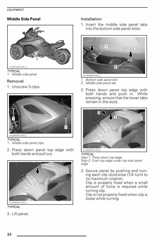
Middle Side Panel
rmo2013-001-001_b
TYPICAL1. Middle side panel
Removal
1. Unscrew 3 clips.
rmo2008-001-032_a
TYPICAL
1. Middle side panel clips
2. Press down panel top edge withboth hands and pull out.
rmo2008-001-033_a
TYPICAL
3. Lift panel.
Installation
1. Insert the middle side panel tabsinto the bottom side panel slots.
rmo2008-001-034_a
1. Bottom side panel slot2. Middle side panel tab
2. Press down panel top edge withboth hands and push in. Whilepressing, ensure that the lower tabsremain in the slots.
rmo2008-001-033_b
TYPICALStep 1: Press down top edgeStep 2: Push top edge under top side paneledge
3. Secure panel by pushing and turn-ing each clip clockwise (1/4 turn) toits maximum rotation.Clip is properly fixed when a smallamount of force is required whileturning clip.Clip is not properly fixed when clip isloose while turning.
34 ______________

EQUIPMENT
rmo2008-001-035_a
Inner Side Panel
Inner Side Panel Removal
rmo2013-001-008_a
TYPICAL1. Inner side panel
1. Remove middle side panel.
2. Unscrew Torx screw.
rmo2013-001-008_b
1. Torx screw2. Plastic rivet3. Clip
3. Remove plastic rivet.
4. Slide the inner side panel to releasethe clip.
Inner Side Panel Installation
1. Slide the inner side panel back in po-sition.
2. Install plastic rivets and screw inTorx screw.
NOTICE Do not overtorque. Anydeformation on the panel aroundthe screw is an indication that itis too tight. You may damage thepanel.
Bottom Rear Side Panel
Bottom Rear Side Panel Removal
rmo2013-001-009_a
TYPICAL1. Bottom rear side panel
1. Unscrew the two screws from thebottom rear side panel.
2. Carefully slide the panel forward todisengage the tabs from the brack-ets.
_______________ 35

EQUIPMENT
rmo2013-003-026_a
TYPICAL - INNER SIDE OF PANEL1. Tabs2. Brackets
3. Once the panel is disengaged, tiltthe bottom part towards you andlower the panel to release the top.
4. Remove the bottom rear side panel.
rmo2013-001-009_b
TYPICAL1. Bottom rear side panel Torx screws
Bottom Rear Side Panel Installation
1. Place the top part of the panel intoposition.
2. Tilt the bottom of the panel and in-sert it until it the tabs are in front ofthe brackets.
NOTE: Make sure the clip is properlyinserted in the footrest support.
rmo2014-001-005_a
1. Clip
3. Carefully slide the panel back untilthe tabs are in front of the brackets.
4. Screw the 2 Torx screws.
NOTICE Do not overtorque. Anydeformation on the panel aroundthe screw is an indication that itis too tight. You may damage thepanel.
Storage Compartment Latch
Storage Compartment LatchLubrication
Use CABLE LUBRICANT (P/N 293 600041) or the equivalent.
36 ______________

BASIC PROCEDURES
Starting and Stopping theEngine
Starting the Engine
WARNINGExhaust gas contains poisonouscarbon monoxide that can rapidlyaccumulate in an enclosed orpoorly ventilated area. If inhaled,it can cause serious injury ordeath.Only run the engine in an unen-closed, well ventilated area. SeeAVOID CARBON MONOXIDE POI-SONING.
SSSSMMMM5555 MMMMooooddddeeeellll
1. Push down and hold the brakepedal.
2. Turn the key to ON.
NOTICE Do not apply throttlewhile electrical system is initializ-ing.
3. Refer to the Safety Card as neededto prepare yourself, your passen-ger and the vehicle, then press theMODE button to enable the starter.
4. Set the engine stop switch to theRUN/ON position.
5. Pull in and hold the clutch lever.
6. Shift into NEUTRAL. Check the mul-tifunction gauge cluster to be sureyou are in neutral.
7. Press and hold the engine start but-ton until the engine starts. Do nothold the start button for more than15 seconds. If it does not start, re-lease the button and wait 30 sec-onds to let the starter cool downbefore trying again.
NOTICE Do not apply throttlewhile starting the engine.
8. Check the display for problems andto ensure that the oil light turns off.
9. Release the parking brake. Makesure the parking brake indicator onthe multifunction gauge cluster isoff.
NOTICE If the parking brake is notfully released before operating thevehicle, brake pads will drag whileyou are moving. This can damagethe brake system.
SSSSEEEE5555 MMMMooooddddeeeellll
NOTE: The SE5 model can be startedin any gear with the brake pedal de-pressed. The transmission automati-cally shifts to neutral when the enginestarted.
1. Push down and hold the brakepedal.
2. Turn the key to ON.
NOTICE Do not apply throttlewhile electrical system is initializ-ing.
3. Refer to the Safety Card as neededto prepare yourself, your passen-ger and the vehicle, then press theMODE button to enable the starter.
4. Set the engine stop switch to theRUN/ON position.
5. Press and hold the engine start but-ton until the engine starts. Do nothold the start button for more than15 seconds. If it does not start, re-lease the button and wait 30 sec-onds to let the starter cool downbefore trying again.
NOTICE Do not apply throttlewhile starting the engine.
6. Check the display for problems andto ensure that the oil light turns off.
7. Release the parking brake. Makesure the parking brake indicator onthe multifunction gauge cluster isoff.
_______________ 37

BASIC PROCEDURES
NOTICE If the parking brake is notfully released before operating thevehicle, brake pads will drag whileyou are moving. This can damagethe brake system.
Stopping the Engine
SSSSMMMM5555 MMMMooooddddeeeellll
1. Shift into first gear.
2. Set the engine stop switch to OFF.
3. Engage the parking brake. Thebrake locks in the depressed posi-tion, and a scrolling message PARKBRAKE will appear on the display.
4. Turn the key to OFF.
5. Before dismounting, check that theparking brake is fully engaged. Holdthe clutch and rock the vehicle backand forth.
NOTE: As the brake pads wear, youmay need to push the parking brakelever farther to engage the brake.
WARNINGAlways fully engage the parkingbrake. The vehicle can roll if theparking brake is not fully engagedand the transmission is in neutral.
SSSSEEEE5555 MMMMooooddddeeeellll
1. Shift into neutral.
2. Set the engine stop switch to OFF.
3. Engage the parking brake. Thebrake locks in the depressed posi-tion, and a scrolling message PARKBRAKE will appear on the display.
4. Turn the key to OFF.
NOTE: If the parking brake is not en-gaged while the key is OFF, the parkbrake indicator light will flash and abeeper will sound.
5. Before dismounting, check that theparking brake is fully engaged. Rockthe vehicle back and forth.
NOTE: As the brake pads wear, youmay need to push the parking brakelever farther to engage the brake.
WARNINGAlways fully engage the parkingbrake. The vehicle can roll if theparking brake is not fully engaged,regardless of what gear it is in.The centrifugal clutch is alwaysdisengaged when the vehicle isstopped, so the transmission willnot hold the vehicle in place.
AAAAllllllll MMMMooooddddeeeellllssss
This vehicle is equipped with an Elec-tronic Throttle Control (ETC).
Each time the ignition switch is turnedOFF, the ETC motor stays energized for40 minutes.
The ETC motor will emit a high fre-quency sound during this period oftime that can be heard in a quiet envi-ronment.
This is a normal characteristic of the ve-hicle.
Pushing the Vehicle
CAUTION Avoid pushing thevehicle on a slope. If you must pushthe vehicle on a slope, take extracare to stay within reach of the brakepedal in case the vehicle starts toroll.
To move the vehicle a short distancewithout starting the engine:
1. While seated on the vehicle, pushdown and hold the brake pedal.
2. Shift the transmission into NEU-TRAL (SM5 model).
3. Disengage the parking brake.
4. Dismount on the right side of the ve-hicle, keeping your foot on the brakepedal.
5. Push the vehicle, using the brake asneeded.
38 ______________

BASIC PROCEDURES
CAUTION Only push from theright side, so you can reach the brakepedal. Stay clear of the hot exhaustpipe.When pulling the vehicle backward,be careful that the front wheel doesnot roll over your feet.
6. Remount the vehicle and park asspecified above.
Operating in Reverse
For safe operation in reverse, refer toSAFE OPERATING INSTRUCTIONSsection.
Shifting Into Reverse (SM5 Model)
1. With engine running, shift into firstgear.
2. Hold in the clutch lever.
3. Press and hold the reverse button.
4. Step down on the shift lever onestroke.
5. Release the reverse button andcheck that the letter "R" flashes onthe multifunction gauge cluster andthe hazard warning lights flash.
Shifting Into Reverse (SE5 Model)
1. With engine running. the roadsterstopped, and the brake depressed,shift into first gear or neutral.
2. Press and hold the reverse button.
3. Pull the gearshift selector towardyou to downshift to reverse.
Driving in Reverse
Check that the area behind you is clearand continue to look backwards whileyou operate in reverse. Keep yourspeed low and do not back up for longdistances.
Shifting Out of Reverse
SSSSMMMM5555 MMMMooooddddeeeellll
To shift out of reverse, hold in theclutch and lift the shift lever once toshift into first. You do not need to usethe reverse button — it resets auto-matically.
SSSSEEEE5555 MMMMooooddddeeeellll
To shift out of reverse, stop vehicle andpush on upshift selector quickly to shiftinto neutral and longer to shift in firstgear.
Operating During Break-In
A break-in period of 1 000 km (600 mi)is required for the vehicle.
During the first 300 km (200 mi), avoidhard braking.
WARNINGNew brakes and tires do not op-erate at their maximum efficiencyuntil their break-in is completed.Braking, steering and VSS perfor-mance may be reduced, so useextra caution.Brakes and tires take about 300 km(200 mi) of riding with frequentbraking and steering to break-in.For riding with infrequent brakingand steering, allow extra time tobreak-in the brakes and tires.
During the first 1 000 km (600 mi):
– Avoid full throttle acceleration.
– Avoid prolonged riding.
– If the cooling fan operates continu-ously during stop and go traffic, pullover and shut off the engine to let itcool off or speed up to let air cool offthe engine.
After the break-in period, your vehi-cle should be inspected by an autho-rized Can-Am roadster dealer as perthe MAINTENANCE SCHEDULE.
_______________ 39

BASIC PROCEDURES
Fueling
Fuel Requirements
NOTICE Always use fresh gaso-line. Gasoline will oxidize; the re-sult is loss of octane, volatile com-pounds, and the production of gumand varnish deposits which candamage the fuel system.
Alcohol fuel blending varies by coun-try and region. Your vehicle has beendesigned to operate using the recom-mended fuels, however, be aware ofthe following:
– Use of fuel containing alcohol abovethe percentage specified by gov-ernment regulations is not recom-mended and can result in the fol-lowing problems in the fuel systemcomponents:
• Starting and operating difficul-ties.
• Deterioration of rubber or plasticparts.
• Corrosion of metal parts.
• Damage to internal engine parts.
– Inspect frequently for the presenceof fuel leaks or other fuel systemabnormalities if you suspect thepresence of alcohol in gasoline ex-ceeds the current government reg-ulations.
– Alcohol blended fuels attract andhold moisture which may lead tofuel phase separation and can resultin engine performance problems orengine damage.
Recommended Fuel
Use premium unleaded gasoline withan AKI (RON+MON)/2 octane rating of91, or an RON octane rating of 95.
NOTICE Never experiment withother fuels. Engine or fuel systemdamages may occur with the use ofan inadequate fuel.
NOTICE Do NOT use fuel from fuelpumps labeled E85.
Use of fuel labeled E15 is prohibited byU.S. EPA Regulations.
Refueling Procedure
WARNINGGasoline is extremely flammableand highly explosive. Follow therefueling procedure to reducethe risk of fire or explosion. SeeAVOID GASOLINE FIRES ANDOTHER HAZARDS.
To refuel the vehicle:
1. Park outdoors in a well ventilatedarea away from flames, sparks, any-one smoking and other sources ofignition.
2. Stop the engine.
3. Unlatch and lift seat (see EQUIP-MENT subsection). The fuel cap islocated on the left side.
4. Slowly rotate cap counterclockwiseand remove it.
rmo2008-001-016
FUEL CAP ON LEFT SIDE UNDERNEATHSEAT
5. Fill the tank until the fuel levelreaches the higher point of the fillertube.
40 ______________

BASIC PROCEDURES
rmo2014-001-002_a
1. Higher point of the filler tube
NOTE: Do not try to top off the fueltank. Leave some room for the fuel toexpand with temperature changes.
6. Wipe up any spilled fuel. If fuel spillson you, wash with soap and waterand change your clothes.
7. Put cap on and fully tighten clock-wise until you hear a click. Neverstart or operate the engine with thefuel cap removed.
8. Close seat.
Adjusting Suspension(RS-S Models Only)
Front Suspension
WARNINGAdjust both springs to the sameload. Uneven adjustment cancause poor handling, loss of sta-bility and loss of control.
Verification conditions:
– Vehicle on a level surface
– Normal cargo load
– Rider and passenger taking place onthe vehicle.
Measure the distance between the up-per and lower shock absorber mount-ing bolts.
RECOMMENDED PRELOAD
420 mm (16-1/2 in)(rider+passenger+cargo)
To adjust:
1. Loosen the lock ring.
2. Bring the spring preload adjustmentring to the recommended setting.
rmo2012-001-001_b
1. Lock ring2. Spring preload adjustment ring
3. Lock the assembly by tightening thelock ring against the preload ring.
TORQUE
Lock ring 10 N•m (89 lbf•in)
_______________ 41

BASIC PROCEDURES
This page is
intentionally blank
42 ______________

SAFE OPERATING
INSTRUCTIONS
______ SAFE OPERATING INSTRUCTIONS ______ 43

WHAT'S DIFFERENT ABOUT THE SPYDERROADSTER
The Spyder roadster is a different typeof road vehicle. This section will helpyou understand some of the vehicledistinctive features and operating char-acteristics.
Stability
The three-wheeled “Y” configurationprovides greater low-speed stabilitythan a motorcycle. However, it is notas stable as a four-wheeled vehiclesuch as an automobile. Driving aidtechnologies, like the electronic Vehi-cle Stability System (VSS), help main-tain stability during maneuvers, butyou can still lose control, tip or roll thevehicle due to extreme maneuvers(such as hard turns at high speeds) orstriking uneven surfaces or objects.In addition, the operator or passengercan fall off due to hard turns, accelera-tion, braking or impacts.
Response to RoadConditions
The Spyder roadster responds differ-ently than other vehicles to certainroad conditions.
– Do not ride off-road or on ice orsnow.
– Avoid puddles and running water.The vehicle hydroplanes more eas-ily than a car. If you must go throughwater, slow down.
– Slow down on gravel, dirt or sandcovered roads.
Refer to STREET STRATEGIES sub-section for detailed instructions.
Brake Pedal
One pedal brakes all three wheels.There is no hand-operated brake, andthere is no way to brake front and rearwheels separately. The Spyder road-ster is better able to brake and steer atthe same time than a motorcycle. The
vehicle can stop quickly — be awareof vehicles behind you that may not beable to stop as quickly.
Anti-lock Braking System (ABS)
The vehicle is equipped with anAnti-lock Braking System (ABS) as partof the Vehicle Stability System (VSS).For hard braking, press and hold thebrake pedal. ABS will prevent wheelsfrom locking.
Parking Brake
!
The parking brake mechanically brakesthe rear wheel only, and it locks in placewhen engaged. It is not controlled bydriving aid technologies (e.g., ABS,Electronic Brake Distribution). Do notuse it to slow or stop the vehicle — youcould lose control, spin, tip or roll over.Warn passengers not to touch it withtheir left foot.
Steering
Direct Steering
To steer your Spyder roadster, alwayssteer in the direction of the turn.
Motorcyclists — Do not countersteeras it is done on a motorcycle. Unlikea motorcycle, your Spyder roadstercannot lean while turning. If you are amotorcyclist, you must relearn how toturn. Practice steering in the directionof the turn at all speeds until you areproficient.
Sideways Forces in Turns
Unlike a motorcycle, the Spyder road-ster does not lean in turns. You willfeel sideways forces pushing you tothe outside of the turn. To maintainbalance, the operator and passengermust hold on with both hands and
44 _____ SAFE OPERATING INSTRUCTIONS______

WHAT'S DIFFERENT ABOUT THE SPYDER ROADSTER
keep both feet firmly planted on thefootrests. In hard turns, it may help tolean your upper body forward and to-ward the inside of the turn.
Width
Because the Spyder roadster is widerthan a typical motorcycle:
– Keep the front wheels in your laneduring turns. Be particularly awareof where your front wheels are incurves and when passing. If youtake a path that would put a motor-cycle front wheel near the edge ofthe lane, the Spyder roadster frontwheel may be out of the lane.
– Do not share lanes or split lanes(ride between two lanes of traffic).Group riding should proceed in a sin-gle file, even with motorcycles.
– Be prepared to swerve farther toavoid obstacles.
Reverse
R
The Spyder roadster operates in re-verse like a car. However, there aresome important differences:
– The hazard warning lights flashwhen it is in reverse, but there areno backup lights. Be aware thatother motorists might not know thatyou are about to back up.
– If necessary, have the passengerdismount if your visibility is limited.
– Remember that the front is widerthan the rear. Do not back up tooclose to objects or you may hit themwith the front tires.
– Keep your speed low and do notback up for long distances.
– When possible, park so that you donot have to back out of the parkingspace.
– SM5 model: Shift back into firstgear before shutting off the engine.
CAUTION Always keep bothfeet on the pegs while operating inreverse. Never put your feet on theground while backing-up.
Driver's License and LocalLaws
Driver's license requirements for op-erating the Spyder roadster vary bylocation. Depending on local laws, youmay need a motorcycle endorsement,three-wheeled vehicle endorsement,or just a standard automobile driver'slicense.
Check with local authorities to makesure you have the proper license be-fore operating the vehicle on publicroads.
______ SAFE OPERATING INSTRUCTIONS ______ 45

DRIVING AID TECHNOLOGIES
Vehicle Stability System(VSS)
The Spyder roadster is equipped witha Vehicle Stability System (VSS). VSScan help you control the direction ofthe vehicle and reduce the risk of tip-ping or rolling over in some situations.VSS consists of:
– An Antilock Braking System (ABS)that helps maintain steering controlduring hard braking by preventingthe wheels from locking.
– An Electronic Brake Distribution(EBD) system that automatically ad-justs the brake balance between allthree wheels. With the ABS, EBDhelps maintain directional controland maximize the braking force de-pending on the traction available.
– A Traction Control System (TCS)that helps prevent the rear wheelfrom slipping. The TCS will limitrear wheel spin only if you turn thehandlebar (steer out of straight line)or if vehicle speed exceeds 50 km/h(31 MPH).
– A Stability Control System (SCS)is designed to limit the power driv-ing the rear tire and to brake individ-ual wheels, which reduces the riskof losing control of the vehicle orrolling over.
Limitations
VSS cannot help you maintain controlin all situations.
Surfaces with Poor Traction
The grip of tires on the road surfacelimits the maximum braking. Evenwith ABS and EBD, your stopping dis-tance will be longer on surfaces withpoor traction or if you do not maintaintire pressure and tread condition.
If your tires lose traction with the roadsurface you may lose control of the ve-hicle, even with VSS.
If the paved road surface is coveredor partially covered with ice, snowor slush, there is not enough tractionavailable to maintain control of the ve-hicle, even with VSS. Do not operateon snow, ice or slush.
Like other on-road vehicles, this ve-hicle can hydroplane on water (losetraction on a layer of water). If you ridetoo fast into a layer of water, such asa large puddle or flowing water on theroad, the vehicle can lose traction andspin out, and the VSS cannot keep youin control. Avoid large water puddlesor water streams, and slow down orpull off the road during heavy rains. Ifyou must pass through water, slowdown as much as possible before youreach it.
Reduce speed on surfaces with poortraction, like mud, sand, gravel or wetpavement. The Spyder roadster is notfor off-road operation. Always operatethe vehicle on maintained roadways.Do not use the vehicle on any other ter-rain.
Tires
The VSS on the vehicle has been cal-ibrated to perform best with a tire ofa specific size, material and tread pat-tern. Replacing your tires with onesnot approved by BRP can cause theVSS to be ineffective.
Use only BRP recommended tires,which can be ordered only from an au-thorized Can-Am roadster dealer.
Proper tire inflation pressure and treadcondition are important for maintainingtraction, especially on loose or wet sur-faces.
Hard Turns
The VSS does not control or limit steer-ing input — it cannot keep you fromturning too sharply. Large and rapidsteering handlebar movements cancause the vehicle to go out of control,spin, tip or roll over.
46 _____ SAFE OPERATING INSTRUCTIONS______

DRIVING AID TECHNOLOGIES
Excess Speed
The VSS does not control the vehiclespeed, except when SCS intervenesduring a turn. VSS does not preventthe vehicle from entering a turn toofast. If you drive too fast for condi-tions, you can lose control, even withVSS.
Dynamic Power Steering(DPS)
The DPS (Dynamic Power Steering)provides a computer controlled, vari-able power assist, achieved by an elec-tric motor to optimize the amount ofsteering effort required by the rider.
The steering assist level is dependentof the handlebar effort, the steering an-gle and the vehicle speed.
When vehicle is in the reverse gear,power steering assist will decrease asvehicle speed increases.
______ SAFE OPERATING INSTRUCTIONS ______ 47

UNDERSTANDING RISK ON THE ROAD
Before you operate the Spyder road-ster, consider your risk of being hurt orkilled in a crash, how you can reducethe risk and whether you are willing totake the risk. There are many factorsthat contribute to the risk that you face.You can control some of these factors,but others, like the behavior of otherdrivers, are beyond your control. Hereare some of the factors that affect yourrisk:
Type of Vehicle
Different types of vehicles vary interms of size, visibility and maneuver-ability and provide different degrees ofprotection.
The Spyder roadster is small and ma-neuverable. Maneuverability can helpavoid crashes. However, smaller vehi-cles are harder to see, which increasesthe chance that other motorists willcause a crash. In some situations, theSpyder roadster is less likely to be ina crash than a motorcycle. For exam-ple, you are less likely to tip over at lowspeeds while operating the vehicle.However, in other situations, the vehi-cle is more likely to be in a crash. Forexample, because the vehicle is wider,it will not fit through as small an open-ing as many motorcycles.
In cars and trucks, the structure of thevehicle provides protection in crashesand from other road hazards. In addi-tion, passengers can protect them-selves by wearing seat belts. Youshould expect that riding the Spyderroadster is riskier than riding in a carand that the risk of injury is more likeriding a motorcycle.
As when riding a motorcycle, you canreduce the risk of injuries by wearing ahelmet and riding gear.
Operator Skills andJudgment
Every driver has some control overtheir own risk on the road. Driverswho develop good skills will have bet-ter control of their vehicle. Do not relyon your experience with motorcycles,automobiles, ATVs, snowmobiles orany other kind of vehicle to prepareyou to operate the Spyder roadster.Learn how this vehicle is different.Read this Operator's Guide, watch theSAFETY DVD video, and if available,take a training course. Become profi-cient with the controls and be able todo the practice exercises accuratelyand with confidence before going onthe road.
When you begin riding on the road,start with less challenging situations(e.g., light traffic, lower speeds, goodweather, no passenger) and graduallymove on to more challenging ridingsituations as you develop your skills.Plan ahead to avoid situations that aretoo difficult for your skill level, or thatpresent more risk than you want totake on.
Even skilled drivers cause crashes.For example, if you use your skills todo extreme maneuvers or stunts, youincrease your risk. The smart driveruses good judgment along with skillsto increase the margin of safety andminimize risk. Learn the defensivedriving techniques in STREET STRATE-GIES subsection.
Rider Condition
A driver needs to be alert, sober, andphysically ready to ride. Never use thisvehicle with drugs or alcohol. Ridingwhen intoxicated, tired or otherwiseimpaired increases the risk of a crash.
Alcohol, drugs, medications, fatigue,drowsiness and emotions can all in-hibit your ability to ride safely. Likeriding a motorcycle, riding the Spyderroadster is a challenging activity —being in good physical and mental con-
48 _____ SAFE OPERATING INSTRUCTIONS______

UNDERSTANDING RISK ON THE ROAD
dition is even more important than for acar. The safest policy is to never oper-ate the vehicle unless you are alert andcompletely sober. Even if your bloodalcohol level is not over the legal limit,your judgment and skills are impairedby any alcohol consumption.
You must be physically able to operateall controls, turn the handlebar throughthe full range of steering, mount anddismount, and monitor your surround-ings to operate the vehicle.
Passengers also need to be alert,sober and physically able to maintaintheir posture, hold on and react appro-priately to curves, bumps, accelerationand stops.
Vehicle Condition
Keep your vehicle in good condition.
Do pre-operation checks and performregular maintenance. Watch for anymessages on the multifunction gaugecluster when you start the vehicle, andaddress any problems before you ride.
Road and WeatherConditions
Roads with heavy traffic, poor visibilityor poor traction surfaces increase yourrisk. Choose routes that are appropri-ate for your skill level and the level ofrisk you are willing to accept.
______ SAFE OPERATING INSTRUCTIONS ______ 49

RIDING GEAR
Riding three-wheeled, open-air vehi-cles like the Spyder roadster requiresthe same protective gear as motorcy-cling. Even though the vehicle is morestable at low speeds than a motorcy-cle, you can still be thrown off.
This section is based on guidance formotorcyclists given by the MotorcycleSafety Foundation (MSF).
In the event of a crash, protective gearmay prevent or reduce injuries. Protec-tive gear also helps you stay comfort-able and can help provide protectionagainst the elements.
Recommended basic protective gearfor riders and passenger includessturdy over-the-ankle footwear withnon-slip soles, long pants, a jacket,full-fingered gloves and, above all, anapproved helmet with proper eye pro-tection.
1
2
3
4
5
6
rmo2008-001-019_a
RIDING GEAR
1. Approved helmet2. Eye and face protection3. Jacket with long sleeves4. Gloves5. Long pants6. Over-the-ankle footwear
Proper apparel can reduce the severityof injury in case of a crash for both oper-ators and passengers.
Helmets
Helmets protect the head and brainfrom injury. A helmet can also pro-tect the passenger's face from impact
with the back of the operator's helmet.Even the best helmet is no guaranteeagainst injury, but statistics indicatethat helmet use significantly reducesthe risk of brain injury. So, be safe andalways wear a helmet while riding.
Choosing a Helmet
Helmets should be manufactured tomeet the appropriate standard in yourstate, province or country.
A full-face helmet gives the most pro-tection against impacts since it coversall of the head and face. It can also pro-tect against debris, stones, insects,etc.
A three-quarter or open-face helmetcan also offer protection. It is con-structed with the same basic compo-nents but does not offer the face andchin protection of full-face helmets.If you wear an open-face helmet, youshould use a snap-on face shield or apair of goggles.
NOTE: Ordinary glasses or sunglassesare not sufficient eye protection for amotorcyclist. They can shatter or flyoff, and they allow wind and airborneobjects to reach the eyes.
Use tinted face shields, goggles orglasses in the daytime only; do not usethem at night or in poor illumination.Do not use them if they impair yourability to discern color.
Other Riding Gear
Footwear
Always wear closed toe footwear.Sturdy over-the-ankle boots protectagainst a variety of riding hazards, suchas stones that get thrown up from theroadway and burns from the hot ex-haust pipe.
Avoid long shoelaces that can be tan-gled in the gearshift lever, brake pedalor other parts. Rubber soles and lowheels are a good idea to help keep feeton the footrests.
50 _____ SAFE OPERATING INSTRUCTIONS______

RIDING GEAR
Gloves
Full-fingered gloves protect handsfrom the wind, sun, heat, cold andflying objects. Gloves that fit snuglywill improve grip on the handlebar andhelp reduce hand fatigue. Sturdy, rein-forced motorcycle gloves help protecthands in the event of a fall. Glovesmade specifically for motorcyclistshave seams on the outside to preventirritation, and are curved to provide anatural grip when curled around thehandgrips. If gloves are too bulky, itmay be difficult to operate the controls.Gauntlets keep cold air from going upsleeves and protect the wrists.
rmo2008-001-006_a
1. Glove gauntlet
Jackets, Pants and Riding Suits
Wear a jacket and long pants, or a fullriding suit. Quality motorcycle-typeprotective gear will provide comfort,and it can help you avoid being dis-tracted by adverse environmental ele-ments. In case of a crash, good qualityprotective gear made of sturdy ma-terial may prevent or reduce injury.Some gear includes padding or hardarmor that may further reduce the riskof injury in a crash. Pants also help pro-tect against burns from hot parts.
Protective gear sold for motorcyclingwill often provide the best combinationof fit and protection. These garmentsare designed to fit while sitting in a rid-ing position. They are cut longer in thesleeves and legs and are fuller acrossthe shoulders. Riding suits are avail-able in both one-piece and two-piecesets.
Leather is a good choice because it isdurable and wind-resistant and pro-vides protection against injury. Otherabrasive-resistant protective gearmade of synthetic fabrics are goodchoices, too. Do not wear loose orlong clothing or scarves that can be-come tangled in the moving parts.
Flaps and fasteners seal out the wind.A jacket with a zippered front will bemore wind resistant than a jacket withbuttons or snaps. A flap of materialover the zipper of a jacket gives ad-ditional protection against the wind.Jackets with snug cuffs and waistare recommended to keep wind fromblowing in. A large, loose collar canflap when riding and may irritate skin orbe a distraction.
In cool-weather riding, protect your-self against hypothermia. Hypother-mia, a condition of low body tempera-ture, can cause loss of concentration,slowed reactions and loss of smooth,precise muscle movement. In coolconditions, proper protective gear likea windproof jacket and insulated layersof clothing are essential. Even at mod-erate temperatures, you can feel verycold due to the wind while riding.
Protective gear that is appropriate forcold-weather riding may be too hotwhen stopped. Dress in layers so thatclothing can be removed as desired.Topping the protective gear with awindproof outer layer can prevent coldair from reaching the skin.
Riding gear can also help a rider bemore visible. Wearing bright colors isa wise choice. If a dark jacket is worn,an inexpensive reflective vest can beworn over it. It is a good idea to putextra reflective tape on garments wornregularly while riding.
Rain Gear
If you must ride in wet weather, a rainsuit or a waterproof riding suit is rec-ommended. On long rides, it is a good
______ SAFE OPERATING INSTRUCTIONS ______ 51

RIDING GEAR
idea to carry rain gear. A dry rider willbe much more comfortable and alertthan a rider who is wet and cold.
One or two-piece styles are available,and those designed specifically for mo-torcycling are best. High-visibility or-ange or yellow colors are good choices.A feature to look for is elastic in thewaist, pant legs and sleeves. Thejacket should have a high collar andzip up with wide flaps across the open-ing. When purchasing a rain suit, con-sider adding waterproof gloves andfootwear.
Remember, if the weather is wet, it isbest to avoid riding. If you do ride inwet weather, you may need to stop ifwater starts to accumulate on the road.
Hearing Protection
Long-term exposure to wind and mo-tor noise when riding can cause per-manent hearing loss. Properly wornhearing protective devices such asearplugs can help prevent hearing loss.Check local laws before using any hear-ing protective devices.
52 _____ SAFE OPERATING INSTRUCTIONS______

REQUIRED RIDING SKILLS AND PRACTICEEXERCISES
Before you take the Spyder roadsteron the road, you need to develop rid-ing skills and strategies for managingrisk on the road. The following exer-cises will familiarize you with the basicoperation of the vehicle. If you haveexperience with motorcycles or othermotor vehicles, pay particular attentionto how the Spyder roadster operationand performance are different from ve-hicles you are used to. Practice eachexercise until you can perform it profi-ciently before moving on to the next.This section includes the following ex-ercises:
SSSSMMMM5555 MMMMooooddddeeeellll1. Revving the engine and using the
engine stop switch
2. Learning the friction zone and basichandling
3. Engine stop while in motion
4. Using the throttle and clutch
5. Basic turns
6. Quick stops
7. Weaves
8. Shifting
9. Swerve
10.Operating in reverse.
SSSSEEEE5555 MMMMooooddddeeeellll1. Revving the engine and using the
engine stop switch
2. Starting, stopping, and basic han-dling
3. Engine stop while in motion
4. Basic turns
5. Quick stops
6. Weaves
7. Shifting
8. Swerve
9. Operating in reverse.
Choosing a Practice Area
Perform these exercises in apaved area at least 76 m - 30 m(250 ft - 100 ft) that is not open to traf-fic. A closed, well marked parking lotwithout obstacles (light poles, curbs,etc.) makes a good practice area. Beaware of oil left by parked cars. Lookfor parking lots that are empty duringoff hours, such as schools, churches,community centers or shoppingcenters. Do not trespass on privateproperty.
Once you have selected a suitable loca-tion, get permission to use it from theowner. If there are obstructions, suchas light poles or islands, be sure thatthey do not interfere with the requiredopen paths shown in the diagram be-low.
Keep this basic parking lot diagram inmind when setting up the exercises.3 m (10 ft) wide parking lot spaces areindicated in the diagrams for conve-nience, but the size of the spaces inthe lot you use may be different. If theparking lot you choose does not havelines or if the parking spaces are sizedmuch larger or smaller than the onesin the diagrams, use the dimensionsshown below. Mark them using a tapemeasure and chalk or markers suchas cones or milk containers weightedwith water or sand.
______ SAFE OPERATING INSTRUCTIONS ______ 53

REQUIRED RIDING SKILLS AND PRACTICE EXERCISES
5
4
3
5
5
2
1
5
rmo2008-001-046_o
TYPICAL PARKING LOT1. At least 30 m (100 ft)2. At least 75 m (250 ft)3. 12 m (40 ft)4. 6 m (20 ft)5. Open area
Even in a closed lot, be aware of poten-tial traffic. Check to the front, sidesand rear before doing an exercise.Also, watch out for children and ani-mals.
Preparing to Ride
Know the location and operation of allthe vehicle controls. Refer to VEHICLEINFORMATION section.
Perform the pre-ride inspection. Referto PRE-RIDE INSPECTION section.
Always start and stop the engine ac-cording to the instructions in START-ING AND STOPPING THE ENGINE inBASIC PROCEDURES subsection.
Riding Posture
Good posture helps you maneuver thevehicle more easily. Always keep bothhands and both feet in position so thatyou can operate the controls easily.The wrist should typically be alignedstraight with the arm (this positionhelps you apply the amount of throt-tle you want). Arms should be relaxedand bent. Keep your back straight andyour head and eyes up. Keep both feeton the pegs near the controls.
Never operate the vehicle, even for ashort distance, unless you are in theproper riding posture.
rmo2008-001-062
RIDING POSTURE
Practice Exercises(SM5 Model)
1) Revving the Engine and Using theEngine Stop Switch
Purpose
– Become familiar with the sound ofthe engine revving so you will not besurprised during the exercises.
– Become familiar with using the en-gine stop switch.
54 _____ SAFE OPERATING INSTRUCTIONS______

REQUIRED RIDING SKILLS AND PRACTICE EXERCISES
Directions
– With the vehicle in NEUTRAL, theparking brake engaged, and yourright foot pressing the brake pedal,pull in and hold the clutch lever.Watch the tachometer and applythrottle (twist lowering your wrist) afew times to raise the RPM to nomore than 4000. As long as theclutch is fully pulled in the powerwill not transfer to the rear wheel.
– Use the engine stop switch to cutall power to the vehicle. Press theswitch with your right thumb whilekeeping your hand on the handgrip.
Tips for Additional Practice
– Practice pressing the engine stopswitch without looking at it.
2) Learning the Friction Zone andBasic Handling
Pulling in the clutch disengages powerto the rear wheel — if you feel like youare losing control while doing theseexercises, you can pull in the clutchto stop accelerating and apply thebrake as needed to slow down. Youcan also use the engine stop switch tocut power entirely.
The friction zone is the area in the travelof the clutch lever that begins wherethe clutch starts to transmit power tothe rear wheel and ends just before theclutch becomes fully engaged. Whilethe clutch is partially engaged, it allowsyou to precisely control engine powertransmitted to the rear wheel. Properuse of the friction zone helps you getmoving smoothly from a stop.
Purpose
– Become familiar with the clutch andoperating within the friction zone.
– Become familiar with low speed de-celeration and braking.
Directions
For this exercise, do NOT use anythrottle. You will be controlling yourmovement using only the clutch in thefriction zone and brake.
Begin by stopping every 6 m (20 ft) (ev-ery marker/every second line).
– Start the engine and release theparking brake.
– With the brake pedal depressed andthe clutch lever pulled in, shift thetransmission into first gear by firmlypushing down on the shift lever.
– Release the foot brake.
– Slowly let out the clutch lever untilthe vehicle starts to creep forward.Hold the clutch lever at this point.This is the friction zone. If you re-lease the clutch too quickly, the en-gine may stall or the vehicle mayjump forward. If the vehicle stalls,restart the engine and try again, re-leasing the clutch more gradually.
– As you approach the stopping point,pull the clutch lever all the way inand press the brake pedal to stop.Pulling the clutch in does not have tobe gradual — you can do this quickly.
– When you reach the end of thestraightaway, stop, turn the han-dlebar all the way to the right, andturn around. Be careful not to applythrottle as you turn. Stop when youare in line with the straightaway inthe opposite direction.
– Repeat this exercise until you feelcomfortable.
Tips for Additional Practice
– As you become more comfortablewith the friction zone, try stoppingevery 12 m (40 ft) (every other cone)so that you can fully release theclutch.
______ SAFE OPERATING INSTRUCTIONS ______ 55

REQUIRED RIDING SKILLS AND PRACTICE EXERCISES
3) Engine Stop while in Motion
Purpose
– Become familiar with using the en-gine stop switch when in motion soyou know how the vehicle will reactif you need to use it later.
Directions
– Partway down the straightaway,while operating in the friction zone,turn the engine stop switch to OFFand coast to a stop.
– Restart the engine and repeat theexercise. Try releasing the clutchfarther and moving a little faster be-fore using the engine stop switch.
1
2
3
5
4
rmo2008-001-046_c
1. Start2. Press engine stop switch3. Proceed to end of straightaway, stop and
turn as before4. Stop5. Press engine stop switch
Restart the engine and proceed to thenext exercise.
4) Using the Throttle and Clutch
Purpose
– Become familiar with operating thethrottle.
– Learn to balance throttle and clutch.
Directions
This exercise is similar to the frictionzone exercise, except this time youwill be using some throttle. You willuse the entire straightaway, stoppingonly at the ends.
– Start this exercise stopped in firstgear at the beginning of a straight-away.
– With the clutch lever pulled in,gently apply throttle until thetachometer reads between 1500and 2000 RPM. Practice holding itwithin this range.
– Hold the throttle at this positionwhile gently releasing the clutchlever as before. Try not to let theRPMs exceed 2500.
– The more quickly you release theclutch lever, the more quickly youwill accelerate. If you release theclutch too quickly, the engine maystall or the vehicle may jump for-ward.Applying too much throttle cancause the rear wheel to spin andcan result in rapid acceleration.
– When the clutch lever is fully re-leased, the throttle controls yourspeed.
– As you approach the end of thestraightaway, release the throttle,pull in the clutch lever and apply thebrakes to come to a stop.
– Without using throttle, turn aroundand head down the oppositestraightaway.
56 _____ SAFE OPERATING INSTRUCTIONS______
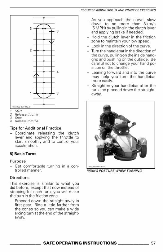
REQUIRED RIDING SKILLS AND PRACTICE EXERCISES
1
2
3
4
3
3
rmo2008-001-046_d
1. Start2. Release throttle3. Stop4. Release throttle
Tips for Additional Practice
– Coordinate releasing the clutchlever and applying the throttle tostart smoothly and to control youracceleration.
5) Basic Turns
Purpose
– Get comfortable turning in a con-trolled manner.
Directions
This exercise is similar to what youdid before, except that now instead ofstopping for each turn, you will makethe turn in the friction zone.
– Proceed down the straight away infirst gear. Ride a little farther fromthe cones so you can make a widearcing turn at the end of the straight-away.
– As you approach the curve, slowdown to no more than 8 km/h(5 MPH) by pulling in the clutch leverand applying brake if needed.
– Hold the clutch lever in the frictionzone to maintain your low speed.
– Look in the direction of the curve.
– Turn the handlebar in the direction ofthe curve, pulling on the inside hand-grip and pushing on the outside. Becareful not to change your hand po-sition on the throttle.
– Leaning forward and into the curvemay help you turn the handlebarmore easily.
– Straighten your handlebar after theturn and proceed down the straight-away.
rmo2008-001-064
RIDING POSTURE WHEN TURNING
______ SAFE OPERATING INSTRUCTIONS ______ 57

REQUIRED RIDING SKILLS AND PRACTICE EXERCISES
1
2
2
3
3
rmo2008-001-046_e
1. Start2. Friction zone3. Apex
NOTE: Motorcyclists - Riding throughturns and curves with your Spyderroadster is different than on a motorcy-cle. The vehicle does not lean duringa turn, so you may need to shift yourbody weight towards the inside of theturn to keep a comfortable postureon the vehicle. You will need to exertmore force to turn the handlebar ofyour vehicle than is needed to turn amotorcycle. However, it is easier tostop while turning than with a motor-cycle.
Tips for Additional Practice
– After you are comfortable turning inone direction, try going around thecourse the other way. Be carefulnot to apply more throttle than youintend when turning left.
– Stop at the apex of the turn to seewhat it is like to use your brakes in acurve or turn.
6) Quick Stops
Purpose
– Become familiar with the vehicle'sbraking ability.
– Learn to apply brakes with maxi-mum force.
Directions
This exercise is similar to what you didbefore, except you’ll be applying thebrake more firmly, working up to brak-ing as hard as possible.
– Start at one end of the straight awayand accelerate to 8 km/h (5 MPH).
– Partway down the straightaway, re-lease the throttle completely andbrake quickly and firmly.
– Keep head and eyes up and keephandlebar straight.
– Repeat, increasing your speed andbraking harder.
2
2
1
rmo2008-001-046_f
1. Start2. Stop
58 _____ SAFE OPERATING INSTRUCTIONS______

REQUIRED RIDING SKILLS AND PRACTICE EXERCISES
Tips for Additional Practice
– Practice checking your mirrors be-fore braking hard.
7) Weaves
Purpose
– Get more experience with the vehi-cle handling and rider position.
Directions
6 m (20 ft) Weave
1. Weave between every marker/in-tersection of every other parkingspot. Do not use throttle — stay inthe friction zone.
2. Lean into each turn and turn thehandlebar in the direction you wantto go by pulling and pushing thegrips.
1
rmo2008-005-050_a
1. Start
12 m (40 ft) Weave
Once you’re comfortable, try doing12 m (40 ft) weaves between everyother cone/every fourth parking space.
1
rmo2008-001-046_k
1. Start
Tips for Additional Practice
– You can gradually increasespeed as you get comfort-able to 16 km/h - 19 km/h(10 MPH - 12 MPH) for the weaves,but slow down for the U-turns at theends.
8) Shifting
When riding, you must change gearsto match the engine speed with roadspeed.
Purpose
– Become familiar with the foot mo-tions needed to shift gears.
– Learn to upshift and downshift.
Directions
This exercise is similar to what you didbefore, except now you will be upshift-ing on the straightaways, then comingto a stop at the end of each straight-
______ SAFE OPERATING INSTRUCTIONS ______ 59

REQUIRED RIDING SKILLS AND PRACTICE EXERCISES
away. You may want to use the parkinglot aisles for this exercise rather thanriding in the spaces.
8a) Practice Using the Shift Lever ata Stop
First, while stopped, practice the leftfoot motion for shifting between firstand second gears.
– At a stop in first gear, pull in theclutch lever.
– Slide the tip of your left foot underthe shift lever and lift it as far as itwill go, one firm stroke up to shiftinto second gear.
– Step on the shift lever and press it asfar as it will go, one firm stroke downto shift into first gear.
– Repeat until you are comfortablewith the foot motions required.
8b) Upshifting from First intoSecond Gear
In the straightaway, accelerate to ap-proximately 16 km/h (10 MPH) in firstgear.
To upshift:
– Release the throttle.
– Pull in the clutch lever. (If you pull inthe clutch before releasing throttle,the engine may rev — just releasethe throttle if this happens.)
– Slide the tip of your left foot underthe shift lever and lift it as far as itwill go, one firm stroke up to shiftinto second gear.
– Smoothly ease out the clutch.
– You do not need to apply throttle,but once you are comfortable, ifspace allows, you can apply thethrottle to increase speed in sec-ond gear.
As you approach the end of thestraightaway, come to a stop:
– Release the throttle.
– Pull the clutch lever all the way in.
– Apply brake.
– After stopping, downshift into firstgear by stepping on the shift leverand pressing it as far as it will go,one firm stroke down. Once youare more comfortable, downshiftinto first as you come to a stop.
1
3 3
3
2
2
rmo2008-001-046_h
1. Start2. Shift into second at 16 km/h (10 MPH)3. Stop
8c) Downshifting from Second toFirst Gear
If space allows, practice downshiftinginto from second to first gear.
In the straightaway, slow to approxi-mately 16 km/h (10 MPH).
– Release the throttle and pull in theclutch lever.
– Step on the shift lever to shift intofirst gear.
– Smoothly ease out the clutch.
– Put your foot back on the peg.
60 _____ SAFE OPERATING INSTRUCTIONS______

REQUIRED RIDING SKILLS AND PRACTICE EXERCISES
8d) Other Gears
If space allows, you can try shifting intoand out of higher gears as well. Followthe same process and shift up or downone gear at a time.
Tips for Additional Practice
As you gain more experience, you canrefine your shifting skills and use themto better control the vehicle.
– When downshifting, rolling on thethrottle slightly while smoothly eas-ing out the clutch can help the en-gine rev up to match vehicle speedmore quickly and make the down-shift smoother, preventing skiddingof the rear wheel.
– Shifting to a lower gear slows thevehicle if you do not apply throttle.This is known as engine braking.To use engine braking, shift downone gear at a time and ease out theclutch between each downshift.Keep the clutch in the friction zoneuntil the engine speed stabilizes,then ease out the lever fully untilready for the next downshift.
– Usually you shift gears one at a time,but it is possible to shift throughmore than one gear while the clutchis squeezed by repeating the up ordown stroke as many times as youwant gear changes.
Remember that VSS does not controlengine braking. If you shift into too lowa gear when you are at high speed, therear tire can skid and you can lose con-trol, spin out, tip or roll over, particularlyin a curve.
9) Swerve
Purpose
– Become familiar with the vehicle’shandling for quick maneuvers.
– Try different variations of brakingand swerving.
Directions
Set up your markers as shown in the di-agram below. Do not use any fixed orhard, heavy objects as markers for thisexercise.
– Enter between the double cones atabout 8 km/h (5 MPH) and maintainthat speed throughout.
– Steer around the line of cones.
– Exit through the second set of dou-ble cones.
– Repeat the exercise multiple times,swerving in both directions.
1
1
3
2
2
rmo2008-001-049_a
1. 6 m (20 ft)2. 3 m (10 ft)3. 2.5 m (8 ft)
Tips for Additional Practice
– You can gradually increaseyour entry speed (to no morethan 13 km/h to 19 km/h(8 MPH to 12 MPH) and try somevariations. For example, approachfaster and slow before entering theexercise, pull in the clutch and applybrakes during the swerve, etc.
______ SAFE OPERATING INSTRUCTIONS ______ 61

REQUIRED RIDING SKILLS AND PRACTICE EXERCISES
– A helper can add an element of sur-prise to the exercise by decidingwhich direction you should swerve,or if you should come to a stop in-stead. Have your helper stand at asafe distance (e.g., beyond the endof your practice area). As you reachthe first set of cones, the helper canuse hand signals to indicate whichdirection to swerve or for you tostop.
– Practice checking your mirrors andblind spot before you swerve.
10) Operating in Reverse
Purpose
– Become familiar with the vehicle’shandling and turning radius in re-verse.
Directions
Shift into reverse. See OPERATINGIN REVERSE in BASIC PROCEDURESsubsection.
Check that the area behind you is clearand continue to look backwards whileyou ease out the clutch. Be carefulnot to strike anything with your frontwheels as you back up. Slow and stopusing clutch and brake, just like whenoperating normally.
Back for a few feet at time, stopping inbetween.
Keep your speed low and do not backup for long distances.
After you are comfortable with re-verse, back into a parking space asshown in the diagram below.
1
3
2
4
rmo2008-001-048_a
1. Start2. Reverse3. Stop4. Forward
Additional Practice in ControlledEnvironments
Once you are comfortable with all ofthe above exercises, you can try a fewother things as space and conditionsallow. This might be in the parking lotor at a later time in a place where youhave the opportunity without puttingyourself at risk.
– Quick starts: Try quickly getting upto speed and upshifting through thegears.
– Quick stop from higher speed:Similar to the quick stop exercise,but performed from higher speedsto get a feel for emergency stops.
– Starting up an incline: To do this,keep holding the brake pedal as yourelease the clutch lever until you arein the friction zone. This will keepyou from rolling backwards.
62 _____ SAFE OPERATING INSTRUCTIONS______

REQUIRED RIDING SKILLS AND PRACTICE EXERCISES
Practice Exercises(SE5 Model)
1) Revving the Engine and Using theEngine Stop Switch
Purpose
– Become familiar with the operationof the twist throttle.
– Become familiar with the sound ofthe engine at different RPMs. Thiswill help you to know when to up-shift and downshift based on theengine sound.
– Become familiar with using the en-gine stop switch.
Directions
– Start with the vehicle in NEUTRAL,the parking brake engaged, and yourright foot on the brake pedal. Checkthe multifunction gauge cluster tobe sure you are in NEUTRAL — ifyou are in first gear, the roadster willtry to start moving when you applythe throttle.
– Watch the tachometer and applythrottle (twist by lowering yourwrist) a few times to raise the RPMto no more than 4000. Practiceapplying the throttle gently andsmoothly, holding it steady at about3000 RPM, and releasing it. As longas the transmission is in neutral thepower will not transfer to the rearwheel.
– Use the engine stop switch to cutall power to the vehicle. Press theswitch with your right thumb whilekeeping your hand on the handgrip.
Tips for Additional Practice
– Practice pressing the engine stopswitch without looking at it.
2) Starting, Stopping and BasicHandling
Purpose
– Learn throttle control and how to getthe vehicle moving.
– Become familiar with low speed de-celeration and braking.
Directions
If you feel like you are losing controlwhile doing these exercises, releasethe throttle to stop accelerating andapply the brake as needed to slowdown. You can also use the enginestop switch to cut power entirely.
2a) Apply and Immediately ReleaseThrottle
Directions
At first, you will only use the throttle fora moment at a time, then release it andcoast.
– Start the engine and release theparking brake.
– With the brake pedal depressed,shift the transmission into first gearby pressing the gear selector for-ward.
– Release the brake.
– Slowly apply throttle until the ve-hicle starts to creep forward. Assoon as you start moving releasethe throttle and coast, then pressthe brake to stop. Repeat to the endof the straightaway.
– To turn around at the end of thestraightaway, stop, turn the han-dlebar all the way to the right, thenbriefly apply and release the throt-tle, and coast through the turn. Youmay need to briefly apply the throt-tle more than once to complete theturn. Stop when you are in line withthe straightaway in the opposite di-rection.
– Continue with this part of the exer-cise until you are comfortable withapplying and releasing the throttle.
______ SAFE OPERATING INSTRUCTIONS ______ 63

REQUIRED RIDING SKILLS AND PRACTICE EXERCISES
2b) Hold Throttle, Release and StopEvery 12 m (40 ft)
Next, you will be holding the throttle alittle longer, then stopping every 12 m(40 ft) (every other marker/every fourthline).
– Again, slowly apply throttle until thevehicle starts to creep forward. Thistime, hold the throttle at this point.
– As you approach the stopping point,release the throttle and press thebrake to stop.
– Turn around at the end of thestraightaway as before, except nowyou do not need to release the throt-tle during the turn. Pay attention tomaintaining a steady throttle posi-tion as you turn. Stop when you arein line with the straightaway in theopposite direction.
2c) Hold Throttle, Release and Stopat Ends
Next, use the entire straightaway,stopping only at the ends. Keep thethrottle moderate.
3) Engine Stop while in Motion
Purpose
– Become familiar with using the en-gine stop switch when in motion soyou know how the vehicle will reactif you need to use it later.
Directions
– Partway down the straightaway,while operating at 8 km/h (5 MPH),turn the engine stop switch to OFFand coast to a stop.
– Restart the engine and repeatthe exercise. Try increasing yourspeed (to a maximum of 20 km/h(12 MPH) before using the enginestop switch.
NOTE: SE5 model will not start in gearwithout brake pedal depressed.
1
2
3
5
4
rmo2008-001-046_c
1. Start2. Press engine stop switch3. Proceed to end of straightaway, stop and
turn as before4. Stop5. Press engine stop switch
Restart the engine and proceed to thenext exercise.
4) Basic Turns
Purpose
– Get comfortable turning in a con-trolled manner.
Directions
This exercise is similar to what youdid before, except that now instead ofstopping for each turn, you will makethe turn at low speed.
– Proceed down the straight away infirst gear. Ride a little farther fromthe cones so you can make a widearcing turn at the end of the straight-away.
– As you approach the curve, slowdown to no more than 8 km/h(5 MPH) by releasing the throttleand apply brake if needed.
64 _____ SAFE OPERATING INSTRUCTIONS______

REQUIRED RIDING SKILLS AND PRACTICE EXERCISES
– Hold the throttle to maintain yourlow speed.
– Look in the direction of the curve.
– Turn the handlebar in the direction ofthe curve, pulling on the inside hand-grip and pushing on the outside, be-ing careful not to apply throttle.
– Leaning forward and into the curvemay help you turn the handlebarmore easily.
– Straighten your handlebar after theturn and proceed down the straight-away.
rmo2008-001-064
RIDING POSTURE WHEN TURNING
1
2
2
3
3
rmo2008-001-046_e
1. Start2. Friction zone3. Apex
NOTE: Motorcyclists - Riding throughturns and curves with your Spyderroadster is different than on a motorcy-cle. The vehicle does not lean duringa turn, so you may need to shift yourbody weight towards the inside of theturn to keep a comfortable postureon the vehicle. You will need to exertmore force to turn the handlebar ofyour vehicle than is needed to turn amotorcycle. However, it is easier tostop while turning than with a motor-cycle.
Tips for Additional Practice
– After you are comfortable turning inone direction, try going around thecourse the other way. Be carefulnot to apply more throttle than youintend when turning left.
– Stop at the apex of the turn to seewhat it is like to use your brakes in acurve or turn.
______ SAFE OPERATING INSTRUCTIONS ______ 65

REQUIRED RIDING SKILLS AND PRACTICE EXERCISES
5) Quick Stops
Purpose
– Become familiar with the vehiclebraking ability.
– Learn to apply brakes with maxi-mum force.
Directions
This exercise is similar to what youdid before, except you’ll be applyingthe brake more firmly, working up tobraking as hard as possible. The An-tilock Braking System (ABS) will pre-vent the wheels from locking and helpyou maintain steering control whileapplying maximum braking force. Al-ways release the throttle completelyfor quick stops with the SE5. If you ap-ply throttle and brake at the same time,your stopping distance will be longer.
– Start at one end of the straightawayand accelerate to 8 km/h (5 MPH).Partway down the straightaway, re-lease the throttle completely andbrake quickly. Never pump thebrake as the ABS will prevent wheellock.
– Keep head and eyes up, keep han-dlebar straight, and do not releasethe brake until fully stopped.
– Repeat, increasing your speed andbraking harder.
2
2
1
rmo2008-001-046_f
1. Start2. Stop
Tips for Additional Practice
– Practice checking your mirrors be-fore braking hard.
6) Weaves
Purpose
– Get more experience with the vehi-cle handling and rider position.
Directions
6 m (20 ft) Weave
1. Weave between every marker/in-tersection of every other parkingspot. Keep your speed low ini-tially as you get used to making thechanges of direction.
2. Lean into each turn and turn thehandlebar in the direction you wantto go by pulling and pushing thegrips.
66 _____ SAFE OPERATING INSTRUCTIONS______

REQUIRED RIDING SKILLS AND PRACTICE EXERCISES
1
rmo2008-005-050_a
1. Start
12 m (40 ft) Weave
Once you’re comfortable, try doing12 m (40 ft) weaves between everyother cone/every fourth parking space.
1
rmo2008-001-046_k
1. Start
Tips for Additional Practice
– You can gradually increasespeed as you get comfort-able to 16 km/h - 19 km/h(10 MPH - 12 MPH) for the weaves,but slow down for the U-turns at theends.
7) Shifting
When riding, you must change gearsto match the engine speed with roadspeed. Lower gears are used for lowerspeeds and higher gears are used forhigher speeds, just like on a manualtransmission car or truck.
The SE5 will not allow you to upshift ifthe engine speed is too low. The SE5will automatically downshift if the en-gine speed drops under 1800 RPM.
Purpose
– Learn to upshift and downshift.
______ SAFE OPERATING INSTRUCTIONS ______ 67

REQUIRED RIDING SKILLS AND PRACTICE EXERCISES
Directions
This exercise is similar to what you didbefore, except now you will be upshift-ing on the straightaways, then comingto a stop at the end of each straight-away. You may want to use the parkinglot aisles for this exercise rather thanriding in the spaces.
7a) Practice Using the Gear Selectorat a Stop
First, while stopped, practice to singleshift between reverse, neutral and firstgear. Then practice to:
– Double shift from reverse to firstgear
– Double shift from first to reversegear
– Repeat until you are comfortable.
7b) Upshifting from First intoSecond Gear
– In the straightaway, accelerateuntil the engine speed reaches3000 RPM.
– Press the gear selector forward toshift into second gear. You do nothave to release the throttle whileshifting with the SE5.
– Once you are comfortable, if spaceallows, you can adjust the throttle toincrease speed in second gear.
As you approach the end of thestraightaway, come to a stop:
– Release the throttle
– Apply brake
– The SE5 will downshift automati-cally as the roadster slows. You canalso manually downshift by pullingthe gear selector towards you.
1
3 3
3
2
2
rmo2008-001-046_h
1. Start2. Shift into second at 25 km/h (16 MPH)3. Stop
7c) If Space Allows, PracticeDownshifting into First WhileMoving
In the straightaway:
– Pull the gear selector toward youwithout releasing throttle.
– You will feel more engine brakingwhen you downshift without throt-tle.
7d) Other Gears
If space allows, you can try shifting intoand out of higher gears as well. Followthe same process and shift up or downone gear at a time.
68 _____ SAFE OPERATING INSTRUCTIONS______

REQUIRED RIDING SKILLS AND PRACTICE EXERCISES
NOTE: Applying slightly more throt-tle while downshifting can help theengine rev up to match vehicle speedmore quickly and make the downshiftsmoother. When you do not applythrottle while downshifting, enginebraking will slow the vehicle. This canhelp you decrease speed, but remem-ber that VSS does not control enginebraking. If you shift into too low a gearwhen you are at high speed, the reartire can skid and you can lose control,spin out, tip or roll over, particularly in acurve.
8) Swerve
Purpose
– Become familiar with the vehicle’shandling for quick maneuvers.
– Try different variations of brakingand swerving.
Directions
At this point you will need to changeyour course. Set up your markers asshown in the diagram below. Do notuse any fixed or hard, heavy objects asmarkers for this exercise.
– Enter between the double cones atabout 8 km/h (5 MPH) and maintainthat speed throughout.
– Steer around the line of cones.
– Exit through the second set of dou-ble cones.
– Repeat the exercise multiple times,swerving in both directions.
1
1
3
2
2
rmo2008-001-049_a
1. 6 m (20 ft)2. 3 m (10 ft)3. 2.5 m (8 ft)
Tips for Additional Practice
– You can gradually increaseyour entry speed (to no morethan 13 km/h to 19 km/h(8 MPH to 12 MPH) and try somevariations. For example, approachfaster and slow before entering theexercise, apply brakes during theswerve, etc.
– A helper can add an element of sur-prise to the exercise by decidingwhich direction you should swerve,or if you should come to a stop in-stead. Have your helper stand at asafe distance (e.g., beyond the endof your practice area). As you reachthe first set of cones, the helper canuse hand signals to indicate whichdirection to swerve or for you tostop.
– Practice checking your mirrors andblind spot before you swerve.
9) Operating in Reverse
Purpose
– Become familiar with the vehiclehandling and turning radius in re-verse.
______ SAFE OPERATING INSTRUCTIONS ______ 69

REQUIRED RIDING SKILLS AND PRACTICE EXERCISES
Directions
– Shift into reverse. See OPERAT-ING IN REVERSE in BASIC PROCE-DURES subsection.
– Check that the area behind you isclear. Continue to look backwards.Be careful not to strike anythingwith your front wheels as you backup. Slow and stop by releasingthrottle and using brake, just likewhen operating normally.
– Back for a few feet at time, stoppingin between.
– Keep your speed low and do notback up for long distances.
– After you are comfortable with re-verse, back into a parking space asshown in the diagram below.
1
3
2
4
rmo2008-001-048_a
1. Start2. Reverse3. Stop4. Forward
Developing AdvancedRiding Skills
Once you have mastered basic ridingskills, you can begin developing moreadvanced skills. First, learn the ”StreetStrategies” covered in the next sec-tion. Then you can take the vehicleon the road in relatively low-risk situa-tions.
Start by riding in less challenging situa-tions:
– Short distances
– Good weather
– Low traffic
– Daytime
– Lower speeds
– No passenger.
You can gradually move on to morechallenging riding situations as you de-velop your skills.
70 _____ SAFE OPERATING INSTRUCTIONS______

STREET STRATEGIES
This section provides some strategiesto reduce your risk on the road. Manyof these strategies are similar to thoseused for motorcycles.
This section is based on guidance formotorcyclists given by the Motorcy-cle Safety Foundation (MSF). How-ever, even experienced motorcyclistsshould read this section, as somestrategies are different for the Spyderroadster.
Plan your Trip
Always check weather conditions be-fore riding the vehicle. Take appropri-ate gear for any weather you mightencounter.
Plan a route and ride in conditions thatare appropriate for your skill level.
The vehicle has a 23.5 L (6.2 U.S. gal.)fuel tank. When the low fuel indicatorlight flashes, fill fuel tank as soon aspossible. Plan your refueling stops,particularly in unpopulated areas.
Defensive Riding
As with a motorcycle, defensive ridingcan help you avoid crashes. You needto stay alert at all times. Never stopwatching your surroundings, includ-ing the area behind you. Always scanfor potential hazards, plan ahead, andleave space and time to avoid trouble.Do not assume other motorists willsee you or follow the rules of the road.
Following Distance
Always leave at least a two-second fol-lowing distance between you and thevehicle in front of you when operat-ing under ideal riding conditions. Thismeans that you should pass any fixedpoint on the road at least two full sec-onds after the vehicle in front of you.
When conditions make braking dis-tance longer, or visibility is limited,use a longer following distance for agreater margin of safety. For example,braking distance is longer on slippery
road surfaces, down hills, or when car-rying more weight, and visibility maybe limited in fog, in curves or at night.
Scanning Ahead
In addition to leaving adequate follow-ing distance to the next vehicle, scanahead and plan your path even fartherin advance.
Plan your immediate path at least fourseconds ahead. Watch this path forhazards, such as anything in the roador anything entering the road.
Scan ahead 12 seconds along your an-ticipated path to identify potential haz-ardous situations before they happen.For example, look for intersectionswhere other vehicles may appear orplaces where pedestrians might enterthe road. Be prepared to respond if ahazardous situation develops.
Watch Behind and to the Sides
Vehicles and other hazards can ap-proach from all directions. Constantlybe aware of your surroundings. Checkyour mirrors frequently to see directlybehind you. Also do frequent headchecks (turn your head to look) to mon-itor your blind spot.
A A
rmo2008-001-014_a
A. Operator's blind spots
______ SAFE OPERATING INSTRUCTIONS ______ 71

STREET STRATEGIES
When braking, be particularly aware ofvehicles behind you that may not beable to stop as quickly as the Spyderroadster.
Keep your Eyes Moving
To stay aware of your surroundings, donot fixate on any one thing. Move youreyes constantly to monitor the road,traffic control markings and devicesand other vehicles. Look near and far,in all directions.
Anticipate Trouble
Whenever you notice a potential haz-ard, plan a way to avoid it. This mightmean adjusting your speed or lane po-sition, or changing lanes. You shouldbe ready for evasive maneuvers suchas swerving and/or braking if some-thing enters your path. Always leavetime and space to react to trouble.
Being Visible
Motorists tend not to see smaller ve-hicles like motorcycles. Therefore youshould use strategies to become morevisible.
To Be More Visible to OtherMotorists
Lighting and Reflectors
Make sure that the headlights, run-ning lights and taillights on your ve-hicle work properly. Your vehicle isequipped with reflectors on the fend-ers, sides, and back. Make sure that allreflectors are clean and not broken ormissing.
Use your high beams whenever pos-sible, both day and night. Use lowbeams to avoid blinding other mo-torists at night or when too much lightreflects back, such as in fog.
Signals
Use your turn signals to inform oth-ers of your intentions. The Spyderroadster has automatic canceling turn
signals, but they may not cancel aftershallow turns. Make sure turn signalsare off after you have completed yourmaneuver; leaving them on may con-fuse other motorists.
When possible, flash your brake lightsbefore slowing and when waiting atintersections, to alert motorists behindyou.
Use your emergency flashers to makeyourself visible when needed.
You can also use your horn to attemptto alert other motorists of your pres-ence.
Do not assume that other motoristswill notice your lights, signals or horn.
Blind Spots
Avoid riding in the blind spots of othervehicles. Position yourself so thatdrivers ahead can see you in their mir-rors. In some cases, such as when youare following a truck or a bus, you mustbe farther behind the vehicle in front ofyou.
A A
rmo2008-001-015_a
A. Blind spots of other vehicles
72 _____ SAFE OPERATING INSTRUCTIONS______

STREET STRATEGIES
Time of Day and Weather
In dim light, such as at night, at dawnor dusk, or in poor weather such as rainor fog, you may be harder to see. Glareat dawn and dusk or very bright sun-light can also make it harder for othermotorists to see you.
Clothing
Bright colors or reflective clothing canincrease your visibility.
Be Careful Even When MotoristsSee You
Even when motorists seem to noticeyou, they may still drive in a way thatputs you at risk of a crash. Drive de-fensively, and do not rely on other mo-torists to operate their vehicles safely.
Lane Position
Normally, position the Spyder roadsterin the center of the lane. This posi-tion keeps the front tires in the lane. Italso provides distance from vehicles inother lanes, reducing wind from largevehicles and reducing the risk of beingstruck by vehicles that leave their lane.This position also keeps your frontwheels out of the slippery area in themiddle of the lane, helping maintainbraking and steering ability. If you areused to driving a car, remember thatyou are centered on the Spyder road-ster, rather than seated to the side, soyour perspective is different.
You can move to the left or right partof the lane, to avoid hazards, keep dis-tance from other vehicles, or handlecurves. You can also move to the leftor right part of the lane to get a bet-ter view or to be seen by other vehi-cles. Because of the Spyder roadstercenter seat position and width, it maybe harder to see around traffic, evenwhen you are near the edge of thelane. You may need a greater followingdistance behind wide or tall vehicles.Avoid putting your wheel outside ofthe lane to see around traffic. In order
for drivers ahead to see you, you mustbe able to see their mirrors. When youare being followed by a large vehicle,passing vehicles may not be able tosee you easily if you are not in the leftpart of the lane.
rmo2008-001-075_a
1. Vehicle in left portion of lane
Because the Spyder roadster is widerthan a motorcycle, the range of lanepositions is smaller. When riding in theleft or right part of the lane be sure thatthe front wheels stay in the lane.
On multilane roads, choose a lane thatis appropriate for your speed in theflow of traffic, and also consider yourability to see and be seen, and possiblepaths for evasive maneuvers (such asswerving into other lanes or onto theshoulder).
Common Riding Situations
Intersections
Intersections, including small inter-sections with alleys and driveways,present an additional risk due to thecross traffic. Always watch for trafficin all directions: behind, in front and tothe left and right.
______ SAFE OPERATING INSTRUCTIONS ______ 73

STREET STRATEGIES
When stopping at an intersection, stopin the middle of the lane, even if youare preparing to turn. This can makeyou more visible and discourage othermotorists from trying to drive aroundyou. Watch for vehicles approachingfrom behind. Flash your brake lights asthey approach. Be in first gear and beprepared to move if necessary to avoida collision.
Lane Changes and Passing
Remember that the Spyder roadsteris wider than a motorcycle and needsmore lateral space to pass another ve-hicle. Also remember that the vehicleis less visible than a car, so it is par-ticularly important to signal your lanechange well in advance and check yourmirrors and blind spots. Be sure toturn off your turn signal after changinglanes; a lane change will not turn thehandlebar far enough to automaticallycancel the signal.
Never drive on the line between twolanes of traffic (split lanes). The vehicleis too wide.
Never drive on the shoulder to passvehicles. If you put one wheel off theroad, you can lose control.
Turns
Remember to slow, look, and steerthrough turns.
– Slow: Reduce speed as needed be-fore entering a turn by rolling off thethrottle, using the brakes, and/ordownshifting to a lower gear. En-ter the turn at a speed that you canmaintain throughout the turn.Although the Spyder roadster is bet-ter able to brake while turning thana motorcycle, it is still important toslow down before you enter a turnor curve rather than braking in theturn. Braking and turning both re-quire traction. The more tractionyou use for braking, the less thereis available for turning at the sametime.When you take a turn or curve toofast, you may notice the inside frontwheel lifting off the pavement andfeel and hear VSS cutting back en-gine power. While VSS can help youmaintain control, it is still possible tospin or roll over if you turn too hardand fast.
– Look: Search through the entireturn and keep your eyes moving.Evaluate the entire turn as soon aspossible — surface characteristics,sharpness of the turn, and overalltraffic conditions — so you havetime to make decisions about speedand position. Sometimes turningyour head in the direction of the turnhelps to keep a good visual picture.
– Steer: Turn the handlebar to steerthe vehicle in the direction of theturn. The Spyder roadster is not likea motorcycle, so it does not counter-steer, and the vehicle does not lean.Remember, you will experience thelateral force generated by turning,so you may need to shift your bodyweight to the inside of the turn tokeep a comfortable posture on thevehicle. You will need to exert moreforce to turn the handlebar of yourvehicle than is needed to turn a mo-torcycle.
74 _____ SAFE OPERATING INSTRUCTIONS______
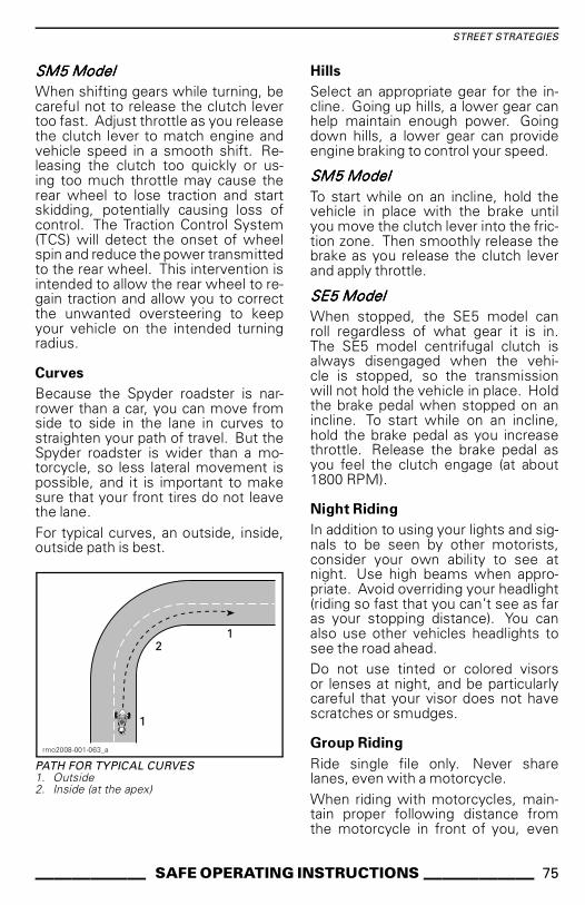
STREET STRATEGIES
SSSSMMMM5555 MMMMooooddddeeeellll
When shifting gears while turning, becareful not to release the clutch levertoo fast. Adjust throttle as you releasethe clutch lever to match engine andvehicle speed in a smooth shift. Re-leasing the clutch too quickly or us-ing too much throttle may cause therear wheel to lose traction and startskidding, potentially causing loss ofcontrol. The Traction Control System(TCS) will detect the onset of wheelspin and reduce the power transmittedto the rear wheel. This intervention isintended to allow the rear wheel to re-gain traction and allow you to correctthe unwanted oversteering to keepyour vehicle on the intended turningradius.
Curves
Because the Spyder roadster is nar-rower than a car, you can move fromside to side in the lane in curves tostraighten your path of travel. But theSpyder roadster is wider than a mo-torcycle, so less lateral movement ispossible, and it is important to makesure that your front tires do not leavethe lane.
For typical curves, an outside, inside,outside path is best.
1
1
2
rmo2008-001-063_a
PATH FOR TYPICAL CURVES1. Outside2. Inside (at the apex)
Hills
Select an appropriate gear for the in-cline. Going up hills, a lower gear canhelp maintain enough power. Goingdown hills, a lower gear can provideengine braking to control your speed.
SSSSMMMM5555 MMMMooooddddeeeellll
To start while on an incline, hold thevehicle in place with the brake untilyou move the clutch lever into the fric-tion zone. Then smoothly release thebrake as you release the clutch leverand apply throttle.
SSSSEEEE5555 MMMMooooddddeeeellll
When stopped, the SE5 model canroll regardless of what gear it is in.The SE5 model centrifugal clutch isalways disengaged when the vehi-cle is stopped, so the transmissionwill not hold the vehicle in place. Holdthe brake pedal when stopped on anincline. To start while on an incline,hold the brake pedal as you increasethrottle. Release the brake pedal asyou feel the clutch engage (at about1800 RPM).
Night Riding
In addition to using your lights and sig-nals to be seen by other motorists,consider your own ability to see atnight. Use high beams when appro-priate. Avoid overriding your headlight(riding so fast that you can’t see as faras your stopping distance). You canalso use other vehicles headlights tosee the road ahead.
Do not use tinted or colored visorsor lenses at night, and be particularlycareful that your visor does not havescratches or smudges.
Group Riding
Ride single file only. Never sharelanes, even with a motorcycle.
When riding with motorcycles, main-tain proper following distance fromthe motorcycle in front of you, even
______ SAFE OPERATING INSTRUCTIONS ______ 75

STREET STRATEGIES
if they are riding to one side of thelane. In curves, do not try to followthe path of motorcycles. Motorcyclescan move farther to the edges of thelane in curves — if you follow them ex-actly, your front wheel can leave thelane. Motorcycles may be able to takecurves faster than the Spyder roadster.Do not try to match their speed.
1
2
rmo2008-001-045_a
GROUP RIDING POSITION
1. Center of lane2. Distance of 2 seconds
Particularly on curvy roads, Spyderroadster riders might become tiredsooner than motorcyclists. Do notpush yourself to keep up with motor-cycles; stop if you are tired.
Road Conditions andHazards
Ice, Snow and Slush
Do not ride on ice, snow or slush. Evenwith VSS, there will not be enoughtraction to maintain control on theseslippery surfaces. The Spyder road-ster is more likely than a car to spin outof control in slippery surfaces.
Gravel, Dirt and Sand
On gravel, dirt, or sand-covered roads,use extra caution and reduce yourspeed, particularly for curves. Thesesurfaces do not provide as much trac-tion as paved surfaces and you canlose control, even with VSS.
Wet Pavement and Puddles
There is normally enough traction tomaintain control on pavement that ismoist or wet, as long as there is nota layer of water on top of the pave-
ment (like a puddle or flowing water onthe road). As with other vehicles, theSpyder roadster can hydroplane if youdrive too fast over water that has accu-mulated on the road, but hydroplaningoccurs at lower speeds than with mostcars or motorcycles. You are morelikely to hydroplane in deeper water.Watch for splashing or spraying whenother vehicles go through water as anindicator of depth.
When hydroplaning occurs, one ormore wheels rise up on a layer of wa-ter, losing contact with the road. If thishappens to the rear wheel, you mayfeel it slide sideways. Hydroplaningwheels do not have the traction nec-essary to control the vehicle. You canlose control and spin out, and the VSScannot keep you in control.
Avoid large water puddles or waterstreams, and slow down or pull off theroad during heavy rains. If you mustpass through water, slow down asmuch as possible before you reach it.
After passing through water, test yourbrakes. Apply them several times ifnecessary to let friction dry the brakepads.
Properly maintained tires reduce therisk of hydroplaning. Always maintainrecommended tire pressure:
COLD TIRE PRESSURE
Front tires103 kPa ± 14 kPa(15 PSI ± 2 PSI)
Rear tires193 kPa ± 14 kPa(28 PSI ± 2 PSI)
NOTE: The pressure difference be-tween the left and right side tire shouldnot exceed 3.4 kPa (.5 PSI).
Immediately replace any tire thatshows the maximum tread wear indi-cator to minimize risk of hydroplaning.
The middle of a lane can be particularlyslick in the first few minutes of rain, asoil and dirt combine with the water. Af-ter more rain, water can accumulate in
76 _____ SAFE OPERATING INSTRUCTIONS______

STREET STRATEGIES
ruts in worn pavement. Avoid both ofthese low traction areas. When possi-ble, keep your front tires in areas withthe best traction.
Off-Road Use
Do not use the Spyder roadster offroad. The vehicle cannot handle therough, low-traction, uneven surfacesthat you may encounter in off-road rid-ing. You could easily get stuck, losecontrol or roll over. Also, it may be ille-gal for off-road use in certain areas.
Obstacles, Holes and Bumps
Whenever possible, avoid riding overobstacles, holes and bumps. If youmust ride over them, slow down asmuch as possible before you get there,then release the brake as you go over.For wide obstacles or bumps, ap-proach straight on if possible, so thatboth front tires go over at the sametime. When going over an obstacle,bump or hole with both front wheels,riders should stand up slightly on thepegs and use legs to absorb the shock.Be prepared for the rear wheel to strikethe obstacle. For narrower obstacles,bumps or holes, it is better to ride overit with the rear tire. If you ride overthem with a front tire, maintain a firmgrip on the handlebar, take care not toaccidentally applying the throttle andbe prepared to correct your trajectoryif necessary.
If you strike a large enough obstacle,bump or hole, the impact can make thevehicle jump and strike you, eject rid-ers, make you lose control, spin or rollover.
If you can’t come to a complete stopin time to avoid an obstacle, you canswerve to avoid it. You can swerveand brake at the same time if neces-sary.
If you encounter a large animal in theroad, like a deer, it is best to stop be-fore reaching it and wait until the ani-mal leaves, or go past slowly. If a dog
chases you, a good strategy is to slowdown and downshift as the dog ap-proaches, then accelerate away as youget closer to where the dog would in-tercept you.
On-Road Emergencies
A vehicle malfunction or an unex-pected situation can occur any timeduring a ride. A well-maintained vehi-cle can help reduce the risk of malfunc-tion, but you should still be preparedfor an emergency.
– Always have the Operator's Guideand tool kit in the vehicle.
– When stopping on the road, followthese precautions:
• If the road has paved shoulders,signal your intention to pull offthe highway, pull off at near traf-fic speed, then slow down to acomplete stop.
• If the shoulder is unpaved, signala right turn and slow down to asafe speed before pulling off thepaved roadway.
• To increase your visibility, turn onthe hazard warning lights.
– If you have cellular phone or othercommunication device, fully chargeit before long rides.
– If you are involved in an accident,BRP strongly recommends that youhave your vehicle transported (seeTRANSPORTING THE VEHICLE) tothe nearest Can-Am roadster dealerto have it thoroughly inspected forsafety before riding again.
– Fill in the BRP accident/incident re-port.
Tire Failure
If a tire failure or a blowout suddenlyoccurs, firmly grip the handlebar, grad-ually slow down and carefully steer to asafe place to stop. Avoid hard braking,downshifting, or sharp steering. If afront tire fails, the vehicle may tend topull in the direction of the failed tire, so
______ SAFE OPERATING INSTRUCTIONS ______ 77

STREET STRATEGIES
you will need to maintain a firm grip onthe handlebar to control your direction.Refer to ROAD SIDE REPAIRS sectionfor instructions on tire repair.
78 _____ SAFE OPERATING INSTRUCTIONS______

CARRYING A PASSENGER OR CARGO
Weight Limits
Do not exceed the weight limits for rid-ers and cargo.
WEIGHT LIMITS
Vehicle load limit(including operator,
passenger, cargo andadded accessories)
208 kg(459 lb)
Front storage compartment16 kg(35 lb)
Excess weight will:
– Reduce your ability to accelerate,brake and turn.
– Reduce the effectiveness of theVSS.
– Increase the risk of rolling over if theweight is high or toward the rear.
– Reduce ground clearance, increas-ing the risk of striking low obstaclesor uneven road surfaces.
– Increase the risk of tire failure.
Operating with ExtraWeight
Carrying a passenger or heavy cargoaffects the way the vehicle handlesbecause of the greater weight, and be-cause the weight distribution will bedifferent.
1. You will not be able to accelerate asquickly. Allow more time and spacefor passing.
2. You will not be able to stop asquickly. Use a longer following dis-tance from the vehicle in front ofyou, at least three seconds. Usean even longer distance if ridingconditions are not ideal (e.g., lowvisibility, poor road surface).
3. You will not be able to turn assharply or at as high a speed. Slowdown more than usual before turn-ing and avoid sharp turns.
4. The Spyder roadster may be lessstable. There is a greater risk of tip-ping or rolling during extreme ma-neuvers with weight that is higheror farther to the rear (like a passen-ger).
Carrying a Passenger
The Spyder roadster is designed foronly one passenger, seated behind theoperator. Never carry multiple passen-gers.
Do not carry a passenger until you haveexperience riding alone in a variety ofconditions and can proficiently handlethe vehicle.
The passenger must be sober, alert,able to reach the passenger footrestsand handholds, maintain balance andhold on in sudden maneuvers, and notdistract the operator.
Be sure the passenger is wearing ap-propriate protective gear. The passen-ger should wear all of the protectivegear recommended for the operator,particularly a helmet. A full-face hel-met is recommended; in a suddenstop, the passenger’s face can strikethe back of the operator's helmet.
Keep the brakes applied and the trans-mission in neutral until the passengeris in riding position.
Instruct the passenger on how to ridebefore starting out. Have the passen-ger follow these rules:
1. Maintain proper riding position.Hold the passenger handholdsand keep feet on the passengerfootrests at all times, even with theaccessory backrest.The passenger should not hold onto the operator as the operator maynot be able to withstand the lateralforce generated by both.Different gripping positions on the
______ SAFE OPERATING INSTRUCTIONS ______ 79

CARRYING A PASSENGER OR CARGO
handholds may be more comfort-able for different maneuvers. (e.g.,one hand at the front corner of andone hand at the opposite back cor-ner for turns, both hands further for-ward or back for other situations).
rmo2008-001-120_a
DIFFERENT GRIPPING POSITIONS ON THEHANDHOLDS
2. Never touch the parking brake pedalwith your left foot. Engaging theparking brake while the vehicle ismoving can cause a crash.
3. Stay clear of the exhaust pipe, therear wheel and the drive belt.
4. Avoid turning around or leaning ex-cept to keep balance in a turn. In anunexpected maneuver, a passengerwho is not in the normal riding posi-tion is more likely to fall off.
5. Watch the road and respond to up-coming road conditions. Lean intocurves as needed to resist any side-ways force. When crossing an ob-stacle, hole or bump, rise slightlyoff the seat without locking your el-bows.
Avoid abrupt acceleration, braking andturns, especially with inexperiencedpassengers. Sudden, unexpected ma-neuvers can make the passenger falloff.
Where to Store Cargo
You can carry cargo in the front storagecompartment. Do not carry cargo inany other location unless the vehicleis equipped with approved BRP acces-sories.
Front Storage Compartment
The front storage compartment hasroom to store light objects, such astwo helmets. Do not put more than16 kg (35 lb) in the front storage com-partment, even if the items fit. Neverstore flammable items, such as fuel, inthe front storage compartment.
Make sure the front storage compart-ment latch is secure before riding.
No Towing
Do not tow anything with the vehicle.The VSS will not be effective, and youwill be more likely to lose control.
80 _____ SAFE OPERATING INSTRUCTIONS______

KNOWLEDGE SELF-TEST
The following provides a sample of in-formation that you should have learnedby reading this guide. It does not in-clude all of the important information,but should give you an idea of whetheryou have a general understanding ofthe vehicle and its operation.
See the ANSWERS on the page follow-ing the questionnaire.
Questionnaire
1111.... If you need to stop quickly, pressboth the brake pedal and theparking brake.
True False
2222.... A pre-ride inspection should beperformed once a week.
True False
3333.... VSS allows you to use the vehiclein any kind of weather.
True False
4444.... You should only replace the tireswith those approved by BRPobtained from an authorizedCan-Am roadster dealer.
True False
5555.... It is important for the passenger tobe alert and sober.
True False
6666.... Name six items of protective gearthat can reduce your risk of injury.
1) _________________________
2) _________________________
3) _________________________
4) _________________________
5) _________________________
6) _________________________
7777.... Protective gear is important forpreventing and reducing injuries,keeping you comfortable, andproviding protection against theelements.
True False
8888.... Which of the following is not oneof the vehicle driving controls?
a. Handlebar
b. Twist throttle
c. Front brake lever
9999.... You should leave your low beamlights on during the day for addedvisibility.
True False
11110000.... You should normally position thevehicle in the center of the lane.
True False
11111111.... Unlike a typical motorcycle, youshould make it common practiceto brake and turn at the sametime.
True False
______ SAFE OPERATING INSTRUCTIONS ______ 81

KNOWLEDGE SELF-TEST
11112222.... Under normal conditions,following distance should beat least ________.
a. 1 second
b. 2 seconds
c. 3 seconds
11113333.... You should not store flammableliquids such as gasoline in thefront storage compartment, evenif they are in approved containers.
True False
11114444.... List 5 ways of being morenoticeable to other drivers.
1) _________________________
2) _________________________
3) _________________________
4) _________________________
5) _________________________
11115555.... When braking on surfaces withless than ideal traction, you shouldpump the brakes to help maintaincontrol of the vehicle.
True False
11116666.... The vehicle’s maximum loadincluding riders, cargo andaccessories is 208 kg (459 lb).
True False
11117777.... The vehicle can safely tow a traileras long as the total towed weightdoes not exceed 200 kg (441 lb).
True False
11118888.... A passenger should hold onto theoperator.
True False
11119999.... Riding the Spyder roadster is assafe as riding in a car.
True False
22220000.... ABS allows you to press thebrake pedal hard without lockingthe brakes.
True False
82 _____ SAFE OPERATING INSTRUCTIONS______

KNOWLEDGE SELF-TEST
Answers
1111.... FFFFaaaallllsssseeeeTo stop quickly, press the brakepedal only. Never use the parkingbrake while the vehicle is moving.
2222.... FFFFaaaallllsssseeee
You should do a pre-ride inspectionevery time you ride.
3333.... FFFFaaaallllsssseeee
If there is ice, snow, slush orenough water on the road tocause hydroplaning, VSS can nothelp you maintain control.
4444.... TTTTrrrruuuueeee
5555.... TTTTrrrruuuueeee
6666.... 1) Helmet
2) Eye and face protection
3) Jacket with long sleeves
4) Gloves
5) Long pants
6) Closed-toe footwear, preferablyover the ankle.
7777.... TTTTrrrruuuueeee
8888.... cccc.... FFFFrrrroooonnnntttt bbbbrrrraaaakkkkeeee lllleeeevvvveeeerrrrThe vehicle does not have a frontbrake lever.
9999.... FFFFaaaallllsssseeee
You should use your high beamsduring the day.
11110000.... TTTTrrrruuuueeee
11111111.... FFFFaaaallllsssseeee
You can brake and turn at the sametime if you need to, but generally itis better to brake before the turn.
11112222.... bbbb.... 2222 sssseeeeccccoooonnnnddddssssUnder normal conditions,following distance should beat least two seconds.
11113333.... TTTTrrrruuuueeee
11114444.... 1) Make sure your lights andreflectors are clean.
2) Use your high beams wheneverpossible.
3) Use your turn signals.
4) Flash your brake lights beforeslowing.
5) Use your emergency flashersas needed.
6) Use your horn to alert others ofyour presence.
7) Avoid riding in blind spots.
8) Wear bright colors andreflective clothing.
11115555.... FFFFaaaallllsssseeeeYou should press and hold thebrake pedal, not pump. Thevehicle is equipped with ABS,which keeps the wheels fromlocking.
11116666.... TTTTrrrruuuueeee
11117777.... FFFFaaaallllsssseeeeYou should never tow a trailerwith the vehicle.
11118888.... FFFFaaaallllsssseeeeThe passenger should alwayshold on to the handholds.
11119999.... FFFFaaaallllsssseeeeIn cars and trucks, the structureof the vehicle providesprotection. In addition,passengers can protectthemselves by wearing seatbelts. You should expect thatriding the Spyder roadster ismuch riskier than riding in a carand that the risk of injury is morelike the risk of injury when ridinga motorcycle.
______ SAFE OPERATING INSTRUCTIONS ______ 83

KNOWLEDGE SELF-TEST
22220000.... TTTTrrrruuuueeee
84 _____ SAFE OPERATING INSTRUCTIONS______

SAFETY INFORMATION ON THE VEHICLE
This vehicle comes with a hang tag andlabels containing important safety in-formation.
Any person who rides this vehicleshould read and understand this in-formation on the vehicle before riding.
Hang Tag
704904124
WARNING
The Spyder roadster is a different type of vehicle -it requires special skills and knowledge.
Learn how the Spyder roadster is different.
Read the operator's guide (in the front storage compartment) and watch the safety video.Complete a training course (if available), practice, become proficient with the controls, and get a proper license.Refer to the Safety Card before riding.
Always wear a helmet and riding gear.With this type of vehicle, riders are exposed to more road risks than in a car. Even skilled operators can be struck by other vehicles or lose control. This vehicle will not protect you in a crash.
Handling limits and road conditionsThe Vehicle Stability System (VSS) cannot stop you from losing control, flipping over, or falling off if you exceed this vehicle’s limits. Know the limits for different road conditions. Do not ride on ice, snow, or off road. Avoid puddles and running water. This type of vehicle can hydroplane on water and slip on gravel, dirt and sand covered roads. If you must go through these road conditions, slow down.
This hangtag may only be removed by the customer.
704904124
______ SAFE OPERATING INSTRUCTIONS ______ 85

SAFETY INFORMATION ON THE VEHICLE
Safety Card
The Safety Card is found at the top of the multifunction gauge cluster. Pull it out toread it, and be sure to securely put it back before riding.
Use the Safety Card to review key information and when you are teaching new op-erators and passengers how to ride the vehicle. It also includes frequently refer-enced information.
NOTE: The following illustration used in this Operator's Guide is a general repre-sentation only. Your model may differ.
Check road conditions.The Vehicle Stability System (VSS) cannot stop
you from losing control, flipping over, or falling off if you exceed this vehicle’s limits.
Know the limits for different road conditions. Do not ride on ice, snow, or off road.
Avoid puddles and running water.This type of vehicle can hydroplane on water and
slip on gravel, dirt and sand covered roads.If you must go through these road conditions, slow down.
Wear a helmet and riding gear.With this type of vehicle, riders are exposed to more road risks than in a car.Even skilled operators can be struck by other vehicles or lose control. This vehicle will not protect you in a crash.
Instruct the passenger.• Always hold handholds and keep feet on pegs.• Watch the road. Lean into curves. Brace for bumps.• Make sure the surrounding is clear and safe before looking at the digital screen.Always keep in mind:• Brake with the foot pedal. Never apply parking brake while moving, you could lose control and crash. • Steer in the direction of a turn; do not countersteer.• Keep all wheels in your lane, always ride in a single lane, and do not split lanes.Perform Pre-ride Inspection
7049
0403
5
704904035
SAFETY CARD
rmo2013-003-008_a
1. Safety card tab location
rmo2014-005-007
TYPICAL - SAFETY CARD PULLED OUT
86 _____ SAFE OPERATING INSTRUCTIONS______
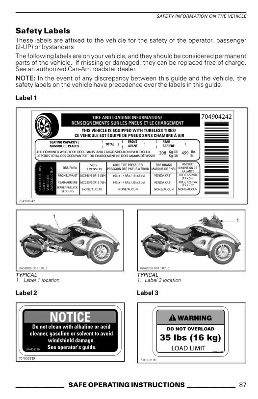
SAFETY INFORMATION ON THE VEHICLE
Safety Labels
These labels are affixed to the vehicle for the safety of the operator, passenger(2-UP) or bystanders
The following labels are on your vehicle, and they should be considered permanentparts of the vehicle. If missing or damaged, they can be replaced free of charge.See an authorized Can-Am roadster dealer.
NOTE: In the event of any discrepancy between this guide and the vehicle, thesafety labels on the vehicle have precedence over the labels in this guide.
Label 1
704904242TIRE AND LOADING INFORMATION/ RENSEIGNEMENTS SUR LES PNEUS ET LE CHARGEMENT
SEATING CAPACITY /NOMBRE DE PLACES TOTAL
REARARRIÈRE2 1 1
THIS VEHICLE IS EQUIPPED WITH TUBELESS TIRES/ CE VÉHICULE EST ÉQUIPÉ DE PNEUS SANS CHAMBRE À AIR
THE COMBINED WEIGHT OF OCCUPANTS AND CARGO SHOULD NEVER EXCEED Kg OR lbsLE POIDS TOTAL DES OCCUPANTS ET DU CHARGEMENT NE DOIT JAMAIS DÉPASSER Kg OU lb
REA
D O
PER
ATO
R’S
GU
IDE
/V
OIR
GU
IDE
DU
CO
ND
UC
TEU
R
FRONT/AVANT
REAR/ARRIÈRE
TIRE/PNEU
SPARE/ PNEU DE SECOURS
SIZE/DIMENSION
COLD TIRE PRESSURE/PRESSION DES PNEUS À FROID
MC165/55R15 55H
TIRE BRANDMARQUE DE PNEU
MC225/50R15 76H
NONE/AUCUN
RIM SIZE/DIMENSION DE
LA JANTE
103 ± 14 kPa / 15 ±2 psi
NONE/AUCUN
193 ± 14 kPa / 28 ±2 psi
KENDA KR31
KENDA KR21
NONE/AUCUN
381 x 127mm (15 x 5)in
381 x 178mm (15 x 7)in
NONE/AUCUN
FRONTAVANT
208 459
704904242
rmo2008-001-107_f
TYPICAL1. Label 1 location
Label 2
704903339
rmo2008-001-107_b
TYPICAL1. Label 2 location
Label 3
704903109
______ SAFE OPERATING INSTRUCTIONS ______ 87

SAFETY INFORMATION ON THE VEHICLE
rmo2008-001-107_e
TYPICAL1. Label 3 located in the front storage
compartment
Label 4
ENGINE OIL AND CERTAIN COMPONENTS IN THE ENGINE
COMPARTMENT MAY BE HOT.
DIRECT CONTACT MAY RESULT IN SKIN BURNS.
Checking Engine Oil Level:
- Make sure engine is at operating temperature.- Roadster must be on a level surface.
- Let engine running at idle for at least 30 seconds.
- Stop engine & wipe the dipstick.
- Dipstick must be screwed in completely before checking oil level.
- Use XPS synthetic blend oil summer grade or equivalent motorcycle oil.
7049
0407
3
CAUTION
704904073
rmo2008-001-029_c
TYPICAL
1. Label 4 located on the oil tank behind theleft middle side panel
Label 5
rmo2008-003-003
COOLANT RESERVOIR CAP
rmo2014-001-006_a
1. Label 5 located underneath right servicecover
88 _____ SAFE OPERATING INSTRUCTIONS______

SAFETY INFORMATION ON THE VEHICLE
Label 6
704903119
rmo2008-001-040_b
TYPICAL1. Label 6 located underneath seat
______ SAFE OPERATING INSTRUCTIONS ______ 89

REPORTING SAFETY DEFECTS
Your safety is very important toBombardier Recreational Products Inc.(BRP). If you have any concerns youshould immediately contact BRP cus-tomer service.
In the USA, if you believe that your ve-hicle has a defect which could causea crash or could cause injury or death,you should immediately inform the Na-tional Highway Traffic Safety Adminis-tration (NHTSA) in addition to notifyingBombardier Recreational Products Inc.
If NHTSA receives similar complaints,it may open an investigation, and if itfinds that a safety defect exists in agroup of vehicles, it may order a re-call and remedy campaign. However,NHTSA cannot become involved in anyindividual problems between you, yourdealer or Bombardier RecreationalProducts Inc.
To contact NHTSA you may either callthe Vehicle Safety Hotline toll-free at888-327-4236 (TTY: 1 800-424-9153) orgo to our website: www.safercar.govor write to:
AdministratorNHTSA400 7th Street SWWashington, DC 20590
You can also obtain other informationabout motor vehicle safety from thethe website www.safercar.gov.
90 _____ SAFE OPERATING INSTRUCTIONS______

PRE-RIDE
INSPECTION
_______________ 91

PRE-RIDE CHECKLIST
WARNINGPerform a pre-ride inspection be-fore each ride to detect potentialproblems during operation. Thepre-ride inspection can help youmonitor wear and deteriorationbefore they become a problem.Correct any problems that you dis-cover to reduce the risk of a break-down or crash. See an authorizedCan-Am roadster dealer as neces-sary.
There is a pre-ride inspection checkliston the Safety Card.
Inspect:
– Tires: Look for damage, incorrectinflation and excessive tread wear.Refer to the MAINTENANCE PRO-CEDURES subsection.
– Wheels and lugnuts: Look fordamage. Twist each front wheellugnut by hand to be sure it is notloose. Be sure the rear wheel axlenut is in place.
– Drive belt: Look for fraying, cuts,punctures and missing teeth. Verifyalignment. For additional informa-tion, refer to the MAINTENANCEPROCEDURES subsection.
– Leaks: Look under the vehicle forany leaks.
– Front storage compartmentcover: Pull to check that it is prop-erly latched.
– Ensure seat is properly latched.
– Mirrors: Clean and adjust (see MIR-RORS in EQUIPMENT subsection).
– Brake pedal: Press and make sureyou feel firm resistance. Pedal mustfully return when released.
– Throttle handle: Twist severaltimes. Be sure it operates freelyand returns to idle position when re-leased.
– Clutch lever (SM5 model): Adjustto your convenience (see PRIMARYCONTROLS subsection). Squeezeto be sure it operates normally andfully returns when released.
– Gearshift selector (SE5 model):Be sure gearshift selector operatesnormally in both directions and re-turns to center when released.
– Weight: Ensure that total load onthe vehicle (including operator, pas-senger, cargo and added acces-sories) does not exceed 208 kg(459 lb).
Turn Ignition Key to the ON Position:
– Multifunction gauge cluster:Check the gauges, indicators, mes-sages and the fuel level.
– Lights: Check operation of head-lights, taillight, brake light, turn sig-nals and hazard warning lights.
– Horn: Check operation.
– Steering: Start engine and verifythat steering operates freely.
– Engine stop switch: Check that theengine stop switch is working prop-erly.
– Parking brake: Start engine, re-lease parking brake and ensure park-ing brake indicator is off on the mul-tifunction gauge cluster.
– Brake: Drive a short distance for-ward slowly then apply brake totest.
Always lock Safety Card back into posi-tion.
92 ______________

MAINTENANCE
_______________ 93

MAINTENANCE SCHEDULE
Maintenance is very important for keeping your vehicle in safe operating condition.Proper maintenance is the owner's responsibility. Perform periodic checks andfollow the maintenance schedule. The maintenance schedule does not exemptthe pre-ride inspection.
WARNINGFailure to properly maintain the vehicle according to the maintenanceschedule and procedures can make it unsafe to operate.
BREAK-IN INSPECTION - 1 000 KM (600 MI)
Using BRP Utility and Diagnostic Software (B.U.D.S.), check fault codes and installrequired updates.
Replace engine oil and oil filter.
Inspect and clean the oil tank strainer.
Replace the Hydraulic Control Module (HCM) oil filter (SE5 model only).
Check engine coolant level.
Inspect throttle twist grip operation.
Check lighting system (brake light, hazard warning light, turn signal lights, positionlights, license plate light).
Check operation of control switches.
Inspect the drive belt condition and its tension. Adjust if required.
Check tightening torque of front wheel lug nuts.
Check tightening torque of the rear wheel axle nut.
Check steering for abnormal play.
Check parking brake operation. Clean and adjust as required.
Check body panels looseness.
Check operation of storage compartment latches, hinges and key barrels.
94 ______________

MAINTENANCE SCHEDULE
MINIMUM MAINTENANCE -IF DRIVING LESS THAN 7 500 KM (4,600 MI) ANNUALLY
Using BRP Utility and Diagnostic Software (B.U.D.S.), check fault codes and installrequired updates.
Using BRP Utility and Diagnostic Software (B.U.D.S.), check pillion rider switchoperation.
Replace engine oil and oil filter.
Replace the Hydraulic Control Module (HCM) oil filter (SE5 model only).
Check clutch fluid level (SM5 model only) (1).
Check radiator, hoses and water pump.
Check engine coolant level (1).
Perform a pressure test of cooling system.
Check reverse mechanism operation. Adjust as required (SM5 model only).
Clean the rear wheel speed sensor. Check the sensor gap. Adjust as required (2).
Inspect throttle twist grip operation.
Check battery connection tightening. Clean them if necessary.
Check lighting system (brake light, hazard warning light, turn signal lights, positionlights, license plate light).
Check operation of control switches.
Inspect the drive belt condition and its tension. Adjust if required.
Check bearing condition of rear sprocket and rear wheel.
Check front wheel bearings condition.
Check tightening torque of front wheel lug nuts.
Check tightening torque of the rear wheel axle nut.
Check steering for abnormal play.
Check tie-rods condition.
Check shock absorbers for leak or other damages.
Check ball joint condition.
Check and/or replace brake fluid (1).
Check brake pads and discs condition.
Check parking brake operation. Clean and adjust as required.
Check tightening of passenger handles.
Lubricate footrest hinges.
_______________ 95

MAINTENANCE SCHEDULE
MINIMUM MAINTENANCE -IF DRIVING LESS THAN 7 500 KM (4,600 MI) ANNUALLY
Check body panels looseness.
Check operation of storage compartment latches, hinges and key barrels and/orlubricate.
(1) Replace every 2 years.(2) Check the gap each time the rear wheel is loosened.
EVERY 500 KM (300 MI)
Check engine oil level.
EVERY 7 500 KM (4,600 MI)
Using BRP Utility and Diagnostic Software (B.U.D.S.), check fault codes and installrequired updates.
Replace engine oil and oil filter.
Replace the Hydraulic Control Module (HCM) oil filter (SE5 model only).
Replace air filter and clean air filter housing (1).
Check clutch fluid level (SM5 model only).
Check engine coolant level.
Inspect throttle twist grip operation.
Check lighting system (brake light, hazard warning light, turn signal lights, positionlights, license plate light).
Check operation of control switches.
Inspect the drive belt condition and its tension. Adjust if required.
Check tightening torque of front wheel lug nuts.
Check tightening torque of the rear wheel axle nut.
Check steering for abnormal play.
Check tie-rods condition.
Check brake fluid level.
Check brake pads and discs condition.
Check parking brake operation. Clean and adjust as required.
Check tightening of passenger handles.
Lubricate footrest hinges.
Check body panels looseness.
(1) Inspection and replacement more frequent when using in dusty or wet areas.
96 ______________

MAINTENANCE SCHEDULE
EVERY 15 000 KM (9,300 MI)
Using BRP Utility and Diagnostic Software (B.U.D.S.), check pillion rider switchoperation.
Check reverse mechanism operation. Adjust as required (SM5 model only).
Clean the rear wheel speed sensor. Check the sensor gap. Adjust as required (1).
Lubricate throttle cable.
Check battery connection tightening. Clean them if necessary.
Check shock absorbers for leak or other damages.
Check brake hoses for cracks or other damages.
Check operation of storage compartment latches, hinges and key barrels and/orlubricate.
(1) Check the gap each time the rear wheel is loosened.
EVERY 22 500 KM (14,000 MI) OR 2 YEARS (WHICHEVER COMES FIRST)
Inspect and clean the oil tank strainer.
Check and adjust valves clearance (1).
Replace air filter and clean air filter housing (2)
Replace clutch fluid (SM5 model only).
Check radiator cap, hoses and water pump.
Perform a pressure test of cooling system.
Replace exhaust pipe joint/gaskets.
Inspect, clean and adjust the throttle body.
Check condition of fuel hoses. Replace as required.
Spark plugs replacement.
Check front wheel bearings condition.
Perform steering alignment.
Check ball joint condition.
Replace brake fluid.
(1) Valve adjustment must be performed more frequently if driving often at high RPM.(2) Inspection and replacement more frequent when using in dusty or wet areas.
EVERY 30 000 KM (19,000 MI) OR 5 YEARS (WHICHEVER COMES FIRST)
Replace the fuel filter.
_______________ 97

MAINTENANCE SCHEDULE
EVERY 45 000 KM (28,000 MI)
Replace engine coolant (or every 5 years).
98 ______________
BREAK-IN INSPECTION
We recommend that after the first 1 000 km (600 mi) of operation, your vehicle beinspected by an authorized Can-Am dealer. The initial maintenance is very impor-tant and must not be neglected.
NOTE: The break-in inspection is at the expense of the vehicle owner.
We recommend that this inspection be signed by an authorized Can-Am dealer.
Date of inspection Authorized dealer signature
Dealer name
_______________ 99

MAINTENANCE PROCEDURES
This section includes instructionsfor basic maintenance procedures.If you have the necessary mechani-cal skills and the required tools, youcan perform these procedures. If not,see your authorized Can-Am roadsterdealer.
Other important items in the mainte-nance schedule that are more difficultand require special tools are best per-formed by your authorized Can-Amroadster dealer.
WARNINGTurn off the engine and followthese maintenance procedureswhen performing maintenance.If you do not follow proper main-tenance procedures you can beinjured by hot parts, moving parts,electricity, chemicals or other haz-ards.
Wheels and Tires
WARNINGTires that are not the recom-mended type, damaged, worndown below the minimum treadwear limit indicator or improperlyinflated can cause loss of control.New tires will not operate at theirmaximum efficiency until theirbreak-in is completed. Braking,steering and VSS performancemay be reduced, so use extracaution. Tires take about 300 km(200 mi) of riding with frequentbraking to break-in. For riding withinfrequent braking, allow extratime to break-in the tires.
The tires have been specifically de-signed for the Spyder roadster. Useonly the BRP recommended tires,which can be ordered only from anauthorized Can-Am roadster dealer.
When the rear tire is removed or re-placed, perform the following:
– Check and clean the rear sprocketbearing. Replace if damaged or bro-ken.
– Check and clean the rear axle bear-ings. Replace if damaged or broken.
– Replace and lubricate the bearingseal of the rear axle.
– Replace and lubricate rear axleO-ring.
– Check and clean the rear axle wearsleeves. Replace if damaged or bro-ken.
When the rear wheel is removed or re-placed, perform the following:
– Replace rear wheel nut.
– Replace and lubricate the bearingseal of the rear axle.
– Replace and lubricate rear axleO-ring.
– Check rubber damper condition.Replace if damaged or broken.
Tire Pressure
Check pressure when tires are coldbefore using the vehicle. Tire pres-sure changes with the air tempera-ture. Recheck pressure if temperaturehas changed (e.g., significant weatherchange, driving in the mountains).
COLD TIRE PRESSURE
Front tires103 kPa ± 14 kPa(15 PSI ± 2 PSI)
Rear tires193 kPa ± 14 kPa(28 PSI ± 2 PSI)
NOTE: The pressure difference be-tween the left and right side tire shouldnot exceed 3.4 kPa (.5 PSI).
For your convenience, an electronicpressure gauge is supplied in the toolkit.
100 ______________

MAINTENANCE PROCEDURES
Tire Damage
Check all tires for:
– Cuts, slits and cracks in the tires.
– Bumps or bulges in the side of thetire or the tread.
– Nails or other foreign objects in theside of the tire or tread.
– Air leaks (hissing sound) caused byan ill-fitting rim or a faulty tire valve.
If any of the above occurs, have the tirerepaired or replaced as soon as possi-ble by an authorized Can-Am roadsterdealer.
Tire Tread Wear
Check minimum tread depth by usingthe tread-wear indicators (hard rubberbars molded at the base of the tread;1 in figure below). Check in three loca-tions across the tire tread:
– Outer edge
– Center
– Inside edge.
The tread-wear indicators will appearacross the treads that have been worndown to the minimum tread depth.When at least one tread-wear indicatorappears across the tread, have the tirereplaced as soon as possible by an au-thorized Can-Am roadster dealer.
rmo2008-001-041_a
TIRE TREAD WEAR1. Tread-wear limit indicator
A. Appropriate tread depthB. Minimum tread depth, replace tire
It is normal to see uneven wear on tiresdepending on how the vehicle is drivenand road conditions. The front tiresexternal or internal edges and the reartire center tread will wear unevenlydepending on if the vehicle is drivensmoothly or aggressively.
WARNINGThe tires are designed to rotateonly in one direction. Do notswitch the left and right frontwheels. If a tire is mounted on theincorrect side, you will have lesstraction and could lose control.
WARNINGDo not hold the front wheel spokewhile attempting to spin the frontwheel as your fingers may becaught between the wheel and thebrake caliper.
Tire Registration Form
In the event of a tire recall, we can onlycontact you if we have your name andaddress. As a vehicle manufacturer,BRP keeps a record of the Tire Iden-tification Number (T.I.N.) associatedwith the Vehicle Identification Number(V.I.N.) (see VEHICLE IDENTIFICA-TION) and its current owner informa-tion.
If you replace any tire on your vehi-cle, a "Tire Registration Form" must becompleted and sent to the tire manu-facturer consumer service group. The“Tire Registration Form” is available atan authorized Can-Am roadster dealer.
Drive Belt
Visually inspect belt alignment andcondition before each ride.
Belt alignment and deflection adjust-ment should always be performed byan authorized Can-Am roadster dealeraccording to the MAINTENANCESCHEDULE.
______________ 101
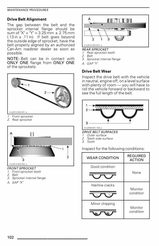
MAINTENANCE PROCEDURES
Drive Belt Alignment
The gap between the belt and thesprocket internal flange should besum of "X" + "Y" = 3.25 mm ± 2.75 mm(.13 in ± .11 in). If belt goes beyondthe outside edge of sprocket, have thebelt properly aligned by an authorizedCan-Am roadster dealer as soon aspossible.
NOTE: Belt can be in contact withONLY ONE flange from ONLY ONEof the sprockets.
rmo2014-003-001_a
1. Front sprocket2. Rear sprocket
rmo2014-003-002_a
FRONT SPROCKET
1. Front sprocket teeth2. Belt3. Sprocket internal flange
A. GAP "X"
rmo2014-003-007_a
REAR SPROCKET1. Rear sprocket teeth2. Belt3. Sprocket internal flange
A. GAP "Y"
Drive Belt Wear
Inspect the drive belt with the vehiclein neutral, engine off, on a level surfacewith plenty of room — you will have toroll the vehicle forward or backward tosee the full length of the belt.
rmo2008-001-109_a
DRIVE BELT SURFACES1. Outer surface2. Teeth side surface3. Tooth
Inspect for the following conditions:
WEAR CONDITIONREQUIRED
ACTION
Good condition
None
Hairline cracksMonitorcondition
Minor chippingMonitorcondition
102 ______________

MAINTENANCE PROCEDURES
WEAR CONDITIONREQUIRED
ACTION
Opened cracks
Replace belt
Hook wear
Replace belt
Missing teeth
Replace belt
Belt fabric worn,exposing internal
componentsReplace belt
Stone damage
Replace belt
NOTE: Hairline cracks do not requirethe replacement of the belt, but mustbe monitored closely — they may leadto opened cracks or missing teeth, re-quiring belt replacement. Damage tothe center of the belt will eventuallyrequire belt replacement, but whencracks extend to the edge of the belt,belt failure is imminent.
When a drive belt is replaced, also re-place the sprockets to increase thelongevity of the new drive belt.
Drive Belt Tension
While riding, if you feel vibrations in thebelt or if the belt is skipping sprocketteeth, have the belt tension adjustedas soon as possible by an authorizedCan-Am roadster dealer.
Engine Oil
NOTICE The procedures for check-ing the Spyder roadster oil level andreplacing oil are different from mostof the motor vehicles today. Prop-erly follow instructions provided inthis section.
Recommended Engine Oil
Use the XPS 4-STROKE SYNTH.BLEND OIL (SUMMER) (P/N 293 600121).
If not available, use SAE 5W 40semi-synthetic or synthetic motorcy-cle oil that meets the requirements forAPI service SL, SJ, SH or SG classifi-cation. Always check the API servicelabel on the oil container.
NOTE: The same oil is used for theengine, gearbox, clutch, and the HCM(SE5 models).
NOTICE To avoid damaging theclutch, do not use a motor oil meet-ing the API service SM or ILSAC GF-4classification. Clutch slippage willoccur.
NOTICE Do not add any oil addi-tives to the recommended oil. Thismay lead to gearbox and clutch mal-functions.
Engine Oil Level Verification
NOTICE To obtain a precise read-ing of the engine oil level, follow thisprocedure and make sure engine isat normal operating temperature.
1. Park the vehicle on a level surface.
2. Remove the LH middle side panel.Refer to BODY PANELS in theEQUIPMENT subsection.
3. With the engine already at normaloperating temperature, start en-gine and let it run for at least 30 sec-onds.
______________ 103
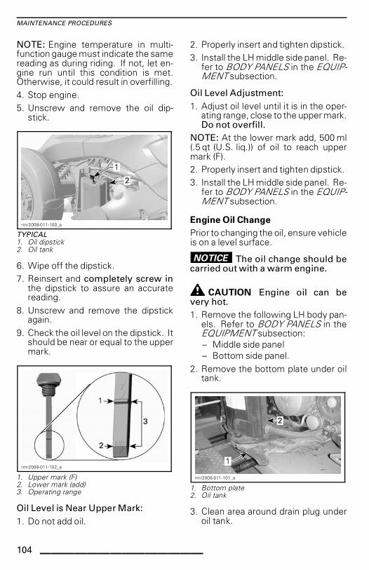
MAINTENANCE PROCEDURES
NOTE: Engine temperature in multi-function gauge must indicate the samereading as during riding. If not, let en-gine run until this condition is met.Otherwise, it could result in overfilling.
4. Stop engine.
5. Unscrew and remove the oil dip-stick.
rmr2008-011-100_a
TYPICAL1. Oil dipstick2. Oil tank
6. Wipe off the dipstick.
7. Reinsert and completely screw inthe dipstick to assure an accuratereading.
8. Unscrew and remove the dipstickagain.
9. Check the oil level on the dipstick. Itshould be near or equal to the uppermark.
rmr2008-011-102_a
1. Upper mark (F)2. Lower mark (add)3. Operating range
Oil Level is Near Upper Mark:
1. Do not add oil.
2. Properly insert and tighten dipstick.
3. Install the LH middle side panel. Re-fer to BODY PANELS in the EQUIP-MENT subsection.
Oil Level Adjustment:
1. Adjust oil level until it is in the oper-ating range, close to the upper mark.Do not overfill.
NOTE: At the lower mark add, 500 ml(.5 qt (U.S. liq.)) of oil to reach uppermark (F).
2. Properly insert and tighten dipstick.
3. Install the LH middle side panel. Re-fer to BODY PANELS in the EQUIP-MENT subsection.
Engine Oil Change
Prior to changing the oil, ensure vehicleis on a level surface.
NOTICE The oil change should becarried out with a warm engine.
CAUTION Engine oil can bevery hot.
1. Remove the following LH body pan-els. Refer to BODY PANELS in theEQUIPMENT subsection:
– Middle side panel
– Bottom side panel.
2. Remove the bottom plate under oiltank.
rmr2008-011-101_a
1. Bottom plate2. Oil tank
3. Clean area around drain plug underoil tank.
104 ______________

MAINTENANCE PROCEDURES
4. Place an appropriate drain pan underoil tank.
5. Remove the tank drain plug and dis-card the sealing washer.
rmr2008-011-103_a
1. Reservoir drain plug2. Oil tank
6. Remove the dipstick.
7. Allow sufficient time for oil to com-pletely drain.
8. Clean area around engine drain plug.
9. Place an appropriate drain pan underthe engine.
10. Remove the engine oil drain plugand discard the sealing washer.
rmr2008-011-104_a
1. Engine oil drain plug2. Oil filter cover
11. Allow sufficient time for oil to com-pletely drain from crankcase.
12. Clean the magnet on the enginedrain plug.
13. Using NEW sealing washers,install engine and oil tank drainplugs.
NOTICE Never reuse the drainplug sealing washer. Always re-place it with a new one.
14. Torque drain plugs (engine and oiltank) to 20 N•m (15 lbf•ft).
15. Replace engine oil filter. Refer toENGINE OIL FILTER REPLACE-MENT further in this section.
SSSSEEEE5555 MMMMooooddddeeeellll
16. Replace HCM oil filter (SE5model). Refer to HCM OIL FIL-TER further in this section.
AAAAllllllll MMMMooooddddeeeellllssss
17. Pour 3 L (3 qt (U.S. liq.)) of the rec-ommended oil into oil tank.
18. Start engine and let idle for twominutes.
NOTICE Do not rev up engine dur-ing idling period as this may causepermanent engine damage.
NOTICE Ensure oil pressure warn-ing lamp goes out within 5 secondsfrom engine start. If oil pressurewarning lamp stays ON for morethan 5 seconds, STOP ENGINE andrecheck oil level.
Check for leaks at:
– Engine oil filter
– HCM oil filter
– Engine drain plug
– Oil tank drain plug.
19. Stop engine.
NOTE: The oil level dipstick is accu-rate when the oil temperature is at80°C (176°F). If the oil level is checkedwhen the oil is at room temperature20°C (68°F), the proper oil level indi-cation is half way between the lower(ADD) and upper (F) marks on the dip-stick. This must be considered to pre-vent overfilling the oil tank.
______________ 105

MAINTENANCE PROCEDURES
SSSSMMMM5555 MMMMooooddddeeeellllssss
20. Add 0.9 L (.95 qt (U.S. liq.)) of therecommended oil in the oil tank(3.9 L (4.1 qt (U.S. liq.)).
21. Check oil level immediately and ad-just if required.
22. Reinstall all removed parts.
23. Dispose of used oil as per your lo-cal environmental regulations.
SSSSEEEE5555 MMMMooooddddeeeellllssss
24. Add 1.2 L (1.3 qt (U.S. liq.)) of therecommended oil in the oil tank(4.2 L (4.4 qt (U.S. liq.)) total quan-tity).
25. Check oil level immediately and ad-just if required.
NOTE: When the engine oil filter andthe HCM oil filter are replaced, thetotal oil quantity to add will be 4.3 L(4.5 qt (U.S. liq.)).
26. Reinstall all removed parts.
27. Dispose of used oil as per your lo-cal environmental regulations.
Engine Oil Filter
Engine Oil Filter Removal
1. Refer to ENGINE OIL CHANGE forremoval of the required s.
2. Remove oil filter cover screws.
rmr2008-011-105_a
TYPICAL1. Oil filter cover2. Cover screws
3. Remove oil filter cover with O-ring.Discard O-ring.
4. Remove oil filter.
5. Dispose of filter as per your local en-vironmental regulations.
Engine Oil Filter Installation
Installation is the reverse of the re-moval procedure. However, pay atten-tion to the following.
1. Check and clean oil inlet and outletorifices in crankcase for dirt and con-taminants.
rmr2008-011-004_a
TYPICAL1. Oil inlet orifice from oil pressure pump2. Oil outlet orifice to engine lubrication system
2. Install a NEW O-ring on the oil filtercover.
To ease assembly and prevent dis-placement of the O-ring during instal-lation, apply a light coat of oil on theoil filter and O-ring. Refer to followingillustration.
rmr2008-011-005_a
1. Apply oil here
HCM Oil Filter (SE5 Model)
The HCM (Hydraulic Control Module)uses the same oil as the engine, buthas its own oil filter.
106 ______________

MAINTENANCE PROCEDURES
NOTICE Replace HCM oil filter andengine oil filter at the same time.
HCM Oil Filter Removal
1. Remove oil filter cover screws.
rmo2013-005-014_a
1. Oil filter cover2. Cover screws
2. Remove oil filter cover with O-ring.Discard O-ring.
3. Remove oil filter.
4. Dispose filter as per your local envi-ronmental regulations.
HCM Oil Filter Installation
The installation is the reverse of the re-moval procedure. Pay attention to thefollowing.
1. Check and clean the oil inlet and out-let orifices in hydraulic control mod-ule for dirt and contaminations.
rmr2008-077-003_a
1. Oil outlet orifice to the hydraulic controlmodule lubrication system
2. Oil inlet orifice to the oil pump
2. Install a NEW O-ring on oil filtercover.
To ease assembly and prevent dis-placement of the O-ring during instal-lation, apply a light coat of oil on theoil filter and O-ring. Refer to followingillustration.
rmo2013-005-013_a
1. Apply oil here
Engine Coolant
Engine Coolant Level Verification
WARNINGWhen opening the reservoir, thecoolant can be very hot and sprayout if the engine is hot. In orderto avoid getting burned, check thecoolant level when the engine iscold.
The cooling system must be filled withdistilled water and antifreeze solution(50% distilled water, 50% antifreeze).
For best performance, use LONG LIFEANTIFREEZE (P/N 219 702 685).
With the engine cold, check thecoolant level as follows:
1. Park the vehicle on a firm, level sur-face.
2. Open the front storage compart-ment.
3. Pull out the right-hand side servicecover with both hands.
4. Check the coolant level on the righthand side. Coolant must be visibleslightly above the COLD. level mark.
______________ 107

MAINTENANCE PROCEDURES
NOTE: If engine is hot, coolant mustbe visible without exceeding the HOT.level mark.
rmo2013-005-001_a
1. Coolant reservoir cap
5. If required, add coolant until it is vis-ible in the reservoir slightly abovethe COLD level mark. Use a funnelto avoid spillage.Do not overfill.
6. Stop adding coolant once coolantstarts to appear in the tube.
rmo2014-001-003_a
1. HOT coolant level reference line
7. Reinstall the service cover.
NOTE: A coolant system that fre-quently requires coolant indicatesleaks or engine problems. See an au-thorized Can-Am roadster dealer.
Brakes
WARNINGNew brakes will not operate attheir maximum efficiency untiltheir break-in is completed. Brak-ing performance may be reduced,so use extra caution. Brakes takeabout 300 km (200 mi) of ridingwith frequent braking to break-in.For riding with infrequent braking,allow extra time to break-in thebrakes.
Brake Fluid Level Verification
Use only DOT 4 brake fluid from asealed container.
Check the brake fluid level as follows:
1. Park the vehicle on a firm, level sur-face.
2. Unlatch and lift the seat.
rmo2008-001-040_b
1. Brake fluid reservoir
3. Check the brake fluid level in bothreservoirs, near the back of the seat.They should both be above the MIN.mark.
108 ______________

MAINTENANCE PROCEDURES
rmo2010-001-091_a
1. Brake fluid MAX. level mark2. Brake fluid MIN. level mark
rmo2010-001-092_a
A. Operating range
4. Remove the filler caps to add fluid.
5. Add fluid as required. Refer toADDING BRAKE FLUID subsection.
NOTE: Low brake fluid may indicateleaks or worn brake pads. See an au-thorized Can-Am roadster dealer.
Adding Brake Fluid
Remove the filler cap.
WARNINGClean filler cap before removing.Use only DOT 4 brake fluid from asealed container.
1. Add fluid to MAX level.
NOTICE Brake fluid can damagepainted surfaces or plastic parts.Wipe up any spills.
2. Reinstall filler cap as follows:
2.1 Check that V slit is in good con-dition.
2.2 Ensure diaphragm are prop-erly positioned.
rbg2008-003-002_a
TYPICAL1. V slit
vmr2008-033-062_a
TYPICAL
1. Correct position2. Wrong position
3. Close the seat and ensure it is fullylatched.
Brake System Verification
The front and rear brakes are hydraulicdisc types. These brakes are self-adjusting and do not require adjust-ment.
The brake pedal also requires no ad-justment.
To keep brakes in good condition,check the following as per the MAIN-TENANCE SCHEDULE:
1. Entire brake system for fluid leaks
2. Brake pedal for spongy feel
3. Brake discs for excessive wear andsurface condition
4. Brake pads for wear, damage orlooseness.
______________ 109

MAINTENANCE PROCEDURES
See an authorized Can-Am roadsterdealer if there are any problems withthe brake system.
Battery
Battery Location
The battery is located in the front stor-age compartment. To access the bat-tery, open the front storage compart-ment.
rmo2008-001-010
FRONT STORAGE COMPARTMENT OPENED
Loosen the screws and open the bat-tery access panel.
rmo2013-003-007_b
TYPICAL1. Screws2. Battery access panel
Battery Charging
The vehicle is equipped with amaintenance-free type battery andis completely sealed; there is no needto add water to adjust the electrolyte
level. The battery may need to becharged if the vehicle has not beenridden for at least one month.
Always have the battery replaced by anauthorized Can-Am roadster dealer.
WARNINGDo not use conventional lead-acidtype batteries. Acid may leak outthrough the battery vent of a con-ventional lead-acid type battery.Acid may also leak if the batterycase is cracked or damaged, whichcan cause severe burns.
The battery can be charged while it isinstalled on the vehicle.
NOTICE Follow the instructionsprovided with your battery charger.Improper charging may damage thebattery.
To charge the battery, proceed as fol-lows:
1. Open the front storage compart-ment.
2. Remove the battery access panel.
3. First connect the POSITIVE (+) cableto the corresponding terminal.
4. Connect the NEGATIVE (-) cable tothe corresponding terminal.
NOTICE Always connect the POS-ITIVE (+) cable first to avoid damag-ing the electrical system of the vehi-cle.
rmo2014-001-001_a
1. NEGATIVE (-) terminal2. POSITIVE (+) terminal
110 ______________

MAINTENANCE PROCEDURES
5. Start the battery charger. Chargingtime will depend on the chargingrate.
When the battery is charged:
6. First disconnect the NEGATIVE (-)cable.
7. Disconnect the POSITIVE (+) cable.
NOTICE Always disconnect theNEGATIVE (-) cable first to avoiddamaging the electrical system ofthe vehicle.
8. Close the battery access panel andthe front storage compartment.
A standard battery charger can beused. The recommended charge rateis 2 A. If the battery is dead, it can bejump started with a car battery (seeROADSIDE REPAIRS section).
For home charging, a “trickle” chargercan be used to slow charge the bat-tery. This type of charger can be leftconnected for a long period of timewithout damaging the battery. Alwaysfollow the charging time as recom-mended in the charger instructions.
Clutch Fluid (SM5 Model)
Clutch Fluid Level Verification
Check the clutch fluid level when theclutch does not operate normally orwhen it is difficult to shift gears withthe gearshift lever.
The clutch fluid reservoir is near the re-verse button on the left handlebar.
Check the clutch fluid level as follows:
1. Park the vehicle on a firm, level sur-face.
2. Set the handlebar straight in order toposition the top of clutch fluid reser-voir horizontally.
3. Wipe clean the cap area.
4. Use the Phillips head screwdriver lo-cated in the toolkit.
5. Unscrew cap retaining screws.
rmo2010-001-005
TYPICAL
6. Carefully remove cap. Pay attentionnot to drop the cap seal.
7. Look inside the reservoir to see thefluid level.
Check clutch fluid level inside thereservoir:
– The fluid must be flush to the filllevel line (protuberance on thereservoir wall).
rmo2013-003-040_a
FLUID REMOVED FOR CLARITY PURPOSE
1. Minimum2. Maximum
Adding Clutch Fluid
1. If the fluid level is lower than spec-ified, add fluid to the reservoir upto the fill level line. Use only DOT 4brake fluid.
2. Add fluid as required. Do not over-fill.
NOTICE Immediately wipe up anyspills.
______________ 111

MAINTENANCE PROCEDURES
3. Push back the seal located insidethe cap.
4. Reinstall the cap to the reservoir.
5. Tighten cap screws.
Headlights
Headlights Aiming
1. Position the vehicle 10 m (33 ft) infront of a test surface as shown.
rmo2012-001-002_a
A. 10 m (33 ft)
90°
rmo2008-027-103_a
2. Trace 2 lines parallel to the groundon the test surface as follows:
LINES ON THE TEST SURFACE
Line 3610 mm (24 in)above ground
Line 2700 mm (27-1/2 in)
above ground
3. Have a person of at least 91 kg(200 lb) taking place on the driver'sseat.
4. Select low beam.
5. Beam aiming is correct when thefocus point (brightest spot) of theheadlight reflection is between themarks.
2
3
1
rmo2008-027-101_a
TYPICAL - HEADLIGHT REFLECTION ON
SURFACE TEST1. Focus point2. Mark at 700 mm (27-1/2 in) above ground3. Mark at 610 mm (24 in) above ground
6. Each headlight can be adjusted byturning the adjustment screws lo-cated in the front of the lower con-sole with a Phillips screwdriver. Ad-just both headlights evenly.
rmr2008-027-102_a
ADJUSTMENT SCREWS
112 ______________

VEHICLE CARE
Vehicle Cleaning
To clean the vehicle, do not usehigh-pressure washers (like the onesfound in car washes) as they may dam-age certain parts of the vehicle.
NOTICE Do not clean the wind-shield with alkaline or acid cleaner,gasoline or solvent to avoid wind-shield damage.
NOTICE For Matte finishes, do notuse wax, detail spray, or other prod-ucts used on regular paint. Do notwash with abrasive materials. Donot use mechanical cleaners or pol-ishers, and do not rub the surfacesvigorously.
To clean the vehicle:
1. Rinse the vehicle thoroughly withwater to remove loose dirt.
2. Using a soft, clean cloth, wash thevehicle with water mixed with a milddetergent, such as soap speciallyformulated for motorcycles or auto-mobiles.
NOTE: Using warm water works wellto remove bugs in the windshield andfront panels.
NOTE: For Matte finishes, hand-washwith a soft wash mitt and a mild clean-ing product safe for matte paint. Toremove foreign substances such as in-sects, use a soft applicator and a mildsolvent. Saturate and soak area beforecleaning. Rub lightly.
3. While washing the vehicle, checkfor grease or oil. You can useXPS ROADSTER WASH (P/N 219701 703) or a mild automotive de-greaser. Thoroughly follow themanufacturer's instructions.
4. Dry the vehicle with a chamois or asoft towel.
NOTE: Vehicles with a matte paint fin-ish may require more frequent clean-ing.
Vehicle Protection
Apply non-abrasive wax to plasticparts.
NOTICE Do not wax or polishmatte surfaces (including mattepaint finishes).
SURFACE RECOMMENDATION
Glossy paintfinishes
Apply only non-abrasivewax, safe for clear
coat paints
Matte paintfinishes
Mattefinishes
Do not apply wax
Windshield can be polished with a plas-tic cleaner/polisher.
NOTICE Do not use water repel-lent products on windshield.
WARNING
Do not apply a vinyl or plastic pro-tector on the seat as the surfacewill become slippery and the oper-ator or the passenger may slip offthe vehicle.
______________ 113

STORAGE AND PRESEASON PREPARATION
Storage
If the vehicle will not be ridden for atleast four months, such as during thewinter, proper storage is necessary tokeep the vehicle in good condition.
BRP recommends you have your au-thorized Can-Am roadster dealer fullyprepare your vehicle for storage. Or, atyour convenience, you can follow thebasic procedures below.
To Prepare the Vehicle for Storage:
1. Inspect vehicle and have your au-thorized Can-Am roadster dealerrepair any problems if necessary.
2. Change the engine oil and filter. Goto an authorized Can-Am roadsterdealer if necessary.
3. Check engine coolant, brake fluidand clutch fluid levels.
4. Fill the fuel tank, add fuel stabi-lizer and run the engine to preventthe tank from rusting and the fuelfrom deteriorating. Strictly followinstructions on fuel stabilizer con-tainer.
5. Inflate all tires to their recom-mended pressure.
6. Clean the vehicle.
7. Lubricate all control cables andlatches, and pivoting points of alllevers.
8. Close and latch all storage compart-ments.
9. Cover the vehicle with a permeablematerials (e.g., tarpaulin). Avoid us-ing plastic or similar non-breathing,coated materials that restrict airflow and allow heat and moistureto accumulate.
10.Store the vehicle in a dry area, awayfrom sunlight, with a small amountof daily temperature variation.
11.Slow charge the battery once amonth at the recommended charg-ing rate of 2 A. It is not necessary toremove the battery.
Preseason Preparation
After a storage period, vehicle must beprepared and inspected.
To Remove the Vehicle from Stor-age:
1. Uncover and clean the vehicle.
2. Charge the battery if needed.
3. Perform a pre-ride inspection, thentest-ride the vehicle at low speed.
114 ______________

ROAD SIDE
REPAIRS
______________ 115

DIAGNOSTIC GUIDELINES
NOTICE If the vehicle must betransported, do not have it towed— towing can seriously damage thevehicle. Refer to TRANSPORTINGTHE VEHICLE in this section for de-tailed instructions.
Will not Shift into FirstGear (SM5 Model)
If the gearbox cannot shift into firstgear when vehicle is not moving:
1. Slowly release the clutch lever whilemaintaining a light pressure downon the shift lever.
2. When you feel the shift lever engag-ing into first gear, pull in the clutchlever.
Will not Shift into Neutral(SE5 Model)
If the gearbox cannot shift into neutralwhen vehicle is not moving:
1. The engine speed will be automat-ically increased to approximately1800 RPM then it will be broughtback to idle speed.
2. Up to 3 attempts will be done.
3. If it does not work, retry pressing up-shift or downshift button.
Will not Shift (SE5 Model)
Have your vehicle transported to thenearest Can-Am roadster dealer.
Engine will not Start
ENGINE DOES NOT TURN OVER
1. Scrolling safety message on themultifunction gauge cluster notacknowledged.
– Press the MODE (M) to acknowl-edge the safety message.
2. Engine stop switch in the OFF po-sition.
– Make sure that the engine stopswitch is in the ON position.
ENGINE DOES NOT TURN OVER(cont’d)
3. Clutch lever not engaged (SM5model).
– Pull in and hold the clutch lever.
4. Ignition switch in the OFF posi-tion.
– Turn the ignition to the ON posi-tion.
5. Battery dead or poor battery con-nections.
– Check the battery charge.Recharge if necessary (seeMAINTENANCE PROCEDURESsubsection).
– Check the battery connections inthe front storage compartment(see MAINTENANCE PROCE-DURES subsection).
6. Blown fuse.
– Check fuse condition (see HOWTO REPLACE FUSES ANDLIGHTS in this section).
7. Transmission is in gear (SE5model).
– Depress brake pedal if transmis-sion is in gear.
ENGINE TURNS OVER, BUT DOES NOTSTART
1. Low fuel.
– Fill the fuel tank (see BASIC PRO-CEDURES subsection).
2. Weak battery.
– Check battery charge. Rechargeif necessary (see MAINTE-NANCE PROCEDURES subsec-tion).
– Check the battery connections inthe front storage compartment .
3. Engine management problem.
– Check to see whether the engineindicator lamp is ON while start-ing. See an authorized Can-Amroadster dealer.
116 ______________

MESSAGES IN MULTIFUNCTION GAUGE
Important information about vehiclecondition is displayed on the multifunc-tion gauge. When starting the engine,always look at the gauge for any indica-tor lamps or special messages.
BBBBaaaasssseeee MMMMooooddddeeeellll
INDICATOR LAMPS (MALFUNCTIONS)
INDICATORLAMP(S)
DIGITALWARNING
CAUSE WHAT TO DO
N R
FLASHING
NoneGearbox
position sensormalfunction
– Stop vehicle and allow to reachneutral.
Have the vehicle transported to thenearest authorized Can-Am roadsterdealer.
None INVALID KEYWrong or
defective key
Use the right key for the vehicleor contact an authorized Can-Amroadster dealer.
ON
HIGH ENGIGETEMPERATURE
Engine isoverheating
– Stop and wait for engineto cool off.
– Check for leaks.
– Check coolant level andadjust (see MAINTENANCEPROCEDURES subsection).
ON
LO BATT VOLTor
HI BATT VOLT
Low or highbattery voltage
– Recharge battery (seeMAINTENANCE PROCEDURESsubsection).
– Check battery connections.Have the vehicle transported to thenearest authorized Can-Am roadsterdealer.
ABSON
ABS FAULTABS
malfunction. NoABS operation
Have the vehicle transported to thenearest authorized Can-Am roadsterdealer.
ONNONE VSS malfunction
* Have the vehicle transported tothe nearest authorized Can-Amroadster dealer.
EBD FAULTEBD
malfunction
Have the vehicle transported to thenearest authorized Can-Am roadsterdealer.
!ON
BRAKE FAILURELow brake fluidlevel or faulty
sensor
– Check for brake fluid leaks.
– Check brake fluid level andadjust (see MAINTENANCEPROCEDURES subsection).
______________ 117

MESSAGES IN MULTIFUNCTION GAUGE
INDICATOR LAMPS (MALFUNCTIONS)
INDICATORLAMP(S)
DIGITALWARNING
CAUSE WHAT TO DO
!
ON+BEEPINGAT KEY OFF
NONEFaulty parking
brake orcomponent
– Make sure battery tension is atleast at 10.5 V.
– Check fuse no. 1 on the rightfuse box (see MAINTENANCEPROCEDURES subsection).
Have the vehicle transported to thenearest authorized Can-Am roadsterdealer.
CHECK ENGINE
Enginemanagementcomponentmalfunction
Remove key, wait 20 seconds, andreinsert key.
CHECK DPS
Dynamicpower steering
componentmalfunction
Have the vehicle repaired by anauthorized Can-Am roadster dealer.
ON
CHECKTRANSMISSION
TransmissionControl Module
componentmalfunction
– Remove key, wait 20 seconds,and reinsert key.
– Have the vehicle repairedby an authorized Can-Amroadsterdealer.
FLASHING
LIMP HOMEMODE
Importantengine
managementcomponent or
VSS malfunction
* Have the vehicle transported tothe nearest authorized Can-Amroadster dealer.
ONNONE Low oil pressure
– Check for oil leaks.
– Check oil level and adjust(see MAINTENANCEPROCEDURES subsection.
Note: A combination of two different warnings can occur.
* BRP recommends having the vehicle transported when in LIMP HOME. If you operatethe vehicle in LIMP HOME, avoid abrupt maneuvers and immediately go to the nearestauthorized Can-Am roadster dealer to have your vehicle serviced before riding again. InLIMP HOME, the engine RPM is limited and therefore the vehicle speed.
118 ______________

MESSAGES IN MULTIFUNCTION GAUGE
RRRRSSSS----SSSS MMMMooooddddeeeellll
INDICATOR LAMPS (MALFUNCTIONS)
INDICATORLAMP(S)
DIGITALINDICATOR
DIGITALWARNING
CAUSE WHAT TO DO
N R
FLASHING
E displayedinstead of
selected gearNONE
Gearboxpositionsensor
malfunction
Stop vehicle andallow to reach neutral.Have the vehicle repairedby an authorized Can-Amroadster dealer.
NONE KEY ERRWrong ordefective
key
Use the right key for thevehicle or contact anauthorized Can-Am roadsterdealer.
ONNONE NONE
Engine isoverheating
– Stop and wait for engineto cool off.
– Check for leaks.
– Check coolant level andadjust (see MAINTE-NANCE PROCEDURESsubsection).
ONNONE NONE
Low orhigh battery
voltage
– Recharge battery(see MAINTENANCEPROCEDURESsubsection).
– Check battery connections.Have the vehicle transportedto the nearest authorizedCan-Am roadster dealer.
ABSON
NONE NONE
ABSmalfunction.
No ABSoperation
Have the vehicle transportedto the nearest authorizedCan-Am roadster dealer.
ONNONE NONE
VSSmalfunction
* Have the vehicletransported to the nearestauthorized Can-Am roadsterdealer.
BRAKEFAILURE OR
!
BRAKEFAILURE
EBDmalfunction
Have the vehicle transportedto the nearest authorizedCan-Am roadster dealer.
!ON BRAKE
FAILURE OR
!
BRAKEFAILURE- LOWBRAKEFLUID
Low brakefluid level orfaulty sensor
– Check for brake fluid leaks.
– Check brake fluid level andadjust (see MAINTE-NANCE PROCEDURESsubsection).
______________ 119

MESSAGES IN MULTIFUNCTION GAUGE
INDICATOR LAMPS (MALFUNCTIONS)
INDICATORLAMP(S)
DIGITALINDICATOR
DIGITALWARNING
CAUSE WHAT TO DO
!
ON+BEEPINGAT KEY OFF
NONE NONE
Faultyparkingbrake or
component
– Make sure battery tensionis at least at 10.5 V.
– Check fuse no. 1 onthe right fuse box(see MAINTENANCEPROCEDURESsubsection).
Have the vehicle transportedto the nearest authorizedCan-Am roadster dealer.
NONE
Enginemanagementcomponentmalfunction
Remove key, wait 20seconds, and reinsert key.
NONE
Dynamicpower
steeringcomponent
Have the vehicle repairedby an authorized Can-Amroadster dealer.
ON
NONE
TransmissionControlModule
component
– Remove key, wait 20seconds, and reinsert key.
– Have the vehicle repairedby an authorizedCan-Amroadster dealer.
FLASHING
LIMPHOME
Importantengine
managementcomponent
or VSSmalfunction
* Have the vehicletransported to the nearestauthorized Can-Am roadsterdealer.
ONNONE NONE
Low oilpressure
– Check for oil leaks.
– Check oil level and adjust(see MAINTENANCEPROCEDURES subsection.
A combination of two different warnings can occur.
* BRP recommends having the vehicle transported when in LIMP HOME. If you operatethe vehicle in LIMP HOME, avoid abrupt maneuvers and immediately go to the nearestauthorized Can-Am roadster dealer to have your vehicle serviced before riding again. InLIMP HOME, the engine RPM is limited and therefore the vehicle speed.
120 ______________

MESSAGES IN MULTIFUNCTION GAUGE
Important information messages canalso be displayed temporarily to assistindicator lamps.
rmo2014-005-028_a
TYPICAL1. Message
When a digital warning appears, it willshow the warning for 6 seconds andthen the warning will disappear for 60seconds. During the 60 seconds, thesmall digital indicator will flash. Thissequence will be repeated three timesand then will stop for 15 minutes. Dur-ing the 15 minutes only the indicatorlamps will be activated.
rmo2014-005-028_b
TYPICAL1. Message/icon
If a fault is displayed, press the MODEbutton to skip the error message.
NOTE: Skipped error messages willstill be displayed in the lower sectionof the multifunction gauge and will bebrought back to the main screen for aperiod of 60 seconds when the vehiclespeed is below 3 km/h (2 MPH)
If a problem persists, go to an autho-rized Can-Am roadster dealer.
______________ 121
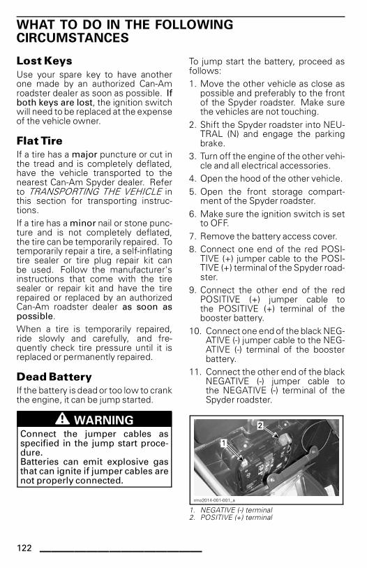
WHAT TO DO IN THE FOLLOWINGCIRCUMSTANCES
Lost Keys
Use your spare key to have anotherone made by an authorized Can-Amroadster dealer as soon as possible. Ifboth keys are lost, the ignition switchwill need to be replaced at the expenseof the vehicle owner.
Flat Tire
If a tire has a major puncture or cut inthe tread and is completely deflated,have the vehicle transported to thenearest Can-Am Spyder dealer. Referto TRANSPORTING THE VEHICLE inthis section for transporting instruc-tions.
If a tire has a minor nail or stone punc-ture and is not completely deflated,the tire can be temporarily repaired. Totemporarily repair a tire, a self-inflatingtire sealer or tire plug repair kit canbe used. Follow the manufacturer'sinstructions that come with the tiresealer or repair kit and have the tirerepaired or replaced by an authorizedCan-Am roadster dealer as soon aspossible.
When a tire is temporarily repaired,ride slowly and carefully, and fre-quently check tire pressure until it isreplaced or permanently repaired.
Dead Battery
If the battery is dead or too low to crankthe engine, it can be jump started.
WARNINGConnect the jumper cables asspecified in the jump start proce-dure.Batteries can emit explosive gasthat can ignite if jumper cables arenot properly connected.
To jump start the battery, proceed asfollows:
1. Move the other vehicle as close aspossible and preferably to the frontof the Spyder roadster. Make surethe vehicles are not touching.
2. Shift the Spyder roadster into NEU-TRAL (N) and engage the parkingbrake.
3. Turn off the engine of the other vehi-cle and all electrical accessories.
4. Open the hood of the other vehicle.
5. Open the front storage compart-ment of the Spyder roadster.
6. Make sure the ignition switch is setto OFF.
7. Remove the battery access cover.
8. Connect one end of the red POSI-TIVE (+) jumper cable to the POSI-TIVE (+) terminal of the Spyder road-ster.
9. Connect the other end of the redPOSITIVE (+) jumper cable tothe POSITIVE (+) terminal of thebooster battery.
10. Connect one end of the black NEG-ATIVE (-) jumper cable to the NEG-ATIVE (-) terminal of the boosterbattery.
11. Connect the other end of the blackNEGATIVE (-) jumper cable tothe NEGATIVE (-) terminal of theSpyder roadster.
rmo2014-001-001_a
1. NEGATIVE (-) terminal2. POSITIVE (+) terminal
122 ______________

WHAT TO DO IN THE FOLLOWING CIRCUMSTANCES
12. Start the vehicle with the boosterbattery and run the engine at anidle of 1200 to 1500 RPM for a cou-ple of minutes.
13. Stand on the right side of theSpyder roadster, apply brakes andstart the engine. If it does notcrank or it cranks slowly, wigglethe jumper cables to make surethey are making good contact andtry again.If it still does not start, there mightbe a problem with the starting sys-tem. Have the vehicle transported(see TRANSPORTING THE VEHI-CLE in this section) and repairedby the nearest authorized Can-Amroadster dealer.
14. As soon the engine starts, discon-nect both jumper cables in the re-verse connection order, startingwith the NEGATIVE (-) cable con-nected to the Spyder roadster.
15. Have the battery fully rechargedwith a battery charger (see MAIN-TENANCE PROCEDURES) or by aqualified service station as soon aspossible.
If the engine dies shortly after it hasbeen jump started or when the jumpercables are disconnected, there mightbe a problem with the charging sys-tem. Have the vehicle transported(see TRANSPORTING THE SVEHICLE)and repaired by the nearest authorizedCan-Am roadster dealer.
After recharging battery, have the vehi-cle inspected by an authorized Can-Amroadster dealer.
______________ 123

HOW TO REPLACE FUSES AND LIGHTS
Fuses
If any electrical accessories stop work-ing on the vehicle, check for blownfuses and replace if necessary.
If an electrical failure still occurs, havethe vehicle serviced by an authorizedCan-Am roadster dealer.
Fuse Locations
Fuses are located inside the front stor-age compartment.
To access the fuse boxes, open thefront storage compartment.
rmo2008-001-010
FRONT STORAGE COMPARTMENT OPENED
Push down on the fuse service coversand pull the covers off.
rmo2013-003-011_a
INSIDE FRONT STORAGE COMPARTMENT1. Left fuse service cover2. Right fuse service cover
Push down on the tabs and carefully re-move the fuse box covers.
rmo2013-005-003_a
1. Tabs2. Fuse box cover
Fuse Description
rmo2013-001-006_a
FUSES - LEFT FUSE BOX
NOTE: Refer to decal located be-tween both fuse boxes for correctidentification.
124 ______________

HOW TO REPLACE FUSES AND LIGHTS
Left Fuse Box
FUSE
NO.DESCRIPTION RATING
1 Cluster / DLC 15 A
2
Wake-up ECM / VCM /MSR and D.E.S.S. / SAS /YAS / PRS
10 A
3
4NOT USED
5 ECM 5 A
6 Injectors / Coils 15 A
7 Wake-up TCM, DPS / Cluster 10 A
8H02S / CAPS / Fuel Pump /EVAP / CSV
15 A
rmo2013-001-005_a
FUSES - RIGHT FUSE BOX
Right Fuse Box
FUSE
NO.DESCRIPTION RATING
1
Days lights /Parking lamps /Plate lights
15 A
2 Brake lights / Hazard 10 A
3
4NOT USED
5 Load shedding 25 A
FUSE
NO.DESCRIPTION RATING
6
7
8
NOT USED
NOTE: When fuse 6 is installed, DCplug is only operational when ignitionswitch is at ON position. When fuse7 is installed, DC plug is always opera-tional.
rmo2013-001-006_c
JCASE FUSES - LEFT FUSE BOX
Left JCase Fuse Box
JCASE
FUSE
NO.
DESCRIPTION RATING
1 VCM pump 40 A
2 VCM pump 25 A
3 DPS 40 A
4 Main control 40 A
5 Cooling fan(s) 30 A
______________ 125

HOW TO REPLACE FUSES AND LIGHTS
rmo2013-001-005_c
JCASE FUSES - RIGHT FUSE BOX
Right JCase Fuse Box
JCASE
FUSE
NO.
DESCRIPTION RATING
1 Rectifier 60 A
2 Accessories 40 A
3 TCM solenoids 20 A
4 LO headlamps 30 A
5 HI headlamps 20 A
Fuse Replacement
1. Set the ignition switch to OFF.
2. Pull the fuse out.
3. Check whether the filament ismelted.
rmo2008-001-060_a
FUSE1. Good fuse2. Blown fuse3. Melted filament
4. Replace the fuse with one with thesame rating. Spare fuses are lo-cated in the fuse box cover.
WARNINGUsing a higher-rated fuse cancause severe damage and maycause fires.
5. To close the fuse box covers, posi-tion covers over fuses and carefullypush down until they click.
6. To close the fuse service covers, po-sition covers over fuse boxes andpush down carefully until the fuseservice covers engage.
7. Close the front storage compart-ment.
Lights
If any light stop working on the vehicle,replace bulb of defective light.
If the light failure still occurs, havethe vehicle serviced by an authorizedCan-Am roadster dealer.
CAUTION Always turn the ig-nition switch to the OFF position be-fore replacing a bulb to avoid electricshock.
Always check light operation after re-placement.
126 ______________

HOW TO REPLACE FUSES AND LIGHTS
rmo2008-001-084_a
LIGHTS LOCATION — FRONT OF VEHICLE
1. Turn signal light2. Headlight3. Position light
rmo2008-001-088_a
LIGHTS LOCATION — REAR OF VEHICLE
1. Taillight/brake light2. Turn signal light3. License plate light
Headlight
1. Insert a small flat head screwdriverin one of the two holes on the upperconsole.
2. Press on the screwdriver and gentlypry out the upper corner of the clus-ter.
3. Insert a finger to maintain the open-ing of the upper corner.
rmo2008-001-121_a
TYPICAL1. Upper console2. Press on the screwdriver inside hole3. Insert finger in opening
4. With the other hand, insert thescrewdriver in the other hole on theupper console.
5. Press on the screwdriver and gentlypry out the other corner of the clus-ter.The upper edge of the cluster will tiltbackward.
rmo2008-001-122_a
1. Insert a finger to maintain the opening ofthe upper corner
2. Press on the screwdriver inside the oppositehole
6. Pull out the housing cap as indicatedbelow.
rmo2008-001-123_a
1. Housing cap
______________ 127

HOW TO REPLACE FUSES AND LIGHTS
7. Turn the connector in the housingcounterclockwise to remove.
8. Remove the bulb by releasing bothclips with a small flat head screw-driver.
rmo2008-001-124_a
1. Bulb housing2. Bulb retaining clip
9. Install the new bulb by clipping it tothe connector.
NOTICE Never touch glass portionof a halogen bulb with bare fingers,it shortens its operating life. If glassis touched, clean it with isopropyl al-cohol and a clean cloth.
10. Install the connector in the bulbhousing and put the housing capon.
11. Install the cluster by first insertingthe bottom edge and then firmlypushing the upper edge with bothhands.
rmo2008-001-125_a
INSTALLING CLUSTER
1. Inserting bottom edge of cluster first andthen pushing the upper edge
12. Ensure the cluster is properly in-stalled. Repeat step 11 if neces-sary.
Turn Signal Light — Front
1. Remove the lens with a Phillipshead screwdriver.
rmo2008-001-103_a
1. Front turn signal lens screw
2. Turn the connector counterclock-wise as indicated below and removelens.
rmo2008-001-104_a
1. Front turn signal light connector
3. Remove the bulb by pushing it inand turning counterclockwise.
4. Install the new bulb by pushing it inand turning clockwise.
5. Properly reinstall the parts in the re-verse order of their removal.
Turn Signal Light — Rear
1. Remove the lens with a Phillipshead screwdriver.
128 ______________

HOW TO REPLACE FUSES AND LIGHTS
rmo2008-001-105_a
1. Rear turn signal lens screw
2. Remove the bulb by pushing it inand turning counterclockwise.
3. Install the new bulb by pushing it inand turning clockwise.
4. Reinstall the lens.
Taillight/Brake Light
1. Remove the wheel well panel by un-screwing 7 Torx screws as indicatedbelow.
rmo2008-001-114_a
WHEEL WELL PANEL
1. 7 Torx screws location
2. Partially remove right rear side panelby removing the 2 plastic rivets un-der the seat as indicated below.
rmo2008-001-115_a
1. 2 plastic rivets under the seat
rmo2008-001-077_a
1. Flat head screwdriver under rivet head2. Turn screwdriver 1/4 turn
rmo2008-001-078_a
1. Flat head screwdriver under rivet2. Turn screwdriver 1/4 turn
3. Disconnect right turn signal housingconnectors.
4. Remove the Torx screw behind thelens as indicated below.
rmo2008-001-116_a
1. Removing Torx screw behind lens
5. Remove the Torx screw beside thelens under the rear tip as indicatedbelow.
______________ 129

HOW TO REPLACE FUSES AND LIGHTS
rmo2008-001-117_a
1. Removing Torx screw beside the lens
6. Turn the connector counterclock-wise and remove from the lens.
rmo2008-001-118_a
1. Connector
7. Remove the bulb by pushing it inand turning counterclockwise.
8. Install the new bulb by pushing it inand turning clockwise.
9. Properly reinstall the parts in the re-verse order of their removal.
NOTE: When installing right rear sidepanel, connect the turn signal housingconnectors by matching the correctwire color and install plastic rivets.
Position Light
BBBBaaaasssseeee MMMMooooddddeeeellllssss OOOOnnnnllllyyyy
1. Push then hold lens towards rear offender.
rmo2008-003-001_a
2. Lift front portion of lens with yourthumb or a small screwdriver to re-lease.
rmo2008-003-002
3. Turn the bulb holder clockwise andremove it from the connector.
rmo2008-001-086_a
1. Turn clockwise
4. Pull bulb out of the holder as indi-cated below.
130 ______________

HOW TO REPLACE FUSES AND LIGHTS
rmo2008-001-087_a
1. Pull out bulb
5. Insert a new bulb in the holder.
6. Properly reinstall the parts in the re-verse order of their removal.
RRRRSSSS----SSSS MMMMooooddddeeeellllssss OOOOnnnnllllyyyy
The position lights are built with LEDs(light emitting diode) and this tech-nology proved to be reliable. In theunlikely event they do not work,have them checked by an authorizedCan-Am roadster dealer.
License Plate Light
1. Remove the lens with a Phillipshead screwdriver.
rmo2008-001-090_a
1. License plate lens screw
2. Remove the bulb by pushing it inand turning counterclockwise.
3. Install the new bulb by pushing andturning it clockwise.
4. Reinstall the lens.
______________ 131

TRANSPORTING THE VEHICLE
If your vehicle needs to be transported,it should be carried on a flatbed trailerof the proper size and capacity.
CAUTION If you need to pushthe vehicle, do it from the right-handside to be able to reach the brakepedal.When pulling the vehicle back-wards, be careful that the frontwheel does not roll over your feet.
NOTICE Do not tow the Spyderroadster — towing can seriouslydamage the vehicle drive system.
When contacting a towing or trans-porting service, be sure to ask if theyhave a flatbed trailer, loading ramp orpower ramp to safely lift the vehicleand tie-down straps. Ensure the vehi-cle is properly transported as specifiedin this section.
NOTICE Avoid using chains to tiethe vehicle — they may damagethe surface finish or plastic com-ponents.
To load the vehicle for transport, pro-ceed as follows:
1. Shift the vehicle into NEUTRAL (N).
2. Remove the key from the ignitionswitch.
3. Put a strap around the lower arm ofeach front suspension.
rmo2008-001-065_a
TYPICAL
1. Strap2. Lower suspension arm
4. Attach the straps to the winch cable.If possible, use chains or additionalstraps to attach the straps to thewinch cable as indicated below toavoid damaging the bumper cover.
rmo2008-001-066_a
1. Strap around front suspension lower arms2. Chains to avoid damaging the bumper cover3. Winch cable
5. Ensure that the parking brake is re-leased.
6. Pull the vehicle on the flatbed trailerwith the winch.
7. Engage the parking brake.
8. Ensure that the vehicle is in NEU-TRAL (N).
9. Strap the front tires by using one thefollowing methods indicated below.
rmo2008-001-069_a
FRONT WHEELS ATTACHMENT —
METHOD 11. Strap around the rim of each front wheel
and attached to the front of trailer
132 ______________

TRANSPORTING THE VEHICLE
rmo2008-001-073_a
FRONT WHEELS ATTACHMENT —
METHOD 21. Strap around each wheel and fixed to the
front and rear of trailer
10. Pass a tie-down strap inside therear wheel rim only. Do not passthe tie-down strap inside the rearsprocket.
NOTICE Passing the tie-downstrap inside the rear sprocket mayseriously damage the drive system.
rmo2008-001-067_a
REAR WHEEL ATTACHMENT1. Tie-down strap2. Inside rear wheel rim ONLY
11. Firmly attach the rear wheeltie-down strap to the rear of thetrailer with a ratchet.
12. Ensure that both the front and rearwheels are firmly attached to thetrailer.
rmo2008-001-072_a
1. Front and rear wheel firmly attached totrailer
______________ 133

TRANSPORTING THE VEHICLE
This page is
intentionally blank
134 ______________

TECHNICAL
INFORMATION
______________ 135

VEHICLE IDENTIFICATION
The main components of your vehicle(engine and frame) are identified bydifferent serial numbers. It may some-times become necessary to locatethese numbers for warranty purposesor to trace your vehicle in the eventof loss. These numbers are requiredby the authorized Can-Am roadsterdealer to complete warranty claimsproperly. No warranty will be allowedby Bombardier Recreational ProductsInc. if the engine identification number(EIN) or vehicle identification number(VIN) is removed or mutilated in anyway. We strongly recommend thatyou take note of all the serial numberson your vehicle and supply them toyour insurance company.
Vehicle IdentificationNumber
1 2
rmo2008-001-091_a
VEHICLE SERIAL NUMBER LABEL1. VIN (Vehicle Identification Number)2. Model number
rmo2008-001-029_e
TYPICAL - LOCATION OF VIN1. Swing arm (VIN label)2. Lower frame (VIN stamped on the right side)
Engine IdentificationNumber
rmo2008-001-111_a
TYPICAL1. EIN (Engine Identification Number) location
EPA Compliance Label(USA)
rmo2008-001-094
LOCATED UNDER THE SEAT
136 ______________

SPECIFICATIONS
MODEL SPYDER RS
ENGINE
ROTAX 991 60° V-Twin
Engine type 4-stroke, Dual Over Head Camshaft(DOHC), liquid cooled
Number of cylinders 2
Number of valves 8 valves
Bore 97 mm (3.82 in)
Stroke 67.5 mm (2.6575 in)
Displacement 998 cm³ (60.9 in³)
Compression ratio 12,2:1
Type Dry sump with separate oil tank and oil cooler
Engine BRP Rotax microglass fibre type, replaceableOil filter
Transmission SE5 BRP Rotax microglass fibre type, replaceable
Oil change withnew engine filter
SM5 3.9 L (4.1 qt (U.S. liq.))
Oil change withnew engine filter
4.2 L (4.4 qt (U.S. liq.))Engine oilcapacity
Oil change withnew engine andHCM filters
SE5
4.3 L (4.5 qt (U.S. liq.))
Lubrication
Recommended engine oil
Use XPS 4-STROKE SYNTH. BLEND OIL(SUMMER) (P/N 293 600 121) or a 5W 40
semi-synthetic (minimum) or synthetic motorcycleoil meeting the requirements for API service
SL, SJ, SH or SG classification
TypeWet, multi-plate, manual operation through
a hydraulic piston, vacuum assist
Fluid
SM5
DOT 4 brake fluid
TypeCentrifugal clutch + wet multi-plate clutch
automatically controlled by TCM
Engagement 2000 +/- 200 RPM (centrifugal)
Clutch
Stall
SE5
3200 +/- 200 RPM (centrifugal)
Exhaust system 2 into 1 with catalytic converter
Air filter Paper element
______________ 137

SPECIFICATIONS
MODEL SPYDER RS
GEARBOX
SM5Sequential Manual 5-speed (SM5) with remote
electronic reverse interlockType
SE5Sequential Semi-automatic 5-speed (SE5) with
remote electronic reverse interlock
COOLING SYSTEM
Type Liquid cooled, single radiator with cooling fan
Type
Ethyl glycol/water mix (50% coolant, 50% distilledwater). Use premixed coolant sold by BRP LONGLIFE ANTIFREEZE (P/N 219 702 685) or coolant
specifically designed for aluminum enginesCoolant
Capacity 3.15 L (3.3 qt (U.S. liq.))
ELECTRICAL SYSTEM
Magneto generator output 500 W
Ignition system type Electronic ignition with dual output coil
Ignition timing Not adjustable
Quantity 2
Make and typeNGK KR8Bi (apply heat-sink paste P12 (P/N 420
897 186) on spark plug threads)Spark plug
Gap 0.7 mm - 0.8 mm (.028 in - .031 in)
Engine RPM limiter setting Forward 9500 RPM
Type Yuasa YTX24HL-BS
Voltage 12 volts
Nominal rating 21 A•hBattery
Recommended chargingrate
2 A
Headlight 2 x 55 W
Taillight/brake light 2 x 5/21 W
Front 2 x 21 WTurn signal lights
Rear 2 x 10 W
Position lightsBasemodel
2 x 5 W
License plate light 10 W
FusesRefer to FUSES in HOW TO REPLACE
FUSES AND LIGHTS
138 ______________

SPECIFICATIONS
MODEL SPYDER RS
FUEL SYSTEM
Fuel delivery TypeMulti-point Electronic Fuel Injection (EFI)
with ETC (Electronic Throttle Control)dual 51 mm throttle body with an actuator
Fuel pump Type Electrical module in fuel tank
Idle speed 1400 ± 100 RPM (not adjustable)
Type Premium unleaded gasoline
87 Pump Posted AKI (RON+MON)/2Minimum octane
92 RON
91 Pump Posted AKI (RON+MON)/2
Fuel - Refer toFUEL REQUIRE-MENTS
Recommended octane95 RON
Fuel tank capacity 23.5 L (6.2 U.S. gal.)
DRIVE SYSTEM
Final drive type Carbon reinforced drive belt
Final drive ratio 28/79
STEERING
Type Dynamic Power Steering (DPS)
FRONT SUSPENSION
Suspension type Double A-arm with anti-sway bar
RS 151 mm (5.94 in)Suspension travel
RS-S 142 mm (5.59 in)
Qty 2
RS SACHS twin-tube coil-overShock absorberType
RS-S FOX mono-tube coil cover
RS No adjustmentSpring preload adjustment
RS-S Threaded rings
REAR SUSPENSION
Suspension type Swing arm with monoshock
Suspension travel 152 mm (5.98 in)
Qty 1Shock absorber
Type SACHS twin-tube coil-over
Spring preload adjustment No adjustment
______________ 139

SPECIFICATIONS
MODEL SPYDER RS
BRAKES
Type Brembo
Front brake
Dual270 mm (11 in) rigid discs,
radially mounted Brembo monoblocwith 4 piston calipers, 2-pad
Rear brake
Single270 mm (11 in) disc
with 1 piston floating caliper withintegrated parking
Capacity 545 ml - 570 ml (18.4 U.S. oz - 19.3 U.S. oz)Brake fluid
Type DOT 4
Parking brake Foot operated, self-adjust
Minimum brake pad thickness 1 mm (.04 in)
Minimum brake disc thickness 6.4 mm (.252 in)
Maximum brake disc warpage 0.100 mm (.004 in)
TIRES
Front Kenda KR31 165/55R15Type (use only tiresrecommended by BRP) Rear Kenda KR21A 225/50R15
Nominal.: 103 kPa (15 PSI)Min.: 89 kPa (13 PSI)
Max.: 117 kPa (17 PSI)Front
NOTE: The pressure difference between theleft and right side tire should not exceed 3.4 kPa(.5 PSI).
Pressure
RearNominal.: 193 kPa (28 PSI)
Min.: 179 kPa (26 PSI)Max.: 207 kPa (30 PSI)
Front 2.5 mm (3/32 in)Minimum tire tread depth
Rear 4.0 mm (5/32 in)
WHEELS
Front 381 mm (15 in) x 127 mm (5 in)Size (diameter X width)
Rear 381 mm (15 in) x 178 mm (7 in)
Front wheel nuts torque 105 N•m to 113 N•m (77 lbf•ft to 83 lbf•ft)
Rear drive axle nut torque 210 N•m to 240 N•m (155 lbf•ft to 177 lbf•ft)
140 ______________

SPECIFICATIONS
MODEL SPYDER RS
DIMENSIONS
Overall length 2 667 mm (105 in)
Overall width 1 506 mm (59.3 in)
Overall height 1 146 mm (45.1 in)
Seat (top) height 737 mm (29 in)
Wheel base 1 711 mm (67.4 in)
Front wheel track 1 308 mm (51.5 in)
Ground clearance, front and under engine 110 mm (4.3 in)
WEIGHT AND LOADING CAPACITY
Dry weight 362 kg (798.1 lb)
Capacity 58 L (15.32 U.S. gal.)
Front storage compartmentMaximum load 16 kg (35 lb)
Total vehicle load allowed (including operator, all otherloads and added accessories)
208 kg (459 lb)
Gross vehicle weight rating (GVWR) 593 kg (1,307 lb)
Because of our ongoing commitment to product quality and innovation, BRP reserves theright, at any time, to make changes in design and specifications and/or to make additions to,or improvements in its products without imposing any obligation upon itself to install themon its previously manufactured products.
______________ 141

SPECIFICATIONS
This page is
intentionally blank
142 ______________

WARRANTY
______________ 143

BRP LIMITED WARRANTY — USA AND CANADA:2014 Can-Am® SPYDER® ROADSTER
1. SCOPE OF THE LIMITED WARRANTY
Bombardier Recreational Products Inc. (“BRP”)* warrants its 2014 Can-AmSpyder Roadsters ("Roadster") sold by authorized Can-Am Roadster Dealers (asdefined below) in the United States of America and in Canada from defects inmaterial or workmanship for the period and under the conditions described below.This limited warranty will become null and void if: (1) Roadster was used for racingor any other competitive activity, at any point, even by a previous owner; (2) theodometer was removed or has been tempered with; (3) the Roadster was usedoff-road; or (4) the Roadster has been altered or modified in such a way so as toadversely affect its operation, performance or durability, or has been altered ormodified to change its intended use.
Except if otherwise specified, all genuine Roadster parts and accessories installedon the Roadster by an authorized Dealer at the time of delivery of the Roadstercarry the same warranty as that of the Roadster.
2. LIMITATIONS OF LIABILITY
THIS WARRANTY IS EXPRESSLY GIVEN AND ACCEPTED IN LIEU OF ANYAND ALL OTHER WARRANTIES, EXPRESSED OR IMPLIED, INCLUDINGWITHOUT LIMITATION ANY WARRANTY OF MERCHANTABILITY OR FIT-NESS FOR A PARTICULAR PURPOSE. TO THE EXTENT THAT THEY CANNOTBE DISCLAIMED, THE IMPLIED WARRANTIES ARE LIMITED IN DURATIONTO THE LIFE OF THE EXPRESS WARRANTY. INCIDENTAL AND CONSE-QUENTIAL DAMAGES ARE EXCLUDED FROM COVERAGE UNDER THISWARRANTY. SOME STATES/PROVINCES DO NOT ALLOW FOR THE DIS-CLAIMERS, LIMITATIONS AND EXCLUSIONS IDENTIFIED ABOVE, AS ARESULT, THEY MAY NOT APPLY TO YOU. THIS WARRANTY GIVES YOUSPECIFIC RIGHTS, AND YOU MAY ALSO HAVE OTHER LEGAL RIGHTSWHICH MAY VARY FROM STATE TO STATE, OR PROVINCE TO PROVINCE.
Neither the distributor, any Dealer nor any other person has been authorized tomake any affirmation, representation or warranty regarding the Roadster, otherthan those contained in this limited warranty, and if made, shall not be enforceableagainst BRP. BRP reserves the right to modify this warranty at any time, beingunderstood that such modification will not alter the warranty conditions applicableto the Roadsters sold while this warranty is in effect.
3. EXCLUSIONS — ARE NOT WARRANTED
The following are not warranted under any circumstances:
– Replacement of routine maintenance items such as, without limitation, oil, lu-bricants, fluids, filters and spark plugs.
– Normal wear and tear, such as, without limitation, wear and tear of the tires, bat-tery, generator brushes, sealed beams and light bulbs, clutch plates and facings,drive belt, brake pads, brake linings and rotors and sprockets.
– Tune ups and adjustments including without limitation adjustments of belt,alignment and wheel balance.
– Damages related to the appearance of the Roadster, including without limitationscratches, dents, fading, flaking, peeling and damages to seat cover material.
144 ______________

– Damage caused by failure to provide proper maintenance or storage, as de-scribed in the OPERATOR'S GUIDE.
– Damage resulting from removal of parts, improper repairs, improper service orimproper maintenance, modifications, alterations that are outside of the originalspecifications of the Roadster, or damage resulting from repairs done by a per-son that is not an authorized servicing Dealer.
– Damage resulting from the installation of parts with specifications that differfrom the original Roadster parts, such as, without limitation, different tires,exhaust system, wheels or brakes.
– Damage resulting from abuse, abnormal use, neglect or operation of the Road-ster in a manner inconsistent with the recommendations of the OPERATOR'SGUIDE.
– Damage resulting from water ingestion, accident, road hazards, submersion,fire, theft, vandalism or any act of God.
– Damage resulting from operation with fuels, oils or fluids with specifications dif-ferent than as recommended in the OPERATOR'S GUIDE.
– Damage resulting from corrosion from road salts, battery acid, environmentalinfluences or treatment contrary to the OPERATOR'S GUIDE.
– Incidental or consequential damages, including without limitation towing,storage, telephone, rental, taxi, inconvenience, insurance coverage, loanpayments, loss of time or loss of income.
4. WARRANTY COVERAGE PERIOD
This warranty will be in effect from the date of delivery to the first retail consumeror the date the Roadster is first put into use, whichever occurs first and for thefollowing periods:
1. For private, recreational use, TTTTWWWWEEEENNNNTTTTYYYY FFFFOOOOUUUURRRR ((((22224444)))) CCCCOOOONNNNSSSSEEEECCCCUUUUTTTTIIIIVVVVEEEE MMMMOOOONNNNTTTTHHHHSSSS,except for the items covered in points (2) to (5) below; and for commercialuse TTTTWWWWEEEELLLLVVVVEEEE ((((11112222)))) CCCCOOOONNNNSSSSEEEECCCCUUUUTTTTIIIIVVVVEEEE MMMMOOOONNNNTTTTHHHHSSSS, except for the items covered inpoints (2) to (5) below.
A Roadster is used commercially when it is used in connection with any workor employment that generates income during any part of the warranty period.A Roadster is also used commercially when, at any point during the warrantyperiod, it is licensed for commercial use.
2. For the battery, SSSSIIIIXXXX ((((6666)))) CCCCOOOONNNNSSSSEEEECCCCUUUUTTTTIIIIVVVVEEEE MMMMOOOONNNNTTTTHHHHSSSS.
3. For the tires, 6666 CCCCOOOONNNNSSSSEEEECCCCUUUUTTTTIIIIVVVVEEEE MMMMOOOONNNNTTTTHHHHSSSS or until tires are worn to the lastthree thirty-seconds of an inch (3/32 ") (2.38 millimeters) for the front tires andthe last five thirty-seconds of an inch (5/32 ") (3.97 millimeters) for the rear tire,whichever occurs first.
4. For Roadsters sold to residents of the United States, FFFFIIIIVVVVEEEE ((((5555)))) YYYYEEEEAAAARRRRSSSS oooorrrrTTTTHHHHIIIIRRRRTTTTYYYY TTTTHHHHOOOOUUUUSSSSAAAANNNNDDDD ((((33330000 000000000000)))) KKKKIIIILLLLOOOOMMMMEEEETTTTEEEERRRRSSSS ((((11118888,,,,666644441111 MMMMIIIILLLLEEEESSSS)))), whicheveroccurs first, on the emission related components included in the chart below.
______________ 145

WARRANTY EMISSION PART LIST
Oxygen sensor Oil filler cap
Intake manifold Catalytic converter
Ignition coil Rear exhaust manifold
Spark plug wire (front cylinder) Front exhaust manifold
Spark plug wire (rear cylinder) Fuel return hose
Fuel tank Evaporative emission control system (EVAP)
Fuel tank cap Engine control module (ECM)
5. For Roadsters produced for sale in the state of California, that are originallysold to residents or subsequently warranty registered to residents in thestate of California, please also refer to the applicable California EmissionsControl Warranty Statement.
The repair or replacement of parts or the performance of service under thiswarranty does not extend the life of this warranty beyond its original expirationdate.
5. CONDITIONS TO HAVE WARRANTY COVERAGE
This warranty coverage is available only if each of the following conditions hasbeen fulfilled:
– The Roadster must be purchased as new and unused by its first owner froma Spyder Roadster dealer authorized to distribute Roadsters in the country inwhich the sale occurred (“Dealer”).
– The BRP-specified pre-delivery inspection process must be completed, docu-mented and signed by the purchaser.
– The Roadster must have undergone proper warranty registration by an autho-rized Dealer.
– The Roadster must be purchased in the country in which the purchaser resides.
– Routine maintenance must be performed as indicated in the OPERATOR'SGUIDE. BRP reserves the right to make warranty coverage contingent uponproof of proper maintenance.
BRP will not honor this limited warranty to any private use owner or commercialuse owner if the preceding conditions have not been met. Such limitations arenecessary in order to allow BRP to preserve both the safety of its products, andalso that of its consumers and the general public.
6. WHAT TO DO TO OBTAIN WARRANTY COVERAGE
The customer must cease using the Roadster upon the appearance of an anom-aly. The customer must notify a servicing Dealer within three (3) days of theappearance of a defect, and provide it with reasonable access to the productand reasonable opportunity to repair it. The customer must also present to theauthorized Dealer proof of purchase of the product and must sign the repair/workorder prior to starting the repair in order to validate the warranty repair. All partsreplaced under this limited warranty become the property of BRP.
146 ______________

7. WHAT BRP WILL DO
BRP’s obligations under this warranty are limited to, at its sole discretion, repairingparts found defective under normal use, maintenance and service, or replacingsuch parts with new genuine Roadster parts without charge for parts and labor, atany authorized Dealer during the warranty coverage period. BRP's responsibilityis limited to making the required repairs or replacements of parts. No claim ofbreach of warranty shall be cause for cancellation or rescission of the sale of theRoadster to the owner.
In the event that service is required outside of the country of original sale, theowner will bear responsibility for any additional charges due to local practicesand conditions, such as, but not limited to, freight, insurance, taxes, license fees,import duties, and any and all other financial charges, including those levied bygovernments, states, territories and their respective agencies.
BRP reserves the right to improve or modify products from time to time without as-suming any obligation to modify any products manufactured.
8. TRANSFER
If the ownership of a Roadster is transferred during the warranty coverage period,this warranty shall also be transferred and be valid for the remaining coverageperiod provided that BRP is notified of such transfer of ownership in the followingway:
1. The former owner contacts BRP (at the phone number provided below) or anauthorized Dealer and gives the coordinates of the new owner; or
2. BRP or an authorized Dealer receives a proof that the former owner agreed tothe transfer of ownership, in addition to the coordinates of the new owner.
9. CONSUMER ASSISTANCE
In the event of a controversy or a dispute in connection with this limited warranty,BRP suggests that you try to resolve the issue at the dealership level. We recom-mend discussing the issue with the authorized Dealer's service manager or owner.
If the issue has not yet been resolved, please submit your complaint in writing orcall the appropriate number below:
IIIInnnn CCCCaaaannnnaaaaddddaaaa:::: IIIInnnn UUUUSSSSAAAA::::
BOMBARDIER RECREATIONAL PRODUCTS INC.SPYDER ROADSTERCustomer Assistance Center75 J.-A. Bombardier StreetSherbrooke QC J1L 1W3Tel.: 819 566-3366
BRP US INC.SPYDER ROADSTERCustomer Assistance Center7575 Bombardier CourtWausau WI 54401Tel.: 715 848-4957
______________ 147

CALIFORNIA EMISSION CONTROL WARRANTYSTATEMENT
YOUR WARRANTY RIGHTS AND OBLIGATIONS:
The California Air Resources Board and BRP US Inc. ("BRP")*, on behalf ofBombardier Recreational Products Inc., are pleased to explain the emissioncontrol system warranty on your 2014 Can-Am Spyder Roadster. In California,new motor vehicles must be designated, built and equipped to meet the State'sstringent anti-smog standards. BRP must warrant the emission control systemon your Roadster for the periods of time listed below provided there has been noabuse, neglect or improper maintenance of your Roadster.
Your emission control system may include parts such as the fuel-injection system,ignition system, catalytic converter and engine computer. Also included may behoses, connectors and other emission-related assemblies. Where a warrantablecondition exists, BRP will repair your Roadster at no cost to you including diagno-sis, parts and labor.
MANUFACTURER'S WARRANTY COVERAGE
– For 5 years or 30 000 kilometers (18,641 miles), whichever occurs first.
OWNER'S WARRANTY RESPONSIBILITIES:
As the Roadster owner, you are responsible for the performance of the requiredmaintenance listed in your OPERATOR'S GUIDE. BRP recommends that youretain all receipts covering maintenance on your Roadster, but BRP cannot denywarranty solely for the lack of receipts or for your failure to ensure the performanceof all scheduled maintenance.
You are responsible for presenting your Roadster to a Dealer as soon as a problemexists. The warranty repairs should be completed in a reasonable amount of time,not to exceed 30 days.
As the Roadster owner, you should also be aware that BRP may deny you warrantycoverage if your Roadster or a part has failed due to abuse, neglect, improper main-tenance or unapproved modifications.
If you have any questions regarding your warranty rights and responsibilities, youshould contact BRP's customer assistance center at 1 715 848-4957 or the Califor-nia Air Resource Board at 9528 Telstar Avenue, El Monte, CA 91731.
* In the USA, products are distributed and serviced by BRP US Inc.© 2013 Bombardier Recreational Products Inc. All rights reserved.TM Trademarks of Bombardier Recreational Products Inc. or its affiliates.
148 ______________

BRP LIMITED WARRANTY OUTSIDE USA ANDCANADA: 2014 Can-Am™ SPYDERTM ROADSTER
1. SCOPE OF THE LIMITED WARRANTY
Bombardier Recreational Products Inc. (“BRP”)* warrants its 2014 Can-AmSpyder roadsters (the "Products") sold by authorized Can-Am Spyder roadsterdistributors or dealers located in the EEA (the "EEA" or "European Economic Area"shall mean the countries member of the European Union plus Norway, Icelandand Liechtenstein) or elsewhere, except in the USA and Canada** (the "Distribu-tors/Dealers") from defects in material or workmanship for the period and underthe conditions described below. This limited warranty will become null and void if:(1) the Product was used for racing or any other competitive activity, at any point,even by a previous owner; or (2) the odometer was removed or has been tam-pered with; (3) the Product was used off-road; or (4) the Product has been alteredor modified in such a way so as to adversely affect its operation, performance ordurability, or has been altered or modified to change its intended use.
All genuine parts and accessories related to the Product and installed on the Prod-uct by an authorized Distributor/Dealer at the time of delivery of the Product carrythe same warranty as that of the Product.
2. LIMITATIONS OF LIABILITY
JURISDICTIONS TO THE EXTENT PERMITTED BY LAW. THIS WARRANTY ISEXPRESSLY GIVEN AND ACCEPTED IN LIEU OF ANY AND ALL OTHER WAR-RANTIES, EXPRESSED OR IMPLIED, INCLUDING WITHOUT LIMITATIONANY WARRANTY OF MERCHANTABILITY OR FITNESS FOR A PARTICU-LAR PURPOSE. TO THE EXTENT THAT THEY CANNOT BE DISCLAIMED,THE IMPLIED WARRANTIES ARE LIMITED IN DURATION TO THE LIFE OFTHE EXPRESS WARRANTY. ALL INCIDENTAL, CONSEQUENTIAL, DIRECT,INDIRECT OR OTHER DAMAGES OF ANY KIND ARE EXCLUDED FROMCOVERAGE UNDER THIS WARRANTY. SOME JURISDICTIONS DO NOTALLOW FOR THE DISCLAIMERS, LIMITATIONS OF INCIDENTAL OR CON-SEQUENTIAL DAMAGES OR OTHER EXCLUSIONS IDENTIFIED ABOVE.AS A RESULT, THEY MAY NOT APPLY TO YOU. THIS WARRANTY GIVESYOU SPECIFIC RIGHTS, AND YOU MAY ALSO HAVE OTHER LEGAL RIGHTSWHICH MAY VARY FROM COUNTRY TO COUNTRY, OR JURISDICTION TOJURISDICTION. (FOR PRODUCTS PURCHASED IN AUSTRALIA SEE CLAUSE4 BELOW).
Neither the authorized Distributors/Dealers nor any other person has been autho-rized to make any affirmation, representation or warranty regarding the Product,other than those contained in this limited warranty, and if made, shall not be en-forceable against BRP. BRP reserves the right to modify this warranty at any time,being understood that such modification will not alter the warranty conditionsapplicable to the Products sold while this warranty is in effect.
3. EXCLUSIONS — ARE NOT WARRANTED
The following are not warranted under this limited policy under any circumstances:
– Replacement of routine maintenance items such as, without limitation, oil andlubricants, filters and spark plugs.
– Normal wear and tear, such as, without limitation, wear and tear of the tires, bat-tery, generator brushes, sealed beams and light bulbs, clutch plates and facings,drive belt, brake pads, brake linings and rotors and sprockets.
______________ 149

– Tune ups and adjustments including without limitation adjustments of belt,alignment and wheel balance.
– Damages related to the appearance of the Product, including without limitationscratches, dents, fading, flaking, peeling and damages to seat cover material.
– Damage caused by negligence or failure to provide proper maintenance and/orstorage, as described in the OPERATOR'S GUIDE.
– Damage resulting from removal of parts, improper repairs, improper serviceor improper maintenance, modifications, alterations that are outside of theoriginal specifications of the Product, or damage resulting from use of partsor accessories not manufactured or approved by BRP which in its reasonablejudgement are either incompatible with the product or adversely affect itsoperation, performance or durability or resulting from repairs done by a personthat is not an authorized servicing Distributor/Dealer.
– Damage resulting from the installation of parts with specifications that differfrom the original Product parts, such as, without limitation, different tires,exhaust system, wheels or brakes.
– Damage resulting from abuse, abnormal use, neglect, racing or operationof the Product in a manner inconsistent with the recommendations of theOPERATOR'S GUIDE.
– Damage resulting from water ingestion, accident, road hazards, submersion,fire, theft, vandalism or any act of God.
– Damage resulting from operation with fuels, oils or lubricants with specifica-tions different than as recommended in the OPERATOR'S GUIDE.
– Damage resulting from corrosion from road salts, battery acid, environmentalinfluences or treatment contrary to the OPERATOR'S GUIDE.
– Incidental or consequential damages, including without limitation, expensefor gasoline, expense for transporting the Product to and from the authorizedDistributor/Dealer, mechanic’s travel time, trailering or towing, storage, tele-phone, cell phone, fax or telegram charges, rental of a like or replacementProduct during warranty services or down time, taxi, travel, lodging, loss of ordamage to personal property, inconvenience, cost of insurance coverage, loanpayments, loss of time, loss of income, revenue or profits, or loss of enjoymentor use of Product.
4. WARRANTY COVERAGE PERIOD
This warranty will be in effect from the date of delivery to the first retail consumeror the date the Product is first put into use, whichever occurs first and for the fol-lowing periods:
a. For private, recreational use, TWENTY-FOUR (24) CONSECUTIVEMONTHS, except for the items covered in points (2) and 3) below; andfor commercial use TWELVE (12) CONSECUTIVE MONTHS, except for theitems covered in points (2) and (3) below.
The Product is used commercially when it is used in connection with anywork or employment that generates income, during any part of the warrantyperiod. The Product is also used commercially when, at any point during thewarranty period, it is licensed for commercial use;
150 ______________

b. For the battery, SIX (6) CONSECUTIVE MONTHS;
c. For the tires, 6 CONSECUTIVE MONTHS or until tires are worn to the lastthree thirty-second of an inch (3/32 ") (2.38 millimeters) for the front tires andthe last five thirty-second of an inch (5/32 ") (3.97 millimeters) for the rear tire,whichever occurs first.
The repair or replacement of parts or the performance of service under this war-ranty does not extend the life of this warranty beyond its original expiration date.
Note that the duration and any other modalities of the warranty coverage are sub-ject to the applicable national or local legislation in the customer's country.
FOR PRODUCTS SOLD IN AUSTRALIA ONLY
Nothing in these Warranty terms and conditions should be taken to exclude,restrict or modify the application of any condition, warranty, guarantee, right orremedy conferred or implied under the Competition and Consumer Act 2010(Cth), including the Australian Consumer Law or any other law, where to do sowould contravene that law, or cause any part of these terms and conditions to bevoid. The benefits given to you under this limited warranty are in addition to otherrights and remedies that you have under Australian law.
Our goods come with guarantees that cannot be excluded under the AustralianConsumer Law. You are entitled to a replacement or refund for a major failureand for compensation for any other reasonably foreseeable loss or damage. Youare also entitled to have the goods repaired or replaced if the goods fail to be ofacceptable quality and the failure does not amount to a major failure.
5. CONDITIONS TO HAVE WARRANTY COVERAGE
This warranty coverage is available only if each of the following conditions hasbeen fulfilled:
– The Product must be purchased as new and unused by its first owner from aDistributor/Dealer authorized to distribute the Product in the country in whichthe sale occurred;
– The BRP specified pre-delivery inspection process has been completed anddocumented by the purchaser and the authorized Distributor/Dealer and signedby the purchaser;
– The Product must have undergone proper warranty registration by an autho-rized Distributor/Dealer;
– The Product must be purchased in the country in which the purchaser resides.However, for residents of the EEA, they must purchase the Products withinthe EEA, irrespective of which country within the EEA. For the residents ofthe Commonwealth of Independent States ("CIS"), they must purchase theProducts within the CIS, irrespective of which country within the CIS.
– Routine maintenance as outlined in the OPERATOR'S GUIDE must be per-formed in a timely manner. BRP reserves the right to make warranty coveragecontingent upon proof of proper maintenance.
______________ 151

BRP will not honour this limited warranty to any private use owner or commercialuse owner if one of the preceding conditions has not been met. Such limitationsare necessary in order to allow BRP to preserve both the safety of its products, andalso that of its consumers and the general public.
6. WHAT TO DO TO OBTAIN WARRANTY COVERAGE
The customer must cease using the Product upon the appearance of an anomaly.The customer must notify an authorized servicing Distributor/Dealer within two(2) months of the appearance of a defect, and provide it with reasonable accessto the Product and reasonable opportunity to repair it. The customer must alsopresent to the authorized Distributor/Dealer, proof of purchase of the Product andmust sign the repair/work order prior to starting the repair in order to validate thewarranty repair. All parts replaced under this limited warranty become the prop-erty of BRP. Note that the notification period is subject to the applicable nationalor local legislation in customer's country.
7. WHAT BRP WILL DO
To the extent permitted by law, BRP’s obligations under this warranty are lim-ited to, at its sole discretion, repairing parts found defective under normal use,maintenance and service, or replacing such parts with new genuine Product partswithout charge for parts and labour, at any authorized Distributor/Dealer duringthe warranty coverage period under the conditions described herein. BRP’sresponsibility is limited to making the required repairs or replacements of parts.No claim of breach of warranty shall be cause for cancellation or rescission of thesale of the Product to the owner. You may have other legal rights which may varyfrom country to country.
In the event that service is required outside of the country of original sale, orfor EEA residents, if service is required outside of the EEA, the owner will bearresponsibility for any additional charges due to local practices and conditions, suchas, but not limited to, freight, insurance, taxes, license fees, import duties, andany and all other financial charges, including those levied by governments, states,territories and their respective agencies.
BRP reserves the right to improve or modify products from time to time without as-suming any obligation to modify all products previously manufactured.
8. TRANSFER
If the ownership of a Product is transferred during the warranty coverage period,this warranty shall also be transferred and be valid for the remaining coverageperiod provided that BRP is notified of such transfer of ownership in the followingway:
(a) The former owner contacts BRP (at the phone number provided below) or anauthorized Distributor/Dealer and gives the coordinates of the new owner; or
(b) BRP or an authorized Distributor/Dealer receives a proof that the formerowner agreed to the transfer of ownership, in addition to the coordinates ofthe new owner.
152 ______________

9. CONSUMER ASSISTANCE
1. In the event of a controversy or a dispute in connection with this limited war-ranty, BRP suggests that you try to resolve the issue at the Distributor/Dealerlevel. We recommend discussing the issue with the authorized Distribu-tor/Dealer's service manager or owner.
2. If further assistance is required, the Distributor/Dealer service departmentshould be contacted in order to resolve the matter.
3. If the matter still remains unresolved then contact BRP by writing at the addresslisted below.
For countries within Europe, Middle East, Africa, Russia and CIS,please contact our European office:
BRP EUROPE N.V.Customer Assistance CenterSkaldenstraat 1259042 GentBelgiumTel.: +32-9-218-26-00
For Scandinavian countries, please contact our Finland office:
BRP FINLAND OYService DepartmentIsoaavantie 7FIN-96320 RovaniemiFinlandTel.: +358 16 3208 111
For all other countries, please contact your local Distributor/Dealeror contact our Canadian Office at:
BOMBARDIER RECREATIONAL PRODUCTS INC.Customer Assistance Center75 J.-A. Bombardier StreetSherbrooke, QC J1L 1W3Tel.: +1 819 566-3366
You will find your Distributor's/Dealer, coordinates on www.brp.com.
______________ 153

ADDITIONAL TERMS AND CONDITIONS FOR FRANCEONLY
The following terms and conditions are applicable to products sold in France only:
The seller shall deliver goods that are complying with the contract and shall be re-sponsible for defects existing upon delivery. The seller shall also be responsible fordefects resulting from packaging, assembling instructions or the installation whenit is its responsibility per the contract or if accomplished under its responsibility. Tobe compliant with the contract, the good shall:
1. Be fit for normal use for goods similar thereto and, if applicable:
1.1 Correspond to the description provided by the seller and have the qualitiespresented to the buyer though sample or model;
1.2 Have the qualities that a buyer may legitimately expect considering thepublic declarations of the seller, the manufacturer of its representative,including in advertising or labeling; or
2. Have the characteristics mutually agreed upon as between the parties or be fitfor the specific use intended by the buyer and brought to the attention of theseller and which accepted.
The action for failure to comply is prescribed after two years after delivery of thegoods. The seller is responsible for the warranty for hidden defects of the goodsold if such hidden defects are rendering the good unfit for the intended use, orif they diminish its use in such a way that the buyer would not have acquired thegood or would have given a lesser price, had he known. The action for such hiddendefects shall be taken by the buyer within 2 years of the discovery of the defect.
* In the European Economic Area and elsewhere, Products are distributed and serviced byBRP European Distribution S.A. and other subsidiaries of BRP.** The BRP limited warranty offered on Products sold in the USA and Canada is differentthan the one offered in the EEA and elsewhere.© 2013 Bombardier Recreational Products Inc. All rights reserved.TM Trademarks of Bombardier Recreational Products Inc. or its affiliates.
154 ______________

CUSTOMER
INFORMATION
______________ 155
PRIVACY INFORMATION
BRP wishes to inform you that your coordinates will be used for safety and war-ranty related purposes. Furthermore, BRP and its affiliates may use its customerlist to distribute marketing and promotional information about BRP and relatedproducts.
To exercise your right to consult or correct your data, or to be removed from the ad-dressee-list for direct marketing, please contact BRP.
By E-mail: [email protected]
By mail: BRPSenior Legal Counsel-Privacy Officer726 St-JosephValcourt QCCanada,J0E 2L0
156 ______________

CHANGE OF ADDRESS/OWNERSHIP
If your address has changed or if you are the new owner of the vehicle, be sure tonotify BRP by either:
– Mailing one of the following card below;
– North America Only: calling at 715 848-4957 (USA) or 819 566-3366 (Canada);
– Notifying an authorized Can-Am roadster dealer.
In case of change of ownership, please join a proof that the former owner agreedto the transfer.
Notifying BRP, even after the expiration of the limited warranty, is very importantas it enables BRP to reach the vehicle owner if necessary, like when safety recallsare initiated. It is the owner’s responsibility to notify BRP.
STOLEN UNITS: If your personal vehicle is stolen, you should notify BRP or an au-thorized Can-Am roadster dealer. We will ask you to provide your name, address,phone number, the vehicle identification number and the date it was stolen.
In North America
BOMBARDIER RECREATIONALPRODUCTS INC.Warranty Department75 J.-A. Bombardier StreetSherbrooke, QC J1L 1W3Canada
In Other Countries in the World
BRP EUROPEAN DISTRIBUTIONWarranty DepartmentChemin de Messidor 5-71006 LausanneSwitzerland
In Scandinavian Countries
BRP FINLAND OYService DepartmentIsoaavantie 7Fin-96320 RovaniemiFinlandTel.: + 358 16 3208 111
______________ 157

CHANGE OF ADDRESS/OWNERSHIP
This page is
intentionally blank
158 ______________

CHANGE OF ADDRESS/OWNERSHIP
______________ 159

CHANGE OF ADDRESS/OWNERSHIP
160 ______________

Original Instructions
CALIFORNIA PROPOSITION 65 WARNING
WARNINGThis product contains or emits chemicals known to the state of California tocause cancer and birth defects or other reproductive harm.
In Canada, products are distributed by Bombardier Recreational Products Inc.
In USA, products are distributed by BRP US Inc.
This is a non-exhaustive list of trademarks that are the property of BombardierRecreational Products Inc. or its affiliates:
4-TECTM Rotax® SpyderTM XPSTM
rmo2014-001 en
®™ and the BRP logo are trademarks of Bombardier Recreational Products Inc. or its affiliates.
©2013 Bombardier Recreational Products Inc. and BRP US Inc. All rights reserved.
SPYD
ER R
S20
13
®™ AND THE BRP LOGO ARE TRADEMARKS OF BOMBARDIER RECREATIONAL PRODUCTS INC. OR ITS AFFILIATES.©2012 BOMBARDIER RECREATIONAL PRODUCTS INC. ALL RIGHTS RESERVED. PRINTED IN CANADA.
219 000 981 CA
OPERATOR’S GUIDE, SPYDER RS / ENGLISHGUIDE DU CONDUCTEUR, SPYDER RS / ANGLAIS
FAIT AU / MADE IN CANADA U/M:P.C.
2 1 9 0 0 0 9 8 1
219 001 223 CA
OPERATOR’S GUIDE, SPYDER RS / ENGLISHGUIDE DU CONDUCTEUR, SPYDER RS / ANGLAIS
FAIT AU / MADE IN CANADA U/M:P.C.
®™ AND THE BRP LOGO ARE TRADEMARKS OF BOMBARDIER RECREATIONAL PRODUCTS INC. OR ITS AFFILIATES.©2013 BOMBARDIER RECREATIONAL PRODUCTS INC. ALL RIGHTS RESERVED. PRINTED IN CANADA.
OPERATOR’SGUIDE
2014
SPYDERTM RS
ROADSTER
Includes Safety, Vehicleand Maintenance Information
2 1 9 0 0 1 2 2 3
SPYD
ER R
S20
14