spssa
138
Americas Headquarters Cisco Systems, Inc. 170 West Tasman Drive San Jose, CA 95134-1706 USA http://www.cisco.com Tel: 408 526-4000 800 553-NETS (6387) Fax: 408 527-0883 Cisco Unified SIP SRST System Administrator Guide (All Versions) April 16, 2010 Text Part Number: OL-13143-03
Transcript of spssa

Cisco Unified SIP SRST System Administrator Guide (All Versions) April 16, 2010
Americas HeadquartersCisco Systems, Inc.170 West Tasman DriveSan Jose, CA 95134-1706 USAhttp://www.cisco.comTel: 408 526-4000
800 553-NETS (6387)Fax: 408 527-0883
Text Part Number: OL-13143-03

THE SPECIFICATIONS AND INFORMATION REGARDING THE PRODUCTS IN THIS MANUAL ARE SUBJECT TO CHANGE WITHOUT NOTICE. ALL STATEMENTS, INFORMATION, AND RECOMMENDATIONS IN THIS MANUAL ARE BELIEVED TO BE ACCURATE BUT ARE PRESENTED WITHOUT WARRANTY OF ANY KIND, EXPRESS OR IMPLIED. USERS MUST TAKE FULL RESPONSIBILITY FOR THEIR APPLICATION OF ANY PRODUCTS.
THE SOFTWARE LICENSE AND LIMITED WARRANTY FOR THE ACCOMPANYING PRODUCT ARE SET FORTH IN THE INFORMATION PACKET THAT SHIPPED WITH THE PRODUCT AND ARE INCORPORATED HEREIN BY THIS REFERENCE. IF YOU ARE UNABLE TO LOCATE THE SOFTWARE LICENSE OR LIMITED WARRANTY, CONTACT YOUR CISCO REPRESENTATIVE FOR A COPY.
The Cisco implementation of TCP header compression is an adaptation of a program developed by the University of California, Berkeley (UCB) as part of UCB’s public domain version of the UNIX operating system. All rights reserved. Copyright © 1981, Regents of the University of California.
NOTWITHSTANDING ANY OTHER WARRANTY HEREIN, ALL DOCUMENT FILES AND SOFTWARE OF THESE SUPPLIERS ARE PROVIDED “AS IS” WITH ALL FAULTS. CISCO AND THE ABOVE-NAMED SUPPLIERS DISCLAIM ALL WARRANTIES, EXPRESSED OR IMPLIED, INCLUDING, WITHOUT LIMITATION, THOSE OF MERCHANTABILITY, FITNESS FOR A PARTICULAR PURPOSE AND NONINFRINGEMENT OR ARISING FROM A COURSE OF DEALING, USAGE, OR TRADE PRACTICE.
IN NO EVENT SHALL CISCO OR ITS SUPPLIERS BE LIABLE FOR ANY INDIRECT, SPECIAL, CONSEQUENTIAL, OR INCIDENTAL DAMAGES, INCLUDING, WITHOUT LIMITATION, LOST PROFITS OR LOSS OR DAMAGE TO DATA ARISING OUT OF THE USE OR INABILITY TO USE THIS MANUAL, EVEN IF CISCO OR ITS SUPPLIERS HAVE BEEN ADVISED OF THE POSSIBILITY OF SUCH DAMAGES.
CCDE, CCENT, CCSI, Cisco Eos, Cisco Explorer, Cisco HealthPresence, Cisco IronPort, the Cisco logo, Cisco Nurse Connect, Cisco Pulse, Cisco SensorBase, Cisco StackPower, Cisco StadiumVision, Cisco TelePresence, Cisco TrustSec, Cisco Unified Computing System, Cisco WebEx, DCE, Flip Channels, Flip for Good, Flip Mino, Flipshare (Design), Flip Ultra, Flip Video, Flip Video (Design), Instant Broadband, and Welcome to the Human Network are trademarks; Changing the Way We Work, Live, Play, and Learn, Cisco Capital, Cisco Capital (Design), Cisco:Financed (Stylized), Cisco Store, Flip Gift Card, and One Million Acts of Green are service marks; and Access Registrar, Aironet, AllTouch, AsyncOS, Bringing the Meeting To You, Catalyst, CCDA, CCDP, CCIE, CCIP, CCNA, CCNP, CCSP, CCVP, Cisco, the Cisco Certified Internetwork Expert logo, Cisco IOS, Cisco Lumin, Cisco Nexus, Cisco Press, Cisco Systems, Cisco Systems Capital, the Cisco Systems logo, Cisco Unity, Collaboration Without Limitation, Continuum, EtherFast, EtherSwitch, Event Center, Explorer, Follow Me Browsing, GainMaker, iLYNX, IOS, iPhone, IronPort, the IronPort logo, Laser Link, LightStream, Linksys, MeetingPlace, MeetingPlace Chime Sound, MGX, Networkers, Networking Academy, PCNow, PIX, PowerKEY, PowerPanels, PowerTV, PowerTV (Design), PowerVu, Prisma, ProConnect, ROSA, SenderBase, SMARTnet, Spectrum Expert, StackWise, WebEx, and the WebEx logo are registered trademarks of Cisco and/or its affiliates in the United States and certain other countries.
All other trademarks mentioned in this document or website are the property of their respective owners. The use of the word partner does not imply a partnership relationship between Cisco and any other company. (1002R)
Any Internet Protocol (IP) addresses used in this document are not intended to be actual addresses. Any examples, command display output, and figures included in the document are shown for illustrative purposes only. Any use of actual IP addresses in illustrative content is unintentional and coincidental. © 2008-2010 Cisco Systems, Inc. All rights reserved.
.

OL-13143-03
C O N T E N T S
Cisco Unified SIP SRST Feature Roadmap 7
Contents 7
Documentation Organization 8
Feature Roadmap 9
Cisco Unified SIP SRST Feature Overview 11
Contents 11
Cisco Unified SIP SRST Description 11
Support for Cisco Unified IP Phones and Platforms 13
Finding Cisco IOS Software Releases That Support Cisco Unified SRST 13
Cisco Unified IP Phone Support 14
Platform and Memory Support 14
Prerequisites for Configuring Cisco Unified SIP SRST 14
Restrictions for Configuring Cisco Unified SIP SRST 15
Where to Go Next 18
Additional References 18
Related Documents 19
Standards 19
MIBs 19
RFCs 19
Technical Assistance 20
Obtaining Documentation, Obtaining Support, and Security Guidelines 20
Cisco Unified SIP SRST 4.1 21
Contents 21
Prerequisites for Cisco Unified SIP SRST 4.1 21
Restrictions for Cisco Unified SIP SRST 4.1 22
Information About Cisco Unified SIP SRST 4.1 22
Out-of-Dialog REFER 22
Presence Service 23
Digit Collection on SIP Phones 25
Caller ID Display 26
Disabling SIP Supplementary Services for Call Forward and Call Transfer 26
3Cisco Unified SIP SRST System Administrator Guide

Contents
Idle Prompt Status 26
Enhanced 911 Services 27
How to Configure Cisco Unified SIP SRST 4.1 Features 27
Enabling OOD-R 27
Verifying OOD-R Configuration 29
Troubleshooting OOD-R 30
Enabling KPML for SIP Phones 31
Disabling SIP Supplementary Services for Call Forward and Call Transfer 33
Configuring Idle Prompt Status for SIP Phones 34
Configuring Enhanced 911 Services 35
Where to Go Next 35
Cisco Unified SIP SRST 4.0 and 3.0 37
Contents 37
Comparison of Cisco Unified SIP SRST 3.0 and Cisco Unified SIP SRST 4.0 37
Configuration and Upgrade Tasks 38
How to Upgrade from Cisco Unified SIP SRST 3.0 to Cisco Unified SIP SRST 4.0 40
Disabling Call Redirection 40
Enabling SIP-to-SIP Connection Capabilities 42
Where to Go Next 43
Configuring the SIP Registrar 45
Contents 45
Prerequisites for Configuring the SIP Registrar 45
Restrictions for Configuring the SIP Registrar 45
Information About Configuring the SIP Registrar 45
How to Configure the SIP Registrar 46
Configuring the SIP Registrar 46
Configuring Backup Registrar Service to SIP Phones 48
Configuring Backup Registrar Service to SIP Phones (Using Optional Commands) 51
Verifying SIP Registrar Configuration 55
Verifying Proxy Dial-Peer Configuration 56
Where to Go Next 58
Configuring Cisco Unified SIP SRST Features Using Redirect Mode 59
Contents 59
Prerequisites for Cisco Unified SIP SRST Features Using Redirect Mode 59
Restrictions for Cisco Unified SIP SRST Features Using Redirect Mode 59
Information About Cisco Unified SIP SRST Features Using Redirect Mode 60
4Cisco Unified SIP SRST System Administrator Guide
OL-13143-03

Contents
How to Configure Cisco Unified SIP SRST Features Using Redirect Mode 60
Configuring Call Redirect Enhancements to Support Calls Between SIP IP Phones for Cisco Unified SIP SRST 60
Configuring Sending 300 Multiple Choice Support 63
Configuration Examples for Cisco Unified SIP SRST Features Using Redirect Mode 64
Cisco Unified SIP SRST: Example 65
Where to Go Next 66
Configuring Cisco Unified SIP SRST Features Using Back-to-Back User Agent Mode 67
Contents 67
Prerequisites for Cisco Unified SIP SRST Features Using Back-to-Back User Agent Mode 67
Restrictions for Cisco Unified SIP SRST Features Using Back-to-Back User Agent Mode 68
Information About Cisco Unified SIP SRST Features Using Back-to-Back User Agent Mode 68
Cisco Unified SIP SRST and Cisco SIP Communications Manager Express Feature Crossover 68
How to Configure Cisco Unified SIP SRST 70
Configuring SIP Phone Features 71
Configuring SIP-to-SIP Call Forwarding 73
Configuring Call Blocking Based on Time of Day, Day of Week, or Date 75
SIP Call Hold and Resume 79
Configuration Examples for Cisco Unified SIP SRST Features Using Back-to-Back User Agent Mode 79
Cisco Unified SIP SRST: Example 79
Where to Go Next 81
Configuring Secure SIP Call Signaling and SRTP Media with Cisco SRST 83
Contents 83
Prerequisites 83
Restrictions 84
Information About Cisco Unified SIP SRST Support of Secure SIP Signaling and SRTP Media 84
How to Configure Cisco Unified SIP SRST Support of Secure SIP Signaling and SRTP Media 84
Configuring Cisco Unified Communications Manager 85
Configuring SIP SRTP for Encrypted Phones 85
Configuring SIP options for Secure SIP SRST 86
Configuring SIP SRST Security Policy 87
Configuring SIP User Agent for Secure SIP SRST 88
Verifying the Configuration 89
Cisco Unified SIP SRST: Example 90
Additional References 93
Related Documents 93
Standards 93
5Cisco Unified SIP SRST System Administrator Guide
OL-13143-03
Contents
MIBs 93
RFCs 93
Technical Assistance 94
Command Reference 94
Feature Information for Secure SIP Call Signaling and SRTP Media with Cisco SRST 95
Enhanced 911 Services 97
Contents 97
Prerequisites 97
Restrictions 98
Information About Enhanced 911 Services 98
Overview 98
Call Processing 101
New Features for Version 4.2(1) 103
Precautions for Mobile Phones 103
Planning Your Implementation of Enhanced 911 Services 104
Interactions with Existing Cisco Unified SIP SRST Features 106
Configuring Enhanced 911 Services 109
Configuring the Emergency Response Location 109
Configuring Locations under Emergency Response Zones 111
Configuring Outgoing Dial Peers for Enhanced 911 Services 112
Configuring a Dial Peer for Callbacks from the PSAP 116
Assigning ERLs to Phones 117
Configuring Customized Settings 121
Using the Address Command for Two ELINS 123
Enabling Call Detail Records 123
Verifying E911 Configuration 125
Troubleshooting Enhanced 911 Services 126
Error Messages 127
Cisco Unified SIP SRST: Examples 127
Version 4.2(1) 127
Versions 4.1 and 4.2(1) 128
Feature Information for Enhanced 911 Services 134
Where to Go Next 134
Glossary 135
Index
6Cisco Unified SIP SRST System Administrator Guide
OL-13143-03

Cisco Unified SIP SRST Feature Roadmap
Note Prior to Cisco Unified SRST 4.0, the name of this product was Cisco SRST. Other products relating to Cisco Unified SRST have the following name changes: Cisco Unified Communications Manager was formerly known as Cisco Unified CallManager and Cisco Unified IP Phones were formerly known as CiscoIP Phones.
This chapter contains a summary of Cisco Unified Session Initiation Protocol (SIP) Cisco Unified Survivable Remote Site Telephony (Cisco Unified SRST) features and the location of feature documentation.
Use Cisco Feature Navigator to find information about platform support and Cisco IOS software image support. Access Cisco Feature Navigator at http://www.cisco.com/go/fn. You must have an account on Cisco.com. If you do not have an account or have forgotten your username or password, click Cancel at the login dialog box and follow the instructions that appear.
Contents • Documentation Organization, page 8
• Feature Roadmap, page 9
7Cisco Unified SIP SRST System Administrator Guide
OL-13143-03

Cisco Unified SIP SRST Feature RoadmapDocumentation Organization
Documentation OrganizationThis guide consists of the following chapters as shown in Table 1.
Table 1 Cisco Unified SIP Cisco Unified SRST Configuration Sequence
Chapter or Appendix Description
Cisco Unified SIP SRST Feature Overview Gives a brief description of Cisco Unified SIP SRST and provides information on the supported platforms and Cisco Unified IP Phones. In addition, it describes any prerequisites or restrictions that should be addressed before Cisco Unified SIP SRST is configured.
Cisco Unified SIP SRST 4.1 Describes the features for Cisco Unified SIP SRST Version 4.1 and provides the associated configuration procedures. This chapter includes the following tasks:
• Enabling OOD-R, page 27
• Verifying OOD-R Configuration, page 29
• Troubleshooting OOD-R, page 30
• Enabling KPML for SIP Phones, page 31
• Disabling SIP Supplementary Services for Call Forward and Call Transfer, page 33
• Configuring Idle Prompt Status for SIP Phones, page 34
Cisco Unified SIP SRST 4.0 and 3.0 Describes the two versions of Cisco Unified SIP SRST. This chapter gives a brief overview of each version. In addition, Version 3.4 requires a few changes and new configurations as compared to the setup that was required for Version 3.0. This chapter includes the following tasks:
• Disabling Call Redirection, page 40
• Enabling SIP-to-SIP Connection Capabilities, page 42
Configuring the SIP Registrar Describes features available in Version 3.0 that are also necessary for Version 3.4. Features include instructions on how to provide a backup to an external SIP proxy server by providing basic registrar services. These services are used by a SIP IP phone in the event of a WAN connection outage when the SIP phone is unable to communicate with its primary SIP proxy. This chapter includes the following tasks:
• Configuring the SIP Registrar, page 46
• Configuring Backup Registrar Service to SIP Phones, page 48
• Configuring Backup Registrar Service to SIP Phones (Using Optional Commands), page 51
• Verifying SIP Registrar Configuration, page 55
• Verifying Proxy Dial-Peer Configuration, page 56
8Cisco Unified SIP SRST System Administrator Guide
Cisco Unified SIP SRST Feature RoadmapFeature Roadmap
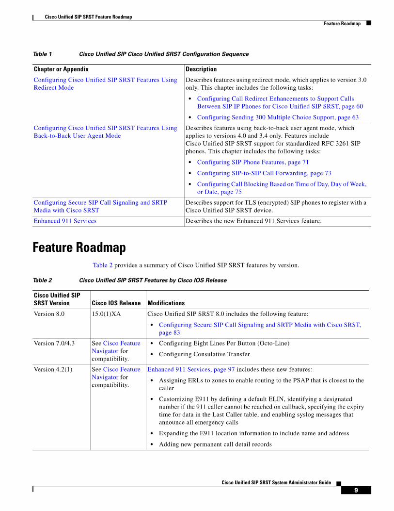
Feature RoadmapTable 2 provides a summary of Cisco Unified SIP SRST features by version.
Configuring Cisco Unified SIP SRST Features Using Redirect Mode
Describes features using redirect mode, which applies to version 3.0 only. This chapter includes the following tasks:
• Configuring Call Redirect Enhancements to Support Calls Between SIP IP Phones for Cisco Unified SIP SRST, page 60
• Configuring Sending 300 Multiple Choice Support, page 63
Configuring Cisco Unified SIP SRST Features Using Back-to-Back User Agent Mode
Describes features using back-to-back user agent mode, which applies to versions 4.0 and 3.4 only. Features include Cisco Unified SIP SRST support for standardized RFC 3261 SIP phones. This chapter includes the following tasks:
• Configuring SIP Phone Features, page 71
• Configuring SIP-to-SIP Call Forwarding, page 73
• Configuring Call Blocking Based on Time of Day, Day of Week, or Date, page 75
Configuring Secure SIP Call Signaling and SRTP Media with Cisco SRST
Describes support for TLS (encrypted) SIP phones to register with a Cisco Unified SIP SRST device.
Enhanced 911 Services Describes the new Enhanced 911 Services feature.
Table 1 Cisco Unified SIP Cisco Unified SRST Configuration Sequence
Chapter or Appendix Description
Table 2 Cisco Unified SIP SRST Features by Cisco IOS Release
Cisco Unified SIP SRST Version Cisco IOS Release Modifications
Version 8.0 15.0(1)XA Cisco Unified SIP SRST 8.0 includes the following feature:
• Configuring Secure SIP Call Signaling and SRTP Media with Cisco SRST, page 83
Version 7.0/4.3 See Cisco Feature Navigator for compatibility.
• Configuring Eight Lines Per Button (Octo-Line)
• Configuring Consulative Transfer
Version 4.2(1) See Cisco Feature Navigator for compatibility.
Enhanced 911 Services, page 97 includes these new features:
• Assigning ERLs to zones to enable routing to the PSAP that is closest to the caller
• Customizing E911 by defining a default ELIN, identifying a designated number if the 911 caller cannot be reached on callback, specifying the expiry time for data in the Last Caller table, and enabling syslog messages that announce all emergency calls
• Expanding the E911 location information to include name and address
• Adding new permanent call detail records
9Cisco Unified SIP SRST System Administrator Guide

Cisco Unified SIP SRST Feature RoadmapFeature Roadmap
Version 4.1 12.4(15)T Cisco Unified SIP SRST 4.1 includes the following features:
• Enabling OOD-R, page 27
• Verifying OOD-R Configuration, page 29
• Troubleshooting OOD-R, page 30
• Enabling KPML for SIP Phones, page 31
• Disabling SIP Supplementary Services for Call Forward and Call Transfer, page 33
• Configuring Idle Prompt Status for SIP Phones, page 34
• Enhanced 911 Services, page 97
Version 4.0 12.4(4)XC —
Version 3.4 12.4(4)T Cisco Unified SIP SRST 3.4 includes the following features:
• Cisco Unified SIP SRST 4.0 and 3.0, page 37
• Configuring Cisco Unified SIP SRST Features Using Redirect Mode, page 59
• Configuring Cisco Unified SIP SRST Features Using Back-to-Back User Agent Mode, page 67
Version 3.2 12.3(11)T The Cisco Unified SIP SRST feature was updated to include additional prerequisite information, including phone and memory requirements.
Version 3.1 12.3(7)T The Cisco Unified SIP SRST feature was integrated into Cisco IOS Release 12.3(7)T.
Version 3.0 12.2(15)ZJ 12.3(4)T
The Cisco Unified SIP SRST feature was introduced.
Table 2 Cisco Unified SIP SRST Features by Cisco IOS Release (continued)
Cisco Unified SIP SRST Version Cisco IOS Release Modifications
10Cisco Unified SIP SRST System Administrator Guide
Cisco Unified SIP SRST Feature Overview
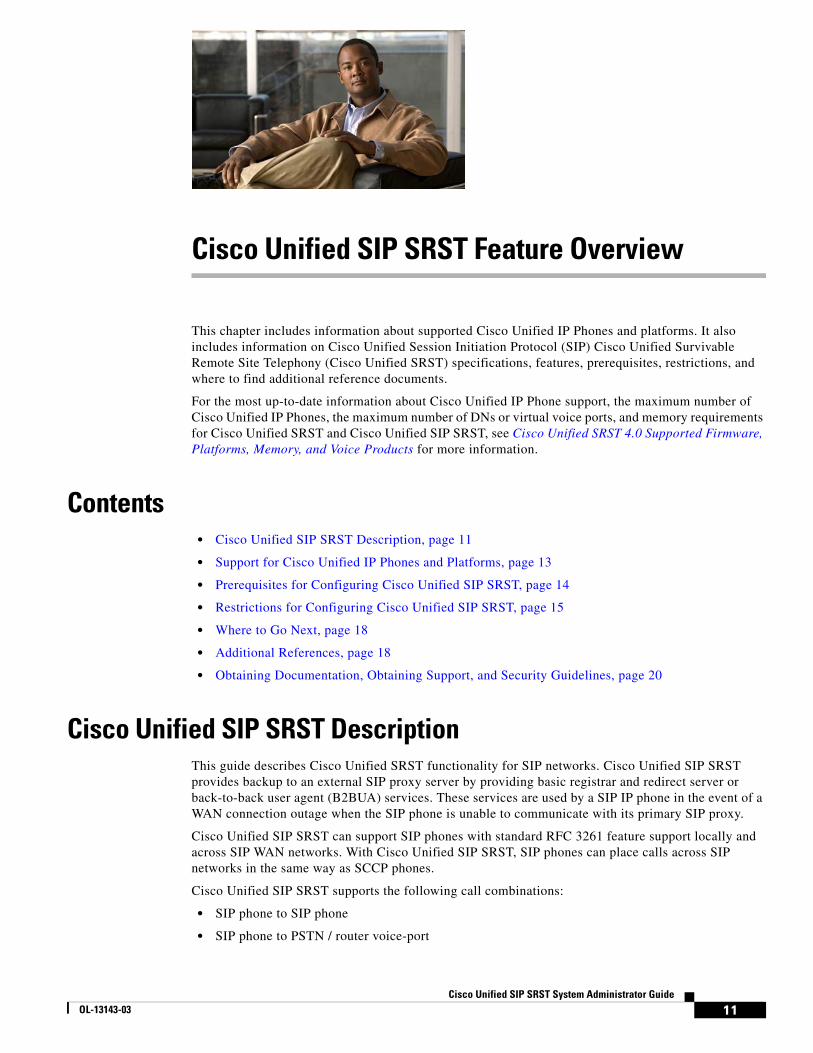
This chapter includes information about supported Cisco Unified IP Phones and platforms. It also includes information on Cisco Unified Session Initiation Protocol (SIP) Cisco Unified Survivable Remote Site Telephony (Cisco Unified SRST) specifications, features, prerequisites, restrictions, and where to find additional reference documents.
For the most up-to-date information about Cisco Unified IP Phone support, the maximum number of Cisco Unified IP Phones, the maximum number of DNs or virtual voice ports, and memory requirements for Cisco Unified SRST and Cisco Unified SIP SRST, see Cisco Unified SRST 4.0 Supported Firmware, Platforms, Memory, and Voice Products for more information.
Contents • Cisco Unified SIP SRST Description, page 11
• Support for Cisco Unified IP Phones and Platforms, page 13
• Prerequisites for Configuring Cisco Unified SIP SRST, page 14
• Restrictions for Configuring Cisco Unified SIP SRST, page 15
• Where to Go Next, page 18
• Additional References, page 18
• Obtaining Documentation, Obtaining Support, and Security Guidelines, page 20
Cisco Unified SIP SRST DescriptionThis guide describes Cisco Unified SRST functionality for SIP networks. Cisco Unified SIP SRST provides backup to an external SIP proxy server by providing basic registrar and redirect server or back-to-back user agent (B2BUA) services. These services are used by a SIP IP phone in the event of a WAN connection outage when the SIP phone is unable to communicate with its primary SIP proxy.
Cisco Unified SIP SRST can support SIP phones with standard RFC 3261 feature support locally and across SIP WAN networks. With Cisco Unified SIP SRST, SIP phones can place calls across SIP networks in the same way as SCCP phones.
Cisco Unified SIP SRST supports the following call combinations:
• SIP phone to SIP phone
• SIP phone to PSTN / router voice-port
11Cisco Unified SIP SRST System Administrator Guide
OL-13143-03

Cisco Unified SIP SRST Feature OverviewCisco Unified SIP SRST Description
• SIP phone to Skinny Client Control Protocol (SCCP) phone
• SIP phone to WAN VoIP using SIP
SIP proxy, registrar, and B2BUA servers are key components of a SIP VoIP network. These servers are usually located in the core of a VoIP network. If SIP phones located at remote sites at the edge of the VoIP network lose connectivity to the network core (because of a WAN outage), they may be unable to make or receive calls. Cisco Unified SIP SRST functionality on a SIP PSTN gateway provides service reliability for SIP-based IP phones in the event of a WAN outage. Cisco Unified SIP SRST enables the SIP IP phones to continue to make and receive calls to and from the PSTN and also to make and receive calls to and from other SIP IP phones.
Figure 1 shows that when the WAN is up, dual registration occurs. The phone registers with the SIP proxy server and the SIP registrar (B2BUA router). But any calls from the SIP phone go to the SIP proxy server through the WAN and out to the PSTN.
Figure 1 Dual Registration when WAN is UP
Figure 2 shows that when the WAN or SIP proxy server goes down, the call from the SIP phone cannot get to the SIP proxy server and instead goes through the B2BUA router out to the PSTN.
IP
IP
1461
32
SIP proxy server
WAN
PSTN
SIP phone
SIP SRST registrar(B2BUA router)
Dual registrationDual registration
12Cisco Unified SIP SRST System Administrator Guide

Cisco Unified SIP SRST Feature OverviewSupport for Cisco Unified IP Phones and Platforms
Figure 2 Call Proceeds with Cisco Unified SIP SRST, When WAN Is Down
Support for Cisco Unified IP Phones and PlatformsThe following sections provide information about Cisco Feature Navigator and the histories of Cisco Unified IP Phone and platform support from Cisco Unified SRST 3.0 to the present version.
• Finding Cisco IOS Software Releases That Support Cisco Unified SRST, page 13
• Cisco Unified IP Phone Support, page 14
• Platform and Memory Support, page 14
Finding Cisco IOS Software Releases That Support Cisco Unified SRST
Note With Cisco IOS Release 12.4(15)T, the number of SIP phones supported on each platform is now equivalent to the number of SCCP phones supported. For example, 3845 now supports 720 phones regardless of whether these are SIP or SCCP.
The tables in this chapter list only the Cisco IOS software releases that first introduce new features to Cisco Unified SRST. Other Cisco IOS software releases may subsequently inherit versions of Cisco Unified SRST. To get a list of Cisco IOS software releases that support a particular version of Cisco Unified SRST, use Cisco Feature Navigator.
Use Cisco Feature Navigator to find information about platform support and Cisco IOS software image support. Access Cisco Feature Navigator at http://www.cisco.com/go/fn. You must have an account on Cisco.com. If you do not have an account or have forgotten your username or password, click Cancel at the login dialog box and follow the instructions that appear.
See the Cisco Unified CME and Cisco IOS Software Version Compatibility Matrix for related compatibility information.
IP
IP
1461
33
SIP proxy server
WAN
PSTN
SIP phone
SIP SRST registrar(B2BUA router)
Dual registrationDual registration
13Cisco Unified SIP SRST System Administrator Guide

Cisco Unified SIP SRST Feature OverviewPrerequisites for Configuring Cisco Unified SIP SRST
Cisco Unified IP Phone SupportCisco Unified IP Phone 7940G and Cisco Unified IP Phone 7960G are fully supported if dual registration is enabled. Dual registration means that the SIP phone is capable of registering with the main SIP proxy and the Cisco Unified SIP SRST device (redirect server or back-to-back user agent) at the same time. If this requirement is not met, the Cisco Unified SIP SRST device may not be capable of routing incoming calls to the SIP phone until the SIP phone registers with the Cisco Unified SIP SRST device.
Cisco Unified IP Phone 7940G and Cisco Unified IP Phone 7960G,l beginning with phone load POS3-04-2-00.bin, are capable of dual registration of the phone’s primary phone line. Additional lines are not registered by the phone for Cisco Unified SIP SRST. To enable dual registration for the primary line, you must set backup proxy information such as proxy_backup and proxy_backup_port in the SIP phone’s configuration file. For configuration instructions, see Cisco Unified IP Phone 7960G/7940G Administrator Guide for SIP, Version 5.0 and 5.1.
Cisco Unified IP Phone 7905G, Cisco Unified IP Phone 7912G, and Cisco Analog Telephone Adaptor (ATA) 186 are not capable of dual registration; thus they are not supported and have limited functionality with Cisco Unified SIP SRST.
Platform and Memory SupportFor the most up-to-date information about Cisco Unified IP Phone support, see Cisco Unified SRST 8.0 Supported Firmware, Platforms, Memory, and Voice Products for more information.
Prerequisites for Configuring Cisco Unified SIP SRSTBefore configuring Cisco Unified SIP SRST, you must do the following:
• An SRST feature license is required to enable the Cisco Unified SIP SRST feature. Contact your account representative if you have further questions. Cisco Unified IP Phone 7940G and Cisco IP Phone 7960G are fully supported if dual registration is enabled. Dual registration means that the SIP phone is capable of registering with the main SIP proxy and the Cisco Unified SIP SRST device (redirect server or back-to-back user agent) at the same time. If this requirement is not met, the Cisco Unified SIP SRST device may not be capable of routing incoming calls to the SIP phone until the SIP phone registers with the Cisco Unified SIP SRST device. Cisco Unified IP Phone 7940G and Cisco Unified IP Phone 7960G, beginning with phone load POS3-04-2-00.bin, are capable of dual registration of the phone’s primary phone line. Additional lines are not registered by the phone for Cisco Unified SIP SRST. To enable dual registration for the primary line, you must set backup proxy information such as proxy_backup and proxy_backup_port in the SIP phone’s configuration file. For configuration instructions, see Cisco Unified IP Phone 7960G/7940G Administrator Guide for SIP, Version 5.0 and 5.1.
• When the WAN goes down, for each outgoing call the SIP phone continues to send the SIP proxy server up to seven Invite messages. If the Invite messages are not acknowledged, the SIP phone switches to Cisco Unified SIP SRST to route the call. Thus, there may be a few seconds delay before Cisco Unified SIP SRST takes over call processing from the SIP proxy server. If your network is designed to return an ICMP host unreachable indication to the phone in response to an outgoing SIP Invite message when the WAN is down, the phone responds by switching to the Cisco Unified SIP SRST router more rapidly.
14Cisco Unified SIP SRST System Administrator Guide

Cisco Unified SIP SRST Feature OverviewRestrictions for Configuring Cisco Unified SIP SRST
Dual registration is not supported on the Cisco Unified IP Phone 7905G, Cisco Unified IP Phone 7912G, or Cisco Analog Telephone Adaptor (ATA) series with a SIP image. Therefore auto registration to the Cisco Unified SIP SRST Router is not available.
• If the WAN is down, and you reboot your Cisco Unified SIP SRST router, when the router reloads it will have no database of SIP phone registrations. The SIP phones will have to register again, which could take several minutes, because SIP phones do not use a keepalive functionality. To shorten the time before the phones re-register, the registration expiry can be adjusted with the registrar server command. The default expiry is 3600 seconds; an expiry of 600 seconds is recommended.
• For the prerequisites for the new feature introduced in Version 4.1, Enhanced 911 Services for Cisco Unified SRST, see the “Prerequisites” section on page 97.
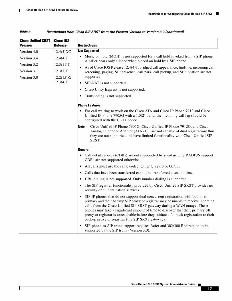
Restrictions for Configuring Cisco Unified SIP SRSTTable 3 provides the restrictions of Cisco the present version.
Table 3 Restrictions from Cisco SIP SRST from the Present Version to Version 3.0
Cisco Unified SRST Version
Cisco IOS Release Restrictions
Version 8.0 15.0(1)XA • SIP phones may be configured on the Cisco Unified Communications Manager (CM) with an Authenticated device security mode. The Cisco Unified CM ensures integrity and authentication for the phone using a TLS connection with NULL-SHA cipher for signaling. If such an Authenticated SIP phone fails over to the Cisco Unified SRST device, and if the Cisco Unified Communications Manager and SRST device are configured to support secure SIP SRST, it will register using TCP instead of TLS/TCP, thus disabling the Authenticated mode until the phone fails back to the Cisco Unified Communications Manager.
15Cisco Unified SIP SRST System Administrator Guide

Cisco Unified SIP SRST Feature OverviewRestrictions for Configuring Cisco Unified SIP SRST
Version 4.1 12.4.(15)T • Cisco Unified SRST does not support BLF speed-dial notification, call forward all synchronization, dial plans, directory services, or music-on-hold (MOH).
• Prior to SIP phone load 8.0, SIP phones maintained dual registration with both Cisco Unified Communications Manager and Cisco Unified SRST simultaneously. In SIP phone load 8.0 and later versions, SIP phones use keepalive to maintain a connection with Cisco Unified SRST during active registration with Cisco Unified Communications Manager. Every two minutes, a SIP phone sends a keepalive message to Cisco Unified SRST. Cisco Unified SRST responds to this keepalive with a 404 message. This process repeats until fallback to Cisco Unified SRST occurs. After fallback, SIP phones send a keepalive message every two minutes to Cisco Unified Communications Manager while the phones are registered with Cisco Unified SRST. Cisco Unified SRST continues to support dual registration for SIP phone loads older than 8.0.
• Enhanced 911 Services for Cisco Unified SRST does not interface with the Cisco Emergency Responder.
• The information about the most recent phone that called 911 is not preserved after a reboot of Cisco Unified SRST.
• Cisco Emergency Responder does not have access to any updates made to the emergency call history table when remote IP Phones are in Cisco Unified SRST fallback mode. Therefore, if the PSAP calls back after the Cisco Unified IP Phones register back to Cisco Unified Communications Manager, Cisco Emergency Responder will not have any history of those calls. As a result, those calls will not get routed to the original 911 caller. Instead, the calls are routed to the default destination that is configured on Cisco Emergency Responder for the corresponding ELIN.
• For Cisco Unified Wireless 7920 and 7921 IP Phones, a caller’s location can only be determined by the static information configured by the system administrator. For more information, see the “Precautions for Mobile Phones” section on page 103.
• The extension numbers of 911 callers can be translated to only two emergency location identification numbers (ELINs) for each emergency response location (ERL). For more information, see the “Overview” section on page 98.
• Using ELINs for multiple purposes can result in unexpected interactions with existing Cisco Unified SRST features. These multiple uses of an ELIN can include configuring an ELIN for use as an actual phone number (ephone-dn, voice register dn, or FXS destination-pattern), a Call Pickup number, or an alias rerouting number. For more information, see the “Multiple Usages of an ELIN” section on page 106.
• There are a number of other ways that your configuration of Enhanced 911 Services can interact with existing Cisco Unified SRST features and cause unexpected behavior. For a complete description of interactions between Enhanced 911 Services and existing Cisco Unified SRST features, see the “Interactions with Existing Cisco Unified SIP SRST Features” section on page 106.
Table 3 Restrictions from Cisco SIP SRST from the Present Version to Version 3.0 (continued)
Cisco Unified SRST Version
Cisco IOS Release Restrictions
16Cisco Unified SIP SRST System Administrator Guide
Cisco Unified SIP SRST Feature OverviewRestrictions for Configuring Cisco Unified SIP SRST
Version 4.0
Version 3.4
Version 3.2
Version 3.1
Version 3.0
12.4(4)XC
12.4(4)T
12.3(11)T
12.3(7)T
12.2(15)ZJ 12.3(4)T
Not Supported
• Music on hold (MOH) is not supported for a call hold invoked from a SIP phone. A caller hears only silence when placed on hold by a SIP phone.
• As of Cisco IOS Release 12.4(4)T, bridged call appearance, find-me, incoming call screening, paging, SIP presence, call park, call pickup, and SIP location are not supported.
• SIP-NAT is not supported.
• Cisco Unity Express is not supported.
• Transcoding is not supported.
Phone Features
• For call waiting to work on the Cisco ATA and Cisco IP Phone 7912 and Cisco Unified IP Phone 7905G with a 1.0(2) build, the incoming call leg should be configured with the G.711 codec.
Note Cisco Unified IP Phone 7905G, Cisco Unified IP Phone 7912G, and Cisco Analog Telephone Adaptor (ATA) 186 are not capable of dual registration; thus they are not supported and have limited functionality with Cisco Unified SIP SRST.
General
• Call detail records (CDRs) are only supported by standard IOS RADIUS support; CDRs are not supported otherwise.
• All calls must use the same codec, either G.729r8 or G.711.
• Calls that have been transferred cannot be transferred a second time.
• URL dialing is not supported. Only number dialing is supported.
• The SIP registrar functionality provided by Cisco Unified SIP SRST provides no security or authentication services.
• SIP IP phones that do not support dual concurrent registration with both their primary and their backup SIP proxy or registrar may be unable to receive incoming calls from the Cisco Unified SIP SRST gateway during a WAN outage. These phones may take a significant amount of time to discover that their primary SIP proxy or registrar is unreachable before they initiate a fallback registration to their backup proxy or registrar (the SIP SRST gateway).
• SIP-phone-to-SIP-trunk support requires Refer and 302/300 Redirection to be supported by the SIP trunk (Version 3.0).
Table 3 Restrictions from Cisco SIP SRST from the Present Version to Version 3.0 (continued)
Cisco Unified SRST Version
Cisco IOS Release Restrictions
17Cisco Unified SIP SRST System Administrator Guide

Cisco Unified SIP SRST Feature OverviewWhere to Go Next
Where to Go NextThe next chapters of this book describe how to configure Cisco Unified SIP SRST. As shown in Table 4, each chapter takes you through tasks in the order in which they need to be performed. The first task for configuring Cisco Unified SRST is to ensure that the basic software and hardware in your system are configured correctly for Cisco Unified SRST. For instructions, see the “Prerequisites for Configuring Cisco Unified SIP SRST” section on page 14.
Additional ReferencesThe following sections provide additional references related to Cisco Unified SIP SRST:
• Related Documents, page 19
• Standards, page 19
• MIBs, page 19
• RFCs, page 19
• Technical Assistance, page 20
Table 4 Cisco Unified SRST Configuration Sequence
Task Where Task Is Described
1. Configuring Version 4.1 features “Cisco Unified SIP SRST 4.1” chapter
2. Upgrading to Version 4.0 from 3.0 “Cisco Unified SIP SRST 4.0 and 3.0” chapter
3. Providing a backup to an external SIP proxy server by supplying basic registrar services
“Configuring the SIP Registrar” chapter
4. Understanding basic Cisco Unified SIP SRST and local SIP phone configurations introduced in Version 3.0
“Configuring Cisco Unified SIP SRST Features Using Redirect Mode” chapter
5. Understanding global phone configurations and features such as call forwarding that were introduced in Version 3.0
“Configuring Cisco Unified SIP SRST Features Using Back-to-Back User Agent Mode” chapter
6. Configuring Secure SIP Call Signaling and SRTP Media
“Configuring Secure SIP Call Signaling and SRTP Media with Cisco SRST” chapter
7. Configuring non-secure TCP Call Signaling
“Configuring Secure SIP Call Signaling and SRTP Media with Cisco SRST” chapter
8. Configuring Enhanced 911 Services “Enhanced 911 Services” chapter
18Cisco Unified SIP SRST System Administrator Guide

Cisco Unified SIP SRST Feature OverviewAdditional References
Related Documents
Standards
MIBs
RFCs
Related Topic Documents
Cisco IOS voice product configuration. • Cisco IOS Voice Configuration Library
Cisco Unified SRST commands and specifications • Cisco Unified SRST and Cisco Unified SIP SRST Command Reference (All Versions)
• Cisco Unified SRST 8.0 Supported Firmware, Platforms, Memory, and Voice Products
Cisco Unified SRST System Administrator Guide • Cisco Unified SRST System Administrator Guide
Cisco Unified IP Phones • Cisco Unified IP Phones 7900 Series
Cisco SIP SRST V3.4: Cisco IOS SIP Survivable Remote Site Telephony Feature Roadmap
• Cisco IOS SIP SRST Feature Roadmap
Cisco SIP functionality • Cisco IOS SIP Configuration Guide
Command reference information for voice and telephony commands
• Cisco IOS Voice Command Reference
• Cisco IOS Debug Command Reference
Standard preface • Cisco IOS Voice Configuration Library Preface
Standard glossary • Cisco IOS Voice Configuration Library Glossary
Standard Title
No new or modified standards are supported by this feature, and support for existing standards has not been modified by this feature.
—
MIB MIBs Link
No new or modified MIBs are supported by this feature, and support for existing MIBs has not been modified by this feature.
To locate and download MIBs for selected platforms, Cisco IOS releases, and feature sets, use Cisco MIB Locator found at the following URL:
http://www.cisco.com/go/mibs
RFC Title
RFC 2543 SIP: Session Initiation Protocol
RFC 3261 SIP: Session Initiation Protocol
19Cisco Unified SIP SRST System Administrator Guide
Cisco Unified SIP SRST Feature OverviewObtaining Documentation, Obtaining Support, and Security Guidelines
Technical Assistance
Obtaining Documentation, Obtaining Support, and Security Guidelines
For information on obtaining documentation, obtaining support, providing documentation feedback, security guidelines, and also recommended aliases and general Cisco documents, see the monthly What’s New in Cisco Product Documentation, which also lists all new and revised Cisco technical documentation, at:
http://www.cisco.com/en/US/docs/general/whatsnew/whatsnew.html
Description Link
The Cisco Technical Support & Documentation website contains thousands of pages of searchable technical content, including links to products, technologies, solutions, technical tips, and tools. Registered Cisco.com users can log in from this page to access even more content.
http://www.cisco.com/techsupport
20Cisco Unified SIP SRST System Administrator Guide

Cisco Unified SIP SRST 4.1
This chapter describes the features and provides the configuration information for Cisco Unified SIP SRST 4.1:
• Out-of-Dialog REFER(OOD-R)
• Presence Service
• Digit Collection on SIP Phones
• Caller ID Display
• Disabling SIP Supplementary Services for Call Forward and Call Transfer
• Idle Prompt Status
Note With Cisco IOS Release 12.4(15)T, the number of SIP phones supported on each platform is now equivalent to the number of SCCP phones supported. For example, 3845 now supports 720 phones regardless of whether these are SIP or SCCP.
Contents • Prerequisites for Cisco Unified SIP SRST 4.1, page 21
• Restrictions for Cisco Unified SIP SRST 4.1, page 22
• Information About Cisco Unified SIP SRST 4.1, page 22
• How to Configure Cisco Unified SIP SRST 4.1 Features, page 27
• Where to Go Next, page 35
Prerequisites for Cisco Unified SIP SRST 4.1 • Cisco IOS Release 12.4(15)T or a later release.
• Cisco Unified IP Phones 7911G, 7941G, 7941GE, 7961G, 7961GE, 7970G, and 7971GE require firmware load 8.2(1) or a later version.
• For the prerequisites for the Enhanced 911 Services for Cisco Unified SRST feature, introduced in Version 4.1, see the “Prerequisites” section on page 97.
21Cisco Unified SIP SRST System Administrator Guide
OL-13143-03

Cisco Unified SIP SRST 4.1Restrictions for Cisco Unified SIP SRST 4.1
Restrictions for Cisco Unified SIP SRST 4.1 • Cisco Unified SRST does not support BLF speed-dial notification, call forward all synchronization,
dial plans, directory services, or music on hold (MOH).
• Prior to SIP phone load 8.0, SIP phones maintained dual registration with both Cisco Unified Communications Manager and Cisco Unified SRST simultaneously. In SIP phone load 8.0 and later versions, SIP phones use keepalive to maintain a connection with Cisco Unified SRST during active registration with Cisco Unified Communications Manager. Every two minutes, a SIP phone sends a keepalive message to Cisco Unified SRST. Cisco Unified SRST responds to this keepalive with a 404 message. This process repeats until fallback to Cisco Unified SRST occurs. After fallback, SIP phones send a keepalive message every two minutes to Cisco Unified Communications Manager while the phones are registered with Cisco Unified SRST. Cisco Unified SRST continues to support dual registration for SIP phone loads older than 8.0.
Information About Cisco Unified SIP SRST 4.1 • Out-of-Dialog REFER, page 22
• Presence Service, page 23
• Disabling SIP Supplementary Services for Call Forward and Call Transfer, page 26
• Caller ID Display, page 26
• Disabling SIP Supplementary Services for Call Forward and Call Transfer, page 26
• Idle Prompt Status, page 26
• Enhanced 911 Services, page 27
Out-of-Dialog REFEROut-of-dialog REFER (OOD-R) enables remote applications to establish calls by sending a REFER message to Cisco Unified SRST without an initial INVITE. After the REFER is sent, the remainder of the call setup is independent of the application and the media stream does not flow through the application. The application using OOD-R triggers a call setup request that specifies the Referee address in the Request-URI and the Refer-Target in the Refer-To header. The SIP messaging used to communicate with Cisco Unified SRST is independent of the end-user device protocol, which can be H.323, POTS, SCCP, or SIP. Click-to-dial is an example of an application that can be created using OOD-R.
A click-to-dial application enables users to combine multiple steps into one click for a call setup. For example, a user can click a web-based directory application from his or her PC to look up a telephone number, off-hook the desktop phone, and dial the called number. The application initiates the call setup without the user having to out-dial from his or her own phone. The directory application sends a REFER message to Cisco Unified SRST, which sets up the call between both parties based on this REFER.
Figure 3 shows an example of OOD-R being used by a click-to-dial application. In this scenario, the following events occur (refer to the event numbers in the illustration):
1. Remote user clicks to dial.
2. Application sends out-of-dialog REFER to Cisco Unified SRST.
22Cisco Unified SIP SRST System Administrator Guide

Cisco Unified SIP SRST 4.1Information About Cisco Unified SIP SRST 4.1
3. Cisco Unified SRST 1 connects to SIP phone 1 (Referee).
4. Cisco Unified SRST 1 sends INVITE to SRST 2.
5. Cisco Unified SRST 2 sends INVITE to SIP phone 2 (Refer-Target) and the call is accepted.
6. Voice path is created between the two SIP phones.
Note The connectivity to Cisco Unified Communications Manager has been lost and, therefore, IP phone 1 and IP phone 2 have registered to Cisco Unified SRST routers.
Figure 3 Click-to-Dial Application using Out-of-Dialog REFER
The initial OOD-R request can be authenticated and authorized using RFC 2617-based digest authentication. To support authentication, Cisco Unified SRST retrieves the credential information from a text file stored in flash. This mechanism is used by Cisco Unified SRST in addition to phone-based credentials. The same credential file can be shared by other services that require request-based authentication and authorization such as presence service. Up to five credential files can be configured and loaded into the system. The contents of these five files are mutually exclusive, meaning that the username and password pairs must be unique across all the files. The username and password pairs must also be different than those configured for SCCP or SIP phones in a Cisco Unified SRST system.
For configuration information, see the “Enabling OOD-R” section on page 27.
Presence ServiceA presence service, as defined in RFC 2778 and RFC 2779, is a system for finding, retrieving, and distributing presence information from a source, called a presence entity (presentity), to an interested party called a watcher. When you configure presence in a Cisco Unified SRST system with a SIP WAN connection, a phone user, or a watcher, can monitor the real-time status of another user at a directory number, the presentity. Presence enables the calling party to know before dialing whether the called party is available. For example, a directory application might show that a user is busy, saving the caller the time and inconvenience of not being able to reach the party.
2310
69
IP IP
IP
PSTN
CCM
SRST
SRSTDirectoryservices
application
SIP(Connectivity to
CCM lost)
IP phone 2IP phone 16
3
2
6
4
6 51
23Cisco Unified SIP SRST System Administrator Guide

Cisco Unified SIP SRST 4.1Information About Cisco Unified SIP SRST 4.1
Presence uses the SIP SUBSCRIBE and NOTIFY methods to enable users and applications to subscribe to changes in the line status of phones in a Cisco Unified SRST system. Phones act as watchers and a presentity is identified by a directory number on a phone. Watchers initiate presence requests (SUBSCRIBE messages) to obtain the line status of a presentity. The Cisco Unified SRST system responds with the presentity’s status. Each time a status changes for a presentity, all watchers of this presentity are sent a notification message. SIP phones and trunks use SIP messages; SCCP phones use presence primitives in SCCP messages.
Presence supports Busy Lamp Field (BLF) notification features for speed-dial buttons and directory call lists for missed calls, placed calls, and received calls. SIP and SCCP phones that support the BLF speed-dial and the BLF call-list features can subscribe to status change notification for internal and external directory numbers.
Figure 4 shows a Cisco Unified CME system supporting BLF notification for internal and external directory numbers. If the watcher and the presentity are not both internal to the Cisco Unified CME or Cisco Unified SRST router, the subscribe message is handled by a presence proxy server.
Figure 4 BLF Notification Using Presence
The following line states display through BLF indicators on the phone:
• Line is idle: Displays when this line is not being used.
• Line is in-use: Displays when the line is in the ringing state and when a user is on the line, whether or not this line can accept a new call.
• BLF indicator unknown: Phone is unregistered or this line is not allowed to be watched.
Cisco Unified SRST acts as a presence agent for internal lines (both SIP and SCCP) and as presence servers for external watchers connected through a SIP trunk, providing the following functionality:
• Processes SUBSCRIBE requests from internal lines to internal lines. Notifies internal subscribers of any status change.
• Processes incoming SUBSCRIBE requests from a SIP trunk for internal SCCP and SIP lines. Notifies external subscribers of any status change.
• Sends SUBSCRIBE requests to external presentities on behalf of internal lines. Relays status responses to internal lines.
1557
90IPIP
PSTN
SubscribeNotify
SIP
V
IPIP
IPIP
IPIP
Cisco Unified CMECisco Unified CME
SubscribeNotify
24Cisco Unified SIP SRST System Administrator Guide
Cisco Unified SIP SRST 4.1Information About Cisco Unified SIP SRST 4.1
Presence subscription requests from SIP trunks can be authenticated and authorized. Local subscription requests cannot be authenticated.
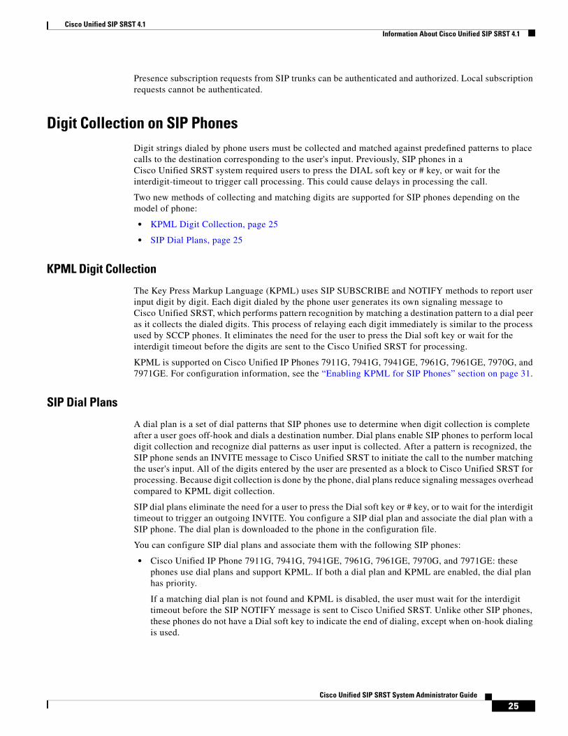
Digit Collection on SIP PhonesDigit strings dialed by phone users must be collected and matched against predefined patterns to place calls to the destination corresponding to the user's input. Previously, SIP phones in a Cisco Unified SRST system required users to press the DIAL soft key or # key, or wait for the interdigit-timeout to trigger call processing. This could cause delays in processing the call.
Two new methods of collecting and matching digits are supported for SIP phones depending on the model of phone:
• KPML Digit Collection, page 25
• SIP Dial Plans, page 25
KPML Digit Collection
The Key Press Markup Language (KPML) uses SIP SUBSCRIBE and NOTIFY methods to report user input digit by digit. Each digit dialed by the phone user generates its own signaling message to Cisco Unified SRST, which performs pattern recognition by matching a destination pattern to a dial peer as it collects the dialed digits. This process of relaying each digit immediately is similar to the process used by SCCP phones. It eliminates the need for the user to press the Dial soft key or wait for the interdigit timeout before the digits are sent to the Cisco Unified SRST for processing.
KPML is supported on Cisco Unified IP Phones 7911G, 7941G, 7941GE, 7961G, 7961GE, 7970G, and 7971GE. For configuration information, see the “Enabling KPML for SIP Phones” section on page 31.
SIP Dial Plans
A dial plan is a set of dial patterns that SIP phones use to determine when digit collection is complete after a user goes off-hook and dials a destination number. Dial plans enable SIP phones to perform local digit collection and recognize dial patterns as user input is collected. After a pattern is recognized, the SIP phone sends an INVITE message to Cisco Unified SRST to initiate the call to the number matching the user's input. All of the digits entered by the user are presented as a block to Cisco Unified SRST for processing. Because digit collection is done by the phone, dial plans reduce signaling messages overhead compared to KPML digit collection.
SIP dial plans eliminate the need for a user to press the Dial soft key or # key, or to wait for the interdigit timeout to trigger an outgoing INVITE. You configure a SIP dial plan and associate the dial plan with a SIP phone. The dial plan is downloaded to the phone in the configuration file.
You can configure SIP dial plans and associate them with the following SIP phones:
• Cisco Unified IP Phone 7911G, 7941G, 7941GE, 7961G, 7961GE, 7970G, and 7971GE: these phones use dial plans and support KPML. If both a dial plan and KPML are enabled, the dial plan has priority.
If a matching dial plan is not found and KPML is disabled, the user must wait for the interdigit timeout before the SIP NOTIFY message is sent to Cisco Unified SRST. Unlike other SIP phones, these phones do not have a Dial soft key to indicate the end of dialing, except when on-hook dialing is used.
25Cisco Unified SIP SRST System Administrator Guide
Cisco Unified SIP SRST 4.1Information About Cisco Unified SIP SRST 4.1
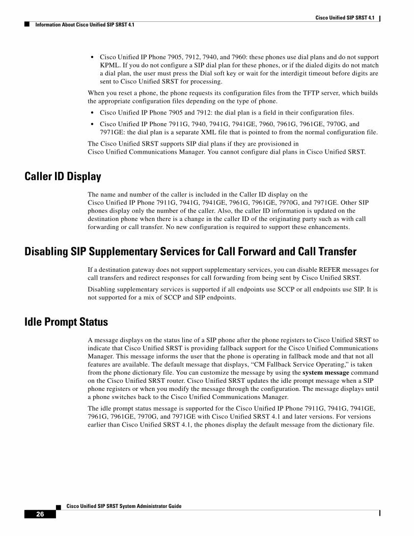
• Cisco Unified IP Phone 7905, 7912, 7940, and 7960: these phones use dial plans and do not support KPML. If you do not configure a SIP dial plan for these phones, or if the dialed digits do not match a dial plan, the user must press the Dial soft key or wait for the interdigit timeout before digits are sent to Cisco Unified SRST for processing.
When you reset a phone, the phone requests its configuration files from the TFTP server, which builds the appropriate configuration files depending on the type of phone.
• Cisco Unified IP Phone 7905 and 7912: the dial plan is a field in their configuration files.
• Cisco Unified IP Phone 7911G, 7940, 7941G, 7941GE, 7960, 7961G, 7961GE, 7970G, and 7971GE: the dial plan is a separate XML file that is pointed to from the normal configuration file.
The Cisco Unified SRST supports SIP dial plans if they are provisioned in Cisco Unified Communications Manager. You cannot configure dial plans in Cisco Unified SRST.
Caller ID DisplayThe name and number of the caller is included in the Caller ID display on the Cisco Unified IP Phone 7911G, 7941G, 7941GE, 7961G, 7961GE, 7970G, and 7971GE. Other SIP phones display only the number of the caller. Also, the caller ID information is updated on the destination phone when there is a change in the caller ID of the originating party such as with call forwarding or call transfer. No new configuration is required to support these enhancements.
Disabling SIP Supplementary Services for Call Forward and Call TransferIf a destination gateway does not support supplementary services, you can disable REFER messages for call transfers and redirect responses for call forwarding from being sent by Cisco Unified SRST.
Disabling supplementary services is supported if all endpoints use SCCP or all endpoints use SIP. It is not supported for a mix of SCCP and SIP endpoints.
Idle Prompt StatusA message displays on the status line of a SIP phone after the phone registers to Cisco Unified SRST to indicate that Cisco Unified SRST is providing fallback support for the Cisco Unified Communications Manager. This message informs the user that the phone is operating in fallback mode and that not all features are available. The default message that displays, “CM Fallback Service Operating,” is taken from the phone dictionary file. You can customize the message by using the system message command on the Cisco Unified SRST router. Cisco Unified SRST updates the idle prompt message when a SIP phone registers or when you modify the message through the configuration. The message displays until a phone switches back to the Cisco Unified Communications Manager.
The idle prompt status message is supported for the Cisco Unified IP Phone 7911G, 7941G, 7941GE, 7961G, 7961GE, 7970G, and 7971GE with Cisco Unified SRST 4.1 and later versions. For versions earlier than Cisco Unified SRST 4.1, the phones display the default message from the dictionary file.
26Cisco Unified SIP SRST System Administrator Guide

Cisco Unified SIP SRST 4.1How to Configure Cisco Unified SIP SRST 4.1 Features
Enhanced 911 ServicesEnhanced 911 Services for Cisco Unified SRST enables 911 operators to:
• Immediately pinpoint the location of the 911 caller based on the calling number
• Callback the 911 caller if a disconnect occurs
Before this feature was introduced, Cisco Unified SRST supported only outbound calls to 911. With basic 911 functionality, calls were simply routed to a public safety answering point (PSAP). The 911 operator at the PSAP would then have to verbally gather the emergency information and location from the caller, before dispatching a response team from the ambulance service, fire department, or police department. Calls could not be routed to different PSAPs, based on the specific geographic areas that they cover.
With Enhanced 911 Services, 911 calls are selectively routed to the closest PSAP based on the caller’s location. In addition, the caller’s phone number and address automatically display on a terminal at the PSAP. Therefore, the PSAP can quickly dispatch emergency help, even if the caller is unable to communicate the location. Also, if the caller disconnects prematurely, the PSAP has the information it needs to contact the 911 caller.
For more information about Enhanced 911 Services, see the “Enhanced 911 Services” section on page 97
How to Configure Cisco Unified SIP SRST 4.1 FeaturesThis section contains the following tasks:
• Enabling OOD-R, page 27
• Verifying OOD-R Configuration, page 29
• Troubleshooting OOD-R, page 30
• Enabling KPML for SIP Phones, page 31
• Disabling SIP Supplementary Services for Call Forward and Call Transfer, page 33
• Configuring Idle Prompt Status for SIP Phones, page 34
• Configuring Enhanced 911 Services, page 35
Enabling OOD-RPerform the following steps to enable OOD-R support on the Cisco Unified SRST router.
Prerequisites
The application that initiates OOD-R, such as a click-to-dial application, and its directory server must be installed and configured.
Restrictions
• The call waiting, conferencing, hold, and transfer call features are not supported while the Refer-Target is ringing.
• In a SIP-to-SIP scenario, no ringback is heard by the Referee when Refer-Target is ringing.
27Cisco Unified SIP SRST System Administrator Guide

Cisco Unified SIP SRST 4.1How to Configure Cisco Unified SIP SRST 4.1 Features
SUMMARY STEPS
1. enable
2. configure terminal
3. sip-ua
4. refer-ood enable [request-limit]
5. exit
6. voice register global
7. authenticate ood-refer
8. authenticate credential tag location
9. end
DETAILED STEPS
Command or Action Purpose
Step 1 enable
Example:Router> enable
Enables privileged EXEC mode.
• Enter your password if prompted.
Step 2 configure terminal
Example:Router# configure terminal
Enters global configuration mode.
Step 3 sip-ua
Example:Router(config)# sip-ua
Enters SIP user-agent configuration mode to configure the user agent.
Step 4 refer-ood enable [request-limit]
Example:Router(config-sip-ua)# refer-ood enable 300
Enables OOD-R processing.
• request-limit: Maximum number of concurrent incoming OOD-R requests that the router can process. Range: 1 to 500. Default: 500.
Step 5 exit
Example:Router(config-sip-ua)# exit
Exits SIP user-agent configuration mode.
Step 6 voice register global
Example:Router(config)# voice register global
Enters voice register global configuration mode to set global parameters for all supported SIP phones in a Cisco Unified SRST environment.
Step 7 authenticate ood-refer
Example:Router(config-register-global)# authenticate ood-refer
(Optional) Enables authentication of incoming OOD-R requests using RFC 2617-based digest authentication.
28Cisco Unified SIP SRST System Administrator Guide
Cisco Unified SIP SRST 4.1How to Configure Cisco Unified SIP SRST 4.1 Features
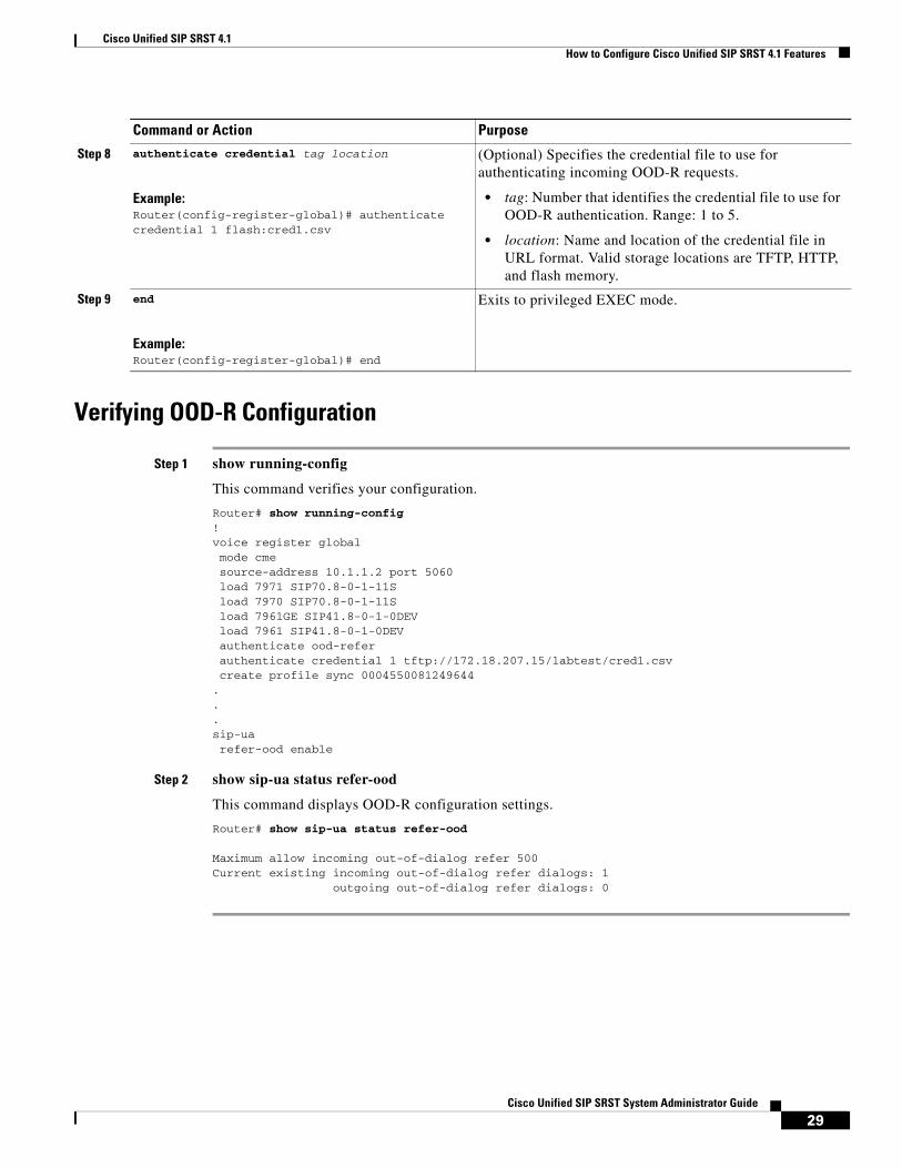
Verifying OOD-R Configuration
Step 1 show running-config
This command verifies your configuration.
Router# show running-config!voice register global mode cme source-address 10.1.1.2 port 5060 load 7971 SIP70.8-0-1-11S load 7970 SIP70.8-0-1-11S load 7961GE SIP41.8-0-1-0DEV load 7961 SIP41.8-0-1-0DEV authenticate ood-refer authenticate credential 1 tftp://172.18.207.15/labtest/cred1.csv create profile sync 0004550081249644...sip-ua refer-ood enable
Step 2 show sip-ua status refer-ood
This command displays OOD-R configuration settings.
Router# show sip-ua status refer-ood Maximum allow incoming out-of-dialog refer 500Current existing incoming out-of-dialog refer dialogs: 1 outgoing out-of-dialog refer dialogs: 0
Step 8 authenticate credential tag location
Example:Router(config-register-global)# authenticate credential 1 flash:cred1.csv
(Optional) Specifies the credential file to use for authenticating incoming OOD-R requests.
• tag: Number that identifies the credential file to use for OOD-R authentication. Range: 1 to 5.
• location: Name and location of the credential file in URL format. Valid storage locations are TFTP, HTTP, and flash memory.
Step 9 end
Example:Router(config-register-global)# end
Exits to privileged EXEC mode.
Command or Action Purpose
29Cisco Unified SIP SRST System Administrator Guide
Cisco Unified SIP SRST 4.1How to Configure Cisco Unified SIP SRST 4.1 Features
Troubleshooting OOD-R
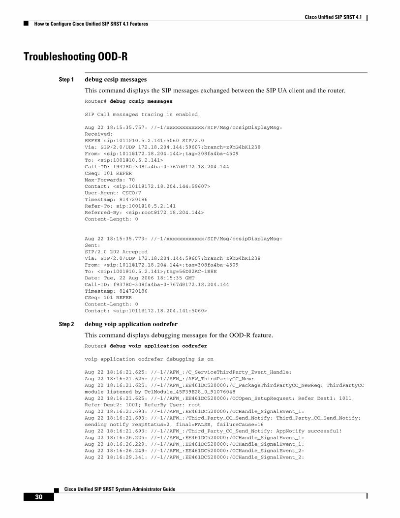
Step 1 debug ccsip messages
This command displays the SIP messages exchanged between the SIP UA client and the router.
Router# debug ccsip messages SIP Call messages tracing is enabled Aug 22 18:15:35.757: //-1/xxxxxxxxxxxx/SIP/Msg/ccsipDisplayMsg:Received: REFER sip:[email protected]:5060 SIP/2.0Via: SIP/2.0/UDP 172.18.204.144:59607;branch=z9hG4bK1238From: <sip:[email protected]>;tag=308fa4ba-4509To: <sip:[email protected]>Call-ID: [email protected]: 101 REFERMax-Forwards: 70Contact: <sip:[email protected]:59607>User-Agent: CSCO/7Timestamp: 814720186Refer-To: sip:[email protected]: <sip:[email protected]>Content-Length: 0 Aug 22 18:15:35.773: //-1/xxxxxxxxxxxx/SIP/Msg/ccsipDisplayMsg:Sent: SIP/2.0 202 AcceptedVia: SIP/2.0/UDP 172.18.204.144:59607;branch=z9hG4bK1238From: <sip:[email protected]>;tag=308fa4ba-4509To: <sip:[email protected]>;tag=56D02AC-1E8EDate: Tue, 22 Aug 2006 18:15:35 GMTCall-ID: [email protected]: 814720186CSeq: 101 REFERContent-Length: 0Contact: <sip:[email protected]:5060>
Step 2 debug voip application oodrefer
This command displays debugging messages for the OOD-R feature.
Router# debug voip application oodrefer voip application oodrefer debugging is on Aug 22 18:16:21.625: //-1//AFW_:/C_ServiceThirdParty_Event_Handle: Aug 22 18:16:21.625: //-1//AFW_:/AFW_ThirdPartyCC_New: Aug 22 18:16:21.625: //-1//AFW_:EE461DC520000:/C_PackageThirdPartyCC_NewReq: ThirdPartyCC module listened by TclModule_45F39E28_0_91076048Aug 22 18:16:21.625: //-1//AFW_:EE461DC520000:/OCOpen_SetupRequest: Refer Dest1: 1011, Refer Dest2: 1001; ReferBy User: rootAug 22 18:16:21.693: //-1//AFW_:EE461DC520000:/OCHandle_SignalEvent_1: Aug 22 18:16:21.693: //-1//AFW_:/Third_Party_CC_Send_Notify: Third_Party_CC_Send_Notify: sending notify respStatus=2, final=FALSE, failureCause=16Aug 22 18:16:21.693: //-1//AFW_:/Third_Party_CC_Send_Notify: AppNotify successful!Aug 22 18:16:26.225: //-1//AFW_:EE461DC520000:/OCHandle_SignalEvent_1: Aug 22 18:16:26.229: //-1//AFW_:EE461DC520000:/OCHandle_SignalEvent_1: Aug 22 18:16:26.249: //-1//AFW_:EE461DC520000:/OCHandle_SignalEvent_2: Aug 22 18:16:29.341: //-1//AFW_:EE461DC520000:/OCHandle_SignalEvent_2:
30Cisco Unified SIP SRST System Administrator Guide

Cisco Unified SIP SRST 4.1How to Configure Cisco Unified SIP SRST 4.1 Features
Aug 22 18:16:29.341: //-1//AFW_:/Third_Party_CC_Send_Notify: Third_Party_CC_Send_Notify: sending notify respStatus=4, final=TRUE, failureCause=16Aug 22 18:16:29.341: //-1//AFW_:/Third_Party_CC_Send_Notify: AppNotify successful!Aug 22 18:16:29.349: //-1//AFW_:EE461DC520000:/OCHandle_Handoff: BAG contains: Aug 22 18:16:29.349: LEG[895 ][LEG_INCCONNECTED(5)][Cause(0)]Aug 22 18:16:29.349: CON[7 ][CONNECTION_CONFED(2)] {LEG[895 ][LEG_INCCONNECTED(5)][Cause(0)],LEG[896 ][LEG_OUTCONNECTED(10)][Cause(0)]}Aug 22 18:16:29.349: LEG[896 ][LEG_OUTCONNECTED(10)][Cause(0)]Aug 22 18:16:29.365: //-1//AFW_:EE461DC520000:/OCAnyState_IgnoreEvent: Event IgnoredAug 22 18:16:29.365: //-1//AFW_:/C_ServiceThirdParty_Event_Handle: Aug 22 18:16:29.365: //-1//AFW_:EE461DC520000:/C_ServiceThirdParty_Event_Handle: Received event APP_EV_NOTIFY_DONE[174] in Main LoopAug 22 18:16:29.365: //-1//AFW_:EE461DC520000:/OCAnyState_IgnoreEvent: Event IgnoredAug 22 18:16:29.365: //-1//AFW_:/C_ServiceThirdParty_Event_Handle: Aug 22 18:16:29.365: //-1//AFW_:EE461DC520000:/C_ServiceThirdParty_Event_Handle: Received event APP_EV_NOTIFY_DONE[174] in Main LoopAug 22 18:16:29.369: //-1//AFW_:EE461DC520000:/OCHandle_SubscribeCleanup: Aug 22 18:16:29.369: //-1//AFW_:EE461DC520000:/Third_Party_CC_Cleaner: Aug 22 18:16:29.453: //-1//AFW_:EE461DC520000:/OCClosing_AnyEvent: Aug 22 18:16:29.453: //-1//AFW_:EE461DC520000:/Third_Party_CC_Cleaner: Aug 22 18:16:29.453: //-1//AFW_:EE461DC520000:/OCClosing_AnyEvent: Aug 22 18:16:29.453: //-1//AFW_:EE461DC520000:/Third_Party_CC_Cleaner:
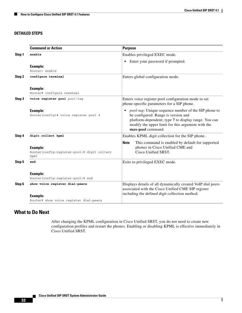
Enabling KPML for SIP PhonesPerform the following steps to enable KPML digit collection on a SIP phone.
Restrictions
• This feature is supported only on Cisco Unified IP Phone 7911G, 7941G, 7941GE, 7961G, 7961GE, 7970G, and 7971GE.
• A dial plan assigned to a phone has priority over KPML.
SUMMARY STEPS
1. enable
2. configure terminal
3. voice register pool pool-tag
4. digit collect kpml
5. end
6. show voice register dial-peer
31Cisco Unified SIP SRST System Administrator Guide
Cisco Unified SIP SRST 4.1How to Configure Cisco Unified SIP SRST 4.1 Features
DETAILED STEPS
What to Do Next
After changing the KPML configuration in Cisco Unified SRST, you do not need to create new configuration profiles and restart the phones. Enabling or disabling KPML is effective immediately in Cisco Unified SRST.
Command or Action Purpose
Step 1 enable
Example:Router> enable
Enables privileged EXEC mode.
• Enter your password if prompted.
Step 2 configure terminal
Example:Router# configure terminal
Enters global configuration mode.
Step 3 voice register pool pool-tag
Example:Router(config)# voice register pool 4
Enters voice register pool configuration mode to set phone-specific parameters for a SIP phone.
• pool-tag: Unique sequence number of the SIP phone to be configured. Range is version and platform-dependent; type ? to display range. You can modify the upper limit for this argument with the max-pool command.
Step 4 digit collect kpml
Example:Router(config-register-pool)# digit collect kpml
Enables KPML digit collection for the SIP phone.
Note This command is enabled by default for supported phones in Cisco Unified CME and Cisco Unified SRST.
Step 5 end
Example:Router(config-register-pool)# end
Exits to privileged EXEC mode.
Step 6 show voice register dial-peers
Example:Router# show voice register dial-peers
Displays details of all dynamically created VoIP dial peers associated with the Cisco Unified CME SIP register including the defined digit collection method.
32Cisco Unified SIP SRST System Administrator Guide

Cisco Unified SIP SRST 4.1How to Configure Cisco Unified SIP SRST 4.1 Features
Disabling SIP Supplementary Services for Call Forward and Call TransferPerform the following steps to disable REFER messages for call transfers and redirect responses for call forwarding from being sent to the destination by Cisco Unified SRST. You can disable these supplementary features if the destination gateway does not support them.
Restrictions
Disabling supplementary services is supported only when all endpoints are SCCP or all endpoints are SIP. It does not support a mix of SCCP and SIP endpoints.
SUMMARY STEPS
1. enable
2. configure terminal
3. voice service voip or dial-peer voice tag voip
4. no supplementary-service sip {moved-temporarily | refer}
5. end
DETAILED STEPS
Command or Action Purpose
Step 1 enable
Example:Router> enable
Enables privileged EXEC mode.
• Enter your password if prompted.
Step 2 configure terminal
Example:Router# configure terminal
Enters global configuration mode.
Step 3 voice service voip
or
dial-peer voice tag voip
Example:Router(config)# voice service voip
or
Router(config)# dial-peer voice 99 voip
Enters voice-service configuration mode to set global parameters for VoIP features.
or
Enters dial peer configuration mode to set parameters for a specific dial peer.
33Cisco Unified SIP SRST System Administrator Guide

Cisco Unified SIP SRST 4.1How to Configure Cisco Unified SIP SRST 4.1 Features
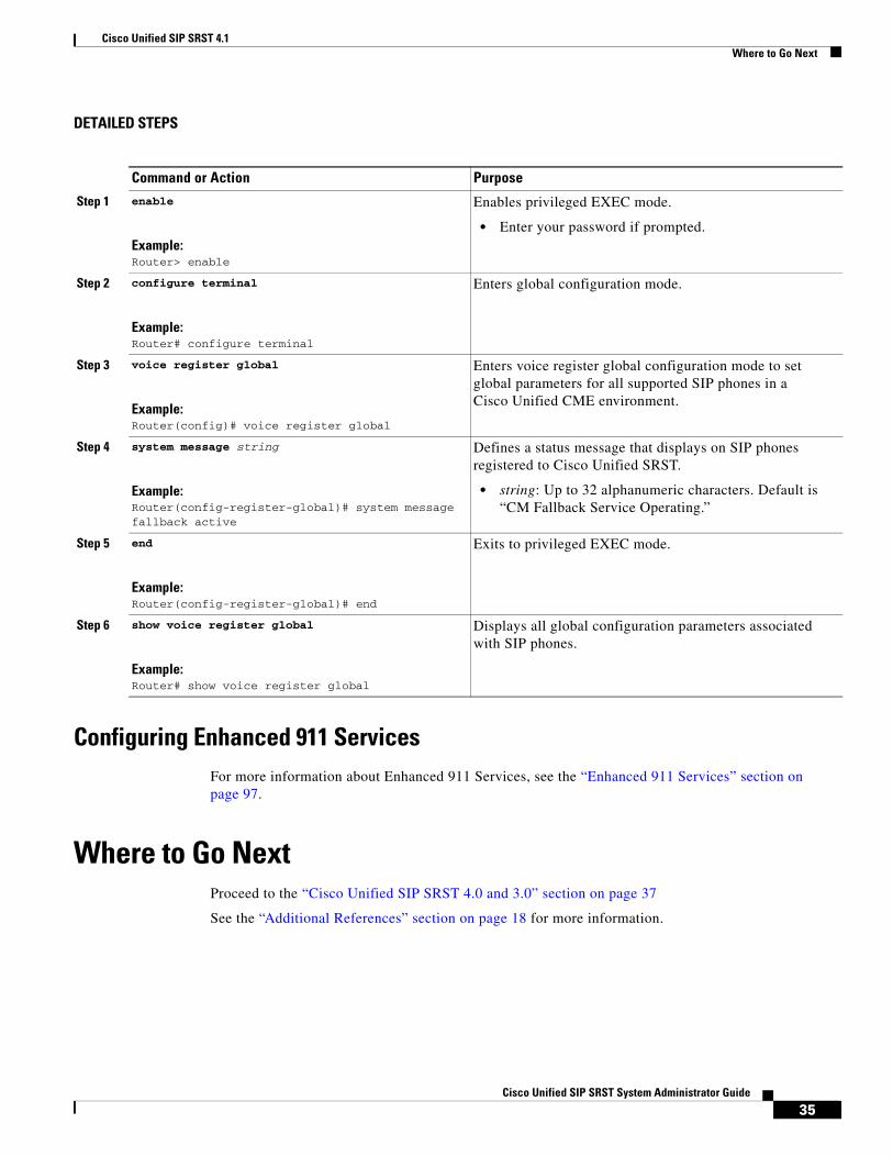
Configuring Idle Prompt Status for SIP PhonesPerform the following steps to customize the message that displays on SIP phones after the phones failover to Cisco Unified SRST.
Note You do not need to create new configuration files with the create profile command and restart the phones after changing the idle status message in Cisco Unified SRST. Modifying the status message takes effect immediately in Cisco Unified SRST.
Prerequisites
Cisco Unified SRST 4.1 or a later version.
SUMMARY STEPS
1. enable
2. configure terminal
3. voice register global
4. system message string
5. end
6. show voice register global
Step 4 no supplementary-service sip {moved-temporarily | refer}
Example:Router(conf-voi-serv)# no supplementary-service sip refer
or
Router(config-dial-peer)# no supplementary-service sip refer
Disables SIP call forwarding or call transfer supplementary services globally or for a dial peer.
• moved-temporarily: SIP redirect response for call forwarding.
• refer: SIP REFER message for call transfers.
• Sending REFER and redirect messages to the destination is the default behavior.
Note This command is supported for calls between SIP phones and calls between SCCP phones. It is not supported for a mixture of SCCP and SIP endpoints.
Step 5 end
Example:Router(config-voi-serv)# end
or
Router(config-dial-peer)# end
Exits to privileged EXEC mode.
Command or Action Purpose
34Cisco Unified SIP SRST System Administrator Guide
Cisco Unified SIP SRST 4.1Where to Go Next
DETAILED STEPS
Configuring Enhanced 911 ServicesFor more information about Enhanced 911 Services, see the “Enhanced 911 Services” section on page 97.
Where to Go NextProceed to the “Cisco Unified SIP SRST 4.0 and 3.0” section on page 37
See the “Additional References” section on page 18 for more information.
Command or Action Purpose
Step 1 enable
Example:Router> enable
Enables privileged EXEC mode.
• Enter your password if prompted.
Step 2 configure terminal
Example:Router# configure terminal
Enters global configuration mode.
Step 3 voice register global
Example:Router(config)# voice register global
Enters voice register global configuration mode to set global parameters for all supported SIP phones in a Cisco Unified CME environment.
Step 4 system message string
Example:Router(config-register-global)# system message fallback active
Defines a status message that displays on SIP phones registered to Cisco Unified SRST.
• string: Up to 32 alphanumeric characters. Default is “CM Fallback Service Operating.”
Step 5 end
Example:Router(config-register-global)# end
Exits to privileged EXEC mode.
Step 6 show voice register global
Example:Router# show voice register global
Displays all global configuration parameters associated with SIP phones.
35Cisco Unified SIP SRST System Administrator Guide

Cisco Unified SIP SRST 4.1Where to Go Next
36Cisco Unified SIP SRST System Administrator Guide

Cisco Unified SIP SRST 4.0 and 3.0
This chapter describes the following tasks:
• Running Cisco Session Initiation Protocol (SIP) Cisco Unified Survivable Remote Site Telephony (Cisco Unified SRST) 3.0 for the first time
• Running Cisco Unified SIP SRST 4.0 for the first time
• Upgrading from Cisco Unified SIP SRST 3.0 to Cisco Unified SIP SRST 4.0
Note that upgrades from Cisco Unified SIP SRST 3.4 to Cisco Unified SIP SRST 4.0 are not impacted by the issues discussed in this chapter.
Contents • Comparison of Cisco Unified SIP SRST 3.0 and Cisco Unified SIP SRST 4.0, page 37
• Configuration and Upgrade Tasks, page 38
• How to Upgrade from Cisco Unified SIP SRST 3.0 to Cisco Unified SIP SRST 4.0, page 40
• Where to Go Next, page 43
Comparison of Cisco Unified SIP SRST 3.0 and Cisco Unified SIP SRST 4.0
Cisco Unified SIP SRST 3.0, Cisco IOS Release 12.2(15)ZJ to Cisco IOS Release 12.4
Cisco SIP SRST 3.0 was a predecessor to Cisco Unified SIP SRST 4.0. In Cisco SIP SRST 3.0, you could configure a Cisco IOS voice gateway to act as a SIP redirect server. The voice gateway would respond to the originator of a call with a SIP Redirect message, and the Redirect message allowed the SIP phone that originated the call to establish a call to its destination. In addition, several commands in voice register pool configuration mode were introduced that allowed registration permission control.
Cisco Unified SIP SRST V4.0, Cisco IOS Release 12.4(4)XC
With Cisco Unified SIP SRST 4.0, a SIP redirect server is not necessary. Instead, a back-to-back user agent (B2BUA) server routes the call as desired. A B2BUA is a separate call agent that has more features than a redirect server, which can accept and forward calls only. With a B2BUA you can also configure call blocking and call forwarding. In call forwarding, the B2BUA forwards calls on behalf of the phone, while maintaining a presence as call middleman in the call path.
37Cisco Unified SIP SRST System Administrator Guide
OL-13143-03

Cisco Unified SIP SRST 4.0 and 3.0Configuration and Upgrade Tasks
Configuration and Upgrade TasksThe following table lists the high-level steps that you need to take to configure and upgrade Cisco Unified SIP SRST 4.0. It also lists the high-level steps to run Version 3.0 or 4.0.
Table 5 Configuring Procedures for Cisco Unified SIP SRST Version
Cisco Unified SIP SRST Version Instructions and Procedures
If you are interested in Cisco Unified SIP SRST 3.0 (using a redirect server), complete these procedures.
Cisco Unified SIP SRST Version 3.0 provides a backup to an external SIP proxy server by providing basic registrar and redirect services. The following chapters provide full Version 3.0 information, including basic voice register pool configurations.
• Configuring the SIP Registrar, page 46
• Configuring Backup Registrar Service to SIP Phones, page 48
• Configuring Cisco Unified SIP SRST Features Using Redirect Mode, page 59
38Cisco Unified SIP SRST System Administrator Guide

Cisco Unified SIP SRST 4.0 and 3.0Configuration and Upgrade Tasks
If you are interested in Cisco Unified SIP SRST 4.0 (using a B2BUA) and have never used Cisco Unified SIP SRST in the past, complete these procedures.
VoIP-to-VoIP connections permit the termination and reorigination of transferred and forwarded calls over the VoIP network. The following task describes how to allow SIP connections:
• Enabling SIP-to-SIP Connection Capabilities, page 42
SIP registrar functionality in Cisco IOS software is a required part of Cisco Unified SIP SRST. A registrar accepts SIP Register requests and dynamically builds VoIP dial peers, allowing the Cisco IOS voice gateway software to route calls to SIP phones. The following task describes how to configure the SIP registrar:
• Configuring the SIP Registrar, page 45
Configure a basic voice register pool:
• Configuring Backup Registrar Service to SIP Phones, page 48
You are now ready to configure Version 4.0 features such as call blocking and call forwarding. The following chapter describes the call blocking and call forwarding configurations:
• Configuring Cisco Unified SIP SRST Features Using Back-to-Back User Agent Mode, page 67
If you are currently running Version 3.0 and want to upgrade to Version 4.0, complete these procedures.
Since Version 4.0 uses a B2BUA and not a redirect server, call redirection must be disabled as described in the following task:
• Disabling Call Redirection, page 40
VoIP-to-VoIP connections permit the termination and reorigination of transferred and forwarded calls over the VoIP network. The following task describes how to allow SIP connections:
• Enabling SIP-to-SIP Connection Capabilities, page 42
You are now ready to configure Version 4.0 features such as call blocking and call forwarding. The following chapter describes the call blocking and call forwarding configurations:
• Configuring Cisco Unified SIP SRST Features Using Back-to-Back User Agent Mode, page 67
Cisco Unified SIP SRST Version Instructions and Procedures
39Cisco Unified SIP SRST System Administrator Guide
Cisco Unified SIP SRST 4.0 and 3.0How to Upgrade from Cisco Unified SIP SRST 3.0 to Cisco Unified SIP SRST 4.0
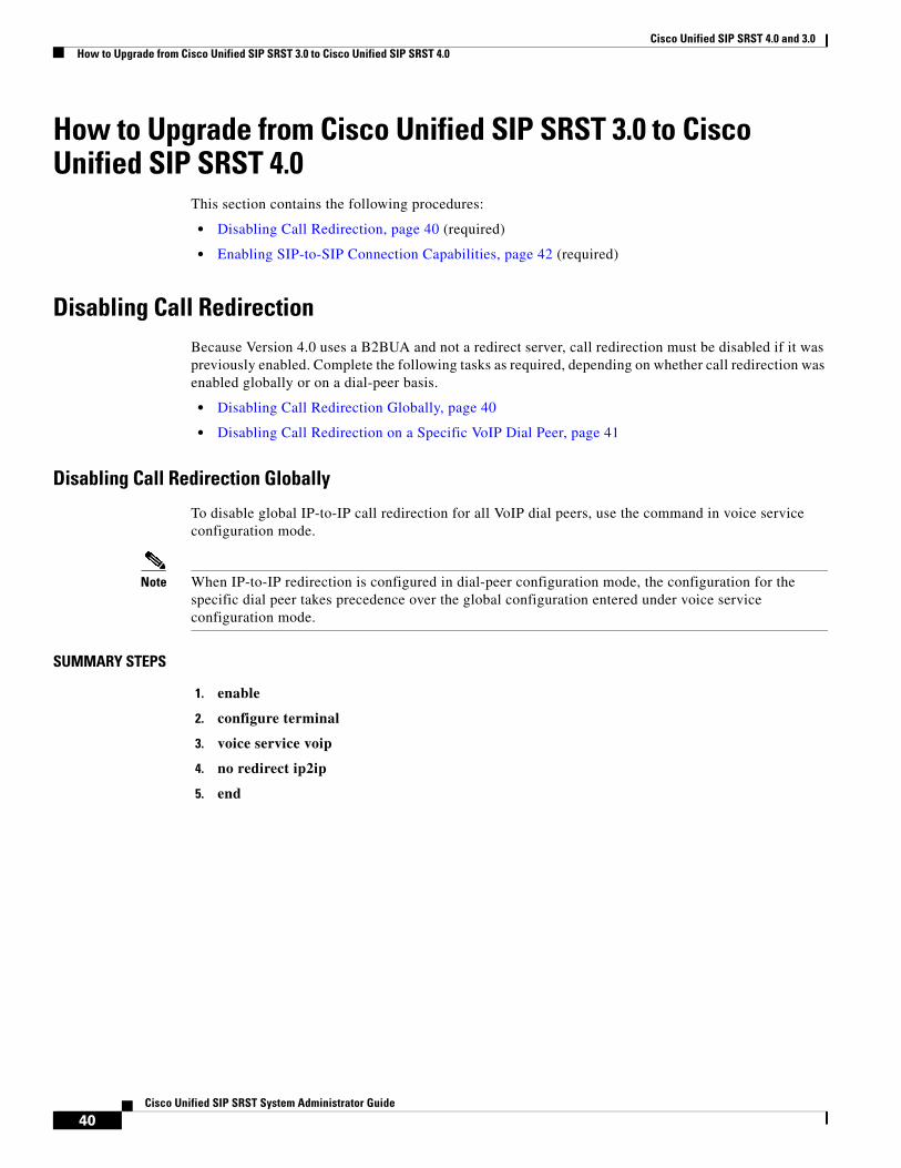
How to Upgrade from Cisco Unified SIP SRST 3.0 to Cisco Unified SIP SRST 4.0
This section contains the following procedures:
• Disabling Call Redirection, page 40 (required)
• Enabling SIP-to-SIP Connection Capabilities, page 42 (required)
Disabling Call Redirection Because Version 4.0 uses a B2BUA and not a redirect server, call redirection must be disabled if it was previously enabled. Complete the following tasks as required, depending on whether call redirection was enabled globally or on a dial-peer basis.
• Disabling Call Redirection Globally, page 40
• Disabling Call Redirection on a Specific VoIP Dial Peer, page 41
Disabling Call Redirection Globally
To disable global IP-to-IP call redirection for all VoIP dial peers, use the command in voice service configuration mode.
Note When IP-to-IP redirection is configured in dial-peer configuration mode, the configuration for the specific dial peer takes precedence over the global configuration entered under voice service configuration mode.
SUMMARY STEPS
1. enable
2. configure terminal
3. voice service voip
4. no redirect ip2ip
5. end
40Cisco Unified SIP SRST System Administrator Guide

Cisco Unified SIP SRST 4.0 and 3.0How to Upgrade from Cisco Unified SIP SRST 3.0 to Cisco Unified SIP SRST 4.0
DETAILED STEPS
Disabling Call Redirection on a Specific VoIP Dial Peer
To disable IP-to-IP call redirection for a specific VoIP dial peer, disable it on the inbound dial peer where it was originally enabled.
Note When IP-to-IP redirection is configured in dial-peer configuration mode, the configuration for the specific dial peer takes precedence over the global configuration entered under voice service configuration mode.
SUMMARY STEPS
1. enable
2. configure terminal
3. dial-peer voice tag voip
4. no redirect ip2ip
5. end
Command or Action Purpose
Step 1 enable
Example:Router> enable
Enables privileged EXEC mode.
• Enter your password if prompted.
Step 2 configure terminal
Example:Router# configure terminal
Enters global configuration mode.
Step 3 voice service voip
Example:Router(config)# voice service voip
Enters voice service configuration mode.
Step 4 no redirect ip2ip
Example:Router(config-voi-srv)# no redirect ip2ip
Disables redirection of SIP phone calls to SIP phone calls globally using the Cisco IOS voice gateway.
Step 5 end
Example:Router(config-voi-srv)# end
Returns to privileged EXEC mode.
41Cisco Unified SIP SRST System Administrator Guide

Cisco Unified SIP SRST 4.0 and 3.0How to Upgrade from Cisco Unified SIP SRST 3.0 to Cisco Unified SIP SRST 4.0
DETAILED STEPS
Enabling SIP-to-SIP Connection CapabilitiesVoIP-to-VoIP connections permit the termination and reorigination of transferred and forwarded calls over the VoIP network. For Cisco Unified SIP SRST 4.0 we enable SIP-to-SIP connections for hairpin call routing. The B2BUA that routes the call uses the SIP-to-SIP connection. Because VoIP-to-VoIP connections are disabled on the router by default, they must be explicitly enabled to use call routing.
SUMMARY STEPS
1. enable
2. configure terminal
3. voice service voip
4. allow-connections sip to sip
5. end
Command or Action Purpose
Step 1 enable
Example:Router> enable
Enables privileged EXEC mode.
• Enter your password if prompted.
Step 2 configure terminal
Example:Router# configure terminal
Enters global configuration mode.
Step 3 dial-peer voice tag voip
Example:Router(config)# dial-peer voice 25 voip
Enters dial-peer configuration mode.
• tag: A number that uniquely identifies the dial peer (this number has local significance only).
• voip: Indicates that this is a VoIP peer using voice encapsulation on the POTS network and is used for configuring redirect.
Step 4 no redirect ip2ip
Example:Router(config-dial-peer)# no redirect ip2ip
Disables redirection of SIP phone calls to SIP phone calls on a specific VoIP dial peer using the Cisco IOS voice gateway.
Step 5 end
Example:Router(config-dial-peer)# end
Returns to privileged EXEC mode.
42Cisco Unified SIP SRST System Administrator Guide

Cisco Unified SIP SRST 4.0 and 3.0Where to Go Next
DETAILED STEPS
Where to Go NextSIP registrar functionality in Cisco IOS software is a required part of Cisco Unified SIP SRST. By default, Cisco Unified SIP SRST is not enabled and cannot accept SIP register messages. To configure the SIP registrar to accept incoming SIP Register messages, see the “Configuring the SIP Registrar” section on page 45.
To configure a basic voice register pool, see the “Configuring Backup Registrar Service to SIP Phones” section on page 48.
To configure call forwarding or call blocking, see the “Configuring Cisco Unified SIP SRST Features Using Back-to-Back User Agent Mode” section on page 67.
See the “Additional References” section on page 18 for more information.
Command or Action Purpose
Step 1 enable
Example:Router> enable
Enables privileged EXEC mode.
• Enter your password if prompted.
Step 2 configure terminal
Example:Router# configure terminal
Enters global configuration mode.
Step 3 voice service voip
Example:Router(config)# voice service voip
Enters voice service configuration mode to establish global call transfer and forwarding parameters.
Step 4 allow-connections sip to sip
Example:Router(config-voi-srv)# allow-connections sip to sip
Enables VoIP-to-VoIP call connections. Use the no form of the command to disable VoIP-to-VoIP connections, which is the default.
Step 5 end
Example:Router(conf-voi-serv)# end
Returns to privileged EXEC mode.
43Cisco Unified SIP SRST System Administrator Guide

Cisco Unified SIP SRST 4.0 and 3.0Where to Go Next
44Cisco Unified SIP SRST System Administrator Guide

Configuring the SIP Registrar
Session Initiation Protocol (SIP) registrar functionality in Cisco IOS software is an essential part of Cisco Unified SIP Survivable Remote Site Telephony (SRST). According to RFC 2543, a SIP registrar is a server that accepts Register requests and is typically collocated with a proxy or redirect server. A SIP registrar may also offer location services.
ContentsThis section contains the following procedures:
• Prerequisites for Configuring the SIP Registrar, page 45
• Restrictions for Configuring the SIP Registrar, page 45
• Information About Configuring the SIP Registrar, page 45
• How to Configure the SIP Registrar, page 46
• Where to Go Next, page 58
Prerequisites for Configuring the SIP RegistrarComplete the prerequisites documented in the “Prerequisites for Configuring Cisco Unified SIP SRST” section in the “Cisco Unified SIP SRST Feature Overview” chapter.
Restrictions for Configuring the SIP RegistrarSee the restrictions documented in the “Restrictions for Configuring Cisco Unified SIP SRST” section in the “Cisco Unified SIP SRST Feature Overview” chapter.
Information About Configuring the SIP RegistrarCisco Unified SIP SRST provides backup to an external SIP proxy server by providing basic registrar and redirect services. These services are used by a SIP IP phone in the event of a WAN connection outage when the SIP phone is unable to communicate with its primary SIP proxy. The Cisco Unified SIP SRST device also provides PSTN gateway access for placing and receiving PSTN calls.
45Cisco Unified SIP SRST System Administrator Guide
OL-13143-03
Configuring the SIP RegistrarHow to Configure the SIP Registrar
To make maximum use of the Cisco Unified SIP SRST service, the local SIP IP phones should support dual (concurrent) registration with both their primary SIP proxy or registrar and the Cisco Unified SIP SRST backup registrar. Cisco Unified SIP SRST works for the following types of calls:
• Local SIP IP phone to local SIP phone, if the main proxy is unavailable.
• Additional services like class of restriction (COR) for local SIP IP phones to the outgoing PSTN. For example, to block outgoing 1-900 numbers.
How to Configure the SIP RegistrarThis section contains the following procedures:
• Configuring the SIP Registrar, page 46 (required)
• Configuring Backup Registrar Service to SIP Phones, page 48 (required)
• Configuring Backup Registrar Service to SIP Phones (Using Optional Commands), page 51 (optional)
• Verifying SIP Registrar Configuration, page 55 (optional)
• Verifying Proxy Dial-Peer Configuration, page 56 (optional)
Configuring the SIP RegistrarThe local SIP gateway that becomes the SIP registrar acts as a backup SIP proxy or redirector and accepts SIP Register messages from SIP phones. It becomes a location database of local SIP IP phones that are set up for dual registration. Dual registration allows SIP IP phones to simultaneously register with both their primary and their fallback registrar devices. That is, when a SIP IP phone registers with a Cisco Unified SIP SRST gateway, it simultaneously registers with the main proxy and SIP redirect server for coverage in case of a WAN failure.
A registrar accepts SIP Register requests and dynamically builds VoIP dial peers, allowing the Cisco IOS voice gateway software to route calls to SIP phones.
If a SIP Register request has a Contact header that includes a DNS address, the Contact header is resolved before the contact is added to the SIP registrar database. This is done because during a WAN failure (and the resulting Cisco Unified SIP SRST functionality), DNS servers may not be available.
SIP registrar functionality is enabled with the following configuration. By default, Cisco Unified SIP SRST is not enabled and cannot accept SIP Register messages. The following configuration must be set up to accept incoming SIP Register messages.
Prerequisites
The SIP endpoints (IP phones) must support dual concurrent registration, which is registering with the main SIP proxy and the Cisco Unified SIP SRST device (redirect server) at the same time. If this requirement is not met, the Cisco Unified SIP SRST device cannot route incoming calls to the SIP phone. For configuration instructions, see the Cisco SIP IP Phone Software documents on Cisco.com.
SUMMARY STEPS
1. enable
2. configure terminal
46Cisco Unified SIP SRST System Administrator Guide
OL-13143-03
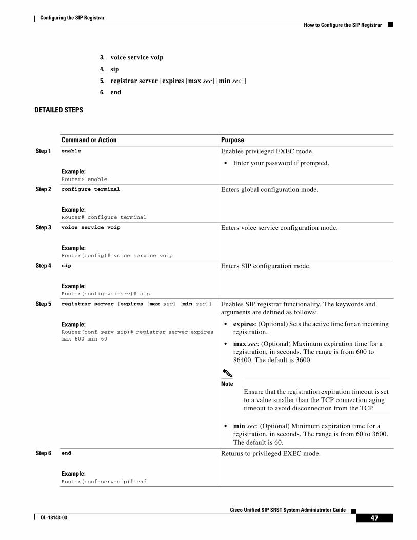
Configuring the SIP RegistrarHow to Configure the SIP Registrar
3. voice service voip
4. sip
5. registrar server [expires [max sec] [min sec]]
6. end
DETAILED STEPS
Command or Action Purpose
Step 1 enable
Example:Router> enable
Enables privileged EXEC mode.
• Enter your password if prompted.
Step 2 configure terminal
Example:Router# configure terminal
Enters global configuration mode.
Step 3 voice service voip
Example:Router(config)# voice service voip
Enters voice service configuration mode.
Step 4 sip
Example:Router(config-voi-srv)# sip
Enters SIP configuration mode.
Step 5 registrar server [expires [max sec] [min sec]]
Example:Router(conf-serv-sip)# registrar server expires max 600 min 60
Enables SIP registrar functionality. The keywords and arguments are defined as follows:
• expires: (Optional) Sets the active time for an incoming registration.
• max sec: (Optional) Maximum expiration time for a registration, in seconds. The range is from 600 to 86400. The default is 3600.
Note Ensure that the registration expiration timeout is set to a value smaller than the TCP connection aging timeout to avoid disconnection from the TCP.
• min sec: (Optional) Minimum expiration time for a registration, in seconds. The range is from 60 to 3600. The default is 60.
Step 6 end
Example:Router(conf-serv-sip)# end
Returns to privileged EXEC mode.
47Cisco Unified SIP SRST System Administrator Guide
OL-13143-03

Configuring the SIP RegistrarHow to Configure the SIP Registrar
What to Do Next
For incoming SIP Register messages to be successfully accepted, users must also set up a voice register pool. See the “Configuring Backup Registrar Service to SIP Phones” section on page 48.
Configuring Backup Registrar Service to SIP PhonesBackup registrar service to SIP IP phones can be provided by configuring a voice register pool on SIP gateways. The voice register pool configuration provides registration permission control and can also be used to configure some dial-peer attributes that are applied to the dynamically created VoIP dial peers when SIP phone registrations match the pool. The following call types are supported:
• SIP IP phone to or from
– Local PSTN
– Local analog FXS phones
– Local SIP IP phone (using VoIP-to-VoIP dial-peer redirect)
The commands in the configuration below provide registration permission control and set up a basic voice register pool. The pool gives users control over which registrations are accepted by a Cisco Unified SIP SRST device and which can be rejected. Registrations that match this pool create VoIP SIP dial peers with the dial-peer attributes set to these configurations. Although only the id command is mandatory, this configuration example shows basic functionality.
For command-level information, see the appropriate command page in the Cisco Unified SRST and Cisco Unified SIP SRST Command Reference (All Versions).
Prerequisites
• The SIP registrar must be configured before a voice register pool is set up. See the “Configuring the SIP Registrar” section on page 46 for complete instructions.
Restrictions
• The id command identifies the individual SIP IP phone or sets of SIP IP phones that are to be configured. Thus, the id command configured in Step 5 is required and must be configured before any other voice register pool commands. When the mac address keyword and argument are used, the IP phone must be in the same subnet as that of the router’s LAN interface, such that the phone’s MAC address is visible in the router’s Address Resolution Protocol (ARP) cache. Once a MAC address is configured for a specific voice register pool, remove the existing MAC address before changing to a new MAC address.
• Proxy dial peers are autogenerated dial peers that route all calls from the PSTN to Cisco Unified SIP SRST. When a SIP phone registers to Cisco Unified SIP SRST and the proxy command is enabled, two dial peers are automatically created. The first dial peer routes to the proxy, and the second (or fallback) dial peer routes to the SIP phone. The same functionality can also be achieved with the appropriate creation of static dial peers (manually creating dial peers that point to the proxy). Proxy dial peers can be monitored to one proxy IP address, only. That is, only one proxy from a voice registration pool can be monitored at a time. If more than one proxy address needs to be monitored, you must manually create and configure additional dial peers.
48Cisco Unified SIP SRST System Administrator Guide
OL-13143-03

Configuring the SIP RegistrarHow to Configure the SIP Registrar
Note To monitor SIP proxies, the call fallback active command must be configured, as described in Step 3.
SUMMARY STEPS
1. enable
2. configure terminal
3. call fallback active
4. voice register pool tag
5. id {network address mask mask | ip address mask mask | mac address}
6. preference preference-order
7. proxy ip-address [preference value] [monitor probe {icmp-ping | rtr} [alternate-ip-address]]
8. voice-class codec tag
9. application application-name
10. end
DETAILED STEPS
Command or Action Purpose
Step 1 enable
Example:Router> enable
Enables privileged EXEC mode.
• Enter your password if prompted.
Step 2 configure terminal
Example:Router# configure terminal
Enters global configuration mode.
Step 3 call fallback active
Example:Router(config)# call fallback active
(Optional) Enables a call request to fall back to alternate dial peers in case of network congestion.
• This command is used if you want to monitor the proxy dial peer and fallback to the next preferred dial peer. For full information on the call fallback active command, see the PSTN Fallback Feature.
Step 4 voice register pool tag
Example:Router(config)# voice register pool 12
Enters voice register pool configuration mode for SIP phones.
• Use this command to control which registrations are accepted or rejected by a Cisco Unified SIP SRST device.
49Cisco Unified SIP SRST System Administrator Guide
OL-13143-03

Configuring the SIP RegistrarHow to Configure the SIP Registrar
Step 5 id {network address mask mask | ip address mask mask | mac address}
Example:Router(config-register-pool)# id network 172.16.0.0 mask 255.255.0.0
Explicitly identifies a locally available individual or set of SIP IP phones. The keywords and arguments are defined as follows:
• network address mask mask: The network address mask mask keyword/argument combination is used to accept SIP Register messages for the indicated phone numbers from any IP phone within the indicated IP subnet.
• ip address mask mask: The ip address mask mask keyword/argument combination is used to identify an individual phone.
• mac address: MAC address of a particular Cisco Unified IP Phone.
Step 6 preference preference-order
Example:Router(config-register-pool)# preference 2
Sets the preference order for the VoIP dial peers to be created. Range is from 0 to 10. Default is 0, which is the highest preference.
• The preference must be greater (lower priority) than the preference configured with the preference keyword in the proxy command.
Step 7 proxy ip-address [preference value] [monitor probe {icmp-ping | rtr} [alternate-ip-address]]
Example:Router(config-register-pool)# proxy 10.2.161.187 preference 1
Autogenerates additional VoIP dial peers to reach the main SIP proxy whenever a Cisco Unified SIP IP Phone registers with a Cisco Unified SIP SRST gateway. The keywords and arguments are defined as follows:
• ip-address: IP address of the SIP proxy.
• preference value: (Optional) Defines the preference of the proxy dial peers that are created. The preference must be less (higher priority) than the preference configured with the preference command.
Range is from 0 to 10. The highest preference is 0. There is no default.
• monitor probe: (Optional) Enables monitoring of proxy dial peers.
• icmp-ping: Enables monitoring of proxy dial peers using ICMP ping.
Note The dial peer on which the probe is configured will be excluded from call routing only for outbound calls. Inbound calls can arrive through this dial peer.
• rtr: Enables monitoring of proxy dial peers using RTR probes.
• alternate-ip-address: (Optional) Enables monitoring of alternate IP addresses other than the proxy address. For example, to monitor a gateway front end to a SIP proxy.
Command or Action Purpose
50Cisco Unified SIP SRST System Administrator Guide
OL-13143-03

Configuring the SIP RegistrarHow to Configure the SIP Registrar
What to Do Next
There are several more voice register pool commands that add functionality, but that are not required. See the “Configuring Backup Registrar Service to SIP Phones (Using Optional Commands)” section on page 51 for these commands.
Configuring Backup Registrar Service to SIP Phones (Using Optional Commands)
The prior configurations set up a basic voice register pool. The configuration in this procedure adds optional attributes to increase functionality.
Prerequisites
• Prerequisites as described in the “Configuring Backup Registrar Service to SIP Phones” section on page 48.
• Configuration of the required commands as described in the “Configuring Backup Registrar Service to SIP Phones” section on page 48.
SUMMARY STEPS
1. enable
2. configure terminal
3. voice register pool tag
4. translate-outgoing {called | calling} rule-tag
5. alias tag pattern to target [preference value]
6. cor {incoming | outgoing} cor-list-name {cor-list-number starting-number [- ending-number] | default}
7. incoming called-number [number]
Step 8 voice-class codec tag
Example:Router(config-register-pool)# voice-class codec 15
Sets the voice class codec parameters. The tag argument is a codec group number between 1 and 10000.
Step 9 application application-name
Example:Router(config-register-pool)# application SIP.App
Selects the session-level application on the VoIP dial peer. Use the application-name argument to define a specific interactive voice response (IVR) application.
Step 10 end
Example:Router(config-register-pool)# end
Returns to privileged EXEC mode.
Command or Action Purpose
51Cisco Unified SIP SRST System Administrator Guide
OL-13143-03

Configuring the SIP RegistrarHow to Configure the SIP Registrar
8. max registrations value
9. number tag number-pattern {preference value} [huntstop]
10. dtmf-relay [cisco-rtp] [rtp-nte] [sip-notify]
11. end
DETAILED STEPS
Command or Action Purpose
Step 1 enable
Example:Router> enable
Enables privileged EXEC mode.
• Enter your password if prompted.
Step 2 configure terminal
Example:Router# configure terminal
Enters global configuration mode.
Step 3 voice register pool tag
Example:Router(config)# voice register pool 12
Enters voice register pool configuration mode.
• Use this command to control which registrations are accepted or rejected by a Cisco Unified SIP SRST device.
Step 4 translate-outgoing {called | calling} rule-tag
Example:Router(config-register-pool)# translate-outgoing called 1
Allows explicit setting of translation rules on the VoIP dial peer to modify a phone number dialed by a Cisco Unified IP Phone user.
• The rule-tag argument is the reference number of the translation rule. Valid entries are 1 to 2147483647.
Step 5 alias tag pattern to target [preference value]
Example:Router(config-register-pool)# alias 1 94... to 91011 preference 8
Allows Cisco Unified SIP IP Phones to handle inbound PSTN calls to telephone numbers that are unavailable when the main proxy is not available. The keywords and arguments are defined as follows:
• tag: Number from 1 to 5 and the distinguishing factor when there are multiple alias commands.
• pattern: The prefix number; matches the incoming telephone number and may include wildcards.
• to: Connects the tag number pattern to the alternate number.
• target: The target number; an alternate telephone number to route incoming calls to match the number pattern.
• preference value: (Optional) Assigns a dial-peer preference value to the alias. The value argument is the value of the associated dial peer, and the range is from 1 to 10. There is no default.
52Cisco Unified SIP SRST System Administrator Guide
OL-13143-03

Configuring the SIP RegistrarHow to Configure the SIP Registrar
Step 6 cor {incoming | outgoing} cor-list-name {cor-list-number starting-number [- ending-number] | default}
Example:Router(config-register-pool)# cor incoming call91 1 91011
Configures a class of restriction (COR) on the VoIP dial peers associated with directory numbers. COR specifies which incoming dial peers can use which outgoing dial peers to make a call. Each dial peer can be provisioned with an incoming and outgoing COR list. The keywords and arguments are defined as follows:
• incoming: COR list to be used by incoming dial peers.
• outgoing: COR list to be used by outgoing dial peers.
• cor-list-name: COR list name.
• cor-list-number: COR list identifier. The maximum number of COR lists that can be created is four, comprised of incoming or outgoing dial peers.
• starting-number: Start of a directory number range, if an ending number is included. Can also be a standalone number.
• (Optional) Indicator that a full range is configured.
• ending-number: (Optional) End of a directory number range.
• default: Instructs the router to use an existing default COR list.
Step 7 incoming called-number [number]
Example:Router(config-register-pool)# incoming called-number 308
Applies incoming called parameters to dynamically created dial peers. The number argument is optional and indicates a sequence of digits that represent a phone number prefix.
Step 8 number tag number-pattern [preference value] [huntstop]
Example:Router(config-register-pool)# number 1 50.. preference 2
Indicates the E.164 phone numbers that the registrar permits to handle the Register message from the Cisco Unified SIP IP Phone. The keywords and arguments are defined as follows:
• tag: Number from 1 to 10 and the distinguishing factor when there are multiple number commands.
• number-pattern: Phone numbers (including wildcards and patterns) that are permitted by the registrar to handle the Register message from the SIP IP phone.
• preference value: (Optional) Defines the number list preference order.
• huntstop: (Optional) Stops hunting if the dial peer is busy.
Command or Action Purpose
53Cisco Unified SIP SRST System Administrator Guide
OL-13143-03
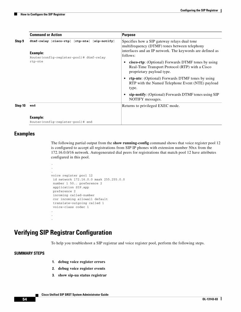
Configuring the SIP RegistrarHow to Configure the SIP Registrar
Examples
The following partial output from the show running-config command shows that voice register pool 12 is configured to accept all registrations from SIP IP phones with extension number 50xx from the 172.16.0.0/16 network. Autogenerated dial peers for registrations that match pool 12 have attributes configured in this pool.
.
.
.voice register pool 12 id network 172.16.0.0 mask 255.255.0.0 number 1 50.. preference 2 application SIP.app preference 2 incoming called-number cor incoming allowall default translate-outgoing called 1 voice-class codec 1...
Verifying SIP Registrar ConfigurationTo help you troubleshoot a SIP registrar and voice register pool, perform the following steps.
SUMMARY STEPS
1. debug voice register errors
2. debug voice register events
3. show sip-ua status registrar
Step 9 dtmf-relay [cisco-rtp] [rtp-nte] [sip-notify]
Example:Router(config-register-pool)# dtmf-relay rtp-nte
Specifies how a SIP gateway relays dual tone multifrequency (DTMF) tones between telephony interfaces and an IP network. The keywords are defined as follows:
• cisco-rtp: (Optional) Forwards DTMF tones by using Real-Time Transport Protocol (RTP) with a Cisco proprietary payload type.
• rtp-nte: (Optional) Forwards DTMF tones by using RTP with the Named Telephone Event (NTE) payload type.
• sip-notify: (Optional) Forwards DTMF tones using SIP NOTIFY messages.
Step 10 end
Example:Router(config-register-pool)# end
Returns to privileged EXEC mode.
Command or Action Purpose
54Cisco Unified SIP SRST System Administrator Guide
OL-13143-03
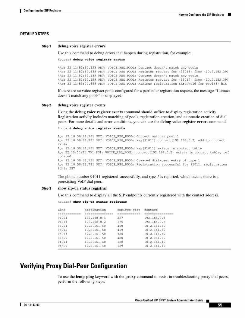
Configuring the SIP RegistrarHow to Configure the SIP Registrar
DETAILED STEPS
Step 1 debug voice register errors
Use this command to debug errors that happen during registration, for example:
Router# debug voice register errors
*Apr 22 11:52:54.523 PDT: VOICE_REG_POOL: Contact doesn't match any pools *Apr 22 11:52:54.539 PDT: VOICE_REG_POOL: Register request for (33015) from (10.2.152.39) *Apr 22 11:52:54.539 PDT: VOICE_REG_POOL: Contact doesn't match any pools. *Apr 22 11:52:54.559 PDT: VOICE_REG_POOL: Register request for (33017) from (10.2.152.39)*Apr 22 11:53:04.559 PDT: VOICE_REG_POOL: Maximum registration threshold for pool(3) hit
If there are no voice register pools configured for a particular registration request, the message “Contact doesn’t match any pools” is displayed.
Step 2 debug voice register events
Using the debug voice register events command should suffice to display registration activity. Registration activity includes matching of pools, registration creation, and automatic creation of dial peers. For more details and error conditions, you can use the debug voice register errors command.
Router# debug voice register events
Apr 22 10:50:21.731 PDT: VOICE_REG_POOL: Contact matches pool 1Apr 22 10:50:21.731 PDT: VOICE_REG_POOL: key(91011) contact(192.168.0.2) add to contact table Apr 22 10:50:21.731 PDT: VOICE_REG_POOL: key(91011) exists in contact table Apr 22 10:50:21.731 PDT: VOICE_REG_POOL: contact(192.168.0.2) exists in contact table, ref updated Apr 22 10:50:21.731 PDT: VOICE_REG_POOL: Created dial-peer entry of type 1 Apr 22 10:50:21.731 PDT: VOICE_REG_POOL: Registration successful for 91011, registration id is 257
The phone number 91011 registered successfully, and type 1 is reported, which means there is a preexisting VoIP dial peer.
Step 3 show sip-ua status registrar
Use this command to display all the SIP endpoints currently registered with the contact address.
Router# show sip-ua status registrar
Line destination expires(sec) contact============ =============== ============ ===============91021 192.168.0.3 227 192.168.0.3 91011 192.168.0.2 176 192.168.0.2 95021 10.2.161.50 419 10.2.161.50 95012 10.2.161.50 419 10.2.161.50 95011 10.2.161.50 420 10.2.161.50 95500 10.2.161.50 420 10.2.161.50 94011 10.2.161.40 128 10.2.161.40 94500 10.2.161.40 129 10.2.161.40
Verifying Proxy Dial-Peer ConfigurationTo use the icmp-ping keyword with the proxy command to assist in troubleshooting proxy dial peers, perform the following steps.
55Cisco Unified SIP SRST System Administrator Guide
OL-13143-03

Configuring the SIP RegistrarHow to Configure the SIP Registrar
SUMMARY STEPS
1. configure terminal
2. voice register pool tag
3. proxy ip-address [preference value] [monitor probe {icmp-ping | rtr} [alternate-ip-address]]
4. end
5. show voice register dial-peers
6. show dial-peer voice
DETAILED STEPS
Step 1 configure terminal
Use this command to enter global configuration mode.
Router# configure terminal
Step 2 voice register pool tag
Use this command to enter voice register pool configuration mode.
Router(config)# voice register pool 1
Step 3 proxy ip-address [preference value] [monitor probe {icmp-ping | rtr} [alternate-ip-address]]
Set the proxy command to monitor with icmp-ping:
Router(config-register-pool)# proxy 10.2.161.187 preference 1 monitor probe icmp-ping
Step 4 end
Returns to privileged EXEC mode.
Router(config-register-pool)# end
Step 5 show voice register dial-peers
Use this command to verify dial-peer configurations, and notice that icmp-ping monitoring is set.
Router# show voice register dial-peers
dial-peer voice 40035 voippreference 5destination-pattern 91011redirect ip2ipsession target ipv4:192.168.0.2session protocol sipv2voice-class codec 1
dial-peer voice 40036 voippreference 1destination-pattern 91011redirect ip2ipsession target ipv4:10.2.161.187session protocol sipv2voice-class codec 1monitor probe icmp-ping 10.2.161.187
Step 6 show dial-peer voice
56Cisco Unified SIP SRST System Administrator Guide
OL-13143-03

Configuring the SIP RegistrarHow to Configure the SIP Registrar
Use the show dial-peer voice command on dial peer 40036, and notice the monitor probe status.
Note Also highlighted is the output of the cor and incoming called-number commands.
Router# show dial-peer voice
VoiceOverIpPeer40036peer type = voice, information type = voice,description = `',tag = 40036, destination-pattern = `91011',answer-address = `', preference=1,CLID Restriction = NoneCLID Network Number = `'CLID Second Number sent source carrier-id = `', target carrier-id = `',source trunk-group-label = `', target trunk-group-label = `',numbering Type = `unknown'group = 40036, Admin state is up, Operation state is up,incoming called-number = `', connections/maximum = 0/unlimited, ! Default output for incoming called-number commandDTMF Relay = disabled,modem transport = system,huntstop = disabled,in bound application associated: 'DEFAULT'out bound application associated: ''dnis-map = permission :bothincoming COR list:maximum capability ! Default output for cor commandoutgoing COR list:minimum requirement ! Default output for cor commandTranslation profile (Incoming):Translation profile (Outgoing):incoming call blocking:translation-profile = `'disconnect-cause = `no-service'advertise 0x40 capacity_update_timer 25 addrFamily 4 oldAddrFamily 4type = voip, session-target = `ipv4:10.2.161.187',technology prefix: settle-call = disabledip media DSCP = ef, ip signaling DSCP = af31,ip video rsvp-none DSCP = af41,ip video rsvp-pass DSCP = af41ip video rsvp-fail DSCP = af41,UDP checksum = disabled,session-protocol = sipv2, session-transport = system,req-qos = best-effort, acc-qos = best-effort,req-qos video = best-effort, acc-qos video = best-effort,req-qos audio def bandwidth = 64, req-qos audio max bandwidth = 0,req-qos video def bandwidth = 384, req-qos video max bandwidth = 0, RTP dynamic payload type values: NTE = 101Cisco: NSE=100, fax=96, fax-ack=97, dtmf=121, fax-relay=122CAS=123, ClearChan=125, PCM switch over u-law=0,A-law=8RTP comfort noise payload type = 19fax rate = voice, payload size = 20 bytesfax protocol = systemfax-relay ecm enablefax NSF = 0xAD0051 (default)codec = g729r8, payload size = 20 bytes,Media Setting = flow-through (global)Expect factor = 0, Icpif = 20,Playout Mode is set to adaptive,Initial 60 ms, Max 300 ms
57Cisco Unified SIP SRST System Administrator Guide
OL-13143-03

Configuring the SIP RegistrarWhere to Go Next
Playout-delay Minimum mode is set to default, value 40 ms Fax nominal 300 msMax Redirects = 1, signaling-type = cas,VAD = enabled, Poor QOV Trap = disabled, Source Interface = NONEvoice class sip url = system,voice class sip rel1xx = system,redirect ip2ip = enabledmonitor probe method: icmp-ping ip address: 10.2.161.187, Monitored destination reachablevoice class perm tag = `'Time elapsed since last clearing of voice call statistics neverConnect Time = 0, Charged Units = 0,Successful Calls = 0, Failed Calls = 0, Incomplete Calls = 0Accepted Calls = 0, Refused Calls = 0,Last Disconnect Cause is "",Last Disconnect Text is "",Last Setup Time = 0.
Where to Go NextTo configure Cisco Unified SIP SRST redirect mode, features see the “Configuring Cisco Unified SIP SRST Features Using Redirect Mode” chapter.
To configure Cisco Unified SIP SRST call forwarding and call blocking features, see the “Configuring Cisco Unified SIP SRST Features Using Back-to-Back User Agent Mode” chapter.
See the “Additional References” section on page 18 for more information.
58Cisco Unified SIP SRST System Administrator Guide
OL-13143-03

Configuring Cisco Unified SIP SRST Features Using Redirect Mode
Note This chapter applies to version 3.0 only.
This chapter describes Cisco Unified Session Initiation Protocol (SIP) Survivable Remote Site Telephony (SRST) features using redirect mode.
Contents • Prerequisites for Cisco Unified SIP SRST Features Using Redirect Mode, page 59
• Restrictions for Cisco Unified SIP SRST Features Using Redirect Mode, page 59
• Information About Cisco Unified SIP SRST Features Using Redirect Mode, page 60
• How to Configure Cisco Unified SIP SRST Features Using Redirect Mode, page 60
• Configuration Examples for Cisco Unified SIP SRST Features Using Redirect Mode, page 64
• Where to Go Next, page 66
Prerequisites for Cisco Unified SIP SRST Features Using Redirect Mode
Complete the prerequisites documented in the “Prerequisites for Configuring Cisco Unified SIP SRST” section in the “Cisco Unified SIP SRST Feature Overview” chapter.
Restrictions for Cisco Unified SIP SRST Features Using Redirect Mode
See the restrictions documented in the “Restrictions for Configuring Cisco Unified SIP SRST” section in the “Cisco Unified SIP SRST Feature Overview” chapter.
59Cisco Unified SIP SRST System Administrator Guide
OL-13143-03

Configuring Cisco Unified SIP SRST Features Using Redirect ModeInformation About Cisco Unified SIP SRST Features Using Redirect Mode
Information About Cisco Unified SIP SRST Features Using Redirect Mode
Cisco Unified SIP SRST provides backup to an external SIP proxy server by providing basic registrar and redirect services. These services are used by a SIP IP phone in the event of a WAN connection outage when the SIP phone is unable to communicate with its primary SIP proxy. The Cisco Unified SIP SRST device also provides PSTN gateway access for placing and receiving PSTN calls.
To make maximum use of the Cisco Unified SIP SRST service, the local SIP IP phones should support dual (concurrent) registration with both their primary SIP proxy or registrar and the Cisco Unified SIP SRST backup registrar. Cisco Unified SIP SRST works for the following types of calls:
• Local SIP IP phone to local SIP phone, if the main proxy is unavailable.
• Additional services like class of restriction (COR) for local SIP IP phones to the outgoing PSTN. For example, to block outgoing 1-900 numbers.
How to Configure Cisco Unified SIP SRST Features Using Redirect Mode
This section contains the following procedures:
• Configuring Call Redirect Enhancements to Support Calls Between SIP IP Phones for Cisco Unified SIP SRST, page 60 (required)
• Configuring Sending 300 Multiple Choice Support, page 63 (required)
Configuring Call Redirect Enhancements to Support Calls Between SIP IP Phones for Cisco Unified SIP SRST
The call redirect enhancement supports calls from a local SIP phone to another local SIP phone through the Cisco IOS voice gateway. Prior to this enhancement, an attempt by a SIP phone to contact another local SIP phone using the Cisco IOS voice gateway as if it were a SIP proxy or redirect server would fail. However, now the Cisco IOS voice gateway can act as a SIP redirect server. The voice gateway responds to the originator with a SIP Redirect message, allowing the SIP phone that originated the call to establish a call to its destination.
The redirect ip2ip (voice service) and redirect ip2ip (dial-peer) commands allow you to enable the SIP functionality, globally or on a specific inbound dial peer. The default application on Cisco Unified SIP SRST supports IP-to-IP redirection.
• Configuring Call Redirect Enhancements to Support Calls Globally, page 61
• Configuring Call Redirect Enhancements to Support Calls on a Specific VoIP Dial Peer, page 62
60Cisco Unified SIP SRST System Administrator Guide

Configuring Cisco Unified SIP SRST Features Using Redirect ModeHow to Configure Cisco Unified SIP SRST Features Using Redirect Mode
Configuring Call Redirect Enhancements to Support Calls Globally
To enable global IP-to-IP call redirection for all VoIP dial peers, use voice service configuration mode.
Note When IP-to-IP redirection is configured in dial-peer configuration mode, the configuration for the specific dial peer takes precedence over the global configuration entered under voice service configuration mode.
SUMMARY STEPS
1. enable
2. configure terminal
3. voice service voip
4. redirect ip2ip
5. end
DETAILED STEPS
Command or Action Purpose
Step 1 enable
Example:Router> enable
Enables privileged EXEC mode.
• Enter your password if prompted.
Step 2 configure terminal
Example:Router# configure terminal
Enters global configuration mode.
Step 3 voice service voip
Example:Router(config)# voice service voip
Enters voice service configuration mode.
Step 4 redirect ip2ip
Example:Router(config-voi-srv)# redirect ip2ip
Redirects SIP phone calls to SIP phone calls globally on a gateway using the Cisco IOS voice gateway.
Step 5 end
Example:Router(config-voi-srv)# end
Returns to privileged EXEC mode.
61Cisco Unified SIP SRST System Administrator Guide

Configuring Cisco Unified SIP SRST Features Using Redirect ModeHow to Configure Cisco Unified SIP SRST Features Using Redirect Mode
Configuring Call Redirect Enhancements to Support Calls on a Specific VoIP Dial Peer
To enable IP-to-IP call redirection for a specific VoIP dial peer, configure it on an inbound dial peer in dial-peer configuration mode. The default application on Cisco Unified SIP SRST supports IP-to-IP redirection.
Note When IP-to-IP redirection is configured in dial-peer configuration mode, the configuration for the specific dial peer takes precedence over the global configuration entered under voice service configuration mode.
Restrictions
The redirect ip2ip command must be configured on an inbound dial peer of the gateway.
SUMMARY STEPS
1. enable
2. configure terminal
3. dial-peer voice tag voip
4. application application-name
5. redirect ip2ip
6. end
DETAILED STEPS
Command or Action Purpose
Step 1 enable
Example:Router> enable
Enables privileged EXEC mode.
• Enter your password if prompted.
Step 2 configure terminal
Example:Router# configure terminal
Enters global configuration mode.
Step 3 dial-peer voice tag voip
Example:Router(config)# dial-peer voice 25 voip
Enters dial-peer configuration mode.
• tag—A number that uniquely identifies the dial peer (this number has local significance only).
• voip—Indicates that this is a VoIP peer using voice encapsulation on the POTS network and is used for configuring redirect.
62Cisco Unified SIP SRST System Administrator Guide

Configuring Cisco Unified SIP SRST Features Using Redirect ModeHow to Configure Cisco Unified SIP SRST Features Using Redirect Mode
Configuring Sending 300 Multiple Choice SupportPrior to Cisco IOS Release 12.2(15)ZJ, when a call was redirected, the SIP gateway would send a 302 Moved Temporarily message. The first longest match route on a gateway (dial-peer destination pattern) was used in the Contact header of the 302 message. With Release 12.2(15)ZJ, if multiple routes to a destination exist for a redirected number (multiple dial peers are matched), the SIP gateway sends a 300 Multiple Choice message, and the multiple routes in the Contact header are listed.
The configuration below allows users to choose the order in which the routes appear in the Contact header.
SUMMARY STEPS
1. enable
2. configure terminal
3. voice service voip
4. sip
5. redirect contact order [best-match | longest-match]
6. end
Step 4 application application-name
Example:Router(config-dial-peer)# application session
Enables a specific application on a dial peer.
• For SIP, the default Tool Command Language (Tcl) application (from the Cisco IOS image) is session and can be applied to both VoIP and POTS dial peers.
• The application must support IP-to-IP redirection.
Step 5 redirect ip2ip
Example:Router(config-dial-peer)# redirect ip2ip
Redirects SIP phone calls to SIP phone calls on a specific VoIP dial peer using the Cisco IOS voice gateway.
Step 6 end
Example:Router(config-dial-peer)# end
Returns to privileged EXEC mode.
Command or Action Purpose
63Cisco Unified SIP SRST System Administrator Guide

Configuring Cisco Unified SIP SRST Features Using Redirect ModeConfiguration Examples for Cisco Unified SIP SRST Features Using Redirect Mode
DETAILED STEPS
Configuration Examples for Cisco Unified SIP SRST Features Using Redirect Mode
This section provides the following configuration example:
• Cisco Unified SIP SRST: Example, page 65
I
Command or Action Purpose
Step 1 enable
Example:Router> enable
Enables privileged EXEC mode.
• Enter your password if prompted.
Step 2 configure terminal
Example:Router# configure terminal
Enters global configuration mode.
Step 3 voice service voip
Example:Router(config)# voice service voip
Enters voice service configuration mode.
Step 4 sip
Example:Router(config-voi-srv)# sip
Enters SIP configuration mode.
Step 5 redirect contact order [best-match | longest- match]
Example:Router(conf-serv-sip)# redirect contact order best-match
Sets the order of contacts in the 300 Multiple Choice message. The keywords are defined as follows:
• best-match—(Optional) Uses the current system configuration to set the order of contacts.
• longest-match—(Optional) Sets the contact order by using the destination pattern longest match first, and then the second longest match, the third longest match, and so on. This is the default.
Step 6 end
Example:Router(config-serv-sip)# end
Returns to privileged EXEC mode.
64Cisco Unified SIP SRST System Administrator Guide

Configuring Cisco Unified SIP SRST Features Using Redirect ModeConfiguration Examples for Cisco Unified SIP SRST Features Using Redirect Mode
Cisco Unified SIP SRST: ExampleThis section provides a configuration example to match the configuration tasks in the previous sections.
!! Sets up the registrar server and enables IP-to-IP redirection and 300 ! Multiple Choice support.!voice service voip redirect ip2ip sip registrar server expires max 600 min 60 redirect contact order best-match!! Configures the voice-class codec with G.711uLaw and G729 codecs. The codecs are! applied to the voice register pools.!voice class codec 1 codec preference 1 g711ulaw codec preference 2 g729br8!! The voice register pools define various pools that are used to match! incoming REGISTER requests and create corresponding dial peers.!voice register pool 1 id mac 0030.94C2.A22A preference 5 cor incoming call91 1 91011 translate-outgoing called 1 proxy 10.2.161.187 preference 1 monitor probe icmp-ping alias 1 94... to 91011 preference 8 voice-class codec 1!voice register pool 2 id ip 192.168.0.3 mask 255.255.255.255 preference 5 cor outgoing call95 1 91021 proxy 10.2.161.187 preference 1 voice-class codec 1!voice register pool 3 id network 10.2.161.0 mask 255.255.255.0 number 1 95... preference 1 preference 5 cor incoming call95 1 95011 cor outgoing call95 1 95011 proxy 10.2.161.187 preference 1 monitor probe icmp-ping max registrations 5 voice-class codec 1!voice register pool 4 id network 10.2.161.0 mask 255.255.255.0 number 1 94... preference 1 preference 5 cor incoming everywhere default cor outgoing everywhere default proxy 10.2.161.187 preference 1 max registrations 2 voice-class codec 1!! Configures translation rules to be applied in the voice register pools.!translation-rule 1
65Cisco Unified SIP SRST System Administrator Guide

Configuring Cisco Unified SIP SRST Features Using Redirect ModeWhere to Go Next
Rule 0 94 91!! Sets up proxy monitoring.!call fallback active!dial-peer cor custom name 95 name 94 name 91!! Configures COR values to be applied to the voice register pool.!dial-peer cor list call95 member 95!dial-peer cor list call94 member 94!dial-peer cor list call91 member 91!dial-peer cor list everywhere member 95 member 94 member 91!! Configures a voice port and a POTS dial peer for calls to and from the PSTN endpoints.voice-port 1/0/0!dial-peer voice 91500 pots corlist incoming call91 corlist outgoing call91 destination-pattern 91500 port 1/0/0!
Where to Go NextAfter configuring basic Cisco Unified SIP SRST, the “Configuring Cisco Unified SIP SRST Features Using Back-to-Back User Agent Mode” chapter describes additional configurations to increase SIP phone functionality.
66Cisco Unified SIP SRST System Administrator Guide

Configuring Cisco Unified SIP SRST Features Using Back-to-Back User Agent Mode
Note The chapter applies to versions 4.0 and 3.4 only.
This chapter describes Cisco Unified Survivable Remote Site Telephony (Cisco Unified SRST) support for standardized RFC 3261 features for SIP phones. Features include call blocking and call forwarding.
Contents • Prerequisites for Cisco Unified SIP SRST Features Using Back-to-Back User Agent Mode, page 67
• Restrictions for Cisco Unified SIP SRST Features Using Back-to-Back User Agent Mode, page 68
• Information About Cisco Unified SIP SRST Features Using Back-to-Back User Agent Mode, page 68
• How to Configure Cisco Unified SIP SRST, page 70
• Configuration Examples for Cisco Unified SIP SRST Features Using Back-to-Back User Agent Mode, page 79
• Where to Go Next, page 81
Prerequisites for Cisco Unified SIP SRST Features Using Back-to-Back User Agent Mode
• Complete the prerequisites documented in the “Prerequisites for Configuring Cisco Unified SIP SRST” section in the “Cisco Unified SIP SRST Feature Overview” chapter.
• Complete the necessary tasks found in the “Cisco Unified SIP SRST 4.0 and 3.0” chapter. Specific tasks include the required task that is documented in the “Enabling SIP-to-SIP Connection Capabilities” section on page 42.
• Configure the SIP registrar. The SIP registrar gives users control of accepting or rejecting registrations. To configure acceptance of incoming SIP Register messages, see the “Configuring the SIP Registrar” section on page 46.
67Cisco Unified SIP SRST System Administrator Guide
OL-13143-03

Configuring Cisco Unified SIP SRST Features Using Back-to-Back User Agent ModeRestrictions for Cisco Unified SIP SRST Features Using Back-to-Back User Agent Mode
Restrictions for Cisco Unified SIP SRST Features Using Back-to-Back User Agent Mode
See the restrictions documented in the “Restrictions for Configuring Cisco Unified SIP SRST” section in the “Cisco Unified SIP SRST Feature Overview” chapter.
Information About Cisco Unified SIP SRST Features Using Back-to-Back User Agent Mode
A Cisco Unified SRST system can now support SIP phones with standard-based RFC 3261 feature support locally and across SIP WAN networks. With Cisco Unified SIP SRST, SIP phones can place calls across SIP networks with similar features, as SCCP phones do. For example, most SCCP phone features such as caller ID, speed dial, and redial are supported now on SIP networks, which gives users the opportunity to choose SCCP or SIP.
Cisco Unified SIP SRST also uses a back-to-back user agent (B2BUA), which is a separate call agent that has more features than Cisco SIP SRST 3.0, which used a redirect server that only accepted and forwarded calls. The main advantage of a B2BUA call agent is in call forwarding, because it forwards calls on behalf of the phone. In addition, it maintains a presence as call middleman in the call path.
Cisco SIP SRST 3.4 supports the following call combinations:
• SIP phone to SIP phone
• SIP phone to PSTN / router voice port
• SIP phone to SCCP phone
See Figure 1 on page 12 and Figure 2 on page 13 for an illustration of Cisco Unified SIP SRST using a B2BUA.
Cisco Unified SIP SRST and Cisco SIP Communications Manager Express Feature Crossover
Cisco Unified SIP SRST uses is a voice register dn configuration mode. However, in a typical Cisco Unified SIP SRST setup, voice register dn commands are not used, so they are not discussed in this book. Although you are not restricted from using voice register dn commands, they are not likely to be needed in a Cisco Unified SIP SRST environment. The voice register dn commands are most likely to be used in a Cisco Unified SIP Communications Manager Express (CME) environment. If you work in a Cisco Unified SIP CME environment and would like to know which commands are also applicable to Cisco Unified SIP SRST, Table 6 lists Version 3.4 commands for CME and SRST. Commands marked under the column “Cisco (SIP) CME Mode Only” show up if mode cme is configured in voice register global configuration mode; these commands apply to Cisco CME only.
Procedures for configuring Cisco Unified SIP CME and complete descriptions of all CME and voice register dn commands are found in documents on the Cisco Unified Communications Manager (CallManager) page on Cisco.com.
Note Table 6 is not all-inclusive; additional commands may exist.
68Cisco Unified SIP SRST System Administrator Guide

Configuring Cisco Unified SIP SRST Features Using Back-to-Back User Agent ModeInformation About Cisco Unified SIP SRST Features Using Back-to-Back User Agent Mode
Table 6 Version 3.4 New or Enhanced Commands for Cisco Unified SRST and Cisco Unified
CME (Sorted by Configuration Mode)
CommandDial Peer
Voice Register Mode
Configurable for Cisco Unified (SIP ) CME and Cisco Unified SIP SRST
Applicable to Cisco Unified (SIP) CME Only
after-hour exempt X dn X —
auto-answer — dn — X
call forward X dn X —
huntstop X dn X —
label — dn — X
name — dn — X
number X dn X —
preference X dn X —
application X global X —
authenticate — global — X
create — global — X
date-format — global — X
dst — global — X
external ring — global X —
file — global — X
hold-alert — global — X
load — global — X
logo — global — X
max-dn — global X —
max-pool — global X —
max-redirect — global — X
mode — global X —
mwi — global — X
reset — global — X
tftp-path — global — X
timezone — global — X
upgrade — global — X
url — global — X
voicemail — global — X
after-hour exempt X pool X —
application X pool X —
call-forward — pool X —
call-waiting — pool — X
codec X pool X —
69Cisco Unified SIP SRST System Administrator Guide

Configuring Cisco Unified SIP SRST Features Using Back-to-Back User Agent ModeHow to Configure Cisco Unified SIP SRST
How to Configure Cisco Unified SIP SRSTThis section contains the following procedures:
• Configuring SIP Phone Features, page 71 (optional)
• Configuring SIP-to-SIP Call Forwarding, page 73 (required)
• Configuring Call Blocking Based on Time of Day, Day of Week, or Date, page 75 (required)
• SIP Call Hold and Resume, page 79 (no configuration necessary)
description — pool — X
dnd-control — pool — X
dtmf-relay — pool X —
id — pool X —
keep-conference — pool — X
max-pool — pool X —
number X pool X —
preference X pool X —
proxy X pool X —
reset — pool — X
speed-dial — pool — X
template — pool — X
translate-outgoing X pool X —
type — pool — X
username — pool — X
vad X pool X —
anonymous — template — X
caller-id — template — X
conference — template — X
dnd-control — template — X
forward — template — X
transfer — template — X
Table 6 Version 3.4 New or Enhanced Commands for Cisco Unified SRST and Cisco Unified
CME (Sorted by Configuration Mode) (continued)
CommandDial Peer
Voice Register Mode
Configurable for Cisco Unified (SIP ) CME and Cisco Unified SIP SRST
Applicable to Cisco Unified (SIP) CME Only
70Cisco Unified SIP SRST System Administrator Guide

Configuring Cisco Unified SIP SRST Features Using Back-to-Back User Agent ModeHow to Configure Cisco Unified SIP SRST
Configuring SIP Phone FeaturesAfter a voice register pool has been set, this procedure adds optional features to increase functionality. Some features can be made per pool or globally.
In voice register pool configuration, you can now configure several new options per pool (a pool can be one phone or a group of phones). There is also a new voice register global configuration mode for Cisco Unified SIP SRST. In voice register global mode, you can globally assign characteristics to phones.
SUMMARY STEPS
1. enable
2. configure terminal
3. voice register global tag
4. max-pool max-voice-register-pools
5. application application-name
6. external ring {bellcore-dr1 | bellcore-dr2 | bellcore-dr3 | bellcore-dr4 | bellcore-dr5}
7. exit
8. voice register pool tag
9. no vad
10. codec codec-type [bytes]
11. end
DETAILED STEPS
Command or Action Purpose
Step 1 enable
Example:Router> enable
Enables privileged EXEC mode.
• Enter your password if prompted.
Step 2 configure terminal
Example:Router# configure terminal
Enters global configuration mode.
Step 3 voice register global tag
Example:Router(config)# voice register global 12
Enters voice register global configuration mode to set global parameters for all supported Cisco SIP IP phones in a Cisco Unified SIP SRST environment.
71Cisco Unified SIP SRST System Administrator Guide

Configuring Cisco Unified SIP SRST Features Using Back-to-Back User Agent ModeHow to Configure Cisco Unified SIP SRST
Step 4 max-pool max-voice-register-pools
Example:Router(config-register-global)# max-pool 10
Sets the maximum number of SIP voice register pools that are supported in a Cisco Unified SIP SRST environment. The max-voice-register-pools argument represents the maximum number of SIP voice register pools supported by the Cisco Unified SIP SRST router. The upper limit of voice register pools is version- and platform-dependent; see Cisco IOS command-line interface (CLI) help. Default is 0.
Step 5 application application-name
Example:Router(config-register-global)# application global_app
Selects the session-level application for all dial peers associated with SIP phones. Use the application-name argument to define a specific interactive voice response (IVR) application.
Step 6 external-ring {bellcore-dr1 | bellcore-dr2 | bellcore-dr3 | bellcore-dr4 | bellcore-dr5}
Example:Router(config-register-global)# external-ring bellcore-dr1
Specifies the type of ring sound used on Cisco SIP or Cisco SCCP IP phones for external calls. Each bellcore-dr 1-5 keyword supports standard distinctive ringing patterns as defined in the standard GR-506-CORE, LSSGR: Signaling for Analog Interfaces.
Step 7 exit
Example:Router(config-register-global)# exit
Exits voice register global configuration mode.
Step 8 voice register pool tag
Example:Router(config)# voice register pool 20
Enters voice register pool configuration mode for SIP phones.
• Use this command to control which phone registrations are to be accepted or rejected by a Cisco Unified SIP SRST device.
Step 9 no vad
Example:Router(config-register-pool)# no vad
Disables voice activity detection (VAD) on the VoIP dial peer.
• VAD is enabled by default. Because there is no comfort noise during periods of silence, the call may seem to be disconnected. You may prefer to set no vad on the SIP phone pool.
Command or Action Purpose
72Cisco Unified SIP SRST System Administrator Guide

Configuring Cisco Unified SIP SRST Features Using Back-to-Back User Agent ModeHow to Configure Cisco Unified SIP SRST
Configuring SIP-to-SIP Call ForwardingSIP-to-SIP call forwarding (call routing) is available. Call forwarding is provided either by the phone or by using a back-to-back user agent (B2BUA), which allows call forwarding on any dial peer. Calls into a SIP device may be forwarded to other SIP or SCCP devices (including Cisco Unity, third-party voice-mail systems, or an auto attendant or IVR system such as IPCC and IPCC Express). In addition, SCCP IP phones may be forwarded to SIP phones.
Cisco Unity or other voice messaging systems connected by a SIP trunk or SIP user agent are able to pass a message-waiting indicator (MWI) when a message is left. The SIP phone then displays the MWI when indicated by the voice messaging system.
Note SIP-to-H.323 call forwarding is not supported.
To configure SIP-to-SIP call forwarding, you must first allow connections between specific types of endpoints in a Cisco IP-to-IP gateway. The allow-connections command grants this capability. For more information on setting the allow-connections command, see the “Enabling SIP-to-SIP Connection Capabilities” section on page 42. Once the SIP-to-SIP connections are allowed, you can configure call forwarding under an individual SIP phone pool. Any of the following commands can be used to configure call forwarding, according to your needs:
• Under voice register pool
– call-forward b2bua all directory-number
– call-forward b2bua busy directory-number
– call-forward b2bua mailbox directory-number
– call-forward b2bua noan directory-number [timeout seconds]
In a typical Cisco Unified SIP SRST setup, the call-forward b2bua mailbox command is not used; however it is likely to be used in a Cisco Unified SIP Communications Manager Express (CME) environment. Detailed procedures for configuring the call-forward b2bua mailbox command are found in Cisco Unified Communications Manager (CallManager) documentation on Cisco.com.
Step 10 codec codec-type [bytes]
Example:Router(config-register-pool)# codec g729r8
Specifies the codec supported by a single SIP phone or a VoIP dial peer in a Cisco Unified SIP SRST environment. The codec-type argument specifies the preferred codec and can be one of the following:
• g711alaw: G.711 a–law 64,000 bps.
• g711ulaw: G.711 mu–law 64,000 bps.
• g729r8: G.729 8000 bps (default).
The bytes argument is optional and specifies the number of bytes in the voice payload of each frame
Step 11 end
Example:Router(config-register-pool)# end
Returns to privileged EXEC mode.
Command or Action Purpose
73Cisco Unified SIP SRST System Administrator Guide
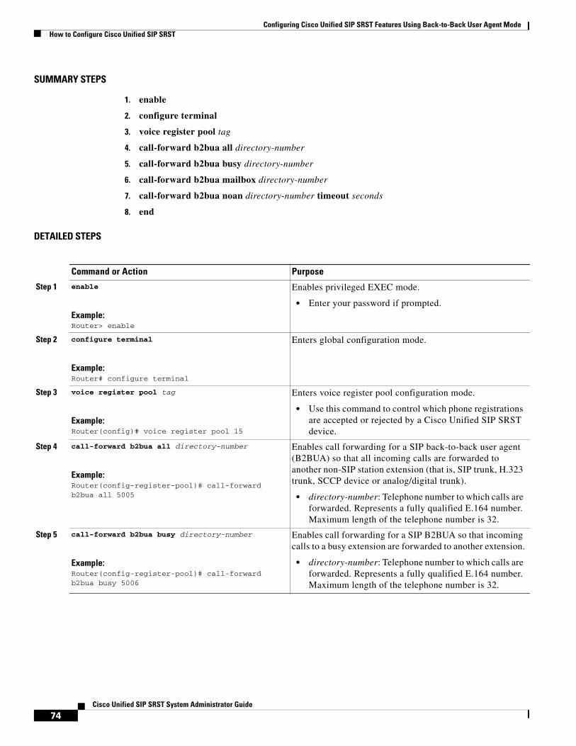
Configuring Cisco Unified SIP SRST Features Using Back-to-Back User Agent ModeHow to Configure Cisco Unified SIP SRST
SUMMARY STEPS
1. enable
2. configure terminal
3. voice register pool tag
4. call-forward b2bua all directory-number
5. call-forward b2bua busy directory-number
6. call-forward b2bua mailbox directory-number
7. call-forward b2bua noan directory-number timeout seconds
8. end
DETAILED STEPS
Command or Action Purpose
Step 1 enable
Example:Router> enable
Enables privileged EXEC mode.
• Enter your password if prompted.
Step 2 configure terminal
Example:Router# configure terminal
Enters global configuration mode.
Step 3 voice register pool tag
Example:Router(config)# voice register pool 15
Enters voice register pool configuration mode.
• Use this command to control which phone registrations are accepted or rejected by a Cisco Unified SIP SRST device.
Step 4 call-forward b2bua all directory-number
Example:Router(config-register-pool)# call-forward b2bua all 5005
Enables call forwarding for a SIP back-to-back user agent (B2BUA) so that all incoming calls are forwarded to another non-SIP station extension (that is, SIP trunk, H.323 trunk, SCCP device or analog/digital trunk).
• directory-number: Telephone number to which calls are forwarded. Represents a fully qualified E.164 number. Maximum length of the telephone number is 32.
Step 5 call-forward b2bua busy directory-number
Example:Router(config-register-pool)# call-forward b2bua busy 5006
Enables call forwarding for a SIP B2BUA so that incoming calls to a busy extension are forwarded to another extension.
• directory-number: Telephone number to which calls are forwarded. Represents a fully qualified E.164 number. Maximum length of the telephone number is 32.
74Cisco Unified SIP SRST System Administrator Guide

Configuring Cisco Unified SIP SRST Features Using Back-to-Back User Agent ModeHow to Configure Cisco Unified SIP SRST
Configuring Call Blocking Based on Time of Day, Day of Week, or DateCall blocking prevents the unauthorized use of phones and is implemented by matching a pattern of up to 32 digits during a specified time of day, day of week, or date. Cisco Unified SIP SRST provides SIP endpoints the same time-based call blocking mechanism that is currently provided for SCCP phones. The call blocking feature supports all incoming calls, including incoming SIP and analog FXS calls.
Note Pin-based exemptions and the “Login” toll-bar override are not supported in Cisco Unified SIP SRST.
The commands used for SIP phone call blocking are the same commands that are used for SCCP phones on your Cisco Unified SRST system. The Cisco SRST session application accesses the current after-hours configuration under call-manager-fallback mode and applies it to calls originated by Cisco SIP phones that are registered to the Cisco SRST router. The commands used in call-manager-fallback mode that set block criteria (time/date/block pattern) are the following:
• after-hours block pattern pattern-tag pattern [7-24]
• after-hours day day start-time stop-time
• after-hours date month date start-time stop-time
Step 6 call-forward b2bua mailbox directory-number
Example:Router(config-register-pool)# call-forward b2bua mailbox 5007
Controls the specific voice-mail box selected in a voice-mail system at the end of a call forwarding exchange.
• directory-number: Telephone number to which calls are forwarded when the forwarded destination is busy or does not answer. Represents a fully qualified E.164 number. Maximum length of the telephone number is 32.
Step 7 call-forward b2bua noan directory-number timeout seconds
Example:Router(config-register-pool)# call-forward b2bua noan 5010 timeout 10
Enables call forwarding for a SIP B2BUA so that incoming calls to an extension that does not answer after a configured amount of time are forwarded to another extension.
This command is used if a phone is registered with a Cisco Unified SIP SRST router, but the phone is not reachable because there is no IP connectivity (there is no response to Invite requests).
• directory-number: Telephone number to which calls are forwarded. Represents a fully qualified E.164 number. Maximum length of the telephone number is 32.
• timeout seconds: Duration, in seconds, that a call can ring with no answer before the call is forwarded to another extension. Range is 3 to 60000. The default value is 20.
Step 8 end
Example:Router(config-register-pool)# end
Returns to privileged EXEC mode.
Command or Action Purpose
75Cisco Unified SIP SRST System Administrator Guide

Configuring Cisco Unified SIP SRST Features Using Back-to-Back User Agent ModeHow to Configure Cisco Unified SIP SRST
When a user attempts to place a call to digits that match a pattern that has been specified for call blocking during a time period that has been defined for call blocking, the call is immediately terminated and the caller hears a fast busy.
In SRST (call-manager-fallback configuration mode), there is no phone- or pin-based exemption to after-hours call blocking. However, in Cisco Unified SIP SRST (voice register pool mode), individual IP phones can be exempted from all call blocking using the after-hours exempt command.
SUMMARY STEPS
1. enable
2. configure terminal
3. call-manager-fallback
4. after-hours block pattern tag pattern [7-24]
5. after-hours day day start-time stop-time
6. after-hours date month date start-time stop-time
7. exit
8. voice register pool tag
9. after-hour exempt
10. end
DETAILED STEPS
Command or Action Purpose
Step 1 enable
Example:Router> enable
Enables privileged EXEC mode.
• Enter your password if prompted.
Step 2 configure terminal
Example:Router# configure terminal
Enters global configuration mode.
Step 3 call-manager-fallback
Example:Router(config)# call-manager-fallback
Enters call-manager-fallback configuration mode.
Step 4 after-hours block pattern tag pattern [7-24]
Example:Router(config-cm-fallback)# after-hours block pattern 1 91900
Defines a pattern of outgoing digits to be blocked. Up to 32 patterns can be defined, using individual commands.
• If the 7-24 keyword is specified, the pattern is always blocked, 7 days a week, 24 hours a day.
• If the 7-24 keyword is not specified, the pattern is blocked during the days and dates that are defined using the after-hours day and after-hours date commands.
76Cisco Unified SIP SRST System Administrator Guide

Configuring Cisco Unified SIP SRST Features Using Back-to-Back User Agent ModeHow to Configure Cisco Unified SIP SRST
Step 5 after-hours day day start-time stop-time
Example:Router(config-cm-fallback)# after-hours day mon 19:00 07:00
Defines a recurring time period based on the day of the week during which calls are blocked to outgoing dial patterns that are defined using the after-hours block pattern command.
• day: Day of the week abbreviation. The following are valid day abbreviations: sun, mon, tue, wed, thu, fri, sat.
• start-time stop-time: Beginning and ending times for call blocking, in an HH:MM format using a 24-hour clock. If the stop time is a smaller value than the start time, the stop time occurs on the day following the start time. For example, “mon 19:00 07:00” means “from Monday at 7 p.m. until Tuesday at 7 a.m.”
The value 24:00 is not valid. If 00:00 is entered as a stop time, it is changed to 23:59. If 00:00 is entered for both start time and stop time, calls are blocked for the entire 24-hour period on the specified date.
Step 6 after-hours date month date start-time stop-time
Example:Router(config-cm-fallback)# after-hours date jan 1 00:00 00:00
Defines a recurring time period based on month and date during which calls are blocked to outgoing dial patterns that are defined using the after-hours block pattern command.
• month: Month abbreviation. The following are valid month abbreviations: jan, feb, mar, apr, may, jun, jul, aug, sep, oct, nov, dec.
• date: Date of the month. Range is from 1 to 31.
• start-time stop-time: Beginning and ending times for call blocking, in an HH:MM format using a 24-hour clock. The stop time must be larger than the start time.
The value 24:00 is not valid. If 00:00 is entered as a stop time, it is changed to 23:59. If 00:00 is entered for both start time and stop time, calls are blocked for the entire 24-hour period on the specified date.
Step 7 exit
Example:Router(config-cm-fallback)# exit
Exits call-manager-fallback configuration mode.
Step 8 voice register pool tag
Example:Router(config)# voice register pool 12
Enters voice register pool configuration mode.
• Use this command to control which registrations are accepted or rejected by a Cisco Unified SIP SRST device.
Command or Action Purpose
77Cisco Unified SIP SRST System Administrator Guide

Configuring Cisco Unified SIP SRST Features Using Back-to-Back User Agent ModeHow to Configure Cisco Unified SIP SRST
Examples
The following example defines several patterns of digits for which outgoing calls are blocked. Patterns 1 and 2, which block calls to external numbers that begin with 1 and 011, are blocked on Monday through Friday before 7 a.m. and after 7 p.m. Pattern 3 blocks calls to 900 numbers 7 days a week, 24 hours a day.
call-manager-fallback after-hours block pattern 1 91 after-hours block pattern 2 9011 after-hours block pattern 3 91900 7-24 after-hours day mon 19:00 07:00 after-hours day tue 19:00 07:00 after-hours day wed 19:00 07:00 after-hours day thu 19:00 07:00 after-hours day fri 19:00 07:00
The following example exempts a Cisco SIP phone pool from the configured blocking criteria:
voice register pool 1 after-hour exempt
Verification
To verify the feature’s configuration, enter one of the following commands:
• show voice register dial-peer: Displays all the dial peers created dynamically by phones that have registered. This command also displays configurations for after hours blocking and call forwarding.
• show voice register pool <tag>: Displays information regarding a specific pool.
• debug ccsip message: Debugs basic B2BUA calls.
For more information about these commands, see the Cisco Unified SRST and Cisco Unified SIP SRST Command Reference (All Versions).
Step 9 after-hour exempt
Example:Router(config-register-pool)# after-hour exempt
Specifies that for a particular voice register pool, none its outgoing calls are blocked even though call blocking is enabled.
Step 10 end
Example:Router(config-register-pool)# end
Returns to privileged EXEC mode.
Command or Action Purpose
78Cisco Unified SIP SRST System Administrator Guide

Configuring Cisco Unified SIP SRST Features Using Back-to-Back User Agent ModeConfiguration Examples for Cisco Unified SIP SRST Features Using Back-to-Back User Agent Mode
SIP Call Hold and ResumeCisco Unified SRST supports the ability for SIP phones to place calls on hold and to resume from calls placed on hold. This also includes support for a consultative hold where A calls B, B places A on hold, B calls C, and B disconnects from C and then resumes with A. Support for call hold is signaled by SIP phones using “re-INVITE c=0.0.0.0” and also by the receive-only mechanism.
No configuration is necessary.
Note Music on hold (MOH) is not supported for call hold invoked from a SIP phone. A caller hears only silence when placed on hold by a SIP phone.
Configuration Examples for Cisco Unified SIP SRST Features Using Back-to-Back User Agent Mode
This section provides the following configuration example.
• Cisco Unified SIP SRST: Example, page 79
Cisco Unified SIP SRST: ExampleThis section provides a configuration example to match the configuration tasks in the previous sections.
Router# show running-config
Building configuration... Current configuration : 1462 bytes configuration mode exclusive manual version 12.4 service timestamps debug datetime msec service timestamps log datetime msec no service password-encryption service internal ! boot-start-marker boot-end-marker ! logging buffered 8000000 debugging ! no aaa new-model ! resource policy ! clock timezone edt -5 clock summer-time edt recurring ip subnet-zero ! ! ! ip cef ! ! !
79Cisco Unified SIP SRST System Administrator Guide

Configuring Cisco Unified SIP SRST Features Using Back-to-Back User Agent ModeConfiguration Examples for Cisco Unified SIP SRST Features Using Back-to-Back User Agent Mode
voice-card 0 no dspfarm ! ! voice service voip allow-connections h323 to h323 allow-connections h323 to sip allow-connections sip to h323 allow-connections sip to sip sip registrar server expires max 600 min 60 ! ! ! voice register global max-dn 10 max-pool 10 ! ! Define call forwarding under a voice register pool voice register pool 1 id mac 0012.7F57.60AA number 1 1000 call-forward b2bua busy 2413 call-forward b2bua noan 2414 timeout 30 codec g711ulaw ! voice register pool 2 id mac 0012.7F3B.9025 number 1 2800 codec g711ulaw ! voice register pool 3 id mac 0012.7F57.628F number 1 2801 codec g711ulaw ! ! ! interface GigabitEthernet0/0 ip address 10.0.2.99 255.255.255.0 duplex auto speed auto ! interface GigabitEthernet0/1 no ip address shutdown duplex auto speed auto ! ip classless ip route 0.0.0.0 0.0.0.0 GigabitEthernet0/0 ! ip http server ! ! ! control-plane ! ! ! dial-peer voice 1000 voip destination-pattern 24.. session protocol sipv2
80Cisco Unified SIP SRST System Administrator Guide

Configuring Cisco Unified SIP SRST Features Using Back-to-Back User Agent ModeWhere to Go Next
session target ipv4:10.0.2.5 codec g711ulaw ! ! Define call blocking under call-manager-fallback mode call-manager-fallback max-conferences 4 gain -6 after-hours block pattern 1 2417 after-hours date Dec 25 12:01 20:00 ! ! line con 0 exec-timeout 0 0 line aux 0 line vty 0 4 login ! scheduler allocate 20000 1000 ntp server 10.0.2.10 ! end
Where to Go NextSee the “Additional References” section on page 18 for more information.
81Cisco Unified SIP SRST System Administrator Guide

Configuring Cisco Unified SIP SRST Features Using Back-to-Back User Agent ModeWhere to Go Next
82Cisco Unified SIP SRST System Administrator Guide

Configuring Secure SIP Call Signaling and SRTP Media with Cisco SRST
First Published: April 16, 2010
Cisco Unified Survivable Remote Site Telephony (Cisco SRST) provides secure call signaling and Secure Real-time Transport Protocol (SRTP) for media encryption to establish a secure, encrypted connection between Cisco Unified IP Phones and gateway devices.
Contents • Prerequisites, page 83
• Restrictions, page 84
• Information About Cisco Unified SIP SRST Support of Secure SIP Signaling and SRTP Media, page 84
• How to Configure Cisco Unified SIP SRST Support of Secure SIP Signaling and SRTP Media, page 84
• Verifying the Configuration, page 89
• Additional References, page 93
• Command Reference, page 94
• Feature Information for Secure SIP Call Signaling and SRTP Media with Cisco SRST, page 95
Prerequisites • Cisco IOS Release 15.0(1)XA or later.
• Cisco Unified IP Phone firmware release 8.5(3) or later.
• Complete the prerequisites and necessary tasks found in Configuring Features Using Back-to-Back User Agent Mode.
83 Cisco Unified SIP SRST System Administrator Guide
OL-13143-03
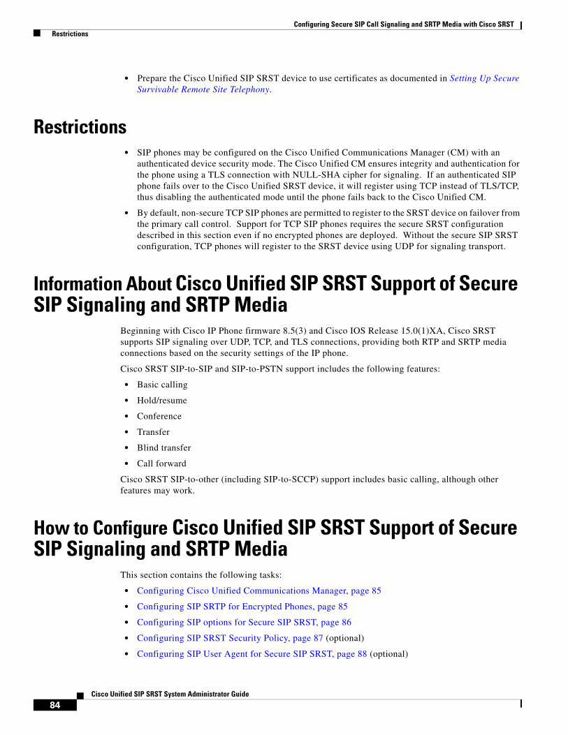
Configuring Secure SIP Call Signaling and SRTP Media with Cisco SRST Restrictions
• Prepare the Cisco Unified SIP SRST device to use certificates as documented in Setting Up Secure Survivable Remote Site Telephony.
Restrictions • SIP phones may be configured on the Cisco Unified Communications Manager (CM) with an
authenticated device security mode. The Cisco Unified CM ensures integrity and authentication for the phone using a TLS connection with NULL-SHA cipher for signaling. If an authenticated SIP phone fails over to the Cisco Unified SRST device, it will register using TCP instead of TLS/TCP, thus disabling the authenticated mode until the phone fails back to the Cisco Unified CM.
• By default, non-secure TCP SIP phones are permitted to register to the SRST device on failover from the primary call control. Support for TCP SIP phones requires the secure SRST configuration described in this section even if no encrypted phones are deployed. Without the secure SIP SRST configuration, TCP phones will register to the SRST device using UDP for signaling transport.
Information About Cisco Unified SIP SRST Support of Secure SIP Signaling and SRTP Media
Beginning with Cisco IP Phone firmware 8.5(3) and Cisco IOS Release 15.0(1)XA, Cisco SRST supports SIP signaling over UDP, TCP, and TLS connections, providing both RTP and SRTP media connections based on the security settings of the IP phone.
Cisco SRST SIP-to-SIP and SIP-to-PSTN support includes the following features:
• Basic calling
• Hold/resume
• Conference
• Transfer
• Blind transfer
• Call forward
Cisco SRST SIP-to-other (including SIP-to-SCCP) support includes basic calling, although other features may work.
How to Configure Cisco Unified SIP SRST Support of Secure SIP Signaling and SRTP Media
This section contains the following tasks:
• Configuring Cisco Unified Communications Manager, page 85
• Configuring SIP SRTP for Encrypted Phones, page 85
• Configuring SIP options for Secure SIP SRST, page 86
• Configuring SIP SRST Security Policy, page 87 (optional)
• Configuring SIP User Agent for Secure SIP SRST, page 88 (optional)
84Cisco Unified SIP SRST System Administrator Guide

Configuring Secure SIP Call Signaling and SRTP Media with Cisco SRST How to Configure Cisco Unified SIP SRST Support of Secure SIP Signaling and SRTP Media
Configuring Cisco Unified Communications ManagerLike SCCP-controlled devices, SIP-controlled devices will use the SRST Reference profile that is listed in their assigned Device Pool. The SRST Reference profile must have the "Is SRST Secure" checkbox selected if SIP/TLS communication is desired in the event of a WAN failure.
Note All Cisco Unified IP Phones must have their firmware updated to version 8.5(3) or later. Devices with firmware earlier than 8.5(3) will need to have a separate Device Pool and SRST Reference profile created without the "Is SRST Secure" option selected; SIP-controlled devices in this Device Pool will use SIP over UDP to attempt to register to the SRST router.
In Cisco Unified Communications Manager Administration, under System > SRST:
• For the secure SRST profile, Is SRST Secure? must be checked. The SIP port must be 5061.
• For the non-secure SRST profile, the Is SRST Secure? checkbox should NOT be checked and the SIP port should be 5060.
Under Device > Phone:
• Secure phones must belong to the pool that uses the secure SRST profile.
• Non-secure phones must belong to the pool that uses the non-secure SRST profile.
Note SIP phones will use the transport method assigned to them by their Phone Security Profile.
Configuring SIP SRTP for Encrypted PhonesThis section specifies that SRTP should be used to enable secure calls and allows non-secure calls to "fallback" to using RTP media.
SUMMARY STEPS
1. enable
2. configure terminal
3. voice service voip
4. srtp fallback
5. allow-connections sip to h323
6. allow-connections sip to sip
7. end
85 Cisco Unified SIP SRST System Administrator Guide
OL-13143-03

Configuring Secure SIP Call Signaling and SRTP Media with Cisco SRST How to Configure Cisco Unified SIP SRST Support of Secure SIP Signaling and SRTP Media
DETAILED STEPS
Configuring SIP options for Secure SIP SRSTThis section explains how to configure secure SIP SRTP.
SUMMARY STEPS
1. enable
2. configure terminal
3. voice service voip
4. sip
5. url sip | sips
Command or Action Purpose
Step 1 enable
Example:Router> enable
Enables privileged EXEC mode.
• Enter your password if prompted.
Step 2 configure terminal
Example:Router# configure terminal
Enters global configuration mode.
Step 3 voice service voip
Example::Router(config)# voice service voip
Enters voice service configuration mode.
Step 4 srtp fallback
Example::Router(config-voi-serv)# srtp fallback
Specifies that SRTP be used to enable secure calls and call fallback.
Step 5 allow-connections sip to h323
Example:Router(config-voi-serv)# allow-connections sip to h323
(Optional) Allows connections from SIP endpoints to H.323 endpoints.
Step 6 allow-connections sip to sip
Example:Router(config-voi-serv)# allow-connections sip to sip
Allows connections from SIP endpoints to SIP endpoints.
Step 7 end
Example:Router(conf-voi-serv)# end
Ends the current configuration session and returns to privileged EXEC mode.
86Cisco Unified SIP SRST System Administrator Guide
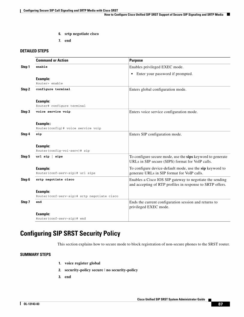
Configuring Secure SIP Call Signaling and SRTP Media with Cisco SRST How to Configure Cisco Unified SIP SRST Support of Secure SIP Signaling and SRTP Media
6. srtp negotiate cisco
7. end
DETAILED STEPS
Configuring SIP SRST Security PolicyThis section explains how to secure mode to block registration of non-secure phones to the SRST router.
SUMMARY STEPS
1. voice register global
2. security-policy secure | no security-policy
3. end
Command or Action Purpose
Step 1 enable
Example:Router> enable
Enables privileged EXEC mode.
• Enter your password if prompted.
Step 2 configure terminal
Example:Router# configure terminal
Enters global configuration mode.
Step 3 voice service voip
Example::Router(config)# voice service voip
Enters voice service configuration mode.
Step 4 sip
Example:Router(config-voi-serv)# sip
Enters SIP configuration mode.
Step 5 url sip | sips
Example:Router(conf-serv-sip)# url sips
To configure secure mode, use the sips keyword to generate URLs in SIP secure (SIPS) format for VoIP calls.
To configure device-default mode, use the sip keyword to generate URLs in SIP format for VoIP calls.
Step 6 srtp negotiate cisco
Example:Router(conf-serv-sip)# srtp negotiate cisco
Enables a Cisco IOS SIP gateway to negotiate the sending and accepting of RTP profiles in response to SRTP offers.
Step 7 end
Example:Router(conf-serv-sip)# end
Ends the current configuration session and returns to privileged EXEC mode.
87 Cisco Unified SIP SRST System Administrator Guide
OL-13143-03

Configuring Secure SIP Call Signaling and SRTP Media with Cisco SRST How to Configure Cisco Unified SIP SRST Support of Secure SIP Signaling and SRTP Media
DETAILED STEPS
Configuring SIP User Agent for Secure SIP SRSTThis section explains how the strict-cipher limits the allowed encryption algorithms.
SUMMARY STEPS
1. sip-ua
2. registrar ipv4:destination-address expires seconds
3. xfer target dial-peer
4. crypto signaling default trustpoint string [strict-cipher]
5. end
Command or Action Purpose
Step 1 voice register global
Example:Router(config)# voice register global
Enters voice register global configuration mode.
Step 2 security-policy secure
Example:Router(config-register-global)# security-policy secure
Configures SIP registration security policy so that only SIP/TLS/TCP connections are allowed.
For device-default mode, use the no security-policy command.
Device-default mode allows non-secure devices to register without using TLS.
Step 3 end
Example:Router(config-register-global)# end
Ends the current configuration session and returns to privileged EXEC mode.
88Cisco Unified SIP SRST System Administrator Guide

Configuring Secure SIP Call Signaling and SRTP Media with Cisco SRST Verifying the Configuration
DETAILED STEPS
Verifying the ConfigurationThe following examples show a sample configuration displayed by the show sip-ua status registrar command and the show voice register global command.
The show sip-ua status registrar command in privileged EXEC mode displays all SIP endpoints that are currently registered with the contact address:
Router# show sip-ua status registrarLine destination expires(sec) contacttransport call-id peer ============ =============== ============ =============== 3029991 192.0.2.108 388 192.0.2.108 TLS [email protected] 40004 3029993 192.0.2.103 382 192.0.2.103 TCP [email protected]
Command or Action Purpose
Step 1 sip-ua
Example:Router(config)# sip-ua
Enters SIP user-agent configuration mode.
Step 2 registrar ipv4:destination-address expires seconds
Example:Router(config-sip-ua)# registrar ipv4:192.0.2.10 expires 3600
Enables the gateway to register E.164 telephone numbers with primary and secondary external SIP registrars. destination-address is the IP address of the primary SIP registrar server.
Step 3 xfer target dial-peer
Example:Router(config-sip-ua)# refer target dial-peer
Specifies that SRST should use the dial-peer as a transfer target instead of what is in the message body.
Step 4 crypto signaling default trustpoint string [strict-cipher]
Example:Router(config-sip-ua)# crypto signaling default trustpoint 3745-SRST strict-cipher
Identifies the trustpoint string keyword and argument used during the TLS handshake. The trustpoint string keyword and argument refer to the gateway’s certificate generated as part of the enrollment process, using Cisco IOS public-key infrastructure (PKI) commands. The strict-cipher keyword restricts support to TLS RSA encryption with the Advanced Encryption Standard-128 (AES-128) cipher-block-chaining (CBC) Secure Hash Algorithm (SHA) (TLS_RSA_WITH_AES_128_CBC_SHA) cipher suite.
To configure device-default mode, omit the strict-cipher keyword.
Step 5 end
Example:Router(config-sip-ua)# end
Ends the current configuration session and returns to privileged EXEC mode.
89 Cisco Unified SIP SRST System Administrator Guide
OL-13143-03
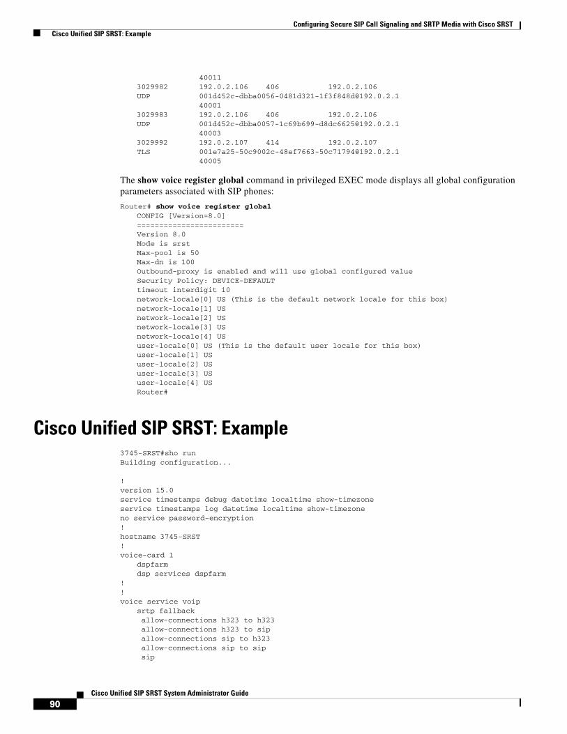
Configuring Secure SIP Call Signaling and SRTP Media with Cisco SRST Cisco Unified SIP SRST: Example
40011 3029982 192.0.2.106 406 192.0.2.106 UDP [email protected] 40001 3029983 192.0.2.106 406 192.0.2.106 UDP [email protected] 40003 3029992 192.0.2.107 414 192.0.2.107 TLS [email protected] 40005
The show voice register global command in privileged EXEC mode displays all global configuration parameters associated with SIP phones:
Router# show voice register global CONFIG [Version=8.0] ======================== Version 8.0Mode is srst Max-pool is 50 Max-dn is 100 Outbound-proxy is enabled and will use global configured value Security Policy: DEVICE-DEFAULT timeout interdigit 10 network-locale[0] US (This is the default network locale for this box) network-locale[1] US network-locale[2] US network-locale[3] US network-locale[4] US user-locale[0] US (This is the default user locale for this box) user-locale[1] US user-locale[2] US user-locale[3] US user-locale[4] US Router#
Cisco Unified SIP SRST: Example3745-SRST#sho runBuilding configuration...
!version 15.0service timestamps debug datetime localtime show-timezoneservice timestamps log datetime localtime show-timezoneno service password-encryption!hostname 3745-SRST!voice-card 1
dspfarmdsp services dspfarm
!!voice service voip
srtp fallback allow-connections h323 to h323 allow-connections h323 to sip allow-connections sip to h323 allow-connections sip to sip sip
90Cisco Unified SIP SRST System Administrator Guide

Configuring Secure SIP Call Signaling and SRTP Media with Cisco SRST Cisco Unified SIP SRST: Example
bind control source-interface FastEthernet0/0 bind media source-interface FastEthernet0/0 session transport tcp tls registrar server expires max 600 min 60 srtp negotiate cisco
!voice register global
system message Welcome to SIP SRST Secure Fallback max-dn 100 max-pool 50
!voice register pool 1
id network 10.2.0.0 mask 255.255.0.0 codec g711ulaw
!!!crypto pki trustpoint cl-b-pub
enrollment terminal revocation-check none
!crypto pki trustpoint 3745-SRST
enrollment selfsigned fqdn none subject-name CN=3745-SRST revocation-check none rsakeypair 3745-SRST
!crypto pki trustpoint CAP-RTP-001
enrollment terminal revocation-check none
!crypto pki trustpoint CAP-RTP-002
enrollment terminal revocation-check none
!crypto pki trustpoint Cisco_Root_CA_2048
enrollment terminal revocation-check none
!crypto pki trustpoint Cisco_Manufacturing_CA
enrollment terminal revocation-check none
!!!interface FastEthernet0/0
description "Remote Site" LAN ip address 10.2.30.1 255.255.255.0 duplex auto speed auto !
!interface FastEthernet0/1
description "WAN" connection to Cluster-B ip address 10.2.0.6 255.255.255.0 duplex auto speed auto
!!sip-ua
registrar ipv4:10.2.0.10 expires 3600 xfer target dial-peer crypto signaling default trustpoint 3745-SRST
91 Cisco Unified SIP SRST System Administrator Guide
OL-13143-03

Configuring Secure SIP Call Signaling and SRTP Media with Cisco SRST Cisco Unified SIP SRST: Example
!!credentials
ip source-address 10.2.30.1 port 2445 trustpoint 3745-SRST
!!call-manager-fallback
max-conferences 8 gain -6 transfer-system full-consult ip source-address 101.2.30.1 port 2000 max-ephones 10 max-dn 20
!line con 0
exec-timeout 0 0line aux 0line vty 0 4
password lab login transport input all
line vty 5 15 password lab login transport input all
!end
3745-SRST#
92Cisco Unified SIP SRST System Administrator Guide

Configuring Secure SIP Call Signaling and SRTP Media with Cisco SRST Additional References
Additional ReferencesThe following sections provide references related to this feature.
Related Documents
Standards
MIBs
RFCs
Related Topic Document Title
Cisco IOS voice configuration • Cisco IOS Voice Configuration Library
• Cisco IOS Voice Command Reference
Cisco Unified SRST configuration • Cisco Unified SIP SRST System Administrator Guide
• Cisco Unified SRST System Administrator Guide
• Cisco Unified SRST and SIP SRST Command Reference
Cisco Unified SRST • Cisco Unified SRST 8.0 Supported Firmware, Platforms, Memory, and Voice Products
Standard Title
No new or modified standards are supported by this feature, and support for existing standards has not been modified by this feature.
—
MIB MIBs Link
No new or modified MIBs are supported by this feature, and support for existing MIBs has not been modified by this feature.
To locate and download MIBs for selected platforms, Cisco IOS releases, and feature sets, use Cisco MIB Locator found at the following URL:
http://www.cisco.com/go/mibs
RFC Title
No new or modified RFCs are supported by this feature, and support for existing RFCs has not been modified by this feature.
—
93 Cisco Unified SIP SRST System Administrator Guide
OL-13143-03
Configuring Secure SIP Call Signaling and SRTP Media with Cisco SRST Command Reference
Technical Assistance
Command ReferenceThe following commands are introduced or modified in the feature or features documented in this section. For information about these commands, see the Cisco IOS Voice Command Reference at http://www.cisco.com/en/US/docs/ios/voice/command/reference/vr_book.html. For information about all Cisco IOS commands, use the Command Lookup Tool at http://tools.cisco.com/Support/CLILookup or the Cisco IOS Master Command List, All Releases, at http://www.cisco.com/en/US/docs/ios/mcl/allreleasemcl/all_book.html.
• security-policy
• show voice register global
• show voice register all
Description Link
The Cisco Support website provides extensive online resources, including documentation and tools for troubleshooting and resolving technical issues with Cisco products and technologies.
To receive security and technical information about your products, you can subscribe to various services, such as the Product Alert Tool (accessed from Field Notices), the Cisco Technical Services Newsletter, and Really Simple Syndication (RSS) Feeds.
Access to most tools on the Cisco Support website requires a Cisco.com user ID and password.
http://www.cisco.com/techsupport
94Cisco Unified SIP SRST System Administrator Guide

Configuring Secure SIP Call Signaling and SRTP Media with Cisco SRST Feature Information for Secure SIP Call Signaling and SRTP Media with Cisco SRST
Feature Information for Secure SIP Call Signaling and SRTP Media with Cisco SRST
Table 7 lists the release history for this feature.
Not all commands may be available in your Cisco IOS software release. For release information about a specific command, see the command reference documentation.
Use Cisco Feature Navigator to find information about platform support and software image support. Cisco Feature Navigator enables you to determine which Cisco IOS and Catalyst OS software images support a specific software release, feature set, or platform. To access Cisco Feature Navigator, go to http://www.cisco.com/go/cfn. An account on Cisco.com is not required.
Note Table 7 lists only the Cisco IOS software release that introduced support for a given feature in a given Cisco IOS software release train. Unless noted otherwise, subsequent releases of that Cisco IOS software release train also support that feature.
Table 7 Feature Information for Secure SIP Call Signaling and SRTP Media with Cisco SRST
Feature Name Releases Feature Information
Secure SIP Call Signaling and SRTP Media with Cisco SRST
15.0(1)XA Adds Session Initiation Protocol/Transport Layer Security/Transmission Control Protocol (SIP/TLS/TCP) support for secure call signaling and Secure Real-time Transport Protocol (SRTP) for media encryption to establish a secure, encrypted connection between Cisco Unified IP Phones and a failover device using Cisco Unified Survivable Remote Site Telephony (Cisco SRST). The following commands were introduced or modified: security-policy, show voice register global, show voice register all
95 Cisco Unified SIP SRST System Administrator Guide
OL-13143-03

Configuring Secure SIP Call Signaling and SRTP Media with Cisco SRST Feature Information for Secure SIP Call Signaling and SRTP Media with Cisco SRST
96Cisco Unified SIP SRST System Administrator Guide

Enhanced 911 Services
Last Updated: July 11, 2008
This chapter describes the Enhanced 911 Services feature.
Finding Feature Information in This Module
Your Cisco Unified SIP SRST version may not support all of the features documented in this module. For a list of the versions in which each feature is supported, see the “Feature Information for Enhanced 911 Services” section on page 134.
Contents • Prerequisites, page 97
• Restrictions, page 98
• Information About Enhanced 911 Services, page 98
• Configuring Enhanced 911 Services, page 109
• Cisco Unified SIP SRST: Examples, page 127
• Feature Information for Enhanced 911 Services, page 134
• Where to Go Next, page 134
Prerequisites • Cisco Unified SIP SRST 4.1 or later versions
• SCCP or SIP phones must be registered to the Cisco Unified SIP SRST server.
• At least one CAMA or ISDN trunk must be configured from Cisco Unified SIP SRST to each of the 911 service provider’s public safety answering point (PSAP).
• An Enhanced 911 network must be designed for each customer’s voice network
• Cisco Unified SIP SRST can use FXS, FXO, SIP, or H.323 trunk interfaces.
97Cisco Unified SIP SRST System Administrator Guide
OL-13143-03

Enhanced 911 ServicesRestrictions
Restrictions • Enhanced 911 Services for Cisco Unified SIP SRST does not interface with the
Cisco Emergency Responder.
• The information about the most recent phone that called 911 is not preserved after a reboot of Cisco Unified SIP SRST.
• For Cisco Unified Wireless 7920 and 7921 IP phones, a caller’s location can only be determined by the static information configured by the system administrator. For more information, see the “Precautions for Mobile Phones” section on page 103.
• The extension numbers of 911 callers can be translated to only two emergency location identification numbers (ELINs) for each emergency response location (ERL). For more information, see the “Overview” section on page 98.
• Using ELINs for multiple purposes can result in unexpected interactions with existing Cisco Unified SIP SRST features. These multiple uses of an ELIN can include configuring an ELIN for use as an actual phone number (ephone-dn, voice register dn, or FXS destination-pattern), a Call Pickup number, or an alias rerouting number. For more information, see the “Multiple Usages of an ELIN” section on page 106.
• Your configuration of Enhanced 911 Services can interact with existing Cisco Unified SIP SRST features and cause unexpected behavior. For a complete description of interactions between Enhanced 911 Services and existing Cisco Unified SIP SRST features, see the “Interactions with Existing Cisco Unified SIP SRST Features” section on page 106.
Information About Enhanced 911 ServicesThis section contains the following information about Enhanced 911 Services:
• Overview, page 98
• Call Processing, page 101
• New Features for Version 4.2(1), page 103
• Precautions for Mobile Phones, page 103
• Planning Your Implementation of Enhanced 911 Services, page 104
• Interactions with Existing Cisco Unified SIP SRST Features, page 106
OverviewEnhanced 911 Services for Cisco Unified SIP SRST enables 911 operators to:
• Immediately pinpoint the location of the 911 caller based on the calling number
• Callback the 911 caller if a disconnect occurs
Before this feature was introduced, Cisco Unified SIP SRST supported only outbound calls to 911. With basic 911 functionality, calls were simply routed to a public safety answering point (PSAP). The 911 operator at the PSAP would then have to verbally gather the emergency information and location from the caller, before dispatching a response team from the ambulance service, fire department, or police department. Calls could not be routed to different PSAPs, based on the specific geographic areas that they cover.
98Cisco Unified SIP SRST System Administrator Guide

Enhanced 911 ServicesInformation About Enhanced 911 Services
With Enhanced 911 Services, 911 calls are selectively routed to the closest PSAP based on the caller’s location. In addition, the caller’s phone number and address automatically display on a terminal at the PSAP. Therefore, the PSAP can quickly dispatch emergency help, even if the caller is unable to communicate the location. Also, if the caller disconnects prematurely, the PSAP has the information it needs to contact the 911 caller.
To use Enhanced 911 Services, you must define an emergency response location (ERL) for each of the geographic areas needed to cover all of the phones supported by Cisco Unified SIP SRST. The geographic specifications for ERLs are determined by local law. For example, you might have to define an ERL for each floor of a building because an ERL must be less than 7000 square feet in area. Because the ERL defines a known, specific location, this information is uploaded to the PSAP’s database and is used by the 911 dispatcher to help the emergency response team to quickly locate a caller.
To determine which ERL is assigned to a 911 caller, the PSAP uses the caller’s unique phone number, which is also known as the emergency location identification number (ELIN). Before you can use Enhanced 911 Services you must supply the PSAP with a list of your ELINs and street addresses for each ERL. This information is saved in the PSAP’s automatic location identification (ALI) database. Typically, you give this information to the PSAP when your phone system is installed.
With the address information in the ALI database, the PSAP can find the caller’s location and can also use the ELIN to callback the 911 caller within a specified time limit. This limit applies to the Last Caller table, which provides the PSAP with the 911 caller’s ELIN. If no time limit is specified for the Last Caller table, the default expiry time is three hours.
In addition to saving call formation in the temporary Last Caller table, you can configure permanent call detail records. You can view the attributes in these records from RADIUS accounting, the syslog service, or CLI show commands.
You have the option of configuring zero, one, or two ELINs for each ERL. If you configure two ELINs, the system uses a round-robin algorithm to select which ELIN is sent to the PSAP. If you do not define an ELIN for an ERL, the PSAP sees the original calling number. You may not want to define an ELIN if Cisco Unified SIP SRST is using direct-inward-dial numbers or the call is from another Cisco voice gateway that has already translated the extension to an ELIN.
Optionally define a default ELIN that the PSAP can use if a 911 caller's IP phone's address does not match the IP subnet of any location in any zone. This default ELIN can be an existing ELIN that is already defined for one of the ERLs or it can be a unique ELIN. If no default ELIN is defined and the 911 caller’s IP Address does not match any of the ERLs’ IP subnets, a syslog message is issued stating that no default ELIN is defined, and the original ANI remains intact.
You can also define a designated callback number that is used when the callback information is lost in the Last Caller table because of an expiry timeout or system restart or when the PSAP cannot reach the 911 caller at the caller’s ELIN or the default ELIN for any other reason.
You can further customize your system by specifying the expiry time for data in the Last Caller table and by enabling syslog messages that announce all emergency calls
For large installations, you can optionally specify that calls from specific ERLs are routed to specific PSAPs. This is done by configuring emergency response zones, which lists the ERLs within each zone. This list of ERLs also includes a ranking of the locations which controls the order of ERL searches when there are multiple PSAPs. You do not need to configure emergency response zones if all 911 calls on your system are routed to a single PSAP.
One or more ERLs can be grouped into a zone which could be equivalent to the area serviced by a PSAP. When an outbound emergency call is placed, configured emergency response zones allow the searching of a subset of the ERLs in any order. The ERLs can be ranked in the order of desired usage.
99Cisco Unified SIP SRST System Administrator Guide

Enhanced 911 ServicesInformation About Enhanced 911 Services
Zones are also used to selectively route 911 calls to different PSAPs.You can configure selective routing by creating a zone with a list of unique locations and assigning each zone to a different outbound dial peer. In this case, zones route the call based on the caller’s ERL. When an emergency call is made, each dial peer matching the called number uses the zone’s list of locations to find a matching IP subnet to the calling phone’s IP address. If an ERL and ELIN are found, the dial peer’s interface is used to route the call. If no ERL or ELIN is found, the next matched dial peer checks its zone.
Note If a caller’s IP address does not match any location in its dial peer’s zone, the last dial peer that matched is used for routing and the default ELIN is used. If you want 911 calls from any particular phone to always use the same dial peer when you have multiple dial peers going to the same destination-pattern (911) and the zones are different, you must configure the preferred dial peer to be the highest priority by setting the preference field.
Duplicate location tags are not allowed in the same zone. However, the same location tag can be defined in multiple zones. You are allowed to enter duplicate location priorities in the same zone, however, the existing location’s priority is then increased to the next number. For example, if you configure “location 36 priority 5” followed by “location 19 priority 5,” location 19 has priority 5 and location 36 becomes priority 6. Also, if two locations are assigned priority 100, rather than bump the first location to priority 101, the first location becomes the first nonprioritized location.
Figure 5 shows a an example configuration for 911 services. In this example, the phone system handles calls from multiple floors in multiple buildings. Five ERLs are defined, with one ELIN defined for each ERL. At the PSAP, the ELIN is used to find the caller’s physical address from the ALI database. In this example, building 2 is closer to the PSAP in San Francisco and Building 40 is closer to the PSAP in San Jose. Therefore, in this case, we recommend that you configure two emergency response zones to ensure that 911 calls are routed to the PSAP closest to the caller. In this example, you can configure an emergency response zone that includes all of the ERLS in building 2 and another zone that includes the ERLs in building 40. If you choose to not configure emergency response zones, 911 calls will be routed based on matching with the destination number configured for the outgoing dial peers.
Figure 5 Implementation of Enhanced 911
ext. 44
ext. 2223
0079
ERL 1: ELIN 408 555 0102
ERL 2: ELIN 408 555 0101
ERL 3: ELIN 408 555 0100
Building 2
Building 40
ERL 5: ELIN 408 555 0160
ERL 4: ELIN 408 555 0161
Serviceprovider’snetwork
Serviceprovider’snetwork
San FranciscoPSAP
San JosePSAP 408 555 0161
801 Main Street,Floor 1, San Jose
ELIN
CAMA
CAMA
ALI
100Cisco Unified SIP SRST System Administrator Guide

Enhanced 911 ServicesInformation About Enhanced 911 Services
Call ProcessingWhen a 911 call is received by Cisco Unified SIP SRST, the initial call processing is the same as for any other call. Cisco Unified SIP SRST takes the called-number and searches for dial peers that can be used to route the call to that called-number.
The Enhanced 911 feature also analyzes the outgoing dial peer to see if it is going to a PSAP. If the outgoing dial peer is configured with the emergency response zone command, the system is notified that the call needs Enhanced 911 handling. If the outgoing dial peer is not configured with the emergency response zone command, the Enhanced 911 functionality is not activated and the caller’s number is not translated to an ELIN.
When the Enhanced 911 functionality is activated, the first step in Enhanced 911 handling is to determine which ERL is assigned to the caller. There are two ways to determine the caller’s ERL.
• Explicit Assignment — If a 911 call arrives on an inbound dial peer that has an ERL assignment, this ERL is automatically used as the caller’s location.
• Implicit Assignment — If a 911 call arrives from an IP phone, its IP address is determined and Enhanced 911 searches for the IP address of the caller’s phone in one of the IP subnets configured in the ERLs. The ERLs are stored as an ordered list according to their tag numbers, and each subnet is compared to the caller’s IP address in the order listed.
After the caller’s ERL is determined, the caller’s number is translated to that ERL’s ELIN. If no ERLs are implicitly or explicitly assigned to a particular call, you can define a default ERL for IP phones. This default ERL does not apply to nonIP-phone endpoints, such as phones on VoIP trunks or FXS/FXO trunks.
After an ELIN is determined for the call, the following information is saved to the Last Caller table:
• Caller’s ELIN
• Caller’s original extension
• Time the call originated
The Last Caller table contains this information for the most recent emergency callers from each ERL. A caller’s information is purged from the table when the specified expiry time has passed after the call was originated. If no time limit is specified, the default expiry time is three hours.
After the 911 call information is saved to the Last Caller table, the system determines whether an emergency response zone is configured that contains the caller’s ERL. If no emergency response zone is configured with the ERL, all ERLs are searched sequentially to match the caller’s IP address and then route the 911 call to the appropriate PSAP. If an ERL is included in a zone, the 911 call is routed to the PSAP associated with that zone.
After the 911 call is routed to appropriate PSAP, Enhanced 911 processing is complete. Call processing then proceeds as it does for basic calls, except that the ELIN replaces the original calling number for the outbound setup request.
Figure 6 summarizes the procedure for processing a 911 call.
101Cisco Unified SIP SRST System Administrator Guide

Enhanced 911 ServicesInformation About Enhanced 911 Services
Figure 6 Processing a 911 Call
The 911 operator is unable to find information about a call in the Last Caller table if the router was rebooted or specified expiry time (three hours by default) has passed after the call was originated. If this is the case, the 911 operator hears the reorder tone. To prevent the 911 operator from getting this tone, you can configure the default callback as described in the “Configuring Outgoing Dial Peers for Enhanced 911 Services” section on page 112. Alternately, you can configure a call forward number on the dial peer that goes to an operator or primary contact at the business.
Extension 1100 calls 911
The called-number (911)is used to match dial-peer(s).
Does the PSAP'sdial-peer have the
emergency responsetag configured?
Is an ERL found from either the: 1) Inbound dial-peer configuration 2) Phone’s IP address
Does ERL have anELIN configured?
Replace callingnumber 1100with ELIN.
Calling number remains intact.
911 call information is saved in a table for PSAP to use for callback.
Call setup request continues as usual.
No
No
No
Yes
Yes
Yes23
0228
102Cisco Unified SIP SRST System Administrator Guide
Enhanced 911 ServicesInformation About Enhanced 911 Services
Because the 911 callback feature tracks the last caller by its extension number, if you change the configuration of your ephone-dns in-between a 911 call and a 911 callback and within the expiry time, the PSAP might not be able to successfully contact the last 911 caller.
If two 911 calls are made from different phones in the same ERL within a short period of time, the first caller’s information is overwritten in the Last Caller table with the information for the second caller. Because the table can contain information about only one caller from each ERL, the 911 operator does not have the information needed to contact the first caller.
In most cases, if Cisco Emergency Responder is configured, you should configure Enhanced 911 Services with the same data for the ELIN and ERL as used by Cisco Emergency Responder.
New Features for Version 4.2(1)Version 4.2(1) of Enhanced 911 Services includes these new features:
• Assigning ERLs to zones to enable routing to the PSAP that is closest to the caller
• Customizing E911 by defining a default ELIN, identifying a designated number if the 911 caller cannot be reached on callback, specifying the expiry time for data in the Last Caller table, and enabling syslog messages that announce all emergency calls
• Expanding the E911 location information to include name and address
• Adding new permanent call detail records
• Adding new troubleshooting commands
Precautions for Mobile PhonesEmergency calls placed from phones that have been removed from their primary site might not be answered by local safety authorities. Do not use IP phones to place emergency calls if removed from the site where it was initially configured. Therefore, we recommend that you require your mobile phone users to agree to a policy similar to the one stated below.
Telecommuters, remote office, and traveling personnel must place emergency calls on a locally configured hotel, office, or home phone landline. If they must use a remote IP phone for emergency calls while away from their configured site, they must be prepared to provide specific information regarding their location (their country, city, state, street address, and so on) to the answering safety authority or security operations center personnel.
By accepting this policy your mobile phone users are confirming that they:
• Understand this advisory
• Agree to take reasonable precautions to prevent use of any remote IP phone device for emergency calls when it is removed from its configured site
By not responding to or declining to accept this policy, your mobile phone users are confirming that they understand that all remote IP phone devices associated with them will be disconnected, and no future requests for these services will be fulfilled.
103Cisco Unified SIP SRST System Administrator Guide
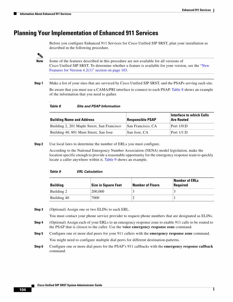
Enhanced 911 ServicesInformation About Enhanced 911 Services
Planning Your Implementation of Enhanced 911 ServicesBefore you configure Enhanced 911 Services for Cisco Unified SIP SRST, plan your installation as described in the following procedure.
Note Some of the features described in this procedure are not available for all versions of Cisco Unified SIP SRST. To determine whether a feature is available for your version, see the “New Features for Version 4.2(1)” section on page 103.
Step 1 Make a list of your sites that are serviced by Cisco Unified SIP SRST, and the PSAPs serving each site.
Be aware that you must use a CAMA/PRI interface to connect to each PSAP. Table 8 shows an example of the information that you need to gather.
.
Step 2 Use local laws to determine the number of ERLs you must configure.
According to the National Emergency Number Association (NENA) model legislation, make the location specific enough to provide a reasonable opportunity for the emergency response team to quickly locate a caller anywhere within it. Table 9 shows an example.
Step 3 (Optional) Assign one or two ELINs to each ERL.
You must contact your phone service provider to request phone numbers that are designated as ELINs.
Step 4 (Optional) Assign each of your ERLs to an emergency response zone to enable 911 calls to be routed to the PSAP that is closest to the caller. Use the voice emergency response zone command.
Step 5 Configure one or more dial peers for your 911 callers with the emergency response zone command.
You might need to configure multiple dial peers for different destination-patterns.
Step 6 Configure one or more dial peers for the PSAP’s 911 callbacks with the emergency response callback command.
Table 8 Site and PSAP Information
Building Name and Address Responsible PSAPInterface to which Calls Are Routed
Building 2, 201 Maple Street, San Francisco San Francisco, CA Port 1/0:D
Building 40, 801 Main Street, San Jose San Jose, CA Port 1/1:D
Table 9 ERL Calculation
Building Size in Square Feet Number of FloorsNumber of ERLs Required
Building 2 200,000 3 3
Building 40 7000 2 1
104Cisco Unified SIP SRST System Administrator Guide

Enhanced 911 ServicesInformation About Enhanced 911 Services
Step 7 Decide what method to use to assign the phones to each ERL.
You have the following choices:
• For a group of phones that are on the same subnet, you can create an IP subnet in the ERL that includes each phone’s IP address. Each ERL can have one or two unique IP subnets. This is the easiest option to configure. Table 10 shows an example.
• You can assign an ERL explicitly to a group of phones by using the ephone-template and voice register template configurations. Instead of assigning an ERL to phones individually, you can use these templates to save time if you want to apply the same set of features to several ephones or SIP phones.
• You can assign an ERL to a phone individually. Depending on which type of phone you have, you can use one of three methods. You can assign an ERL to a phone’s:
– Ephone configuration
– Dial-peer configuration
– Voice register pool configuration
Table 11 shows examples of each of these options.
Step 8 (Optional) Define a default ELIN to be sent to the PSAP for use if a 911 caller's IP phone's address does not match the IP subnet of any location in any zone.
Step 9 (Optional) Define a designated callback number that is used if the callback information is removed from the Last Caller table because of an expiry timeout or system restart.
Step 10 (Optional) Change the expiry time for data in the Last Caller table from the default time of three hours.
Step 11 (Optional) Enable RADIUS accounting or the syslog service to permanently record call detail records.
Table 10 Example Settings for ERLs, Descriptions, IP Subnet Addresses, and ELINs
ERL Number Description IP Address Assignment ELIN
1 Building 2, 1st floor 10.5.124.xxx 408 555-0142
2 Building 2, 2nd floor 10.7.xxx.xxx 408 555-0143
3 & 4 Building 2, 3rd floor 10.8.xxx.xxx and 10.9.xxx.xxx
408 555-0144 and 408 555-0145
Table 11 Explicit ERL Assignment Per Phone
Phone Configuration ERL
Ephone 100 3
Dial-peer voice 213 pots 3
Dial-peer voice 214 voip 4
Voice register pool 1 2
105Cisco Unified SIP SRST System Administrator Guide
Enhanced 911 ServicesInformation About Enhanced 911 Services
Interactions with Existing Cisco Unified SIP SRST FeaturesEnhanced 911 Services interacts with several existing Cisco Unified SIP SRST features. The interactions with each of the following features are described in separate sections below:
Note Your version of Cisco Unified SIP SRST might not support all of these features.
• Multiple Usages of an ELIN, page 106
• Number Translation, page 106
• Call Transfer, page 107
• Call Forward, page 107
• Call Blocking Features, page 107
• Call Waiting, page 107
• Three-Way Conference, page 108
• Dial-Peer Rotary, page 108
• Dial Plan Patterns, page 108
• Caller ID Blocking, page 108
Multiple Usages of an ELIN
Caution We recommend that you do not use ELINs for any other purpose because of possible unexpected interactions with existing Cisco Unified SIP SRST features.
Examples of using ELINs for other purposes include configuring an ELIN for use as an actual phone number (ephone-dn, voice register dn, FXS destination-pattern), a Call Pickup number, or an alias rerouting number.
Using ELINs as an actual phone number causes problems when calls are made to that number. If a 911 call occurs and the last caller information has not expired from the Last Caller table, any outside callers will reach the last 911 caller instead of the actual phone. We recommend that you do not share the phone numbers used for ELINs with real phones.
There is no impact on outbound 911 calls if you use the same number for an ELIN and a real phone number.
Number Translation
The Enhanced 911 feature translates the calling number to an ELIN during an outbound 911 call, and translates the called-number to the last caller’s extension during a 911 callback (when the PSAP makes a callback to the 911 caller). Alternative methods of number translation can conflict with the translation done by the Enhanced 911 software, such as:
• Dialplan-pattern — Prefixes a pattern to an extension configured under telephony-service
• Num-exp — Expands extensions to full E.164 numbers
• Voice-port translation of called and calling numbers
106Cisco Unified SIP SRST System Administrator Guide
Enhanced 911 ServicesInformation About Enhanced 911 Services
• Outgoing number translation for dial peers
• Translate-profile for dial peers
• Voice translation profiles done for the dial peer, voice-port, POTS voice service, trunk group, trunk group member, voice source-group, call-manager-fallback, and ephone-dn
• Ephone-dn translation
• Voice register dn’s outgoing translation
Configuring these translation features impacts the Enhanced 911 feature if they translate patterns that are part of your ELINs’ patterns. For an outgoing 911 call, these features might translate an Enhanced 911 ELIN to a different number, giving the PSAP a number they cannot look-up in their ALI databases. If the 911 callback number (ELIN) is translated before Enhanced 911 callback processing, the Enhanced 911 feature is unable to find the last caller’s history.
Call Transfer
If a phone in a Cisco Unified SIP SRST environment performs a semiattended or consultative transfer to the PSAP that involves another phone that is in a different ERL, the PSAP will use the wrong ELIN. The PSAP will see the ELIN of the transferor party, not the transferred party.
There is no impact on 911 callbacks (calls made by the PSAP back to a 911 caller) or transfers that are made by the PSAP.
A 911 caller can transfer the PSAP to another party if there is a valid reason to do so. Otherwise, we recommend that the 911 caller remain connected to the PSAP at all times.
Call Forward
There is no impact if an IP phone user calls another phone that is configured to forward calls to the PSAP.
If the PSAP makes a callback to a 911 caller that is using a phone that has Call Forward enabled, the PSAP is redirected to a party that is not the original 911 caller.
Call Blocking Features
Outbound 911 calls can be blocked by features such as After-Hours Call Blocking if the system administrator does not create an exception to 911 calls.
911 callbacks will not reach the 911 caller if the phone is configured with a blocking feature (for example, Do Not Disturb).
Call Waiting
After a 911 call is established with a PSAP, call waiting can interrupt the call. The 911 caller has the choice of putting the operator on hold. Although holding is not prohibited, we recommend that the 911 caller remain connected to the PSAP until the call is over.
107Cisco Unified SIP SRST System Administrator Guide

Enhanced 911 ServicesInformation About Enhanced 911 Services
Three-Way Conference
Although the 911 caller is allowed to activate three-way conferencing when talking to the PSAP, we recommend that the 911 caller remain connected privately to the PSAP until the call is over.
Dial-Peer Rotary
If a 911 caller uses a rotary phone, you must configure each dial peer with the emergency response zone command for the call to be processed as an Enhanced 911 call. Otherwise, calls received on dial peers that are not configured for Enhanced 911 functionality are treated as regular calls and there is no ELIN translation.
Do not configure two dial peers with the same destination-pattern to route to different PSAPs. The caller’s number will not be translated to two different ELINs and the two dial peers will not route to different PSAPs. However, you can route calls to different PSAPs if you configure the dial peers with different destination-patterns (for example, 9911 and 95105558911). You might need to use the number translation feature or add prefix/forward-digits to change the 95105558911 to 9911 for the second dial peer if a specific called-number is required by the service provider.
Tip We recommend that you do not configure the same dial peer using both the emergency response zone and emergency response callback commands.
Dial Plan Patterns
Dial plan patterns expand the caller’s original extension number into a fully qualified E.164 number. If an ERL is found for a 911 caller, the expanded number is translated to an ELIN.
For 911 callbacks, the called-number is translated to the 911 caller’s expanded number.
Caller ID Blocking
When you set Caller ID Blocking for an ephone or voice-port configuration, the far-end gateway device blocks the display of the calling party information. This feature is overridden when an Enhanced 911 call is placed because the PSAP must receive the ELIN (the calling party information).
The Caller ID Blocking feature does not impact callbacks.
108Cisco Unified SIP SRST System Administrator Guide

Enhanced 911 ServicesConfiguring Enhanced 911 Services
Configuring Enhanced 911 ServicesThis section contains the following:
• Configuring the Emergency Response Location, page 109 (required)
• Configuring Locations under Emergency Response Zones, page 111 (optional)
• Configuring Outgoing Dial Peers for Enhanced 911 Services, page 112 (required)
• Configuring a Dial Peer for Callbacks from the PSAP, page 116 (required)
• Assigning ERLs to Phones, page 117 (required)
• Configuring Customized Settings, page 121 (optional)
• Using the Address Command for Two ELINS, page 123 (optional)
• Enabling Call Detail Records, page 123 (optional)
• Verifying E911 Configuration, page 125 (optional)
Configuring the Emergency Response LocationThe ERL can define zero, one, or two ELINs. If one ELIN is defined, this ELIN is always used for phones calling from this ERL. If you define two ELINs, the system alternates using each ELIN for phones calling from this ERL. If you define no ELINs and phones use this ERL, the outbound calls do not have their calling numbers translated. The PSAP sees the original calling numbers for these 911 calls.
If multiple ERLs are created, the Enhanced 911 software uses the ERL tag number to determine which ELIN to use. The Enhanced 911 software searches the ERLs sequentially from tag 1 to 2147483647. The first ERL that has a subnet mask encompassing the caller's IP address is used for ELIN translation.
Note The voice emergency response location command is expanded to include two new optional ERL fields, name and address. The name field provides a word or description of the ERL for administrative purposes. For example, name Bldg 20 3rd floor describes the purpose of an ERL configuration. The address field is a comma separated text entry of the ERL’s civic address. The address is saved as part of the E911 ERL configuration. When used with the show voice emergency addresses command, the address information can be saved to a text file.
Prerequisites
• Plan your 911 configuration as described in “Planning Your Implementation of Enhanced 911 Services” section on page 104.
• Cisco Unified SIP SRST Version 4.2(1) or Version 4.1 must be installed
• See the prerequisites described in the “Prerequisites” section on page 97
Restrictions
The name and address fields are not available for Cisco Unified SIP SRST Version 4.1.
109Cisco Unified SIP SRST System Administrator Guide

Enhanced 911 ServicesConfiguring Enhanced 911 Services
SUMMARY STEPS
1. enable
2. configure terminal
3. voice emergency response location tag
4. elin [1 | 2] E.164 number
5. address address
6. name name
7. end
DETAILED STEPS
Command or Action Purpose
Step 1 enable
Example:Router> enable
Enables privileged EXEC mode.
• Enter your password if prompted.
Step 2 configure terminal
Example:Router# configure terminal
Enters global configuration mode.
Step 3 voice emergency response location tag
Example:Router(config)# voice emergency response loca-tion 4
Enters emergency response location configuration mode to define parameters for an ERL.
Step 4 elin [1 | 2] E.164 number
Example:Router(cfg-emrgncy-resp-location)# elin 1 4085550100
(Optional) Specifies the ELIN, an E.164 PSTN number that replaces the caller's extension. This number is displayed on the PSAP’s terminal and is used by the PSAP to query the ALI database to locate the caller. It is also used by the PSAP for callbacks. You can define a second ELIN using the optional elin 2 command. If an ELIN is not defined for the ERL, the PSAP sees the original calling number.
Step 5 address address
Example:Router(cfg-emrgncy-resp-location)# address I,604,5550100, ,184 ,Main St,Kansas City,KS,1,
(Optional) Defines a string used for the automatic location identification (ALI) database upload of the caller’s address. The string must conform to the record format that is required by the service provider. The string maximum is 247 characters.
110Cisco Unified SIP SRST System Administrator Guide
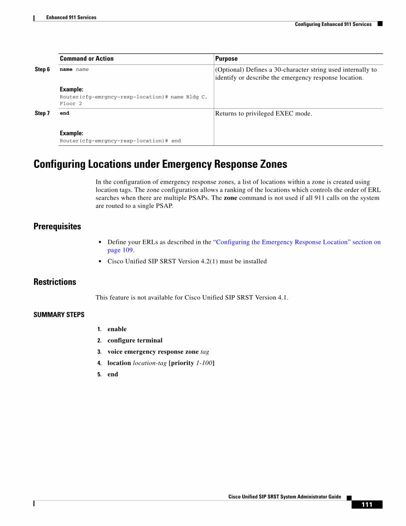
Enhanced 911 ServicesConfiguring Enhanced 911 Services
Configuring Locations under Emergency Response ZonesIn the configuration of emergency response zones, a list of locations within a zone is created using location tags. The zone configuration allows a ranking of the locations which controls the order of ERL searches when there are multiple PSAPs. The zone command is not used if all 911 calls on the system are routed to a single PSAP.
Prerequisites
• Define your ERLs as described in the “Configuring the Emergency Response Location” section on page 109.
• Cisco Unified SIP SRST Version 4.2(1) must be installed
Restrictions
This feature is not available for Cisco Unified SIP SRST Version 4.1.
SUMMARY STEPS
1. enable
2. configure terminal
3. voice emergency response zone tag
4. location location-tag [priority 1-100]
5. end
Step 6 name name
Example:Router(cfg-emrgncy-resp-location)# name Bldg C, Floor 2
(Optional) Defines a 30-character string used internally to identify or describe the emergency response location.
Step 7 end
Example:Router(cfg-emrgncy-resp-location)# end
Returns to privileged EXEC mode.
Command or Action Purpose
111Cisco Unified SIP SRST System Administrator Guide

Enhanced 911 ServicesConfiguring Enhanced 911 Services
DETAILED STEPS
Configuring Outgoing Dial Peers for Enhanced 911 ServicesDepending on whether you decided to configure emergency response zones while you planned your 911 configuration as described in “Planning Your Implementation of Enhanced 911 Services” section on page 104, use one of the following procedures:
• If you decided to not use zones, see the “Configuring Outgoing Dial Peers for Enhanced 911 Services” section on page 112.
• If you decided to use zones, see the “Configuring Dial Peers for Emergency Response Zones” section on page 114.
Note The use of zones is not available for Cisco Unified SIP SRST Version 4.1.
Command or Action Purpose
Step 1 enable
Example:Router> enable
Enables privileged EXEC mode.
• Enter your password if prompted.
Step 2 configure terminal
Example:Router# configure terminal
Enters global configuration mode.
Step 3 voice emergency response zone tag
Example:Router(config)# voice emergency response zone 10
Enters voice emergency response zone configuration mode to define parameters for an emergency response zone. The range is 1-100.
Step 4 location location-tag [priority 1-100]
Example:Router (cfg-emrgncy-resp-zone)# location 8 pri-ority 2
Each location tag must correspond to a location tag created using the voice emergency response location command. Repeat this command for each location included in the zone. Priority, which is optional, ranks the location in the zone list, 1 being the highest priority.
Step 5 end
Example:Router (config)# end
Returns to privileged EXEC mode.
112Cisco Unified SIP SRST System Administrator Guide

Enhanced 911 ServicesConfiguring Enhanced 911 Services
Configuring Dial Peers for Emergency Calls
Perform this procedure to create a dial peer for emergency calls to the PSAP. The destination-pattern of this dial peer is usually some variation of 911, such as 9911. This dial peer uses the port number of the CAMA or PRI network interface card. The new command emergency response zone specifies that this dial peer translates the calling number of any outgoing call’s to an ELIN.
PREREQUISITES
Cisco Unified SIP SRST Version 4.2(1) or Version 4.1 must be installed
SUMMARY STEPS
1. enable
2. configure terminal
3. dial-peer voice number pots
4. destination-pattern n911
5. prefix number
6. emergency response zone
7. end
DETAILED STEPS
Command or Action Purpose
Step 1 enable
Example:Router> enable
Enables privileged EXEC mode.
• Enter your password if prompted.
Step 2 configure terminal
Example:Router# configure terminal
Enters global configuration mode.
Step 3 dial-peer voice number pots
Example:Router(config)# dial-peer voice 911 pots
Enters dial-peer configuration mode to define parameters for an individual dial peer.
Step 4 destination-pattern n911
Example:Router(config-dial-peer)# destination-pattern 9911
Matches dialed digits to a telephony device. The digits included in this command specify the E.164 or private dialing plan telephone number. For Enhanced 911 Services, the digits are usually some variation of 911.
Step 5 prefix number
Example:Router(config-dial-peer)# prefix 911
(Optional) Includes a prefix that the system adds automati-cally to the front of the dial string before passing it to the telephony interface. For Enhanced 911 Services, the dial string is some variation of 911.
113Cisco Unified SIP SRST System Administrator Guide

Enhanced 911 ServicesConfiguring Enhanced 911 Services
Configuring Dial Peers for Emergency Response Zones
In Cisco Unified SIP SRST, you can selectively route a 911 call based on the ERL by assigning different zones to a dial peer. The emergency response zone command identifies the dial peer that routes the 911 call and the voice interface to use. The zone tag to this command allows only ERLs that are defined in that zone to be routed on the dial peer. Callers dialing the same emergency number are routed to different voice interfaces based on the zone that includes its ERL.
PREREQUISITES
• Define your ERLs and emergency response zones as described in:
– Configuring the Emergency Response Location, page 109
– Configuring Locations under Emergency Response Zones, page 111
• Cisco Unified SIP SRST Version 4.2(1) must be installed
RESTRICTIONS
This feature is not available for Cisco Unified SIP SRST Version 4.1.
SUMMARY STEPS
1. enable
2. configure terminal
3. dial-peer voice number pots
4. destination-pattern n911
5. prefix number
6. emergency response zone tag
7. end
Step 6 emergency response zone
Example:Router(config-dial-peer)# emergency response zone
Defines this dial peer as the one to use to route all ERLs defined in the system to the PSAP.
Step 7 end
Example:Router(config-dial-peer)# end
Returns to privileged EXEC mode.
Command or Action Purpose
114Cisco Unified SIP SRST System Administrator Guide

Enhanced 911 ServicesConfiguring Enhanced 911 Services
DETAILED STEPS
Command or Action Purpose
Step 1 enable
Example:Router> enable
Enables privileged EXEC mode.
• Enter your password if prompted.
Step 2 configure terminal
Example:Router# configure terminal
Enters global configuration mode.
Step 3 dial-peer voice number pots
Example:Router(config)# dial-peer voice 911 pots
Enters dial-peer configuration mode to define parameters for an individual dial peer.
Step 4 destination-pattern n911
Example:Router(config-dial-peer)# destination-pattern 9911
Matches dialed digits to a telephony device. The digits included in this command specify the E.164 or private dialing plan telephone number. For E911 services, the digits are usually some variation of 911.
Step 5 prefix number
Example:Router(config-dial-peer)# prefix 911
(Optional) Includes a prefix that the system adds automati-cally to the front of the dial string before passing it to the telephony interface. For E911 services, the dial string is some variation of 911.
Step 6 emergency response zone tag
Example:Router(config-dial-peer)# emergency response zone 10
Defines this dial peer as the one that is used to route ERLs defined for that zone.
The tag points to an existing configured zone. The range is 1-100.
Step 7 end
Example:Router(config-dial-peer)# end
Returns to privileged EXEC mode.
115Cisco Unified SIP SRST System Administrator Guide

Enhanced 911 ServicesConfiguring Enhanced 911 Services
Configuring a Dial Peer for Callbacks from the PSAPPerform this procedure to create a dial peer for 911 callbacks from the PSAP. This dial peer enables the PSAP to use the ELIN to make callbacks. When a call arrives that matches this dial peer, the emergency response callback command instructs the system to find the last caller that used the ELIN and translate the destination number of the incoming call to the extension of the last caller.
SUMMARY STEPS
1. enable
2. configure terminal
3. dial-peer voice number pots
4. incoming called-number number
5. direct-inward-dial
6. emergency response callback
7. end
DETAILED STEPS
Command or Action Purpose
Step 1 enable
Example:Router> enable
Enables privileged EXEC mode.
• Enter your password if prompted.
Step 2 configure terminal
Example:Router# configure terminal
Enters global configuration mode.
Step 3 dial-peer voice number pots
Example:Router(config)# dial-peer voice 100 pots
Enters dial-peer configuration mode to define parameters for an individual dial peer.
Step 4 incoming called-number number
Example:Router(config-dial-peer)# incoming called-number 4085550100
(Optional) Selects the inbound dial peer based on the called number to identify the last caller. This number is the ELIN.
Step 5 direct-inward-dial
Example:Router(config-dial-peer)# direct-inward-dial
(Optional) Enables the Direct Inward Dialing (DID) call treatment for the incoming called number. For more information, see the Cisco IOS Software Releases 12.4 T Configuration Guides.
116Cisco Unified SIP SRST System Administrator Guide
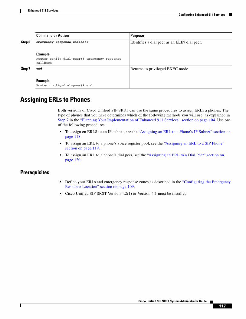
Enhanced 911 ServicesConfiguring Enhanced 911 Services
Assigning ERLs to PhonesBoth versions of Cisco Unified SIP SRST can use the same procedures to assign ERLs a phones. The type of phones that you have determines which of the following methods you will use, as explained in Step 7 in the “Planning Your Implementation of Enhanced 911 Services” section on page 104. Use one of the following procedures:
• To assign en ERLS to an IP subnet, see the “Assigning an ERL to a Phone’s IP Subnet” section on page 118.
• To assign an ERL to a phone’s voice register pool, see the “Assigning an ERL to a SIP Phone” section on page 119.
• To assign an ERL to a phone’s dial peer, see the “Assigning an ERL to a Dial Peer” section on page 120.
Prerequisites
• Define your ERLs and emergency response zones as described in the “Configuring the Emergency Response Location” section on page 109.
• Cisco Unified SIP SRST Version 4.2(1) or Version 4.1 must be installed
Step 6 emergency response callback
Example:Router(config-dial-peer)# emergency response callback
Identifies a dial peer as an ELIN dial peer.
Step 7 end
Example:Router(config-dial-peer)# end
Returns to privileged EXEC mode.
Command or Action Purpose
117Cisco Unified SIP SRST System Administrator Guide
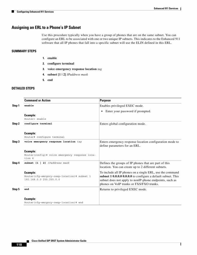
Enhanced 911 ServicesConfiguring Enhanced 911 Services
Assigning an ERL to a Phone’s IP Subnet
Use this procedure typically when you have a group of phones that are on the same subnet. You can configure an ERL to be associated with one or two unique IP subnets. This indicates to the Enhanced 911 software that all IP phones that fall into a specific subnet will use the ELIN defined in this ERL.
SUMMARY STEPS
1. enable
2. configure terminal
3. voice emergency response location tag
4. subnet [1 | 2] IPaddress mask
5. end
DETAILED STEPS
Command or Action Purpose
Step 1 enable
Example:Router> enable
Enables privileged EXEC mode.
• Enter your password if prompted.
Step 2 configure terminal
Example:Router# configure terminal
Enters global configuration mode.
Step 3 voice emergency response location tag
Example:Router(config)# voice emergency response loca-tion 4
Enters emergency response location configuration mode to define parameters for an ERL.
Step 4 subnet [1 | 2] IPaddress mask
Example:Router(cfg-emrgncy-resp-location)# subnet 1 192.168.0.0 255.255.0.0
Defines the groups of IP phones that are part of this location. You can create up to 2 different subnets.
To include all IP phones on a single ERL, use the command subnet 1 0.0.0.0 0.0.0.0 to configure a default subnet. This subnet does not apply to nonIP-phone endpoints, such as phones on VoIP trunks or FXS/FXO trunks.
Step 5 end
Example:Router(cfg-emrgncy-resp-location)# end
Returns to privileged EXEC mode.
118Cisco Unified SIP SRST System Administrator Guide
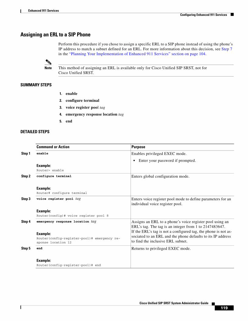
Enhanced 911 ServicesConfiguring Enhanced 911 Services
Assigning an ERL to a SIP Phone
Perform this procedure if you chose to assign a specific ERL to a SIP phone instead of using the phone’s IP address to match a subnet defined for an ERL. For more information about this decision, see Step 7 in the “Planning Your Implementation of Enhanced 911 Services” section on page 104.
Note This method of assigning an ERL is available only for Cisco Unified SIP SRST, not for Cisco Unified SRST.
SUMMARY STEPS
1. enable
2. configure terminal
3. voice register pool tag
4. emergency response location tag
5. end
DETAILED STEPS
Command or Action Purpose
Step 1 enable
Example:Router> enable
Enables privileged EXEC mode.
• Enter your password if prompted.
Step 2 configure terminal
Example:Router# configure terminal
Enters global configuration mode.
Step 3 voice register pool tag
Example:Router(config)# voice register pool 8
Enters voice register pool mode to define parameters for an individual voice register pool.
Step 4 emergency response location tag
Example:Router(config-register-pool)# emergency re-sponse location 12
Assigns an ERL to a phone’s voice register pool using an ERL’s tag. The tag is an integer from 1 to 2147483647. If the ERL’s tag is not a configured tag, the phone is not as-sociated to an ERL and the phone defaults to its IP address to find the inclusive ERL subnet.
Step 5 end
Example:Router(config-register-pool)# end
Returns to privileged EXEC mode.
119Cisco Unified SIP SRST System Administrator Guide
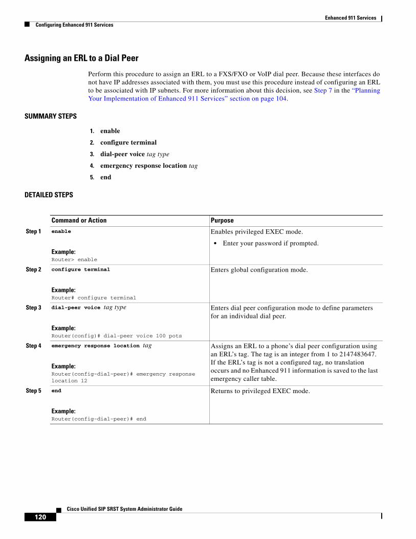
Enhanced 911 ServicesConfiguring Enhanced 911 Services
Assigning an ERL to a Dial Peer
Perform this procedure to assign an ERL to a FXS/FXO or VoIP dial peer. Because these interfaces do not have IP addresses associated with them, you must use this procedure instead of configuring an ERL to be associated with IP subnets. For more information about this decision, see Step 7 in the “Planning Your Implementation of Enhanced 911 Services” section on page 104.
SUMMARY STEPS
1. enable
2. configure terminal
3. dial-peer voice tag type
4. emergency response location tag
5. end
DETAILED STEPS
Command or Action Purpose
Step 1 enable
Example:Router> enable
Enables privileged EXEC mode.
• Enter your password if prompted.
Step 2 configure terminal
Example:Router# configure terminal
Enters global configuration mode.
Step 3 dial-peer voice tag type
Example:Router(config)# dial-peer voice 100 pots
Enters dial peer configuration mode to define parameters for an individual dial peer.
Step 4 emergency response location tag
Example:Router(config-dial-peer)# emergency response location 12
Assigns an ERL to a phone’s dial peer configuration using an ERL’s tag. The tag is an integer from 1 to 2147483647. If the ERL’s tag is not a configured tag, no translation occurs and no Enhanced 911 information is saved to the last emergency caller table.
Step 5 end
Example:Router(config-dial-peer)# end
Returns to privileged EXEC mode.
120Cisco Unified SIP SRST System Administrator Guide

Enhanced 911 ServicesConfiguring Enhanced 911 Services
Configuring Customized SettingsThe E911 settings you can customize are:
• Elin: The default ELIN. If a 911 caller’s IP phone address does not match the subnet of any location in any zone, the default ELIN is used to replace the original automatic number identification (ANI). The default ELIN can be already defined in one of the ERLs or can be unique. If a default ELIN is not defined and there is no match for the 911 caller’s IP address, the PSAP sees the ANI for callback purposes. A syslog message is sent requesting the default ELIN, and no caller location information is available to the PSAP.
• Expiry: The number of minutes a 911 call is associated to an ELIN in case of a callback from the 911 operator. The callback expiry can be changed from a default of 3 hours to any time between 2 minutes and 48 hours. The timer is started the moment the 911 call goes to the PSAP. The PSAP can call back the ELIN and reach the last caller within this expiry time.
• Callback: The default phone number to contact if a 911 callback cannot find the last 911 caller from the Last Caller table. This can happen if the callback occurs after a router has rebooted or if the expiration has elapsed.
• Logging: A syslog informational message is printed to the console every time an emergency call is made. Such a message is required for third party applications to send an e-mail or page to an in-house emergency administrator. This is a default feature that can be disabled using the no logging command. The following is an example of a syslog notification message:
%E911-5-EMERGENCY_CALL_PLACED: calling #[4085550100] called#[911] ELIN [4085550199]
Prerequisites
Cisco Unified SIP SRST Version 4.2(1) must be installed
Restrictions
This feature is not available for Cisco Unified SIP SRST Version 4.1.
SUMMARY STEPS
1. enable
2. configure terminal
3. voice emergency response settings
4. expiry time
5. callback number
6. logging
7. elin number
8. end
121Cisco Unified SIP SRST System Administrator Guide

Enhanced 911 ServicesConfiguring Enhanced 911 Services
DETAILED STEPS
Command or Action Purpose
Step 1 enable
Example:Router> enable
Enables privileged EXEC mode.
• Enter your password if prompted.
Step 2 configure terminal
Example:Router# configure terminal
Enters global configuration mode.
Step 3 voice emergency response settings
Example:Router(config)# voice emergency response set-tings
Enters voice emergency response settings mode to define settings you can customize for E911 calls.
Step 4 expiry time
Example:Router(cfg-emrgncy-resp-settings)# expiry 300
(Optional) Defines the time period (in minutes) that the emergency caller history information for each ELIN is stored in the Last Caller table. The time can be an integer in the range of 2 minutes to 2880 minutes. The default value is 180 minutes.
Step 5 callback number
Example:Router(cfg-emrgncy-resp-settings)# callback 7500
(Optional) Defines the E.164 callback number (for example, a company operator or main help desk) if a 911 callback cannot find the last caller associated to the ELIN.
Step 6 logging
Example:Router(cfg-emrgncy-resp-settings)# no logging
(Optional) Enables syslog messages that announce every emergency call. The syslog messages can be tracked to send pager or e-mail notifications to an in-house support number. By default, logging is enabled. Use the no form of this command to disable logging.
Step 7 elin number
Example:Router(cfg-emrgncy-resp-settings)# elin 4085550100
Specifies the E.164 number to be used as the default ELIN if no ERL has a subnet mask that matches the current 911 caller’s IP phone address.
Step 8 end
Example:Router (cfg-emrgncy-resp-settings)# end
Returns to privileged EXEC mode.
122Cisco Unified SIP SRST System Administrator Guide

Enhanced 911 ServicesConfiguring Enhanced 911 Services
Using the Address Command for Two ELINS
Note This feature is not available for Cisco Unified SIP SRST Version 4.1.
For ERLs that have two ELINs defined, you cannot use just one address field to have two address entries for each ELIN in the ALI database. Instead of entering the specific phone number, a key phrase is entered to represent each ELIN. The show voice emergency address command produces output that replaces the key phrase with the ELIN information and generates two lines of addresses.
To define the expression, use the keyword elin (context-insensitive), followed by a period, the starting position of the ELIN to use, followed by another period, and finally the ending position of the ELIN. For example:
address I,ELIN.1.3,ELIN.4.7,678 ,Alder Drive ,Milpitas ,CA,95035
In the example, the second parameter of address following I are digits 1-3 of each ELIN. The third parameter are digits 4-7 of each ELIN. When you enter the show voice emergency address command, the output will replace the key phrase as seen in the following:
I,408,5550101,678,Alder Drive ,Milpitas ,CA,95035I,408,5550190,678,Alder Drive ,Milpitas ,CA,95035
Enabling Call Detail Records
Note This feature is not available for Cisco Unified SIP SRST Version 4.1.
To conform to internal policy or external regulations, you may be required to save 911 call history data including the following information:
• Original caller’s extension
• ELIN information
• ERL information (the integer tag and the text name)
• Original caller’s phone IP address
These attributes are visible from the RADIUS accounting server and syslog server output, or by using the show call history voice command.
Note You must enable the RADIUS server or the syslog server to display these details. See your RADIUS or syslog server documentation.
123Cisco Unified SIP SRST System Administrator Guide

Enhanced 911 ServicesConfiguring Enhanced 911 Services
Output from a RADIUS Accounting Server
For RADIUS accounting, the emergency call information is under a feature-vsa record. The fields are:
• EMR: Emergency call
• CGN: Original calling number
• ELIN: Emergency line identification number; the translated number
• CDN: Called number
• ERL: Emergency response location tag number
• ERLN: Emergency response location name; the name entered for the ERL, if one exists
• CIP: Caller’s IP address; nonzero for implicit ERL assignments
• ETAG: ERL tag; nonzero for explicit ERL assignments
The following shows an output example from a RADIUS server:
*Jul 18 15:37:43.691: RADIUS: Cisco AVpair [1] 202 "feature-vsa=fn:EMR,ft:07/18/2007 15:37:32.227,frs:0,fid:6,fcid:A2444CAF347B11DC8822F63A1B4078DE,legID:57EC,cgn:6045550101,elin:6045550199,cdn:911,erl:2,erln:Fisco,cip:1.5.6.200,etag:0"
Output from a Syslog Server
If gateway accounting is directed to the syslog server, a VOIP_FEAT_HISTORY system message appears. The feature-vsa parameters are the same ones described for RADIUS accounting.
The following shows an output example from a syslog server:
*Jul 18 15:37:43.675: %VOIPAAA-5-VOIP_FEAT_HISTORY: FEAT_VSA=fn:EMR,ft:07/18/200715:37:32.227,frs:0,fid:6,fcid:A2444CAF347B11DC8822F63A1B4078DE,legID:57EC,cgn:6045550199,elin:6045550100,cdn:911,erl:2,erln:ABCDEFGHIJKLMNOPQRSTUVWXYZ123,cip:1.5.6.200,etag:0,bguid:A23F6AD7347B11DC881DF63A1B4078DE
Output from the show call history voice Command
View emergency call information on the gateway using show call active voice and show call history voice. Some emergency call information is already in existing fields. The original caller’s number is under OriginalCallingNumber. The ELIN is at TranslatedCallingNumber. The four new fields are the ERL, ERL name, the calling phone’s IP address, and any explicit ERL assignments. These fields only appear if an ELIN translation occurs. For example, any 911 calls from an ERL with no ELIN defined do not print the four emergency fields in the show call commands. If no ERLs match the calling phone and the default ELIN is used, the ERL field displays No Match.
The following shows an output example using the show call history voice command:
EmergencyResponseLocation=3 (Cisco Systems 3)ERLAssignment=3DeviceIPAddress=1.5.6.202
124Cisco Unified SIP SRST System Administrator Guide

Enhanced 911 ServicesConfiguring Enhanced 911 Services
Verifying E911 ConfigurationThe following verification procedures are version-specific:
• Version 4.2(1), page 125
• Versions 4.1 and 4.2(1), page 126
Version 4.2(1)
New show commands are introduced to display E911 configuration or usage.
• Use the show voice emergency command to display IP addresses, subnet masks, and ELINs for each ERL.
Router# show voice emergency
EMERGENCY RESPONSE LOCATIONSERL | ELIN 1 | ELIN2 | SUBNET 1 | SUBNET 2 1 | 6045550101 | | 10.0.0.0 | 255.0.0.0 2 | 6045550102 | 6045550106 | 192.168.0.0 | 255.255.0.0 3 | | 6045550107 | 172.16.0.0 | 255.255.0.0 4 | 6045550103 | | 192.168.0.0 | 255.255.0.0 5 | 6045550105 | | 209.165.200.224 | 255.0.0.0 6 6045550198 | | 6045550109 | 209.165.201.0 | 255.255.255.224
• Use the show voice emergency addresses command to display address information for each ERL.
Router# show voice emergency addresses
3850 Zanker Rd, San Jose,604,5550101225 W Tasman Dr, San Jose,604,5550102275 W Tasman Dr, San Jose,604,5550103518 Bellew Dr,Milpitas,604,5550104400 Tasman Dr,San Jose,604,55501053675 Cisco Way,San Jose,604,5550106
• Use the show voice emergency all command to display all ERL information.
Router# show voice emergency all
VOICE EMERGENCY RESPONSE SETTINGS Callback Number: 6045550103 Emergency Line ID Number: 6045550155 Expiry: 2 minutes Logging Enabled
EMERGENCY RESPONSE LOCATION 1 Name: Cisco Systems 1 Address: 3850 Zanker Rd, San Jose,elin.1.3,elin.4.10 IP Address 1: 209.165.200.226 IP mask 1: 255.255.255.254 IP Address 2: 209.165.202.129 IP mask 2: 255.255.0.0 Emergency Line ID 1: 6045550180 Emergency Line ID 2: Last Caller: 6045550188 [Jan 30 2007 16:05.52 PM] Next ELIN For Emergency Call: 6045550166
EMERGENCY RESPONSE LOCATION 3 Name: Cisco Systems 3 Address: 225 W Tasman Dr, San Jose,elin.1.3,elin.4.10 IP Address 1: 209.165.202.133 IP mask 1: 255.255.0.0 IP Address 2: 209.165.202.130 IP mask 2: 255.0.0.0 Emergency Line ID 1:
125Cisco Unified SIP SRST System Administrator Guide

Enhanced 911 ServicesTroubleshooting Enhanced 911 Services
Emergency Line ID 2: 6045550150 Last Caller: Next ELIN For Emergency Call: 6045550151
• Use the show voice emergency zone command to display each zone’s list of locations in order of priority.
Router# show voice emergency zone
EMERGENCY RESPONSE ZONES zone 90 location 4 location 5 location 6 location 7 location 2147483647 zone 100 location 1 priority 1 location 2 priority 2 location 3 priority 3
Versions 4.1 and 4.2(1)
Use the show voice emergency callers command to see the translations made by outbound 911 calls. This command lists the originating number, the ELIN used, and the time for each 911 call. This history is active for only three hours after the call is placed. Expired calls are not shown in this output.
router# show voice emergency callersEMERGENCY CALLS CALL BACK TABLEELIN | CALLER | TIME 6045550100 | 6045550150 | Oct 12 2006 03:59:436045550110 | 8155550124 | Oct 12 2006 04:05:21
Troubleshooting Enhanced 911 ServicesUse the following procedure to trouble enhanced 911 services.
Step 1 Use the debug voice application error and the debug voice application callsetup command. These are existing commands for calls made using the default session or TCL applications.
This example shows the debug output when a call to 911 is made:
router# debug voice application errorrouter# debug voice application callsetup
Nov 10 23:49:05.855: //emrgncy_resp_xlate_callingNum: InDialPeer[20001], OutDialPeer[911] callingNum[6046692003] Nov 10 23:49:05.855: //ER_HistTbl_Find_CallHistory: 6046699100 Nov 10 23:49:05.855: //59//Dest:/DestProcessEmergencyCall: Emergency Call detected: Using ELIN 6046699100
This example shows the debug output when a PSAP calls back an emergency caller:
router# debug voice application errorrouter# debug voice application callsetup
Nov 10 23:49:37.279: //emrgncy_resp_xlate_calledNum: calledNum[6046699100], dpeerTag[6046699]
126Cisco Unified SIP SRST System Administrator Guide

Enhanced 911 ServicesCisco Unified SIP SRST: Examples
Nov 10 23:49:37.279: //ER_HistTbl_Find_CallHistory: 6046699100 Nov 10 23:49:37.279: //HasERHistoryExpired: elapsedTime[10 minutes] Nov 10 23:49:37.279: //67//Dest:/DestProcessEmergencyCallback: Emergency Response Callback: Forward to 6046692003.Nov 10 23:49:37.279: //67//Dest:/DestCaptureCallForward: forwarded to 6046692003 reason 1
Error MessagesThe Enhanced 911 feature introduces a new system error message. The following error message displays if a 911 callback cannot route to the last 911 caller because the saved history was lost because of a reboot, an expiration of an entry, or a software error:
%E911_NO_CALLER: Unable to contact last 911 caller.
Cisco Unified SIP SRST: Examples The following examples are version-specific:
• Version 4.2(1), page 127
• Versions 4.1 and 4.2(1), page 128
Version 4.2(1) Emergency response settings are:
• Default elin if no elin match is found: 604 555-0120
• Expiry time for information in the Last Caller table: 180 minutes
• Callback number if the PSAP operator must call back the 911 caller and the call back history has expired: 604 555-0199
Zone 1 has four locations, 1, 2, 3, and 4, and a name, address, and elin are defined for each location. Each of the four locations is assigned a priority. In this example, because location 4 has been assigned the highest priority, it is the first that is searched for IP subnet matches to identify the ELIN assigned to the 911 caller’s phone. A dial peer is configured to route 911 calls to the PSAP (voice port 1/0/0). Callback dial peers are also configured.
voice emergency response settingselin 6045550120expiry 180callback 6045550199
voice emergency response location 1name Bldg C, Floor 1address I,604,5550135, ,184 ,Main St,Kansas City,KS,1,elin 1 6045550125subnet 1 172.16.0.0 255.255.0.0!voice emergency response location 2name Bldg C, Floor 2address I,elin.1.3,elin.4.7, ,184 ,Main St,Kansas City,KS,2,elin 1 6045550126elin 2 6045550127
127Cisco Unified SIP SRST System Administrator Guide
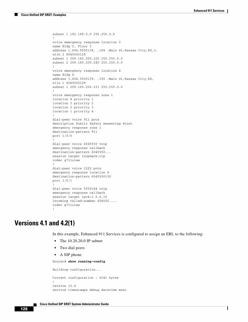
Enhanced 911 ServicesCisco Unified SIP SRST: Examples
subnet 1 192.168.0.0 255.255.0.0!voice emergency response location 3name Bldg C, Floor 3address I,604,5550138, ,184 ,Main St,Kansas City,KS,3,elin 2 6045550128subnet 1 209.165.200.225 255.255.0.0subnet 2 209.165.200.240 255.255.0.0!voice emergency response location 4name Bldg Daddress I,604,5550139, ,192 ,Main St,Kansas City,KS,elin 1 6045550129subnet 1 209.165.200.231 255.255.0.0!voice emergency response zone 1location 4 priority 1location 3 priority 2location 2 priority 3location 1 priority 4!dial-peer voice 911 potsdescription Public Safety Answering Pointemergency response zone 1destination-pattern 911port 1/0/0!dial-peer voice 6045550 voipemergency response callbackdestination-pattern 6045550...session target loopback:rtpcodec g711ulaw!dial-peer voice 1222 potsemergency response location 4destination-pattern 6045550130port 1/0/1!dial-peer voice 5550144 voipemergency response callbacksession target ipv4:1.5.6.10incoming called-number 604555....codec g711ulaw!
Versions 4.1 and 4.2(1)In this example, Enhanced 911 Services is configured to assign an ERL to the following:
• The 10.20.20.0 IP subnet
• Two dial peers
• A SIP phone
Router# show running-config
Building configuration...
Current configuration : 6241 bytes!version 12.4service timestamps debug datetime msec
128Cisco Unified SIP SRST System Administrator Guide

Enhanced 911 ServicesCisco Unified SIP SRST: Examples
service timestamps log datetime msecno service password-encryption!!hostname rm-uut3-2821!boot-start-markerboot-end-marker!no aaa new-modelnetwork-clock-participate wic 1network-clock-participate wic 2no network-clock-participate wic 3!!ip cefno ip dhcp use vrf connected!ip dhcp pool sccp-7912-phone1 host 10.20.20.122 255.255.0.0 client-identifier 0100.1200.3482.cd default-router 10.20.20.3 option 150 ip 10.21.20.218!ip dhcp pool sccp-7960-phone2 host 10.20.20.123 255.255.0.0 client-identifier 0100.131a.a67d.cf default-router 10.20.20.3 option 150 ip 10.21.20.218 dns-server 10.20.20.3!ip dhcp pool sip-phone1 host 10.20.20.121 255.255.0.0 client-identifier 0100.15f9.b38b.a6 default-router 10.20.20.3 option 150 ip 10.21.20.218!ip dhcp pool sccp-7960-phone1 host 10.20.20.124 255.255.0.0 client-identifier 0100.14f2.37e0.00 default-router 10.20.20.3 option 150 ip 10.21.20.218 dns-server 10.20.20.3!!no ip domain lookupip host rm-uut3-c2821 10.20.20.3ip host RescuMe01 10.21.20.218multilink bundle-name authenticated!isdn switch-type basic-net3!!voice service voip allow-connections h323 to h323 allow-connections h323 to sip allow-connections sip to h323 allow-connections sip to sip supplementary-service h450.12 sip registrar server!!voice register global
129Cisco Unified SIP SRST System Administrator Guide
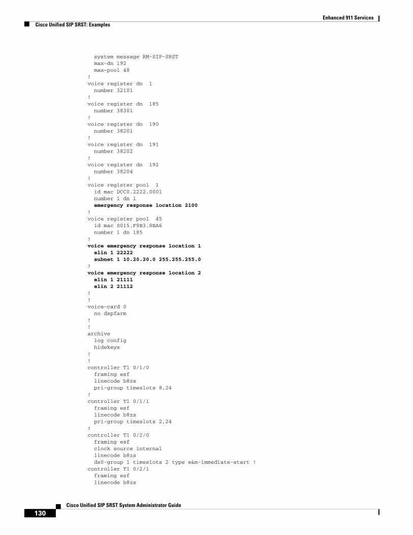
Enhanced 911 ServicesCisco Unified SIP SRST: Examples
system message RM-SIP-SRST max-dn 192 max-pool 48!voice register dn 1 number 32101!voice register dn 185 number 38301!voice register dn 190 number 38201!voice register dn 191 number 38202!voice register dn 192 number 38204!voice register pool 1 id mac DCC0.2222.0001 number 1 dn 1 emergency response location 2100!voice register pool 45 id mac 0015.F9B3.8BA6 number 1 dn 185!voice emergency response location 1 elin 1 22222 subnet 1 10.20.20.0 255.255.255.0!voice emergency response location 2 elin 1 21111 elin 2 21112!!voice-card 0 no dspfarm!!archive log config hidekeys!!controller T1 0/1/0 framing esf linecode b8zs pri-group timeslots 8,24!controller T1 0/1/1 framing esf linecode b8zs pri-group timeslots 2,24!controller T1 0/2/0 framing esf clock source internal linecode b8zs ds0-group 1 timeslots 2 type e&m-immediate-start !controller T1 0/2/1 framing esf linecode b8zs
130Cisco Unified SIP SRST System Administrator Guide

Enhanced 911 ServicesCisco Unified SIP SRST: Examples
pri-group timeslots 2,24!!translation-rule 5 Rule 0 ^37103 1!!translation-rule 6 Rule 6 ^2 911!!interface GigabitEthernet0/0 ip address 31.20.0.3 255.255.0.0 duplex auto speed auto!interface GigabitEthernet0/1 ip address 10.20.20.3 255.255.0.0 duplex auto speed auto!interface Serial0/1/0:23 no ip address encapsulation hdlc isdn switch-type primary-5ess isdn incoming-voice voice no cdp enable!interface Serial0/1/1:23 no ip address encapsulation hdlc isdn switch-type primary-net5 isdn incoming-voice voice no cdp enable!interface Serial0/2/1:23 no ip address encapsulation hdlc isdn switch-type primary-net5 isdn incoming-voice voice no cdp enable!interface BRI0/3/0 no ip address isdn switch-type basic-5ess isdn twait-disable isdn point-to-point-setup isdn autodetect isdn incoming-voice voice no keepalive!interface BRI0/3/1 no ip address isdn switch-type basic-5ess isdn point-to-point-setup!!ip http server!!voice-port 0/0/0!voice-port 0/0/1!
131Cisco Unified SIP SRST System Administrator Guide
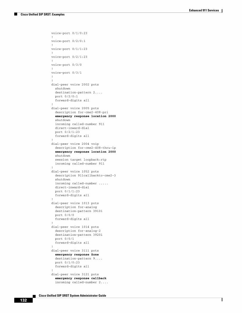
Enhanced 911 ServicesCisco Unified SIP SRST: Examples
voice-port 0/1/0:23!voice-port 0/2/0:1!voice-port 0/1/1:23!voice-port 0/2/1:23!voice-port 0/3/0!voice-port 0/3/1!!dial-peer voice 2002 pots shutdown destination-pattern 2.... port 0/2/0:1 forward-digits all!dial-peer voice 2005 pots description for-cme2-408-pri emergency response location 2000 shutdown incoming called-number 911 direct-inward-dial port 0/2/1:23 forward-digits all!dial-peer voice 2004 voip description for-cme2-408-thru-ip emergency response location 2000 shutdown session target loopback:rtp incoming called-number 911!dial-peer voice 1052 pots description 911callbackto-cme2-3 shutdown incoming called-number ..... direct-inward-dial port 0/1/1:23 forward-digits all!dial-peer voice 1013 pots description for-analog destination-pattern 39101 port 0/0/0 forward-digits all!dial-peer voice 1014 pots description for-analog-2 destination-pattern 39201 port 0/0/1 forward-digits all!dial-peer voice 3111 pots emergency response Zone destination-pattern 9.... port 0/1/0:23 forward-digits all!dial-peer voice 3121 pots emergency response callback incoming called-number 2....
132Cisco Unified SIP SRST System Administrator Guide

Enhanced 911 ServicesCisco Unified SIP SRST: Examples
direct-inward-dial port 0/1/0:23 forward-digits all!!call-manager-fallback max-conferences 8 gain -6 transfer-system full-consult ip source-address 10.20.20.3 port 2000 max-ephones 3 max-dn 3 dual-line preference 1 system message primary SRST-UUT3-2851 keepalive 45!!line con 0 exec-timeout 0 0line aux 0line vty 0 4 login!scheduler allocate 20000 1000!end
rm-uut3-2821#$
133Cisco Unified SIP SRST System Administrator Guide

Enhanced 911 ServicesFeature Information for Enhanced 911 Services
Feature Information for Enhanced 911 ServicesTable 12 lists the enhancements to the Enhanced 911 Services feature by version.
To determine the correct Cisco IOS release to support a specific Cisco Unified SIP SRST version, see the Cisco Unified CME and Cisco IOS Software Version Compatibility Matrix at the following URL: http://www.cisco.com/en/US/docs/voice_ip_comm/cucme/requirements/guide/33matrix.htm.
Use Cisco Feature Navigator to find information about platform support and software image support. Cisco Feature Navigator enables you to determine which Cisco IOS software images support a specific software release, feature set, or platform. To access Cisco Feature Navigator, go to http://www.cisco.com/go/cfn. An account on Cisco.com is not required.
Note Table 12 lists the Cisco Unified SRST version that introduced support for a given feature. Unless noted otherwise, subsequent versions of Cisco Unified SRST software also support that feature.
Where to Go NextSee the Additional References section for more information.
Table 12 Feature Information for Enhanced 911 Services
Feature Name Versions Feature Information
Updates for Enhanced 911 Services 4.2(1) • Assign ERLs to zones
• Define a default ELIN, add a designated callback number, change the expiry time for data in the Last Caller table, enable syslog messages that announce emergency calls
• Add name and address information to 911 caller data
• Add new call detail records
• Add new troubleshooting commands
Enhanced 911 Services 4.1 Enhanced 911 Services was introduced.
134Cisco Unified SIP SRST System Administrator Guide

Enhanced 911 ServicesGlossary
GlossaryRTP—Real-time Transport Protocol. Delivers real-time data over IP packet-switched networks.
SCCP—Skinny Call Control Protocol. A communications protocol between certain clients and Cisco Unified Communications Manager.
SIP—Session Initiation Protocol. An Internet protocol for setting up, maintaining, and terminating multimedia services such as voice calls.
SRST—Survivable Remote Site Telephony. Provides Cisco Unified Communications Manager with fallback support for Cisco Unified IP phones attached to a Cisco router on your local network.
SRTP—Secure Real-time Transport Protocol. Provides encryption and message authentication to RTP.
TCP—Transmission Control Protocol. A transport layer protocol, part of the TCP/IP suite of Internet protocols.
TLS—Transport Layer Security. A security protocol that uses public-key cryptography.
135Cisco Unified SIP SRST System Administrator Guide

Enhanced 911 ServicesGlossary
136Cisco Unified SIP SRST System Administrator Guide

CiscOL-13143-03
I N D E X
A
after-hour exempt command 78
after-hours block pattern command 76
after-hours date command 77
after-hours day command 77
alias command 51
allow-connections command 43
application command 49, 71
authenticate credential command 29
authenticate ood-refer command 28
C
call blocking configuration 75
call-forward b2bua all command 74
call-forward b2bua busy command 74
call-forward b2bua mailbox command 74
call-forward b2bua noan command 74
Cisco CallManager
versions supported by Cisco SRST 14
Cisco Unified IP Phones
supported by each SRST version 14
codec command 71
configuration
call blocking 75
call forwarding 73
Cisco Unified SRST, order of tasks 18
codecs 73
ring sound 72
SIP proxy 50
SIP registrar 46
SIP-to-SIP connection capabilities 42
translation rules 52, 53
voice activity detection (VAD) 72
cor command 51
D
description of SIP SRST 11
digit collect kpml command 32
documentation references 18
dtmf-relay command 52
E
external ring command 71
F
feature roadmap 7
H
hairpin call routing
enabling SIP-to-SIP connections 42
I
incoming called-number command 51
M
max-pool command 71
max registrations command 52
MIBs (Management Information Bases)
137o Unified SIP SRST System Administrator Guide

Index
supported by Cisco Unified SRST 19
N
number command 52
P
platforms
supported by each SRST version 14
preference command 49
prerequisites for configuring Cisco Unified SIP SRST 14
proxy command 49
R
redirect contact order command 63
redirect ip2ip command 40, 61
refer-ood enable command 28
registrar server command
SIP networks 47
restrictions
for each Cisco Unified SRST version 15
RFCs
supported by Cisco Unified SIP SRST 19
S
show dial-peer voice command 56
show voice register dial-peers command 56
SIP SRST description 11
sip-ua command 28
standards
supported by Cisco Unified SRST 19
T
translate-outgoing command 51
138Cisco Unified SIP SRST System Administrator Guide
V
vad command 71
voice-class codec command 49
voice register global command 71
voice register pool command 49, 51, 71, 74, 76
VoIP-to-VoIP connections
configuring 42
OL-13143-03