Sprinkler Protection for Cloud Ceilings - JENSEN … · Sprinkler Protection for Cloud Ceilings...
60
Sprinkler Protection for Cloud Ceilings Final Report Prepared by: Jason Floyd, Ph.D. Joshua Dinaburg Hughes Associates, Inc. Baltimore, MD © July 2013 Fire Protection Research Foundation THE FIRE PROTECTION RESEARCH FOUNDATION ONE BATTERYMARCH PARK QUINCY, MASSACHUSETTS, U.S.A. 02169-7471 E-MAIL: [email protected] WEB: www.nfpa.org/Foundation
Transcript of Sprinkler Protection for Cloud Ceilings - JENSEN … · Sprinkler Protection for Cloud Ceilings...

Sprinkler Protection for Cloud Ceilings
Final Report
Prepared by:
Jason Floyd, Ph.D. Joshua Dinaburg
Hughes Associates, Inc.
Baltimore, MD
© July 2013 Fire Protection Research Foundation
THE FIRE PROTECTION RESEARCH FOUNDATION
ONE BATTERYMARCH PARK QUINCY, MASSACHUSETTS, U.S.A. 02169-7471
E-MAIL: [email protected] WEB: www.nfpa.org/Foundation

—— Page ii ——

—— Page iii ——
FOREWORD Cloud ceilings are ceiling panels that sit beneath the structural ceiling of a room or space and are seen increasingly in commercial and industrial buildings. “Cloud” panels range in area from discrete ceiling panels with large spaces in between, to close-to-full-room-area contiguous coverage with small gaps at the perimeter wall location. NFPA 13, Standard for the Installation of Sprinkler Systems, does not have definitive guidance on automatic sprinkler installation requirements for these ceilings and in some conditions requires sprinklers at both the structural ceiling and cloud ceiling panel elevations. Recent NFPA 13 change proposals were rejected based on a lack of validation of modeling results. The Fire Protection Research Foundation initiated this project to obtain an understanding of how cloud ceiling panels impact sprinkler actuation thresholds with an overall goal to provide the technical basis for sprinkler installation requirements. The focus of this project was developing guidance for sprinkler installation requirements for large, contiguous clouds by determining the maximum gap size between the wall and cloud edge at which ceiling sprinklers are not effective. The Research Foundation expresses gratitude to the report authors Jason Floyd, Ph.D., and Joshua Dinaburg, who are with Hughes Associates, Inc. located in Baltimore, MD. The Research Foundation appreciates the guidance provided by the Project Technical Panelists and all others that contributed to this research effort. Thanks are also expressed to the National Fire Protection Association (NFPA) for providing the project funding through the NFPA Annual Code Fund. The content, opinions and conclusions contained in this report are solely those of the authors.
Keywords: automatic sprinkler systems, cloud ceilings, automatic sprinkler installation

—— Page iv ——

—— Page v ——
PROJECT TECHNICAL PANEL
Roland Asp, National Fire Sprinkler Association
Melissa Avila, Tyco Fire Protection Products
Jarrod Alston, Arup
Cecil Bilbo, Academy of Fire Sprinkler Technologies, Inc
Bob Caputo, Fire and Life Safety America
Dave Fuller, FM Global
Dave Lowrey, City of Boulder Fire Rescue
Jamie Lord, ATF Fire Research Laboratory
Steven Scandaliato, SDG LLC
Tom Wellen, American Fire Sprinkler Association
Karl Wiegand, Global Fire Sprinkler Corporation
Matt Klaus, NFPA Staff Liaison
PROJECT SPONSOR
National Fire Protection Association

—— Page vi ——

FIRE SCIENCE & ENGINEERING
HAI Project # 1JEF00015.000
Sprinkler Protection for Cloud Ceilings
Prepared for: The Fire Protection Research Foundation
One Battery Park Plaza Quincy, MA 02169
Prepared by: Jason Floyd and Joshua Dinaburg
Hughes Associates, Inc. 3610 Commerce Drive, Suite 817
Baltimore, MD 21227 Ph. 410-737-8677 FAX 410-737-8688
www.haifire.com
June 30, 2013

ii HUGHES ASSOCIATES
TABLE OF CONTENTS
Page 1.0 OVERVIEW ....................................................................................................................... 1
2.0 PRIOR RESEARCH ........................................................................................................... 1
2.1 Roof Vents .............................................................................................................. 2
2.2 Perforated Ceilings.................................................................................................. 2
2.3 Cloud Ceilings ........................................................................................................ 3
2.4 Summary of Prior Work.......................................................................................... 3
3.0 CLOUD CEILING EXPERIMENTS AND MODEL VALIDATION .............................. 3
3.1 Description of Experiments .................................................................................... 4
3.1.1 Test Setup.................................................................................................... 4
3.1.2 Test Matrix .................................................................................................. 7
3.2 Results of Testing ................................................................................................... 8
3.2.1 Temperature Results ................................................................................... 8
3.2.2 Sprinkler Results ....................................................................................... 17
3.3 Modeling Results .................................................................................................. 18
3.3.1 Grid Study ................................................................................................. 19
3.3.2 Results of Modeling Full Scale Experiments............................................ 20
4.0 MODELING OF LARGE AREA CLOUDS .................................................................... 21
4.1 Modeling Plan ....................................................................................................... 21
4.1.1 Performance Metric .................................................................................. 21
4.1.2 Model Geometry ....................................................................................... 22
4.1.3 Study Variables ......................................................................................... 23
4.1.4 FDS Parameters ........................................................................................ 24
4.2 Modeling Results .................................................................................................. 26
4.2.1 First Pass Results ...................................................................................... 27
4.2.2 Second Pass ............................................................................................... 31
4.2.3 1.2 m (4 ft) Plenum ................................................................................... 33
4.2.4 Summary of Results for Cloud-Fire Configurations ................................. 35
4.3 Conclusions from Modeling ................................................................................. 36
5.0 SUMMARY ...................................................................................................................... 37
5.1 Model Validation .................................................................................................. 37

iii HUGHES ASSOCIATES
5.2 Recommendations for Gap Sizes .......................................................................... 37
5.2.1 One Part Rule ............................................................................................ 37
5.2.2 Two Part Rule ........................................................................................... 37
5.3 Recommendations for Future Work...................................................................... 38
6.0 REFERENCES ................................................................................................................. 38
APPENDIX A – SAMPLE FDS INPUT FILE............................................................................. 40

1 HUGHES ASSOCIATES
Sprinkler Protection for Cloud Ceilings 1.0 OVERVIEW
Cloud ceilings are increasingly seen in commercial and industrial facilities. The ceilings consist of ceiling panels separated by gaps that are suspended beneath the structural ceiling. Designs for cloud ceilings can vary greatly in terms of the shape and size of the panels, the gaps between panels, and the spacing between the panels and the structural ceiling. The use of cloud ceilings presents challenges for sprinkler protection that are not definitively addressed in NFPA 13. These challenges result from 1) heat from the fire plume entering the gaps between the panels and rising to the structural ceiling which may prevent sprinklers below the clouds from activating and 2) that sprinklers above the clouds may have their spray distribution blocked by the clouds. As a result, in some conditions the code would require sprinklers both below the clouds and at the structural ceiling. Recently a set of code changes was proposed to allow only below cloud sprinklers when the gaps between the clouds were small. Small in this context was suggested as an 8 inch or smaller gap based on modeling performed using Fire Dynamics Simulator (FDS). The proposal was rejected based on a lack of validation for the modeling results. To support being able to provide guidance in NFPA 13 for cloud ceilings, the Fire Protection Research Foundation funded a project for cloud ceilings. This project had the goal of determining sprinkler installation requirements for large contiguous clouds. For the purpose of this project, this was defined as a cloud whose size and cloud-to-cloud spacing would require at least one sprinkler to be installed below the cloud when using a normal flat ceiling sprinkler spacing. Specifically, the project was tasked with determining the maximum separation distance between clouds where structural ceiling sprinklers would not be necessary and/or effective. The research project had three primary tasks. These were: 1. Literature and Modeling Data Review and Gap Analysis 2. Modeling/Evaluation Plan 3. Recommendations for Appropriate Sprinkler Installation Criteria This report documents the result of the project for the three tasks shown above. 2.0 PRIOR RESEARCH
There is little research directly related to cloud ceilings in the literature. There have been a number of research efforts examining the impact of roof vents on sprinkler activation. Other research efforts have examined the impact of beams and similar obstructions to sprinkler activation. Lastly, there has been some research looking at porous ceilings (a suspended ceiling with uniformly distributed holes).

2 HUGHES ASSOCIATES
2.1 Roof Vents
In 1998, NIST completed a large scale experimental and modeling project examining the impacts of roof vents and draft curtains on fire sprinklers1. Both experiments and simulations showed that roof vents had little impact on activation times, unless the fire was directly beneath a vent. The tests used up to four roof vents 1.2 m by 2.4 m (4 ft by 8 ft). The four totaled approximately 2.7 % of the ceiling area within a draft curtain. If, for example, one had an array of 4.6 m by 4.6 m (15 ft by 15 ft) clouds (e.g nominally one sprinkler per cloud), then 2.7 % of the cloud area would correspond to a cloud to cloud gap of 6.2 cm (2.4 in).
In 2001, Beyler and Cooper performed a review of prior roof vent testing2. This included eight tests at various scales with both sprinklers and roof vents. Vent areas ranged from 0.7 % to 4 % of the roof area. A 4 % vent area would correspond to a 9.1 cm (3.6 in) gap around the perimeter of a 4.6 m by 4.6 m (15 ft by 15 ft) cloud. With the exception of tests where the fire was directly below a vent, sprinkler activation times were not greatly different. It is noted that roof vents are large openings in comparison to the equivalent area taken as a perimeter gap.
The roof vent results indicate that if the gap around a large cloud is small (a few percent of the cloud area) that there is unlikely to be a negative impact on below-cloud sprinkler activation. It is noted, however, that a large aspect ratio (long and thin) gap between clouds may have a different impact than a low aspect ratio roof vent.
2.2 Perforated Ceilings
In 1985, Marshall, Feng, and Morgan3 performed a set of experiments looking at the effectiveness of smoke removal through a perforated ceiling. Smoke removal was done both mechanically from above the perforated ceiling and by natural ventilation above the perforated ceiling. The tests were focused on smoke layer development below the ceiling rather than temperature. The testing indicated that a 30 % free area was needed for natural ventilation in order to avoid a deep smoke layer forming beneath the perforated ceiling. This indicates a very conservative upper bound for allowable free area for sprinkler activation. In 1997, SP performed a series of experiments in a 3.2 m (10.5 ft) tall space with a perforated ceiling at 2.4 m (8 ft ) to examine the impact of porosity on smoke detection3. The ceiling was made up of 40 panels, each 6.1 cm (2.5 in) wide. Removing panels resulted in slots running the width of the room. Porosities of 0, 5, 10, 15, 20, 25, 30, and 50 % were tested. The slotted porosity configuration at low porosities is similar to the cloud ceiling configuration. The test data shows large differences (greater than a factor of 2) in detection time at 5 % to 15 % porosity. A 15 % porosity would correspond to a 34.3 cm (13.5 in) gap around the perimeter of a 4.6 m by 4.6 m (15 ft by 15 ft) cloud. It is noted that this 15 % porosity is achieved with narrow gaps (6.1 cm) for a slotted ceiling and is not exactly analogous to the large contiguous cloud. In 2000, Cooper5 derived a set of equations to describe the flow through a perforated ceiling (e.g. large number of small area holes distributed over the ceiling. Using the equations he determined that a significant impact on sprinkler activation was not likely if the porosity ratio (open area / total area) was less than 10 %.

3 HUGHES ASSOCIATES
In 2011, Tsui, et al.6 reported on a series of tests examining sprinkler activation for wood lattice ceilings. The room was 4.5 m (14.8 ft) tall with the perforated ceiling at 3 m (9.8 ft). The ceiling had a porosity of 76 %. Sprinklers were installed below the perforated ceiling and at the structural ceiling. In the four tests with the perforated ceiling, significantly higher temperatures were seen above the perforated ceiling than below. In the one test where visibility allowed for the observation of sprinkler activation, the structural ceiling sprinklers activated first. Given the large porosity, the results of the testing are expected. 2.3 Cloud Ceilings
In 2010, Wellen presented the results of a series of FDS simulations on the issue of cloud ceilings and sprinkler activation7. These simulations formed the basis of a code change proposal to NFPA 13 to allow for the elimination of sprinklers on the structural ceiling when the gap between clouds or between a cloud and the wall was less than 8 inches. The proposal was rejected due to concerns with the validation basis of the simulations.
A total of 61 simulations were performed. Variables included fire growth rate, gap size, ceiling height, cloud size, and fire location. The simulations primarily focused on large clouds (where at least one sprinkler would be on the cloud); however, a few simulations were run with smaller clouds. The simulations were evaluated using both temperature and the activation time of 74 °C (165 °F) sprinklers with an RTI of 50 (m/s)0.5.
The range of variation for the parameters and the matrix of simulations spanned an appropriate range of conditions. The grid size used ranged from 10 to 20 cm (4 to 8 inches). The larger grid size was used for the larger rooms and ceiling heights. For the fire sizes and burner sizes being evaluated, this grid size would be expected to result in reasonable predictions of plume temperatures outside the flame volume. The grid size; however, only resulted in at most a handful of grid cells across the width of the smallest gaps and in many cases less. This is insufficient to allow FDS to model penetration of eddy structures through the gaps. If the impact of this grid size was conservative (e.g. allowed too much heat through the gaps), then the study conclusions would still be valid (however they could be overly conservative). However, if the impact of this grid size was non-conservative, then the study conclusion would be invalid.
2.4 Summary of Prior Work
There is little prior work other than the Wellen study that is directly applicable to sprinkler usage on cloud ceilings. The roof vent and porous ceiling studies offer some limited insight on the issue. Based on the result of those studies, gap sizes exceeding on the order of 10 to 15 % of the cloud area would be expected to fail. That porosity range would result in a gap size similar to that which was recommended in the proposed code change. It is noted that the most directly applicable prior experiment, the SP3 project, was for a single story space.
3.0 CLOUD CEILING EXPERIMENTS AND MODEL VALIDATION
Review of prior work revealed a lack of data specific to cloud ceilings. An experimental program to rigorously evaluate cloud ceiling configurations would be costly and time consuming. Existing results in the FDS validation guide8 indicate there is every reason to expect

4 HUGHES ASSOCIATES
that FDS is capable of predicting the first sprinkler activation time for a fire beneath a cloud ceiling. There are, however, two unknown factors for modeling cloud ceilings. The first factor is how fine the computational grid needs to be to reasonably resolve the flow through the gap between clouds. The second factor is does the needed resolution vary with the specific fire and gap configuration. To address these gaps an experimental plan was developed to conduct a short series of full scale tests to collect validation data. All experiments were then modeled with FDS v6 RC19,10.
3.1 Description of Experiments
3.1.1 Test Setup
Testing utilized an existing test apparatus constructed for a prior FPRF research project on smoke detection in corridors with beams11. The apparatus is a moveable ceiling, see Figure 3-1. The ceiling is 3.7 m (12 ft) wide by 14.6 m (48 ft) long and can be raised up to a height of 6.7 m (22 ft). The ceiling is constructed of gypsum wall board attached to a steel frame. Every 0.9 m (3 ft) along the length is a row of four, vertical, threaded steel rods. These rods were used to attach beams to the ceiling in the prior project. The rods extend approximately 0.4 m (16 in) below the ceiling.
Figure 3-1 – View of HAI movable ceiling
A pair of clouds was constructed using 3/8” gypsum wallboard and attached to the ceiling using the threaded rods with a fender washer and wing nut, see Figure 3-2. Each cloud consisted of two 1.2 m (4 ft) by 2.4 m (8 ft) sheets attached to a pair of 1.2 m (4 ft) by 2.4 m (8 ft) sheets of 1/4” plywood. The plywood served as a stiffener for the gypsum wallboard to help prevent warping and to add strength to prevent the washer from being pulled through the wallboard. Prior to each test, the cloud to floor distance was checked and the wing nuts adjusted if needed. It is estimated that the clouds were level to within one inch. The clouds were suspended 0.3 m (1 ft) below the moveable ceiling and had a 0.15 m (0.5 ft) gap between them.

5 HUGHES ASSOCIATES
Figure 3-2 – Clouds mounted on moveable ceiling
In addition to the pair of clouds, a pair of 2.4 m (8 ft) by 2.7 m (9 ft), free standing walls were constructed, see Figure 3-3. These walls could be positioned to create various burner-wall configurations.
The clouds and the moveable ceiling were instrumented with a total of 34 thermocouples (17 on each). The thermocouple layout for the cloud ceiling is shown in Figure 3-4. The moveable ceiling had thermocouples in the same locations. Thermocouples were mounted 5 cm (2 in) below the surface. Thermocouples at the edges of the clouds were mounted 5 cm (2 in) in from the edge. In addition to the thermocouples, one cloud had a residential, quick response sprinkler with an activation temperature of 74 °C (165 °F) placed at the center of the cloud. The sprinkler pipe was pressurized with air, and a pressure transducer was attached so that the time of sprinkler activation could be determined.

6 HUGHES ASSOCIATES
Figure 3-3 – Setup for test 3 showing the two free standing walls
Figure 3-4 – Cloud ceiling instrumentation
The fire source for each test was a 0.3 m (1 ft) by 0.3 m (1 ft), propane sand burner. For each test a thermocouple tree was attached to the moveable ceiling above the center of the burner. This tree had thermocouples placed at 5 cm (2 in), 15.2 cm (6 in), 30.5 cm (12 in), 45.7 cm (18 in), and 61 cm (24 in) below the moveable ceiling. The burner was controlled by a digital mass flow controller.
TC Location
Sprinkler

7 HUGHES ASSOCIATES
3.1.2 Test Matrix
A total of 10 tests were performed. At least one test was performed for each of the four cloud-wall-burner configurations shown in Figure 3-5. Note, that there is one additional geometry that was not tested in the experimental plan. This geometry is where the burner is located below the intersection of four clouds (i.e. the gaps above the fire form a cross).
Figure 3-5 – Cloud ceiling geometries tested
A total of eight tests were performed. Test variables included geometry, gap size, cloud height, and fire size. A summary of the tests is given in Table 3-1 below.
Table 3-1 — Test Matrix
Test ID Geometry Gap cm (in)
Cloud Height m (ft)
Fire Sizes (kW)
1 Cloud-Wall 15 [6] 2.4 [8] 50, 100, 150 2 Cloud-Wall 30 [12] 2.4 [8] 50, 100, 150
3 Cloud-Cloud-Wall 15 [6] 2.4 [8] 50, 100, 150
4 Cloud-Corner 15[6] 2.4 [8] 50, 100, 150
5 Cloud-Corner 30 [12] 2.4 [8] 50, 100, 150
6 Cloud-Cloud-Slot 15 [6] 2.4 [8] 50, 100, 150
7 Cloud-Cloud-Slot 15 [6] 3.7 [12] 100, 200, 300
8 Cloud-Cloud-Slot 15 [6] 4.9 [16] 100, 200, 300
For each test the desired configuration was established by placing the freestanding walls, moving the burner and burner TC rage, and/or changing the ceiling height. The burner was lit and the mass flow controller set to the first fire size. Temperatures were monitored until steady state conditions were reached. Data collection continued for a short period (on the order of one
Wall
Cloud
Fire
Cloud-Cloud Slot Cloud-Wall
Cloud-Cloud-WallCloud-Corner
Ceiling

8 HUGHES ASSOCIATES
minute), and the fire size was then increased. This was repeated for the third fire size. Approximately two and one half to three minutes were spent at each fire size.
3.2 Results of Testing
3.2.1 Temperature Results
The following eight subsections present the measured ceiling temperatures for the eight tests. Results are shown as two columns of three figures each with the left side representing temperatures below the clouds, the right side representing temperatures below the structural ceiling, and top to bottom increasing fire size. Temperatures represent a time average over approximately one minute of time just prior to increasing to the next fire size (i.e., when conditions had reached a quasi-steady state).

9 HUGHES ASSOCIATES
3.2.1.1 Test 1
Results for Test 1 are shown in Figure 3-6 below. Test results indicate that ambient air movement in the lab resulted in a slight lean of the fire plume as seen in the temperatures of the left cloud panel where the left side temperatures are on average slightly higher than the right side temperatures.
Figure 3-6 – Results for Test 1 (Cloud-Wall, 15 cm gap, 2.4 m ceiling height)
=
39.8
55.8
83.6
43.9
50.0
38.6
32.1
39.0
30.3
21.5
31.6
25.4
50 kW Fire - Below Cloud Ceiling
26.7
28.5
22.6
27.5
26.6
=
56.4
83.8
153.5
69.0
79.6
56.0
43.3
57.9
39.6
24.1
43.9
31.5
100 kW Fire - Below Cloud Ceiling
36.3
38.5
23.8
37.3
40.0
=
73.7
117.5
253.0
93.1
121.8
77.6
59.5
83.3
50.6
31.2
61.9
36.3
150 kW Fire - Below Cloud Ceiling
47.4
52.0
30.6
48.2
53.6
=
76.3
111.5
158.2
98.0
96.1
88.6
56.2
58.6
77.7
52.3
54.1
66.3
100 kW Fire - AboveCloud Ceiling
44.6
56.8
36.2
43.0
64.2
=
111.7
161.7
239.9
140.1
144.8
126.2
78.2
82.6
110.1
71.4
75.7
89.2
150 kW Fire - Above Cloud Ceiling
60.8
77.8
45.8
59.0
85.2
=
49.9
70.3
92.6
61.6
59.3
56.0
39.1
37.8
50.2
37.8
35.9
46.0
50 kW Fire - Above Cloud Ceiling
32.5
38.5
28.5
31.2
45.0

10 HUGHES ASSOCIATES
3.2.1.2 Test 2
Results for Test 2 are shown in Figure 3-7 below. Similar to Test 1, a slight lean in the fire plume is evidenced in the temperatures on the left and right sides of the left cloud panel.
Figure 3-7 – Results for Test 2 (Cloud-Wall, 30 cm gap, 2.4 m ceiling height)
=
31.8
42.9
51.3
35.9
35.8
31.3
24.7
31.6
24.4
20.5
23.7
21.6
50 kW Fire - Below Cloud Ceiling
21.9
21.9
20.4
22.5
29.2
=
46.2
69.7
84.0
54.3
54.9
46.0
31.9
44.8
31.1
22.8
27.7
24.3
100 kW Fire - Below Cloud Ceiling
23.8
23.9
21.9
24.6
42.4
=
59.5
94.2
122.8
72.2
73.5
58.3
48.6
58.5
37.2
26.5
32.0
26.1
150 kW Fire - Below Cloud Ceiling
24.6
26.3
23.3
25.9
56.0
=
49.8
62.6
80.3
55.0
55.2
50.1
35.9
39.6
45.8
35.7
36.1
43.7
50 kW Fire - Above Cloud Ceiling
30.0
38.0
29.5
30.4
51.0
=
73.5
96.6
128.8
83.7
85.9
76.9
52.6
56.9
68.5
52.5
50.6
63.1
100 kW Fire - AboveCloud Ceiling
40.2
53.5
38.3
40.2
78.8
=
101.8
136.8
187.2
116.6
120.3
105.9
73.5
80.3
94.7
70.3
71.2
85.1
150 kW Fire - Above Cloud Ceiling
53.3
72.6
48.0
54.1
105.6

11 HUGHES ASSOCIATES
3.2.1.3 Test 3
Results for Test 3 are shown in Figure 3-8 below. This test also indicate a lean in the plume along the wall as can be seen by comparing locations mirrored across the gap between the clouds.
Figure 3-8 – Results for Test 3 (Cloud-Cloud-Wall, 15 cm gap, 2.4 m ceiling height)
=
29.7
32.8
28.0
29.4
51.4
35.2
80.7
36.3
24.8
62.7
23.8
21.5
50 kW Fire - Below Cloud Ceiling
33.0
24.4
24.1
27.6
22.0
=
43.7
49.1
43.0
46.6
88.5
52.7
131.4
59.2
33.3
93.7
36.2
24.9
100 kW Fire - Below Cloud Ceiling
52.1
32.0
32.1
41.2
26.7
=
56.7
70.0
77.2
65.1
119.2
69.1
153.3
83.1
43.6
114.9
60.1
32.0
150 kW Fire - Below Cloud Ceiling
70.5
49.8
39.7
57.5
34.7
=
29.4
33.7
50.5
49.3
69.5
62.1
90.6
42.5
44.4
83.4
40.7
35.6
50 kW Fire - Above Cloud Ceiling
59.2
39.6
38.3
49.5
26.5
=
42.2
48.0
79.3
77.9
109.7
97.7
137.2
65.2
66.7
123.0
62.6
51.3
100 kW Fire - AboveCloud Ceiling
89.6
56.6
53.0
73.8
33.1
=
59.0
72.0
119.2
105.8
144.6
124.0
156.8
89.7
83.8
143.5
87.0
68.6
150 kW Fire - Above Cloud Ceiling
103.4
74.3
61.1
86.2
41.5

12 HUGHES ASSOCIATES
3.2.1.4 Test 4
Results for Test 4 are shown in Figure 3-9 below. Results show a slight bias to one corner that is small for the 50 kW and 100 kW fires, but more pronounced for the 150 kW fire.
Figure 3-9 – Results for Test 4 (Cloud-Corner, 15 cm gap, 2.4 m ceiling height)
=
56.4
121.2
54.8
92.9
37.5
79.5
29.6
57.1
69.3
28.2
56.0
70.1
50 kW Fire - Above Cloud Ceiling
37.1
63.8
31.3
49.1
170.5=
26.4
53.3
24.0
32.1
32.8
32.4
28.4
29.4
22.7
20.6
22.0
20.5
50 kW Fire - Below Cloud Ceiling
22.2
21.9
20.2
22.4
127.9
=
39.2
91.8
34.0
50.2
46.3
47.8
39.7
43.4
25.6
23.4
25.6
22.6
100 kW Fire - Below Cloud Ceiling
26.4
24.2
22.6
26.2
250.8
=
53.9
125.8
45.2
66.5
59.0
61.0
47.9
56.6
30.3
26.7
30.6
24.9
150 kW Fire - Below Cloud Ceiling
27.9
27.9
24.8
29.0
428.7
=
102.1
238.9
94.2
170.8
68.1
144.4
42.3
109.9
123.5
40.6
107.9
123.1
100 kW Fire - AboveCloud Ceiling
68.4
110.8
52.5
87.8
370.8
=
187.3
382.4
158.9
266.3
119.1
218.5
70.9
165.8
182.1
71.1
164.1
179.2
150 kW Fire - Above Cloud Ceiling
106.2
160.8
78.7
128.6
612.5

13 HUGHES ASSOCIATES
3.2.1.5 Test 5
Results for Test 5 are shown in Figure 3-10 below. Unlike Tests 4, this corner test with the larger gap does not show a significant plume lean towards one side of the corner at the largest fire size.
Figure 3-10 – Results for Test 5 (Cloud-Corner, 30 cm gap, 2.4 m ceiling height)
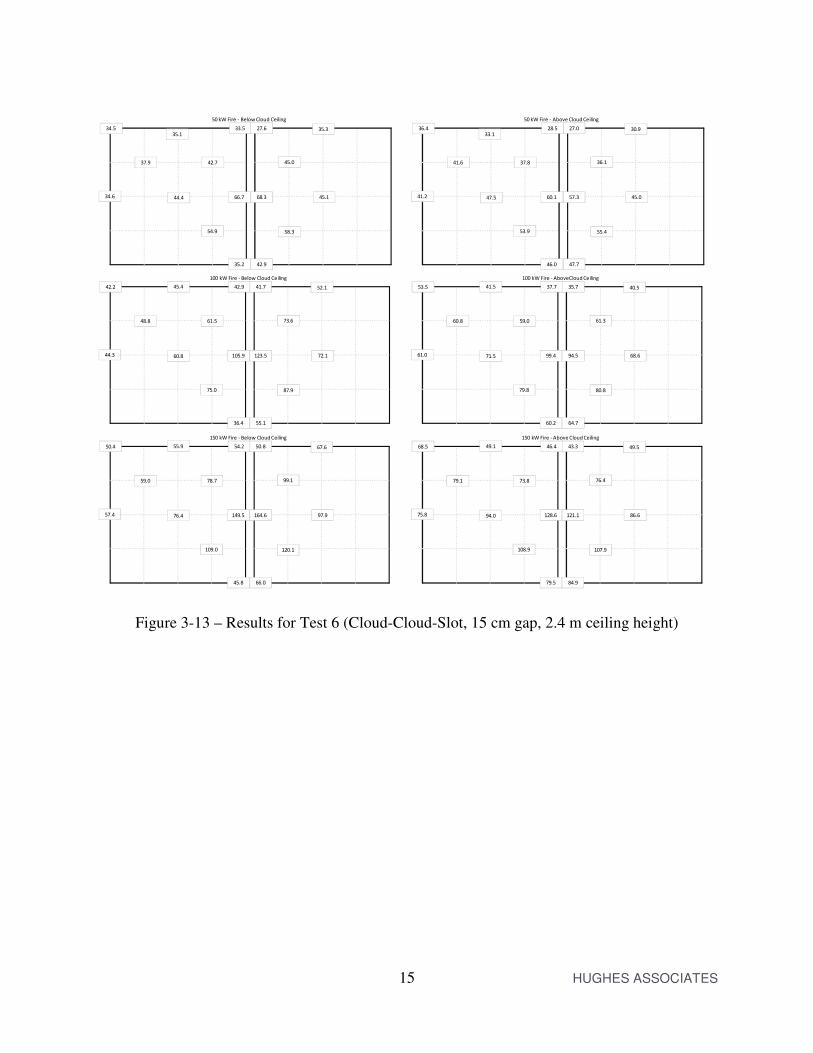
3.2.1.6 Test 6
During the first attempt at Test 6, a noticeable plume lean was seen as shown in Figure 3-11. To reduce the lean a shroud was constructed around the fire. The shroud consisted of a square built from four pieces of drywall measuring 0.6 m (2 ft) by 1.2 m (4 ft) that was then placed on top of four standard bricks. This greatly reduced the plume lean as shown in Figure 3-12. This shroud was also used for Tests 7 and 8. Results for Test 6 are shown in Figure 3-13 below. Results indicate that there is still a slight plume lean.
=
61.1
113.2
62.5
83.1
52.5
72.3
43.0
59.7
65.3
40.8
57.9
65.2
50 kW Fire - Above Cloud Ceiling
43.8
61.8
36.1
47.8
156.1=
22.9
25.8
22.1
23.4
21.6
21.5
20.4
21.8
20.6
20.0
19.9
20.3
50 kW Fire - Below Cloud Ceiling
20.1
19.9
19.8
20.4
35.9
=
29.9
43.4
28.6
27.9
26.3
25.0
23.6
27.2
23.2
22.7
21.9
22.1
100 kW Fire - Below Cloud Ceiling
22.7
22.1
22.2
23.0
89.2
=
42.0
63.0
40.3
36.7
33.7
29.3
26.7
32.7
26.1
26.9
24.8
24.2
150 kW Fire - Below Cloud Ceiling
25.6
24.2
24.6
25.2
164.8
=
106.3
188.4
116.8
132.0
96.1
115.3
75.3
102.2
103.0
72.2
99.3
102.3
100 kW Fire - AboveCloud Ceiling
76.3
98.6
63.4
79.7
280.7
=
200.2
291.5
207.0
195.3
156.4
167.3
122.7
146.5
146.1
115.8
144.0
143.7
150 kW Fire - Above Cloud Ceiling
115.8
137.2
97.5
115.0
460.6

14 HUGHES ASSOCIATES
Figure 3-11 – Plume lean during first attempt at Test 6
Figure 3-12 – Shroud and reduced plume lean for Test 6
15 HUGHES ASSOCIATES
Figure 3-13 – Results for Test 6 (Cloud-Cloud-Slot, 15 cm gap, 2.4 m ceiling height)
=
41.2
41.6
33.1
47.5
37.8
53.9
28.5
60.1
46.0
27.0
57.3
47.7
50 kW Fire - Above Cloud Ceiling
36.1
55.4
30.9
45.0
36.4=
34.6
37.9
35.1
44.4
42.7
54.9
33.5
66.7
35.2
27.6
68.3
42.9
50 kW Fire - Below Cloud Ceiling
45.0
58.3
35.3
45.1
34.5
=
44.3
48.8
45.4
60.8
61.5
75.0
42.9
105.9
36.4
41.7
123.5
55.1
100 kW Fire - Below Cloud Ceiling
73.6
87.9
52.1
72.1
42.2
=
57.4
59.0
55.9
76.4
78.7
109.0
54.2
149.5
45.8
50.8
164.6
66.0
150 kW Fire - Below Cloud Ceiling
99.1
120.1
67.6
97.9
50.4
=
61.0
60.8
41.5
71.5
59.0
79.8
37.7
99.4
60.2
35.7
94.5
64.7
100 kW Fire - AboveCloud Ceiling
61.3
80.8
40.5
68.6
53.5
=
75.8
79.1
49.1
94.0
73.8
108.9
46.4
128.6
79.5
43.3
121.1
84.9
150 kW Fire - Above Cloud Ceiling
76.4
107.9
49.5
86.6
68.5

16 HUGHES ASSOCIATES
3.2.1.7 Test 7
Results for Test 7 are shown in Figure 3-14 below. This test used the shroud from Test 6. As with Test 6 a slight lean to the plume is still seen.
Figure 3-14 – Results for Test 7 (Cloud-Cloud-Slot, 15 cm gap, 3.7 m ceiling height)
=
38.7
41.2
36.0
49.3
48.7
58.7
38.0
65.8
53.8
37.1
64.3
54.4
100 kW Fire - Above Cloud Ceiling
48.6
60.1
36.3
49.3
35.6=
39.5
43.7
43.5
55.2
53.7
63.4
41.8
72.6
44.0
31.3
71.7
45.9
100 kW Fire - Below Cloud Ceiling
52.1
58.3
40.8
50.2
38.1
=
54.4
62.7
63.0
76.5
82.2
93.8
60.7
115.7
60.6
49.6
124.5
67.0
200 kW Fire - Below Cloud Ceiling
84.2
93.1
60.3
79.2
53.1
=
63.0
69.1
62.2
89.2
83.7
108.0
65.7
126.8
79.0
61.8
141.0
98.4
300 kW Fire - Below Cloud Ceiling
102.9
127.4
75.8
104.6
59.6
=
57.3
61.8
48.8
75.8
76.3
94.3
55.3
106.7
77.4
54.2
102.4
79.2
200 kW Fire - AboveCloud Ceiling
72.9
92.7
49.3
65.6
48.2
=
74.5
77.9
59.3
92.2
87.7
114.4
67.6
118.5
99.5
65.3
110.6
99.0
300 kW Fire - Above Cloud Ceiling
76.4
105.2
58.0
62.8
62.5

17 HUGHES ASSOCIATES
3.2.1.8 Test 8
Results for Test 8 are shown in Figure 3-15 below. This test used the shroud from Test 6. As with Test 6 a slight lean to the plume is still seen.
Figure 3-15 – Results for Test 8 (Cloud-Cloud-Slot, 15 cm gap, 4.9 m ceiling height)
3.2.2 Sprinkler Results
Table 3-2 shows the sprinkler activation results for the eight tests. Sprinklers activated in three of the eight tests. In four of the five tests without sprinkler activation, the thermocouple temperature near the sprinkler was within a few degrees of the activation temperature of 74 °C (165 °F) indicating that only a slightly larger fire would be required. For Test 5, the maximum temperature reached at the sprinkler location was only 39 °C; however, this was for a 150 kW fire which is still a fairly small fire. In three of the five tests without sprinkler activation, the gas
=
49.0
53.9
55.1
63.8
68.6
72.4
60.9
81.2
52.0
50.3
81.9
54.3
200 kW Fire - Below Cloud Ceiling
66.2
66.5
52.8
60.8
45.2
=
36.1
39.9
39.9
45.9
47.5
51.5
41.7
51.9
40.6
33.1
49.7
38.1
100 kW Fire - Below Cloud Ceiling
41.5
43.5
35.4
39.6
34.8
=
54.3
59.9
59.0
71.4
75.4
80.4
67.3
91.6
56.6
58.0
91.5
59.5
300 kW Fire - Below Cloud Ceiling
73.3
74.6
58.6
67.4
50.0
=
31.9
34.6
35.1
36.6
40.2
43.8
39.9
49.0
44.4
39.3
49.5
44.7
100 kW Fire - Above Cloud Ceiling
43.6
47.6
35.3
42.3
33.1
=
46.0
51.4
49.4
59.3
65.7
70.8
60.4
78.8
62.5
60.0
77.7
63.7
200 kW Fire - AboveCloud Ceiling
67.1
70.6
48.5
57.0
46.1
=
53.5
58.8
54.5
69.6
74.9
79.9
69.1
88.6
68.7
68.3
87.0
71.0
300 kW Fire - Above Cloud Ceiling
75.7
79.0
55.1
67.1
50.5

18 HUGHES ASSOCIATES
temperature below the structural ceiling above the fire was low. In two tests (both cloud-corner configurations), the gas temperature above the fire was high enough that it could eventually result in damage with a sufficiently long exposure (> 450 °C). Of the configurations tested, this configuration appears that it will drive the maximum permissible gap.
Table 3-2 — Sprinkler Activation Results
Test ID Geometry Gap
(cm [in])
Cloud Height (m [ft])
Fire Size (kW)
Peak Ceiling (°C)
1 Cloud-Wall 15 [6] 2.4 [8] 150 78 2 Cloud-Wall 30 [12] 2.4 [8] DNA (Max 78 °C) 74
3 Cloud-Cloud-Wall 15 [6] 2.4 [8] DNA (Max 71 °C) 157
4 Cloud-Corner 15[6] 2.4 [8] DNA (Max 74 °C) 613
5 Cloud-Corner 30 [12] 2.4 [8] DNA (Max 39 °C) 461
6 Cloud-Cloud-Slot 15 [6] 2.4 [8] 150 129
7 Cloud-Cloud-Slot 15 [6] 3.7 [12] 200 119
8 Cloud-Cloud-Slot 15 [6] 4.9 [16] DNA (Max 78 °C) 89
3.3 Modeling Results
Fire Dynamics Simulator v6 RC1 was used to simulate the 8 tests presented in Section 3.2.1. While not officially released, the beta testing candidate has passed all verification tests and shows a slightly lower relative error (0.34 vs 0.3 in FDS v5) for ceiling jet temperatures. A geometry model was created that included the burner, the clouds, the structural ceiling, any free standing walls present, and a region around the clouds and structural ceiling to prevent artifacts due to the open boundary conditions. For the 2.4 m (8 ft) cloud height this resulted in a geometry measuring 6.2 m by 4.9 m by 3. 0 m (20 ft by 16 ft by 10 ft).

19 HUGHES ASSOCIATES
Figure 3-16 – FDS geometry model for Test 6
3.3.1 Grid Study
A grid study was performed using the Test 1 configuration. The domain was gridded using a uniform grid spacing of 6.4 cm, 4.8 cm, and 3.2 cm. Results are shown in Table 3-3 below. The bias is computed by taking the ratio of the predicted temperature change to the measured temperature change for each thermocouple location. These values are then averaged over all the cloud locations and over all the structural (moveable) ceiling locations. No attempts were made to account for the effect of plume tilt on the temperatures. As seen in the table there is a significant decrease in the error for both locations in going from the 6.4 cm grid to the 4.8 cm grid. From the 4.8 cm to the 3.2 cm grid there is a slight decrease in the error for the cloud location and an increase in the error for the structural ceiling. For the overall study viewpoint, the reduction in the cloud ceiling error will result in better predictions of below cloud sprinkler activation. Therefore, the 4.8 cm grid was selected for use.
Table 3-3 — Grid Study Results
Grid (cm)
Bias Structural Ceiling
Bias Cloud Ceiling
3.2 1.15 0.86 4.8 1.08 0.82
6.4 1.24 0.72

20 HUGHES ASSOCIATES
3.3.2 Results of Modeling Full Scale Experiments
The FDS 6 Validation Report8 contains the results of nine test series which measured ceiling jet temperatures. The tests either used known heat release rates (gas or liquid spray burners) or used pool fires with calorimetry. Experimental error for these tests was estimated as 10 % for the ceiling jet temperature rise measurements. In the validation report, the FDS predictions resulted in a 30 % average error with a 7 % negative bias (e.g. temperatures on average were 7 % low. Larger errors were seen for smaller temperature rises (a 5 °C error for a 20 °C rise is 25 % but only 5 % for a 100 °C rise). The approach used to compute the FDS 6 error and bias was applied to each of the 8 tests and all tests combined. It was applied both separately to the cloud and structural ceiling data and then to the two sets combined. No attempts were made to account for the lean of the plume. Results are shown below in Table 3-4.
Table 3-4 — Model Validation Study Results
Test Relative Error Structural
Bias Structural Ceiling
Relative Error Cloud
Bias Cloud Ceiling
Relative Error Combined
Bias Combined
1 0.52 1.28 0.40 0.90 0.49 1.09 2 0.28 1.30 0.36 0.62 0.50 0.99
3 0.61 1.07 0.59 0.89 0.60 0.98
4 0.52 0.91 0.52 0.60 0.56 0.76
5 0.35 0.86 0.46 0.66 0.44 0.77
6 0.50 1.49 0.23 1.04 0.40 1.27
7 0.32 1.33 0.16 0.94 0.29 1.14
8 0.22 1.31 0.09 0.98 0.20 1.16
All 0.48 1.34 0.46 0.95 0.50 1.15
With the exception of Test 4 and 5 (the corner tests), the combined bias is under 20 % with the structural ceiling tending towards over prediction (bias > 1) and the cloud ceiling tending towards under prediction (bias < 1). With the exception of Test 7 and 8 (the raised ceiling cloud-cloud-slot tests), the model relative errors are generally larger than the 30 % seen in the validation report. However, plume lean will exaggerate this since it will result in regions of higher and lower temperatures. The relative error is based on a least squares, so plume lean will exaggerate relative error. An attempt can be made to account for plume lean by selecting thermocouple pairs on either side of the direction of lean and averaging their results. For example in Tests 1 and 2, if the fire were to lean one direction or the other along the wall, then using the average of the three TC pairs indicated in Figure 3-17 can act to “correct” the data for the plume lean. This logic was applied to all of the tests where applicable and the bias and relative error recomputed.

21 HUGHES ASSOCIATES
Figure 3-17 – Thermocouple pairs to evaluate for plume lean for Tests 1 and 2
Post-plume lean correction the relative error/bias for the structural ceiling, the cloud ceiling, and combined was 0.39/1.26, 0.39/0.99, and 0.40/1.13, respectively. This correction is not completely physical since the decay in temperature of a ceiling jet is not linear with the radius from the plume but rather decays to the 2/3 power12. These “corrected” values are similar to values reported in the FDS validation guide indicating that the selected grid size is performing similarly to the use of FDS on a flat ceiling without clouds. The grid study results indicate that the grid size used in the Wellen study would have under predicted the below cloud temperatures. This suggests that the conclusions reached in the study, while likely valid, are likely over-conservative and that larger gaps might be permissible. 4.0 MODELING OF LARGE AREA CLOUDS
Based upon the literature review and the results of modeling the full scale experiments, a series of FDS simulations were performed to examine the effect of gap size on below cloud sprinkler activation. This section of the report discusses the modeling approach used to extend the Wellen study parameter space for large area clouds and analyzes the results of the modeling. 4.1 Modeling Plan
4.1.1 Performance Metric
The purpose of NFPA 1313 is “to provide to provide a reasonable degree of protection for life and property from fire through standardization of design, installation, and testing requirements
Wall
Cloud
Fire
Ceiling
TC Location
A A
BB
C C

22 HUGHES ASSOCIATES
for sprinkler systems, including private fire service mains, based on sound engineering principles, test data, and field experience.” The goal of this project was to determine configurations where the sprinklers would not be needed (or effective) on the structural ceiling when a cloud ceiling is present. It is obvious, and borne out by prior results, that a porous ceiling will result in increased time to sprinkler activation. Therefore, determining if a cloud configuration would require sprinklers both above and below the clouds means determining at what point the delay in activation prevents a reasonable degree of protection for life and property. Since the listing standards (e.g. UL 19914) for automatic sprinklers do not contain a pre-actuation temperature requirement for the compartment gas or structure, a metric was needed to evaluate the model results. This project decided to apply a similar metric as was done for the FPRF residential sprinkler on sloped ceiling project15. The objective of the criteria was define a performance level that should ensure that life and property would be protected in accordance with the purpose of NFPA 13. The criteria were:
1. Below cloud sprinklers must activate due to the fire plume (e.g. ceiling jet) and not due to the development of a hot layer.
2. The temperature at 1.6 m (63 in) above the floor cannot exceed 93 °C (200 °F) away from the fire and cannot exceed 54 °C (130 °F) for over two minutes – This criterion is intended to maintain tenable conditions for egress.
3. The temperature below either the structural ceiling or the drop ceiling cannot exceed 315 °C (600 °F) at a distance of 50 % of the sprinkler spacing – This criterion is intended to avoid damage to the structural ceiling, prevent the formation of a layer capable of rapid ignition of lightweight, flammable materials, and to avoid damage to the cloud ceiling.
4. The backside temperature of the structural and cloud ceilings must remain below 200 °C (392 °F). This is to avoid significant damage to the structural ceiling or failure of support structures for the cloud ceiling.
Model results for each cloud ceiling configuration simulated were compared the four criteria above. If the below cloud sprinklers activated in time to avoid exceeding one or more of the criteria, then that ceiling cloud configuration was deemed successful.
4.1.2 Model Geometry
All the simulations used a room with a 9.1 m by 9.1 m (30 ft by 30 ft) floor area. This room would require four sprinklers assuming a 4.6 m (15 ft) sprinkler separation. While larger rooms exist in the built environment, a larger room would result in more time for hot layer development (e.g. more likely to violate the third criteria). The room was given four equal area clouds where each cloud had one sprinkler. Modeling larger clouds was deemed unnecessary. If the fire is below a cloud, then sprinklers below the clouds would perform as if they were below a ceiling without clouds. It is only if the fire is at or very near a gap that the fact that it is a cloud ceiling will have a significant impact on the sprinkler performance. For these configurations it is the distance to the nearest sprinkler that would impact the performance and that distance would not change for larger clouds (i.e. would not be more than allowed by the maximum sprinkler spacing).

23 HUGHES ASSOCIATES
The room was modeled with eight sprinklers (four on the structural ceiling and four on the clouds). Sprinkler locations remained constant in plan view. The height of the sprinklers changed to account for the room height and plenum space height. The computer modeling used rooms with four, 4.6 m by 4.6 m (15 ft by 15 ft) clouds. The dimension refers to the distance from gap center to gap center. This represents a minimum cloud size where one sprinkler would be required for each cloud. Larger clouds would result in either the same distance from the gap to the first sprinkler (if the dimension is an integer multiple) or closer (on at least one of the clouds bordering the gap). The cloud to structural ceiling distance will be 0.61 m (2 ft) or 1.2 m (4 ft). Larger distances would reduce the temperature on the structural ceiling and be less conservative and significantly smaller distances would be atypical. The room will be 9.1 m (30 ft) on each side (e.g. four clouds). While larger room sizes are possible, they would result in a lower temperature at head level. A single, standard door was present to ensure adequate fire ventilation. A sketch of the geometry is shown in Figure 4-1.
Figure 4-1 – Geometry for FDS study of large area clouds
4.1.3 Study Variables
The computer modeling varied gap size, ceiling height, fire location, fire growth rate, and plenum height as indicated below:
• Based upon the prior experimental work, a gap size of approximately 30 cm (12 in) would be the upper limit for a 2.4 m (8 ft) ceiling, or since plume width scales with height, 12.5 %. This suggests upper limits for gaps of 30 cm to 130 cm (12 in to 51 in) for the range of ceiling heights being modeled in this study. The first pass of modeling used gap widths of 6.25 % and 12 % of ceiling height. These gap sizes were then adjusted based on results.
• Heights to the cloud ceiling were 2.4 m, 4.3 m, 6.1 m, and 10.4 m (8 ft, 14 ft, 20 ft, and 34 ft).
9.1 m (30 ft)
Va
rie
s
Door
Cloud Panel
Va
rie
s
Varies

24 HUGHES ASSOCIATES
• Five fire locations were used: cloud-corner, cloud-wall, cloud-cloud-wall, cloud-cloud-slot, and cloud-cross. Fire locations are shown in Figure 4-2.
• Two fire growth rates were used: medium (growth rate constant = 0.0111 kW/s2) and fast (growth rate constant = 0.0444 kW/s2).
• Two plenum heights were used: 0.6 m (2 ft) and 1.2 m (4 ft).
Figure 4-2 – Test Configurations for Full Scale Testing
Modeling was performed in multiple passes. The first pass did permutations of all ceiling heights, fire locations, and growth rates with gaps of 6.25 % and 12.5 % of the ceiling height using the 0.6 m (2 ft) plenum. The results of each pair of simulations were used to adjust the gap size on a selected subset of simulations for a second pass. A subset of the 0.6 m (2 ft) plenum cases were run with a 1.2 m (4 ft) plenum to evaluate the impact of plenum height in a third set of simulations.
4.1.4 FDS Parameters
The following sections discuss the FDS inputs used for simulating the cloud ceiling variable space discussed in the previous section. Each FDS simulation was run until the first activation of a sprinkler on a cloud ceiling, at which point the run was automatically terminated. In a few cases this resulted in no structural ceiling sprinkler activating at the point in time the run was terminated. 4.1.4.1 Computational Grid
All simulations used the multi-mesh feature of FDS. 5 cm (2 in) meshes were placed from the structural ceiling to 30 cm (1 ft) below the clouds and placed to a distance of 1.5 m (5 ft) around the fire from the floor to the cloud mesh. The finer mesh is equivalent to the mesh size determined in the grid sensitivity study in Section 3.3.1. 15 cm meshes (6 in) were used for the
Wall
Cloud
Fire
Cloud-Cloud Slot Cloud-Cloud Cross
Cloud-Wall Slot Cloud-Cloud-WallCloud-Corner

25 HUGHES ASSOCIATES
remainder of the compartment. A small mesh was placed outside the door to the compartment to allow for proper flow development from the door prior to reaching an open boundary of the computational domain.
Figure 4-3 – Example of Meshing Strategy (8 ft ceiling, Cloud-Cloud-Wall configuration)
4.1.4.2 Fire
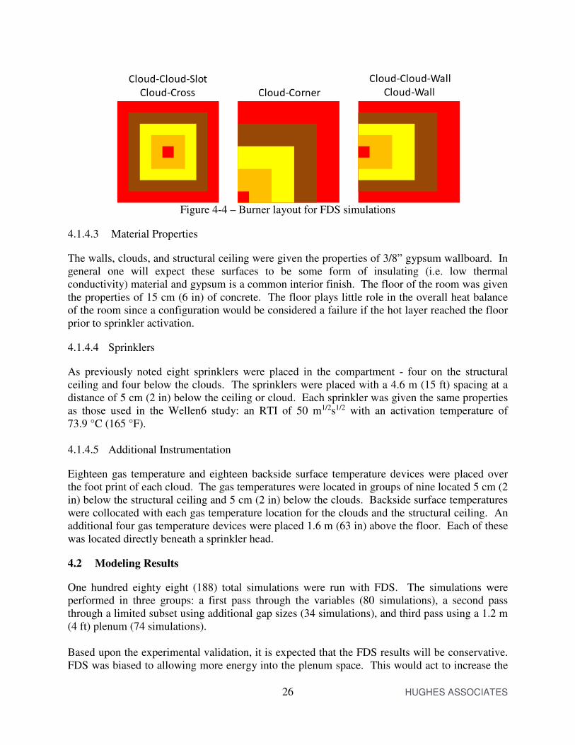
The performance metrics for this study are purely thermal requirements. Therefore, the critical parameters are the heat release rate, the fire growth rate, and the heat release per unit area. Soot and CO yields and the specific fuel chemistry will have a minor impact. The fuel source used for this analysis was propane and the fire was specified using a heat release rate per unit area of 1.7 MW/m2. This value is representative of hazards such as small stacks of wood pallets, polyurethane foam furniture, empty boxes, and particle board furniture16 which are reasonable analogs of typical commercial and office combustibles. Since plume entrainment is a function of the buoyancy head and the plume diameter, the fire was implemented as five concentric squares from 0.3048 m by 0.3048 m (1 ft by 1 ft) to 1.524 m by
1.524 m (5 ft by 5 ft). The FDS &RAMP input was used to ramp the innermost ring from 0 MW/m2 to 1.7 MW/m2 at the desired medium or fast growth rate. Once the innermost ring
reached its maximum heat release per unit area, a new &RAMP input was used for the next larger
ring, and so on until all rings reached their maximum heat release per unit area. The ring positions were adjusted to keep the fire origin below the cloud gap, see Figure 4-4.
26 HUGHES ASSOCIATES
Figure 4-4 – Burner layout for FDS simulations
4.1.4.3 Material Properties
The walls, clouds, and structural ceiling were given the properties of 3/8” gypsum wallboard. In general one will expect these surfaces to be some form of insulating (i.e. low thermal conductivity) material and gypsum is a common interior finish. The floor of the room was given the properties of 15 cm (6 in) of concrete. The floor plays little role in the overall heat balance of the room since a configuration would be considered a failure if the hot layer reached the floor prior to sprinkler activation.
4.1.4.4 Sprinklers
As previously noted eight sprinklers were placed in the compartment - four on the structural ceiling and four below the clouds. The sprinklers were placed with a 4.6 m (15 ft) spacing at a distance of 5 cm (2 in) below the ceiling or cloud. Each sprinkler was given the same properties as those used in the Wellen6 study: an RTI of 50 m1/2s1/2 with an activation temperature of 73.9 °C (165 °F). 4.1.4.5 Additional Instrumentation
Eighteen gas temperature and eighteen backside surface temperature devices were placed over the foot print of each cloud. The gas temperatures were located in groups of nine located 5 cm (2 in) below the structural ceiling and 5 cm (2 in) below the clouds. Backside surface temperatures were collocated with each gas temperature location for the clouds and the structural ceiling. An additional four gas temperature devices were placed 1.6 m (63 in) above the floor. Each of these was located directly beneath a sprinkler head.
4.2 Modeling Results
One hundred eighty eight (188) total simulations were run with FDS. The simulations were performed in three groups: a first pass through the variables (80 simulations), a second pass through a limited subset using additional gap sizes (34 simulations), and third pass using a 1.2 m (4 ft) plenum (74 simulations). Based upon the experimental validation, it is expected that the FDS results will be conservative. FDS was biased to allowing more energy into the plenum space. This would act to increase the
Cloud-Cloud-Slot
Cloud-Cross Cloud-Corner
Cloud-Cloud-Wall
Cloud-Wall

27 HUGHES ASSOCIATES
activation time of below cloud sprinklers, increase the temperature at the structural ceiling, and result in an increase in the incidence of cloud sprinkler activation via hot layer vs. ceiling jet. The result of each of these effects means that if FDS indicates a cloud-fire configuration passes for a specific room geometry, then there is little risk accepting that result. Conversely, if FDS indicates a failure, then that failure may not be a valid prediction; however, from a life and property protection point of view accepting that outcome as a failure is not harmful. 4.2.1 First Pass Results
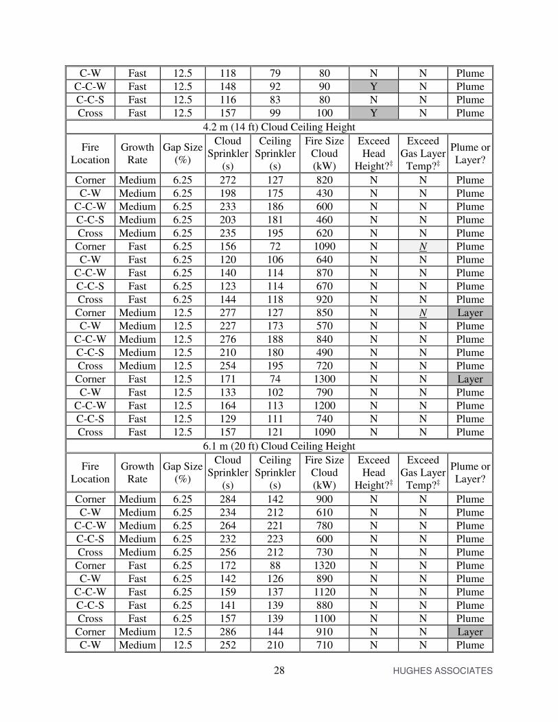
FDS simulations were made for all permutations of fire location, growth rate, 6.25 % and 12.5 % gap, and ceiling height for a 0.6 m (2 ft) plenum height. Results of the simulations are tabulated in Table 4-1 and show the time of activation of the first cloud sprinkler and the first structural ceiling sprinkler, the fire size at the time of the first cloud sprinkler, and the last three columns in the table respectively represent criteria 2, 3, and 1 from Section 4.1.1. The plume vs. layer criteria was determined by visual inspection of temperature slice files as shown in Figure 4-5. If the sprinkler primarily saw the ceiling jet from the fire plume, then it was considered to have been activated by the plume. If the sprinkler primarily saw high temperature due to the hot layer dropping below the cloud, then it was considered to have been activated by the layer. To account for uncertainty in the FDS results, the temperature thresholds were evaluated at 10 % and 30 % below the critical temperature for each criteria. Simulations that failed using the 10 % reduced temperature values were considered failed, and simulations that failed using the 30 % reduced temperature values were noted as borderline results.
Table 4-1 — Results of first pass simulations (6.25 % and 12.5 % gaps with a 0.6 m (2 ft) plenum)
2.4 m (8 ft) Cloud Ceiling Height
Fire Location
Growth Rate
Gap Size (%)
Cloud Sprinkler
(s)
Ceiling Sprinkler
(s)
Fire Size @Cloud
(kW)
Exceed Head
Height?‡
Exceed Gas Layer
Temp?‡
Plume or Layer?
Corner Medium 6.25 230 110 590 N N Plume
C-W Medium 6.25 167 121 310 N N Plume
C-C-W Medium 6.25 196 147 430 N N Plume
C-C-S Medium 6.25 164 146 300 N N Plume
Cross Medium 6.25 206 148 470 N N Plume
Corner Fast 6.25 133 66 780 N N Plume
C-W Fast 6.25 101 79 450 N N Plume
C-C-W Fast 6.25 116 91 590 N N Plume
C-C-S Fast 6.25 99 95 430 N N Plume
Cross Fast 6.25 125 95 690 N N Plume
Corner Medium 12.5 273 110 110 N N Layer
C-W Medium 12.5 196 128 130 N N Plume
C-C-W Medium 12.5 254 150 150 Y N Plume
C-C-S Medium 12.5 191 133 130 N N Plume
Cross Medium 12.5 245 157 160 Y N Plume
Corner Fast 12.5 164 66 70 Y N Layer
28 HUGHES ASSOCIATES
C-W Fast 12.5 118 79 80 N N Plume
C-C-W Fast 12.5 148 92 90 Y N Plume
C-C-S Fast 12.5 116 83 80 N N Plume
Cross Fast 12.5 157 99 100 Y N Plume
4.2 m (14 ft) Cloud Ceiling Height
Fire Location
Growth Rate
Gap Size (%)
Cloud Sprinkler
(s)
Ceiling Sprinkler
(s)
Fire Size Cloud (kW)
Exceed Head
Height?‡
Exceed Gas Layer
Temp?‡
Plume or Layer?
Corner Medium 6.25 272 127 820 N N Plume
C-W Medium 6.25 198 175 430 N N Plume
C-C-W Medium 6.25 233 186 600 N N Plume
C-C-S Medium 6.25 203 181 460 N N Plume
Cross Medium 6.25 235 195 620 N N Plume
Corner Fast 6.25 156 72 1090 N N Plume
C-W Fast 6.25 120 106 640 N N Plume
C-C-W Fast 6.25 140 114 870 N N Plume
C-C-S Fast 6.25 123 114 670 N N Plume
Cross Fast 6.25 144 118 920 N N Plume
Corner Medium 12.5 277 127 850 N N Layer
C-W Medium 12.5 227 173 570 N N Plume
C-C-W Medium 12.5 276 188 840 N N Plume
C-C-S Medium 12.5 210 180 490 N N Plume
Cross Medium 12.5 254 195 720 N N Plume
Corner Fast 12.5 171 74 1300 N N Layer
C-W Fast 12.5 133 102 790 N N Plume
C-C-W Fast 12.5 164 113 1200 N N Plume
C-C-S Fast 12.5 129 111 740 N N Plume
Cross Fast 12.5 157 121 1090 N N Plume
6.1 m (20 ft) Cloud Ceiling Height
Fire Location
Growth Rate
Gap Size (%)
Cloud Sprinkler
(s)
Ceiling Sprinkler
(s)
Fire Size Cloud (kW)
Exceed Head
Height?‡
Exceed Gas Layer
Temp?‡
Plume or Layer?
Corner Medium 6.25 284 142 900 N N Plume
C-W Medium 6.25 234 212 610 N N Plume
C-C-W Medium 6.25 264 221 780 N N Plume
C-C-S Medium 6.25 232 223 600 N N Plume
Cross Medium 6.25 256 212 730 N N Plume
Corner Fast 6.25 172 88 1320 N N Plume
C-W Fast 6.25 142 126 890 N N Plume
C-C-W Fast 6.25 159 137 1120 N N Plume
C-C-S Fast 6.25 141 139 880 N N Plume
Cross Fast 6.25 157 139 1100 N N Plume
Corner Medium 12.5 286 144 910 N N Layer
C-W Medium 12.5 252 210 710 N N Plume

29 HUGHES ASSOCIATES
C-C-W Medium 12.5 291 220 940 N N Plume
C-C-S Medium 12.5 237 222 620 N N Plume
Cross Medium 12.5 277 226 850 N N Layer
Corner Fast 12.5 181 90 1460 N N Plume
C-W Fast 12.5 153 122 1040 N N Plume
C-C-W Fast 12.5 178 133 1400 N N Plume
C-C-S Fast 12.5 145 134 930 N N Plume
Cross Fast 12.5 170 138 1280 N N Plume
10.4 m (34 ft) Cloud Ceiling Height
Fire Location
Growth Rate
Gap Size (%)
Cloud Sprinkler
(s)
Ceiling Sprinkler
(s)*
Fire Size Cloud (kW)
Exceed Head
Height?‡
Exceed Gas Layer
Temp?‡
Plume or Layer?
Corner Medium 6.25 315 236 1100 N N Plume
C-W Medium 6.25 294 274 960 N N Plume
C-C-W Medium 6.25 312 286
DNA 1080 N N Plume
C-C-S Medium 6.25 287 DNA 920 N N Plume
Cross Medium 6.25 307 294 1040 N N Plume
Corner Fast 6.25 187 134 1550 N N Plume
C-W Fast 6.25 176 163 1370 N N Plume
C-C-W Fast 6.25 192 174 1640 N N Plume
C-C-S Fast 6.25 177 DNA 1400 N N Plume
Cross Fast 6.25 189 181 1590 N N Plume
Corner Medium 12.5 323 236 1160 N N Layer
C-W Medium 12.5 305 275 1030 N N Plume
C-C-W Medium 12.5 333 288 1240 N N Plume
C-C-S Medium 12.5 289 286 930 N N Plume
Cross Medium 12.5 316 286 1110 N N Plume
Corner Fast 12.5 198 135 1750 N N Layer
C-W Fast 12.5 184 162 1510 N N Plume
C-C-W Fast 12.5 200 172 1780 N N Plume
C-C-S Fast 12.5 181 176 1460 N N Plume
Cross Fast 12.5 192 179 1640 N N Plume *DNA = Did not activate during simulation, ‡Underline+Italic indicates borderline result.

30 HUGHES ASSOCIATES
Figure 4-5 – Determining plume (left) vs. layer activation (right). Data are below cloud
temperatures
The following observations are made based on the first pass results:
• The worst-case fire location is the cloud-corner configuration. The two-sided entrainment forces the plume into the corner and results in more heat moving through the gap as shown in Figure 4-6. While the cloud-cross and cloud-cloud-wall configurations have a total gap area that represents a larger fraction of the fire area, their more favorable entrainment conditions result in a smaller fraction of the plume area than the corner fire.
• The best-case fire location is cloud-cloud-slot configuration closely followed by the cloud-cloud-wall configuration. For these configurations the gap size as a fraction of the overall plume area is at its lowest resulting in the formation of a clear ceiling jet along the cloud panels as shown in Figure 4-7.
• At activation of the cloud sprinkler, there are high gas temperatures directly over the fire for the corner fire simulations; however, for all configurations gas temperatures away from the impingement point remain low. Large hot layers are not developing prior to sprinkler activation.
• The backside ceiling and cloud temperatures are remaining at levels below concern.
• As the ceiling height increases, the difference in time between a structural ceiling sprinkler and a cloud sprinkler decreases.
• For cloud heights over 4.3 m (14 ft), high head level temperatures do not occur.
• For the 2.4 m (8 ft) cloud height, high head level temperatures occur with 12.5 % gaps.
• For the cloud-corner configuration, gap sizes of 12.5 % result in sprinkler activation via the dropping of the hot layer below the cloud.
• Fast fire growth rates have a slightly higher risk of layer activation vs. plume activation.

31 HUGHES ASSOCIATES
Figure 4-6 – Cloud-corner, 2.4 m (8 ft) ceiling, 0.6 m (2 ft) plenum, 6.25 % gap width showing
flame location and compartment temperatures
Figure 4-7 – Cloud-cloud-slot (left) and cloud-wall (right), 2.4 m (8 ft) ceiling, 0.6 m (2 ft) plenum, 12.5 % gap width, fast growth. Data are below cloud temperatures
4.2.2 Second Pass
From the first pass results it was clear that the corner fire was the worst case configuration for all the scenarios. The results also suggest that the fast fire growth rates increase the chance of activation by the hot layer dropping below the clouds. A second pass varying gap sizes to larger and smaller gaps was made through a subset of the matrix of runs in Table 4-1. The results from this second pass are shown in Table 4-2.

32 HUGHES ASSOCIATES
Table 4-2 — Results of second pass simulations (0.6 m (2 ft) plenum)
2.4 m (8 ft) Cloud Ceiling Height
Fire Location
Growth Rate
Gap Size (%)
Cloud Sprinkler
(s)
Ceiling Sprinkler
(s)
Fire Size Cloud (kW)
Exceed Head
Height?‡
Exceed Gas Layer
Temp?‡
Plume or Layer?
Corner Medium 9.375 247 114 680 N N Plume
Corner Fast 9.375 149 70 980 Y Y Plume
Corner Medium 15.625 237 116 630 N N Layer
Corner Fast 15.625 153 70 1040 N Y Layer
C-C-W Fast 15.625 153 91 1040 Y N Layer
C-C-W Medium 18.75 240 147 640 N N Layer
C-C-W Fast 18.75 154 92 1050 Y Y Layer
C-C-S Fast 18.75 116 96 600 N N Plume
C-W Fast 18.75 130 82 750 N N Plume
Cross Fast 9.375 127 103 710 N N Plume
4.2 m (14 ft) Cloud Ceiling Height
Fire Location
Growth Rate
Gap Size (%)
Cloud Sprinkler
(s)
Ceiling Sprinkler
(s)
Fire Size Cloud (kW)
Exceed Head
Height?‡
Exceed Gas Layer
Temp?‡
Plume or Layer?
Corner Medium 9.375 253 130 710 N N Plume
Corner Fast 9.375 156 80 1090 N Y Plume
Corner Medium 18.75 247 132 680 N N Layer
Corner Fast 18.75 155 79 1060 N N Layer
C-C-W Fast 15.625 164 110 1190 N N Layer
C-C-W Fast 18.75 167 109 1240 N N Layer
C-W Fast 18.57 145 101 930 N N Layer
C-W Fast 21.875 155 101 1070 N N Layer
C-C-S Fast 18.75 136 114 820 N N Plume
C-C-S Fast 21.875 139 114 850 N N Plume
Cross Fast 15.625 155 120 1070 N N Plume
Cross Fast 18.75 156 122 1090 N N Layer
6.1 m (20 ft) Cloud Ceiling Height
Fire Location
Growth Rate
Gap Size (%)
Cloud Sprinkler
(s)
Ceiling Sprinkler
(s)
Fire Size Cloud (kW)
Exceed Head
Height?‡
Exceed Gas Layer
Temp?‡
Plume or Layer?
Corner Medium 18.75 258 154 740 N N Layer
Corner Fast 18.75 165 92 1210 N N Layer
C-W Fast 18.75 157 116 1100 N N Plume
C-C-W Fast 18.75 171 124 1300 N N Layer
C-C-S Fast 18.75 146 134 950 N N Plume
Cross Fast 18.75 171 140 1300 N N Plume
10.4 m (34 ft) Cloud Ceiling Height
Fire Growth Gap Size Cloud Ceiling Fire Size Exceed Exceed Plume or

33 HUGHES ASSOCIATES
Location Rate (%) Sprinkler (s)
Sprinkler (s)*
Cloud (kW)
Head Height?‡
Gas Layer Temp?‡
Layer?
Corner Fast 18.75 181 121 1450 N N Layer
C-W Fast 18.75 181 151 1450 N N Layer
C-C-W Fast 18.75 194 156 1680 N N Layer
C-C-S Fast 18.75 181 171 1460 N N Plume
Cross Medium 18.75 307 279 1050 N N Plume
Cross Fast 18.75 188 174 1560 N N Plume ‡Underline+Italic indicates borderline result. The following observations are made from this table:
• As gap sizes are increased past 12.5 %, there is a greatly increased incidence of the hot layer driving sprinkler activation.
• The gap sizes for the cloud-corner and the cloud-cloud-wall configurations appear to be the limiting gaps.
4.2.3 1.2 m (4 ft) Plenum
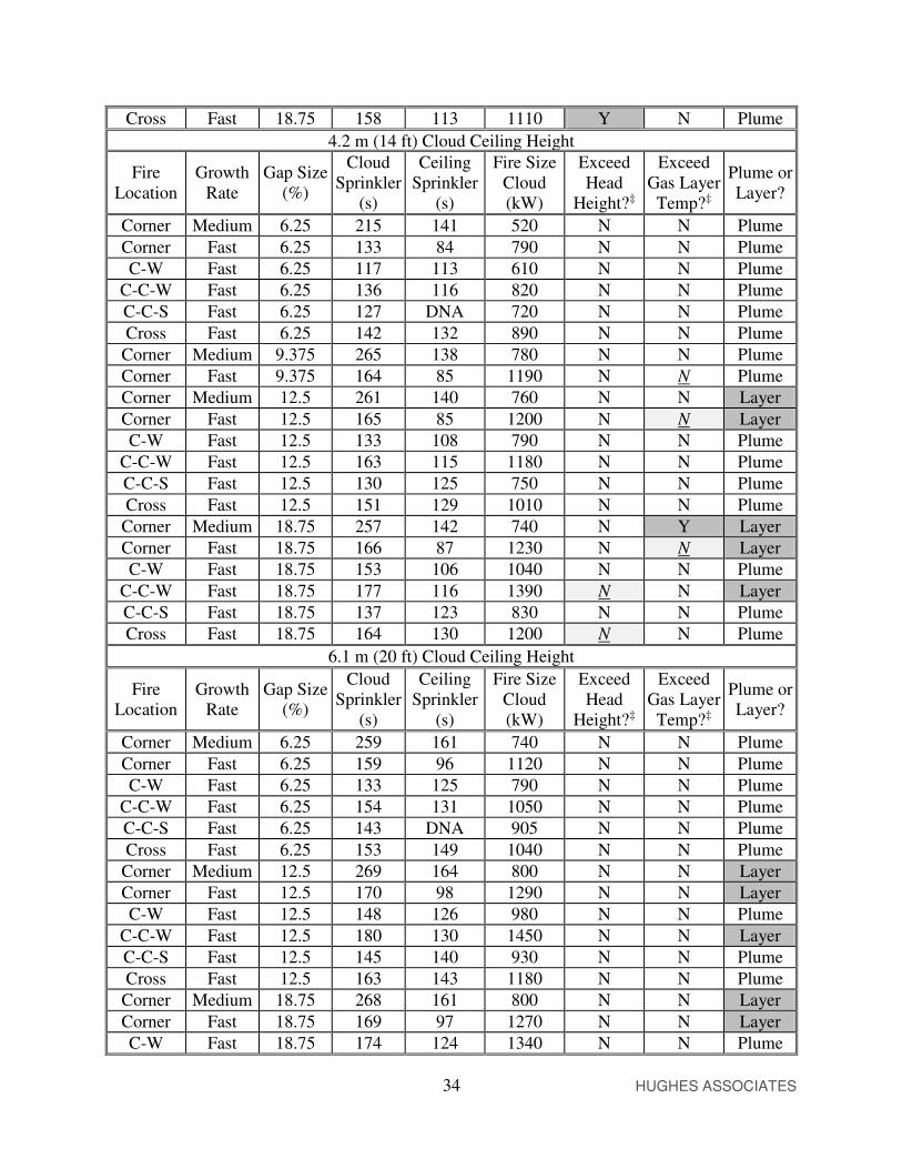
Each fire location and ceiling was simulated using a 1.2 m (4 ft) plenum for at least three gap sizes. The results are shown in Table 4-3.
Table 4-3 — Results of simulations for a 1.2 m (4 ft) plenum
2.4 m (8 ft) Cloud Ceiling Height
Fire Location
Growth Rate
Gap Size (%)
Cloud Sprinkler
(s)
Ceiling Sprinkler
(s)
Fire Size Cloud (kW)
Exceed Head
Height?‡
Exceed Gas Layer
Temp?‡
Plume or Layer?
Corner Medium 6.25 199 117 440 N N Plume
Corner Fast 6.25 120 71 640 N N Plume
C-W Fast 6.25 99 94 430 N N Plume
C-C-W Fast 6.25 111 DNA 550 N N Plume
C-C-S Fast 6.25 100 101 450 N N Plume
Cross Fast 6.25 116 DNA 600 N N Plume
Corner Medium 12.5 263 121 770 N N Plume
Corner Fast 12.5 155 72 1070 N Y Plume
C-W Fast 12.5 112 91 560 N N Plume
C-C-W Fast 12.5 146 97 950 N N Plume
C-C-S Fast 12.5 113 104 570 N N Plume
Cross Fast 12.5 145 111 930 Y N Plume
Corner Medium 18.75 264 118 780 N Y Layer
Corner Fast 18.75 167 72 1230 N Y Layer
C-W Fast 18.75 128 90 730 N N Plume
C-C-W Fast 18.75 163 98 1180 Y N Plume
C-C-S Fast 18.75 119 102 630 N N Plume
34 HUGHES ASSOCIATES
Cross Fast 18.75 158 113 1110 Y N Plume
4.2 m (14 ft) Cloud Ceiling Height
Fire Location
Growth Rate
Gap Size (%)
Cloud Sprinkler
(s)
Ceiling Sprinkler
(s)
Fire Size Cloud (kW)
Exceed Head
Height?‡
Exceed Gas Layer
Temp?‡
Plume or Layer?
Corner Medium 6.25 215 141 520 N N Plume
Corner Fast 6.25 133 84 790 N N Plume
C-W Fast 6.25 117 113 610 N N Plume
C-C-W Fast 6.25 136 116 820 N N Plume
C-C-S Fast 6.25 127 DNA 720 N N Plume
Cross Fast 6.25 142 132 890 N N Plume
Corner Medium 9.375 265 138 780 N N Plume
Corner Fast 9.375 164 85 1190 N N Plume
Corner Medium 12.5 261 140 760 N N Layer
Corner Fast 12.5 165 85 1200 N N Layer
C-W Fast 12.5 133 108 790 N N Plume
C-C-W Fast 12.5 163 115 1180 N N Plume
C-C-S Fast 12.5 130 125 750 N N Plume
Cross Fast 12.5 151 129 1010 N N Plume
Corner Medium 18.75 257 142 740 N Y Layer
Corner Fast 18.75 166 87 1230 N N Layer
C-W Fast 18.75 153 106 1040 N N Plume
C-C-W Fast 18.75 177 116 1390 N N Layer
C-C-S Fast 18.75 137 123 830 N N Plume
Cross Fast 18.75 164 130 1200 N N Plume
6.1 m (20 ft) Cloud Ceiling Height
Fire Location
Growth Rate
Gap Size (%)
Cloud Sprinkler
(s)
Ceiling Sprinkler
(s)
Fire Size Cloud (kW)
Exceed Head
Height?‡
Exceed Gas Layer
Temp?‡
Plume or Layer?
Corner Medium 6.25 259 161 740 N N Plume
Corner Fast 6.25 159 96 1120 N N Plume
C-W Fast 6.25 133 125 790 N N Plume
C-C-W Fast 6.25 154 131 1050 N N Plume
C-C-S Fast 6.25 143 DNA 905 N N Plume
Cross Fast 6.25 153 149 1040 N N Plume
Corner Medium 12.5 269 164 800 N N Layer
Corner Fast 12.5 170 98 1290 N N Layer
C-W Fast 12.5 148 126 980 N N Plume
C-C-W Fast 12.5 180 130 1450 N N Layer
C-C-S Fast 12.5 145 140 930 N N Plume
Cross Fast 12.5 163 143 1180 N N Plume
Corner Medium 18.75 268 161 800 N N Layer
Corner Fast 18.75 169 97 1270 N N Layer
C-W Fast 18.75 174 124 1340 N N Plume

35 HUGHES ASSOCIATES
C-C-W Fast 18.75 179 129 1420 N N Layer
C-C-S Fast 18.75 150 139 1000 N N Plume
Cross Fast 18.75 179 146 1420 N N Plume
10.4 m (34 ft) Cloud Ceiling Height
Fire Location
Growth Rate
Gap Size (%)
Cloud Sprinkler
(s)
Ceiling Sprinkler
(s)*
Fire Size Cloud (kW)
Exceed Head
Height?‡
Exceed Gas Layer
Temp?‡
Plume or Layer?
Corner Medium 6.25 308 216 1050 N N Plume
Corner Fast 6.25 181 126 1450 N N Plume
C-W Fast 6.25 169 159 1270 N N Plume
C-C-W Fast 6.25 184 161 1510 N N Plume
C-C-S Fast 6.25 177 DNA 1390 N N Plume
Cross Fast 6.25 181 DNA 1450 N N Plume
Corner Medium 12.5 319 217 1130 N N Layer
Corner Fast 12.5 203 126 1830 N N Layer
C-W Fast 12.5 188 156 1570 N N Plume
C-C-W Fast 12.5 200 166 1770 N N Plume
C-C-S Fast 12.5 181 175 1450 N N Plume
Cross Fast 12.5 187 180 1550 N N Plume
Corner Medium 18.75 319 215 1130 N N Layer
Corner Fast 18.75 206 126 1890 N N Layer
C-W Fast 18.75 207 157 1910 N N Plume
C-C-W Fast 18.75 213 164 2020 N N Layer
C-C-S Fast 18.75 191 177 1630 N N Plume
Cross Fast 18.75 194 180 1670 N N Plume *DNA = Did not activate during simulation, ‡Underline+Italic indicates borderline result. The following observations are made from the 1.2 m (4 ft) plenum height simulations:
• The increased plenum depth reduces the incidence of layer activation of the cloud sprinklers.
• The increased plenum depth increases the incidence of high ceiling temperature for the 2.4 m (8 ft) and 4.2 m (14 ft) cloud ceiling heights. This suggests that there is a small layer contribution to the sprinkler activations in the 0.6 m (2 ft) plenum cases.
• The cloud-corner and cloud-cloud-wall configurations are still the most limiting scenarios.
4.2.4 Summary of Results for Cloud-Fire Configurations
4.2.4.1 Cloud-Corner
With the 0.6 m (2 ft) plenum, the cloud-corner configuration passes all the criteria at a 6.25 % gap, partially fails at a 9.375 % gap, and fully fails at a 12.5 % gap. This applies to all ceiling heights. At the lower ceiling heights failure is the head level and layer sprinkler activation criteria. At higher ceiling heights, the failure is the layer activation criteria. Borderline hot layer
36 HUGHES ASSOCIATES
temperatures are also seen at the failure points. The partial failure with a 9.375 % gap was a head level temperature failure at a 2.4 m (8 ft) ceiling height. At 9.375 % the temperature was 94.5 °C (10 % reduced threshold of 85.7 °C) and at 6.25 % the temperature was 62.8 °C. A linear interpolation gives an 8.5 % gap to reach the 10 % reduced threshold of 85.7 °C. Similar results are obtained for the 1.2 m (4 ft) plenum. 4.2.4.2 Cloud-Wall
The cloud-wall configuration passed at a gap size of 12.5 % for a 0.6 m (2 ft) plenum and at a gap size of 18.75 % for a 1.2 m (4 ft) plenum. Failures were due to the hot layer activating the sprinklers. This configuration was favorable to the development of a ceiling jet beneath the cloud. 4.2.4.3 Cloud-Cloud-Wall
The cloud-cloud-wall configuration failed at a gap size 12.5 % for a 0.6 m (2 ft) plenum and a 2.4 m (8 ft) ceiling height. For other ceiling heights with the 0.6 m (2 ft) plenum, the cloud-cloud-wall configuration failed at a gap size of 15.625 %. The 1.2 m (4 ft) plenum failed at a gap size 18.75 %; however, 15.625 % was not run for the 4 ft plenum. 4.2.4.4 Cloud-Cloud-Slot
The cloud-cloud-slot configuration did not experience failures for any of the gap sizes tested. 4.2.4.5 Cloud-Cross
Failures of the cloud-cross configuration are seen at the 12.5 % gap size for both the 0.6 m (2 ft) plenum and the 1.2 m (4 ft) plenum. Failures are seen at multiple ceiling heights at that gap size. At the 2.4 m (8 ft) ceiling height the failure was for the head level temperature. At 9.375 % the cloud-cross configuration passed for the 2.4 m (8 ft) ceiling height (the only height tested for that gap size for this configuration). An interpolation between the 12.5 % gap and the 9.375 % gap indicates a 10 % gap would be permissible for this configuration. 4.3 Conclusions from Modeling
In general there was not a large variance in permissible gap size as a function of height for a given cloud-fire configuration. The criteria that failed may have varied over the height, but the gap size at which failure occurred remained fairly constant. With the exception of the cloud-wall configuration, the plenum height also did not have a large impact on the permissible gap size. The most restrictive gap size was the cloud-corner configuration with a gap size of 8.5 %. The least restrictive was the cloud-cloud-slot configuration which did not fail for the gap sizes tested. It is noted that an 8.5 % gap for an 8 ft cloud height is an 8 in gap which is the maximum gap size recommended in the Wellen study. However, the current study indicates that one could allow that gap to be proportionately larger for higher ceiling heights.

37 HUGHES ASSOCIATES
In actuality, although there are five cloud-fire configurations, there are only two gap types: a gap between a cloud and a wall and a gap between two clouds. All the fire configurations result from combining one or more of these gap types. The cloud-corner configuration, therefore, places the tightest restriction on the gap between a cloud and a wall. The most restrictive cloud-fire configuration for a gap between two clouds was the cloud-cross configuration. A general rule, therefore, could be made by either specifying the most restrictive gap size for all gap types or by specifying a gap size for each gap type. 5.0 SUMMARY
5.1 Model Validation
A small series of full scale experiments was conducted to collect data on the fire plume dynamics beneath a cloud ceiling. Collecting data that maintained symmetry proved challenging due to ambient air flows in the lab space that was used. Nonetheless, FDS simulations of the experiments resulted in predictions that, when corrected for asymmetries, had a similar bias and error as compared to other data sets in the FDS validation guide. 5.2 Recommendations for Gap Sizes
The result of modeling a large number of configurations of room geometry and cloud-fire configuration was that the permissible gap size is a function of ceiling height. Two potential rule sets are proffered based upon these results: a single rule applied to any cloud and a two part rule with variance for cloud-wall and cloud-cloud gaps. 5.2.1 One Part Rule
For cloud ceilings where the clouds and structural ceiling are of non-combustible construction, the clouds are sufficiently large and spaced such that each cloud will have at least one sprinkler based upon the normal listed spacing, and where the clouds are level and co-planar, sprinklers can be omitted on the structural ceiling if:
• The gap between a wall and any cloud or between two adjacent clouds is less than or equal to 1 inch of gap per foot of ceiling height.
5.2.2 Two Part Rule
For cloud ceilings where the clouds and structural ceiling are of non-combustible construction, the clouds are sufficiently large and spaced such that each cloud will have at least one sprinkler based upon the normal listed spacing, and where the clouds are level and co-planar, sprinklers can be omitted on the structural ceiling if:
• The gap between a wall and any cloud is less than or equal to 1 inch of gap per foot of ceiling height, or
• The gap between any two adjacent clouds is less than or equal to 1 ¼ inch of gap per foot of ceiling height.

38 HUGHES ASSOCIATES
5.3 Recommendations for Future Work
The study documented in this report was limited in scope. It only examined large-area, non-combustible clouds with the further limitations of level ceiling and equal cloud heights. This leaves a number of potential cloud configurations that were not covered by this report. It is recommended that this work be extended to include:
• Examine the impact of having adjacent clouds at different heights. Since below cloud sprinkler activation results from the fire plume impinging on the cloud and creating a ceiling jet, having adjacent clouds at different heights should have little impact on sprinkler activation. This should be verified, however, with a brief study.
• If clouds are small enough (or have a large enough aspect ratio) that at least one sprinkler per cloud is not required based upon the listed sprinkler spacing, then a ceiling jet might encounter additional gaps between clouds. Depending upon the gap size and cloud size, the ceiling jet may not have the strength (e.g. velocity) to jump the gap in order to reach a sprinkler. Conditions under which only below cloud sprinklers would be allowed for small area clouds are likely to be much more limited than for large area clouds. A study of similar effort to this study is recommended.
• The presence of sloped ceilings and/or sloped clouds will affect the development and movement of the ceiling jet from the fire. A study of similar effort to this study is recommended to examine the impact of ceiling and cloud slope.
• This study examined clouds with a square, uniform shape resulting in a constant gap size between the clouds. More complex shapes could result in a non-uniform gap size between the clouds. A study examining this effect should be conduction. For large area clouds, it is likely that the result will be some form of area averaged gap width. At its most conservative using the maximum gap distance for a large area clouds and this study’s gap recommendations would suffice.
• The ceiling and layer temperatures allowed for this study may exceed those tolerated by clouds made of combustible materials or whose structure involves temperature sensitivity materials (thermoplastics, aluminum). A study to assess the impact of lower temperature thresholds should be conducted.
• This study did not examine the impact of HVAC systems. Cloud ceiling systems are sometimes used to delineate air supply or exhaust locations when the plenum is part of the HVAC system. The effect of this on gap sizes should be examined.
6.0 REFERENCES
1. McGrattan, K., Hamins, A., and Stroup, D. (1998), “International Fire Sprinkler, Smoke & Heat Vent, Draft Curtain, Fire Test Project,” Fire Protection Research Foundation, Quincy, MA.
2. Beyler, C. and Cooper, L. (2001), “Interactions of Sprinklers with Smoke and Heat Vents,” Fire Technology, 37:9-35.
3. Marshall, N., Feng, S., and Morgan, H. (1985), “The Influence of a Perforated False Ceiling on the Performance of Smoke Ventilation Systems,” Fire Safety Journal, 8:227-237.

39 HUGHES ASSOCIATES
4. Isaksson, S., Persson, B., and Tuovinen, H. (1997), “CFD-Simulations of Fire Detection in a Room with a Perforated Suspended Ceiling,” SP Report 1997:43, SP Swedish National Testing and Research Institute, Borås, Sweden.
5. Cooper, L., (2000) “Response of Sprinklers Deployed Below Perforated Ceilings,” HAI Internal Report, Hughes Associates Inc., Baltimore, MD.
6. Tsui, F., Chow, W., et al. (2011), “Experimental Room Fire Studies with Perforated Suspended Ceilings,” Fire Safety Science Proceedings of 10th International Symposium, IAFSS, College Park, MD.
7. Wellen, T. (2010) “FDS Model of Architectural Gaps in Ceilings, How Big is too Big?,” 2010 NFPA Conference, National Fire Protection Association, Las Vegas, NV.
8. McGrattan, K., et al. (2012), “Fire Dynamics Simulator (Version 6) Technical Reference Guide, Volume 3: Validation,” NIST SP 1018, National Institute of Standards and Technology, Gaithersburg, MD.
9. McGrattan, K., et al. (2012), “Fire Dynamics Simulator (Version 6) Technical Reference Guide, Volume 1: Mathematical Model,” NIST SP 1018, National Institute of Standards and Technology, Gaithersburg, MD.
10. McGrattan, K., et al. (2012), “Fire Dynamics Simulator (Version 6) User’s Guide,” NIST SP 1019, National Institute of Standards and Technology, Gaithersburg, MD.
11. Mealy, C., Floyd, J., and Gottuk, D. (2008), “Smoke Detector Spacing Requirements Complex Beamed and Sloped Ceilings, Volume 1: Experimental Validation of Smoke Detector Spacing Requirements,” The Fire Protection Research Foundation, Quincy, MA.
12. Alpert, R., (2008), “Ceiling Jet Flows,” SPFE Handbook of Fire Protection Engineering, Chapter 2-2, Society of Fire Protection Engineers, Bethesda, MD.
13. NFPA 13 (2010), Standard for the Installation of Sprinkler Systems, National Fire Protection Association, Quincy, MA.
14. Underwriters Laboratories Inc. (1997), “Standard for Automatic Sprinklers for Fire-Protection Service,” UL-199, Northbrook, IL.
15. Floyd, J., Budnick, E., Boosinger, M., Dinaburg, J., and Boehmer, H. (2010), “Analysis of the Performance of Residential Sprinkler Systems with Sloped or Sloped and Beamed Ceilings,” The Fire Protection Research Foundation, Quincy, MA.
16. Karlsson, B. and Quintiere, J., Enclosure Fire Dynamics, CRC Press, Boca Raton, FL, 2000.

40 HUGHES ASSOCIATES
APPENDIX A – SAMPLE FDS INPUT FILE
Below is a sample FDS input file. This file is for a 2.4 m (8 ft) ceiling with a 0.6 m (2 ft) plenum height, 9.375 % gap, and a fast growth rate fire. By selectively commenting / uncommenting &MESH, &OBST, and &SURF blocks the fire location and growth rate can be changed. Each ceiling height and gap size had its own template file.
&HEAD CHID='8_Ccross_Fast_2ft_9p375',TITLE='8 ft ceiling, 9.375 gap, cloud
cross fast fire, baseline activation'/
&MESH XB = 9.144,11.2776,3.81,5.334,0,2.4384,IJK=14,10,16/
&MESH XB = 0,9.144,0,9.144,1.8288,3.048,IJK=180,180,24/
!&MESH XB = 0,3.048,0,3.048,0,1.8288,IJK=60,60,36/Corner
!&MESH XB = 3.048,9.144,0,9.144,0,1.8288,IJK=40,60,12/Corner
!&MESH XB = 0,3.048,3.048,9.144,0,1.8288,IJK=20,40,12/Corner
!&MESH XB = 0,3.048,0.,4.572,0,1.8288,IJK=60,90,36/Cloud-Wall
!&MESH XB = 3.048,9.144,0.,4.572,0,1.8288,IJK=30,40,12/Cloud-Wall
!&MESH XB = 0.,9.144,4.572,9.144,0,1.8288,IJK=30,60,12/Cloud-Wall
!&MESH XB = 0,3.048,2.286,6.858,0,1.8288,IJK=60,90,36/Cloud-Cloud-Wall
!&MESH XB = 0,9.144,0.00,2.286,0,1.8288,IJK=60,15,12/Cloud-Cloud-Wall
!&MESH XB = 0,9.144,6.858,9.144,0,1.8288,IJK=60,15,12/Cloud-Cloud-Wall
!&MESH XB = 3.048,9.144,2.286,6.858,0,1.8288,IJK=40,30,12/Cloud-Cloud-Wall
!&MESH XB = 0,4.572,2.286,6.858,0,1.8288,IJK=90,90,36/Cloud-Cloud-Slot
!&MESH XB = 0,9.144,0.00,2.286,0,1.8288,IJK=60,15,12/Cloud-Cloud-Slot
!&MESH XB = 0,9.144,6.858,9.144,0,1.8288,IJK=60,15,12/Cloud-Cloud-Slot
!&MESH XB = 4.572,9.144,2.286,6.858,0,1.8288,IJK=30,30,12/Cloud-Cloud-Slot
&MESH XB = 2.286,6.858,2.286,6.858,0,1.8288,IJK=90,90,36/Cloud-Cross
&MESH XB = 0,9.144,0,2.286,0,1.8288,IJK=60,15,12/Cloud-Cross
&MESH XB = 0,9.144,6.858,9.144,0,1.8288,IJK=60,15,12/Cloud-Cross
&MESH XB = 0,2.286,2.286,6.858,0,1.8288,IJK=15,30,12/Cloud-Cross
&MESH XB = 6.858,9.144,2.286,6.858,0,1.8288,IJK=15,30,12/Cloud-Cross
&TIME T_END=600./
&VENT XB=9.144,11.2776,3.81,3.81,0,2.4384,SURF_ID='OPEN'/
&VENT XB=9.144,11.2776,5.334,5.334,0,2.4384,SURF_ID='OPEN'/
&VENT XB=11.2776,11.2776,3.81,5.334,0,2.4384,SURF_ID='OPEN'/
&VENT XB=9.144,11.2776,3.81,5.334,2.4384,2.4384,SURF_ID='OPEN'/
&VENT PBZ=0.,SURF_ID='Concrete'/
&OBST XB=9.124,9.194,3.81,4.1148,0,2.4384/DoorWall
&OBST XB=9.124,9.194,5.334,5.0292,0,2.4384/DoorWall
&OBST XB=9.124,9.194,4.1148,5.0292,2.1336,2.4384/DoorWall
&OBST XB = 0.2286,4.4577,0.2286,4.4577,2.438,2.488/8 ft
&OBST XB = 0.2286,4.4577,4.6863,8.9154,2.438,2.488/8 ft
&OBST XB = 4.6863,8.9154,0.2286,4.4577,2.438,2.488/8 ft
&OBST XB = 4.6863,8.9154,4.6863,8.9154,2.438,2.488/8 ft
!&OBST XB = 0.000,9.144,0.000,9.144,2.438,2.488/8 ft NoGap Cloud Ceiling

41 HUGHES ASSOCIATES
!&OBST XB=0.,1.5240,0.,1.5420,0.,0.05,SURF_IDS='FIRE5','Concrete','Concrete'/
Corner
!&OBST XB=0.,1.2192,0.,1.2192,0.,0.05,SURF_IDS='FIRE4','Concrete','Concrete'/
Corner
!&OBST XB=0.,0.9144,0.,0.9144,0.,0.05,SURF_IDS='FIRE3','Concrete','Concrete'/
Corner
!&OBST XB=0.,0.6096,0.,0.6096,0.,0.05,SURF_IDS='FIRE2','Concrete','Concrete'/
Corner
!&OBST XB=0.,0.3048,0.,0.3048,0.,0.05,SURF_IDS='FIRE1','Concrete','Concrete'/
Corner
!&OBST
XB=0.,1.5240,1.5240,3.0480,0.,0.05,SURF_IDS='FIRE5','Concrete','Concrete'/
Cloud-Wall
!&OBST
XB=0.,1.2192,1.6764,2.8956,0.,0.05,SURF_IDS='FIRE4','Concrete','Concrete'/
Cloud-Wall
!&OBST
XB=0.,0.9144,1.8288,2.7432,0.,0.05,SURF_IDS='FIRE3','Concrete','Concrete'/
Cloud-Wall
!&OBST
XB=0.,0.6096,1.9812,2.5908,0.,0.05,SURF_IDS='FIRE2','Concrete','Concrete'/
Cloud-Wall
!&OBST
XB=0.,0.3048,2.1336,2.4384,0.,0.05,SURF_IDS='FIRE1','Concrete','Concrete'/
Cloud-Wall
!&OBST
XB=0.,1.5240,3.8100,5.3340,0.,0.05,SURF_IDS='FIRE5','Concrete','Concrete'/
Cloud-Cloud-Wall
!&OBST
XB=0.,1.2192,3.9624,5.1816,0.,0.05,SURF_IDS='FIRE4','Concrete','Concrete'/
Cloud-Cloud-Wall
!&OBST
XB=0.,0.9144,4.1148,5.0292,0.,0.05,SURF_IDS='FIRE3','Concrete','Concrete'/
Cloud-Cloud-Wall
!&OBST
XB=0.,0.6096,4.2672,4.8768,0.,0.05,SURF_IDS='FIRE2','Concrete','Concrete'/
Cloud-Cloud-Wall
!&OBST
XB=0.,0.3048,4.4196,4.7244,0.,0.05,SURF_IDS='FIRE1','Concrete','Concrete'/
Cloud-Cloud-Wall
!&OBST
XB=1.5240,3.0480,3.8100,5.3340,0.,0.05,SURF_IDS='FIRE5','Concrete','Concrete'
/Cloud-Cloud-Slot
!&OBST
XB=1.6764,2.8956,3.9624,5.1816,0.,0.05,SURF_IDS='FIRE4','Concrete','Concrete'
/Cloud-Cloud-Slot
!&OBST
XB=1.8288,2.7432,4.1148,5.0292,0.,0.05,SURF_IDS='FIRE3','Concrete','Concrete'
/Cloud-Cloud-Slot
!&OBST
XB=1.9812,2.5908,4.2672,4.8768,0.,0.05,SURF_IDS='FIRE2','Concrete','Concrete'
/Cloud-Cloud-Slot

42 HUGHES ASSOCIATES
!&OBST
XB=2.1336,2.4384,4.4196,4.7244,0.,0.05,SURF_IDS='FIRE1','Concrete','Concrete'
/Cloud-Cloud-Slot
&OBST
XB=3.8100,5.3340,3.8100,5.3340,0.,0.05,SURF_IDS='FIRE5','Concrete','Concrete'
/Cloud-Cross
&OBST
XB=3.9624,5.1816,3.9624,5.1816,0.,0.05,SURF_IDS='FIRE4','Concrete','Concrete'
/Cloud-Cross
&OBST
XB=4.1148,5.0292,4.1148,5.0292,0.,0.05,SURF_IDS='FIRE3','Concrete','Concrete'
/Cloud-Cross
&OBST
XB=4.2672,4.8768,4.2672,4.8768,0.,0.05,SURF_IDS='FIRE2','Concrete','Concrete'
/Cloud-Cross
&OBST
XB=4.4196,4.7244,4.4196,4.7244,0.,0.05,SURF_IDS='FIRE1','Concrete','Concrete'
/Cloud-Cross
&SLCF PBY=0.762,QUANTITY='TEMPERATURE'/
&SLCF PBY=2.286,QUANTITY='TEMPERATURE'/
&SLCF PBY=4.572,QUANTITY='TEMPERATURE'/
&SLCF PBZ=2.998,QUANTITY='TEMPERATURE'/
&SLCF PBZ=2.388,QUANTITY='TEMPERATURE'/
&DEVC XYZ = 2.286,2.286,2.388, PROP_ID='QR', ID='CLOUD1'/8 ft
&DEVC XYZ = 2.286,6.858,2.388, PROP_ID='QR', ID='CLOUD2'/8 ft
&DEVC XYZ = 6.858,2.286,2.388, PROP_ID='QR', ID='CLOUD3'/8 ft
&DEVC XYZ = 6.858,6.858,2.388, PROP_ID='QR', ID='CLOUD4'/8 ft
&DEVC XYZ = 2.286,2.286,2.998, PROP_ID='QR', ID='CEILING1'/8 ft
&DEVC XYZ = 2.286,6.858,2.998, PROP_ID='QR', ID='CEILING2'/8 ft
&DEVC XYZ = 6.858,2.286,2.998, PROP_ID='QR', ID='CEILING3'/8 ft
&DEVC XYZ = 6.858,6.858,2.998, PROP_ID='QR', ID='CEILING4'/8 ft
&CTRL ID='kill_1', FUNCTION_TYPE= 'KILL', INPUT_ID='CLOUD1' /
&CTRL ID='kill_2', FUNCTION_TYPE= 'KILL', INPUT_ID='CLOUD2' /
&CTRL ID='kill_3', FUNCTION_TYPE= 'KILL', INPUT_ID='CLOUD3' /
&CTRL ID='kill_4', FUNCTION_TYPE= 'KILL', INPUT_ID='CLOUD4' /
&DEVC XYZ = 1.143,1.143,2.388,QUANTITY='TEMPERATURE', ID='CL 1 TC1'/
&DEVC XYZ = 1.143,2.286,2.388,QUANTITY='TEMPERATURE', ID='CL 1 TC2'/
&DEVC XYZ = 1.143,3.429,2.388,QUANTITY='TEMPERATURE', ID='CL 1 TC3'/
&DEVC XYZ = 2.286,1.143,2.388,QUANTITY='TEMPERATURE', ID='CL 1 TC4'/
&DEVC XYZ = 2.286,2.286,2.388,QUANTITY='TEMPERATURE', ID='CL 1 TC5'/
&DEVC XYZ = 2.286,3.429,2.388,QUANTITY='TEMPERATURE', ID='CL 1 TC6'/
&DEVC XYZ = 3.429,1.143,2.388,QUANTITY='TEMPERATURE', ID='CL 1 TC7'/
&DEVC XYZ = 3.429,2.286,2.388,QUANTITY='TEMPERATURE', ID='CL 1 TC8'/
&DEVC XYZ = 3.429,3.429,2.388,QUANTITY='TEMPERATURE', ID='CL 1 TC9'/
&DEVC XYZ = 5.715,1.143,2.388,QUANTITY='TEMPERATURE', ID='CL2 TC1'/
&DEVC XYZ = 5.715,2.286,2.388,QUANTITY='TEMPERATURE', ID='CL2 TC2'/
&DEVC XYZ = 5.715,3.429,2.388,QUANTITY='TEMPERATURE', ID='CL2 TC3'/
&DEVC XYZ = 6.858,1.143,2.388,QUANTITY='TEMPERATURE', ID='CL2 TC4'/
&DEVC XYZ = 6.858,2.286,2.388,QUANTITY='TEMPERATURE', ID='CL2 TC5'/
&DEVC XYZ = 6.858,3.429,2.388,QUANTITY='TEMPERATURE', ID='CL2 TC6'/
&DEVC XYZ = 8.001,1.143,2.388,QUANTITY='TEMPERATURE', ID='CL2 TC7'/

43 HUGHES ASSOCIATES
&DEVC XYZ = 8.001,2.286,2.388,QUANTITY='TEMPERATURE', ID='CL2 TC8'/
&DEVC XYZ = 8.001,3.429,2.388,QUANTITY='TEMPERATURE', ID='CL2 TC9'/
&DEVC XYZ = 1.143,5.715,2.388,QUANTITY='TEMPERATURE', ID='CL3 TC1'/
&DEVC XYZ = 1.143,6.858,2.388,QUANTITY='TEMPERATURE', ID='CL3 TC2'/
&DEVC XYZ = 1.143,8.001,2.388,QUANTITY='TEMPERATURE', ID='CL3 TC3'/
&DEVC XYZ = 2.286,5.715,2.388,QUANTITY='TEMPERATURE', ID='CL3 TC4'/
&DEVC XYZ = 2.286,6.858,2.388,QUANTITY='TEMPERATURE', ID='CL3 TC5'/
&DEVC XYZ = 2.286,8.001,2.388,QUANTITY='TEMPERATURE', ID='CL3 TC6'/
&DEVC XYZ = 3.429,5.715,2.388,QUANTITY='TEMPERATURE', ID='CL3 TC7'/
&DEVC XYZ = 3.429,6.858,2.388,QUANTITY='TEMPERATURE', ID='CL3 TC8'/
&DEVC XYZ = 3.429,8.001,2.388,QUANTITY='TEMPERATURE', ID='CL3 TC9'/
&DEVC XYZ = 5.715,5.715,2.388,QUANTITY='TEMPERATURE', ID='CL4 TC1'/
&DEVC XYZ = 5.715,6.858,2.388,QUANTITY='TEMPERATURE', ID='CL4 TC2'/
&DEVC XYZ = 5.715,8.001,2.388,QUANTITY='TEMPERATURE', ID='CL4 TC3'/
&DEVC XYZ = 6.858,5.715,2.388,QUANTITY='TEMPERATURE', ID='CL4 TC4'/
&DEVC XYZ = 6.858,6.858,2.388,QUANTITY='TEMPERATURE', ID='CL4 TC5'/
&DEVC XYZ = 6.858,8.001,2.388,QUANTITY='TEMPERATURE', ID='CL4 TC6'/
&DEVC XYZ = 8.001,5.715,2.388,QUANTITY='TEMPERATURE', ID='CL4 TC7'/
&DEVC XYZ = 8.001,6.858,2.388,QUANTITY='TEMPERATURE', ID='CL4 TC8'/
&DEVC XYZ = 8.001,8.001,2.388,QUANTITY='TEMPERATURE', ID='CL4 TC9'/
&DEVC XYZ = 1.143,1.143,2.998, QUANTITY='TEMPERATURE', ID='CE 1 TC1'/
&DEVC XYZ = 1.143,2.286,2.998, QUANTITY='TEMPERATURE', ID='CE 1 TC2'/
&DEVC XYZ = 1.143,3.429,2.998, QUANTITY='TEMPERATURE', ID='CE 1 TC3'/
&DEVC XYZ = 2.286,1.143,2.998, QUANTITY='TEMPERATURE', ID='CE 1 TC4'/
&DEVC XYZ = 2.286,2.286,2.998, QUANTITY='TEMPERATURE', ID='CE 1 TC5'/
&DEVC XYZ = 2.286,3.429,2.998, QUANTITY='TEMPERATURE', ID='CE 1 TC6'/
&DEVC XYZ = 3.429,1.143,2.998, QUANTITY='TEMPERATURE', ID='CE 1 TC7'/
&DEVC XYZ = 3.429,2.286,2.998, QUANTITY='TEMPERATURE', ID='CE 1 TC8'/
&DEVC XYZ = 3.429,3.429,2.998, QUANTITY='TEMPERATURE', ID='CE 1 TC9'/
&DEVC XYZ = 5.715,1.143,2.998, QUANTITY='TEMPERATURE', ID='CE2 TC1'/
&DEVC XYZ = 5.715,2.286,2.998, QUANTITY='TEMPERATURE', ID='CE2 TC2'/
&DEVC XYZ = 5.715,3.429,2.998, QUANTITY='TEMPERATURE', ID='CE2 TC3'/
&DEVC XYZ = 6.858,1.143,2.998, QUANTITY='TEMPERATURE', ID='CE2 TC4'/
&DEVC XYZ = 6.858,2.286,2.998, QUANTITY='TEMPERATURE', ID='CE2 TC5'/
&DEVC XYZ = 6.858,3.429,2.998, QUANTITY='TEMPERATURE', ID='CE2 TC6'/
&DEVC XYZ = 8.001,1.143,2.998, QUANTITY='TEMPERATURE', ID='CE2 TC7'/
&DEVC XYZ = 8.001,2.286,2.998, QUANTITY='TEMPERATURE', ID='CE2 TC8'/
&DEVC XYZ = 8.001,3.429,2.998, QUANTITY='TEMPERATURE', ID='CE2 TC9'/
&DEVC XYZ = 1.143,5.715,2.998, QUANTITY='TEMPERATURE', ID='CE3 TC1'/
&DEVC XYZ = 1.143,6.858,2.998, QUANTITY='TEMPERATURE', ID='CE3 TC2'/
&DEVC XYZ = 1.143,8.001,2.998, QUANTITY='TEMPERATURE', ID='CE3 TC3'/
&DEVC XYZ = 2.286,5.715,2.998, QUANTITY='TEMPERATURE', ID='CE3 TC4'/
&DEVC XYZ = 2.286,6.858,2.998, QUANTITY='TEMPERATURE', ID='CE3 TC5'/
&DEVC XYZ = 2.286,8.001,2.998, QUANTITY='TEMPERATURE', ID='CE3 TC6'/
&DEVC XYZ = 3.429,5.715,2.998, QUANTITY='TEMPERATURE', ID='CE3 TC7'/
&DEVC XYZ = 3.429,6.858,2.998, QUANTITY='TEMPERATURE', ID='CE3 TC8'/
&DEVC XYZ = 3.429,8.001,2.998, QUANTITY='TEMPERATURE', ID='CE3 TC9'/
&DEVC XYZ = 5.715,5.715,2.998, QUANTITY='TEMPERATURE', ID='CE4 TC1'/
&DEVC XYZ = 5.715,6.858,2.998, QUANTITY='TEMPERATURE', ID='CE4 TC2'/
&DEVC XYZ = 5.715,8.001,2.998, QUANTITY='TEMPERATURE', ID='CE4 TC3'/
&DEVC XYZ = 6.858,5.715,2.998, QUANTITY='TEMPERATURE', ID='CE4 TC4'/
&DEVC XYZ = 6.858,6.858,2.998, QUANTITY='TEMPERATURE', ID='CE4 TC5'/
&DEVC XYZ = 6.858,8.001,2.998, QUANTITY='TEMPERATURE', ID='CE4 TC6'/
&DEVC XYZ = 8.001,5.715,2.998, QUANTITY='TEMPERATURE', ID='CE4 TC7'/
&DEVC XYZ = 8.001,6.858,2.998, QUANTITY='TEMPERATURE', ID='CE4 TC8'/
&DEVC XYZ = 8.001,8.001,2.998, QUANTITY='TEMPERATURE', ID='CE4 TC9'/

44 HUGHES ASSOCIATES
&DEVC XYZ = 1.143,1.143,2.438,QUANTITY='BACK WALL TEMPERATURE', IOR=-3,
ID='CL 1 TW1'/
&DEVC XYZ = 1.143,2.286,2.438,QUANTITY='BACK WALL TEMPERATURE', IOR=-3,
ID='CL 1 TW2'/
&DEVC XYZ = 1.143,3.429,2.438,QUANTITY='BACK WALL TEMPERATURE', IOR=-3,
ID='CL 1 TW3'/
&DEVC XYZ = 2.286,1.143,2.438,QUANTITY='BACK WALL TEMPERATURE', IOR=-3,
ID='CL 1 TW4'/
&DEVC XYZ = 2.286,2.286,2.438,QUANTITY='BACK WALL TEMPERATURE', IOR=-3,
ID='CL 1 TW5'/
&DEVC XYZ = 2.286,3.429,2.438,QUANTITY='BACK WALL TEMPERATURE', IOR=-3,
ID='CL 1 TW6'/
&DEVC XYZ = 3.429,1.143,2.438,QUANTITY='BACK WALL TEMPERATURE', IOR=-3,
ID='CL 1 TW7'/
&DEVC XYZ = 3.429,2.286,2.438,QUANTITY='BACK WALL TEMPERATURE', IOR=-3,
ID='CL 1 TW8'/
&DEVC XYZ = 3.429,3.429,2.438,QUANTITY='BACK WALL TEMPERATURE', IOR=-3,
ID='CL 1 TW9'/
&DEVC XYZ = 5.715,1.143,2.438,QUANTITY='BACK WALL TEMPERATURE', IOR=-3,
ID='CL2 TW1'/
&DEVC XYZ = 5.715,2.286,2.438,QUANTITY='BACK WALL TEMPERATURE', IOR=-3,
ID='CL2 TW2'/
&DEVC XYZ = 5.715,3.429,2.438,QUANTITY='BACK WALL TEMPERATURE', IOR=-3,
ID='CL2 TW3'/
&DEVC XYZ = 6.858,1.143,2.438,QUANTITY='BACK WALL TEMPERATURE', IOR=-3,
ID='CL2 TW4'/
&DEVC XYZ = 6.858,2.286,2.438,QUANTITY='BACK WALL TEMPERATURE', IOR=-3,
ID='CL2 TW5'/
&DEVC XYZ = 6.858,3.429,2.438,QUANTITY='BACK WALL TEMPERATURE', IOR=-3,
ID='CL2 TW6'/
&DEVC XYZ = 8.001,1.143,2.438,QUANTITY='BACK WALL TEMPERATURE', IOR=-3,
ID='CL2 TW7'/
&DEVC XYZ = 8.001,2.286,2.438,QUANTITY='BACK WALL TEMPERATURE', IOR=-3,
ID='CL2 TW8'/
&DEVC XYZ = 8.001,3.429,2.438,QUANTITY='BACK WALL TEMPERATURE', IOR=-3,
ID='CL2 TW9'/
&DEVC XYZ = 1.143,5.715,2.438,QUANTITY='BACK WALL TEMPERATURE', IOR=-3,
ID='CL3 TW1'/
&DEVC XYZ = 1.143,6.858,2.438,QUANTITY='BACK WALL TEMPERATURE', IOR=-3,
ID='CL3 TW2'/
&DEVC XYZ = 1.143,8.001,2.438,QUANTITY='BACK WALL TEMPERATURE', IOR=-3,
ID='CL3 TW3'/
&DEVC XYZ = 2.286,5.715,2.438,QUANTITY='BACK WALL TEMPERATURE', IOR=-3,
ID='CL3 TW4'/
&DEVC XYZ = 2.286,6.858,2.438,QUANTITY='BACK WALL TEMPERATURE', IOR=-3,
ID='CL3 TW5'/
&DEVC XYZ = 2.286,8.001,2.438,QUANTITY='BACK WALL TEMPERATURE', IOR=-3,
ID='CL3 TW6'/
&DEVC XYZ = 3.429,5.715,2.438,QUANTITY='BACK WALL TEMPERATURE', IOR=-3,
ID='CL3 TW7'/
&DEVC XYZ = 3.429,6.858,2.438,QUANTITY='BACK WALL TEMPERATURE', IOR=-3,
ID='CL3 TW8'/
&DEVC XYZ = 3.429,8.001,2.438,QUANTITY='BACK WALL TEMPERATURE', IOR=-3,
ID='CL3 TW9'/
&DEVC XYZ = 5.715,5.715,2.438,QUANTITY='BACK WALL TEMPERATURE', IOR=-3,
ID='CL4 TW1'/

45 HUGHES ASSOCIATES
&DEVC XYZ = 5.715,6.858,2.438,QUANTITY='BACK WALL TEMPERATURE', IOR=-3,
ID='CL4 TW2'/
&DEVC XYZ = 5.715,8.001,2.438,QUANTITY='BACK WALL TEMPERATURE', IOR=-3,
ID='CL4 TW3'/
&DEVC XYZ = 6.858,5.715,2.438,QUANTITY='BACK WALL TEMPERATURE', IOR=-3,
ID='CL4 TW4'/
&DEVC XYZ = 6.858,6.858,2.438,QUANTITY='BACK WALL TEMPERATURE', IOR=-3,
ID='CL4 TW5'/
&DEVC XYZ = 6.858,8.001,2.438,QUANTITY='BACK WALL TEMPERATURE', IOR=-3,
ID='CL4 TW6'/
&DEVC XYZ = 8.001,5.715,2.438,QUANTITY='BACK WALL TEMPERATURE', IOR=-3,
ID='CL4 TW7'/
&DEVC XYZ = 8.001,6.858,2.438,QUANTITY='BACK WALL TEMPERATURE', IOR=-3,
ID='CL4 TW8'/
&DEVC XYZ = 8.001,8.001,2.438,QUANTITY='BACK WALL TEMPERATURE', IOR=-3,
ID='CL4 TW9'/
&DEVC XYZ = 1.143,1.143,3.048, QUANTITY='BACK WALL TEMPERATURE', IOR=-
3,ID='CE 1 TW1'/
&DEVC XYZ = 1.143,2.286,3.048, QUANTITY='BACK WALL TEMPERATURE', IOR=-
3,ID='CE 1 TW2'/
&DEVC XYZ = 1.143,3.429,3.048, QUANTITY='BACK WALL TEMPERATURE', IOR=-
3,ID='CE 1 TW3'/
&DEVC XYZ = 2.286,1.143,3.048, QUANTITY='BACK WALL TEMPERATURE', IOR=-
3,ID='CE 1 TW4'/
&DEVC XYZ = 2.286,2.286,3.048, QUANTITY='BACK WALL TEMPERATURE', IOR=-
3,ID='CE 1 TW5'/
&DEVC XYZ = 2.286,3.429,3.048, QUANTITY='BACK WALL TEMPERATURE', IOR=-
3,ID='CE 1 TW6'/
&DEVC XYZ = 3.429,1.143,3.048, QUANTITY='BACK WALL TEMPERATURE', IOR=-
3,ID='CE 1 TW7'/
&DEVC XYZ = 3.429,2.286,3.048, QUANTITY='BACK WALL TEMPERATURE', IOR=-
3,ID='CE 1 TW8'/
&DEVC XYZ = 3.429,3.429,3.048, QUANTITY='BACK WALL TEMPERATURE', IOR=-
3,ID='CE 1 TW9'/
&DEVC XYZ = 5.715,1.143,3.048, QUANTITY='BACK WALL TEMPERATURE', IOR=-
3,ID='CE2 TW1'/
&DEVC XYZ = 5.715,2.286,3.048, QUANTITY='BACK WALL TEMPERATURE', IOR=-
3,ID='CE2 TW2'/
&DEVC XYZ = 5.715,3.429,3.048, QUANTITY='BACK WALL TEMPERATURE', IOR=-
3,ID='CE2 TW3'/
&DEVC XYZ = 6.858,1.143,3.048, QUANTITY='BACK WALL TEMPERATURE', IOR=-
3,ID='CE2 TW4'/
&DEVC XYZ = 6.858,2.286,3.048, QUANTITY='BACK WALL TEMPERATURE', IOR=-
3,ID='CE2 TW5'/
&DEVC XYZ = 6.858,3.429,3.048, QUANTITY='BACK WALL TEMPERATURE', IOR=-
3,ID='CE2 TW6'/
&DEVC XYZ = 8.001,1.143,3.048, QUANTITY='BACK WALL TEMPERATURE', IOR=-
3,ID='CE2 TW7'/
&DEVC XYZ = 8.001,2.286,3.048, QUANTITY='BACK WALL TEMPERATURE', IOR=-
3,ID='CE2 TW8'/
&DEVC XYZ = 8.001,3.429,3.048, QUANTITY='BACK WALL TEMPERATURE', IOR=-
3,ID='CE2 TW9'/
&DEVC XYZ = 1.143,5.715,3.048, QUANTITY='BACK WALL TEMPERATURE', IOR=-
3,ID='CE3 TW1'/
&DEVC XYZ = 1.143,6.858,3.048, QUANTITY='BACK WALL TEMPERATURE', IOR=-
3,ID='CE3 TW2'/

46 HUGHES ASSOCIATES
&DEVC XYZ = 1.143,8.001,3.048, QUANTITY='BACK WALL TEMPERATURE', IOR=-
3,ID='CE3 TW3'/
&DEVC XYZ = 2.286,5.715,3.048, QUANTITY='BACK WALL TEMPERATURE', IOR=-
3,ID='CE3 TW4'/
&DEVC XYZ = 2.286,6.858,3.048, QUANTITY='BACK WALL TEMPERATURE', IOR=-
3,ID='CE3 TW5'/
&DEVC XYZ = 2.286,8.001,3.048, QUANTITY='BACK WALL TEMPERATURE', IOR=-
3,ID='CE3 TW6'/
&DEVC XYZ = 3.429,5.715,3.048, QUANTITY='BACK WALL TEMPERATURE', IOR=-
3,ID='CE3 TW7'/
&DEVC XYZ = 3.429,6.858,3.048, QUANTITY='BACK WALL TEMPERATURE', IOR=-
3,ID='CE3 TW8'/
&DEVC XYZ = 3.429,8.001,3.048, QUANTITY='BACK WALL TEMPERATURE', IOR=-
3,ID='CE3 TW9'/
&DEVC XYZ = 5.715,5.715,3.048, QUANTITY='BACK WALL TEMPERATURE', IOR=-
3,ID='CE4 TW1'/
&DEVC XYZ = 5.715,6.858,3.048, QUANTITY='BACK WALL TEMPERATURE', IOR=-
3,ID='CE4 TW2'/
&DEVC XYZ = 5.715,8.001,3.048, QUANTITY='BACK WALL TEMPERATURE', IOR=-
3,ID='CE4 TW3'/
&DEVC XYZ = 6.858,5.715,3.048, QUANTITY='BACK WALL TEMPERATURE', IOR=-
3,ID='CE4 TW4'/
&DEVC XYZ = 6.858,6.858,3.048, QUANTITY='BACK WALL TEMPERATURE', IOR=-
3,ID='CE4 TW5'/
&DEVC XYZ = 6.858,8.001,3.048, QUANTITY='BACK WALL TEMPERATURE', IOR=-
3,ID='CE4 TW6'/
&DEVC XYZ = 8.001,5.715,3.048, QUANTITY='BACK WALL TEMPERATURE', IOR=-
3,ID='CE4 TW7'/
&DEVC XYZ = 8.001,6.858,3.048, QUANTITY='BACK WALL TEMPERATURE', IOR=-
3,ID='CE4 TW8'/
&DEVC XYZ = 8.001,8.001,3.048, QUANTITY='BACK WALL TEMPERATURE', IOR=-
3,ID='CE4 TW9'/
&DEVC XYZ = 3.048,3.048,1.829,QUANTITY='TEMPERATURE', ID='HEAD TC1'/
&DEVC XYZ = 3.048,6.096,1.829,QUANTITY='TEMPERATURE', ID='HEAD TC2'/
&DEVC XYZ = 6.096,3.048,1.829,QUANTITY='TEMPERATURE', ID='HEAD TC3'/
&DEVC XYZ = 6.096,6.096,1.829,QUANTITY='TEMPERATURE', ID='HEAD TC4'/
&SURF ID = '3/8
Gyp',MATL_ID='GYPSUM',THICKNESS=0.009525,RGB=230,230,200,BACKING='EXPOSED',DE
FAULT=.TRUE./
&SURF ID = 'Concrete',MATL_ID='CONCRETE',THICKNESS=0.15,COLOR='GRAY 50'/
&MATL
ID='CONCRETE',DENSITY=2333.,SPECIFIC_HEAT_RAMP='CONCRETE_CP',CONDUCTIVITY=1.2
3,EMISSIVITY=0.9/
&RAMP ID='CONCRETE_CP', T=26.4, F=0.77/
&RAMP ID='CONCRETE_CP', T=100.7, F=0.87/
&RAMP ID='CONCRETE_CP', T=160.4, F=1.07/
&RAMP ID='CONCRETE_CP', T=384.5, F=1.15/
&RAMP ID='CONCRETE_CP', T=433.4, F=1.26/
&RAMP ID='CONCRETE_CP', T=470.3, F=1.58/
&RAMP ID='CONCRETE_CP', T=495.5, F=1.70/
&RAMP ID='CONCRETE_CP', T=522.9, F=1.56/
&RAMP ID='CONCRETE_CP', T=577.8, F=1.16/
&RAMP ID='CONCRETE_CP', T=685.7, F=1.19/
&RAMP ID='CONCRETE_CP', T=742.9, F=1.21/

47 HUGHES ASSOCIATES
&RAMP ID='CONCRETE_CP', T=853.6, F=1.15/
&RAMP ID='CONCRETE_CP', T=999.7, F=1.19/
&MATL
ID='GYPSUM',DENSITY=650.,SPECIFIC_HEAT_RAMP='GYPSUM_CP',CONDUCTIVITY_RAMP='GY
PSUM_K',EMISSIVITY=0.9/
&RAMP ID='GYPSUM_CP',T=0,F=0.95/
&RAMP ID='GYPSUM_CP',T=100,F=0.95/
&RAMP ID='GYPSUM_CP',T=110,F=52.45/
&RAMP ID='GYPSUM_CP',T=120,F=0.95/
&RAMP ID='GYPSUM_CP',T=200,F=0.95/
&RAMP ID='GYPSUM_CP',T=210,F=19.45/
&RAMP ID='GYPSUM_CP',T=220,F=0.95/
&RAMP ID='GYPSUM_CP',T=600,F=0.95/
&RAMP ID='GYPSUM_K',T=0,F=0.25/
&RAMP ID='GYPSUM_K',T=70,F=0.25/
&RAMP ID='GYPSUM_K',T=130,F=0.13/
&RAMP ID='GYPSUM_K',T=300,F=0.13/
&RAMP ID='GYPSUM_K',T=800,F=0.18/
&RAMP ID='GYPSUM_K',T=1000,F=0.35/
&PROP ID='QR', QUANTITY='SPRINKLER LINK TEMPERATURE', RTI=50.,
ACTIVATION_TEMPERATURE=73.9/
&REAC ID='PROPANE',SOOT_YIELD=0.01/
!&SURF ID='FIRE1',HRRPUA=1722.2,COLOR='RED',RAMP_Q='FIRE1M'/Medium
!&SURF ID='FIRE2',HRRPUA=1722.2,COLOR='ORANGE RED',RAMP_Q='FIRE2M'/Medium
!&SURF ID='FIRE3',HRRPUA=1722.2,COLOR='ORANGE RED 2',RAMP_Q='FIRE3M'/Medium
!&SURF ID='FIRE4',HRRPUA=1722.2,COLOR='ORANGE',RAMP_Q='FIRE4M'/Medium
!&SURF ID='FIRE5',HRRPUA=1722.2,COLOR='YELLOW',RAMP_Q='FIRE5M'/Medium
&SURF ID='FIRE1',HRRPUA=1722.2,COLOR='RED',RAMP_Q='FIRE1F'/Fast
&SURF ID='FIRE2',HRRPUA=1722.2,COLOR='ORANGE RED',RAMP_Q='FIRE2F'/Fast
&SURF ID='FIRE3',HRRPUA=1722.2,COLOR='ORANGE RED 2',RAMP_Q='FIRE3F'/Fast
&SURF ID='FIRE4',HRRPUA=1722.2,COLOR='ORANGE',RAMP_Q='FIRE4F'/Fast
&SURF ID='FIRE5',HRRPUA=1722.2,COLOR='YELLOW',RAMP_Q='FIRE5F'/Fast
&RAMP ID= 'FIRE1M', T = 0, F = 0.000/Medium Growth Rate
&RAMP ID= 'FIRE1M', T = 5, F = 0.002/Medium Growth Rate
&RAMP ID= 'FIRE1M', T = 10, F = 0.007/Medium Growth Rate
&RAMP ID= 'FIRE1M', T = 15, F = 0.016/Medium Growth Rate
&RAMP ID= 'FIRE1M', T = 20, F = 0.028/Medium Growth Rate
&RAMP ID= 'FIRE1M', T = 25, F = 0.043/Medium Growth Rate
&RAMP ID= 'FIRE1M', T = 30, F = 0.063/Medium Growth Rate
&RAMP ID= 'FIRE1M', T = 35, F = 0.085/Medium Growth Rate
&RAMP ID= 'FIRE1M', T = 40, F = 0.111/Medium Growth Rate
&RAMP ID= 'FIRE1M', T = 45, F = 0.141/Medium Growth Rate
&RAMP ID= 'FIRE1M', T = 50, F = 0.174/Medium Growth Rate
&RAMP ID= 'FIRE1M', T = 55, F = 0.210/Medium Growth Rate
&RAMP ID= 'FIRE1M', T = 60, F = 0.250/Medium Growth Rate
&RAMP ID= 'FIRE1M', T = 65, F = 0.293/Medium Growth Rate
&RAMP ID= 'FIRE1M', T = 70, F = 0.340/Medium Growth Rate
&RAMP ID= 'FIRE1M', T = 75, F = 0.391/Medium Growth Rate
&RAMP ID= 'FIRE1M', T = 80, F = 0.444/Medium Growth Rate
&RAMP ID= 'FIRE1M', T = 85, F = 0.502/Medium Growth Rate

48 HUGHES ASSOCIATES
&RAMP ID= 'FIRE1M', T = 90, F = 0.563/Medium Growth Rate
&RAMP ID= 'FIRE1M', T = 95, F = 0.627/Medium Growth Rate
&RAMP ID= 'FIRE1M', T = 100, F = 0.694/Medium Growth Rate
&RAMP ID= 'FIRE1M', T = 110, F = 0.840/Medium Growth Rate
&RAMP ID= 'FIRE1M', T = 120, F = 1.000/Medium Growth Rate
&RAMP ID= 'FIRE1M', T = 600, F = 1.000/Medium Growth Rate
&RAMP ID= 'FIRE1M', T = 610, F = 1.034/Medium Growth Rate
&RAMP ID= 'FIRE1M', T = 620, F = 1.068/Medium Growth Rate
&RAMP ID= 'FIRE1M', T = 630, F = 1.103/Medium Growth Rate
&RAMP ID= 'FIRE1M', T = 640, F = 1.138/Medium Growth Rate
&RAMP ID= 'FIRE1M', T = 650, F = 1.174/Medium Growth Rate
&RAMP ID= 'FIRE1M', T = 660, F = 1.210/Medium Growth Rate
&RAMP ID= 'FIRE1M', T = 670, F = 1.247/Medium Growth Rate
&RAMP ID= 'FIRE1M', T = 680, F = 1.284/Medium Growth Rate
&RAMP ID= 'FIRE1M', T = 690, F = 1.323/Medium Growth Rate
&RAMP ID= 'FIRE1M', T = 700, F = 1.361/Medium Growth Rate
&RAMP ID= 'FIRE1M', T = 710, F = 1.400/Medium Growth Rate
&RAMP ID= 'FIRE1M', T = 720, F = 1.440/Medium Growth Rate
&RAMP ID= 'FIRE2M', T = 120, F = 0.000/Medium Growth Rate
&RAMP ID= 'FIRE2M', T = 130, F = 0.058/Medium Growth Rate
&RAMP ID= 'FIRE2M', T = 140, F = 0.120/Medium Growth Rate
&RAMP ID= 'FIRE2M', T = 150, F = 0.188/Medium Growth Rate
&RAMP ID= 'FIRE2M', T = 160, F = 0.259/Medium Growth Rate
&RAMP ID= 'FIRE2M', T = 170, F = 0.336/Medium Growth Rate
&RAMP ID= 'FIRE2M', T = 180, F = 0.417/Medium Growth Rate
&RAMP ID= 'FIRE2M', T = 190, F = 0.502/Medium Growth Rate
&RAMP ID= 'FIRE2M', T = 200, F = 0.593/Medium Growth Rate
&RAMP ID= 'FIRE2M', T = 210, F = 0.688/Medium Growth Rate
&RAMP ID= 'FIRE2M', T = 220, F = 0.787/Medium Growth Rate
&RAMP ID= 'FIRE2M', T = 230, F = 0.891/Medium Growth Rate
&RAMP ID= 'FIRE2M', T = 240, F = 1.000/Medium Growth Rate
&RAMP ID= 'FIRE2M', T = 600, F = 1.000/Medium Growth Rate
&RAMP ID= 'FIRE2M', T = 610, F = 1.034/Medium Growth Rate
&RAMP ID= 'FIRE2M', T = 620, F = 1.068/Medium Growth Rate
&RAMP ID= 'FIRE2M', T = 630, F = 1.103/Medium Growth Rate
&RAMP ID= 'FIRE2M', T = 640, F = 1.138/Medium Growth Rate
&RAMP ID= 'FIRE2M', T = 650, F = 1.174/Medium Growth Rate
&RAMP ID= 'FIRE2M', T = 660, F = 1.210/Medium Growth Rate
&RAMP ID= 'FIRE2M', T = 670, F = 1.247/Medium Growth Rate
&RAMP ID= 'FIRE2M', T = 680, F = 1.284/Medium Growth Rate
&RAMP ID= 'FIRE2M', T = 690, F = 1.323/Medium Growth Rate
&RAMP ID= 'FIRE2M', T = 700, F = 1.361/Medium Growth Rate
&RAMP ID= 'FIRE2M', T = 710, F = 1.400/Medium Growth Rate
&RAMP ID= 'FIRE2M', T = 720, F = 1.440/Medium Growth Rate
&RAMP ID= 'FIRE3M', T = 240, F = 0.000/Medium Growth Rate
&RAMP ID= 'FIRE3M', T = 250, F = 0.068/Medium Growth Rate
&RAMP ID= 'FIRE3M', T = 260, F = 0.139/Medium Growth Rate
&RAMP ID= 'FIRE3M', T = 270, F = 0.213/Medium Growth Rate
&RAMP ID= 'FIRE3M', T = 280, F = 0.289/Medium Growth Rate
&RAMP ID= 'FIRE3M', T = 290, F = 0.368/Medium Growth Rate
&RAMP ID= 'FIRE3M', T = 300, F = 0.450/Medium Growth Rate
&RAMP ID= 'FIRE3M', T = 310, F = 0.535/Medium Growth Rate
&RAMP ID= 'FIRE3M', T = 320, F = 0.622/Medium Growth Rate
&RAMP ID= 'FIRE3M', T = 330, F = 0.713/Medium Growth Rate
&RAMP ID= 'FIRE3M', T = 340, F = 0.806/Medium Growth Rate
49 HUGHES ASSOCIATES
&RAMP ID= 'FIRE3M', T = 350, F = 0.901/Medium Growth Rate
&RAMP ID= 'FIRE3M', T = 360, F = 1.000/Medium Growth Rate
&RAMP ID= 'FIRE3M', T = 600, F = 1.000/Medium Growth Rate
&RAMP ID= 'FIRE3M', T = 610, F = 1.034/Medium Growth Rate
&RAMP ID= 'FIRE3M', T = 620, F = 1.068/Medium Growth Rate
&RAMP ID= 'FIRE3M', T = 630, F = 1.103/Medium Growth Rate
&RAMP ID= 'FIRE3M', T = 640, F = 1.138/Medium Growth Rate
&RAMP ID= 'FIRE3M', T = 650, F = 1.174/Medium Growth Rate
&RAMP ID= 'FIRE3M', T = 660, F = 1.210/Medium Growth Rate
&RAMP ID= 'FIRE3M', T = 670, F = 1.247/Medium Growth Rate
&RAMP ID= 'FIRE3M', T = 680, F = 1.284/Medium Growth Rate
&RAMP ID= 'FIRE3M', T = 690, F = 1.323/Medium Growth Rate
&RAMP ID= 'FIRE3M', T = 700, F = 1.361/Medium Growth Rate
&RAMP ID= 'FIRE3M', T = 710, F = 1.400/Medium Growth Rate
&RAMP ID= 'FIRE3M', T = 720, F = 1.440/Medium Growth Rate
&RAMP ID= 'FIRE4M', T = 360, F = 0.000/Medium Growth Rate
&RAMP ID= 'FIRE4M', T = 370, F = 0.072/Medium Growth Rate
&RAMP ID= 'FIRE4M', T = 380, F = 0.147/Medium Growth Rate
&RAMP ID= 'FIRE4M', T = 390, F = 0.223/Medium Growth Rate
&RAMP ID= 'FIRE4M', T = 400, F = 0.302/Medium Growth Rate
&RAMP ID= 'FIRE4M', T = 410, F = 0.382/Medium Growth Rate
&RAMP ID= 'FIRE4M', T = 420, F = 0.464/Medium Growth Rate
&RAMP ID= 'FIRE4M', T = 430, F = 0.549/Medium Growth Rate
&RAMP ID= 'FIRE4M', T = 440, F = 0.635/Medium Growth Rate
&RAMP ID= 'FIRE4M', T = 450, F = 0.723/Medium Growth Rate
&RAMP ID= 'FIRE4M', T = 460, F = 0.813/Medium Growth Rate
&RAMP ID= 'FIRE4M', T = 470, F = 0.906/Medium Growth Rate
&RAMP ID= 'FIRE4M', T = 480, F = 1.000/Medium Growth Rate
&RAMP ID= 'FIRE4M', T = 600, F = 1.000/Medium Growth Rate
&RAMP ID= 'FIRE4M', T = 610, F = 1.034/Medium Growth Rate
&RAMP ID= 'FIRE4M', T = 620, F = 1.068/Medium Growth Rate
&RAMP ID= 'FIRE4M', T = 630, F = 1.103/Medium Growth Rate
&RAMP ID= 'FIRE4M', T = 640, F = 1.138/Medium Growth Rate
&RAMP ID= 'FIRE4M', T = 650, F = 1.174/Medium Growth Rate
&RAMP ID= 'FIRE4M', T = 660, F = 1.210/Medium Growth Rate
&RAMP ID= 'FIRE4M', T = 670, F = 1.247/Medium Growth Rate
&RAMP ID= 'FIRE4M', T = 680, F = 1.284/Medium Growth Rate
&RAMP ID= 'FIRE4M', T = 690, F = 1.323/Medium Growth Rate
&RAMP ID= 'FIRE4M', T = 700, F = 1.361/Medium Growth Rate
&RAMP ID= 'FIRE4M', T = 710, F = 1.400/Medium Growth Rate
&RAMP ID= 'FIRE4M', T = 720, F = 1.440/Medium Growth Rate
&RAMP ID= 'FIRE5M', T = 480, F = 0.000/Medium Growth Rate
&RAMP ID= 'FIRE5M', T = 490, F = 0.075/Medium Growth Rate
&RAMP ID= 'FIRE5M', T = 500, F = 0.151/Medium Growth Rate
&RAMP ID= 'FIRE5M', T = 510, F = 0.229/Medium Growth Rate
&RAMP ID= 'FIRE5M', T = 520, F = 0.309/Medium Growth Rate
&RAMP ID= 'FIRE5M', T = 530, F = 0.390/Medium Growth Rate
&RAMP ID= 'FIRE5M', T = 540, F = 0.472/Medium Growth Rate
&RAMP ID= 'FIRE5M', T = 550, F = 0.556/Medium Growth Rate
&RAMP ID= 'FIRE5M', T = 560, F = 0.642/Medium Growth Rate
&RAMP ID= 'FIRE5M', T = 570, F = 0.729/Medium Growth Rate
&RAMP ID= 'FIRE5M', T = 580, F = 0.818/Medium Growth Rate
&RAMP ID= 'FIRE5M', T = 590, F = 0.908/Medium Growth Rate
&RAMP ID= 'FIRE5M', T = 600, F = 1.000/Medium Growth Rate
&RAMP ID= 'FIRE5M', T = 610, F = 1.034/Medium Growth Rate
50 HUGHES ASSOCIATES
&RAMP ID= 'FIRE5M', T = 620, F = 1.068/Medium Growth Rate
&RAMP ID= 'FIRE5M', T = 630, F = 1.103/Medium Growth Rate
&RAMP ID= 'FIRE5M', T = 640, F = 1.138/Medium Growth Rate
&RAMP ID= 'FIRE5M', T = 650, F = 1.174/Medium Growth Rate
&RAMP ID= 'FIRE5M', T = 660, F = 1.210/Medium Growth Rate
&RAMP ID= 'FIRE5M', T = 670, F = 1.247/Medium Growth Rate
&RAMP ID= 'FIRE5M', T = 680, F = 1.284/Medium Growth Rate
&RAMP ID= 'FIRE5M', T = 690, F = 1.323/Medium Growth Rate
&RAMP ID= 'FIRE5M', T = 700, F = 1.361/Medium Growth Rate
&RAMP ID= 'FIRE5M', T = 710, F = 1.400/Medium Growth Rate
&RAMP ID= 'FIRE5M', T = 720, F = 1.440/Medium Growth Rate
&RAMP ID= 'FIRE1F', T = 0, F = 0.000/Fast Growth Rate
&RAMP ID= 'FIRE1F', T = 5, F = 0.007/Fast Growth Rate
&RAMP ID= 'FIRE1F', T = 10, F = 0.028/Fast Growth Rate
&RAMP ID= 'FIRE1F', T = 15, F = 0.063/Fast Growth Rate
&RAMP ID= 'FIRE1F', T = 20, F = 0.111/Fast Growth Rate
&RAMP ID= 'FIRE1F', T = 25, F = 0.174/Fast Growth Rate
&RAMP ID= 'FIRE1F', T = 30, F = 0.250/Fast Growth Rate
&RAMP ID= 'FIRE1F', T = 35, F = 0.340/Fast Growth Rate
&RAMP ID= 'FIRE1F', T = 40, F = 0.444/Fast Growth Rate
&RAMP ID= 'FIRE1F', T = 45, F = 0.563/Fast Growth Rate
&RAMP ID= 'FIRE1F', T = 50, F = 0.694/Fast Growth Rate
&RAMP ID= 'FIRE1F', T = 55, F = 0.840/Fast Growth Rate
&RAMP ID= 'FIRE1F', T = 60, F = 1.000/Fast Growth Rate
&RAMP ID= 'FIRE1F', T = 300, F = 1.000/Fast Growth Rate
&RAMP ID= 'FIRE1F', T = 310, F = 1.068/Fast Growth Rate
&RAMP ID= 'FIRE1F', T = 320, F = 1.138/Fast Growth Rate
&RAMP ID= 'FIRE1F', T = 330, F = 1.210/Fast Growth Rate
&RAMP ID= 'FIRE1F', T = 340, F = 1.284/Fast Growth Rate
&RAMP ID= 'FIRE1F', T = 350, F = 1.361/Fast Growth Rate
&RAMP ID= 'FIRE1F', T = 360, F = 1.440/Fast Growth Rate
&RAMP ID= 'FIRE2F', T = 60, F = 0.000/Fast Growth Rate
&RAMP ID= 'FIRE2F', T = 65, F = 0.058/Fast Growth Rate
&RAMP ID= 'FIRE2F', T = 70, F = 0.120/Fast Growth Rate
&RAMP ID= 'FIRE2F', T = 75, F = 0.188/Fast Growth Rate
&RAMP ID= 'FIRE2F', T = 80, F = 0.259/Fast Growth Rate
&RAMP ID= 'FIRE2F', T = 85, F = 0.336/Fast Growth Rate
&RAMP ID= 'FIRE2F', T = 90, F = 0.417/Fast Growth Rate
&RAMP ID= 'FIRE2F', T = 95, F = 0.502/Fast Growth Rate
&RAMP ID= 'FIRE2F', T = 100, F = 0.593/Fast Growth Rate
&RAMP ID= 'FIRE2F', T = 110, F = 0.787/Fast Growth Rate
&RAMP ID= 'FIRE2F', T = 120, F = 1.000/Fast Growth Rate
&RAMP ID= 'FIRE2F', T = 300, F = 1.000/Fast Growth Rate
&RAMP ID= 'FIRE2F', T = 310, F = 1.068/Fast Growth Rate
&RAMP ID= 'FIRE2F', T = 320, F = 1.138/Fast Growth Rate
&RAMP ID= 'FIRE2F', T = 330, F = 1.210/Fast Growth Rate
&RAMP ID= 'FIRE2F', T = 340, F = 1.284/Fast Growth Rate
&RAMP ID= 'FIRE2F', T = 350, F = 1.361/Fast Growth Rate
&RAMP ID= 'FIRE2F', T = 360, F = 1.440/Fast Growth Rate
&RAMP ID= 'FIRE3F', T = 120, F = 0.000/Fast Growth Rate
&RAMP ID= 'FIRE3F', T = 130, F = 0.139/Fast Growth Rate
&RAMP ID= 'FIRE3F', T = 140, F = 0.289/Fast Growth Rate
&RAMP ID= 'FIRE3F', T = 150, F = 0.450/Fast Growth Rate
&RAMP ID= 'FIRE3F', T = 160, F = 0.622/Fast Growth Rate

51 HUGHES ASSOCIATES
&RAMP ID= 'FIRE3F', T = 170, F = 0.806/Fast Growth Rate
&RAMP ID= 'FIRE3F', T = 180, F = 1.000/Fast Growth Rate
&RAMP ID= 'FIRE3F', T = 300, F = 1.000/Fast Growth Rate
&RAMP ID= 'FIRE3F', T = 310, F = 1.068/Fast Growth Rate
&RAMP ID= 'FIRE3F', T = 320, F = 1.138/Fast Growth Rate
&RAMP ID= 'FIRE3F', T = 330, F = 1.210/Fast Growth Rate
&RAMP ID= 'FIRE3F', T = 340, F = 1.284/Fast Growth Rate
&RAMP ID= 'FIRE3F', T = 350, F = 1.361/Fast Growth Rate
&RAMP ID= 'FIRE3F', T = 360, F = 1.440/Fast Growth Rate
&RAMP ID= 'FIRE4F', T = 180, F = 0.000/Fast Growth Rate
&RAMP ID= 'FIRE4F', T = 190, F = 0.147/Fast Growth Rate
&RAMP ID= 'FIRE4F', T = 200, F = 0.302/Fast Growth Rate
&RAMP ID= 'FIRE4F', T = 210, F = 0.464/Fast Growth Rate
&RAMP ID= 'FIRE4F', T = 220, F = 0.635/Fast Growth Rate
&RAMP ID= 'FIRE4F', T = 230, F = 0.813/Fast Growth Rate
&RAMP ID= 'FIRE4F', T = 240, F = 1.000/Fast Growth Rate
&RAMP ID= 'FIRE4F', T = 300, F = 1.000/Fast Growth Rate
&RAMP ID= 'FIRE4F', T = 310, F = 1.068/Fast Growth Rate
&RAMP ID= 'FIRE4F', T = 320, F = 1.138/Fast Growth Rate
&RAMP ID= 'FIRE4F', T = 330, F = 1.210/Fast Growth Rate
&RAMP ID= 'FIRE4F', T = 340, F = 1.284/Fast Growth Rate
&RAMP ID= 'FIRE4F', T = 350, F = 1.361/Fast Growth Rate
&RAMP ID= 'FIRE4F', T = 360, F = 1.440/Fast Growth Rate
&RAMP ID= 'FIRE5F', T = 240, F = 0.000/Fast Growth Rate
&RAMP ID= 'FIRE5F', T = 250, F = 0.151/Fast Growth Rate
&RAMP ID= 'FIRE5F', T = 260, F = 0.309/Fast Growth Rate
&RAMP ID= 'FIRE5F', T = 270, F = 0.472/Fast Growth Rate
&RAMP ID= 'FIRE5F', T = 280, F = 0.642/Fast Growth Rate
&RAMP ID= 'FIRE5F', T = 290, F = 0.818/Fast Growth Rate
&RAMP ID= 'FIRE5F', T = 300, F = 1.000/Fast Growth Rate
&RAMP ID= 'FIRE5F', T = 310, F = 1.068/Fast Growth Rate
&RAMP ID= 'FIRE5F', T = 320, F = 1.138/Fast Growth Rate
&RAMP ID= 'FIRE5F', T = 330, F = 1.210/Fast Growth Rate
&RAMP ID= 'FIRE5F', T = 340, F = 1.284/Fast Growth Rate
&RAMP ID= 'FIRE5F', T = 350, F = 1.361/Fast Growth Rate
&RAMP ID= 'FIRE5F', T = 360, F = 1.440/Fast Growth Rate