SPRINKLER HOSE WITHOUT BRAIDING AND CONNECTION ADAPTER -...
14
SPRINKLER HOSE WITHOUT BRAIDING AND CONNECTION ADAPTER Arsen 9001:2008 ISO Q U A L I T Y M A N A G E M E N T S Y S T E M R E G IS T E R E D C O M P AN Y EN ISO 10380 PRODUCED AND TESTED √ 18001 OHSAS C E RT I F I E D H E A L T H & S A F E T Y M A NA G E M E N T S Y S T E M
Transcript of SPRINKLER HOSE WITHOUT BRAIDING AND CONNECTION ADAPTER -...
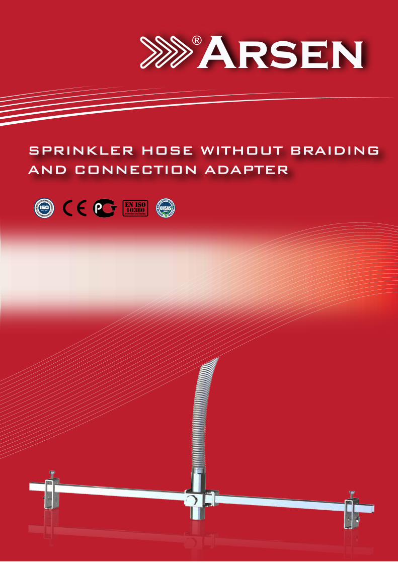
SPRINKLER HOSE WITHOUT BRAIDINGAND CONNECTION ADAPTER
Arsen
9001:2008ISOQ
UALI
TY MANAGEMENT SYSTEM
RE
GISTERED COMPA
NY
EN ISO10380
PRODUCED AND TESTED √18001OHSAS
CERTIFIED
HEALT
H & SAFETY MANAGEMENT SYSTEM
2
CONTENTS
CONTENTS 2
GENERAL EXPLANATIONS 3
GENERAL SPECIFICATIONS 4
Dimensions and Operating ConditionsMaterial SpecificationsFriction Losses and Specifications (UL Listed)
PRODUCT SPECIFICATIONS 5
Kit IntroductionCeiling SpecificationsSystem SpecificationsSafety Of Sprinkler Under Seismic Motions
TECHNICAL DRAWINGS 6
Kit Fixing Apparatus (Lay-in)Kit Fixing Apparatus (Clip-in)Hose Fixing ApparatusKit Suspension Profile
TECHNICAL DRAWINGS 7
DN20 Hose Technical DrawingDN25 Technical Drawing
NFPA 13 2007 EDITION 8
SOME TESTS PERFORMED AND CAUTION FOR INSTALLATION INSTRUCTIONS 9
Underwriters Laboratories (UL) Tarafından Yapılan Bazı TestlerCaution For Installation Instructions
INSTALLATION INSTRUCTIONS 10
Drawing - I and ExplanationsDrawing - II and ExplanationsDrawing - III and Explanations
INSTALLATION INSTRUCTIONS 11
Drawing - IV and ExplanationsDrawing - V and ExplanationsDrawing - VI and Explanations
INSTALLATION INSTRUCTIONS 12
Drawing - VII and ExplanationsDrawing - VIII and ExplanationsDrawing - IX and Explanations
CORRECT - INCORRECT INSTALLATIONS 13
3
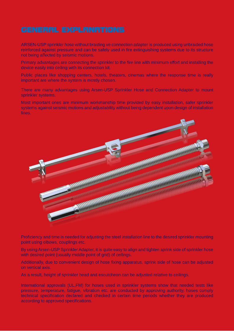
ARSEN-USP sprinkler hose without braiding ve connection adapter is produced using unbraided hose reinforced against pressure and can be safely used in fire extinguishing systems due to its structure not being affected by seismic motions.
Primary advantages are connecting the sprinkler to the fire line with minimum effort and installing the device easily into ceiling with its connection kit.
Public places like shopping centers, hotels, theaters, cinemas where the response time is really important are where the system is mostly chosen.
GENERAL EXPLANATIONS
There are many advantages using Arsen-USP Sprinkler Hose and Connection Adapter to mount sprinkler systems.
Most important ones are minimum workmanship time provided by easy installation, safer sprinkler systems against seismic motions and adjustability without being dependent upon design of installation lines.
International approvals (UL,FM) for hoses used in sprinkler systems show that needed tests like pressure, temperature, fatigue, vibration etc. are conducted by approving authority, hoses comply technical specification declared and checked in certain time periods whether they are produced according to approved specifications.
Proficiency and time is needed for adjusting the steel installation line to the desired sprinkler mounting point using elbows, couplings etc.
By using Arsen-USP Sprinkler Adapter, it is quite easy to align and tighten sprink side of sprinkler hose with desired point (usually middle point of grid) of ceilings.
Additionally, due to convenient design of hose fixing apparatus, sprink side of hose can be adjusted on vertical axis.
As a result, height of sprinkler head and escutcheon can be adjusted relative to ceilings.
4
GENERAL SPECIFICATIONS
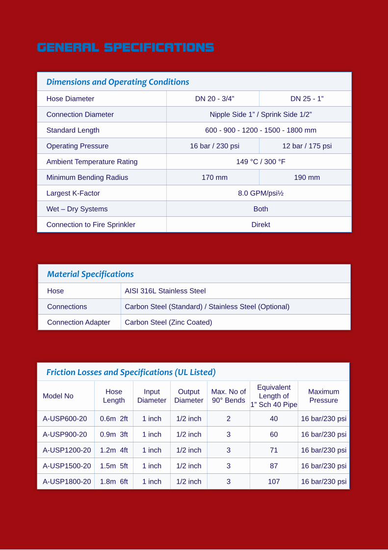
Dimensions and Operating Conditions
Hose Diameter DN 20 - 3/4” DN 25 - 1”
Connection Diameter Nipple Side 1” / Sprink Side 1/2”
Standard Length 600 - 900 - 1200 - 1500 - 1800 mm
Operating Pressure 16 bar / 230 psi 12 bar / 175 psi
Ambient Temperature Rating 149 °C / 300 °F
Minimum Bending Radius 170 mm 190 mm
Largest K-Factor 8.0 GPM/psi½
Wet – Dry Systems Both
Connection to Fire Sprinkler Direkt
Friction Losses and Specifications (UL Listed)
Model No HoseLength
InputDiameter
OutputDiameter
Max. No of90° Bends
Equivalent Length of
1” Sch 40 Pipe
MaximumPressure
A-USP600-20 0.6m 2ft 1 inch 1/2 inch 2 40 16 bar/230 psi
A-USP900-20 0.9m 3ft 1 inch 1/2 inch 3 60 16 bar/230 psi
A-USP1200-20 1.2m 4ft 1 inch 1/2 inch 3 71 16 bar/230 psi
A-USP1500-20 1.5m 5ft 1 inch 1/2 inch 3 87 16 bar/230 psi
A-USP1800-20 1.8m 6ft 1 inch 1/2 inch 3 107 16 bar/230 psi
Material Specifications
Hose AISI 316L Stainless Steel
Connections Carbon Steel (Standard) / Stainless Steel (Optional)
Connection Adapter Carbon Steel (Zinc Coated)
5
PRODUCT SPECIFICATIONS
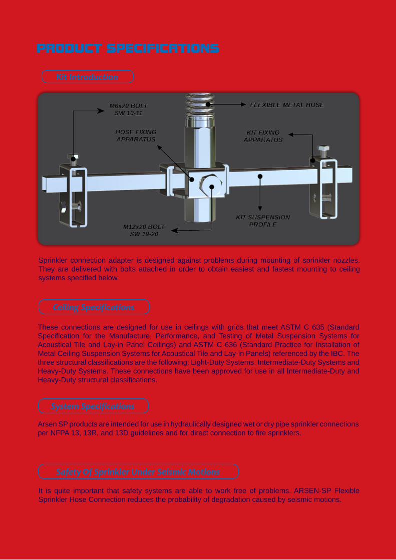
Sprinkler connection adapter is designed against problems during mounting of sprinkler nozzles. They are delivered with bolts attached in order to obtain easiest and fastest mounting to ceiling systems specified below.
These connections are designed for use in ceilings with grids that meet ASTM C 635 (Standard Specification for the Manufacture, Performance, and Testing of Metal Suspension Systems for Acoustical Tile and Lay-in Panel Ceilings) and ASTM C 636 (Standard Practice for Installation of Metal Ceiling Suspension Systems for Acoustical Tile and Lay-in Panels) referenced by the IBC. The three structural classifications are the following: Light-Duty Systems, Intermediate-Duty Systems and Heavy-Duty Systems. These connections have been approved for use in all Intermediate-Duty and Heavy-Duty structural classifications.
It is quite important that safety systems are able to work free of problems. ARSEN-SP Flexible Sprinkler Hose Connection reduces the probability of degradation caused by seismic motions.
Safety Of Sprinkler Under Seismic Motions
Ceiling Specifications
Kit Introduction
System Specifications
Arsen SP products are intended for use in hydraulically designed wet or dry pipe sprinkler connections per NFPA 13, 13R, and 13D guidelines and for direct connection to fire sprinklers.
6
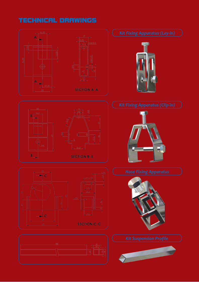
TECHNICAL DRAWINGS
Kit Fixing Apparatus (Lay-in)
Kit Fixing Apparatus (Clip-in)
Hose Fixing Apparatus
Kit Suspension Profile
7
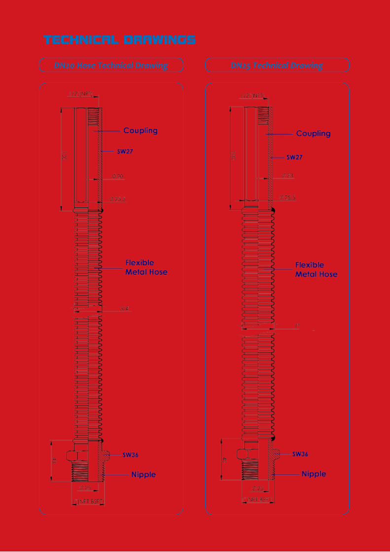
TECHNICAL DRAWINGS
DN20 Hose Technical Drawing DN25 Technical Drawing
8
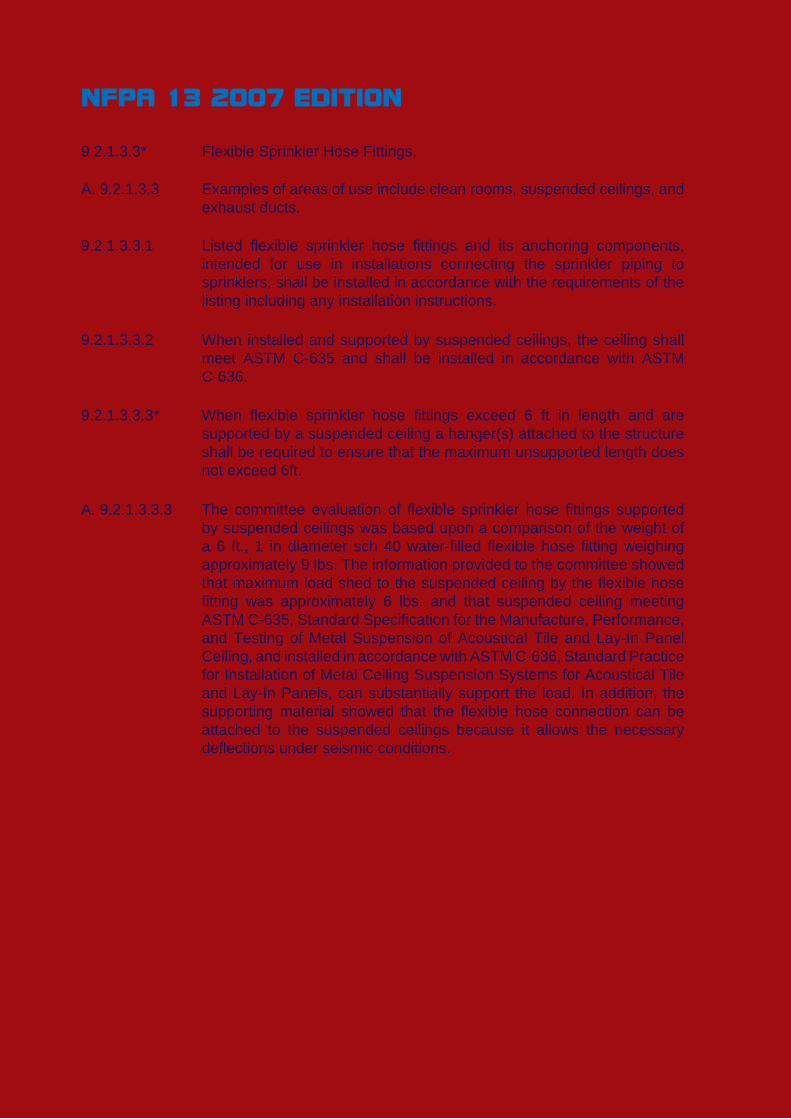
9.2.1.3.3* Flexible Sprinkler Hose Fittings.
A. 9.2.1.3.3 Examples of areas of use include clean rooms, suspended ceilings, and exhaust ducts.
9.2.1.3.3.1 Listed flexible sprinkler hose fittings and its anchoring components, intended for use in installations connecting the sprinkler piping to sprinklers, shall be installed in accordance with the requirements of the listing including any installation instructions.
9.2.1.3.3.2 When installed and supported by suspended ceilings, the ceiling shall meet ASTM C-635 and shall be installed in accordance with ASTM C-636.
9.2.1.3.3.3* When flexible sprinkler hose fittings exceed 6 ft in length and are supported by a suspended ceiling a hanger(s) attached to the structure shall be required to ensure that the maximum unsupported length does not exceed 6ft.
A. 9.2.1.3.3.3 The committee evaluation of flexible sprinkler hose fittings supported by suspended ceilings was based upon a comparison of the weight of a 6 ft., 1 in diameter sch 40 water-filled flexible hose fitting weighing approximately 9 lbs. The information provided to the committee showed that maximum load shed to the suspended ceiling by the flexible hose fitting was approximately 6 lbs. and that suspended ceiling meeting ASTM C-635, Standard Specification for the Manufacture, Performance, and Testing of Metal Suspension of Acoustical Tile and Lay-In Panel Ceiling, and installed in accordance with ASTM C-636, Standard Practice for Installation of Metal Ceiling Suspension Systems for Acoustical Tile and Lay-In Panels, can substantially support the load. In addition, the supporting material showed that the flexible hose connection can be attached to the suspended ceilings because it allows the necessary deflections under seismic conditions.
NFPA 13 2007 EDITION
9
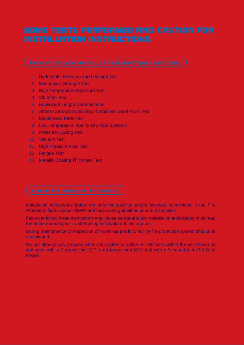
Underwriters Laboratories (UL) Tarafından Yapılan Bazı Testler
Caution For Installation Instructions
Installation instructions below are only for qualified and/or licensed technicians in the Fire Protection field. Consult NFPA and local code guidelines prior to installation.
Failure to follow these instructions may cause personal injury. Installation technicians must read the entire manual prior to attempting installation of this product.
During maintenance or inspection of Arsen-Sp product, facility fire protection system should be deactivated.
Do not attempt any process when the system is active. All M6 bolts within the set should be tightened with a 2 pound-foot (2.7 N.m) torque and M12 bolt with a 5 pound-foot (6.8 N.m) torque.
SOME TESTS PERFORMED AND CAUTION FOR INSTALLATION INSTRUCTIONS
1. Hydrostatic Pressure and Leakage Test2. Mechanical Strength Test3. High Temperature Exposure Test4. Vibration Test5. Equivalent Length Determination6. Stress-Corrosion Cracking of Stainless Steel Parts Test7. Elastomeric Parts Test8. Low Temperature Test for Dry Pipe Systems9. Pressure Cycling Test
10. Vacuum Test11. High Pressure Flow Test12. Fatigue Test13. Metallic Coating Thickness Test
10
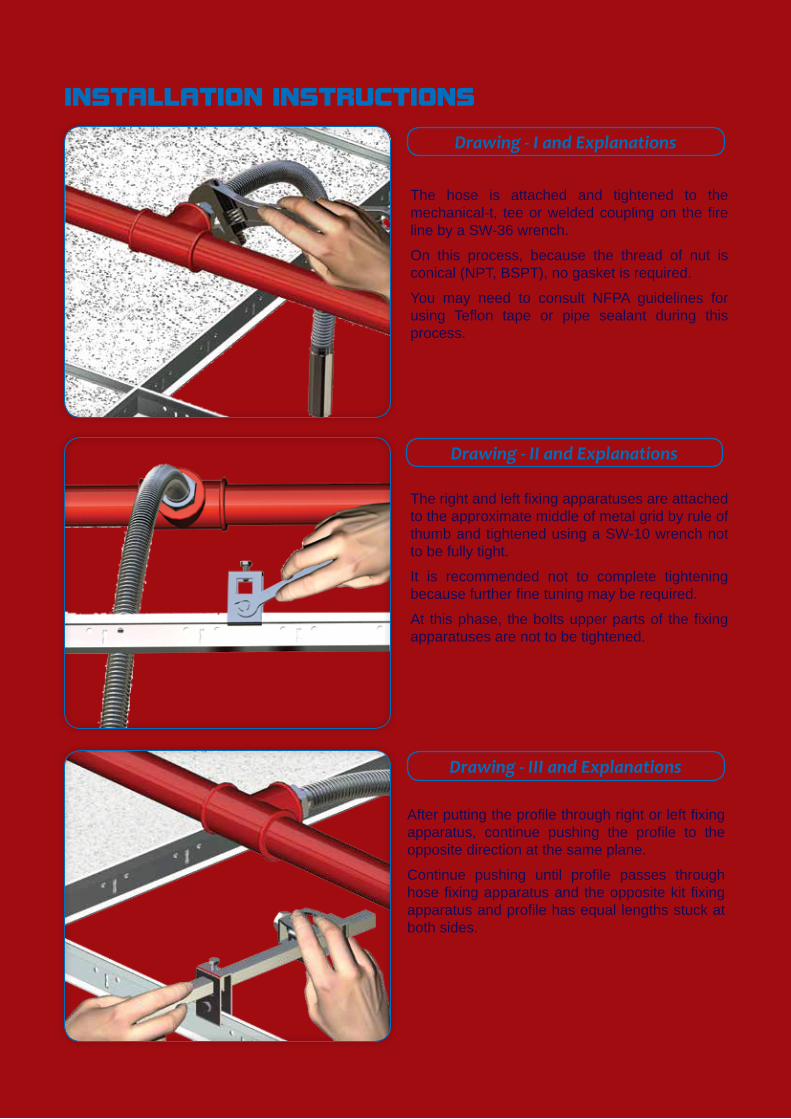
Drawing - I and Explanations
Drawing - II and Explanations
Drawing - III and Explanations
INSTALLATION INSTRUCTIONS
The hose is attached and tightened to the mechanical-t, tee or welded coupling on the fire line by a SW-36 wrench.
On this process, because the thread of nut is conical (NPT, BSPT), no gasket is required.
You may need to consult NFPA guidelines for using Teflon tape or pipe sealant during this process.
The right and left fixing apparatuses are attached to the approximate middle of metal grid by rule of thumb and tightened using a SW-10 wrench not to be fully tight.
It is recommended not to complete tightening because further fine tuning may be required.
At this phase, the bolts upper parts of the fixing apparatuses are not to be tightened.
After putting the profile through right or left fixing apparatus, continue pushing the profile to the opposite direction at the same plane.
Continue pushing until profile passes through hose fixing apparatus and the opposite kit fixing apparatus and profile has equal lengths stuck at both sides.
11
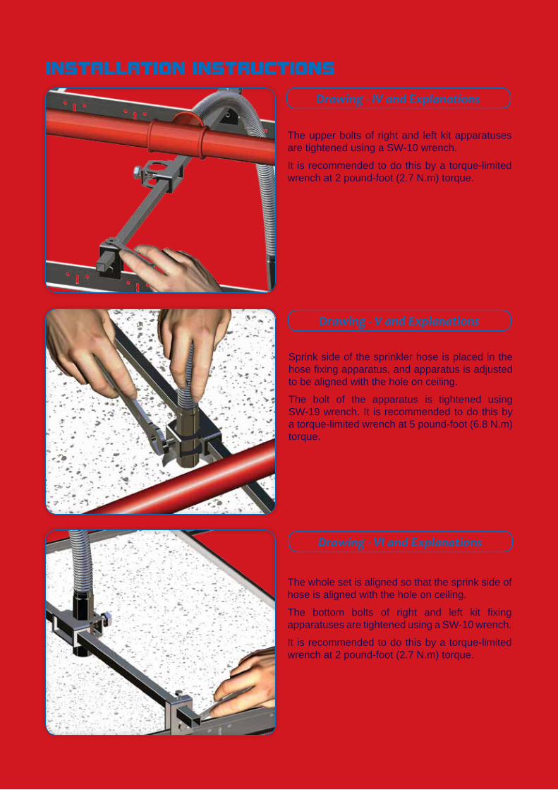
Drawing - IV and Explanations
Drawing - V and Explanations
Drawing - VI and Explanations
INSTALLATION INSTRUCTIONS
The upper bolts of right and left kit apparatuses are tightened using a SW-10 wrench.
It is recommended to do this by a torque-limited wrench at 2 pound-foot (2.7 N.m) torque.
Sprink side of the sprinkler hose is placed in the hose fixing apparatus, and apparatus is adjusted to be aligned with the hole on ceiling.
The bolt of the apparatus is tightened using SW-19 wrench. It is recommended to do this by a torque-limited wrench at 5 pound-foot (6.8 N.m) torque.
The whole set is aligned so that the sprink side of hose is aligned with the hole on ceiling.
The bottom bolts of right and left kit fixing apparatuses are tightened using a SW-10 wrench.
It is recommended to do this by a torque-limited wrench at 2 pound-foot (2.7 N.m) torque.
12
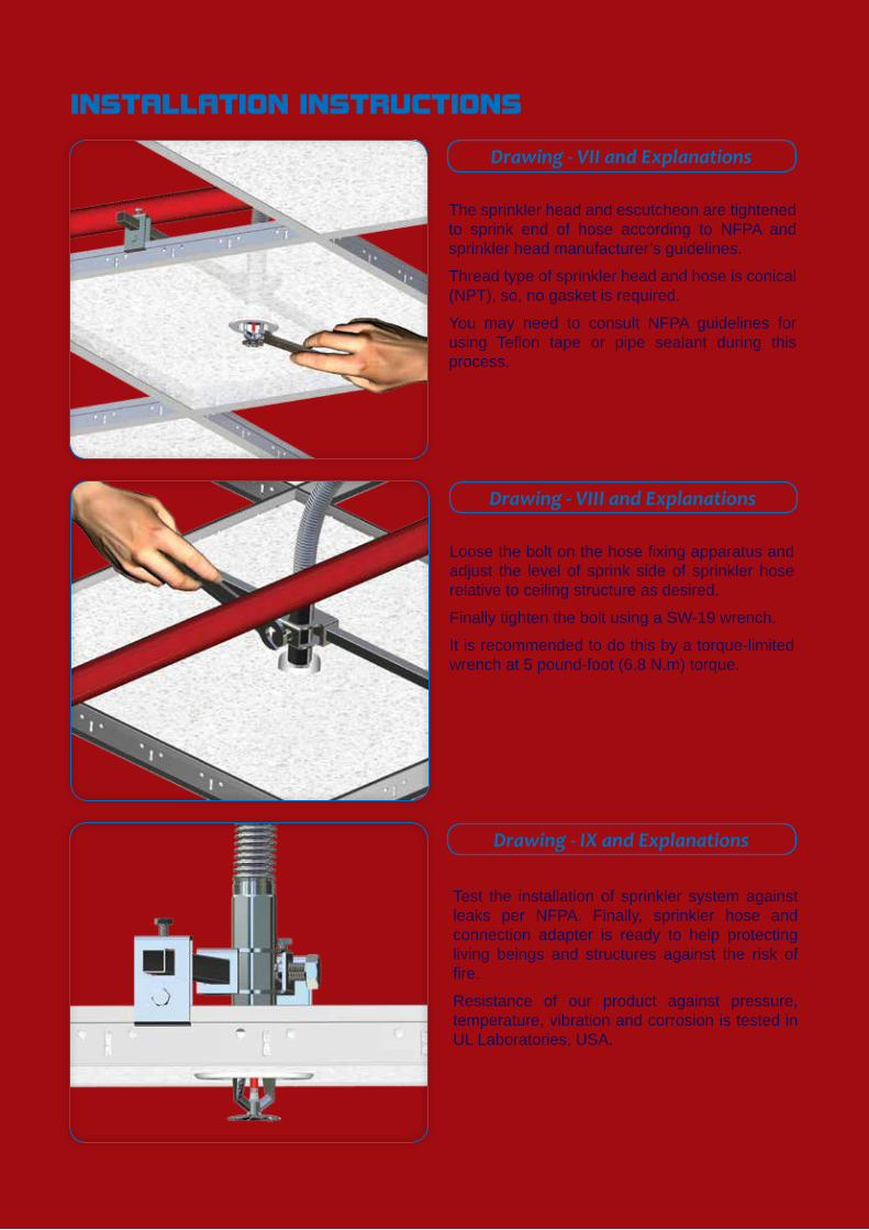
Drawing - VII and Explanations
Drawing - VIII and Explanations
Drawing - IX and Explanations
INSTALLATION INSTRUCTIONS
The sprinkler head and escutcheon are tightened to sprink end of hose according to NFPA and sprinkler head manufacturer’s guidelines.
Thread type of sprinkler head and hose is conical (NPT), so, no gasket is required.
You may need to consult NFPA guidelines for using Teflon tape or pipe sealant during this process.
Loose the bolt on the hose fixing apparatus and adjust the level of sprink side of sprinkler hose relative to ceiling structure as desired.
Finally tighten the bolt using a SW-19 wrench.
It is recommended to do this by a torque-limited wrench at 5 pound-foot (6.8 N.m) torque.
Test the installation of sprinkler system against leaks per NFPA. Finally, sprinkler hose and connection adapter is ready to help protecting living beings and structures against the risk of fire.
Resistance of our product against pressure, temperature, vibration and corrosion is tested in UL Laboratories, USA.
13
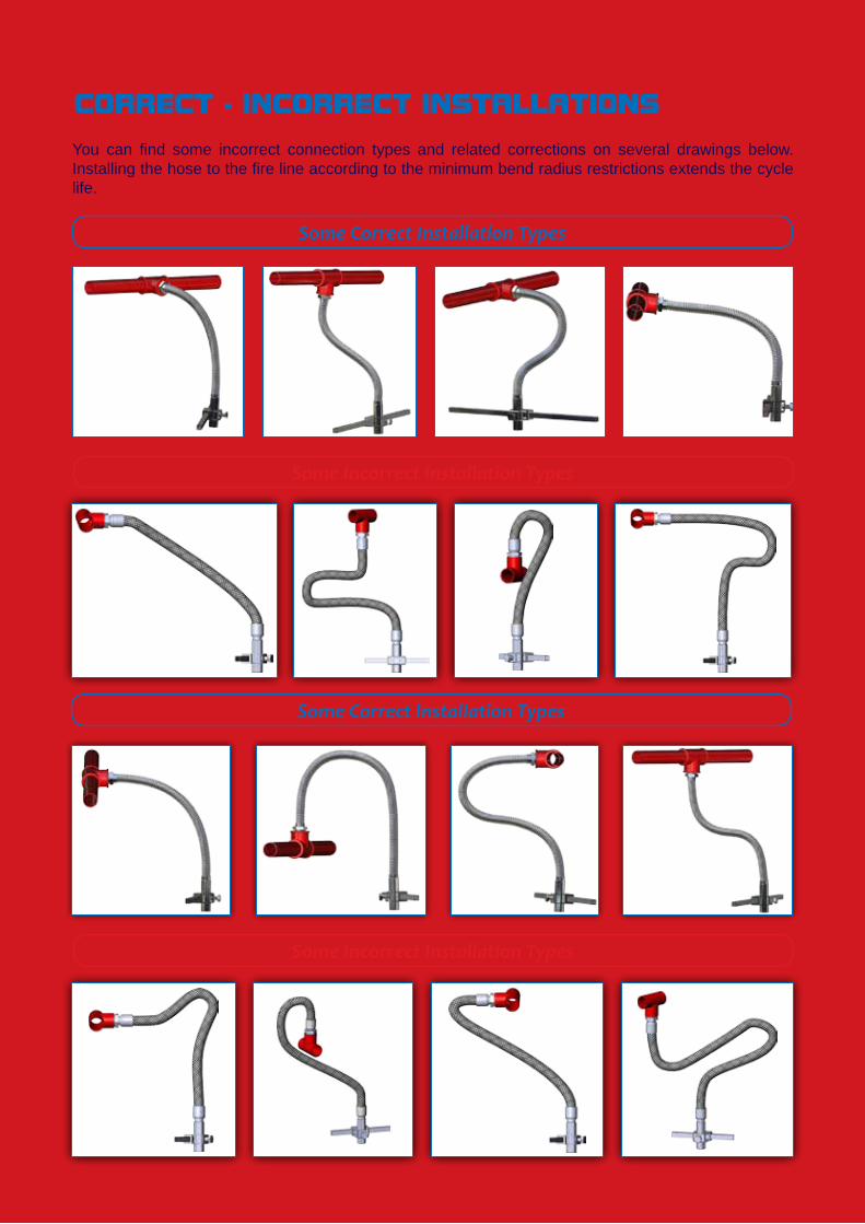
Some Correct Installation Types
Some Incorrect Installation Types
Some Correct Installation Types
Some Incorrect Installation Types
CORRECT - INCORRECT INSTALLATIONS
You can find some incorrect connection types and related corrections on several drawings below. Installing the hose to the fire line according to the minimum bend radius restrictions extends the cycle life.
Arsen Industrial InstallationProducts Ltd.Co.Address : Merkez Mah. Emirler Sok. No:2534245 Gaziosmanpasa/Istanbul-TurkiyeTel : +90 212 564 90 40 Fax :+90 212 564 90 88Web : www.arsen.com.trEmail : [email protected]
“QUALITY ALWAYS WINS”
Arsenflex
![[Bruce Grant] Leather Braiding(Bookos.org)](https://static.fdocuments.net/doc/165x107/545e79d2af79592b708b4819/bruce-grant-leather-braidingbookosorg.jpg)