
SPRING LOADED DEVICES - Jergens · PDF fileSPRING LOADED DEVICES SPRING LOADED DEVICES Spring...
18
33 SPRING LOADED DEVICES SPRING LOADED DEVICES Spring Loaded Devices Plungers: Plungers, Spring .......................................................36–37 Plungers, Spring, Metric..........................................38–39 Plungers, Shortie Spring ............................................... 40 Plungers, Shortie Spring Stainless Steel .............................................................. 40 Plungers, Shortie Spring, Metric ................................. 41 Ball Plungers.................................................................... 42 Ball Plungers, Stainless Steel........................................ 43 Ball Plungers, Metric ...................................................... 43 Plungers, Press Fit .......................................................... 43 Plungers, Special Spring and Ball................................ 44 Plungers, Hand Retractable Style ............................... 45 Plungers, Pull Ring Retractable ................................... 46 Plungers, L Handle Hand Retractable Locking ................................................... 47 Plunger Wrenches .......................................................... 41 Quick Reference Index .................................................. 35 Spring Locating Pins ............................................... 48–49 Application Ideas......................................................... 49 Installation Data ............................................................. 49 Installation Tools ............................................................ 49 Eccentric Liners ............................................................... 49 Spring Stops .................................................................... 50 Button Type .................................................................. 50 Flat Button Type .......................................................... 50 Tang Type ...................................................................... 50
Transcript of SPRING LOADED DEVICES - Jergens · PDF fileSPRING LOADED DEVICES SPRING LOADED DEVICES Spring...
33
SP
RIN
G L
OA
DE
D D
EV
ICE
S
SPRING LOADED DEVICES
Spring Loaded Devices
Plungers:Plungers, Spring .......................................................36–37Plungers, Spring, Metric ..........................................38–39Plungers, Shortie Spring ............................................... 40Plungers, Shortie Spring
Stainless Steel .............................................................. 40Plungers, Shortie Spring, Metric ................................. 41Ball Plungers .................................................................... 42Ball Plungers, Stainless Steel........................................ 43Ball Plungers, Metric ...................................................... 43Plungers, Press Fit .......................................................... 43Plungers, Special Spring and Ball ................................ 44Plungers, Hand Retractable Style ............................... 45Plungers, Pull Ring Retractable ................................... 46Plungers, L Handle Hand
Retractable Locking ................................................... 47Plunger Wrenches .......................................................... 41Quick Reference Index .................................................. 35Spring Locating Pins ............................................... 48–49
Application Ideas ......................................................... 49Installation Data ............................................................. 49Installation Tools ............................................................ 49Eccentric Liners ............................................................... 49Spring Stops .................................................................... 50
Button Type .................................................................. 50Flat Button Type .......................................................... 50Tang Type ...................................................................... 50
Jergens, Inc. | 15700 S. Waterloo Road | Cleveland, Ohio 44110-3898 USA34
S P E C I A LT Y F A S T E N E R S G R O U P
SPRING LOADED DEVICES
SP
RIN
G L
OA
DE
D D
EV
ICE
S
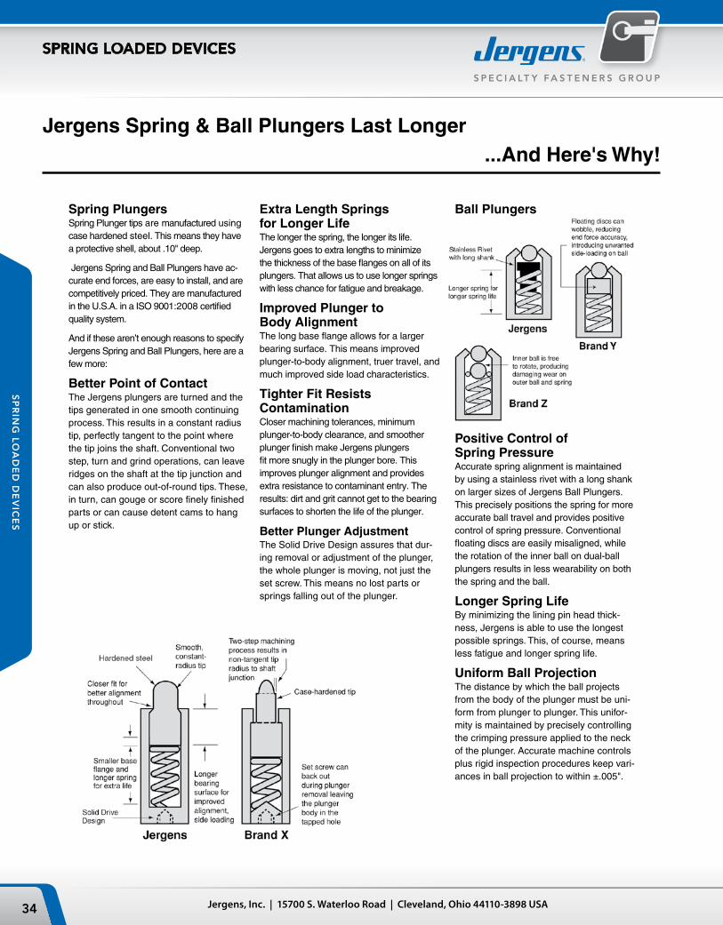
Spring PlungersSpring Plunger tips are manufactured using case hardened steel. This means they have a protective shell, about .10" deep.
Jergens Spring and Ball Plungers have ac-curate end forces, are easy to install, and are competitively priced. They are manufactured in the U.S.A. in a ISO 9001:2008 certified quality system.
And if these aren’t enough reasons to specify Jergens Spring and Ball Plungers, here are a few more:
Better Point of ContactThe Jergens plungers are turned and the tips generated in one smooth continuing process. This results in a constant radius tip, perfectly tangent to the point where the tip joins the shaft. Conventional two step, turn and grind operations, can leave ridges on the shaft at the tip junction and can also produce out-of-round tips. These, in turn, can gouge or score finely finished parts or can cause detent cams to hang up or stick.
Extra Length Springs for Longer LifeThe longer the spring, the longer its life. Jergens goes to extra lengths to minimize the thickness of the base flanges on all of its plungers. That allows us to use longer springs with less chance for fatigue and breakage.
Improved Plunger to Body AlignmentThe long base flange allows for a larger bearing surface. This means improved plunger-to-body alignment, truer travel, and much improved side load characteristics.
Tighter Fit Resists ContaminationCloser machining tolerances, minimum plunger-to-body clearance, and smoother plunger finish make Jergens plungers fit more snugly in the plunger bore. This improves plunger alignment and provides extra resistance to contaminant entry. The results: dirt and grit cannot get to the bearing surfaces to shorten the life of the plunger.
Better Plunger AdjustmentThe Solid Drive Design assures that dur-ing removal or adjustment of the plunger, the whole plunger is moving, not just the set screw. This means no lost parts or springs falling out of the plunger.
Jergens Spring & Ball Plungers Last Longer
Ball Plungers
Positive Control of Spring PressureAccurate spring alignment is maintained by using a stainless rivet with a long shank on larger sizes of Jergens Ball Plungers. This precisely positions the spring for more accurate ball travel and provides positive control of spring pressure. Conventional floating discs are easily misaligned, while the rotation of the inner ball on dual-ball plungers results in less wearability on both the spring and the ball.
Longer Spring LifeBy minimizing the lining pin head thick-ness, Jergens is able to use the longest possible springs. This, of course, means less fatigue and longer spring life.
Uniform Ball ProjectionThe distance by which the ball projects from the body of the plunger must be uni-form from plunger to plunger. This unifor-mity is maintained by precisely controlling the crimping pressure applied to the neck of the plunger. Accurate machine controls plus rigid inspection procedures keep vari-ances in ball projection to within ±.005".
...And Here's Why!
35Phone: 866-KWIK-LOK (594-5565) | Fax: +1 216-481-6193 | E-mail: [email protected] | www.jergensinc.com
S P E C I A LT Y FA S T E N E R S G R O U P
SPRING LOADED DEVICES
SP
RIN
G L
OA
DE
D D
EV
ICE
S
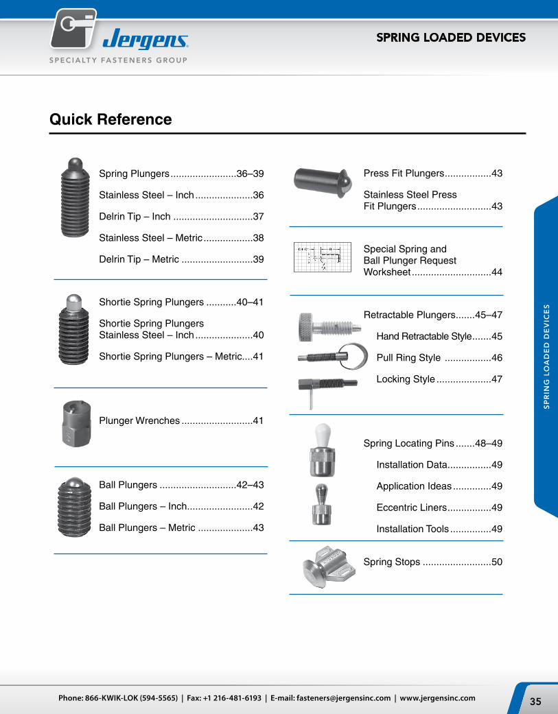
Spring Plungers ........................36–39
Stainless Steel – Inch .....................36
Delrin Tip – Inch .............................37
Stainless Steel – Metric ..................38
Delrin Tip – Metric ..........................39
Shortie Spring Plungers ...........40–41
Shortie Spring Plungers Stainless Steel – Inch .....................40
Shortie Spring Plungers – Metric....41
Plunger Wrenches ..........................41
Ball Plungers ............................42–43
Ball Plungers – Inch ........................42
Ball Plungers – Metric ....................43
Quick Reference
Press Fit Plungers .................43
Stainless Steel Press Fit Plungers ...........................43
Special Spring and Ball Plunger Request Worksheet .............................44
Retractable Plungers .......45–47
Hand Retractable Style .......45
Pull Ring Style .................46
Locking Style ....................47
Spring Locating Pins .......48–49
Installation Data................49
Application Ideas ..............49
Eccentric Liners ................49
Installation Tools ...............49
Spring Stops .........................50
Jergens, Inc. | 15700 S. Waterloo Road | Cleveland, Ohio 44110-3898 USA36
S P E C I A LT Y F A S T E N E R S G R O U P
SPRING LOADED DEVICES
SP
RIN
G L
OA
DE
D D
EV
ICE
S
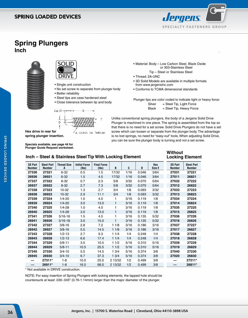
Spring PlungersInch
•Singleunitconstruction•Nosetscrewtoseparatefromplungerbody•Betterreliability•Steeltipsarecasehardenedsteel•Closetolerancebetweentipandbody
Unlike conventional spring plungers, the body of a Jergens Solid Drive Plunger is machined in one piece. The spring is assembled from the top so that there is no need for a set screw. Solid Drive Plungers do not have a set screw which can loosen or separate from the plunger body. The advantage is no lost springs, no need for “easy-out” tools. When adjusting Solid Drive, you can be sure the plunger body is turning and not a set screw.
•Material: Body – Low Carbon Steel, Black Oxide or 303-Stainless Steel
Tip – Steel or Stainless Steel•Thread: 2A-UNC•3D Solid Models are available in multiple formats
from www.jergensinc.com•Conforms to TCMA dimensional standards
Hex drive in rear for spring plunger insertion.
Inch – Steel & Stainless Steel Tip With Locking ElementWithout Locking Element
SS Part Steel Part Thread Size Initial Force Final Force Hex SS Part Steel Part Number Number A (lbs) (lbs) B C D Size E Number Number
27336 27321 6-32 0.5 1.5 17/32 1/16 0.046 3/64 27031 27221 26936 26921 6-32 1.5 4.5 17/32 1/16 0.046 3/64 27011 26821 27337 27322 8-32 0.7 2.3 5/8 3/32 0.070 5/64 27032 27222 26937 26922 8-32 2.7 7.3 5/8 3/32 0.070 5/64 27012 26822 27338 27323 10-32 1.3 2.7 3/4 1/8 0.093 3/32 27033 27223 26938 26923 10-32 2.9 11.1 3/4 1/8 0.093 3/32 27013 26823 27339 27324 1/4-20 1.0 4.0 1 3/16 0.119 1/8 27034 27224 26939 26924 1/4-20 3.0 13.0 1 3/16 0.119 1/8 27014 26824 27340 27325 1/4-28 1.0 4.0 1 3/16 0.119 1/8 27035 27225 26940 26925 1/4-28 3.0 13.0 1 3/16 0.119 1/8 27015 26825 27341 27326 5/16-18 1.5 4.5 1 3/16 0.135 5/32 27036 27226 26941 26926 5/16-18 3.0 15.0 1 3/16 0.135 5/32 27016 26826 27342 27327 3/8-16 2.8 7.2 1 1/8 3/16 0.186 3/16 27037 27227 26942 26927 3/8-16 5.5 14.5 1 1/8 3/16 0.186 3/16 27017 26827 27343 27328 1/2-13 2.7 9.3 1 1/4 1/4 0.248 1/4 27038 27228 26943 26928 1/2-13 6.6 17.4 1 1/4 1/4 0.248 1/4 27018 26828 27344 27329 5/8-11 3.5 10.5 1 1/2 5/16 0.310 5/16 27039 27229 26944 26929 5/8-11 10.5 25.5 1 1/2 5/16 0.310 5/16 27019 26829 27345 27330 3/4-10 5.5 14.5 1 3/4 5/16 0.374 3/8 27040 27230 26945 26930 3/4-10 6.7 37.3 1 3/4 5/16 0.374 3/8 27020 26830 — 27311* 1-8 10.0 25.0 2 13/32 1/2 0.499 3/8 — 27211* — 26911* 1-8 16.0 68.0 2 13/32 1/2 0.499 3/8 — 26811** Not available in DRIVE construction.
NOTE: For easy insertion of Spring Plungers with locking elements, the tapped hole should be countersunk at least .030-.045" (0.76-1.14mm) larger than the major diameter of the plunger.
Plunger tips are color coded to indicate light or heavy force: Silver = Steel Tip, Light Force Black = Steel Tip, Heavy Force
Specials available, see page 44 for Plunger Quote Request worksheet.
37Phone: 866-KWIK-LOK (594-5565) | Fax: +1 216-481-6193 | E-mail: [email protected] | www.jergensinc.com
S P E C I A LT Y FA S T E N E R S G R O U P
SPRING LOADED DEVICES
SP
RIN
G L
OA
DE
D D
EV
ICE
S
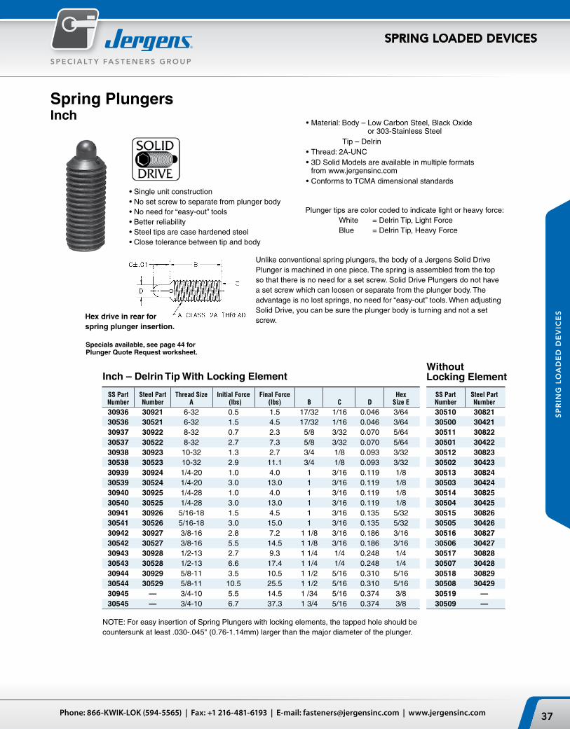
•Singleunitconstruction•Nosetscrewtoseparatefromplungerbody•Noneedfor“easy-out”tools•Betterreliability•Steeltipsarecasehardenedsteel•Closetolerancebetweentipandbody
Hex drive in rear for spring plunger insertion.
Plunger tips are color coded to indicate light or heavy force: White = Delrin Tip, Light Force Blue = Delrin Tip, Heavy Force
SS Part Steel Part Thread Size Initial Force Final Force Hex SS Part Steel Part Number Number A (lbs) (lbs) B C D Size E Number Number
30936 30921 6-32 0.5 1.5 17/32 1/16 0.046 3/64 30510 30821 30536 30521 6-32 1.5 4.5 17/32 1/16 0.046 3/64 30500 30421 30937 30922 8-32 0.7 2.3 5/8 3/32 0.070 5/64 30511 30822 30537 30522 8-32 2.7 7.3 5/8 3/32 0.070 5/64 30501 30422 30938 30923 10-32 1.3 2.7 3/4 1/8 0.093 3/32 30512 30823 30538 30523 10-32 2.9 11.1 3/4 1/8 0.093 3/32 30502 30423 30939 30924 1/4-20 1.0 4.0 1 3/16 0.119 1/8 30513 30824 30539 30524 1/4-20 3.0 13.0 1 3/16 0.119 1/8 30503 30424 30940 30925 1/4-28 1.0 4.0 1 3/16 0.119 1/8 30514 30825 30540 30525 1/4-28 3.0 13.0 1 3/16 0.119 1/8 30504 30425 30941 30926 5/16-18 1.5 4.5 1 3/16 0.135 5/32 30515 30826 30541 30526 5/16-18 3.0 15.0 1 3/16 0.135 5/32 30505 30426 30942 30927 3/8-16 2.8 7.2 1 1/8 3/16 0.186 3/16 30516 30827 30542 30527 3/8-16 5.5 14.5 1 1/8 3/16 0.186 3/16 30506 30427 30943 30928 1/2-13 2.7 9.3 1 1/4 1/4 0.248 1/4 30517 30828 30543 30528 1/2-13 6.6 17.4 1 1/4 1/4 0.248 1/4 30507 30428 30944 30929 5/8-11 3.5 10.5 1 1/2 5/16 0.310 5/16 30518 30829 30544 30529 5/8-11 10.5 25.5 1 1/2 5/16 0.310 5/16 30508 30429 30945 — 3/4-10 5.5 14.5 1 /34 5/16 0.374 3/8 30519 — 30545 — 3/4-10 6.7 37.3 1 3/4 5/16 0.374 3/8 30509 —
Inch – Delrin Tip With Locking ElementWithout Locking Element
Spring PlungersInch
Unlike conventional spring plungers, the body of a Jergens Solid Drive Plunger is machined in one piece. The spring is assembled from the top so that there is no need for a set screw. Solid Drive Plungers do not have a set screw which can loosen or separate from the plunger body. The advantage is no lost springs, no need for “easy-out” tools. When adjusting Solid Drive, you can be sure the plunger body is turning and not a set screw.
•Material: Body – Low Carbon Steel, Black Oxide or 303-Stainless Steel
Tip – Delrin•Thread: 2A-UNC •3D Solid Models are available in multiple formats
from www.jergensinc.com•Conforms to TCMA dimensional standards
NOTE: For easy insertion of Spring Plungers with locking elements, the tapped hole should be countersunk at least .030-.045" (0.76-1.14mm) larger than the major diameter of the plunger.
Specials available, see page 44 for Plunger Quote Request worksheet.
Jergens, Inc. | 15700 S. Waterloo Road | Cleveland, Ohio 44110-3898 USA38
S P E C I A LT Y F A S T E N E R S G R O U P
SPRING LOADED DEVICES
SP
RIN
G L
OA
DE
D D
EV
ICE
S
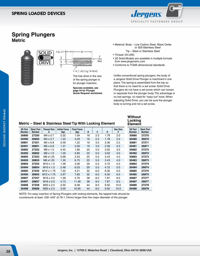
Metric – Steel & Stainless Steel Tip With Locking Element
SS Part Steel Part Thread Size Initial Force Final Force Hex Size SS Part Steel Part Number Number A (kg) (kg) B C D E Number Number
30890 27250 M4 x 0.7 0.32 1.04 16 2.5 1.78 2.0 30880 27270 30490 26850 M4 x 0.7 1.22 3.29 16 2.5 1.78 2.0 30480 26870 30891 27251 M5 x 0.8 0.59 1.22 19 3.0 2.36 2.5 30881 27271 30491 26851 M5 x 0.8 1.31 5.00 19 3.0 2.36 2.5 30481 26871 30892 27252 M6 x 1.0 0.45 1.80 25 5.0 3.02 3.0 30882 27272 30492 26852 M6 x 1.0 1.35 5.85 25 5.0 3.02 3.0 30482 26872 30893 27253 M8 x1.25 0.68 2.03 25 5.0 3.43 4.0 30883 27273 30493 26853 M8 x1.25 1.35 6.75 25 5.0 3.43 4.0 30483 26873 30894 27254 M10 x 1.5 1.26 3.26 29 5.0 4.72 5.0 30884 27274 30494 26854 M10 x 1.5 2.48 6.53 29 5.0 4.72 5.0 30484 26874 30895 27255 M12 x 1.75 1.22 4.21 32 6.0 6.30 6.0 30885 27275 30495 26855 M12 x 1.75 2.97 7.83 32 6.0 6.30 6.0 30485 26875 30897 27257 M16 x 2.0 1.58 4.76 38 8.0 7.87 8.0 30887 27277 30497 26857 M16 x 2.0 4.73 11.48 38 8.0 7.87 8.0 30487 26877 30898 27258 M20 x 2.5 2.50 6.58 44 8.0 9.50 10.0 30888 27278 30498 26858 M20 x 2.5 3.05 16.95 44 8.0 9.50 10.0 30488 26878
Without Locking Element
Spring PlungersMetric
The hex drive in the rear of the spring plunger is for plunger insertion.
Specials available, see page 44 for Plunger Quote Request worksheet.
Unlike conventional spring plungers, the body of a Jergens Solid Drive Plunger is machined in one piece. The spring is assembled from the top so that there is no need for a set screw. Solid Drive Plungers do not have a set screw which can loosen or separate from the plunger body. The advantage is no lost springs, no need for “easy-out” tools. When adjusting Solid Drive, you can be sure the plunger body is turning and not a set screw.
•Material: Body – Low Carbon Steel, Black Oxide or 303-Stainless Steel
Tip – Steel or Stainless Steel•Thread: 2A-UNC •3D Solid Models are available in multiple formats
from www.jergensinc.com•Conforms to TCMA dimensional standards
NOTE: For easy insertion of Spring Plungers with locking elements, the tapped hole should be countersunk at least .030-.045" (0.76-1.14mm) larger than the major diameter of the plunger.
39Phone: 866-KWIK-LOK (594-5565) | Fax: +1 216-481-6193 | E-mail: [email protected] | www.jergensinc.com
S P E C I A LT Y FA S T E N E R S G R O U P
SPRING LOADED DEVICES
SP
RIN
G L
OA
DE
D D
EV
ICE
S
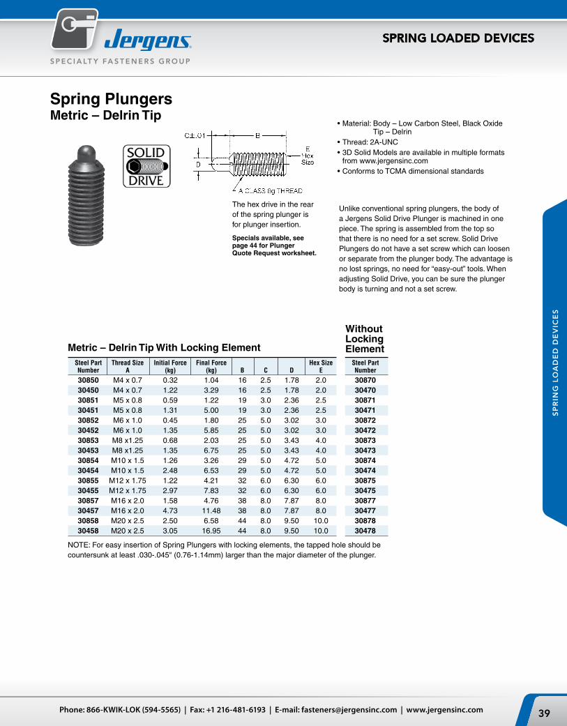
Spring PlungersMetric – Delrin Tip
The hex drive in the rear of the spring plunger is for plunger insertion.
Specials available, see page 44 for Plunger Quote Request worksheet.
Steel Part Thread Size Initial Force Final Force Hex Size Steel Part Number A (kg) (kg) B C D E Number
30850 M4 x 0.7 0.32 1.04 16 2.5 1.78 2.0 30870 30450 M4 x 0.7 1.22 3.29 16 2.5 1.78 2.0 30470 30851 M5 x 0.8 0.59 1.22 19 3.0 2.36 2.5 30871 30451 M5 x 0.8 1.31 5.00 19 3.0 2.36 2.5 30471 30852 M6 x 1.0 0.45 1.80 25 5.0 3.02 3.0 30872 30452 M6 x 1.0 1.35 5.85 25 5.0 3.02 3.0 30472 30853 M8 x1.25 0.68 2.03 25 5.0 3.43 4.0 30873 30453 M8 x1.25 1.35 6.75 25 5.0 3.43 4.0 30473 30854 M10 x 1.5 1.26 3.26 29 5.0 4.72 5.0 30874 30454 M10 x 1.5 2.48 6.53 29 5.0 4.72 5.0 30474 30855 M12 x 1.75 1.22 4.21 32 6.0 6.30 6.0 30875 30455 M12 x 1.75 2.97 7.83 32 6.0 6.30 6.0 30475 30857 M16 x 2.0 1.58 4.76 38 8.0 7.87 8.0 30877 30457 M16 x 2.0 4.73 11.48 38 8.0 7.87 8.0 30477 30858 M20 x 2.5 2.50 6.58 44 8.0 9.50 10.0 30878 30458 M20 x 2.5 3.05 16.95 44 8.0 9.50 10.0 30478
Metric – Delrin Tip With Locking Element
Without Locking Element
Unlike conventional spring plungers, the body of a Jergens Solid Drive Plunger is machined in one piece. The spring is assembled from the top so that there is no need for a set screw. Solid Drive Plungers do not have a set screw which can loosen or separate from the plunger body. The advantage is no lost springs, no need for “easy-out” tools. When adjusting Solid Drive, you can be sure the plunger body is turning and not a set screw.
•Material: Body – Low Carbon Steel, Black Oxide Tip – Delrin
•Thread: 2A-UNC •3D Solid Models are available in multiple formats
from www.jergensinc.com•Conforms to TCMA dimensional standards
NOTE: For easy insertion of Spring Plungers with locking elements, the tapped hole should be countersunk at least .030-.045" (0.76-1.14mm) larger than the major diameter of the plunger.
Jergens, Inc. | 15700 S. Waterloo Road | Cleveland, Ohio 44110-3898 USA40
S P E C I A LT Y F A S T E N E R S G R O U P
SPRING LOADED DEVICES
SP
RIN
G L
OA
DE
D D
EV
ICE
S
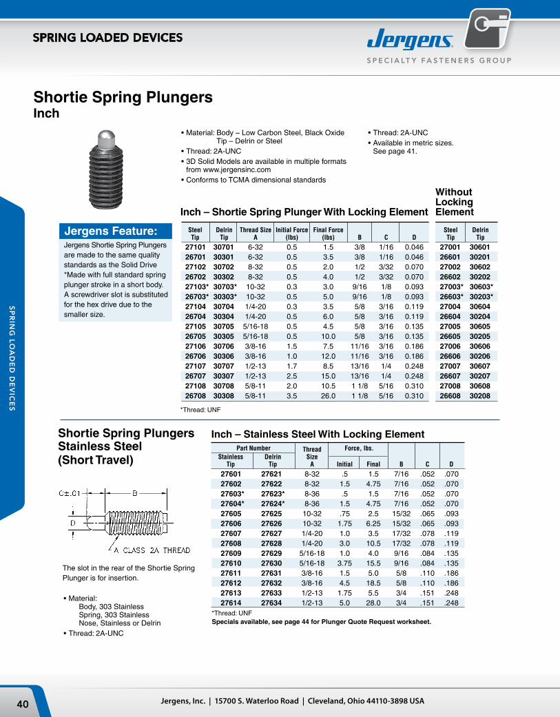
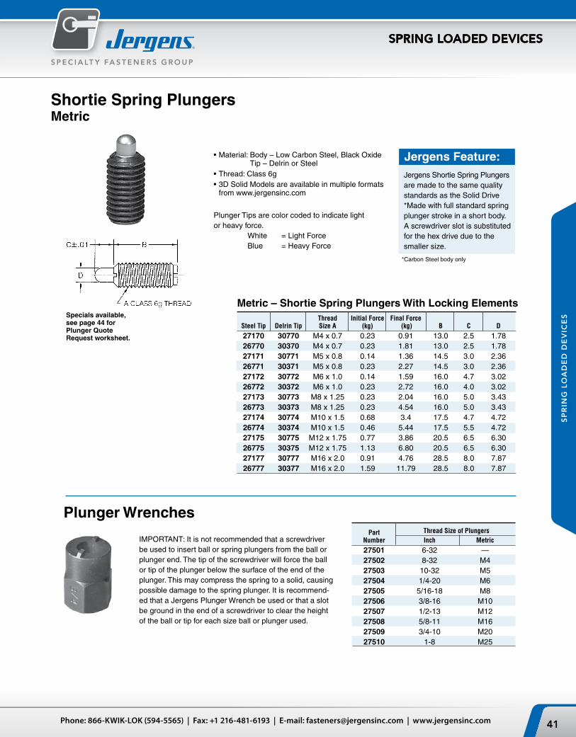
Shortie Spring PlungersInch
The slot in the rear of the Shortie Spring Plunger is for insertion.
Shortie Spring Plungers Stainless Steel(Short Travel)
•Thread: 2A-UNC•Available in metric sizes.
See page 41.
•Ma terial: Body, 303 Stainless Spring, 303 Stainless Nose, Stainless or Delrin
•Thread: 2A-UNC
Jergens Feature:Jergens Shortie Spring Plungers are made to the same quality standards as the Solid Drive *Made with full standard spring plunger stroke in a short body. A screwdriver slot is substituted for the hex drive due to the smaller size.
Inch – Shortie Spring Plunger With Locking Element
Without Locking Element
Steel Delrin Thread Size Initial Force Final Force Steel Delrin Tip Tip A (lbs) (lbs) B C D Tip Tip
27101 30701 6-32 0.5 1.5 3/8 1/16 0.046 27001 30601 26701 30301 6-32 0.5 3.5 3/8 1/16 0.046 26601 30201 27102 30702 8-32 0.5 2.0 1/2 3/32 0.070 27002 30602 26702 30302 8-32 0.5 4.0 1/2 3/32 0.070 26602 30202 27103* 30703* 10-32 0.3 3.0 9/16 1/8 0.093 27003* 30603* 26703* 30303* 10-32 0.5 5.0 9/16 1/8 0.093 26603* 30203* 27104 30704 1/4-20 0.3 3.5 5/8 3/16 0.119 27004 30604 26704 30304 1/4-20 0.5 6.0 5/8 3/16 0.119 26604 30204 27105 30705 5/16-18 0.5 4.5 5/8 3/16 0.135 27005 30605 26705 30305 5/16-18 0.5 10.0 5/8 3/16 0.135 26605 30205 27106 30706 3/8-16 1.5 7.5 11/16 3/16 0.186 27006 30606 26706 30306 3/8-16 1.0 12.0 11/16 3/16 0.186 26606 30206 27107 30707 1/2-13 1.7 8.5 13/16 1/4 0.248 27007 30607 26707 30307 1/2-13 2.5 15.0 13/16 1/4 0.248 26607 30207 27108 30708 5/8-11 2.0 10.5 1 1/8 5/16 0.310 27008 30608 26708 30308 5/8-11 3.5 26.0 1 1/8 5/16 0.310 26608 30208
*Thread: UNF
Inch – Stainless Steel With Locking Element Part Number Thread Force, lbs. Stainless Delrin Size Tip Tip A Initial Final B C D
27601 27621 8-32 .5 1.5 7/16 .052 .070 27602 27622 8-32 1.5 4.75 7/16 .052 .070 27603* 27623* 8-36 .5 1.5 7/16 .052 .070 27604* 27624* 8-36 1.5 4.75 7/16 .052 .070 27605 27625 10-32 .75 2.5 15/32 .065 .093 27606 27626 10-32 1.75 6.25 15/32 .065 .093 27607 27627 1/4-20 1.0 3.5 17/32 .078 .119 27608 27628 1/4-20 3.0 10.5 17/32 .078 .119 27609 27629 5/16-18 1.0 4.0 9/16 .084 .135 27610 27630 5/16-18 3.75 15.5 9/16 .084 .135 27611 27631 3/8-16 1.5 5.0 5/8 .110 .186 27612 27632 3/8-16 4.5 18.5 5/8 .110 .186 27613 27633 1/2-13 1.75 5.5 3/4 .151 .248 27614 27634 1/2-13 5.0 28.0 3/4 .151 .248*Thread: UNF
•Material: Body – Low Carbon Steel, Black Oxide Tip – Delrin or Steel
•Thread: 2A-UNC •3D Solid Models are available in multiple formats
from www.jergensinc.com•Conforms to TCMA dimensional standards
Specials available, see page 44 for Plunger Quote Request worksheet.
41Phone: 866-KWIK-LOK (594-5565) | Fax: +1 216-481-6193 | E-mail: [email protected] | www.jergensinc.com
S P E C I A LT Y FA S T E N E R S G R O U P
SPRING LOADED DEVICES
SP
RIN
G L
OA
DE
D D
EV
ICE
S
Shortie Spring PlungersMetric
IMPORTANT: It is not recommended that a screwdriver be used to insert ball or spring plungers from the ball or plunger end. The tip of the screwdriver will force the ball or tip of the plunger below the surface of the end of the plunger. This may compress the spring to a solid, causing possible damage to the spring plunger. It is recommend-ed that a Jergens Plunger Wrench be used or that a slot be ground in the end of a screwdriver to clear the height of the ball or tip for each size ball or plunger used.
Plunger Wrenches
Specials available, see page 44 for Plunger Quote Request worksheet.
Jergens Feature:Jergens Shortie Spring Plungers are made to the same quality standards as the Solid Drive *Made with full standard spring plunger stroke in a short body. A screwdriver slot is substituted for the hex drive due to the smaller size.
*Carbon Steel body only
Part Thread Size of Plungers Number Inch Metric
27501 6-32 — 27502 8-32 M4 27503 10-32 M5 27504 1/4-20 M6 27505 5/16-18 M8 27506 3/8-16 M10 27507 1/2-13 M12 27508 5/8-11 M16 27509 3/4-10 M20 27510 1-8 M25
Thread Initial Force Final Force Steel Tip Delrin Tip Size A (kg) (kg) B C D
27170 30770 M4 x 0.7 0.23 0.91 13.0 2.5 1.78 26770 30370 M4 x 0.7 0.23 1.81 13.0 2.5 1.78 27171 30771 M5 x 0.8 0.14 1.36 14.5 3.0 2.36 26771 30371 M5 x 0.8 0.23 2.27 14.5 3.0 2.36 27172 30772 M6 x 1.0 0.14 1.59 16.0 4.7 3.02 26772 30372 M6 x 1.0 0.23 2.72 16.0 4.0 3.02 27173 30773 M8 x 1.25 0.23 2.04 16.0 5.0 3.43 26773 30373 M8 x 1.25 0.23 4.54 16.0 5.0 3.43 27174 30774 M10 x 1.5 0.68 3.4 17.5 4.7 4.72 26774 30374 M10 x 1.5 0.46 5.44 17.5 5.5 4.72 27175 30775 M12 x 1.75 0.77 3.86 20.5 6.5 6.30 26775 30375 M12 x 1.75 1.13 6.80 20.5 6.5 6.30 27177 30777 M16 x 2.0 0.91 4.76 28.5 8.0 7.87 26777 30377 M16 x 2.0 1.59 11.79 28.5 8.0 7.87
Metric – Shortie Spring Plungers With Locking Elements
•Material: Body – Low Carbon Steel, Black Oxide Tip – Delrin or Steel
•Thread: Class 6g•3D Solid Models are available in multiple formats
from www.jergensinc.com
Plunger Tips are color coded to indicate light or heavy force. White = Light Force Blue = Heavy Force
Jergens, Inc. | 15700 S. Waterloo Road | Cleveland, Ohio 44110-3898 USA42
S P E C I A LT Y F A S T E N E R S G R O U P
SPRING LOADED DEVICES
SP
RIN
G L
OA
DE
D D
EV
ICE
S
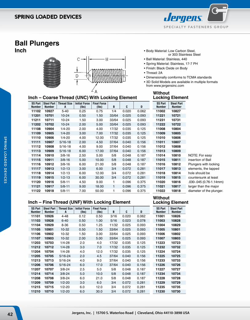
NOTE: For easy insertion of Ball Plungers with locking elements, the tapped hole should be countersunk at least .030-.045 (0.76-1.14mm) larger than the major diameter of the plunger.
Ball PlungersInch
SS Part Steel Part Thread Size Initial Force Final Force SS Part Steel Part Number Number A (lbs) (lbs) B C D Number Number
11102 10927 5-40 0.25 0.75 1/4 0.020 0.062 11002 10827 11201 10701 10-24 0.50 1.50 33/64 0.025 0.093 11221 10721 11211 10711 10-24 1.50 3.00 33/64 0.025 0.093 11231 10731 11202 10702 10-24 2.00 5.00 33/64 0.025 0.093 11222 10722 11108 10904 1/4-20 2.00 4.00 17/32 0.035 0.125 11008 10804 11109 10905 1/4-20 3.00 7.00 17/32 0.035 0.125 11009 10805 11110 10906 1/4-20 4.00 12.00 17/32 0.035 0.125 11010 10806 11111 10907 5/16-18 2.00 4.50 37/64 0.040 0.156 11011 10807 11112 10908 5/16-18 4.00 9.00 37/64 0.040 0.156 11012 10808 11113 10909 5/16-18 6.00 17.00 37/64 0.040 0.156 11013 10809 11114 10910 3/8-16 2.50 5.00 5/8 0.048 0.187 11014 10810 11115 10911 3/8-16 5.00 10.00 5/8 0.048 0.187 11015 10811 11116 10912 3/8-16 6.00 21.00 5/8 0.048 0.187 11016 10812 11117 10913 1/2-13 3.00 6.00 3/4 0.072 0.281 11017 10813 11118 10914 1/2-13 6.00 12.00 3/4 0.072 0.281 11018 10814 11119 10915 1/2-13 6.00 30.00 3/4 0.072 0.281 11019 10815 11120 10916 5/8-11 4.50 9.00 1 0.096 0.375 11020 10816 11121 10917 5/8-11 9.00 18.00 1 0.096 0.375 11021 10817 11122 10918 5/8-11 7.00 50.00 1 0.096 0.375 11022 10818
SS Part Steel Part Thread Size Initial Force Final Force SS Part Steel Part Number Number A (lbs) (lbs) B C D Number Number
11101 10926 4-48 0.12 0.50 3/16 0.020 0.062 11001 10826 11103 10928 6-40 0.50 1.00 5/16 0.023 0.078 11003 10828 11104 10929 8-36 0.50 1.25 11/32 0.025 0.093 11004 10829 11105 10901 10-32 0.50 1.50 33/64 0.025 0.093 11005 10801 11106 10902 10-32 1.50 3.00 33/64 0.025 0.093 11006 10802 11107 10903 10-32 2.00 5.00 33/64 0.025 0.093 11007 10803 11203 10703 1/4-28 2.0 4.0 17/32 0.035 0.125 11223 10723 11212 10712 1/4-28 3.0 7.0 17/32 0.035 0.125 11232 10732 11204 10704 1/4-28 4.0 12.0 17/32 0.035 0.125 11224 10724 11205 10705 5/16-24 2.0 4.5 37/64 0.040 0.156 11225 10725 11213 10713 5/16-24 4.0 9.0 37/64 0.040 0.156 11233 10733 11206 10706 5/16-24 6.0 17.0 37/64 0.040 0.156 11226 10726 11207 10707 3/8-24 2.5 5.0 5/8 0.048 0.187 11227 10727 11214 10714 3/8-24 5.0 10.0 5/8 0.048 0.187 11234 10734 11208 10708 3/8-24 6.0 21.0 5/8 0.048 0.187 11228 10728 11209 10709 1/2-20 3.0 6.0 3/4 0.072 0.281 11229 10729 11215 10715 1/2-20 6.0 12.0 3/4 0.072 0.281 11235 10735 11210 10710 1/2-20 6.0 30.0 3/4 0.072 0.281 11230 10730
Inch – Fine Thread (UNF) With Locking ElementWithout Locking Element
Inch – Coarse Thread (UNC) With Locking ElementWithout Locking Element
•Body Material: Low Carbon Steel, or 303 Stainless Steel
•Ball Material: Stainless, 440•Spring Material: Stainless, 17-7 PH•Finish: Black Oxide on Body•Thread: 2A•Dimensionally comforms to TCMA standards•3D Solid Models are available in multiple formats
from www.jergensinc.com
43Phone: 866-KWIK-LOK (594-5565) | Fax: +1 216-481-6193 | E-mail: [email protected] | www.jergensinc.com
S P E C I A LT Y FA S T E N E R S G R O U P
SPRING LOADED DEVICES
SP
RIN
G L
OA
DE
D D
EV
ICE
S
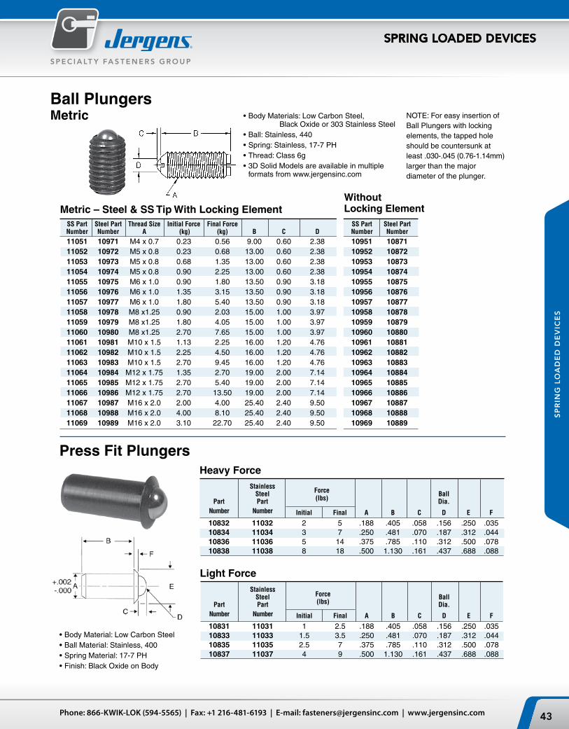
Stainless Steel Force Ball Part Part (lbs) Dia. Number Number Initial Final A B C D E F
10831 11031 1 2.5 .188 .405 .058 .156 .250 .035 10833 11033 1.5 3.5 .250 .481 .070 .187 .312 .044 10835 11035 2.5 7 .375 .785 .110 .312 .500 .078 10837 11037 4 9 .500 1.130 .161 .437 .688 .088
Ball PlungersMetric
Press Fit Plungers
•Body Material: Low Carbon Steel•Ball Material: Stainless, 400•Spring Material: 17-7 PH•Finish: Black Oxide on Body
Stainless Steel Force Ball Part Part (lbs) Dia. Number Number Initial Final A B C D E F
10832 11032 2 5 .188 .405 .058 .156 .250 .035 10834 11034 3 7 .250 .481 .070 .187 .312 .044 10836 11036 5 14 .375 .785 .110 .312 .500 .078 10838 11038 8 18 .500 1.130 .161 .437 .688 .088
Metric – Steel & SS Tip With Locking ElementWithout Locking Element
SS Part Steel Part Thread Size Initial Force Final Force SS Part Steel Part Number Number A (kg) (kg) B C D Number Number
11051 10971 M4 x 0.7 0.23 0.56 9.00 0.60 2.38 10951 10871 11052 10972 M5 x 0.8 0.23 0.68 13.00 0.60 2.38 10952 10872 11053 10973 M5 x 0.8 0.68 1.35 13.00 0.60 2.38 10953 10873 11054 10974 M5 x 0.8 0.90 2.25 13.00 0.60 2.38 10954 10874 11055 10975 M6 x 1.0 0.90 1.80 13.50 0.90 3.18 10955 10875 11056 10976 M6 x 1.0 1.35 3.15 13.50 0.90 3.18 10956 10876 11057 10977 M6 x 1.0 1.80 5.40 13.50 0.90 3.18 10957 10877 11058 10978 M8 x1.25 0.90 2.03 15.00 1.00 3.97 10958 10878 11059 10979 M8 x1.25 1.80 4.05 15.00 1.00 3.97 10959 10879 11060 10980 M8 x1.25 2.70 7.65 15.00 1.00 3.97 10960 10880 11061 10981 M10 x 1.5 1.13 2.25 16.00 1.20 4.76 10961 10881 11062 10982 M10 x 1.5 2.25 4.50 16.00 1.20 4.76 10962 10882 11063 10983 M10 x 1.5 2.70 9.45 16.00 1.20 4.76 10963 10883 11064 10984 M12 x 1.75 1.35 2.70 19.00 2.00 7.14 10964 10884 11065 10985 M12 x 1.75 2.70 5.40 19.00 2.00 7.14 10965 10885 11066 10986 M12 x 1.75 2.70 13.50 19.00 2.00 7.14 10966 10886 11067 10987 M16 x 2.0 2.00 4.00 25.40 2.40 9.50 10967 10887 11068 10988 M16 x 2.0 4.00 8.10 25.40 2.40 9.50 10968 10888 11069 10989 M16 x 2.0 3.10 22.70 25.40 2.40 9.50 10969 10889
•Body Materials: Low Carbon Steel, Black Oxide or 303 Stainless Steel
•Ball: Stainless, 440•Spring: Stainless, 17-7 PH•Thread: Class 6g•3D Solid Models are available in multiple
formats from www.jergensinc.com
NOTE: For easy insertion of Ball Plungers with locking elements, the tapped hole should be countersunk at least .030-.045 (0.76-1.14mm) larger than the major diameter of the plunger.
Heavy Force
Light Force
Jergens, Inc. | 15700 S. Waterloo Road | Cleveland, Ohio 44110-3898 USA44
S P E C I A LT Y F A S T E N E R S G R O U P
SPRING LOADED DEVICES
SP
RIN
G L
OA
DE
D D
EV
ICE
S
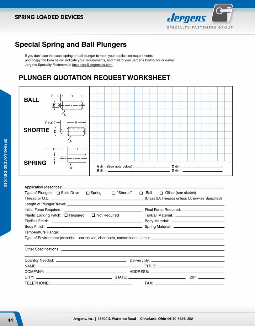
Special Spring and Ball PlungersIf you don’t see the exact spring or ball plunger to meet your application requirements, photocopy the form below, indicate your requirements, and mail to your Jergens Distributor or e-mail Jergens Specialty Fasteners at [email protected].
PLUNGER QUOTATION REQUEST WORKSHEET
Application (describe):
Type of Plunger: Solid Drive Spring “Shortie” Ball Other (see sketch)
Thread or O.D. (Class 2A Threads unless Otherwise Specified)
Length of Plunger Travel:
Initial Force Required: Final Force Required:
Plastic Locking Patch: Required Not Required Tip/Ball Material:
Tip/Ball Finish: Body Material:
Body Finish: Spring Material:
Temperature Range:
Type of Environment (describe—corrosives, chemicals, contaminants, etc.):
Other Specifications:
Quantity Needed: Delivery By:
NAME: TITLE:
COMPANY: ADDRESS:
CITY: STATE: ZIP:
TELEPHONE: FAX:
A dim. (See note below) C dim.B dim. D dim.
SHORTIE
BALL
SPRING
45Phone: 866-KWIK-LOK (594-5565) | Fax: +1 216-481-6193 | E-mail: [email protected] | www.jergensinc.com
S P E C I A LT Y FA S T E N E R S G R O U P
SPRING LOADED DEVICES
SP
RIN
G L
OA
DE
D D
EV
ICE
S
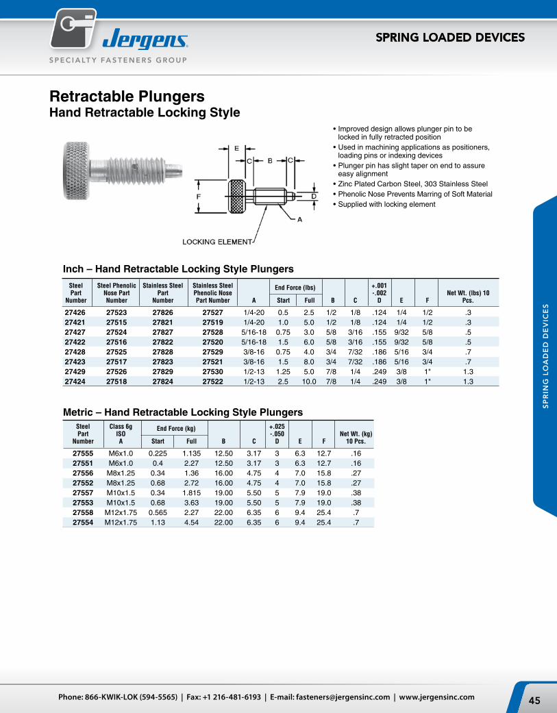
Retractable PlungersHand Retractable Locking Style
•Improved design allows plunger pin to be locked in fully retracted position
•Used in machining applications as positioners, loading pins or indexing devices
•Plunger pin has slight taper on end to assure easy alignment
•Zinc Plated Carbon Steel, 303 Stainless Steel•Phenolic Nose Prevents Marring of Soft Material•Supplied with locking element
Inch – Hand Retractable Locking Style Plungers
Metric – Hand Retractable Locking Style Plungers
Steel Steel Phenolic Stainless Steel Stainless Steel +.001 Part Nose Part Part Phenolic Nose
End Force (lbs) -.002 Net Wt. (lbs) 10
Number Number Number Part Number A Start Full B C D E F Pcs.
27426 27523 27826 27527 1/4-20 0.5 2.5 1/2 1/8 .124 1/4 1/2 .327421 27515 27821 27519 1/4-20 1.0 5.0 1/2 1/8 .124 1/4 1/2 .327427 27524 27827 27528 5/16-18 0.75 3.0 5/8 3/16 .155 9/32 5/8 .527422 27516 27822 27520 5/16-18 1.5 6.0 5/8 3/16 .155 9/32 5/8 .527428 27525 27828 27529 3/8-16 0.75 4.0 3/4 7/32 .186 5/16 3/4 .727423 27517 27823 27521 3/8-16 1.5 8.0 3/4 7/32 .186 5/16 3/4 .727429 27526 27829 27530 1/2-13 1.25 5.0 7/8 1/4 .249 3/8 1" 1.327424 27518 27824 27522 1/2-13 2.5 10.0 7/8 1/4 .249 3/8 1" 1.3
Steel Class 6g +.025 Part ISO
End Force (kg) -.050 Net Wt. (kg)
Number A Start Full B C D E F 10 Pcs.
27555 M6x1.0 0.225 1.135 12.50 3.17 3 6.3 12.7 .16 27551 M6x1.0 0.4 2.27 12.50 3.17 3 6.3 12.7 .16 27556 M8x1.25 0.34 1.36 16.00 4.75 4 7.0 15.8 .27 27552 M8x1.25 0.68 2.72 16.00 4.75 4 7.0 15.8 .27 27557 M10x1.5 0.34 1.815 19.00 5.50 5 7.9 19.0 .38 27553 M10x1.5 0.68 3.63 19.00 5.50 5 7.9 19.0 .38 27558 M12x1.75 0.565 2.27 22.00 6.35 6 9.4 25.4 .7 27554 M12x1.75 1.13 4.54 22.00 6.35 6 9.4 25.4 .7
Jergens, Inc. | 15700 S. Waterloo Road | Cleveland, Ohio 44110-3898 USA46
S P E C I A LT Y F A S T E N E R S G R O U P
SPRING LOADED DEVICES
SP
RIN
G L
OA
DE
D D
EV
ICE
S
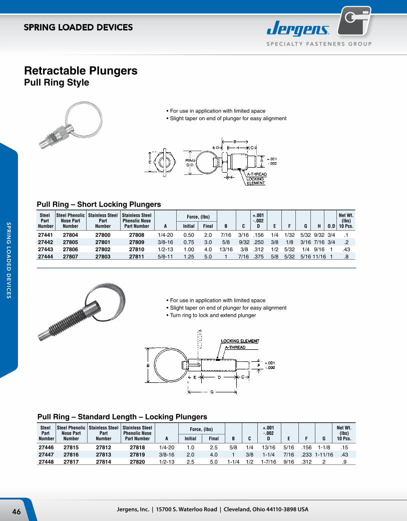
Retractable PlungersPull Ring Style
•For use in application with limited space•Slight taper on end of plunger for easy alignment
Pull Ring – Standard Length – Locking Plungers
Steel Steel Phenolic Stainless Steel Stainless Steel +.001 Net Wt. Part Nose Part Part Phenolic Nose
Force, (lbs) -.002 (lbs)
Number Number Number Part Number A Initial Final B C D E F G H O.D 10 Pcs.
27441 27804 27800 27808 1/4-20 0.50 2.0 7/16 3/16 .156 1/4 1/32 5/32 9/32 3/4 .1 27442 27805 27801 27809 3/8-16 0.75 3.0 5/8 9/32 .250 3/8 1/8 3/16 7/16 3/4 .2 27443 27806 27802 27810 1/2-13 1.00 4.0 13/16 3/8 .312 1/2 5/32 1/4 9/16 1 .43 27444 27807 27803 27811 5/8-11 1.25 5.0 1 7/16 .375 5/8 5/32 5/16 11/16 1 .8
Pull Ring – Short Locking Plungers
•For use in application with limited space•Slight taper on end of plunger for easy alignment•Turn ring to lock and extend plunger
Steel Steel Phenolic Stainless Steel Stainless Steel +.001 Net Wt. Part Nose Part Part Phenolic Nose
Force, (lbs) -.002 (lbs)
Number Number Number Part Number A Initial Final B C D E F G 10 Pcs.
27446 27815 27812 27818 1/4-20 1.0 2.5 5/8 1/4 13/16 5/16 .156 1-1/8 .1527447 27816 27813 27819 3/8-16 2.0 4.0 1 3/8 1-1/4 7/16 .233 1-11/16 .4327448 27817 27814 27820 1/2-13 2.5 5.0 1-1/4 1/2 1-7/16 9/16 .312 2 .9
47Phone: 866-KWIK-LOK (594-5565) | Fax: +1 216-481-6193 | E-mail: [email protected] | www.jergensinc.com
S P E C I A LT Y FA S T E N E R S G R O U P
SPRING LOADED DEVICES
SP
RIN
G L
OA
DE
D D
EV
ICE
S
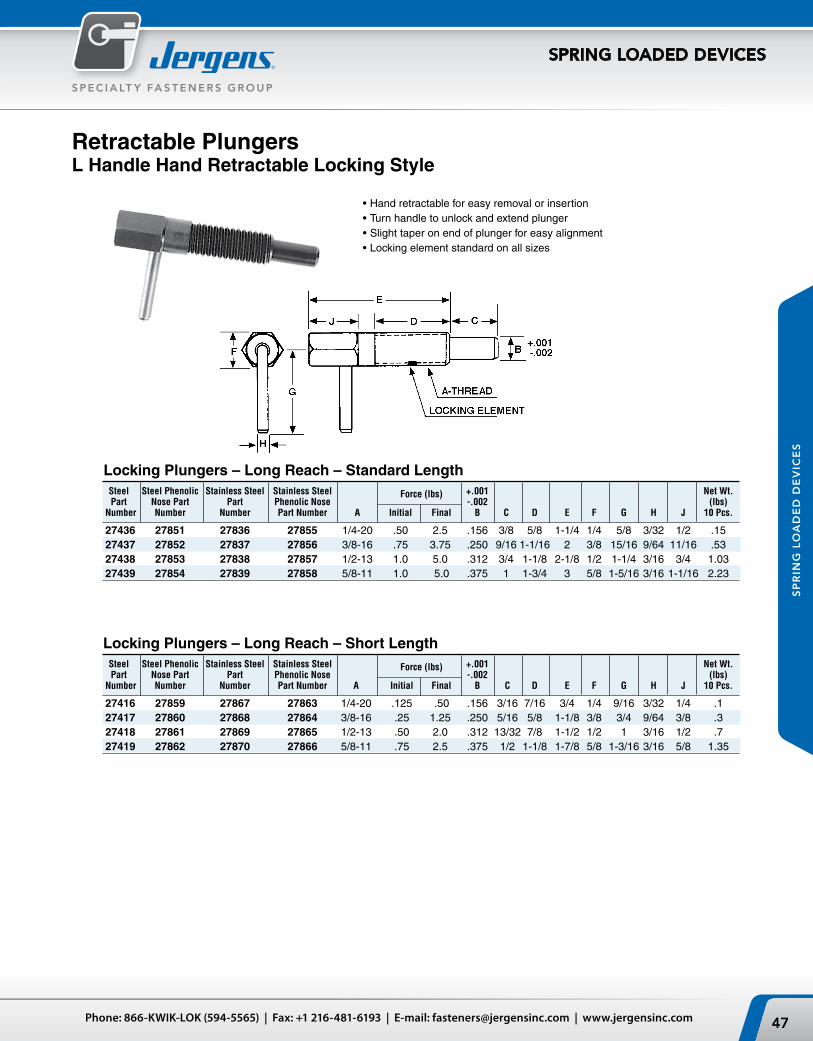
Retractable PlungersL Handle Hand Retractable Locking Style
•Hand retractable for easy removal or insertion•Turn handle to unlock and extend plunger•Slight taper on end of plunger for easy alignment•Locking element standard on all sizes
Locking Plungers – Long Reach – Standard Length
Locking Plungers – Long Reach – Short Length
Steel Steel Phenolic Stainless Steel Stainless Steel +.001 Net Wt. Part Nose Part Part Phenolic Nose
Force (lbs) -.002 (lbs)
Number Number Number Part Number A Initial Final B C D E F G H J 10 Pcs.
27436 27851 27836 27855 1/4-20 .50 2.5 .156 3/8 5/8 1-1/4 1/4 5/8 3/32 1/2 .15 27437 27852 27837 27856 3/8-16 .75 3.75 .250 9/16 1-1/16 2 3/8 15/16 9/64 11/16 .53 27438 27853 27838 27857 1/2-13 1.0 5.0 .312 3/4 1-1/8 2-1/8 1/2 1-1/4 3/16 3/4 1.03 27439 27854 27839 27858 5/8-11 1.0 5.0 .375 1 1-3/4 3 5/8 1-5/16 3/16 1-1/16 2.23
Steel Steel Phenolic Stainless Steel Stainless Steel +.001 Net Wt. Part Nose Part Part Phenolic Nose
Force (lbs) -.002 (lbs)
Number Number Number Part Number A Initial Final B C D E F G H J 10 Pcs.
27416 27859 27867 27863 1/4-20 .125 .50 .156 3/16 7/16 3/4 1/4 9/16 3/32 1/4 .1 27417 27860 27868 27864 3/8-16 .25 1.25 .250 5/16 5/8 1-1/8 3/8 3/4 9/64 3/8 .3 27418 27861 27869 27865 1/2-13 .50 2.0 .312 13/32 7/8 1-1/2 1/2 1 3/16 1/2 .7 27419 27862 27870 27866 5/8-11 .75 2.5 .375 1/2 1-1/8 1-7/8 5/8 1-3/16 3/16 5/8 1.35
Jergens, Inc. | 15700 S. Waterloo Road | Cleveland, Ohio 44110-3898 USA48
S P E C I A LT Y F A S T E N E R S G R O U P
SPRING LOADED DEVICES
SP
RIN
G L
OA
DE
D D
EV
ICE
S
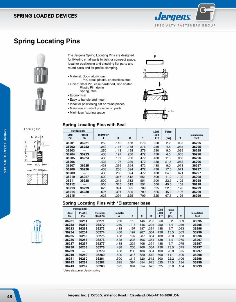
Spring Locating Pins
The Jergens Spring Locating Pins are designed for fixturing small parts in tight or compact space. Ideal for positioning and chucking flat parts and round parts and for profile clamping.
•Material: Body, aluminum Pin, steel, plastic, or stainless steel
•Finish: Steel Pin, case hardened, zinc coated Plastic Pin, delrin Spring, steel
•Economical•Easy to handle and mount•Ideal for positioning flat or round pieces•Maintains constant pressure on parts•Minimizes fixturing space
Part Number +.001 Force Steel Plastic Diameter -.000 P Installation Pin Pin A B C D E (lbs) X Tool
36201 36221 .250 .118 .158 .276 .250 2.2 .035 36295 36202 36222 .250 .118 .158 .276 .250 4.5 .035 36295 36203 — .250 .118 .158 .276 .250 9.0 .035 36295 36204 36223 .438 .197 .236 .472 .438 4.5 .063 36296 36205 36224 .438 .197 .236 .472 .438 11.2 .063 36296 36206 — .438 .197 .236 .472 .438 21.5 .063 36296 36207 36225 .438 .236 .394 .472 .438 9.0 .071 36297 36208 36226 .438 .236 .394 .472 .438 17.0 .071 36297 36209 — .438 .236 .394 .472 .438 34.0 .071 36297 36210 36227 .500 .315 .512 .551 .500 11.2 .102 36298 36211 36228 .500 .315 .512 .551 .500 22.5 .102 36298 36212 — .500 .315 .512 .551 .500 45.0 .102 36298 36213 36229 .625 .394 .625 .709 .625 22.5 .126 36299 36214 36230 .625 .394 .625 .709 .625 45.0 .126 36299 36215 — .625 .394 .625 .709 .625 67.5 .126 36299
Spring Locating Pins with *Elastomer base
Part Number +.001 Force Steel Plastic Stainless Diameter -.000 P Installation Pin Pin Steel Pin A B C D E (lbs) X Tool
36231 36251 36271 .250 .118 .146 .295 .250 2.2 .039 36295 36232 36252 36272 .250 .118 .146 .295 .250 4.4 .039 36295 36233 36253 36273 .438 .197 .287 .354 .438 6.7 .063 36296 36234 36254 36274 .438 .197 .287 .354 .438 13.5 .063 36296 36235 36255 36275 .438 .197 .287 .354 .438 20.0 .063 36296 36236 36256 36276 .438 .236 .406 .354 .438 4.4 .075 36297 36237 36257 36277 .438 .236 .406 .354 .438 6.7 .075 36297 36238 36258 36278 .438 .236 .406 .354 .438 13.5 .075 36297 36239 — 36279 .438 .236 .406 .354 .438 20.0 .075 36297 36240 36259 36280 .500 .315 .520 .512 .500 11.1 .106 36298 36241 36260 36281 .500 .315 .520 .512 .500 22.2 .106 36298 36242 36261 36282 .625 .394 .654 .625 .625 17.5 .134 36299 36243 36262 36283 .625 .394 .654 .625 .625 35.0 .134 36299*Uses elastomer plastic spring
H8
H8
Spring Locating Pins with Seal
49Phone: 866-KWIK-LOK (594-5565) | Fax: +1 216-481-6193 | E-mail: [email protected] | www.jergensinc.com
S P E C I A LT Y FA S T E N E R S G R O U P
SPRING LOADED DEVICES
SP
RIN
G L
OA
DE
D D
EV
ICE
S
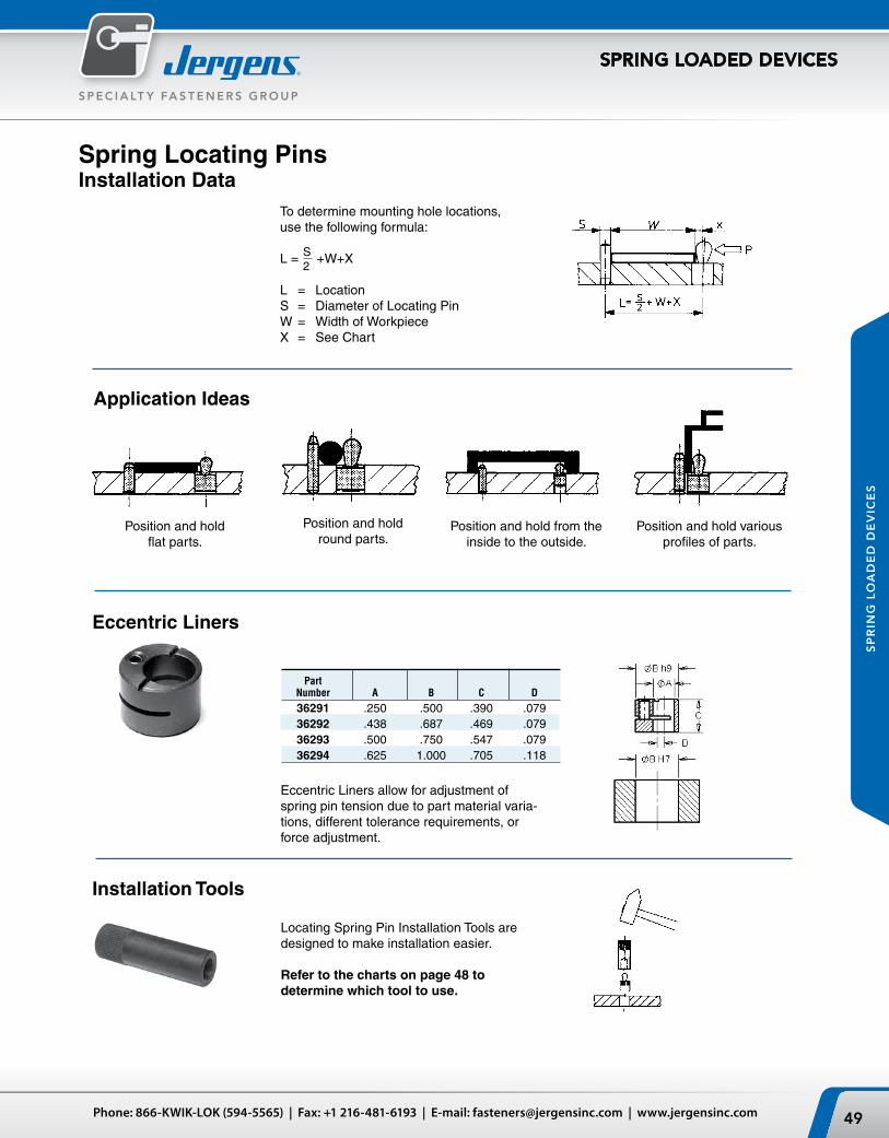
Spring Locating PinsInstallation Data
To determine mounting hole locations, use the following formula:
L = +W+X
L = LocationS = Diameter of Locating PinW = Width of WorkpieceX = See Chart
Installation Tools
Part Number A B C D
36291 .250 .500 .390 .079 36292 .438 .687 .469 .079 36293 .500 .750 .547 .079 36294 .625 1.000 .705 .118
Eccentric Liners allow for adjustment of spring pin tension due to part material varia-tions, different tolerance requirements, or force adjustment.
Eccentric Liners
Locating Spring Pin Installation Tools are designed to make installation easier. Refer to the charts on page 48 to determine which tool to use.
S2
Position and hold flat parts.
Position and hold round parts.
Position and hold from the inside to the outside.
Position and hold various profiles of parts.
Application Ideas
Jergens, Inc. | 15700 S. Waterloo Road | Cleveland, Ohio 44110-3898 USA50
S P E C I A LT Y F A S T E N E R S G R O U P
SPRING LOADED DEVICES
SP
RIN
G L
OA
DE
D D
EV
ICE
S
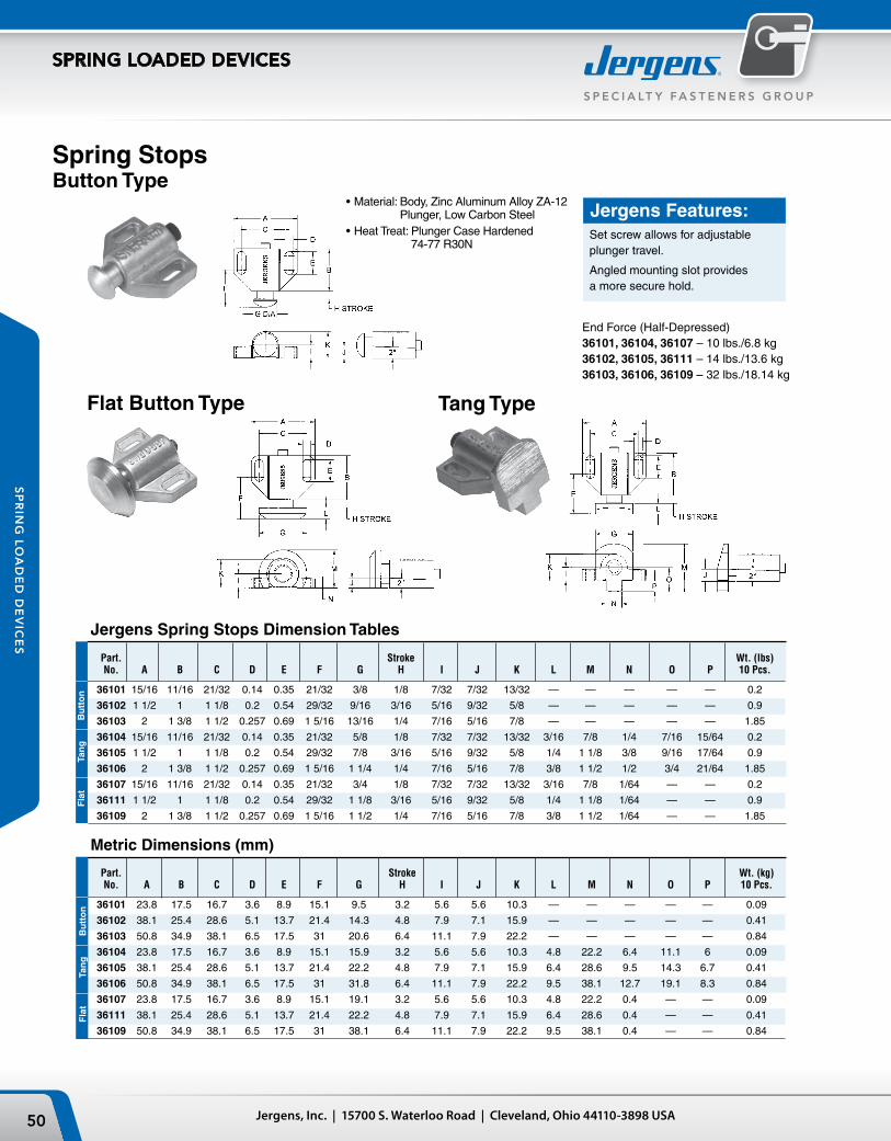
Spring StopsButton Type
Tang TypeFlat Button Type
Jergens Features:Set screw allows for adjustable plunger travel.
Angled mounting slot provides a more secure hold.
End Force (Half-Depressed)36101, 36104, 36107 – 10 lbs./6.8 kg36102, 36105, 36111 – 14 lbs./13.6 kg36103, 36106, 36109 – 32 lbs./18.14 kg
•Material: Body, Zinc Aluminum Alloy ZA-12 Plunger, Low Carbon Steel
•Heat Treat: Plunger Case Hardened 74-77 R30N
Bu
tto
nTa
ng
Fla
tB
utt
on
Tan
gF
lat
Jergens Spring Stops Dimension Tables
Part. Stroke Wt. (lbs) No. A B C D E F G H I J K L M N O P 10 Pcs.
36101 15/16 11/16 21/32 0.14 0.35 21/32 3/8 1/8 7/32 7/32 13/32 — — — — — 0.2
36102 1 1/2 1 1 1/8 0.2 0.54 29/32 9/16 3/16 5/16 9/32 5/8 — — — — — 0.9
36103 2 1 3/8 1 1/2 0.257 0.69 1 5/16 13/16 1/4 7/16 5/16 7/8 — — — — — 1.85
36104 15/16 11/16 21/32 0.14 0.35 21/32 5/8 1/8 7/32 7/32 13/32 3/16 7/8 1/4 7/16 15/64 0.2
36105 1 1/2 1 1 1/8 0.2 0.54 29/32 7/8 3/16 5/16 9/32 5/8 1/4 1 1/8 3/8 9/16 17/64 0.9
36106 2 1 3/8 1 1/2 0.257 0.69 1 5/16 1 1/4 1/4 7/16 5/16 7/8 3/8 1 1/2 1/2 3/4 21/64 1.85
36107 15/16 11/16 21/32 0.14 0.35 21/32 3/4 1/8 7/32 7/32 13/32 3/16 7/8 1/64 — — 0.2
36111 1 1/2 1 1 1/8 0.2 0.54 29/32 1 1/8 3/16 5/16 9/32 5/8 1/4 1 1/8 1/64 — — 0.9
36109 2 1 3/8 1 1/2 0.257 0.69 1 5/16 1 1/2 1/4 7/16 5/16 7/8 3/8 1 1/2 1/64 — — 1.85
Metric Dimensions (mm)
Part. Stroke Wt. (kg) No. A B C D E F G H I J K L M N O P 10 Pcs.
36101 23.8 17.5 16.7 3.6 8.9 15.1 9.5 3.2 5.6 5.6 10.3 — — — — — 0.09
36102 38.1 25.4 28.6 5.1 13.7 21.4 14.3 4.8 7.9 7.1 15.9 — — — — — 0.41
36103 50.8 34.9 38.1 6.5 17.5 31 20.6 6.4 11.1 7.9 22.2 — — — — — 0.84
36104 23.8 17.5 16.7 3.6 8.9 15.1 15.9 3.2 5.6 5.6 10.3 4.8 22.2 6.4 11.1 6 0.09
36105 38.1 25.4 28.6 5.1 13.7 21.4 22.2 4.8 7.9 7.1 15.9 6.4 28.6 9.5 14.3 6.7 0.41
36106 50.8 34.9 38.1 6.5 17.5 31 31.8 6.4 11.1 7.9 22.2 9.5 38.1 12.7 19.1 8.3 0.84
36107 23.8 17.5 16.7 3.6 8.9 15.1 19.1 3.2 5.6 5.6 10.3 4.8 22.2 0.4 — — 0.09
36111 38.1 25.4 28.6 5.1 13.7 21.4 22.2 4.8 7.9 7.1 15.9 6.4 28.6 0.4 — — 0.41
36109 50.8 34.9 38.1 6.5 17.5 31 38.1 6.4 11.1 7.9 22.2 9.5 38.1 0.4 — — 0.84


![INDEX [] Spring Loaded Devices ... Spring Stops ... 63909 63969 Zinc 64009 64069 Plain 1.80 3.35 M10 x 1.5 19 (.748) 2 (.079) 6 ...](https://static.fdocuments.net/doc/165x107/5b0d00f07f8b9a02508d0542/index-spring-loaded-devices-spring-stops-63909-63969-zinc-64009-64069.jpg)


