Spring 2001 Gems & Gemology - Ammolite
95
Transcript of Spring 2001 Gems & Gemology - Ammolite
pg. 74
EDITORIAL
REGULAR FEATURES
pg. 43
4
FEATURE ARTICLES
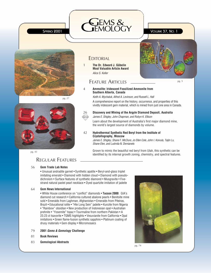
A comprehensive report on the history, occurrence, and properties of thisvividly iridescent gem material, which is mined from just one area in Canada.
Keith A. Mychaluk, Alfred A. Levinson, and Russell L. Hall
Ammolite: Iridescent Fossilized Ammonite from Southern Alberta, Canada
1
Alice S. Keller
The Dr. Edward J. GübelinMost Valuable Article Award
42
Grown to mimic the beautiful red beryl from Utah, this synthetic can beidentified by its internal growth zoning, chemistry, and spectral features.
James E. Shigley, Shane F. McClure, Jo Ellen Cole, John I. Koivula, Taijin Lu, Shane Elen, and Ludmila N. Demianets
Hydrothermal Synthetic Red Beryl from the Institute of Crystallography, Moscow
26
Learn about the development of Australia’s first major diamond mine,the world’s largest source of diamonds by volume.
James E. Shigley, John Chapman, and Robyn K. EllisonDiscovery and Mining of the Argyle Diamond Deposit, Australia
56• Unusual andradite garnet • Synthetic apatite • Beryl-and-glass tripletimitating emerald • Diamond with hidden cloud • Diamond with pseudo-dichroism • Surface features of synthetic diamond • Musgravite • Five-strand natural pastel pearl necklace • Dyed quartzite imitation of jadeite
Gem Trade Lab Notes
79 2001 Gems & Gemology Challenge
83 Gemological Abstracts
81 Book Reviews
64• White House conference on “conflict” diamonds • Tucson 2000: GIA’sdiamond cut research • California cultured abalone pearls • Benitoite minesold • Emeralds from Laghman, Afghanistan • Emeralds from Piteiras,Brazil • Educational iolite • “Hte Long Sein” jadeite • Kunzite from Nigeria• “Rainbow” obsidian • New production of Indonesian opal • Australianprehnite • “Yosemite” topaz • Tourmaline from northern Pakistan • A23.23 ct tsavorite • TGMS highlights • Vesuvianite from California • Opalimitations • Green flame-fusion synthetic sapphire • Platinum coating ofdrusy materials • Gem display • Micromosaics
Gem News International
pg. 27
pg. 5
VOLUME 37, NO. 1SPRING 2001
MOST VALUABLE ARTICLE AWARD GEMS & GEMOLOGY SPRING 2001 1
T he ballots are in, and we are pleased to announce the winnersof this year’s Dr. Edward J. Gübelin Most Valuable ArticleAward. We extend our sincerest thanks to all the subscribers
who participated in the voting.The first-place article, “Gemstone Enhancement and Detection
in the 1990s” (Winter 2000), examined the prominent gem treat-ments of the last decade and discussed methods for their detection.Finishing in a close second place was “GE POL Diamonds: Beforeand After” (Fall 2000), which provided important clues to the identi-fication of type IIa diamonds that had undergone high pressure/hightemperature (HPHT) processing by General Electric. Third place wasawarded to “Gem Localities of the 1990s” (Winter 2000), a review ofthe decade’s new gemstone sources and its most important produc-ing localities.
The authors of these three articles will share cash prizes of$1,000, $500, and $300, respectively. Following are photographs andbrief biographies of the winning authors.
Congratulations also to Ron Suddendorf of Darnestown, Maryland,whose ballot was drawn from the many entries to win a leather portfolioand a five-year subscription to Gems & Gemology.
See some changes in this issue? With the new decade-century-mil-lennium, we’ve been updating the design of Gems & Gemology andhave expanded the Gem News section to Gem News International.Please be assured that there has been no change in the quality of theinformation provided throughout. Just a more contemporary look for apublication—now 67 years young—that will continue to keep you onthe leading edge of gemology as we enter this new era.
Alice S. Keller, [email protected]
The Dr. Edward J. Gübelin Most Valuable Article Award
Shane McClure Christopher Smith
First PlaceGemstone Enhancement and Detection in the 1990sShane F. McClure and Christopher P. Smith
Shane McClure, G.G., is director of West Coast Identification Services atthe GIA Gem Trade Laboratory in Carlsbad. With over 20 years of laborato-ry experience, Mr. McClure is well known for his articles and lectures ongem identification. He is also an editor of the Gem Trade Lab Notes sec-tion. Chicago native Christopher Smith, G.G., is director of the GübelinGem Lab in Lucerne, Switzerland. A prolific author, Mr. Smith is a mem-ber of the Gems & Gemology Editorial Review Board.
2 MOST VALUABLE ARTICLE AWARD GEMS & GEMOLOGY SPRING 2001
Second PlaceGE POL Diamonds: Before and AfterChristopher P. Smith, George Bosshart, Johann Ponahlo,Vera M. F. Hammer, Helmut Klapper, and Karl Schmetzer
Christopher Smith is profiled in the first-place entry. George Bosshart,who holds a degree in mineralogy from the Swiss Federal Institute ofTechnology in Zürich, is chief gemologist at the Gübelin Gem Lab. Hecurrently is involved in research on HPHT-enhanced diamonds. JohannPonahlo has been an independent research associate at the Museum ofNatural History in Vienna since 1990. A physicochemist with a degreefrom the Technical University of Vienna, Dr. Ponahlo specializes in thestudy of cathodoluminescence in gems, particularly diamonds and jade.Vera M. F. Hammer has been the curatorial assistant for the mineral andgem collection of the Federal Gem Institute at the Museum of NaturalHistory in Vienna since 1992. Dr. Hammer studied mineralogy and crys-tallography at the University of Vienna. Her research specialties are X-ray diffraction analysis, the gemology of colored diamonds, and UV-Vis-IR-spectroscopy of colored gemstones. Helmut Klapper received his doc-torate in crystallography from the University of Cologne. Since 1990, hehas been professor of mineralogy and crystallography and head of thecrystal growth laboratory of the University of Bonn. Dr. Klapper’s mainresearch fields are crystal physics, crystal growth, and the characteriza-tion of crystal defects by X-ray diffraction topography. Karl Schmetzer,who obtained his doctorate in mineralogy and crystallography fromHeidelberg University, is a research scientist residing in Petershausen,near Munich, Germany. Dr. Schmetzer has written numerous articles onnatural and synthetic gems, and is also a member of the G&G EditorialReview Board.
Third PlaceGem Localities of the 1990sJames E. Shigley, Dona M. Dirlam, Brendan M. Laurs,Edward W. Boehm, George Bosshart, and William F. Larson
James Shigley is director of GIA Research in Carlsbad. Dr. Shigley, whoreceived his Ph.D. in geology from Stanford University, has published anumber of articles on natural, treated, and synthetic gems. He is also amember of the G&G Editorial Review Board. Dona Dirlam, G.G., is direc-tor of the Richard T. Liddicoat Library and Information Center at GIA inCarlsbad. She has a B.Sc. from the University of Minnesota and an M.Sc.in geology and geophysics from the University of Wisconsin, Madison.Brendan Laurs, G.G., is senior editor of Gems & Gemology. He obtained aB.Sc. in geology from the University of California at Santa Barbara and anM.Sc. in geology from Oregon State University. Prior to joining GIA, Mr.Laurs gained experience as an exploration geologist specializing in coloredgems. Edward Boehm, G.G., is a gem dealer and gemological consultant.President of JOEB Enterprises in Solana Beach, California, Mr. Boehm hasa degree in geology and German from the University of North Carolina inChapel Hill. George Bosshart is profiled in the second-place entry. WilliamLarson is president of Pala International (Fallbrook, California), a companythat has been involved with gem-mining projects worldwide. Mr. Larsonholds a degree in geological engineering from the Colorado School ofMines. He has traveled extensively to gem deposits, including 135 tripsinto the Far East and more than 40 visits to Africa.
George Bosshart Johann Ponahlo
Vera Hammer Helmut Klapper
Karl Schmetzer
James Shigley Dona Dirlam
Brendan Laurs Edward Boehm
William Larson
4 AMMOLITE GEMS & GEMOLOGY SPRING 2001
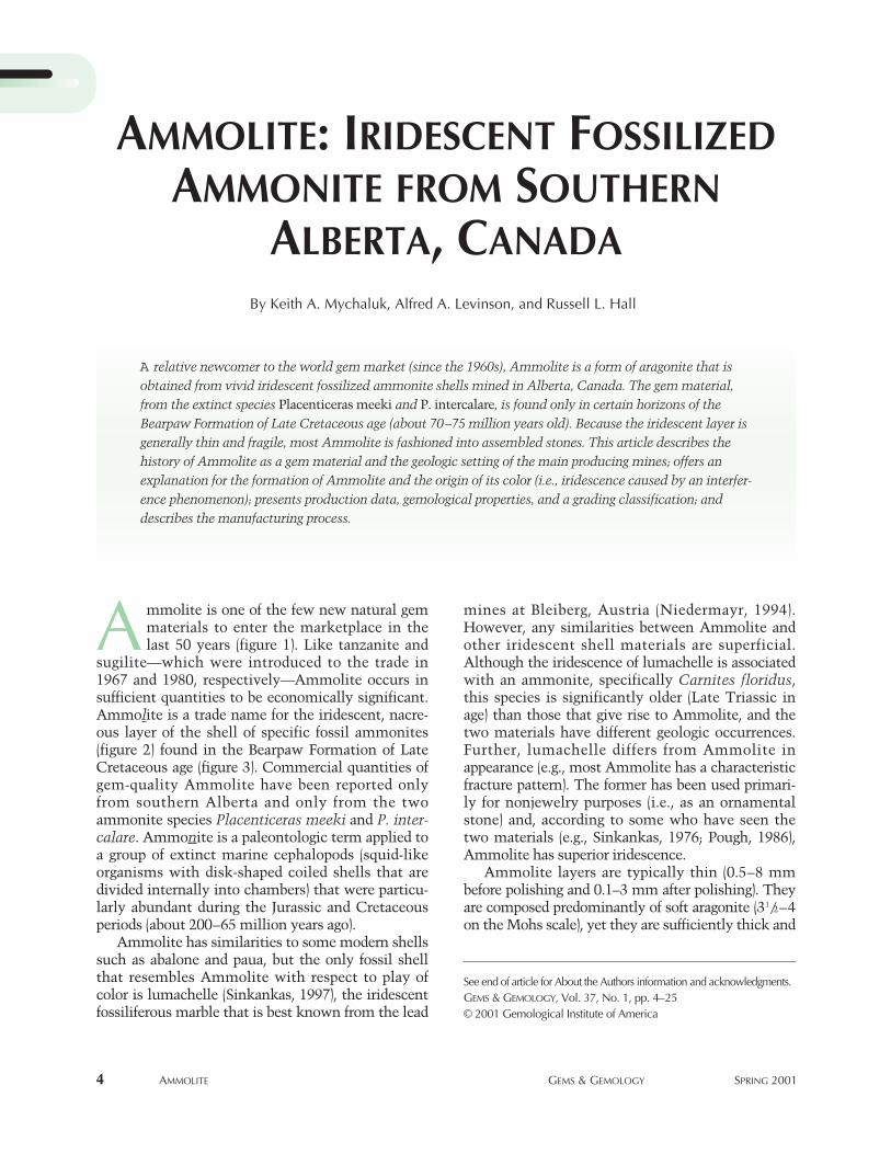
mines at Bleiberg, Austria (Niedermayr, 1994).However, any similarities between Ammolite andother iridescent shell materials are superficial.Although the iridescence of lumachelle is associatedwith an ammonite, specifically Carnites floridus,this species is significantly older (Late Triassic inage) than those that give rise to Ammolite, and thetwo materials have different geologic occurrences.Further, lumachelle differs from Ammolite inappearance (e.g., most Ammolite has a characteristicfracture pattern). The former has been used primari-ly for nonjewelry purposes (i.e., as an ornamentalstone) and, according to some who have seen thetwo materials (e.g., Sinkankas, 1976; Pough, 1986),Ammolite has superior iridescence.
Ammolite layers are typically thin (0.5–8 mmbefore polishing and 0.1–3 mm after polishing). Theyare composed predominantly of soft aragonite (31/2–4on the Mohs scale), yet they are sufficiently thick and
By Keith A. Mychaluk, Alfred A. Levinson, and Russell L. Hall
AMMOLITE: IRIDESCENT FOSSILIZEDAMMONITE FROM SOUTHERN
ALBERTA, CANADA
See end of article for About the Authors information and acknowledgments.GEMS & GEMOLOGY, Vol. 37, No. 1, pp. 4–25© 2001 Gemological Institute of America
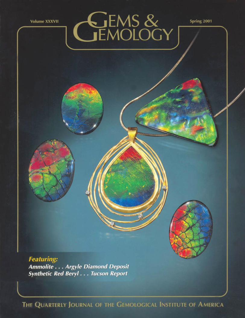
A relative newcomer to the world gem market (since the 1960s), Ammolite is a form of aragonite that isobtained from vivid iridescent fossilized ammonite shells mined in Alberta, Canada. The gem material,from the extinct species Placenticeras meeki and P. intercalare, is found only in certain horizons of theBearpaw Formation of Late Cretaceous age (about 70–75 million years old). Because the iridescent layer isgenerally thin and fragile, most Ammolite is fashioned into assembled stones. This article describes thehistory of Ammolite as a gem material and the geologic setting of the main producing mines; offers anexplanation for the formation of Ammolite and the origin of its color (i.e., iridescence caused by an interfer-ence phenomenon); presents production data, gemological properties, and a grading classification; anddescribes the manufacturing process.
mmolite is one of the few new natural gemmaterials to enter the marketplace in thelast 50 years (figure 1). Like tanzanite and
sugilite—which were introduced to the trade in1967 and 1980, respectively—Ammolite occurs insufficient quantities to be economically significant.Ammolite is a trade name for the iridescent, nacre-ous layer of the shell of specific fossil ammonites(figure 2) found in the Bearpaw Formation of LateCretaceous age (figure 3). Commercial quantities ofgem-quality Ammolite have been reported onlyfrom southern Alberta and only from the twoammonite species Placenticeras meeki and P. inter-calare. Ammonite is a paleontologic term applied toa group of extinct marine cephalopods (squid-likeorganisms with disk-shaped coiled shells that aredivided internally into chambers) that were particu-larly abundant during the Jurassic and Cretaceousperiods (about 200–65 million years ago).
Ammolite has similarities to some modern shellssuch as abalone and paua, but the only fossil shellthat resembles Ammolite with respect to play ofcolor is lumachelle (Sinkankas, 1997), the iridescentfossiliferous marble that is best known from the lead
A
AMMOLITE GEMS & GEMOLOGY SPRING 2001 5
durable (including the ability to take a polish) to bemanufactured into jewelry. In fact, freeform pieces ofsolid Ammolite over 100 ct have been reported(Wight, 1995). Iridescence produces the vivid colorsin this material. The fact that Ammolite can be man-ufactured into jewelry distinguishes it from other iri-descent materials obtained from various fossils(including other ammonites) that are frequently film-like, have dull colors, or are otherwise unsuited forgem purposes. Nevertheless, because Ammolite usu-ally occurs as thin, soft plates, it is found in jewelryprimarily as assembled stones, such as triplets—athin layer of Ammolite attached to a shale backingand covered with a synthetic spinel or quartz cap.Since 1980, both solid Ammolite and assembledAmmolite gemstones have become increasinglyavailable. It is estimated that a total of about 600,000pieces of Ammolite jewelry have been producedsince significant commercial production began 20years ago (P. Paré, pers. comm., 2001).
The purpose of this article is to update gemolo-gists and jewelers on this unique gem material. Forthis study, we focused almost exclusively on mate-rial from the mining and manufacturing opera-tions of Korite International Ltd. (henceforthKorite), Calgary, Alberta, because: (1) about 90% ofthe commercially available material historicallyhas, and still does, come from Korite’s mines; (2)almost all published information on Ammolite isbased on specimens obtained from this company;(3) several other smaller Ammolite miners andmanufacturers were offered the opportunity to par-ticipate in this study, but only one (S. Carbone)
agreed to do so; and (4) Korite allowed us unre-stricted visitation to their mining and manufactur-ing operations, and supplied us with productiondata as well as specimens for research. In addition
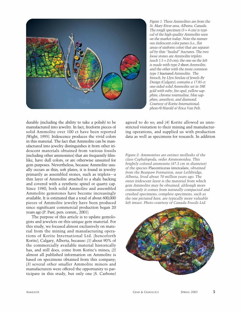
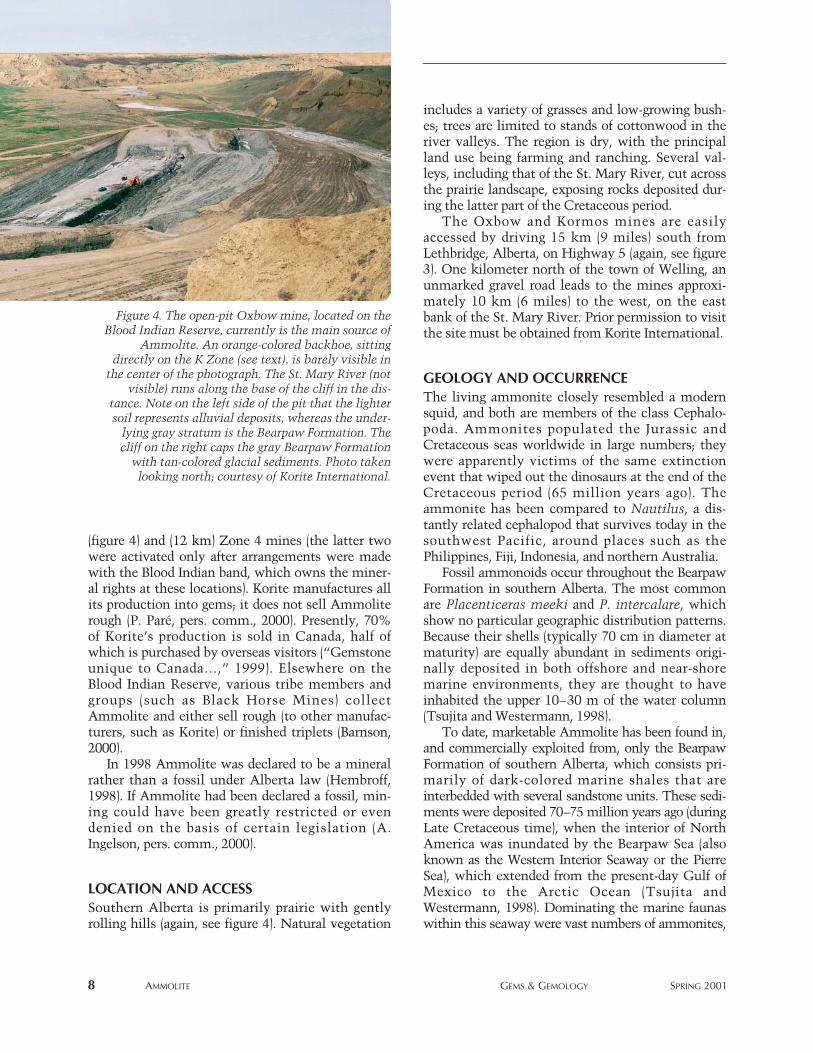
Figure 2. Ammonites are extinct mollusks of theclass Cephalopoda, order Ammonoidea. Thisbrightly colored ammonite (47.3 cm in diameter)of the species Placenticeras intercalare, obtainedfrom the Bearpaw Formation, near Lethbridge,Alberta, lived about 70 million years ago. Theouter iridescent layer is the material from whichgem Ammolite may be obtained, although morecommonly it comes from naturally compacted andcrushed specimens; complete specimens, such asthe one pictured here, are typically more valuableleft intact. Photo courtesy of Canada Fossils Ltd.
Figure 1. These Ammolites are from theSt. Mary River area, Alberta, Canada.The rough specimen (3 × 4 cm) is typi-cal of the high-quality Ammolite seenon the market today. Note the numer-ous iridescent color panes (i.e., flatareas of uniform color) that are separat-ed by thin “healed” fractures. The twoloose stones are Ammolite triplets(each 1.5 × 2.0 cm); the one on the leftis made with type 2 sheet Ammolite,and the other with the more commontype 1 fractured Ammolite. Thebrooch, by Llyn Strelau of Jewels ByDesign (Calgary), contains a 17.85 ctone-sided solid Ammolite set in 18Kgold with ruby, fire opal, yellow sap-phire, chrome tourmaline, blue sap-phire, amethyst, and diamond.Courtesy of Korite International; photo © Harold & Erica Van Pelt.
6 AMMOLITE GEMS & GEMOLOGY SPRING 2001
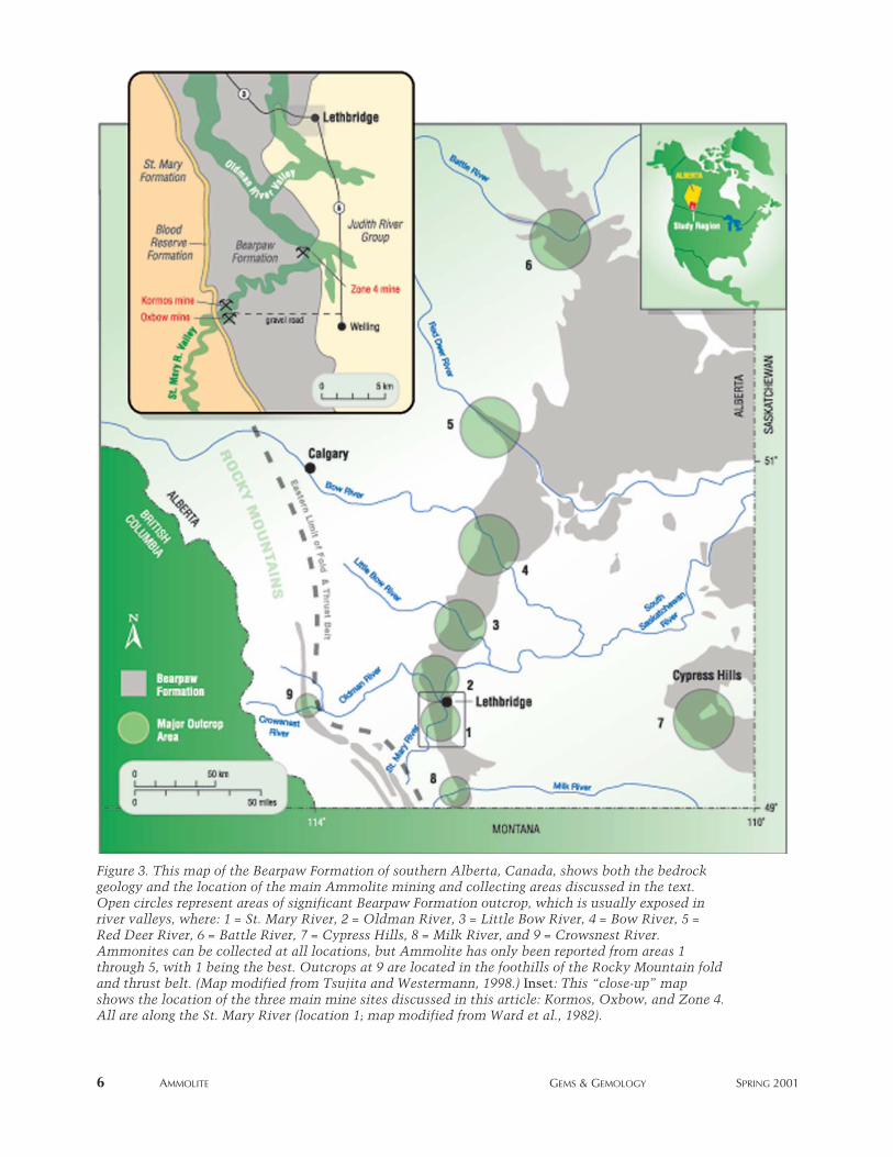
Figure 3. This map of the Bearpaw Formation of southern Alberta, Canada, shows both the bedrockgeology and the location of the main Ammolite mining and collecting areas discussed in the text.Open circles represent areas of significant Bearpaw Formation outcrop, which is usually exposed inriver valleys, where: 1 = St. Mary River, 2 = Oldman River, 3 = Little Bow River, 4 = Bow River, 5 =Red Deer River, 6 = Battle River, 7 = Cypress Hills, 8 = Milk River, and 9 = Crowsnest River.Ammonites can be collected at all locations, but Ammolite has only been reported from areas 1through 5, with 1 being the best. Outcrops at 9 are located in the foothills of the Rocky Mountain foldand thrust belt. (Map modified from Tsujita and Westermann, 1998.) Inset: This “close-up” mapshows the location of the three main mine sites discussed in this article: Kormos, Oxbow, and Zone 4.All are along the St. Mary River (location 1; map modified from Ward et al., 1982).
to the gemological research described below, westudied outcrops and collected specimens from theSt. Mary, Bow, Red Deer, and South Saskatchewanrivers, as well as the Cypress Hills area.
HISTORY OF AMMOLITEAS A GEM MATERIALDowling (1917) provided the first description of thesouthern Alberta ammonites that yield Ammolitefrom samples recognized in 1908. However, the firstrecorded use of ammonite shell as a gem materialwas not until 1962, by amateur lapidaries who dis-played their creations at a local gem show inNanton, Alberta (Stafford, 1973a,b). Marcel Char-bonneau, owner of a Calgary jewelry store, intro-duced the name Ammolite (the first trade name forthis material) in 1967. He and Mike Berisoff, a geol-ogist from Calgary (with whom he formedAmmolite Minerals Ltd.), were the first to collectAmmolite and create doublets for commercial pur-poses (Hadley, 1981a,b; Barnson, 2000). AmmoliteMinerals Ltd. (1967–1970) collected rough Ammo-lite from the Kormos family ranch along the St.Mary River, near Lethbridge; this valley remains thesource for most commercial Ammolite (see MiningOperations below). However, these early assembledAmmolites developed flaws (layers would separate),so they contacted Santo Carbone, a geologic techni-cian with the Geological Survey of Canada, toimprove the cutting and manufacturing techniques.Subsequently, Mr. Carbone was the first to discoverfractured (type 1) Ammolite (see below; Hadley,1981a,b; Kraus, 1982; Brown, 1984) on the Kormosranch, in an area that would later be labeled the KZone. The first published description of Ammolitein a major trade magazine appeared in 1969 (Leiper,1969).
In the 1970s, Mr. Carbone formed a new com-mercial venture with Dr. Wayne Bamber andThomas McArthur, both of Calgary. They intro-duced a second trade name, Calcentine, in 1975(Crowningshield, 1977; Zeitner, 1978; Barnson,2000). Coined in honor of the city of Calgary centen-nial (in 1975), the name was seldom used after 1981.In 1977, Mr. Carbone joined with Roy, Albert, andSylvia Kormos to form Canadian Korite Gems (nowKorite International). In 1979, Rene Vandervelde ofCalgary (currently the chairman of Korite) pur-chased the Kormos family interests in Korite andbrought modern business practices to the fledglingindustry (Barnson, 2000). Mr. Carbone left Korite in
1980 and is currently manufacturing assembledAmmolite (see Manufacturing below). In 1981,Korite introduced a third trade name, Korite (Wight,1981; Kraus, 1982; Brown, 1984). By the end of1983, however, Ammolite had reappeared (Boyd andWight, 1983; Pough, 1986). It was trademarked byKorite, who placed it in the public domain in 1997,so that Ammolite is now the standard designationfor this material (Sinkankas, 1997).
Ammolite has also been referred to as “ammoniteshell” (Stafford, 1973a,b,c) and simply as “gemaragonite” or “gem ammonite” (Barnson, 2000).Aapaok (Gem Reference Guide, 1995) was a tradename given to this material by certain members ofthe Blood Indian band during their brief (1980–1981)manufacture of Ammolite triplets from materialobtained on their land (P. Paré, pers. comm., 2000).The first commercial appearance of Ammolite in theUnited States was in 1968, at gem shows in Seattleand Anaheim (Barnson, 2000). Ammolite was intro-duced in Germany, at Idar-Oberstein, in 1979(Gübelin, 1980).
In the 1980s, Ammolite expanded its presence inthe world market, the result not only of increasedjewelry-grade supplies and improved methods ofprocessing raw material into gemstones, but also ofarticles by a number of respected gemologists(Gübelin, 1980; Wight, 1981; Pough, 1986). In 1981,the CIBJO Colored Stones Commission recognizedAmmolite as a gemstone, more specifically, as a“Permitted Name” in the “Variety and Commercial”columns against aragonite in their glossary (letterdated March 31, 1982 from E. A. Thomson to R.Vandervelde; Boyd and Wight, 1983; Dick, 1991). Asa consequence of heavy Japanese tourism to theCanadian Rockies (in particular, Banff, Alberta) dur-ing the 1980s, which accounted for about 50% ofsales of Ammolite and Ammolite triplets in 1985,this gem material became widely known in Japan(“Organic Alberta gemstone posed …”, 1985;Pough, 1986). Since 1983, when mining started atthe open-pit Kormos mine, high-quality materialhas been offered regularly at the Tucson gem shows.
By 1998, the Canadian mining industry had alsorecognized the economic potential of Ammolite. Atthat time, the government of Alberta approved 119leasing agreements for Ammolite mining, whichcovered 13,350 hectares in the names of 42 individ-uals and companies. Nevertheless, Korite is current-ly the only major producer. Today, work at theKormos mine is temporarily suspended, and produc-tion comes from Korite’s nearby (0.5 km) Oxbow
AMMOLITE GEMS & GEMOLOGY SPRING 2001 7
(figure 4) and (12 km) Zone 4 mines (the latter twowere activated only after arrangements were madewith the Blood Indian band, which owns the miner-al rights at these locations). Korite manufactures allits production into gems; it does not sell Ammoliterough (P. Paré, pers. comm., 2000). Presently, 70%of Korite’s production is sold in Canada, half ofwhich is purchased by overseas visitors (“Gemstoneunique to Canada…,” 1999). Elsewhere on theBlood Indian Reserve, various tribe members andgroups (such as Black Horse Mines) collectAmmolite and either sell rough (to other manufac-turers, such as Korite) or finished triplets (Barnson,2000).
In 1998 Ammolite was declared to be a mineralrather than a fossil under Alberta law (Hembroff,1998). If Ammolite had been declared a fossil, min-ing could have been greatly restricted or evendenied on the basis of certain legislation (A.Ingelson, pers. comm., 2000).
LOCATION AND ACCESS Southern Alberta is primarily prairie with gentlyrolling hills (again, see figure 4). Natural vegetation
includes a variety of grasses and low-growing bush-es; trees are limited to stands of cottonwood in theriver valleys. The region is dry, with the principalland use being farming and ranching. Several val-leys, including that of the St. Mary River, cut acrossthe prairie landscape, exposing rocks deposited dur-ing the latter part of the Cretaceous period.
The Oxbow and Kormos mines are easilyaccessed by driving 15 km (9 miles) south fromLethbridge, Alberta, on Highway 5 (again, see figure3). One kilometer north of the town of Welling, anunmarked gravel road leads to the mines approxi-mately 10 km (6 miles) to the west, on the eastbank of the St. Mary River. Prior permission to visitthe site must be obtained from Korite International.
GEOLOGY AND OCCURRENCEThe living ammonite closely resembled a modernsquid, and both are members of the class Cephalo-poda. Ammonites populated the Jurassic andCretaceous seas worldwide in large numbers; theywere apparently victims of the same extinctionevent that wiped out the dinosaurs at the end of theCretaceous period (65 million years ago). Theammonite has been compared to Nautilus, a dis-tantly related cephalopod that survives today in thesouthwest Pacific, around places such as thePhilippines, Fiji, Indonesia, and northern Australia.
Fossil ammonoids occur throughout the BearpawFormation in southern Alberta. The most commonare Placenticeras meeki and P. intercalare, whichshow no particular geographic distribution patterns.Because their shells (typically 70 cm in diameter atmaturity) are equally abundant in sediments origi-nally deposited in both offshore and near-shoremarine environments, they are thought to haveinhabited the upper 10–30 m of the water column(Tsujita and Westermann, 1998).
To date, marketable Ammolite has been found in,and commercially exploited from, only the BearpawFormation of southern Alberta, which consists pri-marily of dark-colored marine shales that areinterbedded with several sandstone units. These sedi-ments were deposited 70–75 million years ago (duringLate Cretaceous time), when the interior of NorthAmerica was inundated by the Bearpaw Sea (alsoknown as the Western Interior Seaway or the PierreSea), which extended from the present-day Gulf ofMexico to the Arctic Ocean (Tsujita andWestermann, 1998). Dominating the marine faunaswithin this seaway were vast numbers of ammonites,
8 AMMOLITE GEMS & GEMOLOGY SPRING 2001
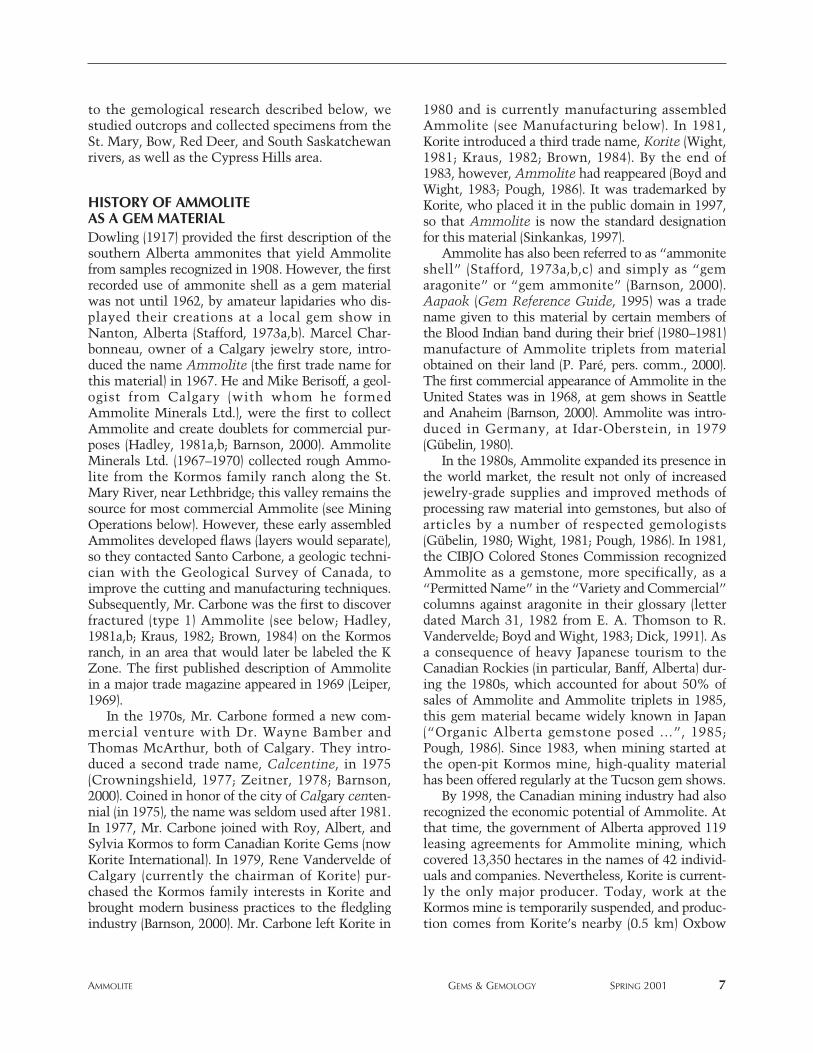
Figure 4. The open-pit Oxbow mine, located on theBlood Indian Reserve, currently is the main source of
Ammolite. An orange-colored backhoe, sittingdirectly on the K Zone (see text), is barely visible in
the center of the photograph. The St. Mary River (notvisible) runs along the base of the cliff in the dis-
tance. Note on the left side of the pit that the lightersoil represents alluvial deposits, whereas the under-
lying gray stratum is the Bearpaw Formation. Thecliff on the right caps the gray Bearpaw Formation
with tan-colored glacial sediments. Photo takenlooking north; courtesy of Korite International.
whose shells are now the source of Ammolite. Outcrops of the Bearpaw Formation are recognized
in the Canadian provinces of Alberta andSaskatchewan, and in the U.S. state of Montana,where the type locality was first described and namedafter the Bearpaw Mountains (Hatcher and Stanton,1903); the formation is known by a variety of othernames in other states and provinces. However, thereare no commercial occurrences of Ammolite outsideof Alberta, although several attempts have been madeto find such deposits (P. Paré, P. Evanson, and A.Ingelson, pers. comms., 2000).
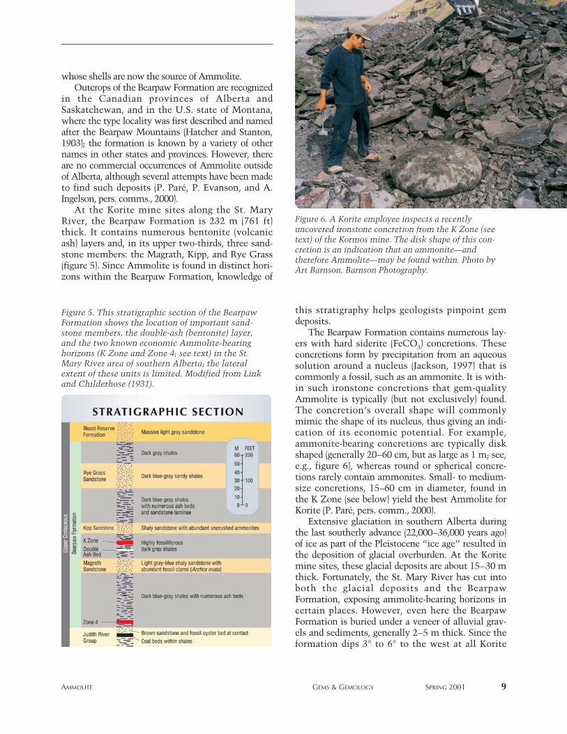
At the Korite mine sites along the St. MaryRiver, the Bearpaw Formation is 232 m (761 ft)thick. It contains numerous bentonite (volcanicash) layers and, in its upper two-thirds, three sand-stone members: the Magrath, Kipp, and Rye Grass(figure 5). Since Ammolite is found in distinct hori-zons within the Bearpaw Formation, knowledge of
this stratigraphy helps geologists pinpoint gemdeposits.
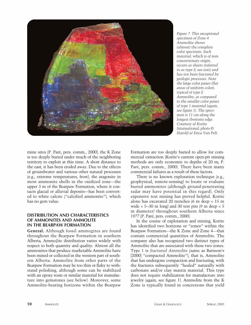
The Bearpaw Formation contains numerous lay-ers with hard siderite (FeCO3) concretions. Theseconcretions form by precipitation from an aqueoussolution around a nucleus (Jackson, 1997) that iscommonly a fossil, such as an ammonite. It is with-in such ironstone concretions that gem-qualityAmmolite is typically (but not exclusively) found.The concretion’s overall shape will commonlymimic the shape of its nucleus, thus giving an indi-cation of its economic potential. For example,ammonite-bearing concretions are typically diskshaped (generally 20–60 cm, but as large as 1 m; see,e.g., figure 6), whereas round or spherical concre-tions rarely contain ammonites. Small- to medium-size concretions, 15–60 cm in diameter, found inthe K Zone (see below) yield the best Ammolite forKorite (P. Paré, pers. comm., 2000).
Extensive glaciation in southern Alberta duringthe last southerly advance (22,000–36,000 years ago)of ice as part of the Pleistocene “ice age” resulted inthe deposition of glacial overburden. At the Koritemine sites, these glacial deposits are about 15–30 mthick. Fortunately, the St. Mary River has cut intoboth the glacial deposits and the BearpawFormation, exposing ammolite-bearing horizons incertain places. However, even here the BearpawFormation is buried under a veneer of alluvial grav-els and sediments, generally 2–5 m thick. Since theformation dips 3° to 6° to the west at all Korite
AMMOLITE GEMS & GEMOLOGY SPRING 2001 9
Figure 5. This stratigraphic section of the BearpawFormation shows the location of important sand-stone members, the double-ash (bentonite) layer,and the two known economic Ammolite-bearinghorizons (K Zone and Zone 4; see text) in the St.Mary River area of southern Alberta; the lateralextent of these units is limited. Modified from Linkand Childerhose (1931).
Figure 6. A Korite employee inspects a recentlyuncovered ironstone concretion from the K Zone (seetext) of the Kormos mine. The disk shape of this con-cretion is an indication that an ammonite—andtherefore Ammolite—may be found within. Photo byArt Barnson, Barnson Photography.
mine sites (P. Paré, pers. comm., 2000), the K Zoneis too deeply buried under much of the neighboringterritory to exploit at this time. A short distance tothe east, it has been eroded away. Due to the effectsof groundwater and various other natural processes(e.g., extreme temperatures, frost), the aragonite inmost ammonite shells in the oxidized zone—theupper 3 m of the Bearpaw Formation, where it con-tacts glacial or alluvial deposits—has been convert-ed to white calcite (“calcified ammonite”), whichhas no gem value.
DISTRIBUTION AND CHARACTERISTICS OF AMMONITES AND AMMOLITE IN THE BEARPAW FORMATIONGeneral. Although fossil ammonites are foundthroughout the Bearpaw Formation in southernAlberta, Ammolite distribution varies widely withrespect to both quantity and quality. Almost all theammonites that produce marketable Ammolite havebeen mined or collected in the western part of south-ern Alberta. Ammolite from other parts of theBearpaw Formation may be too thin or flaky to with-stand polishing, although some can be stabilizedwith an epoxy resin or similar material for manufac-ture into gemstones (see below). Moreover, someAmmolite-bearing horizons within the Bearpaw
Formation are too deeply buried to allow for com-mercial extraction (Korite’s current open-pit miningmethods are only economic to depths of 20 m; P.Paré, pers. comm., 2000). There have been manycommercial failures as a result of these factors.
There is no known exploration technique (e.g.,geophysical, remote-sensing) to locate or evaluateburied ammonites (although ground-penetratingradar may have potential in this regard). Onlyexpensive test mining has proved helpful. Koritealone has excavated 20 trenches (6 m deep × 15 mwide × 5–30 m long) and 30 test pits (9 m deep × 5m diameter) throughout southern Alberta since1977 (P. Paré, pers. comm., 2000).
In the course of exploration and mining, Koritehas identified two horizons or “zones” within theBearpaw Formation—the K Zone and Zone 4—thatcontain commercial quantities of Ammolite. Thecompany also has recognized two distinct types ofAmmolite that are associated with these two zones.Type 1 is fractured Ammolite (same as Barnson’s[2000] “compacted Ammolite”), that is, Ammolitethat has undergone compaction and fracturing, withthe fractures subsequently “healed” naturally withcarbonate and/or clay matrix material. This typedoes not require stabilization for manufacture intojewelry (again, see figure 1). Ammolite from the KZone is typically found in concretions that yield
10 AMMOLITE GEMS & GEMOLOGY SPRING 2001
Figure 7. This exceptionalspecimen of Zone 4Ammolite shows(almost) the completecolor spectrum. Suchmaterial, which is of non-concretionary origin,occurs as sheets (referredto as type 2; see text) andhas not been fractured bygeologic processes. Notethe large color panes (flatareas of uniform color),typical of type 2Ammolite, as comparedto the smaller color panesof type 1 material (again,see figure 1). The speci-men is 11 cm along thelongest (bottom) edge.Courtesy of KoriteInternational; photo ©Harold & Erica Van Pelt.
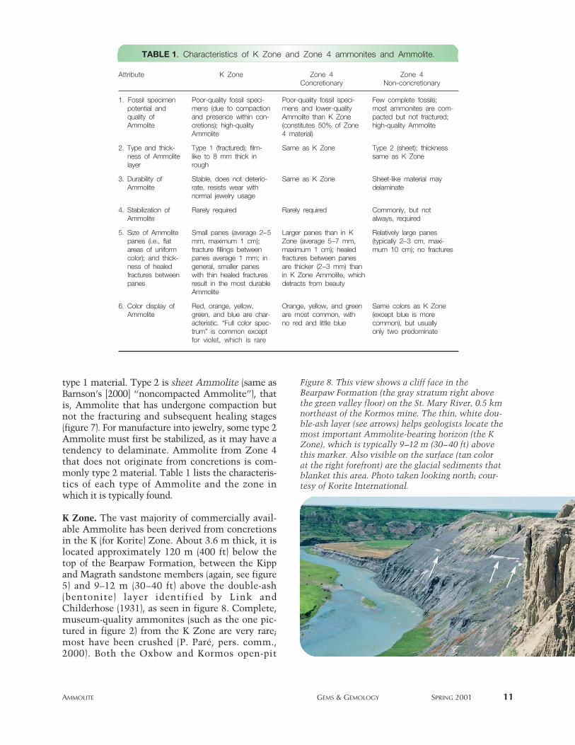
type 1 material. Type 2 is sheet Ammolite (same asBarnson’s [2000] “noncompacted Ammolite”), thatis, Ammolite that has undergone compaction butnot the fracturing and subsequent healing stages(figure 7). For manufacture into jewelry, some type 2Ammolite must first be stabilized, as it may have atendency to delaminate. Ammolite from Zone 4that does not originate from concretions is com-monly type 2 material. Table 1 lists the characteris-tics of each type of Ammolite and the zone inwhich it is typically found.
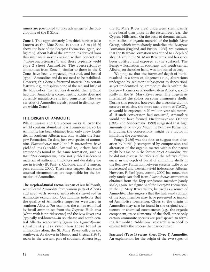
K Zone. The vast majority of commercially avail-able Ammolite has been derived from concretionsin the K (for Korite) Zone. About 3.6 m thick, it islocated approximately 120 m (400 ft) below thetop of the Bearpaw Formation, between the Kippand Magrath sandstone members (again, see figure5) and 9–12 m (30–40 ft) above the double-ash(bentonite) layer identified by Link andChilderhose (1931), as seen in figure 8. Complete,museum-quality ammonites (such as the one pic-tured in figure 2) from the K Zone are very rare;most have been crushed (P. Paré, pers. comm.,2000). Both the Oxbow and Kormos open-pit
AMMOLITE GEMS & GEMOLOGY SPRING 2001 11
TABLE 1. Characteristics of K Zone and Zone 4 ammonites and Ammolite.
Attribute K Zone Zone 4 Zone 4Concretionary Non-concretionary
1. Fossil specimen Poor-quality fossil speci- Poor-quality fossil speci- Few complete fossils; potential and mens (due to compaction mens and lower-quality most ammonites are com-quality of and presence within con- Ammolite than K Zone pacted but not fractured;Ammolite cretions); high-quality (constitutes 50% of Zone high-quality Ammolite
Ammolite 4 material)
2. Type and thick- Type 1 (fractured); film- Same as K Zone Type 2 (sheet); thicknessness of Ammolite like to 8 mm thick in same as K Zonelayer rough
3. Durability of Stable, does not deterio- Same as K Zone Sheet-like material may Ammolite rate, resists wear with delaminate
normal jewelry usage
4. Stabilization of Rarely required Rarely required Commonly, but notAmmolite always, required
5. Size of Ammolite Small panes (average 2–5 Larger panes than in K Relatively large panespanes (i.e., flat mm, maximum 1 cm); Zone (average 5–7 mm, (typically 2–3 cm, maxi-areas of uniform fracture fillings between maximum 1 cm); healed mum 10 cm); no fracturescolor); and thick- panes average 1 mm; in fractures between panes ness of healed general, smaller panes are thicker (2–3 mm) thanfractures between with thin healed fractures in K Zone Ammolite, whichpanes result in the most durable detracts from beauty
Ammolite
6. Color display of Red, orange, yellow, Orange, yellow, and green Same colors as K ZoneAmmolite green, and blue are char- are most common, with (except blue is more
acteristic. “Full color spec- no red and little blue common), but usually trum” is common except only two predominatefor violet, which is rare
Figure 8. This view shows a cliff face in theBearpaw Formation (the gray stratum right abovethe green valley floor) on the St. Mary River, 0.5 kmnortheast of the Kormos mine. The thin, white dou-ble-ash layer (see arrows) helps geologists locate themost important Ammolite-bearing horizon (the KZone), which is typically 9–12 m (30–40 ft) abovethis marker. Also visible on the surface (tan colorat the right forefront) are the glacial sediments thatblanket this area. Photo taken looking north; cour-tesy of Korite International.
mines are positioned to take advantage of the out-cropping of the K Zone.
Zone 4. This approximately 2-m-thick horizon (alsoknown as the Blue Zone) is about 4.5 m (15 ft)above the base of the Bearpaw Formation (again, seefigure 5). About half of the ammonites derived fromthis unit were never encased within concretions(“non-concretionary”), and these typically yieldtype 2 sheet Ammolite. The concretionaryammonites from Zone 4, similar to those in the KZone, have been compacted, fractured, and healed(type 1 Ammolite) and do not need to be stabilized.However, this Zone 4 fractured material has certainfeatures (e.g., it displays none of the red and little ofthe blue colors) that are less desirable than K Zonefractured Ammolite; consequently, Korite does notcurrently manufacture it into gemstones. The twovarieties of Ammolite are also found in distinct lay-ers within Zone 4.
THE ORIGIN OF AMMOLITEWhile Jurassic and Cretaceous rocks all over theworld contain abundant fossil ammonites, so farAmmolite has been obtained from only a few locali-ties in southern Alberta and only within the Bear-paw Formation. To date, just two species of ammo-nite, Placenticeras meeki and P. intercalare, haveyielded marketable Ammolite; other fossilammonoids found in the same formation, such asBaculites compressus, have not yielded iridescentmaterial of sufficient thickness and durability foruse in jewelry (P. Paré, S. Carbone, and P. Evanson,pers. comms., 2000). These facts suggest that someunusual circumstances are responsible for the for-mation of Ammolite.
The Depth-of-Burial Factor. As part of our fieldwork,we collected Ammolite from various parts of Albertaand met with several individuals involved inAmmolite exploration. Our findings indicate thatthe quality of Ammolite improves westward insouthern Alberta. For example, the colors exhibitedby fossil ammonites from the Cypress Hills area(white with faint iridescence) and the Bow River area(typically red-brown)—in southeast and south-cen-tral Alberta, respectively (again, see figure 3)—aresignificantly less vivid than those found inammonites along the St. Mary River valley in thesouthwest. As shown in Mossop and Shetsen (1994),rocks in the western part of southern Alberta (e.g.,
the St. Mary River area) underwent significantlymore burial than those in the eastern part (e.g., theCypress Hills area). On the basis of thermal matura-tion studies of organic material of the Judith RiverGroup, which immediately underlies the BearpawFormation (England and Bustin, 1986), we estimatethat the Bearpaw Formation was buried to a depth ofabout 4 km in the St. Mary River area (and has sincebeen uplifted and exposed at the surface). TheBearpaw Formation in southeast and south-centralAlberta, on the other hand, was not buried as deep.
We propose that the increased depth of burialresulted in a form of diagenesis (i.e., alterationsundergone by sediment subsequent to deposition),as yet unidentified, on ammonite shells within theBearpaw Formation of southwestern Alberta, specif-ically in the St. Mary River area. The diagenesisintensified the colors on some ammonite shells.During this process, however, the aragonite did notconvert to calcite, the more stable form of CaCO3,as would be expected in 70-million-year-old materi-al. If such conversion had occurred, Ammolitewould not have formed. Niedermayr and Oehner(1995) and Niedermayr (1999) suggested that highamounts of Fe and/or Mg in the Bearpaw Formation(including the concretions) might be a factor ininhibiting the conversion.
Pough (1986) was the first to suggest that alter-ation by burial (accompanied by compression andalteration of the organic matter within the nacre)might be a factor in the formation of Ammolite, buthe did not discuss the effects of the relative differ-ences in the depth of burial of ammonite shells inthe Bearpaw Formation between eastern (little or noiridescence) and western (vivid iridescence) Alberta.However, P. Paré (pers. comm., 2000) has noted thatonly rarely can shell from Placenticeras ammonitesobtained from the Kipp sandstone member (sandyshale; again, see figure 5) of the Bearpaw Formation,in the St. Mary River valley, be used as a source ofAmmolite. This suggests that the high sand contentof the Kipp member may have prevented or imped-ed Ammolite formation. Clues to the origin ofAmmolite may also be found in the original archi-tecture or chemical constituents (e.g., the organiccomponent, trace elements) of the shell, since onlycertain ammonite species are predisposed to form-ing Ammolite. Additional research is needed toexplain fully the process that has occurred.
Fractured (Type 1) versus Sheet (Type 2) Ammolite.An explanation for the origin of the two types of
12 AMMOLITE GEMS & GEMOLOGY SPRING 2001
Ammolite, fractured (type 1) and sheet (type 2), canbe found in the rate and extent of sediment infill intoammonite shells following the death of the animal.After Placenticeras ammonites died, their shells sankto the bottom of the Bearpaw Sea. Some of theseshells were quickly buried, with little or no sedimentfilling the empty shell chambers. Their internallyunsupported shells were subsequently compactedand fractured (and later healed), which resulted intype 1 Ammolite (K Zone material; again, see figure1). However, it is likely that the chambers in thoseshells that were not buried rapidly would have filledwith sediment, so that the ammonite shell was inter-nally supported. Such shells would resist fracturingduring compaction, thus giving rise to type 2Ammolite (sheet material characteristic of Zone 4;again, see figure 7). Ward et al. (1982) were the first tonote that the lack of sediment infill into the emptychambers of Placenticeras shells following burialresulted in a high ratio of compacted shells in severalzones; however, they did not extend this observationto the origin of fractured type 1 Ammolite within theBearpaw Formation. Type 1 Ammolite is usually (butnot always) found within ironstone concretions,whereas type 2 Ammolite is not (again, see table 1),which suggests that concretions play a role in devel-oping the type 1 material.
MINING OPERATIONSSurface Collecting. Since the early 1960s, Ammolitehas been collected by amateurs and small commer-cial lapidaries from the vicinity of the St. MaryRiver (e.g., Stafford, 1973a). These finds occur in theriverbed and along the valley walls, whereammonites are exposed by erosion. Subsequently,Ammolite was discovered in the gravel bars ofnumerous other rivers throughout southern Albertawhere the Bearpaw Formation is exposed (again, seefigure 3); mining claims currently are held on theBow, Little Bow, Oldman, and Red Deer rivers. Weestimate that 5%–7% of current Ammolite produc-tion is derived from surface-collected material, allby small producers. An additional 2% of the total isobtained by small producers from small test pits inthe Bearpaw Formation. Similarly, about 1% ofKorite’s production is from concretions collected onthe surface in the St. Mary River valley (P. Paré,pers. comm., 2000).
Open-pit Mines. Only two mines—Kormos andOxbow—have produced gem-quality Ammolite in
significant quantities. Both are open-pit operationson the banks of the St. Mary River (again, see figures3 and 4). Essentially all (99%) of Korite’s productionhas come from open-pit mines, with the remainderfrom the surface source mentioned above (P. Paré,pers. comm., 2000). The Kormos mine was activefrom 1983 to 1994; since then, operations have beensuspended, although long-range plans are to reacti-vate the mine. Production at the Oxbow mine start-ed in 1994 and has continued to the present.
In recent years, Korite has mined between 2 and5 acres annually to achieve a production of about57,000 finished pieces of Ammolite and assembledAmmolite gems per year (P. Paré, pers. comm.,2001). Between 1983 and 1999, Korite excavated 40acres of land, of which 35 acres have been restoredto their natural state.
Mining Methods. Initially, the topsoil, sand, andgravel layers are stripped and stockpiled for later sitereclamation. The underlying Bearpaw Formation isthen excavated with a large backhoe (again, see fig-ure 4). Blasting is not required because the shalesare so easily worked. Mining is conducted fromMarch through November, as winter operations ofthis type are difficult in Canada.
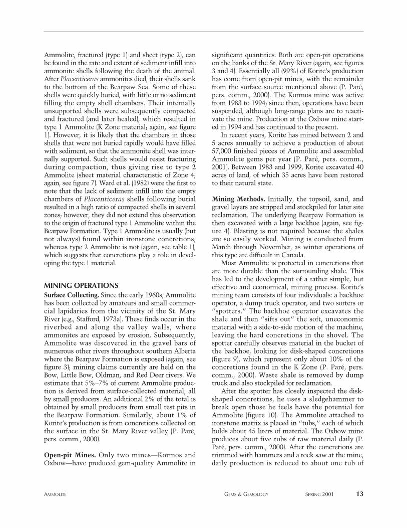
Most Ammolite is protected in concretions thatare more durable than the surrounding shale. Thishas led to the development of a rather simple, buteffective and economical, mining process. Korite’smining team consists of four individuals: a backhoeoperator, a dump truck operator, and two sorters or“spotters.” The backhoe operator excavates theshale and then “sifts out” the soft, uneconomicmaterial with a side-to-side motion of the machine,leaving the hard concretions in the shovel. Thespotter carefully observes material in the bucket ofthe backhoe, looking for disk-shaped concretions(figure 9), which represent only about 10% of theconcretions found in the K Zone (P. Paré, pers.comm., 2000). Waste shale is removed by dumptruck and also stockpiled for reclamation.
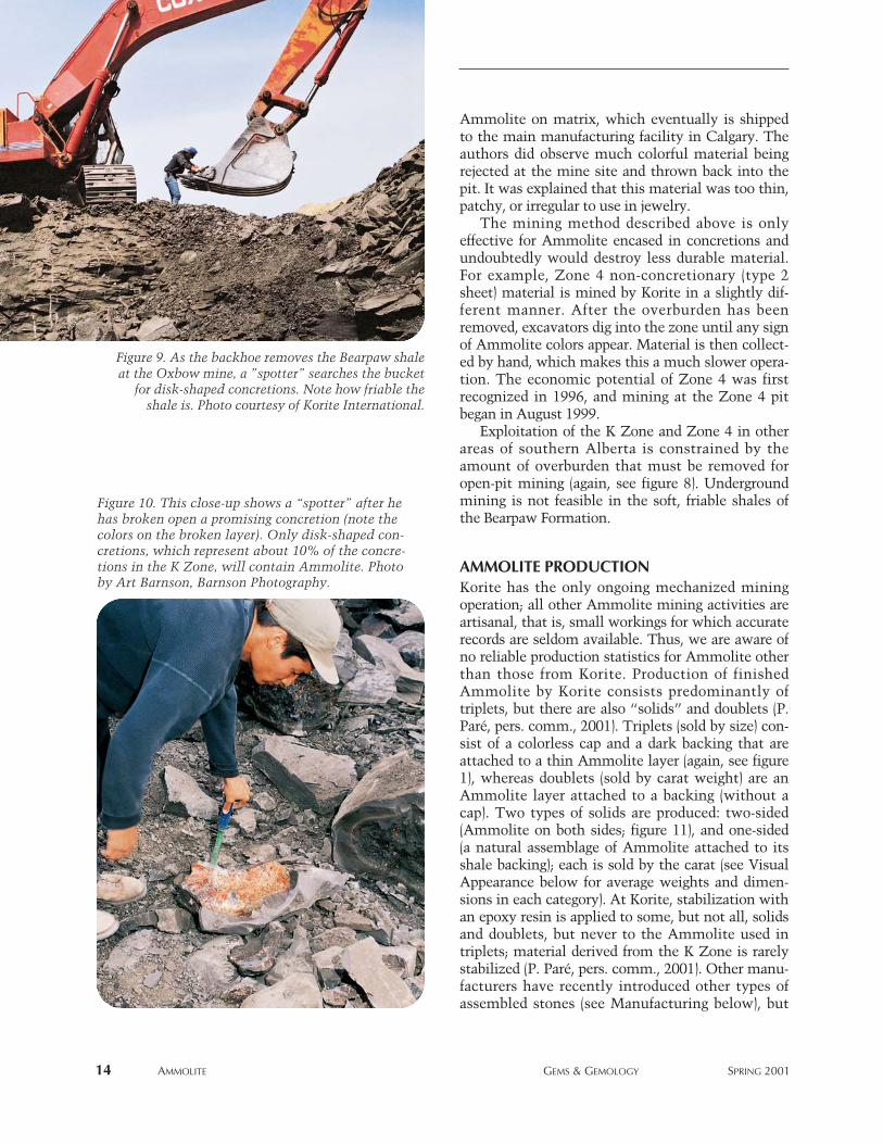
After the spotter has closely inspected the disk-shaped concretions, he uses a sledgehammer tobreak open those he feels have the potential forAmmolite (figure 10). The Ammolite attached toironstone matrix is placed in “tubs,” each of whichholds about 45 liters of material. The Oxbow mineproduces about five tubs of raw material daily (P.Paré, pers. comm., 2000). After the concretions aretrimmed with hammers and a rock saw at the mine,daily production is reduced to about one tub of
AMMOLITE GEMS & GEMOLOGY SPRING 2001 13
Ammolite on matrix, which eventually is shippedto the main manufacturing facility in Calgary. Theauthors did observe much colorful material beingrejected at the mine site and thrown back into thepit. It was explained that this material was too thin,patchy, or irregular to use in jewelry.
The mining method described above is onlyeffective for Ammolite encased in concretions andundoubtedly would destroy less durable material.For example, Zone 4 non-concretionary (type 2sheet) material is mined by Korite in a slightly dif-ferent manner. After the overburden has beenremoved, excavators dig into the zone until any signof Ammolite colors appear. Material is then collect-ed by hand, which makes this a much slower opera-tion. The economic potential of Zone 4 was firstrecognized in 1996, and mining at the Zone 4 pitbegan in August 1999.
Exploitation of the K Zone and Zone 4 in otherareas of southern Alberta is constrained by theamount of overburden that must be removed foropen-pit mining (again, see figure 8). Undergroundmining is not feasible in the soft, friable shales ofthe Bearpaw Formation.
AMMOLITE PRODUCTIONKorite has the only ongoing mechanized miningoperation; all other Ammolite mining activities areartisanal, that is, small workings for which accuraterecords are seldom available. Thus, we are aware ofno reliable production statistics for Ammolite otherthan those from Korite. Production of finishedAmmolite by Korite consists predominantly oftriplets, but there are also “solids” and doublets (P.Paré, pers. comm., 2001). Triplets (sold by size) con-sist of a colorless cap and a dark backing that areattached to a thin Ammolite layer (again, see figure1), whereas doublets (sold by carat weight) are anAmmolite layer attached to a backing (without acap). Two types of solids are produced: two-sided(Ammolite on both sides; figure 11), and one-sided(a natural assemblage of Ammolite attached to itsshale backing); each is sold by the carat (see VisualAppearance below for average weights and dimen-sions in each category). At Korite, stabilization withan epoxy resin is applied to some, but not all, solidsand doublets, but never to the Ammolite used intriplets; material derived from the K Zone is rarelystabilized (P. Paré, pers. comm., 2001). Other manu-facturers have recently introduced other types ofassembled stones (see Manufacturing below), but
14 AMMOLITE GEMS & GEMOLOGY SPRING 2001
Figure 10. This close-up shows a “spotter” after hehas broken open a promising concretion (note thecolors on the broken layer). Only disk-shaped con-cretions, which represent about 10% of the concre-tions in the K Zone, will contain Ammolite. Photoby Art Barnson, Barnson Photography.
Figure 9. As the backhoe removes the Bearpaw shaleat the Oxbow mine, a ”spotter” searches the bucket
for disk-shaped concretions. Note how friable theshale is. Photo courtesy of Korite International.
their impact on overall Ammolite availability hasnot yet been felt.
Major production began in 1983, with the open-ing of the Kormos mine. That first year, 12,211 fin-ished pieces were fashioned (12,004 Ammolitetriplets, 183 one-sided solids, and 24 two-sidedsolids; none of this material was stabilized) from20,500 tonnes of excavated shale (P. Paré, pers.comm., 2001). However, much of this early produc-tion included low-grade Ammolite that would nothave been manufactured into gems in recent years(P. Paré, pers. comm., 2001). Some reports of earlyKorite production (“Ammolite. New gems from…”,1984; “Organic Alberta gemstone posed …”, 1985;Vandervelde, 1993) suggested that less than 6,000tonnes of shale was excavated in 1983, but this isnot correct (P. Paré, pers. comm., 2001). Korite’sproduction in 1999 (the most recent year for whichKorite made data available to the authors), consistedof 55,000 Ammolite triplets, 1,500 Ammolite dou-blets (about 50% stabilized), 500 one-sided solids(about 50% stabilized), and only 25 two-sided solids(none stabilized); for a total of 57,025 finishedstones (P. Paré, pers. comm., 2001). This productionwas derived primarily from the Oxbow mine, withthe exception of small amounts from the Zone 4mine and surface-collected material. At present, the
Zone 4 mine contributes about 10% by volume, butonly 5% by value, to Korite’s overall production (P.Paré, pers. comm., 2001). The authors believe thatthe Korite operations represent about 90% of theproduction throughout Alberta. As such, we esti-mate that the total annual production of Ammolite(all categories) is currently more than 63,000 fin-ished stones.
Huge amounts of rock are mined to obtain a rel-atively small amount of gem-quality Ammolite. In1999, from 165,000 tonnes of excavated shale only105,000 carats (21 kg) of Ammolite solids andassembled gemstones (including the backings butnot the caps) were obtained (P. Paré, pers. comm.,2001). This is equivalent to a mere 0.64 ct per tonneof shale. Because the Ammolite layer in an averagetriplet is only 0.1 mm thick, the actual finishedcarat weight/tonne of Ammolite is, therefore, con-siderably less once the backing weight is subtracted.
STABILIZATION OF AMMOLITEStabilization—that is, impregnation of the materialunder pressure with an epoxy or other substance—is usually required to strengthen type 2 (sheet)Ammolite so that it can be manufactured into jew-elry as solids or doublets. (As stated above, the
AMMOLITE GEMS & GEMOLOGY SPRING 2001 15
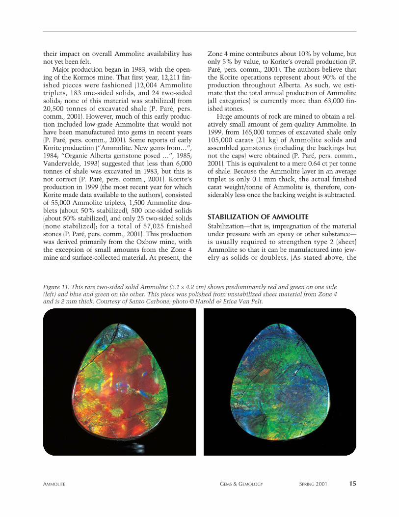
Figure 11. This rare two-sided solid Ammolite (3.1 × 4.2 cm) shows predominantly red and green on one side(left) and blue and green on the other. This piece was polished from unstabilized sheet material from Zone 4and is 2 mm thick. Courtesy of Santo Carbone; photo © Harold & Erica Van Pelt.
Ammolite incorporated into triplets is not stabi-lized.) Although it is likely that some Ammolitewas stabilized and sold as early as the 1970s (see,e.g., Sinkankas, 1997), details of such treatments are
lacking. Koivula and Kammerling (1991) were thefirst to document the stabilization of Ammolite,specifically a plastic impregnation that was used asearly as 1989.
Korite began stabilizing some type 2 (sheet)Ammolite from Zone 4 in 1998. Before fashioning,Korite impregnates the rough material under pres-sure (1500 psi) by forcing a commercially availablepolymer (an epoxy resin) into the Ammolite layerswith nitrogen gas (P. Paré, pers. comm., 2000).Other manufacturers may use different proceduresand materials.
During the stabilization process, the entire sam-ple is immersed in polymer. Subsequent polishingremoves the epoxy on the surface, and the onlyremaining epoxy is between the layers. We studiedsix such specimens by viewing them microscopically(incident illumination) on their polished edges. It waspossible to recognize the impregnation, though withdifficulty, at magnifications greater than 30×. Theimpregnation appears as very thin seams of epoxybetween the layers, and as small epoxy-filled voids.
Approximately 50% of the Ammolite solids anddoublets that Korite placed on the market in 1999were stabilized. Korite sells stabilized Ammolite forbetween one-third to one-half the price of untreatedmaterial of equivalent grade (P. Paré, pers. comm.,2000). The authors believe that perhaps one-third ofthe non-Korite production is also stabilized in someway, since it is mainly derived from surface-collect-ed sheet material.
Some color enhancement of Ammolite tripletshas been reported by Barnson (2000), where tripletbackings (see Manufacturing below) are paintedblue, green, or pink to enhance otherwise poorlycolored Ammolite. We could not confirm use of thistechnique (P. Paré and S. Carbone, pers. comms.,2001). Other enhancement techniques that areeffective with some gemstones, such as heat treat-ment and irradiation, are not applied to Ammoliteas they would damage the material.
MANUFACTURINGEarly descriptions of Ammolite manufacturing proce-dures, which were based on surface-collected materi-als (Stafford, 1973b,c; Jarand, 1982), are of historicalinterest only; for example, freeforms are no longertumbled in sawdust. Further, early Ammolite tripletswere made with surface-collected type 2 (sheet)Ammolite; many of these early gems tended to sepa-rate along the glued layers. Santo Carbone was the
16 AMMOLITE GEMS & GEMOLOGY SPRING 2001
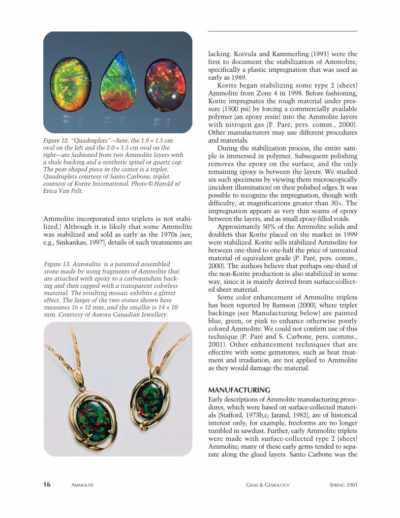
Figure 13. Auroralite is a patented assembledstone made by using fragments of Ammolite thatare attached with epoxy to a carborundum back-ing and then capped with a transparent colorlessmaterial. The resulting mosaic exhibits a glittereffect. The larger of the two stones shown heremeasures 16 × 12 mm, and the smaller is 14 × 10mm. Courtesy of Aurora Canadian Jewellery.
Figure 12. “Quadruplets”—here, the 1.9 × 1.5 cmoval on the left and the 2.0 × 1.5 cm oval on theright—are fashioned from two Ammolite layers witha shale backing and a synthetic spinel or quartz cap.The pear-shaped piece in the center is a triplet.Quadruplets courtesy of Santo Carbone; tripletcourtesy of Korite International. Photo © Harold &Erica Van Pelt.
first to correct these problems and perfect the manu-facturing techniques that are now used to producehigh-quality assembled gems. Today, the modernmanufacturing facilities of Korite in Calgary, whichemploys about 20 full-time cutters (about 50 staffmembers total), dominate the production ofAmmolite for the world market, although there areseveral smaller operations throughout Alberta.
Rough Ammolite that is sufficiently thick anddurable for manufacture into solids goes throughthe following steps: slabbing; trimming; stabilizing,if necessary; grinding to optimum colors; polishing;and shaping. Note that the cutter will constantlygrind a piece of Ammolite until it shows the mostattractive color display; this delicate techniquetakes years of experience to perfect—too muchgrinding could destroy a good color suite and pat-tern. Material that is made into triplets (again, seefigure 1) goes through a similar set of early steps,but after a first grinding to reach optimal colors (theAmmolite will still be relatively thick), a spinel or
quartz cap is attached with epoxy to the Ammolite,the back of the gem material is ground again toreduce thickness, and a piece of shale (typicallyfrom the Bearpaw Formation) that has been coatedwith lampblack is attached with epoxy to form abacking. A final trimming provides calibrated sizes.Using much the same process, Korite will attach anatural shale backing to polished pieces ofAmmolite that are too thin and fragile for use assolids to create doublets. For some of his assembledstones, Mr. Carbone uses two individual Ammolitelayers together with the backing and the cap (form-ing an Ammolite “quadruplet”), which increasesthe quantity and intensity of colors in the finishedpiece (see figure 12). Barnson (2000) provides step-by-step details of the manufacturing process.
Mr. Carbone also creates a unique mosaic-likeAmmolite “triplet” that has been marketed exclu-sively since 1997 by Aurora Canadian Jewellery asAuroralite (figure 13). These triplets have a glittereffect produced by a patented process (Carbone,1991) in which multi-colored fragments ofAmmolite (0.5–3 mm wide) are attached withepoxy to a synthetic spinel or quartz cap. Airtrapped in the epoxy is removed in a vacuum unitand then the cap is placed in a preheated oven toharden the epoxy to a gel-like state. At this point,grains of carborundum are sprinkled on the epoxy toform the base. Recently, Johnson et al. (2000)described these triplets, which Korite had providedfor examination and were erroneously attributed totheir mining operation.
In recent years, other innovative uses havebeen found for material that is not suited for man-ufacture into solids or assembled stones. Forexample, mosaics of small Ammolite fragmentshave been cemented into watch faces and otherforms of jewelry.
QUALITY GRADING OF AMMOLITEAlthough an internationally accepted grading sys-tem for Ammolite does not exist, Korite has devel-oped its own in-house grading system. A number ofabbreviated versions of this same system have beenpublished (Barnson, 1996; “Gemstone unique toCanada …,” 1999; Barnson, 2000).
There are six recognized grades of Ammolite asdescribed in table 2: Extra Fine, Fine, Good, Fair,Poor, and Commercial (which correspond toKorite’s AA, A+, A, A-, B, and C). The three factorsin determining the grade of a polished (unmounted)
AMMOLITE GEMS & GEMOLOGY SPRING 2001 17
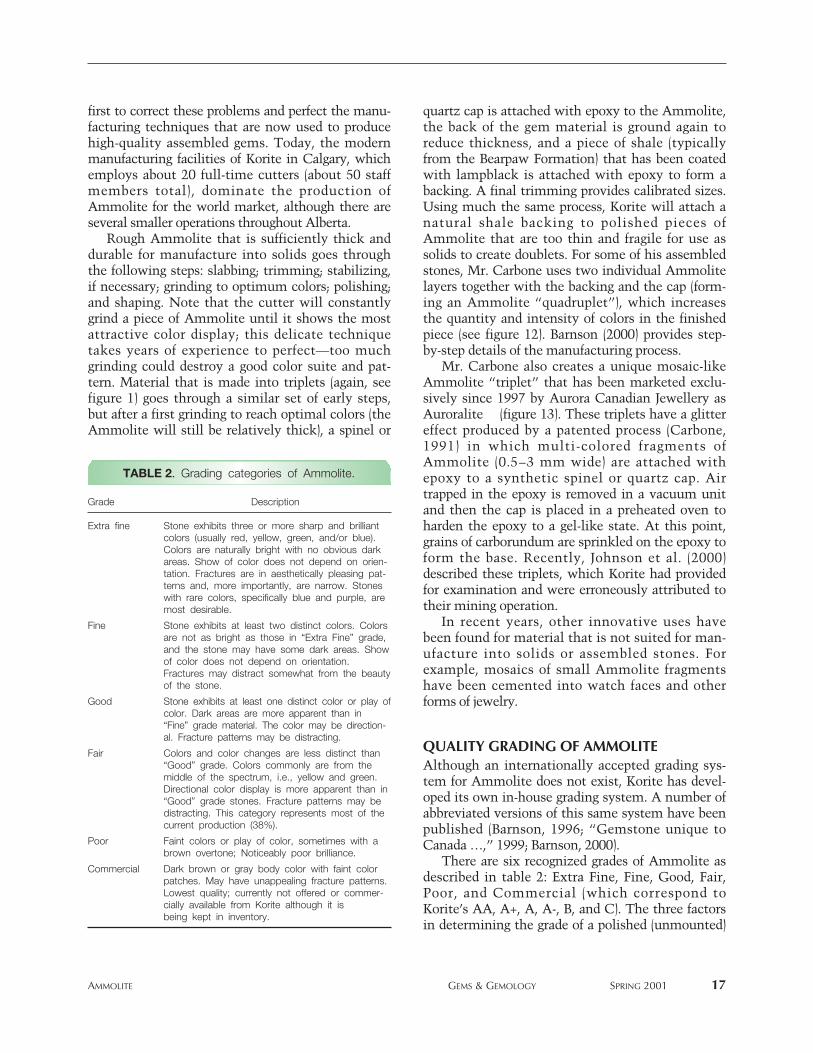
TABLE 2. Grading categories of Ammolite.
Grade Description
Extra fine Stone exhibits three or more sharp and brilliantcolors (usually red, yellow, green, and/or blue).Colors are naturally bright with no obvious darkareas. Show of color does not depend on orien-tation. Fractures are in aesthetically pleasing pat-terns and, more importantly, are narrow. Stoneswith rare colors, specifically blue and purple, aremost desirable.
Fine Stone exhibits at least two distinct colors. Colorsare not as bright as those in “Extra Fine” grade,and the stone may have some dark areas. Showof color does not depend on orientation.Fractures may distract somewhat from the beautyof the stone.
Good Stone exhibits at least one distinct color or play ofcolor. Dark areas are more apparent than in“Fine” grade material. The color may be direction-al. Fracture patterns may be distracting.
Fair Colors and color changes are less distinct than“Good” grade. Colors commonly are from themiddle of the spectrum, i.e., yellow and green.Directional color display is more apparent than in“Good” grade stones. Fracture patterns may bedistracting. This category represents most of thecurrent production (38%).
Poor Faint colors or play of color, sometimes with abrown overtone; Noticeably poor brilliance.
Commercial Dark brown or gray body color with faint colorpatches. May have unappealing fracture patterns.Lowest quality; currently not offered or commer-cially available from Korite although it isbeing kept in inventory.
Ammolite solid or assembled stone are: color rangeand display, intensity of iridescence, and pattern.The grade distribution, as a percent of Korite’s totalsales for 2000 (P. Paré, pers. comm., 2001), was:Extra Fine—6%, Fine—5%, Good—21%, Fair—38%, and Poor—30% (“Commercial” grade materi-al was not sold).
Color Range and Display. In general, the more col-ors displayed, the higher the grade. Thus, stonesthat exhibit the full color spectrum, and especiallyblue and violet or purple (the latter is particularlyrare), are most desirable. Stones that exhibit onlyone color, especially entirely red or brown (which,after white, are the most common colors found onBearpaw Formation ammonite), are less desirable.
Intensity of Iridescence. The ideal Ammolite showssharp color sections and bright hues. Although somestones exhibit a full color spectrum, the colors mayappear dark when illuminated from different direc-tions. Such a directional display of color detractsfrom the beauty, and hence the value, of a stone andcan generate a grade no higher than Fine.
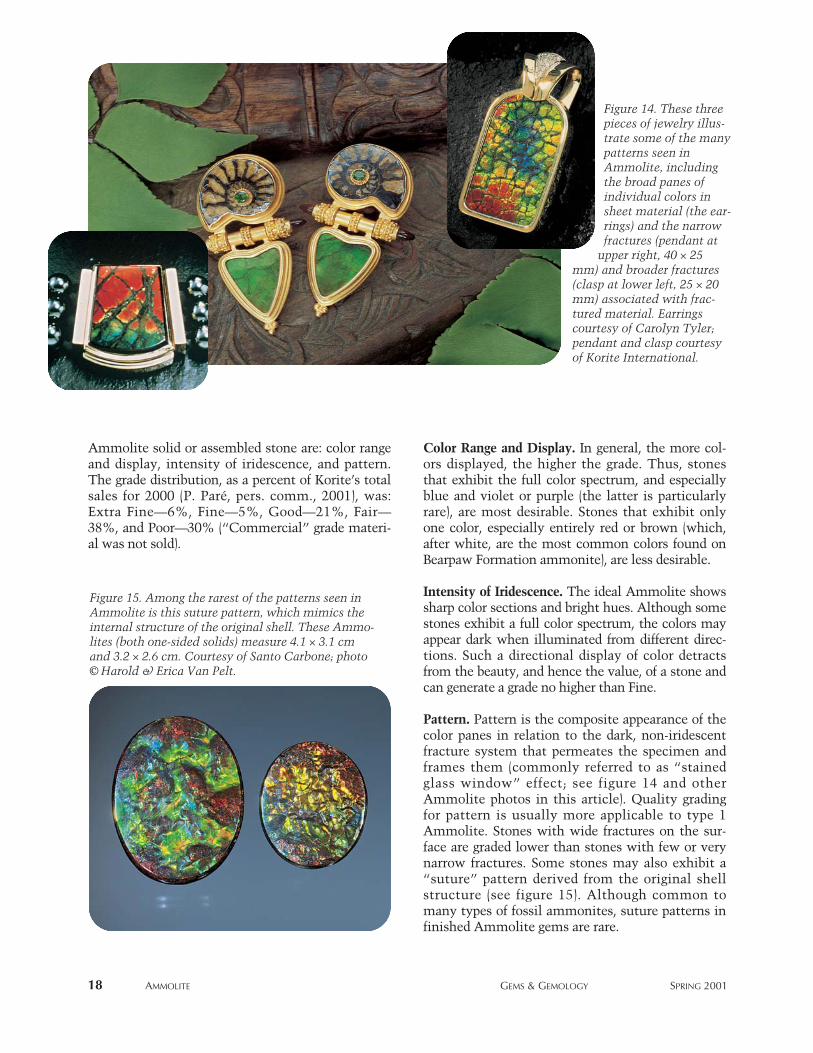
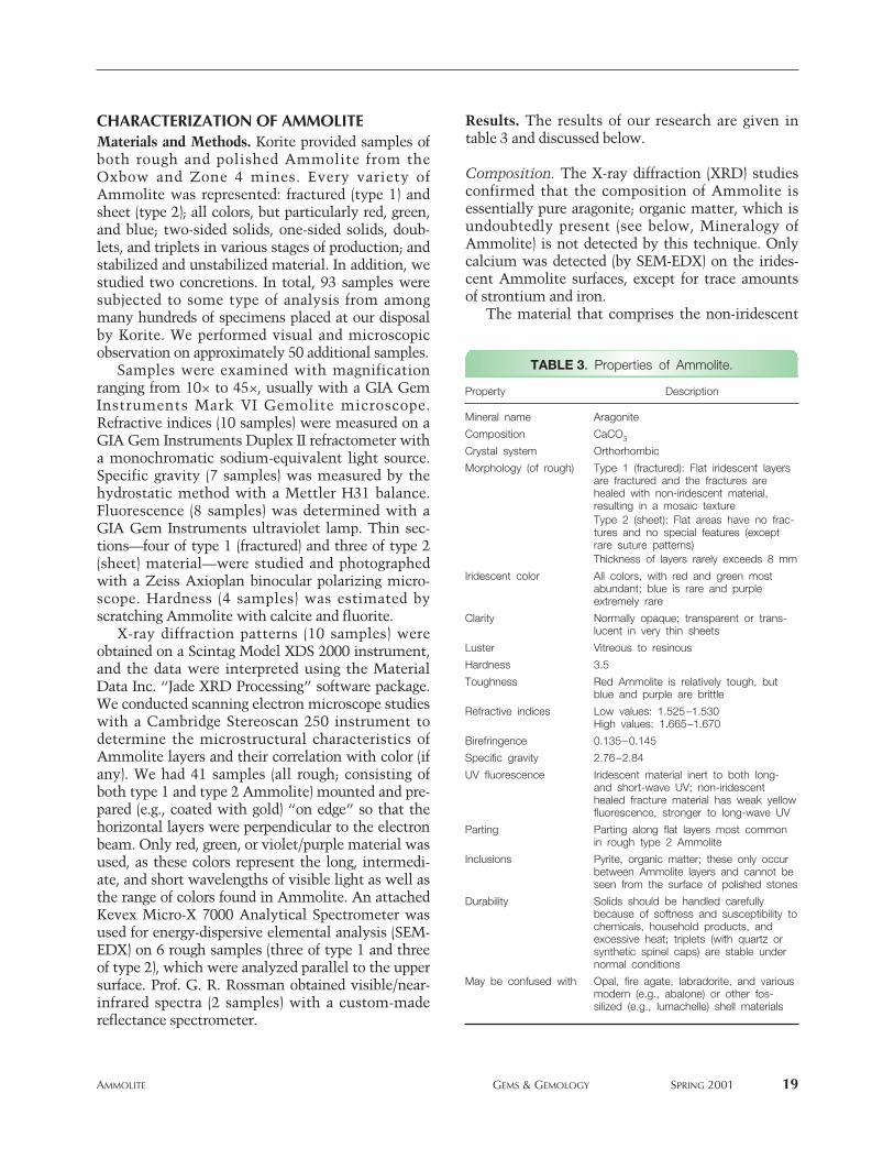
Pattern. Pattern is the composite appearance of thecolor panes in relation to the dark, non-iridescentfracture system that permeates the specimen andframes them (commonly referred to as “stainedglass window” effect; see figure 14 and otherAmmolite photos in this article). Quality gradingfor pattern is usually more applicable to type 1Ammolite. Stones with wide fractures on the sur-face are graded lower than stones with few or verynarrow fractures. Some stones may also exhibit a“suture” pattern derived from the original shellstructure (see figure 15). Although common tomany types of fossil ammonites, suture patterns infinished Ammolite gems are rare.
18 AMMOLITE GEMS & GEMOLOGY SPRING 2001
Figure 15. Among the rarest of the patterns seen inAmmolite is this suture pattern, which mimics theinternal structure of the original shell. These Ammo-lites (both one-sided solids) measure 4.1 × 3.1 cmand 3.2 × 2.6 cm. Courtesy of Santo Carbone; photo© Harold & Erica Van Pelt.
Figure 14. These threepieces of jewelry illus-trate some of the manypatterns seen inAmmolite, includingthe broad panes ofindividual colors insheet material (the ear-rings) and the narrowfractures (pendant at
upper right, 40 × 25mm) and broader fractures(clasp at lower left, 25 × 20mm) associated with frac-tured material. Earringscourtesy of Carolyn Tyler;pendant and clasp courtesyof Korite International.
CHARACTERIZATION OF AMMOLITEMaterials and Methods. Korite provided samples ofboth rough and polished Ammolite from theOxbow and Zone 4 mines. Every variety ofAmmolite was represented: fractured (type 1) andsheet (type 2); all colors, but particularly red, green,and blue; two-sided solids, one-sided solids, doub-lets, and triplets in various stages of production; andstabilized and unstabilized material. In addition, westudied two concretions. In total, 93 samples weresubjected to some type of analysis from amongmany hundreds of specimens placed at our disposalby Korite. We performed visual and microscopicobservation on approximately 50 additional samples.
Samples were examined with magnificationranging from 10× to 45×, usually with a GIA GemInstruments Mark VI Gemolite microscope.Refractive indices (10 samples) were measured on aGIA Gem Instruments Duplex II refractometer witha monochromatic sodium-equivalent light source.Specific gravity (7 samples) was measured by thehydrostatic method with a Mettler H31 balance.Fluorescence (8 samples) was determined with aGIA Gem Instruments ultraviolet lamp. Thin sec-tions—four of type 1 (fractured) and three of type 2(sheet) material—were studied and photographedwith a Zeiss Axioplan binocular polarizing micro-scope. Hardness (4 samples) was estimated byscratching Ammolite with calcite and fluorite.
X-ray diffraction patterns (10 samples) wereobtained on a Scintag Model XDS 2000 instrument,and the data were interpreted using the MaterialData Inc. “Jade XRD Processing” software package.We conducted scanning electron microscope studieswith a Cambridge Stereoscan 250 instrument todetermine the microstructural characteristics ofAmmolite layers and their correlation with color (ifany). We had 41 samples (all rough; consisting ofboth type 1 and type 2 Ammolite) mounted and pre-pared (e.g., coated with gold) “on edge” so that thehorizontal layers were perpendicular to the electronbeam. Only red, green, or violet/purple material wasused, as these colors represent the long, intermedi-ate, and short wavelengths of visible light as well asthe range of colors found in Ammolite. An attachedKevex Micro-X 7000 Analytical Spectrometer wasused for energy-dispersive elemental analysis (SEM-EDX) on 6 rough samples (three of type 1 and threeof type 2), which were analyzed parallel to the uppersurface. Prof. G. R. Rossman obtained visible/near-infrared spectra (2 samples) with a custom-madereflectance spectrometer.
Results. The results of our research are given intable 3 and discussed below.
Composition. The X-ray diffraction (XRD) studiesconfirmed that the composition of Ammolite isessentially pure aragonite; organic matter, which isundoubtedly present (see below, Mineralogy ofAmmolite) is not detected by this technique. Onlycalcium was detected (by SEM-EDX) on the irides-cent Ammolite surfaces, except for trace amountsof strontium and iron.
The material that comprises the non-iridescent
AMMOLITE GEMS & GEMOLOGY SPRING 2001 19
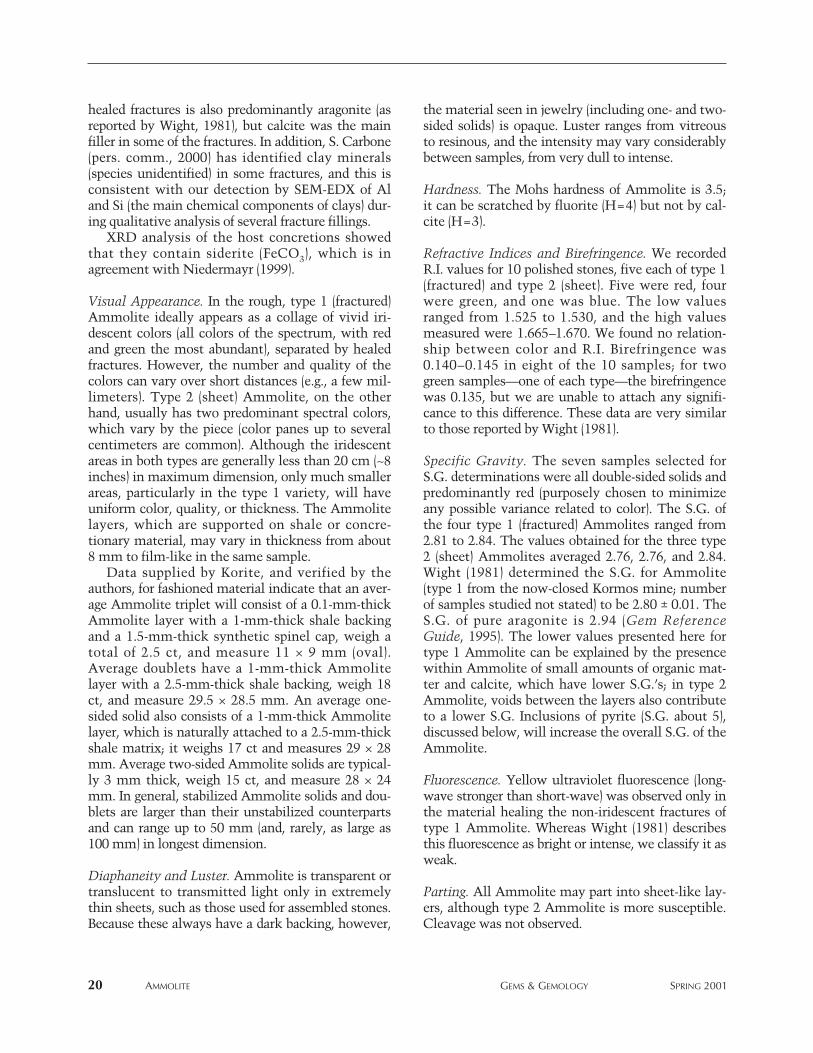
TABLE 3. Properties of Ammolite.
Property Description
Mineral name Aragonite
Composition CaCO3
Crystal system Orthorhombic
Morphology (of rough) Type 1 (fractured): Flat iridescent layersare fractured and the fractures arehealed with non-iridescent material,resulting in a mosaic textureType 2 (sheet): Flat areas have no frac-tures and no special features (exceptrare suture patterns)Thickness of layers rarely exceeds 8 mm
Iridescent color All colors, with red and green mostabundant; blue is rare and purpleextremely rare
Clarity Normally opaque; transparent or trans-lucent in very thin sheets
Luster Vitreous to resinous
Hardness 3.5
Toughness Red Ammolite is relatively tough, butblue and purple are brittle
Refractive indices Low values: 1.525–1.530High values: 1.665–1.670
Birefringence 0.135–0.145
Specific gravity 2.76–2.84
UV fluorescence Iridescent material inert to both long-and short-wave UV; non-iridescenthealed fracture material has weak yellowfluorescence, stronger to long-wave UV
Parting Parting along flat layers most commonin rough type 2 Ammolite
Inclusions Pyrite, organic matter; these only occurbetween Ammolite layers and cannot beseen from the surface of polished stones
Durability Solids should be handled carefullybecause of softness and susceptibility tochemicals, household products, andexcessive heat; triplets (with quartz orsynthetic spinel caps) are stable undernormal conditions
May be confused with Opal, fire agate, labradorite, and variousmodern (e.g., abalone) or other fos-silized (e.g., lumachelle) shell materials
healed fractures is also predominantly aragonite (asreported by Wight, 1981), but calcite was the mainfiller in some of the fractures. In addition, S. Carbone(pers. comm., 2000) has identified clay minerals(species unidentified) in some fractures, and this isconsistent with our detection by SEM-EDX of Aland Si (the main chemical components of clays) dur-ing qualitative analysis of several fracture fillings.
XRD analysis of the host concretions showedthat they contain siderite (FeCO3), which is inagreement with Niedermayr (1999).
Visual Appearance. In the rough, type 1 (fractured)Ammolite ideally appears as a collage of vivid iri-descent colors (all colors of the spectrum, with redand green the most abundant), separated by healedfractures. However, the number and quality of thecolors can vary over short distances (e.g., a few mil-limeters). Type 2 (sheet) Ammolite, on the otherhand, usually has two predominant spectral colors,which vary by the piece (color panes up to severalcentimeters are common). Although the iridescentareas in both types are generally less than 20 cm (~8inches) in maximum dimension, only much smallerareas, particularly in the type 1 variety, will haveuniform color, quality, or thickness. The Ammolitelayers, which are supported on shale or concre-tionary material, may vary in thickness from about8 mm to film-like in the same sample.
Data supplied by Korite, and verified by theauthors, for fashioned material indicate that an aver-age Ammolite triplet will consist of a 0.1-mm-thickAmmolite layer with a 1-mm-thick shale backingand a 1.5-mm-thick synthetic spinel cap, weigh atotal of 2.5 ct, and measure 11 × 9 mm (oval).Average doublets have a 1-mm-thick Ammolitelayer with a 2.5-mm-thick shale backing, weigh 18ct, and measure 29.5 × 28.5 mm. An average one-sided solid also consists of a 1-mm-thick Ammolitelayer, which is naturally attached to a 2.5-mm-thickshale matrix; it weighs 17 ct and measures 29 × 28mm. Average two-sided Ammolite solids are typical-ly 3 mm thick, weigh 15 ct, and measure 28 × 24mm. In general, stabilized Ammolite solids and dou-blets are larger than their unstabilized counterpartsand can range up to 50 mm (and, rarely, as large as100 mm) in longest dimension.
Diaphaneity and Luster. Ammolite is transparent ortranslucent to transmitted light only in extremelythin sheets, such as those used for assembled stones.Because these always have a dark backing, however,
the material seen in jewelry (including one- and two-sided solids) is opaque. Luster ranges from vitreousto resinous, and the intensity may vary considerablybetween samples, from very dull to intense.
Hardness. The Mohs hardness of Ammolite is 3.5;it can be scratched by fluorite (H=4) but not by cal-cite (H=3).
Refractive Indices and Birefringence. We recordedR.I. values for 10 polished stones, five each of type 1(fractured) and type 2 (sheet). Five were red, fourwere green, and one was blue. The low valuesranged from 1.525 to 1.530, and the high valuesmeasured were 1.665–1.670. We found no relation-ship between color and R.I. Birefringence was0.140–0.145 in eight of the 10 samples; for twogreen samples—one of each type—the birefringencewas 0.135, but we are unable to attach any signifi-cance to this difference. These data are very similarto those reported by Wight (1981).
Specific Gravity. The seven samples selected forS.G. determinations were all double-sided solids andpredominantly red (purposely chosen to minimizeany possible variance related to color). The S.G. ofthe four type 1 (fractured) Ammolites ranged from2.81 to 2.84. The values obtained for the three type2 (sheet) Ammolites averaged 2.76, 2.76, and 2.84.Wight (1981) determined the S.G. for Ammolite(type 1 from the now-closed Kormos mine; numberof samples studied not stated) to be 2.80 ± 0.01. TheS.G. of pure aragonite is 2.94 (Gem ReferenceGuide, 1995). The lower values presented here fortype 1 Ammolite can be explained by the presencewithin Ammolite of small amounts of organic mat-ter and calcite, which have lower S.G.’s; in type 2Ammolite, voids between the layers also contributeto a lower S.G. Inclusions of pyrite (S.G. about 5),discussed below, will increase the overall S.G. of theAmmolite.
Fluorescence. Yellow ultraviolet fluorescence (long-wave stronger than short-wave) was observed only inthe material healing the non-iridescent fractures oftype 1 Ammolite. Whereas Wight (1981) describesthis fluorescence as bright or intense, we classify it asweak.
Parting. All Ammolite may part into sheet-like lay-ers, although type 2 Ammolite is more susceptible.Cleavage was not observed.
20 AMMOLITE GEMS & GEMOLOGY SPRING 2001
Inclusions. Zeitner (1978), Koivula (1987), and Wight(1993) have reported pyrite blebs in finishedAmmolite. We also identified pyrite, by XRD analy-sis. This was seen in small amounts in thin sectionsas an opaque, highly reflective, yellowish mineralthat occurred as blebs or comprised very thin layerswithin the Ammolite. Both pyrite and organic matter(see Mineralogy of Ammolite below) occur betweenAmmolite layers and cannot be seen from the surfaceof polished stones. Stafford (1973b) and Sinkankas(1976) reported the occurrence of hydrocarbons in fin-ished Ammolite; however this “inclusion” was artifi-cial, in that it had been introduced by the oil-lubricat-ed saws used to cut the earliest Ammolites.
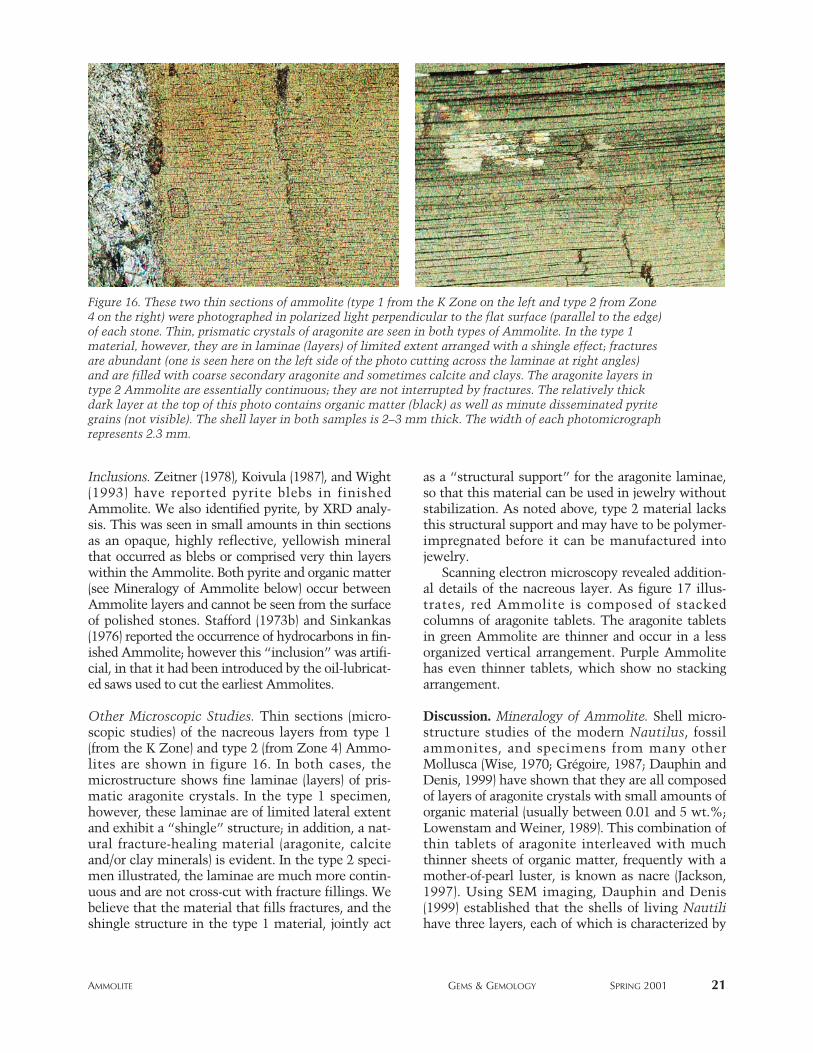
Other Microscopic Studies. Thin sections (micro-scopic studies) of the nacreous layers from type 1(from the K Zone) and type 2 (from Zone 4) Ammo-lites are shown in figure 16. In both cases, themicrostructure shows fine laminae (layers) of pris-matic aragonite crystals. In the type 1 specimen,however, these laminae are of limited lateral extentand exhibit a “shingle” structure; in addition, a nat-ural fracture-healing material (aragonite, calciteand/or clay minerals) is evident. In the type 2 speci-men illustrated, the laminae are much more contin-uous and are not cross-cut with fracture fillings. Webelieve that the material that fills fractures, and theshingle structure in the type 1 material, jointly act
as a “structural support” for the aragonite laminae,so that this material can be used in jewelry withoutstabilization. As noted above, type 2 material lacksthis structural support and may have to be polymer-impregnated before it can be manufactured intojewelry.
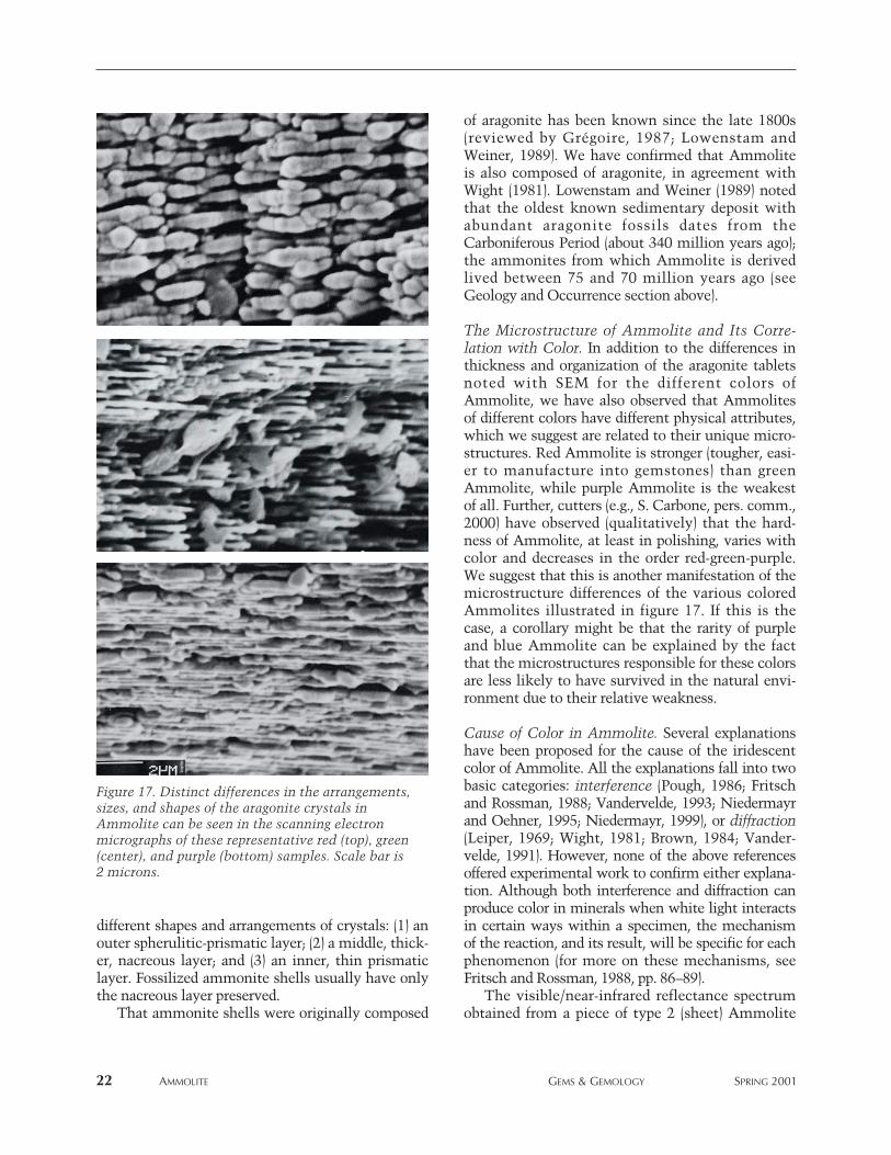
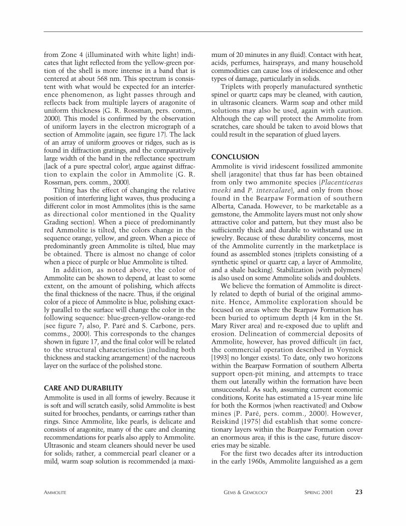
Scanning electron microscopy revealed addition-al details of the nacreous layer. As figure 17 illus-trates, red Ammolite is composed of stackedcolumns of aragonite tablets. The aragonite tabletsin green Ammolite are thinner and occur in a lessorganized vertical arrangement. Purple Ammolitehas even thinner tablets, which show no stackingarrangement.
Discussion. Mineralogy of Ammolite. Shell micro-structure studies of the modern Nautilus, fossilammonites, and specimens from many otherMollusca (Wise, 1970; Grégoire, 1987; Dauphin andDenis, 1999) have shown that they are all composedof layers of aragonite crystals with small amounts oforganic material (usually between 0.01 and 5 wt.%;Lowenstam and Weiner, 1989). This combination ofthin tablets of aragonite interleaved with muchthinner sheets of organic matter, frequently with amother-of-pearl luster, is known as nacre (Jackson,1997). Using SEM imaging, Dauphin and Denis(1999) established that the shells of living Nautilihave three layers, each of which is characterized by
AMMOLITE GEMS & GEMOLOGY SPRING 2001 21
Figure 16. These two thin sections of ammolite (type 1 from the K Zone on the left and type 2 from Zone4 on the right) were photographed in polarized light perpendicular to the flat surface (parallel to the edge)of each stone. Thin, prismatic crystals of aragonite are seen in both types of Ammolite. In the type 1material, however, they are in laminae (layers) of limited extent arranged with a shingle effect; fracturesare abundant (one is seen here on the left side of the photo cutting across the laminae at right angles)and are filled with coarse secondary aragonite and sometimes calcite and clays. The aragonite layers intype 2 Ammolite are essentially continuous; they are not interrupted by fractures. The relatively thickdark layer at the top of this photo contains organic matter (black) as well as minute disseminated pyritegrains (not visible). The shell layer in both samples is 2–3 mm thick. The width of each photomicrographrepresents 2.3 mm.
different shapes and arrangements of crystals: (1) anouter spherulitic-prismatic layer; (2) a middle, thick-er, nacreous layer; and (3) an inner, thin prismaticlayer. Fossilized ammonite shells usually have onlythe nacreous layer preserved.
That ammonite shells were originally composed
of aragonite has been known since the late 1800s(reviewed by Grégoire, 1987; Lowenstam andWeiner, 1989). We have confirmed that Ammoliteis also composed of aragonite, in agreement withWight (1981). Lowenstam and Weiner (1989) notedthat the oldest known sedimentary deposit withabundant aragonite fossils dates from theCarboniferous Period (about 340 million years ago);the ammonites from which Ammolite is derivedlived between 75 and 70 million years ago (seeGeology and Occurrence section above).
The Microstructure of Ammolite and Its Corre-lation with Color. In addition to the differences inthickness and organization of the aragonite tabletsnoted with SEM for the different colors ofAmmolite, we have also observed that Ammolitesof different colors have different physical attributes,which we suggest are related to their unique micro-structures. Red Ammolite is stronger (tougher, easi-er to manufacture into gemstones) than greenAmmolite, while purple Ammolite is the weakestof all. Further, cutters (e.g., S. Carbone, pers. comm.,2000) have observed (qualitatively) that the hard-ness of Ammolite, at least in polishing, varies withcolor and decreases in the order red-green-purple.We suggest that this is another manifestation of themicrostructure differences of the various coloredAmmolites illustrated in figure 17. If this is thecase, a corollary might be that the rarity of purpleand blue Ammolite can be explained by the factthat the microstructures responsible for these colorsare less likely to have survived in the natural envi-ronment due to their relative weakness.
Cause of Color in Ammolite. Several explanationshave been proposed for the cause of the iridescentcolor of Ammolite. All the explanations fall into twobasic categories: interference (Pough, 1986; Fritschand Rossman, 1988; Vandervelde, 1993; Niedermayrand Oehner, 1995; Niedermayr, 1999), or diffraction(Leiper, 1969; Wight, 1981; Brown, 1984; Vander-velde, 1991). However, none of the above referencesoffered experimental work to confirm either explana-tion. Although both interference and diffraction canproduce color in minerals when white light interactsin certain ways within a specimen, the mechanismof the reaction, and its result, will be specific for eachphenomenon (for more on these mechanisms, seeFritsch and Rossman, 1988, pp. 86–89).
The visible/near-infrared reflectance spectrumobtained from a piece of type 2 (sheet) Ammolite
22 AMMOLITE GEMS & GEMOLOGY SPRING 2001
Figure 17. Distinct differences in the arrangements,sizes, and shapes of the aragonite crystals inAmmolite can be seen in the scanning electronmicrographs of these representative red (top), green(center), and purple (bottom) samples. Scale bar is2 microns.
from Zone 4 (illuminated with white light) indi-cates that light reflected from the yellow-green por-tion of the shell is more intense in a band that iscentered at about 568 nm. This spectrum is consis-tent with what would be expected for an interfer-ence phenomenon, as light passes through andreflects back from multiple layers of aragonite ofuniform thickness (G. R. Rossman, pers. comm.,2000). This model is confirmed by the observationof uniform layers in the electron micrograph of asection of Ammolite (again, see figure 17). The lackof an array of uniform grooves or ridges, such as isfound in diffraction gratings, and the comparativelylarge width of the band in the reflectance spectrum(lack of a pure spectral color), argue against diffrac-tion to explain the color in Ammolite (G. R.Rossman, pers. comm., 2000).
Tilting has the effect of changing the relativeposition of interfering light waves, thus producing adifferent color in most Ammolites (this is the sameas directional color mentioned in the QualityGrading section). When a piece of predominantlyred Ammolite is tilted, the colors change in thesequence orange, yellow, and green. When a piece ofpredominantly green Ammolite is tilted, blue maybe obtained. There is almost no change of colorwhen a piece of purple or blue Ammolite is tilted.
In addition, as noted above, the color ofAmmolite can be shown to depend, at least to someextent, on the amount of polishing, which affectsthe final thickness of the nacre. Thus, if the originalcolor of a piece of Ammolite is blue, polishing exact-ly parallel to the surface will change the color in thefollowing sequence: blue-green-yellow-orange-red(see figure 7; also, P. Paré and S. Carbone, pers.comms., 2000). This corresponds to the changesshown in figure 17, and the final color will be relatedto the structural characteristics (including boththickness and stacking arrangement) of the nacreouslayer on the surface of the polished stone.
CARE AND DURABILITYAmmolite is used in all forms of jewelry. Because itis soft and will scratch easily, solid Ammolite is bestsuited for brooches, pendants, or earrings rather thanrings. Since Ammolite, like pearls, is delicate andconsists of aragonite, many of the care and cleaningrecommendations for pearls also apply to Ammolite.Ultrasonic and steam cleaners should never be usedfor solids; rather, a commercial pearl cleaner or amild, warm soap solution is recommended (a maxi-
mum of 20 minutes in any fluid). Contact with heat,acids, perfumes, hairsprays, and many householdcommodities can cause loss of iridescence and othertypes of damage, particularly in solids.
Triplets with properly manufactured syntheticspinel or quartz caps may be cleaned, with caution,in ultrasonic cleaners. Warm soap and other mildsolutions may also be used, again with caution.Although the cap will protect the Ammolite fromscratches, care should be taken to avoid blows thatcould result in the separation of glued layers.
CONCLUSIONAmmolite is vivid iridescent fossilized ammoniteshell (aragonite) that thus far has been obtainedfrom only two ammonite species (Placenticerasmeeki and P. intercalare), and only from thosefound in the Bearpaw Formation of southernAlberta, Canada. However, to be marketable as agemstone, the Ammolite layers must not only showattractive color and pattern, but they must also besufficiently thick and durable to withstand use injewelry. Because of these durability concerns, mostof the Ammolite currently in the marketplace isfound as assembled stones (triplets consisting of asynthetic spinel or quartz cap, a layer of Ammolite,and a shale backing). Stabilization (with polymers)is also used on some Ammolite solids and doublets.
We believe the formation of Ammolite is direct-ly related to depth of burial of the original ammo-nite. Hence, Ammolite exploration should befocused on areas where the Bearpaw Formation hasbeen buried to optimum depth (4 km in the St.Mary River area) and re-exposed due to uplift anderosion. Delineation of commercial deposits ofAmmolite, however, has proved difficult (in fact,the commercial operation described in Voynick[1993] no longer exists). To date, only two horizonswithin the Bearpaw Formation of southern Albertasupport open-pit mining, and attempts to tracethem out laterally within the formation have beenunsuccessful. As such, assuming current economicconditions, Korite has estimated a 15-year mine lifefor both the Kormos (when reactivated) and Oxbowmines (P. Paré, pers. comm., 2000). However,Reiskind (1975) did establish that some concre-tionary layers within the Bearpaw Formation coveran enormous area; if this is the case, future discov-eries may be sizable.
For the first two decades after its introductionin the early 1960s, Ammolite languished as a gem
AMMOLITE GEMS & GEMOLOGY SPRING 2001 23
REFERENCESAmmolite. New gems from old fossils (1984) Southern Jeweler,
Vol. 59, No. 9, pp. 25, 31.Barnson D. (1996) Ammolite. Privately published by Donna L.
Barnson, Selkirk, Manitoba, Canada, 24 pp.Barnson D. (2000) Ammolite 2. A Guide for Gemmologists,
Jewellers and Lapidaries. Privately published by Donna L.Barnson, Selkirk, Manitoba, Canada, 116 pp.
Boyd W.F., Wight W. (1983) Gemstones of Canada. Journal ofGemmology, Vol. 8, No. 6, pp. 544–562.
Brown G. (1984) Korite —A unique organic gem. AustralianGemmologist, Vol. 15, No. 6, pp. 206–208.
Carbone S. (1991) Composite Gem Stone and ProductionMethod. Canadian Patent 1281871, issued March 26, 1991;U.S. Patent 5,015,499, issued May 14, 1991.
Crowningshield R. (1977) A new jewelry item. Gems & Gemol-ogy, Vol. 15, No. 10, p. 312.
Dauphin Y., Denis A. (1999) Diagenèse compareé des phasesminérales et organiques solubles dans les tests aragonitiquesde nautiles et d’ammonites. Bulletin de la Société Géologiquede France, Vol. 170, No. 3, pp. 355–365.
Dick G. (1991) Short in supply, long in beauty. American JewelryManufacturer, Vol. 39, No. 7, pp. 34–35.
Dowling D.B. (1917) The Southern Plains of Alberta. GeologicalSurvey of Canada, Memoir 93.
England T.D.J., Bustin R.M. (1986) Thermal maturation of theWestern Canadian Sedimentary Basin south of the Red DeerRiver: I) Alberta Plains. Bulletin of Canadian PetroleumGeology, Vol. 34, No. 1, pp. 71–90.
Fritsch E., Rossman G.R. (1988) An update on color in gems, Part3: Colors caused by band gaps and physical phenomena.Gems & Gemology, Vol. 24, No. 2, pp. 81–102.
Gem Reference Guide (1995) Gemological Institute of America,Santa Monica, CA, 270 pp.
Gemstone unique to Canada making waves (1999) JewelleryNews Asia, No. 176, pp. 62, 64.
Grégoire C. (1987) Ultrastructure of the Nautilus shell. In W.B.Saunders and N.H. Landman, Eds., Nautilus—The Biology
and Paleobiology of a Living Fossil. Plenum Press, New York,pp. 463–486.
Gübelin E. (1980) Ammolith. Ein neuer fossiler Schmuckstein.Lapis, Vol. 5, No. 4, pp. 19–24 (in German).
Hadley W.D. (1981a) “Korite”—Here are more details of this amaz-ing “new” gemstone. Rock & Gem, Vol. 11, No. 4, pp. 60–61.
Hadley W.D. (1981b) “Korite”—A new gemstone that’s 70 mil-lion years old. Rock & Gem, Vol. 11, No. 3, pp. 44–46.
Hatcher J.B., Stanton T.W. (1903) The stratigraphic position ofthe Judith River beds and their correlation with Belly Riverbeds. Science, Vol. 18, No. 5, pp. 211–212.
Hembroff W.V. (1998) Action No. 9806-00404, Court of Queen’sBench of Alberta, Judicial District of Lethbridge/Macleod,July 16.
Jackson J.A. (1997) Glossary of Geology, 4th ed. AmericanGeological Institute, Alexandria, VA, 769 pp.
Jarand W.H. (1982) Processing ammonite shell. Lapidary Journal,Vol. 36, No. 5, p. 948.
Johnson M.L., Koivula J.I., McClure S.F., DeGhionno D., Eds.(2000) Gem news: Mosaic ammonite. Gems & Gemology,Vol. 36, No. 3, pp. 261–262.
Koivula J.I. (1987) Pyrite in Canadian ammonite. AustralianGemmologist, Vol. 16, No. 8, pp. 304–307.
Koivula J.I., Kammerling R.C. (1991) Plastic-treated Ammolite.Gems & Gemology, Vol. 27, No. 1, p. 52.
Kraus P.D. (1982) Korite from Alberta, Canada. Lapidary Journal,Vol. 35, No. 10, pp. 1994, 1996.
Leiper H. (1969) A new fossil gem is found in Alberta, Canada.Lapidary Journal, Vol. 23, No. 7, pp. 932, 937. Reprinted inLapidary Journal, Vol. 51, No. 4, 1997, p. 39.
Link T.A., Childerhose A.J. (1931) Bearpaw shale and contiguousformations in Lethbridge area, Alberta. Bulletin of theAmerican Association of Petroleum Geologists, Vol. 15, Part2, pp. 1227–1242.
Lowenstam H.A., Weiner S. (1989) On Biomineralization. OxfordUniversity Press, Oxford, 324 pp.
Mossop G.D., Shetsen I., compilers (1994) Geological Atlas of theWestern Canada Sedimentary Basin. Published jointly by theCanadian Society of Petroleum Geologists and Alberta
material primarily because of the limited supplyof durable rough, the lack of uniform marketing(e.g., a multitude of trade names), and the incon-sistent quality of the assembled stones. In the pasttwo decades, as a result of the development ofnew mines and improved manufacturing tech-
niques for assembled stones and stabilizing mate-rial that delaminated, Ammolite has gained recog-nition worldwide. With a steady future supply,and wide versatility in today’s jewelry designs, weare confident that Ammolite will continue togrow in popularity.
24 AMMOLITE GEMS & GEMOLOGY SPRING 2001
ABOUT THE AUTHORS
Mr. Mychaluk is a professional geologist in Calgary, Alberta,Canada. Dr. Levinson ([email protected]) and Dr.Hall are professor emeritus and associate professor, respec-tively, in the Department of Geology and Geophysics,University of Calgary.
Acknowledgments: The authors thank Pierre Paré, presidentof Korite International Ltd., Calgary, Alberta, for supplyingresearch specimens, unpublished data, permission to visit theKorite manufacturing facilities in Calgary, and access to the
Kormos and Oxbow Ammolite mines near Lethbridge. SantoCarbone of Calgary kindly reviewed this article and providedunpublished data and samples. Professor G. R. Rossman ofthe California Institute of Technology kindly supplied thereflectance spectrum and discussed with us the origin of colorin Ammolite. D. Glatiotis and M. Glatiotis, Department ofGeology and Geophysics, University of Calgary, are thankedfor taking scanning electron micrographs and for X-ray diffrac-tion patterns. Thanks also to Barnson Photography of Selkirk,Manitoba, and Aurora Canadian Jewellery of Calgary for pro-viding photographs. Discussions with Allan Ingelson of Calgaryand Paul Evanson of Edmonton were very informative.
Gems & Gemology requires that all articles undergo a peer review process in whicheach manuscript is reviewed by at least three experts in the field. This process is vital tothe accuracy and readability of the published article, but it is also time-consuming forthe reviewer. Because members of our Editorial Review Board cannot have expertise inevery area, we sometimes call on others in our community to share their intellect andinsight. In addition to the members of our Editorial Review Board, we extend a heartfeltthanks to the following individuals who reviewed manuscripts for G&G in 2000:
Research Council, Calgary, Alberta, 510 pp. Niedermayr G. (1994) The Bleiberg box. Lapidary Journal, Vol.
48, No. 6, pp. 37–40, 42. Niedermayr G. (1999) Der Schmuckstein aus der Schale.
Ammolite. In R. Bode, J. Keilmann, W. Lieber, and G.Schairer, Eds., Von Ammoniten und Zwillingen, Mineralien-tage München Messethemenheft ’99 Aussstellerverzeichnis,pp. 162–168.
Niedermayr G., Oehner K. (1995) Ammolite, ein organischerSchmuckstein aus Alberta, Kanada. Mineralien-Welt, Vol. 6,No. 6, pp. 41–46.
Organic Alberta gemstone posed numerous mining problems(1985) Canadian Mining Journal, Vol. 106, No. 4, p. 11.
Pough F.H. (1986) Ammolite—Grandmother-of-pearl. LapidaryJournal, Vol. 39, No. 10, pp. 35–41.
Reiskind J. (1975) Marine concretionary faunas of the uppermostBearpaw Shale (Maestrichtian) in eastern Montana andsouthwestern Saskatchewan. In W.G.E. Caldwell, Ed., TheCretaceous System in the Western Interior of NorthAmerica, Geological Association of Canada Special PaperNo. 13, pp. 235–252.
Sinkankas J. (1976) Gemstones of North America, Vol. II. VanNostrand Reinhold, New York, 494 pp.
Sinkankas J. (1997) Gemstones of North America, Vol. III.Geoscience Press, Tucson, AZ, 527 pp.
Stafford P. (1973a) Ammonites and baculites in southern Alberta(part 1). Gems and Minerals, No. 424, pp. 32–34.
Stafford P. (1973b) Ammonites and baculites in southern Alberta(part 2). Gems and Minerals, No. 425, pp. 27, 42–44.
Stafford P. (1973c) Ammonites and baculites in southern Alberta(part 3). Gems and Minerals, No. 426, pp. 30, 31, 41–43.
Tsujita C.J., Westermann G.E.G. (1998) Ammonoid habitats andhabits in the Western Interior Seaway: A case study from theUpper Cretaceous Bearpaw Formation of southern Alberta,Canada. Palaeogeography, Palaeoclimatology, Palaeoecology,Vol. 144, Nos. 1–2, pp. 135–160.
Vandervelde R. (1991) Ammolite, an organic gemstone fromAlberta. In Z.D. Hora, W.N. Hamilton, B. Grant, and P.D.Kelly, Eds., Industrial Minerals of Alberta and BritishColumbia, Canada, British Columbia Geological Survey,Open File 1991-23; and Alberta Geological Survey Infor-mation Series 115, pp. 171–172.
Vandervelde R. (1993) Ammolite, an organic gemstone fromAlberta. Canadian Gemmologist, Vol. 14, No. 2, pp. 53–57.
Voynick S. (1993) Gem ammonite comes of age. Rock & Gem,Vol. 23, No. 3, pp. 50, 53–54.
Ward G., Vandervelde R., Paré P. (1982) Macro-Paleo BearpawFormation, Southern Alberta. Trip No. 11, Field Trip Guide-book, Canadian Society of Petroleum Geologists.
Wight Q. (1993) Canadian Ammolite—The high, dry sea flooryields opal-like material. Rock & Gem, Vol. 23, No. 12, pp.42, 43, 45–47.
Wight W. (1981) “Korite”—Fossil ammonite shell from Alberta,Canada. Journal of Gemmology, Vol. 17, No. 6, pp. 406–415.
Wight W. (1995) Canadian gemstones: Old & new. CanadianGemmologist, Vol. 16, No. 3, pp. 82–87.
Wise S.W. (1970) Microarchitecture and mode of formation ofnacre (mother-of-pearl) in pelecypods, gastropods, andcephalopods. Eclogae Geologicae Helvetiae, Vol. 63, No. 3,pp. 775–797.
Zeitner J.C. (1978) Calcentine is Ammolite is nacre. LapidaryJournal, Vol. 32, No. 2, pp. 622–628.
AMMOLITE GEMS & GEMOLOGY SPRING 2001 25
2000 MANUSCRIPT REVIEWERS
Ms. Dona DirlamMs. Cindy EdelsteinMr. Israel EliezriMr. Doug FiskeDr. Edward J. GübelinMs. Gina Latendresse
Dr. G. NiedermayrDr. John SaulMs. Hedda SchupakDr. Lin G. SutherlandMr. Ron VanderlindenDr. Christopher Welbourn
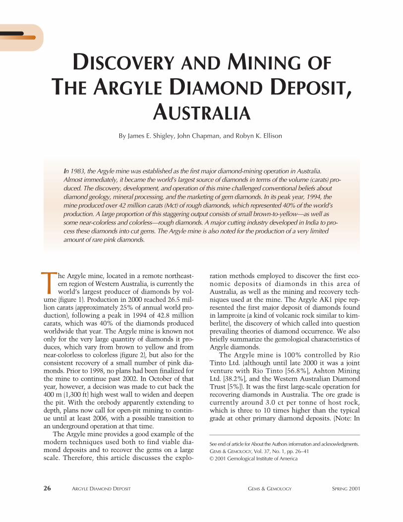
26 ARGYLE DIAMOND DEPOSIT GEMS & GEMOLOGY SPRING 2001
ration methods employed to discover the first eco-nomic deposits of diamonds in this area ofAustralia, as well as the mining and recovery tech-niques used at the mine. The Argyle AK1 pipe rep-resented the first major deposit of diamonds foundin lamproite (a kind of volcanic rock similar to kim-berlite), the discovery of which called into questionprevailing theories of diamond occurrence. We alsobriefly summarize the gemological characteristics ofArgyle diamonds.
The Argyle mine is 100% controlled by RioTinto Ltd. (although until late 2000 it was a jointventure with Rio Tinto [56.8%], Ashton MiningLtd. [38.2%], and the Western Australian DiamondTrust [5%]). It was the first large-scale operation forrecovering diamonds in Australia. The ore grade iscurrently around 3.0 ct per tonne of host rock,which is three to 10 times higher than the typicalgrade at other primary diamond deposits. (Note: In
By James E. Shigley, John Chapman, and Robyn K. Ellison
DISCOVERY AND MINING OFTHE ARGYLE DIAMOND DEPOSIT,
AUSTRALIA
See end of article for About the Authors information and acknowledgments.GEMS & GEMOLOGY, Vol. 37, No. 1, pp. 26–41© 2001 Gemological Institute of America
IIn 1983, the Argyle mine was established as the first major diamond-mining operation in Australia.Almost immediately, it became the world’s largest source of diamonds in terms of the volume (carats) pro-duced. The discovery, development, and operation of this mine challenged conventional beliefs aboutdiamond geology, mineral processing, and the marketing of gem diamonds. In its peak year, 1994, themine produced over 42 million carats (Mct) of rough diamonds, which represented 40% of the world’sproduction. A large proportion of this staggering output consists of small brown-to-yellow—as well assome near-colorless and colorless—rough diamonds. A major cutting industry developed in India to pro-cess these diamonds into cut gems. The Argyle mine is also noted for the production of a very limitedamount of rare pink diamonds.
he Argyle mine, located in a remote northeast-ern region of Western Australia, is currently theworld’s largest producer of diamonds by vol-
ume (figure 1). Production in 2000 reached 26.5 mil-lion carats (approximately 25% of annual world pro-duction), following a peak in 1994 of 42.8 millioncarats, which was 40% of the diamonds producedworldwide that year. The Argyle mine is known notonly for the very large quantity of diamonds it pro-duces, which vary from brown to yellow and fromnear-colorless to colorless (figure 2), but also for theconsistent recovery of a small number of pink dia-monds. Prior to 1998, no plans had been finalized forthe mine to continue past 2002. In October of thatyear, however, a decision was made to cut back the400 m (1,300 ft) high west wall to widen and deepenthe pit. With the orebody apparently extending todepth, plans now call for open-pit mining to contin-ue until at least 2006, with a possible transition toan underground operation at that time.
The Argyle mine provides a good example of themodern techniques used both to find viable dia-mond deposits and to recover the gems on a largescale. Therefore, this article discusses the explo-
T
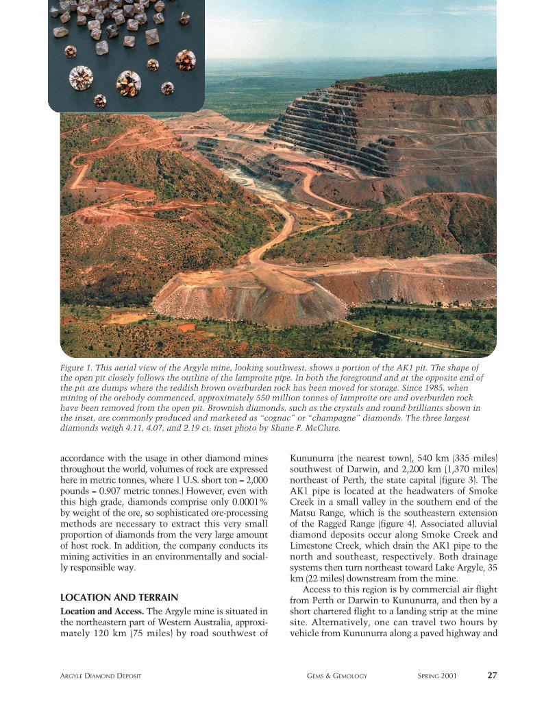
ARGYLE DIAMOND DEPOSIT GEMS & GEMOLOGY SPRING 2001 27
accordance with the usage in other diamond minesthroughout the world, volumes of rock are expressedhere in metric tonnes, where 1 U.S. short ton = 2,000pounds = 0.907 metric tonnes.) However, even withthis high grade, diamonds comprise only 0.0001%by weight of the ore, so sophisticated ore-processingmethods are necessary to extract this very smallproportion of diamonds from the very large amountof host rock. In addition, the company conducts itsmining activities in an environmentally and social-ly responsible way.
LOCATION AND TERRAINLocation and Access. The Argyle mine is situated inthe northeastern part of Western Australia, approxi-mately 120 km (75 miles) by road southwest of
Kununurra (the nearest town), 540 km (335 miles)southwest of Darwin, and 2,200 km (1,370 miles)northeast of Perth, the state capital (figure 3). TheAK1 pipe is located at the headwaters of SmokeCreek in a small valley in the southern end of theMatsu Range, which is the southeastern extensionof the Ragged Range (figure 4). Associated alluvialdiamond deposits occur along Smoke Creek andLimestone Creek, which drain the AK1 pipe to thenorth and southeast, respectively. Both drainagesystems then turn northeast toward Lake Argyle, 35km (22 miles) downstream from the mine.
Access to this region is by commercial air flightfrom Perth or Darwin to Kununurra, and then by ashort chartered flight to a landing strip at the minesite. Alternatively, one can travel two hours byvehicle from Kununurra along a paved highway and
Figure 1. This aerial view of the Argyle mine, looking southwest, shows a portion of the AK1 pit. The shape ofthe open pit closely follows the outline of the lamproite pipe. In both the foreground and at the opposite end ofthe pit are dumps where the reddish brown overburden rock has been moved for storage. Since 1985, whenmining of the orebody commenced, approximately 550 million tonnes of lamproite ore and overburden rockhave been removed from the open pit. Brownish diamonds, such as the crystals and round brilliants shown inthe inset, are commonly produced and marketed as “cognac” or “champagne” diamonds. The three largestdiamonds weigh 4.11, 4.07, and 2.19 ct; inset photo by Shane F. McClure.
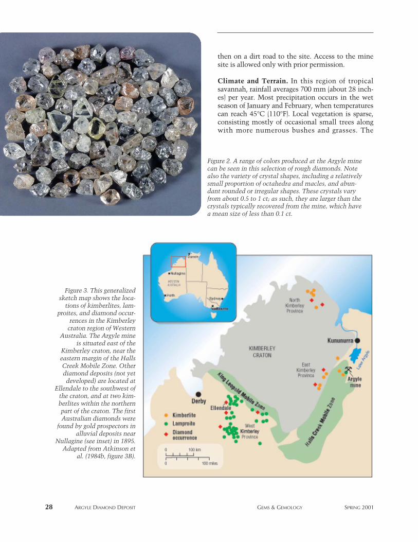
then on a dirt road to the site. Access to the minesite is allowed only with prior permission.
Climate and Terrain. In this region of tropicalsavannah, rainfall averages 700 mm (about 28 inch-es) per year. Most precipitation occurs in the wetseason of January and February, when temperaturescan reach 45°C (110°F). Local vegetation is sparse,consisting mostly of occasional small trees alongwith more numerous bushes and grasses. The
28 ARGYLE DIAMOND DEPOSIT GEMS & GEMOLOGY SPRING 2001
Figure 2. A range of colors produced at the Argyle minecan be seen in this selection of rough diamonds. Notealso the variety of crystal shapes, including a relativelysmall proportion of octahedra and macles, and abun-dant rounded or irregular shapes. These crystals varyfrom about 0.5 to 1 ct; as such, they are larger than thecrystals typically recovered from the mine, which havea mean size of less than 0.1 ct.
Figure 3. This generalizedsketch map shows the loca-
tions of kimberlites, lam-proites, and diamond occur-
rences in the Kimberleycraton region of Western
Australia. The Argyle mineis situated east of the
Kimberley craton, near theeastern margin of the HallsCreek Mobile Zone. Otherdiamond deposits (not yetdeveloped) are located at
Ellendale to the southwest ofthe craton, and at two kim-berlites within the northernpart of the craton. The firstAustralian diamonds were
found by gold prospectors inalluvial deposits near
Nullagine (see inset) in 1895.Adapted from Atkinson et
al. (1984b, figure 3B).
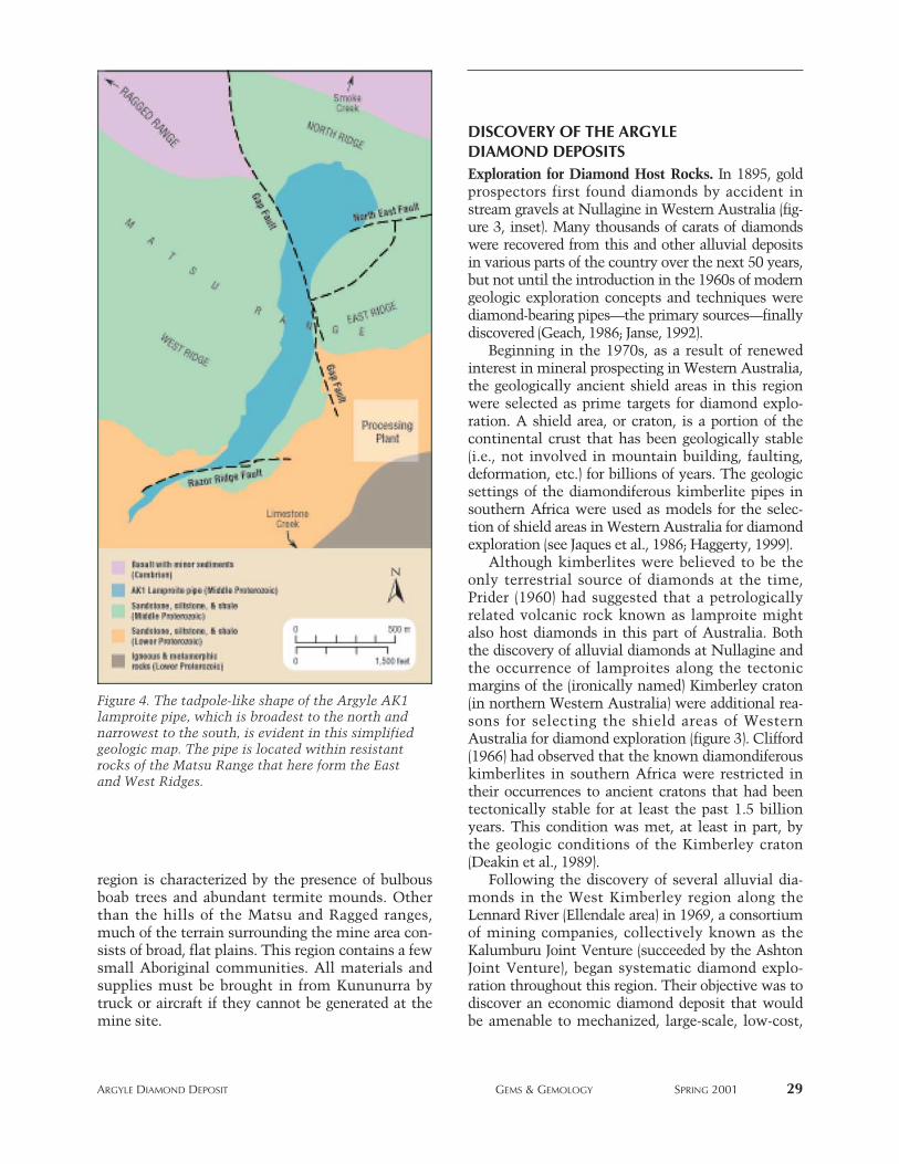
region is characterized by the presence of bulbousboab trees and abundant termite mounds. Otherthan the hills of the Matsu and Ragged ranges,much of the terrain surrounding the mine area con-sists of broad, flat plains. This region contains a fewsmall Aboriginal communities. All materials andsupplies must be brought in from Kununurra bytruck or aircraft if they cannot be generated at themine site.
DISCOVERY OF THE ARGYLEDIAMOND DEPOSITSExploration for Diamond Host Rocks. In 1895, goldprospectors first found diamonds by accident instream gravels at Nullagine in Western Australia (fig-ure 3, inset). Many thousands of carats of diamondswere recovered from this and other alluvial depositsin various parts of the country over the next 50 years,but not until the introduction in the 1960s of moderngeologic exploration concepts and techniques werediamond-bearing pipes—the primary sources––finallydiscovered (Geach, 1986; Janse, 1992).
Beginning in the 1970s, as a result of renewedinterest in mineral prospecting in Western Australia,the geologically ancient shield areas in this regionwere selected as prime targets for diamond explo-ration. A shield area, or craton, is a portion of thecontinental crust that has been geologically stable(i.e., not involved in mountain building, faulting,deformation, etc.) for billions of years. The geologicsettings of the diamondiferous kimberlite pipes insouthern Africa were used as models for the selec-tion of shield areas in Western Australia for diamondexploration (see Jaques et al., 1986; Haggerty, 1999).
Although kimberlites were believed to be theonly terrestrial source of diamonds at the time,Prider (1960) had suggested that a petrologicallyrelated volcanic rock known as lamproite mightalso host diamonds in this part of Australia. Boththe discovery of alluvial diamonds at Nullagine andthe occurrence of lamproites along the tectonicmargins of the (ironically named) Kimberley craton(in northern Western Australia) were additional rea-sons for selecting the shield areas of WesternAustralia for diamond exploration (figure 3). Clifford(1966) had observed that the known diamondiferouskimberlites in southern Africa were restricted intheir occurrences to ancient cratons that had beentectonically stable for at least the past 1.5 billionyears. This condition was met, at least in part, bythe geologic conditions of the Kimberley craton(Deakin et al., 1989).
Following the discovery of several alluvial dia-monds in the West Kimberley region along theLennard River (Ellendale area) in 1969, a consortiumof mining companies, collectively known as theKalumburu Joint Venture (succeeded by the AshtonJoint Venture), began systematic diamond explo-ration throughout this region. Their objective was todiscover an economic diamond deposit that wouldbe amenable to mechanized, large-scale, low-cost,
ARGYLE DIAMOND DEPOSIT GEMS & GEMOLOGY SPRING 2001 29
Figure 4. The tadpole-like shape of the Argyle AK1lamproite pipe, which is broadest to the north andnarrowest to the south, is evident in this simplifiedgeologic map. The pipe is located within resistantrocks of the Matsu Range that here form the Eastand West Ridges.
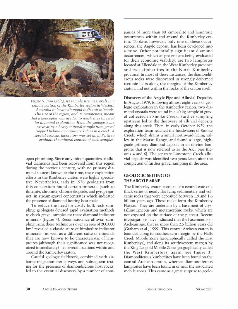
open-pit mining. Since only minor quantities of allu-vial diamonds had been recovered from this regionduring the previous century, with no primary dia-mond sources known at the time, these explorationefforts in the Kimberley craton were highly specula-tive. Nevertheless, early in 1976, geologists fromthis consortium found certain minerals (such asilmenite, chromite, chrome diopside, and pyrope gar-net) in stream-gravel concentrates which indicatedthe presence of diamond-bearing host rocks.
To reduce the need for costly bulk-rock sam-pling, geologists devised rapid evaluation methodsto check gravel samples for these diamond indicatorminerals (figure 5). Reconnaissance alluvial sam-pling using these techniques over an area of 200,000km2 revealed a classic suite of kimberlite indicatorminerals—as well as a different suite of mineralsthat are now known to be characteristic of lam-proites (although their significance was not recog-nized immediately)—at several locations within andaround the Kimberley craton.
Careful geologic fieldwork, combined with air-borne magnetometer surveys and subsequent test-ing for the presence of diamondiferous host rocks,led to the eventual discovery by a number of com-
panies of more than 80 kimberlite and lamproiteoccurrences within and around the Kimberley cra-ton. To date, however, only one of these occur-rences, the Argyle deposit, has been developed intoa mine. Other potentially significant diamondoccurrences, which at present are being evaluatedfor their economic viability, are two lamproiteslocated at Ellendale in the West Kimberley provinceand two kimberlites in the North Kimberleyprovince. In most of these instances, the diamondif-erous rocks were discovered in strongly deformedtectonic belts along the margins of the Kimberleycraton, and not within the rocks of the craton itself.
Discovery of the Argyle Pipe and Alluvial Deposits.In August 1979, following almost eight years of geo-logic exploration in the Kimberley region, two dia-mond crystals were found in a 40 kg sample of grav-el collected in Smoke Creek. Further samplingupstream led to the discovery of alluvial depositsalong this creek. Then, in early October 1979, theexploration team reached the headwaters of SmokeCreek, which drains a small northward-facing val-ley in the Matsu Range, and found a large, high-grade primary diamond deposit in an olivine lam-proite that is now referred to as the AK1 pipe (fig-ures 4 and 6). The separate Limestone Creek allu-vial deposit was identified two years later, after thecompletion of further gravel sampling in the area.
GEOLOGIC SETTING OFTHE ARGYLE MINEThe Kimberley craton consists of a central core of athick series of nearly flat-lying sedimentary and vol-canic rocks that were deposited between 1.9 and 1.6billion years ago. These rocks form the KimberleyPlateau. They are underlain by a basement of crys-talline igneous and metamorphic rocks, which arenot exposed on the surface of the plateau. Recentinvestigations have indicated that the basement is ofArchean age, that is, more than 2.5 billion years old(Graham et al., 1999). This central Archean craton isbounded along its southeastern margin by the HallsCreek Mobile Zone (geographically called the EastKimberleys), and along its southwestern margin bythe King Leopold Mobile Zone (geographically calledthe West Kimberleys; again, see figure 3).Diamondiferous kimberlites have been found on thecentral Archean craton, whereas diamondiferouslamproites have been found in or near the associatedmobile zones. This came as a great surprise to geolo-
30 ARGYLE DIAMOND DEPOSIT GEMS & GEMOLOGY SPRING 2001
Figure 5. Two geologists sample stream gravels in aremote portion of the Kimberley region in Western
Australia to locate diamond indicator minerals.The size of the region, and its remoteness, meant
that a helicopter was needed to reach sites targetedfor diamond exploration. Here, the geologists are
excavating a heavy-mineral sample from graveltrapped behind a natural rock dam in a creek. Aspecial geologic laboratory was set up in Perth to
evaluate the mineral content of such samples.
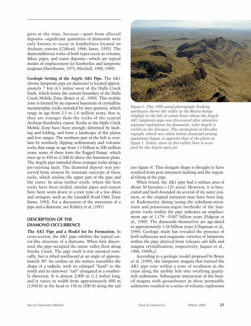
gists at the time, because—apart from alluvialdeposits—significant quantities of diamonds wereonly known to occur in kimberlites located onArchean cratons (Clifford, 1966; Janse, 1992). Thediamondiferous rocks of both types occur as volcanicdikes, pipes, and crater deposits—which are typicalmodes of emplacement for kimberlite and lamproitemagmas (Hawthorne, 1975; Mitchell, 1986, 1989).
Geologic Setting of the Argyle AK1 Pipe. The AK1olivine lamproite pipe (or diatreme) is located approx-imately 7 km (4.5 miles) west of the Halls CreekFault, which forms the eastern boundary of the HallsCreek Mobile Zone (Boxer et al., 1989). This mobilezone is formed by an exposed basement of crystallinemetamorphic rocks intruded by later granites, whichrange in age from 2.5 to 1.8 million years; that is,they are younger than the rocks of the centralArchean Kimberley craton. Rocks in the Halls CreekMobile Zone have been strongly deformed by fault-ing and folding, and form a landscape of flat plainsand low ranges. The northern part of the belt is over-lain by northerly dipping sedimentary and volcanicrocks that range in age from 1.5 billion to 500 millionyears; some of these form the Ragged Range, whichrises up to 450 m (1,500 ft) above the basement plain.The Argyle pipe intruded these younger rocks along apre-existing fault. The diamond deposit was pre-served from erosion by resistant outcrops of theserocks, which enclose the upper part of the pipe andthe crater. In areas further south, where the hostrocks have been eroded, similar pipes and cratershave been worn down to a root zone of a few dikesand stringers, such as the Lissadell Road Dike Zone(Janse, 1992). For a discussion of the structures of apipe and a diatreme, see Kirkley et al. (1991).
DESCRIPTION OF THE DIAMOND OCCURRENCEThe AK1 Pipe and a Model for Its Formation. Incross-section, the AK1 pipe exhibits the typical car-rot-like structure of a diatreme. When first discov-ered, the pipe occupied the entire valley floor alongSmoke Creek. The pipe itself is not oriented verti-cally, but is tilted northward at an angle of approxi-mately 30°. Its outline on the surface resembles theshape of a tadpole, with its enlarged “head” to thenorth and its narrower “tail” elongated in a souther-ly direction. It is almost 2,000 m (1.2 miles) long,and it varies in width from approximately 600 m(1,950 ft) at the head to 150 m (500 ft) along the tail
(see figure 4). This elongate shape is thought to haveresulted from post-intrusion faulting and the region-al tilting of the pipe.
When found, the AK1 pipe had a surface area ofabout 50 hectares (~125 acres). However, it is brec-ciated and fault-bounded on several of its outer con-tacts, so the original intrusion may have been larg-er. Radiometric dating (using the rubidium-stron-tium and potassium-argon methods) of the lam-proite rocks within the pipe indicates an emplace-ment age of 1.178 –0.047 billion years (Pidgeon etal., 1989). The diamonds themselves are age-datedat approximately 1.58 billion years (Chapman et al.,1996). Geologic study has revealed the presence ofboth tuffaceous and magmatic varieties of lamproitewithin the pipe (derived from volcanic ash falls andmagma crystallization, respectively; Jaques et al.,1986, 1989b,c).
According to a geologic model proposed by Boxeret al. (1989), the lamproite magma that formed theAK1 pipe rose within a zone of weakness in thecrust along the mobile belt into overlying quartz-rich sediments. Subsequent interaction of the heat-ed magma with groundwater in these permeablesediments resulted in a series of volcanic explosions
ARGYLE DIAMOND DEPOSIT GEMS & GEMOLOGY SPRING 2001 31
Figure 6. This 1983 aerial photograph (lookingnortheast) shows the valley in the Matsu Range(slightly to the left of center here) where the ArgyleAK1 lamproite pipe was discovered after extensiveregional exploration for diamonds. Lake Argyle isvisible in the distance. The orientation of this pho-tograph, which was taken before diamond-miningoperations began, is opposite that of the photo infigure 1. Today, most of this valley floor is occu-pied by the Argyle open pit.
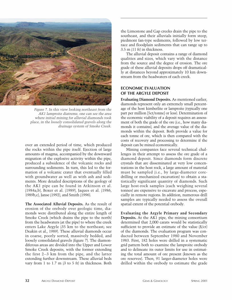
over an extended period of time, which producedthe rocks within the pipe itself. Ejection of largeamounts of magma, accompanied by the downwardmigration of the explosive activity within the pipe,produced a subsidence of the volcanic rocks andsurrounding sediments. In turn, this led to the for-mation of a volcanic crater that eventually filledwith groundwater as well as with ash and sedi-ments. More detailed descriptions of the geology ofthe AK1 pipe can be found in Atkinson et al.(1984a,b), Boxer et al. (1989), Jaques et al. (1986,1989b,c), Janse (1992), and Smith (1996).
The Associated Alluvial Deposits. As the result oferosion of the orebody over geologic time, dia-monds were distributed along the entire length ofSmoke Creek (which drains the pipe to the north)from the headwaters (at the pipe) to where the creekenters Lake Argyle (35 km to the northeast; seeDeakin et al., 1989). These alluvial diamonds occurin coarse, poorly sorted, massively bedded, andloosely consolidated gravels (figure 7). The diamon-diferous areas are divided into the Upper and LowerSmoke Creek deposits, with the former extendingthe first 2–3 km from the pipe, and the latterextending further downstream. These alluvial bedsvary from 1 to 1.7 m (3 to 5 ft) in thickness. Both
the Limestone and Gap creeks drain the pipe to thesoutheast, and their alluvials initially form steep,piedmont fan-type sediments, followed by low ter-race and floodplain sediments that can range up to3.5 m (11 ft) in thickness.
The alluvial deposit contains a range of diamondqualities and sizes, which vary with the distancefrom the source and the degree of erosion. The oregrade of these alluvial deposits drops off dramatical-ly at distances beyond approximately 10 km down-stream from the headwaters of each creek.
ECONOMIC EVALUATION OF THE ARGYLE DEPOSITEvaluating Diamond Deposits. As mentioned earlier,diamonds represent only an extremely small percent-age of the host kimberlite or lamproite (typically onepart per million [5ct/tonne] or less). Determination ofthe economic viability of a deposit requires an assess-ment of both the grade of the ore (i.e., how many dia-monds it contains), and the average value of the dia-monds within the deposit. Both provide a value foreach tonne of ore, which is then compared with thecosts of recovery and processing to determine if thedeposit can be mined economically.
Mining companies face several technical chal-lenges in their attempt to assess the ore grade of adiamond deposit. Since diamonds form discretecrystals that are disseminated at very low concen-trations in the host rock, a large amount of materialmust be sampled (i.e., by large-diameter core-drilling or mechanized excavation) to obtain a sta-tistically significant quantity of diamonds. Suchlarge host-rock samples (each weighing severaltonnes) are expensive to excavate and process, espe-cially in remote regions. In addition, numerous drillsamples are typically needed to assess the overallspatial extent of the potential orebody.
Evaluating the Argyle Primary and SecondaryDeposits. At the AK1 pipe, the mining consortiumdetermined that 2,000 carats would be statisticallysufficient to provide an estimate of the value ($/ct)of the diamonds. The evaluation program was con-ducted between September 1980 and November1983. First, 182 holes were drilled in a systematicgrid pattern both to examine the lamproite orebodyand to delineate its outer limits for use in estimat-ing the total amount of ore present (known as theore reserves). Then, 91 larger-diameter holes weredrilled within the orebody to estimate the grade
32 ARGYLE DIAMOND DEPOSIT GEMS & GEMOLOGY SPRING 2001
Figure 7. In this view looking northeast from theAK1 lamproite diatreme, one can see the area
where initial mining for alluvial diamonds tookplace, in the loosely consolidated gravels along the
drainage system of Smoke Creek.
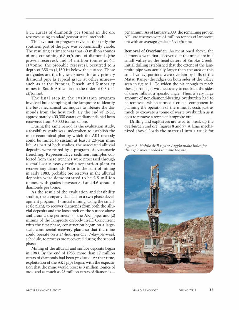
(i.e., carats of diamonds per tonne) in the orereserves using standard geostatistical methods.
This evaluation program revealed that only thesouthern part of the pipe was economically viable.The resulting estimate was that 60 million tonnesof ore, containing 6.8 ct/tonne of diamonds (theproven reserves), and 14 million tonnes at 6.1ct/tonne (the probable reserves), occurred to adepth of 350 m (1,150 ft) below the surface. Theseore grades are the highest known for any primarydiamond pipe (a typical grade at other mines—such as at the Premier, Finsch, and Kimberleymines in South Africa—is on the order of 0.5 to 1ct/tonne).
The final step in the evaluation programinvolved bulk sampling of the lamproite to identifythe best mechanical techniques to liberate the dia-monds from the host rock. By the end of 1982,approximately 400,000 carats of diamonds had beenrecovered from 60,000 tonnes of ore.
During the same period as the evaluation study,a feasibility study was undertaken to establish themost economical plan by which the AK1 orebodycould be mined to sustain at least a 20-year minelife. As part of both studies, the associated alluvialdeposits were tested by a program of systematictrenching. Representative sediment samples col-lected from these trenches were processed througha small-scale heavy-media separation plant torecover any diamonds. Prior to the start of miningin early 1983, probable ore reserves in the alluvialdeposits were demonstrated to be 2.5 milliontonnes, with grades between 3.0 and 4.6 carats ofdiamonds per tonne.
As the result of the evaluation and feasibilitystudies, the company decided on a two-phase devel-opment program: (1) initial mining, using the small-scale plant, to recover diamonds from both the allu-vial deposits and the loose rock on the surface aboveand around the perimeter of the AK1 pipe; and (2)mining of the lamproite orebody itself. Concurrentwith the first phase, construction began on a large-scale commercial recovery plant, so that the minecould operate on a 24-hour-per-day, 7-day-per-weekschedule, to process ore recovered during the secondphase.
Mining of the alluvial and surface deposits beganin 1983. By the end of 1985, more than 17 millioncarats of diamonds had been produced. At that time,exploitation of the AK1 pipe began, with the expecta-tion that the mine would process 3 million tonnes ofore—and as much as 25 million carats of diamonds—
per annum. As of January 2000, the remaining provenAK1 ore reserves were 61 million tonnes of lamproiteore with an average grade of 2.9 ct/tonne.
Removal of Overburden. As mentioned above, thediamonds were first discovered at the mine site in asmall valley at the headwaters of Smoke Creek.Initial drilling established that the extent of the lam-proite pipe was actually larger than the area of thissmall valley; portions were overlain by hills of theMatsu Range (the ridges on both sides of the valleyseen in figure 1). To widen the pit enough to reachthese portions, it was necessary to cut back the sidesof these hills at a specific angle. Thus, a very largeamount of non-diamond-bearing overburden had tobe removed, which formed a crucial component inplanning the operation of the mine. It costs just asmuch to excavate a tonne of waste overburden as itdoes to remove a tonne of lamproite ore.
Drilling and explosives are used to break up theoverburden and ore (figures 8 and 9). A large mecha-nized shovel loads the material into a truck for
ARGYLE DIAMOND DEPOSIT GEMS & GEMOLOGY SPRING 2001 33
Figure 8. Mobile drill rigs at Argyle make holes forthe explosives needed to mine the ore.
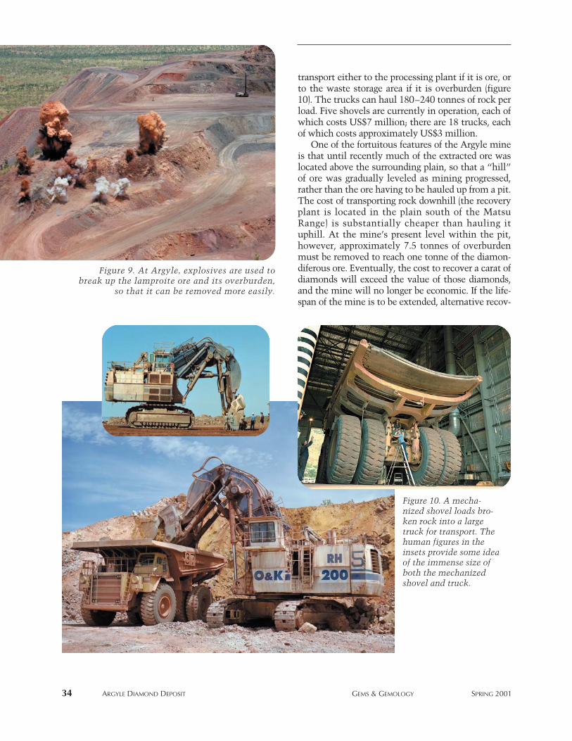
transport either to the processing plant if it is ore, orto the waste storage area if it is overburden (figure10). The trucks can haul 180–240 tonnes of rock perload. Five shovels are currently in operation, each ofwhich costs US$7 million; there are 18 trucks, eachof which costs approximately US$3 million.
One of the fortuitous features of the Argyle mineis that until recently much of the extracted ore waslocated above the surrounding plain, so that a “hill”of ore was gradually leveled as mining progressed,rather than the ore having to be hauled up from a pit.The cost of transporting rock downhill (the recoveryplant is located in the plain south of the MatsuRange) is substantially cheaper than hauling ituphill. At the mine’s present level within the pit,however, approximately 7.5 tonnes of overburdenmust be removed to reach one tonne of the diamon-diferous ore. Eventually, the cost to recover a carat ofdiamonds will exceed the value of those diamonds,and the mine will no longer be economic. If the life-span of the mine is to be extended, alternative recov-
34 ARGYLE DIAMOND DEPOSIT GEMS & GEMOLOGY SPRING 2001
Figure 9. At Argyle, explosives are used tobreak up the lamproite ore and its overburden,
so that it can be removed more easily.
Figure 10. A mecha-nized shovel loads bro-ken rock into a largetruck for transport. Thehuman figures in theinsets provide some ideaof the immense size ofboth the mechanizedshovel and truck.
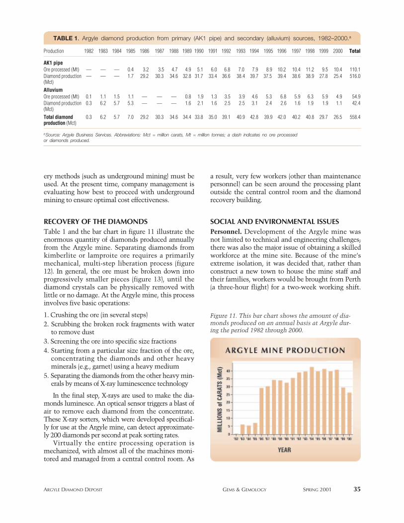
ery methods (such as underground mining) must beused. At the present time, company management isevaluating how best to proceed with undergroundmining to ensure optimal cost effectiveness.
RECOVERY OF THE DIAMONDSTable 1 and the bar chart in figure 11 illustrate theenormous quantity of diamonds produced annuallyfrom the Argyle mine. Separating diamonds fromkimberlite or lamproite ore requires a primarilymechanical, multi-step liberation process (figure12). In general, the ore must be broken down intoprogressively smaller pieces (figure 13), until thediamond crystals can be physically removed withlittle or no damage. At the Argyle mine, this processinvolves five basic operations:
1. Crushing the ore (in several steps)2. Scrubbing the broken rock fragments with water
to remove dust3. Screening the ore into specific size fractions 4. Starting from a particular size fraction of the ore,
concentrating the diamonds and other heavyminerals (e.g., garnet) using a heavy medium
5. Separating the diamonds from the other heavy min-erals by means of X-ray luminescence technology
In the final step, X-rays are used to make the dia-monds luminesce. An optical sensor triggers a blast ofair to remove each diamond from the concentrate.These X-ray sorters, which were developed specifical-ly for use at the Argyle mine, can detect approximate-ly 200 diamonds per second at peak sorting rates.
Virtually the entire processing operation ismechanized, with almost all of the machines moni-tored and managed from a central control room. As
a result, very few workers (other than maintenancepersonnel) can be seen around the processing plantoutside the central control room and the diamondrecovery building.
SOCIAL AND ENVIRONMENTAL ISSUES Personnel. Development of the Argyle mine wasnot limited to technical and engineering challenges;there was also the major issue of obtaining a skilledworkforce at the mine site. Because of the mine’sextreme isolation, it was decided that, rather thanconstruct a new town to house the mine staff andtheir families, workers would be brought from Perth(a three-hour flight) for a two-week working shift.
ARGYLE DIAMOND DEPOSIT GEMS & GEMOLOGY SPRING 2001 35
TABLE 1. Argyle diamond production from primary (AK1 pipe) and secondary (alluvium) sources, 1982–2000.a
Production 1982 1983 1984 1985 1986 1987 1988 1989 1990 1991 1992 1993 1994 1995 1996 1997 1998 1999 2000 Total
AK1 pipeOre processed (Mt) — — — 0.4 3.2 3.5 4.7 4.9 5.1 6.0 6.8 7.0 7.9 8.9 10.2 10.4 11.2 9.5 10.4 110.1Diamond production — — — 1.7 29.2 30.3 34.6 32.8 31.7 33.4 36.6 38.4 39.7 37.5 39.4 38.6 38.9 27.8 25.4 516.0(Mct)AlluviumOre processed (Mt) 0.1 1.1 1.5 1.1 — — — 0.8 1.9 1.3 3.5 3.9 4.6 5.3 6.8 5.9 6.3 5.9 4.9 54.9Diamond production 0.3 6.2 5.7 5.3 — — — 1.6 2.1 1.6 2.5 2.5 3.1 2.4 2.6 1.6 1.9 1.9 1.1 42.4(Mct)Total diamond 0.3 6.2 5.7 7.0 29.2 30.3 34.6 34.4 33.8 35.0 39.1 40.9 42.8 39.9 42.0 40.2 40.8 29.7 26.5 558.4production (Mct)
aSource: Argyle Business Services. Abbreviations: Mct = million carats, Mt = million tonnes; a dash indicates no ore processedor diamonds produced.
Figure 11. This bar chart shows the amount of dia-monds produced on an annual basis at Argyle dur-ing the period 1982 through 2000.
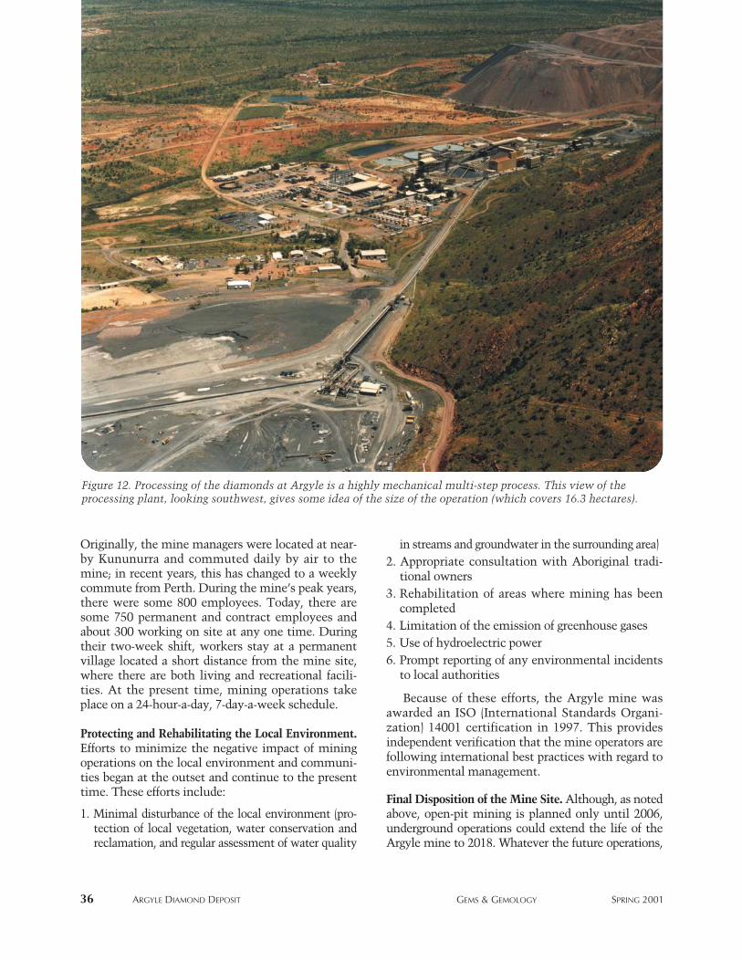
Originally, the mine managers were located at near-by Kununurra and commuted daily by air to themine; in recent years, this has changed to a weeklycommute from Perth. During the mine’s peak years,there were some 800 employees. Today, there aresome 750 permanent and contract employees andabout 300 working on site at any one time. Duringtheir two-week shift, workers stay at a permanentvillage located a short distance from the mine site,where there are both living and recreational facili-ties. At the present time, mining operations takeplace on a 24-hour-a-day, 7-day-a-week schedule.
Protecting and Rehabilitating the Local Environment.Efforts to minimize the negative impact of miningoperations on the local environment and communi-ties began at the outset and continue to the presenttime. These efforts include:
1. Minimal disturbance of the local environment (pro-tection of local vegetation, water conservation andreclamation, and regular assessment of water quality
in streams and groundwater in the surrounding area)2. Appropriate consultation with Aboriginal tradi-
tional owners3. Rehabilitation of areas where mining has been
completed4. Limitation of the emission of greenhouse gases 5. Use of hydroelectric power6. Prompt reporting of any environmental incidents
to local authorities
Because of these efforts, the Argyle mine wasawarded an ISO (International Standards Organi-zation) 14001 certification in 1997. This providesindependent verification that the mine operators arefollowing international best practices with regard toenvironmental management.
Final Disposition of the Mine Site. Although, as notedabove, open-pit mining is planned only until 2006,underground operations could extend the life of theArgyle mine to 2018. Whatever the future operations,
36 ARGYLE DIAMOND DEPOSIT GEMS & GEMOLOGY SPRING 2001
Figure 12. Processing of the diamonds at Argyle is a highly mechanical multi-step process. This view of theprocessing plant, looking southwest, gives some idea of the size of the operation (which covers 16.3 hectares).
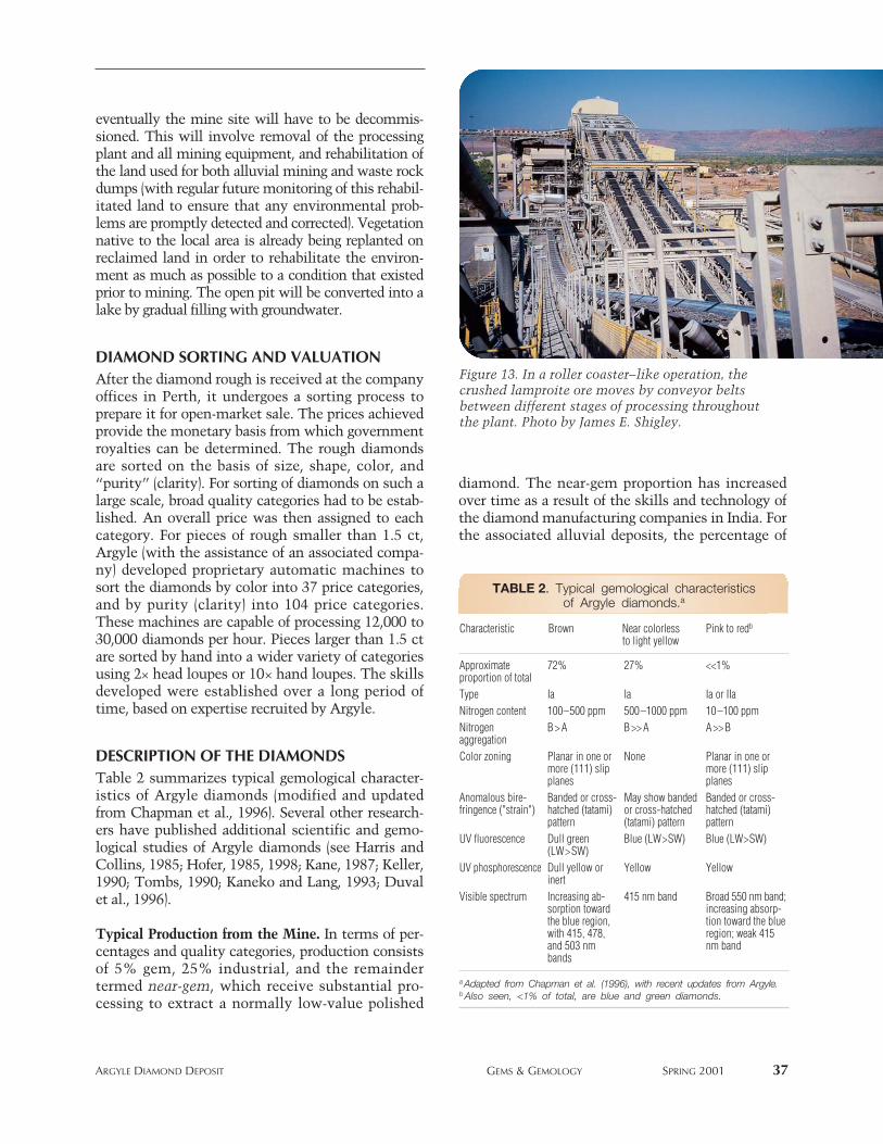
eventually the mine site will have to be decommis-sioned. This will involve removal of the processingplant and all mining equipment, and rehabilitation ofthe land used for both alluvial mining and waste rockdumps (with regular future monitoring of this rehabil-itated land to ensure that any environmental prob-lems are promptly detected and corrected). Vegetationnative to the local area is already being replanted onreclaimed land in order to rehabilitate the environ-ment as much as possible to a condition that existedprior to mining. The open pit will be converted into alake by gradual filling with groundwater.
DIAMOND SORTING AND VALUATIONAfter the diamond rough is received at the companyoffices in Perth, it undergoes a sorting process toprepare it for open-market sale. The prices achievedprovide the monetary basis from which governmentroyalties can be determined. The rough diamondsare sorted on the basis of size, shape, color, and“purity” (clarity). For sorting of diamonds on such alarge scale, broad quality categories had to be estab-lished. An overall price was then assigned to eachcategory. For pieces of rough smaller than 1.5 ct,Argyle (with the assistance of an associated compa-ny) developed proprietary automatic machines tosort the diamonds by color into 37 price categories,and by purity (clarity) into 104 price categories.These machines are capable of processing 12,000 to30,000 diamonds per hour. Pieces larger than 1.5 ctare sorted by hand into a wider variety of categoriesusing 2× head loupes or 10× hand loupes. The skillsdeveloped were established over a long period oftime, based on expertise recruited by Argyle.
DESCRIPTION OF THE DIAMONDSTable 2 summarizes typical gemological character-istics of Argyle diamonds (modified and updatedfrom Chapman et al., 1996). Several other research-ers have published additional scientific and gemo-logical studies of Argyle diamonds (see Harris andCollins, 1985; Hofer, 1985, 1998; Kane, 1987; Keller,1990; Tombs, 1990; Kaneko and Lang, 1993; Duvalet al., 1996).
Typical Production from the Mine. In terms of per-centages and quality categories, production consistsof 5% gem, 25% industrial, and the remaindertermed near-gem, which receive substantial pro-cessing to extract a normally low-value polished
diamond. The near-gem proportion has increasedover time as a result of the skills and technology ofthe diamond manufacturing companies in India. Forthe associated alluvial deposits, the percentage of
ARGYLE DIAMOND DEPOSIT GEMS & GEMOLOGY SPRING 2001 37
TABLE 2. Typical gemological characteristicsof Argyle diamonds.a
Characteristic Brown Near colorless Pink to redb
to light yellow
Approximate 72% 27% <<1%proportion of totalType Ia Ia Ia or IIaNitrogen content 100–500 ppm 500–1000 ppm 10–100 ppmNitrogen B > A B >> A A >> BaggregationColor zoning Planar in one or None Planar in one or
more (111) slip more (111) slipplanes planes
Anomalous bire- Banded or cross- May show banded Banded or cross-fringence ("strain") hatched (tatami) or cross-hatched hatched (tatami)
pattern (tatami) pattern patternUV fluorescence Dull green Blue (LW>SW) Blue (LW>SW)
(LW>SW)UV phosphorescence Dull yellow or Yellow Yellow
inertVisible spectrum Increasing ab- 415 nm band Broad 550 nm band;
sorption toward increasing absorp-the blue region, tion toward the blue with 415, 478, region; weak 415 and 503 nm nm bandbands
aAdapted from Chapman et al. (1996), with recent updates from Argyle.bAlso seen, <1% of total, are blue and green diamonds.
Figure 13. In a roller coaster–like operation, thecrushed lamproite ore moves by conveyor beltsbetween different stages of processing throughoutthe plant. Photo by James E. Shigley.
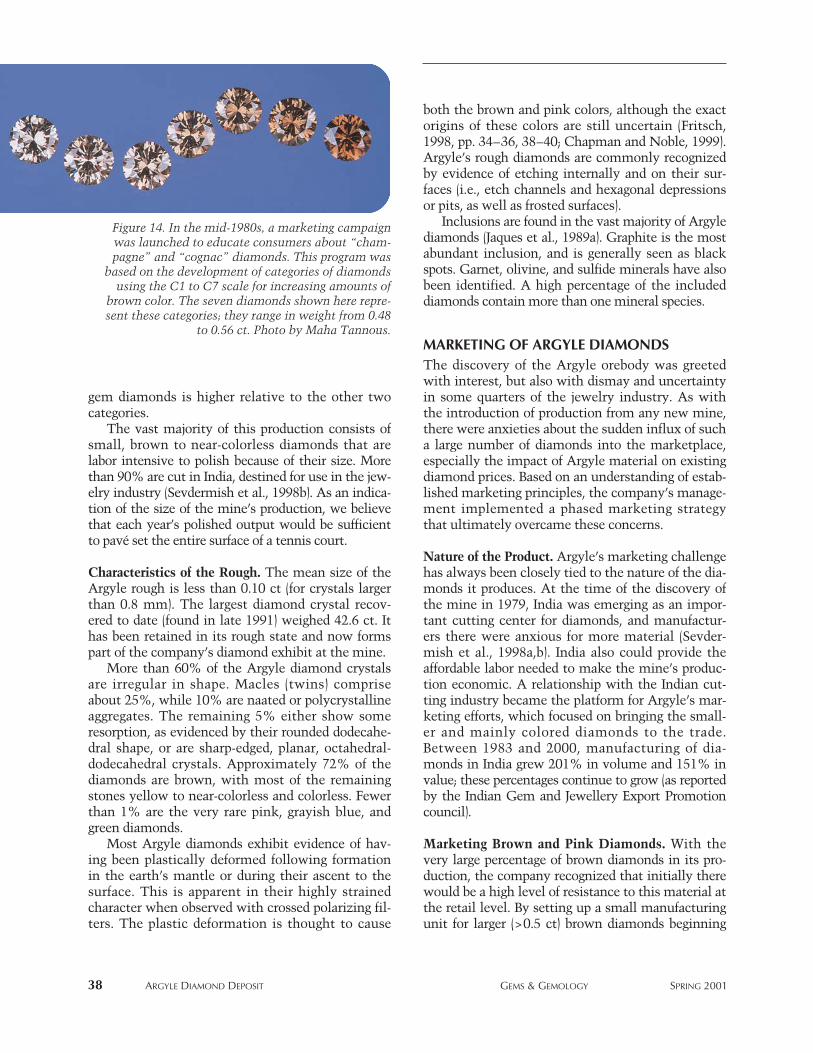
gem diamonds is higher relative to the other twocategories.
The vast majority of this production consists ofsmall, brown to near-colorless diamonds that arelabor intensive to polish because of their size. Morethan 90% are cut in India, destined for use in the jew-elry industry (Sevdermish et al., 1998b). As an indica-tion of the size of the mine’s production, we believethat each year’s polished output would be sufficientto pavé set the entire surface of a tennis court.
Characteristics of the Rough. The mean size of theArgyle rough is less than 0.10 ct (for crystals largerthan 0.8 mm). The largest diamond crystal recov-ered to date (found in late 1991) weighed 42.6 ct. Ithas been retained in its rough state and now formspart of the company’s diamond exhibit at the mine.
More than 60% of the Argyle diamond crystalsare irregular in shape. Macles (twins) compriseabout 25%, while 10% are naated or polycrystallineaggregates. The remaining 5% either show someresorption, as evidenced by their rounded dodecahe-dral shape, or are sharp-edged, planar, octahedral-dodecahedral crystals. Approximately 72% of thediamonds are brown, with most of the remainingstones yellow to near-colorless and colorless. Fewerthan 1% are the very rare pink, grayish blue, andgreen diamonds.
Most Argyle diamonds exhibit evidence of hav-ing been plastically deformed following formationin the earth’s mantle or during their ascent to thesurface. This is apparent in their highly strainedcharacter when observed with crossed polarizing fil-ters. The plastic deformation is thought to cause
both the brown and pink colors, although the exactorigins of these colors are still uncertain (Fritsch,1998, pp. 34–36, 38–40; Chapman and Noble, 1999).Argyle’s rough diamonds are commonly recognizedby evidence of etching internally and on their sur-faces (i.e., etch channels and hexagonal depressionsor pits, as well as frosted surfaces).
Inclusions are found in the vast majority of Argylediamonds (Jaques et al., 1989a). Graphite is the mostabundant inclusion, and is generally seen as blackspots. Garnet, olivine, and sulfide minerals have alsobeen identified. A high percentage of the includeddiamonds contain more than one mineral species.
MARKETING OF ARGYLE DIAMONDSThe discovery of the Argyle orebody was greetedwith interest, but also with dismay and uncertaintyin some quarters of the jewelry industry. As withthe introduction of production from any new mine,there were anxieties about the sudden influx of sucha large number of diamonds into the marketplace,especially the impact of Argyle material on existingdiamond prices. Based on an understanding of estab-lished marketing principles, the company’s manage-ment implemented a phased marketing strategythat ultimately overcame these concerns.
Nature of the Product. Argyle’s marketing challengehas always been closely tied to the nature of the dia-monds it produces. At the time of the discovery ofthe mine in 1979, India was emerging as an impor-tant cutting center for diamonds, and manufactur-ers there were anxious for more material (Sevder-mish et al., 1998a,b). India also could provide theaffordable labor needed to make the mine’s produc-tion economic. A relationship with the Indian cut-ting industry became the platform for Argyle’s mar-keting efforts, which focused on bringing the small-er and mainly colored diamonds to the trade.Between 1983 and 2000, manufacturing of dia-monds in India grew 201% in volume and 151% invalue; these percentages continue to grow (as reportedby the Indian Gem and Jewellery Export Promotioncouncil).
Marketing Brown and Pink Diamonds. With thevery large percentage of brown diamonds in its pro-duction, the company recognized that initially therewould be a high level of resistance to this material atthe retail level. By setting up a small manufacturingunit for larger (>0.5 ct) brown diamonds beginning
38 ARGYLE DIAMOND DEPOSIT GEMS & GEMOLOGY SPRING 2001
Figure 14. In the mid-1980s, a marketing campaignwas launched to educate consumers about “cham-pagne” and “cognac” diamonds. This program was
based on the development of categories of diamondsusing the C1 to C7 scale for increasing amounts of
brown color. The seven diamonds shown here repre-sent these categories; they range in weight from 0.48
to 0.56 ct. Photo by Maha Tannous.
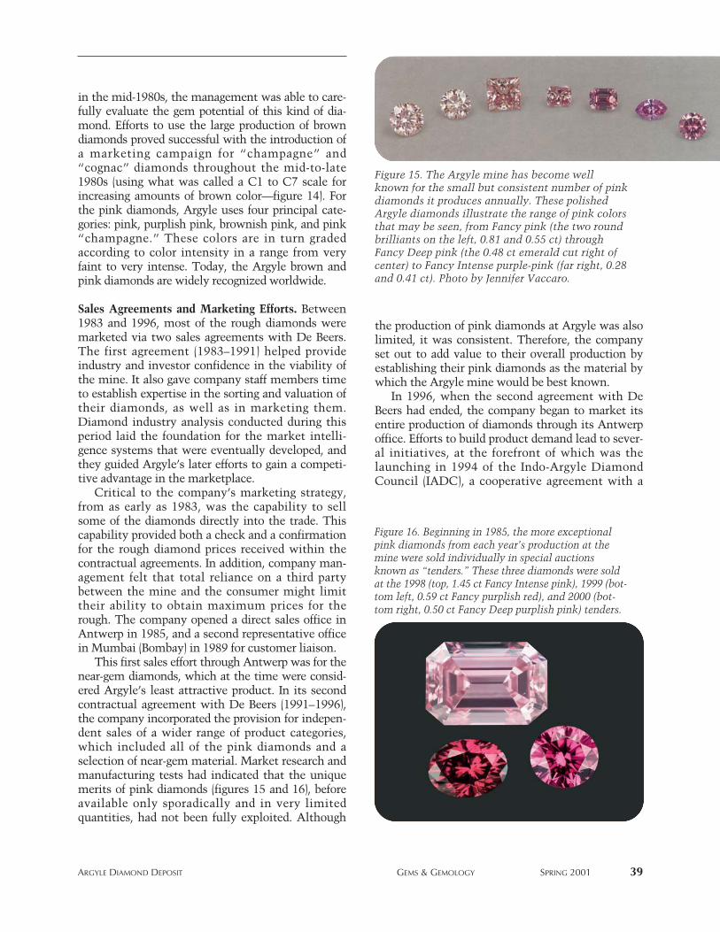
in the mid-1980s, the management was able to care-fully evaluate the gem potential of this kind of dia-mond. Efforts to use the large production of browndiamonds proved successful with the introduction ofa marketing campaign for “champagne” and“cognac” diamonds throughout the mid-to-late1980s (using what was called a C1 to C7 scale forincreasing amounts of brown color—figure 14). Forthe pink diamonds, Argyle uses four principal cate-gories: pink, purplish pink, brownish pink, and pink“champagne.” These colors are in turn gradedaccording to color intensity in a range from veryfaint to very intense. Today, the Argyle brown andpink diamonds are widely recognized worldwide.
Sales Agreements and Marketing Efforts. Between1983 and 1996, most of the rough diamonds weremarketed via two sales agreements with De Beers.The first agreement (1983–1991) helped provideindustry and investor confidence in the viability ofthe mine. It also gave company staff members timeto establish expertise in the sorting and valuation oftheir diamonds, as well as in marketing them.Diamond industry analysis conducted during thisperiod laid the foundation for the market intelli-gence systems that were eventually developed, andthey guided Argyle’s later efforts to gain a competi-tive advantage in the marketplace.
Critical to the company’s marketing strategy,from as early as 1983, was the capability to sellsome of the diamonds directly into the trade. Thiscapability provided both a check and a confirmationfor the rough diamond prices received within thecontractual agreements. In addition, company man-agement felt that total reliance on a third partybetween the mine and the consumer might limittheir ability to obtain maximum prices for therough. The company opened a direct sales office inAntwerp in 1985, and a second representative officein Mumbai (Bombay) in 1989 for customer liaison.
This first sales effort through Antwerp was for thenear-gem diamonds, which at the time were consid-ered Argyle’s least attractive product. In its secondcontractual agreement with De Beers (1991–1996),the company incorporated the provision for indepen-dent sales of a wider range of product categories,which included all of the pink diamonds and aselection of near-gem material. Market research andmanufacturing tests had indicated that the uniquemerits of pink diamonds (figures 15 and 16), beforeavailable only sporadically and in very limitedquantities, had not been fully exploited. Although
the production of pink diamonds at Argyle was alsolimited, it was consistent. Therefore, the companyset out to add value to their overall production byestablishing their pink diamonds as the material bywhich the Argyle mine would be best known.
In 1996, when the second agreement with DeBeers had ended, the company began to market itsentire production of diamonds through its Antwerpoffice. Efforts to build product demand lead to sever-al initiatives, at the forefront of which was thelaunching in 1994 of the Indo-Argyle DiamondCouncil (IADC), a cooperative agreement with a
ARGYLE DIAMOND DEPOSIT GEMS & GEMOLOGY SPRING 2001 39
Figure 16. Beginning in 1985, the more exceptionalpink diamonds from each year’s production at themine were sold individually in special auctionsknown as “tenders.” These three diamonds were soldat the 1998 (top, 1.45 ct Fancy Intense pink), 1999 (bot-tom left, 0.59 ct Fancy purplish red), and 2000 (bot-tom right, 0.50 ct Fancy Deep purplish pink) tenders.
Figure 15. The Argyle mine has become wellknown for the small but consistent number of pinkdiamonds it produces annually. These polishedArgyle diamonds illustrate the range of pink colorsthat may be seen, from Fancy pink (the two roundbrilliants on the left, 0.81 and 0.55 ct) throughFancy Deep pink (the 0.48 ct emerald cut right ofcenter) to Fancy Intense purple-pink (far right, 0.28and 0.41 ct). Photo by Jennifer Vaccaro.
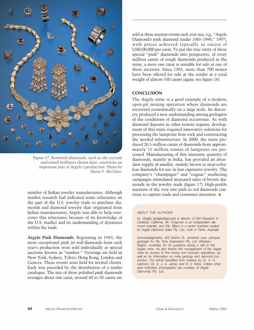
number of Indian jewelry manufacturers. Althoughmarket research had indicated some reluctance onthe part of the U.S. jewelry trade to purchase dia-monds and diamond jewelry that originated fromIndian manufacturers, Argyle was able to help over-come this reluctance because of its knowledge ofthe U.S. market and its understanding of dynamicswithin the trade.
Argyle Pink Diamonds. Beginning in 1985, themore exceptional pink (to red) diamonds from eachyear’s production were sold individually at specialauctions known as “tenders.” Viewings are held inNew York, Sydney, Tokyo, Hong Kong, London andGeneva. These events were held for invited clients.Each was preceded by the distribution of a tendercatalogue. The size of these polished pink diamondsaverages about one carat; around 40 to 50 carats are
sold at these auction events each year (see, e.g., “ArgyleDiamond’s pink diamond tender 1985–1996,” 1997),with prices achieved typically in excess ofUS$100,000 per carat. To put the true rarity of thesespecial “pink” diamonds into perspective, of everymillion carats of rough diamonds produced at themine, a mere one carat is suitable for sale at one ofthese auctions. Since 1985, more than 700 stoneshave been offered for sale at the tender at a totalweight of almost 550 carats (again, see figure 16).
CONCLUSIONThe Argyle mine is a good example of a modern,open-pit mining operation where diamonds arerecovered economically on a large scale. Its discov-ery produced a new understanding among geologistsof the conditions of diamond occurrence. As withdiamond deposits in other remote regions, develop-ment of this mine required innovative solutions forprocessing the lamproite host rock and constructingthe needed infrastructure. In 2000, the mine pro-duced 26.5 million carats of diamonds from approxi-mately 15 million tonnes of lamproite ore pro-cessed. Manufacturing of this immense quantity ofdiamonds, mainly in India, has provided an abun-dant supply of smaller, mainly brown to near-color-less diamonds for use in less expensive jewelry. Thecompany’s “champagne” and “cognac” marketingcampaigns stimulated increased sales of brown dia-monds in the jewelry trade (figure 17). High-profileauctions of the very rare pink to red diamonds con-tinue to capture trade and consumer attention.
40 ARGYLE DIAMOND DEPOSIT GEMS & GEMOLOGY SPRING 2001
Figure 17. Brownish diamonds, such as the crystalsand round brilliants shown here, constitute an
important part of Argyle’s production. Photo byShane F. McClure.
ABOUT THE AUTHORS
Dr. Shigley ([email protected]) is director of GIA Research inCarlsbad, California. Mr. Chapman is an independent dia-mond scientist, and Ms. Ellison is a senior business analystfor Argyle Diamond Sales Pty. Ltd., both in Perth, Australia.
Acknowledgments: JES thanks Dr. Jonathan Lew, principalgeologist for Rio Tinto Exploration Pty. Ltd. (WesternRegion, Australia), for his guidance during a visit to theArgyle mine. He also thanks the management of the Argylemine for access to the mining and recovery operations, aswell as for information on mine geology and diamond pro-duction. The article benefited from reviews by Dr. A. A.Levinson, Dr. A. J. A. Janse, and R. E. Kane. Unless other-wise indicated, photographs are courtesy of ArgyleDiamonds Pty. Ltd.
REFERENCES“Argyle Diamond’s pink diamond tender 1985–1996” (1997)
Australian Gemmologist, Vol. 19, No. 10, pp. 415–418.Atkinson W.J., Smith C.B., Boxer G.L. (1984a) The discovery and
geology of the Argyle diamond deposits, Kimberley, WesternAustralia. Australian Institute of Mining and MetallurgyConference, Darwin, Northern Territory, August, pp.141–149.
Atkinson W.J., Hughes F.E., Smith C.B. (1984b) A review of thekimberlitic rocks of Western Australia. In J. Kornprobst, Ed.,Proceedings of the Third International Kimberlite Conference,Vol. 1—Developments in Petrology 11A, Kimberlites I:Kimberlites and Related Rocks, Clermont-Ferrand, France,1982, Elsevier Publishers, Amsterdam, pp. 195–224.
Boxer G.L., Lorenz V., Smith C.B. (1989) The geology and vol-canology of the Argyle (AK1) lamproite diatreme, WesternAustralia. In J. Ross and others, Eds., Proceedings of theFourth International Kimberlite Conference—Kimberlitesand Related Rocks, Vol. 1, Their Composition, Occurrence,Origin and Emplacement, Perth, 1986, Geological Society ofAustralia Special Publication No. 14, pp. 140–169.
Chapman J., Noble C.J. (1999) Studies of the pink and blue col-oration in Argyle diamonds. Gems & Gemology, Vol. 35, No.3, pp. 156–157.
Chapman J., Browne G., Sechos B. (1996) The typical gemmologi-cal characteristics of Argyle diamonds. Australian Gemmol-ogist, Vol. 19, No. 8, pp. 339–346.
Clifford T.N. (1966) Tectono-metallogenic units and metallo-genic provinces of Africa. Earth and Planetary ScienceLetters, Vol. 1, pp. 421–434.
Deakin A.S., Boxer G.L., Meakins A.E., Haebig A.E., Lew J.H.(1989) Geology of the Argyle alluvial diamond deposits. In J.Ross and others, Eds., Proceedings of the Fourth InternationalKimberlite Conference—Kimberlites and Related Rocks, Vol.2, Their Mantle/Crust Setting, Diamonds and DiamondExploration, Perth, 1986, Geological Society of AustraliaSpecial Publication No. 14, pp. 1108–1116.
Duval D., Green T., Louthean R. (1996) New Frontiers inDiamond—The Mining Revolution. Rosendale Press, London,175 pp.
Fritsch E. (1998) The nature of color in diamonds. In G.E.Harlow, Ed., The Nature of Diamonds, Cambridge UniversityPress, Cambridge, United Kingdom, pp. 23–47.
Geach C. L. (1986) Diamond exploration in Western Australia.Geology Today, Vol. 2, No. 1, pp. 16–20.
Graham S., Lambert D.D., Shee S.H., Smith C.B., Reeves S.(1999). Re-Os isotopic evidence for Archean lithospheric man-tle beneath the Kimberley block, Western Australia. Geology,Vol. 27, No. 5, pp. 431–434.
Haggerty S.E. (1999) A diamond trilogy: Superplumes, supercon-tinents, and supernovae. Science, Vol. 285, No. 5424, pp.851–860.
Harris J.W., Collins A.T. (1985) Studies of Argyle diamonds.Industrial Diamond Review, Vol. 45, No. 3, pp. 128–130.
Hawthorne J.B. (1975) Model of a kimberlite pipe. Physics andChemistry of the Earth, Vol. 9, pp. 1–15.
Hofer S.C. (1985) Pink diamonds from Australia. Gems &Gemology, Vol. 21, No. 3, pp. 145–155.
Hofer S.C. (1998) Collecting and Classifying ColouredDiamonds: An Illustrated Study of the Aurora Collection.Ashland Press, New York, 742 pp.
Janse A.J.A. (1992) The Argyle diamond discovery, Kimberleyregion, Australia. Exploration and Mining Geology, Vol. 1,No. 4, pp. 383–390.
Jaques A.L., Lewis J.D., Smith C.B. (1986) The Kimberlites and
Lamproites of Western Australia. Geological Survey ofWestern Australia, Bulletin 132.
Jaques A.L., Hall A.E., Sheraton J.W., Smith C.B., Sun S.-S., DrewR.M., Foudoulis C., Ellingsen K. (1989a) Composition of crys-talline inclusions and C-isotopic composition of Argyle andEllendale diamonds. In J. Ross and others, Eds., Proceedings ofthe Fourth International Kimberlite Conference—Kimberlitesand Related Rocks, Vol. 2, Their Mantle/Crust Setting,Diamonds and Diamond Exploration, Perth, 1986, GeologicalSociety of Australia Special Publication No. 14, pp. 966–989.
Jaques A.L., Sun S.-S., Chappell B.W. (1989b) Geochemistry ofthe Argyle (AK1) lamproite pipe, Western Australia. In J. Rossand others, Eds., Proceedings of the Fourth InternationalKimberlite Conference—Kimberlites and Related Rocks, Vol.1, Their Composition, Occurrence, Origin and Emplacement,Perth, 1986, Geological Society of Australia SpecialPublication No. 14, pp. 170–188.
Jaques A.L., Haggerty S.E., Lucas H., Boxer G.L. (1989c)Mineralogy and petrology of the Argyle (AK1) lamproite pipe,Western Australia. In J. Ross and others, Eds., Proceedings ofthe Fourth International Kimberlite Conference—Kimber-lites and Related Rocks, Vol. 1, Their Composition, Occur-rence, Origin and Emplacement, Perth, 1986, GeologicalSociety of Australia Special Publication No. 14, pp. 153–169.
Kane R.E. (1987) Three notable fancy-color diamonds: Purplishred, purple-pink, and reddish purple. Gems & Gemology, Vol.23, No. 2, pp. 90–95.
Kaneko K., Lang A.R. (1993) CL and optical microtopographicstudies of Argyle diamonds. Industrial Diamond Review, Vol.53, No. 6, pp. 334–337.
Keller P.C. (1990) Gemstones and Their Origins. Van NostrandReinhold, New York, pp. 144.
Kirkley M.B., Gurney J.J., Levinson A.A. (1991) Age, origin, andemplacement of diamonds. Gems & Gemology, Vol. 27, No.1, pp. 2–25.
Mitchell R.H. (1986) Kimberlites: Mineralogy, Geochemistry,and Petrology. Plenum Publishers, New York.
Mitchell R.H. (1989) Aspects of the petrology of kimberlites andlamproites: Some definitions and distinctions. In J. Ross andothers, Eds., Proceedings of the Fourth InternationalKimberlite Conference—Kimberlites and Related Rocks, Vol.1, Their Composition, Occurrence, Origin and Emplacement,Perth, 1986, Geological Society of Australia Special Pub-lication No. 14, pp. 7–45.
Pidgeon R.T., Smith C.B., Fanning C.M. (1989) Kimberlite andlamproite emplacement ages in Western Australia. In J. Rosset al., Eds., Proceedings of the Fourth InternationalKimberlite Conference—Kimberlites and Related Rocks, Vol.1, Their Composition, Occurrence, Origin and Emplacement,Perth, 1986, Geological Society of Australia SpecialPublication No. 14, pp. 369–381.
Prider R.T. (1960) The leucite-lamproites of the Fitzroy Basin,Western Australia. Journal of the Geological Society ofAustralia, Vol. 6, Pt. 2, pp. 71–120.
Sevdermish M., Miciak A.R., Levinson A.A. (1998a) The dia-mond pipeline into the third millennium: A multi-channelfrom the mine to the consumer. Geoscience Canada, Vol. 25,No. 2, pp. 71–84.
Sevdermish M., Miciak A.R., Levinson A.A. (1998b) The rise toprominence of the modern diamond cutting industry in India.Gems & Gemology, Vol. 34, No. 1, pp. 4–23.
Smith R. (1996) Jewel of the Kimberley: Unearthing the world’slargest diamond producer. Australian Geographic, No. 41, pp.88–107.
Tombs G.A. (1990) Argyle diamonds. Australian Gemmologist,Vol. 17, No. 8, pp. 321–324.
ARGYLE DIAMOND DEPOSIT GEMS & GEMOLOGY SPRING 2001 41
HYDROTHERMAL SYNTHETICRED BERYL FROM THE INSTITUTE OF
CRYSTALLOGRAPHY, MOSCOW
42 SYNTHETIC RED BERYL GEMS & GEMOLOGY SPRING 2001
both natural and synthetic, plus Ti, Co, and Ni insynthetic beryls; Sinkankas, 1981; Fritsch andRossman, 1987). These elements substitute for Al.Alkali elements (Li, Na, K, Rb, Cs) can also occur inminor amounts by substituting for Be and Al(Sinkankas, 1981; Aurisicchio et al., 1988; Deer etal., 1997, pp. 378–386); however, these elements donot affect beryl coloration. The beryl crystal struc-ture contains two different sites along “open” chan-nels that can incorporate water molecules (Schalleret al., 1962; Wood and Nassau, 1968; Schmetzer,1989; Deer et al., 1997). These variations in transi-tion metal, alkali element, and water contents inberyls cause differences in physical properties (suchas refractive index, specific gravity, and color), aswell as in visible and infrared absorption spectra.
Natural Red Beryl. Gem-quality red beryl occurs ata single locality in the Wah Wah Mountains ofsouthern Utah (see, e.g., Flamini et al., 1983;
By James E. Shigley, Shane F. McClure, Jo-Ellen Cole, John I. Koivula,Taijin Lu, Shane Elen, and Ludmila N. Demianets
See end of article for About the Authors information and acknowledgments.GEMS & GEMOLOGY, Vol. 37, No. 1, pp. 42–55© 2001 Gemological Institute of America
Hydrothermal synthetic red beryl has been produced for jewelry applications by the Institute ofCrystallography and an affiliated company, Emcom Ltd., both in Moscow. Diagnostic identification fea-tures include: a tabular crystal morphology, chevron-like and subparallel or slightly wavy internal growthzoning, sharp absorption bands at approximately 530, 545, 560, 570, and 590 nm due to Co2+, water-related absorption bands between 4200 and 3200 cm-1 in the infrared spectrum, and the presence of Coand Ni peaks in EDXRF spectra.
ydrothermal synthetic red beryl from severalsources in Russia has been sold commercial-ly since the mid-1990s, as faceted stones up
to several carats (see, e.g., figure 1). This articledescribes material produced by a private company(Emcom Ltd.) in affiliation with the Institute ofCrystallography at the Russian Academy of Sciencesin Moscow. The rarity, high value, and commercialinterest in natural red beryl from Utah no doubt con-tributed initially to the goal of producing and market-ing a synthetic counterpart. Today, limited demandfor this color of synthetic beryl has curtailed produc-tion at the Institute of Crystallography, as well as byother producers (pers., comm., 2001: WalterBarshai—Pinky Trading Co., Los Angeles; AlexGrizenko—Russian Colored Stone Co., Golden,Colorado; Uriah Prichard—Morion Co., Brighton,Massachusetts). Nevertheless, synthetic red berylcontinues to circulate in the marketplace.
BACKGROUNDBeryl Crystal Chemistry. Pure beryl (Be3Al2Si6O18) iscolorless. The presence of other elements gives riseto various colors (Fe, Cr, V, and Mn for coloration in
H
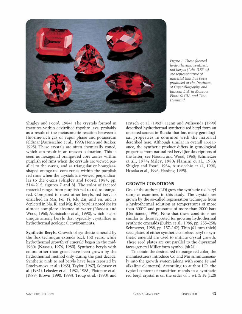
SYNTHETIC RED BERYL GEMS & GEMOLOGY SPRING 2001 43
Shigley and Foord, 1984). The crystals formed infractures within devitrified rhyolite lava, probablyas a result of the metasomatic reaction between afluorine-rich gas or vapor phase and potassiumfeldspar (Aurisicchio et al., 1990; Henn and Becker,1995). These crystals are often chemically zoned,which can result in an uneven coloration. This isseen as hexagonal orange-red core zones withinpurplish red rims when the crystals are viewed par-allel to the c-axis, and as triangular or hourglass-shaped orange-red core zones within the purplishred rims when the crystals are viewed perpendicu-lar to the c-axis (Shigley and Foord, 1984, pp.214–215, figures 7 and 8). The color of facetedmaterial ranges from purplish red to red to orange-red. Compared to most other beryls, red beryl isenriched in Mn, Fe, Ti, Rb, Zn, and Sn, and isdepleted in Na, K, and Mg. Red beryl is noted for itsalmost complete absence of water (Nassau andWood, 1968; Aurisicchio et al., 1990), which is alsounique among beryls that typically crystallize inhydrothermal geological environments.
Synthetic Beryls. Growth of synthetic emerald bythe flux technique extends back 150 years, whilehydrothermal growth of emerald began in the mid-1960s (Nassau, 1976, 1980). Synthetic beryls withcolors other than green have been grown by thehydrothermal method only during the past decade.Synthetic pink to red beryls have been reported byEmel’yanova et al. (1965), Taylor (1967), Solntsev etal. (1981), Lebedev et al. (1982, 1983), Platonov et al.(1989), Brown (1990, 1993), Troup et al. (1990), and
Fritsch et al. (1992). Henn and Milisenda (1999)described hydrothermal synthetic red beryl from anunstated source in Russia that has many gemologi-cal properties in common with the materialdescribed here. Although similar in overall appear-ance, the synthetic product differs in gemologicalproperties from natural red beryl (for descriptions ofthe latter, see Nassau and Wood, 1968; Schmetzeret al., 1974; Miley, 1980; Flamini et al., 1983;Shigley and Foord, 1984; Aurisicchio et al., 1990;Hosaka et al., 1993; Harding, 1995).
GROWTH CONDITIONSOne of the authors (LD) grew the synthetic red berylsamples examined in this study. The crystals aregrown by the so-called regeneration technique froma hydrothermal solution at temperatures of morethan 600°C and pressures of more than 2000 bars(Demianets, 1996). Note that these conditions aresimilar to those reported for growing hydrothermalsynthetic emeralds (Bukin et al., 1986, pp. 255–258;Schmetzer, 1988, pp. 157–162). Thin (≤1 mm thick)seed plates of either synthetic colorless beryl or syn-thetic emerald are used to initiate crystal growth.These seed plates are cut parallel to the dipyramidfaces (general Miller form symbol {hk2i—l}).
To obtain the desired red to orange-red color, themanufacturers introduce Co and Mn simultaneous-ly into the growth system (along with some Fe andalkaline elements). According to author LD, thetypical content of transition metals in a syntheticred beryl crystal is on the order of 1 wt.% Fe (1.28
Figure 1. These facetedhydrothermal syntheticred beryls (1.46–3.85 ct)are representative ofmaterial that has beenproduced at the Instituteof Crystallography andEmcom Ltd. in Moscow.Photo © GIA and TinoHammid.
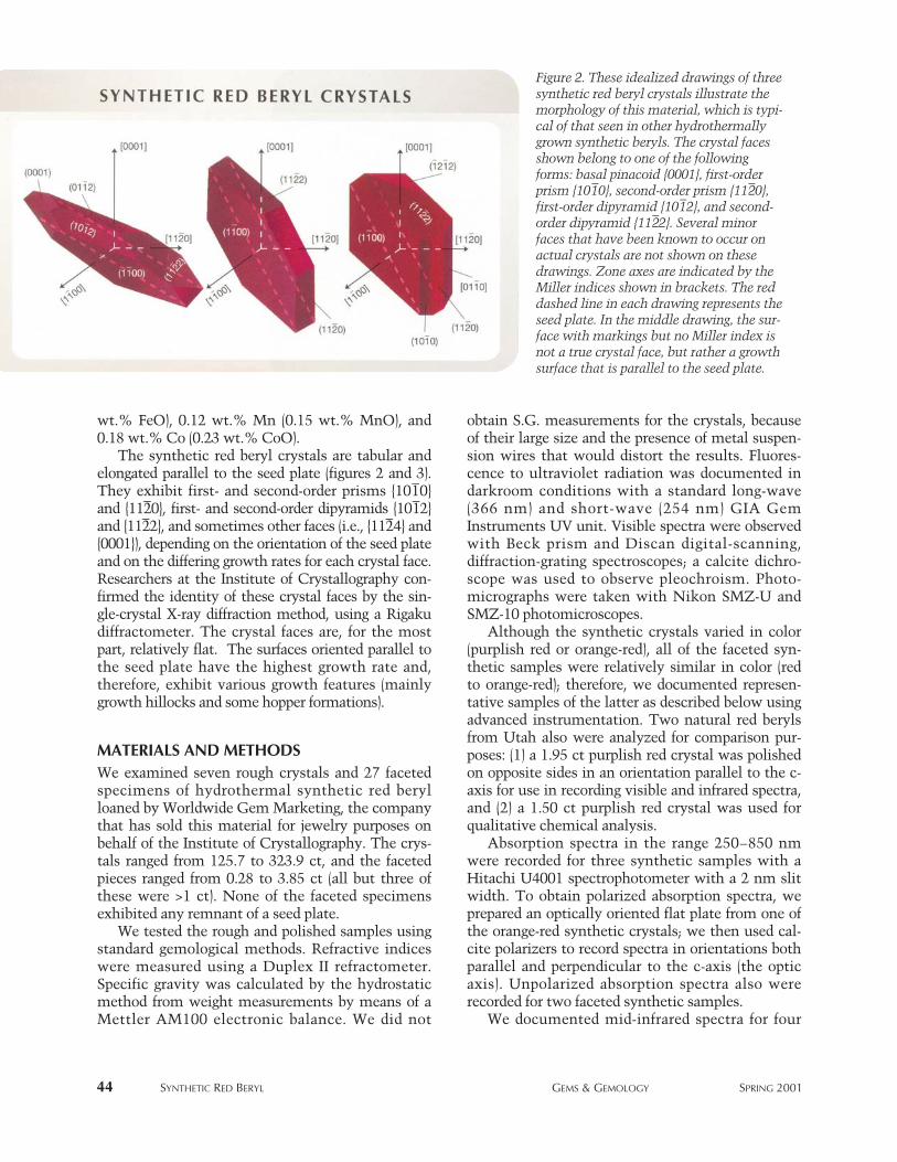
44 SYNTHETIC RED BERYL GEMS & GEMOLOGY SPRING 2001
Figure 2. These idealized drawings of threesynthetic red beryl crystals illustrate themorphology of this material, which is typi-cal of that seen in other hydrothermallygrown synthetic beryls. The crystal facesshown belong to one of the followingforms: basal pinacoid {0001}, first-orderprism {101
–0}, second-order prism {112
–0},
first-order dipyramid {101–2}, and second-
order dipyramid {112–2}. Several minor
faces that have been known to occur onactual crystals are not shown on thesedrawings. Zone axes are indicated by theMiller indices shown in brackets. The reddashed line in each drawing represents theseed plate. In the middle drawing, the sur-face with markings but no Miller index isnot a true crystal face, but rather a growthsurface that is parallel to the seed plate.
wt.% FeO), 0.12 wt.% Mn (0.15 wt.% MnO), and0.18 wt.% Co (0.23 wt.% CoO).
The synthetic red beryl crystals are tabular andelongated parallel to the seed plate (figures 2 and 3).They exhibit first- and second-order prisms {101–0}and {112–0}, first- and second-order dipyramids {101–2}and {112–2}, and sometimes other faces (i.e., {112–4} and{0001}), depending on the orientation of the seed plateand on the differing growth rates for each crystal face.Researchers at the Institute of Crystallography con-firmed the identity of these crystal faces by the sin-gle-crystal X-ray diffraction method, using a Rigakudiffractometer. The crystal faces are, for the mostpart, relatively flat. The surfaces oriented parallel tothe seed plate have the highest growth rate and,therefore, exhibit various growth features (mainlygrowth hillocks and some hopper formations).
MATERIALS AND METHODSWe examined seven rough crystals and 27 facetedspecimens of hydrothermal synthetic red berylloaned by Worldwide Gem Marketing, the companythat has sold this material for jewelry purposes onbehalf of the Institute of Crystallography. The crys-tals ranged from 125.7 to 323.9 ct, and the facetedpieces ranged from 0.28 to 3.85 ct (all but three ofthese were >1 ct). None of the faceted specimensexhibited any remnant of a seed plate.
We tested the rough and polished samples usingstandard gemological methods. Refractive indiceswere measured using a Duplex II refractometer.Specific gravity was calculated by the hydrostaticmethod from weight measurements by means of aMettler AM100 electronic balance. We did not
obtain S.G. measurements for the crystals, becauseof their large size and the presence of metal suspen-sion wires that would distort the results. Fluores-cence to ultraviolet radiation was documented indarkroom conditions with a standard long-wave(366 nm) and short-wave (254 nm) GIA GemInstruments UV unit. Visible spectra were observedwith Beck prism and Discan digital-scanning,diffraction-grating spectroscopes; a calcite dichro-scope was used to observe pleochroism. Photo-micrographs were taken with Nikon SMZ-U andSMZ-10 photomicroscopes.
Although the synthetic crystals varied in color(purplish red or orange-red), all of the faceted syn-thetic samples were relatively similar in color (redto orange-red); therefore, we documented represen-tative samples of the latter as described below usingadvanced instrumentation. Two natural red berylsfrom Utah also were analyzed for comparison pur-poses: (1) a 1.95 ct purplish red crystal was polishedon opposite sides in an orientation parallel to the c-axis for use in recording visible and infrared spectra,and (2) a 1.50 ct purplish red crystal was used forqualitative chemical analysis.
Absorption spectra in the range 250–850 nmwere recorded for three synthetic samples with aHitachi U4001 spectrophotometer with a 2 nm slitwidth. To obtain polarized absorption spectra, weprepared an optically oriented flat plate from one ofthe orange-red synthetic crystals; we then used cal-cite polarizers to record spectra in orientations bothparallel and perpendicular to the c-axis (the opticaxis). Unpolarized absorption spectra also wererecorded for two faceted synthetic samples.
We documented mid-infrared spectra for four
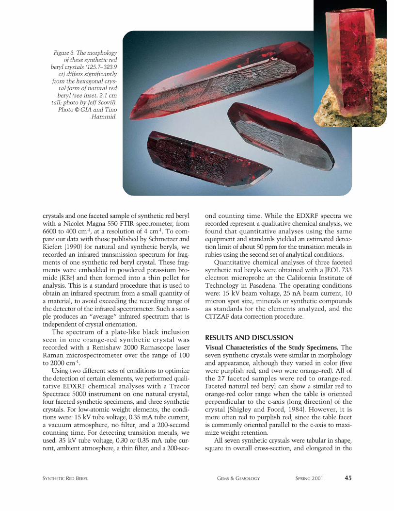
SYNTHETIC RED BERYL GEMS & GEMOLOGY SPRING 2001 45
Figure 3. The morphologyof these synthetic red
beryl crystals (125.7–323.9ct) differs significantly
from the hexagonal crys-tal form of natural redberyl (see inset, 2.1 cm
tall; photo by Jeff Scovil).Photo © GIA and Tino
Hammid.
crystals and one faceted sample of synthetic red berylwith a Nicolet Magna 550 FTIR spectrometer, from6600 to 400 cm-1, at a resolution of 4 cm-1. To com-pare our data with those published by Schmetzer andKiefert (1990) for natural and synthetic beryls, werecorded an infrared transmission spectrum for frag-ments of one synthetic red beryl crystal. These frag-ments were embedded in powdered potassium bro-mide (KBr) and then formed into a thin pellet foranalysis. This is a standard procedure that is used toobtain an infrared spectrum from a small quantity ofa material, to avoid exceeding the recording range ofthe detector of the infrared spectrometer. Such a sam-ple produces an “average” infrared spectrum that isindependent of crystal orientation.
The spectrum of a plate-like black inclusionseen in one orange-red synthetic crystal wasrecorded with a Renishaw 2000 Ramascope laserRaman microspectrometer over the range of 100to 2000 cm-1.
Using two different sets of conditions to optimizethe detection of certain elements, we performed quali-tative EDXRF chemical analyses with a TracorSpectrace 5000 instrument on one natural crystal,four faceted synthetic specimens, and three syntheticcrystals. For low-atomic weight elements, the condi-tions were: 15 kV tube voltage, 0.35 mA tube current,a vacuum atmosphere, no filter, and a 200-secondcounting time. For detecting transition metals, weused: 35 kV tube voltage, 0.30 or 0.35 mA tube cur-rent, ambient atmosphere, a thin filter, and a 200-sec-
ond counting time. While the EDXRF spectra werecorded represent a qualitative chemical analysis, wefound that quantitative analyses using the sameequipment and standards yielded an estimated detec-tion limit of about 50 ppm for the transition metals inrubies using the second set of analytical conditions.
Quantitative chemical analyses of three facetedsynthetic red beryls were obtained with a JEOL 733electron microprobe at the California Institute ofTechnology in Pasadena. The operating conditionswere: 15 kV beam voltage, 25 nA beam current, 10micron spot size, minerals or synthetic compoundsas standards for the elements analyzed, and theCITZAF data correction procedure.
RESULTS AND DISCUSSION Visual Characteristics of the Study Specimens. Theseven synthetic crystals were similar in morphologyand appearance, although they varied in color (fivewere purplish red, and two were orange–red). All ofthe 27 faceted samples were red to orange-red.Faceted natural red beryl can show a similar red toorange-red color range when the table is orientedperpendicular to the c-axis (long direction) of thecrystal (Shigley and Foord, 1984). However, it ismore often red to purplish red, since the table facetis commonly oriented parallel to the c-axis to maxi-mize weight retention.
All seven synthetic crystals were tabular in shape,square in overall cross-section, and elongated in the
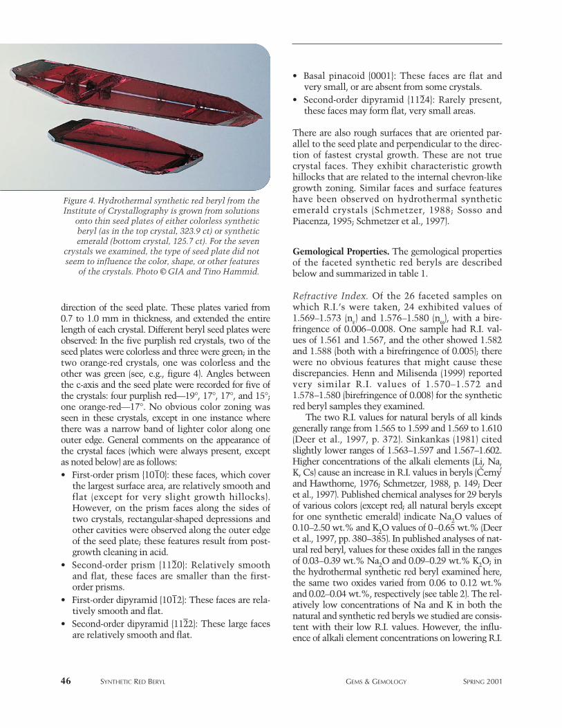
direction of the seed plate. These plates varied from0.7 to 1.0 mm in thickness, and extended the entirelength of each crystal. Different beryl seed plates wereobserved: In the five purplish red crystals, two of theseed plates were colorless and three were green; in thetwo orange-red crystals, one was colorless and theother was green (see, e.g., figure 4). Angles betweenthe c-axis and the seed plate were recorded for five ofthe crystals: four purplish red—19°, 17°, 17°, and 15°;one orange-red—17°. No obvious color zoning wasseen in these crystals, except in one instance wherethere was a narrow band of lighter color along oneouter edge. General comments on the appearance ofthe crystal faces (which were always present, exceptas noted below) are as follows:• First-order prism {101–0}: these faces, which cover
the largest surface area, are relatively smooth andflat (except for very slight growth hillocks).However, on the prism faces along the sides oftwo crystals, rectangular-shaped depressions andother cavities were observed along the outer edgeof the seed plate; these features result from post-growth cleaning in acid.
• Second-order prism {112–0}: Relatively smoothand flat, these faces are smaller than the first-order prisms.
• First-order dipyramid {101–2}: These faces are rela-tively smooth and flat.
• Second-order dipyramid {112–2}: These large facesare relatively smooth and flat.
• Basal pinacoid {0001}: These faces are flat andvery small, or are absent from some crystals.
• Second-order dipyramid {112–4}: Rarely present,these faces may form flat, very small areas.
There are also rough surfaces that are oriented par-allel to the seed plate and perpendicular to the direc-tion of fastest crystal growth. These are not truecrystal faces. They exhibit characteristic growthhillocks that are related to the internal chevron-likegrowth zoning. Similar faces and surface featureshave been observed on hydrothermal syntheticemerald crystals (Schmetzer, 1988; Sosso andPiacenza, 1995; Schmetzer et al., 1997).
Gemological Properties. The gemological propertiesof the faceted synthetic red beryls are describedbelow and summarized in table 1.
Refractive Index. Of the 26 faceted samples onwhich R.I.’s were taken, 24 exhibited values of1.569–1.573 (nε) and 1.576–1.580 (nω), with a bire-fringence of 0.006–0.008. One sample had R.I. val-ues of 1.561 and 1.567, and the other showed 1.582and 1.588 (both with a birefringence of 0.005); therewere no obvious features that might cause thesediscrepancies. Henn and Milisenda (1999) reportedvery similar R.I. values of 1.570–1.572 and1.578–1.580 (birefringence of 0.008) for the syntheticred beryl samples they examined.
The two R.I. values for natural beryls of all kindsgenerally range from 1.565 to 1.599 and 1.569 to 1.610(Deer et al., 1997, p. 372). Sinkankas (1981) citedslightly lower ranges of 1.563–1.597 and 1.567–1.602.Higher concentrations of the alkali elements (Li, Na,K, Cs) cause an increase in R.I. values in beryls (C
verny’
and Hawthorne, 1976; Schmetzer, 1988, p. 149; Deeret al., 1997). Published chemical analyses for 29 berylsof various colors (except red; all natural beryls exceptfor one synthetic emerald) indicate Na2O values of0.10–2.50 wt.% and K2O values of 0–0.65 wt.% (Deeret al., 1997, pp. 380–385). In published analyses of nat-ural red beryl, values for these oxides fall in the rangesof 0.03–0.39 wt.% Na2O and 0.09–0.29 wt.% K2O; inthe hydrothermal synthetic red beryl examined here,the same two oxides varied from 0.06 to 0.12 wt.%and 0.02–0.04 wt.%, respectively (see table 2). The rel-atively low concentrations of Na and K in both thenatural and synthetic red beryls we studied are consis-tent with their low R.I. values. However, the influ-ence of alkali element concentrations on lowering R.I.
46 SYNTHETIC RED BERYL GEMS & GEMOLOGY SPRING 2001
Figure 4. Hydrothermal synthetic red beryl from theInstitute of Crystallography is grown from solutions
onto thin seed plates of either colorless syntheticberyl (as in the top crystal, 323.9 ct) or syntheticemerald (bottom crystal, 125.7 ct). For the seven
crystals we examined, the type of seed plate did notseem to influence the color, shape, or other features
of the crystals. Photo © GIA and Tino Hammid.
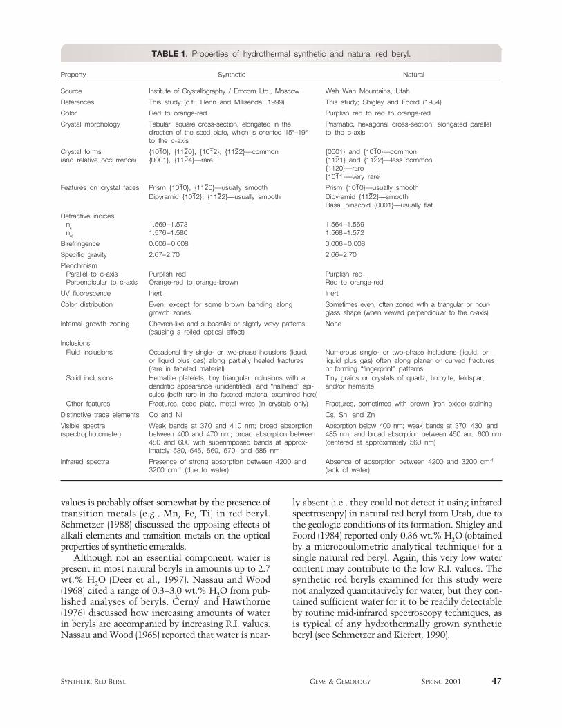
values is probably offset somewhat by the presence oftransition metals (e.g., Mn, Fe, Ti) in red beryl.Schmetzer (1988) discussed the opposing effects ofalkali elements and transition metals on the opticalproperties of synthetic emeralds.
Although not an essential component, water ispresent in most natural beryls in amounts up to 2.7wt.% H2O (Deer et al., 1997). Nassau and Wood(1968) cited a range of 0.3–3.0 wt.% H2O from pub-lished analyses of beryls. C
verny’ and Hawthorne
(1976) discussed how increasing amounts of waterin beryls are accompanied by increasing R.I. values.Nassau and Wood (1968) reported that water is near-
ly absent (i.e., they could not detect it using infraredspectroscopy) in natural red beryl from Utah, due tothe geologic conditions of its formation. Shigley andFoord (1984) reported only 0.36 wt.% H2O (obtainedby a microcoulometric analytical technique) for asingle natural red beryl. Again, this very low watercontent may contribute to the low R.I. values. Thesynthetic red beryls examined for this study werenot analyzed quantitatively for water, but they con-tained sufficient water for it to be readily detectableby routine mid-infrared spectroscopy techniques, asis typical of any hydrothermally grown syntheticberyl (see Schmetzer and Kiefert, 1990).
SYNTHETIC RED BERYL GEMS & GEMOLOGY SPRING 2001 47
TABLE 1. Properties of hydrothermal synthetic and natural red beryl.
Property Synthetic Natural
Source Institute of Crystallography / Emcom Ltd., Moscow Wah Wah Mountains, Utah
References This study (c.f., Henn and Milisenda, 1999) This study; Shigley and Foord (1984)
Color Red to orange-red Purplish red to red to orange-red
Crystal morphology Tabular, square cross-section, elongated in the Prismatic, hexagonal cross-section, elongated paralleldirection of the seed plate, which is oriented 15°–19° to the c-axisto the c-axis
Crystal forms {101–0}, {112–0}, {101–2}, {112–2}—common {0001} and {101–0}—common(and relative occurrence) {0001}, {112–4}—rare {112–1} and {112–2}—less common
{112–0}—rare{101–1}—very rare
Features on crystal faces Prism {101–0}, {112–0}—usually smooth Prism {101–0}—usually smoothDipyramid {101–2}, {112–2}—usually smooth Dipyramid {112–2}—smooth
Basal pinacoid {0001}—usually flat
Refractive indicesnε 1.569–1.573 1.564–1.569nω 1.576–1.580 1.568–1.572
Birefringence 0.006–0.008 0.006–0.008
Specific gravity 2.67–2.70 2.66–2.70
PleochroismParallel to c-axis Purplish red Purplish redPerpendicular to c-axis Orange-red to orange-brown Red to orange-red
UV fluorescence Inert Inert
Color distribution Even, except for some brown banding along Sometimes even, often zoned with a triangular or hour-growth zones glass shape (when viewed perpendicular to the c-axis)
Internal growth zoning Chevron-like and subparallel or slightly wavy patterns None(causing a roiled optical effect)
InclusionsFluid inclusions Occasional tiny single- or two-phase inclusions (liquid, Numerous single- or two-phase inclusions (liquid, or
or liquid plus gas) along partially healed fractures liquid plus gas) often along planar or curved fractures(rare in faceted material) or forming “fingerprint” patterns
Solid inclusions Hematite platelets, tiny triangular inclusions with a Tiny grains or crystals of quartz, bixbyite, feldspar, dendritic appearance (unidentified), and “nailhead” spi- and/or hematitecules (both rare in the faceted material examined here)
Other features Fractures, seed plate, metal wires (in crystals only) Fractures, sometimes with brown (iron oxide) staining
Distinctive trace elements Co and Ni Cs, Sn, and Zn
Visible spectra Weak bands at 370 and 410 nm; broad absorption Absorption below 400 nm; weak bands at 370, 430, and(spectrophotometer) between 400 and 470 nm; broad absorption between 485 nm; and broad absorption between 450 and 600 nm
480 and 600 with superimposed bands at approx- (centered at approximately 560 nm)imately 530, 545, 560, 570, and 585 nm
Infrared spectra Presence of strong absorption between 4200 and Absence of absorption between 4200 and 3200 cm-1
3200 cm-1 (due to water) (lack of water)
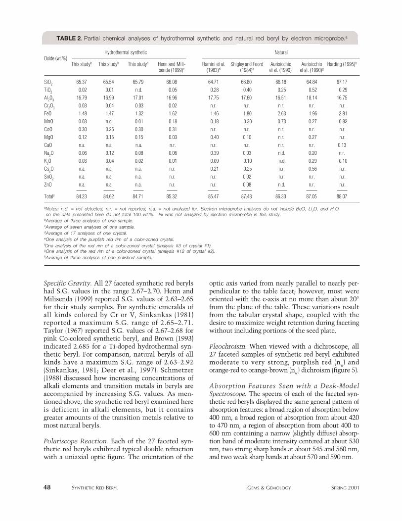
Specific Gravity. All 27 faceted synthetic red berylshad S.G. values in the range 2.67–2.70. Henn andMilisenda (1999) reported S.G. values of 2.63–2.65for their study samples. For synthetic emeralds ofall kinds colored by Cr or V, Sinkankas (1981)reported a maximum S.G. range of 2.65–2.71.Taylor (1967) reported S.G. values of 2.67–2.68 forpink Co-colored synthetic beryl, and Brown (1993)indicated 2.685 for a Ti-doped hydrothermal syn-thetic beryl. For comparison, natural beryls of allkinds have a maximum S.G. range of 2.63–2.92(Sinkankas, 1981; Deer et al., 1997). Schmetzer(1988) discussed how increasing concentrations ofalkali elements and transition metals in beryls areaccompanied by increasing S.G. values. As men-tioned above, the synthetic red beryl examined hereis deficient in alkali elements, but it containsgreater amounts of the transition metals relative tomost natural beryls.
Polariscope Reaction. Each of the 27 faceted syn-thetic red beryls exhibited typical double refractionwith a uniaxial optic figure. The orientation of the
optic axis varied from nearly parallel to nearly per-pendicular to the table facet; however, most wereoriented with the c-axis at no more than about 20°from the plane of the table. These variations resultfrom the tabular crystal shape, coupled with thedesire to maximize weight retention during facetingwithout including portions of the seed plate.
Pleochroism. When viewed with a dichroscope, all27 faceted samples of synthetic red beryl exhibitedmoderate to very strong, purplish red (ne) andorange-red to orange-brown (nw) dichroism (figure 5).
Absorption Features Seen with a Desk-ModelSpectroscope. The spectra of each of the faceted syn-thetic red beryls displayed the same general pattern ofabsorption features: a broad region of absorption below400 nm, a broad region of absorption from about 420to 470 nm, a region of absorption from about 400 to600 nm containing a narrow (slightly diffuse) absorp-tion band of moderate intensity centered at about 530nm, two strong sharp bands at about 545 and 560 nm,and two weak sharp bands at about 570 and 590 nm.
48 SYNTHETIC RED BERYL GEMS & GEMOLOGY SPRING 2001
TABLE 2. Partial chemical analyses of hydrothermal synthetic and natural red beryl by electron microprobe.a
Hydrothermal synthetic Natural
This studyb This studyb This studyb Henn and Mili- Flamini et al. Shigley and Foord Aurisicchio Aurisicchio Harding (1995)h
senda (1999)c (1983)d (1984)e et al. (1990)f et al. (1990)g
SiO2 65.37 65.54 65.79 66.08 64.71 66.80 66.18 64.84 67.17TiO2 0.02 0.01 n.d. 0.05 0.28 0.40 0.25 0.52 0.29Al2O3 16.79 16.99 17.01 16.96 17.75 17.60 16.51 18.14 16.75Cr2O3 0.03 0.04 0.03 0.02 n.r. n.r. n.r. n.r. n.r.FeO 1.48 1.47 1.32 1.62 1.46 1.80 2.63 1.96 2.81MnO 0.03 n.d. 0.01 0.18 0.18 0.30 0.73 0.27 0.82CoO 0.30 0.26 0.30 0.31 n.r. n.r. n.r. n.r. n.r.MgO 0.12 0.15 0.15 0.03 0.40 0.10 n.r. 0.27 n.r.CaO n.a. n.a. n.a. n.r. n.r. n.r. n.r. n.r. 0.13Na2O 0.06 0.12 0.08 0.06 0.39 0.03 n.d. 0.20 n.r.K2O 0.03 0.04 0.02 0.01 0.09 0.10 n.d. 0.29 0.10Cs2O n.a. n.a. n.a. n.r. 0.21 0.25 n.r. 0.56 n.r.SnO2 n.a. n.a. n.a. n.r. n.r. 0.02 n.r. n.r. n.r.ZnO n.a. n.a. n.a. n.r. n.r. 0.08 n.d. n.r. n.r.
Totala 84.23 84.62 84.71 85.32 85.47 87.48 86.30 87.05 88.07
aNotes: n.d. = not detected, n.r. = not reported, n.a. = not analyzed for. Electron microprobe analyses do not include BeO, Li2O, and H2O,so the data presented here do not total 100 wt.%. Ni was not analyzed by electron microprobe in this study.
bAverage of three analyses of one sample.cAverage of seven analyses of one sample.dAverage of 17 analyses of one crystal.eOne analysis of the purplish red rim of a color-zoned crystal.fOne analysis of the red rim of a color-zoned crystal (analysis #3 of crystal #1).gOne analysis of the red rim of a color-zoned crystal (analysis #12 of crystal #2).hAverage of three analyses of one polished sample.
Oxide (wt.%)

This pattern is quite different from the spec-trum of the natural red beryl we examined,which showed an intense region of absorptionbelow about 450 nm and a broad absorptionbetween about 540 and 580 nm. Thus, the pres-ence of several diffuse-to-sharp absorption bandsbetween 530 and 590 nm (due to Co2+) is distinc-tive of this hydrothermal synthetic red beryl.
Internal Characteristics. Examination of the crystalsand faceted samples of synthetic red beryl with abinocular microscope revealed the following features:
1. Prominent internal growth zoning (figure 6) wasoriented at an oblique angle to the seed plate.According to Schmetzer (1988), this kind of zon-ing in hydrothermal synthetic beryls arises fromthe growth of a number of subparallel “crystal-lites” at an oblique angle to the seed plate. Theirintersection produces chevron-like microstruc-tures, which are best seen when the sample isviewed perpendicular to the plane of the seedplate. He noted that this internal growth zoningalso gives rise to a roiled optical effect.
2. A subparallel or slightly wavy pattern (sometimesbrownish) was best seen when the samples wereexamined parallel to the seed plate direction (fig-ure 7); it is related to the internal growth zoningmentioned above. When the samples were viewedwith crossed polarizers, a strain pattern that mim-ics this growth zoning was evident (figure 8).
3. Remnants of the metal wire used to suspend thecrystals during growth may be present at one orboth ends of the crystals; these were not seen inthe faceted samples.
4. Occasional small, partially healed fractures—usu-ally planar or curved in shape, but sometimes inmore complicated patterns—contained tiny liquid
SYNTHETIC RED BERYL GEMS & GEMOLOGY SPRING 2001 49
Figure 5. The synthetic red beryls studied showedmoderate to very strong dichroism. When viewedtable-down, this 0.75 ct triangle shape displayed pur-plish red and orange-brown pleochroic colors. Photo-micrograph by James Shigley; magnified 3×.
Figure 6. The most distinctive visual feature of the hydrothermal synthetic red beryls examined waschevron-like internal growth zoning. From observations in the original crystals, we know that thiszoning is oriented along the direction of crystal growth at a high, oblique angle to the plane of the seedplate. Photomicrographs by James Shigley; left—magnified 3×, right—magnified 9×.
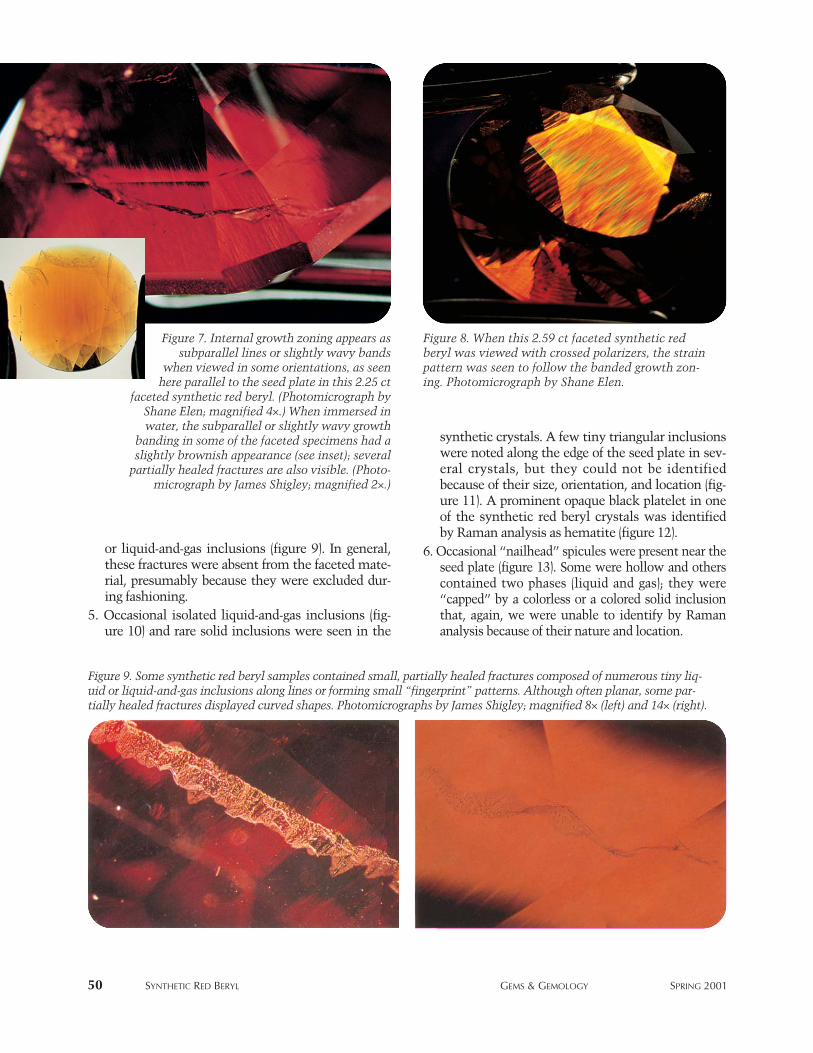
50 SYNTHETIC RED BERYL GEMS & GEMOLOGY SPRING 2001
or liquid-and-gas inclusions (figure 9). In general,these fractures were absent from the faceted mate-rial, presumably because they were excluded dur-ing fashioning.
5. Occasional isolated liquid-and-gas inclusions (fig-ure 10) and rare solid inclusions were seen in the
synthetic crystals. A few tiny triangular inclusionswere noted along the edge of the seed plate in sev-eral crystals, but they could not be identifiedbecause of their size, orientation, and location (fig-ure 11). A prominent opaque black platelet in oneof the synthetic red beryl crystals was identifiedby Raman analysis as hematite (figure 12).
6. Occasional “nailhead” spicules were present near theseed plate (figure 13). Some were hollow and otherscontained two phases (liquid and gas); they were“capped” by a colorless or a colored solid inclusionthat, again, we were unable to identify by Ramananalysis because of their nature and location.
Figure 7. Internal growth zoning appears assubparallel lines or slightly wavy bands
when viewed in some orientations, as seenhere parallel to the seed plate in this 2.25 ct
faceted synthetic red beryl. (Photomicrograph byShane Elen; magnified 4×.) When immersed inwater, the subparallel or slightly wavy growth
banding in some of the faceted specimens had aslightly brownish appearance (see inset); several
partially healed fractures are also visible. (Photo-micrograph by James Shigley; magnified 2×.)
Figure 8. When this 2.59 ct faceted synthetic redberyl was viewed with crossed polarizers, the strainpattern was seen to follow the banded growth zon-ing. Photomicrograph by Shane Elen.
Figure 9. Some synthetic red beryl samples contained small, partially healed fractures composed of numerous tiny liq-uid or liquid-and-gas inclusions along lines or forming small “fingerprint” patterns. Although often planar, some par-tially healed fractures displayed curved shapes. Photomicrographs by James Shigley; magnified 8× (left) and 14× (right).
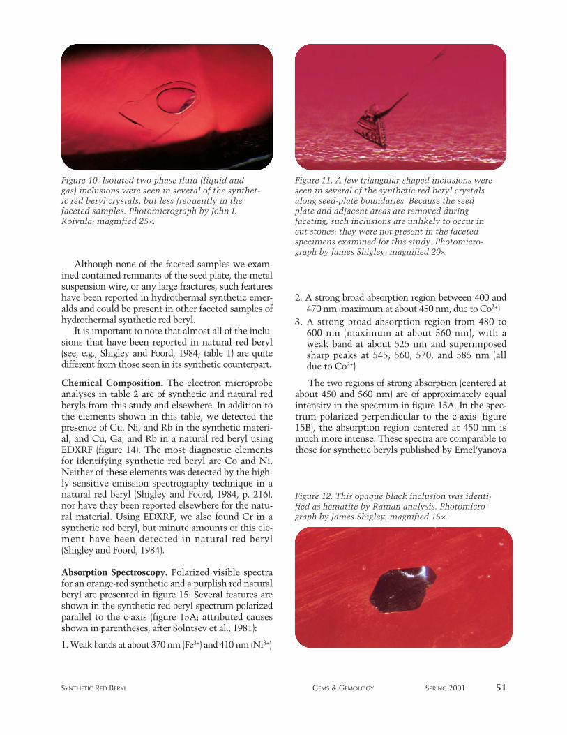
Although none of the faceted samples we exam-ined contained remnants of the seed plate, the metalsuspension wire, or any large fractures, such featureshave been reported in hydrothermal synthetic emer-alds and could be present in other faceted samples ofhydrothermal synthetic red beryl.
It is important to note that almost all of the inclu-sions that have been reported in natural red beryl(see, e.g., Shigley and Foord, 1984; table 1) are quitedifferent from those seen in its synthetic counterpart.
Chemical Composition. The electron microprobeanalyses in table 2 are of synthetic and natural redberyls from this study and elsewhere. In addition tothe elements shown in this table, we detected thepresence of Cu, Ni, and Rb in the synthetic materi-al, and Cu, Ga, and Rb in a natural red beryl usingEDXRF (figure 14). The most diagnostic elementsfor identifying synthetic red beryl are Co and Ni.Neither of these elements was detected by the high-ly sensitive emission spectrography technique in anatural red beryl (Shigley and Foord, 1984, p. 216),nor have they been reported elsewhere for the natu-ral material. Using EDXRF, we also found Cr in asynthetic red beryl, but minute amounts of this ele-ment have been detected in natural red beryl(Shigley and Foord, 1984).
Absorption Spectroscopy. Polarized visible spectrafor an orange-red synthetic and a purplish red naturalberyl are presented in figure 15. Several features areshown in the synthetic red beryl spectrum polarizedparallel to the c-axis (figure 15A; attributed causesshown in parentheses, after Solntsev et al., 1981):
1. Weak bands at about 370 nm (Fe3+) and 410 nm (Ni3+)
2. A strong broad absorption region between 400 and470 nm (maximum at about 450 nm, due to Co2+)
3. A strong broad absorption region from 480 to600 nm (maximum at about 560 nm), with aweak band at about 525 nm and superimposedsharp peaks at 545, 560, 570, and 585 nm (alldue to Co2+)
The two regions of strong absorption (centered atabout 450 and 560 nm) are of approximately equalintensity in the spectrum in figure 15A. In the spec-trum polarized perpendicular to the c-axis (figure15B), the absorption region centered at 450 nm ismuch more intense. These spectra are comparable tothose for synthetic beryls published by Emel’yanova
SYNTHETIC RED BERYL GEMS & GEMOLOGY SPRING 2001 51
Figure 10. Isolated two-phase fluid (liquid andgas) inclusions were seen in several of the synthet-ic red beryl crystals, but less frequently in thefaceted samples. Photomicrograph by John I.Koivula; magnified 25×.
Figure 11. A few triangular-shaped inclusions wereseen in several of the synthetic red beryl crystalsalong seed-plate boundaries. Because the seedplate and adjacent areas are removed duringfaceting, such inclusions are unlikely to occur incut stones; they were not present in the facetedspecimens examined for this study. Photomicro-graph by James Shigley; magnified 20×.
Figure 12. This opaque black inclusion was identi-fied as hematite by Raman analysis. Photomicro-graph by James Shigley; magnified 15×.
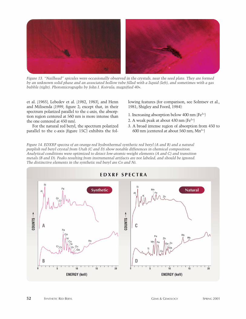
et al. (1965), Lebedev et al. (1982, 1983), and Hennand Milisenda (1999, figure 2; except that, in theirspectrum polarized parallel to the c-axis, the absorp-tion region centered at 560 nm is more intense thanthe one centered at 450 nm).
For the natural red beryl, the spectrum polarizedparallel to the c-axis (figure 15C) exhibits the fol-
lowing features (for comparison, see Solntsev et al.,1981; Shigley and Foord, 1984):
1. Increasing absorption below 400 nm (Fe3+)2. A weak peak at about 430 nm (Fe3+)3. A broad intense region of absorption from 450 to
600 nm (centered at about 560 nm; Mn3+)
52 SYNTHETIC RED BERYL GEMS & GEMOLOGY SPRING 2001
Figure 14. EDXRF spectra of an orange-red hydrothermal synthetic red beryl (A and B) and a naturalpurplish red beryl crystal from Utah (C and D) show notable differences in chemical composition.Analytical conditions were optimized to detect low-atomic-weight elements (A and C) and transitionmetals (B and D). Peaks resulting from instrumental artifacts are not labeled, and should be ignored.The distinctive elements in the synthetic red beryl are Co and Ni.
Figure 13. “Nailhead” spicules were occasionally observed in the crystals, near the seed plate. They are formedby an unknown solid phase and an associated hollow tube filled with a liquid (left), and sometimes with a gasbubble (right). Photomicrographs by John I. Koivula; magnified 40×.
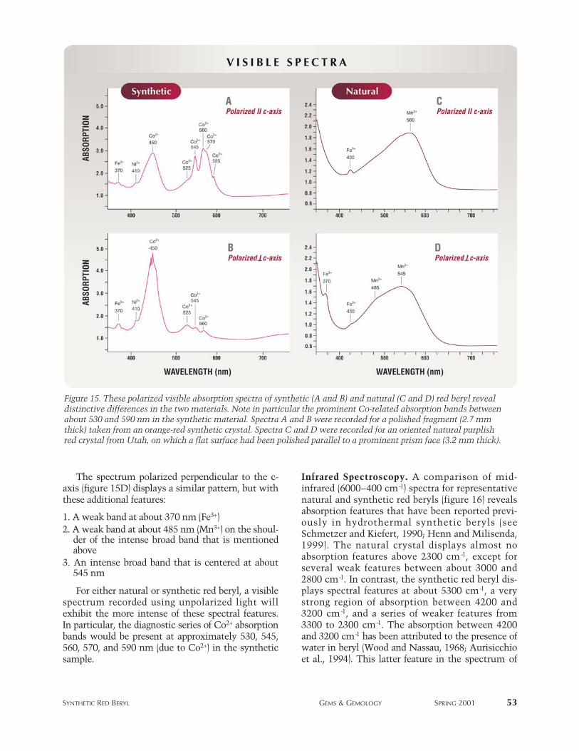
The spectrum polarized perpendicular to the c-axis (figure 15D) displays a similar pattern, but withthese additional features:
1. A weak band at about 370 nm (Fe3+)2. A weak band at about 485 nm (Mn3+) on the shoul-
der of the intense broad band that is mentionedabove
3. An intense broad band that is centered at about545 nm
For either natural or synthetic red beryl, a visiblespectrum recorded using unpolarized light willexhibit the more intense of these spectral features.In particular, the diagnostic series of Co2+ absorptionbands would be present at approximately 530, 545,560, 570, and 590 nm (due to Co2+) in the syntheticsample.
Infrared Spectroscopy. A comparison of mid-infrared (6000–400 cm-1) spectra for representativenatural and synthetic red beryls (figure 16) revealsabsorption features that have been reported previ-ously in hydrothermal synthetic beryls (seeSchmetzer and Kiefert, 1990; Henn and Milisenda,1999). The natural crystal displays almost noabsorption features above 2300 cm-1, except forseveral weak features between about 3000 and2800 cm-1. In contrast, the synthetic red beryl dis-plays spectral features at about 5300 cm-1, a verystrong region of absorption between 4200 and3200 cm-1, and a series of weaker features from3300 to 2300 cm-1. The absorption between 4200and 3200 cm-1 has been attributed to the presence ofwater in beryl (Wood and Nassau, 1968; Aurisicchioet al., 1994). This latter feature in the spectrum of
SYNTHETIC RED BERYL GEMS & GEMOLOGY SPRING 2001 53
Figure 15. These polarized visible absorption spectra of synthetic (A and B) and natural (C and D) red beryl revealdistinctive differences in the two materials. Note in particular the prominent Co-related absorption bands betweenabout 530 and 590 nm in the synthetic material. Spectra A and B were recorded for a polished fragment (2.7 mmthick) taken from an orange-red synthetic crystal. Spectra C and D were recorded for an oriented natural purplishred crystal from Utah, on which a flat surface had been polished parallel to a prominent prism face (3.2 mm thick).
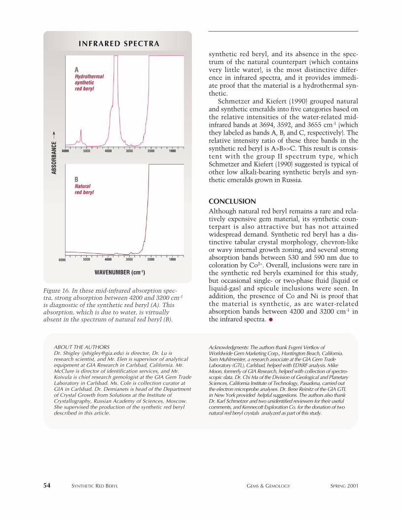
synthetic red beryl, and its absence in the spec-trum of the natural counterpart (which containsvery little water), is the most distinctive differ-ence in infrared spectra, and it provides immedi-ate proof that the material is a hydrothermal syn-thetic.
Schmetzer and Kiefert (1990) grouped naturaland synthetic emeralds into five categories based onthe relative intensities of the water-related mid-infrared bands at 3694, 3592, and 3655 cm-1 (whichthey labeled as bands A, B, and C, respectively). Therelative intensity ratio of these three bands in thesynthetic red beryl is A>B>>C. This result is consis-tent with the group II spectrum type, whichSchmetzer and Kiefert (1990) suggested is typical ofother low alkali-bearing synthetic beryls and syn-thetic emeralds grown in Russia.
CONCLUSIONAlthough natural red beryl remains a rare and rela-tively expensive gem material, its synthetic coun-terpart is also attractive but has not attainedwidespread demand. Synthetic red beryl has a dis-tinctive tabular crystal morphology, chevron-likeor wavy internal growth zoning, and several strongabsorption bands between 530 and 590 nm due tocoloration by Co2+. Overall, inclusions were rare inthe synthetic red beryls examined for this study,but occasional single- or two-phase fluid (liquid orliquid-gas) and spicule inclusions were seen. Inaddition, the presence of Co and Ni is proof thatthe material is synthetic, as are water-relatedabsorption bands between 4200 and 3200 cm-1 inthe infrared spectra.
54 SYNTHETIC RED BERYL GEMS & GEMOLOGY SPRING 2001
ABOUT THE AUTHORSDr. Shigley ([email protected]) is director, Dr. Lu isresearch scientist, and Mr. Elen is supervisor of analyticalequipment at GIA Research in Carlsbad, California. Mr.McClure is director of identification services, and Mr.Koivula is chief research gemologist at the GIA Gem TradeLaboratory in Carlsbad. Ms. Cole is collection curator atGIA in Carlsbad. Dr. Demianets is head of the Departmentof Crystal Growth from Solutions at the Institute ofCrystallography, Russian Academy of Sciences, Moscow.She supervised the production of the synthetic red beryldescribed in this article.
Figure 16. In these mid-infrared absorption spec-tra, strong absorption between 4200 and 3200 cm-1
is diagnostic of the synthetic red beryl (A). Thisabsorption, which is due to water, is virtuallyabsent in the spectrum of natural red beryl (B).
Acknowledgments: The authors thank Evgeni Vertkov ofWorldwide Gem Marketing Corp., Huntington Beach, California.Sam Muhlmeister, a research associate at the GIA Gem TradeLaboratory (GTL), Carlsbad, helped with EDXRF analysis. MikeMoon, formerly of GIA Research, helped with collection of spectro-scopic data. Dr. Chi Ma of the Division of Geological and PlanetarySciences, California Institute of Technology, Pasadena, carried outthe electron microprobe analyses. Dr. Ilene Reinitz of the GIA GTLin New York provided helpful suggestions. The authors also thankDr. Karl Schmetzer and two unidentified reviewers for their usefulcomments, and Kennecott Exploration Co. for the donation of twonatural red beryl crystals analyzed as part of this study.
REFERENCESAurisicchio C., Fioravanti G., Grubessi O., Zanazzi P.F. (1988)
Reappraisal of the crystal chemistry of beryl. AmericanMineralogist, Vol. 73, No. 7/8, pp. 826–837.
Aurisicchio C., Fioravanti G., Grubessi O. (1990) Genesis andgrowth of the red beryl from Utah (U.S.A.). Atti DellaAccademia Nazionale dei Lincei, Rendiconti Lincei,Scienze Fisiche e Naturali, Series 9, Vol. 1, No. 4, pp.393–404.
Aurisicchio C., Grubessi O., Zecchini P. (1994) Infrared spec-troscopy and crystal chemistry of the beryl group. CanadianMineralogist, Vol. 32, Part 1, pp. 55–68.
Brown G. (1990) Biron synthetic pink beryl. Australian Gemmol-ogist, Vol. 17, No. 6, pp. 219–221.
——— (1993) Australian titaniferous synthetic beryl. Journal of theGemmological Association of Hong Kong, Vol. 16, pp. 5–6.
Bukin G.V., Godovikov A.A., Klaykhin V.A., Sobolev V.S. (1986)Growth of emerald single crystals. Growth of Crystals, Vol.13, pp. 251–260.
Cverny’ P., Hawthorne F.C. (1976) Refractive indices versus alkali
contents in beryl: General limitations and applications tosome pegmatitic types. Canadian Mineralogist, Vol. 14, Part4, pp. 491–497.
Deer W.A., Howie R.A., Zussman J. (1997) Rock-forming Minerals,Vol. 1B, Disilicates and Ring Silicates. The Geological Society,London.
Demianets L.N. (1996) Regeneration growth of some hexagonal(trigonal) crystals under hydrothermal conditions. CollectedAbstracts, International Union of Crystallography, 12thCongress and Assembly, Seattle, Washington, August 8–17.
Emel’yanova E.N., Grum-Grzhimailo S.V., Boksha O.N., VarinaT.M. (1965) Artificial beryl containing V, Mn, Co, and Ni.Soviet Physics—Crystallography, Vol. 10, No. 1, pp. 46–49.
Flamini A., Gastaldi L., Grubessi O., Viticoli S. (1983) Sulle carat-teristiche particolari del berillo rosso dell’Utah. La Gemmol-ogia, Vol. 9, No. 1/2, pp. 12–20.
Fritsch E., Rossman G.R. (1987) An update on color in gems. Part1: Introduction and colors caused by dispersed metal ions.Gems & Gemology, Vol. 23, No. 3, pp. 126–139.
Fritsch E., Muhlmeister S., Birkner A. (1992) A preliminary spec-troscopic study of the Biron synthetic pink titanium-beryl.Australian Gemmologist, Vol. 18, No. 3, pp. 81–82.
Harding R.R. (1995) A note on red beryl. Journal of Gemmology,Vol. 24, No. 8, pp. 581–583.
Henn U., Becker G. (1995) Rote Berylle aus Utah, USA–NeueBeobachtungen. Zeitschrift der Deutschen GemmologischenGesellschaft, Vol. 44, No. 2/3, pp. 55–60.
Henn U., Milisenda C.C. (1999) Synthetische rote Berylle ausRussland. Gemmologie: Zeitschrift der Deutschen Gemmolo-gischen Gesellschaft, Vol. 48, No. 2, pp. 97–104.
Hosaka M., Tubokawa K., Hatushika T., Yamashita H. (1993)Observations of red beryl crystals from the Wah Wah Moun-tains, Utah. Journal of Gemmology, Vol. 23, No. 7, pp. 409–411.
Lebedev A.S., Ilyin A.G., Klyakhin V.A. (1982) Hydrothermallygrown beryls of gem quality. Morphology and Phase Equi-
libria of Minerals, International Mineralogical Association,Meeting, Vol. 2, pp. 403–405 (in Russian).
——— (1983) Variétés de béryl “gemme” hydrothermal. Revuede Gemmologie a.f.g., No. 76, pp. 4–5.
Miley F. (1980) An examination of red beryl. Gems & Gemology,Vol. 16, No. 12, pp. 405–408.
Nassau K. (1976) Synthetic emeralds: The confusing historyand current technology. Journal of Crystal Growth, Vol. 35,pp. 211–222.
——— (1980) Gems Made by Man. Chilton Book Co., Radnor, PA. Nassau K., Wood D.L. (1968) An examination of red beryl from
Utah. American Mineralogist, Vol. 53, No. 5/6, pp.801–806.
Platonov A.N., Taran M.N., Klyakhin V.A. (1989) On two colourtypes of Mn3+-bearing beryls. Zeitschrift der DeutschenGemmologischen Gesellschaft, Vol. 38, No. 4, pp. 147–154.
Schaller W.T., Stevens R.E., Jahns R.H. (1962) An unusual berylfrom Arizona. American Mineralogist, Vol. 47, No. 5/6, pp.672–699.
Schmetzer K. (1988) Characterization of Russian hydrothermally-grown synthetic emeralds. Journal of Gemmology, Vol. 21,No. 3, pp. 145–164.
——— (1989) Types of water in natural and synthetic emerald.Neues Jahrbuch für Mineralogie Monatshefte, No. 1, pp. 15–26.
Schmetzer K., Kiefert L. (1990) Water in beryls—A contributionto the separability of natural and synthetic emeralds byinfrared spectroscopy. Journal of Gemmology, Vol. 22, No. 4,pp. 215–223.
Schmetzer K., Bank H., Berdesinski W. (1974) Eine seltene roteVarietät der Mineralart Beryll. Zeitschrift der DeutschenGemmologischen Gesellschaft, Vol. 23, No. 2, pp. 139–141.
Schmetzer K., Kiefert L., Bernhardt H.-J., Beili Z. (1997) Char-acterization of Chinese hydrothermal synthetic emerald.Gems & Gemology, Vol. 33, No. 4, pp. 276–291.
Shigley J.E., Foord E.E. (1984) Gem-quality red beryl from theWah Wah Mountains, Utah. Gems & Gemology, Vol. 20, No.4, pp. 208–221.
Sinkankas J. (1981) Emerald and Other Beryls. Chilton Book Co.,Radnor, PA.
Solntsev V.P., Kharchenko E.I., Lebedev A.S., Klyakhin V.A.,Ilyin A.G. (1981) Nature of color centers and EPR of a man-ganese-activated beryl. Journal of Applied Spectroscopy, Vol.34, No. 1, pp. 111–115.
Sosso F., Piacenza B. (1995) Russian hydrothermal syntheticemeralds: Characterization of the inclusions. Journal ofGemmology, Vol. 24, No. 7, pp. 501–507.
Taylor A.M. (1967) Synthetic cobalt beryl. Journal of Gemmo-logy, Vol. 10, No. 8, pp. 258–261.
Troup G.T., Hutton D.R., Pilbrow J.R. (1990) Electron paramag-netic resonance and fluorescence of Ti3+ in Australian Bironsynthetic beryl. In Abstracts, Australian Institute ofPhysics, 14th Condensed Matter Physics Meeting, WaggaWagga, New South Wales.
Wood D.L., Nassau K. (1968) The characterization of beryl andemerald by visible and infrared absorption spectroscopy.American Mineralogist, Vol. 53, No. 5/6, pp. 777–800.
SYNTHETIC RED BERYL GEMS & GEMOLOGY SPRING 2001 55
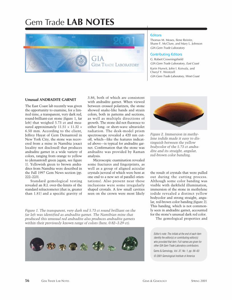
56 GEM TRADE LAB NOTES GEMS & GEMOLOGY SPRING 2001
Unusual ANDRADITE GARNET
The East Coast lab recently was giventhe opportunity to examine, for a lim-ited time, a transparent, very dark red,round-brilliant-cut stone (figure 1, farleft) that weighed 5.73 ct and mea-sured approximately 11.51 × 11.32 ×6.50 mm. According to the client,Jeffrey Hayat of Gem Demantoid inNew York City, the stone was recov-ered from a mine in Namibia (exactlocality not disclosed) that producesandradite garnet in a wide variety ofcolors, ranging from orange to yellowto (demantoid) green (again, see figure1). Yellowish green to brown andra-dites from Namibia were described inthe Fall 1997 Gem News section (pp.222–223).
Standard gemological testingrevealed an R.I. over-the-limits of thestandard refractometer (that is, greaterthan 1.81) and a specific gravity of
3.86, both of which are consistentwith andradite garnet. When viewedbetween crossed polarizers, the stoneshowed snake-like bands and straincolors, both in patterns and sections,as well as multiple directions ofgrowth. The stone did not fluoresce toeither long- or short-wave ultravioletradiation. The desk-model prismspectroscope revealed a 420 nm cut-off, which—like the features indicat-ed above—is typical for andradite gar-net. Confirmation that the stone wasandradite was provided by Ramananalysis.
Microscopic examination revealedsome fractures and fingerprints, aswell as a group of aligned acicularcrystals (several of which were bent atone end to a new set of parallel orien-tations). Also present near theseinclusions were some irregularlyshaped crystals. A few small cavitiesseen on the crown were most likely
the result of crystals that were pulledout during the cutting process.Although some color banding wasvisible with darkfield illumination,immersion of the stone in methyleneiodide revealed a distinct yellowbodycolor and strong straight, angu-lar, red-brown color banding (figure 2).This banding, which is not common-ly seen in andradite garnet, accountedfor the stone’s unusual dark red color.
The gemological properties and
EditorsThomas M. Moses, Ilene Reinitz, Shane F. McClure, and Mary L. JohnsonGIA Gem Trade Laboratory
Contributing EditorsG. Robert CrowningshieldGIA Gem Trade Laboratory, East Coast
Karin Hurwit, John I. Koivula, and Cheryl Y. WentzellGIA Gem Trade Laboratory, West Coast
Gem Trade LAB NOTES
© 2001 Gemological Institute of America
Gems & Gemology, Vol. 37, No. 1, pp. 56–63
Editor’s note: The initials at the end of each itemidentify the editor(s) or contributing editor(s)who provided that item. Full names are given forother GIA Gem Trade Laboratory contributors.
Figure 2. Immersion in methy-lene iodide made it easy to dis-tinguish between the yellowbodycolor of the 5.73 ct andra-dite and its straight, angular,red-brown color banding.
Figure 1. The transparent, very dark red 5.73 ct round brilliant on thefar left was identified as andradite garnet. The Namibian mine thatproduced this unusual red andradite also produces andradite garnetswithin their previously known range of colors (here, 0.82–3.29 ct).
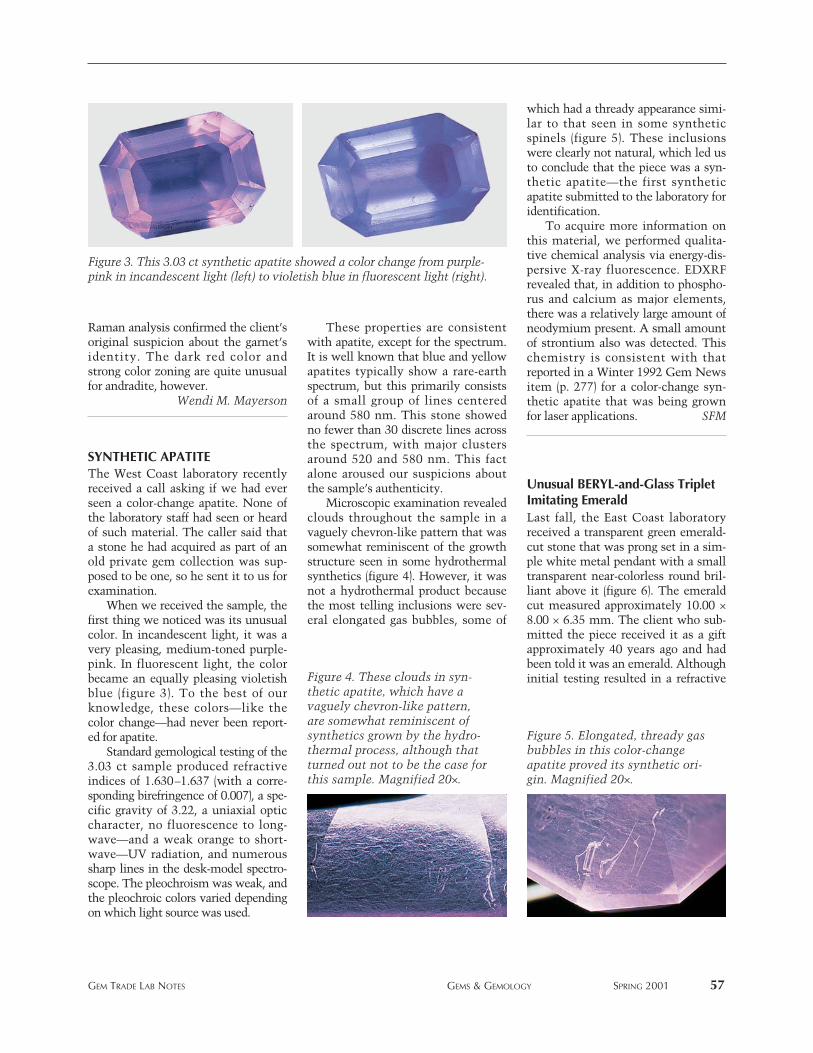
Raman analysis confirmed the client’soriginal suspicion about the garnet’sidentity. The dark red color andstrong color zoning are quite unusualfor andradite, however.
Wendi M. Mayerson
SYNTHETIC APATITEThe West Coast laboratory recentlyreceived a call asking if we had everseen a color-change apatite. None ofthe laboratory staff had seen or heardof such material. The caller said thata stone he had acquired as part of anold private gem collection was sup-posed to be one, so he sent it to us forexamination.
When we received the sample, thefirst thing we noticed was its unusualcolor. In incandescent light, it was avery pleasing, medium-toned purple-pink. In fluorescent light, the colorbecame an equally pleasing violetishblue (figure 3). To the best of ourknowledge, these colors—like thecolor change—had never been report-ed for apatite.
Standard gemological testing of the3.03 ct sample produced refractiveindices of 1.630–1.637 (with a corre-sponding birefringence of 0.007), a spe-cific gravity of 3.22, a uniaxial opticcharacter, no fluorescence to long-wave—and a weak orange to short-wave—UV radiation, and numeroussharp lines in the desk-model spectro-scope. The pleochroism was weak, andthe pleochroic colors varied dependingon which light source was used.
These properties are consistentwith apatite, except for the spectrum.It is well known that blue and yellowapatites typically show a rare-earthspectrum, but this primarily consistsof a small group of lines centeredaround 580 nm. This stone showedno fewer than 30 discrete lines acrossthe spectrum, with major clustersaround 520 and 580 nm. This factalone aroused our suspicions aboutthe sample’s authenticity.
Microscopic examination revealedclouds throughout the sample in avaguely chevron-like pattern that wassomewhat reminiscent of the growthstructure seen in some hydrothermalsynthetics (figure 4). However, it wasnot a hydrothermal product becausethe most telling inclusions were sev-eral elongated gas bubbles, some of
which had a thready appearance simi-lar to that seen in some syntheticspinels (figure 5). These inclusionswere clearly not natural, which led usto conclude that the piece was a syn-thetic apatite—the first syntheticapatite submitted to the laboratory foridentification.
To acquire more information onthis material, we performed qualita-tive chemical analysis via energy-dis-persive X-ray fluorescence. EDXRFrevealed that, in addition to phospho-rus and calcium as major elements,there was a relatively large amount ofneodymium present. A small amountof strontium also was detected. Thischemistry is consistent with thatreported in a Winter 1992 Gem Newsitem (p. 277) for a color-change syn-thetic apatite that was being grownfor laser applications. SFM
Unusual BERYL-and-Glass TripletImitating Emerald Last fall, the East Coast laboratoryreceived a transparent green emerald-cut stone that was prong set in a sim-ple white metal pendant with a smalltransparent near-colorless round bril-liant above it (figure 6). The emeraldcut measured approximately 10.00 ×8.00 × 6.35 mm. The client who sub-mitted the piece received it as a giftapproximately 40 years ago and hadbeen told it was an emerald. Althoughinitial testing resulted in a refractive
GEM TRADE LAB NOTES GEMS & GEMOLOGY SPRING 2001 57
Figure 4. These clouds in syn-thetic apatite, which have avaguely chevron-like pattern,are somewhat reminiscent ofsynthetics grown by the hydro-thermal process, although thatturned out not to be the case forthis sample. Magnified 20×.
Figure 5. Elongated, thready gasbubbles in this color-changeapatite proved its synthetic ori-gin. Magnified 20×.
Figure 3. This 3.03 ct synthetic apatite showed a color change from purple-pink in incandescent light (left) to violetish blue in fluorescent light (right).
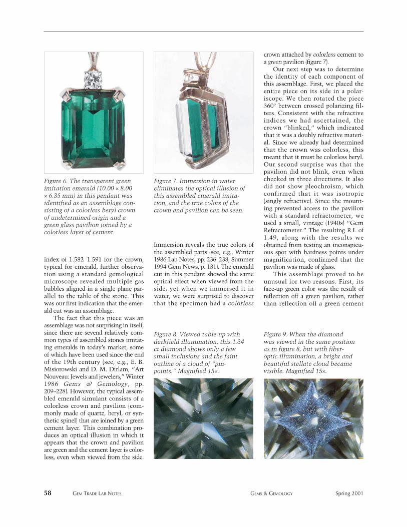
58 GEM TRADE LAB NOTES GEMS & GEMOLOGY Spring 2001
index of 1.582–1.591 for the crown,typical for emerald, further observa-tion using a standard gemologicalmicroscope revealed multiple gasbubbles aligned in a single plane par-allel to the table of the stone. Thiswas our first indication that the emer-ald cut was an assemblage.
The fact that this piece was anassemblage was not surprising in itself,since there are several relatively com-mon types of assembled stones imitat-ing emeralds in today’s market, someof which have been used since the endof the 19th century (see, e.g., E. B.Misiorowski and D. M. Dirlam, “ArtNouveau: Jewels and jewelers,” Winter1986 Gems & Gemology, pp.209–228). However, the typical assem-bled emerald simulant consists of acolorless crown and pavilion (com-monly made of quartz, beryl, or syn-thetic spinel) that are joined by a greencement layer. This combination pro-duces an optical illusion in which itappears that the crown and pavilionare green and the cement layer is color-less, even when viewed from the side.
Immersion reveals the true colors ofthe assembled parts (see, e.g., Winter1986 Lab Notes, pp. 236–238; Summer1994 Gem News, p. 131). The emeraldcut in this pendant showed the sameoptical effect when viewed from theside; yet when we immersed it inwater, we were surprised to discoverthat the specimen had a colorless
crown attached by colorless cement toa green pavilion (figure 7).
Our next step was to determinethe identity of each component ofthis assemblage. First, we placed theentire piece on its side in a polar-iscope. We then rotated the piece360° between crossed polarizing fil-ters. Consistent with the refractiveindices we had ascertained, thecrown “blinked,” which indicatedthat it was a doubly refractive materi-al. Since we already had determinedthat the crown was colorless, thismeant that it must be colorless beryl.Our second surprise was that thepavilion did not blink, even whenchecked in three directions. It alsodid not show pleochroism, whichconfirmed that it was isotropic(singly refractive). Since the mount-ing prevented access to the pavilionwith a standard refractometer, weused a small, vintage (1940s) “GemRefractometer.” The resulting R.I. of1.49, along with the results weobtained from testing an inconspicu-ous spot with hardness points undermagnification, confirmed that thepavilion was made of glass.
This assemblage proved to beunusual for two reasons. First, itsface-up green color was the result ofreflection off a green pavilion, ratherthan reflection off a green cement
Figure 6. The transparent greenimitation emerald (10.00 × 8.00× 6.35 mm) in this pendant wasidentified as an assemblage con-sisting of a colorless beryl crownof undetermined origin and agreen glass pavilion joined by acolorless layer of cement.
Figure 7. Immersion in watereliminates the optical illusion ofthis assembled emerald imita-tion, and the true colors of thecrown and pavilion can be seen.
Figure 8. Viewed table-up withdarkfield illumination, this 1.34ct diamond shows only a fewsmall inclusions and the faintoutline of a cloud of “pin-points.” Magnified 15×.
Figure 9. When the diamondwas viewed in the same positionas in figure 8, but with fiber-optic illumination, a bright andbeautiful stellate cloud becamevisible. Magnified 15×.
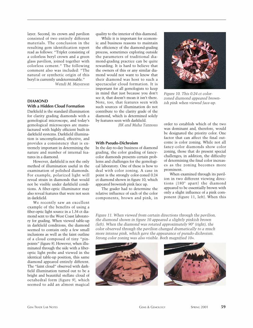
layer. Second, its crown and pavilionconsisted of two entirely differentmaterials. The conclusion in theresulting gem identification reportread as follows: “Triplet consisting ofa colorless beryl crown and a greenglass pavilion, joined together withcolorless cement.” The followingcomment also was included: “Thenatural or synthetic origin of thisberyl is currently undeterminable.”
Wendi M. Mayerson
DIAMONDWith a Hidden Cloud FormationDarkfield is the standard illuminationfor clarity grading diamonds with agemological microscope, and today’sgemological microscopes are manu-factured with highly efficient built-indarkfield systems. Darkfield illumina-tion is uncomplicated, effective, andprovides a consistency that is ex-tremely important in determining thenature and number of internal fea-tures in a diamond.
However, darkfield is not the onlymethod of illumination useful in theexamination of polished diamonds.For example, polarized light willreveal strain in diamonds that wouldnot be visible under darkfield condi-tions. A fiber-optic illuminator mayalso reveal features that were not seenin darkfield.
We recently saw an excellentexample of the benefits of using afiber-optic light source in a 1.34 ct dia-mond sent to the West Coast laborato-ry for grading. When viewed table-upin darkfield conditions, the diamondseemed to contain only a few smallinclusions as well as the faint outlineof a cloud composed of tiny “pin-points” (figure 8). However, when illu-minated through the side with a fiber-optic light probe and viewed in theidentical table-up position, this samediamond appeared entirely different.The “faint cloud” observed with dark-field illumination turned out to be abright and beautiful stellate cloud ofoctahedral form (figure 9), whichseemed to add an almost magical
quality to the interior of this diamond.While it is important for econom-
ic and business reasons to maintainthe efficiency of the diamond-gradingprocess, sometimes exploring outsidethe parameters of traditional dia-mond-grading practice can be quiterewarding. It is hard to believe thatthe owners of this or any similar dia-mond would not want to know thattheir diamond was host to such aspectacular cloud formation. It isimportant for all gemologists to keepin mind that just because you don’tsee it, that doesn’t mean it isn’t there.Note, too, that features seen withsuch sources of illumination do notcontribute to the clarity grade of thediamond, which is determined solelyby features seen with darkfield.
JIK and Maha Tannous
With Pseudo-DichroismIn the day-to-day business of diamondgrading, the color grading of fancy-color diamonds presents certain prob-lems and challenges for the gemologi-cal laboratory. One of these is how todeal with color zoning. A case inpoint is the strongly color-zoned 0.24ct diamond shown in figure 10, whichappeared brownish pink face up.
The grader had to determine therelative influence of each of the colorcomponents, brown and pink, in
order to establish which of the twowas dominant and, therefore, wouldbe designated the priority color. Onefactor that can affect the final out-come is color zoning. While not allfancy-color diamonds show colorzoning, those that do present specialchallenges; in addition, the difficultyof determining the final color increas-es as the zoning becomes moreprominent.
When examined through its pavil-ion in two different viewing direc-tions (180° apart) the diamondappeared to be essentially brown withonly a slight influence of a pink com-ponent (figure 11, left). When this
GEM TRADE LAB NOTES GEMS & GEMOLOGY SPRING 2001 59
Figure 10. This 0.24 ct color-zoned diamond appeared brown-ish pink when viewed face-up.
Figure 11. When viewed from certain directions through the pavilion,the diamond shown in figure 10 appeared a slightly pinkish brown(left). When the diamond was rotated approximately 90° (right), thecolor observed through the pavilion changed dramatically to a muchmore intense pink, which gave the appearance of pseudo-dichroism.Strong color zoning was also visible. Both magnified 10×.
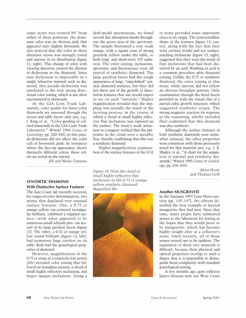
60 GEM TRADE LAB NOTES GEMS & GEMOLOGY Spring 2001
same stone was rotated 90° fromeither of these positions, the domi-nant color was an obvious pink thatappeared only slightly brownish. Wealso noticed that the color in thesealternate views was strongly zonedand uneven in its distribution (figure11, right). This change of color withviewing direction created the illusionof dichroism in the diamond. Sincetrue dichroism is impossible in asingly refractive mineral such as dia-mond, this pseudo-dichroism wasattributed to the very strong direc-tional color zoning, which is not oftenencountered in diamonds.
At the GIA Gem Trade Lab-oratory, color grades for fancy-colordiamonds are assessed through thecrown and table facets only (see, e.g.,J. King et al., “Color grading of col-ored diamonds in the GIA Gem TradeLaboratory,” Winter 1994 Gems &Gemology, pp. 220–242), so this pseu-do-dichroism did not affect the colorcall of brownish pink. In instanceswhere the face-up appearance showsdistinctly different colors, those col-ors are noted on the reports.
JIK and Maha Tannous
SYNTHETIC DIAMONDWith Distinctive Surface FeaturesThe East Coast lab recently received,for origin-of-color determination, twostones that displayed very unusualsurface features. One, a 0.75 ctorange-yellow cut-cornered rectangu-lar brilliant, exhibited a stippled sur-face—with what appeared to benumerous small whitish pits—on sev-eral of its large pavilion facets (figure12). The other, a 0.52 ct orangy yel-low round brilliant (figure 13, left),had numerous large cavities on itstable. Both had the gemological prop-erties of diamond.
However, magnification of the0.75 ct stone at a relatively low power(10×) revealed color zoning that fol-lowed an hourglass pattern, a cloud ofsmall highly reflective inclusions, andlarger opaque inclusions. Using a
desk-model spectroscope, we foundseveral fine absorption bands through-out the green area of the spectrum.The sample fluoresced a very weakorange, with a square zone of stronggreenish yellow under the table, toboth long- and short-wave UV radia-tion. The color zoning, inclusions,spectrum, and fluorescence were alltypical of synthetic diamond. Thelarge pavilion facets had the roughappearance of large, “unpolished” nat-ural diamond surfaces, but they didnot show any of the growth or disso-lution features that one would expectto see on such “naturals.” Highermagnification revealed that the stip-pling was actually the result of thefaceting process, in the course ofwhich a cloud of small highly reflec-tive flux inclusions was exposed onthe surface. The stone’s weak attrac-tion to a magnet verified that the pin-points in the cloud were a metallicflux, thereby confirming that this wasa synthetic diamond.
Higher-magnification examina-tion of the surface features of the 0.52
ct stone provided some importantclues to its origin. The noncrystallineshape of the features (figure 13, cen-ter), along with the fact that theywere cavities (voids) and not surface-reaching inclusions (figure 13, right),suggested that they were the result offlux inclusions that had been dis-solved by an acid. Washing in acid isa common procedure after diamondcutting. Unlike the 0.75 ct syntheticdiamond, the color zoning in thisstone, while uneven, did not followan obvious hourglass pattern. Onlyexamination through the bezel facetsprovided us with the visual clue of apartial cubic growth structure, whichsuggested synthetic origin. Thestrong magnetic reaction (in responseto the remaining, wholly includedflux) confirmed that this diamondwas also synthetic.
Although the surface features ofboth synthetic diamonds were some-what unusual, the other propertieswere consistent with those previouslynoted for this material (see, e.g., J. E.Shigley et al., “A chart for the separa-tion of natural and synthetic dia-monds,” Winter 1995 Gems & Gemol-ogy, pp. 256–265).
Akira Hyatt and Thomas Gelb
Another MUSGRAVITEIn the Summer 1997 Gem News sec-tion (pp. 145–147), the editors de-scribed the first example of facetedmusgravite they had seen. Since thattime, many people have submittedstones to the laboratory for testing inthe hopes that they would prove tobe musgravite, which has becomehighly sought after as a collector’sstone. Until recently, all of thosestones turned out to be taaffeite. Theseparation of these two minerals isdifficult, because their physical andoptical properties overlap to such adegree that it is impossible to distin-guish them completely with standardgemological testing.
A few months ago, gem collectorJames Houran sent our West Coast
Figure 12. Note the cloud ofsmall highly reflective fluxinclusions in this 0.75 ct orange-yellow synthetic diamond.Magnified 30×.
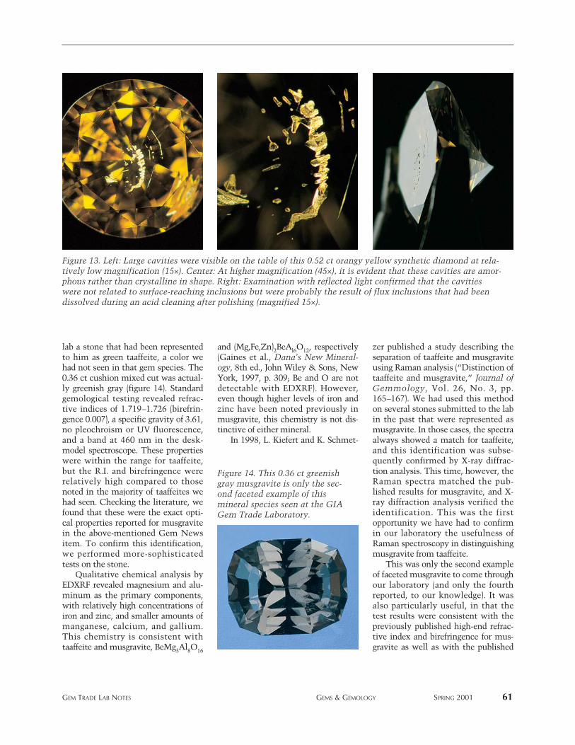
lab a stone that had been representedto him as green taaffeite, a color wehad not seen in that gem species. The0.36 ct cushion mixed cut was actual-ly greenish gray (figure 14). Standardgemological testing revealed refrac-tive indices of 1.719–1.726 (birefrin-gence 0.007), a specific gravity of 3.61,no pleochroism or UV fluorescence,and a band at 460 nm in the desk-model spectroscope. These propertieswere within the range for taaffeite,but the R.I. and birefringence wererelatively high compared to thosenoted in the majority of taaffeites wehad seen. Checking the literature, wefound that these were the exact opti-cal properties reported for musgravitein the above-mentioned Gem Newsitem. To confirm this identification,we performed more-sophisticatedtests on the stone.
Qualitative chemical analysis byEDXRF revealed magnesium and alu-minum as the primary components,with relatively high concentrations ofiron and zinc, and smaller amounts ofmanganese, calcium, and gallium.This chemistry is consistent withtaaffeite and musgravite, BeMg3Al8O16
and (Mg,Fe,Zn)2BeAl6O12, respectively(Gaines et al., Dana’s New Mineral-ogy, 8th ed., John Wiley & Sons, NewYork, 1997, p. 309; Be and O are notdetectable with EDXRF). However,even though higher levels of iron andzinc have been noted previously inmusgravite, this chemistry is not dis-tinctive of either mineral.
In 1998, L. Kiefert and K. Schmet-
zer published a study describing theseparation of taaffeite and musgraviteusing Raman analysis (“Distinction oftaaffeite and musgravite,” Journal ofGemmology, Vol. 26, No. 3, pp.165–167). We had used this methodon several stones submitted to the labin the past that were represented asmusgravite. In those cases, the spectraalways showed a match for taaffeite,and this identification was subse-quently confirmed by X-ray diffrac-tion analysis. This time, however, theRaman spectra matched the pub-lished results for musgravite, and X-ray diffraction analysis verified theidentification. This was the firstopportunity we have had to confirmin our laboratory the usefulness ofRaman spectroscopy in distinguishingmusgravite from taaffeite.
This was only the second exampleof faceted musgravite to come throughour laboratory (and only the fourthreported, to our knowledge). It wasalso particularly useful, in that thetest results were consistent with thepreviously published high-end refrac-tive index and birefringence for mus-gravite as well as with the published
GEM TRADE LAB NOTES GEMS & GEMOLOGY SPRING 2001 61
Figure 13. Left: Large cavities were visible on the table of this 0.52 ct orangy yellow synthetic diamond at rela-tively low magnification (15×). Center: At higher magnification (45×), it is evident that these cavities are amor-phous rather than crystalline in shape. Right: Examination with reflected light confirmed that the cavitieswere not related to surface-reaching inclusions but were probably the result of flux inclusions that had beendissolved during an acid cleaning after polishing (magnified 15×).
Figure 14. This 0.36 ct greenishgray musgravite is only the sec-ond faceted example of thismineral species seen at the GIAGem Trade Laboratory.
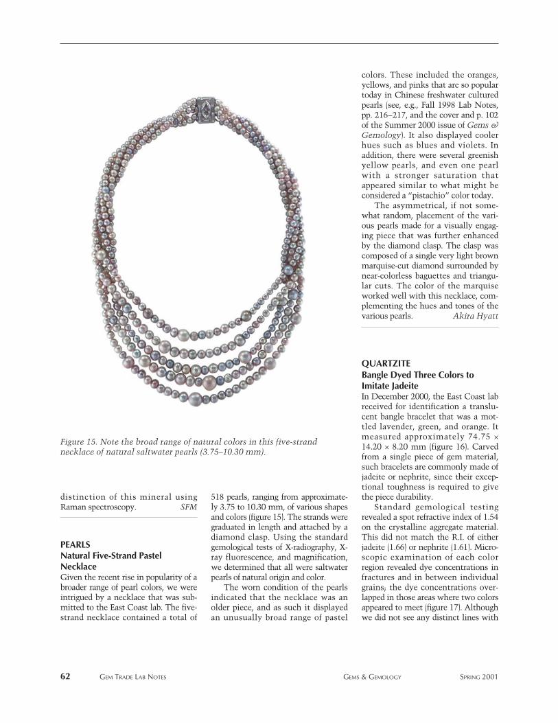
distinction of this mineral usingRaman spectroscopy. SFM
PEARLS Natural Five-Strand PastelNecklace Given the recent rise in popularity of abroader range of pearl colors, we wereintrigued by a necklace that was sub-mitted to the East Coast lab. The five-strand necklace contained a total of
518 pearls, ranging from approximate-ly 3.75 to 10.30 mm, of various shapesand colors (figure 15). The strands weregraduated in length and attached by adiamond clasp. Using the standardgemological tests of X-radiography, X-ray fluorescence, and magnification,we determined that all were saltwaterpearls of natural origin and color.
The worn condition of the pearlsindicated that the necklace was anolder piece, and as such it displayedan unusually broad range of pastel
colors. These included the oranges,yellows, and pinks that are so populartoday in Chinese freshwater culturedpearls (see, e.g., Fall 1998 Lab Notes,pp. 216–217, and the cover and p. 102of the Summer 2000 issue of Gems &Gemology). It also displayed coolerhues such as blues and violets. Inaddition, there were several greenishyellow pearls, and even one pearlwith a stronger saturation thatappeared similar to what might beconsidered a “pistachio” color today.
The asymmetrical, if not some-what random, placement of the vari-ous pearls made for a visually engag-ing piece that was further enhancedby the diamond clasp. The clasp wascomposed of a single very light brownmarquise-cut diamond surrounded bynear-colorless baguettes and triangu-lar cuts. The color of the marquiseworked well with this necklace, com-plementing the hues and tones of thevarious pearls. Akira Hyatt
QUARTZITE Bangle Dyed Three Colors toImitate JadeiteIn December 2000, the East Coast labreceived for identification a translu-cent bangle bracelet that was a mot-tled lavender, green, and orange. Itmeasured approximately 74.75 ×14.20 × 8.20 mm (figure 16). Carvedfrom a single piece of gem material,such bracelets are commonly made ofjadeite or nephrite, since their excep-tional toughness is required to givethe piece durability.
Standard gemological testingrevealed a spot refractive index of 1.54on the crystalline aggregate material.This did not match the R.I. of eitherjadeite (1.66) or nephrite (1.61). Micro-scopic examination of each colorregion revealed dye concentrations infractures and in between individualgrains; the dye concentrations over-lapped in those areas where two colorsappeared to meet (figure 17). Althoughwe did not see any distinct lines with
62 GEM TRADE LAB NOTES GEMS & GEMOLOGY SPRING 2001
Figure 15. Note the broad range of natural colors in this five-strandnecklace of natural saltwater pearls (3.75–10.30 mm).
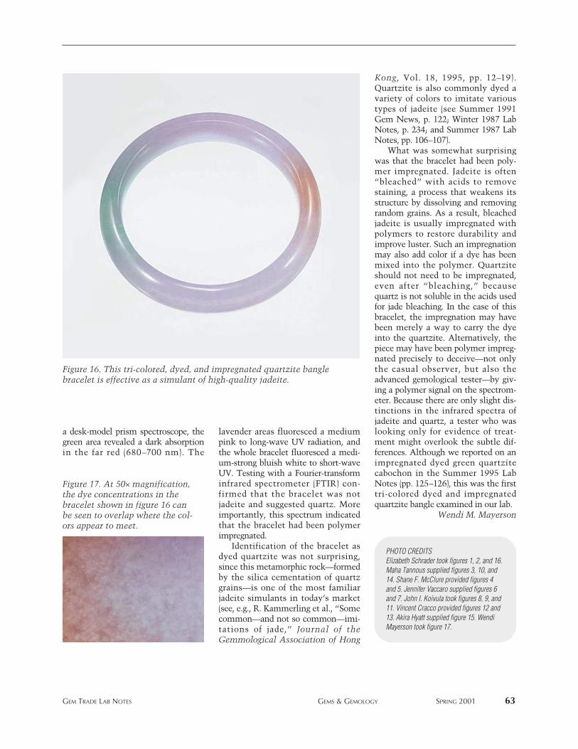
a desk-model prism spectroscope, thegreen area revealed a dark absorptionin the far red (680–700 nm). The
lavender areas fluoresced a mediumpink to long-wave UV radiation, andthe whole bracelet fluoresced a medi-um-strong bluish white to short-waveUV. Testing with a Fourier-transforminfrared spectrometer (FTIR) con-firmed that the bracelet was notjadeite and suggested quartz. Moreimportantly, this spectrum indicatedthat the bracelet had been polymerimpregnated.
Identification of the bracelet asdyed quartzite was not surprising,since this metamorphic rock—formedby the silica cementation of quartzgrains—is one of the most familiarjadeite simulants in today’s market(see, e.g., R. Kammerling et al., “Somecommon—and not so common—imi-tations of jade,” Journal of theGemmological Association of Hong
Kong, Vol. 18, 1995, pp. 12–19).Quartzite is also commonly dyed avariety of colors to imitate varioustypes of jadeite (see Summer 1991Gem News, p. 122; Winter 1987 LabNotes, p. 234; and Summer 1987 LabNotes, pp. 106–107).
What was somewhat surprisingwas that the bracelet had been poly-mer impregnated. Jadeite is often“bleached” with acids to removestaining, a process that weakens itsstructure by dissolving and removingrandom grains. As a result, bleachedjadeite is usually impregnated withpolymers to restore durability andimprove luster. Such an impregnationmay also add color if a dye has beenmixed into the polymer. Quartziteshould not need to be impregnated,even after “bleaching,” becausequartz is not soluble in the acids usedfor jade bleaching. In the case of thisbracelet, the impregnation may havebeen merely a way to carry the dyeinto the quartzite. Alternatively, thepiece may have been polymer impreg-nated precisely to deceive—not onlythe casual observer, but also theadvanced gemological tester—by giv-ing a polymer signal on the spectrom-eter. Because there are only slight dis-tinctions in the infrared spectra ofjadeite and quartz, a tester who waslooking only for evidence of treat-ment might overlook the subtle dif-ferences. Although we reported on animpregnated dyed green quartzitecabochon in the Summer 1995 LabNotes (pp. 125–126), this was the firsttri-colored dyed and impregnatedquartzite bangle examined in our lab.
Wendi M. Mayerson
GEM TRADE LAB NOTES GEMS & GEMOLOGY SPRING 2001 63
Figure 16. This tri-colored, dyed, and impregnated quartzite banglebracelet is effective as a simulant of high-quality jadeite.
Figure 17. At 50× magnification,the dye concentrations in thebracelet shown in figure 16 canbe seen to overlap where the col-ors appear to meet.
PHOTO CREDITSElizabeth Schrader took figures 1, 2, and 16.Maha Tannous supplied figures 3, 10, and14. Shane F. McClure provided figures 4and 5. Jennifer Vaccaro supplied figures 6and 7. John I. Koivula took figures 8, 9, and11. Vincent Cracco provided figures 12 and13. Akira Hyatt supplied figure 15. WendiMayerson took figure 17.
64 GEM NEWS INTERNATIONAL GEMS & GEMOLOGY SPRING 2001
his issue marks the introduction of the Gem NewsInternational (GNI) section in Gems & Gemology.
We have restructured the Gem News section as GNI totruly reflect the international nature of our discipline.This section will provide a forum for brief communica-tions and specific coverage of new localities, new materi-als, and new techniques/instrumentation, as well as theconference reports and many other interesting develop-ments that our readers have come to anticipate. The edi-torship of GNI has been assumed by Brendan Laurs,senior editor of Gems & Gemology. In addition, we haveadded three more contributing editors from the world’smajor gemological laboratories.
As before, items from other contributors are welcome.Author bylines are provided for contributing editors andoutside authors (with affiliation and e-mail, where avail-able, on the first entry if more than one entry is provided).Items without bylines were prepared by the section editoror other G&G staff. All contributions should be sent toBrendan Laurs at [email protected] (e-mail), 760-603-4595(fax), or GIA, 5345 Armada Drive, Carlsbad, CA 92008.
DIAMONDSWhite House Conference on “Conflict” Diamonds. In aneffort to ensure political stability and eliminate humanrights abuses in certain African countries, the outgoingU.S. Presidential administration convened the “WhiteHouse Diamond Conference: Technologies for Identi-fication and Certification” in Washington, D.C., onJanuary 10. This one-day conference addressed the need toeliminate conflict diamonds (e.g., those mined from rebel-controlled areas in Angola, the Democratic Republic ofthe Congo, and Sierra Leone) from international com-merce. The objective was to determine if technology is inplace—or could be developed and perfected within thenext five to 10 years—to identify or track rough and pol-ished diamonds from specific regions of origin throughthe jewelry trade to the consumer. This goal should beaccomplished without disrupting or penalizing the legiti-
mate diamond trade, including the economies of Africancountries that depend on legitimate diamond exports,such as Botswana, Namibia, and South Africa. Accordingto current estimates, conflict diamonds account for lessthan 4% of the world’s rough diamond production.
The conference brought together 132 participants fromgovernments, the diamond industry, companies with spe-cialized technologies, academia (including museums), andhumanitarian nongovernmental organizations (e.g., GlobalWitness, Amnesty International). Most of the participantswere policy makers, scientists, and engineers from theU.S. Also present were technical personnel from Canada,Great Britain, Belgium, and Israel, as well as diplomaticrepresentatives of countries involved in the diamond trade.
A plenary “background” session explained the complex-ities of the diamond industry to conference participantswho were not involved in the trade. Recurrent themes were:
• The long-term harm that negative publicity associatedwith conflict diamonds could cause the jewelry industry
• The recognition that, with the knowledge presentlyavailable, it is not possible to certify the country of ori-gin of individual diamonds, either rough or polished
• The difficulty of completely eliminating trade in con-flict diamonds in impoverished societies where corrup-tion exists.
The World Diamond Council (represented by EliIzhakoff) strongly supports a global rough-diamond certifica-tion program, such as the proposed “System forInternational Rough Diamond Export and ImportControls,” as the only feasible approach to the conflict dia-mond problem at this time (to view a copy of the document,visit www.worlddiamondcouncil.com). Yet the intricaciesof the diamond “pipeline” (described by Jeffrey Fischer ofthe Diamond Manufacturers and Importers Association ofAmerica), in which diamonds mined in 22 countries often
EDITORBrendan M. Laurs ([email protected])
CONTRIBUTING EDITORSEmmanuel Fritsch, IMN, University ofNantes, FranceHenry A. Hanni, SSEF, Basel, SwitzerlandKenneth Scarratt, AGTA Gemological TestingCenter, New YorkKarl Schmetzer, Petershausen, GermanyJames E. Shigley, GIA Research, Carlsbad,CaliforniaChristopher P. Smith, Gübelin Gem Lab,Lucerne, Switzerland
GEM NEWS International
T
GEMS & GEMOLOGY, Vol. 37, No. 1, pp. 64–78© 2001 Gemological Institute of America
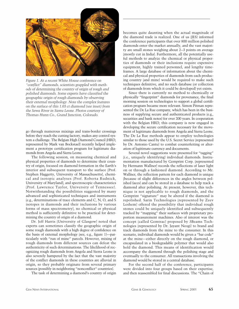
GEM NEWS INTERNATIONAL GEMS & GEMOLOGY SPRING 2001 65
go through numerous mixings and trans-border crossingsbefore they reach the cutting factory, makes any control sys-tem a challenge. The Belgian High Diamond Council (HRD,represented by Mark van Bockstael) recently helped imple-ment a prototype certification program for legitimate dia-monds from Angola and Sierra Leone.
The following session, on measuring chemical andphysical properties of diamonds to determine their coun-try of origin, focused on diamond formation in the Earth’sinterior and subsequent transport to the surface (Prof.Stephen Haggerty, University of Massachusetts), chemi-cal and isotopic analyses (Prof. Roberta Rudnick,University of Maryland), and spectroscopic characteristics(Prof. Lawrence Taylor, University of Tennessee).Notwithstanding the possibilities suggested by manyadvanced and sophisticated techniques and instruments(e.g., determinations of trace elements and C, N, O, and Sisotopes in diamonds and their inclusions by variousforms of mass spectrometry), no chemical or physicalmethod is sufficiently definitive to be practical for deter-mining the country of origin of a diamond.
Dr. Jeff Harris (University of Glasgow) noted thatexperts can sometimes classify the geographic origin ofsome rough diamonds with a high degree of confidence onthe basis of external morphology (see, e.g., figure 1)—par-ticularly with “run of mine” parcels. However, mixing ofrough diamonds from different sources can defeat theauthenticity of such determinations. The likelihood of rec-ognizing rough diamonds from Angola and Sierra Leone isalso severely hampered by the fact that the vast majorityof the conflict diamonds in these countries are alluvial inorigin, so they probably originate from several primarysources (possibly in neighboring “nonconflict“ countries).
The task of determining a diamond’s country of origin
becomes quite daunting when the actual magnitude ofthe diamond trade is realized. One of us (JES) informedthe conference participants that over 800 million polisheddiamonds enter the market annually, and the vast majori-ty are small stones weighing about 2–3 points on average(mostly cut in India). Furthermore, all the potentially use-ful methods to analyze the chemical or physical proper-ties of diamonds or their inclusions require expensiveequipment, highly trained personnel, and lengthy time-frames. A large database of information about the chemi-cal and physical properties of diamonds from each produc-ing country (and mine) would be required to make suchtechniques definitive, and no such database (or collectionof diamonds from which it could be developed) yet exists.
Since there is currently no method to chemically orphysically “fingerprint” diamonds for provenance, the finalmorning session on technologies to support a global certifi-cation program became more relevant. Simon Pitman repre-sented the De La Rue company, which has been in the busi-ness of supplying secure and authenticated products (e.g.,securities and bank notes) for over 200 years. In cooperationwith the Belgian HRD, this company is now engaged indeveloping the secure certification necessary for the move-ment of legitimate diamonds from Angola and Sierra Leone.The De La Rue methods appear to employ technologiessimilar to those used by the U.S. Secret Service (representedby Dr. Antonio Cantu) to combat counterfeiting or alter-ation of legitimate currency and documents.
Several novel suggestions were presented for “tagging”(i.e., uniquely identifying) individual diamonds. Instru-mentation manufactured by Gemprint Corp. (representedby Hermann Wallner) records the reflections of laser lighton or through a fashioned diamond. According to Mr.Wallner, the reflection pattern for each diamond is unique(because of slight differences in the angles between pol-ished faces) and can be stored in a database to help track adiamond after polishing. At present, however, this tech-nique is not applicable to rough diamonds, and theGemprint “signature” may be altered if the diamond isrepolished. Sarin Technologies (represented by ZeevLeshem) offered the possibility that individual roughstones could be uniquely identified and subsequentlytracked by “mapping” their surfaces with proprietary pro-portion measurement machines. Also of interest was theconcept (called Gemtrac) proposed by 3Beams Tech-nologies (represented by Dr. Jayant Neogi) to brand andtrack diamonds from the mine to the consumer. In thisscenario, individual diamonds would be given a “bar code”at the mine—either directly on the rough diamond, orencapsulated in a biodegradable polymer that would alsohold the diamond. This means of identification wouldaccompany the diamond through the polishing stage andeventually to the consumer. All transactions involving thediamond would be stored in a central database.
For the second half of the conference, participantswere divided into four groups based on their expertise,and then reassembled for final discussions. The “Chain of
Figure 1. At a recent White House conference on“conflict” diamonds, scientists grappled with meth-ods of determining the country of origin of rough andpolished diamonds. Some experts have classified thegeographic origin of rough diamonds by observingtheir external morphology. Note the complex featureson the surface of this 1.03 ct diamond (see inset) fromthe Sewa River in Sierra Leone. Photos courtesy ofThomas Hunn Co., Grand Junction, Colorado.
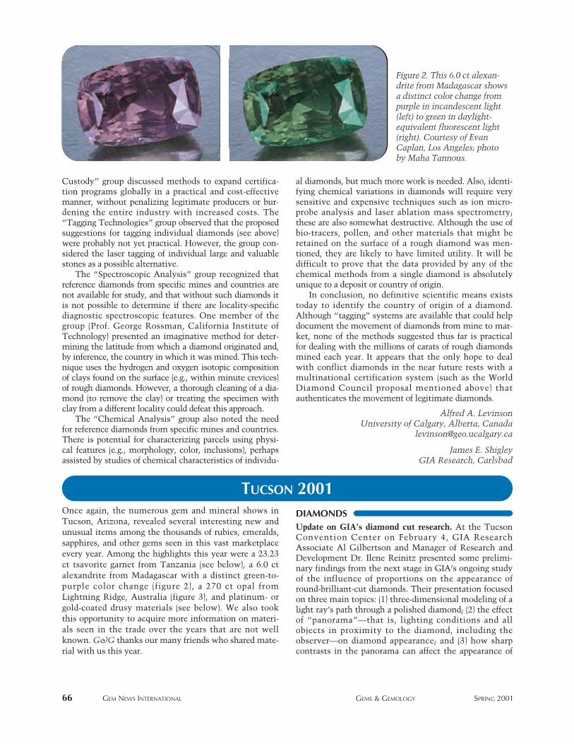
TUCSON 2001
Custody” group discussed methods to expand certifica-tion programs globally in a practical and cost-effectivemanner, without penalizing legitimate producers or bur-dening the entire industry with increased costs. The“Tagging Technologies” group observed that the proposedsuggestions for tagging individual diamonds (see above)were probably not yet practical. However, the group con-sidered the laser tagging of individual large and valuablestones as a possible alternative.
The “Spectroscopic Analysis” group recognized thatreference diamonds from specific mines and countries arenot available for study, and that without such diamonds itis not possible to determine if there are locality-specificdiagnostic spectroscopic features. One member of thegroup (Prof. George Rossman, California Institute ofTechnology) presented an imaginative method for deter-mining the latitude from which a diamond originated and,by inference, the country in which it was mined. This tech-nique uses the hydrogen and oxygen isotopic compositionof clays found on the surface (e.g., within minute crevices)of rough diamonds. However, a thorough cleaning of a dia-mond (to remove the clay) or treating the specimen withclay from a different locality could defeat this approach.
The “Chemical Analysis” group also noted the needfor reference diamonds from specific mines and countries.There is potential for characterizing parcels using physi-cal features (e.g., morphology, color, inclusions), perhapsassisted by studies of chemical characteristics of individu-
al diamonds, but much more work is needed. Also, identi-fying chemical variations in diamonds will require verysensitive and expensive techniques such as ion micro-probe analysis and laser ablation mass spectrometry;these are also somewhat destructive. Although the use ofbio-tracers, pollen, and other materials that might beretained on the surface of a rough diamond was men-tioned, they are likely to have limited utility. It will bedifficult to prove that the data provided by any of thechemical methods from a single diamond is absolutelyunique to a deposit or country of origin.
In conclusion, no definitive scientific means existstoday to identify the country of origin of a diamond.Although “tagging” systems are available that could helpdocument the movement of diamonds from mine to mar-ket, none of the methods suggested thus far is practicalfor dealing with the millions of carats of rough diamondsmined each year. It appears that the only hope to dealwith conflict diamonds in the near future rests with amultinational certification system (such as the WorldDiamond Council proposal mentioned above) thatauthenticates the movement of legitimate diamonds.
Alfred A. LevinsonUniversity of Calgary, Alberta, Canada
James E. ShigleyGIA Research, Carlsbad
66 GEM NEWS INTERNATIONAL GEMS & GEMOLOGY SPRING 2001
Figure 2. This 6.0 ct alexan-drite fromMadagascar showsa distinct color change frompurple in incandescent light(left) to green in daylight-equivalent fluorescent light(right). Courtesy of EvanCaplan, Los Angeles; photoby Maha Tannous.
Once again, the numerous gem and mineral shows inTucson, Arizona, revealed several interesting new andunusual items among the thousands of rubies, emeralds,sapphires, and other gems seen in this vast marketplaceevery year. Among the highlights this year were a 23.23ct tsavorite garnet from Tanzania (see below), a 6.0 ctalexandrite from Madagascar with a distinct green-to-purple color change (figure 2), a 270 ct opal fromLightning Ridge, Australia (figure 3), and platinum- orgold-coated drusy materials (see below). We also tookthis opportunity to acquire more information on materi-als seen in the trade over the years that are not wellknown. G&G thanks our many friends who shared mate-rial with us this year.
DIAMONDSUpdate on GIA’s diamond cut research. At the TucsonConvention Center on February 4, GIA ResearchAssociate Al Gilbertson and Manager of Research andDevelopment Dr. Ilene Reinitz presented some prelimi-nary findings from the next stage in GIA’s ongoing studyof the influence of proportions on the appearance ofround-brilliant-cut diamonds. Their presentation focusedon three main topics: (1) three-dimensional modeling of alight ray’s path through a polished diamond; (2) the effectof “panorama”—that is, lighting conditions and allobjects in proximity to the diamond, including theobserver—on diamond appearance; and (3) how sharpcontrasts in the panorama can affect the appearance of
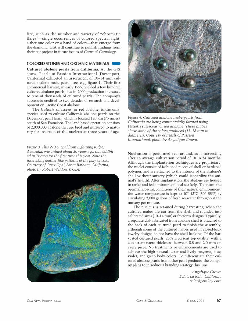
fire, such as the number and variety of “chromaticflares”—single occurrences of colored spectral light,either one color or a band of colors—that emerge fromthe diamond. GIA will continue to publish findings fromtheir cut project in future issues of Gems & Gemology.
COLORED STONES AND ORGANIC MATERIALSCultured abalone pearls from California. At the GJXshow, Pearls of Passion International (Davenport,California) exhibited an assortment of 10–14 mm cul-tured abalone mabe pearls (see, e.g., figure 4). Their firstcommercial harvest, in early 1999, yielded a few hundredcultured abalone pearls, but in 2000 production increasedto tens of thousands of cultured pearls. The company’ssuccess is credited to two decades of research and devel-opment on Pacific Coast abalone.
The Haliotis rufescens, or red abalone, is the onlyspecies used to culture California abalone pearls on theDavenport pearl farm, which is located 120 km (75 miles)south of San Francisco. The land-based operation consistsof 2,000,000 abalone that are bred and nurtured to matu-rity for insertion of the nucleus at three years of age.
Nucleation is performed year-around, as is harvestingafter an average cultivation period of 18 to 24 months.Although the implantation techniques are proprietary,the nuclei consist of fashioned pieces of shell or hardenedpolymer, and are attached to the interior of the abalone’sshell without surgery (which could jeopardize the ani-mal’s health). After implantation, the abalone are housedin tanks and fed a mixture of local sea kelp. To ensure theoptimal growing conditions of their natural environment,the water temperature is kept at 10°–13°C (50°–55°F) bycirculating 2,000 gallons of fresh seawater throughout thenursery per minute.
The nucleus is retained during harvesting, when thecultured mabes are cut from the shell and rounded intocalibrated sizes (10–14 mm) or freeform designs. Typically,a separate disk fabricated from abalone shell is attached tothe back of each cultured pearl to finish the assembly,although some of the cultured mabes used in closed-backjewelry designs do not have the shell backing. Of the har-vested cultured pearls, 25% represent top quality, with aconsistent nacre thickness between 0.5 and 2.0 mm onevery piece. No treatments or enhancements are used toachieve the high natural luster and lively magenta, blue,violet, and green body colors. To differentiate their cul-tured abalone pearls from other pearl products, the compa-ny plans to introduce a branding strategy this June.
Angelique CrownEclat, La Jolla, California
GEM NEWS INTERNATIONAL GEMS & GEMOLOGY SPRING 2001 67
Figure 4. Cultured abalone mabe pearls fromCalifornia are being commercially farmed usingHaliotis rufescens, or red abalone. These mabesshow some of the colors produced (11–13 mm indiameter). Courtesy of Pearls of PassionInternational; photo by Angelique Crown.
Figure 3. This 270 ct opal from Lightning Ridge,Australia, was mined about 30 years ago, but exhibit-ed in Tucson for the first time this year. Note theinteresting feather-like patterns of the play-of-color.Courtesy of Opex Opal, Santa Barbara, California;photo by Robert Weldon, © GIA.
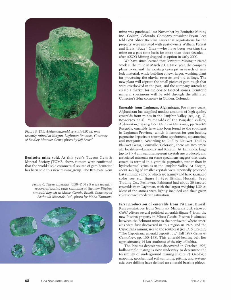
Benitoite mine sold. At this year’s Tucson Gem &Mineral Society (TGMS) show, rumors were confirmedthat the world’s sole commercial source of gem benitoitehas been sold to a new mining group. The Benitoite Gem
mine was purchased last November by Benitoite MiningInc., Golden, Colorado. Company president Bryan Leestold GNI editor Brendan Laurs that negotiations for theproperty were initiated with past-owners William Forrestand Elvis “Buzz” Gray—who have been working themine on a part-time basis for more than three decades—after AZCO Mining dropped its option in early 2000.
We have since learned that Benitoite Mining initiatedwork at the mine in March 2001. Next year, the companyplans to expand the existing open pit in search of newlode material, while building a new, larger, washing plantfor processing the eluvial reserves and old tailings. Thenew plant will capture the small pieces of gem rough thatwere overlooked in the past, and the company intends tocreate a market for melee-size faceted stones. Benitoitemineral specimens will be sold through the affiliatedCollector’s Edge company in Golden, Colorado.
Emeralds from Laghman, Afghanistan. For many years,Afghanistan has supplied modest amounts of high-qualityemeralds from mines in the Panjshir Valley (see, e.g., G.Bowersox et al., “Emeralds of the Panjshir Valley,Afghanistan,” Spring 1991 Gems & Gemology, pp. 26–39).Recently, emeralds have also been found to the southeastin Laghman Province, which is famous for gem-bearingpegmatite deposits of tourmaline, spodumene, aquamarine,and morganite. According to Dudley Blauwet (DudleyBlauwet Gems, Louisville, Colorado), there are two emer-ald localities—Lamonda and Korgun. At Lamonda, large(up to 3 × 4 cm) semitransparent crystals are produced, andassociated minerals on some specimens suggest that theseemeralds formed in a granitic pegmatite, rather than inhydrothermal veins as in the Panjshir Valley. At Korgun,about 4–5 kg of smaller crystals were reportedly producedlast summer, some of which are gemmy and have saturatedcolor (see, e.g., figure 5). Syed Iftikhar Hussain (SyedTrading Co., Peshawar, Pakistan) had about 25 facetedemeralds from Laghman, with the largest weighing 1.39 ct.Most of the stones were lightly included and their greencolor showed moderate saturation.
First production of emeralds from Piteiras, Brazil.Representatives from Seahawk Minerals Ltd. showedG&G editors several polished emeralds (figure 6) from thenew Piteiras property in Minas Gerais. Piteiras is situatedbetween the Belmont mine to the northwest, where emer-alds were first discovered in this region in 1976, and theCapoeirana mining area to the southeast (see D. S. Epstein,“The Capoeirana emerald deposit . . .,” Fall 1989 Gems &Gemology, pp. 150–158). This emerald-bearing belt liesapproximately 14 km southeast of the city of Itabira.
The Piteiras deposit was discovered in October 1998;bulk-sample testing is now underway to determine thefeasibility of underground mining (figure 7). Geologicmapping, geochemical soil sampling, pitting, and system-atic core drilling have defined an emerald-bearing phlogo-
68 GEM NEWS INTERNATIONAL GEMS & GEMOLOGY SPRING 2001
Figure 5. This Afghan emerald crystal (4.02 ct) wasrecently mined at Korgun, Laghman Province. Courtesyof Dudley Blauwet Gems; photo by Jeff Scovil.
Figure 6. These emeralds (0.38–2.04 ct) were recentlyrecovered during bulk sampling at the new Piteiras
emerald deposit in Minas Gerais, Brazil. Courtesy ofSeahawk Minerals Ltd.; photo by Maha Tannous.
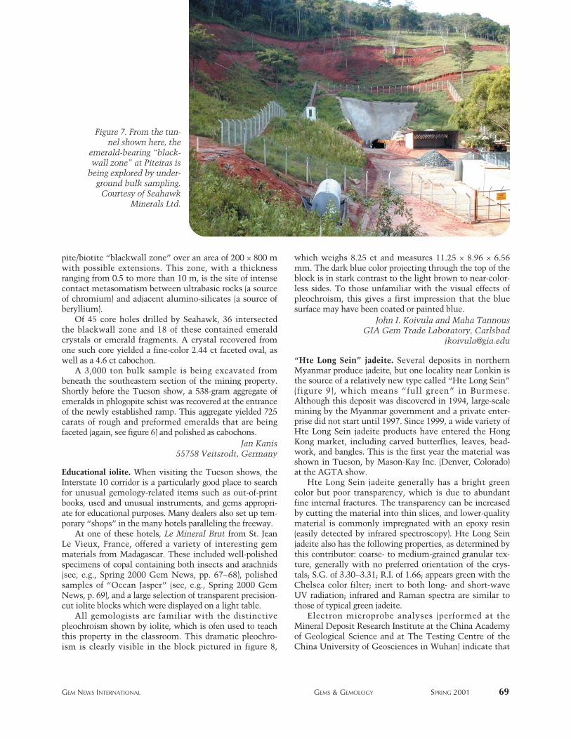
pite/biotite “blackwall zone” over an area of 200 × 800 mwith possible extensions. This zone, with a thicknessranging from 0.5 to more than 10 m, is the site of intensecontact metasomatism between ultrabasic rocks (a sourceof chromium) and adjacent alumino-silicates (a source ofberyllium).
Of 45 core holes drilled by Seahawk, 36 intersectedthe blackwall zone and 18 of these contained emeraldcrystals or emerald fragments. A crystal recovered fromone such core yielded a fine-color 2.44 ct faceted oval, aswell as a 4.6 ct cabochon.
A 3,000 ton bulk sample is being excavated frombeneath the southeastern section of the mining property.Shortly before the Tucson show, a 538-gram aggregate ofemeralds in phlogopite schist was recovered at the entranceof the newly established ramp. This aggregate yielded 725carats of rough and preformed emeralds that are beingfaceted (again, see figure 6) and polished as cabochons.
Jan Kanis 55758 Veitsrodt, Germany
Educational iolite. When visiting the Tucson shows, theInterstate 10 corridor is a particularly good place to searchfor unusual gemology-related items such as out-of-printbooks, used and unusual instruments, and gems appropri-ate for educational purposes. Many dealers also set up tem-porary “shops” in the many hotels paralleling the freeway.
At one of these hotels, Le Mineral Brut from St. JeanLe Vieux, France, offered a variety of interesting gemmaterials from Madagascar. These included well-polishedspecimens of copal containing both insects and arachnids(see, e.g., Spring 2000 Gem News, pp. 67–68), polishedsamples of “Ocean Jasper” (see, e.g., Spring 2000 GemNews, p. 69), and a large selection of transparent precision-cut iolite blocks which were displayed on a light table.
All gemologists are familiar with the distinctivepleochroism shown by iolite, which is ofen used to teachthis property in the classroom. This dramatic pleochro-ism is clearly visible in the block pictured in figure 8,
which weighs 8.25 ct and measures 11.25 × 8.96 × 6.56mm. The dark blue color projecting through the top of theblock is in stark contrast to the light brown to near-color-less sides. To those unfamiliar with the visual effects ofpleochroism, this gives a first impression that the bluesurface may have been coated or painted blue.
John I. Koivula and Maha TannousGIA Gem Trade Laboratory, Carlsbad
“Hte Long Sein” jadeite. Several deposits in northernMyanmar produce jadeite, but one locality near Lonkin isthe source of a relatively new type called “Hte Long Sein”(figure 9), which means “full green” in Burmese.Although this deposit was discovered in 1994, large-scalemining by the Myanmar government and a private enter-prise did not start until 1997. Since 1999, a wide variety ofHte Long Sein jadeite products have entered the HongKong market, including carved butterflies, leaves, bead-work, and bangles. This is the first year the material wasshown in Tucson, by Mason-Kay Inc. (Denver, Colorado)at the AGTA show.
Hte Long Sein jadeite generally has a bright greencolor but poor transparency, which is due to abundantfine internal fractures. The transparency can be increasedby cutting the material into thin slices, and lower-qualitymaterial is commonly impregnated with an epoxy resin(easily detected by infrared spectroscopy). Hte Long Seinjadeite also has the following properties, as determined bythis contributor: coarse- to medium-grained granular tex-ture, generally with no preferred orientation of the crys-tals; S.G. of 3.30–3.31; R.I. of 1.66; appears green with theChelsea color filter; inert to both long- and short-waveUV radiation; infrared and Raman spectra are similar tothose of typical green jadeite.
Electron microprobe analyses (performed at theMineral Deposit Research Institute at the China Academyof Geological Science and at The Testing Centre of theChina University of Geosciences in Wuhan) indicate that
GEM NEWS INTERNATIONAL GEMS & GEMOLOGY SPRING 2001 69
Figure 7. From the tun-nel shown here, the
emerald-bearing “black-wall zone” at Piteiras is
being explored by under-ground bulk sampling.
Courtesy of SeahawkMinerals Ltd.
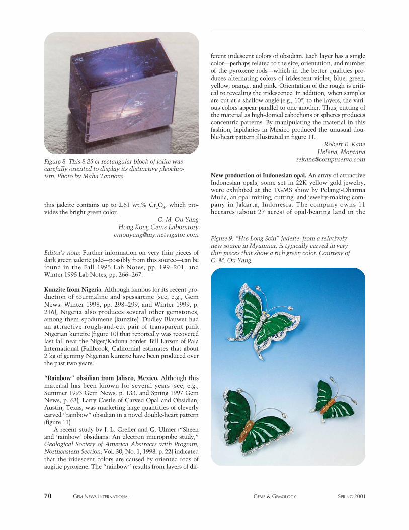
this jadeite contains up to 2.61 wt.% Cr2O3, which pro-vides the bright green color.
C. M. Ou YangHong Kong Gems Laboratory
Editor’s note: Further information on very thin pieces ofdark green jadeite jade—possibly from this source—can befound in the Fall 1995 Lab Notes, pp. 199–201, andWinter 1995 Lab Notes, pp. 266–267.
Kunzite from Nigeria. Although famous for its recent pro-duction of tourmaline and spessartine (see, e.g., GemNews: Winter 1998, pp. 298–299, and Winter 1999, p.216), Nigeria also produces several other gemstones,among them spodumene (kunzite). Dudley Blauwet hadan attractive rough-and-cut pair of transparent pinkNigerian kunzite (figure 10) that reportedly was recoveredlast fall near the Niger/Kaduna border. Bill Larson of PalaInternational (Fallbrook, California) estimates that about2 kg of gemmy Nigerian kunzite have been produced overthe past two years.
“Rainbow” obsidian from Jalisco, Mexico. Although thismaterial has been known for several years (see, e.g.,Summer 1993 Gem News, p. 133, and Spring 1997 GemNews, p. 63), Larry Castle of Carved Opal and Obsidian,Austin, Texas, was marketing large quantities of cleverlycarved “rainbow” obsidian in a novel double-heart pattern(figure 11).
A recent study by J. L. Greller and G. Ulmer (“Sheenand ‘rainbow’ obsidians: An electron microprobe study,”Geological Society of America Abstracts with Program,Northeastern Section, Vol. 30, No. 1, 1998, p. 22) indicatedthat the iridescent colors are caused by oriented rods ofaugitic pyroxene. The “rainbow” results from layers of dif-
ferent iridescent colors of obsidian. Each layer has a singlecolor—perhaps related to the size, orientation, and numberof the pyroxene rods—which in the better qualities pro-duces alternating colors of iridescent violet, blue, green,yellow, orange, and pink. Orientation of the rough is criti-cal to revealing the iridescence. In addition, when samplesare cut at a shallow angle (e.g., 10°) to the layers, the vari-ous colors appear parallel to one another. Thus, cutting ofthe material as high-domed cabochons or spheres producesconcentric patterns. By manipulating the material in thisfashion, lapidaries in Mexico produced the unusual dou-ble-heart pattern illustrated in figure 11.
Robert E. Kane Helena, Montana
New production of Indonesian opal. An array of attractiveIndonesian opals, some set in 22K yellow gold jewelry,were exhibited at the TGMS show by Pelangí-DharmaMulia, an opal mining, cutting, and jewelry-making com-pany in Jakarta, Indonesia. The company owns 11hectares (about 27 acres) of opal-bearing land in the
70 GEM NEWS INTERNATIONAL GEMS & GEMOLOGY SPRING 2001
Figure 9. “Hte Long Sein” jadeite, from a relativelynew source in Myanmar, is typically carved in verythin pieces that show a rich green color. Courtesy ofC. M. Ou Yang.
Figure 8. This 8.25 ct rectangular block of iolite wascarefully oriented to display its distinctive pleochro-ism. Photo by Maha Tannous.
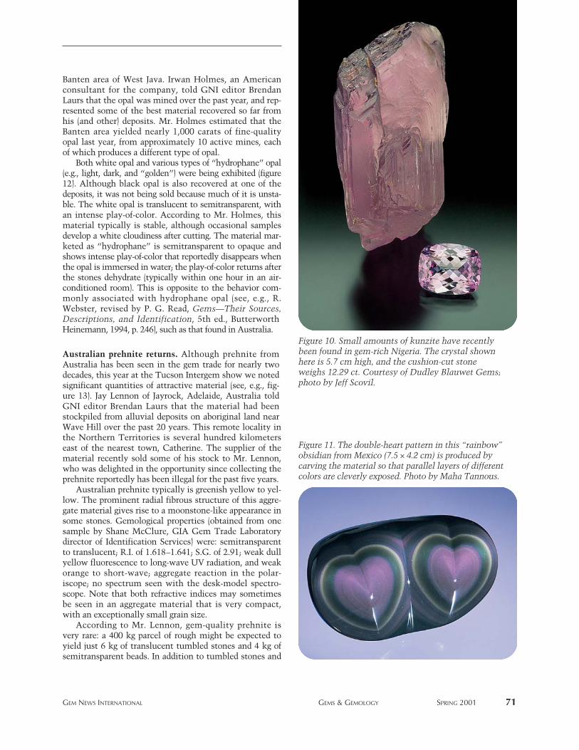
Banten area of West Java. Irwan Holmes, an Americanconsultant for the company, told GNI editor BrendanLaurs that the opal was mined over the past year, and rep-resented some of the best material recovered so far fromhis (and other) deposits. Mr. Holmes estimated that theBanten area yielded nearly 1,000 carats of fine-qualityopal last year, from approximately 10 active mines, eachof which produces a different type of opal.
Both white opal and various types of “hydrophane” opal(e.g., light, dark, and “golden”) were being exhibited (figure12). Although black opal is also recovered at one of thedeposits, it was not being sold because much of it is unsta-ble. The white opal is translucent to semitransparent, withan intense play-of-color. According to Mr. Holmes, thismaterial typically is stable, although occasional samplesdevelop a white cloudiness after cutting. The material mar-keted as “hydrophane” is semitransparent to opaque andshows intense play-of-color that reportedly disappears whenthe opal is immersed in water; the play-of-color returns afterthe stones dehydrate (typically within one hour in an air-conditioned room). This is opposite to the behavior com-monly associated with hydrophane opal (see, e.g., R.Webster, revised by P. G. Read, Gems—Their Sources,Descriptions, and Identification, 5th ed., ButterworthHeinemann, 1994, p. 246), such as that found in Australia.
Australian prehnite returns. Although prehnite fromAustralia has been seen in the gem trade for nearly twodecades, this year at the Tucson Intergem show we notedsignificant quantities of attractive material (see, e.g., fig-ure 13). Jay Lennon of Jayrock, Adelaide, Australia toldGNI editor Brendan Laurs that the material had beenstockpiled from alluvial deposits on aboriginal land nearWave Hill over the past 20 years. This remote locality inthe Northern Territories is several hundred kilometerseast of the nearest town, Catherine. The supplier of thematerial recently sold some of his stock to Mr. Lennon,who was delighted in the opportunity since collecting theprehnite reportedly has been illegal for the past five years.
Australian prehnite typically is greenish yellow to yel-low. The prominent radial fibrous structure of this aggre-gate material gives rise to a moonstone-like appearance insome stones. Gemological properties (obtained from onesample by Shane McClure, GIA Gem Trade Laboratorydirector of Identification Services) were: semitransparentto translucent; R.I. of 1.618–1.641; S.G. of 2.91; weak dullyellow fluorescence to long-wave UV radiation, and weakorange to short-wave; aggregate reaction in the polar-iscope; no spectrum seen with the desk-model spectro-scope. Note that both refractive indices may sometimesbe seen in an aggregate material that is very compact,with an exceptionally small grain size.
According to Mr. Lennon, gem-quality prehnite isvery rare: a 400 kg parcel of rough might be expected toyield just 6 kg of translucent tumbled stones and 4 kg ofsemitransparent beads. In addition to tumbled stones and
GEM NEWS INTERNATIONAL GEMS & GEMOLOGY SPRING 2001 71
Figure 11. The double-heart pattern in this “rainbow”obsidian from Mexico (7.5 × 4.2 cm) is produced bycarving the material so that parallel layers of differentcolors are cleverly exposed. Photo by Maha Tannous.
Figure 10. Small amounts of kunzite have recentlybeen found in gem-rich Nigeria. The crystal shownhere is 5.7 cm high, and the cushion-cut stoneweighs 12.29 ct. Courtesy of Dudley Blauwet Gems;photo by Jeff Scovil.
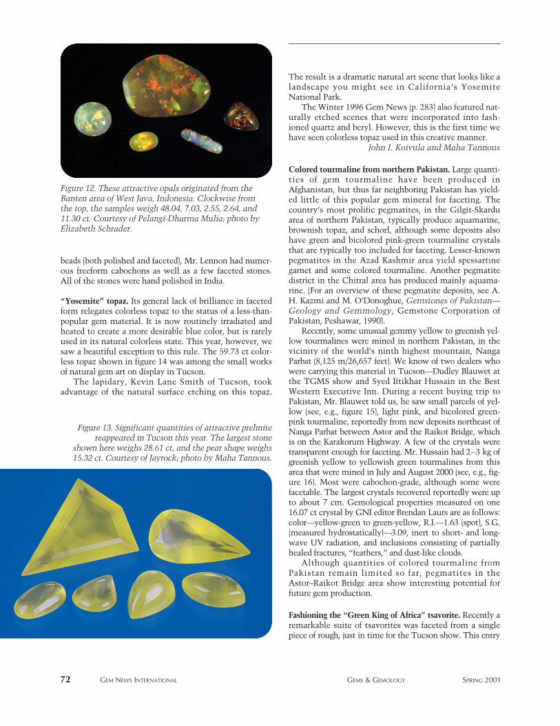
beads (both polished and faceted), Mr. Lennon had numer-ous freeform cabochons as well as a few faceted stones.All of the stones were hand polished in India.
“Yosemite” topaz. Its general lack of brilliance in facetedform relegates colorless topaz to the status of a less-than-popular gem material. It is now routinely irradiated andheated to create a more desirable blue color, but is rarelyused in its natural colorless state. This year, however, wesaw a beautiful exception to this rule. The 59.73 ct color-less topaz shown in figure 14 was among the small worksof natural gem art on display in Tucson.
The lapidary, Kevin Lane Smith of Tucson, tookadvantage of the natural surface etching on this topaz.
The result is a dramatic natural art scene that looks like alandscape you might see in California’s YosemiteNational Park.
The Winter 1996 Gem News (p. 283) also featured nat-urally etched scenes that were incorporated into fash-ioned quartz and beryl. However, this is the first time wehave seen colorless topaz used in this creative manner.
John I. Koivula and Maha Tannous
Colored tourmaline from northern Pakistan. Large quanti-ties of gem tourmaline have been produced inAfghanistan, but thus far neighboring Pakistan has yield-ed little of this popular gem mineral for faceting. Thecountry’s most prolific pegmatites, in the Gilgit-Skarduarea of northern Pakistan, typically produce aquamarine,brownish topaz, and schorl, although some deposits alsohave green and bicolored pink-green tourmaline crystalsthat are typically too included for faceting. Lesser-knownpegmatites in the Azad Kashmir area yield spessartinegarnet and some colored tourmaline. Another pegmatitedistrict in the Chitral area has produced mainly aquama-rine. (For an overview of these pegmatite deposits, see A.H. Kazmi and M. O’Donoghue, Gemstones of Pakistan—Geology and Gemmology, Gemstone Corporation ofPakistan, Peshawar, 1990).
Recently, some unusual gemmy yellow to greenish yel-low tourmalines were mined in northern Pakistan, in thevicinity of the world’s ninth highest mountain, NangaParbat (8,125 m/26,657 feet). We know of two dealers whowere carrying this material in Tucson—Dudley Blauwet atthe TGMS show and Syed Iftikhar Hussain in the BestWestern Executive Inn. During a recent buying trip toPakistan, Mr. Blauwet told us, he saw small parcels of yel-low (see, e.g., figure 15), light pink, and bicolored green-pink tourmaline, reportedly from new deposits northeast ofNanga Parbat between Astor and the Raikot Bridge, whichis on the Karakorum Highway. A few of the crystals weretransparent enough for faceting. Mr. Hussain had 2–3 kg ofgreenish yellow to yellowish green tourmalines from thisarea that were mined in July and August 2000 (see, e.g., fig-ure 16). Most were cabochon-grade, although some werefacetable. The largest crystals recovered reportedly were upto about 7 cm. Gemological properties measured on one16.07 ct crystal by GNI editor Brendan Laurs are as follows:color—yellow-green to green-yellow, R.I.—1.63 (spot), S.G.(measured hydrostatically)—3.09, inert to short- and long-wave UV radiation, and inclusions consisting of partiallyhealed fractures, “feathers,” and dust-like clouds.
Although quantities of colored tourmaline fromPakistan remain limited so far, pegmatites in theAstor–Raikot Bridge area show interesting potential forfuture gem production.
Fashioning the “Green King of Africa” tsavorite. Recently aremarkable suite of tsavorites was faceted from a singlepiece of rough, just in time for the Tucson show. This entry
72 GEM NEWS INTERNATIONAL GEMS & GEMOLOGY SPRING 2001
Figure 13. Significant quantities of attractive prehnitereappeared in Tucson this year. The largest stone
shown here weighs 28.61 ct, and the pear shape weighs15.32 ct. Courtesy of Jayrock; photo by Maha Tannous.
Figure 12. These attractive opals originated from theBanten area of West Java, Indonesia. Clockwise fromthe top, the samples weigh 48.04, 7.03, 2.55, 2.64, and11.30 ct. Courtesy of Pelangí-Dharma Mulia; photo byElizabeth Schrader.
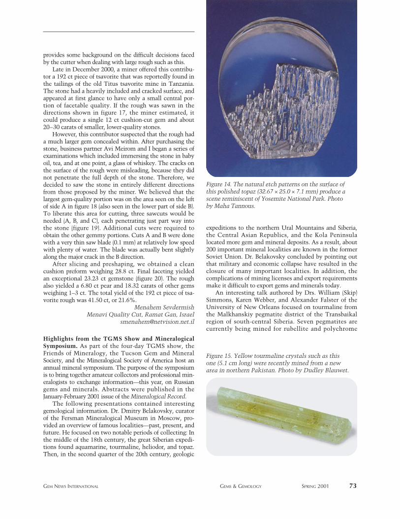
provides some background on the difficult decisions facedby the cutter when dealing with large rough such as this.
Late in December 2000, a miner offered this contribu-tor a 192 ct piece of tsavorite that was reportedly found inthe tailings of the old Titus tsavorite mine in Tanzania.The stone had a heavily included and cracked surface, andappeared at first glance to have only a small central por-tion of facetable quality. If the rough was sawn in thedirections shown in figure 17, the miner estimated, itcould produce a single 12 ct cushion-cut gem and about20–30 carats of smaller, lower-quality stones.
However, this contributor suspected that the rough hada much larger gem concealed within. After purchasing thestone, business partner Avi Meirom and I began a series ofexaminations which included immersing the stone in babyoil, tea, and at one point, a glass of whiskey. The cracks onthe surface of the rough were misleading, because they didnot penetrate the full depth of the stone. Therefore, wedecided to saw the stone in entirely different directionsfrom those proposed by the miner. We believed that thelargest gem-quality portion was on the area seen on the leftof side A in figure 18 (also seen in the lower part of side B).To liberate this area for cutting, three sawcuts would beneeded (A, B, and C), each penetrating just part way intothe stone (figure 19). Additional cuts were required toobtain the other gemmy portions. Cuts A and B were donewith a very thin saw blade (0.1 mm) at relatively low speedwith plenty of water. The blade was actually bent slightlyalong the major crack in the B direction.
After slicing and preshaping, we obtained a cleancushion preform weighing 28.8 ct. Final faceting yieldedan exceptional 23.23 ct gemstone (figure 20). The roughalso yielded a 6.80 ct pear and 18.32 carats of other gemsweighing 1–3 ct. The total yield of the 192 ct piece of tsa-vorite rough was 41.50 ct, or 21.6%.
Menahem SevdermishMenavi Quality Cut, Ramat Gan, Israel
Highlights from the TGMS Show and MineralogicalSymposium. As part of the four-day TGMS show, theFriends of Mineralogy, the Tucson Gem and MineralSociety, and the Mineralogical Society of America host anannual mineral symposium. The purpose of the symposiumis to bring together amateur collectors and professional min-eralogists to exchange information—this year, on Russiangems and minerals. Abstracts were published in theJanuary-February 2001 issue of the Mineralogical Record.
The following presentations contained interestinggemological information. Dr. Dmitry Belakovsky, curatorof the Fersman Mineralogical Museum in Moscow, pro-vided an overview of famous localities—past, present, andfuture. He focused on two notable periods of collecting: Inthe middle of the 18th century, the great Siberian expedi-tions found aquamarine, tourmaline, heliodor, and topaz.Then, in the second quarter of the 20th century, geologic
expeditions to the northern Ural Mountains and Siberia,the Central Asian Republics, and the Kola Peninsulalocated more gem and mineral deposits. As a result, about200 important mineral localities are known in the formerSoviet Union. Dr. Belakovsky concluded by pointing outthat military and economic collapse have resulted in theclosure of many important localities. In addition, thecomplications of mining licenses and export requirementsmake it difficult to export gems and minerals today.
An interesting talk authored by Drs. William (Skip)Simmons, Karen Webber, and Alexander Falster of theUniversity of New Orleans focused on tourmaline fromthe Malkhanskiy pegmatite district of the Transbaikalregion of south-central Siberia. Seven pegmatites arecurrently being mined for rubellite and polychrome
GEM NEWS INTERNATIONAL GEMS & GEMOLOGY SPRING 2001 73
Figure 14. The natural etch patterns on the surface ofthis polished topaz (32.67 × 25.0 × 7.1 mm) produce ascene reminiscent of Yosemite National Park. Photoby Maha Tannous.
Figure 15. Yellow tourmaline crystals such as thisone (5.1 cm long) were recently mined from a newarea in northern Pakistan. Photo by Dudley Blauwet.

tourmaline. Electron microprobe analyses of the tour-maline revealed elbaite compositions with a significantliddicoatite component in some samples.
Dr. Peter Lyckberg presented three lectures on gemdeposits in Russia, the Ukraine, Kazakhstan, and Tajikistan.For each region, he reviewed mining during the past fewdecades. He also clarified an often-mislabeled locality,Sherlovaya Gora in the Transbaikal region of Siberia,Russia. Called the greatest gem beryl producer in Russia, itis a greisen deposit that has been confused with another peg-matite locality in the Adun Chelon Mountain Range, whichalso produces beryl, but with different characteristics.
A new gem map of Russia and adjacent countries was
available at the TGMS show. Although printed in Russian,it is accompanied by a guide in English. The map andguide can be purchased from Mineralogical Almanac ([email protected]), P.O. Box 368, Moscow, Russia 103009.
Other gem and jewelry highlights on display at theTGMS show were:
• More than 60 Fabergé pieces from several collectors anddealers
• Fabergé memorabilia including invoices for twoImperial eggs, early catalogs, and photographs of theFabergé workshops
• The Mackay emerald necklace, featuring the largest cutemerald (168 ct) in the National Gem Collection at theSmithsonian Institution
• Large gemmy aquamarine crystals from southern India,including the 10 kg crystal pictured in the Fall 2000 GNsection (additional crystals on display weighed 2.3 kg,650 g, and 280 g)
• A 2,750 ct treated-color blue topaz, fashioned by Dr.Artmura Kirk and donated to the Virginia PolytechnicInstitute and State University.
Next year, the 48th Tucson Gem & Mineral Societyshow will feature minerals and art from Africa.
Dona M. DirlamGIA Library and Information Center, Carlsbad
Faceted vesuvianite from California. Although smallquantities of polished yellow-green vesuvianite(idocrase) from northern California have been aroundfor years, this year’s TGMS show saw the commercialavailability of faceted material (see, e.g., figure 21). Thehistoric deposit—east of Paradise on the FeatherRiver—was reopened three years ago by these contribu-tors and Ben Halpin. The deposit consists of pods andlenses of massive vesuvianite within sheared serpen-tine, and is one of the original localities for a yellow-
74 GEM NEWS INTERNATIONAL GEMS & GEMOLOGY SPRING 2001
Figure 17. The miner proposed sawing the tsavoriterough in these directions, to yield a cushion-shapeestimated at 12 ct and additional smaller gems thatwould total about 30 carats.
Figure 18. A careful examination of the tsavoriterevealed a much larger gem concealed within, so it wasdecided to saw the gem in entirely different directions.
Figure 16. Northern Pakistan is also the source ofthese yellowish green tourmalines. The largest crys-tal measures 3.5 cm tall. Courtesy of Syed TradingCo.; photo by Jeff Scovil.
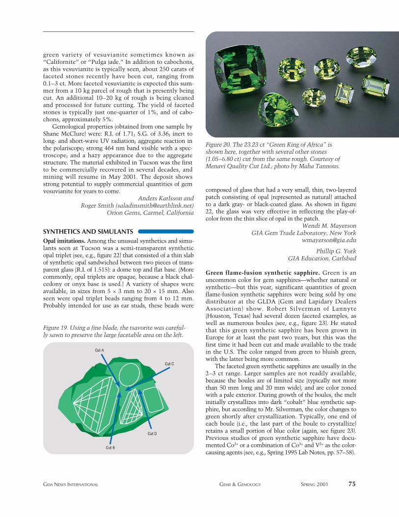
green variety of vesuvianite sometimes known as“Californite” or “Pulga jade.” In addition to cabochons,as this vesuvianite is typically seen, about 250 carats offaceted stones recently have been cut, ranging from0.1–3 ct. More faceted vesuvianite is expected this sum-mer from a 10 kg parcel of rough that is presently beingcut. An additional 10–20 kg of rough is being cleanedand processed for future cutting. The yield of facetedstones is typically just one-quarter of 1%, and of cabo-chons, approximately 5%.
Gemological properties (obtained from one sample byShane McClure) were: R.I. of 1.71; S.G. of 3.36; inert tolong- and short-wave UV radiation; aggregate reaction inthe polariscope; strong 464 nm band visible with a spec-troscope; and a hazy appearance due to the aggregatestructure. The material exhibited in Tucson was the firstto be commercially recovered in several decades, andmining will resume in May 2001. The deposit showsstrong potential to supply commercial quantities of gemvesuvianite for years to come.
Anders Karlsson and Roger Smith ([email protected])
Orion Gems, Carmel, California
SYNTHETICS AND SIMULANTSOpal imitations. Among the unusual synthetics and simu-lants seen at Tucson was a semi-transparent syntheticopal triplet (see, e.g., figure 22) that consisted of a thin slabof synthetic opal sandwiched between two pieces of trans-parent glass (R.I. of 1.515): a dome top and flat base. (Morecommonly, opal triplets are opaque, because a black chal-cedony or onyx base is used.) A variety of shapes wereavailable, in sizes from 5 × 3 mm to 20 × 15 mm. Alsoseen were opal triplet beads ranging from 4 to 12 mm.Probably intended for use as ear studs, these beads were
composed of glass that had a very small, thin, two-layeredpatch consisting of opal (represented as natural) attachedto a dark gray- or black-coated glass. As shown in figure22, the glass was very effective in reflecting the play-of-color from the thin slice of opal in the patch.
Wendi M. MayersonGIA Gem Trade Laboratory, New York
Phillip G. YorkGIA Education, Carlsbad
Green flame-fusion synthetic sapphire. Green is anuncommon color for gem sapphires—whether natural orsynthetic—but this year, significant quantities of greenflame-fusion synthetic sapphires were being sold by onedistributor at the GLDA (Gem and Lapidary DealersAssociation) show. Robert Silverman of Lannyte(Houston, Texas) had several dozen faceted examples, aswell as numerous boules (see, e.g., figure 23). He statedthat this green synthetic sapphire has been grown inEurope for at least the past two years, but this was thefirst time it had been cut and made available to the tradein the U.S. The color ranged from green to bluish green,with the latter being more common.
The faceted green synthetic sapphires are usually in the2–3 ct range. Larger samples are not readily available,because the boules are of limited size (typically not morethan 50 mm long and 20 mm wide), and are color zonedwith a pale exterior. During growth of the boules, the meltinitially crystallizes into dark “cobalt” blue synthetic sap-phire, but according to Mr. Silverman, the color changes togreen shortly after crystallization. Typically, one end ofeach boule (i.e., the last part of the boule to crystallize)retains a small portion of blue color (again, see figure 23).Previous studies of green synthetic sapphire have docu-mented Co3+ or a combination of Co3+ and V3+ as the color-causing agents (see, e.g., Spring 1995 Lab Notes, pp. 57–58).
GEM NEWS INTERNATIONAL GEMS & GEMOLOGY SPRING 2001 75
Figure 19. Using a fine blade, the tsavorite was careful-ly sawn to preserve the large facetable area on the left.
Figure 20. The 23.23 ct “Green King of Africa” isshown here, together with several other stones(1.05–6.80 ct) cut from the same rough. Courtesy ofMenavi Quality Cut Ltd.; photo by Maha Tannous.
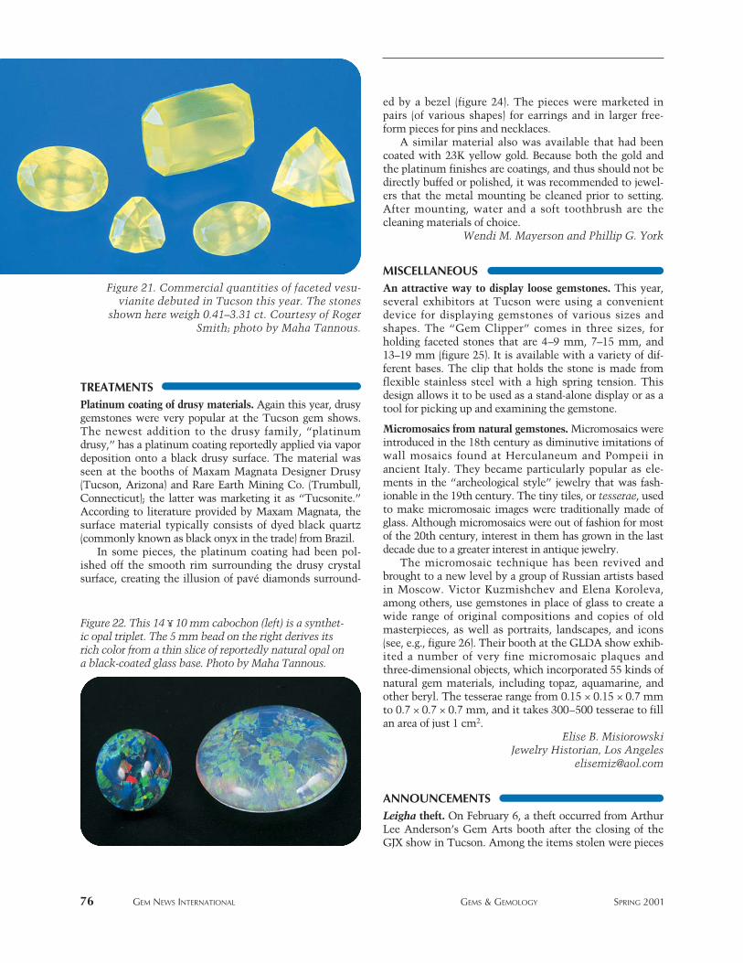
TREATMENTSPlatinum coating of drusy materials. Again this year, drusygemstones were very popular at the Tucson gem shows.The newest addition to the drusy family, “platinumdrusy,” has a platinum coating reportedly applied via vapordeposition onto a black drusy surface. The material wasseen at the booths of Maxam Magnata Designer Drusy(Tucson, Arizona) and Rare Earth Mining Co. (Trumbull,Connecticut); the latter was marketing it as “Tucsonite.”According to literature provided by Maxam Magnata, thesurface material typically consists of dyed black quartz(commonly known as black onyx in the trade) from Brazil.
In some pieces, the platinum coating had been pol-ished off the smooth rim surrounding the drusy crystalsurface, creating the illusion of pavé diamonds surround-
ed by a bezel (figure 24). The pieces were marketed inpairs (of various shapes) for earrings and in larger free-form pieces for pins and necklaces.
A similar material also was available that had beencoated with 23K yellow gold. Because both the gold andthe platinum finishes are coatings, and thus should not bedirectly buffed or polished, it was recommended to jewel-ers that the metal mounting be cleaned prior to setting.After mounting, water and a soft toothbrush are thecleaning materials of choice.
Wendi M. Mayerson and Phillip G. York
MISCELLANEOUSAn attractive way to display loose gemstones. This year,several exhibitors at Tucson were using a convenientdevice for displaying gemstones of various sizes andshapes. The “Gem Clipper” comes in three sizes, forholding faceted stones that are 4–9 mm, 7–15 mm, and13–19 mm (figure 25). It is available with a variety of dif-ferent bases. The clip that holds the stone is made fromflexible stainless steel with a high spring tension. Thisdesign allows it to be used as a stand-alone display or as atool for picking up and examining the gemstone.
Micromosaics from natural gemstones. Micromosaics wereintroduced in the 18th century as diminutive imitations ofwall mosaics found at Herculaneum and Pompeii inancient Italy. They became particularly popular as ele-ments in the “archeological style” jewelry that was fash-ionable in the 19th century. The tiny tiles, or tesserae, usedto make micromosaic images were traditionally made ofglass. Although micromosaics were out of fashion for mostof the 20th century, interest in them has grown in the lastdecade due to a greater interest in antique jewelry.
The micromosaic technique has been revived andbrought to a new level by a group of Russian artists basedin Moscow. Victor Kuzmishchev and Elena Koroleva,among others, use gemstones in place of glass to create awide range of original compositions and copies of oldmasterpieces, as well as portraits, landscapes, and icons(see, e.g., figure 26). Their booth at the GLDA show exhib-ited a number of very fine micromosaic plaques andthree-dimensional objects, which incorporated 55 kinds ofnatural gem materials, including topaz, aquamarine, andother beryl. The tesserae range from 0.15 × 0.15 × 0.7 mmto 0.7 × 0.7 × 0.7 mm, and it takes 300–500 tesserae to fillan area of just 1 cm2.
Elise B. MisiorowskiJewelry Historian, Los Angeles
ANNOUNCEMENTSLeigha theft. On February 6, a theft occurred from ArthurLee Anderson’s Gem Arts booth after the closing of theGJX show in Tucson. Among the items stolen were pieces
76 GEM NEWS INTERNATIONAL GEMS & GEMOLOGY SPRING 2001
Figure 22. This 14 ¥ 10 mm cabochon (left) is a synthet-ic opal triplet. The 5 mm bead on the right derives itsrich color from a thin slice of reportedly natural opal ona black-coated glass base. Photo by Maha Tannous.
Figure 21. Commercial quantities of faceted vesu-vianite debuted in Tucson this year. The stones
shown here weigh 0.41–3.31 ct. Courtesy of RogerSmith; photo by Maha Tannous.
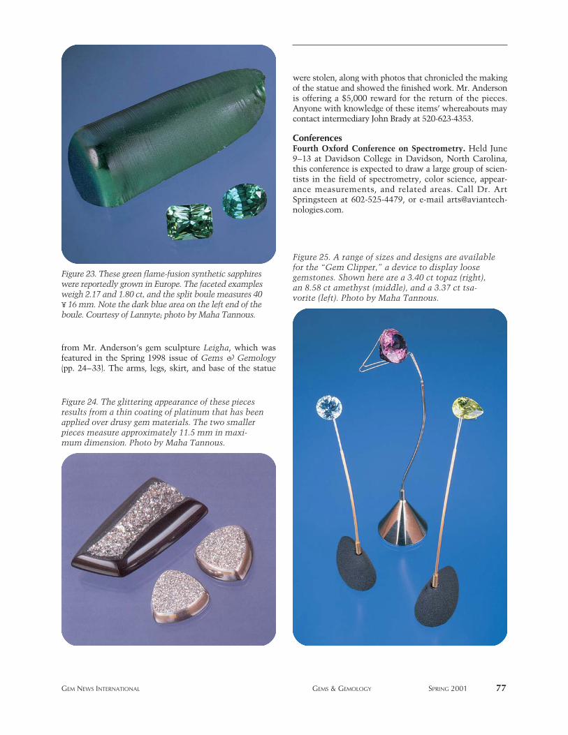
from Mr. Anderson’s gem sculpture Leigha, which wasfeatured in the Spring 1998 issue of Gems & Gemology(pp. 24–33). The arms, legs, skirt, and base of the statue
were stolen, along with photos that chronicled the makingof the statue and showed the finished work. Mr. Andersonis offering a $5,000 reward for the return of the pieces.Anyone with knowledge of these items’ whereabouts maycontact intermediary John Brady at 520-623-4353.
ConferencesFourth Oxford Conference on Spectrometry. Held June9–13 at Davidson College in Davidson, North Carolina,this conference is expected to draw a large group of scien-tists in the field of spectrometry, color science, appear-ance measurements, and related areas. Call Dr. ArtSpringsteen at 602-525-4479, or e-mail [email protected].
GEM NEWS INTERNATIONAL GEMS & GEMOLOGY SPRING 2001 77
Figure 23. These green flame-fusion synthetic sapphireswere reportedly grown in Europe. The faceted examplesweigh 2.17 and 1.80 ct, and the split boule measures 40¥ 16 mm. Note the dark blue area on the left end of theboule. Courtesy of Lannyte; photo by Maha Tannous.
Figure 25. A range of sizes and designs are availablefor the “Gem Clipper,” a device to display loosegemstones. Shown here are a 3.40 ct topaz (right),an 8.58 ct amethyst (middle), and a 3.37 ct tsa-vorite (left). Photo by Maha Tannous.
Figure 24. The glittering appearance of these piecesresults from a thin coating of platinum that has beenapplied over drusy gem materials. The two smallerpieces measure approximately 11.5 mm in maxi-mum dimension. Photo by Maha Tannous.
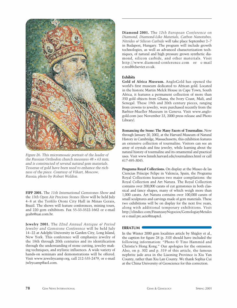
FIPP 2001. The 11th International Gemstones Show andthe 13th Open Air Precious Stones Show will be held July4–8 at the Teófilo Otoni City Hall in Minas Gerais,Brazil. The shows will feature conferences, mining tours,and 220 gem exhibitors. Fax 55-33-3522-1662 or [email protected].
Jewelry 2001. The 22nd Annual Antique & PeriodJewelry and Gemstone Conference will be held July14–22 at Adelphi University in Garden City, Long Island,New York. This conference will emphasize jewelry ofthe 18th through 20th centuries and its identificationthrough the understanding of stone cutting, jewelry mak-ing techniques, and stylistic influences. A wide variety ofhands-on seminars and demonstrations will be offered.Visit www.jewelrycamp.org, call 212-535-2479, or [email protected].
Diamond 2001. The 12th European Conference onDiamond, Diamond-Like Materials, Carbon Nanotubes,Nitrides & Silicon Carbide will take place September 2–7in Budapest, Hungary. The program will include growthtechnologies, as well as advanced characterization tech-niques, of natural and high pressure grown synthetic dia-mond, silicon carbide, and other materials. Visithttp://www.diamond-conference.com or [email protected].
ExhibitsGold of Africa Museum. AngloGold has opened theworld’s first museum dedicated to African gold. Locatedin the historic Martin Melck House in Cape Town, SouthAfrica, it features a permanent collection of more than350 gold objects from Ghana, the Ivory Coast, Mali, andSenegal. These 19th and 20th century pieces, rangingfrom crowns to jewelry, were purchased recently from theBarbier-Mueller Museum in Geneva. Visit www.anglo-gold.com (see November 23, 2000 press release and PhotoLibrary).
Romancing the Stone: The Many Facets of Tourmaline. Nowthrough January 20, 2002, at the Harvard Museum of NaturalHistory in Cambridge, Massachusetts, this exhibition featuresan extensive collection of tourmaline. Visitors can see anarray of crystals and fine jewelry, while learning about thenatural history of tourmaline and its ornamental and practicaluses. Visit www.hmnh.harvard.edu/tourmalines.html or call617-495-3045.
Programa Royal Collections. On display at the Museo de lasCiencias Príncipe Felipe in Valencia, Spain, the ProgramaRoyal Collections features two major compilations: theRoyal Collection and Art Natura. The Royal Collectioncontains over 200,000 carats of cut gemstones in both clas-sical and fancy shapes, many of which weigh more than1,000 carats. Art Natura contains over 100,000 carats ofsmall sculptures and carvings made of gem materials. Thesetwo exhibitions will be on display for the next five years,along with additional temporary exhibitions. Visithttp://elindice.com/FinanzasyNegocios/GemologiayMetalesor e-mail prc.aeie@maptel.
ERRATUMIn the Winter 2000 gem localities article by Shigley et al.,the caption for figure 28 (p. 310) should have included thefollowing information: “Photo © Tino Hammid andChristie’s Hong Kong.” Our apologies for the omission.Also, on p. 302 and p. 319 of this article, the famousnephrite jade area in the Liaoning Province is Xiu YanCounty, rather than Xiu Lan County. We thank Sophia Cuiat the China University of Geoscience for this correction.
78 GEM NEWS INTERNATIONAL GEMS & GEMOLOGY SPRING 2001
Figure 26. This micromosaic portrait of the leader ofthe Russian Orthodox church measures 48 × 63 mm,and is constructed of several natural gem materials.Tesserae of gold have been used to enhance the rich-ness of the piece. Courtesy of Vikart, Moscow,Russia; photo by Robert Weldon.
GEMS & GEMOLOGY CHALLENGE GEMS & GEMOLOGY SPRING 2001 79
C hallengehe following 25 questions are based on informa-
tion from the four 2000 issues of Gems & Gemology.Refer to the feature articles and “Notes and NewTechniques” in those issues to find the single bestanswer for each question; then mark your choice onthe response card provided in this issue. (Sorry, nophotocopies or facsimiles will be accepted; contactthe Subscriptions Department—[email protected]—ifyou wish to purchase additional copies of this issue.)Mail the card so that we receive it no later than Mon-day, August 6, 2001. Please include your name and
address. All entries will be acknowledged with a let-ter and an answer key after the due date.
Score 75% or better, and you will receive a GIAContinuing Education Certificate. If you are a member ofthe GIA Alumni Association, you will earn 5 Carat Pointstoward GIA’s Alumni Circle of Achievement. (Be sure toinclude your GIA Alumni membership number on youranswer card and submit your Carat card for credit.) Earna perfect score, and your name will also be featured inthe Fall 2001 issue of Gems & Gemology. Good luck!
1. What diamond type can be changedfrom brown to greenish yellow byHPHT processing?
A. Type IIaB. Type IIbC. Type IaD. Type Ib
2. The most common type of treatment(aside from dyeing) used for gemscontinues to be
A. irradiation.B. heat treatment.C. diffusion treatment.D. fracture filling.
3. Which of these analytical techniquescould not be considered “mature” togemologists in the 1990s?
A. Isotopic studiesB. Ultraviolet-visible spec-
troscopy
C. Electron microprobe analysisD. X-ray fluorescence spectrometry
4. If bead-nucleated Chinese freshwa-ter cultured pearls do become com-mon in the future, their nature willbe readily identifiable by
A. Fourier-transform infrared spectroscopy.
B. magnification.C. X-radiography.D. X-ray diffraction.
5. Most of the corundum mined fromthe Jegdalek deposit in east-centralAfghanistan is
A. ruby.B. pink sapphire.C. blue sapphire.D. bicolored blue and red-to-pink
corundum.
6. The emphasis on fancy-color dia-monds in jewelry during the 1990swas primarily due to the greateravailability of fancy brown, yellow,and pink diamonds from
A. Australia.B. Canada.C. Brazil.D. Russia.
7. The larger size of Chinese freshwatercultured pearls over the last severalyears can be attributed primarily to
A. a longer cultivation period andthe use of younger mussels.
B. the change from the Hyriopsis cumingi mussel to the Cristariaplicata.
C. the use of mantle-tissue nuclei.D. the use of reject cultured
pearls as nuclei.
T

80 GEMS & GEMOLOGY CHALLENGE GEMS & GEMOLOGY SPRING 2001
8. In Myanmar’s Jade Tract, minersoften can identify the occasionaljadeite boulder by
A. its slightly sticky feel.B. the distinct ringing sound it
makes when struck with a metal tool.
C. its greater heft than other typesof rock in the conglomerate.
D. all of the above.
9. Spectral features due to single sub-stitutional nitrogen atoms in a nomi-nally type IIa diamond provide anindication of
A. fracture filling.B. HPHT treatment.C. irradiation.D. a surface coating.
10. The purple to purplish red color ofchromium-bearing taaffeites is afunction of the relative amounts ofchromium and _______ present.A. cobaltB. titaniumC. ironD. manganese
11. A new laser treatment for dia-monds, which typically does nothave a surface-reaching drill hole,works best onA. small inclusions.B. inclusions deep within a stone.C. dark inclusions near the sur-
face.D. light inclusions far from the
stone’s surface.
12.Diagnostic inclusions, in the formof ______, were documented inTairus hydrothermal syntheticemeralds in the 1990s.A. iron oxidesB. platinum plateletsC. flux “fingerprints”D. chromite
13.Evidence that a near-colorless typeIIa diamond has been HPHT treat-ed can be provided by a combina-tion ofA. photoluminescence spectra
and inclusions.B. graining and cathodolumines-
cence.
C. X-ray topography and infrared spectra.
D. infrared spectra and graining.
14. The most significant amethyst-producing country of the 1990s wasA. Zambia.B. Uruguay.C. Brazil.D. Canada.
15. Diamonds filled with Oved’s newXL-21 glass formulation are char-acterized byA. a strong flash effect.B. the “Oved” logo inscribed on
a bezel facet.C. the detection of Pb and Bi by
EDXRF analysis.D. all of the above.
16. Which imitation rough was mostcommon in the 1990s?A. Imitation diamond crystalsB. Imitation ruby crystalsC. Imitation sapphire crystalsD. Imitation emerald crystals
17. Which significant technologicalchallenge of the 1980s remained inthe 1990s?A. Identifying synthetic diamonds
by their fluorescence B. Determining origin of color for
green diamondsC. Identifying GE POL diamondsD. Characterizing diamond fillers
18. HPHT-treated greenish yellow toyellowish green diamonds mayshowA. chalky greenish yellow fluores-
cence.B. strong green “transmission”
(luminescence to visible light).C. fractures with etched, frosted
textures or partial graphitization.D. all of the above.
19. Most of the shell jewelry discov-ered at archeological sites on theisland of Antigua was manufac-tured from the ______ shell.A. queen conchB. nautilus
C. abaloneD. thorny oyster
20. The ________ effect of one gemmaterial overlaid on another wasintroduced to the jewelry world inthe 1990s.A. “optic dish”B. “drusy”C. “Mystère”D. “trompe l’oeil”
21. Gem-quality haüyne is rarely seenin jewelry because ofA. its high specific gravity and
low luster.B. its rarity and low hardness.C. its treatment with paraffin wax.D. its popularity as a collector’s
stone.
22. X-ray diffraction analysis identifiedlazurite and _______ as the princi-pal minerals in samples of first-grade lapis lazuli from both Chileand Afghanistan.A. wollastoniteB. bariteC. pyriteD. calcite
23. The first major demantoid garnetlocality outside of Russia was dis-covered in ________ in the mid-1990s.A. NamibiaB. TanzaniaC. ChinaD. Madagascar
24. The most important factor in theevaluation of Burmese jadeite is A. diaphaneity.B. texture.C. color.D. cut.
25. Sapphires from the AntsirananaProvince of Madagascar showinternal features typical of ______deposits.A. marble-hostedB. metamorphicC. basaltic-magmaticD. alluvial
BOOK REVIEWS GEMS & GEMOLOGY SPRING 2001 81
Jeweled Bugs and ButterfliesBy Marilyn Nissenson and SusanJonas, 120 pp., illus., publ. by HarryN. Abrams, New York, 2000.US$29.95*
If you’re a lover of jeweled bugs andbutterflies, this is the book for you. Itis highlighted by 127 magnificent full-color photographs of objects related tothis theme. The fine quality of thephotographs shows off the detail of thecreatures. You will enjoy scarabs fromancient Egypt and objects from the ArtNouveau period (featuring the work ofRené Lalique), as well as pieces frommany other artists and eras.
While at first glance you mightpurchase this book for your coffeetable, it offers much more. You willgain a historical perspective on jew-eled bugs through the ages, discovertheir lore, and even get a lesson inentomology. Did you know thatinsects first appeared on Earth some350–400 million years ago? Or that atleast 750,000 species of insects havebeen identified? Are you curiousabout the Art Nouveau period?Reading this text will give you someinsight into these topics.
The book is divided into six chap-ters, by category of bugs. The first sec-tion is on “Creepy Crawlers;” spidersand beetles, among the most displeas-ing creatures to some, are featured injeweled splendor. The next section isdevoted to “Scarabs,” or dung beetles.Perhaps the first insects to be used injewelry, scarabs were worn for protec-tion by early Egyptians. Flyinginsects—especially bees—are featuredin “Buzzers and Stingers.” Next, in“Dragonflies,” you’ll see pieces withdelicate wings of plique-à-jour enamel.
The juxtaposition of women andinsects by Art Nouveau designers fol-lows in “Winged Women.” The lastsection features the bejeweled wings of“Butterflies and Moths.”
The authors have compiled a won-derful tribute to Jeweled Bugs and But-terflies. I would highly recommendthis book to anyone who has an affin-ity for these curious creatures and theperiod jewelry in which they were fea-tured so prominently.
DIANE SAITOGemological Institute of America
Carlsbad, California
Paulding Farnham:Tiffany’s Lost GeniusBy John Loring, 151 pp., illus., publ.by Harry N. Abrams, New York,2000. US$49.50*
As the 19th century eased into the20th, George Paulding Farnham ofTiffany and Co. was one of theworld’s most celebrated designers ofjewelry and silver. His use of Ameri-can gemstones is renowned (his beau-tiful iris brooch [illustrated on p. 31of the Spring 1995 issue of Gems &Gemology] is the quintessentialMontana sapphire jewel), and hisenameled orchids are highly prizedby collectors of fine jewelry. I person-ally had always wondered what thereasons were behind his apparentlyabrupt departure from Tiffany’s, andJohn Loring not only answers thisquestion, but he also gives insightinto Farnham’s personal history andinspirations.
The book’s preface and introduc-tion track Farnham’s 22 years atTiffany & Co. while giving glimpses
into his personal life. They also ex-plain that his departure came whenLouis Comfort Tiffany inherited con-trol of the company. Tiffany and Farn-ham had radically different views ondesign, and conflict was inevitable.The book is then divided into chaptersthat categorize Farnham’s work. Thefirst chapter, “Nature,” highlightsFarnham’s beautiful floral brooches,many of which incorporated enamelalong with gemstones. It also show-cases a number of pieces that featurebees, beetles, lizards, snakes, andbirds. The next chapter, “Orchids,”features Farnham’s famous enameledorchid brooches. Originally fabricatedfor the 1889 Paris Exposition Univer-selle, these brooches were realisticallyrendered in enamel, gold, and, often,gemstones. Highly collectible, theycommand high prices at auctiontoday. “Native American Design” dis-plays incredible bowls, vases, and ves-sels—in most cases, fashioned in sil-ver—that were inspired by NativeAmerican pottery. There are alsochapters on “The Louis’ Revival,”“Victorianism,” and “The Renais-sance Revival,” which all do a won-derful job of discussing and illustrat-ing these influences on Farnham’sjewelry and silver.
Loring’s book is lavishly illustrat-ed, with photographs of many piecesas well as with actual renderings andsketches in Farnham’s hand. They
2001Book REVIEWS
EDITORSSusan B. JohnsonJana E. Miyahira-Smith
*This book is available for pur-chase through the GIA Bookstore,5345 Armada Drive, Carlsbad, CA92008. Telephone: (800) 421-7250,ext. 4200; outside the U.S. (760)603-4200. Fax: (760) 603-4266.
82 BOOK REVIEWS GEMS & GEMOLOGY SPRING 2001
reveal Paulding Farnham’s brillianceand flair. In the preface, John Loringstates that his book’s mission is to“publish a substantial portion ofPaulding Farnham’s long-lostdesigns . . . . and to restore his repu-tation to its rightful position.” He hassucceeded with a visually attractive,easy-to-read, fascinating text.
JANA E. MIYAHIRA-SMITHGemological Institute of America
Carlsbad, California
The Crown Jewels:The History of the CoronationRegalia in the Jewel House ofthe Tower of LondonBy C. Blair, A. Grimwade, R. R.Harding, E. A. Jobbins, D. King,R. W. Lightbown, and K. Scarratt.Volume I: The History, 812 pp.;Volume II: The Catalogue, 630 pp.Illus., publ. by The Stationery Office,London, 1998. US$1,650
These two sumptuously produced vol-umes, with text and photographs print-ed on substantial, silk-surfaced paper,record the results of research into thehistory of the English Coronation andassociated regalia in greater detail thanhas ever before been possible. Volume Iis concerned entirely with the originsand history of the Coronation cere-mony, but it is Volume II that docu-ments a detailed examination of theCrown Jewels, revealing many discov-eries and new insights about the gem-stones. Each item has been newlyphotographed, and the team of threegemologists has taken the opportuni-ty to examine the jewels with sophis-ticated gemological techniques.
The catalogue illustrates anddescribes the regalia, including notonly the numerous crowns, orbs, andscepters, but also the various swords,plate, and textiles. Each chapterbegins with a brief abstract giving thesize and appearance of the item, fol-lowed by a history of the various for-mats and vicissitudes. The descrip-tion of each major item concludes
with a “gemmological commentary,”and it is here that we get a listing ofthe sizes and weights of all the majorgemstones, including details of theirsurface imperfections and any visibleinclusions.
One of the many delights of thiswork lies in the numerous color pho-tographs of the regalia. The price ofthese two magnificent volumes mayprevent one from dashing out to buya set, but this work records for poster-ity far more details of the gemstonesin the regalia than have been avail-able hitherto.
R. A. HOWIERoyal Holloway,
University of London
OTHER BOOKS RECEIVEDColored Stones of Yakutia and Placesof Their Origin, by V. G. Gadiatovand V. K. Marshinsev, 328 pp., illus.,publ. by Yekaterinburg Bank ofCultural Information, Yekaterinburg,Russia, 2000, 150 rubles (aboutUS$5.25) [in Russian]. For more than300 years, the remote Siberian regionof Yakutia has been a generousprovider of gem materials for Russiaand the entire world. Diamond, ame-thyst, garnet, topaz, and several othergem materials (as well as ornamentalstones) are described, according totheir location, characteristics, andgeologic occurrence. The authors’analysis of Yakutia’s geology suggestsinteresting directions for future devel-opment of the gem resources. Readersalso will find useful informationabout the economics and resourcemanagement of the rough gem miner-als, as well as facts about the globalgem market.
Although the book contains a sig-nificant amount of scientific materialand professional terminology, it isintended for a very broad audience—admirers of gemstones. Geologiccharts, maps, and numerous colored
illustrations of minerals provide awealth of visual information thatadds to the enjoyment of this book.
VLADISLAV DOMBROVSKIYGIA Gem Trade Laboratory
Carlsbad, California
Gemmologia Europa VII—EuropeanGemmologists on the Emerald, edit-ed by Margherita Superchi, 221 pp.,illus., publ. by CISGEM, Milan,Italy, 2000, 35,000 lira (aboutUS$16.00) [in Italian and English].This volume on emerald is the pro-ceedings of the seventh GemmologiaEuropa (Milan, 1998), a biennial con-ference sponsored by the CentroInformazione e Servizi Gemmologici(CISGEM). Included are illustratedtranscripts of presentations by JanKanis (African localities), DietmarSchwarz (South American, Asian, andAustralian localities), Henry Hänni(synthesis and enhancement), ElenaGambini (CISGEM Laboratory emer-ald grading procedures), and GiorgioGraziani (geographic provenance ofarcheological emeralds).
STUART D. OVERLINGemological Institute of America
Carlsbad, California
Mughals , Mahara jas and theMahatma, by K. R. N. Swamy, 265pp., illus., publ. by Harper CollinsPublishers India, New Delhi, 1997,US$18.95. This is a collection of 39fascinating episodes in Indian history,12 of which concern famous gemsand diamonds, royal treasuries, andgem-encrusted thrones. Many of theremaining episodes revolve aroundthe British Raj, Mahatma Gandhi,politics, and wars. The contributionsto the history of Indian treasures, dia-monds, and jewels make this bookeasily worth its price for the gem andjewelry enthusiast.
JOHN SINKANKASPeri Lithon Books
San Diego, California
COLORED STONES ANDORGANIC MATERIALSAcute toxicity of formaldehyde to the pearl oyster Pinctada
fucata martensii. K. Takayanagi, T. Sakami, M. Shiraishi,and H. Yokoyama, Water Research, Vol. 34, No. 1, 2000,pp. 93–98.
Formaldehyde is often used in fish hatcheries to treat parasiticinfections. It is then discharged into the hatchery effluent,where it enters the marine environment. Although formalde-hyde is biodegradable, there are few reliable data on its effectson saltwater organisms over time, particularly on nonmigratoryshellfish that are vulnerable to degradation of water quality.Accordingly, acute toxicities of formaldehyde to one- and two-year-old Akoya pearl oysters (Pinctada fucata martensii) weredetermined in a controlled laboratory environment. The oysterswere not given any food during the experiments. Test solutionswere made by adding various concentrations of formaldehyde tosand-filtered seawater. The oysters were observed at 24-hourintervals, and any dead oysters were removed.
During the first 24 hours, the oysters reduced their respira-tion by minimizing water intake to avoid exposure to theformaldehyde. However, within 96 hours all oysters had died. Asharp decrease in formaldehyde levels in the test solutions wasobserved during the experiment, especially in solutions withlower concentrations of the chemical. The results suggest thatpearl oysters can detect the presence of formaldehyde in theirsurroundings and that they possess some form of defense mech-anism from its toxic effects but, with time, they will succumbto its effects. No mortality was observed in a control group thatwas not exposed to formaldehyde. MT
Gemological ABSTRACTS
2001EDITOR
A. A. LevinsonUniversity of Calgary
Calgary, Alberta, Canada
REVIEW BOARDTroy Blodgett
GIA Gem Trade Laboratory, Carlsbad
Anne M. BlumerBloomington, Illinois
Peter R. BuerkiGIA Research, Carlsbad
Jo Ellen ColeGIA Museum Services, Carlsbad
R. A. HowieRoyal Holloway, University of London
Jeff LewisNew Orleans, Louisiana
Taijin LuGIA Research, Carlsbad
Wendi M. MayersonGIA Gem Trade Laboratory, NewYork
James E. ShigleyGIA Research, Carlsbad
Jana E. Miyahira-SmithGIA Education, Carlsbad
Kyaw Soe MoeGIA Gem Trade Laboratory, Carlsbad
Maha TannousGIA Gem Trade Laboratory, Carlsbad
Rolf TatjeDuisburg University, Germany
Paige TullosGIA Gem Trade Laboratory, Carlsbad
Sharon WakefieldNorthwest Gem Lab, Boise, Idaho
June YorkGIA Gem Trade Laboratory, Carlsbad
Philip G. YorkGIA Education, Carlsbad
This section is designed to provide as complete a record as prac-tical of the recent literature on gems and gemology. Articles areselected for abstracting solely at the discretion of the section edi-tor and his reviewers, and space limitations may require that weinclude only those articles that we feel will be of greatest interestto our readership.
Requests for reprints of articles abstracted must be addressed tothe author or publisher of the original material.
The reviewer of each article is identified by his or her initials at theend of each abstract. Guest reviewers are identified by their fullnames. Opinions expressed in an abstract belong to the abstrac-ter and in no way reflect the position of Gems & Gemology or GIA.© 2001 Gemological Institute of America
GEMOLOGICAL ABSTRACTS GEMS & GEMOLOGY SPRING 2001 83
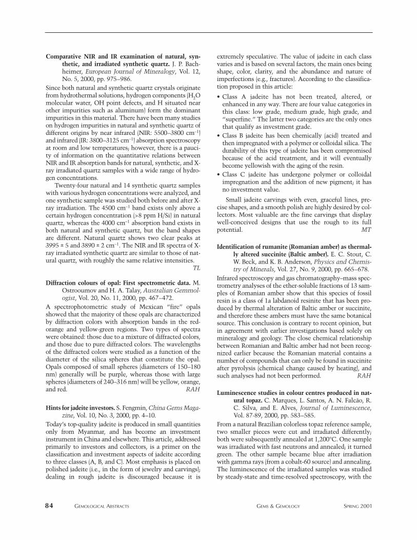
84 GEMOLOGICAL ABSTRACTS GEMS & GEMOLOGY SPRING 2001
Comparative NIR and IR examination of natural, syn-thetic, and irradiated synthetic quartz. J. P. Bach-heimer, European Journal of Mineralogy, Vol. 12,No. 5, 2000, pp. 975–986.
Since both natural and synthetic quartz crystals originatefrom hydrothermal solutions, hydrogen components (H2Omolecular water, OH point defects, and H situated nearother impurities such as aluminum) form the dominantimpurities in this material. There have been many studieson hydrogen impurities in natural and synthetic quartz ofdifferent origins by near infrared (NIR: 5500–3800 cm−1)and infrared (IR: 3800–3125 cm−1) absorption spectroscopyat room and low temperatures; however, there is a pauci-ty of information on the quantitative relations betweenNIR and IR absorption bands for natural, synthetic, and X-ray irradiated quartz samples with a wide range of hydro-gen concentrations.
Twenty-four natural and 14 synthetic quartz sampleswith various hydrogen concentrations were analyzed, andone synthetic sample was studied both before and after X-ray irradiation. The 4500 cm−1 band exists only above acertain hydrogen concentration (>8 ppm H/Si) in naturalquartz, whereas the 4000 cm−1 absorption band exists inboth natural and synthetic quartz, but the band shapesare different. Natural quartz shows two clear peaks at3995 ± 5 and 3890 ± 2 cm−1. The NIR and IR spectra of X-ray irradiated synthetic quartz are similar to those of nat-ural quartz, with roughly the same relative intensities.
TL
Diffraction colours of opal: First spectrometric data. M.Ostrooumov and H. A. Talay, Australian Gemmol-ogist, Vol. 20, No. 11, 2000, pp. 467–472.
A spectrophotometric study of Mexican “fire” opalsshowed that the majority of these opals are characterizedby diffraction colors with absorption bands in the red-orange and yellow-green regions. Two types of spectrawere obtained: those due to a mixture of diffracted colors,and those due to pure diffracted colors. The wavelengthsof the diffracted colors were studied as a function of thediameter of the silica spheres that constitute the opal.Opals composed of small spheres (diameters of 150–180nm) generally will be purple, whereas those with largespheres (diameters of 240–316 nm) will be yellow, orange,and red. RAH
Hints for jadeite investors. S. Fengmin, China Gems Maga-zine, Vol. 10, No. 3, 2000, pp. 4–10.
Today’s top-quality jadeite is produced in small quantitiesonly from Myanmar, and has become an investmentinstrument in China and elsewhere. This article, addressedprimarily to investors and collectors, is a primer on theclassification and investment aspects of jadeite accordingto three classes (A, B, and C). Most emphasis is placed onpolished jadeite (i.e., in the form of jewelry and carvings);dealing in rough jadeite is discouraged because it is
extremely speculative. The value of jadeite in each classvaries and is based on several factors, the main ones beingshape, color, clarity, and the abundance and nature ofimperfections (e.g., fractures). According to the classifica-tion proposed in this article:
• Class A jadeite has not been treated, altered, orenhanced in any way. There are four value categories inthis class: low grade, medium grade, high grade, and“superfine.” The latter two categories are the only onesthat qualify as investment grade.
• Class B jadeite has been chemically (acid) treated andthen impregnated with a polymer or colloidal silica. Thedurability of this type of jadeite has been compromisedbecause of the acid treatment, and it will eventuallybecome yellowish with the aging of the resin.
• Class C jadeite has undergone polymer or colloidalimpregnation and the addition of new pigment; it hasno investment value.
Small jadeite carvings with even, graceful lines, pre-cise shapes, and a smooth polish are highly desired by col-lectors. Most valuable are the fine carvings that displaywell-conceived designs that use the rough to its fullpotential. MT
Identification of rumanite (Romanian amber) as thermal-ly altered succinite (Baltic amber). E. C. Stout, C.W. Beck, and K. B. Anderson, Physics and Chemis-try of Minerals, Vol. 27, No. 9, 2000, pp. 665–678.
Infrared spectroscopy and gas chromatography–mass spec-trometry analyses of the ether-soluble fractions of 13 sam-ples of Romanian amber show that this species of fossilresin is a class of 1a labdanoid resinite that has been pro-duced by thermal alteration of Baltic amber or succinite,and therefore these ambers must have the same botanicalsource. This conclusion is contrary to recent opinion, butin agreement with earlier investigations based solely onmineralogy and geology. The close chemical relationshipbetween Romanian and Baltic amber had not been recog-nized earlier because the Romanian material contains anumber of compounds that can only be found in succiniteafter pyrolysis (chemical change caused by heating), andsuch analyses had not been performed. RAH
Luminescence studies in colour centres produced in nat-ural topaz. C. Marques, L. Santos, A. N. Falcão, R.C. Silva, and E. Alves, Journal of Luminescence,Vol. 87-89, 2000, pp. 583–585.
From a natural Brazilian colorless topaz reference sample,two smaller pieces were cut and irradiated differently;both were subsequently annealed at 1,200°C. One samplewas irradiated with fast neutrons and annealed; it turnedgreen. The other sample became blue after irradiationwith gamma rays (from a cobalt-60 source) and annealing.The luminescence of the irradiated samples was studiedby steady-state and time-resolved spectroscopy, with the
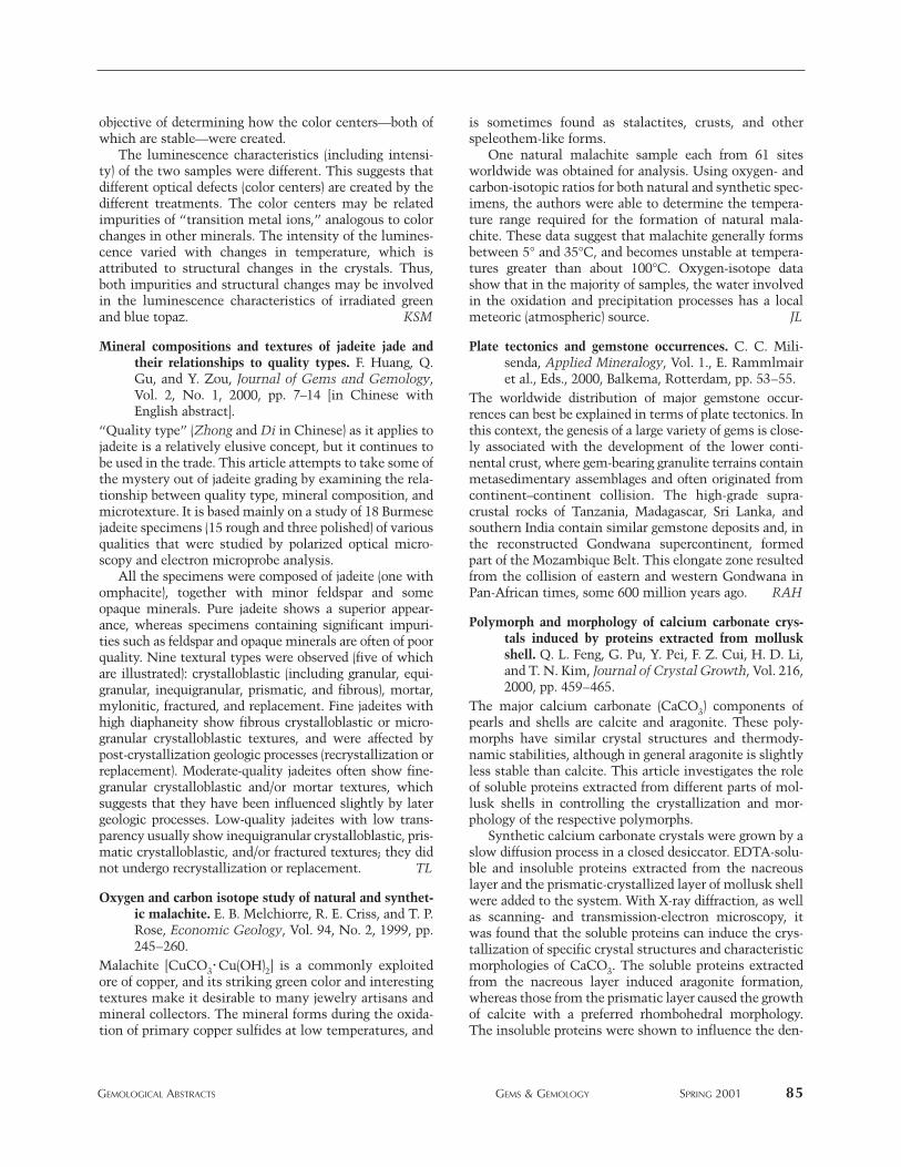
objective of determining how the color centers—both ofwhich are stable—were created.
The luminescence characteristics (including intensi-ty) of the two samples were different. This suggests thatdifferent optical defects (color centers) are created by thedifferent treatments. The color centers may be relatedimpurities of “transition metal ions,” analogous to colorchanges in other minerals. The intensity of the lumines-cence varied with changes in temperature, which isattributed to structural changes in the crystals. Thus,both impurities and structural changes may be involvedin the luminescence characteristics of irradiated greenand blue topaz. KSM
Mineral compositions and textures of jadeite jade andtheir relationships to quality types. F. Huang, Q.Gu, and Y. Zou, Journal of Gems and Gemology,Vol. 2, No. 1, 2000, pp. 7–14 [in Chinese withEnglish abstract].
“Quality type” (Zhong and Di in Chinese) as it applies tojadeite is a relatively elusive concept, but it continues tobe used in the trade. This article attempts to take some ofthe mystery out of jadeite grading by examining the rela-tionship between quality type, mineral composition, andmicrotexture. It is based mainly on a study of 18 Burmesejadeite specimens (15 rough and three polished) of variousqualities that were studied by polarized optical micro-scopy and electron microprobe analysis.
All the specimens were composed of jadeite (one withomphacite), together with minor feldspar and someopaque minerals. Pure jadeite shows a superior appear-ance, whereas specimens containing significant impuri-ties such as feldspar and opaque minerals are often of poorquality. Nine textural types were observed (five of whichare illustrated): crystalloblastic (including granular, equi-granular, inequigranular, prismatic, and fibrous), mortar,mylonitic, fractured, and replacement. Fine jadeites withhigh diaphaneity show fibrous crystalloblastic or micro-granular crystalloblastic textures, and were affected bypost-crystallization geologic processes (recrystallization orreplacement). Moderate-quality jadeites often show fine-granular crystalloblastic and/or mortar textures, whichsuggests that they have been influenced slightly by latergeologic processes. Low-quality jadeites with low trans-parency usually show inequigranular crystalloblastic, pris-matic crystalloblastic, and/or fractured textures; they didnot undergo recrystallization or replacement. TL
Oxygen and carbon isotope study of natural and synthet-ic malachite. E. B. Melchiorre, R. E. Criss, and T. P.Rose, Economic Geology, Vol. 94, No. 2, 1999, pp.245–260.
Malachite [CuCO3·Cu(OH)2] is a commonly exploitedore of copper, and its striking green color and interestingtextures make it desirable to many jewelry artisans andmineral collectors. The mineral forms during the oxida-tion of primary copper sulfides at low temperatures, and
is sometimes found as stalactites, crusts, and otherspeleothem-like forms.
One natural malachite sample each from 61 sitesworldwide was obtained for analysis. Using oxygen- andcarbon-isotopic ratios for both natural and synthetic spec-imens, the authors were able to determine the tempera-ture range required for the formation of natural mala-chite. These data suggest that malachite generally formsbetween 5° and 35°C, and becomes unstable at tempera-tures greater than about 100°C. Oxygen-isotope datashow that in the majority of samples, the water involvedin the oxidation and precipitation processes has a localmeteoric (atmospheric) source. JL
Plate tectonics and gemstone occurrences. C. C. Mili-senda, Applied Mineralogy, Vol. 1., E. Rammlmairet al., Eds., 2000, Balkema, Rotterdam, pp. 53–55.
The worldwide distribution of major gemstone occur-rences can best be explained in terms of plate tectonics. Inthis context, the genesis of a large variety of gems is close-ly associated with the development of the lower conti-nental crust, where gem-bearing granulite terrains containmetasedimentary assemblages and often originated fromcontinent–continent collision. The high-grade supra-crustal rocks of Tanzania, Madagascar, Sri Lanka, andsouthern India contain similar gemstone deposits and, inthe reconstructed Gondwana supercontinent, formedpart of the Mozambique Belt. This elongate zone resultedfrom the collision of eastern and western Gondwana inPan-African times, some 600 million years ago. RAH
Polymorph and morphology of calcium carbonate crys-tals induced by proteins extracted from molluskshell. Q. L. Feng, G. Pu, Y. Pei, F. Z. Cui, H. D. Li,and T. N. Kim, Journal of Crystal Growth, Vol. 216,2000, pp. 459–465.
The major calcium carbonate (CaCO3) components ofpearls and shells are calcite and aragonite. These poly-morphs have similar crystal structures and thermody-namic stabilities, although in general aragonite is slightlyless stable than calcite. This article investigates the roleof soluble proteins extracted from different parts of mol-lusk shells in controlling the crystallization and mor-phology of the respective polymorphs.
Synthetic calcium carbonate crystals were grown by aslow diffusion process in a closed desiccator. EDTA-solu-ble and insoluble proteins extracted from the nacreouslayer and the prismatic-crystallized layer of mollusk shellwere added to the system. With X-ray diffraction, as wellas scanning- and transmission-electron microscopy, itwas found that the soluble proteins can induce the crys-tallization of specific crystal structures and characteristicmorphologies of CaCO3. The soluble proteins extractedfrom the nacreous layer induced aragonite formation,whereas those from the prismatic layer caused the growthof calcite with a preferred rhombohedral morphology.The insoluble proteins were shown to influence the den-
GEMOLOGICAL ABSTRACTS GEMS & GEMOLOGY SPRING 2001 85
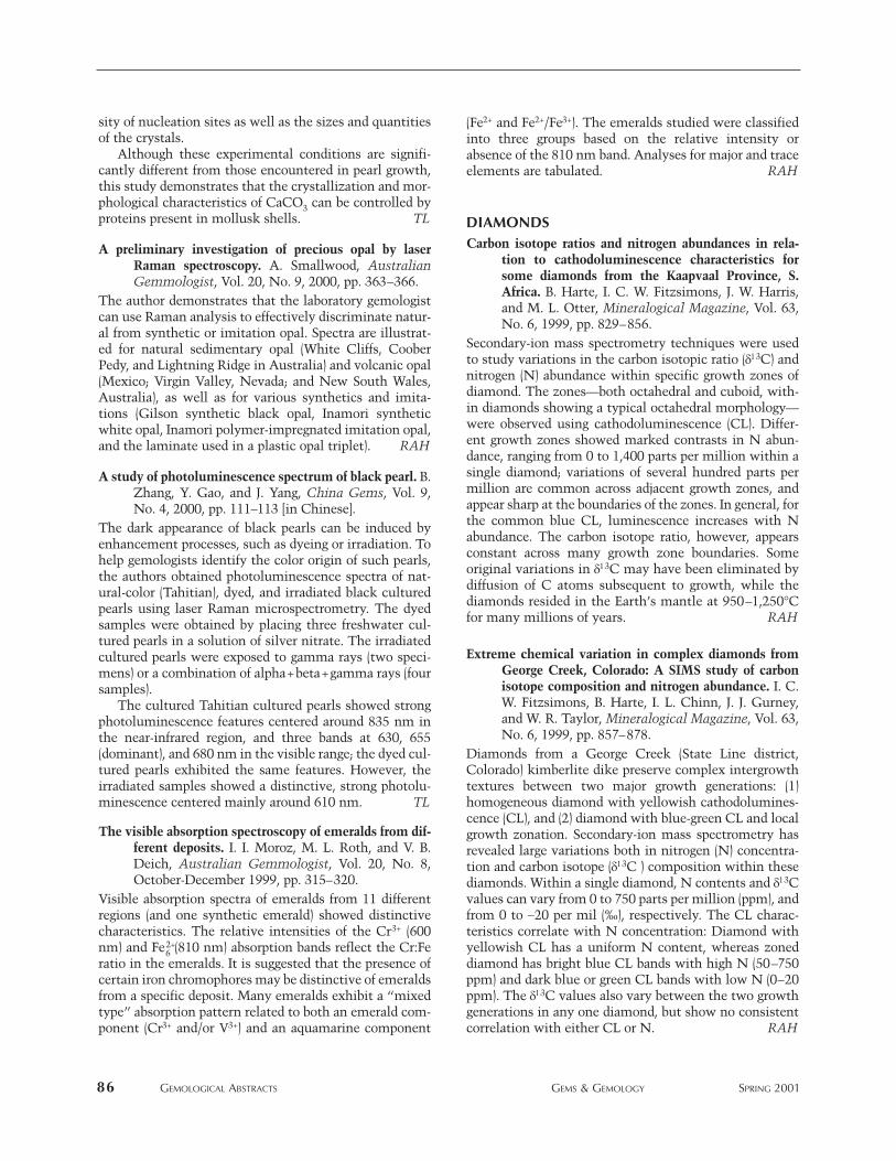
sity of nucleation sites as well as the sizes and quantitiesof the crystals.
Although these experimental conditions are signifi-cantly different from those encountered in pearl growth,this study demonstrates that the crystallization and mor-phological characteristics of CaCO3 can be controlled byproteins present in mollusk shells. TL
A preliminary investigation of precious opal by laserRaman spectroscopy. A. Smallwood, AustralianGemmologist, Vol. 20, No. 9, 2000, pp. 363–366.
The author demonstrates that the laboratory gemologistcan use Raman analysis to effectively discriminate natur-al from synthetic or imitation opal. Spectra are illustrat-ed for natural sedimentary opal (White Cliffs, CooberPedy, and Lightning Ridge in Australia) and volcanic opal(Mexico; Virgin Valley, Nevada; and New South Wales,Australia), as well as for various synthetics and imita-tions (Gilson synthetic black opal, Inamori syntheticwhite opal, Inamori polymer-impregnated imitation opal,and the laminate used in a plastic opal triplet). RAH
A study of photoluminescence spectrum of black pearl. B.Zhang, Y. Gao, and J. Yang, China Gems, Vol. 9,No. 4, 2000, pp. 111–113 [in Chinese].
The dark appearance of black pearls can be induced byenhancement processes, such as dyeing or irradiation. Tohelp gemologists identify the color origin of such pearls,the authors obtained photoluminescence spectra of nat-ural-color (Tahitian), dyed, and irradiated black culturedpearls using laser Raman microspectrometry. The dyedsamples were obtained by placing three freshwater cul-tured pearls in a solution of silver nitrate. The irradiatedcultured pearls were exposed to gamma rays (two speci-mens) or a combination of alpha+beta+gamma rays (foursamples).
The cultured Tahitian cultured pearls showed strongphotoluminescence features centered around 835 nm inthe near-infrared region, and three bands at 630, 655(dominant), and 680 nm in the visible range; the dyed cul-tured pearls exhibited the same features. However, theirradiated samples showed a distinctive, strong photolu-minescence centered mainly around 610 nm. TL
The visible absorption spectroscopy of emeralds from dif-ferent deposits. I. I. Moroz, M. L. Roth, and V. B.Deich, Australian Gemmologist, Vol. 20, No. 8,October-December 1999, pp. 315–320.
Visible absorption spectra of emeralds from 11 differentregions (and one synthetic emerald) showed distinctivecharacteristics. The relative intensities of the Cr3+ (600nm) and Fe2+
6 (810 nm) absorption bands reflect the Cr:Feratio in the emeralds. It is suggested that the presence ofcertain iron chromophores may be distinctive of emeraldsfrom a specific deposit. Many emeralds exhibit a “mixedtype” absorption pattern related to both an emerald com-ponent (Cr3+ and/or V3+) and an aquamarine component
(Fe2+ and Fe2+/Fe3+). The emeralds studied were classifiedinto three groups based on the relative intensity orabsence of the 810 nm band. Analyses for major and traceelements are tabulated. RAH
DIAMONDSCarbon isotope ratios and nitrogen abundances in rela-
tion to cathodoluminescence characteristics forsome diamonds from the Kaapvaal Province, S.Africa. B. Harte, I. C. W. Fitzsimons, J. W. Harris,and M. L. Otter, Mineralogical Magazine, Vol. 63,No. 6, 1999, pp. 829–856.
Secondary-ion mass spectrometry techniques were usedto study variations in the carbon isotopic ratio (δ13C) andnitrogen (N) abundance within specific growth zones ofdiamond. The zones—both octahedral and cuboid, with-in diamonds showing a typical octahedral morphology—were observed using cathodoluminescence (CL). Differ-ent growth zones showed marked contrasts in N abun-dance, ranging from 0 to 1,400 parts per million within asingle diamond; variations of several hundred parts permillion are common across adjacent growth zones, andappear sharp at the boundaries of the zones. In general, forthe common blue CL, luminescence increases with Nabundance. The carbon isotope ratio, however, appearsconstant across many growth zone boundaries. Someoriginal variations in δ13C may have been eliminated bydiffusion of C atoms subsequent to growth, while thediamonds resided in the Earth’s mantle at 950–1,250°Cfor many millions of years. RAH
Extreme chemical variation in complex diamonds fromGeorge Creek, Colorado: A SIMS study of carbonisotope composition and nitrogen abundance. I. C.W. Fitzsimons, B. Harte, I. L. Chinn, J. J. Gurney,and W. R. Taylor, Mineralogical Magazine, Vol. 63,No. 6, 1999, pp. 857–878.
Diamonds from a George Creek (State Line district,Colorado) kimberlite dike preserve complex intergrowthtextures between two major growth generations: (1)homogeneous diamond with yellowish cathodolumines-cence (CL), and (2) diamond with blue-green CL and localgrowth zonation. Secondary-ion mass spectrometry hasrevealed large variations both in nitrogen (N) concentra-tion and carbon isotope (δ13C ) composition within thesediamonds. Within a single diamond, N contents and δ13Cvalues can vary from 0 to 750 parts per million (ppm), andfrom 0 to −20 per mil (‰), respectively. The CL charac-teristics correlate with N concentration: Diamond withyellowish CL has a uniform N content, whereas zoneddiamond has bright blue CL bands with high N (50–750ppm) and dark blue or green CL bands with low N (0–20ppm). The δ13C values also vary between the two growthgenerations in any one diamond, but show no consistentcorrelation with either CL or N. RAH
86 GEMOLOGICAL ABSTRACTS GEMS & GEMOLOGY SPRING 2001
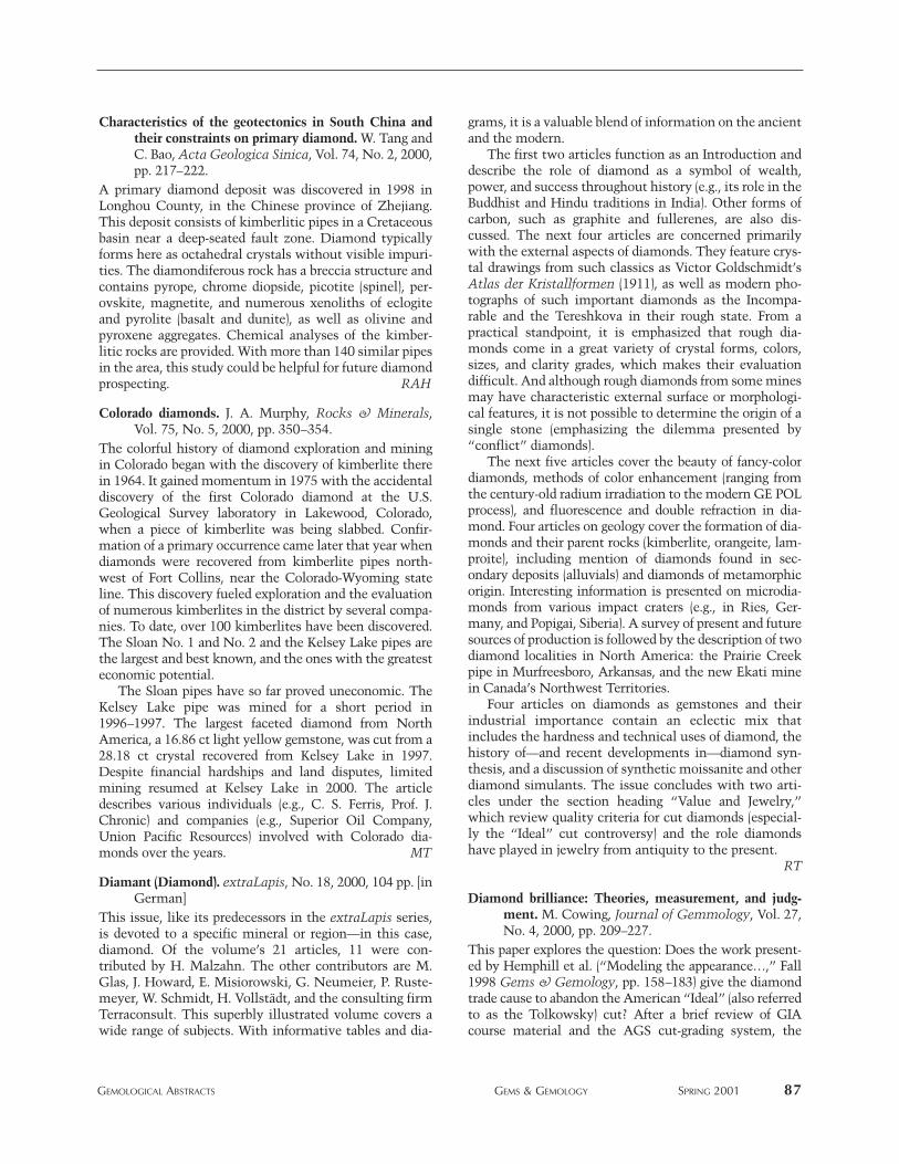
Characteristics of the geotectonics in South China andtheir constraints on primary diamond. W. Tang andC. Bao, Acta Geologica Sinica, Vol. 74, No. 2, 2000,pp. 217–222.
A primary diamond deposit was discovered in 1998 inLonghou County, in the Chinese province of Zhejiang.This deposit consists of kimberlitic pipes in a Cretaceousbasin near a deep-seated fault zone. Diamond typicallyforms here as octahedral crystals without visible impuri-ties. The diamondiferous rock has a breccia structure andcontains pyrope, chrome diopside, picotite (spinel), per-ovskite, magnetite, and numerous xenoliths of eclogiteand pyrolite (basalt and dunite), as well as olivine andpyroxene aggregates. Chemical analyses of the kimber-litic rocks are provided. With more than 140 similar pipesin the area, this study could be helpful for future diamondprospecting. RAH
Colorado diamonds. J. A. Murphy, Rocks & Minerals,Vol. 75, No. 5, 2000, pp. 350–354.
The colorful history of diamond exploration and miningin Colorado began with the discovery of kimberlite therein 1964. It gained momentum in 1975 with the accidentaldiscovery of the first Colorado diamond at the U.S.Geological Survey laboratory in Lakewood, Colorado,when a piece of kimberlite was being slabbed. Confir-mation of a primary occurrence came later that year whendiamonds were recovered from kimberlite pipes north-west of Fort Collins, near the Colorado-Wyoming stateline. This discovery fueled exploration and the evaluationof numerous kimberlites in the district by several compa-nies. To date, over 100 kimberlites have been discovered.The Sloan No. 1 and No. 2 and the Kelsey Lake pipes arethe largest and best known, and the ones with the greatesteconomic potential.
The Sloan pipes have so far proved uneconomic. TheKelsey Lake pipe was mined for a short period in1996–1997. The largest faceted diamond from NorthAmerica, a 16.86 ct light yellow gemstone, was cut from a28.18 ct crystal recovered from Kelsey Lake in 1997.Despite financial hardships and land disputes, limitedmining resumed at Kelsey Lake in 2000. The articledescribes various individuals (e.g., C. S. Ferris, Prof. J.Chronic) and companies (e.g., Superior Oil Company,Union Pacific Resources) involved with Colorado dia-monds over the years. MT
Diamant (Diamond). extraLapis, No. 18, 2000, 104 pp. [inGerman]
This issue, like its predecessors in the extraLapis series,is devoted to a specific mineral or region—in this case,diamond. Of the volume’s 21 articles, 11 were con-tributed by H. Malzahn. The other contributors are M.Glas, J. Howard, E. Misiorowski, G. Neumeier, P. Ruste-meyer, W. Schmidt, H. Vollstädt, and the consulting firmTerraconsult. This superbly illustrated volume covers awide range of subjects. With informative tables and dia-
grams, it is a valuable blend of information on the ancientand the modern.
The first two articles function as an Introduction anddescribe the role of diamond as a symbol of wealth,power, and success throughout history (e.g., its role in theBuddhist and Hindu traditions in India). Other forms ofcarbon, such as graphite and fullerenes, are also dis-cussed. The next four articles are concerned primarilywith the external aspects of diamonds. They feature crys-tal drawings from such classics as Victor Goldschmidt’sAtlas der Kristallformen (1911), as well as modern pho-tographs of such important diamonds as the Incompa-rable and the Tereshkova in their rough state. From apractical standpoint, it is emphasized that rough dia-monds come in a great variety of crystal forms, colors,sizes, and clarity grades, which makes their evaluationdifficult. And although rough diamonds from some minesmay have characteristic external surface or morphologi-cal features, it is not possible to determine the origin of asingle stone (emphasizing the dilemma presented by“conflict” diamonds).
The next five articles cover the beauty of fancy-colordiamonds, methods of color enhancement (ranging fromthe century-old radium irradiation to the modern GE POLprocess), and fluorescence and double refraction in dia-mond. Four articles on geology cover the formation of dia-monds and their parent rocks (kimberlite, orangeite, lam-proite), including mention of diamonds found in sec-ondary deposits (alluvials) and diamonds of metamorphicorigin. Interesting information is presented on microdia-monds from various impact craters (e.g., in Ries, Ger-many, and Popigai, Siberia). A survey of present and futuresources of production is followed by the description of twodiamond localities in North America: the Prairie Creekpipe in Murfreesboro, Arkansas, and the new Ekati minein Canada’s Northwest Territories.
Four articles on diamonds as gemstones and theirindustrial importance contain an eclectic mix thatincludes the hardness and technical uses of diamond, thehistory of—and recent developments in—diamond syn-thesis, and a discussion of synthetic moissanite and otherdiamond simulants. The issue concludes with two arti-cles under the section heading “Value and Jewelry,”which review quality criteria for cut diamonds (especial-ly the “Ideal” cut controversy) and the role diamondshave played in jewelry from antiquity to the present.
RT
Diamond brilliance: Theories, measurement, and judg-ment. M. Cowing, Journal of Gemmology, Vol. 27,No. 4, 2000, pp. 209–227.
This paper explores the question: Does the work present-ed by Hemphill et al. (“Modeling the appearance…,” Fall1998 Gems & Gemology, pp. 158–183) give the diamondtrade cause to abandon the American “Ideal” (also referredto as the Tolkowsky) cut? After a brief review of GIAcourse material and the AGS cut-grading system, the
GEMOLOGICAL ABSTRACTS GEMS & GEMOLOGY SPRING 2001 87
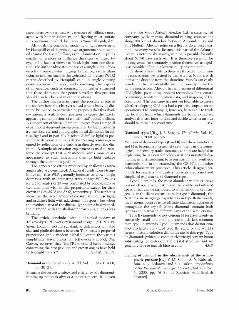
paper offers two premises: Any measure of brilliance mustagree with human judgment, and lighting must imitatethe conditions in which brilliance is “normally judged.”
Although the computer modeling of light movementby Hemphill et al. is praised, two arguments are present-ed against the use of diffuse, even illumination: It yieldssmaller differences in brilliance than can be judged byeye, and it lacks a viewer to block light from one direc-tion. The author advocates the use of a single view—fromdirectly overhead—for judging brilliance, rather thanusing an average, such as the weighted light return (WLR)metric described by Hemphill et al. A single viewingpoint is proposed for more clearly observing other aspectsof appearance, such as contrast. It is further suggestedthat those diamonds that perform well in this positionshould also be checked in other positions.
The author discusses in depth the possible effects ofthe shadow from the observer’s head when observing dia-mond brilliance. In particular, he proposes that this shad-ow interacts with a deep pavilion to cause the black-appearing center portions of a “nail-head” round brilliant.A comparison of virtual diamond images from Hemphillet al., model diamond images generated by GemCad witha close observer, and photographs of real diamonds (in dif-fuse light and in partially blackened diffuse light) is pre-sented to demonstrate that a dark-appearing center is gen-erated by reflections of a dark area directly over the dia-mond. A simple observation experiment is used to rein-force the concept that a “nail-head” owes more of itsappearance to such reflections than to light leakagethrough the diamond’s pavilion.
The appearance effects produced by shallower crownangles also are considered. A general result from Hemp-hill et al.—that WLR generally increases as crown angledecreases, with an interesting array of high WLR valuesfor crown angles of 23°—is contrasted by photographs oftwo diamonds with similar proportions except for theircrown angles (35.3° and 32.6°, respectively). These photosshow that the two diamonds look similar in diffuse light,and in diffuse light with additional “hot spots,” but whenthe overhead area of the diffuse light source is darkened,the diamond with the shallower crown angle looks lessbrilliant.
The article concludes with a historical review ofTolkowsky’s 1919 work (“Diamond design…,” E. & F. N.Spon, London), noting substantive differences in tablesize and girdle thickness between Tolkowsky’s proposedproportions and a modern “Ideal.” Despite the varioussimplifying assumptions of Tolkowsky’s model, Mr.Cowing observes that “his [Tolkowsky’s] basic findingsconcerning the best pavilion and crown angles have heldup for eighty years.” Ilene M. Reinitz
Diamond in the rough. GPS World, Vol. 11, No. 1, 2000,pp. 20–24.
Ensuring the security, safety, and efficiency of a diamond-mining operation is always a major concern. It is even
more so for South Africa’s Alexkor Ltd., a state-ownedcompany with marine diamond-mining concessionsalong 100 km of shoreline between Alexander Bay andPort Nolloth. Alexkor relies on a fleet of diver-based dia-mond recovery vessels. Because this part of the AtlanticOcean is notoriously stormy, mining is possible for onlyabout 60–90 days each year. It is therefore essential formining vessels to accurately position themselves as rapid-ly as possible, often in a low-visibility environment.
Offshore of South Africa there are three diamond-min-ing concessions, designated by the letters a, b, and c withincreasing distance from the shoreline. Vessels can easilywander, either accidentally or intentionally, into thewrong concession. Alexkor has implemented differentialGPS (global positioning system) technology for accuratepositioning, real-time location data, and mapping of theocean floor. The company has not yet been able to assesswhether adopting GPS has had a positive impact on itsoperations. The company is, however, better able to trackthe location from which diamonds are being extracted,analyze database information, and decide whether an areashould be mined a second time. MT
Diamond types I/IIab. J. E. Shigley, The Guide, Vol. 19,No. 4, 2000, pp. 8–9.
Mention of diamond types (I and II) and their varieties (aand b) is becoming increasingly prominent in the gemo-logical and jewelry trade literature, as they are helpful inexplaining the reasons for color variations in natural dia-monds, in distinguishing between natural and syntheticdiamonds, and in understanding the GE POL and othercolor-enhancement processes. This article, designed pri-marily for retailers and dealers, presents a succinct andsimplified explanation of diamond types.
Type I diamonds, the most abundant in nature, havecertain characteristic features in the visible and infraredspectra that can be attributed to small amounts of nitro-gen (N) in the diamond structure. In type Ia diamonds, theN atoms are in aggregates; whereas in type Ib diamonds,the N atoms occur as isolated, individual atoms dispersedthroughout the crystal. Many diamonds contain bothtype Ia and Ib areas in different parts of the same crystal.
Type II diamonds do not contain N (or have it only inextremely small amounts) and are much less commonthan type I diamonds. Type II diamonds that do not con-duct electricity are called type IIa; some of the world’slargest, historic colorless diamonds are of this type. TypeIIb diamonds (which do conduct electricity) contain boronsubstituting for carbon in the crystal structure and aregenerally blue or grayish blue in color. AMB
Etching of diamond in the silicate melt at the atmos-pheric pressure [sic]. V. M. Sonin, A. V. Naberuk-hina, E. N. Fedorova, and A. I. Turkin, Proceedingsof the Russian Mineralogical Society, Vol. 129, No.5, 2000, pp. 76–81 [in Russian with Englishabstract].
88 GEMOLOGICAL ABSTRACTS GEMS & GEMOLOGY SPRING 2001
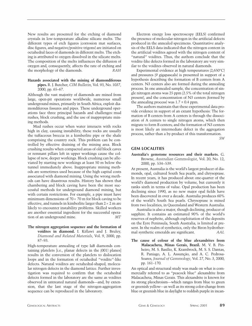
New results are presented for the etching of diamondcrystals in low-temperature alkaline silicate melts. Thedifferent types of etch figures (corrosion mat surfaces,disc figures, and negative/positive trigons) are initiated onoctahedral faces of diamonds in different melts. The etch-ing is attributed to oxygen dissolved in the silicate melts.The composition of the melts influences the diffusion ofoxygen and, consequently, affects the rate of etching andthe morphology of the diamonds. RAH
Hazards associated with the mining of diamondiferouspipes. R. J. Butcher, CIM Bulletin, Vol. 93, No. 1037,2000, pp. 65–67.
Although the vast majority of diamonds are mined fromlarge, open-pit operations worldwide, numerous smallunderground mines, primarily in South Africa, exploit dia-mondiferous fissures and pipes. These underground oper-ations face three principal hazards and challenges: mudrushes, block crushing, and the use of inappropriate min-ing methods.
Mud rushes occur when water interacts with rockshigh in clay, causing instability; these rocks are usuallythe tuffaceous breccia in a kimberlite pipe or the shalecomprising the country rock. This problem can be con-trolled by effective draining of the mining area. Blockcrushing results when compacted areas of old block cavesor remnant pillars left in upper workings cause the col-lapse of new, deeper workings. Block crushing can be alle-viated by starting new workings at least 50 m below thetunnel immediately above. Inappropriate mining meth-ods are sometimes used because of the high capital costsassociated with diamond mining. Using the wrong meth-ods can have disastrous results. History has shown thatchambering and block caving have been the most suc-cessful methods for underground diamond mining, butwith certain restrictions. For example, a pipe must haveminimum dimensions of 70 × 70 m for block caving to beeffective, and tunnels in kimberlite larger than 2 × 2 m arelikely to encounter instability problems. Skilled workersare another essential ingredient for the successful opera-tion of an underground mine. MT
The nitrogen aggregation sequence and the formation ofvoidites in diamond. I. Kiflawi and J. Bruley,Diamond and Related Materials, Vol. 9, 2000, pp.87–93.
High-temperature annealing of type IaB diamonds con-taining platelets [i.e., planar defects in the (001) planes]results in the conversion of the platelets to dislocationloops and in the formation of octahedral “voidite”-likedefects. Natural voidites are octahedral-shaped, molecu-lar nitrogen defects in the diamond lattice. Further inves-tigation was required to confirm that the octahedraldefects formed in the laboratory are the same as voiditesobserved in untreated natural diamonds—and, by exten-sion, that the last stage of the nitrogen-aggregationsequence can be reproduced in the laboratory.
Electron energy loss spectroscopy (EELS) confirmedthe presence of molecular nitrogen in the artificial defectsproduced in the annealed specimens. Quantitative analy-sis of the EELS data indicated that the nitrogen content inthe artificial voidites agreed with the nitrogen content of“natural” voidites. Thus, the authors conclude that thevoidite-like defects formed in the laboratory are very sim-ilar to the voidites observed in natural diamonds.
Experimental evidence at high temperatures (2,650°C)and pressures (9 gigapascals) is presented in support of ahypothesis describing the formation of B centers from Acenters. N3 centers also are formed during the annealingprocess. In one annealed sample, the concentration of sin-gle nitrogen atoms was 25 ppm (2.5% of the total nitrogenpresent), and the concentration of N3 centers (formed bythe annealing process) was 1.7 ± 0.4 ppm.
The authors maintain that these experimental data pro-vide evidence in support of an extant hypothesis: The for-mation of B centers from A centers is through the dissoci-ation of A centers to single nitrogen atoms, which thenmigrate to form B centers; and the formation of N3 centersis most likely an intermediate defect in the aggregationprocess, rather than a by-product of this transformation.
SW
GEM LOCALITIESAustralia’s gemstone resources and their markets. G.
Browne, Australian Gemmologist, Vol. 20, No. 12,2000, pp. 534–539.
At present, Australia is the world’s largest producer of dia-monds, opal, cultured South Sea pearls, and chrysoprase.In recent years, it has produced about one-quarter of theworld’s diamond production by volume, but currently itranks sixth in terms of value. Opal production has beendeclining since 1990, as no new major opal fields havebeen discovered in over a decade. Australia produces 60%of the world’s South Sea pearls. Chrysoprase is minedfrom two localities, in Queensland and Western Australia.
Australia is also a major, though declining, producer ofsapphire. It contains an estimated 90% of the world’sreserves of nephrite, although exploitation of the depositson the Eyre Peninsula, South Australia, is limited at pre-sent. In the realm of synthetics, only the Biron hydrother-mal synthetic emeralds are significant. AAL
The cause of colour of the blue alexandrites fromMalacacheta, Minas Gerais, Brazil. M. V. B. Pin-heiro, M. S. Basílio, K. Krambrock, M. S. S. Dantas,R. Paniago, A. L. Assunção, and A. C. Pedrosa-Soares, Journal of Gemmology, Vol. 27, No. 3, 2000,pp. 161–170.
An optical and structural study was made on what is com-mercially referred to as “peacock blue” alexandrite fromMalacacheta, Minas Gerais. This alexandrite is known forits strong pleochroism—which ranges from blue to greenor greenish yellow—as well as its strong color-change fromblue or greenish blue in daylight to reddish purple in incan-
GEMOLOGICAL ABSTRACTS GEMS & GEMOLOGY SPRING 2001 89
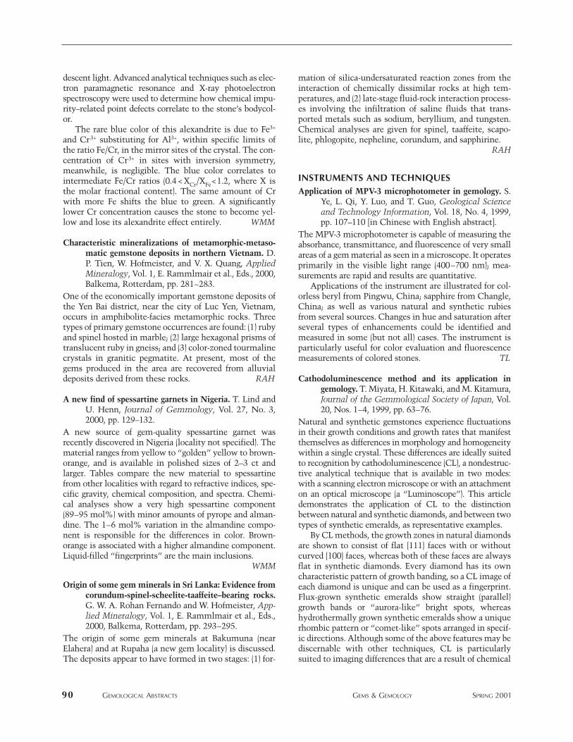
descent light. Advanced analytical techniques such as elec-tron paramagnetic resonance and X-ray photoelectronspectroscopy were used to determine how chemical impu-rity–related point defects correlate to the stone’s bodycol-or.
The rare blue color of this alexandrite is due to Fe3+
and Cr3+ substituting for Al3+, within specific limits ofthe ratio Fe/Cr, in the mirror sites of the crystal. The con-centration of Cr3+ in sites with inversion symmetry,meanwhile, is negligible. The blue color correlates tointermediate Fe/Cr ratios (0.4 < XCr/XFe<1.2, where X isthe molar fractional content). The same amount of Crwith more Fe shifts the blue to green. A significantlylower Cr concentration causes the stone to become yel-low and lose its alexandrite effect entirely. WMM
Characteristic mineralizations of metamorphic-metaso-matic gemstone deposits in northern Vietnam. D.P. Tien, W. Hofmeister, and V. X. Quang, AppliedMineralogy, Vol. 1, E. Rammlmair et al., Eds., 2000,Balkema, Rotterdam, pp. 281–283.
One of the economically important gemstone deposits ofthe Yen Bai district, near the city of Luc Yen, Vietnam,occurs in amphibolite-facies metamorphic rocks. Threetypes of primary gemstone occurrences are found: (1) rubyand spinel hosted in marble; (2) large hexagonal prisms oftranslucent ruby in gneiss; and (3) color-zoned tourmalinecrystals in granitic pegmatite. At present, most of thegems produced in the area are recovered from alluvialdeposits derived from these rocks. RAH
A new find of spessartine garnets in Nigeria. T. Lind andU. Henn, Journal of Gemmology, Vol. 27, No. 3,2000, pp. 129–132.
A new source of gem-quality spessartine garnet wasrecently discovered in Nigeria (locality not specified). Thematerial ranges from yellow to “golden” yellow to brown-orange, and is available in polished sizes of 2–3 ct andlarger. Tables compare the new material to spessartinefrom other localities with regard to refractive indices, spe-cific gravity, chemical composition, and spectra. Chemi-cal analyses show a very high spessartine component(89–95 mol%) with minor amounts of pyrope and alman-dine. The 1–6 mol% variation in the almandine compo-nent is responsible for the differences in color. Brown-orange is associated with a higher almandine component.Liquid-filled “fingerprints” are the main inclusions.
WMM
Origin of some gem minerals in Sri Lanka: Evidence fromcorundum-spinel-scheelite-taaffeite–bearing rocks.G. W. A. Rohan Fernando and W. Hofmeister, App-lied Mineralogy, Vol. 1, E. Rammlmair et al., Eds.,2000, Balkema, Rotterdam, pp. 293–295.
The origin of some gem minerals at Bakumuna (nearElahera) and at Rupaha (a new gem locality) is discussed.The deposits appear to have formed in two stages: (1) for-
mation of silica-undersaturated reaction zones from theinteraction of chemically dissimilar rocks at high tem-peratures, and (2) late-stage fluid-rock interaction process-es involving the infiltration of saline fluids that trans-ported metals such as sodium, beryllium, and tungsten.Chemical analyses are given for spinel, taaffeite, scapo-lite, phlogopite, nepheline, corundum, and sapphirine.
RAH
INSTRUMENTS AND TECHNIQUESApplication of MPV-3 microphotometer in gemology. S.
Ye, L. Qi, Y. Luo, and T. Guo, Geological Scienceand Technology Information, Vol. 18, No. 4, 1999,pp. 107–110 [in Chinese with English abstract].
The MPV-3 microphotometer is capable of measuring theabsorbance, transmittance, and fluorescence of very smallareas of a gem material as seen in a microscope. It operatesprimarily in the visible light range (400–700 nm); mea-surements are rapid and results are quantitative.
Applications of the instrument are illustrated for col-orless beryl from Pingwu, China; sapphire from Changle,China; as well as various natural and synthetic rubiesfrom several sources. Changes in hue and saturation afterseveral types of enhancements could be identified andmeasured in some (but not all) cases. The instrument isparticularly useful for color evaluation and fluorescencemeasurements of colored stones. TL
Cathodoluminescence method and its application ingemology. T. Miyata, H. Kitawaki, and M. Kitamura,Journal of the Gemmological Society of Japan, Vol.20, Nos. 1–4, 1999, pp. 63–76.
Natural and synthetic gemstones experience fluctuationsin their growth conditions and growth rates that manifestthemselves as differences in morphology and homogeneitywithin a single crystal. These differences are ideally suitedto recognition by cathodoluminescence (CL), a nondestruc-tive analytical technique that is available in two modes:with a scanning electron microscope or with an attachmenton an optical microscope (a “Luminoscope”). This articledemonstrates the application of CL to the distinctionbetween natural and synthetic diamonds, and between twotypes of synthetic emeralds, as representative examples.
By CL methods, the growth zones in natural diamondsare shown to consist of flat {111} faces with or withoutcurved {100} faces, whereas both of these faces are alwaysflat in synthetic diamonds. Every diamond has its owncharacteristic pattern of growth banding, so a CL image ofeach diamond is unique and can be used as a fingerprint.Flux-grown synthetic emeralds show straight (parallel)growth bands or “aurora-like” bright spots, whereashydrothermally grown synthetic emeralds show a uniquerhombic pattern or “comet-like” spots arranged in specif-ic directions. Although some of the above features may bediscernable with other techniques, CL is particularlysuited to imaging differences that are a result of chemical
90 GEMOLOGICAL ABSTRACTS GEMS & GEMOLOGY SPRING 2001
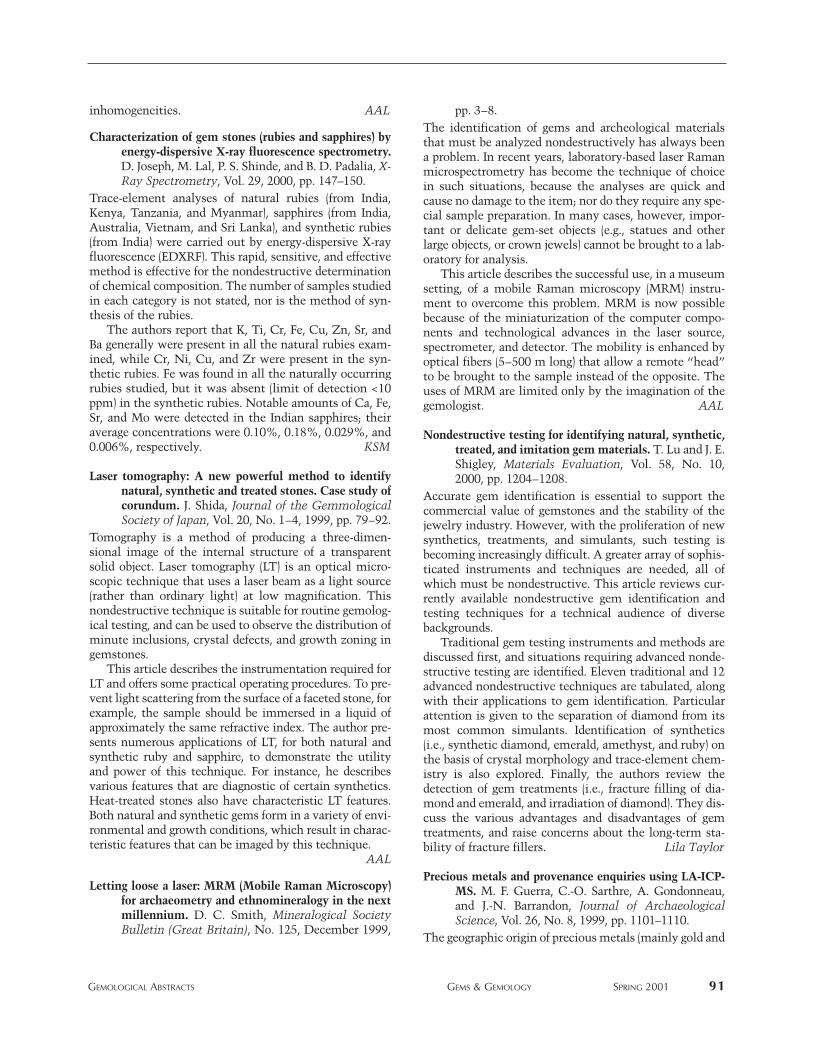
inhomogeneities. AAL
Characterization of gem stones (rubies and sapphires) byenergy-dispersive X-ray fluorescence spectrometry.D. Joseph, M. Lal, P. S. Shinde, and B. D. Padalia, X-Ray Spectrometry, Vol. 29, 2000, pp. 147–150.
Trace-element analyses of natural rubies (from India,Kenya, Tanzania, and Myanmar), sapphires (from India,Australia, Vietnam, and Sri Lanka), and synthetic rubies(from India) were carried out by energy-dispersive X-rayfluorescence (EDXRF). This rapid, sensitive, and effectivemethod is effective for the nondestructive determinationof chemical composition. The number of samples studiedin each category is not stated, nor is the method of syn-thesis of the rubies.
The authors report that K, Ti, Cr, Fe, Cu, Zn, Sr, andBa generally were present in all the natural rubies exam-ined, while Cr, Ni, Cu, and Zr were present in the syn-thetic rubies. Fe was found in all the naturally occurringrubies studied, but it was absent (limit of detection <10ppm) in the synthetic rubies. Notable amounts of Ca, Fe,Sr, and Mo were detected in the Indian sapphires; theiraverage concentrations were 0.10%, 0.18%, 0.029%, and0.006%, respectively. KSM
Laser tomography: A new powerful method to identifynatural, synthetic and treated stones. Case study ofcorundum. J. Shida, Journal of the GemmologicalSociety of Japan, Vol. 20, No. 1–4, 1999, pp. 79–92.
Tomography is a method of producing a three-dimen-sional image of the internal structure of a transparentsolid object. Laser tomography (LT) is an optical micro-scopic technique that uses a laser beam as a light source(rather than ordinary light) at low magnification. Thisnondestructive technique is suitable for routine gemolog-ical testing, and can be used to observe the distribution ofminute inclusions, crystal defects, and growth zoning ingemstones.
This article describes the instrumentation required forLT and offers some practical operating procedures. To pre-vent light scattering from the surface of a faceted stone, forexample, the sample should be immersed in a liquid ofapproximately the same refractive index. The author pre-sents numerous applications of LT, for both natural andsynthetic ruby and sapphire, to demonstrate the utilityand power of this technique. For instance, he describesvarious features that are diagnostic of certain synthetics.Heat-treated stones also have characteristic LT features.Both natural and synthetic gems form in a variety of envi-ronmental and growth conditions, which result in charac-teristic features that can be imaged by this technique.
AAL
Letting loose a laser: MRM (Mobile Raman Microscopy)for archaeometry and ethnomineralogy in the nextmillennium. D. C. Smith, Mineralogical SocietyBulletin (Great Britain), No. 125, December 1999,
pp. 3–8.The identification of gems and archeological materialsthat must be analyzed nondestructively has always beena problem. In recent years, laboratory-based laser Ramanmicrospectrometry has become the technique of choicein such situations, because the analyses are quick andcause no damage to the item; nor do they require any spe-cial sample preparation. In many cases, however, impor-tant or delicate gem-set objects (e.g., statues and otherlarge objects, or crown jewels) cannot be brought to a lab-oratory for analysis.
This article describes the successful use, in a museumsetting, of a mobile Raman microscopy (MRM) instru-ment to overcome this problem. MRM is now possiblebecause of the miniaturization of the computer compo-nents and technological advances in the laser source,spectrometer, and detector. The mobility is enhanced byoptical fibers (5–500 m long) that allow a remote “head”to be brought to the sample instead of the opposite. Theuses of MRM are limited only by the imagination of thegemologist. AAL
Nondestructive testing for identifying natural, synthetic,treated, and imitation gem materials. T. Lu and J. E.Shigley, Materials Evaluation, Vol. 58, No. 10,2000, pp. 1204–1208.
Accurate gem identification is essential to support thecommercial value of gemstones and the stability of thejewelry industry. However, with the proliferation of newsynthetics, treatments, and simulants, such testing isbecoming increasingly difficult. A greater array of sophis-ticated instruments and techniques are needed, all ofwhich must be nondestructive. This article reviews cur-rently available nondestructive gem identification andtesting techniques for a technical audience of diversebackgrounds.
Traditional gem testing instruments and methods arediscussed first, and situations requiring advanced nonde-structive testing are identified. Eleven traditional and 12advanced nondestructive techniques are tabulated, alongwith their applications to gem identification. Particularattention is given to the separation of diamond from itsmost common simulants. Identification of synthetics(i.e., synthetic diamond, emerald, amethyst, and ruby) onthe basis of crystal morphology and trace-element chem-istry is also explored. Finally, the authors review thedetection of gem treatments (i.e., fracture filling of dia-mond and emerald, and irradiation of diamond). They dis-cuss the various advantages and disadvantages of gemtreatments, and raise concerns about the long-term sta-bility of fracture fillers. Lila Taylor
Precious metals and provenance enquiries using LA-ICP-MS. M. F. Guerra, C.-O. Sarthre, A. Gondonneau,and J.-N. Barrandon, Journal of ArchaeologicalScience, Vol. 26, No. 8, 1999, pp. 1101–1110.
The geographic origin of precious metals (mainly gold and
GEMOLOGICAL ABSTRACTS GEMS & GEMOLOGY SPRING 2001 91
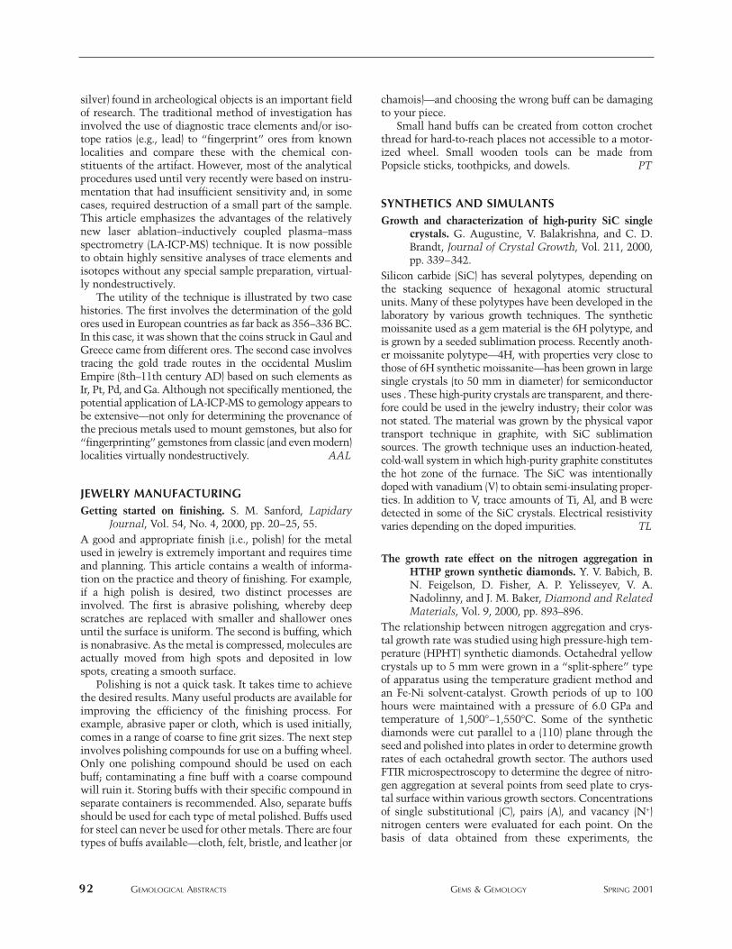
silver) found in archeological objects is an important fieldof research. The traditional method of investigation hasinvolved the use of diagnostic trace elements and/or iso-tope ratios (e.g., lead) to “fingerprint” ores from knownlocalities and compare these with the chemical con-stituents of the artifact. However, most of the analyticalprocedures used until very recently were based on instru-mentation that had insufficient sensitivity and, in somecases, required destruction of a small part of the sample.This article emphasizes the advantages of the relativelynew laser ablation–inductively coupled plasma–massspectrometry (LA-ICP-MS) technique. It is now possibleto obtain highly sensitive analyses of trace elements andisotopes without any special sample preparation, virtual-ly nondestructively.
The utility of the technique is illustrated by two casehistories. The first involves the determination of the goldores used in European countries as far back as 356–336 BC.In this case, it was shown that the coins struck in Gaul andGreece came from different ores. The second case involvestracing the gold trade routes in the occidental MuslimEmpire (8th–11th century AD) based on such elements asIr, Pt, Pd, and Ga. Although not specifically mentioned, thepotential application of LA-ICP-MS to gemology appears tobe extensive—not only for determining the provenance ofthe precious metals used to mount gemstones, but also for“fingerprinting” gemstones from classic (and even modern)localities virtually nondestructively. AAL
JEWELRY MANUFACTURINGGetting started on finishing. S. M. Sanford, Lapidary
Journal, Vol. 54, No. 4, 2000, pp. 20–25, 55.A good and appropriate finish (i.e., polish) for the metalused in jewelry is extremely important and requires timeand planning. This article contains a wealth of informa-tion on the practice and theory of finishing. For example,if a high polish is desired, two distinct processes areinvolved. The first is abrasive polishing, whereby deepscratches are replaced with smaller and shallower onesuntil the surface is uniform. The second is buffing, whichis nonabrasive. As the metal is compressed, molecules areactually moved from high spots and deposited in lowspots, creating a smooth surface.
Polishing is not a quick task. It takes time to achievethe desired results. Many useful products are available forimproving the efficiency of the finishing process. Forexample, abrasive paper or cloth, which is used initially,comes in a range of coarse to fine grit sizes. The next stepinvolves polishing compounds for use on a buffing wheel.Only one polishing compound should be used on eachbuff; contaminating a fine buff with a coarse compoundwill ruin it. Storing buffs with their specific compound inseparate containers is recommended. Also, separate buffsshould be used for each type of metal polished. Buffs usedfor steel can never be used for other metals. There are fourtypes of buffs available—cloth, felt, bristle, and leather (or
chamois)—and choosing the wrong buff can be damagingto your piece.
Small hand buffs can be created from cotton crochetthread for hard-to-reach places not accessible to a motor-ized wheel. Small wooden tools can be made fromPopsicle sticks, toothpicks, and dowels. PT
SYNTHETICS AND SIMULANTSGrowth and characterization of high-purity SiC single
crystals. G. Augustine, V. Balakrishna, and C. D.Brandt, Journal of Crystal Growth, Vol. 211, 2000,pp. 339–342.
Silicon carbide (SiC) has several polytypes, depending onthe stacking sequence of hexagonal atomic structuralunits. Many of these polytypes have been developed in thelaboratory by various growth techniques. The syntheticmoissanite used as a gem material is the 6H polytype, andis grown by a seeded sublimation process. Recently anoth-er moissanite polytype—4H, with properties very close tothose of 6H synthetic moissanite—has been grown in largesingle crystals (to 50 mm in diameter) for semiconductoruses . These high-purity crystals are transparent, and there-fore could be used in the jewelry industry; their color wasnot stated. The material was grown by the physical vaportransport technique in graphite, with SiC sublimationsources. The growth technique uses an induction-heated,cold-wall system in which high-purity graphite constitutesthe hot zone of the furnace. The SiC was intentionallydoped with vanadium (V) to obtain semi-insulating proper-ties. In addition to V, trace amounts of Ti, Al, and B weredetected in some of the SiC crystals. Electrical resistivityvaries depending on the doped impurities. TL
The growth rate effect on the nitrogen aggregation inHTHP grown synthetic diamonds. Y. V. Babich, B.N. Feigelson, D. Fisher, A. P. Yelisseyev, V. A.Nadolinny, and J. M. Baker, Diamond and RelatedMaterials, Vol. 9, 2000, pp. 893–896.
The relationship between nitrogen aggregation and crys-tal growth rate was studied using high pressure-high tem-perature (HPHT) synthetic diamonds. Octahedral yellowcrystals up to 5 mm were grown in a “split-sphere” typeof apparatus using the temperature gradient method andan Fe-Ni solvent-catalyst. Growth periods of up to 100hours were maintained with a pressure of 6.0 GPa andtemperature of 1,500°–1,550°C. Some of the syntheticdiamonds were cut parallel to a (110) plane through theseed and polished into plates in order to determine growthrates of each octahedral growth sector. The authors usedFTIR microspectroscopy to determine the degree of nitro-gen aggregation at several points from seed plate to crys-tal surface within various growth sectors. Concentrationsof single substitutional (C), pairs (A), and vacancy (N+)nitrogen centers were evaluated for each point. On thebasis of data obtained from these experiments, the
92 GEMOLOGICAL ABSTRACTS GEMS & GEMOLOGY SPRING 2001
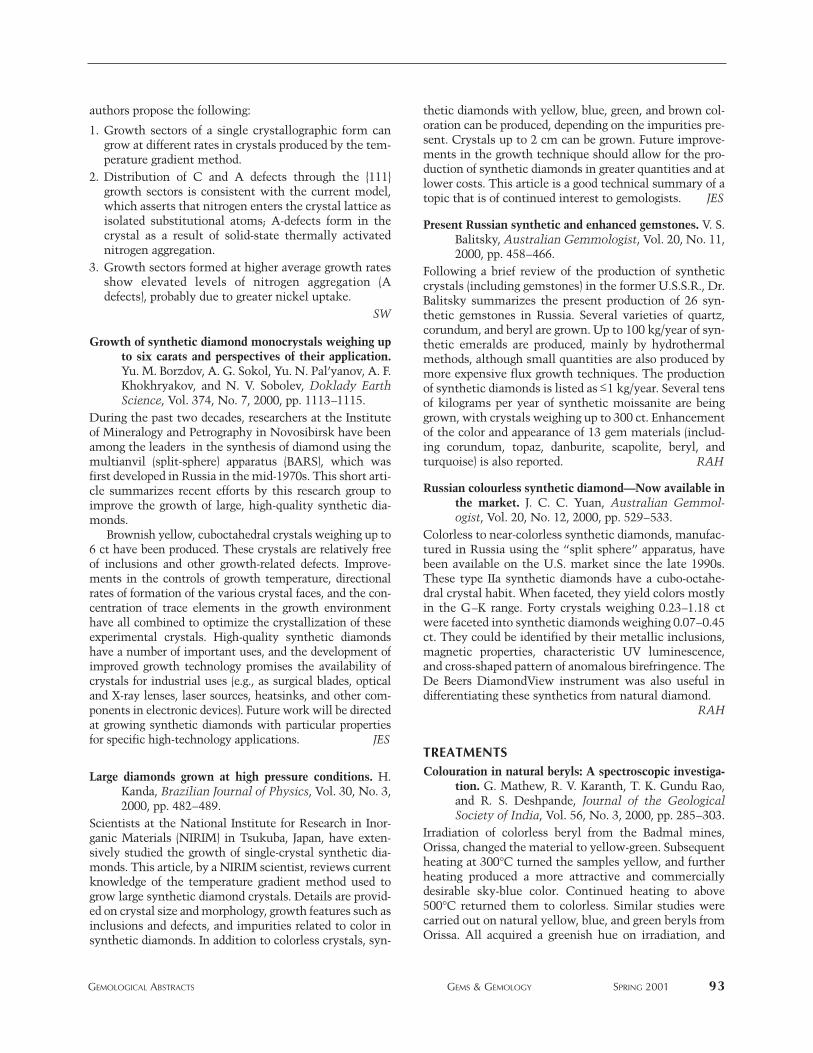
authors propose the following:
1. Growth sectors of a single crystallographic form cangrow at different rates in crystals produced by the tem-perature gradient method.
2. Distribution of C and A defects through the {111}growth sectors is consistent with the current model,which asserts that nitrogen enters the crystal lattice asisolated substitutional atoms; A-defects form in thecrystal as a result of solid-state thermally activatednitrogen aggregation.
3. Growth sectors formed at higher average growth ratesshow elevated levels of nitrogen aggregation (Adefects), probably due to greater nickel uptake.
SW
Growth of synthetic diamond monocrystals weighing upto six carats and perspectives of their application.Yu. M. Borzdov, A. G. Sokol, Yu. N. Pal’yanov, A. F.Khokhryakov, and N. V. Sobolev, Doklady EarthScience, Vol. 374, No. 7, 2000, pp. 1113–1115.
During the past two decades, researchers at the Instituteof Mineralogy and Petrography in Novosibirsk have beenamong the leaders in the synthesis of diamond using themultianvil (split-sphere) apparatus (BARS), which wasfirst developed in Russia in the mid-1970s. This short arti-cle summarizes recent efforts by this research group toimprove the growth of large, high-quality synthetic dia-monds.
Brownish yellow, cuboctahedral crystals weighing up to6 ct have been produced. These crystals are relatively freeof inclusions and other growth-related defects. Improve-ments in the controls of growth temperature, directionalrates of formation of the various crystal faces, and the con-centration of trace elements in the growth environmenthave all combined to optimize the crystallization of theseexperimental crystals. High-quality synthetic diamondshave a number of important uses, and the development ofimproved growth technology promises the availability ofcrystals for industrial uses (e.g., as surgical blades, opticaland X-ray lenses, laser sources, heatsinks, and other com-ponents in electronic devices). Future work will be directedat growing synthetic diamonds with particular propertiesfor specific high-technology applications. JES
Large diamonds grown at high pressure conditions. H.Kanda, Brazilian Journal of Physics, Vol. 30, No. 3,2000, pp. 482–489.
Scientists at the National Institute for Research in Inor-ganic Materials (NIRIM) in Tsukuba, Japan, have exten-sively studied the growth of single-crystal synthetic dia-monds. This article, by a NIRIM scientist, reviews currentknowledge of the temperature gradient method used togrow large synthetic diamond crystals. Details are provid-ed on crystal size and morphology, growth features such asinclusions and defects, and impurities related to color insynthetic diamonds. In addition to colorless crystals, syn-
thetic diamonds with yellow, blue, green, and brown col-oration can be produced, depending on the impurities pre-sent. Crystals up to 2 cm can be grown. Future improve-ments in the growth technique should allow for the pro-duction of synthetic diamonds in greater quantities and atlower costs. This article is a good technical summary of atopic that is of continued interest to gemologists. JES
Present Russian synthetic and enhanced gemstones. V. S.Balitsky, Australian Gemmologist, Vol. 20, No. 11,2000, pp. 458–466.
Following a brief review of the production of syntheticcrystals (including gemstones) in the former U.S.S.R., Dr.Balitsky summarizes the present production of 26 syn-thetic gemstones in Russia. Several varieties of quartz,corundum, and beryl are grown. Up to 100 kg/year of syn-thetic emeralds are produced, mainly by hydrothermalmethods, although small quantities are also produced bymore expensive flux growth techniques. The productionof synthetic diamonds is listed as ≤1 kg/year. Several tensof kilograms per year of synthetic moissanite are beinggrown, with crystals weighing up to 300 ct. Enhancementof the color and appearance of 13 gem materials (includ-ing corundum, topaz, danburite, scapolite, beryl, andturquoise) is also reported. RAH
Russian colourless synthetic diamond—Now available inthe market. J. C. C. Yuan, Australian Gemmol-ogist, Vol. 20, No. 12, 2000, pp. 529–533.
Colorless to near-colorless synthetic diamonds, manufac-tured in Russia using the “split sphere” apparatus, havebeen available on the U.S. market since the late 1990s.These type IIa synthetic diamonds have a cubo-octahe-dral crystal habit. When faceted, they yield colors mostlyin the G–K range. Forty crystals weighing 0.23–1.18 ctwere faceted into synthetic diamonds weighing 0.07–0.45ct. They could be identified by their metallic inclusions,magnetic properties, characteristic UV luminescence,and cross-shaped pattern of anomalous birefringence. TheDe Beers DiamondView instrument was also useful indifferentiating these synthetics from natural diamond.
RAH
TREATMENTSColouration in natural beryls: A spectroscopic investiga-
tion. G. Mathew, R. V. Karanth, T. K. Gundu Rao,and R. S. Deshpande, Journal of the GeologicalSociety of India, Vol. 56, No. 3, 2000, pp. 285–303.
Irradiation of colorless beryl from the Badmal mines,Orissa, changed the material to yellow-green. Subsequentheating at 300°C turned the samples yellow, and furtherheating produced a more attractive and commerciallydesirable sky-blue color. Continued heating to above500°C returned them to colorless. Similar studies werecarried out on natural yellow, blue, and green beryls fromOrissa. All acquired a greenish hue on irradiation, and
GEMOLOGICAL ABSTRACTS GEMS & GEMOLOGY SPRING 2001 93
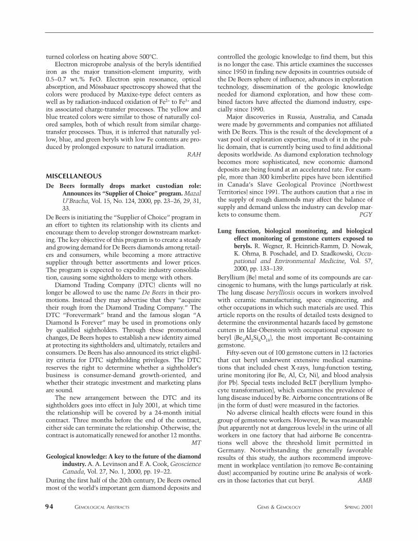
turned colorless on heating above 500°C.Electron microprobe analysis of the beryls identified
iron as the major transition-element impurity, with0.5–0.7 wt.% FeO. Electron spin resonance, opticalabsorption, and Mössbauer spectroscopy showed that thecolors were produced by Maxixe-type defect centers aswell as by radiation-induced oxidation of Fe2+ to Fe3+ andits associated charge-transfer processes. The yellow andblue treated colors were similar to those of naturally col-ored samples, both of which result from similar charge-transfer processes. Thus, it is inferred that naturally yel-low, blue, and green beryls with low Fe contents are pro-duced by prolonged exposure to natural irradiation.
RAH
MISCELLANEOUSDe Beers formally drops market custodian role:
Announces its “Supplier of Choice” program. MazalU’Bracha, Vol. 15, No. 124, 2000, pp. 23–26, 29, 31,33.
De Beers is initiating the “Supplier of Choice” program inan effort to tighten its relationship with its clients andencourage them to develop stronger downstream market-ing. The key objective of this program is to create a steadyand growing demand for De Beers diamonds among retail-ers and consumers, while becoming a more attractivesupplier through better assortments and lower prices.The program is expected to expedite industry consolida-tion, causing some sightholders to merge with others.
Diamond Trading Company (DTC) clients will nolonger be allowed to use the name De Beers in their pro-motions. Instead they may advertise that they “acquiretheir rough from the Diamond Trading Company.” TheDTC “Forevermark” brand and the famous slogan “ADiamond Is Forever” may be used in promotions onlyby qualified sightholders. Through these promotionalchanges, De Beers hopes to establish a new identity aimedat protecting its sightholders and, ultimately, retailers andconsumers. De Beers has also announced its strict eligibil-ity criteria for DTC sightholding privileges. The DTCreserves the right to determine whether a sightholder’sbusiness is consumer-demand growth-oriented, andwhether their strategic investment and marketing plansare sound.
The new arrangement between the DTC and itssightholders goes into effect in July 2001, at which timethe relationship will be covered by a 24-month initialcontract. Three months before the end of the contract,either side can terminate the relationship. Otherwise, thecontract is automatically renewed for another 12 months.
MT
Geological knowledge: A key to the future of the diamondindustry. A. A. Levinson and F. A. Cook, GeoscienceCanada, Vol. 27, No. 1, 2000, pp. 19–22.
During the first half of the 20th century, De Beers ownedmost of the world’s important gem diamond deposits and
controlled the geologic knowledge to find them, but thisis no longer the case. This article examines the successessince 1950 in finding new deposits in countries outside ofthe De Beers sphere of influence, advances in explorationtechnology, dissemination of the geologic knowledgeneeded for diamond exploration, and how these com-bined factors have affected the diamond industry, espe-cially since 1990.
Major discoveries in Russia, Australia, and Canadawere made by governments and companies not affiliatedwith De Beers. This is the result of the development of avast pool of exploration expertise, much of it in the pub-lic domain, that is currently being used to find additionaldeposits worldwide. As diamond exploration technologybecomes more sophisticated, new economic diamonddeposits are being found at an accelerated rate. For exam-ple, more than 300 kimberlite pipes have been identifiedin Canada’s Slave Geological Province (NorthwestTerritories) since 1991. The authors caution that a rise inthe supply of rough diamonds may affect the balance ofsupply and demand unless the industry can develop mar-kets to consume them. PGY
Lung function, biological monitoring, and biologicaleffect monitoring of gemstone cutters exposed toberyls. R. Wegner, R. Heinrich-Ramm, D. Nowak,K. Ohma, B. Poschadel, and D. Szadkowski, Occu-pational and Environmental Medicine, Vol. 57,2000, pp. 133–139.
Beryllium (Be) metal and some of its compounds are car-cinogenic to humans, with the lungs particularly at risk.The lung disease berylliosis occurs in workers involvedwith ceramic manufacturing, space engineering, andother occupations in which such materials are used. Thisarticle reports on the results of detailed tests designed todetermine the environmental hazards faced by gemstonecutters in Idar-Oberstein with occupational exposure toberyl (Be3Al2Si6O18), the most important Be-containinggemstone.
Fifty-seven out of 100 gemstone cutters in 12 factoriesthat cut beryl underwent extensive medical examina-tions that included chest X-rays, lung-function testing,urine monitoring (for Be, Al, Cr, Ni), and blood analysis(for Pb). Special tests included BeLT (beryllium lympho-cyte transformation), which examines the prevalence oflung disease induced by Be. Airborne concentrations of Be(in the form of dust) were measured in the factories.
No adverse clinical health effects were found in thisgroup of gemstone workers. However, Be was measurable(but apparently not at dangerous levels) in the urine of allworkers in one factory that had airborne Be concentra-tions well above the threshold limit permitted inGermany. Notwithstanding the generally favorableresults of this study, the authors recommend improve-ment in workplace ventilation (to remove Be-containingdust) accompanied by routine urine Be analysis of work-ers in those factories that cut beryl. AMB
94 GEMOLOGICAL ABSTRACTS GEMS & GEMOLOGY SPRING 2001