Spread Spectrum · Using spread spectrum from the beginning may hide an excessive jitter or...
48
Spread Spectrum For Power Supplies Speaker: Christian Kueck May 2019
Transcript of Spread Spectrum · Using spread spectrum from the beginning may hide an excessive jitter or...
Spread SpectrumFor Power Supplies
Speaker: Christian Kueck
May 2019

• Senior FAE supporting automotive Tier-1 customers throughout Germany
• Over two decades of experience managing EMI challenges
• Deeply involved in the definition and compliance testing of our leading AEC-Q100 power management solutions
• 22 years at Linear Technology
o Strategic Marketing Manager for Europe – Product definition and product support for PSU and LED circuits
o Field Application Engineer
• Additional:
o Design Engineer, Quality Assurance, Materials Engineer
• Microelectronics. Dipl. Ing., Elektrotechnik University of Dortmund
Speaker Intro: Christian Kueck
Agenda
The Motivation
PSU Fixed Frequency Spectrum
Effect of Switching Frequency and Duty Cycle on EMI
What Can Spread Spectrum Accomplish
Effective Methods to Make Spread Spectrum
Frequently Asked Questions About Spread Spectrum
Open Q&A
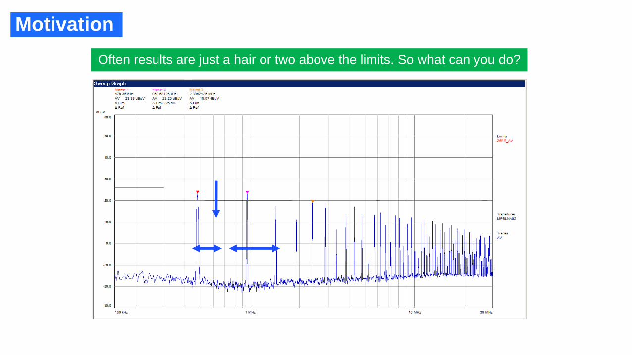
Motivation
Often results are just a hair or two above the limits. So what can you do?
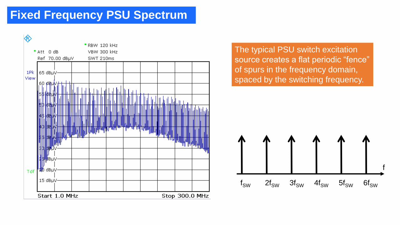
Fixed Frequency PSU Spectrum
The typical PSU switch excitation
source creates a flat periodic “fence”
of spurs in the frequency domain,
spaced by the switching frequency.
f
fSW 2fSW 3fSW 4fSW 5fSW 6fSW
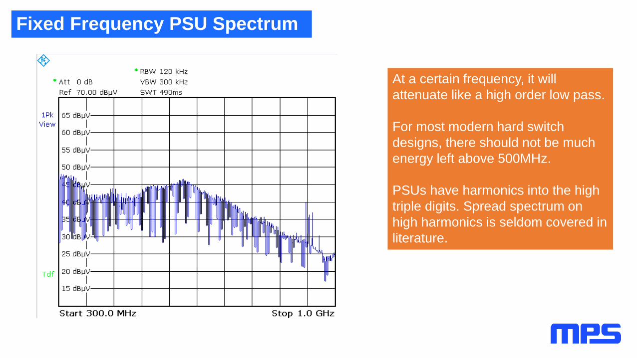
Fixed Frequency PSU Spectrum
At a certain frequency, it will
attenuate like a high order low pass.
For most modern hard switch
designs, there should not be much
energy left above 500MHz.
PSUs have harmonics into the high
triple digits. Spread spectrum on
high harmonics is seldom covered in
literature.

How Does Duty Cycle Affect the Lower Harmonics?
[08]
5dB/div
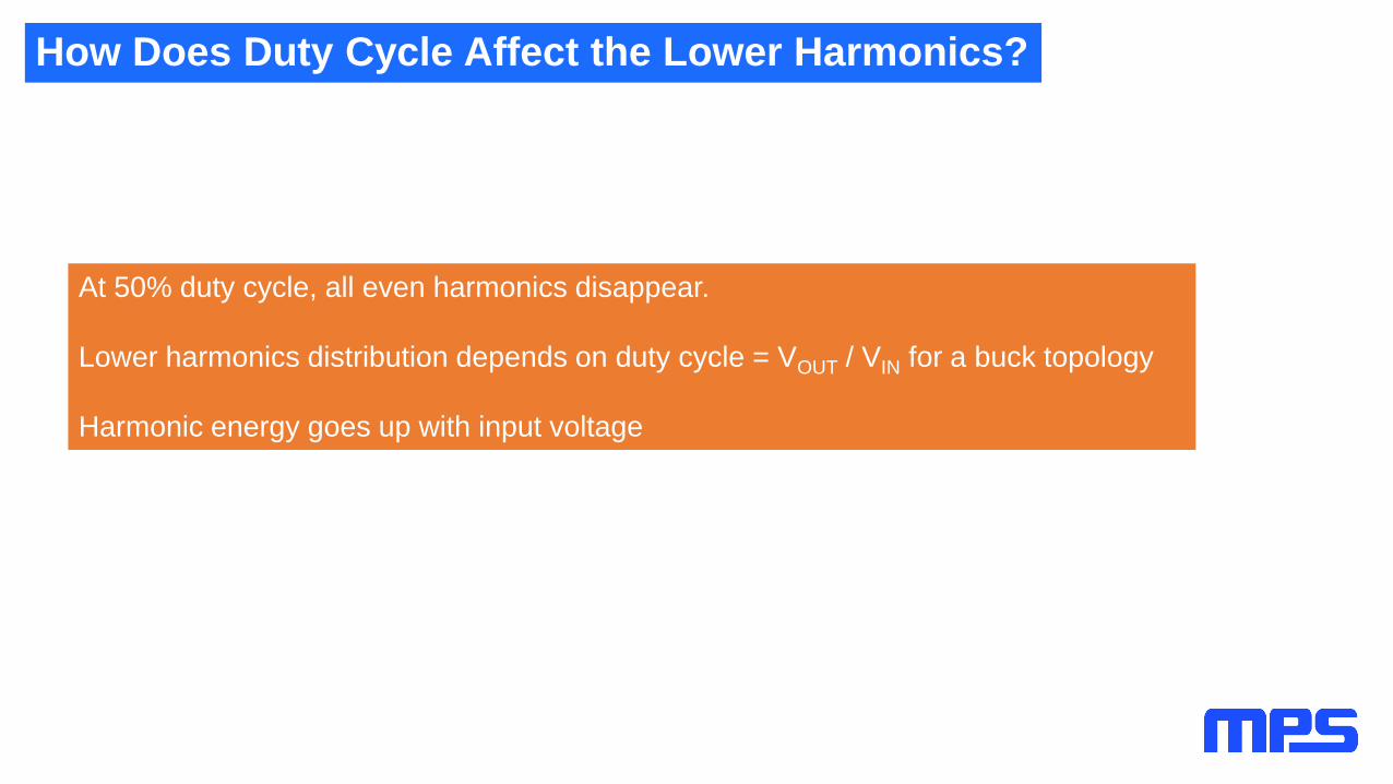
How Does Duty Cycle Affect the Lower Harmonics?
At 50% duty cycle, all even harmonics disappear.
Lower harmonics distribution depends on duty cycle = VOUT / VIN for a buck topology
Harmonic energy goes up with input voltage
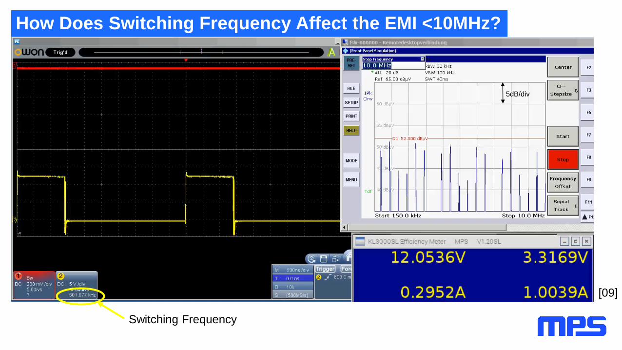
How Does Switching Frequency Affect the EMI <10MHz?
[09]
Switching Frequency
5dB/div
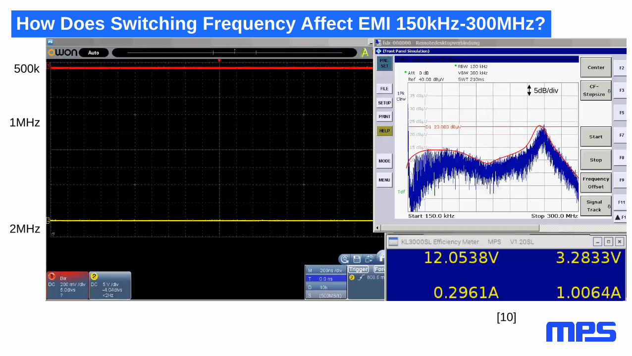
How Does Switching Frequency Affect EMI 150kHz-300MHz?
500k
1MHz
2MHz
[10]
5dB/div

RBW – Resolution Bandwidth Filter
EMI Receiver According to CISPR 16-1-1
http://www.schwarzbeck.de/appnotes/EMIRcvrCISPR16.pdf
Pk, QP or AV Filter

EMI Receiver Spectral View
The RBW filter moves with constant velocity (frequency change) through the receiver span from
Freq start to Freq stop. This is a convolution operation in the frequency domain.
f
fSW 2fSW 3fSW 4fSW 5fSW 6fSW
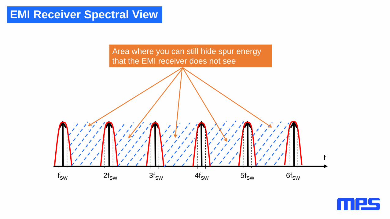
EMI Receiver Spectral View
Area where you can still hide spur energy
that the EMI receiver does not see
f
fSW 2fSW 3fSW 4fSW 5fSW 6fSW
EMI Receiver Spectral View
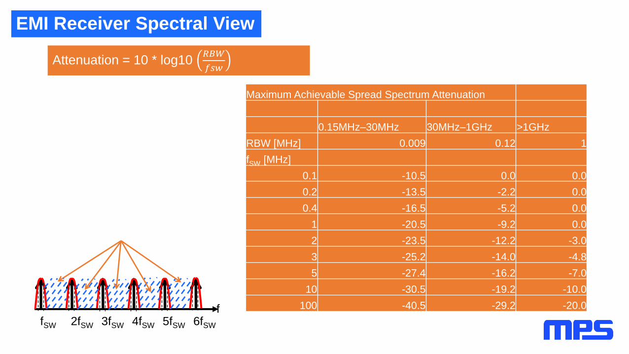
Attenuation = 10 * log10 𝑅𝐵𝑊
𝑓𝑠𝑤
ffSW 2fSW 3fSW 4fSW 5fSW 6fSW
Maximum Achievable Spread Spectrum Attenuation
0.15MHz–30MHz 30MHz–1GHz >1GHz
RBW [MHz] 0.009 0.12 1
fSW [MHz]
0.1 -10.5 0.0 0.0
0.2 -13.5 -2.2 0.0
0.4 -16.5 -5.2 0.0
1 -20.5 -9.2 0.0
2 -23.5 -12.2 -3.0
3 -25.2 -14.0 -4.8
5 -27.4 -16.2 -7.0
10 -30.5 -19.2 -10.0
100 -40.5 -29.2 -20.0

RBW Filter Time Domain View of Spur in the Frequency Domain
If the carrier stays longer than the bandpass impulse response time 1
𝑅𝐵𝑊inside the passband,
there will be no attenuation through the RBW filter, and you see the spurs’ original energy.
1
9𝑘𝐻𝑧= 111µ𝑠
1
120𝑘𝐻𝑧= 8.33µs
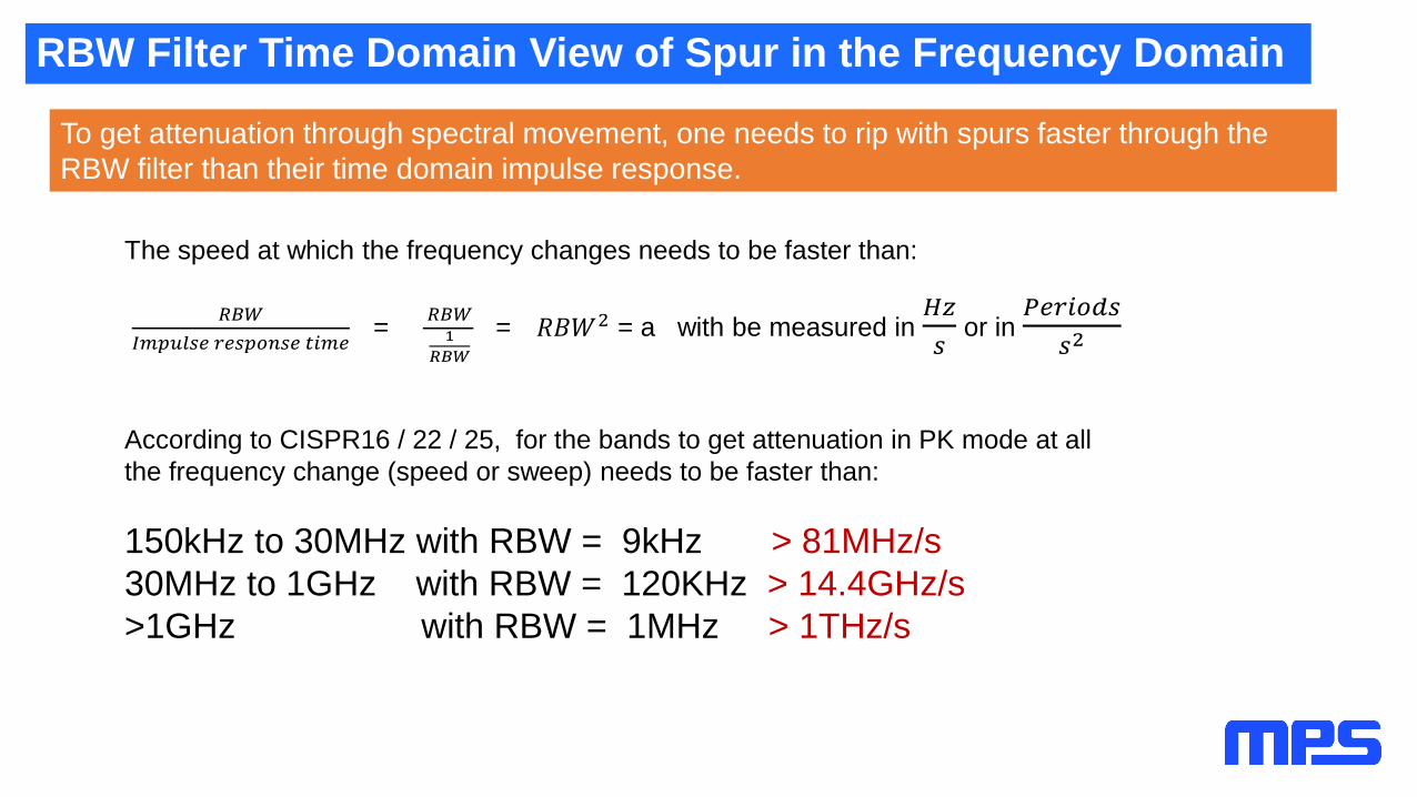
RBW Filter Time Domain View of Spur in the Frequency Domain
To get attenuation through spectral movement, one needs to rip with spurs faster through the
RBW filter than their time domain impulse response.
The speed at which the frequency changes needs to be faster than:
𝑅𝐵𝑊
𝐼𝑚𝑝𝑢𝑙𝑠𝑒 𝑟𝑒𝑠𝑝𝑜𝑛𝑠𝑒 𝑡𝑖𝑚𝑒=
𝑅𝐵𝑊1
𝑅𝐵𝑊
= 𝑅𝐵𝑊2 = a with be measured in 𝐻𝑧
𝑠or in
𝑃𝑒𝑟𝑖𝑜𝑑𝑠
𝑠2
According to CISPR16 / 22 / 25, for the bands to get attenuation in PK mode at all
the frequency change (speed or sweep) needs to be faster than:
150kHz to 30MHz with RBW = 9kHz > 81MHz/s
30MHz to 1GHz with RBW = 120KHz > 14.4GHz/s
>1GHz with RBW = 1MHz > 1THz/s

FM Modulation Frequency Domain View
Signal needs to be somewhat periodic (can’t move constant to infinity).
Constant energy for no additional output ripple => FM = frequency modulation
Modulation frequency (FM) – The repetitive frequency FM = 1/period
where the modulation waveform repeats.
Modulation depth (Δf) – fMAX - fMIN. The span or stroke of the modulated signal
Modulation index – h =ΔfFM

FM Modulation Attenuation
Modulation depth Δf rises linearly with the harmonic number of the spur = N * Δf
The same applies for the modulation index h =N∗Δffm
-18
-16
-14
-12
-10
-8
-6
-4
-2
0
1 5 9
13
17
21
25
29
33
37
41
45
49
53
57
61
65
69
73
77
81
85
89
93
97
10
1
Atte
nuatio
n o
f FM
in [d
B]
Modulation index h =Δffm
High harmonic numbers easily reach a
large modulation index.
However, for fundamental and low
harmonic numbers, a low modulation
frequency is needed.
This violates the time domain view that
is needed to be much faster than 111µs
or 8.33µs out of the RBW window.

Low Modulation Index / High Modulation Frequency
Too high a modulation
frequency makes only a
few spurs with little
attenuation. For the
9kHz RBW area to be
<30MHz, a modulation
frequency of about 9kHz
gives best results.
[15]
5dB/div

150kHz to 30MHz View Over Modulation Frequency
Too high a modulation
frequency makes only a
few spurs with little
attenuation. For the
9kHz RBW area to be
<30MHz, a modulation
frequency of about 9kHz
gives best results.
[17]
5dB/div
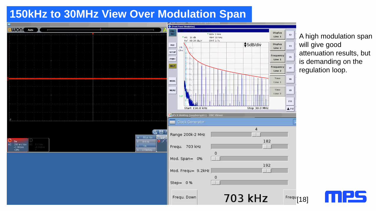
150kHz to 30MHz View Over Modulation Span
A high modulation span
will give good
attenuation results, but
is demanding on the
regulation loop.
[18]
5dB/div
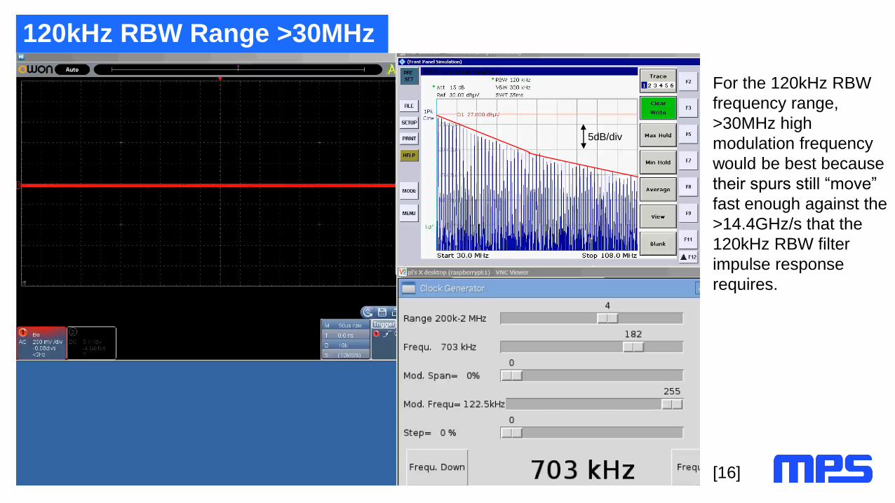
120kHz RBW Range >30MHz
For the 120kHz RBW
frequency range,
>30MHz high
modulation frequency
would be best because
their spurs still “move”
fast enough against the
>14.4GHz/s that the
120kHz RBW filter
impulse response
requires.
[16]
5dB/div
Modulation Waveforms
[16]
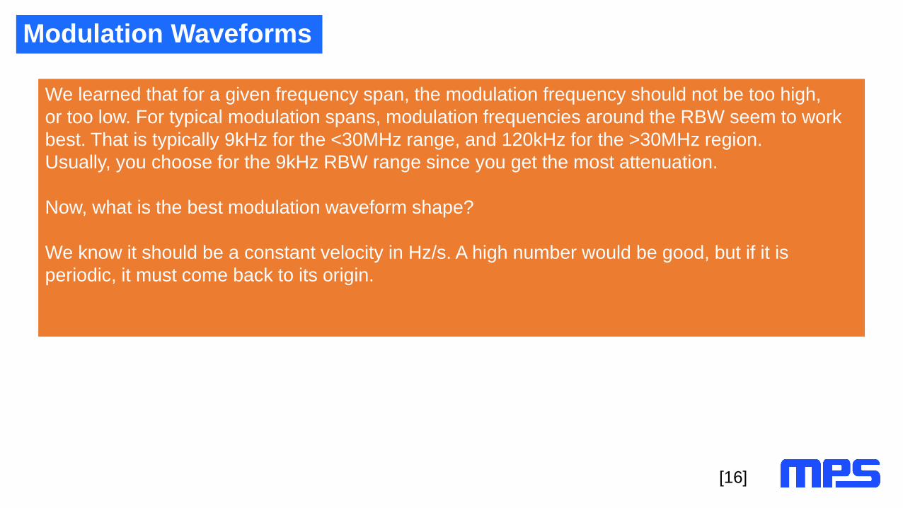
We learned that for a given frequency span, the modulation frequency should not be too high,
or too low. For typical modulation spans, modulation frequencies around the RBW seem to work
best. That is typically 9kHz for the <30MHz range, and 120kHz for the >30MHz region.
Usually, you choose for the 9kHz RBW range since you get the most attenuation.
Now, what is the best modulation waveform shape?
We know it should be a constant velocity in Hz/s. A high number would be good, but if it is
periodic, it must come back to its origin.

Modulation Waveforms – Triangular
[16]
t1 t1
Δf
Δf/2
The problem here is that in
the same time (t1) makes
only half of the frequency
change.
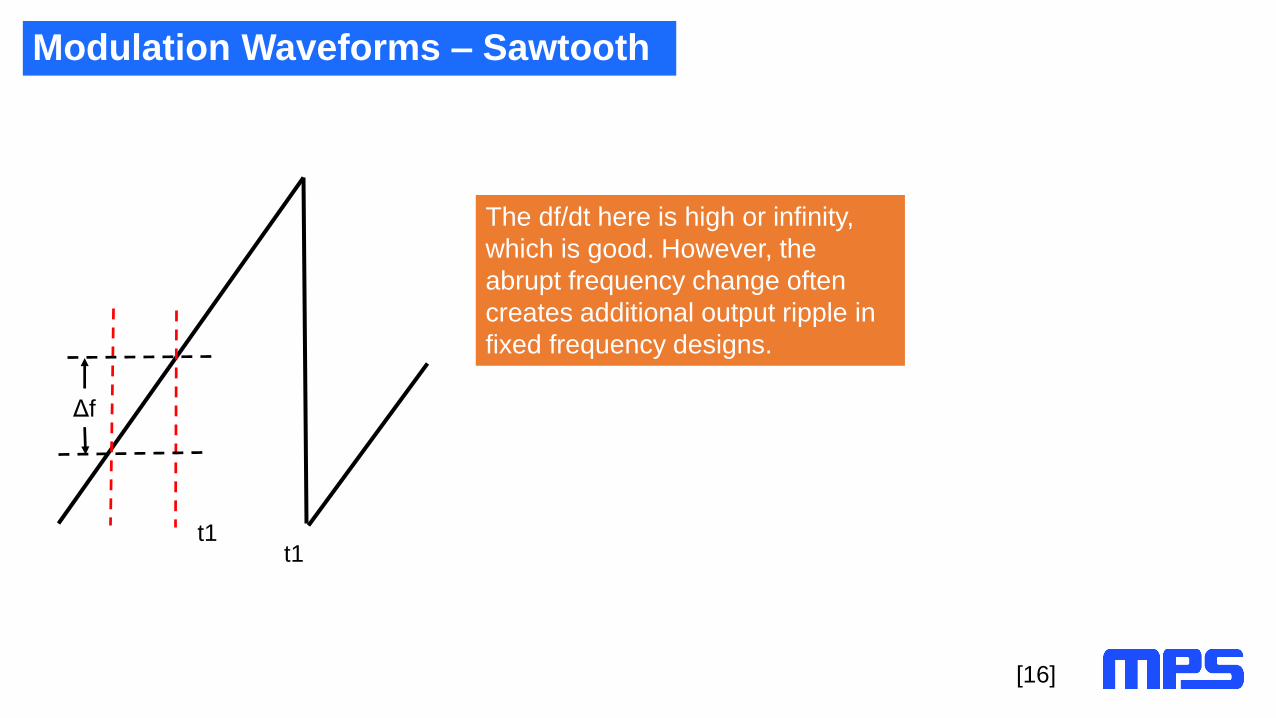
Modulation Waveforms – Sawtooth
[16]
t1t1
Δf
The df/dt here is high or infinity,
which is good. However, the
abrupt frequency change often
creates additional output ripple in
fixed frequency designs.

Modulation Waveforms – “Hershey kiss” and Stepped Triangular
[16]
t1 t1
Δf
Δf
t1 t1
Δf
Δf
=Constant df/dt

Pseudo-Random Noise for Spread Spectrum Modulation
Industry-available, pseudo-random spread
spectrum generator.
No attenuation in PK nor in AV mode at 9kHz RBW.
[19]
5dB/div
Fixed frequency carrier

Pseudo-Random 150kHz to 30MHz
Industry-available, pseudo-random spread
spectrum generator. A few dB.
[20]
5dB/div
9kHz Triangle Modulation @ 20% Span

Spread Spectrum Implementation for Parts without Internal FSS
If they have a resistor program FREQ pin
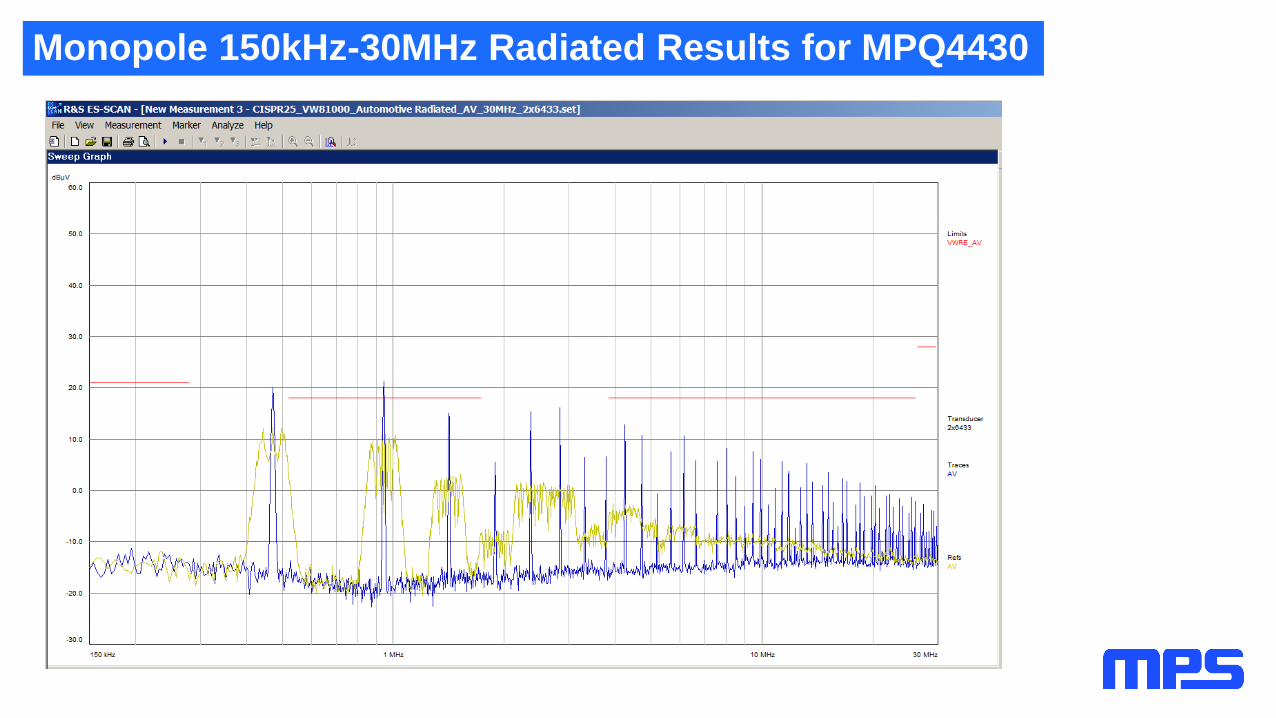
Monopole 150kHz-30MHz Radiated Results for MPQ4430

Digital Implementation in the MPQ8875
Spread Spectrum Benefits
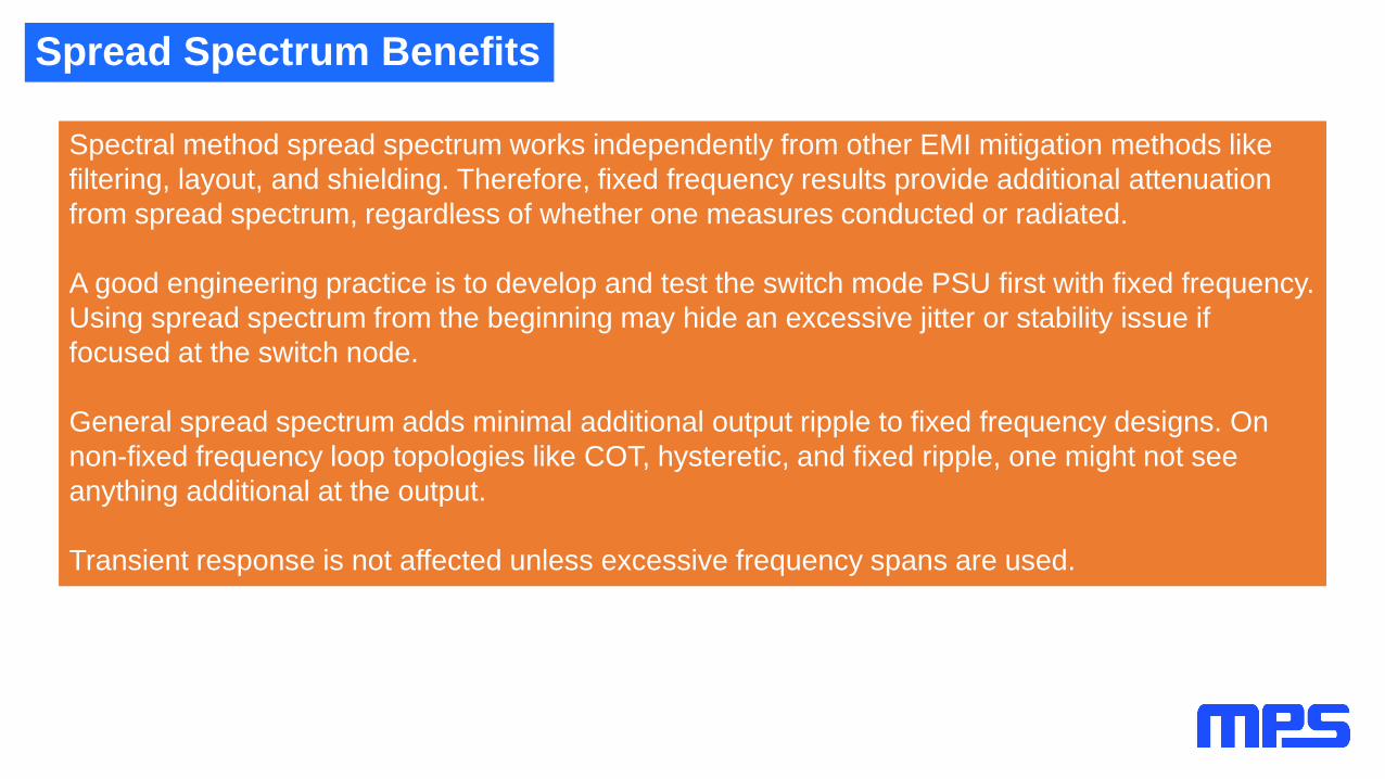
Spectral method spread spectrum works independently from other EMI mitigation methods like
filtering, layout, and shielding. Therefore, fixed frequency results provide additional attenuation
from spread spectrum, regardless of whether one measures conducted or radiated.
A good engineering practice is to develop and test the switch mode PSU first with fixed frequency.
Using spread spectrum from the beginning may hide an excessive jitter or stability issue if
focused at the switch node.
General spread spectrum adds minimal additional output ripple to fixed frequency designs. On
non-fixed frequency loop topologies like COT, hysteretic, and fixed ripple, one might not see
anything additional at the output.
Transient response is not affected unless excessive frequency spans are used.
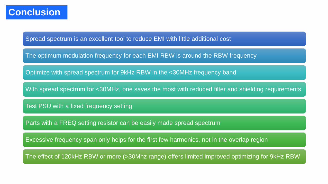
Spread spectrum is an excellent tool to reduce EMI with little additional cost
The optimum modulation frequency for each EMI RBW is around the RBW frequency
Optimize with spread spectrum for 9kHz RBW in the <30MHz frequency band
With spread spectrum for <30MHz, one saves the most with reduced filter and shielding requirements
Test PSU with a fixed frequency setting
Parts with a FREQ setting resistor can be easily made spread spectrum
Excessive frequency span only helps for the first few harmonics, not in the overlap region
The effect of 120kHz RBW or more (>30Mhz range) offers limited improved optimizing for 9kHz RBW
Conclusion
FAQ: Question 1
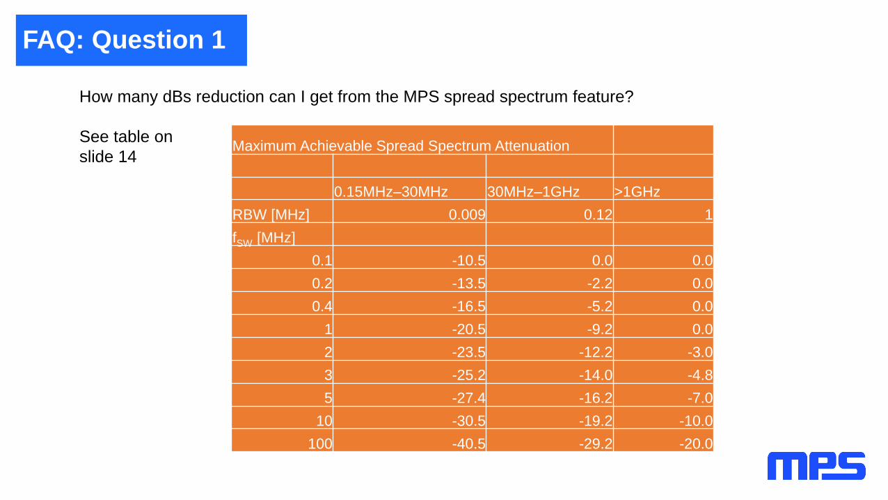
How many dBs reduction can I get from the MPS spread spectrum feature?
See table on
slide 14 Maximum Achievable Spread Spectrum Attenuation
0.15MHz–30MHz 30MHz–1GHz >1GHz
RBW [MHz] 0.009 0.12 1
fSW [MHz]
0.1 -10.5 0.0 0.0
0.2 -13.5 -2.2 0.0
0.4 -16.5 -5.2 0.0
1 -20.5 -9.2 0.0
2 -23.5 -12.2 -3.0
3 -25.2 -14.0 -4.8
5 -27.4 -16.2 -7.0
10 -30.5 -19.2 -10.0
100 -40.5 -29.2 -20.0
FAQ: Question 2
Q: Does spread spectrum affect the transient response of a DC/DC buck regulator?
A: It has almost no effect since the mean switching frequency stays the same.
FAQ: Question 3
Q: Which algorithm is used to generate spread spectrum inside MPS’s DC/DC converters?
A: Analog triangle or stepped triangle generators are used as well as digital implementations.
As long as the digital implementation changes the frequency value on each switch node cycle,
there is no difference in the resulting spectrum and attenuation.
FAQ: Question 4
Q: Which frequency modulation envelope is more effective: sawtooth, triangle, or sinusoid?
A: Sawtooth and stepped triangle are the most effective. However, sawtooth makes a jump over the
complete range in one step, which can introduce loop perturbation for the switcher. Because of this, a more
continuous method like triangle or stepped triangle are often used.
Sinusoid or even rectangular modulation stay at the top and bottom signal too long around a small
frequency range (inside the RBW), which results in poor attenuation.
FAQ: Question 5
Q: What is the cost difference, if any, to be expected in a SS part vs. non-SS part? Will there be an overall
reduction is system cost (capacitors, inductor, filters)?
A: The additional audio frequency modulator adds very little area on the device, so the additional cost is low.
The biggest solution cost improvement is on the filter requirements for the lower frequency area from
switching frequency to the first harmonics.
Often, spread spectrums save the complete solution, so ultimately only you can answer what your project is
worth.
FAQ: Question 6
Q: Does spread spectrum really help the EMI? Or just cheat the test equipment?
A: The total emitted energy into the universe stays the same. You change the spectral distribution.
FAQ: Question 7
Q: Which kind of EMI does it help? CE? RE? <30MHz? >30MHz?
A: All are the same. Spread spectrum is a spectral method, and always gives additional dB attenuation to
conventional methods like filtering, layout, and shielding.
Therefore, it helps the same for both conducted and radiated, and gives the same dB attenuation at any
frequency, whether radiated and conducted.
With the different RBW (resolution bandwidth) of 9kHz <30MHz, 120kHz >30MHz, and 1MHz >1GHz, in
some OEM defined ranges spread spectrum attenuates the most for low RBW like 9kHz.
See slide 16 for carrier frequency change minimums.
150kHz to 30MHz with RBW = 9kHz > 81MHz/s
30MHz to 1GHz with RBW = 120KHz > 14.4GHz/s
>1GHz with RBW = 1MHz > 1THz/s
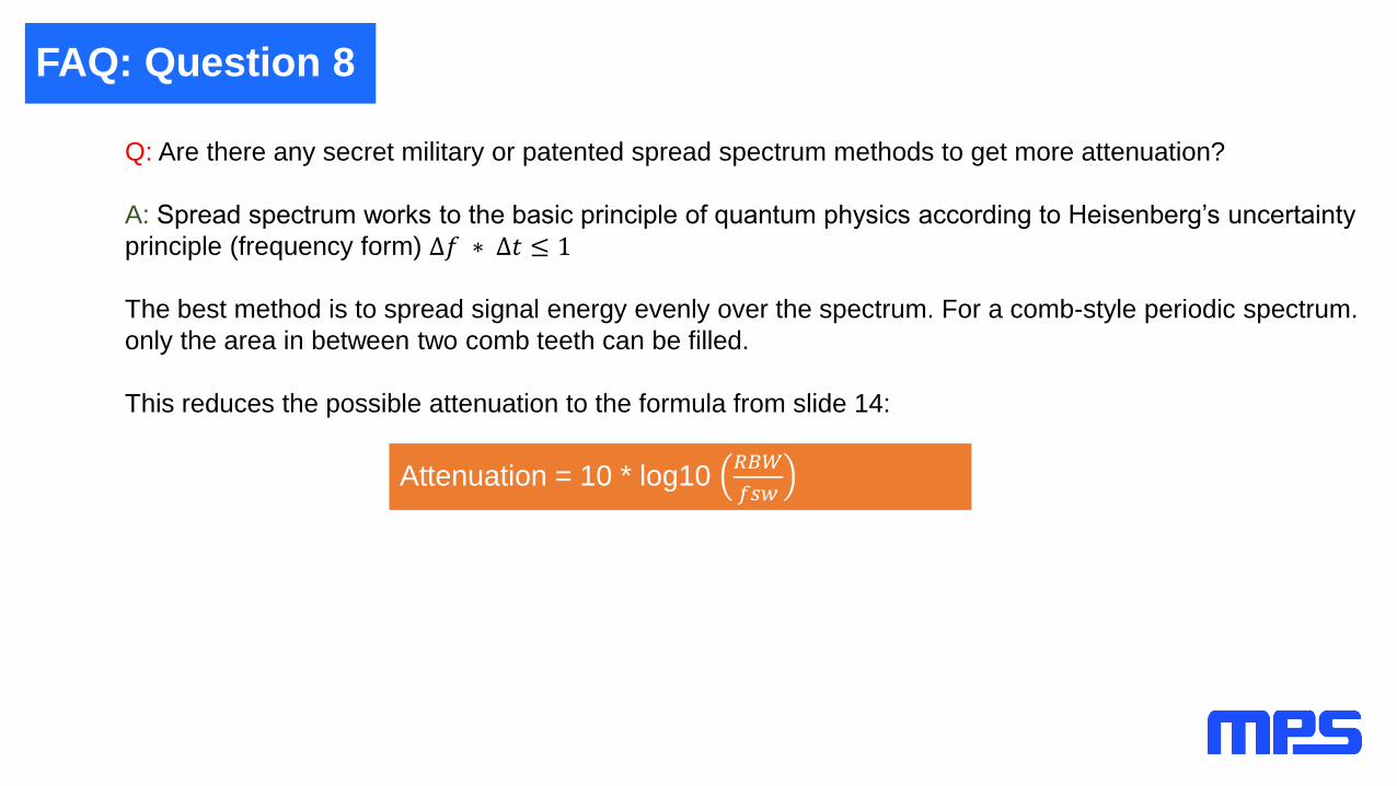
FAQ: Question 8
Q: Are there any secret military or patented spread spectrum methods to get more attenuation?
A: Spread spectrum works to the basic principle of quantum physics according to Heisenberg’s uncertainty
principle (frequency form) ∆𝑓 ∗ ∆𝑡 ≤ 1
The best method is to spread signal energy evenly over the spectrum. For a comb-style periodic spectrum.
only the area in between two comb teeth can be filled.
This reduces the possible attenuation to the formula from slide 14:
Attenuation = 10 * log10 𝑅𝐵𝑊
𝑓𝑠𝑤

FAQ: Question 9
Q: Why is random or pseudo-random modulation a bad choice?
A: PSU spread spectrum has to use a constant power modulation scheme, which is FM. FM gives a
quadradic spectral energy between ±Carson frequency. Therefore, low modulation frequencies make more
spectral energy then high ones for the same frequency span.
That is the reason that audio FM modulation uses pre-emphasis (50µs in Europe 75µs in US). Otherwise,
the signal to noise ratio for high frequencies would be much lower than for low frequencies. Low carrier
movement staying inside the RBW does not give any attenuation at all.
White noise/random or pseudo-random yields a flat frequency response. One would have to differentiate the
noise signal (high frequencies amplified), pre-emphasize it, and cut out the low amplitude area, which would
result in the carrier staying inside the RBW. The high frequency range requires limiting the energy giving a
low modulation index. In total, one would have to bandpass, pre-emphasize, and omit low-amplitude
changes (inside RBW). In the end, the signal would not be much different from a stepped triangle.
Currently, white noise/pseudo-random generators give lower attenuation than otherwise possible for the
above reasons.
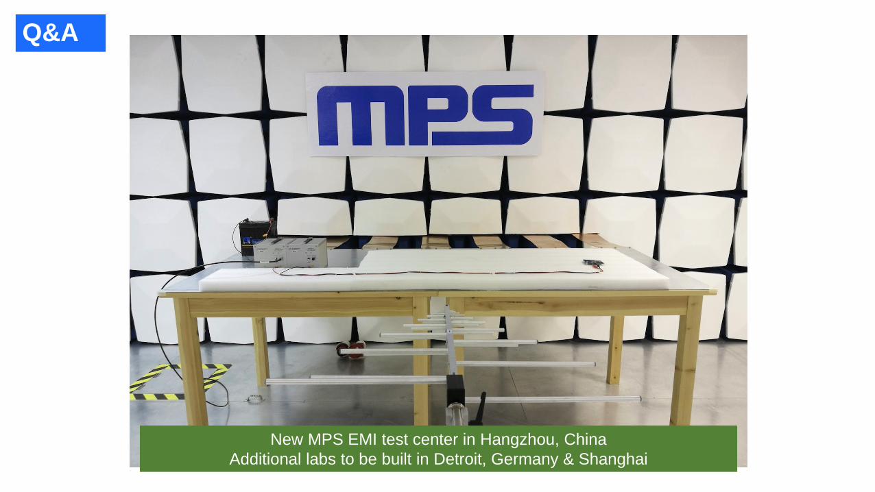
Q&A
New MPS EMI test center in Hangzhou, China
Additional labs to be built in Detroit, Germany & Shanghai
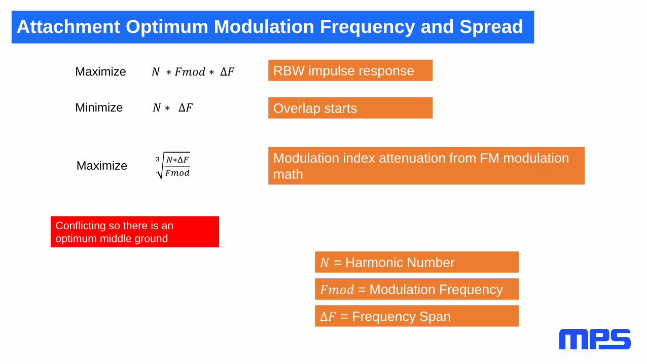
Attachment Optimum Modulation Frequency and Spread
signal frequency and with magnitudes according to the Bessel function of the first kind
RBW impulse responseMaximize 𝑁 ∗ 𝐹𝑚𝑜𝑑 ∗ Δ𝐹
Minimize 𝑁 ∗ Δ𝐹
Maximize 3 𝑁∗Δ𝐹
𝐹𝑚𝑜𝑑
Overlap starts
Modulation index attenuation from FM modulation
math
𝑁 = Harmonic Number
𝐹𝑚𝑜𝑑 = Modulation Frequency
Δ𝐹 = Frequency Span
Conflicting so there is an
optimum middle ground
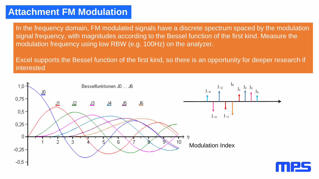
Attachment FM Modulation
J0J1
J2 J3J4J−4
J−3
J−2
J−1
modulation signal frequency, with magnitudes according to the Bessel function of the first kind.
In the frequency domain, FM modulated signals have a discrete spectrum spaced by the modulation
signal frequency, with magnitudes according to the Bessel function of the first kind. Measure the
modulation frequency using low RBW (e.g. 100Hz) on the analyzer.
Excel supports the Bessel function of the first kind, so there is an opportunity for deeper research if
interested
Modulation Index

Attachment Overlap
The spread frequency span goes up with the harmonic number N, and
starts to overlap at a certain frequency.
Above the overlap frequency, EMI will not improve by increasing the
modulation frequency span/spread.
𝑓0 𝑓1 𝑓2 𝑓3 𝑓4 …..0

Attachment Switching Frequency Effect on EMI
Doubling the switching frequency doubles the number of switch transitions, so it is best to double
the EMI energy. That is 3dB more (power is 10 * log(2)).
But with double the frequency, only half the bins are available to locate this energy.
The spurs have 6dB more amplitude per doubling the frequency for fixed frequency, and at least
3dB more for a perfect working spread spectrum.
f
0dB
6dB

Attachment Switching Frequency Effect on EMI
EMI energy is
proportional to the
switching frequency
3db/octave =
10db/decade
With fixed frequency for
every doubling, only half
the bins are available for
the energy.
Result is 6dB/octave =
20db/decade
2xx x x
Increase in Switching Frequency
If all stays the same except the switching frequency:
4x
EM
I In
cre
ase
in
dB
Fixed Frequency
Perfect Spread Spectrum