spread spect principles - TKK Tietoliikennelaboratorio€¦ · 3 1. BASIC PRINCIPLES OF SPREAD...
23
S-72.333 Post-graduate Course in Radio Communications 2001-2002 Spread Spectrum Principles and Methods Jarmo Oksa Email: [email protected] Date: 12.2.2002
Transcript of spread spect principles - TKK Tietoliikennelaboratorio€¦ · 3 1. BASIC PRINCIPLES OF SPREAD...
S-72.333Post-graduate Course in Radio Communications
2001-2002
Spread Spectrum Principles and Methods
Jarmo OksaEmail: [email protected]
Date: 12.2.2002
2
1. BASIC PRINCIPLES OF SPREAD SPECTRUM...........................................................................3
1.1 DIRECT SEQUENCE (DS) SPREAD SPECTRUM...................................................................................71.1.1 Complex spreading.................................................................................................................71.1.2 Dual channel quaternary spreading.........................................................................................81.1.3 Balanced quaternary spreading...............................................................................................81.1.4 Simple binary spreading .........................................................................................................9
1.2 FREQUENCY HOP (FH) SPREAD SPECTRUM .................................................................................10
2. SPREADING SEQUENCES ............................................................................................................12
2.1 SPREADING WAVEFORMS .............................................................................................................152.2 M-SEQUENCES .............................................................................................................................152.3 GOLD SEQUENCES.........................................................................................................................182.4 KASAMI SEQUENCES ....................................................................................................................192.5 BARKER SEQUENCES....................................................................................................................202.6 WALSH-HADAMARD SEQUENCES.................................................................................................20
3. POWER SPECTRAL DENSITY OF SPREAD SPECTRUM SIGNALS....................................21
REFERENCES......................................................................................................................................23

3
1. BASIC PRINCIPLES OF SPREAD SPECTRUM
Since 1940's spread spectrum systems were developed for antijam and low probability ofintercept (LPI) applications [10] by spreading the signal over a large frequency band andtransmitting it with a low power per unit bandwidth. In the antijam systems spectralspreading secures the signal against narrowband interferers (Figure 1, [4]) and in the LPIsystems it to makes the detection as difficult as possible for an unwanted interceptor byhiding the signal in the noise.
Figure 1 : Narrowband interference rejection ([4] : Figure 5.17)
In the spread spectrum systems instead of allocating disjoint frequency channels or timeslots for different users the simultaneous users are on the same frequency band. Thefundamental problem of spread spectrum in a multiple access communication application(code division multiple access, CDMA) is that each user causes multiple accessinterference (MAI) affecting all the other users. When the spectral efficiency of thedifferent multiple access methods was calculated by taking into account the originalsignal bandwidth, the guard bands for FDMA, guard time for TDMA and MAI forCDMA but not the channel properties the following results were obtained : (Table 1) [4].

4
Table 1 : Summary of multiple access technologies ([4] Dixon, Spread Systems withCommercial Applications : Table 12.2 )
Lower level of spectral efficiency was obtained for CDMA. In the early multiple accesssystems CDMA did not give clear advantage over TDMA/FDMA. The narrowbandmethods FDMA and TDMA are more sensitive to channel impairments but unless theyare serious enough MAI is the dominating source of errors. Error probability calculationsbased on MAI modeled as AWGN can be found in [2] and [3].
However, recently spread spectrum technology has become a viable alternative forcellular systems. The advantages of using spread spectrum for cellular applicationsinclude: inherent multipath diversity (large bandwidth allows using many multipathcomponents in the RAKE receiver), soft capacity (by exploiting the capacity withoutreallocating channels), soft hand off capability, improved spectral efficiency (no need forthe frequency reuse distance between cells and guard bands of adjacent frequencies)narrow band interference rejection (Figure 1, [4]) and inherent message privacy.[1] Themain disadvantage of spread spectrum is caused by MAI: the detected signals must becontrolled to have equal power to avoid the near-far effect.
In a spread spectrum system the data symbols x = {xn} are modulated onto a carrier byusing a spreading sequence (signature sequence, spreading code) a = {ak} that is differentfor each user. This sequence spreads the transmitted signal bandwidth to be much largerthan the data signal bandwidth. The spread spectrum system contains the followingoperations : data modulation of bits to symbols, spreading (bandwidth expansion) andcarrier modulation [5] :

5
Transmitter :
Receiver :
Spreading can be performed either on the baseband or on the carrier frequency:
DatasymbolsequencexnData
modulationSpreading
Spreadingsequence an
Figure 2
Despreading Datademodulation
Datasymbolsequencexn
Databits
DatabitsRe{a(t)⋅x(t)⋅ej2πft}
Possible places for carrier modulation and demodulation
Spreadingsequence an
Passband signal :
Because in general the data and spreading sequences are complex the transmitted signalcan be modeled as the real part of the product of three complex signals :
{ }tfj cetxtats π2)()(Re)( ⋅⋅=
,where the part a(t)⋅x(t) that is used to modulate the carrier is called the complex envelopeThe complexity is implemented by the phase-shifted I- and Q-carriers. (The signals withreal and imaginary parts are drawn by double lines in Figure 2).
6
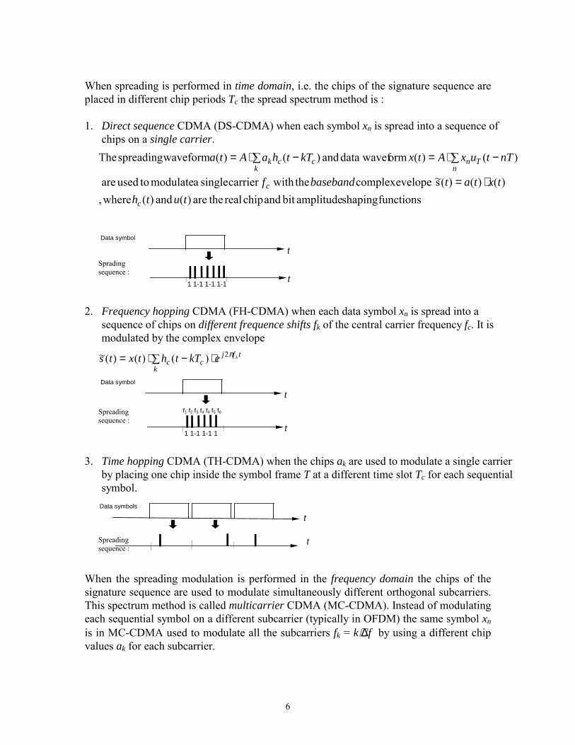
When spreading is performed in time domain, i.e. the chips of the signature sequence areplaced in different chip periods Tc the spread spectrum method is :
1. Direct sequence CDMA (DS-CDMA) when each symbol xn is spread into a sequence ofchips on a single carrier.
functions shaping amplitudebit and chip real theare )( and )( where,)()()(s~ evelopecomplex the withcarrier singlea modulate toused are
)()( ormdata wavef and )()( waveformspreading The
tuthtxtatbasebandf
nTtuxAtxkTthaAta
c
c
nTn
kcck
⋅=
� −⋅=� −⋅=
Data symbol
Spradingsequence :
t
t1 1-1 1-1 1-1
2. Frequency hopping CDMA (FH-CDMA) when each data symbol xn is spread into asequence of chips on different frequence shifts fk of the central carrier frequency fc. It ismodulated by the complex envelope
� ⋅−⋅=k
tfjcc
kekTthtxts π2)()()(~
Data symbol
Spreadingsequence :
t
t1 1-1 1-1 1
f1 f2 f3 f4 f4 f5 f6
3. Time hopping CDMA (TH-CDMA) when the chips ak are used to modulate a single carrierby placing one chip inside the symbol frame T at a different time slot Tc for each sequentialsymbol.
Data symbols
Spreadingsequence :
t
t
When the spreading modulation is performed in the frequency domain the chips of thesignature sequence are used to modulate simultaneously different orthogonal subcarriers.This spectrum method is called multicarrier CDMA (MC-CDMA). Instead of modulatingeach sequential symbol on a different subcarrier (typically in OFDM) the same symbol xnis in MC-CDMA used to modulate all the subcarriers fk = k⋅∆f by using a different chipvalues ak for each subcarrier.

7
However, OFDM can be used together with MC-CDMA by converting a block of serialdata symbols into a block of parallel data symbols and modulating each parallel symbolon a different set orthogonal subcarriers.
Datasequencex1 …xN
SerialParallelConverter
x1 a1ej2π∆ft
Figure 3 [6]
Spreadingmodulatorx1
X2
xN
x1 aKej2πK∆ft
1.1 DIRECT SEQUENCE (DS) SPREAD SPECTRUM
In a DS spread spectrum system (Data modulated carrier is modulated directly by a codesequence) the ratio of the symbol and chip periods is called the processing gain G = T / TcThe temporal length of one code period of a short code sequence is equal to the symbolperiod (G = N, T =N⋅Tc ). The code period of a long code sequence contains severalsymbol periods (G<<N, T <<N⋅Tc). Short codes are used by multiuser detection systemsbecause they use the bit periodic property of the short codes for MAI canceling.Otherwise the long codes are preferred because the interference from all users becomesidentical on the average. [9]Data symbols
Spreadingsequemce
t
t
Sequence period of a long code
1.1.1 Complex spreading :
When the spreading a(t) and data x(t) sequences are complex QPSK sequences :a(t)=aI(t)+j⋅ aQ(t) (complex sequence) x(t)=xI(t)+j⋅ xQ(t) (complex sequence)a = {ak : ak ∈ {±1,±j}}) , x={xn:xn∈ {±1/√2,±j /√2},
the complex envelope (baseband signal that is used to modulate the I- and Q- carriers) is [1] :
[ ] [ ][ ] QIIQQIQQII
QIQI
sjstxtatxtajtxtatxtatxjtxtajtatxtat
~~)()()()()()()()(
)()( )()()()()(s~
´´
´
⋅+=+⋅+−=
⋅+⋅⋅+=⋅=
This can be implemented with the complex spreading circuit :

8
Figure 4 : Complex spreading ([1] : Figure 9.2)
1.1.2 Dual channel quaternary spreading :
When the spreading sequence a(t) is real the I- and Q-channels have independentspreading sequences aI(t) and aQ(t). The data sequence x(t) can be QPSK modulated orconsist of independent BPSK modulated data sequences xI(t) or xQ(t). When BPSK datamodulation is used x(t) is real and xI(t) and xQ(t)are independent data sequences
a(t)=aI(t) and aQ(t) (real sequence)x(t)= xI(t) +j⋅ xQ(t) or x(t)= xI(t) and xQ(t) (complex or 2 real sequences)aI,Q = {ak : ak ∈ {±1,}} , xI,Q={xn:xn∈ {±1/√2,±j /√2},
This can be implemented by the dual channel quaternary spreading circuit :
Figure 5 : Dual channel quaternary spreading([1] : Figure 9.3)
1.1.3 Balanced quaternary spreading :
When the spreading sequence is real a(t) having independent sequences aI(t) and aQ(t)for the I- and Q-carrier and only one real BPSK data sequence x(t) is used
a(t)=aI(t) and aQ(t) (real sequences)x(t) (one real data sequence)aI,Q = {ak : ak ∈ {±1,}} , x={xn:xn∈ {±1}

9
This can be implemented by the balanced quaternary spreading circuit :
Figure 6 :Balanced quaternaryspreading ([1] : Figure 9.4b)
1.1.4. Simple binary spreading :
One real BPSK modulated data sequence can be also spread to a single carrier by thesimple binary spreading :
a(t) (one real spreading sequence)x(t) (one real data sequence)a = {ak : ak ∈ {±1,}} , x={xn:xn∈ {±1}:
Figure 7 : Simple binary spreading([1] : Figure 9.4a)
The DS spread spectrum receiver performs the following functions: code synchronizationwith the incoming sequence, phase synchronization with the incoming phase in the caseof coherent detection, despreading and filtering the signal and detecting the data. Codeand phase synchronization consist of acquisition and tracking operations.
The received signal can be despread by using a matched filter or correlator. Matchedfilters are used with incoherent detection and for code acquisition with the coherentdetection.

10
Figure 8 : Simplified DS/QPSK system ([1] : Figure 9.1)
The bit error probability of DS/QPSK with Gray coding given by a ML receiver in anAWGN channel is identical to QPSK [1]:
( )0/2 NEQP be ⋅= , which is identical to conventional coherent QPSK.
Spreading and despreading do not improve Pe in an AWGN-channel because bandwidthexpansion is independent of data and spreading does not affect the spectral andprobability density functions of AWG-noise [1] ,[7].
DS spread spectrum system with pseudonoise sequencies is an averaging type system.Multiple access interference from other users is reduced by averaging it.
1.2 FREQUENCY HOP (FH) SPREAD SPECTRUM
In frequency hopping spread spectrum systems the carrier frequency hops throughout afinite set of frequencies during the code period. FH spread spectrum system is anavoidance type system in which interference is reduced by avoiding same frequencies.
There are two basic types of FH spread spectrum: slow frequency hopping (SFH) and fastfrequency hopping (FFH). SFH systems transmit one or more data symbols per hop. FFHsystems transmit the same data symbol on multiple sequential hop frequencies.
11
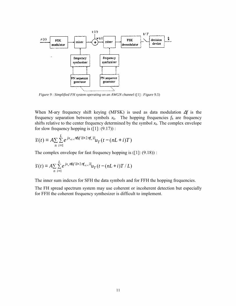
Figure 9 : Simplified FH system operating on an AWGN channel ([1] : Figure 9.5)
When M-ary frequency shift keying (MFSK) is used as data modulation ∆f is thefrequency separation between symbols xk. The hopping frequencies fh are frequencyshifts relative to the center frequency determined by the symbol xk. The complex envelopefor slow frequency hopping is ([1]: (9.17)) :
� � +−==
⋅+⋅∆+
n
L
iT
tftfjx TinLtueAts ninL
1
2 ))(()(~ ππ
The complex envelope for fast frequency hopping is ([1]: (9.18)) :
� � +−==
⋅+⋅∆ +
n
L
iT
tftfjx LTinLtueAts inLn
1
2 )/)(()(~ ππ
The inner sum indexes for SFH the data symbols and for FFH the hopping frequencies.
The FH spread spectrum system may use coherent or incoherent detection but especiallyfor FFH the coherent frequency synthesizer is difficult to implement.

12
2. SPREADING SEQUENCES
The spreading sequences can be classified as orthogonal sequences and pseudonoise (PN)sequences. The cross correlation of the orthogonal sequences is zero and so MAI fromother users is cancelled. Orthogonal sequences are used in synchronous CDMA systemsbecause the cross correlation function varies remarkably as a function of the time shift ofthe sequences.
The pseudonoise (PN) sequences have auto-correlation function that is similar to whiteGaussian noise. The received sequences from other users are also noise-like signals. MAIfrom other users is distributed evenly in time and between the interfering users. Thisallows asynchronous operation. They are chosen to have three desirable attributes [1]:
1) Each element of the sequence (1,0 or +1,-1) occurs with equal frequency,2) The auto-correlation has small off-peak values to allow rapid sequence acquisition and3) Cross-correlation is small at all delays.
However, the attributes 2) and 3) are difficult to achieve simultaneously. Designing thesequences to have low cross correlation reduces the randomness of the sequences andincreases the off-peak values of the auto-correlation function. [8]
Spreading sequences are often characterized in terms of their discrete-time correlationproperties with the time shift n. When short codes are used the auto- and cross-correlationare calculated over a full sequence period N. When they are calculated periodically thevalues of sequential data symbols are ignored.
The periodic auto-correlation of the k-th complex spreading sequence a(k) over a a fullperiod N is ([1])
�=−
=+
1
0
)()(,
*
21)(
N
i
kni
kikk aa
Nnφ
and the periodic cross-correlation over a full period N between the k-th and m-th sequencesa(k) and a(m) is ([1])
�=−
=+
1
0
)()(,
*
21)(
N
i
mni
kimk aa
Nnφ
The aperiodic auto-correlation over the full period N of the sequence a(k) calculates onlythe overlapping part of the sequences ([1]).

13
���
�
���
�
�
≥
≤≤+−�
� −≤≤
=+
=−
−
=+
Nn
nNaaN
NnaaN
nnN
i
kni
ki
nN
i
ki
kni
kka
, 0
01 , 21
10 , 21
)(1
)()(1
)()(
,*
*
φ
Similar equations are obtained for the aperiodic cross-correlation of sequences a(k) anda(m) over a full period N.
tkT (k+1)T
ak:
am :
Periodic cross-correlation over fullperiod :
t
Aperiodic cross-correlationover full period:
kT (k+1)T
Figure 10 : Periodic and aperiodic full period auto- and cross-correlations
ak:
am :
N=T
n>0
[ ]2 )()()( ,,, Nnnn kka
kka
kk −+= φφφ
By using the aperiodic auto-correlation the effect of different consequent symbols can betaken into account [2]:
1,-1)( symbols consequent are and , )()(),,( 01,1,001, +−⋅+⋅= −−− bbNnbnbbbn kka
kka
kk φφφ
When long codes are used the partial period auto- and cross-correlations are calculatedover the bit period T=G⋅Tc instead of the whole sequence period N ([1]).
�=−
=+
1
0
)()(,
*
21)(
G
i
kni
kikk
p aaG
nφ
�=−
=+
1
0
)()(,
*
21)(
G
i
mni
kimk
p aaG
nφ

14
tkT (k+1)T
ak:
am :
Periodic correlation overpartial period:
t
Aperiodic correlation overpartial period:
Figure 11 : Periodic and aperiodic partial period auto- and cross-correlations
ak:
am :
Symbol period
Sequence period
The partial period correlations are not only a function of the delay n, but also dependupon the point in the sequence where the summation actually starts. They are difficult toderive analytically. Therefore, statistical auto- and cross-correlations are used assumingthat the sequences with elements {±1,±j} are randomly generated.
The mean and variance of the partial period autocorrelation (periodic) are ([1])
[ ] [ ]���
≠=
==�==−
=+ Nn
NnaaE
GnEn Nn
G
i
mni
kikk
pkk
p
�
�
� , 0 . 1
21)()( ,
1
0
)()(,
*
,δφµφ
( )���
≠=
=−=−���
��=
NnGNn
GnnEn Nnkk
pkk
pkk
p
�
�
� , /1 . 011)()()( ,
22,
2,, δµφσ φφ
The mean and variance of the partial period cross-correlation (periodic) are ([1])
[ ] nnEn mkp
mp ∀== , 0)()( ,φµφ
nGnnEn mkp
mkp mk
p ∀=−���
���= , /1)()()( ,,
22,
2φφ µφσ

15
2.1 SPREADING WAVEFORMS
In asynchronous systems the auto- and cross-correlation for the continuous-time waveformsdepend also on the amount of overlapping δ of the chip waveforms :
δ
hc(t)
Figure 12 : Chip overlapping
ck
ck
l
t'
t'
Tc0
The continuous-time periodic cross-correlation over a full period between the spreadingwaveforms a(k)(t) and a(m)(t) depends both on the time shift between the sequences l(earlier n) and the chip overlapping time shift δ ([1]) :
nscorrelatio waveformchip : )(ˆ, )(, )(ˆ)1()()(
, )()(1)(
,,
0
)()(,
δδδφδφ
δτττ
hhhmkhmk
c
Tmk
mk
RRRR
TdttataT
R
++=
+=� +=
��
�
For rectangular chip waveform hc(t) = uTc(t) :
δτδφδφτ +=++���
����
� −= cc
mkc
mkmk TTT
R ��� , )1(1)()( ,,,
The maximum auto- and cross-correlations are obtained by the chip-synchronousapproximation (δ=0) :
)()( , )()( ,,,, �� mkmkkkkk RR φτφτ ≤≤
The partial period auto- and cross correlations are statistical funtions.
2.2 M-SEQUENCES
A widely used type of PN sequences are the maximum-length shift-register sequences(LFSR), m-sequences. Each sequence is generated by a separate LFSR that has m stages.The period of the sequence (sequence length) is N = 2m –1. They are the longestsequences that can be generated by an LFSR for a given m. [1]

16
Figure 13 : m-sequence generator ([1] : Figure 9.6)
The multipliers pi ∈ {0,1} and ⊕ denotes modulo 2 addition . The elements (chips) ofthe sequence ai ∈ {0,1} are mapped to {+1,-1} for bipolar coding. The sequence a(k) has2m-1 ones and 2m-1 –1 zeros.
The feedback polynomial is a primitive polynomial of degree m over GF(2) [1] :
P(x) = 1 ⊕ p1x ⊕ p2x2 ⊕ p3x3 ⊕ … ⊕ pm-1xm-1 ⊕ xm
An m-sequence has almost an ideal full period autocorrelation :
���
≠−=
=NnNNn
n�
�
, /1, 1
)(φ
The full period auto-correlation function for continuous time sequence waveforms a(k)(t)when the rectangular chip shaping function hc(t) = uTc(t) is used is :
δτδφδφτ +=++���
����
�−= c
ckk
ckkkk T
TTR ��� , )1(1)()( ,,,
Figure 14 : Typical full period autocorrelation function ofan m-sequence spreading waveform ([1] : Figure 9.7)

17
However, only for certain values of m there exist some pairs of m-sequences with low fullperiod cross-correlation. When the average full period cross-correlation betweensequences a(k) and a(m) is calculated for different shifts n of the sequences:
( ) 1 1
0, n
NN
nmk�=
−
=φθ
the value of θ varies much depending on the particular pair of m-sequences that areselected and the worst θ-values are great.
Tabel 2 : Best and worst case average cross-correlations for m-sequences([1]: Table 9.1)
Figure 15 : Cross-correlation function of typical m-sequences ([4])

18
2.3 GOLD SEQUENCES
A set Gold sequences consist of 2m+1 sequences having the period N = 2m –1 that aregenerated by a preferred pair of m-sequences. This set contains both the preferred pair(a(1),a(2)) and the 2m-1 new generated sequences. The sequences are generated by taking amodulo-2 sum of a(1) with the 2m-1 cyclically shifted versions of a(2) or vice versa.
Figure 16 : A Gold sequence generator with p1(x)= 1+x2+x5 and p2 (x)= 1+x+x2+x4+x5
This sequence generator can produce 32 Gold sequences of length 31. ([1]: Figure 9.8)
Because the Gold sequences are not maximal length sequences (except a(1) and a(2)) theauto-correlation function is not 2-valued. Both the cross-correlation and off-peak auto-correlation functions are 3-valued : {-1, -t(m), t(m)-2}, where
���
+= +
++
even is when, 12odd is when, 2)( 2/)2(
12/)1(
mmmt m
m
So both the cross correlation and off-peak auto-correlation functions are upper boundedby t(m) :

19
Table 3 : Peak cross correlation of m-sequences and Gold-sequences([1] : Table 9.2)
2.4 KASAMI SEQUENCES
The small set of Kasami sequences consists 2m/2 sequences having the period N = 2m –1.This set is generated in a way similar to the Gold sequences by using a pair of a longsequence a(1) and a short sequence a(2) that are m-sequences. This set contains both thelong sequence a(1) and the 2m/2-1 new generated sequences. The sequences are generatedby taking a modulo-2 sum of a(1) with all the 2m/2-1 cyclic shifts of a(2).
Figure 17 : A Kasami sequence generator with p1(x)= 1+x+x6 andp2 (x)= 1+x+x3. This sequence generator can produce 8 Kasamisequences of length 63. ([1]: Figure 9.9)

20
Like for Gold sequences the cross-correlation and off-peak auto-correlation functions are3-valued. The possible values are : {-1, -s (m), s(m)-2}, where
12)( 2/ += mmtThe upper bound s(m) for the cross correlation and off-peak auto-correlation functions isreduced to half compared with the Gold sequences of the same length.
The large set of Kasami sequences contains also Gold sequences and hence the cross-correlation and off-peak autocorrelation values are on the average higher than in the smallset of Kasami sequences.
2.5 BARKER SEQUENCESThe Barker sequences are aperiodic sequences (finite length sequences). Their cross-correlation and off-peak auto-correlation values are limited by 1/N but they are knownonly for code lengths N=2,3,4,5,7,11. Because the Barker sequences are short and theirnumber is limited they are used for special purpose systems (as for initial synchronizationand wireless LANs).
��
���
≠−
== 0n, 1or
N1 0,
0n, 1)(,
Nnkk
aφ
2.6 WALSH-HADAMARD SEQUENCES
The Walsh-Hadamard sequences are orthogonal sequences. They are the rows of theHadamard matrix that is obtained by the recursion :
��
���
�
−=
MM
MMM HH
HHH2 starting from �
�
���
�
−=
1111
2H
The Walsh-Hadamard sequences can be used either to spread orthogonally (orthogonalCDMA) the signals of the different users or for M-ary orthogonal coding the differentsymbols.
If orthogonal sequences are used for different users accurate synchronization is neededbecause the orthogonal sequences have for non-zero time shifts large cross-correlationand off-peak auto-correlation values.
If orthogonal symbols are used k=log2M bits are used to encode one of the orthogonalsymbols. The user signals are spread by different pseudonoise sequences.

21
3. POWER SPECTRAL DENSITY OF DS SPREAD SPECTRUMSIGNALS
For uncorrelated zero-mean data symbols the power spectral density of the basebandcomplex envelope is ([1] : 4.206)
[ ]( )58.9 :1 )()( 222
~~ fHTAfS axss σ=
,where ha(t) is the amplitude shaping waveform determined by the spreading sequence akand the chip pulse waveform hc(t)
[ ]( )59.9 :1 )()(1
0� −=−
=
N
kccka kTthath
( ) ( ) [ ]( )62.9 :1 )(2 ,22 fNfHfH kkca Φ⋅⋅=
,where Φk,k(f) is the discrete Fourier transform of the aperiodic autocorrelation functionφk,k(n) of the spreading sequence ak.
The power spectral density depends on the spectral product of the chip pulse waveformhc(t) and spreading sequence ak :
[ ]( )64.9 :1 )Φ )()( ,22
2~~ (ffH
TAfS kkcx
css ⋅= σ
For example for the rectangular chip pulse waveform hc(t) and ideal aperiodic auto-correlation function:
���
≠=
=0, 00, 1
)(,nn
nkkaφ
)sinc)( 22~~ ccss (fTTAfS ⋅=
The effect of the deviation from the ideal aperiodic auto-correlation function is calculatedfor the length-11 Barker sequence :
a(1) = (-1 +1 –1 –1 +1 –1 –1 –1 –1 +1 +1 +1) and
for the length-15 m-sequence :
a(2) = (+1 -1 –1 +1 -1 –1 –1 + 1 + 1 +1 +1 –1 +1 –1 +1)
Because the 11-Barker sequence has the aperiodic auto-correlation function that is closerto the ideal one it has smoother power spectral density. For this reason the length-11Barker sequence has been chosen for the IEEE 802.11 wireless LAN specification.

22
Figure 18 ([1]: Figure 9.11) Aperiodicautocorrelation function for the length-11Barker sequence
Figure 19 ([1]: Figure 9.12) Aperiodicautocorrelation function for the length-15m-sequence
Figure 20 ([1]: Figure 9.13) PSD with thelength-11 Barker sequence
Figure 21 ([1]: Figure 9.14) PSD with thelength-11 Barker sequence

23
REFERENCES
[1] Gordon L. Stuber : Principles of mobile communication, 2nd edition, 2001,
Kluwer Academic Publishers
[2] Michael B. Pursley :Performance Evaluation for Phase-Coded Spread-Spectrum Multiple-Access Communication– Part I : System Analysis. Michael B. Pursley, Philip V. Sarwate:– Part II : Code Sequence AnalysisIEEE Transactions on Communications, Vol.Com-25, No. 8, August 1977
[3] Michael B. Pursley, Philip V. Sarwate, Wayne E. Stark : Error Probability for Direct-Sequence Spread-Spectrum Multiple-Access Communications– Part I: Error Probability for Direct-Sequence Spread-Spectrum Multiple-Access Communications :Upper and Lower Bounds, Evaggelos A. Geraniotis, Michael B. Pursley :– Part II: Approximations, IEEE Transactions on Communications, Vol.Com.-30, No. 5, 11, May 1982
[4] Robert C. Dixon : Spread Spectrum Systems with Commercial Applications, 3nd edition, 1994, John Wiley & Sons
[5] Robert A. Scholtz : The Spread Spectrum Concept, IEEE Transactions on Communications, Vol.Com-25, No. 8, August 1977
[6] Ramjee Prasad : Personal Mobile Communications, 1995, McGraw-Hill Series in Electrical Engineering
[7] Kamilo Feher : Wireless Digital Communications, Prentice Hall ,1995, pp. 285-332
[8] Tero Ojanperä, Ramjee Prasad : Wideband CDMA for Third Generation Mobile Communications Artech House, 1998
[9] Stefan Parkvall : Variability of User Performance in Cellular DS-CDMA – Long versus Short Spreading Sequences IEEE Transactions on Communications, Vol. 48, No. 7, July 2000
[10] Robert A. Scholtz : The Origins of Spread-Spectrum Communications, IEEE Transactions on Communications, Vol.Com.-30, No. 5, May 1982