Spray Stakes PC
12
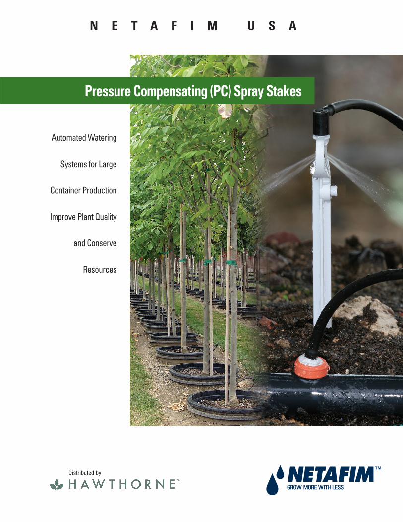
Automated Watering Systems for Large Container Production Improve Plant Quality and Conserve Resources Pressure Compensating (PC) Spray Stakes N E T A F I M U S A Distributed by
Transcript of Spray Stakes PC
Automated Watering
Systems for Large
Container Production
Improve Plant Quality
and Conserve
Resources
Pressure Compensating (PC) Spray Stakes
N E T A F I M U S A
Distributed by

2
110Ten or More Good Reasons to Choose
Netafi m PC Spray Stakes
Superior Wetting of the Soil MixImproves plant quality and conserves resources
2Uniform Watering from the First Pot to the LastImproves plant quality, simplifi es design and controls system costs
Netafi m PC (Pressure Compensating) Spray Stakes were built from the beginning to fi ll the needs of the nursery grower. The spray pattern angles downward - just enough - to keep the spray on the soil and not fl ying into or over the wall of the pot. Water fl ying out of the pot is wasted. Water that hits the side of the pot typically runs down the side and out the bottom of the pot and is not effective in wetting the soil mix.
Water retained by the soil mix is the most important measure of the effectiveness of a spray stake. A poor spray pattern may look good to the eye, but in fact does not apply water uniformly over the soil surface and results in poor water retention. The Netafi m spray pattern provides maximum water retention by the soil mix - exactly what the plant needs. An additional benefi t of the excellent wetting pattern is the uniform activation of top-dressed fertilizers. The result is superior plant growth and more effi cient use of water resources, and fertilizer if liquid feed is being used.
Good Wetting PatternEven distribution means little or no water and fertilizer will be lost from drainage and the roots will grow evenly throughout.
Poor Wetting PatternWhen water is not evenly distributed over the surface of a container, overwatered ‘hot spots’ develop and water channels quickly through the mix and drains away before the plant can use it.
Have you ever measured the difference in the amount of water the plants closest to the valve get compared to those furthest from the valve? It might be much more than you think and it adds up over time.
In a non-pressure compensating design, the spray stakes at the beginning of the line have a higher pressure and supply more water than those at the end of the line. Therefore, plants at the beginning of the line receive more water than they need by the time the plants at the end of the line are suffi ciently watered. Each time the fi eld is watered these differences add up and eventually some plants can outgrow others, resulting in a lack of uniformity and less than a top-quality yield.
Netafi m pressure compensating emitters have been in use for over 20 years and can now be used in spray stake systems. As a result, Netafi m PC Spray Stakes ensure every pot in the entire system receives exactly the same amount of water. This eliminates the need to overwater some plants to be sure the driest plants receive enough water to thrive. This water savings is typically between 5% and 20% and can be even more.

3
10 FeetElevationChange
10 FeetElevationChange
3Have your ever noticed how much mist non-compensating spray stakes produce? It is especially evident on a windy day, as that water is wastefully blown away. One more advantage of pressure compensation is that it conserves water. Even at high pressures, up to 60 psi, the pressure compensating mechanism and the downward water spray of the Netafi m PC Spray Stake eliminate misting.
4Prevents Draindown Onto Lowest PlantsAvoids plant stress from drowning
Everyone knows that water fl ows downhill - just ask the plants at the bottom of a hill. Downhill fl ow is exactly what happens after every irrigation in systems without Netafi m’s check valve feature. All the water in the pipe drains out through the lowest spray stakes downhill. When large pipes are used, this can be a very large volume of water. One hundred feet of 1” pipe contains 15 gallons of water and one hundred feet of 4” pipe contains 65 gallons of water. When tens, or hundreds of gallons of water fl ow out onto the low lying plants after each irrigation, the plants eventually become stressed by excess water.
This problem is eliminated with Netafi m’s built-in check valve feature. The check valve prevents the system from draining(up to 10 feet of elevation) after each irrigation.
Downward Water SprayEliminates misting.
Prevents Water from Blowing Away in the WindSaves water while nearly eliminating misting
Water Drains to the Lowest PlantsWith ordinary spray stakes, at the end of every watering cycle, the pipes drain into the lowest lying plants.
Check Valve Prevents DraindownWith the Netafi m Check Valve feature the pipes stay full and do not drain into the lowest lying plants.

4
6Simplifi es Design LayoutReduces system costs
Pressure compensation has advantages beyond the improvement in watering uniformity.It also simplifi es the design layout and allows you to reduce system costs with:
• Longer runs - see Design Help section for specifi c recommendations
• Smaller supply pipes - pipe downsizing usually pays for the pressure compensation feature
• Fewer sub-mains - a very signifi cant cost, especially in areas of diffi cult trenching
• Fewer valves - longer runs mean a simpler layout requiring fewer system components
7Simple, Secure Shut-OffPrevents water waste and accidental close-offs
The side-mounted, secure shut off is easy and fool-proof. For close-off, remove the nipple and tubing from the top of the spray stake and attach it to the side of the spray stake. This provides a clear, visual indication – even from a distance - if a unit is in the on or off position.
Simple Shut-Off MechanismRemove tubing from top and attach to the side.
WPCJL DripperProvides pressure
compensation.
On Position
Off Position
5Spray Patterns Designed for Nursery ContainersPick the spray pattern that is right for your plants
For simplicity, some growers place the spray stake near the edge of the pot, making the single-sided spray stake the best selection. Other growers prefer the advantages created by our unique ‘bow-tie’ double-spray pattern:
• Doubles the size of the spray pattern, useful for optimized wetting in very coarse mixes, or large pots. One spray stake can do the work of two or more traditional spray stakes.
• Allows positioning of the spray stake near the stem of the plant. This placement minimizes wetting of the base of the stem, a vulnerable point for some plant species.
Plant Trunk
Container
SprayPattern
PC SprayStakeSingle
Spray PatternDouble
Spray Pattern

5
8Adaptable to All Soil Media TypesStake option available
All fl ows are available in a 7” stake.
9Full Range of FlowsChoose the fl ow best suited to your water source and plant needs
Netafi m PC Spray Stakes are color-coded and available in four fl ow options: 3.2 and 6.6 GPH. Color-coded spray stakes make it easy to identify the fl ow from a distance. Based on your water source and plant needs, you can choose the best fl ow for your nursery pots.
10Low MaintenanceLowers cost of operation
Some systems are inexpensive to purchase initially, but as they age the cost of maintenance begins to outweigh the initial low cost. Netafi m PC Spray Stakes are designed to avoid the plugging that occurs in many lower cost stakes. Each individual stake assembly has an inlet fi lter to prevent debris from entering. This fi lter is swept clean by the natural velocity of the water in the pipe. Netafi m recommends appropriate central fi ltration for all spray stake systems but the individual inlet fi lter greatly reduces the incidence of fi eld plugging from construction repair and other contaminants.
11Easy InstallationPrevents problems that increase installation costs
Quick, fool-proof installation lowers costs and prevents problems. There is no risk of mis-cutting or pushing the micro-tubing in too far as some growers experience with standard spray stakes. Simply punch a hole in the supply tube using a Netafi m hole punch, insert the dripper and tubing assembly and attach the spray stake. Each assembly comes ready to use.
Stake Color Flow (GPH)
Plum 3.2 Grey 6.6
Flows
StandardSpray Stake
(shownactual size)
Step 1: Punch a 3mm hole in the supply line tubing.
Step 2: Insert the dripper assembly into the tubing.
Step 3: Attach spray stake to dripper assembly.

6
Selecting the Right Netafi mPC Spray Stake for Your Application
Select the fl ow rate for the spray stake.As long as you have enough water and pressure for the
stake you select, it’s hard to go wrong. Netafi m PC Spray Stakes will work in a very wide range of pot sizes (see table at right for general recommendations). Just remember, these are not strict limitations, just general guidelines. Many growers with larger pots use higher fl ow spray stakes while others prefer to use lower fl ow spray stakes and simply operate them longer.
The next consideration is how long a row or ‘run’ of pots you want to water. Lower fl ow spray stakes can water longer runs than higher fl ow spray stakes. See the Design Help section of this brochure to be sure the fl ow you select will be appropriate for your water resources and fi eld confi guration.
Select the spray pattern.Most fl ow models offer both a single and a double spray pattern. The double spray pattern is selected when
the stake will be placed closer to the trunk of the tree than the side of the container. Here it will wet more soil than the single spray and can be positioned to minimize wetting the base of the trunk.
Container Size Flow (GPH) Stake Color
Product Selection Guide
1 to 5 gallons 3.2 Plum2 to 7 gallons 6.6 Grey
Single SprayPatternBest choice for placing near edge of container.
Double SprayPatternUsed when stake is placed closer to tree trunk.
Second
First

7
Design Help for Netafi m PC Spray Stakes
Determine how many spray stakes you can operate at the same time. Use the Zone Flow chart to establish how much water it would take to operate one zone of spray stakes with the spray stake fl ow rate you have selected. You do not need to operate the maximum amount, but do not exceed the maximum. If the amount of water required exceeds the amount you have available, you might reduce the zone size or consider using a lower fl ow spray stake. Suggestion: Build a table listing the fl ow of each zone you wish to operate.
Step1
Determine how long a row or ‘run’ you can make with each line of spray stakes. This is infl uenced by several factors and you can balance them according to your priorities. The Length of Run Considerations chart demonstrates how the infl uencing factors are related.
When the spacing for the spray stakes has been determined, you are ready to select the pipe size and operating pressure:
• There are four Length of Run charts, one for each fl ow rate. Select the chart based on the fl ow rate you will be using (see pages 9 and 10).
• Select the spacing to be used for the spray stakes.
• Reading across to each pipe size, fi nd the maximum length of run (in feet) available for several inlet pressures (in psi). Each option also includes the number of pots for that length of run (shown in parenthesis).
Note: The Length of Run charts do not account for slope. Although the pressure compensating feature of the PC spray stake will ensure that all fl ows will be the same, it is still necessary to operate the spray stake with a minimum of 22 psi and a maximum of 55 psi. If you are working with slopes, it is advisable to use a qualifi ed Netafi m Dealer to assist you in your design to be certain you have a pressure balanced system.
Step2
Spray StakeFlow Rate 100 500 1,000 1,500 2,000 2,500 3,000 3,500 4,000 4,500 5,000
Number of Spray Stakes in a Zone
3.2 GPH6.6 GPH
5 27 53 80 107 133 160 187 213 240 267 11 55 110 165 220 275 330 385 440 495 550
Zone Flow (GPM)
Longer Run
Length of RunConsiderations
Spray stake withlower flow rate
Higher pressure
Wider spacing ofspray stakes
Larger tubingdiameter
Downhill slope
Shorter Run
Spray stake withhigher flow rate
Lower pressure
Closer spacing ofspray stakes
Smaller tubingdiameter
Uphill slope

8
Select the major system components. Once you have selected the spray stake, established the fl ow of each zone and sized the poly pipe, it is time to size the major system components. Several key components and the most commonly selected models are listed here. For additional options, contact Netafi m USA Customer Service.
Step3
ValvesNetafi m offers Valve solutions for nearly every need. The Valves chart shows the most common valves used in spray stake systems and includes electric solenoid valves for automatic systems (used with a controller).
Design Help for Netafi m PC Spray Stakes
VALVESPart Number(Hawthorne)
Model Number(Netafi m)
FlowRange Description
HGC747713 LVET.75GH2 0.01 to 26 GPM ¾” Globe valve – 24VAC
HGC747715 LVET1GH2 0.01 to 44 GPM 1” Globe valve – 24VAC
HGC747754 61ET1.5GH2 0.25 to 110 GPM 1 ½” Globe valve – 24VAC
MANUAL DISC FILTERS (140 MESH)Part Number(Hawthorne)
Model Number(Netafi m)
FlowRange Description
HGC747733 25A45-140 1 to 12 GPM ¾” Manual Disc Filter
HGC747734 25A47-140 5 to 26 GPM 1” Manual Disc Filter
HGC747756 25A17-140 10 to 52 GPM 1 ½" Super Manual Disc Filter
Piping, Fittings and AccessoriesNetafi m and Hawthorne offers a wide selection of Polyethylene (PE) Pipe, Fittings and Accessories used in a successful spray stake system. Your qualifi ed Netafi m dealer should be able to guide you through this selection process.
Filters Filter options include disc, screen, sand media and hydrocyclones (for sandy wells). Some fi lters are for specifi c water applications and some are multi-purpose. Excellent options are available for both well water and surface water sources. Recommended fi ltration is 140 mesh.
AutomationWith a variety of controllers to fi t many needs; from 16 to 600 valves with standard multi-wire, dual strand cable, stand-alone, radio control or central control, you can start with simple or richly featured programs and immediately realize the full potential of an automated system.

9
Length of Run Charts
Spacing(inches)
InletPressure
16mm(0.52” ID)
1/2”(0.60” ID)
Polyethylene (PE) Pipe Size
24
36
48
60
72
96
25 psi30 psi35 psi40 psi45 psi25 psi30 psi35 psi40 psi45 psi25 psi30 psi35 psi40 psi45 psi25 psi30 psi35 psi40 psi45 psi25 psi30 psi35 psi40 psi45 psi25 psi30 psi35 psi40 psi45 psi
3/4”(0.82” ID)
1”(1.06” ID)
24
36
48
60
72
96
25 psi30 psi35 psi40 psi45 psi25 psi30 psi35 psi40 psi45 psi25 psi30 psi35 psi40 psi45 psi25 psi30 psi35 psi40 psi45 psi25 psi30 psi35 psi40 psi45 psi25 psi30 psi35 psi40 psi
68' (34) 88' (44) 154' (77) 240' (120) 92' (46) 118' (59) 208' (104) 326' (163) 106' (53) 138' (69) 244' (122) 384' (192) 120' (60) 154' (77) 274' (137) 430' (215) 130' (65) 166' (83) 298' (149) 468' (234) 90' (30) 117' (39) 204' (68) 315' (105) 123' (41) 156' (52) 276' (92) 429' (143) 144' (48) 183' (61) 324' (108) 504' (168) 159' (53) 204' (68) 360' (120) 564' (188) 174' (58) 222' (74) 393' (131) 615' (205) 112' (28) 144' (36) 244' (61) 384' (96) 152' (38) 192' (48) 332' (83) 520' (130) 176' (44) 224' (56) 392' (98) 612' (153) 196' (49) 252' (63) 436' (109) 684' (171) 212' (53) 272' (68) 476' (119) 744' (186) 115' (23) 145' (29) 255' (51) 400' (80) 160' (32) 205' (41) 365' (73) 575' (115) 195' (39) 245' (49) 435' (87) 685' (137) 220' (44) 275' (55) 490' (98) 770' (154) 240' (48) 305' (61) 535' (107) 840' (168) 150' (25) 186' (31) 324' (54) 498' (83) 198' (33) 252' (42) 438' (73) 678' (113) 234' (39) 300' (50) 510' (85) 798' (133) 258' (43) 330' (55) 570' (95) 893' (149) 282' (47) 360' (60) 624' (104) 972' (162) 176' (22) 232' (29) 392' (49) 600' (75) 240' (30) 304' (38) 528' (66) 816' (102) 280' (35) 360' (45) 616' (77) 960' (120) 312' (39) 400' (50) 696' (87) 1,079' (135)
Reading theLength ofRun Chart
220’ (110)
Flow: 3.2 GPH
Spacing: 24”
Pressure: 35 psi
PE Pipe Size: ½”
Maximum Run Length: 220’
Number of Pots: 110
108' (54) 138' (69) 246' (123) 384' (192) 146' (73) 188' (94) 332' (166) 522' (261) 170' (85) 220' (110) 390' (195) 614' (307) 190' (95) 244' (122) 436' (218) 686' (343) 206' (103) 266' (133) 476' (238) 748' (374) 144' (48) 186' (62) 324' (108) 504' (168) 195' (65) 249' (83) 438' (146) 684' (228) 228' (76) 294' (98) 516' (172) 807' (269) 255' (85) 327' (109) 576' (192) 903' (301) 276' (92) 357' (119) 627' (209) 981' (327) 176' (44) 224' (56) 392' (98) 608' (152) 236' (59) 304' (76) 532' (133) 828' (207) 280' (70) 360' (90) 624' (156) 975' (244) 312' (78) 400' (100) 696' (174) 1,092' (273) 340' (85) 436' (109) 760' (190) 1,188' (297) 185' (37) 235' (47) 410' (82) 635' (127) 270' (54) 340' (68) 590' (118) 920' (184) 315' (63) 400' (80) 700' (140) 1,100' (220) 350' (70) 450' (90) 795' (159) 1,235' (247) 385' (77) 490' (98) 860' (172) 1,350' (270) 234' (39) 294' (49) 510' (85) 798' (133) 312' (52) 402' (67) 696' (116) 1,079' (180) 366' (61) 474' (79) 816' (136) 1,272' (212) 414' (69) 528' (88) 912' (152) 1,422' (237) 450' (75) 576' (96) 995' (166) 1,548' (258) 280' (35) 360' (45) 616' (77) 960' (120) 384' (48) 488' (61) 840' (105) 1,303' (163) 448' (56) 576' (72) 984' (123) 1,535' (192) 496' (62) 640' (80) 1,103' (138) 1,719' (215) 544' (68) 696' (87) 1,199' (150) 1,871' (234)
3.2
GPH
Plu
m6.
6 G
PH G
rey

10
Ordering the Right Netafi m PC Spray StakeUse the following Ordering Charts to determine the correctNetafi m PC Spray Stake for your application. A complete PC Spray Stake Assembly consists of one Spray Stake (either standard or rod mount) and one Dripper Assembly (see illustration). B
A
Dripper AssemblyDripper, Micro-tubing and Elbow fi tting
Spray StakeStandard Stake or Rod Mount Stake
Ordering Charts
Flow (GPH) Stake Color
3.2 Plum 6.6 Grey
Part Number (Hawthorne)
Model Number(Netafim)
Single SprayStandardStake
Double Spray
HGC747735 01PSDS-PL1-B HGC747736 01PSDS-GY1-B
Sold in bags of 50 each.
HGC747737
Not Available
01PSDS-GY2-B
Part Number (Hawthorne)
Model Number(Netafim)
• Select the fl ow rate• Select either standard (7”) or rod mount stake• Select either single or double spray pattern
A Spray StakeSelection
• Select the dripper assembly based on the fl ow rate chosen in the Spray Stake Selection chart and desired tube length• Color-coded components - spray stake and dripper assembly - must match
B Dripper AssemblySelection
Part Number(Hawthorne)
Model Number(Netafim)
36” TubeLength
DripperAssembly
48” TubeLength
HGC747769HGC747771
Sold in bundles of 25 each.Custom lengths available by special order.
Flow (GPH) Stake Color
3.2 Plum 6.6 Grey HGC747768
HGC747770
Part Number(Hawthorne)
Model Number(Netafim)
01PSD032-36B01PSD066-36B
01PSD032-48B01PSD066-48B

11
Technical SpecificationsFiltration 140 Mesh
Operating Pressure 22 - 55 psiStake Length 8” Overall
Tubing Flex Black PE 5/3mmSpray Radius 8” - 10”*
Single Spray Pattern 160 Degrees
*Spray radius at 3.5” elevation.
Specifi cations
Netafi m PC Spray Stakes
Plum 3.2 GPH
Single SprayPattern
Grey 6.6 GPH
Single SprayPattern
Double SprayPattern

| G014-H 11/20www.hawthornegc.com/shop/bybrand/netafim-usaDistributed by