Spray Applied Non-Structural Pipe Liners - AASHTO - … … · Spray Applied Non-Structural Pipe...
52
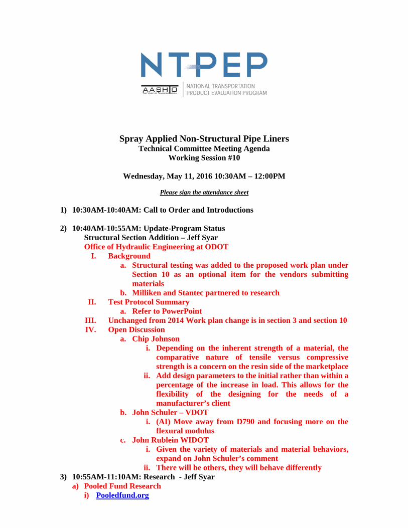
Spray Applied Non-Structural Pipe Liners Technical Committee Meeting Agenda Working Session #10 Wednesday, May 11, 2016 10:30AM – 12:00PM Please sign the attendance sheet 1) 10:30AM-10:40AM: Call to Order and Introductions 2) 10:40AM-10:55AM: Update-Program Status Structural Section Addition – Jeff Syar Office of Hydraulic Engineering at ODOT I. Background a. Structural testing was added to the proposed work plan under Section 10 as an optional item for the vendors submitting materials b. Milliken and Stantec partnered to research II. Test Protocol Summary a. Refer to PowerPoint III. Unchanged from 2014 Work plan change is in section 3 and section 10 IV. Open Discussion a. Chip Johnson i. Depending on the inherent strength of a material, the comparative nature of tensile versus compressive strength is a concern on the resin side of the marketplace ii. Add design parameters to the initial rather than within a percentage of the increase in load. This allows for the flexibility of the designing for the needs of a manufacturer’s client b. John Schuler – VDOT i. (AI) Move away from D790 and focusing more on the flexural modulus c. John Rublein WIDOT i. Given the variety of materials and material behaviors, expand on John Schuler’s comment ii. There will be others, they will behave differently 3) 10:55AM-11:10AM: Research - Jeff Syar a) Pooled Fund Research i) Pooledfund.org
Transcript of Spray Applied Non-Structural Pipe Liners - AASHTO - … … · Spray Applied Non-Structural Pipe...
Spray Applied Non-Structural Pipe Liners Technical Committee Meeting Agenda
Working Session #10
Wednesday, May 11, 2016 10:30AM – 12:00PM
Please sign the attendance sheet 1) 10:30AM-10:40AM: Call to Order and Introductions 2) 10:40AM-10:55AM: Update-Program Status
Structural Section Addition – Jeff Syar Office of Hydraulic Engineering at ODOT
I. Background a. Structural testing was added to the proposed work plan under
Section 10 as an optional item for the vendors submitting materials
b. Milliken and Stantec partnered to research II. Test Protocol Summary
a. Refer to PowerPoint III. Unchanged from 2014 Work plan change is in section 3 and section 10 IV. Open Discussion
a. Chip Johnson i. Depending on the inherent strength of a material, the
comparative nature of tensile versus compressive strength is a concern on the resin side of the marketplace
ii. Add design parameters to the initial rather than within a percentage of the increase in load. This allows for the flexibility of the designing for the needs of a manufacturer’s client
b. John Schuler – VDOT i. (AI) Move away from D790 and focusing more on the
flexural modulus c. John Rublein WIDOT
i. Given the variety of materials and material behaviors, expand on John Schuler’s comment
ii. There will be others, they will behave differently 3) 10:55AM-11:10AM: Research - Jeff Syar
a) Pooled Fund Research i) Pooledfund.org

ii) Commitment Required = $125K (5 DOT’s at $25k each) (1) Current partners are: Ohio, New York, and Pennsylvania. (2) Need two other partners to complete funding
iii) Develop structural design equations for spray applied liners iv) Recommend material lab tests to perform on resin and cementitious
materials v) Recommend durability test to perform in the lab vi) State funding match has been waived by the FHWA
4) 11:15AM-11:30AM: Millikan Research Presentation
a) Miliken Geopolymers (Cementitious liner) Pipe Testing Results i) NTPEP - May 11, 2016 ii) Create a method for the best method for design predictability results iii) Test project funded by Ontario and the transportation industry
(1) Should the culverts be removed or rehabilitated? (2) Queens University was the host lab- Dr. Ian Moore (3) Load tested metal pipe with significant invert loss in soil cell that had
cementitious spray applied liner installed iv) Malayasia Testing results available v) La Tech testing
(1) Currently in the process of acquiring the remainder of the testing data
(2) 18 pipe samples tested, compared to 5 models used by various engineers in the industry
(3) Applied spray applied liner to the following material types: (a) Reinforced concrete pipe (b) Corrugated metal pipe (c) Cardboard sonotube
5) 11:30AM-11:45AM: Questions and Open Discussion
a) Still analyzing the data on the cardboard sonotube lining b) A lot of the pipes being lined are pipe arches. This is why the distributed
beam design approach was favored by Milliken c) John Rublein WIDOT
i) Variability in tested behavior from empirical analysis (1) Issue: if you don’t have consistent boundary conditions, then the
ability to predict based on reproducible research is not easily attained ii) Rourke’s model, used currently by industry, works on the foundation of
uniform loading. Uniform loading is not a realistic way to bound your analysis
d) Recommendation was made to add a parallel plate test to the structural portion for resin based materials that may fail under buckling (ie: flexural) versus cracking. i) Chip Johnson (Spray Roq) indicated that their material is capable of
being sprayed onto cardboard sonotube. ii) Chip Johnson indicated Spray Roq material fails via cracking iii) John Rublein indicated that other resin based material may not fail
under cracking

6) 11:45AM-11:50AM: Action Items for 2016-2017 a) Add parallel plate test for resin based materials to test under structural section
of workplan b) Send out the work plan for voting with the addition of the structural portion c) (AI) Identify the testing based on the failure mode for future evaluations
i) D-Load would apply to Cementitious and Geopolymers ii) Cardboad Sonitude would be applicable for Resin based material that fail
under buckling d) Implement a model that takes slope interactions into account- (ie: knee of the
curve to indicated failure) e) Setup the next quarterly conference call as a follow-up to this meeting

w w w. t r a n s p o r t a t i o n . o h i o . g o v1
Structural Testing for Spray Applied Liner
Jeffrey E. Syar, P.E.Administrator, Office of Hydraulic Engineering

2
BackgroundStructural testing was added to the proposed work plan under Section 10 as an optional item for the Vendors submitting materials
Testing is based on research that was performed by J. Royer (Milliken) and E. Allouche (Stantec) and presented at the 2016 North American Society for Trenchless Technology No-Dig Show
2016 NTPEP – Spray Applied Liners

3
Test Protocol SummaryD-load testing of reinforced concrete pipes to the 0.01 inch
Repair of the D-load tested reinforced concrete pipes to the manufacturer’s recommended thickness to restore strength
Repair of the D-load tested reinforced concrete pipe to the manufacturer’s recommended thickness plus ½ inch and plus 1 inch
2016 NTPEP – Spray Applied Liners

4
Test Protocol SummaryD-load testing of repaired reinforced concrete pipes to the 0.01 inch and to the ultimate load
Test uses 6 reinforced concrete pipes (D-load 1000) at 48 inch diameters
8 foot sticks of pipe could be cut to 4 foot sections, reducing the number of sticks required if it’s cost effective and could still be D-load tested
2016 NTPEP – Spray Applied Liners

5
Pooled Fund Research
2016 NTPEP – Spray Applied Liners

6
Pooled Fund ResearchStructural Design Methodology for Spray Applied Pipe Liners in Gravity Storm Water Conveyance Conduits
Anticipated to take 12 months to complete
Ohio is the Lead state with the following partners: Pennsylvania and New York
Looking for two more DOT partners
2016 NTPEP – Spray Applied Liners
7
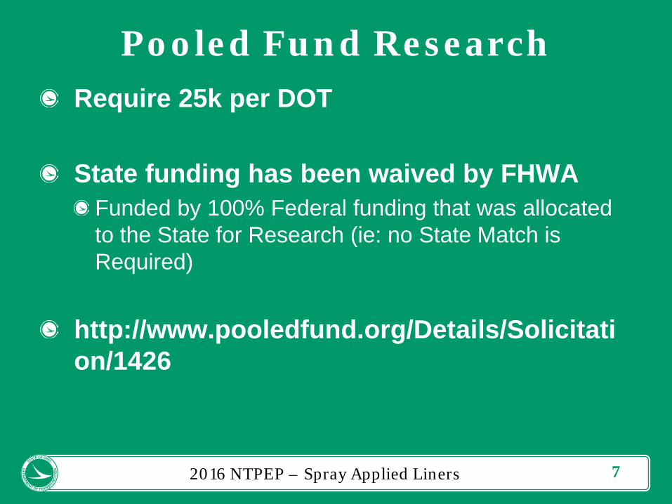
Pooled Fund ResearchRequire 25k per DOT
State funding has been waived by FHWAFunded by 100% Federal funding that was allocated to the State for Research (ie: no State Match is Required)
http://www.pooledfund.org/Details/Solicitation/1426
2016 NTPEP – Spray Applied Liners

8
Objectives of ResearchRecommend a design methodology for both cementitious and resin based spray applied pipe liners for structural rehabilitation of gravity storm water conveyance conduits.
Recommend a laboratory test method to verify the proposed structural design for conduits that have been rehabilitated using the spray applied pipe liner technology.
2016 NTPEP – Spray Applied Liners

9
Objectives of ResearchRecommend an accelerated laboratory methodology to determine the liner material durability.
Recommend laboratory material testing for both cementitious and resin based materials.
2016 NTPEP – Spray Applied Liners

10
Scope of WorkReview multiple vendor suggested structural design methodologies for cementitious and resin based pipe liners. Ensure a minimum number of 4 vendors for cementitious and 4 vendors for resin based materials are solicited for input.
Review the Cured In Place (CIPP) design methodology outlined in ASTM F1216-09, Appendix X.1, equation X1.3. Review the design equations, variables, and assumptions to determine if the methodology is applicable for spray applied liners.
Review completed and active research that pertains to spray applied pipe liners.
2016 NTPEP – Spray Applied Liners

11
Scope of WorkSurvey US State DOT’s and Canadian Agencies to identify use and inspect a field installation of resin material and cementitious material.
Recommend a structural design methodology for cementitious and resin based spray applied liners that includes:
LRFD Live and Dead LoadsHost Conduit Conditions and Site Parameter assumptionsPipe Liner Material Properties
Develop an Excel Spreadsheet to calculate the required thickness for a cementitious and resin based spray applied liner pipe.
2016 NTPEP – Spray Applied Liners

12
Scope of WorkRecommend a laboratory test method to verify the structural design for conduits that have been rehabilitated using the spray applied pipe liner technology.
Recommend an accelerated laboratory methodology to determine the liner material durability.
Recommend laboratory material testing for both cementitious and resin based materials.
2016 NTPEP – Spray Applied Liners

13
Questions?
2016 NTPEP – Spray Applied Liners

Milliken GeopolymersPipe Testing Results
NTPEP- May 11th 2016

Structural Testing:407 Hwy Culverts
Queen’s University – Prof. Ian Moore
Testing Completed November 2013

Queen’s University Testing: Overview
• Damaged and deteriorated CMP culverts were excavated from the E407 Toll
Road in Ontario, Canada.
• Two test culverts were assembled, buried and tested.
• The two culverts were then repaired with GeoSpray geopolymer mortar lining
with nominal thickness of 50.8 mm (~2 inches) and 76.2 mm (~3 inches).
• Testing of the culverts was performed under single and double axle loads with
buried depths of 1200 and 2100 mm (~48 and 83 inches) respectively.
• Finally, the culverts were loaded to the maximum available load conditions
1200 kN (~270,000 lbs-force).
Source - Queens University – Ontario Canada – Ian Moore
Measured Response of 2 Deteriorated Metal Culverts Repaired with Sprayed Cementitious Liners

Queen’s University Testing: Instrumentation
Source - Queens University – Ontario Canada – Ian Moore
Measured Response of 2 Deteriorated Metal Culverts Repaired with Sprayed Cementitious Liners

Queen’s University Testing: Time Lapse View
Source - Queens University – Ontario Canada – Ian Moore
Measured Response of 2 Deteriorated Metal Culverts Repaired with Sprayed Cementitious Liners

Queen’s University Testing: Centrifugal Casting
Source - Queens University – Ontario Canada – Ian Moore
Measured Response of 2 Deteriorated Metal Culverts Repaired with Sprayed Cementitious Liners

Queen’s University Testing: Completed Rehab
Source - Queens University – Ontario Canada – Ian Moore
Measured Response of 2 Deteriorated Metal Culverts Repaired with Sprayed Cementitious Liners

Queen’s University Testing: Results
• 50.8 mm (~2 inch) liner thickness:
Initial signs of damage to the culvert under load were first
observed at 650 kN (146,000 lbs-force) or 18% higher than
the fully factored design load of 552 kN (~124,000 lbs-
force)
• 76.2 mm (~3 inch) liner thickness:
Initial signs of damage to the culvert under load were first
observed at 800 kN (~180,000 lbs-force) or 45% higher
than the fully factored design load of 552 kN (~124,000
lbs-force)
• Full report is now available.
Source - Queens University – Ontario Canada – Ian Moore
Measured Response of 2 Deteriorated Metal Culverts Repaired with Sprayed Cementitious Liners

Sirim QAS RCP Testing
Malaysia – Completed December 2013

Sirim QAS RCP Testing: Experimental Overview
• 4 new RCP pipes 1.7 m (~67 inch) outer diameter, 1.5 m (~59 inch) inner
diameter with a wall thickness of 200 mm (~8 inch) and 1 m in length (~ 39
inch) were coated with GeoSpray geopolymer mortar under the following
conditions:
» Sample 1 – Control Pipe – No Coating
» Sample 2 – 50 mm (~2 inch) nominal coating
» Sample 3 – 38 mm (~1.5 inch) nominal coating
» Sample 4 – 38 mm (~1.5 inch) nominal coating with additional
reinforced wire mesh
• Test were conducted under the following Malaysian standard
» MS 881: Specification for Precast Concrete Pipes and Fittings
for Drainage and Sewerage.
» Part 3: Specification for pipes and fittings with Ogee Pipes
» Appendix F: Crushing strength test for pipes.
Source - Sirim QAS International Test Report No: 2013-CB4822

Sirim QAS RCP Testing: Experimental Apparatus
• Test Conditions
4 New RCP Test Pipe Samples*
Outer Diameter = 1.7 M (~67 inch)
Wall Thickness = 200 mm (~8 inch)
Inner Diameter = 1.5 M (~59 inch)
Length = 1M (~39 inch)
*Coated with GeoSpray geopolymer
Source - Sirim QAS International Test Report No: 2013-CB4822

Sirim QAS International Testing
• Test Results
Source - Sirim QAS International Test Report No: 2013-CB4822
Sample 1 Control Pipe – No Coating
Sample 2 50 mm (~2 inch) nominal
coating
First Crack +122%; UL +268%
Sample 3 38 mm (~1.5 inch) nominal
coating
First Crack +98%; UL +209%
Sample 4 38 mm (~1.5 inch) nominal
coating with additional
reinforced wire mesh
First Crack +24%; UL +277%

La Tech TTCDesign Model Testing
Comparative Engineering Models

La Tech – TTC: Experimental Outline
The goal of the project was to validate proposed engineering
methodologies for structural rehabilitation of large diameter pipes
with experimental data.
This study tested the effects of:
Liner Thickness
Pipe Diameter (24” – 48”)
Ovality
Pipe Type (RCP, CMP, Cardboard)
All RCP pipes were pre-broken prior to repair.
Source – NASST No DIG 2016, Dallas TX – Paper No WM-T6-03 (Royer & Allouche)

La Tech – TTC: Experimental Parameters
Each 8ft Section of RCP had the collar removed and then was cut
approximately in half.
Source – NASST No DIG 2016, Dallas TX – Paper No WM-T6-03 (Royer & Allouche)

All tests were performed under the ASTM C497 “D-Load” method.
La Tech – TTC: D-Load Testing Standard
Source – NASST No DIG 2016, Dallas TX – Paper No WM-T6-03 (Royer & Allouche)

Each pipe was then pre-stressed until a D-Load crack was present in
the crown, invert and the external side of both spring-lines
La Tech – TTC: Experimental Parameters
Source – NASST No DIG 2016, Dallas TX – Paper No WM-T6-03 (Royer & Allouche)

The full suite of rehabilitated pipes
La Tech – TTC: Experimental Parameters

The experimental apparatus included the ability to use video
monitoring of the shear stresses in the structure during loading
La Tech – TTC: Experimental Parameters
Source – NASST No DIG 2016, Dallas TX – Paper No WM-T6-03 (Royer & Allouche)

La Tech – TTC: Experimental Parameters
• July 21, 2014
Source – NASST No DIG 2016, Dallas TX – Paper No WM-T6-03 (Royer & Allouche)

La Tech – TTC: New vs Rehabilitated Pipe Curves

La Tech – TTC: RCP Test Matrix with Results
Pipe OD Pipe ID LengthLiner
ThicknessD-Load D-Load
Deflection
@ D-Load
(inch) (inch) (ft) (inch) (lbs) (psi) (in)
RCP 26.5 24.0 3.7 0.00 11700 75 0.24
RCP 26.5 24.0 3.7 0.00 17400 112 0.19
RCP 39.0 36.0 3.7 0.00 12800 82 0.32
RCP 52.0 48.0 3.7 0.00 18000 116 0.26
RCP 52.0 48.0 3.7 0.00 20700 133 0.24
RCP 26.5 24.0 3.7 0.66 12800 82 0.41
RCP 26.5 24.0 3.7 0.66 10800 69 0.26
RCP 26.5 24.0 3.7 1.33 21700 140 0.37
RCP 26.5 24.0 3.7 1.33 15100 97 0.32
RCP 39.0 36.0 3.7 1.00 15100 97 0.38
RCP 39.0 36.0 3.7 1.00 17500 113 0.38
RCP 39.0 36.0 3.7 1.50 21000 135 0.38
RCP 39.0 36.0 3.7 2.00 20300 131 0.42
RCP 39.0 36.0 3.7 2.00 25500 164 0.60
RCP 52.0 48.0 3.7 1.33 16000 103 0.36
RCP 52.0 48.0 3.7 1.33 18700 120 0.34
RCP 52.0 48.0 3.7 2.66 28500 183 0.46
RCP 52.0 48.0 3.7 2.66 35800 230 0.52
Pipe Type

P
MA
r
𝑐 =𝑡
2
Moment M=I/(c*SF)
I = t3/12
But do we really know where the neutral axis is?
It is more conservative to assume that it is not at
the mid-point of the liner but at the interface so we
will assume c=t
Moment = t2/(12*Sf)
EL – Elastic Modulus
SF – Flexural Strength
ST – Tensile Strength
N – Safety Factor
C – Ovality Reduction Factor (ASTM F-1216)
P – Total Load
μ – Poisson's Ratio
La Tech – TTC: Design Model Assumptions
𝑀𝑐
𝐼
Source – NASST No DIG 2016, Dallas TX – Paper No WM-T6-03 (Royer & Allouche)

Assumes Ends are held constrained at distance L
La Tech – TTC: Model 1 – Uniform Lateral Pressure
Source – Roark’s Formulas for Stress and Strain – Young et. al.

Moment at Invert
Is Maximum
Using the relation
Where w is the crack width
Engineers have suggest w = 0.01 & 0.0625
La Tech – TTC: Model 2 – Cracking
Source – Structural Mechanics of Buried Pipes – Watkins & Anderson

The resultant solution for this case is:
La Tech – TTC: Model 3 – Circular Arch with Beam Load
Source – Structural Mechanics of Buried Pipes – Watkins & Anderson

This is in the form of a quadratic equation
with 4 roots only 1 is real and positive.
La Tech – TTC: Model 4 – Baz-Cao Scaling
Source – Size Effect in Brittle Failure of Unreinforced Pipes – ACI Journal May-June 1966

• Each RCP pipe was preloaded and then rehabilitated and then loaded
again.
• The D-Load Values were scaled with the bedding factor Bf – We assumed
Type IV bedding (Bf = 1.5) (Source: Concrete Pipe Design Manual).
• The following physical properties measured by a third party certified
laboratory were used as the values for the material in the models.
Property Test Method Duration Value
Compression Strength ASTM C109 28 Day 8000 psi
Flexural Strength ASTM C78 28 Day 1800 psi
Elastic Modulus ASTM C469 28 Day 5,800,000 psi
Aggregate Size ASTM C33 2.38 mm
Poisson Ratio ASTM C469 28 Day 0.19
Tensile Strength ASTM C307 28 Day 850 psi
La Tech – TTC: Evaluating the Models against Data
Source – NASST No DIG 2016, Dallas TX – Paper No WM-T6-03 (Royer & Allouche)

Source – NASST No DIG 2016, Dallas TX – Paper No WM-T6-03 (Royer & Allouche)
La Tech – TTC: Data Comparison to Model Predictions – 24”

Source – NASST No DIG 2016, Dallas TX – Paper No WM-T6-03 (Royer & Allouche)
La Tech – TTC: Data Comparison to Model Predictions – 36”

Source – NASST No DIG 2016, Dallas TX – Paper No WM-T6-03 (Royer & Allouche)
La Tech – TTC: Data Comparison to Model Predictions – 48”

Source – NASST No DIG 2016, Dallas TX – Paper No WM-T6-03 (Royer & Allouche)
La Tech – TTC: Real World Field Conditions

Source – NASST No DIG 2016, Dallas TX – Paper No WM-T6-03 (Royer & Allouche)
La Tech – TTC: Liner Thickness – Beam Load Model
This model give good representation of the data and is more
conservative as pipe size increase under typical loads

This model is less conservative at typical field conditions a pipe
diameter increases.
Source – NASST No DIG 2016, Dallas TX – Paper No WM-T6-03 (Royer & Allouche)
La Tech – TTC: Liner Thickness – Bazant-Cao Model

• 18 RCP Pipe Samples were tested and evaluated.
• They were compared to 5 models that have been used for design by various
engineers in the industry.
• The 0.01 Crack Model is the most conservative with a significant over design in
all cases (well above the safety factor of 2.0).
• The Bazant – Cao Model is generally conservative and predictive for pipes in
the size range tested, but becomes less conservative as the pipes increase in
size greater than 48”.
• The Distributed Beam over a Partial Ring Model is less conservative at lower
pipe sizes but becomes predictive and more conservative as the pipe size
increases.
• All 3 of these models give reasonable predictions in the range of typical design
pressures (below 50 psi).
Source – NASST No DIG 2016, Dallas TX – Paper No WM-T6-03 (Royer & Allouche)
La Tech – TTC: Conclusions

First Name Last Name Title Email Phone PresentDarby Clayton [email protected] 304-558-9567 1Kean Ashurst [email protected] 859-257-7319 1Doug Gesso [email protected] 502-782-4881 1Katheryn Malusky [email protected] 202-624-3695 1Kyle Larson [email protected] 785-291-3825 1Robert Meinzer [email protected] 1David Keaffaber Midwest Region Manager [email protected] 317-306-6595 1Maribel Wong [email protected] 202-624-3559 1Natalie Roskam Ncdot [email protected] 1Vince Glick [email protected] 202-624-7743 1Brennan Roney [email protected] 404-608-4816 1David Kotzer [email protected] 303-398-6566 1Sabra Gilbert-Young [email protected] 775-888-7894 1Jack Cowsert [email protected] 919-329-4030 1Ting Nahrwold [email protected] 317-232-5080 1John Rublein [email protected] 608-246-7953 1Guohua Lian [email protected] 404-608-4824 1Chip Johnson [email protected] 1Kidada Dixon [email protected] 334-353-6940 1John Schuler [email protected] 804-328-3140 1Rodney Klopp [email protected] 717-787-7827 1Andy Bennett [email protected] 517-322-5043 1Allen Gallistel [email protected] 651-366-5545 1Karen Byram [email protected] 850-414-4353 1Mike Paipal Field Engineer [email protected] 1Jeffrey Syar [email protected] 614-275-1373 1Rodrigo Herrera [email protected] 850-414-4377 1Richard Douds [email protected] 404-608-4805 1Douglas Gayne [email protected] 207-624-3268 1Mario Paredes Senior Research Engineer [email protected] 352-231-0992 1Therese Kline [email protected] 517-241-0082 1