SPM Hose Back Flushing Method 2015
26
Subsea and Floating Hose Flushing Procedure for Catenary Anchor Leg Mooring (CALM-Buoy) SPM-1 (B) Steep Wave Conf. TPO- Fujairah “It consists of a buoy anchored by 6 chains extending in catenaries to anchor points on seabed” 1 30/10/2015
-
Upload
capt-khaldon-al-shaibani -
Category
Documents
-
view
1.479 -
download
88
Transcript of SPM Hose Back Flushing Method 2015

Subsea and Floating Hose Flushing Procedure for Catenary Anchor Leg
Mooring (CALM-Buoy) SPM-1 (B) Steep Wave Conf. TPO-
Fujairah“It consists of a buoy anchored by 6 chains extending in catenaries to anchor points on
seabed”1 30/10/2015

SPM PIPING SYSTEM DIAGRM
2 30/10/2015

1. ADCO will submit the plan of anticipated operation for the Back Flushing Works to the Port’s Safety Officer who shall arrange their Pollution Boat to have rounds during the back flushing operation.
2. ADCO will have a formal meeting one month prior to the required operation with HM and also PoF Operations to finalize the Method statement and advise them of our confirmed plan.
3. Necessary inward out ward clearance for marine loading hoses from the POF customs.
3 30/10/2015

FLOATING /SUBSEA HOSES FLUSHING / ASSEMBLING/ INSTALLATION
Reference1. ADCO Marine Manual-Operation and Maintenance. IRSHAD’s Diving Permit (DV007-Rev07-Sep 15).
2. OPCO’s Standard Back Flushing Procedures. ADCO HSE/HSEMS Risk Register. 30-99-89-2601.
3. ADCO Task Risk Assessment Matrix. Single Point Mooring System HAZOP.
4. Port Of Fujairah Rules.
5. Ship-to-Ship transfer Guide latest edition as recommended by ICS & OCIMF.
6. Guidelines for the Handling, Storage, Inspection and Testing of hoses in the Field”, edition 1995 and manufacturer's recommendations.
Resources Available VM Leader & Two Line boats. Flatbed utility trailer- available @Marine Warehouse (MOL). Torque wrench for loosening of the flange bolts.
Resources Required- Budget 2016-6820/6990 Marine Maintenance (USD150K)I. Laydown Area Inside Port of Fujairah ( for storage of the Hoses).
II. (Hire- Slop Barge-Receivable Rate: 300m3/hr) to take Back Flushing cargo ( 5,000bbls~600m3 Liguid).
III. Mobile Crane Telescopic 20Ton & 2 Forklifts (5Ton).
IV. Certified 8” Oil Transfer Rubber Hose with length 80~90m & reducer 8”x16”.4 30/10/2015

PLEM LAYOUT - Vent/Flush Valves ( BL-1102A-BL-1102B & XV1801-1802)
5 30/10/2015

CL1 & CL2-Rail Hoses onboard VM Leader
6 30/10/2015
FLOATING /SUBSEA HOSES FLUSHING OVERVIEW
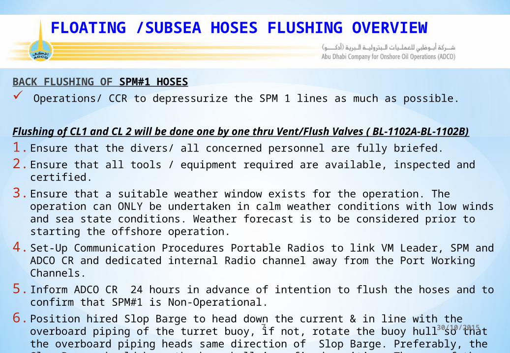
BACK FLUSHING OF SPM#1 HOSES Operations/ CCR to depressurize the SPM 1 lines as much as possible.
Flushing of CL1 and CL 2 will be done one by one thru Vent/Flush Valves ( BL-1102A-BL-1102B)1. Ensure that the divers/ all concerned personnel are fully briefed.
2. Ensure that all tools / equipment required are available, inspected and certified.
3. Ensure that a suitable weather window exists for the operation. The operation can ONLY be undertaken in calm weather conditions with low winds and sea state conditions. Weather forecast is to be considered prior to starting the offshore operation.
4. Set-Up Communication Procedures Portable Radios to link VM Leader, SPM and ADCO CR and dedicated internal Radio channel away from the Port Working Channels.
5. Inform ADCO CR 24 hours in advance of intention to flush the hoses and to confirm that SPM#1 is Non-Operational.
6. Position hired Slop Barge to head down the current & in line with the overboard piping of the turret buoy, if not, rotate the buoy hull so that the overboard piping heads same direction of Slop Barge. Preferably, the Slop Barge should keep the buoy hull in a fixed position. The use of the turret locking device is also possible.
7 30/10/2015

Assembling of Certified 8” Oil Transfer Rubber onboard VM LEADER CL1 String- Back Flushing1. 8” hoses will be loaded on SHAH-1 from the Harbour.
2. Boat SHAH-1 will deliver 8” of 8 numbers Hoses to “VM Leader”. Then diving team will assemble it.
3. Upon assembling will carry on a pressure test of the hose onboard “VM Leader”.
4. Floatation collars jackets will be secured on Hose number 4, 5 & 6 for floatation and to give Lazy S shape to achieve optimum flow of the Flushing while flushing Ops.
5. Divers will dive to install & secure GuideWire and down line at PLEM 8” Vent/Flush Valve. BL-1102A-BL-1102B
6. By utilizing “VM Leader” crane and tugger winch 8” hose will be slide down on GuideWire.
7. Divers will connect the 8” hose on 8” Vent/Flush Valve @ PLEM.
8. One end of the 8” hose will be passed to hired Slop Barge to connect it on (8’) Manifold.
9. Divers will open 8” Vent/Flush Valve on PLEM and diver will come back to surface.
10. Upon connection of the floating Rail End Hose to the (16”)Flushing Manifold, Vessel’s Engineer will make sure that the Fire Pump is ready for pumping.
CL2 String Back Flushing method will be in the same manner as CL1 String.
8 30/10/2015

FLOATING /SUBSEA HOSES FLUSHING OVERVIEW7. Install mooring ropes between the Slop Barge and the turret buoy, the distance between them being controlled by the Slop Barge.8. Ensure that, Fujairah-SPC Team has been informed about the back flush works. And the Oil Contents in the Slop Barge.
Ensure that the product piping & floating hose strings are relieved to atmospheric pressure, check with valve BL-1107C & BL-1107D (8”Vent/Flush Connection @ turret hull deckhouse location.
Ensure that turret buoy valves ( XV-1601/1602) are reset according to the valve setting (BES Doc.No.ADCO-G-800-MA-0090-101/Rev.2).
Back Flushing of separate Floating /Submarine hose string individually by “VM Leader’s Manifold (16”). Flushing of separate submarine and floating hose string becomes significant in the event of hose change -out. Ensure that the Butterflyvalve (BU-1109A) in the inner strings is (open). Care must be taken to avoid damaging the floating hose string once overboard in the seawater.
9 30/10/2015

Phase 1-Inner Strings (CL1): 27 numbers of Floating Hoses + 8 numbers of Submarine Hoses - back flush works thru BL-1102A (8” Vent/Flush connection valve with external certified 8” Oil Transfer Rubber Hose)- PLEM 24” actuator Valve XV 1801- (Closed) to isolate the offshore 48” pipeline towards MOL..
I. Back Flush Quantity (CL1) 97m3 + 25 m3=122m3~770bbls.II. Minimum Back Flushing Cycle Works : 3 Cycle (3 x 770)= 2,310bbls.III. BL-1105A & XV1601 (Open).IV. Divers to connect 8” Oil Transfer Rubber Hose on BL -1102A 8” Flush connection valve (PLEM location) will be
connected to the hired Slop Barge Manifold-( 8”x16”).V. Ensure that the Butterfly valve (BU-1109A) in the inner strings is (open).
Phase 2-outer Strings (CL2): 28 numbers of Floating Hoses + 8 numbers of Submarine Hoses - back flush works thru BL-1102B (8” Vent/Flush connection valve with external certified 8” Oil Transfer Rubber Hose)- PLEM 24” actuator Valve XV 1802- (Closed) to isolate the offshore 48” pipeline towards MOL.
I. Back Flush Quantity (CL2) 101m3 + 25 m3=126m3~793bbls.II. Minimum Back Flushing Cycle Works : 3 Cycle (3 x 793)= 2,3790bbls.III. BL1105b & XV1602 (Open).IV. Divers to connect 8” Oil Transfer Rubber Hose on BL-1102B 8” Flush connection valve (PLEM location) will be
connected to the hired Slop Barge Manifold ( 8”x16”).V. Ensure that the Butterfly valve (BU-1109B) in the outer strings is (open).10 30/10/2015

FLOATING /SUBSEA HOSES FLUSHING OVERVIEW
The Floating Hose strings (inner CL#1) Rail end hose to be connected on “VM Leader” Flushing Manifold- (8”16”). Pre-decided Communication to be established between Slop Barge & “VM Leader” for Flushing start-up and the Slop Barge
to be ready to take the Back Flush. Start with low rate Pumping of the flush medium cleaning the floating hose strings gradually increase to flow rate until
maximum (1) Pump Capacity 1450 m3 on board “VM Leader”.
Sample the back flush from the hired Slop Barge for Cleanness ensure that Port of Fujairah (Safety Officer) attend as witness.
Once the “3 cycle” of the Flushing Works of the inner strings CL#1 is completed by ensuring the flushing samples is only water, shut deck house valves BL-1105A and turret valve XV1601 of the inner CL#1.
Same procedure to be followed for the second String for Flushing Works shut deck house valves - BL-1105B & XV1602 of the outer strings CL#2.
Hired Slop Barge – Separate call off order to be made Slop Barge scuppers to block off and the barge to be surrounded by Oil Boom to avoid any oil pollution spreading in the event of a hydrocarbon release . Hence the Oil Spill team will be ready
in all aspect to meet any eventuality. Adequate Oil Spill Absorbents to be available on the “VM Leader” during hose disconnection, and a drip tray to be underneath each hoses break when disconnecting.
11 30/10/2015

GENERAL OVERVIEW - OPERATIONAL SYSTEM.
12 30/10/2015

Subsea and floating hose disconnection procedure for
Catenary Anchor Leg Mooring (CALM-Buoy) SPM-
1 (B) Steep Wave Conf. “Take Precaution not to damage the Floating Hose Strings”
13 30/10/2015

Prior to commencing the disconnection, the following factors should be considered:
1. The first-off-buoy hose is fully reinforced with reserve buoyancy of approx.5% additional floats required to
keep the hose above water during the offshore tow as the hose will be partly submerged, if no additional floats
are used.
2. Safety precautions are to be taken for ensuring that the divers is not harmed by unexpected dangerous situation
Hence TRA is MUST.
3. When disconnected, ensure that the hose bend radius stay within the manufacturer's limits (Submarine Hose-
2.03m & Floating Hose-3.04m).
4. Speed of the towing vessel with floating hose string is max.5 knots.
5. Watch keeper should be placed and watch the tow operation at all times.
PREPARATION OF SPM FOR HOSE EXCHANGE
14 30/10/2015

“VM Leader” Positioning Astern to face mooring arm of buoy
15 30/10/2015

SPM to be prepared for hoses exchange as follow:
Mooring hawser and all rigging to be completely removed from the SPM. Floating hose pick-up chain & snubbing chain assembly to be removed as well as the winker lights to be removed. The securing bolts to be installed in the Safety Marine Break Away Couplings as a safety factor to prevent any damage or
activation.
.
16 30/10/2015
FLOATING HOSE DISCONNECTION & PREPARATION FOR TRANSPORTATION
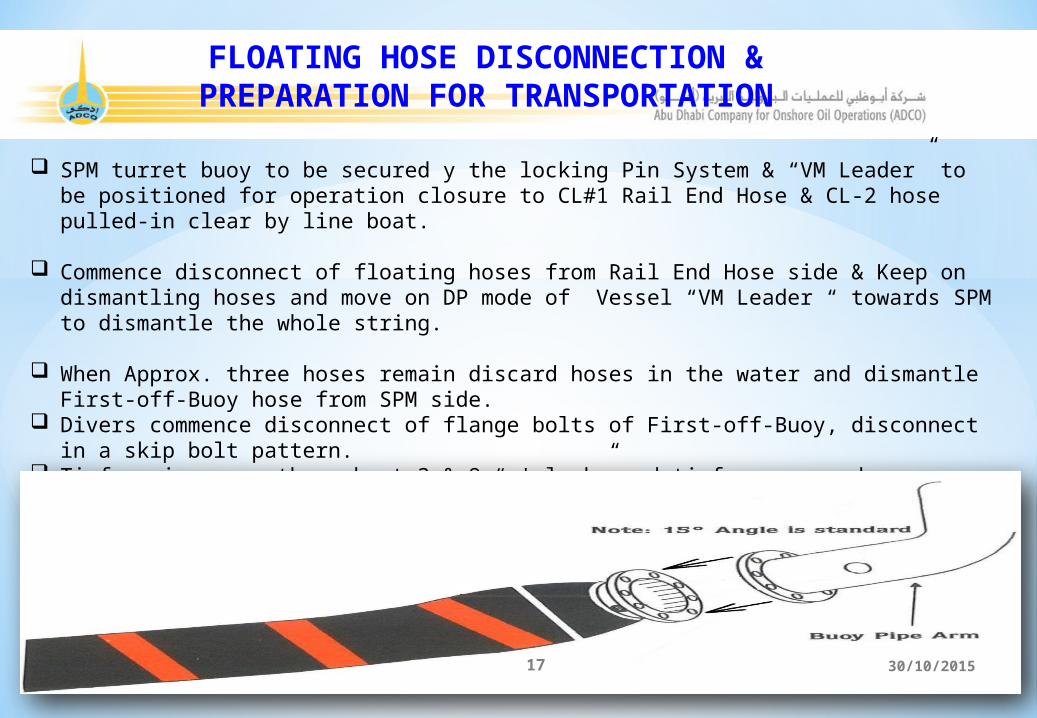
SPM turret buoy to be secured y the locking Pin System & “VM Leader” to be positioned for operation closure to CL#1 Rail End Hose & CL-2 hose pulled-in clear by line boat.
Commence disconnect of floating hoses from Rail End Hose side & Keep on dismantling hoses and move on DP mode of Vessel “VM Leader “ towards SPM to dismantle the whole string.
When Approx. three hoses remain discard hoses in the water and dismantle First-off-Buoy hose from SPM side. Divers commence disconnect of flange bolts of First-off-Buoy, disconnect in a skip bolt pattern. Tirfor wires run through at 3 & 9 “o'clock” and tirfors secured. Support buoy floated into position and secured to First-off-Buoy hose at deepest point, to prevent hose sinking after dis-
connection.
17 30/10/2015

FLOATING HOSE DISCONNECTING & TRANSPORTATION
“VM Leader” Crane /Tugger wire attached to the First-off-Buoy hose approx. 1 meter behind flange via belly band strop.
Remaining bolts removed and tirfor wires slackened.
Connect Crane/ Tugger to the First-off-Buoy hose for lifting it to on “VM Leader” Main Deck. Disconnect First-off-Buoy Hose and the succeeding hose.
All dismantled hoses would be transported by utilizing SHAH-1 Boat to the Fujairah Harbour.
On arrival of the SHAH-1 Boat at Fujairah Harbour, the Hoses would be offloaded by Hired 20TON Mobile Crane for further transportation to store/ hired designated laydown area.
A second hose string (CL2) can be disconnected in the same manner as the First String.
18 30/10/2015
Subsea and Floating Hoses installation Procedure for
Catenary Anchor Leg Mooring (CALM-Buoy) SPM-1 (B) Steep
wave Conf.
“Manufacturers' representatives MUST attend the Installation Operation”
19 30/10/2015

ASSEMBLING HOSES
Floating hoses to be assembled in the SPM Area on “VM Leader” Hydrostatic Leak Testing & Visual Inspection
Hoses to be lowered in a controlled manner, using 30Ton Crane of “VM Leader”
20 30/10/2015

FLOATING HOSES ASSEMBLING
Assembly New Floating Hose Strings.
o Upon offloading these hoses onboard “VM Leader”. Hoses will be assembled on the Main Deck and lowered in the seawater one by one with the help of crane and tugger.
o After the floating hose string is completed, the Rail Hose End of the String should remain onboard “VM Leader” in preparation for the “Hydrostatic Leak Testing”. Depending on this Test , the complete floating hose back to the PLEM valves may be tested.
o The “Hydrostatic Leak Testing” should consist of raising the internal pressure in the Hose either to its rated pressure or operating pressure (+50%) whichever is lower, and then holding it for a period of three (3) hours Visual Inspection of Floating Hose & Submarine Hoses should only commence when the pressure has been stabilized.
o After finalising the “Hydrostatic Leak Testing” & depressurization to ZERO of the complete crude oil transfer system, the Rail Tanker Hose of the Floating Hose String can be released into the seawater.
21 30/10/2015

FLOATING HOSES INSTALLATION METHOD
o The buoy hull can be fixed at three (3) different positions to the turret.o Run air hoses from the compressor onboard the line boat to the turret buoy to operate the winch on the turret buoy
deckhouse.o Pass the buoy winch wire thru the sheaves to the hired Slop Barge for connection to the First-off-Buoy hose & winch
the hose until it nears the overboard piping spool.o Pull-in the hose length against the matching flange of the overboard pipe spool and install the gasket & fix all washers,
”Bolts and nuts for tightening of the First-off-Buoy Hose length, the other side of the hose is still onboard “VM Leader” hold by a winch wire.
o 2 x 5 ton Tirfors rigged from SPM to assist aligning flange faces.o CL-1 hose string to positioned alongside of “VM Leader”. o Remove Blind Flange from the First-off-Buoy Hose fitted to the Hose String.o Hose transferred to SPM ‘J’ tube and Tirfor wires passed through 3 & 9 “o'clock” bolt holes.o If requires utilize Vessel crane to align flange faces. Sometimes it may require to provide weights to align and tighten
bottom bolts. Act as situation prevails. o Flange faces pulled together, draw bolts and podgers used to align flange faces.o Lower bolts fitted and tirfor wires draw bolts and podgers removed.o Gasket and remaining bolts fitted.o All bolts tightened by utilising Impact wrench.
22 30/10/2015

UMBILICAL CABLE (104m L)DISCONNECTING
Subsea umbilical cable to be disconnected from the both ends, and ensure that to be Flushing & Filling by Fluid (HW525-MARSTON BENTLEY 205 LTRS)
23 30/10/2015

SUBSEA HOSE DISCONNECTING
Under buoy hose to be secured by rigging arrangements and connected to the Buoy Winch.
“VM Leader” tugger and other rigging to be secured to the subsea hose for better securing.
The under buoy hose flange will then be disconnected by divers. The Blind Flange to be installed temporarily.
The buoy end of the hose to be lowered on appx. 10 m. depth, then secured by rigging arrangement of the “VM Leader” 30Ton Crane. Once the weight transferred, Buoy winch to be disconnected.
The upper end of the string to be hoisted and secured alongside of “VM Leader” and additional floats to the upper hose to be fitted.
The Subsea connection on the PLEM to be disconnected by divers as per the diving procedure.
Disconnected Subsea string then taken on “VM Leader” deck and start dismantling the hoses one by one.
Disconnected hoses then loaded on SHAH#1 to transport Fujairah Harbour Main Quay where these hoses will be offloaded and further transported to the Harbour hired Laydown designated area.
24 30/10/2015

SUBSEA HOSES ASSEMBLING AND CONNECTION
All the new hoses would be transported by utilizing SHAH-1/ Line Boat to “VM Leader” and by the hired Mobile Crane would be utilized to load the hoses on Boat SHAH-1.
Upon offloading these hoses on “VM Leader” Hoses will be assembled on deck and lowered in the seawater one by one with the help of “VM Leader” crane and tuggers.
Once the whole string is assembled the string will be connected as per the procedures. Later pressure test will be carried out.
A second Hose String (CL2) can be connected in the same manner as the First String.
25 30/10/2015
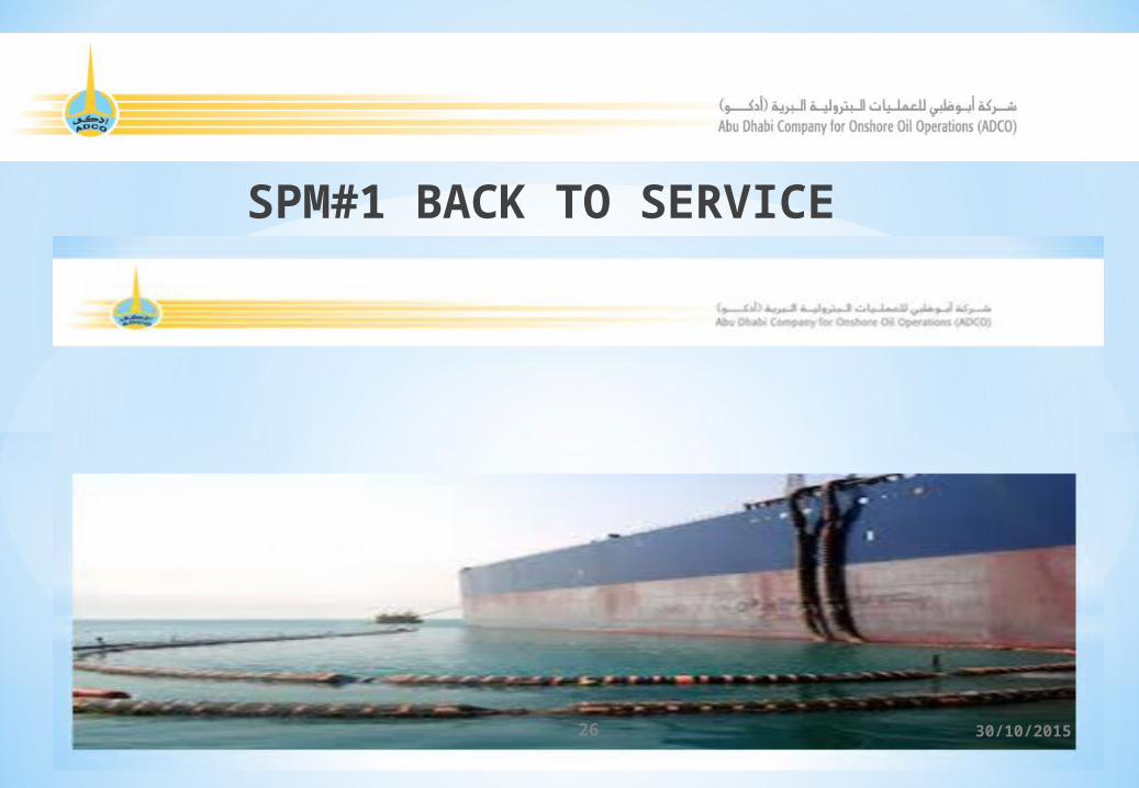
SPM#1 BACK TO SERVICEThank
26 30/10/2015