SPLIT TYPE ROOM AIR CONDITIONER WALL MOUNTED type INVERTER ...SI)ASU18 24... · split type room air...
66
SPLIT TYPE ROOM AIR CONDITIONER WALL MOUNTED type Models Indoor unit Outdoor unit INVERTER SERVICE INSTRUCTION R410A ASU18RLF ASU24RLF AOU18RLXFW AOU24RLXFW
Transcript of SPLIT TYPE ROOM AIR CONDITIONER WALL MOUNTED type INVERTER ...SI)ASU18 24... · split type room air...
SPLIT TYPEROOM AIR CONDITIONER
WALL MOUNTEDtype
Models Indoor unit Outdoor unit
INVERTER
SERVICE INSTRUCTION
R410A
ASU18RLFASU24RLF
AOU18RLXFWAOU24RLXFW
CONTENTS1. DESCRIPTION OF EACH CONTROL OPERATION1. COOLING OPERATION................................................................................................
3. DRY OPERATION.........................................................................................................2. HEATING OPERATION.................................................................................................
5. INDOOR FAN CONTROL..............................................................................................4. AUTO CHANGEOVER OPERATION............................................................................
7. LOUVER CONTROL.....................................................................................................6. OUTDOOR FAN CONTROL..........................................................................................
9. TIMER OPERATION CONTROL...................................................................................8. COMPRESSOR CONTROL..........................................................................................
11. TEST OPERATION CONTROL...................................................................................10. ELECTRONIC EXPANSION VALVE CONTROL........................................................
13. FOUR-WAY VALVE EXTENSION SELECT................................................................12. PREVENT TO RESTART FOR 3 MINUTES ( 3 MINUTES ST ).................................
15. MANUAL AUTO OPERATION ( Indoor unit body operation ).....................................14. AUTO RESTART.........................................................................................................
16. FORCED COOLING OPERATION..............................................................................
18. MINIMUM HEAT OPERATION....................................................................................17. COMPRESSOR PREHEATING..................................................................................
19. ECONOMY OPERATION............................................................................................
21. OFF DEFROST OPERATION CONTROL...................................................................20. DEFROST OPERATION CONTROL...........................................................................
01-0101-0201-0201-0301-0401-0601-0701-0801-0901-1101-11
01-1101-1101-1201-1201-1201-1201-1201-1301-15
22. VARIOUS PROTECTIONS.......................................................................................... 01-16
01-11
2. TROUBLE SHOOTING2-1 ERROR DISPLAY.......................................................................................................
2-1-1INDOOR UNIT AND WIRED REMOTE CONTROLLER DISPLAY ...............................
3. APPENDING DATA
2-1-2 WIRED REMOTE CONTROLLER DISPLAY.............................................................2-2 TROUBLE SHOOTING WITH ERROR CODE............................................................2-3 TROUBLE SHOOTING WITH NO ERROR CODE.....................................................
02-0102-0102-02
3-1 FUNCTION SETTING.................................................................................................3-1-1 INDOOR UNIT........................................................................................................3-1-2 PROCEDURSE TO CHANGE THE FUNCTION SETTING FOR WIRELESS RC..........
03-0103-0103-03
3-3 THERMISTOR RESISTANCE VALUES...................................................................... 03-09
02-0302-23
2-4 SERVICE PARTS INFORMATION.............................................................................. 02-28
3-2 OUTDOOR UNIT PRESSURE VALUE AND TOTAL ELECTRIC CURRENT CURVE............... 03-05
1 . DESCRIPTION OF EACH CONTROL OPERATION
R410A
WALL MOUNTED typeINVERTER
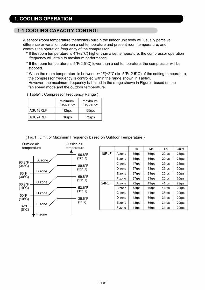
( Fig.1 : Limit of Maximum Frequency based on Outdoor Temperature )
1. COOLING OPERATION
1-1 COOLING CAPACITY CONTROL
A sensor (room temperature thermistor) built in the indoor unit body will usually perceivedifference or variation between a set temperature and present room temperature, and controls the operation frequency of the compressor. * If the room temperature is 4°F(2°C) higher than a set temperature, the compressor operation frequency will attain to maximum performance.
minimumfrequency
maximumfrequency
ASU18RLF 12rps 55rps
ASU24RLF 16rps 72rps
Outside air Outside airtemperature temperature
96.8°F(36°C) A zone93.2°F
(34°C) 89.6°F(32°C)B zone 86°F
(30°C) 69.8°F(21°C)C zone66.2°F
(19°C)D zone
Hi Me Lo QuietA zone 55rps 36rps 29rps 25rpsB zone 55rps 36rps 29rps 25rpsC zone 47rps 36rps 29rps 25rps
18RLF
D zone 37rps 33rps 26rps 20rpsE zone 37rps 33rps 26rps 20rpsF zone 37rps 33rps 26rps 20rps
72rps 49rps 41rps 29rps72rps 49rps 41rps 29rps55rps 41rps 36rps 29rps43rps 36rps 31rps 20rps43rps 36rps 31rps 20rps41rps 36rps 31rps 20rps
A zoneB zoneC zone
24RLF
D zoneE zoneF zone
( Table1 : Compressor Frequency Range )
01-01
E zone
F zone
50°F(10°C)
32°F(0°C)
53.6°F(12°C)
35.6°F (2°C)
* When the room temperature is between +4°F(+2°C) to -5°F(-2.5°C) of the setting temperature, the compressor frequency is controlled within the range shown in Table1. However, the maximum frequency is limited in the range shown in Figure1 based on the fan speed mode and the outdoor temperature.
* If the room temperature is 5°F(2.5°C) lower than a set temperature, the compressor will be stopped.
2. HEATING OPERATION
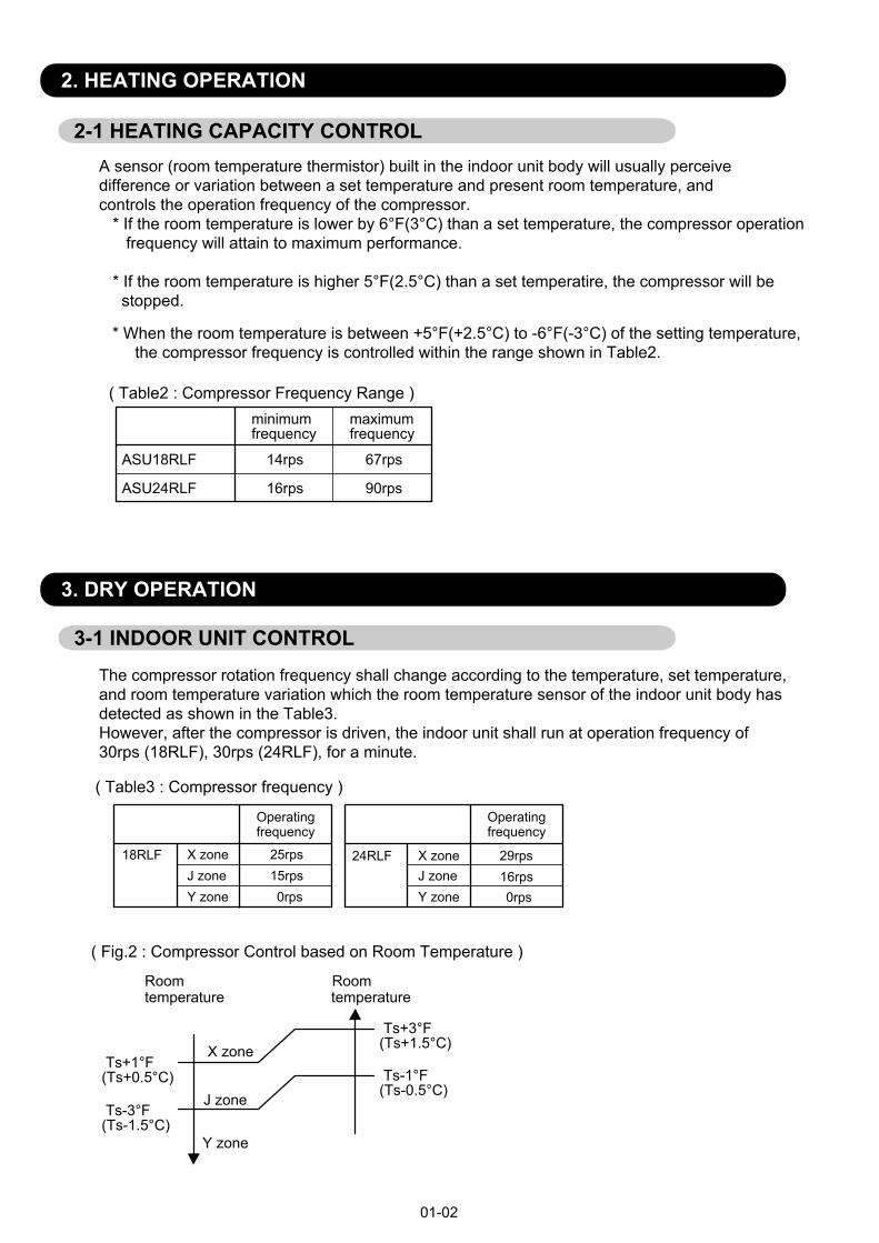
2-1 HEATING CAPACITY CONTROLA sensor (room temperature thermistor) built in the indoor unit body will usually perceivedifference or variation between a set temperature and present room temperature, and controls the operation frequency of the compressor. * If the room temperature is lower by 6°F(3°C) than a set temperature, the compressor operation frequency will attain to maximum performance. * If the room temperature is higher 5°F(2.5°C) than a set temperatire, the compressor will be stopped.
* When the room temperature is between +5°F(+2.5°C) to -6°F(-3°C) of the setting temperature, the compressor frequency is controlled within the range shown in Table2.
( Table2 : Compressor Frequency Range )
01-02
minimumfrequency
maximumfrequency
ASU18RLF 14rps 67rps
ASU24RLF 16rps 90rps
3. DRY OPERATION
3-1 INDOOR UNIT CONTROLThe compressor rotation frequency shall change according to the temperature, set temperature,and room temperature variation which the room temperature sensor of the indoor unit body hasdetected as shown in the Table3. However, after the compressor is driven, the indoor unit shall run at operation frequency of 30rps (18RLF), 30rps (24RLF), for a minute.
Ts+1°F(Ts+0.5°C) Ts-1°F
(Ts-0.5°C) Ts-3°F(Ts-1.5°C)
Ts+3°F(Ts+1.5°C)
( Table3 : Compressor frequency )
( Fig.2 : Compressor Control based on Room Temperature )
Operatingfrequency
25rps15rps0rps
18RLF X zoneJ zoneY zone
Operatingfrequency
J zoneY zone
X zone 29rps16rps0rps
24RLF
Room Roomtemperature temperature
X zone
J zone
Y zone
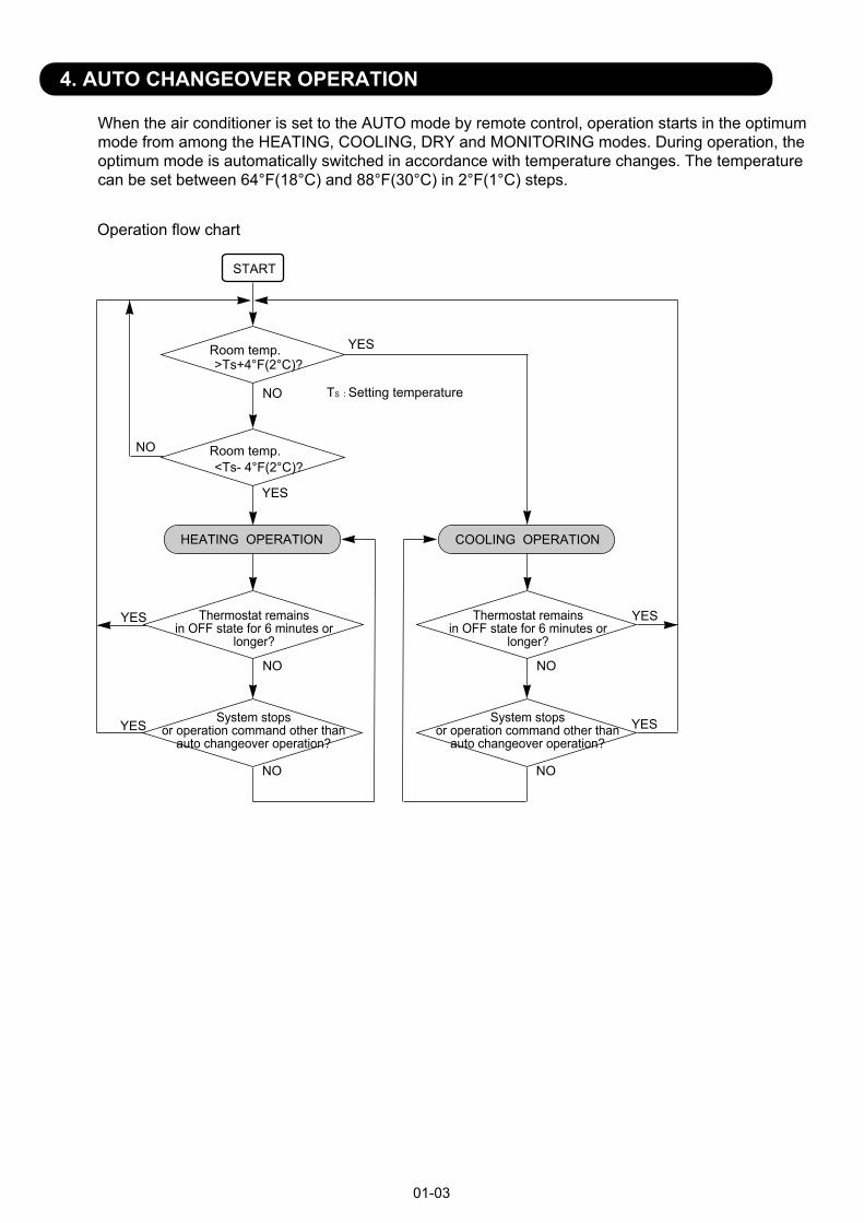
4. AUTO CHANGEOVER OPERATION
01-03
Operation flow chart
START
Room temp.
Room temp.
>Ts+4°F(2°C)?
COOLING OPERATIONHEATING OPERATION
YES
YES
NO
NO
NO
NO
YES
YES
TS : Setting temperature
<Ts- 4°F(2°C)?
Thermostat remainsin OFF state for 6 minutes or
longer?
System stopsor operation command other than
auto changeover operation?
NO
NO
Thermostat remainsin OFF state for 6 minutes or
longer?
System stopsor operation command other than
auto changeover operation?
YES
YES
When the air conditioner is set to the AUTO mode by remote control, operation starts in the optimummode from among the HEATING, COOLING, DRY and MONITORING modes. During operation, theoptimum mode is automatically switched in accordance with temperature changes. The temperaturecan be set between 64°F(18°C) and 88°F(30°C) in 2°F(1°C) steps.
5. INDOOR FAN CONTROL
The airflow can be switched in 5 steps such as AUTO, QUIET, LOW, MED, HIGH, while the indoor fan only runs.When Fan mode is set at (Auto), it operates on (MED) Fan Speed.
01-04
1. Fan speed
2. FAN OPERATION
( Table4 : Indoor Fan Speed )
Operation mode Air flow modeSpeed (rpm)
126011201020900
Cooling/ Fan
Hi
Hi
790680270
1260
Me+Me
Me
Heating
Lo
Lo1020900
Quiet
Quiet
770Dry
S-Lo
X zone : 770J zone : 720
1530132012201020900720270
148012201020900
X zone : 900J zone : 850
Cool air prevention
3. COOLING OPERATIONSwitch the airflow [AUTO], and the indoor fan motor will run according to a room temperature, as shown in Figure3.On the other hand, if switched in [HIGH] [QUIET], the indoor motor will run at a constant airflow of [COOL]operation modes QUIET, LOW, MED, HIGH,as shown in Table4.
( Fig.3 : Airflow change - over ( Cooling : AUTO ) )
When the room temperature risesWhen the room
temperature drops
TR : Room temperatureTs : Setting temperature
TR-Ts > 4°F (2°C)
2°F > TR-Ts(1°C)
4°F > TR-Ts > 2°F (2°C) (1°C)=
TR-Ts > 5°F (2.5°C)
=
3°F > TR-Ts(1.5°C)
5°F > TR-Ts > 3°F(2.5°C) (1.5°C)=
HIGH mode
MED mode
LOW mode
ASU18RLF ASU24RLF
4. DRY OPERATIONRefer to the Table4.During the dry mode operation, the fan speed setting can not be changed.
The maximum value of the indoor fan speed is set as shown in Figure5, based on the detectedtemperature by the indoor heat exchanger sensor on heating mode.(Fig.5 : Cool Air Prevention Control)
01-05
5. HEATING OPERATIONSwitch the airflow [AUTO], and the indoor fan motor will run according to a room temperature,as shown in Figure4.On the other hand, if switched in [HIGH] [QUIET], the indoor motor will run at a constant airflow of [HEAT] operation modes QUIET, LOW, MED, HIGH, as shown in Table4.
6. COOL AIR PREVENTION CONTROL (Heating mode)
( Fig.4 : Airflow change - over ( Heating : AUTO ) )
TR-Ts > -3°F (-1.5°C)
=
-5°F > TR-Ts(-2.5°C)
-3°F > TR-Ts > -5°F(-1.5°C) (-2.5°C)
=
TR-Ts > -2°F (-1°C)
=
-4°F > TR-Ts(-2°C)
-2°F > TR-Ts > -4°F(-1°C) (-2°C)=
When the room temperature rises When the room
temperature drops
TR : Room temperatureTs : Setting temperature
LOW mode
MED mode
MED+ mode
107.6°F (42°C)
86°F (30°C)
93.2°F (34°C)
Indoor heat exchanger temperature Indoor heat exchanger
temperatureHi
Me+
LoCool air prevention
102.2°F (39°C)
98.6°F (37°C)
98.6°F (37°C)
89.6°F (32°C)
82.4°F (28°C)S-Lo
6. OUTDOOR FAN CONTROL
( Table6 : Outdoor fan speed )
* The outdoor fan speed mentioned above depends on the compressor frequency.(When the compressor frequency increases, the outdoor fan speed also changes to the higherspeed. When the compressor frequency decreases, the outdoor fan speed also changes to thelower speed.)
* After the defrost control is operated on the heating mode, the fan speed keeps at the higher speedas table8 without relating to the compressor frequency.
01-06
( Table7 : Outdoor fan speed after the defrost )
1. Outdoor Fan Motor
2. Fan Speed
AC Motor DC Motor
ASU18 / 24RLF
Following table shows the type of the outdoor fan motor. The control method is differentbetween AC motor and DC motor.
( Table5 : Type of Motor )
ASU18RLF 800rpm
Cooling Heating
ASU18RLF
ASU24RLF
D
F
Zone
800/ 620/ 500/ 400
800/ 620/ 550/ 450
900/ 850/ 800/ 620/ 550/ 450
Refer to Fig.6
(rpm)
500/ 320/ 250
G
H
300/ 230/ 200
220/ 200
D
F
850/ 800/ 620/ 500/ 400
500/ 320/ 250
G
H
300/ 230/ 200
220/ 200
Dry
550/ 450
550/ 450
ASU24RLF 900rpm
( Fig.6 : Outside air temperature zone selection )
53.6°F (12°C)
32°F ( 0°C)
Outside air temperature
Outside air temperature
F zone
D zone
G zone
H zone
35.6°F (2°C)
17.6°F (-8°C)
50°F (10°C)
14°F ( -10°C)
1-5. LOUVER CONTROL
Each time the button is pressed, the air direction range will change as follow:(Function Range)
(Table9 : Operation Range)
01-07
Use the air direction adjustments within the ranges shown above.
The vertical airflow direction is set automatically as shown, in accordance with the type of operation selected.Cooling / Dry mode : Horizontal flowHeating mode : Downward flow
When the temperature of the air being blown out is low at the start of heating operation or during defrosting, the airflow direction temporarily becomes to prevent cold air being blown onto the body.During use of the Cooling and Dry modes, do not set the Air Flow Direction Louver in the Heating range ( ) for long period of time, since water vapor many condense near the outlet louvers and drop of water may drip from the air conditioner. During the Cooling and Dry modes, if the Air Flow Direction Louvers are left in the heating range for around 30 minutes, they will automatically return to position .
(Fig.7 : Virtical Air Direction Range)
Cooling / Dry / Fan mode( ) :Heating / Fan mode( ) :
3. SWING OPERATION
When the swing signal is received from the remote controller, the vertical louver starts to swing.
(Swinging Range)1 3 1 4
4 6
Vertical Airflow Swing Operation
Horizontal Airflow Swing OperationWhen the swing signal is received from the remote controller, the horizontal louver starts to swing.
Cooling / Heating / Dry / Fan mode :(Swinging Range)
51
Vertical and Horizontal Airflow Swing Operation
When the indoor fan is S-Lo or Stop mode, the swing operation is interrupted and it stops at either upper end or bottom end.
When the indoor fan is S-Lo or Stop mode, the swing operation is interrupted and it stops at either upper end or bottom end.
When the horizontal swing signal is input from remote control, the combination of the vertical and horizontal swing operation is performed.
1 2 3 4 5
2. HORIZONTAL LOUVER CONTROL
Horizontal Louver
Each time the button is pressed, the air directionrange will change as follows. (Function Range)
Cooling / Heating / Dry / Fan mode
(Fig.8 : Horizontal Air Direction Range)
Power Diffuser doesn't swing in any swing operation.
1. VERTICAL LOUVER CONTROL
Power DiffuserVertical Louver
<Wall Mounted Type>
ASU7/9/12RLF changes by manual.
3 6
Cooling / Dry mode
Heating mode
Fan mode
8. COMPRESSOR CONTROL
1. OPEARTION FREQUENCY RANGEThe operation frequency of the compressor is different based on the operation mode asshown in the table8.
Cooling Heating
Min Max Min Max Min Max
Dry
ASU18RLF
ASU24RLF
12rps 55rps 14rps 67rps 15rps 25rps
16rps 72rps 16rps 90rps 16rps 29rps
(Table8 : Compressor Operation Frequency Range)
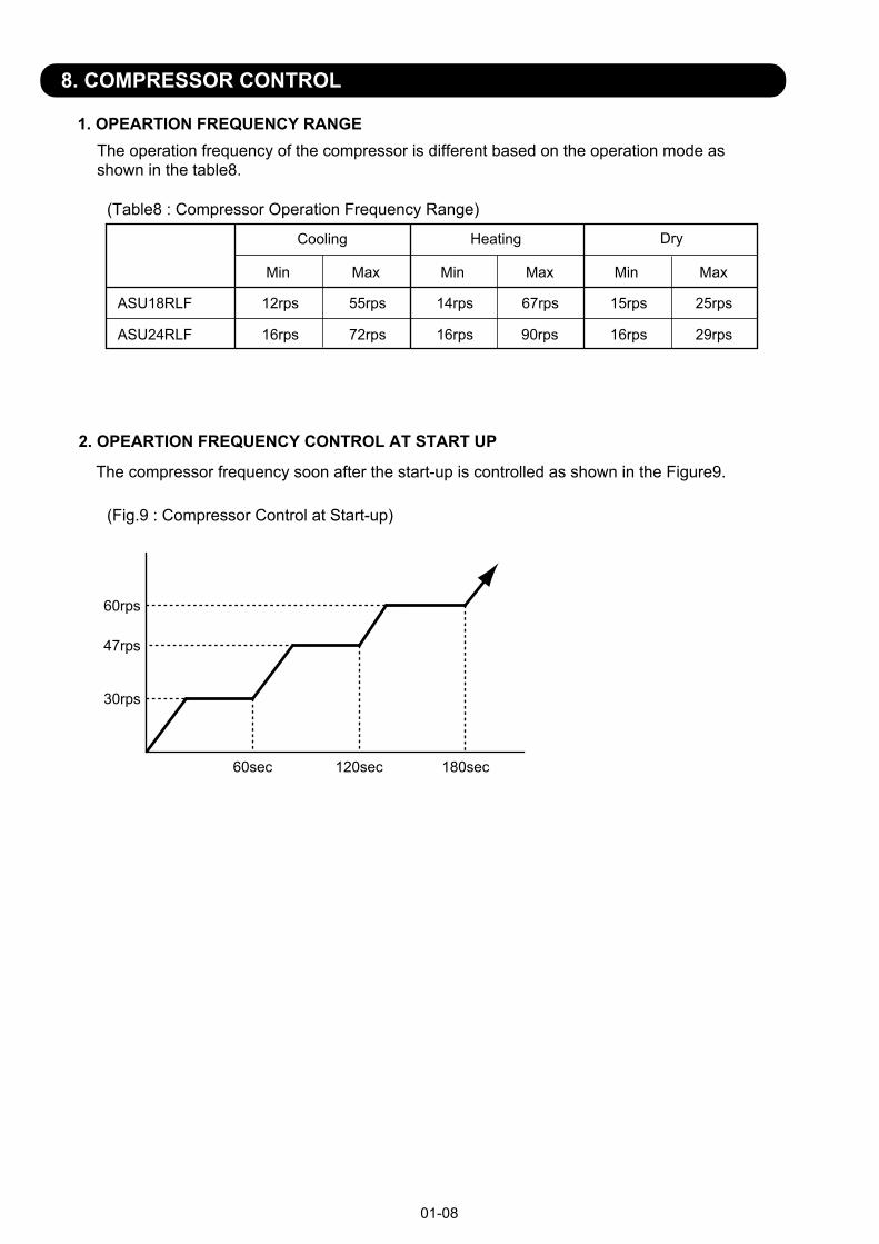
2. OPEARTION FREQUENCY CONTROL AT START UP
The compressor frequency soon after the start-up is controlled as shown in the Figure9.
(Fig.9 : Compressor Control at Start-up)
01-08
30rps
60sec
47rps
60rps
120sec 180sec
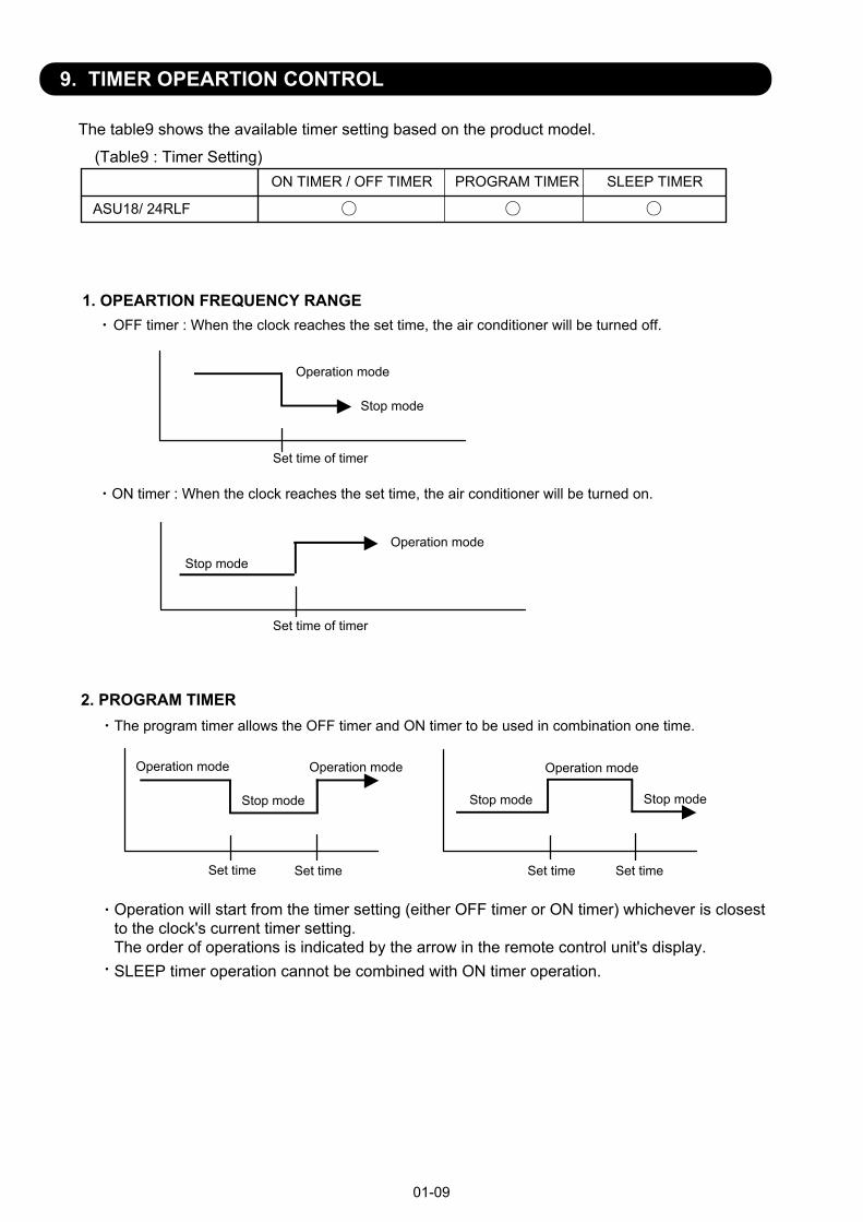
9. TIMER OPEARTION CONTROL
1. OPEARTION FREQUENCY RANGE
The table9 shows the available timer setting based on the product model.
ON TIMER / OFF TIMER PROGRAM TIMER SLEEP TIMER
ASU18/ 24RLF
OFF timer : When the clock reaches the set time, the air conditioner will be turned off.
Operation mode
Stop mode
Set time of timer
ON timer : When the clock reaches the set time, the air conditioner will be turned on.
Operation modeStop mode
Set time of timer
The program timer allows the OFF timer and ON timer to be used in combination one time.
Operation mode
Operation will start from the timer setting (either OFF timer or ON timer) whichever is closestto the clock's current timer setting. The order of operations is indicated by the arrow in the remote control unit's display.SLEEP timer operation cannot be combined with ON timer operation.
(Table9 : Timer Setting)
2. PROGRAM TIMER
Stop mode Stop mode Stop mode
Operation mode Operation mode
Set time Set time Set time Set time
01-09
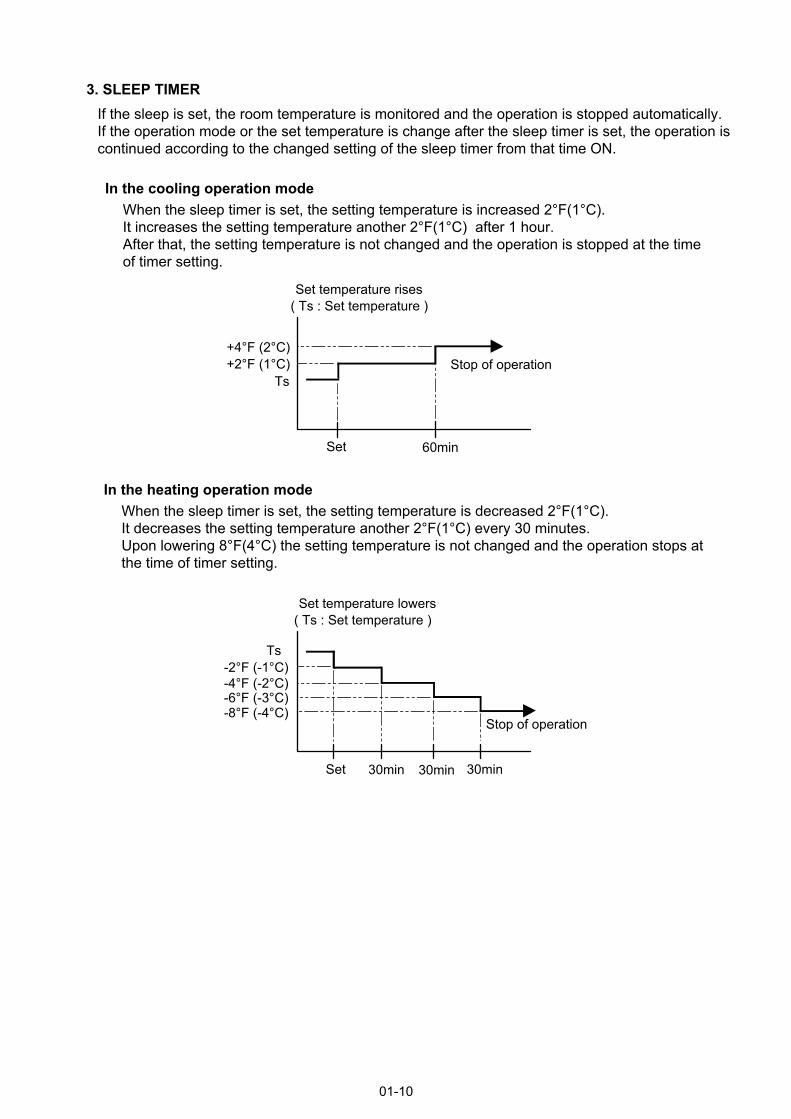
3. SLEEP TIMERIf the sleep is set, the room temperature is monitored and the operation is stopped automatically.If the operation mode or the set temperature is change after the sleep timer is set, the operation iscontinued according to the changed setting of the sleep timer from that time ON.
Set temperature rises( Ts : Set temperature )
Stop of operation
Set temperature lowers( Ts : Set temperature )
Ts
Stop of operation
In the cooling operation modeWhen the sleep timer is set, the setting temperature is increased 2°F(1°C).It increases the setting temperature another 2°F(1°C) after 1 hour.After that, the setting temperature is not changed and the operation is stopped at the timeof timer setting.
Ts+2°F (1°C)+4°F (2°C)
Set 60min
In the heating operation modeWhen the sleep timer is set, the setting temperature is decreased 2°F(1°C).It decreases the setting temperature another 2°F(1°C) every 30 minutes.Upon lowering 8°F(4°C) the setting temperature is not changed and the operation stops atthe time of timer setting.
-8°F (-4°C)-6°F (-3°C)-4°F (-2°C)-2°F (-1°C)
Set 30min 30min 30min
01-10
10. ELECTRONIC EXPANSION VALVE CONTROLThe most proper opening of the electronic expansion valve is calculated and controlled under thepresent operating condition based on the Table12.The compressor frequency, the temperatures detected by the discharge temperature sensor, theindoor heat exchanger sensor, the outdoor heat exchanger sensor, and the outdoor temperature sensor.
The expansion valve is set at 480 pulses after 120 seconds of stopping compressor.At the time of supplying the power to the outdoor unit, the initialization of the electronicexpansion valve is operated (528 pulses are input to the closing direction).
11. TEST OPERATION CONTROLUnder the condition where the air conditioner runs, press the test run button of the remotecontrol, and the test operation control mode will appear. During test running, the operation lampand timer lamp of the air conditioner body twinkle simultaneously. Set the test operation mode,and the compressor will continue to run regardless of whether the room temperature sensor detects.The test operation mode is released if 60 minutes have passed after setting up the test operation.
The compressor won't enter operation status for 3 minutes after the compressor is stopped, even if any operation is given.
At the time when the air conditioner is switched from the cooling mode to heating mode, thecompressor is stopped, and the four-way valve is switched in 3 minutes later after the compressorstopped.
When the power was interrupted by a power failure, etc. during operation, the operation contentsat that time are memorized and when power is recovered, operation is automatically started withthe memorized operation contents.When the power is interrupted and recovered during timer operation, since the timer operation timeis shifted by the time the power was interrupted, an alarm is given by blinking (7 sec ON/2 sec OFF)the indoor unit body timer lamp.
[Operation contents memorized when the power is interrupted]Operation modeSet temperatureSet air flowTimer mode and timer timeSet air flow DirectionSwingECONOMY operationMINIMUM HEAT operation
12. PREVENT TO RESTART FOR 3 MINUTES ( 3 MINUTES ST )
13. FOUR-WAY VALVE EXTENSION SELECT
14. AUTO RESTART
01-11
Cooling / Dry modeHeating modeCooling / Dry modeHeating mode
ASU18RLF
ASU24RLF
Operation mode Pulse rangebetween 52 to 480 pulses.between 40 to 480 pulses.between 53 to 480 pulses.between 40 to 480 pulses.
Table10 : The pulse range of the electronic expansion valve control
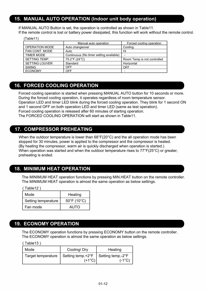
15. MANUAL AUTO OPERATION (Indoor unit body operation)
If MANUAL AUTO Button is set, the operation is controlled as shown in Table11.If the remote control is lost or battery power dissipated, this function will work without the remote control.
OPERATION MODE Auto changeoverFAN CONT. MODE AutoTIMER MODE Continuous SETTING TEMP. 75.2°F (24°C)SETTING LOUVER StandardSWINGECONOMY
OFFOFF
When the outdoor temperature is lower than 68°F(20°C) and the all operation mode has been stopped for 30 minutes, power is applied to the compressor and the compressor is heated.(By heating the compressor, warm air is quickly discharged when operation is started.)When operation was started and when the outdoor temperature rises to 77°F(25°C) or greater, preheating is ended.
(Table11)
(No timer setting available)
17. COMPRESSOR PREHEATING
01-12
Forced cooling operationCooling
16. FORCED COOLING OPERATIONForced cooling operation is started when pressing MANUAL AUTO button for 10 seconds or more.During the forced cooling operation, it operates regardless of room temperature sensor.Operation LED and timer LED blink during the forced cooling operation. They blink for 1 second ONand 1 second OFF on both operation LED and timer LED (same as test operation).Forced cooling operation is released after 60 minutes of starting operation.The FORCED COOLING OPERATION will start as shown in Table11.
Hi
HorizontalOFF
Room Temp is not controlled
Manual auto operation
-
-
18. MINIMUM HEAT OPERATIONThe MINIMUM HEAT operation functions by pressing MIN.HEAT button on the remote controller.The MINIMUM HEAT operation is almost the same operation as below settings.
Mode HeatingSetting temperature 50°F (10°C)Fan mode AUTO
( Table12 )
19. ECONOMY OPERATIONThe ECONOMY operation functions by pressing ECONOMY button on the remote controller.The ECONOMY operation is almost the same operation as below settings.
Mode Cooling/ Dry HeatingTarget temperature Setting temp.+2°F Setting temp.-2°F (+1°C) (-1°C)
( Table13 )
20. DEFROST OPERATION CONTROL
01-13
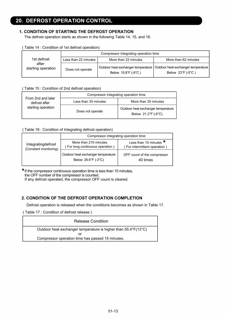
1. CONDITION OF STARTING THE DEFROST OPERATION
Integratingdefrost (Constant monitoring)
If the compressor continuous operation time is less than 10 minutes, the OFF number of the compressor is counted.If any defrost operated, the compressor OFF count is cleared.
2. CONDITION OF THE DEFROST OPERATION COMPLETIONDefrost operation is released when the conditions becomes as shown in Table 17.
( Table 17 : Condition of defrost release )
Release Condition
Outdoor heat exchanger temperature is higher than 55.4°F(13°C) orCompressor operation time has passed 15 minutes.
The defrost operation starts as shown in the following Table 14, 15, and 16.
From 2nd and later defrost after
starting operationLess than 35 minutes More than 35 minutes
Does not operate
Compressor integrating operation time
( Table 14 : Condition of 1st defrost operation)
1st defrost after
starting operation
Compressor integrating operation time
Less than 22 minutes More than 22 minutes More than 62 minutes
Does not operate Outdoor heat exchanger temperatureBelow 15.8°F (-9°C )
Outdoor heat exchanger temperatureBelow 21.2°F (-6°C)
Outdoor heat exchanger temperatureBelow 23°F (-5°C )
More than 210 minutes( For long continuous operation )
Less than 10 minutes( For intermittent operation )
Compressor integrating operation time
Outdoor heat exchanger temperatureBelow 26.6°F (-3°C)
OFF count of the compressor40 times
( Table 16 : Condition of Integrating defrost operation)
( Table 15 : Condition of 2nd defrost operation)
01-14
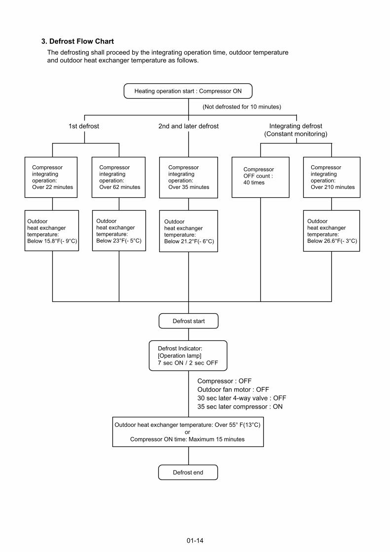
3. Defrost Flow ChartThe defrosting shall proceed by the integrating operation time, outdoor temperature and outdoor heat exchanger temperature as follows.
(Not defrosted for 10 minutes)
Heating operation start : Compressor ON
Outdoor heat exchanger temperature: Over 55° F(13°C)or
Compressor ON time: Maximum 15 minutes
Defrost end
Compressorintegrating operation:Over 22 minutes
Compressor integrating operation:Over 62 minutes
Outdoor heat exchangertemperature:Below 15.8°F(- 9°C)
Outdoor heat exchangertemperature:Below 23°F(- 5°C)
Compressor integrating operation:Over 35 minutes
2nd and later defrost
Compressor : OFFOutdoor fan motor : OFF30 sec later 4-way valve : OFF35 sec later compressor : ON
Compressor integrating operation:Over 210 minutes
Integrating defrost(Constant monitoring)
Defrost Indicator:[Operation lamp]7 sec ON / 2 sec OFF
Defrost start
Outdoor heat exchangertemperature:Below 21.2°F(- 6°C)
Outdoor heat exchangertemperature:Below 26.6°F(- 3°C)
Compressor OFF count :40 times
1st defrost
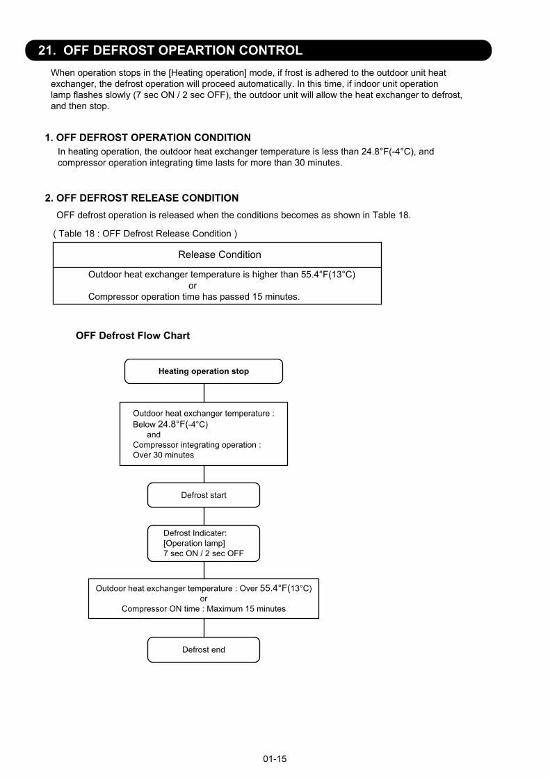
21. OFF DEFROST OPEARTION CONTROL
01-15
1. OFF DEFROST OPERATION CONDITION
When operation stops in the [Heating operation] mode, if frost is adhered to the outdoor unit heatexchanger, the defrost operation will proceed automatically. In this time, if indoor unit operation lamp flashes slowly (7 sec ON / 2 sec OFF), the outdoor unit will allow the heat exchanger to defrost, and then stop.
In heating operation, the outdoor heat exchanger temperature is less than 24.8°F(-4°C), andcompressor operation integrating time lasts for more than 30 minutes.
OFF Defrost Flow Chart
Heating operation stop
Outdoor heat exchanger temperature :Below 24.8°F(-4°C) andCompressor integrating operation :Over 30 minutes
Defrost start
Defrost Indicater:[Operation lamp]7 sec ON / 2 sec OFF
Outdoor heat exchanger temperature : Over 55.4°F(13°C) or
Compressor ON time : Maximum 15 minutes
Defrost end
2. OFF DEFROST RELEASE CONDITION
Release Condition
Outdoor heat exchanger temperature is higher than 55.4°F(13°C) orCompressor operation time has passed 15 minutes.
( Table 18 : OFF Defrost Release Condition )
OFF defrost operation is released when the conditions becomes as shown in Table 18.
22. VARIOUS PROTECTIONS
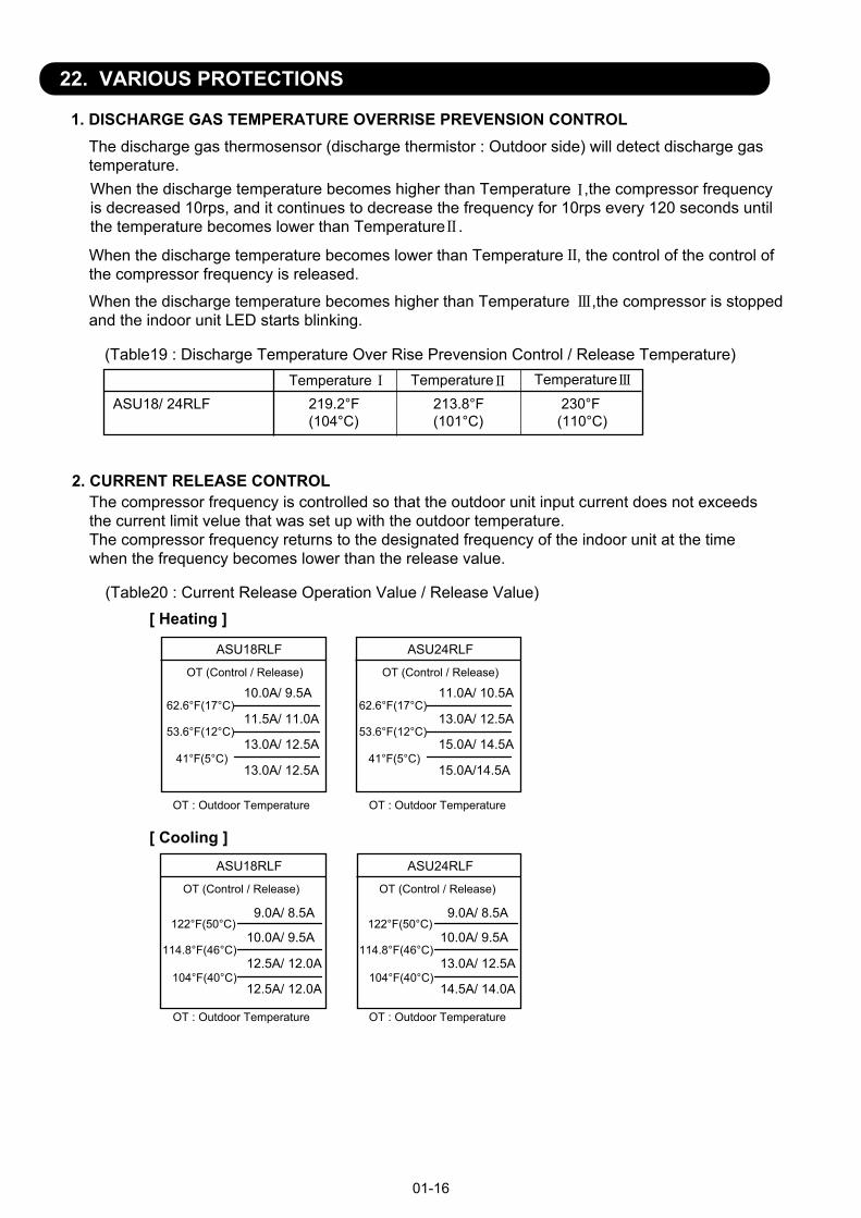
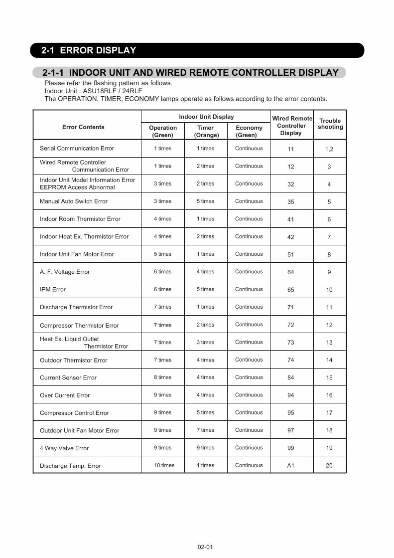
1. DISCHARGE GAS TEMPERATURE OVERRISE PREVENSION CONTROLThe discharge gas thermosensor (discharge thermistor : Outdoor side) will detect discharge gastemperature.
ASU18/ 24RLF 219.2°F(104°C)
213.8°F(101°C)
230°F(110°C)
When the discharge temperature becomes higher than Temperature ,the compressor frequencyis decreased 10rps, and it continues to decrease the frequency for 10rps every 120 seconds untilthe temperature becomes lower than Temperature .
When the discharge temperature becomes lower than Temperature , the control of the control of the compressor frequency is released.
When the discharge temperature becomes higher than Temperature ,the compressor is stoppedand the indoor unit LED starts blinking.
(Table19 : Discharge Temperature Over Rise Prevension Control / Release Temperature)Temperature Temperature Temperature
2. CURRENT RELEASE CONTROLThe compressor frequency is controlled so that the outdoor unit input current does not exceedsthe current limit velue that was set up with the outdoor temperature.The compressor frequency returns to the designated frequency of the indoor unit at the timewhen the frequency becomes lower than the release value.
(Table20 : Current Release Operation Value / Release Value)
01-16
[ Heating ]
OT (Control / Release)
10.0A/ 9.5A
11.5A/ 11.0A
13.0A/ 12.5A
13.0A/ 12.5A
11.0A/ 10.5A
13.0A/ 12.5A
15.0A/ 14.5A
15.0A/14.5A
62.6°F(17°C)
53.6°F(12°C)
OT : Outdoor Temperature
41°F(5°C)
62.6°F(17°C)
53.6°F(12°C)
41°F(5°C)
ASU18RLF
OT (Control / Release)
OT : Outdoor Temperature
ASU24RLF
OT (Control / Release)
10.0A/ 9.5A
12.5A/ 12.0A
12.5A/ 12.0A
10.0A/ 9.5A
13.0A/ 12.5A
14.5A/ 14.0A
114.8°F(46°C)
104°F(40°C)
114.8°F(46°C)
104°F(40°C)
OT : Outdoor Temperature
ASU18RLF
OT (Control / Release)
OT : Outdoor Temperature
ASU24RLF
[ Cooling ]
122°F(50°C) 122°F(50°C)9.0A/ 8.5A 9.0A/ 8.5A
3. ANTIFREEZING CONTROL (Cooling and Dry mode)The compressor frequency is decrease on cooling & dry mode when the indoor heat exchangertemperature sensor detects the temperature lower than Temperature .Then, the anti-freezing control is released when it becomes higher than Temperature .
(Table21 : Anti-freezing Protection Operation / Release Temperature)
4. COOLING PRESSURE OVERRISE PROTECTIONWhen the outdoor unit heat exchange sensor temperature rises to 152.6°F (67°C) or greater, the compressor and the outdoor fan motor are stopped and trouble display is performed.
5. HIGH TEMPERATURE RELEASE CONTROL ( HEATING MODE )On heating mode, the compressor frequency is controlled as following based on thedetection value of the indoor heat exchanger temperature sensor.
01-17
Indoor heat exchange temperature
[ Control System ]
It returns to the normal operation
145.4°F (63°C)
Outdoor temperatureOver than 50°F(10°C) *1 or 53.6°F(12°C) *2Less than 50°F(10°C) *1 or 53.6°F(12°C) *2
*1. When the temperature rises.*2. When the temperature drops.
39.2°F (4°C)44.6°F (7°C)
55.4°F (13°C)
Temperature Temperature
compressor stop
131°F (55°C)
127.4°F (53°C)
The compressor frequency is decreased 15rps every 120seconds.
The compressor frequency is decreased 2rps every 120seconds. The compressor frequency is
Maintenance of status quo.
122°F (50°C)
2 . TROUBLE SHOOTING
R410A
WALL MOUNTED typeINVERTER
Manual Auto Switch Error
Indoor Room Thermistor Error
Indoor Unit Model Information ErrorEEPROM Access Abnormal
Wired Remote Controller Communication Error
Error Contents
Continuous
Continuous
4 times
Continuous2 times
3 times
3 times
5 times
Continuous2 times1 times
Continuous1 times1 times
TroubleshootingEconomy
(Green) Timer(Orange)
Operation (Green)
02-01
2-1 ERROR DISPLAY
2-1-1 INDOOR UNIT AND WIRED REMOTE CONTROLLER DISPLAY
1 times
Serial Communication Error
Indoor Unit Fan Motor Error
Indoor Heat Ex. Thermistor Error
Continuous4 times 2 times
Continuous1 times5 times
Continuous
Continuous4 times
7 times
6 times
1 times
Continuous
7 times 3 times Continuous
7 times 4 times Continuous
2 times7 times
A. F. Voltage Error
Discharge Thermistor Error
Heat Ex. Liquid Outlet Thermistor Error
Outdoor Thermistor Error
Compressor Thermistor Error
Please refer the flashing pattern as follows.Indoor Unit : ASU18RLF / 24RLFThe OPERATION, TIMER, ECONOMY lamps operate as follows according to the error contents.
1,2
3
4
5
6
7
8
9
10
11
12
13
14
15
16
17
18
19
20
Continuous8 times 4 timesCurrent Sensor Error
Continuous
Continuous5 times
9 times
9 times
7 times
Compressor Control Error
Outdoor Unit Fan Motor Error
Continuous4 times9 times
Continuous9 times 9 times4 Way Valve Error
Continuous1 times10 timesDischarge Temp. Error
Over Current Error
Continuous5 times6 timesIPM Error
Indoor Unit Display Wired Remote Controller Display
11
12
32
35
41
42
51
64
65
71
72
73
74
84
94
95
97
99
A1
02-02
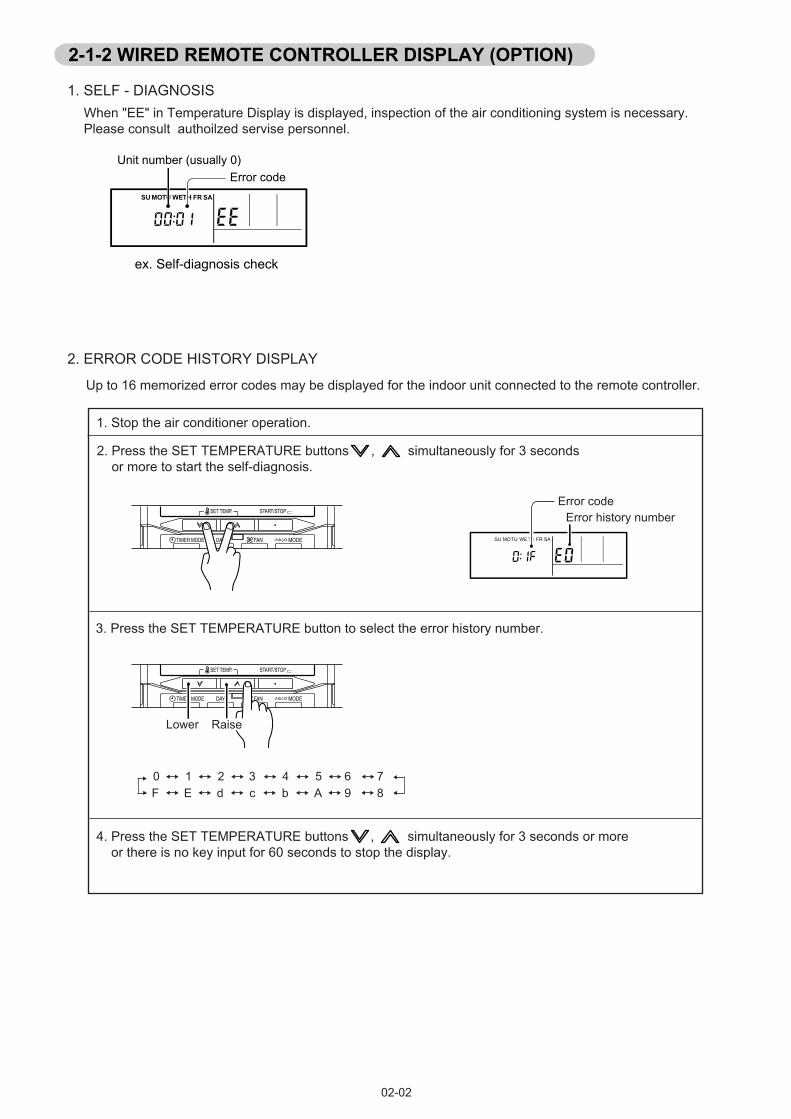
When "EE" in Temperature Display is displayed, inspection of the air conditioning system is necessary. Please consult authoilzed servise personnel.
2-1-2 WIRED REMOTE CONTROLLER DISPLAY (OPTION)
1. SELF - DIAGNOSIS
SU MOTU WETH FR SA
Unit number (usually 0)Error code
ex. Self-diagnosis check
2. ERROR CODE HISTORY DISPLAY
Up to 16 memorized error codes may be displayed for the indoor unit connected to the remote controller.
1. Stop the air conditioner operation.
2. Press the SET TEMPERATURE buttons , simultaneously for 3 seconds or more to start the self-diagnosis.
4. Press the SET TEMPERATURE buttons , simultaneously for 3 seconds or more or there is no key input for 60 seconds to stop the display.
3. Press the SET TEMPERATURE button to select the error history number.
SU MOTU WETH FR SA
Error codeError history number
0 1 2 3 4 5 6 7F E d c b A 9 8
��
Lower Raise
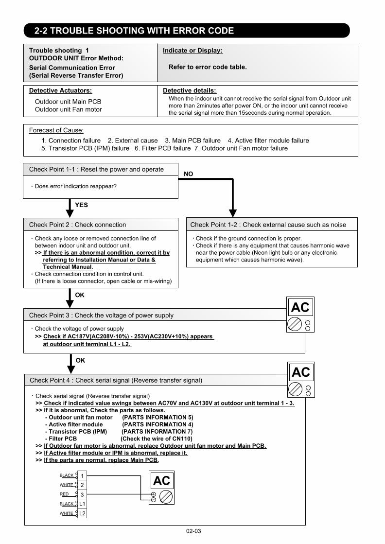
Trouble shooting 1 OUTDOOR UNIT Error Method:
Detective Actuators: Detective details:
Forecast of Cause:
OK
Indicate or Display:
Refer to error code table.
YESYES
NO
Serial Communication Error (Serial Reverse Transfer Error)
Outdoor unit Main PCBOutdoor unit Fan motor
1. Connection failure 2. External cause 3. Main PCB failure 4. Active filter module failure5. Transistor PCB (IPM) failure 6. Filter PCB failure 7. Outdoor unit Fan motor failure
Check Point 1-1 : Reset the power and operate
Does error indication reappear?
Check Point 1-2 : Check external cause such as noise
Check if the ground connection is proper.Check if there is any equipment that causes harmonic wave near the power cable (Neon light bulb or any electronic equipment which causes harmonic wave).
Check Point 2 : Check connection
Check any loose or removed connection line of between indoor unit and outdoor unit. >> If there is an abnormal condition, correct it by referring to Installation Manual or Data & Technical Manual. Check connection condition in control unit.(If there is loose connector, open cable or mis-wiring)
Check Point 3 : Check the voltage of power supply
Check the voltage of power supply >> Check if AC187V(AC208V-10%) - 253V(AC230V+10%) appears at outdoor unit terminal L1 - L2.
When the indoor unit cannot receive the serial signal from Outdoor unit more than 2minutes after power ON, or the indoor unit cannot receivethe serial signal more than 15seconds during normal operation.
02-03
2-2 TROUBLE SHOOTING WITH ERROR CODE
OK
Check Point 4 : Check serial signal (Reverse transfer signal)
Check serial signal (Reverse transfer signal) >> Check if indicated value swings between AC70V and AC130V at outdoor unit terminal 1 - 3. >> If it is abnormal, Check the parts as follows. - Outdoor unit fan motor (PARTS INFORMATION 5) - Active filter module (PARTS INFORMATION 4) - Transistor PCB (IPM) (PARTS INFORMATION 7) - Filter PCB (Check the wire of CN110)>> If Outdoor fan motor is abnormal, replace Outdoor unit fan motor and Main PCB.>> If Active filter module or IPM is abnormal, replace it.>> If the parts are normal, replace Main PCB.
12
3 L1
L2
RED
WHITE
BLACK
BLACK
WHITE
+-
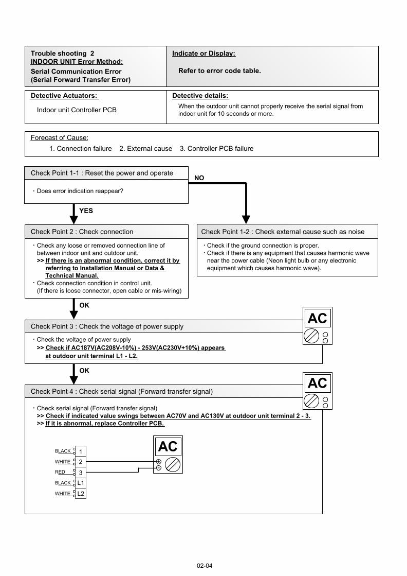
Trouble shooting 2 INDOOR UNIT Error Method:
Detective Actuators: Detective details:
Forecast of Cause:
OK
Indicate or Display:
Refer to error code table.
YESYES
NO
OK
Serial Communication Error(Serial Forward Transfer Error)
Indoor unit Controller PCB
1. Connection failure 2. External cause 3. Controller PCB failure
Check Point 1-1 : Reset the power and operate
Does error indication reappear?
Check Point 1-2 : Check external cause such as noise
Check if the ground connection is proper.Check if there is any equipment that causes harmonic wave near the power cable (Neon light bulb or any electronic equipment which causes harmonic wave).
Check Point 2 : Check connection
Check any loose or removed connection line of between indoor unit and outdoor unit. >> If there is an abnormal condition, correct it by referring to Installation Manual or Data & Technical Manual. Check connection condition in control unit.(If there is loose connector, open cable or mis-wiring)
Check Point 3 : Check the voltage of power supply
Check the voltage of power supply >> Check if AC187V(AC208V-10%) - 253V(AC230V+10%) appears at outdoor unit terminal L1 - L2.
Check Point 4 : Check serial signal (Forward transfer signal)
Check serial signal (Forward transfer signal) >> Check if indicated value swings between AC70V and AC130V at outdoor unit terminal 2 - 3. >> If it is abnormal, replace Controller PCB.
When the outdoor unit cannot properly receive the serial signal fromindoor unit for 10 seconds or more.
02-04
12
3 L1
L2
RED
WHITE
BLACK
BLACK
WHITE
+-
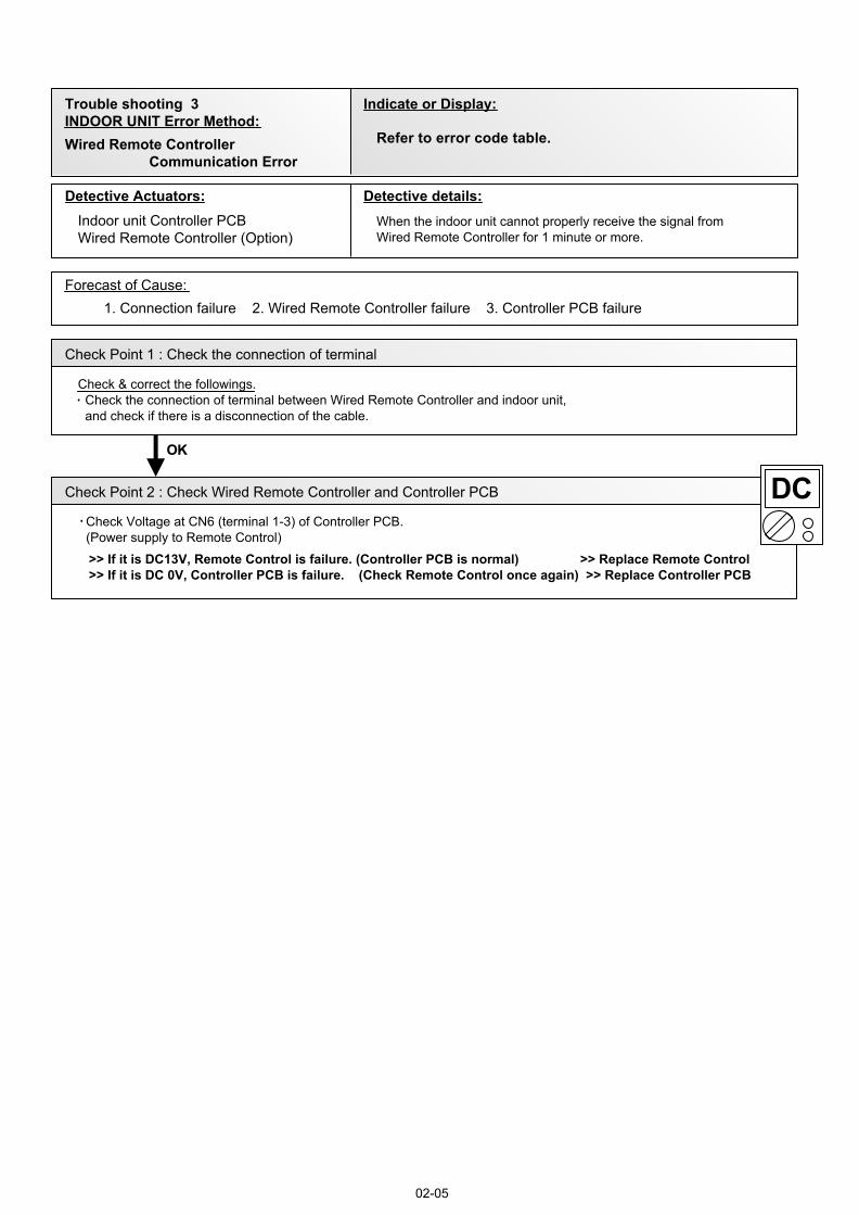
Trouble shooting 3INDOOR UNIT Error Method:
Detective Actuators: Detective details:
Forecast of Cause:
Check Point 2 : Check Wired Remote Controller and Controller PCB
Check Point 1 : Check the connection of terminal
OKOK
Indicate or Display:
Wired Remote Controller Communication Error
Indoor unit Controller PCBWired Remote Controller (Option)
1. Connection failure 2. Wired Remote Controller failure 3. Controller PCB failure
Check & correct the followings. Check the connection of terminal between Wired Remote Controller and indoor unit, and check if there is a disconnection of the cable.
When the indoor unit cannot properly receive the signal fromWired Remote Controller for 1 minute or more.
02-05
Refer to error code table.
>> If it is DC13V, Remote Control is failure. (Controller PCB is normal) >> Replace Remote Control>> If it is DC 0V, Controller PCB is failure. (Check Remote Control once again) >> Replace Controller PCB
Check Voltage at CN6 (terminal 1-3) of Controller PCB.(Power supply to Remote Control)
02-06
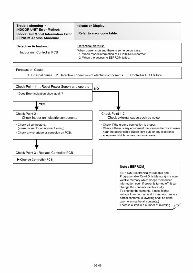
Trouble shooting 4INDOOR UNIT Error Method:
Indicate or Display:
Indoor Unit Model Information ErrorEEPROM Access Abnormal
Refer to error code table.
Detective Actuators: Detective details:
Forecast of Cause:
Check Point 3 : Replace Controller PCB
Check Point 2 : Check Indoor unit electric components
YESYES
NO
Indoor unit Controller PCB
1. External cause 2. Defective connection of electric components 3. Controller PCB failure
Check Point 1-1 : Reset Power Supply and operate
Does Error indication show again?
Check Point 1-2 : Check external cause such as noise
Check if the ground connection is proper.Check if there is any equipment that causes harmonic wavenear the power cable (Neon light bulb or any electronicequipment which causes harmonic wave).
Note : EEPROM
EEPROM(Electronically Erasable andProgrammable Read Only Memory) is a non-volatile memory which keeps memorizedinformation even if power is turned off. It canchange the contents electronically. To change the contents, it uses higher voltage than normal, and it can not change a partial contents. (Rewriting shall be done upon erasing the all contents.) There is a limit in a number of rewriting.
Change Controller PCB.
Check all connectors.(loose connector or incorrect wiring)Check any shortage or corrosion on PCB.
When power is on and there is some below case. 1. When model information of EEPROM is incorrect. 2. When the access to EEPROM failed.
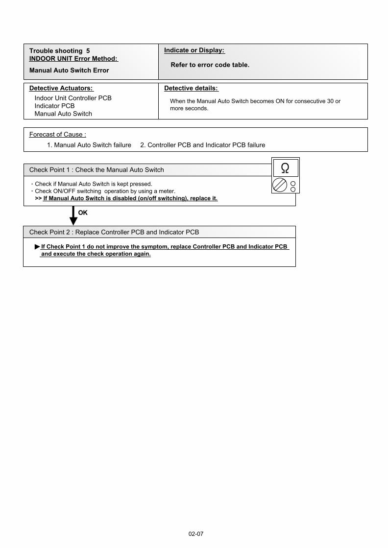
Trouble shooting 5 INDOOR UNIT Error Method:
Indicate or Display:
Detective Actuators: Detective details:
Forecast of Cause :
OKOK
Manual Auto Switch Error
Indoor Unit Controller PCBIndicator PCBManual Auto Switch
When the Manual Auto Switch becomes ON for consecutive 30 ormore seconds.
1. Manual Auto Switch failure 2. Controller PCB and Indicator PCB failure
Check Point 1 : Check the Manual Auto Switch
Check if Manual Auto Switch is kept pressed.Check ON/OFF switching operation by using a meter. >> If Manual Auto Switch is disabled (on/off switching), replace it.
Check Point 2 : Replace Controller PCB and Indicator PCB
If Check Point 1 do not improve the symptom, replace Controller PCB and Indicator PCB and execute the check operation again.
02-07
Refer to error code table.
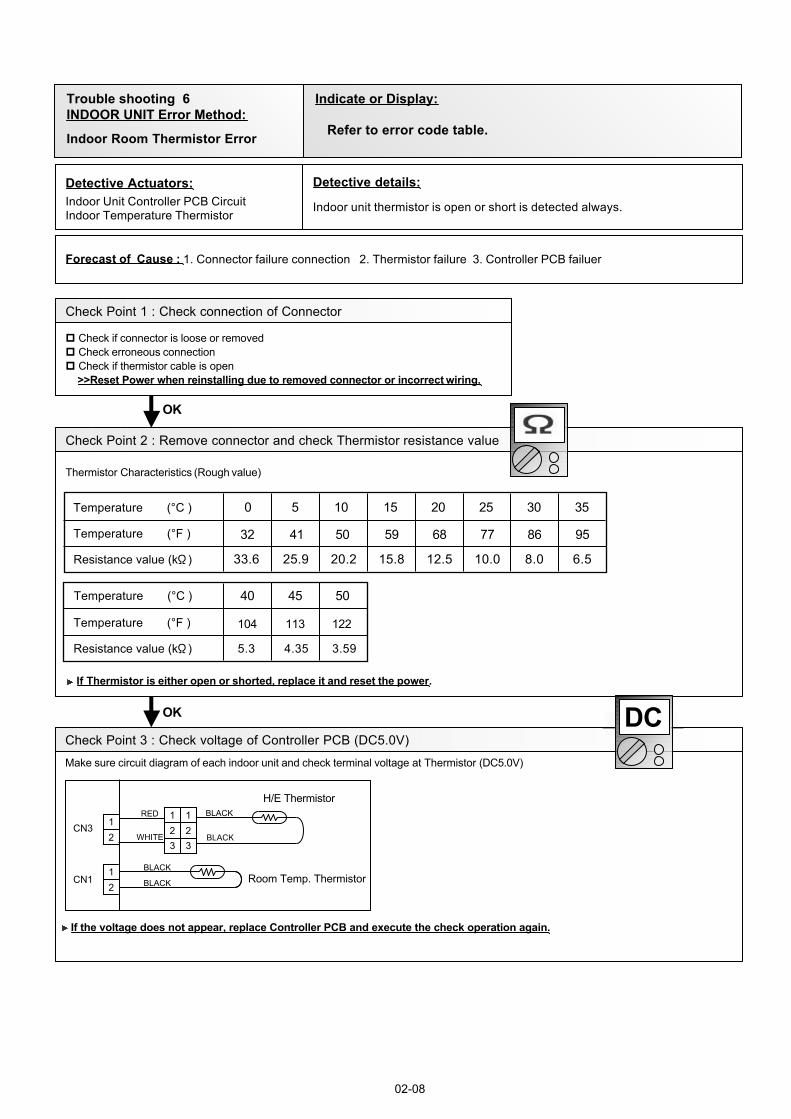
Detective Actuators:Indoor Unit Controller PCB CircuitIndoor Temperature Thermistor
Detective details:
Indoor unit thermistor is open or short is detected always.
Forecast of Cause : 1. Connector failure connection 2. Thermistor failure 3. Controller PCB failuer
Check Point 2 : Remove connector and check Thermistor resistance value
Thermistor Characteristics (Rough value)
If Thermistor is either open or shorted, replace it and reset the power.
Check Point 1 : Check connection of Connector
Check if connector is loose or removedCheck erroneous connectionCheck if thermistor cable is open>>Reset Power when reinstalling due to removed connector or incorrect wiring.
6.5
95
8.0
86
10.012.515.820.225.933.6
776859504132Temperature (°F )
3.594.355.3Resistance value (k )
122113104Temperature (°F )
OK
OK
Check Point 3 : Check voltage of Controller PCB (DC5.0V)
Make sure circuit diagram of each indoor unit and check terminal voltage at Thermistor (DC5.0V)
If the voltage does not appear, replace Controller PCB and execute the check operation again.
DC
BLACK
BLACK
BLACK
BLACK
12
12
CN3
CN1
123
123
RED
WHITE
H/E Thermistor
Room Temp. Thermistor
02-08
Trouble shooting 6INDOOR UNIT Error Method:
Indicate or Display:
Indoor Room Thermistor Error Refer to error code table.
Temperature (°C )
Temperature (°C ) 0
40 45 50
5 10 15 20 25 30 35
Resistance value (k )
Thermistor Characteristics (Rough value)
If Thermistor is either open or shorted, replace it and reset the power.
Detective Actuators:Indoor Unit Controller PCBHeat Exchanger (MID) Thermistor
Detective details:Indoor unit thermistor is open or short is detected always.
Forecast of Cause : 1. Connector failure connection 2. Thermistor failure 3. Controller PCB failuer
Check Point 1 : Check connection of Connector
Check if connector is loose or removedCheck erroneous connectionCheck if thermistor cable is open>>Reset Power when reinstalling due to removed connector or incorrect wiring.
OK
Check Point 2 : Remove connector and check Thermistor resistance value
OK
Check Point 3 : Check voltage of Controller PCB (DC5.0V)
Make sure circuit diagram of each indoor unit and check terminal voltage at Thermistor (DC5.0V)
If the voltage does not appear, replace Controller PCB and execute the check operation again.
DC
BLACK
BLACK
BLACK
BLACK
12
12
CN3
CN1
123
123
RED
WHITE
H/E Thermistor
Room Temp. Thermistor
02-09
Trouble shooting 7INDOOR UNIT Error Method:
Indicate or Display:
Indoor Heat Ex. Thermistor Error Refer to error code table.
31.7
95
39.6
86
49.762.980.3103134176
776859504132Temperature (°F )
17.120.825.6Resistance value (k )
122113104Temperature (°F )
Temperature (°C )
Temperature (°C ) 0
40 45 50
5 10 15 20 25 30 35
Resistance value (k )
02-10
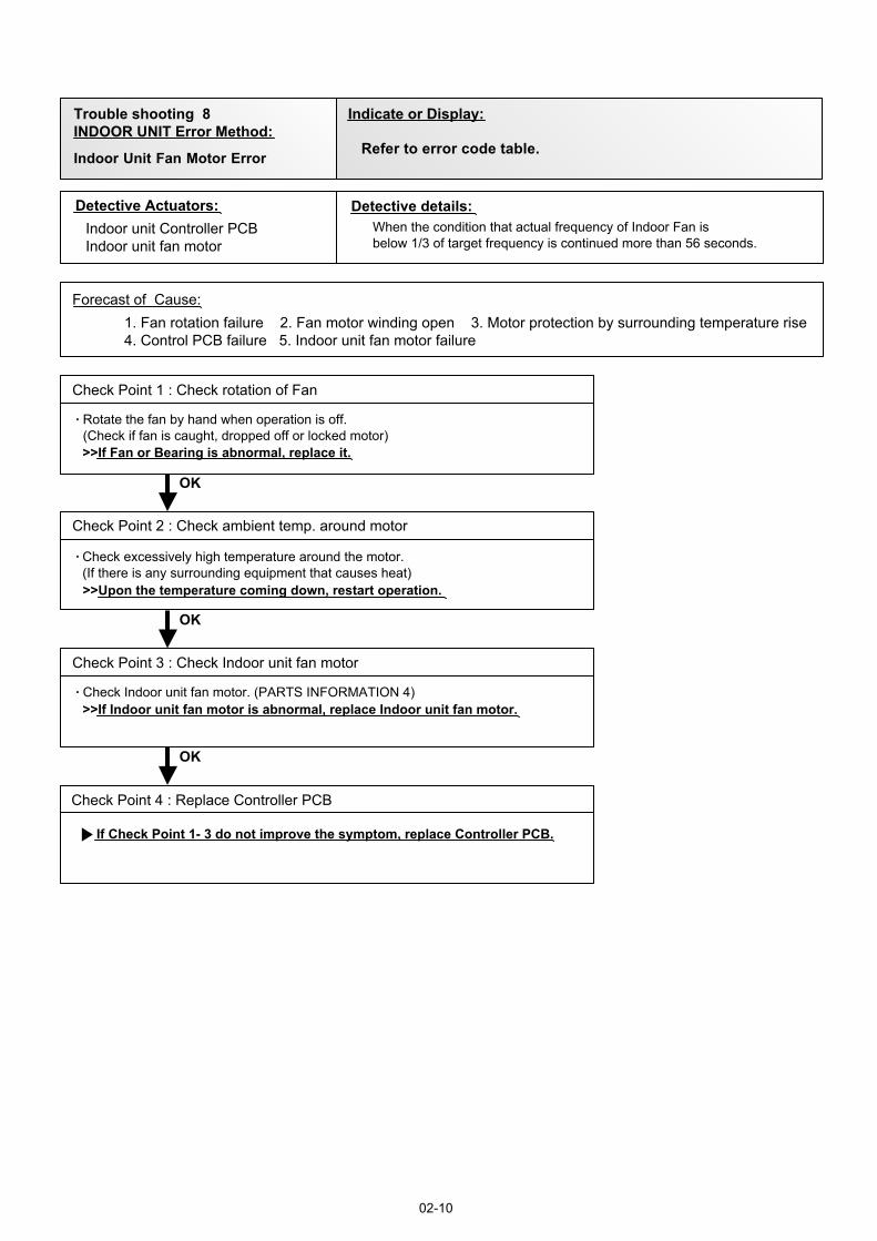
Trouble shooting 8INDOOR UNIT Error Method:
Indicate or Display:
Indoor Unit Fan Motor Error Refer to error code table.
Detective Actuators: Detective details:
Forecast of Cause:
Check Point 1 : Check rotation of Fan
Check Point 2 : Check ambient temp. around motor
OK
OK
OK
Indoor unit Controller PCBIndoor unit fan motor
1. Fan rotation failure 2. Fan motor winding open 3. Motor protection by surrounding temperature rise4. Control PCB failure 5. Indoor unit fan motor failure
Rotate the fan by hand when operation is off.(Check if fan is caught, dropped off or locked motor)>>If Fan or Bearing is abnormal, replace it.
Check excessively high temperature around the motor.(If there is any surrounding equipment that causes heat)>>Upon the temperature coming down, restart operation.
When the condition that actual frequency of Indoor Fan is below 1/3 of target frequency is continued more than 56 seconds.
Check Point 4 : Replace Controller PCB
If Check Point 1- 3 do not improve the symptom, replace Controller PCB.
Check Point 3 : Check Indoor unit fan motor
Check Indoor unit fan motor. (PARTS INFORMATION 4)>>If Indoor unit fan motor is abnormal, replace Indoor unit fan motor.
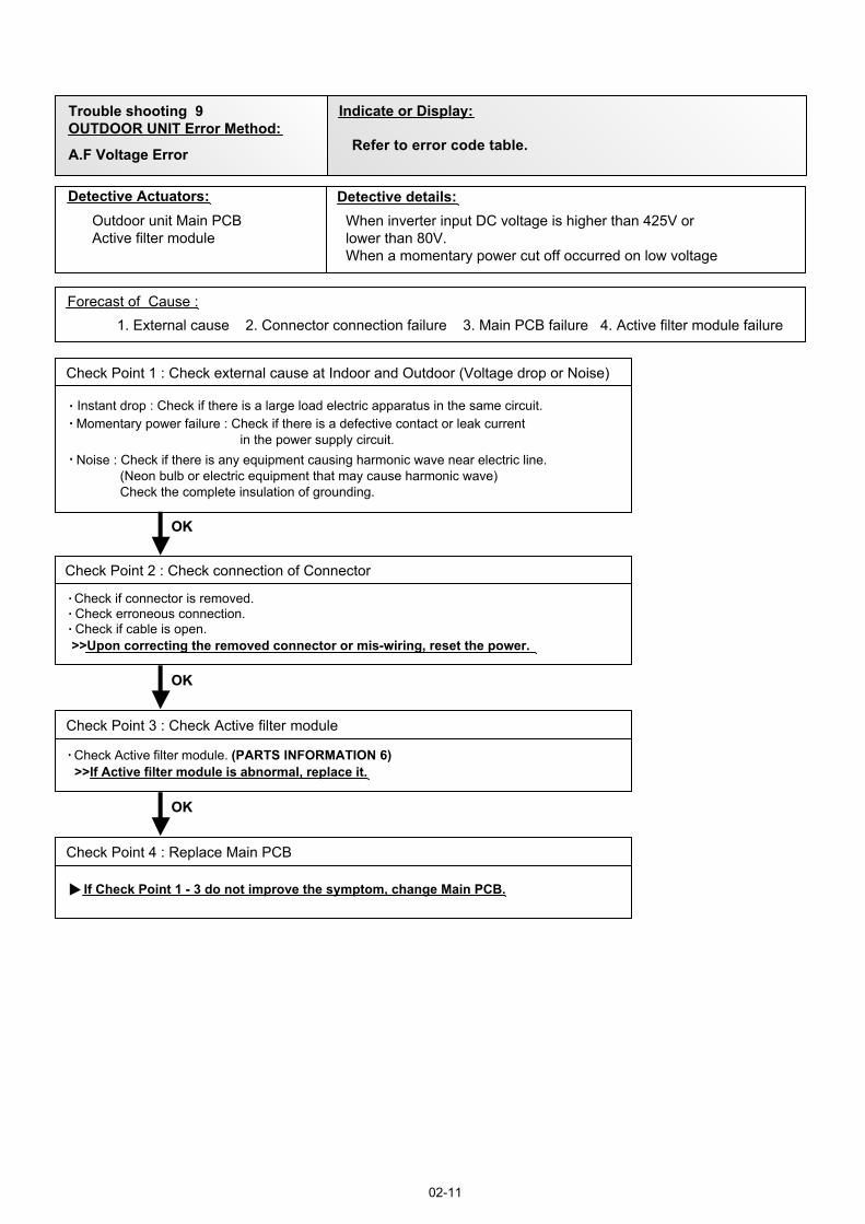
Trouble shooting 9OUTDOOR UNIT Error Method:
A.F Voltage Error
02-11
Indicate or Display:
Refer to error code table.
Detective Actuators: Detective details:
Forecast of Cause :
OKOK
OKOK
Outdoor unit Main PCBActive filter module
1. External cause 2. Connector connection failure 3. Main PCB failure 4. Active filter module failure
Check Point 2 : Check connection of Connector
Check if connector is removed.Check erroneous connection.Check if cable is open.>>Upon correcting the removed connector or mis-wiring, reset the power.
Check Point 4 : Replace Main PCB
If Check Point 1 - 3 do not improve the symptom, change Main PCB.
Check Point 1 : Check external cause at Indoor and Outdoor (Voltage drop or Noise)
Instant drop : Check if there is a large load electric apparatus in the same circuit.Momentary power failure : Check if there is a defective contact or leak current in the power supply circuit.Noise : Check if there is any equipment causing harmonic wave near electric line. (Neon bulb or electric equipment that may cause harmonic wave) Check the complete insulation of grounding.
OKOK
Check Point 3 : Check Active filter module
Check Active filter module. (PARTS INFORMATION 6)>>If Active filter module is abnormal, replace it.
When inverter input DC voltage is higher than 425V orlower than 80V.When a momentary power cut off occurred on low voltage
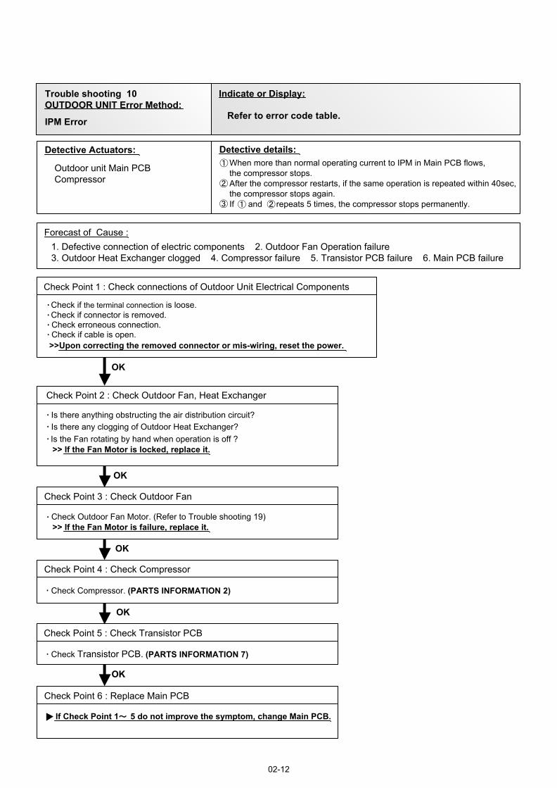
Detective Actuators: Detective details:
Forecast of Cause :
Check Point 3 : Check Outdoor Fan
OK
OK
Check Point 6 : Replace Main PCB
OKOK
Check Point 1 : Check connections of Outdoor Unit Electrical Components
Outdoor unit Main PCBCompressor
1. Defective connection of electric components 2. Outdoor Fan Operation failure 3. Outdoor Heat Exchanger clogged 4. Compressor failure 5. Transistor PCB failure 6. Main PCB failure
Check if connector is removed.Check if the terminal connection is loose.
Check erroneous connection.Check if cable is open.>>Upon correcting the removed connector or mis-wiring, reset the power.
Check Point 2 : Check Outdoor Fan, Heat Exchanger
Is there anything obstructing the air distribution circuit?Is there any clogging of Outdoor Heat Exchanger?Is the Fan rotating by hand when operation is off ?>> If the Fan Motor is locked, replace it.
Check Outdoor Fan Motor. (Refer to Trouble shooting 19) >> If the Fan Motor is failure, replace it.
Check Point 4 : Check Compressor
(PARTS INFORMATION 2)Check Compressor.
If Check Point 1 5 do not improve the symptom, change Main PCB.
When more than normal operating current to IPM in Main PCB flows,the compressor stops.After the compressor restarts, if the same operation is repeated within 40sec,the compressor stops again.If and repeats 5 times, the compressor stops permanently.
02-12
Trouble shooting 10OUTDOOR UNIT Error Method:
IPM Error
Indicate or Display:
Refer to error code table.
Check Point 5 : Check Transistor PCB
OK
OK
(PARTS INFORMATION 7)Check Transistor PCB.
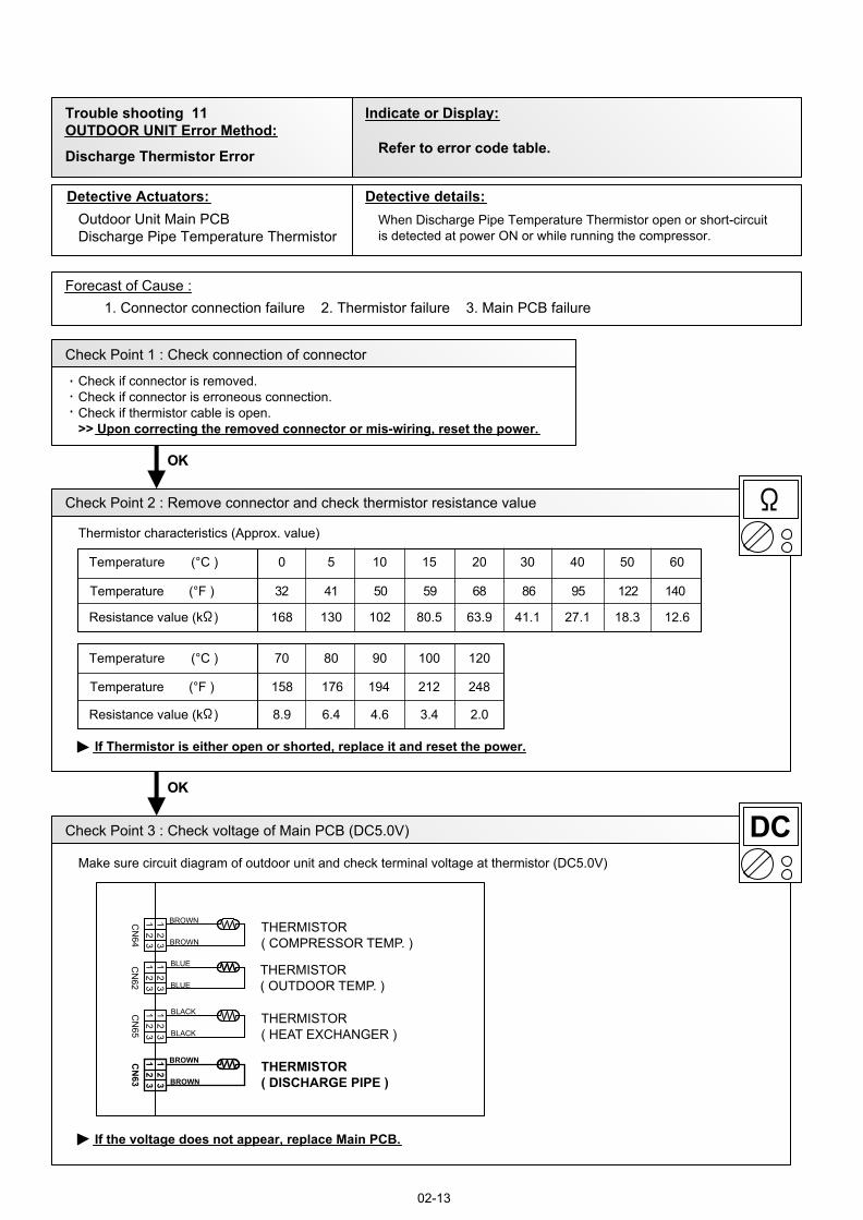
Trouble shooting 11 OUTDOOR UNIT Error Method:
Indicate or Display:
Detective Actuators: Detective details:
Forecast of Cause :
OKOK
OKOK
18.327.1
20
41.163.980.5102130168Resistance value (k )
151050Temperature (°C )
12.6
30 5040 60
2.03.44.66.48.9Resistance value (k )
120100908070Temperature (°C )
Discharge Thermistor Error
Outdoor Unit Main PCBDischarge Pipe Temperature Thermistor
When Discharge Pipe Temperature Thermistor open or short-circuit is detected at power ON or while running the compressor.
1. Connector connection failure 2. Thermistor failure 3. Main PCB failure
Check Point 1 : Check connection of connector
Check if connector is removed.Check if connector is erroneous connection.Check if thermistor cable is open.>> Upon correcting the removed connector or mis-wiring, reset the power.
Check Point 2 : Remove connector and check thermistor resistance value
Thermistor characteristics (Approx. value)
If Thermistor is either open or shorted, replace it and reset the power.
Check Point 3 : Check voltage of Main PCB (DC5.0V)
Make sure circuit diagram of outdoor unit and check terminal voltage at thermistor (DC5.0V)
If the voltage does not appear, replace Main PCB.
02-13
Refer to error code table.
BLACK
BLACK
BROWN
BROWN
BROWN
BROWN
BLUE
BLUE
CN
64C
N62
CN
65C
N63
12
31
23
12
31
23
12
31
23
12
31
23
THERMISTOR( DISCHARGE PIPE )
THERMISTOR( HEAT EXCHANGER )
THERMISTOR( OUTDOOR TEMP. )
THERMISTOR( COMPRESSOR TEMP. )
Temperature (°F ) 32 41 50 59 68 86 95 122 140
Temperature (°F ) 158 176 194 212 248
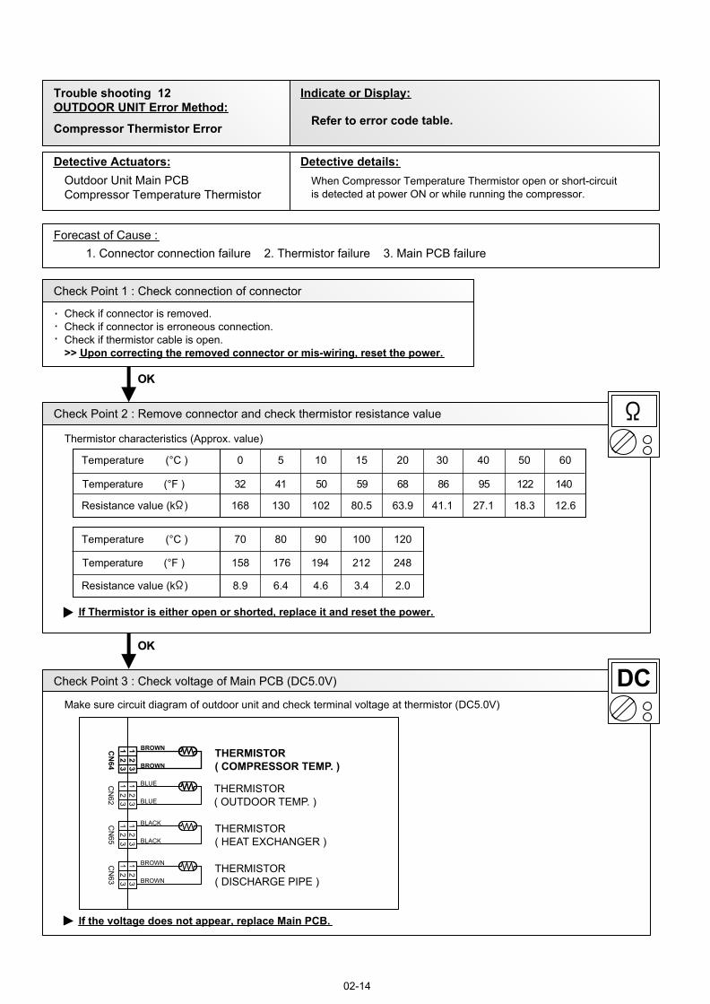
Trouble shooting 12 OUTDOOR UNIT Error Method:
Indicate or Display:
Detective Actuators: Detective details:
Forecast of Cause :
OKOK
OKOK
Compressor Thermistor Error
Outdoor Unit Main PCBCompressor Temperature Thermistor
When Compressor Temperature Thermistor open or short-circuit is detected at power ON or while running the compressor.
1. Connector connection failure 2. Thermistor failure 3. Main PCB failure
Check Point 1 : Check connection of connector
Check if connector is removed.Check if connector is erroneous connection.Check if thermistor cable is open. >> Upon correcting the removed connector or mis-wiring, reset the power.
Check Point 2 : Remove connector and check thermistor resistance value
Thermistor characteristics (Approx. value)
If Thermistor is either open or shorted, replace it and reset the power.
Check Point 3 : Check voltage of Main PCB (DC5.0V)
Make sure circuit diagram of outdoor unit and check terminal voltage at thermistor (DC5.0V)
If the voltage does not appear, replace Main PCB.
02-14
Refer to error code table.
BLACK
BLACK
BROWN
BROWN
BROWN
BROWN
BLUE
BLUE
CN
64C
N62
CN
65C
N63
12
31
23
12
31
23
12
31
23
12
31
23
THERMISTOR( DISCHARGE PIPE )
THERMISTOR( HEAT EXCHANGER )
THERMISTOR( OUTDOOR TEMP. )
THERMISTOR( COMPRESSOR TEMP. )
18.327.1
20
41.163.980.5102130168Resistance value (k )
151050Temperature (°C )
12.6
30 5040 60
2.03.44.66.48.9Resistance value (k )
120100908070Temperature (°C )
Temperature (°F ) 32 41 50 59 68 86 95 122 140
Temperature (°F ) 158 176 194 212 248
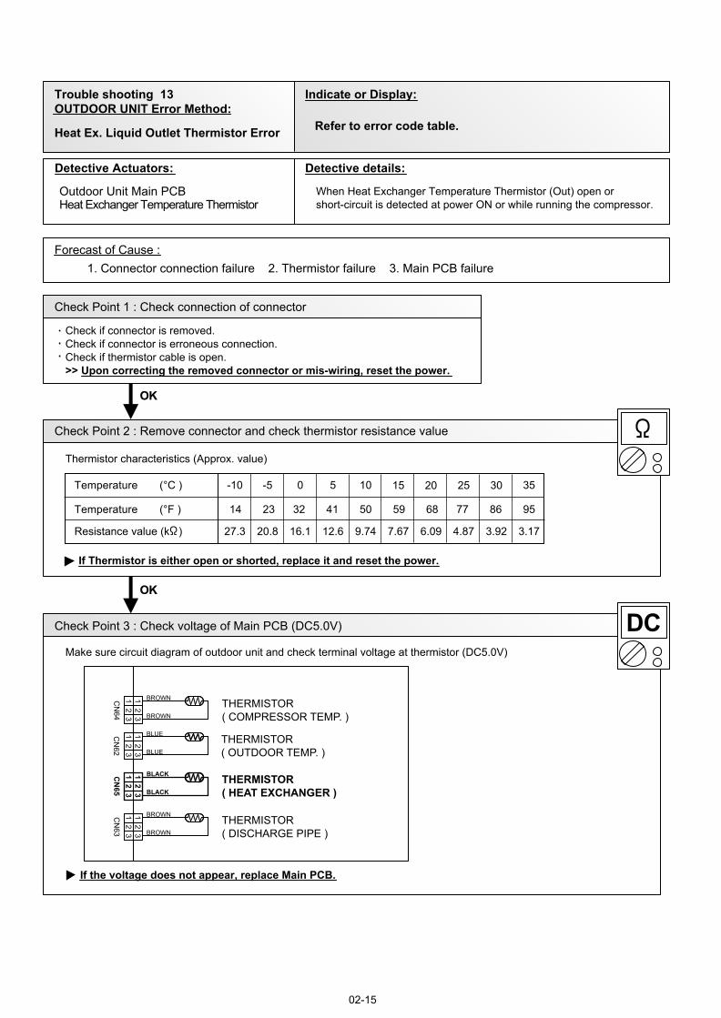
Trouble shooting 13 OUTDOOR UNIT Error Method:
Indicate or Display:
Detective Actuators: Detective details:
Forecast of Cause :
OKOK
OKOK
3.924.87
15
6.097.679.7416.120.827.3Resistance value (k )
100-5-10Temperature (°C ) 20 3025
Heat Ex. Liquid Outlet Thermistor Error
Outdoor Unit Main PCBHeat Exchanger Temperature Thermistor
When Heat Exchanger Temperature Thermistor (Out) open or short-circuit is detected at power ON or while running the compressor.
1. Connector connection failure 2. Thermistor failure 3. Main PCB failure
Check Point 1 : Check connection of connector
Check if connector is removed.Check if connector is erroneous connection.Check if thermistor cable is open. >> Upon correcting the removed connector or mis-wiring, reset the power.
Check Point 2 : Remove connector and check thermistor resistance value
Thermistor characteristics (Approx. value)
If Thermistor is either open or shorted, replace it and reset the power.
Check Point 3 : Check voltage of Main PCB (DC5.0V)
Make sure circuit diagram of outdoor unit and check terminal voltage at thermistor (DC5.0V)
If the voltage does not appear, replace Main PCB.
02-15
Refer to error code table.
BLACK
BLACK
BROWN
BROWN
BROWN
BROWN
BLUE
BLUE
CN
64C
N62
CN
65C
N63
12
31
23
12
31
23
12
31
23
12
31
23
THERMISTOR( DISCHARGE PIPE )
THERMISTOR( HEAT EXCHANGER )
THERMISTOR( OUTDOOR TEMP. )
THERMISTOR( COMPRESSOR TEMP. )
3.17
35
12.6
5
Temperature (°F ) 14 23 32 41 50 59 68 77 86 95
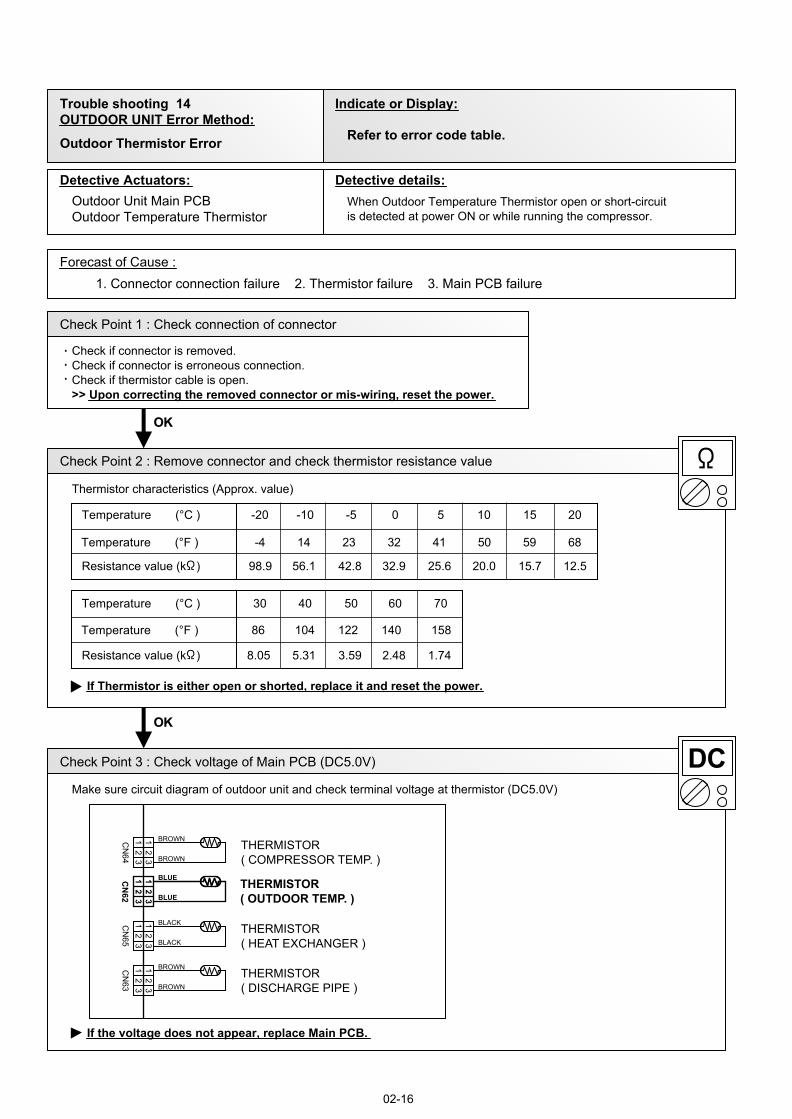
Trouble shooting 14 OUTDOOR UNIT Error Method:
Indicate or Display:
Detective Actuators: Detective details:
Forecast of Cause :
OKOK
OKOK
12.515.7
5
20.025.632.942.856.198.9Resistance value (k )
0-5-10-20Temperature (°C ) 10 2015
1.742.483.595.318.05Resistance value (k )
7060504030Temperature (°C )
Outdoor Thermistor Error
Outdoor Unit Main PCBOutdoor Temperature Thermistor
When Outdoor Temperature Thermistor open or short-circuit is detected at power ON or while running the compressor.
1. Connector connection failure 2. Thermistor failure 3. Main PCB failure
Check Point 1 : Check connection of connector
Check if connector is removed.Check if connector is erroneous connection.Check if thermistor cable is open. >> Upon correcting the removed connector or mis-wiring, reset the power.
Check Point 2 : Remove connector and check thermistor resistance value
Thermistor characteristics (Approx. value)
If Thermistor is either open or shorted, replace it and reset the power.
Check Point 3 : Check voltage of Main PCB (DC5.0V)
Make sure circuit diagram of outdoor unit and check terminal voltage at thermistor (DC5.0V)
If the voltage does not appear, replace Main PCB.
02-16
Refer to error code table.
BLACK
BLACK
BROWN
BROWN
BROWN
BROWN
BLUE
BLUE
CN
64C
N62
CN
65C
N63
12
31
23
12
31
23
12
31
23
12
31
23
THERMISTOR( DISCHARGE PIPE )
THERMISTOR( HEAT EXCHANGER )
THERMISTOR( OUTDOOR TEMP. )
THERMISTOR( COMPRESSOR TEMP. )
Temperature (°F ) -4 14 23 32 41 50 59 68
Temperature (°F ) 86 104 122 140 158
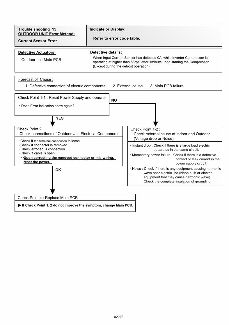
Trouble shooting 15OUTDOOR UNIT Error Method:
Current Sensor Error
02-17
Indicate or Display:
Refer to error code table.
Detective Actuators: Detective details:
Forecast of Cause :
Check Point 4 : Replace Main PCB
YES
NO
OK
Outdoor unit Main PCB
Check Point 2 : Check connections of Outdoor Unit Electrical Components
Check if connector is removed.Check if the terminal connection is loose.
Check erroneous connection.Check if cable is open.>>Upon correcting the removed connector or mis-wiring, reset the power.
Check Point 1-2 : Check external cause at Indoor and Outdoor (Voltage drop or Noise)
1. Defective connection of electric components 2. External cause 3. Main PCB failure
Instant drop : Check if there is a large load electric apparatus in the same circuit.Momentary power failure : Check if there is a defective contact or leak current in the power supply circuit.Noise : Check if there is any equipment causing harmonic wave near electric line.(Neon bulb or electric equipment that may cause harmonic wave) Check the complete insulation of grounding.
Check Point 1-1 : Reset Power Supply and operate
Does Error indication show again?
When Input Current Sensor has detected 0A, while Inverter Compressor is operating at higher than 56rps, after 1minute upon starting the Compressor. (Except during the defrost operation)
If Check Point 1, 2 do not improve the symptom, change Main PCB.
02-19
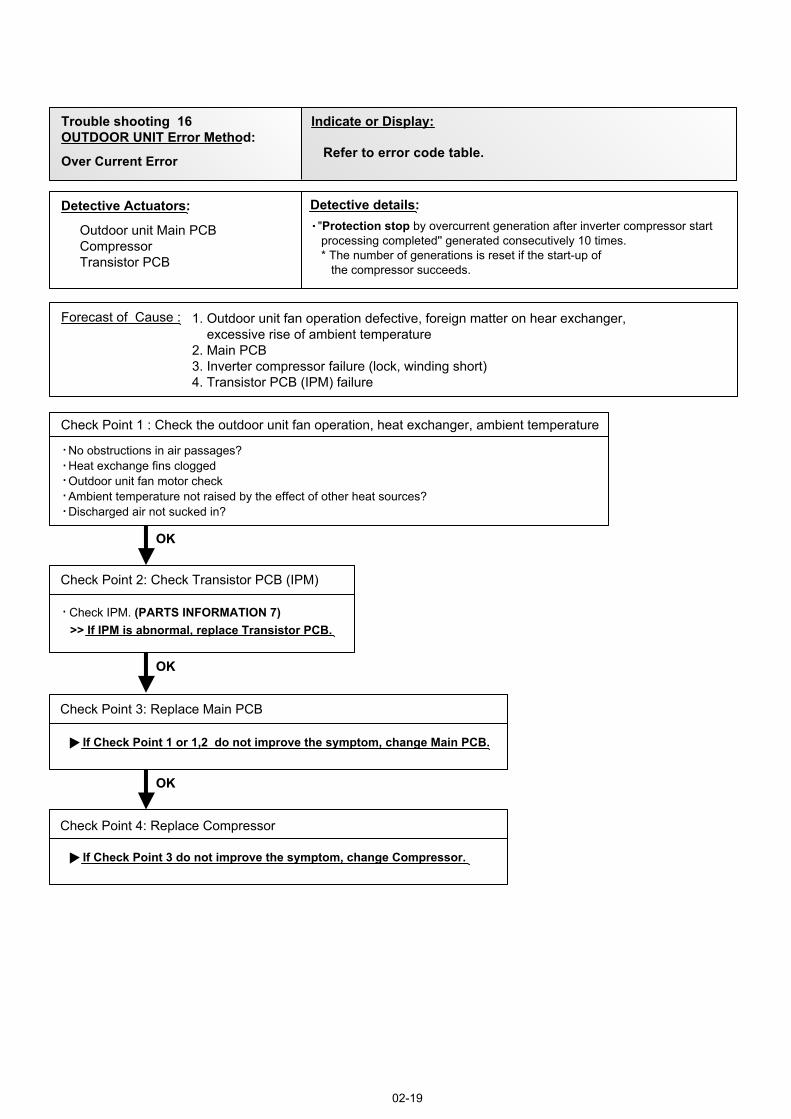
Trouble shooting 16OUTDOOR UNIT Error Method:
Indicate or Display:
Over Current Error Refer to error code table.
Detective Actuators: Detective details:
Forecast of Cause :
OKOK
OKOK
Check Point 3: Replace Main PCB
Outdoor unit Main PCBCompressorTransistor PCB
If Check Point 1 or 1,2 do not improve the symptom, change Main PCB.
Check Point 2: Check Transistor PCB (IPM)
>> If IPM is abnormal, replace Transistor PCB.
OKOK
Check Point 4: Replace Compressor
If Check Point 3 do not improve the symptom, change Compressor.
1. Outdoor unit fan operation defective, foreign matter on hear exchanger, excessive rise of ambient temperature2. Main PCB3. Inverter compressor failure (lock, winding short)4. Transistor PCB (IPM) failure
"Protection stop by overcurrent generation after inverter compressor start processing completed'' generated consecutively 10 times. * The number of generations is reset if the start-up of the compressor succeeds.
No obstructions in air passages?Heat exchange fins cloggedOutdoor unit fan motor checkAmbient temperature not raised by the effect of other heat sources?Discharged air not sucked in?
Check Point 1 : Check the outdoor unit fan operation, heat exchanger, ambient temperature
Check IPM. (PARTS INFORMATION 7)
Trouble shooting 17 OUTDOOR UNIT Error Method:
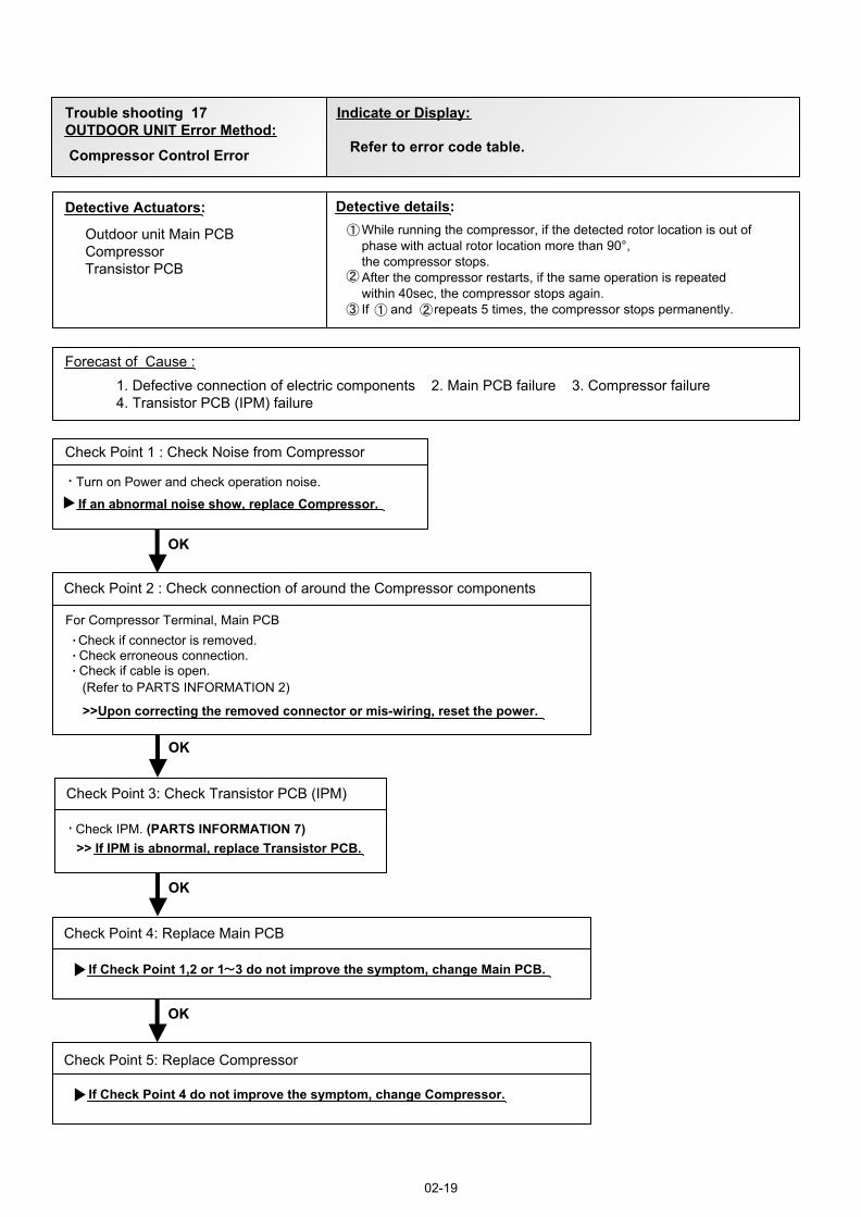
Compressor Control Error
02-19
Detective Actuators: Detective details:
Forecast of Cause :
Check Point 2 : Check connection of around the Compressor components
OKOK
Check Point 4: Replace Main PCB
Outdoor unit Main PCBCompressorTransistor PCB
1. Defective connection of electric components 2. Main PCB failure 3. Compressor failure4. Transistor PCB (IPM) failure
If Check Point 1,2 or 1 3 do not improve the symptom, change Main PCB.
Check if connector is removed.Check erroneous connection.Check if cable is open.
>>Upon correcting the removed connector or mis-wiring, reset the power.
(Refer to PARTS INFORMATION 2)
For Compressor Terminal, Main PCB
While running the compressor, if the detected rotor location is out of phase with actual rotor location more than 90°,the compressor stops.After the compressor restarts, if the same operation is repeated within 40sec, the compressor stops again.If and repeats 5 times, the compressor stops permanently.
Check Point 1 : Check Noise from Compressor
Turn on Power and check operation noise.
If an abnormal noise show, replace Compressor.
OKOK
Check Point 5: Replace Compressor
If Check Point 4 do not improve the symptom, change Compressor.
OKOK
OKOK
Check Point 3: Check Transistor PCB (IPM)
>> If IPM is abnormal, replace Transistor PCB.Check IPM. (PARTS INFORMATION 7)
Indicate or Display:
Refer to error code table.
02-20
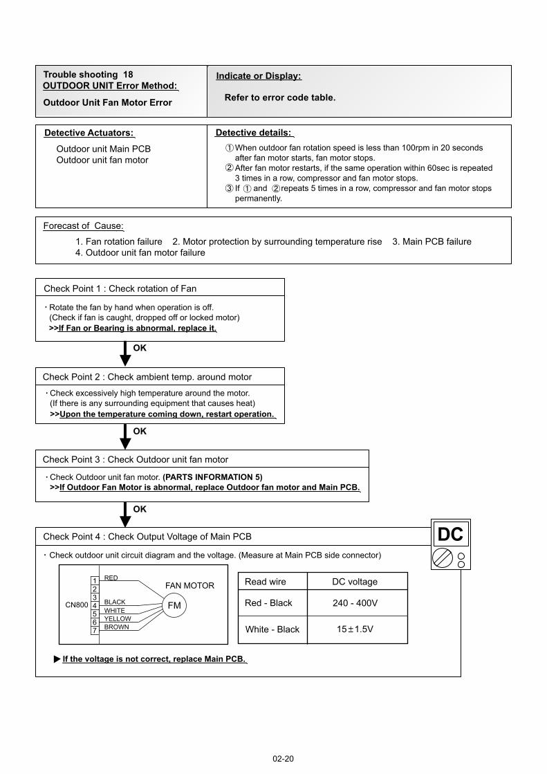
Trouble shooting 18OUTDOOR UNIT Error Method:
Detective Actuators: Detective details:
Forecast of Cause:
Check Point 3 : Check Outdoor unit fan motor
OK
OK
Outdoor Unit Fan Motor Error
Outdoor unit Main PCBOutdoor unit fan motor
1. Fan rotation failure 2. Motor protection by surrounding temperature rise 3. Main PCB failure4. Outdoor unit fan motor failure
Check Point 1 : Check rotation of Fan
Rotate the fan by hand when operation is off.(Check if fan is caught, dropped off or locked motor)>>If Fan or Bearing is abnormal, replace it.
Check Outdoor unit fan motor. (PARTS INFORMATION 5)>>If Outdoor Fan Motor is abnormal, replace Outdoor fan motor and Main PCB.
Check Point 4 : Check Output Voltage of Main PCB
Check outdoor unit circuit diagram and the voltage. (Measure at Main PCB side connector)
If the voltage is not correct, replace Main PCB.
When outdoor fan rotation speed is less than 100rpm in 20 seconds after fan motor starts, fan motor stops.After fan motor restarts, if the same operation within 60sec is repeated 3 times in a row, compressor and fan motor stops.If and repeats 5 times in a row, compressor and fan motor stops permanently.
Read wire DC voltage
Red - Black 240 - 400V
White - Black 15 1.5V
CN800
1234567
BLACKWHITEYELLOWBROWN
RED
FM
FAN MOTOR
Check Point 2 : Check ambient temp. around motor
OK
Check excessively high temperature around the motor.(If there is any surrounding equipment that causes heat)>>Upon the temperature coming down, restart operation.
Indicate or Display:
Refer to error code table.
Detective Actuators: Detective details:
Forecast of Cause :
OKOK
OKOK
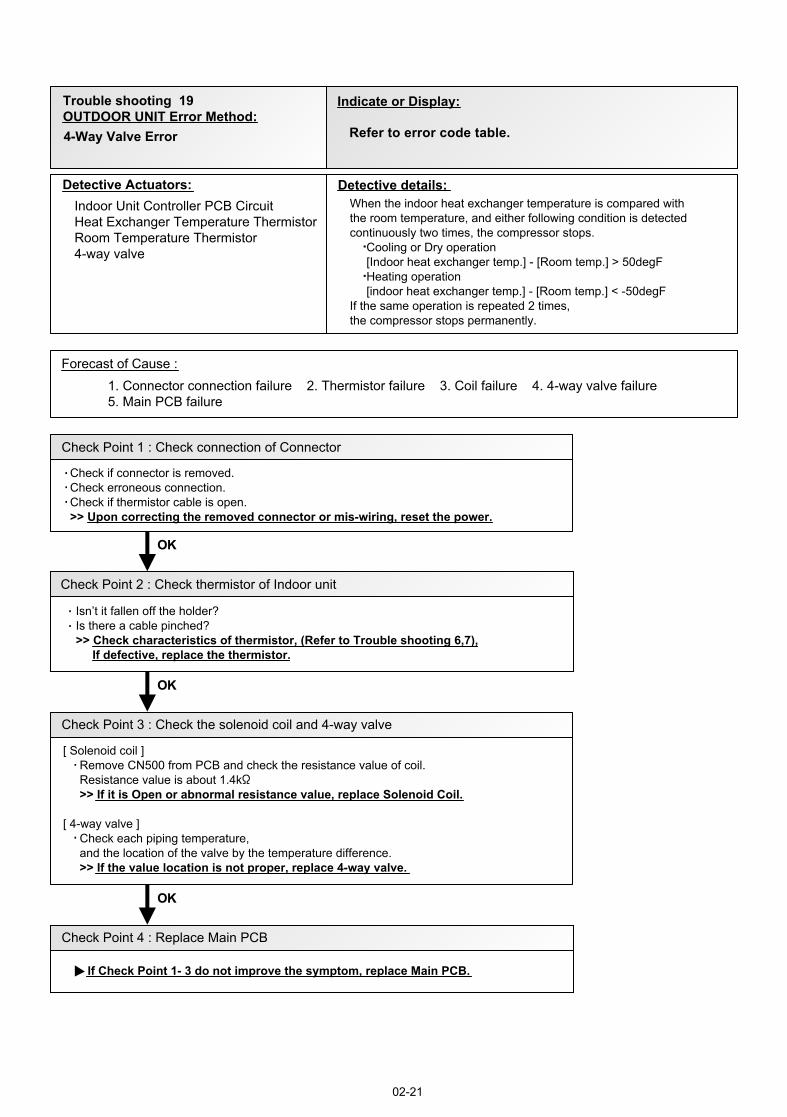
1. Connector connection failure 2. Thermistor failure 3. Coil failure 4. 4-way valve failure5. Main PCB failure
Check Point 1 : Check connection of Connector
Check if connector is removed. Check erroneous connection. Check if thermistor cable is open. >> Upon correcting the removed connector or mis-wiring, reset the power.
Check Point 3 : Check the solenoid coil and 4-way valve
02-21
[ Solenoid coil ] Remove CN500 from PCB and check the resistance value of coil. Resistance value is about 1.4k >> If it is Open or abnormal resistance value, replace Solenoid Coil.
[ 4-way valve ] Check each piping temperature, and the location of the valve by the temperature difference. >> If the value location is not proper, replace 4-way valve.
OKOK
Check Point 4 : Replace Main PCB
If Check Point 1- 3 do not improve the symptom, replace Main PCB.
Check Point 2 : Check thermistor of Indoor unit
Isn’t it fallen off the holder?Is there a cable pinched? >> Check characteristics of thermistor, (Refer to Trouble shooting 6,7), If defective, replace the thermistor.
Indoor Unit Controller PCB CircuitHeat Exchanger Temperature ThermistorRoom Temperature Thermistor4-way valve
When the indoor heat exchanger temperature is compared withthe room temperature, and either following condition is detected continuously two times, the compressor stops. Cooling or Dry operation [Indoor heat exchanger temp.] - [Room temp.] > 50degF Heating operation [indoor heat exchanger temp.] - [Room temp.] < -50degFIf the same operation is repeated 2 times, the compressor stops permanently.
Trouble shooting 19OUTDOOR UNIT Error Method:4-Way Valve Error
Indicate or Display:
Refer to error code table.
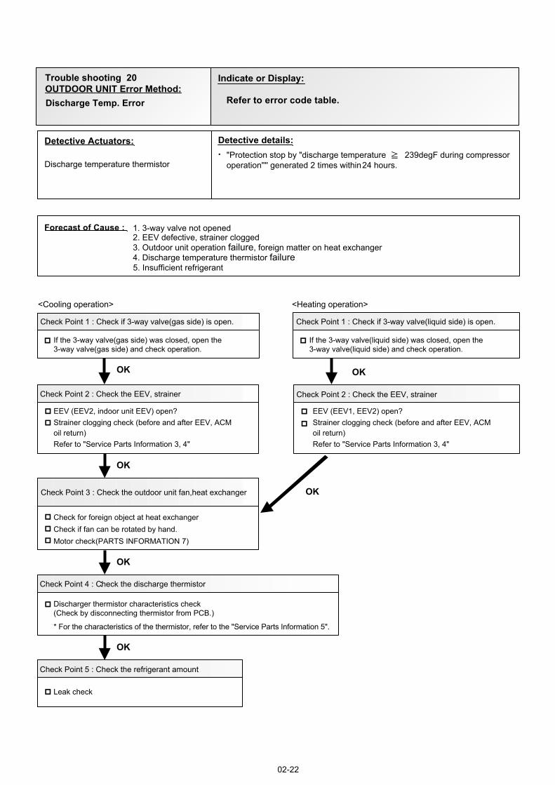
<Cooling operation>
OK
OK
OK
OK
:
OK
<Heating operation>
2. EEV defective, strainer clogged3. Outdoor unit operation failure, foreign matter on heat exchanger4. Discharge temperature thermistor failure5. Insufficient refrigerant
Discharge temperature thermistor"Protection stop by "discharge temperature 239degF during compressoroperation'''' generated 2 times within 24 hours.
Check Point 1 : Check if 3-way valve(gas side) is open.
Discharger thermistor characteristics check(Check by disconnecting thermistor from PCB.)
* For the characteristics of the thermistor, refer to the "Service Parts Information 5".
Check Point 4 : Check the discharge thermistor
EEV (EEV2, indoor unit EEV) open?Strainer clogging check (before and after EEV, ACM oil return)Refer to "Service Parts Information 3, 4 "
Check Point 3 : Check the outdoor unit fan,heat exchanger
Check for foreign object at heat exchangerCheck if fan can be rotated by hand.Motor check(PARTS INFORMATION 7)
Check Point 2 : Check the EEV, strainer
Check Point 5 : Check the refrigerant amount
Leak check
EEV (EEV1, EEV2) open?Strainer clogging check (before and after EEV, ACM oil return)Refer to "Service Parts Information 3, 4"
Check Point 2 : Check the EEV, strainer
If the 3-way valve(gas side) was closed, open the 3-way valve(gas side) and check operation.
02-22
Check Point 1 : Check if 3-way valve(liquid side) is open.
If the 3-way valve(liquid side) was closed, open the 3-way valve(liquid side) and check operation.
OK
1. 3-way valve not opened
Detective Actuators: Detective details:
Forecast of Cause :
Trouble shooting 20OUTDOOR UNIT Error Method:Discharge Temp. Error
Indicate or Display:
Refer to error code table.
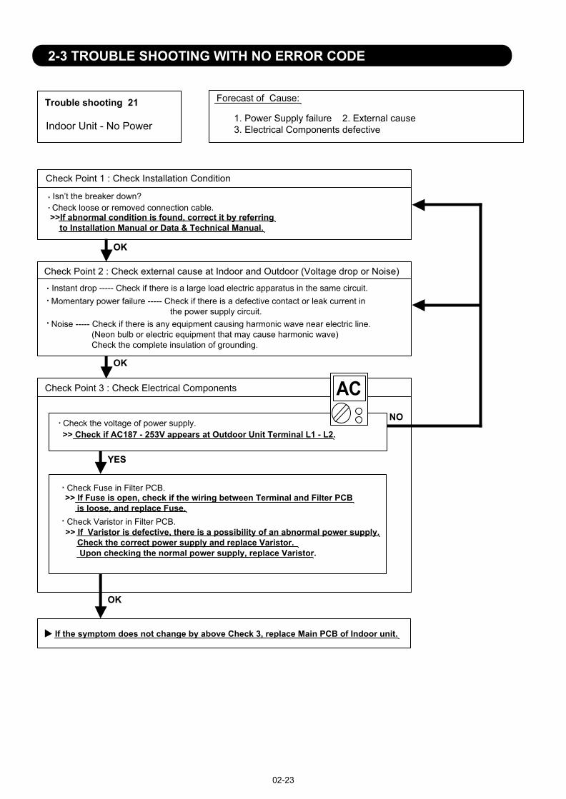
Trouble shooting 21 Forecast of Cause:
OKOK
Indoor Unit - No Power 1. Power Supply failure 2. External cause 3. Electrical Components defective
Check Point 1 : Check Installation Condition
Isn’t the breaker down?Check loose or removed connection cable.>>If abnormal condition is found, correct it by referring to Installation Manual or Data & Technical Manual.
Check Point 2 : Check external cause at Indoor and Outdoor (Voltage drop or Noise)
Instant drop ----- Check if there is a large load electric apparatus in the same circuit.Momentary power failure ----- Check if there is a defective contact or leak current in the power supply circuit.Noise ----- Check if there is any equipment causing harmonic wave near electric line. (Neon bulb or electric equipment that may cause harmonic wave) Check the complete insulation of grounding.
02-23
2-3 TROUBLE SHOOTING WITH NO ERROR CODE
Check Point 3 : Check Electrical Components
YESYES
OK
NOCheck the voltage of power supply.>> Check if AC187 - 253V appears at Outdoor Unit Terminal L1 - L2.
Check Varistor in Filter PCB.>> If Varistor is defective, there is a possibility of an abnormal power supply. Check the correct power supply and replace Varistor. Upon checking the normal power supply, replace Varistor.
If the symptom does not change by above Check 3, replace Main PCB of Indoor unit.
OK
Check Fuse in Filter PCB. >> If Fuse is open, check if the wiring between Terminal and Filter PCB is loose, and replace Fuse.
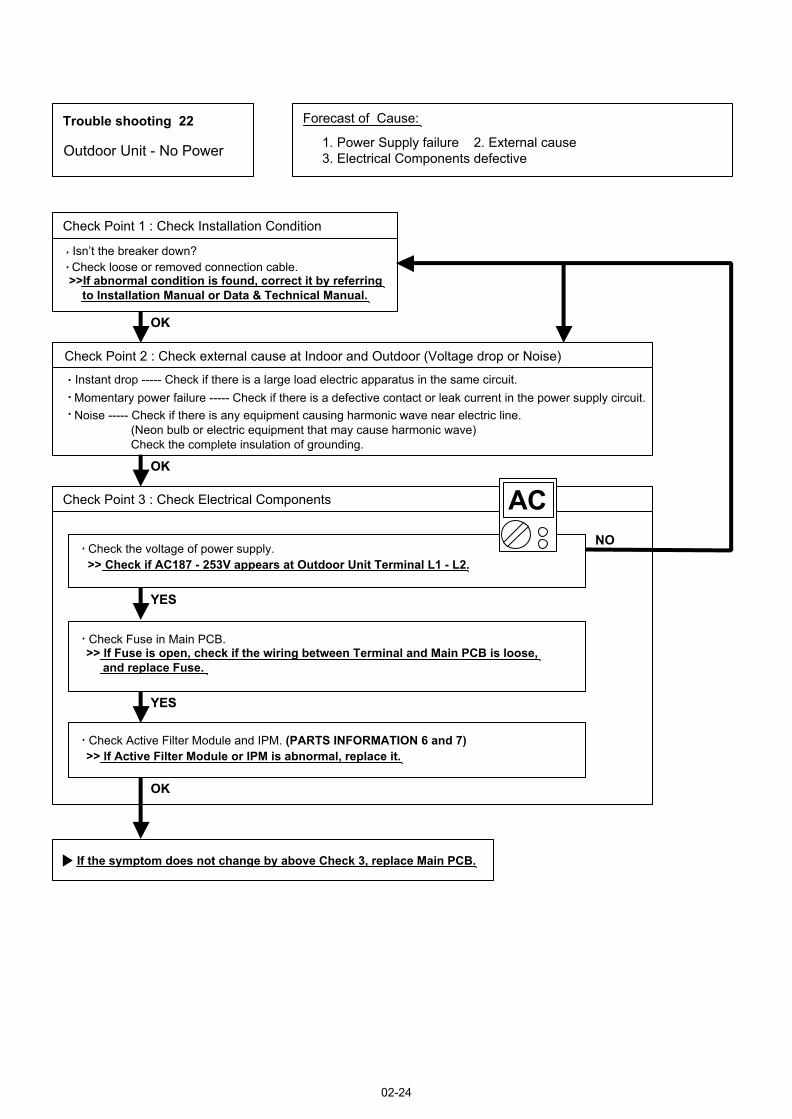
Trouble shooting 22 Forecast of Cause:
Check Point 3 : Check Electrical Components
OKOK
OKOK
YESYES
YESYES
OK
NO
Check Point 1 : Check Installation Condition
Outdoor Unit - No Power 1. Power Supply failure 2. External cause 3. Electrical Components defective
Isn’t the breaker down?Check loose or removed connection cable.>>If abnormal condition is found, correct it by referring to Installation Manual or Data & Technical Manual.
Check Point 2 : Check external cause at Indoor and Outdoor (Voltage drop or Noise)
Instant drop ----- Check if there is a large load electric apparatus in the same circuit.Momentary power failure ----- Check if there is a defective contact or leak current in the power supply circuit.Noise ----- Check if there is any equipment causing harmonic wave near electric line. (Neon bulb or electric equipment that may cause harmonic wave) Check the complete insulation of grounding.
Check the voltage of power supply.>> Check if AC187 - 253V appears at Outdoor Unit Terminal L1 - L2.
Check Fuse in Main PCB.>> If Fuse is open, check if the wiring between Terminal and Main PCB is loose, and replace Fuse.
Check Active Filter Module and IPM. (PARTS INFORMATION 6 and 7)>> If Active Filter Module or IPM is abnormal, replace it.
If the symptom does not change by above Check 3, replace Main PCB.
02-24
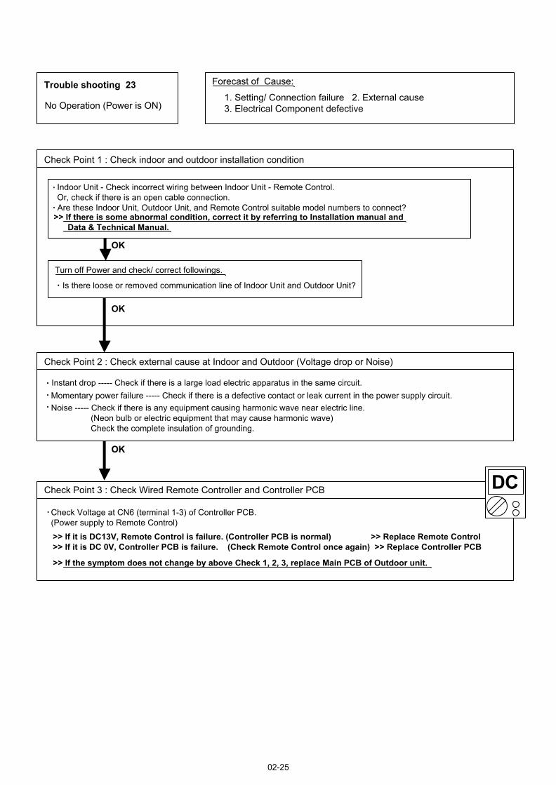
Trouble shooting 23 Forecast of Cause:
Check Point 2 : Check external cause at Indoor and Outdoor (Voltage drop or Noise)
Check Point 1 : Check indoor and outdoor installation condition
Check Point 3 : Check Wired Remote Controller and Controller PCB
OK
OK
OKOK
No Operation (Power is ON)1. Setting/ Connection failure 2. External cause 3. Electrical Component defective
Indoor Unit - Check incorrect wiring between Indoor Unit - Remote Control.Or, check if there is an open cable connection.Are these Indoor Unit, Outdoor Unit, and Remote Control suitable model numbers to connect?
>> If there is some abnormal condition, correct it by referring to Installation manual and Data & Technical Manual.
Turn off Power and check/ correct followings.
Is there loose or removed communication line of Indoor Unit and Outdoor Unit?
Instant drop ----- Check if there is a large load electric apparatus in the same circuit.Momentary power failure ----- Check if there is a defective contact or leak current in the power supply circuit.Noise ----- Check if there is any equipment causing harmonic wave near electric line. (Neon bulb or electric equipment that may cause harmonic wave) Check the complete insulation of grounding.
>> If it is DC13V, Remote Control is failure. (Controller PCB is normal) >> Replace Remote Control>> If it is DC 0V, Controller PCB is failure. (Check Remote Control once again) >> Replace Controller PCB
>> If the symptom does not change by above Check 1, 2, 3, replace Main PCB of Outdoor unit.
02-25
Check Voltage at CN6 (terminal 1-3) of Controller PCB.(Power supply to Remote Control)
Attention
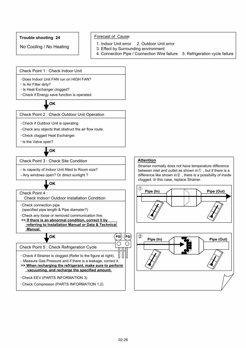
Trouble shooting 24 Forecast of Cause:
Check Point 2 : Check Outdoor Unit Operation
Check Point 1 : Check Indoor Unit
Check Point 3 : Check Site Condition
Check Point 5 : Check Refrigeration Cycle
Check Point 4 : Check Indoor/ Outdoor Installation Condition
Pipe (In) Pipe (Out)
Pipe (In) Pipe (Out)
OKOK
OKOK
OKOK
OKOK
PSI PSI
No Cooling / No Heating1. Indoor Unit error 2. Outdoor Unit error 3. Effect by Surrounding environment 4. Connection Pipe / Connection Wire failure 5. Refrigeration cycle failure
Does Indoor Unit FAN run on HIGH FAN?Is Air Filter dirty?Is Heat Exchanger clogged?Check if Energy save function is operated.
Check if Outdoor Unit is operating Check any objects that obstruct the air flow route.
Check clogged Heat Exchanger.
Is the Valve open?
Is capacity of Indoor Unit fitted to Room size?Any windows open? Or direct sunlight ?
Check connection pipe (specified pipe length & Pipe diameter?)Check any loose or removed communication line.>> If there is an abnormal condition, correct it by referring to Installation Manual or Data & Technical Manual.
Check if Strainer is clogged (Refer to the figure at right).Measure Gas Pressure and if there is a leakage, correct it.
>> When recharging the refrigerant, make sure to perform vacuuming, and recharge the specified amount.
Check EEV (PARTS INFORMATION 3)
Check Compressor (PARTS INFORMATION 1,2)
Strainer normally does not have temperature difference between inlet and outlet as shown in , but if there is a difference like shown in , there is a possibility of inside clogged. In this case, replace Strainer.
02-26
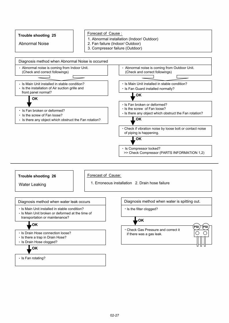
Trouble shooting 25 Forecast of Cause :
Trouble shooting 26 Forecast of Cause:
OKOK
OK
OK
OKOK
OKOK
OKOKPSI PSI
Abnormal Noise1. Abnormal installation (Indoor/ Outdoor) 2. Fan failure (Indoor/ Outdoor)3. Compressor failure (Outdoor)
Diagnosis method when Abnormal Noise is occurredAbnormal noise is coming from Indoor Unit.(Check and correct followings)
Abnormal noise is coming from Outdoor Unit.(Check and correct followings)
Is Fan broken or deformed?Is the screw of Fan loose?Is there any object which obstruct the Fan rotation?
Is Main Unit installed in stable condition?Is the installation of Air suction grille and front panel normal?
Is Fan broken or deformed?Is the screw of Fan loose?Is there any object which obstruct the Fan rotation?
Is Main Unit installed in stable condition?Is Fan Guard installed normally?
Check if vibration noise by loose bolt or contact noise of piping is happening.
Is Compressor locked?>> Check Compressor (PARTS INFORMATION 1,2)
Water Leaking 1. Erroneous installation 2. Drain hose failure
Diagnosis method when water is spitting out.
Is the filter clogged?
Check Gas Pressure and correct it if there was a gas leak.
Diagnosis method when water leak occurs
Is Drain Hose connection loose?Is there a trap in Drain Hose?Is Drain Hose clogged?
Is Main Unit installed in stable condition?Is Main Unit broken or deformed at the time of transportation or maintenance?
Is Fan rotating?
02-27
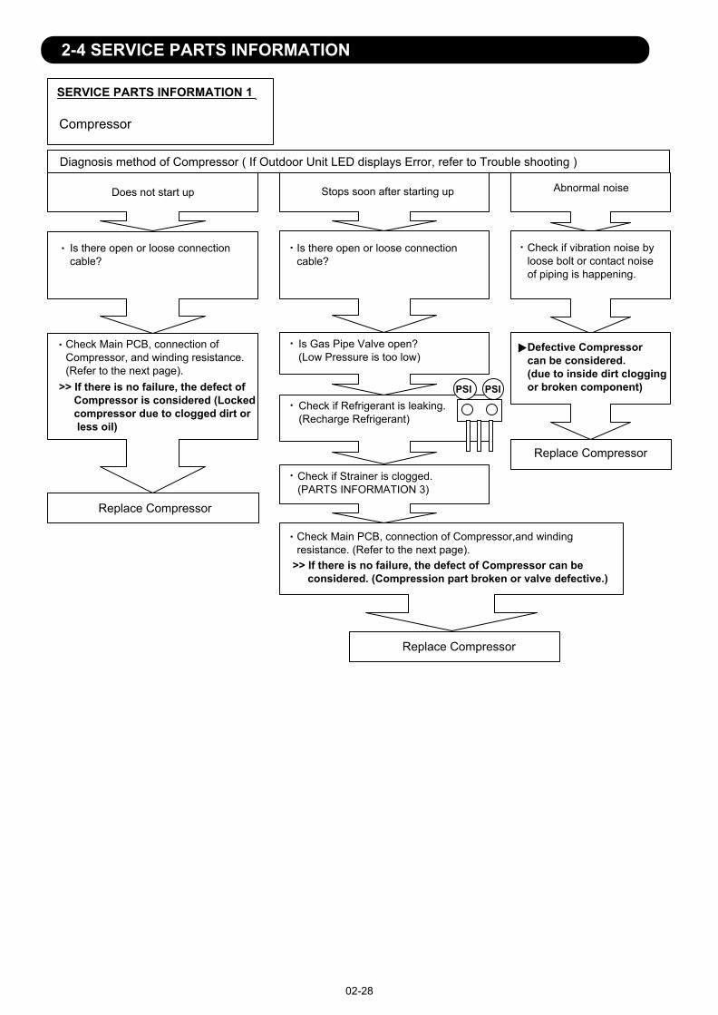
SERVICE PARTS INFORMATION 1
PSI PSI
Compressor
Diagnosis method of Compressor ( If Outdoor Unit LED displays Error, refer to Trouble shooting )
Does not start up
Is there open or loose connection cable?
Check Main PCB, connection of Compressor, and winding resistance. (Refer to the next page).
Check Main PCB, connection of Compressor,and winding resistance. (Refer to the next page).
>> If there is no failure, the defect of Compressor is considered (Locked compressor due to clogged dirt or less oil)
Replace Compressor
Replace Compressor
Replace Compressor
Stops soon after starting up
Is there open or loose connection cable?
Is Gas Pipe Valve open?(Low Pressure is too low)
Check if Refrigerant is leaking.(Recharge Refrigerant)
Check if Strainer is clogged.(PARTS INFORMATION 3)
>> If there is no failure, the defect of Compressor can be considered. (Compression part broken or valve defective.)
Abnormal noise
Defective Compressor can be considered.(due to inside dirt clogging or broken component)
Check if vibration noise by loose bolt or contact noise of piping is happening.
02-28
2-4 SERVICE PARTS INFORMATION
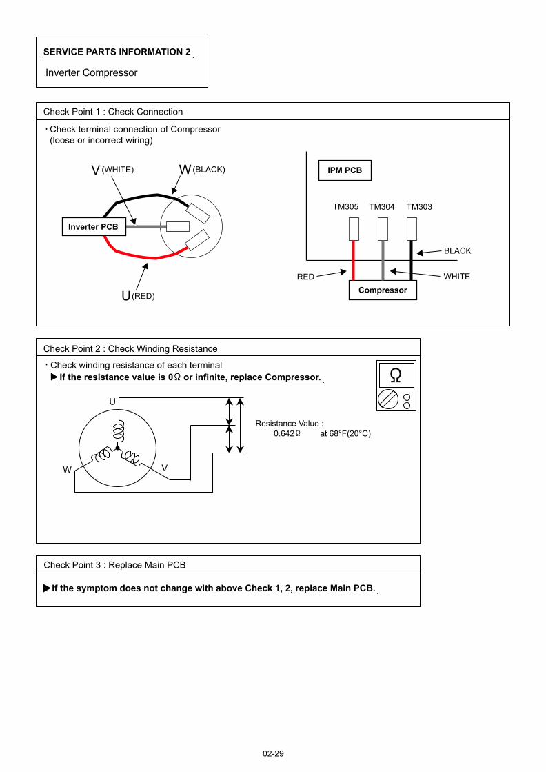
SERVICE PARTS INFORMATION 2
Check Point 1 : Check Connection
Check Point 2 : Check Winding Resistance
Check Point 3 : Replace Main PCB
U
VW
Inverter Compressor
Check terminal connection of Compressor(loose or incorrect wiring)
Check winding resistance of each terminalIf the resistance value is 0 or infinite, replace Compressor.
If the symptom does not change with above Check 1, 2, replace Main PCB.
02-29
Resistance Value : 0.642 ± at 68°F(20°C)
U(RED)
V (WHITE) W(BLACK) IPM PCB
TM303TM304TM305
RED WHITE
BLACK
Compressor
Inverter PCB
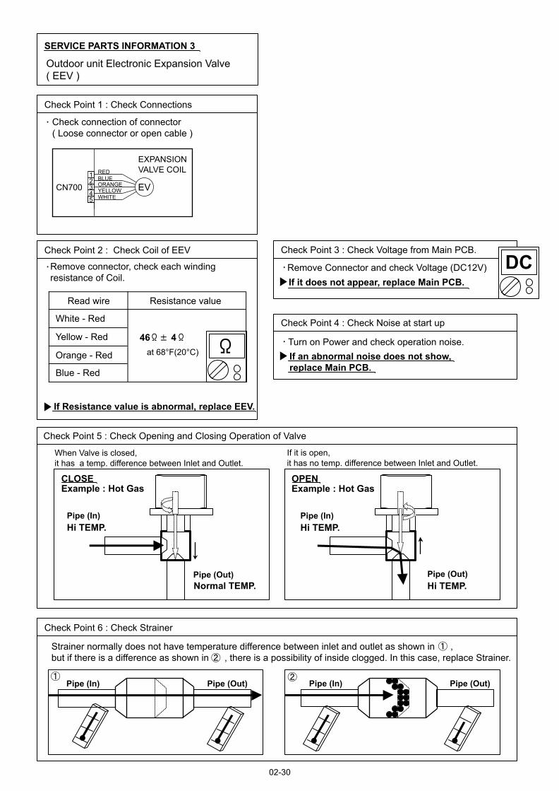
SERVICE PARTS INFORMATION 3
Check Point 2 : Check Coil of EEV
Yellow - Red
Orange - Red
Blue - Red
White - Red
Read wire
46 4
Resistance value
Check Point 1 : Check Connections
Check Point 5 : Check Opening and Closing Operation of Valve
Check Point 3 : Check Voltage from Main PCB.
Check Point 4 : Check Noise at start up
Pipe (In)
Pipe (Out)
Hi TEMP.Pipe (In)Hi TEMP.
Normal TEMP.
CLOSEExample : Hot Gas
OPENExample : Hot Gas
Pipe (Out)Hi TEMP.
Pipe (In) Pipe (Out)Pipe (In) Pipe (Out)
Check Point 6 : Check Strainer
DC
at 68°F(20°C)
Outdoor unit Electronic Expansion Valve( EEV )
Check connection of connector( Loose connector or open cable )
Remove connector, check each winding resistance of Coil.
If Resistance value is abnormal, replace EEV.
Remove Connector and check Voltage (DC12V)If it does not appear, replace Main PCB.
Turn on Power and check operation noise.If an abnormal noise does not show, replace Main PCB.
When Valve is closed, it has a temp. difference between Inlet and Outlet.
If it is open, it has no temp. difference between Inlet and Outlet.
Strainer normally does not have temperature difference between inlet and outlet as shown in , but if there is a difference as shown in , there is a possibility of inside clogged. In this case, replace Strainer.
02-30
CN700
EXPANSIONVALVE COIL
EV
REDBLUEORANGEYELLOWWHITE
12345
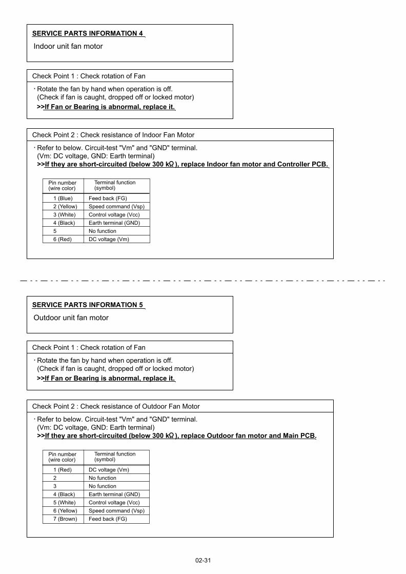
SERVICE PARTS INFORMATION 5
Check Point 1 : Check rotation of Fan
Outdoor unit fan motor
Rotate the fan by hand when operation is off.(Check if fan is caught, dropped off or locked motor)>>If Fan or Bearing is abnormal, replace it.
Check Point 2 : Check resistance of Outdoor Fan Motor
Refer to below. Circuit-test "Vm" and "GND" terminal.(Vm: DC voltage, GND: Earth terminal)>>If they are short-circuited (below 300 k ), replace Outdoor fan motor and Main PCB.
Pin number (wire color)
Terminal function (symbol)
1 (Red)234 (Black)5 (White)6 (Yellow)7 (Brown)
DC voltage (Vm)No functionNo functionEarth terminal (GND)Control voltage (Vcc)Speed command (Vsp)Feed back (FG)
SERVICE PARTS INFORMATION 4
Check Point 1 : Check rotation of Fan
Indoor unit fan motor
Rotate the fan by hand when operation is off.(Check if fan is caught, dropped off or locked motor)>>If Fan or Bearing is abnormal, replace it.
Check Point 2 : Check resistance of Indoor Fan Motor
Refer to below. Circuit-test "Vm" and "GND" terminal.(Vm: DC voltage, GND: Earth terminal)>>If they are short-circuited (below 300 k ), replace Indoor fan motor and Controller PCB.
Pin number (wire color)
Terminal function (symbol)
1 (Blue)2 (Yellow)3 (White)4 (Black)56 (Red)
Feed back (FG)Speed command (Vsp)Control voltage (Vcc)Earth terminal (GND)No functionDC voltage (Vm)
02-31
SERVICE PARTS INFORMATION 6
Active filter module
02-32
Check Point 1 : Check Open or Short-circuit and Diode (D1)
Check Point 2 : Check the Output DC voltage (between P and N)
L2L1
P
N
+IN
Check the Output DC voltage (between P and N) of compressor stopping and operating.
If it is abnormal,replace ACTIVE FILTER MODULE
Remove connector, check the open or short-circuit and the diode in the module
>> If the output voltage of compressor operating is less than the output voltage of compressor stopping, Active Filter Module is detective. >> Replace Active Filter Module
TerminalResistance value
L2L1
L1,L2
P
P
Control Box
N
N
(+IN)
(+IN)
( IN)
( IN)
Tester(+) Tester(-)
Check the open or short-circuit
L2
P
P
NL2
L2
Check the diode
0
360k
720k
1.69M /
20%+-
360k 20%+-
20%+-
(Ref. value 1)1.88M(Ref. value 2)
1.40M /(Ref. value 1)
2.28M(Ref. value 2)
TerminalResistance value
Tester(+) Tester(-)
1.32M /(Ref. value 1)
1.50M(Ref. value 2)
1.40M /(Ref. value 1)
1.51M(Ref. value 2)
Ref. value 1Specifications for Multimeter Manufacturer : HIOKI Model name : 3804 Power source : DC9V.
Ref. value 2Specifications for Multimeter Manufacturer : YOKOGAWA Model name : 7534 Power source : DC3V.
-IN
SERVICE PARTS INFORMATION 7IPM(Mounted on Transistor PCB)
02-33
Check Point 1
Check Point 2
Terminal Resistance value Tester(+) Tester(-)
Disconnect the connection wires between the Transistor PCB - Capacitor PCB and Transistor PCB - Inverter Compressor.
Set the tester to the "Resistance" mode, and measure the resistance between the following terminals.
Set the tester to the "Diode" mode, and measure the voltage value between the following terminals.
Judge the result of as follows:
Judge the result of as follows:
TM301 (P) - TM305(U) / TM304(V) / TM303(W)TM302 (N) - TM305(U) / TM304(V) / TM303(W)
PPPUVWNNNUVW
UVWPPPUVWNNN
Over 2k(Including )
Over 2k(Including )
Over 20k(Including )
Terminal Tester display Tester(+) Tester(-)
PPPUVWNNNUVW
UVWPPPUVWNNN
0.3V 0.7V
3 . APPENDING DATA
R410A
WALL MOUNTED typeINVERTER
1. FUNCTION SETTING
2. OUTDOOR UNIT PRESSURE VALUE AND TOTAL ELECTRIC CURRENT CURVE
3. THERMISTOR RESISTANCE VALUES
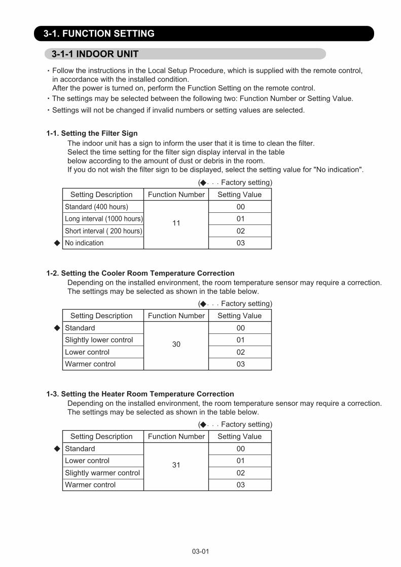
03-01
3-1. FUNCTION SETTING
Follow the instructions in the Local Setup Procedure, which is supplied with the remote control, in accordance with the installed condition.After the power is turned on, perform the Function Setting on the remote control.The settings may be selected between the following two: Function Number or Setting Value.Settings will not be changed if invalid numbers or setting values are selected.
3-1-1 INDOOR UNIT
( Factory setting)Setting Description Function Number Setting Value
Standard (400 hours)Long interval (1000 hours)Short interval ( 200 hours)No indication
11
00010203
1-1. Setting the Filter SignThe indoor unit has a sign to inform the user that it is time to clean the filter. Select the time setting for the filter sign display interval in the table below according to the amount of dust or debris in the room. If you do not wish the filter sign to be displayed, select the setting value for "No indication".
( Factory setting)Setting Description Function Number Setting Value
StandardSlightly lower controlLower controlWarmer control
30
00010203
1-2. Setting the Cooler Room Temperature CorrectionDepending on the installed environment, the room temperature sensor may require a correction.The settings may be selected as shown in the table below.
( Factory setting)Setting Description Function Number Setting Value
StandardLower controlSlightly warmer controlWarmer control
31
00010203
1-3. Setting the Heater Room Temperature CorrectionDepending on the installed environment, the room temperature sensor may require a correction.The settings may be selected as shown in the table below.
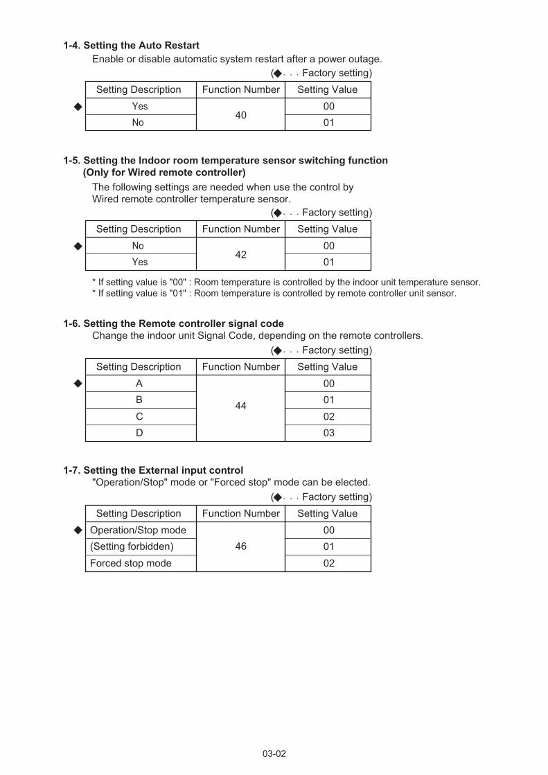
03-02
( Factory setting)Setting Description Function Number Setting Value
YesNo
400001
( Factory setting)Setting Description Function Number Setting Value
NoYes
420001
1-4. Setting the Auto RestartEnable or disable automatic system restart after a power outage.
1-5. Setting the Indoor room temperature sensor switching function (Only for Wired remote controller)
The following settings are needed when use the control by Wired remote controller temperature sensor.
( Factory setting)Setting Description Function Number Setting Value
ABCD
44
00010203
1-6. Setting the Remote controller signal codeChange the indoor unit Signal Code, depending on the remote controllers.
( Factory setting)Setting Description Function Number Setting Value
Operation/Stop mode(Setting forbidden)Forced stop mode
46000102
1-7. Setting the External input control"Operation/Stop" mode or "Forced stop" mode can be elected.
* If setting value is "00" : Room temperature is controlled by the indoor unit temperature sensor.* If setting value is "01" : Room temperature is controlled by remote controller unit sensor.
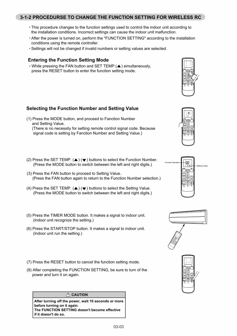
MIN.HEAT
MIN.HEAT
MIN.HEAT
03-03
Settings will not be changed if invalid numbers or setting values are selected.
After the power is turned on, perform the "FUNCTION SETTING" according to the installation conditions using the remote controller.
This procedure changes to the function settings used to control the indoor unit according to the installation conditions. Incorrect settings can cause the indoor unit malfunction.
Entering the Function Setting ModeWhile pressing the FAN button and SET TEMP.( ) simultaneously, press the RESET button to enter the function setting mode.
3-1-2 PROCEDURSE TO CHANGE THE FUNCTION SETTING FOR WIRELESS RC
(2) Press the SET TEMP. ( ) ( ) buttons to select the Function Number. (Press the MODE button to switch between the left and right digits.)
(3) Press the FAN button to proceed to Setting Value. (Press the FAN button again to return to the Function Number selection.)
Selecting the Function Number and Setting Value
(6) Press the START/STOP button. It makes a signal to indoor unit. (Indoor unit run the setting.)
(7) Press the RESET button to cancel the function setting mode.
(8) After completing the FUNCTION SETTING, be sure to turn of the power and turn it on again.
CAUTION
After turning off the power, wait 10 seconds or more before turning on it again.The FUNCTION SETTING doesn't become effective if it doesn't do so.
(4) Press the SET TEMP. ( ) ( ) buttons to select the Setting Value. (Press the MODE button to switch between the left and right digits.)
Function Number
Setting Value
(1) Press the MODE button, and proceed to Fanction Number and Setting Value. (There is no necessity for setting remote control signal code. Because signal code is setting by Fanction Number and Setting Value.)
(5) Press the TIMER MODE button. It makes a signal to indoor unit. (Indoor unit recognize the setting.)
MIN.HEAT
MIN.HEAT
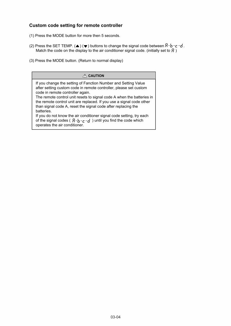
03-04
(1) Press the MODE button for more then 5 seconds.
(3) Press the MODE button. (Return to normal display)
Custom code setting for remote controller
(2) Press the SET TEMP. ( ) ( ) buttons to change the signal code between . Match the code on the display to the air conditioner signal code. (initially set to )
If you change the setting of Fanction Number and Setting Value after setting custom code in remote controller, please set custom code in remote controller again.The remote control unit resets to signal code A when the batteries in the remote control unit are replaced. If you use a signal code otherthan signal code A, reset the signal code after replacing thebatteries.If you do not know the air conditioner signal code setting, try eachof the signal codes ( ) until you find the code which operates the air conditioner.
CAUTION
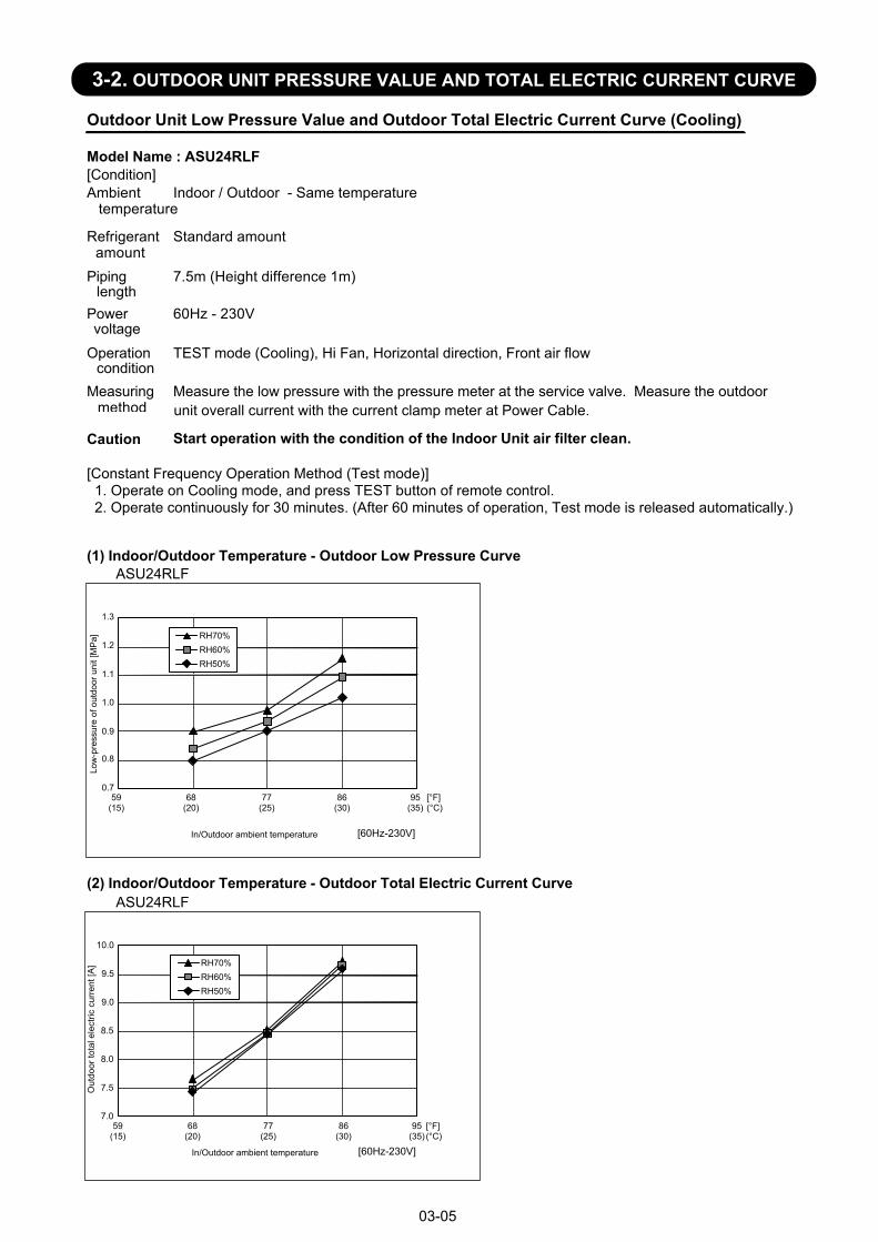
Outdoor Unit Low Pressure Value and Outdoor Total Electric Current Curve (Cooling)
Model Name : ASU24RLF[Condition]Ambient
temperatureIndoor / Outdoor - Same temperature
Refrigerantamount
Standard amount
Pipinglength
7.5m (Height difference 1m)
Powervoltage
60Hz - 230V
Operationcondition
TEST mode (Cooling), Hi Fan, Horizontal direction, Front air flow
Measuringmethod
Caution Start operation with the condition of the Indoor Unit air filter clean.
[Constant Frequency Operation Method (Test mode)] 1. Operate on Cooling mode, and press TEST button of remote control. 2. Operate continuously for 30 minutes. (After 60 minutes of operation, Test mode is released automatically.)
(1) Indoor/Outdoor Temperature - Outdoor Low Pressure CurveASU24RLF
(2) Indoor/Outdoor Temperature - Outdoor Total Electric Current CurveASU24RLF
Measure the low pressure with the pressure meter at the service valve. Measure the outdoorunit overall current with the current clamp meter at Power Cable.
03-05
0.7
0.8
0.9
1.0
1.1
1.2
59(15)
68(20)
77(25)
86(30)
95(35)
Low
-pre
ssur
e of
out
door
uni
t [M
Pa]
[60Hz-230V]
RH70%RH60%RH50%
In/Outdoor ambient temperature
7.0
7.5
8.0
8.5
9.0
9.5
10.0
Out
door
tota
l ele
ctric
cur
rent
[A]
1.3
[60Hz-230V]In/Outdoor ambient temperature
[°F](°C)
[°F](°C)
59(15)
68(20)
77(25)
86(30)
95(35)
RH70%RH60%RH50%
3-2. OUTDOOR UNIT PRESSURE VALUE AND TOTAL ELECTRIC CURRENT CURVE
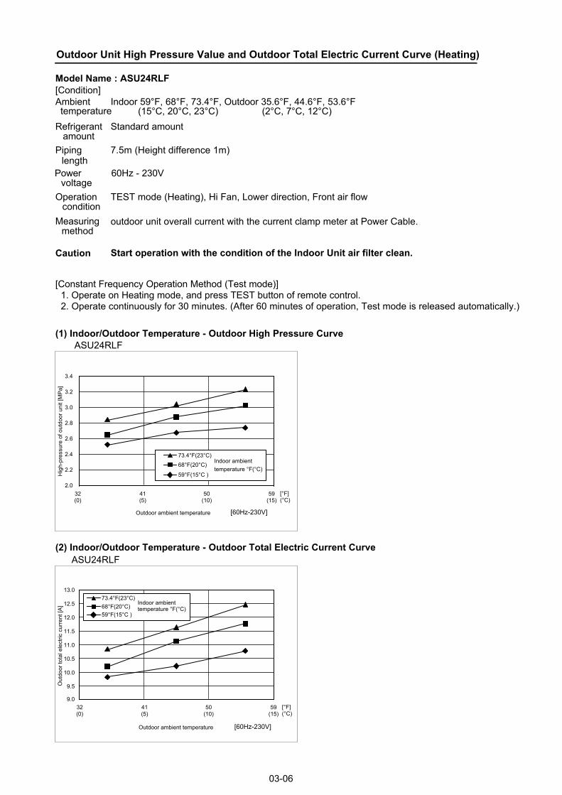
Outdoor Unit High Pressure Value and Outdoor Total Electric Current Curve (Heating)
Model Name : ASU24RLF[Condition]Ambient Indoor 59°F, 68°F, 73.4°F, Outdoor 35.6°F, 44.6°F, 53.6°F
(15°C, 20°C, 23°C) (2°C, 7°C, 12°C)Refrigerant
amountStandard amount
Piping 7.5m (Height difference 1m)
Powervoltage
60Hz - 230V
Operationcondition
TEST mode (Heating), Hi Fan, Lower direction, Front air flow
Measuringmethod
Caution Start operation with the condition of the Indoor Unit air filter clean.
[Constant Frequency Operation Method (Test mode)] 1. Operate on Heating mode, and press TEST button of remote control. 2. Operate continuously for 30 minutes. (After 60 minutes of operation, Test mode is released automatically.)
(1) Indoor/Outdoor Temperature - Outdoor High Pressure CurveASU24RLF
(2) Indoor/Outdoor Temperature - Outdoor Total Electric Current Curve
outdoor unit overall current with the current clamp meter at Power Cable.
length
03-06
2.0
2.2
2.4
2.6
2.8
3.0
3.2
3.4
32(0)
41(5)
50(10)
59(15)
Hig
h-pr
essu
re o
f out
door
uni
t [M
Pa]
[60Hz-230V]Outdoor ambient temperature
9.0
9.5
10.0
10.5
11.0
11.5
12.0
12.5
13.0
Out
door
tota
l ele
ctric
cur
rent
[A]
[°F](°C)
ASU24RLF
[60Hz-230V]Outdoor ambient temperature
32(0)
41(5)
50(10)
59(15)
[°F](°C)
73.4°F(23°C)
68°F(20°C)
59°F(15°C )
Indoor ambienttemperature °F(°C)
73.4°F(23°C) 68°F(20°C) 59°F(15°C )
Indoor ambienttemperature °F(°C)
temperature
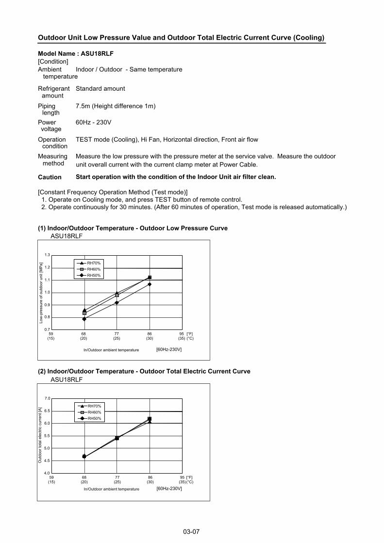
Outdoor Unit Low Pressure Value and Outdoor Total Electric Current Curve (Cooling)
Model Name : ASU18RLF[Condition]Ambient
temperatureIndoor / Outdoor - Same temperature
Refrigerantamount
Standard amount
Pipinglength
7.5m (Height difference 1m)
Powervoltage
60Hz - 230V
Operationcondition
TEST mode (Cooling), Hi Fan, Horizontal direction, Front air flow
Measuringmethod
Caution Start operation with the condition of the Indoor Unit air filter clean.
[Constant Frequency Operation Method (Test mode)] 1. Operate on Cooling mode, and press TEST button of remote control. 2. Operate continuously for 30 minutes. (After 60 minutes of operation, Test mode is released automatically.)
(1) Indoor/Outdoor Temperature - Outdoor Low Pressure CurveASU18RLF
(2) Indoor/Outdoor Temperature - Outdoor Total Electric Current CurveASU18RLF
Measure the low pressure with the pressure meter at the service valve. Measure the outdoorunit overall current with the current clamp meter at Power Cable.
03-07
0.7
0.8
0.9
1.0
1.1
1.2
59(15)
68(20)
77(25)
86(30)
95(35)
Low
-pre
ssur
e of
out
door
uni
t [M
Pa]
[60Hz-230V]
RH70%RH60%RH50%
In/Outdoor ambient temperature
4.0
4.5
5.0
5.5
6.0
6.5
7.0
Out
door
tota
l ele
ctric
cur
rent
[A]
1.3
[60Hz-230V]In/Outdoor ambient temperature
[°F](°C)
[°F](°C)
59(15)
68(20)
77(25)
86(30)
95(35)
RH70%RH60%RH50%
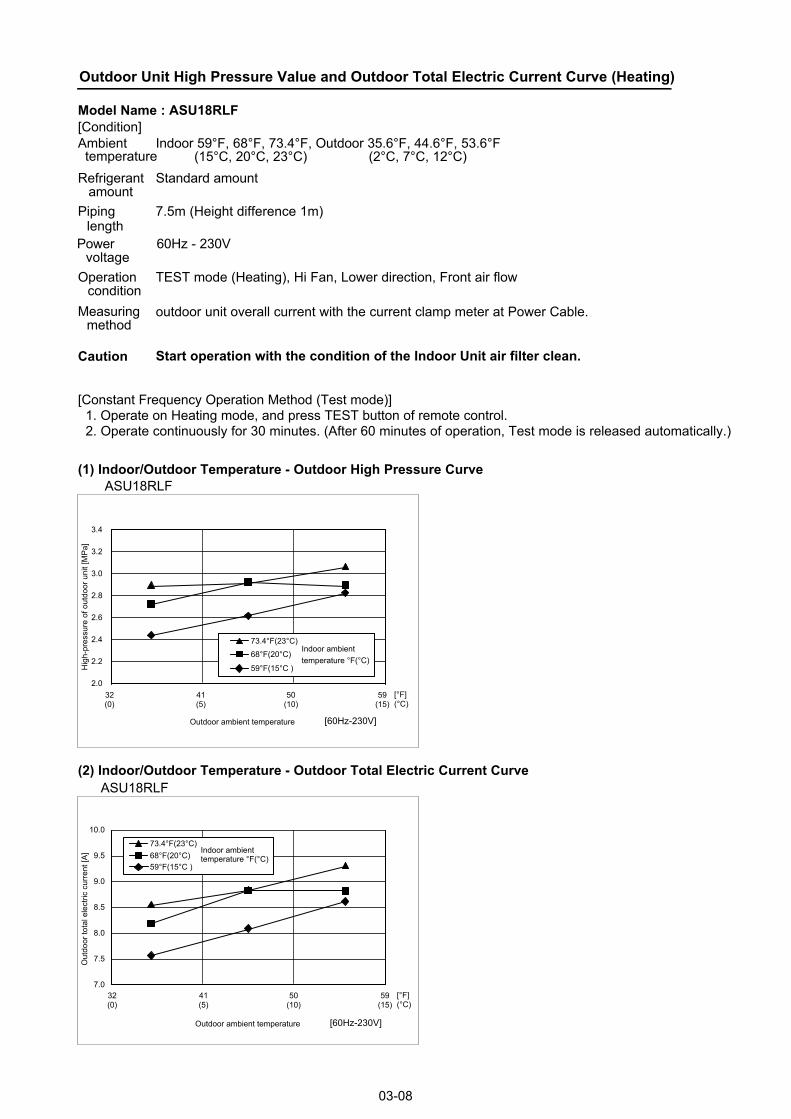
Outdoor Unit High Pressure Value and Outdoor Total Electric Current Curve (Heating)
Model Name : ASU18RLF[Condition]Ambient Indoor 59°F, 68°F, 73.4°F, Outdoor 35.6°F, 44.6°F, 53.6°F
(15°C, 20°C, 23°C) (2°C, 7°C, 12°C)Refrigerant
amountStandard amount
Piping 7.5m (Height difference 1m)
Powervoltage
60Hz - 230V
Operationcondition
TEST mode (Heating), Hi Fan, Lower direction, Front air flow
Measuringmethod
Caution Start operation with the condition of the Indoor Unit air filter clean.
[Constant Frequency Operation Method (Test mode)] 1. Operate on Heating mode, and press TEST button of remote control. 2. Operate continuously for 30 minutes. (After 60 minutes of operation, Test mode is released automatically.)
(1) Indoor/Outdoor Temperature - Outdoor High Pressure CurveASU18RLF
(2) Indoor/Outdoor Temperature - Outdoor Total Electric Current Curve
outdoor unit overall current with the current clamp meter at Power Cable.
length
03-08
2.0
2.2
2.4
2.6
2.8
3.0
3.2
3.4
32(0)
41(5)
50(10)
59(15)
Hig
h-pr
essu
re o
f out
door
uni
t [M
Pa]
[60Hz-230V]Outdoor ambient temperature
9.0
9.5
10.0
Out
door
tota
l ele
ctric
cur
rent
[A]
[°F](°C)
ASU18RLF
[60Hz-230V]Outdoor ambient temperature
32(0)
41(5)
50(10)
59(15)
[°F](°C)
73.4°F(23°C)
68°F(20°C)
59°F(15°C )
Indoor ambienttemperature °F(°C)
73.4°F(23°C) 68°F(20°C) 59°F(15°C )
Indoor ambienttemperature °F(°C)
temperature
8.5
8.0
7.5
7.0
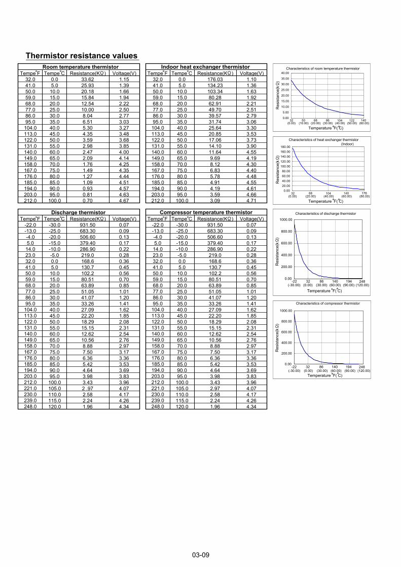
Characteristics of room temperature thermistor
0.00
5.00
10.00
15.00
20.00
25.00
30.00
35.00
40.00
(0.00) (10.00) (20.00) (30.00) (40.00) (50.00) (60.00)
Res
ista
nce(
k )
Temperature F( C)
32 50 68 86 104 122 140
0.0020.0040.0060.0080.00
100.00120.00140.00160.00180.00
(0.00) (20.00) (40.00) (60.00) (80.00)
Res
ista
nce(
k )
32 68 104 140 176
Temperature F( C)
Characteristics of heat exchanger thermistor (Indoor)
0.00
200.00
400.00
600.00
800.00
1000.00
(-30.00) (0.00) (30.00) (60.00) (90.00) (120.00)
Res
ista
nce(
k )
-22 32 86 140 194 248
Temperature F( C)
Characteristics of discharge thermistor
0.00
200.00
400.00
600.00
800.00
1000.00
(-30.00) (0.00) (30.00) (60.00) (90.00) (120.00)-22 32 86 140 194 248
Temperature F( C)
Characteristics of compressor thermistor
Res
ista
nce(
k )
Thermistor resistance values
03-09
32.041.050.059.068.077.086.095.0
104.0113.0122.0131.0140.0149.0158.0167.0176.0185.0194.0203.0212.0
0.05.0
10.015.020.025.030.035.040.045.050.055.060.065.070.075.080.085.090.095.0
100.0
33.6225.9320.1815.8412.5410.008.046.515.304.353.592.982.472.091.761.491.271.090.930.810.70
1.151.391.661.942.222.502.773.033.273.483.683.854.004.144.254.354.444.514.574.634.67
Room temperature thermistorVoltage(V)Resistance(K )Tempe F Tempe C
32.041.050.059.068.077.086.095.0
104.0113.0122.0131.0140.0149.0158.0167.0176.0185.0194.0203.0212.0
0.05.0
10.015.020.025.030.035.040.045.050.055.060.065.070.075.080.085.090.095.0
100.0
176.03134.23103.3480.2862.9149.7039.5731.7425.6420.8517.0614.1011.649.698.126.835.784.914.193.593.09
1.101.361.631.922.212.512.793.063.303.533.733.904.554.194.304.404.484.554.614.664.71
Indoor heat exchanger thermistorVoltage(V)Resistance(K )Tempe F Tempe C
-22.0-13.0-4.05.0
14.023.032.041.050.059.068.077.086.095.0
104.0113.0122.0131.0140.0149.0158.0167.0176.0185.0194.0203.0212.0221.0230.0239.0248.0
-30.0-25.0-20.0-15.0-10.0-5.00.05.0
10.015.020.025.030.035.040.045.050.055.060.065.070.075.080.085.090.095.0
100.0105.0110.0115.0120.0
931.50683.30506.60379.40286.90219.0168.6130.7102.280.5163.8951.0541.0733.2627.0922.2018.2915.1512.6210.568.887.506.365.424.643.983.432 .972.582.241.96
0.070.090.130.170.220.280.360.450.560.700.851.011.201.411.621.852.082.312.542.762.973.173.363.533.693.833.964.074.174.264.34
Discharge thermistorVoltage(V)Resistance(K )Tempe F Tempe C
-22.0-13.0-4.05.0
14.023.032.041.050.059.068.077.086.095.0
104.0113.0122.0131.0140.0149.0158.0167.0176.0185.0194.0203.0212.0221.0230.0239.0248.0
-30.0-25.0-20.0-15.0-10.0-5.00.05.0
10.015.020.025.030.035.040.045.050.055.060.065.070.075.080.085.090.095.0
100.0105.0110.0115.0120.0
931.50683.30506.60379.40286.90219.0168.6130.7102.280.5163.8951.0541.0733.2627.0922.2018.2915.1512.6210.568.887.506.365.424.643.983.432.972.582.241.96
0.070.090.130.170.220.280.360.450.560.700.851.011.201.411.621.852.082.312.542.762.973.173.363.533.693.833.964.074.174.264.34
Compressor temperature thermistorVoltage(V)Resistance(K )Tempe F Tempe C
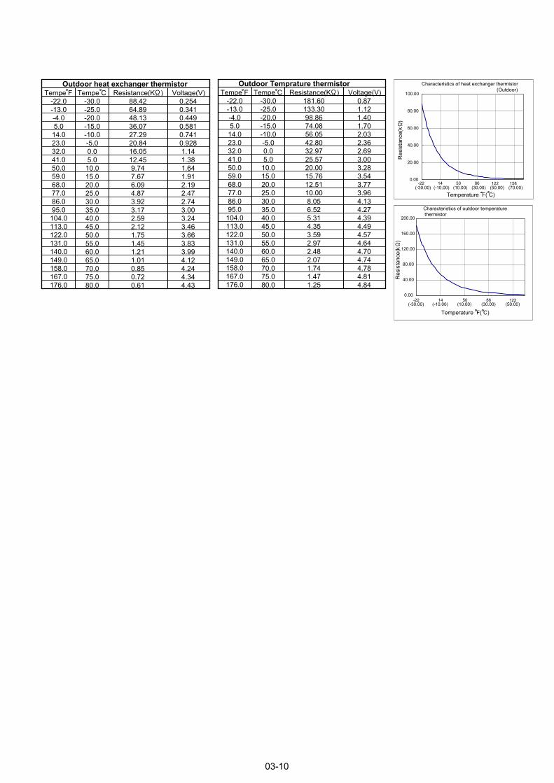
0.00
20.00
40.00
60.00
80.00
100.00
(-30.00) (-10.00) (10.00) (30.00) (50.00) (70.00)
Characteristics of heat exchanger thermistor (Outdoor)
Res
ista
nce(
k )
Temperature F( C)
-22 14 50 86 122 158
0.00
40.00
80.00
120.00
160.00
200.00
(-30.00) (-10.00) (10.00) (30.00) (50.00)
Characteristics of outdoor temperature thermistor
Res
ista
nce(
k )
Temperature F( C)
-22 14 50 86 122
03-10
-22.0-13.0-4.05.0
14.023.032.041.050.059.068.077.086.095.0
104.0113.0122.0131.0140.0149.0158.0167.0176.0
-30.0-25.0-20.0-15.0-10.0-5.00.05.0
10.015.020.025.030.035.040.045.050.055.060.065.070.075.080.0
88.4264.8948.1336.0727.2920.8416.0512.459.747.676.094.873.923.172.592.121.751.451.211.010.850.720.61
0.2540.3410.4490.5810.7410.9281.141.381.641.912.192.472.743.003.243.463.663.833.994.124.244.344.43
Outdoor heat exchanger thermistorVoltage(V)Resistance(K )Tempe F Tempe C
-22.0-13.0-4.05.0
14.023.032.041.050.059.068.077.086.095.0
104.0113.0122.0131.0140.0149.0158.0167.0176.0
-30.0-25.0-20.0-15.0-10.0-5.00.05.0
10.015.020.025.030.035.040.045.050.055.060.065.070.075.080.0
181.60133.3098.8674.0856.0542.8032.9725.5720.0015.7612.5110.008.056.525.314.353.592.972.482.071.741.471.25
0.871.121.401.702.032.362.693.003.283.543.773.964.134.274.394.494.574.644.704.744.784.814.84
Outdoor Temprature thermistorVoltage(V)Resistance(K )Tempe F Tempe C

1116,Suenaga,Takatsu-ku,Kawasaki 213-8502,Japan
Jan. 2011 Printed in Japan