Split type air conditioner Service Manual - Master … · Split type air conditioner Service Manual...
30
Split type air conditioner Service Manual MODEL: HSU09XCA HSU12XCA Haier Group For further improvement the information on the manual is subject to change without prior notice. NO.:
Transcript of Split type air conditioner Service Manual - Master … · Split type air conditioner Service Manual...

Split type air conditioner
Service Manual
MODEL: HSU09XCA HSU12XCA
Haier Group For further improvement the information on the manual is subject to change without prior notice.
NO.:

1
Content
1、 Product Code Illumination And Series introduction ----------------------------------------------- 2
2、 Features -------------------------------------------------------------------------------------------------------3
3、 Specifications ----------------------------------------------------------------------------------------------- 4
4、 Safty and Precaution ----------------------------------------------------------------------------------5
5、 Warning and Cautions ------------------------------------------------------------------------------------6
6、Net Dimention -------------------------------------------------------------------------------------------------8
7、Installation and Accessory Parts --------------------------------------------------------------------------9
8、Parts and Functions ----------------------------------------------------------------------------------------17
9、Abnormity Diagnose -----------------------------------------------------------------------------------------19
10、System Flow Chart -----------------------------------------------------------------------------------------20
11、Circuit diagram ---------------------------------------------------------------------------------------------21
12、Maintenance Service and Trouble Shooting --------------------------------------------------------22
13、Wiring Diagram -------------------------------------------------------------------------------------------24
14、Exploded View and Parts Lists ------------------------------------------------------------------------25
2
Product Code Illumination And Series Introduction
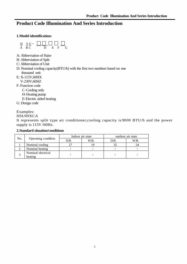
Product Code Illumination And Series Introduction 1.Model identification: H S U A B C D E F G A: Abbreviation of Haier B: Abbreviation of Split C: Abbreviation of Unit D: Nominal cooling capacity(BTU/h) with the first two numbers based on one thousand unit E: X-115V,60HX V-230V,60HZ F: Function code C-Cooling only H-Heating pump E-Electric aided heating G: Design code Examples: HSU09XCA It represents split type air conditioner,cooling capacity is 9000 BTU/h and the power supply is 115V /60Hz.
2.Standard situation/conditions
Indoor air state outdoor air state No. Operating condition
D.B.℃ W.B.℃ D.B.℃ W.B.℃ 1 Nominal cooling 27 19 35 24 2 Nominal heating / / / /
3 Nominal electrical heating / / / /

3
Features
Features Features:
1.Easy Installation
2.Zone Control
3.Direct Ductless Air Flow Distribution, Energy Efficient without Duct Loss
4.Ultra-Quiet Operation
5.Sleek Appearance
6.Auto Restart
7.24 Hour On/Off Timer
8.Sleep Function
9.Dehumidification Function
10.3 Cool Settings, 3 Fan Settings

4
Specifications
Specifications:
Item UNIT HSU09XCA HSU12XCA Cooling capacity BTU/h 9000 12000 Heating capacity BTU/h / / Power supply 1PH/115V/60Hz 1PH/220~230V/50Hz
Power input W 900 1280 Running current A 8.2 11.1 Cooling SEER BTU/(hW) 10.0 10.0 Power input W / / Running current A / / Heating COP BTU/(hW) / / Indoor side dB(A) 46 46
Sound Level Outdoor side dB(A) 54 54 Height mm 795 795 Width mm 182 182 Case(indoor) Depth mm 265 265 Height mm 780 780 Width mm 250 250 Case(outdoor) Depth mm 650 650 Height mm 860 860 Width mm 270 270 Packaging
dimensions(indoor) Depth mm 330 330 Height mm 1001 1001 Width mm 340 340 Packaging
dimensions(outdor) Depth mm 609 609 Net kg Indoor:7.2/Outdoor:32 Indoor:7.2/Outdoor:36 Weight Gross kg Indoor:10.2/Outdoor:38 Indoor:10.2/Outdoor:42 Type Rotate Rotate Model 2P14S126B1M 2P19S3R126B1E Running cap. for comp. μF 40uf/250VAC 45uf/250VAC Compressor
Starting method PSC PSC Heating side MPa 380 380 Pressure Cooling side MPa 170 170 Model R22 R22 Refrigerant Charge kg 0.75 1.2
indoor unit Acentric fan Acentric fan Type
outdoorunit Axial fan Axial fan indoor unit r/min 1250±30/1100±30/950±30 1300±30/1150±30/950±30
Fan Fan speed
outdoorunit r/min 760±50 820±50 Air volume m3/hr 500 550 Moisture removal m3/hr 1.2x10⁻³ 1.2x10⁻³ Exchanging pipe type/ diameter mm Evaporator:ф7
condenser:ф9.52 Evaporator:ф7
condenser:ф9.52 Fin material Hydrophile aluminum foil Hydrophile aluminum foil

5
Safty and Precaution
Safty and Precaution

6
Warning and Cautions
Warning and Cautions

7
Warning and Cautions
Warning and Cautions

8
Net Dimention
Net Dimention
W
Indoor Outdoor Model L W H L W H
HSU09XCA 795 182 265 780 250 650 HSU12XCA 795 182 265 780 250 650
L L
H
H
9
Installation and Accessory Parts
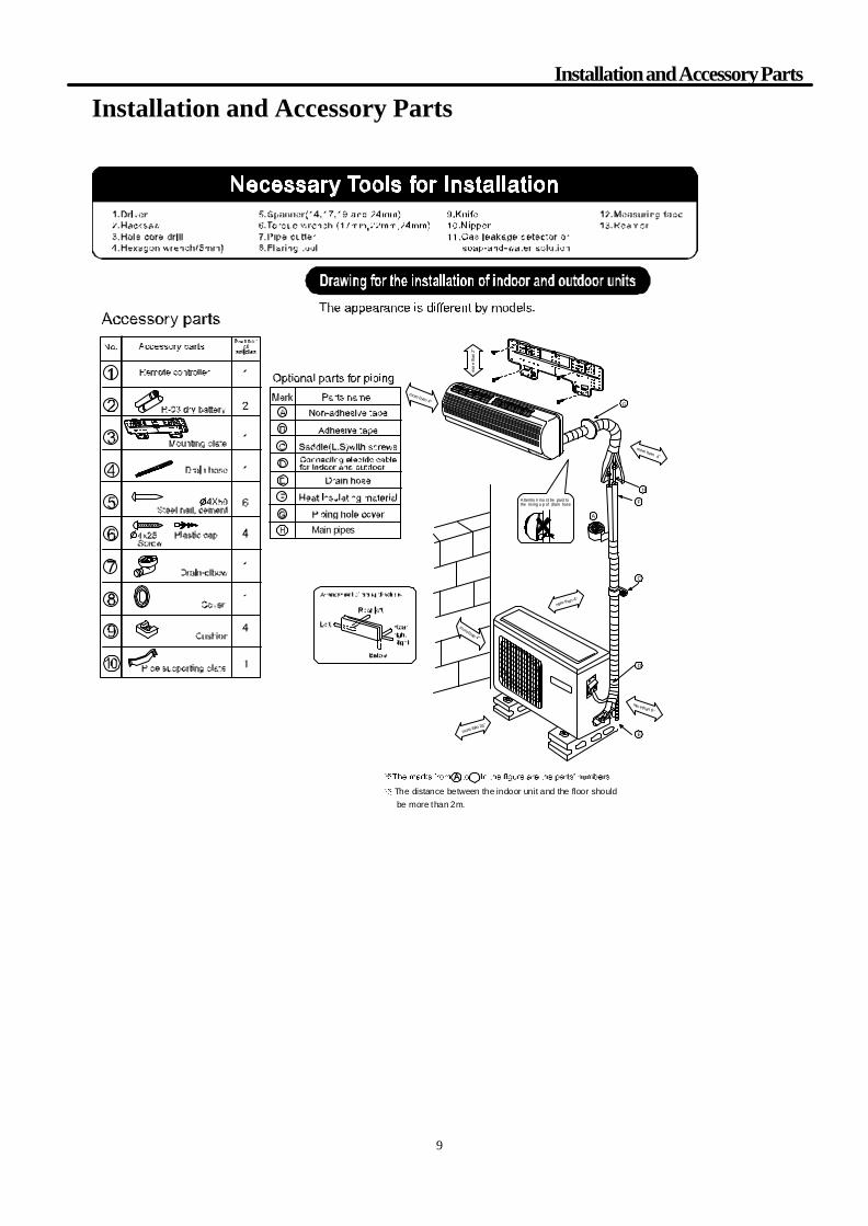
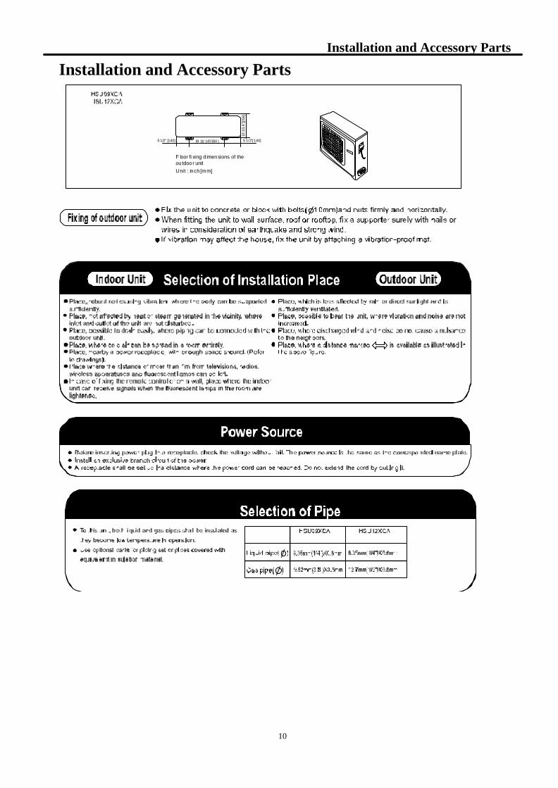
Installation and Accessory Parts
morethan 4"
more than 26"
mor ethan 6"
more than 4"
Attentio n mu st be paid tothe rising u p of drain hose
mor
eth
an2"
more than 4"
A
G
D
E
C
more than 4"
F
H
H Main pipes
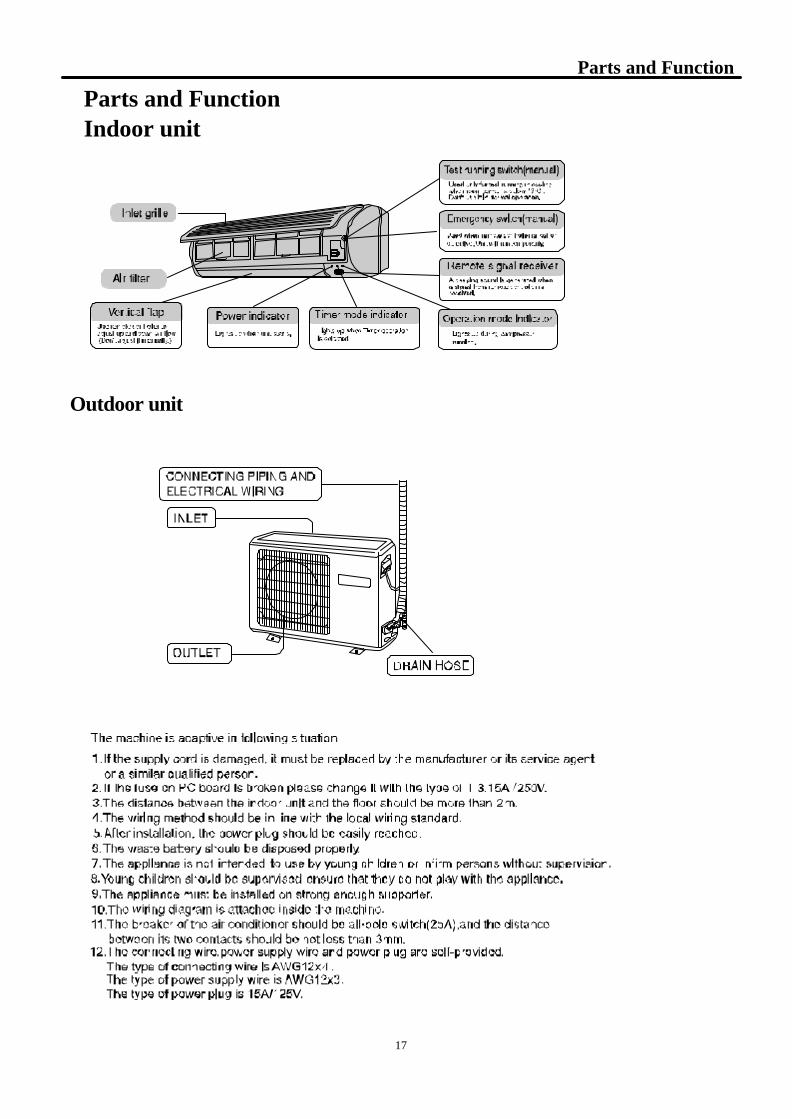
The distance between the indoor unit and the floor should be more than 2m.
10
Installation and Accessory Parts
Installation and Accessory Parts
F loor fi xing d imensions of theoutdoor unitUnit : inch [mm]
5 1/2" [140]
10 1
/16"
[256
]
19 11/ 16"[500 ] 5 1/2"[140]

11
Installation and Accessory Parts
Installation and Accessory Parts
A
B
(5.7") (2.36")
( inch)( inch)
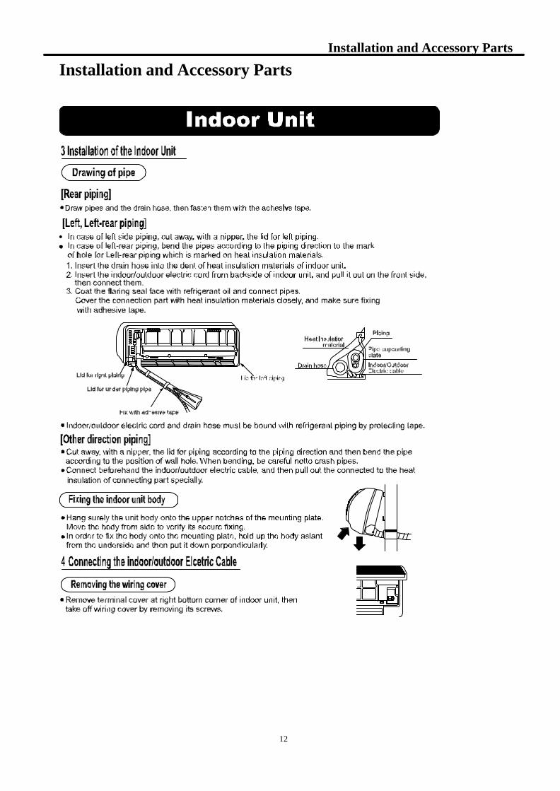
Hanging
Pass the threadthrough this
12
Installation and Accessory Parts
Installation and Accessory Parts

13
Installation and Accessory Parts
Installation and Accessory Parts
c
for easy connection later
Position using
total
HSU09XCAHSU12XCA
14
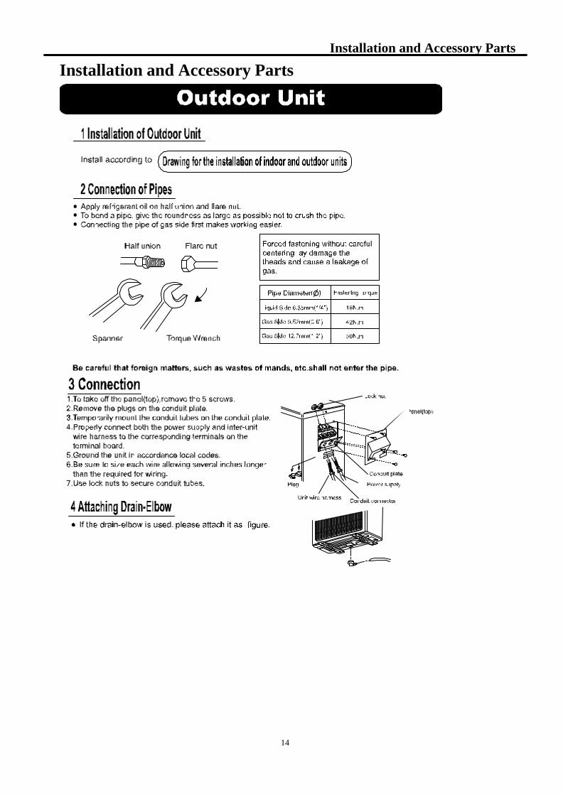
Installation and Accessory Parts
Installation and Accessory Parts
U
5
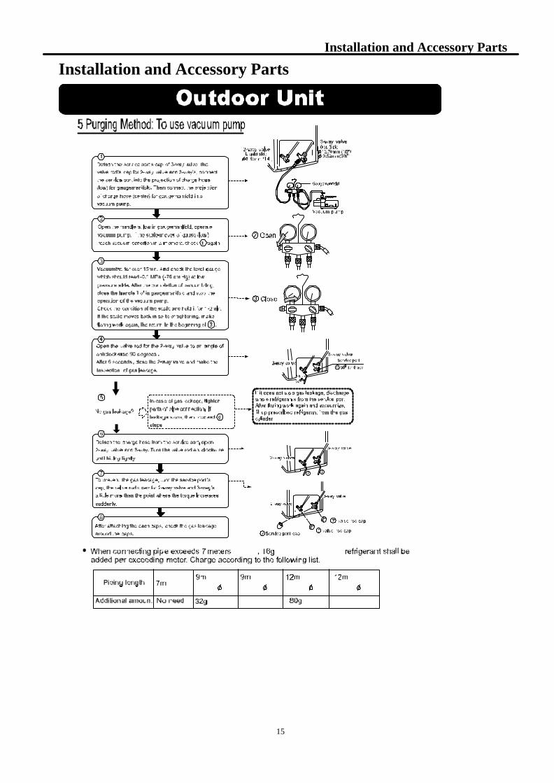
15
Installation and Accessory Parts
Installation and Accessory Parts

16
Installation and Accessory Parts
Installation and Accessory Parts
17
Parts and Function
Parts and Function Indoor unit
Outdoor unit
18
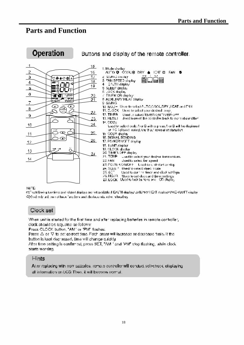
Parts and Function
Parts and Function
19
Abnormity Diagnose
Abnormity Diagnose
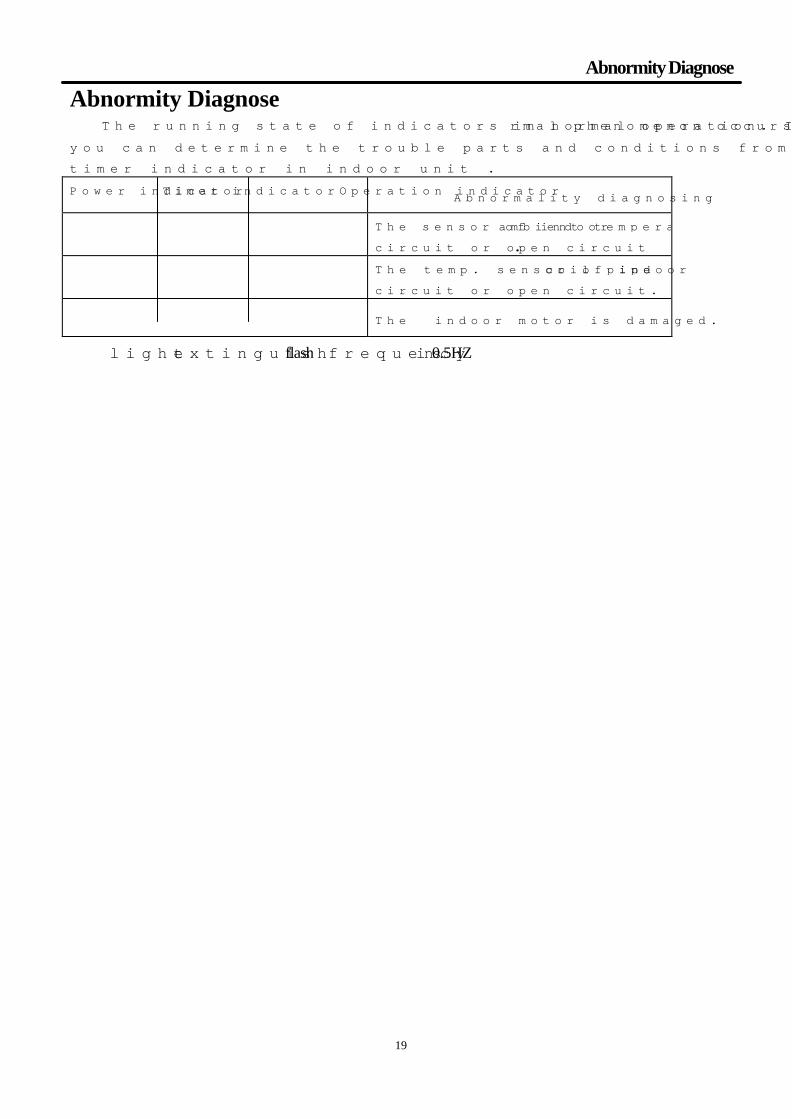
The running state of indicators in normal operation. If any abnormal phenomenon occurs in PC board,
you can determine the trouble parts and conditions from the power indicator, operation indicator and
timer indicator in indoor unit . Power indicator Timer indicatorOperation indicator
Abnormality diagnosing
★ ■ ■ The sensor of indoor ambient temperature is short circuit or open circuit.
★ □ □ The temp. sensor of indoor coil pipe is short circuit or open circuit.
★ ■ □ The indoor motor is damaged.
□light ■extinguish,★flash,frequency is 0.5HZ。

20
System Flow Chart
System Flow Chart
Indoor heat exchanger
Outdoor heat exchanger
Compressor
Capacillary tube
Cooling

21
Circuit Diagram
Circuit Diagram
1 2 3 4 5 6 7 8
A
B
C
D
87654321
D
C
B
A
+5
R8510
C16 104
R9
62K
R56 3.3K+5 IC8
LM358
C14100UF/16V
R55 2K
R2 5.1K
R3 10K
+5
DQ19012
R395.1K
VDD+12
JK1JQ1aP-12V
C29103
R2710K
+5
DQ69014
R1110K
+12
R2610K
R5210K
IC7LM358
+12
R1310K
DQ49014
DQ52N5551
R515.1K
R10 5.1K
R345.1K
R331K
C21104
+5
+5R60
10K
C13
102/1KV
R57
62K/3W
R16 1K
R171K
+5L1
101C27
4.7UF/16V
L2 331R20
20K
R1910K
C28
4.7UF/16VL3 331
R18 20K
R2110K
C25104
+5
R30 10M
+5
+5
D7
1N4148
R2810K
C244.7UF/16V
R291K
+5
C23
102
R54 1K
+5
C12
100UF/16V
R381M D6
1N4148
R3251K
R153K/2W
+5
C7104
C8220UF/16V
Vin1
GN
D2
Vout 37805
C18
470UF/100V
C17
470UF/100V
C311000UF/25V
D1UF106
D5MUR860
C5
47UF/25V
R110
PC1TLP521-1
C4
0.1UF/50V
D81N4148
D41N4007
D2
P6KE200
T1
C3100UF/400V
B1KBJ406 NTC
5D-15
C20.1UF/275VF1
T3.15A 250VAC
P771
P762
P753
P744
P735
P726
P717
P708
P079
P0610
P0511
P0412
P0313
P0214
P0115
P0016
TEST17
RESET18
XIN19
XOUT20
VSS21 VAREF 22P60 23P6124P62 25P63 26P64 27P6528P66 29P67 30P10 31
P11 32P12 33P13 34P14 35P15 36P16 37P17 38P20 39P21 40P22 41VCC 42
IC1TMP87PH46N
EZ1
C1
0.1UF/275V
C22 104
A11
A22
A33
A44
A55
A66
A77
Q1 16
Q2 15
Q3 14
Q4 13
Q5 12
Q611
Q7 10
GND8 VCC 9
IC3ULN2003A
+12
+12
C26104
R5 100
BUZ
PS144DP02B-T
R41K
+12
XT2P
R3510K
+5
R532K
C19103
C20104
R4410K
+5 R4110K
+5
C11
104
C15104
+5
DQ29014
R40 5.1K
+5R46 10K
DQ39014
R455.1K+5
C10330UF/50V
L4331
Z11N5819
+12
+12
C9104
VDD
R3720K
C6104
C34103
C35104
C36100UF/16V
C30Y2 2.2nF 250VAC
R5010K
C33104
8MHZ
103N
KB2271447
TOP226Y
T600D
C
D
S
M1
CN6
TL431
IC5
CA1
CN5
CN8
OSC
IC4
CN7
CN2
DL1
CN3
JK2G4A-1A-E(60GW)
+12
LX1
1
2
4
3
16
15
14
CN9
R22 220
R23 220
R24 220
R25 22013
CN101
R10110K R102
300
L101
L102
C101
L103
REV
N
13
2
SW1
JTP 1236A
+5
R1410K
C T
0057W
B2 SINB60
R61K
D3
N4148
C32470UF
R7
560
VR1200
+5
J24J
J J19
R42
10K
R43
10K
+5
DQ9
9014
R47
5.1K
DQ8
9014
R48
R5.1K
DQ7
9014
R49
5.1K
11
+12V
12
7
6
10
8
38
39
4140
37
36
35
31
18
L
+12V
CN1
C37104
R59
10K
SW2
JSS 1271
R58 2K+5
B
A A-B
Room Temp.
Piping Temp.
²½½øµç»ú
Outdoor fan
4-Way Valve
Compressor
DC12V FU li zi
LCD Board
LED Board
Remote out
Indoor Fan
Cop. run relay
Fan feedback
Remote Out
Outdoor Fan
4-Way Valve
Run Light
Timer Light
Power light
Piping Temp Room Temp
Step Motor
COMP
Buzzer outPG/out
Rem SinglePG/IN
Step MotorStep MotorStep Motor
Remote in1 / 1 2 5
SW1SCLSDA
HSU-18VHAµÈTYPENUM.
Date 2004-5-1
񅙒
ÉóºË
J38
A01
A12
A23
GND4 SDA 5
SCL 6
W P 7
VCC 8
24C01AR31
10K
+5
+5R64
10K
+5
R1210K
+5
/JQ1aP-12C(70GW)
R65 100/1w
C43
Y2 2.2nF 250VACC42
Y2 2.2nF 250VAC
R6247K
D9
IN4757A
C380.47UF/50V
DQ109014
4
2
3 5
1LM2575-12
IC6C39104
R61100K
R6324
D101N4751A
JK4D12
1N4007
D11
1N4007
D13
1N4007
JK5
JK3
+12V
+12V
CN12
CN10
CN11
22
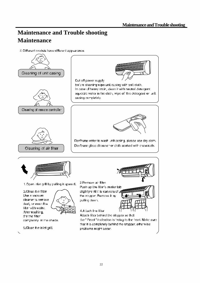
Maintenance and Trouble shooting
Maintenance and Trouble shooting Maintenance
23
Maintenance and Trouble shooting
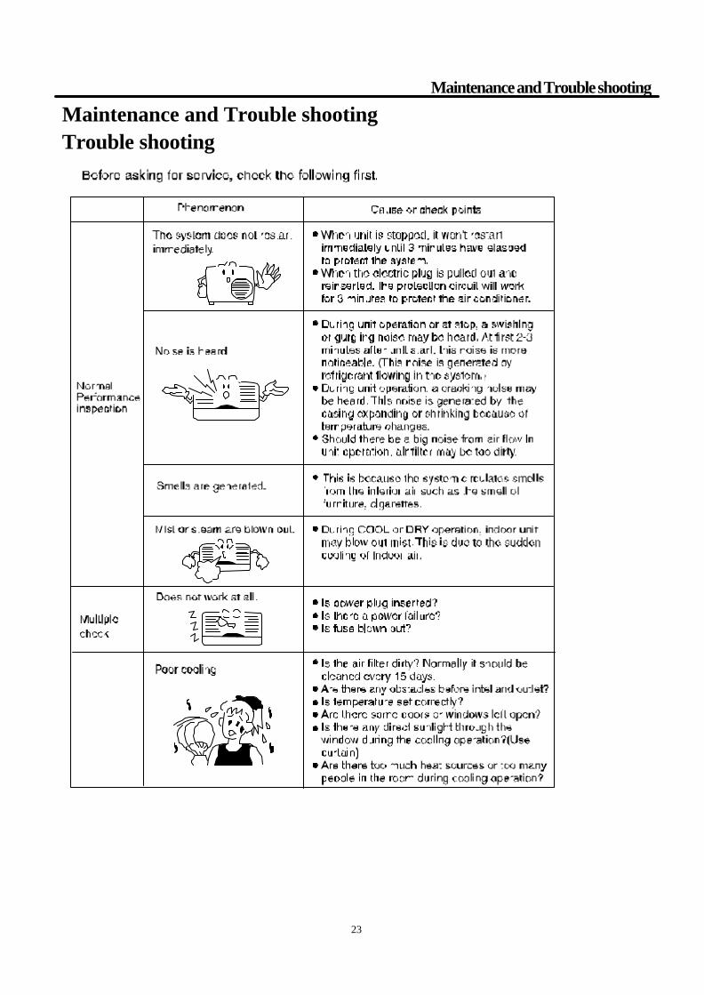
Maintenance and Trouble shooting Trouble shooting

24
Wiring Diagram
Wiring Diagram Indoor
Display
MotorFan
Receiver
2.COOLING ONLY No dotted line.
WIRING DIAGRAM OF SPLIT UNIT,INDOOR
Transformer
1.HEAT PUMP have dotted line(signed @)
GR:GRAYBR:BROWNW:WHITER:REDB:BLACK
CN3
FUSE
CN2
BLBL
CN9
*
CN1
*
RR
Note:
S901
3
WB
1 2
* *GR R BR
54
@
CN6
@
CN5
MotorLouver
CN7
CTCN8
Manual
Room Temp.Thermistor
Piping Temp.ThermistorSwitch
SignalC
N16 Intergrated
Controller
3.You can choose the part in dashed
1
frame or not.
0010544565
Outdoor:
NOTE:
(marked with @) on simple cool type.
from BR (marked with @@)on terminalNo dotted line wire is connected
block to 3.
2.There are no dotted lines
1.See above for wiring of
YELLOW/GREEN
RED
WHITE
BROWN
BLACK
BLUE
CAPACITOR
BL:
cool-warm type.
Y/G:
R:W:
BR:
B:
W(R)
B(C)R(S)
TERMINALCOMPRESSOR
FAN
MOTOR
5 6 7
R
RCAPACITOR
W B
COMP
R CS-INGBL
@BL
@ REVERS
WVALVE
BLOCK,INDOORTERMINAL 1 2
BLOCK,OUTDOOR
1TERMINAL
2
53 4
43
B
NL
WIRING DIAGRAM OF SPLIT UNIT,OUTDOOR
0010544566
BR
@ @
@@
B W
BR

26
2728
2324
2510
209 17 16
15
18
5
19
13
14
11
21
22
12
8
4
2
6
37
DIAGRAM NO: AC-04-007a

HSU12XCA (INDOOR)
Description Fig #AC-0344-01 BEARING 14AC-0595-04 BLOCK-TERMINAL 7AC-0800-46 BOX 27AC-1470-16 CASE-REAR ASSY 11AC-1870-01 CONTROL-ASSY 1AC-1950-59 COVER 26AC-1950-60 COVER 28AC-1950-64 COVER-MOTOR 4AC-2650-28 EVAPORATOR 19AC-2750-24 FAN AC-2750-24AC-2750-24 FAN 13AC-2800-15 FILTER-AIR 20AC-2850-06 FLAP-BOTTOM 23AC-2850-05 FLAP-TOP 17AC-3150-15 GRILL - FRONT 10AC-3570-03 HOSE -DRAIN 18AC-3570-04 HOSE -DRAIN 25AC-4550-34 MOTOR AC-4550-34AC-4550-34 MOTOR 12AC-4550-37 MOTOR-SWING AC-4550-37AC-4550-37 MOTOR-SWING 16AC-5150-18 PAN 15AC-5200-123 PANEL -FRONT 9AC-5210-14 PCB AC-5210-14AC-5210-14 PCB 2AC-5300-52 PLATE-MOUNTING 21AC-5620-11 REMOTE 24AC-6250-02 SENSOR 5AC-7000-16 SUPPORT-PIPING 22AC-7550-04 TRANSFORMER 6
Part Number

910
11
12
13141516
17
18
19
20
21
22
23
24
25
26
27
29
1
2
3
430
5
28
6 7
8
DIAGRAM NO: AC-04-007b

HSU12XCA (OUTDOOR)
Description Fig #AC-0010-34 ACCESSORIES - COMPRESSOR ELECT 16AC-0668-18 BOARD-MOTOR 5AC-0800-47 BOX-ELECTRIC 24AC-1400-10 CAPACITOR - COMPRESSOR AC-1400-10AC-1400-10 CAPACITOR - COMPRESSOR 23AC-1400-01 CAPACITOR - FAN MOTOR AC-1400-01AC-1470-17 CASE 2AC-1750-41 COMPRESSOR AC-1750-41AC-1750-41 COMPRESSOR 18AC-1800-26 CONDENSER-ASSY. 6AC-1900-11 CORD-WIRE 25AC-1950-61 COVER-SERVICE 28AC-1950-62 COVER-TERMINAL 15AC-1950-63 COVER-TERMINAL 22AC-2015-51 CUSHION 26AC-2750-26 FAN-AXIAL AC-2750-26AC-2750-26 FAN-AXIAL 4AC-3150-16 GRILL - FRONT 1AC-3150-14 GRILL - REAR 7AC-4550-36 MOTOR AC-4550-36AC-4550-36 MOTOR 30AC-4720-20 NUT 14AC-4720-22 NUT 3AC-4720-03 NUT - COMPRESSOR 17AC-5200-122 PANEL-TOP 8AC-5255-103 PIPE-DISCHARGE 9AC-5255-104 PIPE-SUCTION 21AC-5300-50 PLATE-BOTTOM ASSY. 29AC-5300-51 PLATE-SEPERATING 27AC-6150-29 SCREW 11AC-7750-38 TUBE-CAPILLARY ASSY. 10AC-7800-02 VALVE -STOP 12AC-7800-01 VALVE -STOP 13AC-7950-02 WASHER 19
Part Number

31
S incere Forever
H a ie r G ro u pT e l:8 6 -5 3 2 -8 9 3 8 3 5 6
W e b S ite :h ttp ://w w w .h a ie r.c o m