Spiral Bevel Gears with Optimised Tooth-end …...Spiral bevel gears with complementary tooth-end...
10
Procedia Engineering 69 (2014) 383 – 392 Available online at www.sciencedirect.com 1877-7058 © 2014 The Authors. Published by Elsevier Ltd. Open access under CC BY-NC-ND license. Selection and peer-review under responsibility of DAAAM International Vienna doi:10.1016/j.proeng.2014.03.003 ScienceDirect 24th DAAAM International Symposium on Intelligent Manufacturing and Automation, 2013 Spiral Bevel Gears with Optimised Tooth-End Geometry † Karlis Paulins, Arturs Irbe, Toms Torims* Riga Technical University, Faculty of Transport and Mechanical Engineering, Ezermalas Str. 6k-105, LV – 1006, Riga, Latvia Abstract Industrially-manufactured, spiral bevel gears with complementary tooth-end surfaces as a rule have reduced tooth thickness and subsequently reduced strength at the tooth ends. The weakened tooth ends of octoid gearing are generally produced by machining, inevitably resulting in a certain lengthwise dimensional discrepancy and slight profile difference. This in turn very often leads to systematic breakage of teeth. Serious, systematic damage occurs irrespective of the transmission tightness of the outer or inner tooth ends. Gear manufacturers currently use several solutions to avoid such breakages, including artificial inclination near to the teeth or deliberately reducing the back or outer cone angle and increasing the front or root cone angle. This paper outlines an improved design of gear blanks, with optimised tooth ends. Our research concluded that it is possible to optimise rectangular-generated, spiral bevel pinion/gear pairs with constant tooth height and a common pitch cone apex. We can successfully achieve this through recalculation of the gear blanks, without any changes in the flank geometry or tooth-cutting process. Thus the gear pair with optimised tooth ends can be cut without interference to the customary tooth-cutting process. To prove the concept, an example of the recalculation is provided. These improvements result in increased tooth strength, simplification of the gear blank geometry and more suitable geometry for modern machining, as well as a smaller outer diameter of the gear. Keywords: spiral bevel gears; tooth geometry; gear transmission; optimisation * Corresponding author. Tel.: +371-20-200-195. E-mail address: [email protected] © 2014 The Authors. Published by Elsevier Ltd. Open access under CC BY-NC-ND license. Selection and peer-review under responsibility of DAAAM International Vienna
Transcript of Spiral Bevel Gears with Optimised Tooth-end …...Spiral bevel gears with complementary tooth-end...
Procedia Engineering 69 ( 2014 ) 383 – 392
Available online at www.sciencedirect.com
1877-7058 © 2014 The Authors. Published by Elsevier Ltd. Open access under CC BY-NC-ND license.Selection and peer-review under responsibility of DAAAM International Viennadoi: 10.1016/j.proeng.2014.03.003
ScienceDirect
24th DAAAM International Symposium on Intelligent Manufacturing and Automation, 2013
Spiral Bevel Gears with Optimised Tooth-End Geometry †Karlis Paulins, Arturs Irbe, Toms Torims*
Riga Technical University, Faculty of Transport and Mechanical Engineering, Ezermalas Str. 6k-105, LV – 1006, Riga, Latvia
Abstract
Industrially-manufactured, spiral bevel gears with complementary tooth-end surfaces as a rule have reduced tooth thickness and subsequently reduced strength at the tooth ends. The weakened tooth ends of octoid gearing are generally produced by machining, inevitably resulting in a certain lengthwise dimensional discrepancy and slight profile difference. This in turn very often leads to systematic breakage of teeth. Serious, systematic damage occurs irrespective of the transmission tightness of the outer or inner tooth ends.
Gear manufacturers currently use several solutions to avoid such breakages, including artificial inclination near to the teeth or deliberately reducing the back or outer cone angle and increasing the front or root cone angle.
This paper outlines an improved design of gear blanks, with optimised tooth ends. Our research concluded that it is possible to optimise rectangular-generated, spiral bevel pinion/gear pairs with constant tooth height and a common pitch cone apex. We can successfully achieve this through recalculation of the gear blanks, without any changes in the flank geometry or tooth-cutting process. Thus the gear pair with optimised tooth ends can be cut without interference to the customary tooth-cutting process. To prove the concept, an example of the recalculation is provided. These improvements result in increased tooth strength, simplification of the gear blank geometry and more suitable geometry for modern machining, as well as a smaller outer diameter of the gear. © 2014 The Authors. Published by Elsevier Ltd. Selection and peer-review under responsibility of DAAAM International Vienna.
Keywords: spiral bevel gears; tooth geometry; gear transmission; optimisation
* Corresponding author. Tel.: +371-20-200-195. E-mail address: [email protected]
© 2014 The Authors. Published by Elsevier Ltd. Open access under CC BY-NC-ND license.Selection and peer-review under responsibility of DAAAM International Vienna

384 Karlis Paulins et al. / Procedia Engineering 69 ( 2014 ) 383 – 392
1. Tooth-end problems
Bevel-gear tooth ends are usually limited by complementary cones. In theory, the conical tooth-end surfaces of mating gears coincide with each other. This tooth-end format is dictated by simple, mutual face-width limitation, without any geometric reasoning behind it (e.g. for one of the mating gears). The said coincidence of mating theoretical tooth ends is sometimes used for the practical purpose of adjusting a bevel gear pair. In this case, the back cone is used for the axial setting of the gear blank on certain tooth-cutting machines.
From the point of view of tooth strength, the straight tooth-end complementary cones would be desirable for this type of tooth: straight teeth have maximal thickness in the direction of normal forces on either side of the tooth. From the technological standpoint, complementary cones provide the minimum stroke length in straight-tooth shaping. The back cone provides a basis for defining the thickness of the teeth.
Spiral teeth function under different conditions. Spiral bevel gears with complementary tooth-end surfaces have reduced tooth thickness and correspondingly reduced strength at the tooth ends.
With commonly used octoid gearing, the weakened tooth ends are renewed by machining, with appropriate lengthwise mismatch and a slight profile difference. The middle part of the profile and length of the teeth play an almost equal role in the engagement process.
In the case of Novikov-Wildhaber (NW) gearing, the roles of the profile and length tend to coincide: the profiles of mating teeth have a considerably different curvature, but there is practically no difference in lengthwise curvature [1, 2]. The engagement of the teeth occurs lengthwise. NW gearing contact patterns spread like parallel belts over the full length of the teeth. (Fig. 1a)
Nomenclature
Ai1 inner mounting distance from the pitch cone apex Ai2 inner mounting distance of the gear Bae1,2 coordinates of the outer face circles Bce1min inner end elongation of the gear teeth dae1 outer diameter of the pinion dai1 inner face circle diameter of the pinion dai2 inner face circle diameter of the gear de2 outside diameter of the gear f1min minimum width of the outer cylinder ring of the pinion f2min minimum width of the inner plane ring of the gear Fe axial component of the gearing forces at the outer end Fi radial component of the gearing forces at the outer end ha uncorrected addendum ha addendum (without displacement) i pinion / gear transmission ratio i1 pinion / virtual plane gear transmission ratio i2 gear / virtual plane gear transmission ratio kb width factor kb face width factor NW Novikov-Wildhaber gearing rt rounding radius xm profile shift α tooth pressure angle βe,βi spiral angles ψ tooth-end inclination angle ф diameter

385 Karlis Paulins et al. / Procedia Engineering 69 ( 2014 ) 383 – 392
Fig. 1. Side view of spiral teeth with belt-type, NW contact patterns (a, b and c) and an oval octoid gearing contact pattern (d).
Long-term (over 30 years) research in field of the NW bevel gearing design and technology, together with the widespread practical use of NW bevel gears in various machines, has proved that NW bevel gearing is sensitive to elastic deformations and therefore useable only in very tight transmissions [3]. Independently of the transmission tightness, the outer tooth ends—loaded on the concave side—and inner tooth ends—loaded on the convex side—frequently or systematically break, as shown in Fig.1a.
The problem of tooth-end breakage in NW gearing was solved in two alternative ways. The first solution was based on the customary tooth crown form and involved localization of the bearing by flank
relief (inclination) near the tooth end (Fig.1b). However, this complicated the tooth-cutting process [4, 5]. It was discovered that complementary cones as tooth-end surfaces are not ideal for NW gearing. The second,
more simple and universal solution was to abandon complementary cones [6, 7], reducing the back or outer cone angle and increasing the front or root cone angle, without changing the tooth crown width on the pitch cone (Fig. 1c). Thus the tooth-end thickness was increased in the direction of the forces acting in the gear’s axial section. These forces represent the vector sum of the axial and radial components of the gearing forces Fe at the outer end and Fi, at the root end.

386 Karlis Paulins et al. / Procedia Engineering 69 ( 2014 ) 383 – 392
Such an inclination of the tooth-end surface ensures fast and maximal tooth thickness behind the tooth-end edge, in the direction of the axial-radial forces.
The tooth-end inclination angles ψ depend on the tooth pressure angle α and spiral angles βe and βi:
ψ = arc tan (cot α*.sin β) (1)
The sum of the outer and inner inclination angles of the NW spiral bevel gears studied, with α = 27, βe = 45˚…50˚ and βi = 20˚…25˚, was not less than 90˚. This means that instead of the customary parallel tooth ends of octoid teeth, NW gearing needs approximately perpendicular tooth ends. Gears with a pitch cone of more than 45˚ require an inverted, negative back cone. Pinions needed an inverted, positive front cone. At a pitch-cone angle of about 40˚, the inner tooth-end faces become plane and outer tooth-end faces cylindrical. The strengthening of tooth ends in this case coincides with the geometrical simplification of the gear blank.
2. Optimised tooth-end surfaces for octoid gearing
The plane as the inner tooth-end face of octoid gearing is used mostly for pinion shafts. The cylinder as the outer-tooth end face is used, albeit very rarely, for very flat ring gears. It occurs mainly on the grounds of design, having no theoretical connection with gearing geometry. Only the plane, inner-tooth face is computationally related to gearing geometry in some of the existing calculation methods.
The customary outer and inner chamfers of the tooth ends are not included in the gearing calculation, although the chamfers may clip a considerable part of the tooth height and may indefinitely change the dimensions. After the customary chamfering, it is impossible to conduct a simple check of the main dimensions of the gear blank. Including chamfers in main-gear geometry ensured by present-day CNC technology [10, 11].
Due to the positive experience in the field of various gearings, the plane and cylindrical tooth end faces were fully transferred to octoid gearing, given that odd corners of the addendum can break in the event of unexpected contact pattern deviation or after certain wear on the teeth or bearing, whereas the extended root offers additional reinforcement of the teeth. Geometric analysis of various octoid gear transmissions and a comparison with positively solved NW gearings has led to the conclusion that the expanded addendum corners fall outside the oval contact pattern (Fig.1d) and may be regarded as odd, if we take only the theoretical tooth-end design into account. The corners can be clipped by plane or cylinder, but the clipping should not be deeper or farther from the face-cone edges than the uncorrected addendum [8, 9] ha. Experience in the field of NW gearing has made it possible to transfer new solutions to strengthen octoid gearing. The proposed octoid tooth-end geometry entirely rejects the complementary cones and replaces them with a plane, a cylinder and one universal cone of 45˚, independently of the pitch-cone angle.
3. Design of the gear blanks with optimised tooth ends
The existing rectangular-generated, spiral bevel pinion/gear pairs with constant tooth height and a common pitch-cone apex can be optimised by recalculating the gear blanks only, without any changes in flank geometry or the tooth-cutting process. This means that the gear pair with optimised tooth ends can be cut without interference to the customary tooth-cutting process. A simple comparison of the tooth ends makes it possible to quickly establish the type of tooth ends to use for the next gear pairs. The various equations used to calculate different gear blank dimensions include the following parameters: (Fig.2)
The outside form of the proposed optimised gear (pitch angle greater than 45˚) is a cylinder. The diameter of the outer cylinder is a rounded diameter between the pitch and the customary outer diameters. This cylinder embraces the tooth ends over practically the full height as well as part or the whole body of the gear. The accepted outer diameter determines the tooth length from the “outside”, without coinciding with any element of the mating pinion. The outer diameter can therefore be rounded to whole millimetres for medium-sized and large gears. The axial location of the pinion’s front plane determines the tooth length from the “inside” without coinciding with any element of the mating gear. Therefore the inner mounting distance (2) from the pitch cone apex can be recalculated using the original face width factor kb and rounded to the nearest 0.5 mm for medium-sized gears.

387 Karlis Paulins et al. / Procedia Engineering 69 ( 2014 ) 383 – 392
Fig. 2. Contours and dimension of the pinion and gear crowns with the proposed tooth-end shape.
388 Karlis Paulins et al. / Procedia Engineering 69 ( 2014 ) 383 – 392
Ai1 0.5*(1-kb)*de2 (2)
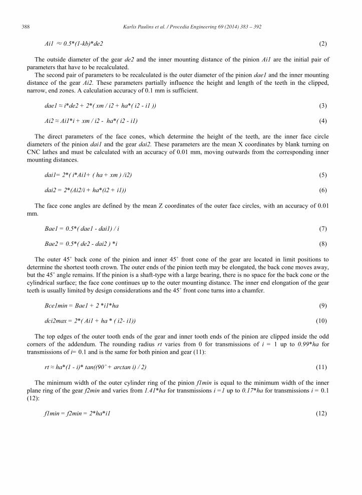
The outside diameter of the gear de2 and the inner mounting distance of the pinion Ai1 are the initial pair of parameters that have to be recalculated.
The second pair of parameters to be recalculated is the outer diameter of the pinion dae1 and the inner mounting distance of the gear Ai2. These parameters partially influence the height and length of the teeth in the clipped, narrow, end zones. A calculation accuracy of 0.1 mm is sufficient.
dae1 ≈ i*de2 + 2*( xm / i2 + ha*( i2 - i1 )) (3)
Ai2 ≈ Ai1*i + xm / i2 - ha*( i2 - i1) (4)
The direct parameters of the face cones, which determine the height of the teeth, are the inner face circle diameters of the pinion dai1 and the gear dai2. These parameters are the mean X coordinates by blank turning on CNC lathes and must be calculated with an accuracy of 0.01 mm, moving outwards from the corresponding inner mounting distances.
dai1= 2*( i*Ai1+ ( ha + xm ) /i2) (5)
dai2 = 2*(Ai2/i + ha*(i2 + i1)) (6)
The face cone angles are defined by the mean Z coordinates of the outer face circles, with an accuracy of 0.01 mm.
Bae1 = 0.5*( dae1 - dai1) / i (7)
Bae2 = 0.5*( de2 - dai2 ) *i (8)
The outer 45˚ back cone of the pinion and inner 45˚ front cone of the gear are located in limit positions to determine the shortest tooth crown. The outer ends of the pinion teeth may be elongated, the back cone moves away, but the 45˚ angle remains. If the pinion is a shaft-type with a large bearing, there is no space for the back cone or the cylindrical surface; the face cone continues up to the outer mounting distance. The inner end elongation of the gear teeth is usually limited by design considerations and the 45˚ front cone turns into a chamfer.
Bce1min = Bae1 + 2 *i1*ha (9)
dci2max = 2*( Ai1 + ha * ( i2- i1)) (10)
The top edges of the outer tooth ends of the gear and inner tooth ends of the pinion are clipped inside the odd corners of the addendum. The rounding radius rt varies from 0 for transmissions of i = 1 up to 0.99*ha for transmissions of i= 0.1 and is the same for both pinion and gear (11):
rt ≈ ha*(1 - i)* tan((90˚ + arctan i) / 2) (11)
The minimum width of the outer cylinder ring of the pinion f1min is equal to the minimum width of the inner plane ring of the gear f2min and varies from 1.41*ha for transmissions i =1 up to 0.17*ha for transmissions i = 0.1 (12):
f1min = f2min = 2*ha*i1 (12)

389 Karlis Paulins et al. / Procedia Engineering 69 ( 2014 ) 383 – 392
4. A recalculation example
As an example of recalculation, we have taken a spiral bevel gear pair from a round baler transmission, with 17 and 29 teeth. (Fig. 3)
Fig. 3. Typical example of a 17/29 spiral bevel gear pair.

390 Karlis Paulins et al. / Procedia Engineering 69 ( 2014 ) 383 – 392
The original outer diameter of the gear is 177.14 mm and the outer pitch diameter is 174.0 mm. The customary display of the dimensions differs from that proposed for optimised tooth-end geometry. The essential dimensions are compared in figures 3 and 4. For recalculation purposes, the rounded diameter de2=175 mm can be accepted for the outer cylinder (Fig. 4) replacing the two aforementioned diameters.
Fig. 4. 17/29 Spiral bevel gear pair with optimised tooth ends.

391 Karlis Paulins et al. / Procedia Engineering 69 ( 2014 ) 383 – 392
The face width is 31 mm and the original face width factor is kb=0.3074. The other aforementioned given parameters that remain the same for the original and the recalculation are ha=4.2 mm, xm= 1.1 mm, i=0.586207, i1= 0.505719 and i2= 0.862698. The mounting distance of the pinion is 95 mm and that of the gear is 65 mm. The recalculation begins with the inner mounting distance of the pinion, calculated as Ai1= 60.6025 and rounded to 60.5 mm. A similar gear distance is Ai2= 35.24 or after rounding 35.2 mm. In accordance with the proposed calculation method, the face cone is determined by the inner mounting distance (5) and diameter of the inner face circle (6). The distance between the inner and customary (outer) mounting is easy to measure permanently.
In accordance with the customary calculation method, the face cone is determined by the outer mounting distance and the diameter of the outer face circle (Fig. 3 – 111.14 mm and 177.14 mm). The possibility to measure the diameter of the outer face circle and the distance up to outer face circle, for example 10.68 mm or 16.67 mm, is lost after inexact chamfering, as shown in “red” on fig. 3. The diameters ф? of the outer cylindrical chamfers can be relatively freely chosen by the designer. However, designers often “forget” to give the frontal plane chamfers (coordinate ? on Fig.3) on drawings. The frontal chamfers then fully depend on the turner or locksmith. In Fig. 3, the possible theoretical, customary, inner mounting distances, their associated inner face cone diameters and axial lengths of the gears are shown in brackets.
In accordance with the proposed calculation method, the chamfering is included in the tooth geometry. The outer diameter of the pinion dae1 = 108.1349 ≈ 108.1 mm, the inner mounting distance of the gear Ai2 =
35.24 ≈ 35.2 mm. The inner face circle diameters of the face cones dai1= 83.22 mm and dai2 = 131.49 mm and the axial coordinates of the outer face circles Bae1 = 21.23 mm and Bae2 = 12.75 mm are calculated with an accuracy 0.01 mm.
The tooth-end cone positions can be rounded to 0.5 mm: Bce1min = 25.478 ≈ 25.5 mm and dci2max = 123.09 ≈ 123 mm.
4. Conclusion
Lifelong experience, ongoing research and hundreds of optimised spiral bevel gears have identified a number of advantages and led to considerable improvements in gear-cutting technology:
1. Increased tooth end strength in the event of unexpected contact pattern deviation, even after significant wear of the teeth and/or bearings. 2. Easier protection of the crown gear outer tooth ends against damage during the production process. 3. When the mating pinion is designed without a complementary front cone, it is pointless to design the gear with a complementary back cone. 4. Simplification of gear blank geometry. 5. More suitable geometry for modern machining and checking of blanks, due to the inclusion of chamfer-type surfaces in the basic design. 6. The reduction of the outer diameter of the gear and axial dimension, whilst offering additional strength. 7. The possibility to use small, cylindrical and plane surfaces for separate radial and axial run-out checking, without forming special surfaces for checking. 8. The use of complementary cones is partly due to historic practice.
These conclusions are having significant impact to the practical work and could be directly applied into the
industrial manufacturing and especially in field of the tailor-made repair works of the spiral bevel gears. Scientifically justified simplification of the gear blank geometry is directly related with the decrease of manufacturing time and related production costs. Taking into account scale and number of the spiral bevel gears produced today for consumer needs, such optimization would provide enormous economic benefits related not only to the reduction of the actual production costs but also to considerable increase of the life span of the gear transmissions.
392 Karlis Paulins et al. / Procedia Engineering 69 ( 2014 ) 383 – 392
Acknowledgements
This article is based on the original work of Docent Kārlis Pauliņš, who devoted his professional life to the research of gear transmissions. This is a tribute to Docent Pauliņš' knowledge, commitment and professionalism demonstrated also through his extraordinary scientific achievements, as well as to his tutorship of several generations of mechanical engineers who studied at Riga Technical University.
References
[1] Wildhaber, E., Helical Gearing, U.S. Patent No. 1,601,750, 1926. [2] Novikov, M.L., Patent No. 109750, U.S.S.R., 1956. [3] Valdman, M., Paulins, K., Rozins, V., Increasing of durability of self-driven drilling rigs, Chemical and Petroleum Engineering, Issue No. 11,
1978, Moscow, pp. 46-47 //Вальдман М.Я., Паулиньш К.К., Розин В.Т. Повышение долговечности роторов самоходных буровых установок. In: Химическое и нефтяное машиностроение, № 11, с. 46 - 47 Москва 1978 г.
[4] Paulins, K., Novikov's gear with modified tooth ends, Gear transmission durability, Riga Polytechnic Institute, Issue No 12, 1975, Riga, pp. 70-79 //Паулиньш К.К. Конические передачи Новикова с модификацией торцов зубев. Рижский политехнический институт, Долговечность зубчатых передач, Выпуск 12. 70 -79 .РПИ, Рига 1975.
[5] Paulins, K., Arc method for the cutting of bevel gear teeth, Author's certificate (patent) No. 550247, U.S.S.R., 1977 //A.c. 550247 (CCCP). Способ нарезания обкаткой дуговых зубьев конических колес / K.K.Паулиньш. – Заявл. 02.07.71, № 1673059/08; Oпубл. в Б. И., 1977, № 10. MKИ B23 F 19/12.
[6] Paulins, K., Novikov's gear with modified tooth ends, Gear transmission durability, Riga Polytechnic Institute, Issue No 12, 1975, Riga, pp. 59-69 //Паулиньш К.К. Конические передачи Новикова с особой формой торцов зубев. Рижский политехнический институт, Долговечность зубчатых передач, Выпуск 12. 59- 69. РПИ, Рига 1975.
[7] Paulins, K., Technological issues of turning forms and new ways to normalize the size of bevel gears, Riga Polytechnic Institute, 1974, Riga, pp. 15-21 //Паулиньш K.K. Texнологичность токарной формы и новые пути нормализации размеров зубчатых венцов конических колес. Bопросы механики и машиностроения, вып. 5. Pига, изд-во PПИ, c. 15-42. 1974.
[8] Paulins K., Optimale Geometrie der Zahnenden von Spiralkegelraedern, Technische Universitaet Ilmenau, 44. Internationales Wissenschaftliches Kolloquium Band 3, TUI. Ilmenau, 1999, pp. 279-283.
[9] Paulins K., Riekstins E., Tokmachovs O. Optimal Geometry of Tooth End Surfaces for Spiral Bevel and Hypoid Gears, 6th International Congress of the Croatian Society of Mechanics, Dubrovnik, 2009.
[10] Su, J.-Z., Fang, Z.-D. Optimization design and test of stability of contact patterns of spiral bevel gears. Hangkong Dongli Xuebao/Journal of Aerospace Power, 27 (11), pp. 2622-2628. 2012.
[11] Fan, Q. Optimization of face cone element for spiral bevel and hypoid gears. Proceedings of the ASME Design Engineering Technical Conference, 8, pp. 189-195. 2011.