
SPINNER || AIR TRAFFIC CONTROL ROTARY JOINTS · SPINNER || AIR TRAFFIC CONTROL ROTARY JOINTS. 4 ||...
44
SPINNER || AIR TRAFFIC CONTROL ROTARY JOINTS Edition B | 2015 High Frequency Performance Worldwide www.spinner-group.com
Transcript of SPINNER || AIR TRAFFIC CONTROL ROTARY JOINTS · SPINNER || AIR TRAFFIC CONTROL ROTARY JOINTS. 4 ||...

SPINNER || AIR TRAFFIC CONTROL ROTARY JOINTS
Edition B | 2015
High Frequency Performance Worldwidewww.spinner-group.com

The specifications given here as well as the illustrations are for advance information. They shall only be confirmed by SPINNER‘s written offer and are subject to technical amendments.
© 2015 SPINNER GmbH
On our website you will find our latest updates. As your contribution to environmental protection you can also down-load our catalogues as PDF files. This catalogue has been printed on wood-free Primaset paper.

SPINNER || AIR TRAFFIC CONTROL ROTARY JOINTS
|| 3Data subject to change without notice – Edition B
CONTENT
Rotary Joints
3 Channel Coax Rotary Joints ....................................................................................... 6
3 Channel Waveguide Coax Rotary Joints .................................................................. 10
4 Channel Coax Rotary Joints ..................................................................................... 12
4 Channel Waveguide Coax Rotary Joints .................................................................. 14
6 Channel Waveguide Coax Rotary Joints .................................................................. 15
7 Channel Coax Rotary Joints ..................................................................................... 21
7 Channel Waveguide Coax Rotary Joints .................................................................. 22
9 Channel Coax Rotary Joints ..................................................................................... 25
Rotary Joints & Slip Rings Specification ........................................................................ 26
Technical Annex .............................................................................................................. 30
3 C
hann
el4
Cha
nnel
7 C
hann
el9
Cha
nnel
6 C
hann
el

SPINNER || AIR TRAFFIC CONTROL ROTARY JOINTS
4 || Data subject to change without notice – Edition B
As an international leader in innovation, SPINNER is a reliable supplier of advanced components for radar systems. Since the early sixties SPINNER sets standards worldwide. Our innovations in this field together with our technical know-how and our top quality claim have allowed us to become one of the leading rotary joint manufacturers.
Rotary joints are needed in radar systems, wherever signals have to be transmitted between a fixed platform and a conti-nuously rotating antenna system. These include the broad field of Air Traffic Control (ATC) radar systems like Surface Movement Radar (SMR), Precision Approach Radar (PAR), Air Surveillance Radar (ASR), en-route radar or Doppler Weather Radars (DWR).
Special benefits of SPINNER rotary joints are their compact design, excellent VSWR and low insertion loss, low variation of transmission properties during rotation, and high crosstalk attenuation between the individual channels over the whole frequency range.The wealth of experience that our engineers have with rotary joints in military use and our commitment to continuous product improvement are the basis of our great success. When it comes to application in ATC, all major customers in Europe already trust in our rotary joints.
As an additional service SPINNER offers repair and mainte-nance of all ATC rotary joint brands.
Safety is the highest demand in a high-density
airspace. This affects air traffic management in
the civil and military domain. This relies mostly on
highly sophisticated radar systems for airport surface
movements, air surveillance, en-route tracking and
weather observation.

SPINNER || AIR TRAFFIC CONTROL ROTARY JOINTS
|| 5Data subject to change without notice – Edition B
SPINNER || SlIP RINg SPEcIfIcatIoN
110 ||
Data subject to change without notice – Edition B
General mechanical data
Average rotational speed, max.
rpm
Rotating speed, max.
rpm
Turning torque static, max.
Nm
Turning torque dynamic, max.
Nm
Surface finish
dimenSiOnS / limitatiOn / cOnditiOnS
Outer diameter, max.
m
m
Free inner bore
yes, ........
.. mm
no
Total length
m
m
Weight, max.
k
g
electrical reQUirementS - total number of ways:
Designation of groups
a
B
c
d
e
F
Number of ways per group
Application
Normal current
A
A
A
A
A
A
Maximum current / period
Voltage
V
V
V
V
V
V
Frequency
kHz
kHz
kHz
kHz
kHz
kHz
Isolation resistance / 500 V DC
Dielectrical strength
Resistance (End to End)
Noise
Ω
Ω
Ω
Ω
Ω
Ω
Crosstalk
Insertion loss
dB
dB
dB
dB
dB
dB
Impedance
VSWR, max.
Protection earth
Switch-off time
....
reQUired QUalitiY dOcUmentS
CoC according DIN 55350-18
Government source inspection
Environmental test
Other ..........
............
............
.........
............
............
............
............
.....
General envirOnmental cOnditiOnS
Isolation (per EN60529)
Vibration / Shock / A
cceleration
liFe time | maintenance
Operation time / D
uty cycle
(Hour per time interval)
Life, min.
.... x ...
. revolutions
Maintenance
.... x ...
. revolutions
Brush change
.... x ...
. revolutions
Warranty conditions
SPINNER || RotaRy joINt SPEcIfIcatIoN
108 || Data subject to change without notice – Edition B
RF channel chaRacteRistics - total number of channels:
Channel designation 1 2 3 4 5 6
Interfaces
Style
Frequency range
Peak power, max.
Average power, max.
VSWR, max.
VSWR WOW, max.
Insertion loss, max.
Insertion loss WOW, max.
Phase WOW, max.
Absolute phase difference
Isolation, min.
DC carrying capability, max.
....
GeneRal mechanical data
Rotating speed, max. rpm
Life, min. .... x .... revolutions
Starting torque, max. Nm
Torque during rotation, max. Nm
Case material
Case surface finish, per MIL-C-5541
Weight, approx. kg
dOcUments ReQUiRed
CoC according DIN 55350-18
Government Source Inspection
Environmental Test
Other ........................................
..................................................
Company: _______________________________________ Contact Name: _______________________________________________________
Address: _________________________________________ Phone / Fax: ______________________
_________________________________________ E-Mail: _____________________________ @ ______________________________
Your Ref: ________________________________________________________________________ Date: __________________________
Project / Delivery Contry: __________________________________________________________________________________________________
Application: military use ground airborne space RF rotary joint FOJ rotary joint
civil use naval other _________________ Media rotary joint Encoder
GeneRal enviROnmental cOnditiOnsOperation
Ambient temperature range .... °C to .... °C
Relative humidity, max. %
IP protection level IP..
storage
Ambient temperature range .... °C to .... °C
Relative humidity, max. %
Required Quantity: Prototype ________ Serial ________ Delivery Period: __________________________________________
CUSTOM-MADE ROTARY JOINTS
For an enquiry to a custom-made rotary joint, our specification sheet assists you defining your system. Please find it on page 26.

SPINNER || AIR TRAFFIC CONTROL ROTARY JOINTS
6 || Data subject to change without notice – Edition B
3 CHANNEL COAX ROTARY JOINT | L-BAND
RF channel characteristics BN 53 23 48
Channel designation Channel 1 Channel 2 Channel 3
Interfaces N-f (50 Ω)
Frequency range 0.9 - 1.2 GHz
Peak power, max. 10 kW
Average power, max. 300 W 50 W 50 W
VSWR, max. 1.2 @ 1 - 1.1 GHz1.3 @ 0.9 - 1.2 GHz
VSWR WOW, max. 0.05
Insertion loss, max. 0.4 dB @ 1 - 1.1GHz0.6 dB @ 0.9 - 1.2 GHz
Insertion loss WOW, max. 0.05 dB
Isolation, min. 60 dB
Phase WOW, max. 2 deg.
General mechanical data
Rotating speed, max. 200 rpm
Life, min. 200 x 106 revolutions
Starting torque, max. 5 Nm @ room temperature
Torque during rotation, max. 5 Nm @ room temperature
Case material alluminium alloy
Case surface finish, chromate conversion coat per MIL-DTL-5541 type 1 or type 2
Weight, approx. 8 kg
General environmental conditions
Operation
Ambient temperature range -55 °C ... +85 °C
Relative humidity, max. 95% (non-condensing)
IP protection level IP60
Storage
Ambient temperature range -55 °C ... +85 °C
Relative humidity, max. 95% (non-condensing)
15.1
141.6
291.7
310.5
135
6.5
60°
rotational gap

SPINNER || AIR TRAFFIC CONTROL ROTARY JOINTS
|| 7Data subject to change without notice – Edition B
3 CHANNEL COAX ROTARY JOINT | L-BAND
RF channel characteristics BN 53 23 49
Channel designation Channel 1 Channel 2 Channel 3
Interfaces N-f (50 Ω)
Frequency range 1.0 - 1.11 GHz
Peak power, max. 20 kW
Average power, max. 500 W
VSWR, max. / typ. 1.3 / 1.2
VSWR WOW, max. 0.05
Insertion loss, max. / typ. 0.5 dB / 0.4 dB
Insertion loss WOW, max. 0.03 dB
Isolation, min. 60 dB
Phase WOW, max. 1.5 deg.
Encoder characteristics
Type / manufacturer 2 x DFS60A-TGAA65536 (Fa. SICK-Stegmann AG)
General mechanical data
Rotating speed, max. 60 rpm
Life, min. 200 x 106 revolutions
Starting torque, max. 2 Nm @ room temperature
Torque during rotation, max. 2 Nm @ room temperature
Case material aluminium alloy
Case surface finish chromate conversion coat per MIL-DTL-5541 type 1 or type 2 / painted
Weight, approx. 17 kg
General environmental conditions
Operation
Ambient temperature range -55 °C ... +71 °C (encoder excluded)
Relative humidity, max. 95% (non-condensing)
IP protection level IP50
Storage
Ambient temperature range -40 °C ... +85 °C (encoder excluded)
Relative humidity, max. 95% (non-condensing)
24
9
50.896.1
141.4
81
190.9241.9
230
9.5
rotational gap254.9
60°
3 C
hann
el

SPINNER || AIR TRAFFIC CONTROL ROTARY JOINTS
8 || Data subject to change without notice – Edition B
3 CHANNEL COAX ROTARY JOINT | L-BAND
RF channel characteristics BN 53 25 17
Channel designation Channel 1 Channel 2 Channel 3
Interfaces N-f (50 Ω)
Frequency range 0.95 - 1.15 GHz
Peak power, max. 10 kW
Average power, max. 200 W 100 W 100 W
VSWR, max. 1.25
VSWR WOW, max. 0.05
Insertion loss, max. / typ. 0.5 dB / 0.4 dB
Insertion loss WOW, max. 0.03 dB
Isolation, min. 60 dB
Phase WOW, max. 1.5 deg.
Encoder characteristics
Type / manufacturer 2 x DHO5_14//RP29//3600 / BEI-IDEACOD, France
General mechanical data
Rotating speed, max. 200 rpm
Life, min. 200 x 106 revolutions
Starting torque, max. 2 Nm @ room temperature
Torque during rotation, max. 2 Nm @ room temperature
Case material aluminium alloy
Case surface finish chromate conversion coat per MIL-DTL-5541 type 1 or type 2 / painted
Weight, approx. 14 kg
General environmental conditions
Operation
Ambient temperature range -55 °C ... +71 °C (encoder excluded)
Relative humidity, max. 95% (non-condensing)
IP protection level IP54
Storage
Ambient temperature range -55 °C ... +85 °C (encoder excluded)
Relative humidity, max. 95% (non-condensing)
20
0
58.3128.3
198.3279.4
319.4
38.8 379rotational gap
180
9
60°

SPINNER || AIR TRAFFIC CONTROL ROTARY JOINTS
|| 9Data subject to change without notice – Edition B
3 CHANNEL COAX ROTARY JOINT | L-BAND
RF channel characteristics BN 53 23 RA
Channel designation Channel 1 Channel 2 Channel 3
Interfaces N-f (50 Ω)
Frequency range 1.0 - 1.11 GHz
Peak power, max. 20 kW
Average power, max. 200 W
VSWR, max. 1.3
VSWR WOW, max. 0.05
Insertion loss, max. 0.5 dB
Insertion loss WOW, max. 0.05 dB
Isolation, min. 60 dB
Phase WOW, max. 1.5 deg.
General mechanical data
Rotating speed, max. 60 rpm
Life, min. 200 x 106 revolutions
Starting torque, max. 2 Nm @ room temperature
Torque during rotation, max. 2 Nm @ room temperature
Case material aluminium alloy
Case surface finish chromate conversion coat per MIL-DTL-5541 type 1 or type 2 / painted
Weight, approx. 22 kg
General environmental conditions
Operation
Ambient temperature range -55 °C ... +71 °C (encoder excluded)
Relative humidity, max. 95% (non-condensing)
IP protection level IP50
Storage
Ambient temperature range -55 °C ... +85 °C (encoder excluded)
Relative humidity, max. 95% (non-condensing)
Encoder characteristics
Type / manufacturer 3x DFS60 (Fa. SICK-Stegmann AG)
Slip rings characteristics
Total number of ways 6
367.4327.4
287.4
52.1
393
141.496.1
50.8
n24
9
n9
n23060°
rotational gap
Ω 3 C
hann
el
SPINNER || AIR TRAFFIC CONTROL ROTARY JOINTS
10 || Data subject to change without notice – Edition B
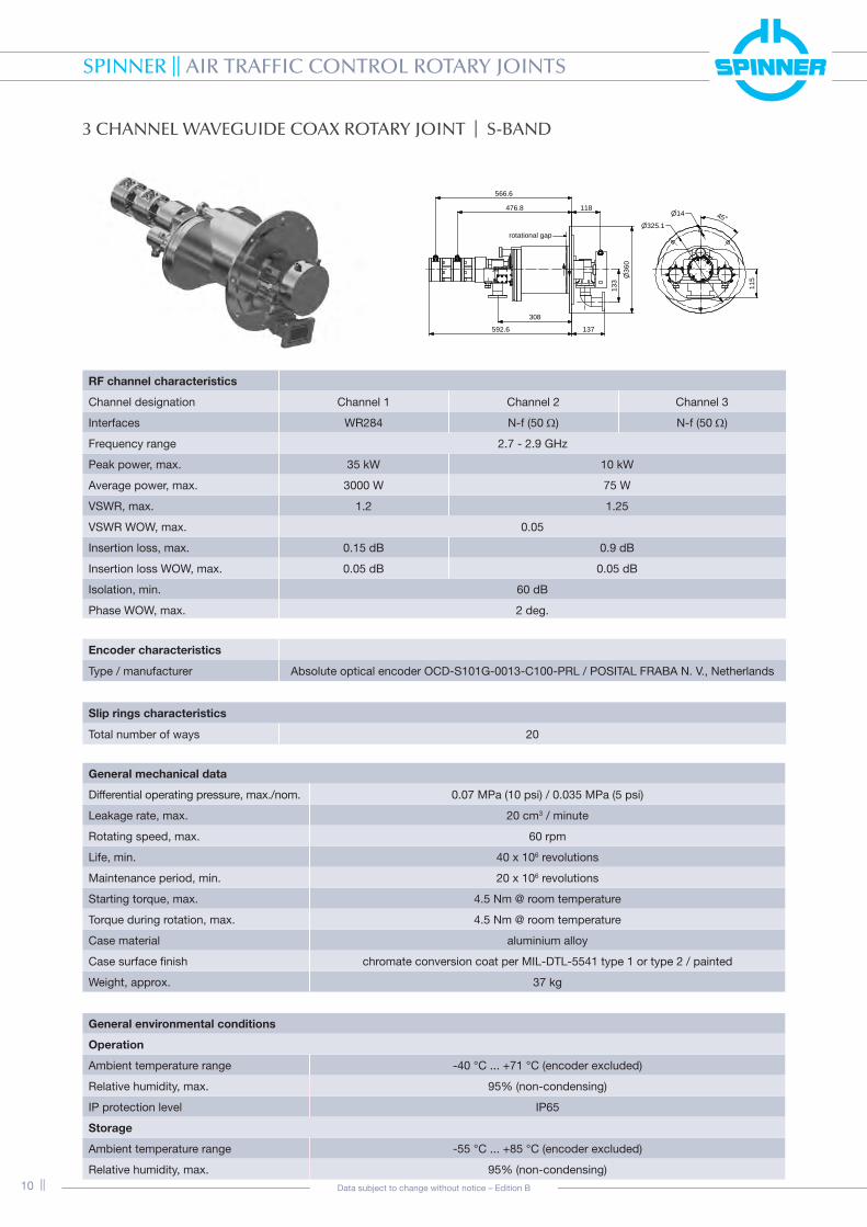
3 CHANNEL WAVEGUIDE COAX ROTARY JOINT | S-BAND
RF channel characteristics BN 53 23 BR
Channel designation Channel 1 Channel 2 Channel 3
Interfaces WR284 N-f (50 Ω) N-f (50 Ω)
Frequency range 2.7 - 2.9 GHz
Peak power, max. 35 kW 10 kW
Average power, max. 3000 W 75 W
VSWR, max. 1.2 1.25
VSWR WOW, max. 0.05
Insertion loss, max. 0.15 dB 0.9 dB
Insertion loss WOW, max. 0.05 dB 0.05 dB
Isolation, min. 60 dB
Phase WOW, max. 2 deg.
General mechanical data
Differential operating pressure, max./nom. 0.07 MPa (10 psi) / 0.035 MPa (5 psi)
Leakage rate, max. 20 cm3 / minute
Rotating speed, max. 60 rpm
Life, min. 40 x 106 revolutions
Maintenance period, min. 20 x 106 revolutions
Starting torque, max. 4.5 Nm @ room temperature
Torque during rotation, max. 4.5 Nm @ room temperature
Case material aluminium alloy
Case surface finish chromate conversion coat per MIL-DTL-5541 type 1 or type 2 / painted
Weight, approx. 37 kg
General environmental conditions
Operation
Ambient temperature range -40 °C ... +71 °C (encoder excluded)
Relative humidity, max. 95% (non-condensing)
IP protection level IP65
Storage
Ambient temperature range -55 °C ... +85 °C (encoder excluded)
Relative humidity, max. 95% (non-condensing)
Encoder characteristics
Type / manufacturer Absolute optical encoder OCD-S101G-0013-C100-PRL / POSITAL FRABA N. V., Netherlands
Slip rings characteristics
Total number of ways 20
n36
0
118
566.6
476.8
133
137
308
592.6
115
n14 45°n325.1
rotational gap

SPINNER || AIR TRAFFIC CONTROL ROTARY JOINTS
|| 11Data subject to change without notice – Edition B
Encoder characteristics
Type / manufacturer 2 x DFS60A-TGAA65536 / Firma SICK
Slip rings characteristics
Total number of ways 15
3 CHANNEL WAVEGUIDE COAX ROTARY JOINT | S-BAND
RF channel characteristics BN 53 23 52
Channel designation Channel 1 Channel 2 Channel 3
Interfaces special flange WR284 N-f (50 Ω) N-f (50 Ω)
Frequency range 2.7 - 2.9 GHz
Peak power, max. 200 kW 10 kW 10 kW
Average power, max. 3500 W 75 W 75 W
VSWR, max. 1.2 1.25 1.25
VSWR WOW, max. 0.05 0.05 0.05
Insertion loss, max. 0.15 dB 0.9 dB 0.9 dB
Insertion loss WOW, max. 0.03 dB 0.03 dB 0.03 dB
Isolation, min. 70 dB 60 dB
Phase WOW, max. 1.5 deg. 2 deg.
CH 1
Encoder 1
Encoder 2
133`
1
270`3 137`1
141`5638.4`10 14n `0.58 x
n325.12
45°
115`
2
(779.4)
CH 1
360
Ø285
- 0.0
5Ø
General mechanical data
Differential operating pressure, max./nom. 0.07 MPa (10 psi) / 0.035 MPa (5 psi)
Leakage rate, max. 25 cm3 / minute
Rotating speed, max. 60 rpm
Life, min. 40 x 106 revolutions
Maintenance period, min. 20 x 106 revolutions
Starting torque, max. 4.5 Nm @ room temperature
Torque during rotation, max. 4.5 Nm @ room temperature
Case material aluminium alloy
Case surface finish chromate conversion coat per MIL-DTL-5541 type 1 or type 2 / painted
Weight, approx. 35 kg
General environmental conditions
Operation
Ambient temperature range -40 °C ... +71 °C (encoder excluded)
Relative humidity, max. 95% (non-condensing)
IP protection level IP65
Storage
Ambient temperature range -55 °C ... +85 °C (encoder excluded)
Relative humidity, max. 95% (non-condensing)
3 C
hann
el

SPINNER || AIR TRAFFIC CONTROL ROTARY JOINTS
12 || Data subject to change without notice – Edition B
4 CHANNEL COAX ROTARY JOINT | L-BAND
RF channel characteristics BN 53 25 BP
Channel designation Channel 1 Channel 2 Channel 3 Channel 4
Interfaces N-f (50 Ω)
Frequency range 1.03 - 1.09 GHz 1.2 - 1.4 GHz
Peak power, max. 20 kW 20 kW
Average power, max. 500 W 100 W
VSWR, max. 1.25 1.3
VSWR WOW, max. 0.05
Insertion loss, max. 0.8 dB 1.2 dB
Insertion loss WOW, max. 0.05 dB
Isolation, min. 60 dB
Phase WOW, max. 1.5 deg.
General mechanical data
Rotating speed, max. 60 rpm
Life, min. 200 x 106 revolutions
Starting torque, max. 3 Nm @ room temperature
Torque during rotation, max. 3 Nm @ room temperature
Case material aluminium alloy
Case surface finish chromate conversion coat per MIL-DTL-5541 type 1 or type 2 / painted
Weight, approx. 20 kg
General environmental conditions
Operation
Ambient temperature range -55 °C ... +71 °C (encoder excluded)
Relative humidity, max. 95% (non-condensing)
IP protection level IP54
Storage
Ambient temperature range -55 °C ... +85 °C (encoder excluded)
Relative humidity, max. 95% (non-condensing)
Encoder characteristics
Type / manufacturer 2 x DHO5_14//RP29//3600 / BEI-IDEACOD, France
70
30
15.5 108 191.5140.7
95.249.9
4.5 n225
n6.5
n207.560°
rotational gap

SPINNER || AIR TRAFFIC CONTROL ROTARY JOINTS
|| 13Data subject to change without notice – Edition B
4 CHANNEL COAX ROTARY JOINT | L-BAND
RF channel characteristics BN 53 24 17
Channel designation Channel 1 Channel 2 Channel 3 Channel 4
Interfaces N-f (50 Ω)
Frequency range 1.215 - 1.4 GHz
Peak power, max. 10 W
Average power, max. 50 W
VSWR, max. 1.25
VSWR WOW, max. 0.05
Insertion loss, max. 0.5 dB
Insertion loss WOW, max. 0.05 dB
Isolation, min. 60 dB
Phase WOW, max. 2 deg.
Encoder characteristics
Type / manufacturer 2 x DHO5_14//RP29//3600 / BEI-IDEACOD, France
Slip rings characteristics
Total number of ways 14
General mechanical data
Rotating speed, max. 60 rpm
Life, min. 40 x 106 revolutions
Maintenance period, min. 20 x 106 revolutions
Starting torque, max. 4.5 Nm @ room temperature
Torque during rotation, max. 4.5 Nm @ room temperature
Case material aluminium alloy
Case surface finish chromate conversion coat / painted
Weight, approx. 25 kg
General environmental conditions
Operation
Ambient temperature range -40 °C ... +71 °C (encoder excluded)
Relative humidity, max. 95% (non-condensing)
IP protection level IP54
Storage
Ambient temperature range -55 °C ... +85 °C (encoder excluded)
Relative humidity, max. 95% (non-condensing)
70174.7
200
Ø
142101.6
rotational gap
505.8465.8
100
91.1
n180
60°
30°
n9
70 70
4 C
hann
el

SPINNER || AIR TRAFFIC CONTROL ROTARY JOINTS
14 || Data subject to change without notice – Edition B
4 CHANNEL WAVEGUIDE COAX ROTARY JOINT | S-BAND
RF channel characteristics BN 53 24 19
Channel designation Channel 1 Channel 2 Channel 3 Channel 4
Interfaces special flange WR284 N-f (50 Ω)
Frequency range 2.7 - 3.1 GHz
Peak power, max. 200 kW 5 kW
Average power, max. 3500 W 75 W
VSWR, max. / typ. 1.25 / 1.15 1.25 / 1.15
VSWR WOW, max. 0.05 0.05
Insertion loss, max. / typ. 0.3 dB / 0.2 dB 1 dB / 0.8 dB
Insertion loss WOW, max. 0.03 dB 0.03 dB
Isolation, min. 60 dB
Phase WOW, max. 1.5 deg. 2 deg.
General mechanical data
Differential operating pressure, max. / nom. 0.01 MPa (1.4 psi) / 0.0014 MPa (0.2 psi)
Leakage rate, max. 25 cm3 / minute
Rotating speed, max. 60 rpm
Life, min. 200 x 106 revolutions
Maintenance period, min. 20 x 106 revolutions
Starting torque, max. 10 Nm @ room temperature
Torque during rotation, max. 10 Nm @ room temperature
Case material aluminium alloy
Case surface finish chromate conversion coat per MIL-DTL-5541 type 1 or type 2 / painted
Weight, approx. 35 kg
General environmental conditions
Operation
Ambient temperature range -40 °C ... +71 °C
Relative humidity, max. 95% (non-condensing)
IP protection level IP65
Storage
Ambient temperature range -55 °C ... +85 °C
Relative humidity, max. 95% (non-condensing)
rotational gap
527.4617.25
707.1741.65
867.61
133
360
28
5
32545° 14

SPINNER || AIR TRAFFIC CONTROL ROTARY JOINTS
|| 15Data subject to change without notice – Edition B
6 CHANNEL WAVEGUIDE COAX ROTARY JOINT | L-BAND / L-BAND
RF channel characteristics
Channel designation Channel 1 Channel 2 Channel 3 Channel 4 Channel 5 Channel 6
Interfaces WR 650 N-f (50 Ω)
Frequency range 1.2 - 1.4 GHz 1.0 - 1.11 GHz
Peak power, max. 400 kW 20 kW
Average power, max. 11 kW 440 W
VSWR, max. 1.25 1.3
VSWR WOW, max. 0.05
Insertion loss, max. 0.2 dB 0.75 dB 0.95 dB
Insertion loss WOW, max. 0.05 dB
Isolation, min. 60 dB
Phase WOW, max. 1.5 deg.
Encoder characteristics
Type / manufacturer 2 each DHO5_14//RP29//3600 / BEI-IDEACOD, France
Slip rings characteristics
Total number of ways 38
General mechanical data
Differential operating pressure, max. / nom. 0.015 MPa (2 psi) / 0.007 MPa (1 psi)
Leakage rate, max. 25 cm3 / minute
Rotating speed, max. 60 rpm
Life, min. 40 x 106 revolutions
Maintenance period, min. 20 x 106 revolutions
Starting torque, max. 3 Nm @ room temperature
Torque during rotation, max. 3 Nm @ room temperature
Case material aluminium alloy
Case surface finish chromate conversion coat per MIL-DTL-5541 type 1 or type 2 / painted
Weight, approx. 85 kg
General environmental conditions
Operation
Ambient temperature range -40 °C ... +71 °C (encoder excluded)
Relative humidity, max. 95% (non-condensing)
IP protection level IP65
Storage
Ambient temperature range -55 °C ... +85 °C (encoder excluded)
Relative humidity, max. 95% (non-condensing)
717.1677.1
597.3
316.185.5
240.8
552506.7
461.4
n38
6
416
n35
0 120.
8
n8.5 n366
120.
2
20°
rotational gap
6 C
hann
el

SPINNER || AIR TRAFFIC CONTROL ROTARY JOINTS
16 || Data subject to change without notice – Edition B
6 CHANNEL WAVEGUIDE COAX ROTARY JOINT | S-BAND / L-BAND
RF channel characteristics BN 53 25 01
Channel designation Channel 1 Channel 2 Channel 3 Channel 4 Channel 5 Channel 6
Interfaces WR 284 N-f (50 Ω)
Frequency range 2.7 - 2.9 GHz 2.7 - 3.1 GHz 1 - 1.11 GHz
Peak power, max. 200 kW 10 kW 20 kW
Average power, max. 3500 W 75 W 100 W
VSWR, max. 1.2 1.25 1.3
VSWR WOW, max. 0.05
Insertion loss, max. 0.15 dB 0.9 dB 0.75 dB
Insertion loss WOW, max. 0.05 dB
Isolation, min. 70 dB 60 dB
Phase WOW, max. 1.5 deg. 2 deg. 1.5 deg.
Encoder characteristics
Type / manufacturer 2x DFS60A-TGAA65536 (Fa. SICK)
Slip rings characteristics
Total number of ways 20
General mechanical data
Differential operating pressure, max. / nom. 0.07 MPa (10 psi) / 0.035 MPa (5 psi)
Leakage rate, max. 25 cm3 / minute
Rotating speed, max. 60 rpm
Life, min. 40 x 106 revolutions
Maintenance period, min. 20 x 106 revolutions
Starting torque, max. 10 Nm @ room temperature
Torque during rotation, max. 10 Nm @ room temperature
Case material aluminium alloy
Case surface finish chromate conversion coat per MIL-DTL-5541 type 1 or type 2 / painted
Weight, approx. 50 kg
General environmental conditions
Operation
Ambient temperature range -40 °C ... +71 °C (encoder excluded)
Relative humidity, max. 95% (non-condensing)
IP protection level IP54
Storage
Ambient temperature range -55 °C ... +85 °C (encoder excluded)
Relative humidity, max. 95% (non-condensing)
n14
n325.1
707.7617.9
492.8447.5
402.2
360
Ø
830.7
141137270
133
766.7817.7
45°
rotational gap

SPINNER || AIR TRAFFIC CONTROL ROTARY JOINTS
|| 17Data subject to change without notice – Edition B
6 CHANNEL WAVEGUIDE COAX ROTARY JOINT | S-BAND / L-BAND
RF channel characteristics BN 53 25 18
Channel designation Channel 1 Channel 2 Channel 3 Channel 4 Channel 5 Channel 6
Interfaces WR 284 N-f (50 Ω)
Frequency range 2.7 - 2.9 GHz 2.7 - 3.1 GHz 1 - 1.11 GHz
Peak power, max. 200 kW 5 kW
Average power, max. 3500 W 75 W 200 W
VSWR, max. / typ. 1.2 1.25 / 1.15 1.3 / 1.2
VSWR WOW, max. 0.05
Insertion loss, max. / typ 0.15 dB / 0.1 dB 0.9 dB / 0.7 dB 0.75 dB / 0.6 dB
Insertion loss WOW, max. 0.05 dB
Isolation, min. 70 dB 60 dB
Phase WOW, max. 1.5 deg. 2 deg. 1.5 deg.
Encoder characteristics
Type / manufacturer 2 each DHO5S14/0B/2G29//16384//G6R BEI-Sensors, France
Slip rings characteristics
Total number of ways 23
General mechanical data
Differential operating pressure, max. / nom. 0.02 MPa (2.9psi) / 0.0014 MPa (0.2 psi)
Leakage rate, max. 25 cm3 / minute
Rotating speed, max. 60 rpm
Life, min. 40 x 106 revolutions
Maintenance period, min. 20 x 106 revolutions
Starting torque, max. 10 Nm @ room temperature
Torque during rotation, max. 10 Nm @ room temperature
Case material aluminium alloy
Case surface finish chromate conversion coat per MIL-DTL-5541 type 1 or type 2 / painted
Weight, approx. 54 kg
General environmental conditions
Operation
Ambient temperature range -40 °C ... +71 °C (encoder excluded)
Relative humidity, max. 95% (non-condensing)
IP protection level IP54
Storage
Ambient temperature range -55 °C ... +85 °C (encoder excluded)
Relative humidity, max. 95% (non-condensing)
rotational gap
45° 14
325
231.5
363.7409454.3
579.35669.2
973.9
133
285
36
0
6 C
hann
el
SPINNER || AIR TRAFFIC CONTROL ROTARY JOINTS
18 || Data subject to change without notice – Edition B
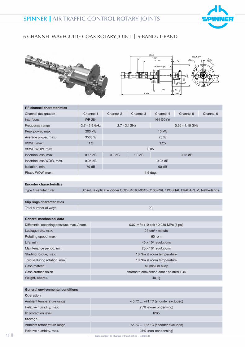
6 CHANNEL WAVEGUIDE COAX ROTARY JOINT | S-BAND / L-BAND
RF channel characteristics BN 53 25 BK
Channel designation Channel 1 Channel 2 Channel 3 Channel 4 Channel 5 Channel 6
Interfaces WR 284 N-f (50 Ω)
Frequency range 2.7 - 2.9 GHz 2.7 - 3.1GHz 0.95 - 1.15 GHz
Peak power, max. 200 kW 10 kW
Average power, max. 3500 W 75 W
VSWR, max. 1.2 1.25
VSWR WOW, max. 0.05
Insertion loss, max. 0.15 dB 0.9 dB 1.0 dB 0.75 dB
Insertion loss WOW, max. 0.05 dB 0.05 dB
Isolation, min. 70 dB 60 dB
Phase WOW, max. 1.5 deg.
Encoder characteristics
Type / manufacturer Absolute optical encoder OCD-S101G-0013-C100-PRL / POSITAL FRABA N. V., Netherlands
Slip rings characteristics
Total number of ways 20
General mechanical data
Differential operating pressure, max. / nom. 0.07 MPa (10 psi) / 0.035 MPa (5 psi)
Leakage rate, max. 25 cm3 / minute
Rotating speed, max. 60 rpm
Life, min. 40 x 106 revolutions
Maintenance period, min. 20 x 106 revolutions
Starting torque, max. 10 Nm @ room temperature
Torque during rotation, max. 10 Nm @ room temperature
Case material aluminium alloy
Case surface finish chromate conversion coat / painted TBD
Weight, approx. 48 kg
General environmental conditions
Operation
Ambient temperature range -40 °C ... +71 °C (encoder excluded)
Relative humidity, max. 95% (non-condensing)
IP protection level IP65
Storage
Ambient temperature range -55 °C ... +85 °C (encoder excluded)
Relative humidity, max. 95% (non-condensing)
687.6566.6
476.8 118
n36
0
146836.4
308 137
133
n14
n325.145°
115
rotational gap

SPINNER || AIR TRAFFIC CONTROL ROTARY JOINTS
|| 19Data subject to change without notice – Edition B
6 CHANNEL WAVEGUIDE COAX ROTARY JOINT | S-BAND / L-BAND
RF channel characteristics BN 53 25 BL
Channel designation Channel 1 Channel 2 Channel 3 Channel 4 Channel 5 Channel 6
Interfaces WR 284 N-f (50 Ω)
Frequency range 2.7 - 2.9 GHz 2.7 - 3.1 GHz 1.235 - 1.365 GHz
Peak power, max. 200 kW 10 kW
Average power, max. 3500 W 75 W
VSWR, max. 1.2 1.25
VSWR WOW, max. 0.05
Insertion loss, max. 0.15 dB 0.9 dB 1.0 dB 0.9 dB
Insertion loss WOW, max. 0.05 dB 0.05 dB
Isolation, min. 60 dB
Phase WOW, max. 1.5 deg. 2 deg.
Encoder characteristics
Type / manufacturer Absolute optical encoder OCD-S101G-0013-C100-PRL / POSITAL FRABA N. V., Netherlands
Slip rings characteristics
Total number of ways 20
General mechanical data
Differential operating pressure, max. / nom. 0.07 MPa (10 psi) / 0.035 MPa (5 psi)
Leakage rate, max. 25 cm3 / minute
Rotating speed, max. 60 rpm
Life, min. 40 x 106 revolutions
Maintenance period, min. 20 x 106 revolutions
Starting torque, max. 10 Nm @ room temperature
Torque during rotation, max. 10 Nm @ room temperature
Case material aluminium alloy
Case surface finish chromate conversion coat per MIL-DTL-5541 type 1 or type 2 / painted
Weight, approx. 48 kg
General environmental conditions
Operation
Ambient temperature range -40 °C ... +71 °C (encoder excluded)
Relative humidity, max. 95% (non-condensing)
IP protection level IP54
Storage
Ambient temperature range -55 °C ... +85 °C (encoder excluded)
Relative humidity, max. 95% (non-condensing)
n36
0
118
787.6666.6
576.8
146936.4408 137
133
n14
n325.145°
115
rotational gap
6 C
hann
el

SPINNER || AIR TRAFFIC CONTROL ROTARY JOINTS
20 || Data subject to change without notice – Edition B
6 CHANNEL WAVEGUIDE COAX ROTARY JOINT | S-BAND / L-BAND
RF channel characteristics BN 63 53 38
Channel designation Channel 1 Channel 2 Channel 3 Channel 4 Channel 5 Channel 6
Interfaces CPR 284 N-f (50 Ω)
Frequency range 2.7 - 2.9 GHz 1.0 - 1.12 GHz
Peak power, max. 30 kW 5 kW 250 W 20 kW
Average power, max. 3 kW 500 W 25 W 500 W
VSWR, max. 1.2 1.3
VSWR WOW, max. 1.05
Insertion loss, max. 0.15 dB 0.2 dB 0.5 dB 0.75 dB
Insertion loss WOW, max. 0.15 dB 0.05 dB
Isolation, min. 60 dB
Phase WOW, max. 2.5 deg. 2 deg.
Encoder characteristics
Type / manufacturer 219409-RX / INDUCTOSYN
Slip rings characteristics
Total number of ways 30
General mechanical data
Differential operating pressure, max. / nom. 0.07 MPa (10 psi) / 0.035 MPa (5 psi)
Leakage rate, max. 25 cm3 / minute
Rotating speed, max. 60 rpm
Life, min. 40 x 106 revolutions
Maintenance period, min. 20 x 106 revolutions
Starting torque, max. 50 Nm @ room temperature
Torque during rotation, max. 40 Nm @ room temperature
Case material aluminium alloy
Case surface finish chromate conversion coat per MIL-DTL-5541 type 1 or type 2 / painted
Weight, approx. 155 kg
General environmental conditions
Operation
Ambient temperature range -40 °C ... +71 °C
Relative humidity, max. 95% (non-condensing)
IP protection level IP54
Storage
Ambient temperature range -55 °C ... +85 °C
Relative humidity, max. 95% (non-condensing)
774428.9
216
157.5
114.
315
0
542
647
n8.7
M8x1.25 - 6H
n476.3 22.5°45°
rotational gap

SPINNER || AIR TRAFFIC CONTROL ROTARY JOINTS
|| 21Data subject to change without notice – Edition B
7 CHANNEL WAVEGUIDE COAX ROTARY JOINT | L-BAND
RF channel characteristics BN 53 26 SI
Channel designation Channel 1 Channel 2 Channel 3 Channel 4 Channel 5 Channel 6 Channel 7
Interfaces N-f (50 Ω)
Frequency range 1 - 1.15 GHz
Peak power, max. 20 kW 20 kW
Average power, max. 50 W 100 W
VSWR, max. / typ. 1.5/ 1.4
VSWR WOW, max. / typ. 0.1 / 0.05
Insertion loss, max. / typ. 0.85 dB / 0.75 dB 0.75 dB / 0.65 dB
Insertion loss WOW, max. / typ. 0.1 dB / 0.05 dB
Isolation, min. / typ. 60 dB / 80 dB
Phase WOW, max. 3 deg.
Slip rings characteristics
Total number of ways 32
General mechanical data
Rotating speed, max. 60 rpm
Life, min. 40 x 106 revolutions
Maintenance period, min. 20 x 106 revolutions
Starting torque, max. 10 Nm @ room temperature
Torque during rotation, max. 9 Nm @ room temperature
Case material aluminium alloy
Case surface finish chromate conversion coat per MIL-DTL-5541 type 1 or type 2 / painted
Weight, approx. 30 kg
General environmental conditions
Operation
Ambient temperature range -40 °C ... +71 °C
Relative humidity, max. 95% (non-condensing)
IP protection level IP65
Storage
Ambient temperature range -55 °C ... +85 °C
Relative humidity, max. 95% (non-condensing)
rotational gap
578.4 88.2
32545°14
250.5341.1
431.7522.3
36
0
7 C
hann
el

SPINNER || AIR TRAFFIC CONTROL ROTARY JOINTS
22 || Data subject to change without notice – Edition B
7 CHANNEL WAVEGUIDE COAX ROTARY JOINT | L-BAND
RF channel characteristics BN 53 26 SH
Channel designation Channel 1 Channel 2 Channel 3 Channel 4 Channel 5 Channel 6 Channel 7
Interfaces CPR-650F N-f (50 Ω)
Frequency range 1.2 - 1.4 GHz 0.95 - 1.15 GHz
Peak power, max. 400 KW 20 kW
Average power, max. 11000 W 440 W 300 W
VSWR, max. 1.25 1.3
VSWR WOW, max. 0.05
Insertion loss, max. 0.2 dB 0.65 dB 0.7 dB 0.75 dB 0.8 dB 0.85 dB 0.9 dB
Insertion loss WOW, max. 0.05 dB
Isolation, min. 70 dB 60 dB
Phase WOW, max. 1.5 deg. 2 deg.
Encoder characteristics
Type / manufacturer 2 each DHO5S14/0B/2G29//16384//G6R BEI-Sensors, France
Slip rings characteristics
Total number of ways 21
General mechanical data
Differential operating pressure, max. / nom. 0.02 MPa (2.9 psi) / 0.0014 MPa (0.2 psi)
Leakage rate, max. 25 cm3 / minute
Rotating speed, max. 60 rpm
Life, min. 50 x 106 revolutions
Maintenance period, min. 12.5 x 10⁶ revolutions
Starting torque, max. 18 Nm @ room temperature
Torque during rotation, max. 18 Nm @ room temperature
Case material aluminium alloy
Case surface finish chromate conversion coat per MIL-DTL-5541 type 1 or type 2 / painted
Weight, approx. 105 kg
General environmental conditions
Operation
Ambient temperature range -40 °C ... +71 °C (encoder excluded)
Relative humidity, max. 95% (non-condensing)
IP protection level IP65
Storage
Ambient temperature range -55 °C ... +85 °C (encoder excluded)
Relative humidity, max. 95% (non-condensing)
rotational gap
876.7 234.1
508
37.5°
45°
9
120.
2
53
5
430.1520.7
700.6
326.5 95.1

SPINNER || AIR TRAFFIC CONTROL ROTARY JOINTS
|| 23Data subject to change without notice – Edition B
7 CHANNEL WAVEGUIDE COAX ROTARY JOINT | S-BAND / L-BAND
RF channel characteristics BN 53 26 44
Channel designation Channel 1 Channel 2 Channel 3 Channel 4 Channel 5 Channel 6 Channel 7
Interfaces UG 585/U N-f (50 Ω)
Frequency range 2.7 - 3.1 GHz 1 - 1.1 GHz 2.7 - 3.1 GHz
Peak power, max. 1.5 MW 10 kW
Average power, max. 6 kW 75 W 75 W 300 W 100 W 50 W 75 W
VSWR, max. 1.2 1.25 1.25 1.2 1.2 1.2 1.25
VSWR WOW, max. 1.05 1.05 1.05 1.05 1.05 1.05 1.05
Insertion loss, max. 0.15 dB 0.7 dB 0.7 dB 0.7 dB 0.7 dB 0.7 dB 0.7 dB
Insertion loss WOW, max. 0.03 dB
Isolation, min. 70 dB 60 dB
Phase WOW, max. 1.5 deg. 2 deg.
General mechanical data
Differential operating pressure, max. / nom. 0.25 MPa (35 psi) / 0.01 MPa (1.4 psi)
Leakage rate, max. 50 cm3 / minute
Rotating speed, max. 60 rpm
Life, min. 200 x 106 revolutions
Maintenance period, min. 20 x 106 revolutions
Starting torque, max. 3 Nm @ room temperature
Torque during rotation, max. 3 Nm @ room temperature
Case material aluminium alloy
Case surface finish chromate conversion coat per MIL-DTL-5541 type 1 or type 2 / painted
Weight, approx. 20 kg
General environmental conditions
Operation
Ambient temperature range -55 °C ... +71 °C
Relative humidity, max. 95% (non-condensing)
IP protection level IP65
Storage
Ambient temperature range -55 °C ... +85 °C
Relative humidity, max. 95% (non-condensing)
701.4
551.4
222.2
8
242
Ø
429.4
249.7339.5
96.895.2
n7.2
n226 30°
60°
114.
3
rotational gap
7 C
hann
el

SPINNER || AIR TRAFFIC CONTROL ROTARY JOINTS
24 || Data subject to change without notice – Edition B
7 CHANNEL WAVEGUIDE COAX ROTARY JOINT | S-BAND / L-BAND
RF channel characteristics BN 53 25 27
Channel designation Channel 1 Channel 2 Channel 3 Channel 4 Channel 5 Channel 6 Channel 7
Interfaces WR-284 N-f (50 Ω)
Frequency range 2.7 - 2.9 GHz 2.7 - 3.1 GHz 1.0 - 1.11 GHz
Peak power, max. 200 KW 10 kW 20 kW
Average power, max. 3500 W 75 W 200 W
VSWR, max. 1.2 1.25 1.3
VSWR WOW, max. 0.05
Insertion loss, max. 0.15 dB 1 dB 0.9 dB 0.9 dB 0.75 dB 0.75 dB 0.75 dB
Insertion loss WOW, max. 0.05 dB 0.1 dB
Isolation, min. 70 dB 60 dB
Phase WOW, max. 1.5 deg. 2 deg.
Encoder characteristics
Type / manufacturer 2 each DHO5S14/0B/2G29//16384//G6R BEI-Sensors, France
Slip rings characteristics
Total number of ways 24
General mechanical data
Differential operating pressure, max. / nom. 0.02 MPa (2.9 psi) / 0.014 MPa (2 psi)
Leakage rate, max. 25 cm3 / minute
Rotating speed, max. 60 rpm
Life, min. 50 x 106 revolutions
Maintenance period, min. 12.5 x 10⁶ revolutions
Starting torque, max. 10 Nm @ room temperature
Torque during rotation, max. 9 Nm @ room temperature
Case material aluminium alloy
Case surface finish chromate conversion coat per MIL-DTL-5541 type 1 or type 2 / painted
Weight, approx. 57 kg
General environmental conditions
Operation
Ambient temperature range -40 °C ... +71 °C (encoder excluded)
Relative humidity, max. 95% (non-condensing)
IP protection level IP65
Storage
Ambient temperature range -55 °C ... +85 °C (encoder excluded)
Relative humidity, max. 95% (non-condensing)
rotational gap
45° 14325
28
513
3
363.7409454.3
579.4669.2
759.1
1052.5
36
0

SPINNER || AIR TRAFFIC CONTROL ROTARY JOINTS
|| 25Data subject to change without notice – Edition B
9 CHANNEL COAX ROTARY JOINT | L-BAND
RF channel characteristics BN 63 53 31
Channel designation Channel 1 Channel 2 - 7 Channel 8 - 9
Interfaces N-f (50 Ω)
Frequency range 1.0 - 1.11 GHz 1.2 - 1.4 GHz 1.0 - 1.11 GHz
Peak power, max. 20 kW
Average power, max. 500 W 200 W 180 W
VSWR, max. / typ. 1.3 / 1.25
VSWR WOW, max. 0.05 0.1 0.05
Insertion loss, max. / typ. 0.7 dB / 0.6 dB 0.9 dB / 0.7 dB 0.9 dB / 0.8 dB
Insertion loss WOW, max. 0.03 0.05
Isolation, min. 60 dB
Phase WOW, max. 2 deg. 2 deg. 2 deg.
Encoder characteristics
Type / manufacturer 2 x DHO5_14//RP29//3600 / BEI-IDEACOD, France
Slip rings characteristics
Total number of ways 35
General mechanical data
Rotating speed, max. 60 rpm
Life, min. 40 x 106 revolutions
Maintenance period, min. 20 x 106 revolutions
Starting torque, max. 34 Nm @ room temperature
Torque during rotation, max. 34 Nm @ room temperature
Case material aluminium alloy / stainless steel
Case surface finish chromate conversion coat per MIL-DTL-5541 type 1 or type 2 / painted
Weight, approx. 120 kg
General environmental conditions
Operation
Ambient temperature range -40 °C ... +71 °C (encoder excluded)
Relative humidity, max. 95% (non-condensing)
IP protection level IP65
Storage
Ambient temperature range -55 °C ... +85 °C (encoder excluded)
Relative humidity, max. 95% (non-condensing)
n11
n325
15° 30°
4045.3
52162.8
300
Ø
346
Ø
596570
426
rotational gap
9 C
hann
el

SPINNER || ROTARY JOINT SPECIFICATION
26 || Data subject to change without notice – Edition B
Company: _______________________________________ Contact Name: ______________________________________________________
Address: ________________________________________ Phone / Fax: ______________________
_________________________________________ E-Mail: _____________________________ @ ______________________________
Your Ref: ________________________________________________________________________ Date: _________________________
Project / Delivery Contry: _________________________________________________________________________________________________
Application: military use ground airborne space RF rotary joint FOJ rotary joint
civil use naval other _________________ Media rotary joint Encoder
Required Quantity: Prototype ________ Serial ________ Delivery Period: __________________________________________
RF CHANNEL CHARACTERISTICS - Total number of channels:
Channel designation 1 2 3 4 5 6
Interfaces
Style
Frequency range
Peak power, max.
Average power, max.
VSWR, max.
VSWR WOW, max.
Insertion loss, max.
Insertion loss WOW, max.
Phase WOW, max.
Absolute phase difference
Isolation, min.
DC carrying capability, max.
....
GENERAL MECHANICAL DATA
Rotating speed, max. rpm
Life, min. ......... x ......... revolutions
Starting torque, max. Nm
Torque during rotation, max. Nm
Case material
Case surface finish, per MIL-C-5541
Weight, approx. kg
DOCUMENTS REQUIRED
CoC according DIN 55350-18
Government Source Inspection
Environmental Test
Other ........................................
..................................................
GENERAL ENVIRONMENTAL CONDITIONSOperation
Ambient temperature range ............ °C to ............ °C
Relative humidity, max. %
IP protection level IP..
Storage
Ambient temperature range ............ °C to ............ °C
Relative humidity, max. %

SPINNER || ROTARY JOINT SPECIFICATION
|| 27Data subject to change without notice – Edition B
DESCRIPTION OF APPLICATION:
FIBER OPTIC CHANNEL CHARACTERISTICS - Number of channels:
Interface type
Fiber type single mode multi mode ...............................................
Jacket
Data transmission lines / mode
Wavelength
Return loss, min. dB
Insertion loss, max. dB
Insertion loss WOW, max. dB
Cross talk, min. dB
Optical power, max. mW / dBm
MEDIA ROTARY JOINT CHARACTERISTICS Channel LINE IN Channel LINE OUT
Operative system pressure (kPa)
Over pressure peak for 15 sec (kPa), max.
Added pressure drop in both lines at flow (kPa), max. @ liters/min
Flow rate liters/min
Backflow leakage, max. liters/min
Liquid/air composition*
Nominal liquid temperature (°C)
Liquid temperature range, min./max. (°C)
Particle size in liquid (μm), max.
*eg: 40% water + 60% ethylene glycol + inhibitors
....

SPINNER || SLIP RING SPECIFICATION
28 || Data subject to change without notice – Edition B
GENERAL MECHANICAL DATA
Average rotational speed, max. rpm
Rotating speed, max. rpm
Turning torque static, max. Nm
Turning torque dynamic, max. Nm
Surface finish
DIMENSIONS / LIMITATION / CONDITIONS
Outer diameter, max. mm
Free inner bore yes, .......... mm no
Total length mm
Weight, max. kg
ELECTRICAL REQUIREMENTS - Total number of ways:
Designation of groups A B C D E F
Number of ways per group
Application
Normal current A A A A A A
Maximum current / period
Voltage V V V V V V
Frequency kHz kHz kHz kHz kHz kHz
Isolation resistance / 500 V DC
Dielectrical strength
Resistance (End to End)
Noise Ω Ω Ω Ω Ω Ω
Crosstalk
Insertion loss dB dB dB dB dB dB
Impedance
VSWR, max.
Protection earth
Switch-off time
....
REQUIRED QUALITIY DOCUMENTS
CoC according DIN 55350-18
Government source inspection
Environmental test
Other ...........................................
.....................................................
GENERAL ENVIRONMENTAL CONDITIONS
Isolation (per EN60529)
Vibration / Shock / Acceleration
LIFE TIME | MAINTENANCE
Operation time / Duty cycle(Hour per time interval)
Life, min. ......... x ......... revolutions
Maintenance ......... x ......... revolutions
Brush change ......... x ......... revolutions
Warranty conditions

SPINNER || SLIP RING SPECIFICATION
|| 29Data subject to change without notice – Edition B
TYPE OF CONNECTION
Rotor | Stator
Rotor: Connector
Cable
Solder terminal
Screw terminal
Stator: Connector
Cable
Solder terminal
Screw terminal
Length of cable m m
Mating connectors to be supplied
DESCRIPTION OF APPLICATION:

SPINNER || AIR TRAFFIC CONTROL ROTARY JOINTS
30 || Data subject to change without notice – Edition B
TECHNICAL ANNEX
USA
plain
EIA RS-271-A
CPR 650 F
A 138,09 (5.437)
B 220,65 (8.687)
E 58,7 (2.311)
F 31,73 (1.249)
G 60,3 (2.374)
H 100 (3.937)
Hole I Ø8,33 (Ø0.328)
Hole J
C
Material Cu, Al, Mg alloys
International
plain
IEC 60154-2
154 IEC-UDR 14
A 138,1
B 220,7
E 58,69
F 31,73
G 60,3
H 100
Hole I Ø8
Hole J
C 12,7
Material
International
sealing groove
IEC 60154-2
154 IEC-PDR 14
A 138,1
B 220,7
E 58,69
F 31,73
G 60,3
H 100
Hole I Ø8
Hole J
C 12,7
Material
USA
sealing groove
EIA RS-271-A
CPR 650 G
A 138,09 (5.437)
B 220,65 (8.687)
E 58,7 (2.311)
F 31,73 (1.249)
G 60,3 (2.374)
H 100 (3.937)
Hole I Ø8,33 (Ø0.328)
Hole J
C
Material Cu, Al, Mg alloys
The summary of all rectangular waveguide flanges can be downloa-
ded under the following link:
http://www.spinner-group.com/upload/TD_00077__2__2771.pdf
Origin USA
Flange style sealing groove
Standard
Standards are listed together with their issue status.
Exception: For lack of space the standard „IEC 60154-2: 1980 + A1: 1997“ has been depicted as „IEC 60154-2“
MIL-DTL-3922/52D
Flange designation
(historic AN designation, if available)
M3922/52-032 (UG-1349/U)
Simplified 3D scetch indicating
the basic dimensions of
the flange front
All dimensions are of nominal nature. They are not necessarily in the center of their tolerance band.
Dimensional tolerances are not listed.
Dimensions with decimal comma are in millimeters.
Dimensions with decimal point are in inches.
A 76,2 (3)
B 114,3 (4,5)
E 29,57 (1.164)
F 14,68 (0.578)
G 32,54 (1.281)
H 48,62 (1.914)
Hole I Ø6,53 (Ø0.257)
Hole J
C 9,65 (0.38)
Material Material Al alloy
WR 650 / R 14 / WG 6

SPINNER || AIR TRAFFIC CONTROL ROTARY JOINTS
|| 31Data subject to change without notice – Edition B
TECHNICAL ANNEX
International
plain
IEC 60154-2
154 IEC-UDR 32
A 76,2
B 114,3
E 29,57
F 14,68
G 32,54
H 48,61
Hole I Ø6,35
Hole J
C 10
Material
USA
plain
EIA RS-271-A
CPR 284 F
A 76,2 (3)
B 114,3 (4.5)
E 29,57 (0.164)
F 14,68 (0.578)
G 32,53 (1.281)
H 48,62 (1.914)
Hole I Ø6,55 (Ø0.258)
Hole J
C
Material Cu, Al, Mg alloys
USA
plain
EIA RS-271-A
CPR 284 G
A 76,2 (3)
B 114,3 (4.5)
E 29,57 (0.164)
F 14,68 (0.578)
G 32,53 (1.281)
H 48,62 (1.914)
Hole I Ø6,55 (Ø0.258)
Hole J
C
Material Cu, Al, Mg alloys
USA
choke/sealing groove
MIL-DTL-3922/61E
M3922/61-001 (UG-585A/U)
A 134,94 (5.312)
B
E 120,65 (4.750)
F
G
H
Hole I 0.250-20 UNC-2B
Hole J
C 31,75 (1.250)
Material Al alloy
Origin USA
Flange style sealing groove
Standard
Standards are listed together with their issue status.
Exception: For lack of space the standard „IEC 60154-2: 1980 + A1: 1997“ has been depicted as „IEC 60154-2“
MIL-DTL-3922/52D
Flange designation
(historic AN designation, if available)
M3922/52-032 (UG-1349/U)
Simplified 3D scetch indicating
the basic dimensions of
the flange front
All dimensions are of nominal nature. They are not necessarily in the center of their tolerance band.
Dimensional tolerances are not listed.
Dimensions with decimal comma are in millimeters.
Dimensions with decimal point are in inches.
A 76,2 (3)
B 114,3 (4,5)
E 29,57 (1.164)
F 14,68 (0.578)
G 32,54 (1.281)
H 48,62 (1.914)
Hole I Ø6,53 (Ø0.257)
Hole J
C 9,65 (0.38)
Material Material Al alloy
International
sealing groove
IEC 60154-2
154 IEC-PDR 32
A 76,2
B 114,3
E 29,57
F 14,68
G 32,54
H 48,61
Hole I Ø6,35
Hole J
C 10
Material
WR 284 / R 32 / WG 10

SPINNER || AIR TRAFFIC CONTROL ROTARY JOINTS
32 || Data subject to change without notice – Edition B
TECHNICAL ANNEX
GENERAL TERMS
ChannelDescribes a physical transmission path having one port on the stator and one port on the rotor. Unlike in telecommu-nication engineering, this term does not describe a certain limited portion of the electro-magnetic spectrum when used in this context.
Contacting rotary jointA rotary joint utilizing galvanic sliding contacts. Typically, wide-band designs are based on contacting coupling structures. Furthermore, contacting designs allow for DC transmission and can handle low frequency signals at limited space. Life is limited however (usually to some 106 to 107 revolutions) because of contact wear.
Hollow shaft moduleA module with a clear inner bore along its axis of rotation. Usually hollow shaft modules are stackable to create multi channel rotary joints. The inner transmission lines of all neighboring modules are fed through the center bore.
ModuleA basic rotary joint element (usually single channel). Multi channel designs are commonly comprised of several indi-vidual modules.
Non-contacting rotary jointA rotary joint based on non-contacting coupling mecha-nisms like capacitive, inductive, transmission line or trans-former coupling. Non-contacting rotary joints generally cover a limited bandwidth (typical relative bandwidth less than 40%; in most applications some 10 to 20%) because of frequency-dependent coupling mechanisms. Non-contacting rotary joints offer superior product life time over contacting designs since contact wear is elimi-nated. Typical life figures are only limited by the bearing or sealing system and might be as high as several hundred millions of revolutions.The transmission line coupling mechanism is usually limi-ted to channels operating in the GHz frequency range because lower frequencies would result in large-sized coupling structures.
On-axis module (center module)A module without a center bore. Commonly used as the final stacking element in multi channel units.
Rotary jointA rotary transducer featuring an unlimited angle of rotati-on. SPINNER's design capabilities include systems for data, power and media transmission as radio frequency (RF) signals; electrical signals; fiber optical signals; electrical power and media like gases and liquids. Rotary joints may also be equipped with further sub- systems like angular encoders and revolution counters.Commonly a rotary joint is abbreviated as R/J, in case of fiber optical rotary joint as FORJ.
RotorRotating portion of a rotary joint.
Slip ringA particular variant of a contacting low frequency rotary joint, mostly equipped with a large-diameter center bore.Slip rings are based on ring and static brush systems and commonly used for power and signal transmission. Slip ring assemblies for big multi channel rotary joints may feature some 100 ways and are often used to accommo-date the (smaller) RF subsystems which are nested inside the slip ring's center bore.
StatorStatic portion of a rotary joint. Stators are not necessarily characterized by a mounting flange.
Swivel jointAny rotary transducer featuring a limited angle of rotation.
RF CHANNEL CHARACTERISTICS
Attenuation and amplification Attenuation is defined as the reduction of the transmitted energy of a signal in the course of a transmission link. Thus attenuation is negative amplification. Attenuation and amp-lification are usually specified in dB (decibel). Specifications in dB are „relative levels“. Here the notion „level“ means the comparison between a measured value and a reference value: The relative level of a transmission link is defined as fol-lows: The level at a reference point, e. g. at the feeding point, is defined as 0 dB, regardless of the actual absolute level. The relative level at the end of the link is derived by adding the reference level and all transmission parameters of the elements of the transmission link (positive for amplifiers, negative for attenuation links).
Average powerMaximum permissible long term ("continuous wave" or CW) power which a component can handle safely without inter-nal overheating.During operation ohmic and dielectric losses generate heat inside the rotary joint. Hence, the maximum permissi-ble average power is frequency-dependent.The relation between heat generation and heat dissipation (by metallic feeder waveguides, casing, mounting flanges and air convection) determines the actual CW power that may be applied over a long period of time while still ensuring safe internal operating temperatures for all critical parts. Average power handling may be increased by addi-tional forced cooling (air or water) and use of advanced materials or designs. Excessive ambient temperatures will degrade the average power capability respectively.

SPINNER || AIR TRAFFIC CONTROL ROTARY JOINTS
|| 33Data subject to change without notice – Edition B
TECHNICAL ANNEX
DC carrying capabilityNaturally, this parameter is only specified for contacting rotary joints. It describes the maximum DC current that can be safely transmitted over a rotary joint. This may be of relevance for applications where biased electronic as-semblies are located close to the antenna. If high direct (or low frequency) current transfer is demanded, the RF power capability is usually compromised.Because of the delicate nature of several contact parts inside most typical RF rotary joints the DC carrying capa-bility is commonly limited to currents of a few amperes and to low voltages.If higher DC or low frequency AC power transmission capabilities are desired, SPINNER encourages the use of slip ring assemblies particularly designed for this purpose.
Frequency rangePortion of the electromagnetic spectrum which a compo-nent has been designed for and within which the respective specification is valid. SPINNER offers designs for the entire frequency range between DC and the milli-meter wave range.
Insertion lossAttenuation of a signal being passed through a device within the signal path. Insertion loss ai is usually expressed as the logarithmic ratio (in dB) between incident power Pin and output power Pout:
ai =10 dB∙log Pin /Pout
Internal transmission line structures, feeder waveguides or cables cause ohmic, dielectric and reflection losses. The dissipated energy results in heat generation and limits the maximum permissible long-term power rating.Generally speaking, long designs suffer from higher inser-tion loss than shorter ones and waveguide designs are usually superior to coaxial designs. Whenever there is a choice, the system waveguide size should be chosen as big as possible because of increased waveguide losses in the lower portion of their operating band.Insertion loss is somewhat temperature-dependent. SPINNER would like to point out that any insertion loss figures stated in SPINNER data sheets hold true for the entire specified range of operating temperatures and the nominal operating power.Most waveguide rotary joints feature insertion loss values in the 0.1 dB to 0.5 dB range, and so do usual coaxial de-signs without cables. Large multi channel rotary joints contain additional internal cables which may cause signifi-cant additional losses.Any "insertion loss, max." figures given in SPINNER data sheets are worst-case values over the entire temperature range and rotation.
Insertion loss difference absoluteThis parameter is only defined for two channels operating in the same frequency range. It describes the difference between their insertion loss figures at a certain frequency and at an identical rotational angle θ.
"Absolute insertion loss difference, max.", as given in SPINNER datasheets, describes the worst-case value over the rotational angle θ at the frequency fILD which delivers the maximum difference within the operating frequency band:
ILDmax = | ai.CH1 (θ) – ai.CH2 (θ) | @ ƒILD ; θILD
If required careful tuning of the internal cable lengths enables insertion loss matching of channels within 0.1 to 0.2 dB (for coaxial multi channel rotary joints).
Insertion loss tracking over rotationInsertion loss tracking is only defined for two channels operating in the same frequency range. It describes their insertion loss synchronism over rotation.Two modules, each suffering from high insertion loss variation over rotation, can still result in a dual channel rotary joint with good insertion loss tracking since the two individual variations may be equal and therefore cancel out if combined properly.This parameter could also be expressed as "variation of insertion loss difference over rotation"."Insertion loss tracking, max.", as given in SPINNER datasheets, describes the worst-case value over the rotational angle θ at the frequency ƒILD which delivers the maximum variation of insertion loss difference within the operating frequency band:
ILTmax = | ILDmax (θ) – ILDmin (θ) | @ ƒILT ; θILT
Insertion loss variation over rotation Sometimes also named "insertion loss WOW", this para-meter describes how much insertion loss changes over a full rotation at the "worst" frequency within the specified frequency range. For most technical applications this parameter is of higher relevance than VSWR variation."Insertion loss variation over rotation" is defined as the difference between the pair of insertion loss values (ai.max and ai.min) measured at the frequency point ƒIL
which features the highest insertion loss variation over the rotational angle θ:
∆ai.max = ai.max (θ) – ai.min (θ) @ ƒIL
This definition of insertion loss variation can be depicted as the maximum distance between the two insertion loss plots taken at their "worst" and "best" rotational angles.Insertion loss variation is mostly a footprint of VSWR variation which in turn causes varying reflection losses.Any "insertion loss variation over rotation, max." figures given in SPINNER data sheets are worst-case values (typically between 0.05 dB and 0.2 dB) and do already include a safety margin to consider instabilities of moved measurement lines.

SPINNER || AIR TRAFFIC CONTROL ROTARY JOINTS
34 || Data subject to change without notice – Edition B
Interface orientationDescribes the basic style of a rotary joint depending on the orientation of both interfaces (rotor and stator).Several waveguide designs may actually only be realized as "U" styles and must be adapted to the desired style using external waveguides.
I-style: Both interfaces in line with the rotational axis.U-style: Both interfaces perpendicular to the rotational axis.L-style: Special arrangement of interface orientation, one interface is perpendicular to the rotational axis, the other interface is in line with the rotating axis.
Interface typeGenerally, SPINNER RF rotary joints come with either wave-guide or coaxial interfaces. The appropriate choice depends on application, frequency range and power rating require-ments. Most waveguide rotary joints feature standardized waveguide interfaces according to IEC-154, MIL-DTL-3922 or EIA-RS 271, which may be either of the plain or choke type. Grooves on sealed flanges in combination with gas-kets allow for pressurization and provide protection against ingress of dirt and moisture. Internal corners of wavegui-de interfaces are sometimes rounded for manufacturing reasons. These rounded corners have been designed ca-refully and thus are fully electrically compensated when mated to "real" rectangular standard waveguides. Consequently, RF performance will not be compromised at all by the rounding. Coaxial designs are usually equip-ped with precision coaxial connectors according to IEEE Std 287-2007.
IsolationDescribes the crosstalk between two channels.The amount of RF energy leaking from one channel to a second one is usually expressed as insertion loss (in dB) between one port of the first channel and another port of the second channel while all remaining ports are properly terminated. Depending on the choice of ports two different isolation types must be considered: Forward and reverse isolation. All isolation values given by SPINNER represent worst-case values including both forward and reverse isolation. Typical values are some 50 to 70 dB while particular designs, especially waveguide rotary joints designed for exceptionally high power, allow for isolation values around 100 dB.
Peak powerMaximum permissible short term power which a compo-nent can handle safely without internal arcing or break-down.In contrast to "instantaneous values", this term refers to short-term RMS values within the pulse duration. Usual pulse durations are in the μs range. It should be pointed out that the actual peak power capability depends consi-derably on parameters such as absolute air pressure in-side the component, load VSWR, temperature, pulse dura-tion and pulse repetition time. Specifying the required operating pressure for a given peak power is of paramount importance. While low ambient air pressure will degrade the peak power capability, it can be massively enhanced
by a pressurization of all electrically stressed components with dry compressed air or particular insulation gases like SF6. If space use is intended, a different vacuum dischar-ge mechanism called "multipactor discharge" becomes crucial. SPINNER datasheets provide all necessary information about these limiting conditions. Depending on the connec-tor size, coaxial rotary joints usually feature peak power figures in the 1 to 10 kW range while typical values for unpressurized waveguide rotary joints might be as high as 10 kW to 1 MW (also depending on waveguide size). Peak power level is limited to the air pressure at sea level if not otherwise indicated.
Phase difference absoluteLike insertion loss difference, this parameter is only defi-ned for two channels operating in the same frequency ran-ge. It describes the difference between their insertion pha-ses at a certain frequency and at an identical rotational angle θ."Absolute phase difference, max.", as given in SPINNER datasheets, describes the worst-case value over the rota-tional angle θ at the frequency ƒPD which delivers the ma-ximum difference within the operating frequency band:
PDmax = | ϕi.CH1 (θ) – ϕi.CH2 (θ) | @ ƒPD ; θPD
If required careful tuning of the internal cable lengths ena-bles phase matching of channels within a few degrees (for coaxial multi channel designs, depending on wavelength).
Phase tracking over rotationPhase tracking is only defined for two channels operating in the same frequency range. It describes their phase syn-chronism over rotation. Two modules, each suffering from high phase variation over rotation, can still result in a dual channel rotary joint with good phase tracking since the two individual variations may be equal and therefore can-cel out if combined properly.This parameter could also be expressed as "variation of phase difference over rotation"."Phase tracking, max.", as given in SPINNER datasheets, describes the worst-case value over the rotational angle θ at the frequency ƒPT which delivers the maximum variation of the phase difference within the operating frequency band:
PTmax = PDmax (θ) – PDmin (θ) @ ƒPT ; θPT
Some applications, for example secondary surveillance radar (SSR), require well matched rotary joint channels (both insertion loss and phase) along with tracking require-ments.
Phase variation over rotationPhase variation over rotation or "phase WOW" describes how much the insertion phase of a rotary joint changes over a full rotation at the "worst" frequency within the spe-cified frequency range. This parameter indicates a variati-on of the effective electric length. Along with insertion loss variation over rotation it is of higher relevance for most technical applications than VSWR variation.
TECHNICAL ANNEX

SPINNER || AIR TRAFFIC CONTROL ROTARY JOINTS
|| 35Data subject to change without notice – Edition B
"Phase variation over rotation" is defined as the difference between the pair of insertion phase values (ϕi.max and ϕi.min) measured at the frequency point ƒPV which features the highest insertion loss variation over the rotational angle θ:
∆ ϕi.max = ϕi.max (θ) – ϕi.min (θ) @ ƒPV
This definition of insertion phase variation can be depicted as the maximum distance between the two insertion pha-se plots taken at their "worst" and "best" rotational angles.Any "phase variation over rotation, max." figures given in SPINNER data sheets are worst-case values (typically of the order of 0.5 to 5 degree) and do already include a safety margin to consider instabilities of moved measure-ment lines.
Return lossAlternative representation of VSWR, describes the loga-rithmic ratio (in dB) between incident power Pin and reflected power Pr at a component's port:
ar=10 dB∙log Pin/Pr
The return loss ar is infinite in the perfectly matched case and zero at total reflection. A high return loss figure is desi-rable and indicates a well matched component. Return loss values usually range from 10 dB to 40 dB.
Values, maximum and minimumMaximum or minimum values represent guaranteed limit values which are not exceeded at any time or under any condition specified in the data sheet. Usually there is a safety margin between these guaranteed maximum limits and the values typically measured at room temperature.
Values, typicalIn many cases SPINNER specifies both maximum and typical values.Typical values are given whenever useful for a more realis-tic description of the performance. These values are typi-cally observed on the majority of a production batch when measured under standard conditions. SPINNER does not guarantee these "typical values" however.
VSWR / reflection factor When an electrical line is terminated by a load with its characteristic impedance a signal transmitted to the line is fully absorbed by the matching load. However, if the impe-dance of the termination differs from the characteristic impedance of the line the wave will be reflected more or less strongly. The reflection factor r is related to the com-plex impedance of the line, Z0, and the complex terminat-ing impedance, Z:
The waves continuing along the line and reflected waves are overlaying to form standing waves. The amplitude rela-tion- ship between the largest and the smallest voltage on a loss-free line is defined as the VSWR (Voltage Standing Wave Ratio):
The reflection factor is often specified as the logarithmic value of the return loss:
a = -20log(r) dB VSWR variation over rotationSometimes also named "VSWR WOW", this parameter describes how much VSWR changes over a full rotation at the "worst" frequency within the specified frequency ran-ge. SPINNER defines "VSWR variation over rotation" as the difference between the pair of VSWR values (VSWRmax and VSWRmin) measured at the frequency point ƒVSWR which features the highest VSWR variation over the rotational angle θ:
∆VSWRmax= VSWRmax (θ)- VSWRmin (θ) @ ƒVSWR
This definition of VSWR variation can be depicted as the maximum distance between the two VSWR plots taken at their "worst" and "best" rotational angles. Common values are between 0.02 and 0.2.Please note that alternative definitions exist for this parameter. The most popular one is the ratio between VSWRmax and VSWRmin and leads to values greater than one. Unless otherwise required by customers, SPINNER does not use these definitions.
GENERAL MECHANICAL DATA
Case materialThe case material is the material of the housings and main flanges. For the internal design also other materials are used. Typical materials are aluminum alloy, copper alloy or stainless steel.
Case surface finishThe case surface finish is the surface treatment of the housings and main flanges. For the internal design also other surface treatments are used. Some joints do not have any surface treatments, other typical treatments are chromate conversion coat per MIL-DTL-5541 (e.g. Surtech 650), silver plated or painted (e.g. two-component paints, PU-based, color according to RAL or other specifications).
Interface loadsThe interface loads coming from the installation of the rotary joint will have an effect on the bearing design. SPINNER rotary joints usually are not designed to with stand external forces; which means that no or no signifi-cant loads are allowed.
Leakage rateLeakage rate for pressurized wave guides valid for the indicated operating ambient temperature range. Usually indicated as maximum value valid at the indicated nominal differential pressure.
TECHNICAL ANNEX

SPINNER || AIR TRAFFIC CONTROL ROTARY JOINTS
36 || Data subject to change without notice – Edition B
Life timeLife time is usually indicated in number of revolutions. Life time is limited by the type (contacting) of transmission as well as by bearings and dynamic seals. The life time can be extended by dedicated maintenance tasks, available for some products.
MarkingMarking or labeling of the rotary joint. Typical solutions are adhesive label, riveted label, laser engraving, engraving or stamping.
Operating pressure, absoluteAbsolute pressure within the RF part of the rotary joint in-dicated in MPa and in bar. “Absolute operating pressure, min.”, as given in SPINNER datasheets, describes the mi-nimum pressure to be maintained in all operating condi-tions to ensure the peak power capability of the rotary joint. Depending on the type of insulating gas different mi-nimum pressures need to be maintained.
Operating pressure, differentialDifferential pressure between pressurized area within the RF part and environment indicated in MPa (106 Pa) and in bar. “Differential operating pressure, max.”, as given in SPINNER datasheets, is valid for the complete operating ambient temperature range. The term “Differential opera-ting pressure, nominal” describes the recommended ope-rating condition.
Rotating speedRotational speed in rpm. Usually indicated as nominal and maximum speed.
TorqueThe torque of a rotary joint gives the mechanical resistance during start up or turning. Usually these two values are in-dicated in Nm for room temperature and for the minimum specified operating ambient temperature. If no tempera-ture is indicated the torque is defined at room temperature. The room temperature is defined to 20 °C ±5 °C. Torque values for other temperatures can be given upon request.
WeightWeight of rotary joint assembly without mounting screws and protective packing.
GENERAL ENVIRONM ENTAL CHARACTERISTICS
Ambient temperature rangeTemperature range of the environment in °C. Typically indi-cated for operating and for storage condition. If not other-wise indicated SPINNER assumes that no heat from exter-nal sources is introduced into the rotary joint.
ApplicationThe application indicates the general environment of the installed rotary joint. The application is typically defined as airborne plane, airborne helicopter, ground fixed, ground mobile, shipboard, submarine, or satellite according to MIL-HDBK-217.
TECHNICAL ANNEX
IP 2 3 C H
0-6 or X – against ingress of solid objects 0 no special protection 1 ≥ 50.0 mm ø 4 ≥ 1.0 mm ø 2 ≥ 12.5 mm ø 5 dust protection 3 ≥ 2.5 mm ø 6 dust tight X replaces numeral if not applicable
IP 2 3 C H
optional – H, M, S, W – supplementary information specific for: H high voltage equipment M motion during water test S stationary during water test W weather conditions
IP 2 3 C H
0-8 or X – against ingress of water 0 no special protection 1 vertically dripping 5 jetting 2 dripping (15° tilted) 6 powerful jetting 3 spraying 7 temporary immersion 4 splashing 8 continous immersion
X replaces numeral if not applicable
IP 2 3 C H
optional – A,B,C,D – against access to hazardous parts A back of hand B finger C tool D wire
Degree of Protection and IP ClassificationAll IP classes in this catalogue are given in accordance to DIN EN 60529. Standard DIN EN 60529:1991 defines the protection ratings for the housings of electrical appliances. The given IP classes are valid for all installation directions if not indicated. To achieve the appropriate IP class the rotary joint must be installed correctly and fitted with appropriate gasket of connected appropriate.The IP code is used for specifying the protection rating of a housing, e. g.:
IP23CH; IP = International Protection (Ingress Protection)
FungusInformation for the compliance demonstration according to MIL-STD-810G, Method 508 “Fungus”.
Icing/Freezing RainInformation for the compliance demonstration according to MIL-STD-810G, Method 521 “Icing/Freezing Rain”.

SPINNER || AIR TRAFFIC CONTROL ROTARY JOINTS
|| 37Data subject to change without notice – Edition B
RainInformation for the compliance demonstration according to MIL-STD-810G, Method 506 “Rain”.
Relative humidity The ratio of the actual vapor pressure of the air to the saturation vapor pressure in %. Typically indicated as a maximum value, valid for the complete temperature range. It must be ensured that condensing will not appear.
Sand and DustInformation for the compliance demonstration according to MIL-STD-810G, Method 510 “Dust”.
TECHNICAL ANNEX
UNIT CONVERSION
Conditions:Standard temperature lapse rate: 0.0065 K∙m-1
Standard temperature (sea level): 15 °C = 288.15 KStatic pressure (sea level): 1013.25 hPaGravitational acceleration: 9.807 m∙s-2
Molar mass of Earth's air: 0.02896 kg/molUniversal gas constant for air: 8.314 J∙(K∙mol)-1
Barometric formula (Atmospheric Pressure versus Altitude)
Atmospheric pressure
Altitude
𝑝𝑝ℎPa
ℎm
𝑝𝑝! = 1013.25ℎPa 1 −0.0065 ∙ ℎ288.15m
!.!""
ℎ =1 − 𝑝𝑝!
1013.25hPa
!!.!"" ∙ 288.15
0.0065m
Leak rate and mass flow rate
Millibar liter per second (Tn) *
Cubic centimeter per second (Tn, pn)
Pascal liter per second (Tn)
Torr liter per second (Tn)
Kilogram per hour x air (20 °C)
Mole per second
1!"#$∙!s
(T!) 0.9869 !"!
s (T!, p!) 100 !"∙!
s (T!)
1.01!"#$∙!
s (T!) 1 !"
!
s (T!, p!) 101 !"∙!
s (T!)
1 ∙ 10!! !"#$∙!
s (T!) ~1 ∙ 10!! !"
!
s (T!, p!)
1 !"∙!s (T!)
1.33!"#$∙!
s (T!) 1.32 !"
!
s (T!, p!) 133 !"∙!
s (T!)
230!"#$∙!
s (T!) 230 !"
!
s (T!, p!) 2.3 ∙ 10! !"∙!
s (T!)
2.27 ∙ 10! !"#$∙!
s (T!)
2.25 ∙ 10! !"!
s (T!, p!)
2.26 ∙ 10! !"∙!s (T!)
𝟏𝟏𝐦𝐦𝐦𝐦𝐦𝐦𝐦𝐦 ∙ 𝐥𝐥
s
𝟏𝟏𝐜𝐜𝐜𝐜𝟑𝟑
s (𝐓𝐓𝐧𝐧,𝐩𝐩𝐧𝐧)
𝟏𝟏𝐏𝐏𝐏𝐏 ∙ 𝐥𝐥s
(𝐓𝐓𝐧𝐧) 𝟏𝟏𝐓𝐓𝐓𝐓𝐓𝐓𝐓𝐓 ∙ 𝐥𝐥
s (𝐓𝐓𝐧𝐧)
𝟏𝟏𝐤𝐤𝐤𝐤h 𝐚𝐚𝐚𝐚𝐚𝐚(𝟐𝟐𝟐𝟐 °𝐂𝐂)
𝟏𝟏𝐦𝐦𝐦𝐦𝐦𝐦𝐬𝐬
0.75 !"##∙!s (T!) 4.3 ∙ 10!! !"
h air(20 °C) 4.41 ∙ 10!! !"#
!
0.76 !"##∙!s (T!) 4.3 ∙ 10!! !"
h air(20 °C) 4.45 ∙ 10!! !"#
!
7.5 ∙ 10!! !"##∙!s (T!)
4.3 ∙ 10!! !"h air(20 °C) 4.41 ∙ 10!! !"#
!
1 !"##∙!s (T!) 5.7 ∙ 10!! !"
h air(20 °C) 5.87 ∙ 10!! !"#
!
175 !"##∙!
s (T!) 1 !"
h air(20 °C) 1.01 ∙ 10!! !"#
!
1.7 ∙ 10! !"##∙!s (T!) 99 !"
h air(20 °C) 1!"#
!
* 1 mbar∙l∙s-1 (Tn) equates to 0.9869 cm³ of an ideal gas in standard reference conditions; 1 mbar∙l∙s-1 (Tn) = 4.41∙10-5 mol s-1
Standard reference conditions: Tn = 0 °C, pn = 1013.25 mbar
𝑝𝑝 ∙ 𝑉𝑉T
= 𝑐𝑐𝑐𝑐𝑐𝑐𝑐𝑐𝑐𝑐
Salt fogInformation for the compliance demonstration according to MIL-STD-810G, Method 509 “Salt Fog”.
ShockInformation for the compliance demonstration according to MIL-STD-810G, Method 516 “Shock”.
Vibration Information for the compliance demonstration according to MIL-STD-810G, Method 514 “Vibration”.
Force
Newton(N)
Pound-force(Ibf)
1 N 1.0 224.8∙ 10−3
1 Ibf 4.448 1.0
Torque
Newton meter (Nm)
Pound-force foot (lbf∙ft)
Ounce-force inch (ozf∙in)
Pound-force inch (lbf∙in)
1 Nm 1.0 0.738 141.6 8.851
1 lbf∙ft 1.356 1.0 192.0 12.0
1 ozf∙in 7.062∙10-3 5.208∙10-3 1.0 62.5∙10-3
1 lbf∙in 0.113 83.333∙10-3 16.0 1.0
High (m) Pressure (hPa)
0 1013.25
500 954.61
1000 898.76
1500 845.58
2000 794.98
2500 746.86
3000 701.12
3500 657.68
High (m) Pressure (hPa)
4000 616.45
4500 577.33
5000 540.25
6000 471.87
7000 410.66
8000 356.06
9000 307.48
10000 264.42

SPINNER || AIR TRAFFIC CONTROL ROTARY JOINTS
38 || Data subject to change without notice – Edition B
Length
Meter Millimeter Inch Mil Foot Yard Mile*
1 m 1.0 1000.0 39.37 39370.0 3.2808 1.0936 621.371 x 10⁻⁶
1 mm 0.001 1.0 0.03937 39.37 3.281 x 10⁻³ 1.0936 x 10⁻³ 621.371 x 10⁻⁹
1 in 25.4 x 10⁻³ 25.4 1.0 1000.0 1/12.0 1/36 15.783 x 10⁻⁶
1 mil 25.4 x 10⁻⁶ 25.4 x 10⁻³ 0.001 1.0 1/12000.0 1/36000 15.783 x 10⁻⁹
1 ft 0.3048 304.8 12.0 12000.0 1.0 1/3 189.394 x 10⁻⁶
1 yd 0.9144 914.4 36.0 36000.0 3.0 1.0 568.182 x 10⁻⁶
1 mi 1609.344 1609344.0 63360.0 63.36 x 10⁻⁶ 5280.0 1760.0 1.0
* 1 mile (mi) ≠ 1 nautical mile, 1 nautical mile = 1852 meter was adopted by the First International Extraordinary Hydrographic Conference, Monaco, 1929, under the name "International nautical mile"
tofrom
degree Celsius (°C)
Kelvin (K)
degree Fahrenheit (°F)
𝑻𝑻
°C = !
°C = !
K− 273.15 = (!
°F− 32) ∙ !
!
𝑻𝑻
K = !
°C+ 273.15 = !
K = (!
°F+ 459.67) ∙ !
!
𝑻𝑻
°F = !
°C∙ 1.8 + 32 = !
K∙ 1.8 − 459.67 = !
°F
Temperature
TECHNICAL ANNEX
Pressure
Pascal (Pa) Bar Pound-force per square inch (psi)
1 Pa 1.0 10 x 10−6 0.145 x 10⁻³
1 bar 0.1 x 10⁶ 1.0 14.5
1 psi 6.895 x 10³ 68.95 x 10⁻³ 10.0
Mass
Kilogram Gram Ounce Pound
1 kg 1.0 1000.0 35.27 2.205
1 g 0.001 1.0 35.27 x 10⁻³ 2.205 x 10⁻³
1 oz 28.35 x 10⁻³ 28.35 1.0 1/16
1 lb 453.6 x 10⁻³ 453.6 16.0 1.0

SPINNER || AIR TRAFFIC CONTROL ROTARY JOINTS
|| 39Data subject to change without notice – Edition B
Translation dBm into Watt
+90 dBm 1.000 000 W 106 1 Megawatt
+80 dBm 100.000 W 105 100 Kilowatt
+70 dBm 10.000 W 104 10 Kilowatt
+60 dBm 1.000 W 103 1 Kilowatt
+50 dBm 100 W 102 100 Watt
+40 dBm 10 W 101 10 Watt
+30 dBm 1 W 100 1 Watt
+20 dBm 0.1 W 10-1 100 Milliwatt
+10 dBm 0.01 W 10-2 10 Milliwatt
0 dBm 0.001 W 10-3 1 Milliwatt
-10 dBm 0.000 1 W 10-4 100 Microwatt
-20 dBm 0.000 01 W 10-5 10 Microwatt
-30 dBm 0.000 001 W 10-6 1 Microwatt
-40 dBm 0.000 000 1 W 10-7 100 Nanowatt
-50 dBm 0.000 000 01 W 10-8 10 Nanowatt
-60 dBm 0.000 000 001 W 10-9 1 Nanowatt
Volume (fluid)
Cubic meter (m3) Liter* (l) Gallon, U.S. (gal) Cubic inch (in3) Pint, U.S. liquid (pt)
1 m3 1.0 1000 264.2 61024 2113
1 l 10-3 1 0.264 61.02 2.113
1 gal 3.785 x 10⁻³ 3.785 1 231 8
1 in3 16.39 x 10⁻⁶ 16.39 x 10⁻³ 4.329 x 10⁻³ 1 34.63 x 10⁻³
1 liq pt 473.2 x 10⁻⁶ 0.4732 1/8 28.875 1
* In 1964 the General Conference on Weights and Measures reestablished the name "liter" as a special name for the cubic decimeter. Between 1901 and 1964 the liter was slightly larger (1.000 028 dm3); when one uses high-accuracy volume data of that time, this fact must be kept in mind. The recommen-ded symbol for the liter in the United States is L.
Torque
Newton meter (Nm)
Pound-force foot (lbf∙ft)
Ounce-force inch (ozf∙in)
Pound-force inch (lbf∙in)
1 Nm 1.0 0.738 141.6 8.851
1 lbf∙ft 1.356 1.0 192.0 12.0
1 ozf∙in 7.062∙10-3 5.208∙10-3 1.0 62.5∙10-3
1 lbf∙in 0.113 83.333∙10-3 16.0 1.0
TECHNICAL ANNEX

SPINNER || AIR TRAFFIC CONTROL ROTARY JOINTS
40 || Data subject to change without notice – Edition B
TECHNICAL ANNEX
Waveguide designations Internal dimensions Frequency Band
IEC 1 EIA 2 UK 3 Metric 1
mm
Imperial 1
inches
Nominal range 1
GHz
TE10 cut-off 4
GHz
Most common
use
Other common
use
R 3 WR 2300 WG 00 584.20 x 292.10 23.000 x 11.500 0.32 - 0.49 0.257 - -
R 4 WR 2100 WG 0 533.40 x 266.70 21.000 x 10.500 0.35 - 0.53 0.281 - -
R 5 WR 1800 WG 1 457.20 x 228.60 18.000 x 9.000 0.41 - 0.62 0.328 - -
R 6 WR 1500 WG 2 381.00 x 190.50 15.000 x 7.500 0.49 - 0.75 0.393 - -
R 8 WR 1150 WG 3 292.10 x 146.05 11.500 x 5.750 0.64 - 0.98 0.513 - -
R 9 WR 975 WG 4 247.65 x 123.82 9.750 x 4.875 0.76 - 1.15 0.605 - -
R 12 WR 770 WG 5 195.58 x 97.79 7.700 x 3.850 0.96 - 1.46 0.766 - -
R 14 WR 650 WG 6 165.10 x 82.55 6.500 x 3.250 1.13 - 1.73 0.908 L -
R 18 WR 510 WG 7 129.54 x 64.77 5.100 x 2.550 1.45 - 2.20 1.157 - -
R 22 WR 430 WG 8 109.22 x 54.61 4.300 x 2.150 1.72 - 2.61 1.372 - Ls, R
R 26 WR 340 WG 9A 86.36 x 43.18 3.400 x 1.700 2.17 - 3.30 1.736 - -
R 32 WR 284 WG 10 72.14 x 34.04 2.840 x 1.340 2.60 - 3.95 2.078 S -
R 40 WR 229 WG 11A 58.17 x 29.08 2.290 x 1.145 3.22 - 4.90 2.577 - -
R 48 WR 187 WG 12 47.549 x 22.149 1.872 x 0.872 3.94 - 5.99 3.152 C G
R 58 WR 159 WG 13 40.386 x 20.193 1.590 x 0.795 4.64 - 7.05 3.712 - C
R 70 WR 137 WG 14 34.849 x 15.799 1.372 x 0.622 5.38 - 8.17 4.301 - Xn, J
R 84 WR 112 WG 15 28.499 x 12.624 1.122 x 0.497 6.57 - 9.99 5.260 - Xb, H
R 100 WR 90 WG 16 22.860 x 10.160 0.900 x 0.400 8.20 - 12.5 6.557 X -
R 120 WR 75 WG 17 19.050 x 9.525 0.750 x 0.375 9.84 - 15.0 7.869 - M
R 140 WR 62 WG 18 15.799 x 7.899 0.622 x 0.311 11.9 - 18.0 9.488 Ku P
R 180 WR 51 WG 19 12.954 x 6.477 0.510 x 0.255 14.5 - 22.0 11.571 - N
R 220 WR 42 WG 20 10.668 x 4.318 0.420 x 0.170 17.6 - 26.7 14.051 K -
R 260 WR 34 WG 21 8.636 x 4.318 0.340 x 0.170 21.7 - 33.0 17.357 - -
R 320 WR 28 WG 22 7.112 x 3.556 0.280 x 0.140 26.3 - 40.0 21.077 Ka R
R 400 WR 22 WG 23 5.690 x 2.845 0.224 x 0.112 32.9 - 50.1 26.344 Q -
R 500 WR 19 WG 24 4.775 x 2.388 0.188 x 0.094 39.2 - 59.6 31.392 U -
R 620 WR 15 WG 25 3.759 x 1.880 0.148 x 0.074 49.8 - 75.8 39.877 V -
R 740 WR 12 WG 26 3.099 x 1.549 0.122 x 0.061 60.5 - 91.9 48.372 E -
R 900 WR 10 WG 27 2.540 x 1.270 0.100 x 0.050 73.8 - 112.0 59.014 W -
R 1200 WR 8 WG 28 2.032 x 1.016 0.080 x 0.040 92.2 - 140.0 73.768 F -
R 1400 WR 7 5 (WR 6.5)
WG 29 1.6510 x 0.8255 0.0650 x 0.0325 113.0 - 1730 90.791 D -
R 1800 WR 5 (WR 5.1)
WG 30 1.2954 x 0.6477 0.0510 x 0.0255 145.0 - 220.0 115.71 G -
R 2200 WR 4 (WR 4.3)
WG 31 1.0922 x 0.5461 0.0430 x 0.0215 172.0 - 261.0 137.24 - -
R 2600 WR 3 (WR 3.4)
WG 32 0.8636 x 0.4318 0.0340 x 0.0170 217.0 - 330.0 173.57 - -
1 IEC 153-2, Hollow metallic waveguides, Part 2: Relevant specifications for ordinary rectangular waveguides, Standard of the International Electrotechnical Commission, 19742 EIA RS-261-B, Rectangular Waveguides (WR 3 to WR 2300), Standard of the Electronic Industries Association of the USA, May 19793 MOD UK DEF-5351, Specification for Tubing, Waveguide; Standard of the Ministry of Defence of the United Kingdom4 The cut-off frequency is given by fc = c0/(2a) with c0 = 299792458 ms-1 and the waveguide width5 This waveguide is sometimes referred to as WR 6

SPINNER || AIR TRAFFIC CONTROL ROTARY JOINTS
|| 41Data subject to change without notice – Edition B
VSWR CONVERSION TABLE
VSWR Reflection (r) Return loss (dB)
1.010 0.005 46.1
1.015 0.007 42.6
1.020 0.010 40.1
1.025 0.012 38.2
1.030 0.015 36.6
1.035 0.017 35.3
1.040 0.020 34.2
1.045 0.022 33.1
1.050 0.024 32.3
1.055 0.027 31.4
1.060 0.029 30.7
1.065 0.031 30.0
1.070 0.034 29.4
1.075 0.036 28.8
1.080 0.038 28.3
1.085 0.041 27.8
1.090 0.043 27.3
1.095 0.045 26.9
1.100 0.048 26.4
1.110 0.052 25.7
1.120 0.057 24.9
1.130 0.061 24.3
1.140 0.065 23.7
1.150 0.070 23.1
1.160 0.074 22.6
1.170 0.078 22.1
1.180 0.083 21.7
1.190 0.087 21.2
1.200 0.091 20.8
1.210 0.095 20.4
1.220 0.099 20.1
1.230 0.103 19.7
1.240 0.107 19.4
1.250 0.111 19.1
1.260 0.115 18.8
1.270 0.119 18.5
1.280 0.123 18.2
1.290 0.127 17.9
1.300 0.130 17.7
1.310 0.134 17.4
1.320 0.138 17.2
1.330 0.142 17.0
1.340 0.145 16.8
1.350 0.149 16.5
1.360 0.153 16.3
1.370 0.156 16.1
1.380 0.160 15.9
1.390 0.163 15.7
1.400 0.167 15.6
1.410 0.170 15.4
1.420 0.174 15.2
VSWR Reflection (r) Return loss (dB)
1.430 0.177 15.0
1.440 0.180 14.9
1.450 0.184 14.7
1.460 0.187 14.6
1.470 0.190 14.4
1.480 0.194 14.3
1.490 0.197 14.1
1.500 0.200 14.0
1.510 0.203 13.8
1.520 0.206 13.7
1.530 0.209 13.6
1.540 0.213 13.4
1.550 0.216 13.3
1.560 0.219 13.2
1.570 0.222 13.1
1.580 0.225 13.0
1.590 0.228 12.8
1.600 0.231 12.7
1.610 0.234 12.6
1.620 0.237 12.5
1.630 0.240 12.4
1.640 0.242 12.3
1.650 0.245 12.2
1.660 0.248 12.1
1.670 0.251 12.0
1.680 0.254 11.9
1.690 0.257 11.8
1.700 0.259 11.7
1.710 0.262 11.6
1.720 0.265 11.5
1.730 0.267 11.5
1.740 0.270 11.4
1.750 0.273 11.3
1.760 0.275 11.2
1.770 0.278 11.1
1.780 0.281 11.0
1.790 0.283 11.0
1.800 0.286 10.9
1.810 0.288 10.8
1.820 0.291 10.7
1.830 0.293 10.7
1.840 0.296 10.6
1.850 0.298 10.5
1.860 0.301 10.4
1.870 0.303 10.4
1.880 0.306 10.3
1.890 0.308 10.2
1.900 0.310 10.2
1.910 0.313 10.1
1.920 0.315 10.0
1.930 0.317 10.0
On our website you will find a VSWR converter tool under the Downloads section.

42 || Data subject to change without notice – Edition B
SPINNER || ROTATING SOLUTIONS
NOTES


B/R
S/4
.201
5SPINNER GmbH | Headquarters | Erzgiessereistr. 33 | 80335 München | GermanyTel.: +49 89 12601-0 | Fax: +49 89 12601-1292 | [email protected] | www.spinner-group.comCertified according to DIN EN ISO 9001 / 14001
SPINNER France S.A.R.L.1, Place du VillageParc des Barbanniers92632 Gennevilliers CedexFRANCE
tel.: +33 1 41479 600fax: +33 1 41479 606 [email protected]
SPINNER Elektrotechnik OOO Kozhevnicheskaja str. 1, bld. 1Office 420115114 MoscowRUSSIAtel.: + 7 495 6385 321fax: + 7 495 2353 [email protected]
SPINNER Electrotécnica S.L.c/ Perú, 4 – Local n° 1528230 Las Rozas (MADRID)SPAIN
tel.: +34 91 6305 842fax: +34 91 6305 [email protected]
SPINNER Nordic ABKråketorpsgatan 2043153 MölndalSWEDEN
tel.: +46 31 7061670fax: +46 31 [email protected]
SPINNER TelecommunicationDevices Co., Ltd.351 Lian Yang RoadSongjiang Industrial ZoneShanghai201613 P.R. CHINA
tel.: +86 21 577 45377fax: +86 21 577 [email protected]
SPINNER ICT, Inc.5126 S. Royal Atlanta DriveTucker, GA 30084-3052USA
tel.: +1 770 2636 326fax: +1 770 9343 [email protected]
SPINNER GmbHErzgiessereistr. 3380335 MünchenGERMANYtel.: +49 89 12601-0fax: +49 89 [email protected]
SPINNER UK Ltd.Suite 8 Phoenix HouseGolborne Enterprise Park, High StreetGolborne, WarringtonWA3 3DPUNITED KINGDOMtel.: +44 1942 275222fax: +44 1942 [email protected]
SPINNER Austria GmbHTriester Str. 1901230 WienAUSTRIA
tel.: +43 1 66277 51fax: +43 1 66277 [email protected]


![Predictive Modeling of Spinner Dolphin (Stenella ... · spinner), S.l. centroamericana (Central American spinner) and S.l. roseiventris (Dwarf spinner) [19,20]. The Gray’s spinner](https://static.fdocuments.net/doc/165x107/5f87e3e5d2d3037d75174768/predictive-modeling-of-spinner-dolphin-stenella-spinner-sl-centroamericana.jpg)


