Spim Lab Manual
26
Starting SPIM MIPS processors have 32 general purpose registers, each holding 32 bits. They also have registers other than general purpose ones. (A register is a part of the processor that holds a bit pattern. Processors have many registers.) The fi rs t example SPIM pr ogram puts bit patterns repr es enting integer s into two re gi sters. Th en it adds the two patterns together. The screen shots for this example are from a MS Win ME system, but any Windows OS will be similar. Unix and Linux should be close. To start SPIM click on its icon, reached (on my system) by first clicking on the start button. If you have not installed SPIM see the appendix. Opening Window On windows machines, the opening screen is as below. The screen is divided into four parts: 1. Register Display: This shows the contents (bit patterns in hex) of all 32 general purpose registers, the floating point registers, and a few others. 2. Text Display: This shows the assembly language program source, the machine instructions (bit patterns in hex) they correspond to, and the addresses of their memory locations. 3. Data and Stack Display: This shows the sections of MIPS memory that hold ordinary data and data which has been pushed onto a stack. 1
-
Upload
er-smita-kukreja-insan -
Category
Documents
-
view
231 -
download
0
Transcript of Spim Lab Manual
8/4/2019 Spim Lab Manual
http://slidepdf.com/reader/full/spim-lab-manual 1/26
Starting SPIM
MIPS processors have 32 general purpose registers, each holding 32 bits. They alsohave registers other than general purpose ones. (A register is a part of the processor that holds a bit pattern. Processors have many registers.)
The first example SPIM program puts bitpatterns representing integers into tworegisters. Then it adds the two patternstogether. The screen shots for this example arefrom a MS Win ME system, but any WindowsOS will be similar. Unix and Linux should beclose.
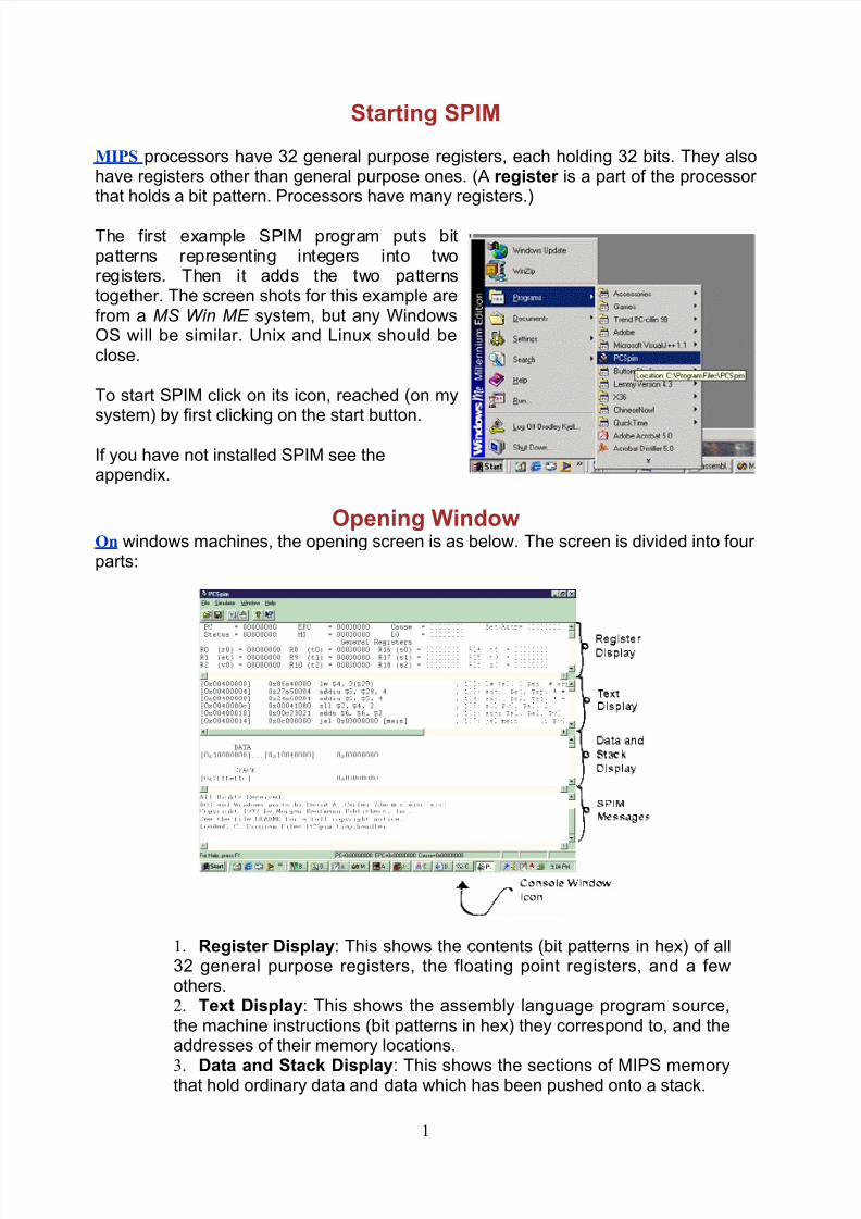
To start SPIM click on its icon, reached (on mysystem) by first clicking on the start button.
If you have not installed SPIM see theappendix.
Opening WindowOn windows machines, the opening screen is as below. The screen is divided into four parts:
1. Register Display: This shows the contents (bit patterns in hex) of all32 general purpose registers, the floating point registers, and a fewothers.2. Text Display: This shows the assembly language program source,the machine instructions (bit patterns in hex) they correspond to, and theaddresses of their memory locations.
3. Data and Stack Display: This shows the sections of MIPS memorythat hold ordinary data and data which has been pushed onto a stack.
1
8/4/2019 Spim Lab Manual
http://slidepdf.com/reader/full/spim-lab-manual 2/26
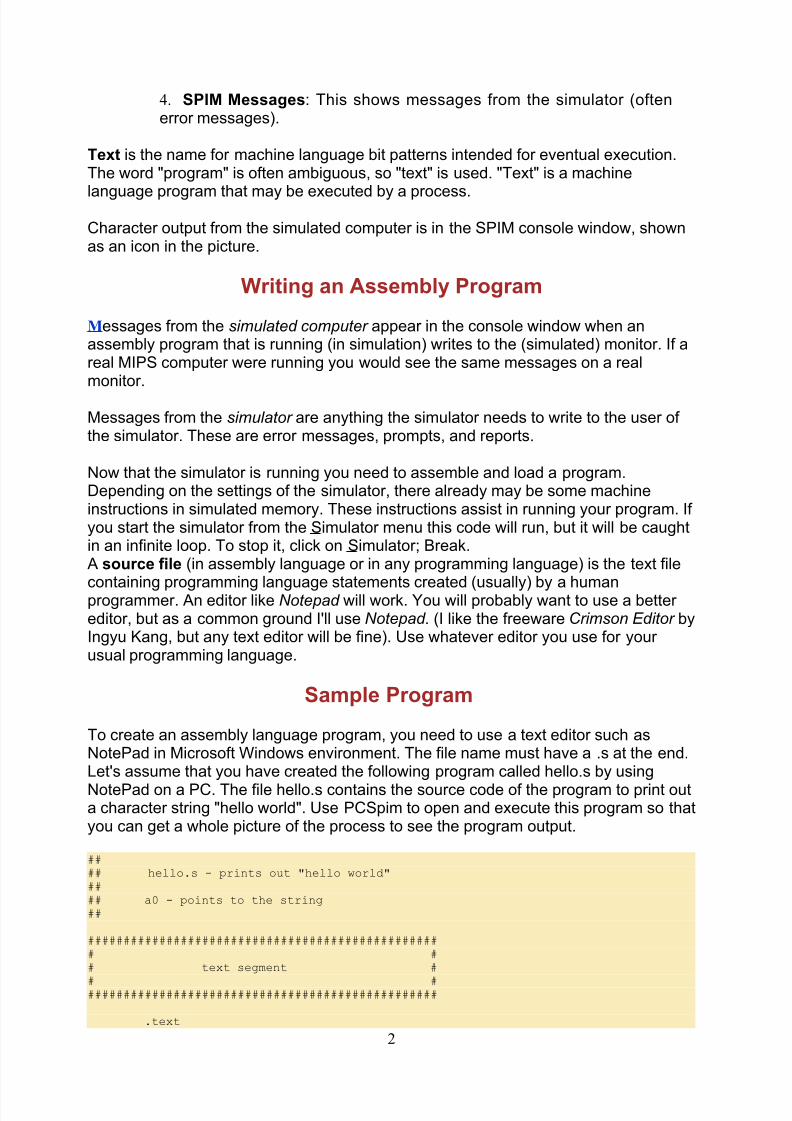
4. SPIM Messages: This shows messages from the simulator (oftenerror messages).
Text is the name for machine language bit patterns intended for eventual execution.The word "program" is often ambiguous, so "text" is used. "Text" is a machine
language program that may be executed by a process.
Character output from the simulated computer is in the SPIM console window, shownas an icon in the picture.
Writing an Assembly Program
Messages from the simulated computer appear in the console window when anassembly program that is running (in simulation) writes to the (simulated) monitor. If areal MIPS computer were running you would see the same messages on a realmonitor.
Messages from the simulator are anything the simulator needs to write to the user of the simulator. These are error messages, prompts, and reports.
Now that the simulator is running you need to assemble and load a program.Depending on the settings of the simulator, there already may be some machineinstructions in simulated memory. These instructions assist in running your program. If you start the simulator from the Simulator menu this code will run, but it will be caughtin an infinite loop. To stop it, click on Simulator; Break.A source file (in assembly language or in any programming language) is the text file
containing programming language statements created (usually) by a humanprogrammer. An editor like Notepad will work. You will probably want to use a better editor, but as a common ground I'll use Notepad . (I like the freeware Crimson Editor byIngyu Kang, but any text editor will be fine). Use whatever editor you use for your usual programming language.
Sample Program
To create an assembly language program, you need to use a text editor such asNotePad in Microsoft Windows environment. The file name must have a .s at the end.Let's assume that you have created the following program called hello.s by using
NotePad on a PC. The file hello.s contains the source code of the program to print outa character string "hello world". Use PCSpim to open and execute this program so thatyou can get a whole picture of the process to see the program output.
#### hello.s - prints out "hello world"#### a0 - points to the string##
################################################## ## text segment #
# ##################################################
.text
2
8/4/2019 Spim Lab Manual
http://slidepdf.com/reader/full/spim-lab-manual 3/26
.globl __start__start: # execution starts here
la $a0,str # put string address into a0li $v0,4 # system call to printsyscall # out a string
li $v0,10 # Exitsyscall # Bye!
################################################## ## data segment ## ##################################################
.datastr: .asciiz "hello world\n"
#### end of file hello.s
Word processors usually create "binary" files and so are not suitable for creatingsource files. They can be forced to output a text file, but a real programming editor ismuch nicer. With your program (text) editor create a file called addup.asm. (With mosttext editors and Web browsers you can copy the following code from the Web pageand then paste into the editor).
## Program to add two plus three.text.globl main
main:
ori $8,$0,0x2 # put two's comp. two into register 8ori $9,$0,0x3 # put two's comp. three into register 9addu $10,$8,$9 # add register 8 and 9, put result in 10
## End of file
The first "#" of the first line is in column one. The character "#" starts a comment;everything on the line from "#" to the right is ignored. Sometimes I use two in a row for emphasis, but only one is needed.
Each of the three lines following main: corresponds to one machine instruction.
Setting up SPIM
A machine instruction is a pattern of bits that asks for one machine operation to beexecuted.
Each MIPS machine instruction is 32 bits (four bytes) long. The three lines after main:call for three machine instructions. The remaining lines consist of information for theassembler and comments (for the human).
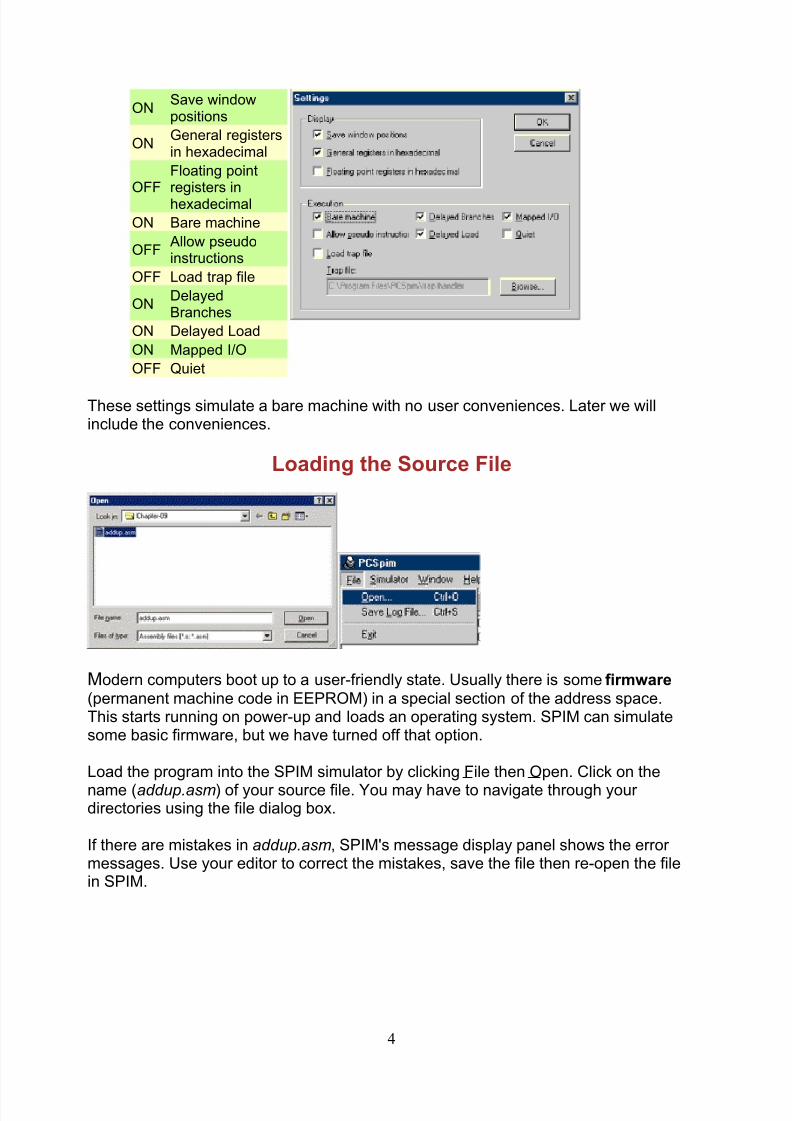
For this first program some SPIM options must be set. In the menu bar, click on
Simulator then Settings to get the settings dialog. Select the following options:
3
8/4/2019 Spim Lab Manual
http://slidepdf.com/reader/full/spim-lab-manual 4/26
ONSave windowpositions
ONGeneral registersin hexadecimal
OFFFloating pointregisters inhexadecimal
ON Bare machine
OFFAllow pseudoinstructions
OFF Load trap file
ONDelayedBranches
ON Delayed Load
ON Mapped I/O
OFF Quiet
These settings simulate a bare machine with no user conveniences. Later we willinclude the conveniences.
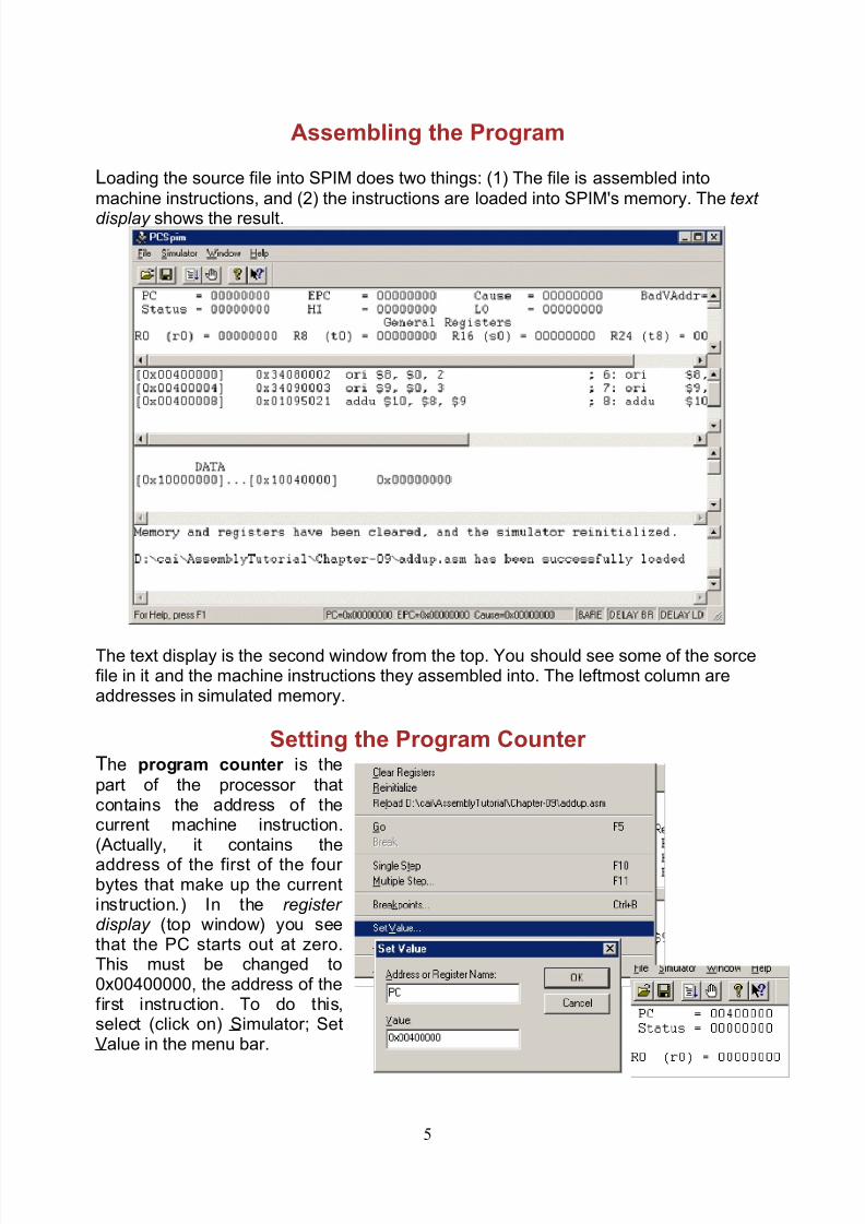
Loading the Source File
Modern computers boot up to a user-friendly state. Usually there is some firmware(permanent machine code in EEPROM) in a special section of the address space.This starts running on power-up and loads an operating system. SPIM can simulatesome basic firmware, but we have turned off that option.
Load the program into the SPIM simulator by clicking File then Open. Click on the
name (addup.asm) of your source file. You may have to navigate through your directories using the file dialog box.
If there are mistakes in addup.asm, SPIM's message display panel shows the error messages. Use your editor to correct the mistakes, save the file then re-open the filein SPIM.
4
8/4/2019 Spim Lab Manual
http://slidepdf.com/reader/full/spim-lab-manual 5/26
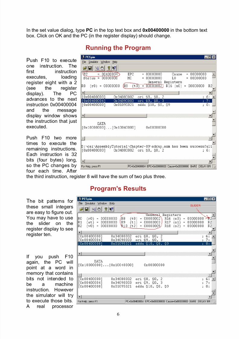
Assembling the Program
Loading the source file into SPIM does two things: (1) The file is assembled intomachine instructions, and (2) the instructions are loaded into SPIM's memory. The text
display shows the result.
The text display is the second window from the top. You should see some of the sorcefile in it and the machine instructions they assembled into. The leftmost column areaddresses in simulated memory.
Setting the Program Counter The program counter is thepart of the processor thatcontains the address of thecurrent machine instruction.(Actually, it contains theaddress of the first of the four bytes that make up the currentinstruction.) In the register display (top window) you seethat the PC starts out at zero.This must be changed to0x00400000, the address of thefirst instruction. To do this,select (click on) Simulator; SetValue in the menu bar.
5
8/4/2019 Spim Lab Manual
http://slidepdf.com/reader/full/spim-lab-manual 6/26
In the set value dialog, type PC in the top text box and 0x00400000 in the bottom textbox. Click on OK and the PC (in the register display) should change.
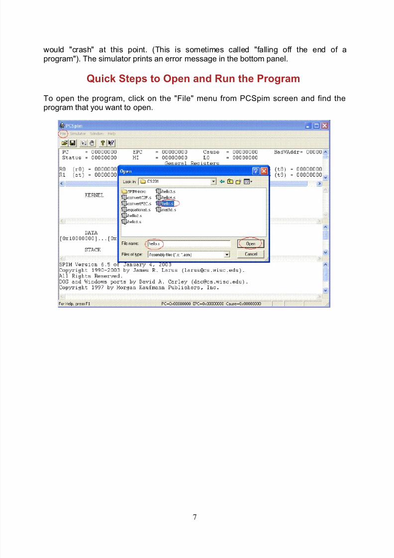
Running the Program
Push F10 to executeone instruction. Thefirst instructionexecutes, loadingregister eight with a 2(see the register display). The PCadvances to the nextinstruction 0x00400004and the messagedisplay window showsthe instruction that justexecuted.
Push F10 two moretimes to execute theremaining instructions.Each instruction is 32bits (four bytes) long,so the PC changes byfour each time. After
the third instruction, register 8 will have the sum of two plus three.
Program's Results
The bit patterns for these small integersare easy to figure out.You may have to usethe slider on theregister display to seeregister ten.
If you push F10again, the PC willpoint at a word inmemory that containsbits not intended tobe a machineinstruction. However
the simulator will tryto execute those bits.A real processor
6
8/4/2019 Spim Lab Manual
http://slidepdf.com/reader/full/spim-lab-manual 7/26
would "crash" at this point. (This is sometimes called "falling off the end of aprogram"). The simulator prints an error message in the bottom panel.
Quick Steps to Open and Run the Program
To open the program, click on the "File" menu from PCSpim screen and find theprogram that you want to open.
7
8/4/2019 Spim Lab Manual
http://slidepdf.com/reader/full/spim-lab-manual 8/26
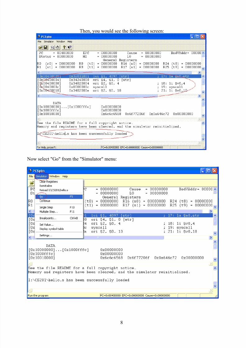
Then, you would see the following screen:
Now select "Go" from the "Simulator" menu:
8

8/4/2019 Spim Lab Manual
http://slidepdf.com/reader/full/spim-lab-manual 9/26
To run the program, click on "OK".
Here is the program output on the "Console".
Explanation of the ProgramThe MIPS assembly language program using PCSpim is usually held in a file with .s at the endof the file name.For example hello.s. This file is processed line by line by the SPIM program. In this file,
A sharp sign # is used to begin inline comments.i.e. Everything from the # to the end of the line is
ignored by the assembler.
An identifier is a sequence of alphanumeric characters,underbars/underscores(_),and dots(.) that do not begin with a number.
A label is declared by putting identifiers at the beginning of a linefollowed by a colon. For example: str:
9
8/4/2019 Spim Lab Manual
http://slidepdf.com/reader/full/spim-lab-manual 10/26
An operation field contains either a machine instruction oran assembler directive.
One or more operands are required by some machine instructions.Assembler directives may also require operands.
A constant is a value that does not change during program assembly
or execution. A string contant is delimited by double quotes(").For example: "Hello World\n"
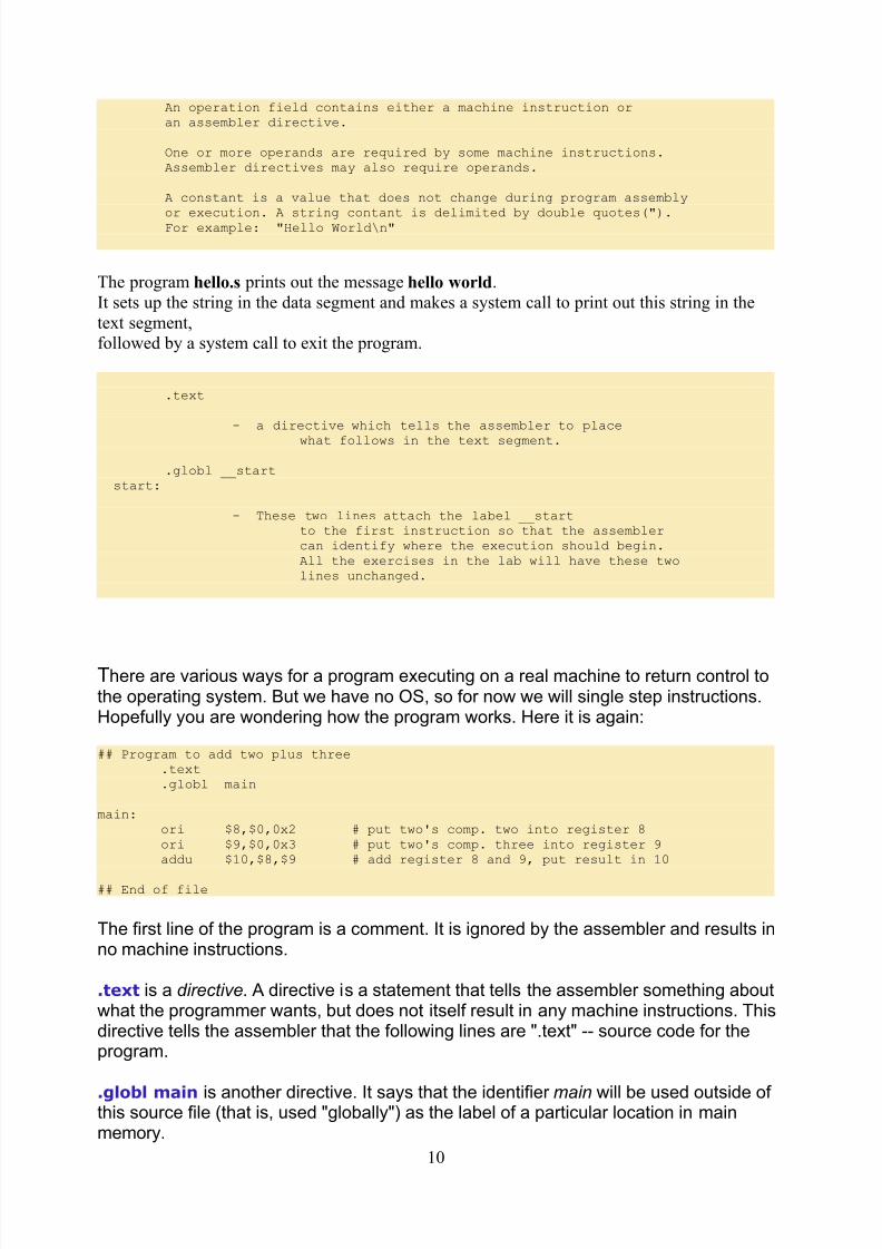
The program hello.s prints out the message hello world.It sets up the string in the data segment and makes a system call to print out this string in thetext segment,followed by a system call to exit the program.
.text
- a directive which tells the assembler to place
what follows in the text segment.
.globl __start__start:
- These two lines attach the label __startto the first instruction so that the assemblercan identify where the execution should begin.All the exercises in the lab will have these twolines unchanged.
There are various ways for a program executing on a real machine to return control tothe operating system. But we have no OS, so for now we will single step instructions.Hopefully you are wondering how the program works. Here it is again:
## Program to add two plus three.text.globl main
main:ori $8,$0,0x2 # put two's comp. two into register 8ori $9,$0,0x3 # put two's comp. three into register 9addu $10,$8,$9 # add register 8 and 9, put result in 10
## End of file
The first line of the program is a comment. It is ignored by the assembler and results inno machine instructions.
.text is a directive. A directive is a statement that tells the assembler something aboutwhat the programmer wants, but does not itself result in any machine instructions. Thisdirective tells the assembler that the following lines are ".text" -- source code for theprogram.
.globl main is another directive. It says that the identifier main will be used outside of this source file (that is, used "globally") as the label of a particular location in mainmemory.
10
8/4/2019 Spim Lab Manual
http://slidepdf.com/reader/full/spim-lab-manual 11/26
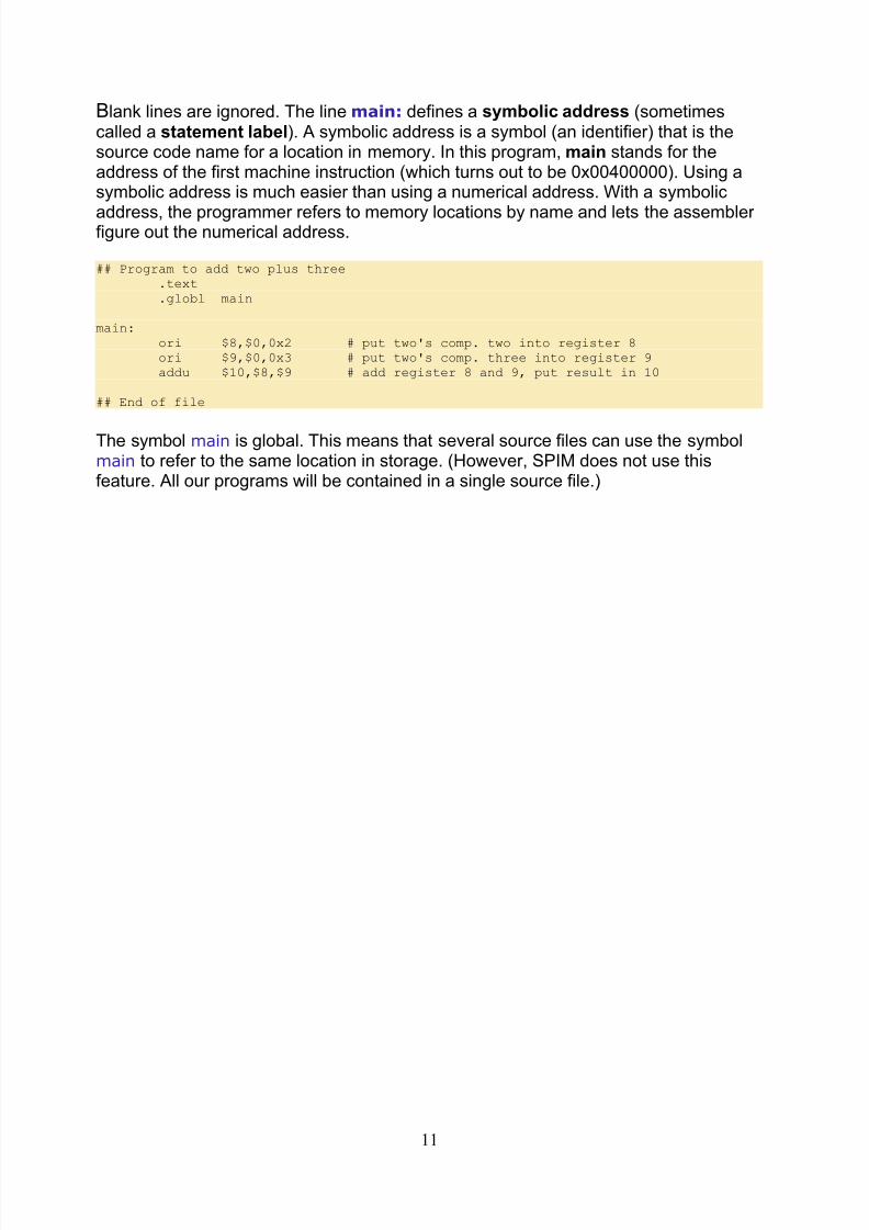
Blank lines are ignored. The line main: defines a symbolic address (sometimescalled a statement label). A symbolic address is a symbol (an identifier) that is thesource code name for a location in memory. In this program, main stands for theaddress of the first machine instruction (which turns out to be 0x00400000). Using asymbolic address is much easier than using a numerical address. With a symbolic
address, the programmer refers to memory locations by name and lets the assembler figure out the numerical address.
## Program to add two plus three.text.globl main
main:ori $8,$0,0x2 # put two's comp. two into register 8ori $9,$0,0x3 # put two's comp. three into register 9addu $10,$8,$9 # add register 8 and 9, put result in 10
## End of file
The symbol main is global. This means that several source files can use the symbolmain to refer to the same location in storage. (However, SPIM does not use thisfeature. All our programs will be contained in a single source file.)
11
8/4/2019 Spim Lab Manual
http://slidepdf.com/reader/full/spim-lab-manual 12/26
8/4/2019 Spim Lab Manual
http://slidepdf.com/reader/full/spim-lab-manual 13/26
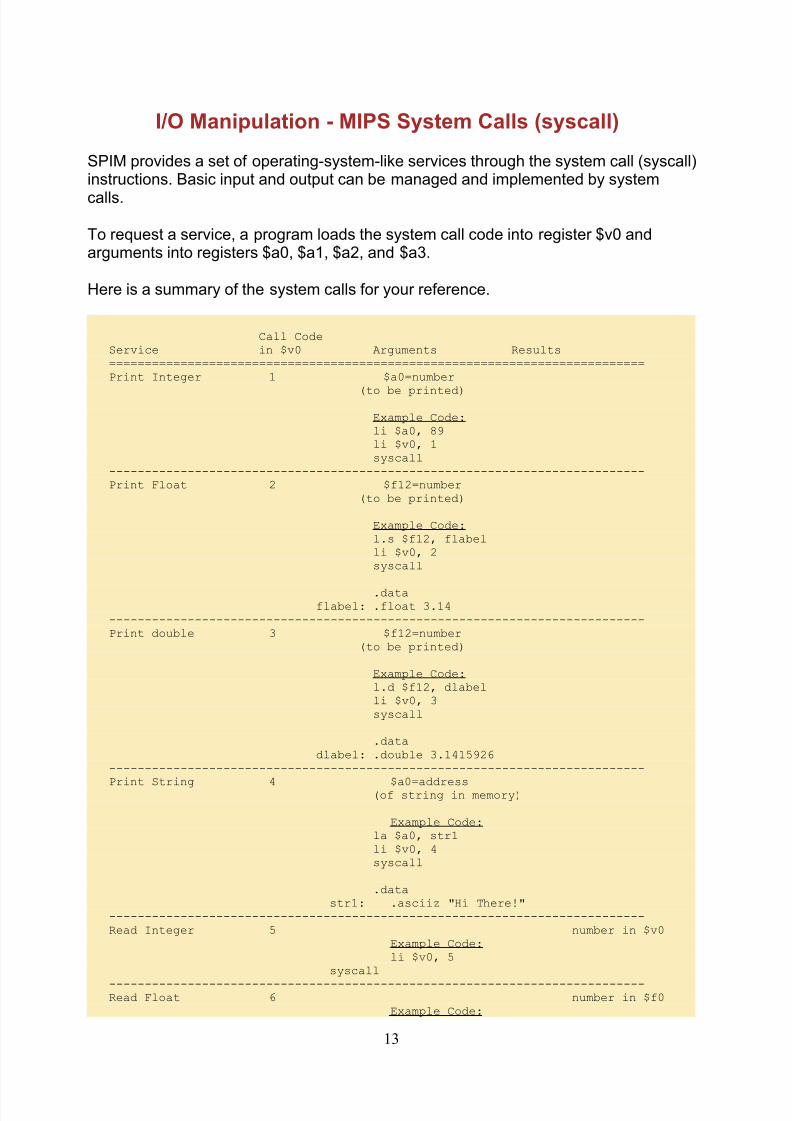
I/O Manipulation - MIPS System Calls (syscall)
SPIM provides a set of operating-system-like services through the system call (syscall)instructions. Basic input and output can be managed and implemented by system
calls.
To request a service, a program loads the system call code into register $v0 andarguments into registers $a0, $a1, $a2, and $a3.
Here is a summary of the system calls for your reference.
Call CodeService in $v0 Arguments Results===========================================================================Print Integer 1 $a0=number
(to be printed)
Example Code:li $a0, 89li $v0, 1syscall
---------------------------------------------------------------------------Print Float 2 $f12=number
(to be printed)
Example Code:l.s $f12, flabelli $v0, 2syscall
.dataflabel: .float 3.14
---------------------------------------------------------------------------Print double 3 $f12=number
(to be printed)
Example Code:l.d $f12, dlabelli $v0, 3syscall
.datadlabel: .double 3.1415926
---------------------------------------------------------------------------
Print String 4 $a0=address(of string in memory)
Example Code:la $a0, str1li $v0, 4syscall
.datastr1: .asciiz "Hi There!"
---------------------------------------------------------------------------Read Integer 5 number in $v0
Example Code:li $v0, 5
syscall
---------------------------------------------------------------------------Read Float 6 number in $f0
Example Code:
13

8/4/2019 Spim Lab Manual
http://slidepdf.com/reader/full/spim-lab-manual 14/26
li $v0, 6syscall
---------------------------------------------------------------------------Read double 7 number in $f0
Example Code:li $v0, 7
syscall
---------------------------------------------------------------------------Read String 8 $a0=address(of input string in memory)
$a1=length of buffer(n bytes)
Example Code:la $a0, str1
li $a1, 80li $v0, 8syscall
.datastr1: .space 80
---------------------------------------------------------------------------Sbrk 9 $a0=n-byte address in $v0
(Dynamically (to allocate)allocate n-byteof memory) Example Code:
li $a0, 80li $v0, 9syscall # Get memory
move $a0, $v0li $a1, 80li $v0, 8syscall # Read Stringli $v0, 4syscall # Print String
---------------------------------------------------------------------------Exit 10 Example Code:
li $v0, 10syscall
---------------------------------------------------------------------------
A Few Special Characters
Character Escape=======================Newline \n
Tab \tDouble Quote \"
14
8/4/2019 Spim Lab Manual
http://slidepdf.com/reader/full/spim-lab-manual 15/26
Memory Model
Modern computer systems nearly always use cache memory and virtual memory.
But our abstract view of memory does not include them. The purpose of virtualmemory is to make it appear as if a program has the full address space available. Soour programming model has the full address space. The purpose of cache is totransparently speed up memory access. So our programming model does not includecache. Memory in the programming model is as follows:
DATA:
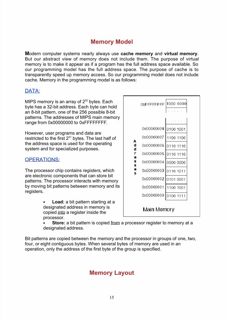
MIPS memory is an array of 232 bytes. Eachbyte has a 32-bit address. Each byte can hold
an 8-bit pattern, one of the 256 possible 8-bitpatterns. The addresses of MIPS main memoryrange from 0x00000000 to 0xFFFFFFFF.
However, user programs and data arerestricted to the first 231 bytes. The last half of the address space is used for the operatingsystem and for specialized purposes.
OPERATIONS:
The processor chip contains registers, whichare electronic components that can store bitpatterns. The processor interacts with memoryby moving bit patterns between memory and itsregisters.
• Load: a bit pattern starting at adesignated address in memory iscopied into a register inside theprocessor.•
Store: a bit pattern is copied from a processor register to memory at adesignated address.
Bit patterns are copied between the memory and the processor in groups of one, two,four, or eight contiguous bytes. When several bytes of memory are used in anoperation, only the address of the first byte of the group is specified.
Memory Layout
15
8/4/2019 Spim Lab Manual
http://slidepdf.com/reader/full/spim-lab-manual 16/26
Load and store operations copy the bit pattern from the source into the destination.The source (register or memory) does not change. Of course, the pattern at thedestination is replaced by the pattern at the source.
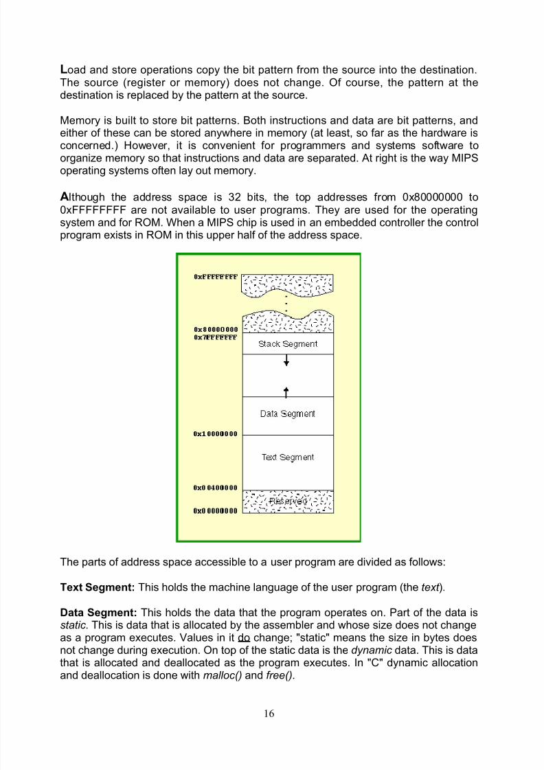
Memory is built to store bit patterns. Both instructions and data are bit patterns, and
either of these can be stored anywhere in memory (at least, so far as the hardware isconcerned.) However, it is convenient for programmers and systems software toorganize memory so that instructions and data are separated. At right is the way MIPSoperating systems often lay out memory.
Although the address space is 32 bits, the top addresses from 0x80000000 to0xFFFFFFFF are not available to user programs. They are used for the operatingsystem and for ROM. When a MIPS chip is used in an embedded controller the controlprogram exists in ROM in this upper half of the address space.
The parts of address space accessible to a user program are divided as follows:
Text Segment: This holds the machine language of the user program (the text ).
Data Segment: This holds the data that the program operates on. Part of the data isstatic . This is data that is allocated by the assembler and whose size does not changeas a program executes. Values in it do change; "static" means the size in bytes doesnot change during execution. On top of the static data is the dynamic data. This is datathat is allocated and deallocated as the program executes. In "C" dynamic allocation
and deallocation is done with malloc() and free().
16
8/4/2019 Spim Lab Manual
http://slidepdf.com/reader/full/spim-lab-manual 17/26
Stack Segment: At the top of user address space is the stack. With high levellanguages, local variables and parameters are pushed and popped on the stack asprocedures are activated and deactivated.
Registers
Often data consist of several contiguous bytes. Each computer manufacturer has itsown idea of what to call groupings larger than a byte. The following is used for MIPSchips.
• byte — eight bits.• word — four bytes, 32 bits.• double word — eight bytes, 64 bits.
A block of contiguous memory is referred to by the address of its first byte (ie. the bytewith the lowest address.) Most MIPS instructions involve a fixed number of bytes.
Often you need a number of bits other than one of the standard amounts. Use the nextlarger standard amount, and remember to be careful. Attempting to use the veryminimum number of bits is more complicated than it is worth and is a rich source of errors in assembly language programming.
A register is a part of the processor that can hold a bit pattern. On the MIPS, aregister holds 32 bits. There are many registers in the processor, but only some of them are visible in assembly language. The others are used by the processor incarrying out its operations.
• A load operation copies a bit pattern from memory into a register.• A store operation copies a bit pattern from a register into memory.
The registers that are visible in assembly language are called general purposeregisters and floating point registers. There are 32 general purpose registers. Eachgeneral purpose register holds a 32 bit pattern. In assembly language, these registersare named $0, $1, $2, ... , $31. There are 32 floating point registers. These arediscussed in a later chapter.
One of the general purpose registers is hard-wired to always contain the value
0x00000000 (all zero bits).
Registers and the ALU
The arithmetic/logic unit (ALU) of a processor performs integer arithmetic andlogical operations. For example, one of its operations is to add two 32-bit integers. Aninteger used as input to an operation is called an operand. One operand for the ALUis always contained in a register. The other operand may be in a register or may bepart of the machine instruction itself. The result of the operation is put into a generalpurpose register.
17
8/4/2019 Spim Lab Manual
http://slidepdf.com/reader/full/spim-lab-manual 18/26
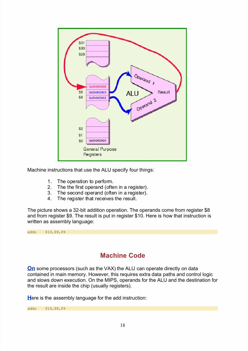
Machine instructions that use the ALU specify four things:
1. The operation to perform.2. The the first operand (often in a register).3. The second operand (often in a register).4. The register that receives the result.
The picture shows a 32-bit addition operation. The operands come from register $8and from register $9. The result is put in register $10. Here is how that instruction iswritten as assembly language:
addu $10,$8,$9
Machine Code
On some processors (such as the VAX) the ALU can operate directly on datacontained in main memory. However, this requires extra data paths and control logicand slows down execution. On the MIPS, operands for the ALU and the destination for the result are inside the chip (usually registers).
Here is the assembly language for the add instruction:
addu $10,$8,$9
18
8/4/2019 Spim Lab Manual
http://slidepdf.com/reader/full/spim-lab-manual 19/26
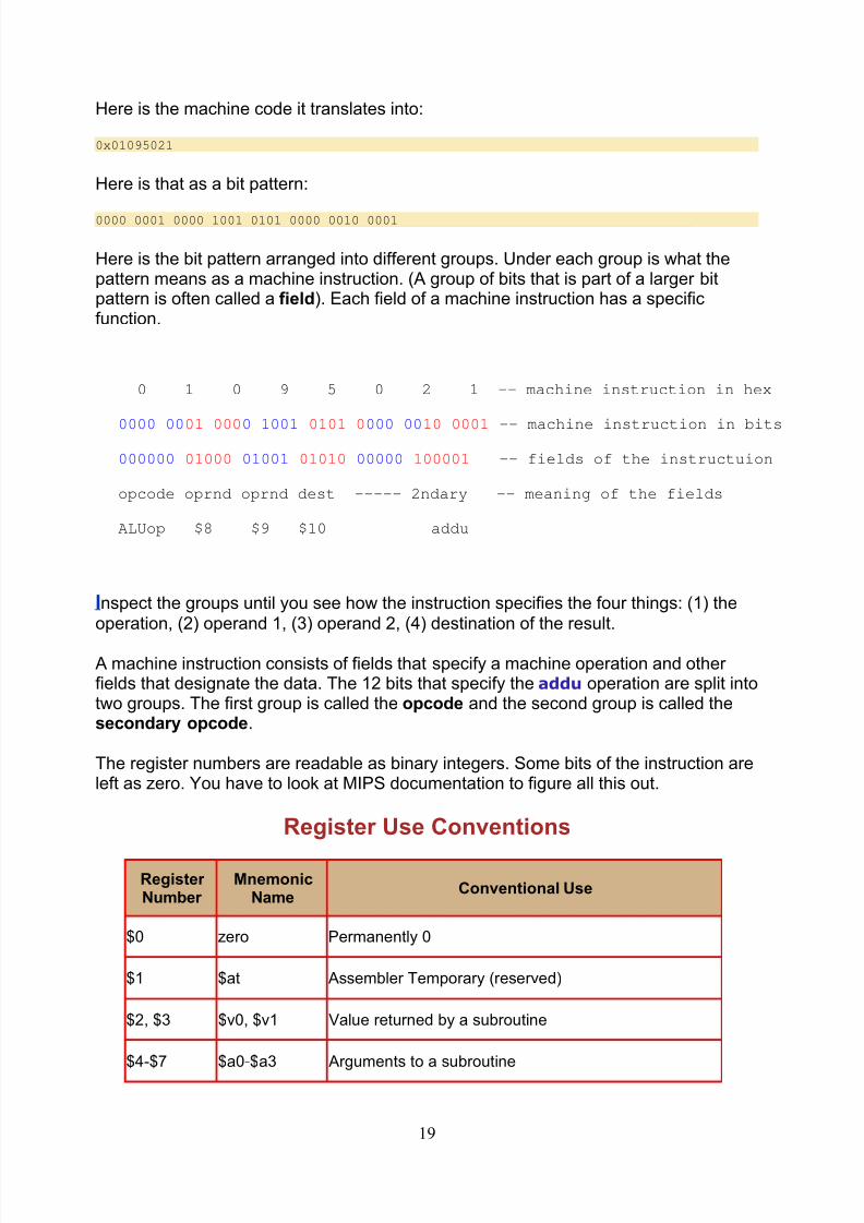
Here is the machine code it translates into:
0x01095021
Here is that as a bit pattern:
0000 0001 0000 1001 0101 0000 0010 0001
Here is the bit pattern arranged into different groups. Under each group is what thepattern means as a machine instruction. (A group of bits that is part of a larger bitpattern is often called a field). Each field of a machine instruction has a specificfunction.
0 1 0 9 5 0 2 1 -- machine instruction in hex
0000 0001 0000 1001 0101 0000 0010 0001 -- machine instruction in bits
000000 01000 01001 01010 00000 100001 -- fields of the instructuion
opcode oprnd oprnd dest ----- 2ndary -- meaning of the fields
ALUop $8 $9 $10 addu
Inspect the groups until you see how the instruction specifies the four things: (1) theoperation, (2) operand 1, (3) operand 2, (4) destination of the result.
A machine instruction consists of fields that specify a machine operation and other fields that designate the data. The 12 bits that specify the addu operation are split intotwo groups. The first group is called the opcode and the second group is called thesecondary opcode.
The register numbers are readable as binary integers. Some bits of the instruction areleft as zero. You have to look at MIPS documentation to figure all this out.
Register Use Conventions
Register Number
MnemonicName
Conventional Use
$0 zero Permanently 0
$1 $at Assembler Temporary (reserved)
$2, $3 $v0, $v1 Value returned by a subroutine
$4-$7 $a0-$a3 Arguments to a subroutine
19
8/4/2019 Spim Lab Manual
http://slidepdf.com/reader/full/spim-lab-manual 20/26
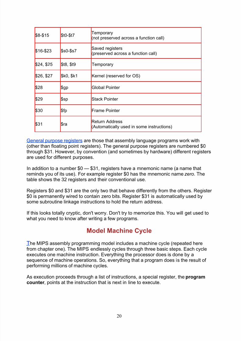
$8-$15 $t0-$t7Temporary(not preserved across a function call)
$16-$23 $s0-$s7Saved registers(preserved across a function call)
$24, $25 $t8, $t9 Temporary
$26, $27 $k0, $k1 Kernel (reserved for OS)
$28 $gp Global Pointer
$29 $sp Stack Pointer
$30 $fp Frame Pointer
$31 $raReturn Address(Automatically used in some instructions)
General purpose registers are those that assembly language programs work with(other than floating point registers). The general purpose registers are numbered $0through $31. However, by convention (and sometimes by hardware) different registersare used for different purposes.
In addition to a number $0 — $31, registers have a mnemonic name (a name thatreminds you of its use). For example register $0 has the mnemonic name zero. The
table shows the 32 registers and their conventional use.
Registers $0 and $31 are the only two that behave differently from the others. Register $0 is permanently wired to contain zero bits. Register $31 is automatically used bysome subroutine linkage instructions to hold the return address.
If this looks totally cryptic, don't worry. Don't try to memorize this. You will get used towhat you need to know after writing a few programs.
Model Machine Cycle
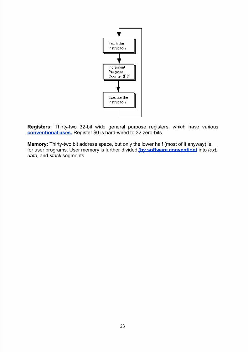
The MIPS assembly programming model includes a machine cycle (repeated herefrom chapter one). The MIPS endlessly cycles through three basic steps. Each cycleexecutes one machine instruction. Everything the processor does is done by asequence of machine operations. So, everything that a program does is the result of performing millions of machine cycles.
As execution proceeds through a list of instructions, a special register, the programcounter , points at the instruction that is next in line to execute.
20

8/4/2019 Spim Lab Manual
http://slidepdf.com/reader/full/spim-lab-manual 21/26
Fetch the next Instruction. The program counter contains the address of the nextmachine instruction. The instruction is fetched from memory.Increment the PC. The address in the program counter is incremented by four.Execute the Instruction. The machine operation specified by the instruction isperformed.
Sequential Execution
MIPS machine instructions are all 32 bits wide (4 bytes). Normally, instructions are
executed one after another starting with the first instruction of the program andproceeding upward through memory. The execution sequence can be changed with abranch or a jump machine instruction.
Here, for example, is the program from the previous chapter. The three machineinstructions have been placed at locations 0x00400000, 0x00400004, and0x00400008, and are executed in that order.
It would take three machine cycles to execute this very tiny program.
Control
Any bit pattern that is fetched as an instruction by the machine cycle is interpreted asan instruction. The bit patterns in the fields tell the electronics what operation toperform and what data to use. If the bit pattern makes no sense as an instruction thenthe machine cycle is interrupted. This causes the program to "crash" (or to "bomb".)
However, if the pattern can be interpreted as an instruction then it will be executed,whatever it does.
21
8/4/2019 Spim Lab Manual
http://slidepdf.com/reader/full/spim-lab-manual 22/26
The control point of an executing program is the address in memory of the instructionbeing executed. When an instruction is being executed (in the third step of themachine cycle) the program counter holds the address of the instruction after thecontrol point.
Normally the control point moves sequentially through the machine instructions. Onthe MIPS this means it normally moves through memory in steps of four bytes (32 bits)at a time. Usually "control point" is shortened to "control" and the phrase flow of control means how the control point moves through memory.
If control flow leads to an address in memory, then the four bytes starting at thataddress are fetched as a machine instruction. The processor has no other way to tellinstructions from data. Whatever bit pattern gets pulled in from memory as aninstruction will be executed as an instruction. It is common for the control point of abuggy program to enter a section of data. This sometimes leads to mystifying results.
By software convention, data and instructions are placed in different sections of memory. (This helps prevent mystifying results). But this is not a requirement of thearchitecture.
Multitasking
With Microsoft's DOS, programs were passed control, ran until completion, thenpassed control back to DOS. So only one application ran at a time. Worse, anapplication that messed up might never return control to DOS and the whole systemwould freeze.
Modern computer systems include features that can interrupt the control flow of anexecuting program. After the flow is interrupted, the operating system can give controlto another application. If this is done many times a second the computer systemappears to be simultaneously executing several applications. This trick is calledmultitasking. It has been used from about 1960 for mainframes, from 1978 for manymicrocomputers, and from about 1995 for Windows PCs.
The MIPS chip has very good support for multitasking. But this is an advanced topicnot included in our basic programming model.
Model Summary
Here is a summary of the basic MIPS programming model. Click on the hyperlinks for more details.
Machine Instructions: Machine instructions are thirty-two bits wide. Bit patternsspecify the operation, the operands, and the destination for the result. Basicoperations are arithmetic, logic, memory access, and control branches.
Machine Cycle: The machine cycle is illustrated at right. Execution proceeds
sequentially one instruction at a time. The control point indicates the instructionabout to execute. ALU operations never directly access memory.
22
8/4/2019 Spim Lab Manual
http://slidepdf.com/reader/full/spim-lab-manual 23/26
Registers: Thirty-two 32-bit wide general purpose registers, which have variousconventional uses. Register $0 is hard-wired to 32 zero-bits.
Memory: Thirty-two bit address space, but only the lower half (most of it anyway) isfor user programs. User memory is further divided (by software convention) into text ,data, and stack segments.
23
8/4/2019 Spim Lab Manual
http://slidepdf.com/reader/full/spim-lab-manual 24/26
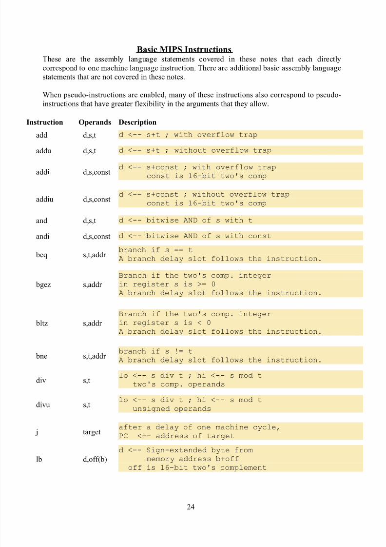
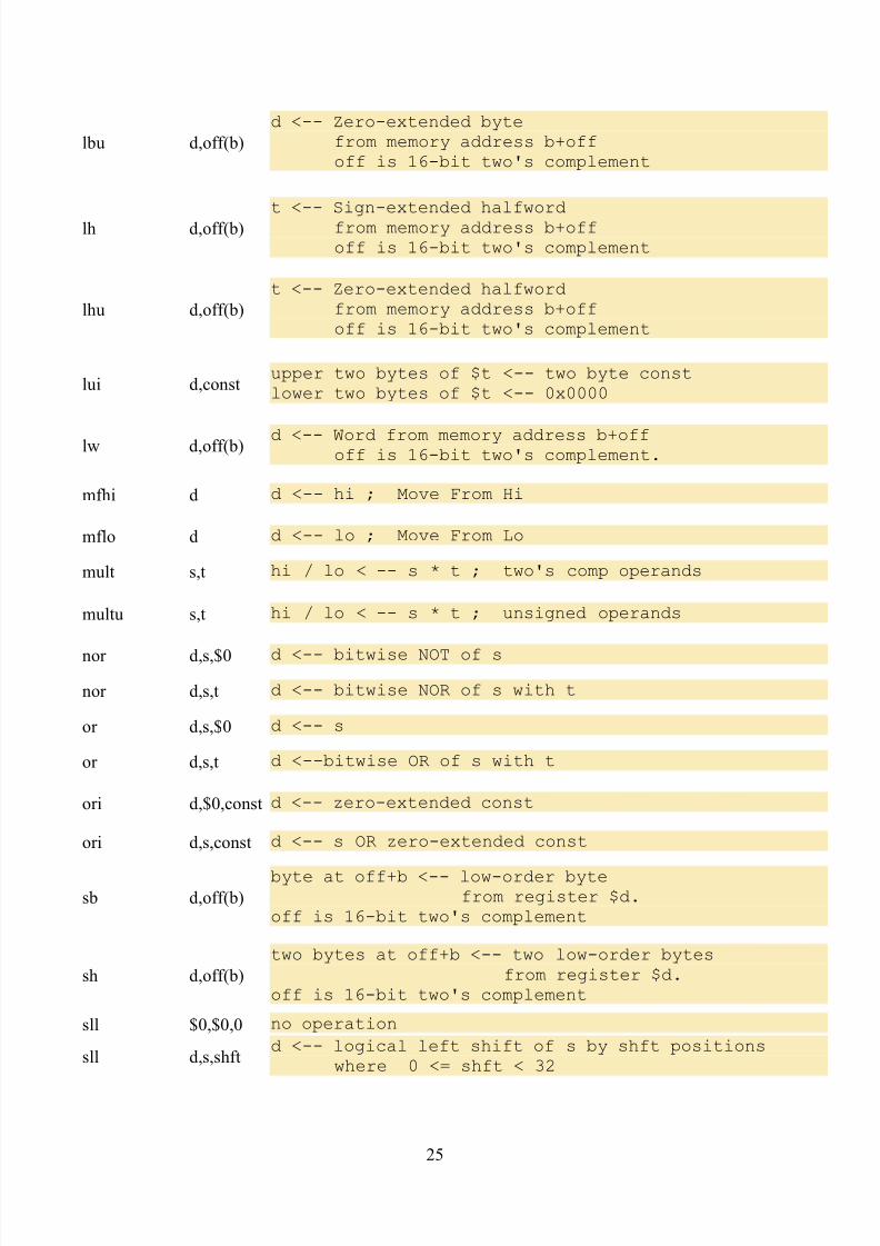
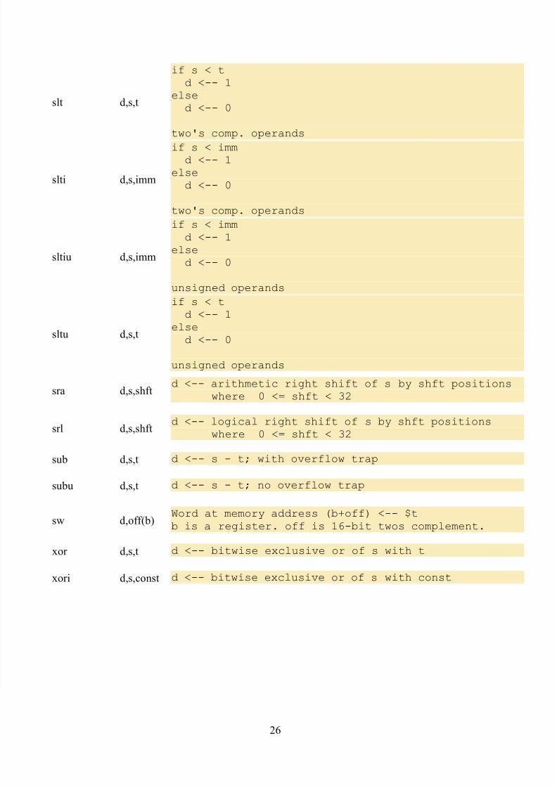
Basic MIPS InstructionsThese are the assembly language statements covered in these notes that each directlycorrespond to one machine language instruction. There are additional basic assembly languagestatements that are not covered in these notes.
When pseudo-instructions are enabled, many of these instructions also correspond to pseudo-instructions that have greater flexibility in the arguments that they allow.
Instruction Operands Description
add d,s,t d <-- s+t ; with overflow trap
addu d,s,t d <-- s+t ; without overflow trap
addi d,s,constd <-- s+const ; with overflow trap
const is 16-bit two's comp
addiu d,s,constd <-- s+const ; without overflow trap
const is 16-bit two's comp
and d,s,t d <-- bitwise AND of s with t
andi d,s,const d <-- bitwise AND of s with const
beq s,t,addr branch if s == tA branch delay slot follows the instruction.
bgez s,addr
Branch if the two's comp. integer
in register s is >= 0A branch delay slot follows the instruction.
bltz s,addr
Branch if the two's comp. integerin register s is < 0A branch delay slot follows the instruction.
bne s,t,addr branch if s != tA branch delay slot follows the instruction.
div s,t
lo <-- s div t ; hi <-- s mod t
two's comp. operands
divu s,tlo <-- s div t ; hi <-- s mod t
unsigned operands
j targetafter a delay of one machine cycle,PC <-- address of target
lb d,off(b)
d <-- Sign-extended byte frommemory address b+off
off is 16-bit two's complement
24
8/4/2019 Spim Lab Manual
http://slidepdf.com/reader/full/spim-lab-manual 25/26
lbu d,off(b)
d <-- Zero-extended bytefrom memory address b+offoff is 16-bit two's complement
lh d,off(b)
t <-- Sign-extended halfwordfrom memory address b+offoff is 16-bit two's complement
lhu d,off(b)
t <-- Zero-extended halfwordfrom memory address b+offoff is 16-bit two's complement
lui d,constupper two bytes of $t <-- two byte constlower two bytes of $t <-- 0x0000
lw d,off(b) d <-- Word from memory address b+offoff is 16-bit two's complement.
mfhi d d <-- hi ; Move From Hi
mflo d d <-- lo ; Move From Lo
mult s,t hi / lo < -- s * t ; two's comp operands
multu s,t hi / lo < -- s * t ; unsigned operands
nor d,s,$0 d <-- bitwise NOT of s
nor d,s,t d <-- bitwise NOR of s with t
or d,s,$0 d <-- s
or d,s,t d <--bitwise OR of s with t
ori d,$0,const d <-- zero-extended const
ori d,s,const d <-- s OR zero-extended const
sb d,off(b)byte at off+b <-- low-order byte
from register $d.off is 16-bit two's complement
sh d,off(b)
two bytes at off+b <-- two low-order bytesfrom register $d.
off is 16-bit two's complement
sll $0,$0,0 no operation
sll d,s,shftd <-- logical left shift of s by shft positions
where 0 <= shft < 32
25
8/4/2019 Spim Lab Manual
http://slidepdf.com/reader/full/spim-lab-manual 26/26
slt d,s,t
if s < td <-- 1
elsed <-- 0
two's comp. operands
slti d,s,imm
if s < immd <-- 1
elsed <-- 0
two's comp. operands
sltiu d,s,imm
if s < immd <-- 1
elsed <-- 0
unsigned operands
sltu d,s,t
if s < td <-- 1
elsed <-- 0
unsigned operands
sra d,s,shftd <-- arithmetic right shift of s by shft positions
where 0 <= shft < 32
srl d,s,shftd <-- logical right shift of s by shft positions
where 0 <= shft < 32
sub d,s,t d <-- s - t; with overflow trap
subu d,s,t d <-- s - t; no overflow trap
sw d,off(b)Word at memory address (b+off) <-- $tb is a register. off is 16-bit twos complement.
xor d,s,t d <-- bitwise exclusive or of s with t
xori d,s,const d <-- bitwise exclusive or of s with const


![Lidialetykarina pczombie,spim,ramsonware[1]](https://static.fdocuments.net/doc/165x107/55b4a040bb61ebaf168b4824/lidialetykarina-pczombiespimramsonware1.jpg)