Spent Fuel Storage and Transportation of Accident Tolerant ...
64
Choose an item. PNNL- 30451 Spent Fuel Storage and Transportation of Accident Tolerant Fuel Concepts Cr-Coated Zirconium Alloy and FeCrAl Cladding September 2020 Joseph M Brusky Kenneth J Geelhood Christine E Goodson Walter G Luscher Prepared for the U.S. Nuclear Regulatory Commission Office of Nuclear Regulatory Research Under Contract DE-AC05-76RL01830 Interagency Agreement: NRC-HQ-25-14-D-0001 Task Order Number: 31310018F0044
Transcript of Spent Fuel Storage and Transportation of Accident Tolerant ...

Choose an item.
PNNL- 30451
Spent Fuel Storage and Transportation of Accident Tolerant Fuel Concepts Cr-Coated Zirconium Alloy and FeCrAl Cladding
September 2020
Joseph M Brusky Kenneth J Geelhood Christine E Goodson Walter G Luscher
Prepared for the U.S. Nuclear Regulatory Commission Office of Nuclear Regulatory Research Under Contract DE-AC05-76RL01830 Interagency Agreement: NRC-HQ-25-14-D-0001 Task Order Number: 31310018F0044

Choose an item.
DISCLAIMER
This report was prepared as an account of work sponsored by an agency of the United States Government. Neither the United States Government nor any agency thereof, nor Battelle Memorial Institute, nor any of their employees, makes any warranty, express or implied, or assumes any legal liability or responsibility for the accuracy, completeness, or usefulness of any information, apparatus, product, or process disclosed, or represents that its use would not infringe privately owned rights. Reference herein to any specific commercial product, process, or service by trade name, trademark, manufacturer, or otherwise does not necessarily constitute or imply its endorsement, recommendation, or favoring by the United States Government or any agency thereof, or Battelle Memorial Institute. The views and opinions of authors expressed herein do not necessarily state or reflect those of the United States Government or any agency thereof.
PACIFIC NORTHWEST NATIONAL LABORATORY operated by BATTELLE
for the UNITED STATES DEPARTMENT OF ENERGY
under Contract DE-AC05-76RL01830
Printed in the United States of America
Available to DOE and DOE contractors from the Office of Scientific and Technical Information,
P.O. Box 62, Oak Ridge, TN 37831-0062; ph: (865) 576-8401 fax: (865) 576-5728
email: [email protected]
Available to the public from the National Technical Information Service 5301 Shawnee Rd., Alexandria, VA 22312
ph: (800) 553-NTIS (6847) email: [email protected] <https://www.ntis.gov/about>
Online ordering: http://www.ntis.gov

PNNL- 30451
Spent Fuel Storage and Transportation of Accident Tolerant Fuel Concepts
Cr-Coated Zirconium Alloy and FeCrAl Cladding September 2020 Joseph M Brusky Kenneth J Geelhood Christine E Goodson Walter G Luscher Prepared for the U.S. Nuclear Regulatory Commission Office of Nuclear Regulatory Research Under Contract DE-AC05-76RL01830 Interagency Agreement: NRC-HQ-25-14-D-0001 Pacific Northwest National Laboratory Richland, Washington 99354

PNNL- 30451
Abstract ii
Abstract
The U.S. Nuclear Regulatory Commission (NRC) is anticipating licensing applications and use of accident tolerant fuel (ATF) in U.S. commercial nuclear power reactors. Pacific Northwest National Laboratory is providing technical assistance to the NRC related to the newly proposed nuclear fuel and cladding designs.
This report focuses specifically on near-term ATF cladding concepts being investigated to replace zirconium-based alloys for fuel cladding currently in use and provides current state-of-the-industry information on material properties and fuel performance considerations under storage and transportation conditions.
Currently, three U.S. nuclear fuel market suppliers are developing near-term ATF designs: GNF has tested several different iron-chromium-aluminum (FeCrAl) alloys, including Kanthal APMT, C26M, and MA956 as well as Abrasion Resistant, More Oxidation Resistant (ARMOR) cladding, a coated zirconium alloy cladding with UO2 fuel; Westinghouse has tested Cr-coated ZIRLO® cladding and standard UO2 and chromium oxide-aluminum oxide (Cr2O3+Al2O3)-doped UO2 fuels; and Framatome has tested Cr-coated M5® cladding and Cr2O3-doped UO2 fuel.
To support the NRC’s readiness efforts, this report will identify and discuss degradation and failure modes of near-term ATF cladding concepts, including fuel performance characteristics that may not be addressed within existing regulatory documents.
PNNL- 30451
Acronyms and Abbreviations iii
Acronyms and Abbreviations
AOO anticipated operational occurrence
ARMOR Abrasion Resistant More Oxidation Resistant
ATF accident tolerant fuel
ATR Advanced Test Reactor
BDBA beyond design basis accident
BWR boiling water reactor
CEA French Alternative Energies and Atomic Energy Commission
CFR Code of Federal Regulations
CRUD Chalk River Unknown Deposit (generic term for deposits on fuel cladding)
DBA design basis accident
DNB departure from nucleate boiling
dpa dispacements per atom
DOE U.S. Department of Energy
DSS dry storage system
EPRI Electric Power Research Institute
GDC General Design Criteria
GNF Global Nuclear Fuels
INL Idaho National Laboratory
ISG Interim Staff Guidance
KAERI Korea Atomic Energy Research Institute
KEPCO Korea Electric Power Corporation
LOCA loss-of-coolant accident
LTA lead test assembly
LWR light water reactor
MBE molecular beam epitaxy
MIT Massachusetts Institute of Technology
MITR Massachusetts Institute of Technology Reactor
NCS normal conditions of storage
NCT normal conditions of transport
NEA Nuclear Energy Agency
NRC U.S. Nuclear Regulatory Commission
ODS oxide dispersion strengthened
OECD Organization for Economic Cooperation and Development
OECD-NEA Organization for Economic Cooperation and Development- Nuclear Energy Agency
ORNL Oak Ridge National Laboratory

PNNL- 30451
Acronyms and Abbreviations iv
PCT peak cladding temperature
PIE post irradiation examination
PNNL Pacific Northwest National Laboratory
PVD physical vapor deposition
PWR pressurized water reactor
R&D research and development
RIA reactivity-initiated accident
SNF spent nuclear fuel
SRP standard review plan
TIG tungsten inert gas
TRISO TRi-structural ISOtropic particle fuel
Zry Zircaloy
Zry-2 Zircaloy-2
Zry-4 Zircaloy-4

PNNL- 30451
Contents v
Contents
Abstract ......................................................................................................................................... ii
Acronyms and Abbreviations ........................................................................................................ iii
Contents ........................................................................................................................................ v
Figures ......................................................................................................................................... vii
Tables viii
1.0 Introduction .................................................................................................................... 1.1
1.1 Background ........................................................................................................ 1.2
1.1.1 Wet Storage Conditions ....................................................................... 1.2
1.1.2 Normal Dry Storage Conditions ........................................................... 1.2
1.1.3 Transportation Conditions .................................................................... 1.3
1.2 Previous Reviews ............................................................................................... 1.3
2.0 Overview of ATF Cladding Concept Development ......................................................... 2.1
2.1 Westinghouse ..................................................................................................... 2.1
2.2 Framatome ......................................................................................................... 2.1
2.3 Global Nuclear Fuels .......................................................................................... 2.2
2.4 Japan .................................................................................................................. 2.2
2.5 China .................................................................................................................. 2.2
2.6 South Korea ....................................................................................................... 2.2
2.7 Oak Ridge National Laboratory .......................................................................... 2.3
2.8 Idaho National Laboratory .................................................................................. 2.3
3.0 Overview of Cr-Coated Zr Cladding ............................................................................... 3.1
3.1 Overview of Cr-Coating Techniques................................................................... 3.1
3.1.1 Cold Spray ........................................................................................... 3.1
3.1.2 Physical Vapor Deposition ................................................................... 3.3
3.2 The Cr-Zr Phase Diagram .................................................................................. 3.5
3.3 Eutectics ............................................................................................................. 3.6
3.4 Brittle Phases ..................................................................................................... 3.7
3.5 Cr-Coated Zr Cladding Degradation and Failure Modes .................................... 3.7
4.0 Overview of GNF FeCrAl Alloys ..................................................................................... 4.1
4.1 FeCrAl Design .................................................................................................... 4.2
4.2 C26M .................................................................................................................. 4.3
4.3 Kanthal APMT .................................................................................................... 4.4
4.4 MA956 ................................................................................................................ 4.4
4.5 Possible Eutectics .............................................................................................. 4.4
4.6 FeCrAl Cladding Degradation and Failure Modes .............................................. 4.5
5.0 Storage and Transportation of Spent Nuclear Fuel ........................................................ 5.1
5.1 Wet Storage of Spent Nuclear Fuel .................................................................... 5.2
PNNL- 30451
Contents vi
5.1.1 Current Regulatory Framework ........................................................... 5.2
5.1.2 Application to Cr-Coated Zr Cladding .................................................. 5.3
5.1.3 Application to FeCrAl Cladding ............................................................ 5.3
5.2 Dry Storage of Spent Nuclear Fuel..................................................................... 5.3
5.2.1 Current Regulatory Framework ........................................................... 5.3
5.2.2 Application to Cr-Coated Zr Cladding .................................................. 5.7
5.2.3 Application to FeCrAl Cladding ............................................................ 5.8
5.3 Transportation of Spent Nuclear Fuel ................................................................ 5.9
5.3.1 Current Regulatory Framework ........................................................... 5.9
5.3.2 Application to Cr-Coated Zr Cladding ................................................ 5.11
5.3.3 Application to FeCrAl Cladding .......................................................... 5.11
5.4 Data Recommendation for Safety Evaluations ................................................. 5.12
6.0 Available Data ................................................................................................................ 6.1
6.1 Cr-Coated Zr Cladding ....................................................................................... 6.1
6.1.1 Cladding Mechanical Properties .......................................................... 6.1
6.1.2 Cladding Fatigue .................................................................................. 6.2
6.2 FeCrAl Cladding ................................................................................................. 6.2
6.2.1 Cladding Mechanical Properties .......................................................... 6.2
6.2.2 Cladding Thermal Properties ............................................................... 6.5
6.2.3 Cladding Fatigue .................................................................................. 6.8
7.0 Conclusions .................................................................................................................... 7.1
8.0 References ..................................................................................................................... 8.0
PNNL- 30451
Figures vii
Figures
Figure 3.1. Zr-Cr phase diagram (Arias and Abriata 1986). ....................................................... 3.6
Figure 4.1. Fe-Cr binary alloy phase diagram showing phase boundaries of α-Fe, α’-Cr, and σ-FeCr. The effect of a 4 w/o Al addition on the alpha-α’ phase boundary is also shown as example (Field 2018; Wukusick 1966). ................... 4.2
Figure 4.2. Impact of chromium and aluminum concentration in FeCrAl alloys (Yamamoto, Field, et al. 2020). .......................................................................... 4.3
Figure 5.1. Overview of safety evaluation of a DSS (Taken from NUREG-2215). ..................... 5.5
Figure 5.2. Overview of safety evaluation of SNF transportation (from NUREG-2216) ........... 5.10
Figure 6.1. Elastic modulus of Zr-based alloys (Geelhood et al. 2020) and various FeCrAl alloys (Field 2018; Kanthal 2019; Special Metals 2004). ....................... 6.3
Figure 6.2. Unirradiated yield stress for Zr-based alloys (Geelhood et al. 2020) and various FeCrAl alloys (Field 2018; (Special Metals Corporation 2004); (Yamamoto, Kane, et al. 2019)). ........................................................................ 6.4
Figure 6.3. Irradiated yield stress for Kanthal APMT at 320 °C (Field et al. 2017). ................... 6.5
Figure 6.4. Thermal conductivity of Zr-based alloys (Geelhood et al. 2020) and various FeCrAl alloys (Field 2018; Special Metals 2004). ............................................... 6.6
Figure 6.5. Thermal expansion of Zr-based alloys (Geelhood et al. 2020) and various FeCrAl alloys (Field 2018; Yamamoto et al. 2019; Special Metals). .................. 6.7
Figure 6.6. Specific heat of Zr-based alloys (Geelhood et al. 2020) and various FeCrAl alloys (Field 2018; Yamamoto et al. 2019; Special Metals). ............................... 6.8
Figure 6.7. Fatigue lifetime curve for unirradiated Zircaloy and fatigue data from FeCrAl (Fe-23.85Cr-3.89Al). .......................................................................................... 6.9
PNNL- 30451
Tables viii
Tables
Table 3.1. Comparison of Cr-coated concepts being pursued by U.S. nuclear fuel vendors. .............................................................................................................. 3.1
Table 4.1. Compositions (by weight percent) of C26M, Kanthal APMT, and MA956 FeCrAl alloys. ..................................................................................................... 4.1
Table 5.1. Assessment data that could be used to justify the safety evaluation of a DSS and a SNF transportation package containing fuel with Cr-coated Zr cladding and FeCrAl cladding. ......................................................................... 5.13
Table 6.1. Summary of unirradiated mechanical properties data for Cr-coated Zr cladding .............................................................................................................. 6.1
Table 6.2. Summary of unirradiated fatigue data for Cr-coated Zr cladding. ............................. 6.2
Table 6.3. Summary of mechanical property testing for irradiated FeCrAl cladding. ................. 6.3
Table 6.4. Summary of unirradiated thermal property testing for FeCrAl cladding. ................... 6.5
Table 6.5. Summary of fatigue data for unirradiated FeCrAl cladding. ...................................... 6.8

PNNL- 30451
Introduction 1.1
1.0 Introduction
The accident at the Fukushima Daiichi power plant led to a worldwide interest in the development of nuclear fuel systems with enhanced accident tolerance that, in turn, led to the start of accident tolerant fuel (ATF) programs among industry teams and across many research institutions. A new fuel system alone is insufficient to completely mitigate accident consequences; however, new fuel in combination with other systems may provide some margin in responding to such rare events while providing additional benefits during more frequent off-normal events or during normal operations.
The U.S. Nuclear Regulatory Commission (NRC) is expecting license applications for and commercial use of ATF. ATF is being developed to “improve safety in the event of accidents in the reactor or spent fuel pools” (U.S. Congress 2011) while maintaining or exceeding normal reactor operational expectations compared to current fuel technologies. The current ATF designs under development fall into one of two categories: cladding and fuel. Cladding developments include coated Zircaloy cladding, silicon-carbide (SiC) cladding, and iron-chromium-aluminum (FeCrAl) cladding; fuel developments include doped UO2, high-density fuels (e.g., U3Si2), and metallic fuels.
As most of the NRC’s regulatory framework was developed for the zirconium alloy-clad, UO2-fueled system, Pacific Northwest National Laboratory (PNNL) is providing technical assistance related to the new proposed fuel and cladding designs to enhance the staff’s knowledge base and ultimately support the NRC’s efforts to develop and review the required regulatory infrastructure for commercial use of ATF.
This report provides current state of the industry information on material properties and fuel performance considerations for Cr-coated and FeCrAl cladding concepts in spent fuel storage and transportation conditions. To support the agency’s efforts, this report will identify and discuss degradation and failure modes of Cr-coated and FeCrAl cladding spent fuel concepts, including fuel performance characteristics that may not be addressed within existing regulatory documents (e.g., regulations, regulatory guidance, NUREG-2215).
The scope of this report includes metallic and ceramic coatings of chromium that are in development for ATF cladding as well as the most likely near-term candidates from the group of FeCrAl concepts. This entire class of concepts is generically referred to as “near-term ATF concepts” throughout this report. The near-term Cr-coated cladding concepts being tested, and thus closest to license request, consist of Cr-coating currently licensed Zr alloy claddings and are referred to generically as “Cr-coated Zr cladding” in this report. The near-term FeCrAl concept that is the focus of most research, development, and testing is C26M, however, unless otherwise specified, the family of FeCrAl cladding alloys is generically described as “FeCrAl cladding”.
This report provides an overview of the ATF cladding development. A general overview of the Cr-coated Zr clad and FeCrAl clad is provided. An assessment is made of the applicability of current regulations and guidance for spent fuel storage and transportation to these near-term accident tolerant fuel concepts. Based on this, an assessment of the critical data needs for spent fuel storage and transportation for each ATF concept is made. A recent literature review has been performed and is documented regarding the current status of the required data.

PNNL- 30451
Introduction 1.2
1.1 Background
Cladding for light water reactors (LWRs) has historically been fabricated from zirconium alloys; Zircaloy-2 has been used for boiling water reactors (BWRs) and Zircaloy-4 has been used for pressurized water reactors (PWRs). In-reactor cladding corrosion became an issue as demand for higher burnup levels of LWR fuels grew. To reduce the issue and maintain (or improve) the creep properties of the cladding, nuclear fuel vendors developed proprietary Zr-based alloy claddings that have mostly replaced the traditional Zr-based alloys. Currently, Westinghouse uses ZIRLO®1 and Optimized ZIRLO™ for PWR fuel and Zircaloy-2 for BWR fuel; Framatome uses M5®2 for PWR fuel and Zircaloy-2 for BWR fuel; Global Nuclear Fuels (GNF), only supplying BWR fuel, recently received approval for GNF-Ziron. LWR cladding is typically between 0.56 and 0.75 mm thick.
ATF cladding is being developed primarily to give an advantage during high-temperature steam oxidation that can occur following a design basis accident (DBA) or in a situation considered to be beyond the fuel design basis; however, there is a general set of requirements placed on nuclear fuel cladding to retain shape, pellets, and fission products and effectively transfer heat to the coolant (10 CFR Part 50, Appendix A). Prior NRC and PNNL experience in review and approval of advanced Zr-based alloy cladding and with steel tubes in nuclear applications will be used in the development of material for review and approval of ATF cladding.
The following subsections provide an overview of the normal conditions that fuel assemblies are subjected to during storage and transportation conditions and the limits associated with each condition.
1.1.1 Wet Storage Conditions
Immediately after discharge from the reactor, fuel assemblies are placed in the spent fuel storage pool. Active cooling is provided to this pool to remove the excess decay heat from the spent fuel assemblies. This pool is not pressurized, so the temperature is limited to less than 100°C to prevent the water from boiling. However operating limits are around 50-60°C and normal temperatures are 30-35°C.
In general, the condition of the rods has not been observed during their time in the spent fuel pool.
1.1.2 Normal Dry Storage Conditions
After spent fuel assemblies have spent some period in the spent fuel pool (typically more than 5 years), they can be moved out of the reactor containment building and into dry storage. A dry storage system (DSS) is a term inclusive of designs for both storage casks and storage containers. Fuel assemblies are typically subjected to at least one drying operation when they are removed from the spent fuel pool to remove any water from the assemblies. Drying operations typically involve drawing a rough vacuum on the fuel assemblies, which leads the fuel rods to heat up due to the lack of convection heating and active heating from radioactive decay. Per NRC review guidance in NUREG-2215 and NUREG-2216, the length of these drying operations is controlled such that the cladding will not exceed 400°C at any axial location of the fuel rod. Additionally, per the same NRC review guidance, the cladding should not experience
1 ZIRLO® and Optimized ZIRLO™ are registered trademarks of Westinghouse Electric Company LLC. 2 M5® is a registered trademark of Framatome.
PNNL- 30451
Introduction 1.3
more than 10 thermal cycles each not exceeding a temperature variance of 65°C in order to minimize the impacts of hydride reorientation in the cladding (See Section 5.4.2 of NUREG-2215) (US Nuclear Regulatory Commission 2020a; US Nuclear Regulatory Commission 2020b).
Following the vacuum drying, fuel assemblies are placed in DSS that are passively cooled with helium (may be oriented vertically or horizontally). The design of each DSS accommodates a limited amount of heat removal and the number and type of fuel assemblies placed in each DSS are limited such that this heat limit is not exceeded by the total heat produced by radioactive decay in each fuel assembly. The passive cooling in each of these DSS is designed such that the maximum cladding temperature will not exceed 400°C at the initial loading if the design basis is consistent with NUREG-2215 and NUREG-2216. As time progresses, the fuel temperature will decrease as the decay heat produced in each assembly decreases (US Nuclear Regulatory Commission 2020a; US Nuclear Regulatory Commission 2020b).
Analyses are performed to certify that during any identified accident condition, the temperature will not exceed 570°C (See Section 5.4.2 of NUREG-2215).
1.1.3 Transportation Conditions
Many DSS currently in use are dual-use storage and transportation containers. Other utilities plan to move spent fuel from DSS to shipping containers prior to transport to final disposition. Regardless, the boundary conditions for the fuel assemblies are the same. They will be in helium (or another inert gas) under passive cooling with a maximum normal temperature of 400°C and a maximum temperature under accident conditions of 570°C (See Section 7.4.14.2 of NUREG-2216). There are additional mechanical requirements placed on the transportation package and the spent fuel contents regarding transportation loads such as shock and vibration as well as different accident scenarios (US Nuclear Regulatory Commission 2020b).
1.2 Previous Reviews
Three publications have been identified as providing a reasonable overview of the work that has been done to support the development of ATF:
1. The Organization for Economic Cooperation and Development – Nuclear Energy Agency (OECD-NEA) has published a state-of-the-art report on LWR ATF (OECD-NEA 2018).
2. Oak Ridge National Laboratory (ORNL) published a review paper in Journal of Nuclear Materials summarizing the status and challenges associated with ATF (Terrani 2018).
3. The Electric Power Research Institute (EPRI) has published a gap analysis on coated cladding being developed for accident tolerant fuels (EPRI 2018).
4. The Electric Power Research Institute (EPRI) has published a report evaluating the performance of ATF under beyond design basis accident (BDBA), DBA, and anticipated operational occurrence (AOO) scenarios, with specific reference to the U.S. fleet and regulations (EPRI 2019).
OECD-NEA Report
The OECD-NEA state-of-the-art report (OECD-NEA 2018) discusses the work being done on all ATF concepts, including some development and data collection activities that have been performed. Chapter 10 of that report describes the coated cladding concepts and chapter 11 of that report describes FeCrAl.
PNNL- 30451
Introduction 1.4
OECD-NEA Report: Coated Cladding
The report (OECD-NEA 2018) summarizes the main advantages of and the challenges to be monitored for coated cladding as:
Main advantages:
Low neutronic penalty if coating is sufficiently thin (<20 μm)
Similar mechanical behavior as uncoated cladding if coating is sufficiently thin (<20 μm)
Significant reduction in corrosion kinetics for metallic coatings (Cr, Cr-Al, FeCrAl) and for some ceramic coatings (CrN and TiN) → increased margins and longer exposure times expected
Significantly reduced hydrogen pickup and therefore hydrogen embrittlement for these same coatings → increased margins and longer exposure times expected
Increased wear resistance → reduced fuel rod failures due to fretting are expected (but needs further assessment in representative irradiation conditions up to high burn-up).
Challenges to be monitored:
Coating thickness
Dissolution of Al-containing coatings (TiAlN, CrAlN, and to a significantly lower extent FeCrAl)
Irradiation impact on coatings, which may lead to cracks or local removal of the coating
Lack of out-of-pile data on the mechanical behavior of ceramic coatings
Lack of in-pile mechanical behavior data in representative LWR conditions, especially at high burn-up
Lack of out-of-pile corrosion behavior of MAX phase coatings in normal operating conditions.
OECD-NEA Report: FeCrAl Cladding
The report (OECD-NEA 2018) summarizes the main advantages of and the challenges to be monitored for FeCrAl cladding as:
Main advantages:
Superior resistance to fragmentation upon reflooding in a DBA
Increased wear resistance
Increased reactor coping time in accident conditions
Enhanced ability to maintain a coolable geometry in accident conditions
Improved coolant oxidation reaction kinetics in accident conditions → significant reduction in heat generation and hydrogen generation during accident conditions
Increased allowable peak cladding temperature (PCT) during normal operations and AOOs and in accident conditions
PNNL- 30451
Introduction 1.5
Similar or better ballooning and perforation characteristics than zircaloy in accident conditions → improvement in fission product retention.
Challenges to be monitored:
Increased parasitic neutron absorption relative to zirconium alloys
Increased fuel pellet diameter with a reduction in cladding thickness to ~300 µm at a constant fuel enrichment of 4.9 w/o can maintain current cycle length → increased fuel cycle costs
o No increased costs related to handling, storage, and cooling are anticipated (Rebak, Terrani, and Fawcett 2016)
Increased permeability of hydrogen through the cladding → increased release of tritium into the reactor coolant during normal operations and AOOs
Lack of some irradiated material properties and integral tests.
PNNL staff generally agree with these conclusions, however this report will produce its own conclusions regarding lack of data and challenges.
Review Article in Journal of Nuclear Materials
The article in Journal of Nuclear Materials (Terrani 2018) discusses the work being done on all ATF concepts, including the development status of and challenges facing the use of both coated claddings and FeCrAl cladding.
This article reviews coatings of Cr, CrN, CrAlN, TiAlN, TiN/TiAlN, Ti2AlC, Ti3SiC2, and CrAlC. In general, it was concluded that in terms of corrosion resistance and neutron stability, the Cr and CrN are the most promising. In the case of Cr-coating and CrN-coatings, it concludes that both coatings are resistant to corrosion in LWR coolant and stable under neutron irradiation at expected temperatures. It concludes that Cr-coatings provide increased resistance to high temperature steam oxidation while CrN does not.
Terrani (2018) reviewed systematic studies that have been performed on FeCrAl cladding to determine the critical quantities of Cr and Al in the alloy system to avoid embrittlement as a result of the α’-phase precipitation that occurs after irradiation at 300°C to 400°C and to increase resistance to high-temperature steam oxidation. Normal operation and AOO behavior of FeCrAl cladding is expected to be superior to that of Zr-based cladding. However, FeCrAl cladding has a poor thermal neutron utilization factor and a potential for increased tritium release.
These conclusions help in determining if a concept should be evaluated for ATF research and do not consider the requirements for licensing of such fuel.
EPRI Cr-Coated Cladding
The EPRI gap analysis report (EPRI 2018) attempts to identify gaps related to the licensing of Cr-coated cladding. To do this, the report identifies gaps in three general areas; 1) fuel performance phenomena and modeling gaps, 2) material and behavior model gaps, and 3) technical licensing/regulatory gap analysis. The following gaps were identified in each area:
Fuel performance phenomena and modeling gaps
PNNL- 30451
Introduction 1.6
Simulation meshing capabilities
Material interfaces
Material model implementation
Validation of the computer code
Problem initialization.
Material and behavior model gaps
Material properties (thermal)
Material properties (mechanical)
Diffusion of Cr coating into Zr substrate
Cracking and/or delamination of coating.
Technical licensing/regulatory gaps
Damage at the substrate/coating interface related to microcracking, localized embrittlement, and system effects
Fretting damage to grid components from hard coatings on cladding
CRUD deposition affecting heat transfer during AOOs and DBAs
Coating spallation leading to coolability issues with pump screen clogging.
These gaps, as well as additional gaps that have been identified, will be discussed throughout this report.
EPRI ATF Report
The EPRI report (EPRI 2019) evaluated the performance of ATF under BDBA, DBA, and AOO scenarios, with specific reference to the U.S. fleet and regulations. The report presented the following potential safety benefits of FeCrAl cladding:
Reduced fuel fragmentation and dispersal, which reduces gap and in-vessel releases;
Improved fuel reliability;
Reduced oxidation;
Reduced corrosion and hydrogen pickup;
Additional coping times;
PCT and departure from nucleate boiling (DNB) benefits, which enable improved thermal margins and increased burnups;
Tolerance to CRUD-induced localized corrosion;
Improved fission product barrier in accident (DBA and BDBA) conditions, which reduces equipment qualification demands;
Potential replacement of DNB limits with dryout; and
PNNL- 30451
Introduction 1.7
Improved DBA margins, which enables thermal limit relaxation by relaxing emergency core cooling system injection.
PNNL- 30451
Overview of ATF Cladding Concept Development 2.1
2.0 Overview of ATF Cladding Concept Development
This section provides an overview of concepts that are currently being developed for ATF, with focus on those concepts that are near-term ATF candidates. Sections 2.1 to 2.3 summarize concepts being developed by fuel manufacturers for the U.S. market; Sections 2.4 to 2.6 summarize concepts being developed in other countries; Sections 2.7 to 2.8 summarize concepts being developed and tested at laboratories. Although the concepts being developed outside the U.S. may not have a short-term path to U.S. licensing, the research and development (R&D) may identify relevant degradation mechanisms or data that can be applied to U.S.-license-capable concepts.
2.1 Westinghouse
Westinghouse is working toward commercializing two near term ATF designs (Karoutas 2019). In the near term, Westinghouse is testing chromium-coated zirconium cladding with chromium oxide-aluminum oxide (Cr2O3+Al2O3)- doped UO2 (ADOPT™) fuel and chromium-coated zirconium cladding with uranium silicide (U3Si2) fuel. In the long term, Westinghouse is developing SiC fiber reinforced SiC matrix (SiC/SiC) composite cladding with U3Si2 fuel and other pellet designs including uranium nitride (UN). All concepts are referred to as EnCore®1 fuel (Westinghouse Nuclear 2019; Lahoda and Boylan 2019).
The cladding concepts have been tested in the Massachusetts Institute of Technology Reactor (MITR); the U3Si2 fuel pellets have been tested in the Advanced Test Reactor (ATR) at Idaho National Laboratory (INL) and at Westinghouse.
Lead test rods (12 rods with Cr-coated ZIRLO® cladding and standard UO2 fuel, 4 rods with standard cladding and segmented U3Si2 fuel, and 4 rods with Cr-coated ZIRLO® cladding and ADOPT™2 fuel) were inserted at Byron 2 in April 2019 (Westinghouse Nuclear 2019; Avali and Lahoda 2018) with a plan for licensing for region quantities as early as 2023 (Karoutas 2019). Further lead test assemblies (LTAs) containing Cr-coated cladding with ADOPT™, UO2, and U3Si2 fuels and SiC cladding with U3Si2 fuel are planned for irradiation in 2022 (Avali and Lahoda 2018).
Westinghouse is not developing any FeCrAl cladding concepts.
2.2 Framatome
As part of the CEA-Framatome-EDF French nuclear fuel joint program, Framatome is working toward commercializing two ATF designs (Reed and Boman 2019). In the near term: Cr-coated zirconium alloy cladding (M5®) with Cr2O3-doped UO2 fuel; in the long term: SiC/SiC composite cladding with Cr2O3-doped UO2 fuel.
Cr-coated M5® cladding has been tested at Gösgen and ORNL; Cr-coated M5® cladding with Cr2O3-doped UO2 fuel has been tested at ATR and Halden. SiC test rodlets are planned for insertion into ATF-2 at ATR in 2020 (Reed and Boman 2019).
1 EnCore® is a registered trademark of Westinghouse Electric Company LLC. 2 ADOPT™ is a registered trademark of Westinghouse Electric Company LLC.

PNNL- 30451
Overview of ATF Cladding Concept Development 2.2
Sixteen lead test rods with Cr-coated M5® cladding and Cr2O3-doped UO2 fuel were inserted at Vogtle Unit 2 (Framatome 2019) in spring 2019. Thirty-two Cr-coated lead test rods were inserted in fall 2019 at ANO Unit 1. Two full assemblies with Cr-coated M5® cladding and Cr2O3-doped UO2 fuel are planned for insertion at Calvert Cliffs in spring 2021 (Reed and Boman 2019). Framatome is on track for a 2025 batch reload (Reed 2019). Lead test rods with SiC/SiC cladding and Cr2O3-doped UO2 fuel are planned by 2022 (Framatome 2020).
Framatome is not developing any FeCrAl cladding concepts.
2.3 Global Nuclear Fuels
Together with General Electric, Global Nuclear Fuels (GNF) is working toward commercializing two near-term ATF designs: Abrasion Resistant, More Oxidation Resistant (ARMOR) cladding, a coated zirconium alloy cladding with UO2 fuel, and FeCrAl cladding called IronClad (Fawcett 2019).
Both ARMOR and IronClad have been tested at ATR. LTAs containing unfueled, IronClad-segmented rods and ARMOR-segmented rods were irradiated at Plant Hatch, discharged in February 2020 (though one rod will go through two additional cycles). Post-irradiation examination (PIE) results are expected by January 2021. LTAs with both ARMOR and three varieties of IronClad clad rods have been installed at Clinton (GNF 2020).
2.4 Japan
The Japanese ATF R&D program is developing two ATF concepts: FeCrAl strengthened by the dispersion of fine oxide particles (FeCrAl-ODS) cladding, SiC/SiC composite cladding, and doped-UO2 fuel (Yamashita, et al. 2019).
Experimental studies have been conducted to evaluate key material properties for FeCrAl-ODS cladding, including strength and ductility, corrosion resistance, tritium permeability, wear resistance, iodine stress corrosion cracking resistance, and weldability (Sato, et al. 2018; Takahatake, et al. 2018; Kimura, et al. 2018). Sheet specimens have been tested at ORNL; loss-of-coolant accident tests have been conducted at ORNL as well, with FeCrAl-ODS showing excellent resistance to high-temperature steam oxidation, water quenching, and burst (Sakamoto, et al. 2019).
2.5 China
The Chinese ATF R&D program, led by China General Nuclear, has developed several ATF concepts including both cladding (coated Zr alloy, FeCrAl alloys, coated molybdenum alloy, and SiC) and fuel (high thermal conductivity UO2) (Liu, et al. 2018). Ex-reactor testing has determined some thermal and mechanical properties of these concepts.
No plans for irradiation tests on these concepts have been indicated.
2.6 South Korea
The Korean Atomic Energy Research Institute (KAERI) and Korea Electric Power Corporation (KEPCO) R&D programs are moving forward with developing a number of ATF concepts including surface-modified Zr [Cr alloy-coated and oxide dispersion strengthened (ODS)], SiC
PNNL- 30451
Overview of ATF Cladding Concept Development 2.3
cladding, Fe-based alloy cladding, doped UO2 fuel, microcell-, microplate-UO2 (high thermal conductivity ceramic and metallic) fuel, and TRISO-SiC composite fuel (Yang, et al. 2019; Jang 2019). FeCrAl is being investigated as a coating for Zr-based alloy cladding.
CrAl-coated Zircaloy-4 cladding, CrAl-coated FeCrAl, ceramic microcell UO2 fuel, and metallic microcell UO2 fuel have been tested at Halden (Szőke, McGrath and Bennet 2017). PIE is expected for these samples (Kim, et al. 2019).
2.7 Oak Ridge National Laboratory
ORNL is researching and developing several ATF concepts: coated Zr-based cladding, FeCrAl cladding, and SiC/SiC cladding (Goldner, et al. 2019).
The lab has explored the high-temperature steam oxidation resistance of commercially available FeCrAl alloys (Kanthal APMT and Alloy 33) but has also conducted many studies to optimize the chromium and aluminum contents of new FeCrAl alloys. In recent years, work has continued to not only further alloy optimization for fabricability and baseline property assessment, but to also understand the effects of irradiation on the mechanical properties of FeCrAl alloys (Goldner et al. 2019).
An LTA containing C26M, a FeCrAl alloy developed by ORNL, and fabricated by GNF was inserted in Hatch Unit 1 in February 2018, discharged in February 2020. Additional rods will undergo a second cycle of irradiation. PIE, refabrication, and out-of-pile testing is planned at ORNL.
2.8 Idaho National Laboratory
Two irradiation testing campaigns are underway in the ATR at INL, testing fuel rodlets in the ATR reflector region (ATF-1 campaign) and under PWR conditions (ATF-2 campaign). Test specimens come from all industry teams. Transient testing in the Transient Reactor Test (TREAT) facility is planned for ATF concepts from all industry teams as well (Goldner et al. 2019).
PNNL- 30451
Overview of Cr-Coated Zr Cladding 3.1
3.0 Overview of Cr-Coated Zr Cladding
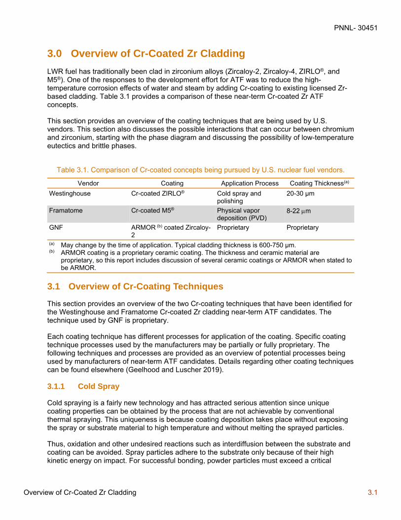
LWR fuel has traditionally been clad in zirconium alloys (Zircaloy-2, Zircaloy-4, ZIRLO®, and M5®). One of the responses to the development effort for ATF was to reduce the high-temperature corrosion effects of water and steam by adding Cr-coating to existing licensed Zr-based cladding. Table 3.1 provides a comparison of these near-term Cr-coated Zr ATF concepts.
This section provides an overview of the coating techniques that are being used by U.S. vendors. This section also discusses the possible interactions that can occur between chromium and zirconium, starting with the phase diagram and discussing the possibility of low-temperature eutectics and brittle phases.
Table 3.1. Comparison of Cr-coated concepts being pursued by U.S. nuclear fuel vendors.
Vendor Coating Application Process Coating Thickness(a)
Westinghouse Cr-coated ZIRLO® Cold spray and polishing
20-30 µm
Framatome Cr-coated M5® Physical vapor deposition (PVD)
8-22 m
GNF ARMOR (b) coated Zircaloy-2
Proprietary Proprietary
(a) May change by the time of application. Typical cladding thickness is 600-750 µm. (b) ARMOR coating is a proprietary ceramic coating. The thickness and ceramic material are
proprietary, so this report includes discussion of several ceramic coatings or ARMOR when stated to be ARMOR.
3.1 Overview of Cr-Coating Techniques
This section provides an overview of the two Cr-coating techniques that have been identified for the Westinghouse and Framatome Cr-coated Zr cladding near-term ATF candidates. The technique used by GNF is proprietary.
Each coating technique has different processes for application of the coating. Specific coating technique processes used by the manufacturers may be partially or fully proprietary. The following techniques and processes are provided as an overview of potential processes being used by manufacturers of near-term ATF candidates. Details regarding other coating techniques can be found elsewhere (Geelhood and Luscher 2019).
3.1.1 Cold Spray
Cold spraying is a fairly new technology and has attracted serious attention since unique coating properties can be obtained by the process that are not achievable by conventional thermal spraying. This uniqueness is because coating deposition takes place without exposing the spray or substrate material to high temperature and without melting the sprayed particles.
Thus, oxidation and other undesired reactions such as interdiffusion between the substrate and coating can be avoided. Spray particles adhere to the substrate only because of their high kinetic energy on impact. For successful bonding, powder particles must exceed a critical
PNNL- 30451
Overview of Cr-Coated Zr Cladding 3.2
velocity on impact, which is dependent on the properties of the spray material. This requires new concepts for the description of coating formation but also indicates applications beyond the market for typical thermal spray coatings (Gärtner et al. 2006; Maier et al. 2018, 2019; Yeom et al. 2019).
3.1.1.1 Conventional High-Pressure Cold Spray
This process is “a kinetic spray process utilizing supersonic jets of a compressed gas to accelerate, at or near-room temperature, powder particles to ultra-high velocities (up to 1,500 m/s). The unmolten particles traveling at speed between 500 and 1,500 m/s plastically deform and consolidate on impact with their substrate to create a coating” (Fauchais, Heberlein and Boulos 2014).
The basis of the cold spray process is the gas-dynamic acceleration of particles to supersonic velocities and hence high kinetic energies. This is achieved using Laval (convergent-divergent) nozzles. The upstream pressure is between 2 and 2.5 MPa for typical nozzle through diameters in the range of 2-3 mm. Gases used are N2, He, or their mixtures at very high flow rates (up to 5 m3/min). For stable conditions, typically the mass flow rate of the gas must be 10 times that of the entrained powder. For a powder flow rate of 6 kg/h, this means a volumetric flow rate of 336 m3/h for helium and 52.3 m3/h for nitrogen. Gases introduced (nitrogen or helium) are preheated up to 700-800°C to avoid their liquefaction under expansion and increase their velocity. With the highest gas flow rate, this means that the heating device must be capable of heating 90 m3/min to temperature up to 700-800°C. As particles are injected upstream of the nozzle throat, the powder feeder must be at slightly higher pressure compared to the upstream chamber pressure. Especially when spraying with He, the spray is performed within an enclosure to recycle gas (Fauchais et al. 2014).
Particles adhere to the substrate only if their impact velocity is above a critical value. Depending on the sprayed material, this may vary between about 500 and 900 m/s. The spray pattern covers an area of roughly 20-60 mm2, and spray rates are about 3-6 kg/h. Feed stock particle sizes are typically between 1 and 50 µm and deposition efficiencies reach easily 70-90%. Only ductile metals or alloys are sprayed owing to the impact-fusion coating buildup. Blends of ductile materials (>50 vol%) with brittle metals or ceramics are also used. It is important to emphasize that the substrate is not really heated by the gas exiting the gun (up to 200°C at the maximum). Current and expected application for cold spray coatings are electronic and electrical coatings, and coatings for the aircraft and automotive industries for localized corrosion protection (Fauchais et al. 2014).
3.1.1.2 Low-Pressure Cold Spray
The cost of high-pressure spray processes is rather high, especially because of the quantity of gases consumed (especially if it is helium), and the process is not adapted at all to spraying for onsite repair of parts. Portable equipment using air has been developed where the upstream pressure is below 1 MPa, typically 0.5 MPa, with a much lower gas consumption of about 0.4 m3/min (Fauchais et al. 2014).
Less power is required to preheat air, which is less expensive than N2 or He. The powder feeder can be simplified because pressurization is not necessary, and the powder can be injected downstream of the nozzle throat. With gas velocities in the 300-400 m/s range, the critical velocity of particles is not attained. To achieve coatings, small metal particles are mixed with bigger ones, which can be ceramics. Big particles mostly rebound upon impact, their role being

PNNL- 30451
Overview of Cr-Coated Zr Cladding 3.3
to “press” the small metal particles onto the substrate and the previously deposited layers (shot peening effect). Powder recuperation is hardly possible for multicomponent powder mixtures. The deposition efficiency is also much lower than with high-pressure guns, but the process is attractive for short production runs (Fauchais et al. 2014).
3.1.2 Physical Vapor Deposition
Physical vapor deposition (PVD) is a broad term used to describe the deposition of atoms, molecules, or the combination of atoms and molecules via condensation. In general, the term PVD encompasses evaporation, sputtering, and ion plating processes. These three processes are described in the following subsections (Pierson 1999; Grainger 1998).
3.1.2.1 Evaporation
Evaporative coatings are applied by heating the coating material (i.e., source) above the boiling point under low pressure (<10-3 Pa). This sends atoms or molecules through a cosine distribution of trajectories in a straight line to the substrate where they condense and form a thin film. At these low pressures, the mean-free path is large relative to the distance between the source and substrate and few collisions occur before the species condense on the substrate. This may lead to uneven coating thickness because the thickest part will be closest to the source. Uneven coatings may be avoided by employing planetary substrate holders and multiple sources. Evaporative coatings offer relatively high deposition rates (up to 75 µm/min) but complex shapes are difficult to accommodate, and the coatings often exhibit poor adhesion. A variety of different techniques are available for depositing evaporative coatings, such as reactive evaporation, plasma assisted or activated reactive evaporation, and molecular beam epitaxy. These techniques are described briefly in this section (Pierson 1999).
Reactive evaporation can be used to deposit refractory carbides, nitrides, and oxides, which have extremely high boiling points and tend to dissociate during evaporation. During reactive evaporation, the nonmetallic element of the coating (e.g., carbon, nitrogen, or oxygen) is introduced into the gas phase and a pure metal source is used (e.g., nitrogen used with a titanium source can produce titanium nitride) (Pierson 1999).
Plasma assisted or reactive evaporation can be used to enhance depositions rates using a plasma. A plasma is an ionized gas that is formed in the presence of an electromagnetic field under vacuum. The presence of the plasma enhances reactions in the gas phases and the growth kinetics of the deposit (Pierson 1999).
Molecular beam epitaxy (MBE) is another form of evaporative coating and can be used to produce extremely pure and very thin films with abrupt composition changes. The deposition rate for MBE is very slow and the process is still considered experimental. Nevertheless, MBE is considered for extremely exacting electronic and optoelectronic applications (Pierson 1999).
3.1.2.2 Sputtering
Sputtering is a technique used to create thin films. It is extensively used in the hard coating industry. High-quality coatings of refractory compounds and metals can be readily produced with good adhesion and composition control. In addition, since sputtering is not a thermally activated process, it is not associated with high temperature requirements like other coating processes (Pierson 1999).

PNNL- 30451
Overview of Cr-Coated Zr Cladding 3.4
During the sputtering process, a source (or target) is placed in a high vacuum and bombarded with gas ions (typically argon) that have been accelerated by high voltage, producing a glow discharge or plasma. Atoms from the target are physically ejected by the momentum transfer and travel across the vacuum chamber and are deposited on a substrate surface. Since the process is performed under low pressure, the mean-free path of the target atoms is relatively long, thus permitting the ejected atoms to condense on the intended surface (Pierson 1999).
Sputtering requires low pressure to remove all traces of background and contaminant gases, which could degrade the coating. This is typically achieved by cryogenic pumps capable of producing a vacuum of about 10-5 Pa with good pumping speed. After evacuation, the system is refilled with argon to a partial pressure of 0.1 to 10 Pa. Higher pressure, by placing too many argon atoms in the path of the ions and ejected atoms, would not allow these atoms or molecules to travel unimpeded by collision, effectively reducing the mean-free path and reducing the deposition rate. Sputtering can also be performed in the presence of a small partial pressure of hydrocarbons, nitrogen, or oxygen to react with ejected atoms and form carbide, nitride, or oxide coatings in a process called reactive sputtering. It is important to note, however, that reaction between the target material and the reactive species can poison the target and interfere with deposition (Pierson 1999).
The general disadvantages of sputtering include a relatively low deposition rate and a line-of-sight deposition characteristic that make the coating of deep holes and trenches difficult. This can be overcome to some extent by operating at higher pressure (but at some sacrifice in deposition rate) or by using three-dimensional grids. However, an advantage of sputtering is that the high energy of sputtered particles improves adhesion and produces a denser and more homogenous coating than evaporation (Pierson 1999).
The following is a list of commonly used sputtering techniques and a description of their attributes (Pierson 1999):
Diode sputtering – Simplest sputtering technique but requires an electrically conductive target, has low energy efficiency, and electron bombardment may cause significant damage of the substrate.
Radio-frequency sputtering – Frequencies above 50 kHz can sputter insulators, but the process has low deposition rates.
Triode sputtering – An additional cathode is used to sustain the plasma, but this configuration is more complicated and may contaminate the deposit.
Magnetron sputtering – Magnetically enhanced cathodes (magnetrons) have considerably expanded the potential of sputtering. The magnetron sends the electrons into spiral paths to increase collision frequency and ionization. Deposition rates are high, and the process does not cause electron radiation damage.
3.1.2.3 Ion Plating
In ion-plating deposition, the substrate and deposited film (as it forms) are subjected to bombardment by particles (ions, atoms, molecules) that alter the formation process and properties of the coating. The process is also called ion-beam assisted deposition (Pierson 1999).
Two basic versions of the ion beam plating process exist: plasma-based ion plating and vacuum-based ion plating. The coating material is vaporized in a manner similar to evaporation.
PNNL- 30451
Overview of Cr-Coated Zr Cladding 3.5
Typically, the plasma is obtained by biasing the substrate to a high negative potential (5 kV) at low pressure. The constant ion bombardment of the substrate sputters off some of the surface atoms, which results in improved adhesion and reduced impurities relative to other ion plating techniques. Surface coverage of discontinuities is also improved (Pierson 1999).
Reactive ion plating is similar to reactive sputtering and evaporation with applications in optical, wear, abrasion, lubrication, and decorative coating (Pierson 1999).
Another variant of ion plating is vacuum arc, cathodic arc, and multi-arc plating. This technique uses an electric arc to generate a plasma of target atoms. It is typically used for hard coatings like CrN and TiN. It typically forms dense, adherent films, but can result in macro-particle formation.
3.2 The Cr-Zr Phase Diagram
The substrate-coating interface must provide a sufficiently strong and stable bond throughout service to prevent delamination and benefit from the addition of the engineered coating. While some coating processes may result in a sufficiently adherent mechanical bond, many processes are conducted at elevated temperatures that result in a chemical bond at the substrate-coating interface. While chemical bonds are generally stronger and more robust than mechanical bonds, the characteristics of chemical bonds are ultimately dependent on the solid-state reactions at the interface. Cold spray and PVD are both examples of mechanical bonded coatings. Surface preparation is one of the most important aspects of any coating process. This is particularly critical for mechanically bonded coatings.
Interfacial solid-state reactions between the substrate and coating material occur in a manner similar to a diffusion couple. The resulting crystalline phase assemblage at the substrate-coating interface will influence the overall performance of the coated component and, as a result, the strength and stability of these interfacial phases is a critical aspect of an engineered coating.
Equilibrium phase diagrams of substrates and coating materials provide a convenient means of illustrating the range of crystalline phase assemblages that may be present at the interface. In addition to identifying interfacial phases, the phase diagram also provides transformation temperatures (e.g., melting, eutectic, various crystallographic morphologies, liquid phase) that may place additional limitations on the service environment of the coated component.
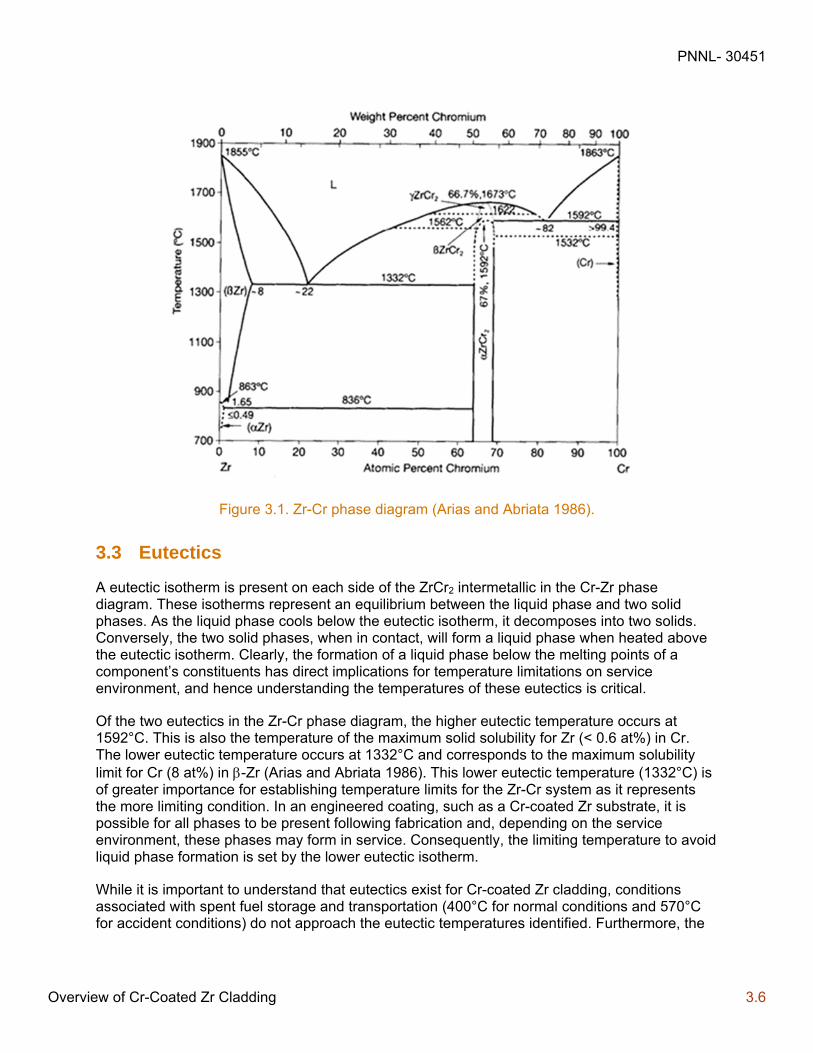
For chromium-coated zirconium substrates, the Zr-Cr phase diagram illustrates the equilibrium phases that may exist at the substrate-coating interface (see Figure 4.1; Arias and Abriata 1986). For ceramic coatings, such a CrN or Cr2O3, it would be necessary to examine a ternary phase diagram to determine the equilibrium phases that could be present. There is currently limited information regarding ternary phase diagrams of Cr-Zr-N or Cr-Zr-O, and none were located during this review.
PNNL- 30451
Overview of Cr-Coated Zr Cladding 3.6
Figure 3.1. Zr-Cr phase diagram (Arias and Abriata 1986).
3.3 Eutectics
A eutectic isotherm is present on each side of the ZrCr2 intermetallic in the Cr-Zr phase diagram. These isotherms represent an equilibrium between the liquid phase and two solid phases. As the liquid phase cools below the eutectic isotherm, it decomposes into two solids. Conversely, the two solid phases, when in contact, will form a liquid phase when heated above the eutectic isotherm. Clearly, the formation of a liquid phase below the melting points of a component’s constituents has direct implications for temperature limitations on service environment, and hence understanding the temperatures of these eutectics is critical.
Of the two eutectics in the Zr-Cr phase diagram, the higher eutectic temperature occurs at 1592°C. This is also the temperature of the maximum solid solubility for Zr (< 0.6 at%) in Cr. The lower eutectic temperature occurs at 1332°C and corresponds to the maximum solubility limit for Cr (8 at%) in -Zr (Arias and Abriata 1986). This lower eutectic temperature (1332°C) is of greater importance for establishing temperature limits for the Zr-Cr system as it represents the more limiting condition. In an engineered coating, such as a Cr-coated Zr substrate, it is possible for all phases to be present following fabrication and, depending on the service environment, these phases may form in service. Consequently, the limiting temperature to avoid liquid phase formation is set by the lower eutectic isotherm.
While it is important to understand that eutectics exist for Cr-coated Zr cladding, conditions associated with spent fuel storage and transportation (400°C for normal conditions and 570°C for accident conditions) do not approach the eutectic temperatures identified. Furthermore, the
PNNL- 30451
Overview of Cr-Coated Zr Cladding 3.7
inner surface of the cladding is not coated, so there is no additional concern regarding the fuel and cladding interaction.
3.4 Brittle Phases
An intermetallic compound, ZrCr2, is present in the Zr-Cr phase diagram. Intermetallic compounds generally have high melting points and low densities and exhibit superior corrosion and oxidation resistance that make them candidates for high-temperature structural materials. The ZrCr2 intermetallic is a topologically close-packed Laves phase of the form AB2. Intermetallic compounds such as these are typically brittle at low temperature due to their complex crystal structure.
The intermetallic compound, ZrCr2, is present in three stable phases on the Zr-Cr phase diagram. These include , , and -ZrCr2, which are the low, intermediate, and high-temperature phases of the compound. The -phase has a composition range of 64-69 at% Cr at 900°C and transforms to the -phase at about 1592°C. The high temperature -phases is only stable between 1622°C ( to transformation) and its congruent melting temperature (1673°C). Note that severe experimental difficulties are found in the ZrCr2 compositional range due to the long times and high temperature required to attain stable equilibrium. Consequently, the details of the + phase region of the Cr-Zr phase diagram is incomplete and rather speculative (Arias and Abriata 1986). This would only be a concern above 1592°C
The intermetallic compound, ZrCr2, can form due to diffusion of atoms in the Zr substrate and Cr atoms in the coating. The formation of this intermetallic has been observed with a thickness of 4 m after 66 hours at 775°C (Sweeney and Batt 1964). The formation of this intermetallic has also been observed with a thickness between 1 and 4.5 m after 49 to 225 hours at 750°C to 850°C (Wenxin and Shihao 2001). As with the eutectics previously discussed, the conditions associated with spent fuel storage and transportation (400°C for normal conditions and 570°C for accident conditions) do not approach the temperatures where significant interdiffusion would occur beyond what may have occurred in-reactor.
3.5 Cr-Coated Zr Cladding Degradation and Failure Modes
Unlike in-reactor safety analysis, there are no specific safety limits put on the fuel cladding for spent fuel storage and transportation analysis. However, to certify that DSS or transportation package is safe, a number of safety analyses are performed and an accurate knowledge of the thermal and mechanical state of the fuel cladding is necessary. Therefore, it is critical to understand how these properties have changed relative to the fresh fuel condition following irradiation.
It is known that irradiation of Zr-alloy cladding will cause degradation to the cladding such that there is a possibility of failure either in-reactor or out of reactor during storage and transportation.
In-reactor, the following changes to Cr-coated Zr tubes are possible relative to the unirradiated conditions:
Increase in yield stress
Decrease in ductility
PNNL- 30451
Overview of Cr-Coated Zr Cladding 3.8
Decrease in fatigue life
Coating cracking or delamination
Cr-Zr interdiffusion
Radiation effects on Cr
Galvanic corrosion
Additionally, a number of aging-related damage mechanisms that could impact the cladding during long-term storage have been identified for Zr-alloy tubes and are likely applicable to Cr-coated Zr cladding as well. These include:
Embrittlement (typically caused by hydride reorientation in Zr-alloy tubes)
Delayed hydride cracking
Thermal and athermal creep
The regulations and guidance for spent fuel analysis are discussed in greater detail in Section 5.0, including a discussion of information that would be required to adequately model Cr-coated Zr cladding.
PNNL- 30451
Overview of GNF FeCrAl Alloys 4.1
4.0 Overview of GNF FeCrAl Alloys
FeCrAl alloys have historically been used in industrial applications where high-temperature oxidation resistance is needed. Development of FeCrAl alloys has been performed by commercial entities, national laboratories, and universities, with collaboration between the different research sectors. Both wrought FeCrAl and powder metallurgy based FeCrAl alloys are under development. Within the nuclear industry, focus has been on the wrought alloys, considered to be “nuclear grade,” which in this context means an optimized composition to perform within the full range of reactor operating conditions.
FeCrAl alloys consist of iron (Fe), chromium (Cr), and aluminum (Al), with minor alloying additions for various purposes. There are commercially available variants; however, the main focus of U.S. R&D programs is to develop a wrought oxidation-resistant alloy variant; the Japanese effort intends to greatly improve on the strength by pursuing ODS FeCrAl alloys (Terrani 2018).
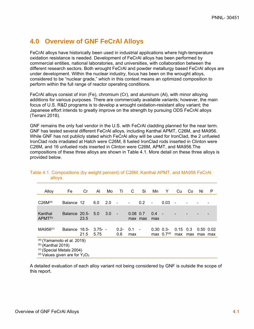
GNF remains the only fuel vendor in the U.S. with FeCrAl cladding planned for the near term. GNF has tested several different FeCrAl alloys, including Kanthal APMT, C26M, and MA956. While GNF has not publicly stated which FeCrAl alloy will be used for IronClad, the 2 unfueled IronClad rods irradiated at Hatch were C26M, 8 fueled IronClad rods inserted in Clinton were C26M, and 16 unfueled rods inserted in Clinton were C26M, APMT, and MA956.The compositions of these three alloys are shown in Table 4.1. More detail on these three alloys is provided below.
Table 4.1. Compositions (by weight percent) of C26M, Kanthal APMT, and MA956 FeCrAl alloys.
Alloy Fe Cr Al Mo Ti C Si Mn Y Cu Co Ni P
C26M(a) Balance 12 6.0 2.0 - - 0.2 - 0.03 - - - -
Kanthal APMT(b)
Balance 20.5-23.5
5.0 3.0 - 0.08 max
0.7 max
0.4 max
- - - - -
MA956(c) Balance 18.5-21.5
3.75-5.75
- 0.2-0.6
0.1 max
- 0.30 max
0.3-0.7(d)
0.15 max
0.3 max
0.50 max
0.02 max
(a) (Yamamoto et al. 2019) (b) (Kanthal 2019) (c) (Special Metals 2004) (d) Values given are for Y2O3
A detailed evaluation of each alloy variant not being considered by GNF is outside the scope of this report.
PNNL- 30451
Overview of GNF FeCrAl Alloys 4.2
4.1 FeCrAl Design
FeCrAl alloys are fully ferritic (body-centric-cubic structure) with typically no phase transformation to or from austenite (face-centered-cubic structure) between liquidus temperature and room temperature due to the Cr and Al additive effects on Fe-based alloys (Field et al. 2018). Cr additions contribute to corrosion resistance by forming a layer of chromium oxide (or chromia) under normal conditions; Al additions improve high-temperature oxidation resistance by forming an aluminum oxide (or alumina) layer under accident conditions (Rebak 2018a). The Cr additions further stabilize the alumina layer in high-temperature steam.
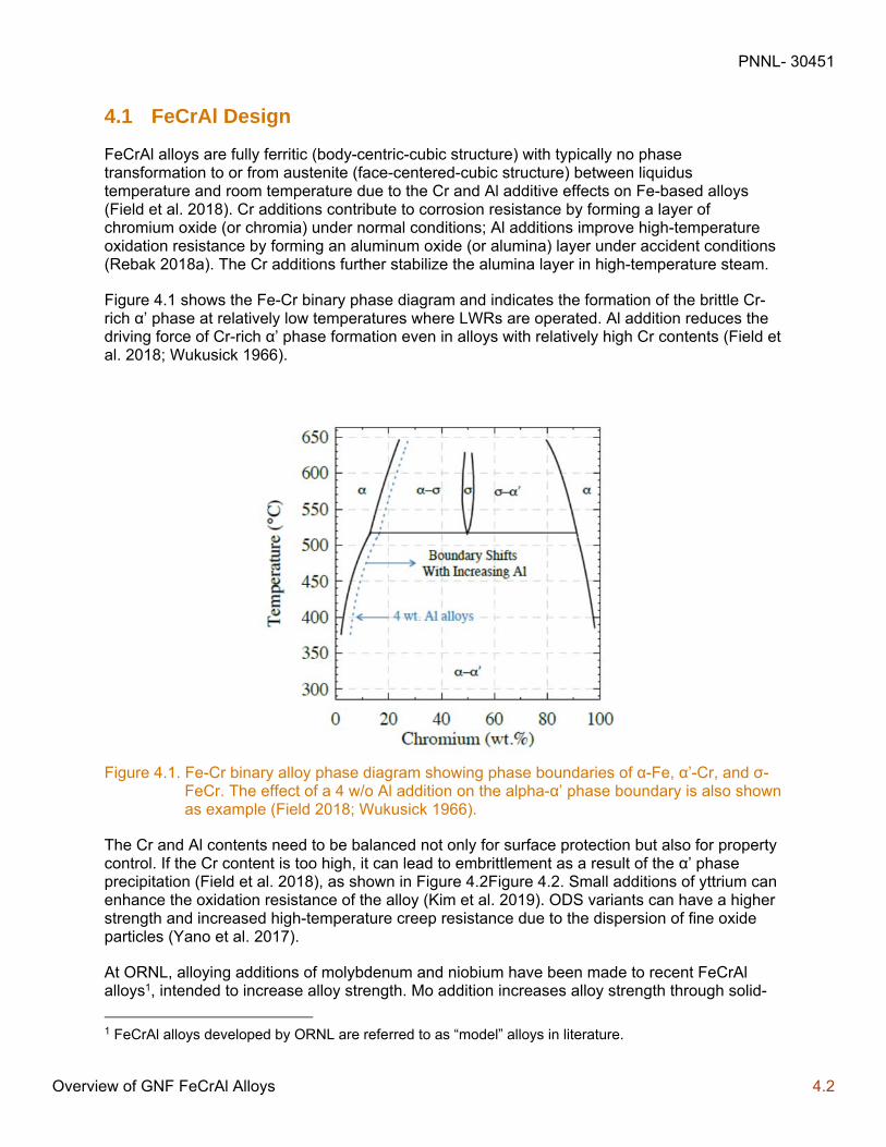
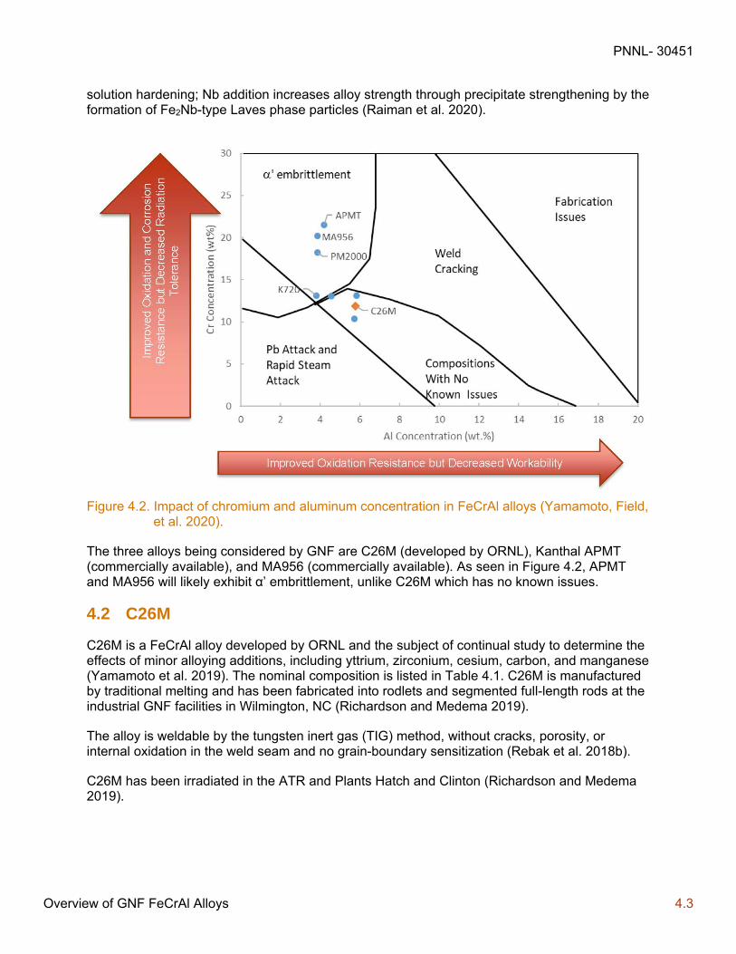
Figure 4.1 shows the Fe-Cr binary phase diagram and indicates the formation of the brittle Cr-rich α’ phase at relatively low temperatures where LWRs are operated. Al addition reduces the driving force of Cr-rich α’ phase formation even in alloys with relatively high Cr contents (Field et al. 2018; Wukusick 1966).
Figure 4.1. Fe-Cr binary alloy phase diagram showing phase boundaries of α-Fe, α’-Cr, and σ-FeCr. The effect of a 4 w/o Al addition on the alpha-α’ phase boundary is also shown as example (Field 2018; Wukusick 1966).
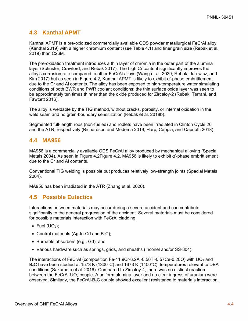
The Cr and Al contents need to be balanced not only for surface protection but also for property control. If the Cr content is too high, it can lead to embrittlement as a result of the α’ phase precipitation (Field et al. 2018), as shown in Figure 4.2Figure 4.2. Small additions of yttrium can enhance the oxidation resistance of the alloy (Kim et al. 2019). ODS variants can have a higher strength and increased high-temperature creep resistance due to the dispersion of fine oxide particles (Yano et al. 2017).
At ORNL, alloying additions of molybdenum and niobium have been made to recent FeCrAl alloys1, intended to increase alloy strength. Mo addition increases alloy strength through solid-
1 FeCrAl alloys developed by ORNL are referred to as “model” alloys in literature.
PNNL- 30451
Overview of GNF FeCrAl Alloys 4.3
solution hardening; Nb addition increases alloy strength through precipitate strengthening by the formation of Fe2Nb-type Laves phase particles (Raiman et al. 2020).
Figure 4.2. Impact of chromium and aluminum concentration in FeCrAl alloys (Yamamoto, Field, et al. 2020).
The three alloys being considered by GNF are C26M (developed by ORNL), Kanthal APMT (commercially available), and MA956 (commercially available). As seen in Figure 4.2, APMT and MA956 will likely exhibit α’ embrittlement, unlike C26M which has no known issues.
4.2 C26M
C26M is a FeCrAl alloy developed by ORNL and the subject of continual study to determine the effects of minor alloying additions, including yttrium, zirconium, cesium, carbon, and manganese (Yamamoto et al. 2019). The nominal composition is listed in Table 4.1. C26M is manufactured by traditional melting and has been fabricated into rodlets and segmented full-length rods at the industrial GNF facilities in Wilmington, NC (Richardson and Medema 2019).
The alloy is weldable by the tungsten inert gas (TIG) method, without cracks, porosity, or internal oxidation in the weld seam and no grain-boundary sensitization (Rebak et al. 2018b).
C26M has been irradiated in the ATR and Plants Hatch and Clinton (Richardson and Medema 2019).
PNNL- 30451
Overview of GNF FeCrAl Alloys 4.4
4.3 Kanthal APMT
Kanthal APMT is a pre-oxidized commercially available ODS powder metallurgical FeCrAl alloy (Kanthal 2019) with a higher chromium content (see Table 4.1) and finer grain size (Rebak et al. 2019) than C26M.
The pre-oxidation treatment introduces a thin layer of chromia in the outer part of the alumina layer (Schuster, Crawford, and Rebak 2017). The high Cr content significantly improves the alloy’s corrosion rate compared to other FeCrAl alloys (Wang et al. 2020; Rebak, Jurewicz, and Kim 2017) but as seen in Figure 4.2, Kanthal APMT is likely to exhibit α’-phase embrittlement due to the Cr and Al contents. The alloy has been exposed to high-temperature water simulating conditions of both BWR and PWR coolant conditions; the thin surface oxide layer was seen to be approximately ten times thinner than the oxide produced for Zircaloy-2 (Rebak, Terrani, and Fawcett 2016).
The alloy is weldable by the TIG method, without cracks, porosity, or internal oxidation in the weld seam and no grain-boundary sensitization (Rebak et al. 2018b).
Segmented full-length rods (non-fueled) and rodlets have been irradiated in Clinton Cycle 20 and the ATR, respectively (Richardson and Medema 2019; Harp, Cappia, and Capriotti 2018).
4.4 MA956
MA956 is a commercially available ODS FeCrAl alloy produced by mechanical alloying (Special Metals 2004). As seen in Figure 4.2Figure 4.2, MA956 is likely to exhibit α’-phase embrittlement due to the Cr and Al contents.
Conventional TIG welding is possible but produces relatively low-strength joints (Special Metals 2004).
MA956 has been irradiated in the ATR (Zhang et al. 2020).
4.5 Possible Eutectics
Interactions between materials may occur during a severe accident and can contribute significantly to the general progression of the accident. Several materials must be considered for possible materials interaction with FeCrAl cladding:
Fuel (UO2);
Control materials (Ag-In-Cd and B4C);
Burnable absorbers (e.g., Gd); and
Various hardware such as springs, grids, and sheaths (Inconel and/or SS-304).
The interactions of FeCrAl (composition Fe-11.9Cr-6.2Al-0.50Ti-0.57Ce-0.20O) with UO2 and B4C have been studied at 1573 K (1300°C) and 1673 K (1400°C), temperatures relevant to DBA conditions (Sakamoto et al. 2016). Compared to Zircaloy-4, there was no distinct reaction between the FeCrAl-UO2 couple. A uniform alumina layer and no clear ingress of uranium were observed. Similarly, the FeCrAl-B4C couple showed excellent resistance to materials interaction.
PNNL- 30451
Overview of GNF FeCrAl Alloys 4.5
The interactions of FeCrAl (Alloy B136Y, with composition Fe-13Cr-6.2Al-0.03Y) with SS-304, Inconel, and B4C have been studied at temperatures ranging from 1300 °C to 1500 °C (Robb, Howell, and Ott 2018). These tests did not show signs of interaction for test temperatures up to 1400 °C for the FeCrAl/SS-304 combination and up to 1450 °C for the FeCrAl/Inconel and FeCrAl/B4C combinations.
The FeCrAl/B4C test conducted at 1500 °C appeared to have some melting of the FeCrAl; however, part of the testing apparatus fell during the experiment so the test will be repeated in the future. Fe/B4C is known to form a low melting eutectic at approximately 1150 °C. It is postulated that a thin oxide layer protects the FeCrAl from the B4C, which can be confirmed by future by cross-sectional micrographs.
During the QUENCH-19 test performed at Karlsruhe Institute of Technology, FeCrAl (Alloy B136Y, with composition Fe-13Cr-6.2Al-0.03Y) cladding was damaged due to probable melting or by interaction with molten SS-304 thermocouples, which have a melting temperature in the range of 1400 to 1450 °C (Stuckert et al. 2019). This could indicate eutectic interaction between FeCrAl and SS-304; however, it is possible that the cladding reached the melting point of FeCrAl as there were uncertainties in the temperature measurements and several thermocouples fail.
While it is important to understand that eutectics exist for FeCrAl cladding, conditions associated with spent fuel storage and transportation (400°C for normal conditions and 570°C for accident conditions) do not approach the eutectic temperatures identified. Furthermore, the inner surface of the cladding is not coated, so there is no additional concern regarding the fuel and cladding interaction.
4.6 FeCrAl Cladding Degradation and Failure Modes
Unlike in-reactor safety analysis, there are no specific safety limits put on the fuel cladding for spent fuel storage and transportation analysis. However, to certify that a DSS or transportation package is safe, several safety analyses are performed and an accurate knowledge of the thermal and mechanical state of the fuel cladding is necessary. Therefore, it is critical to understand how these properties have changed relative to the fresh fuel condition following irradiation.
It is known that irradiation of Zr-alloy cladding will cause degradation to the cladding such that there is a possibility of failure either in-reactor or out of reactor due during storage and transportation. It is likely that similar degradation will occur in FeCrAl cladding.
In-reactor, the following changes to FeCrAl tubes are possible relative to the unirradiated conditions:
Increase in yield stress
Decrease in ductility
Decrease in fatigue life
Radiation Effects on FeCrAl
Galvanic corrosion

PNNL- 30451
Overview of GNF FeCrAl Alloys 4.6
Additionally, a number of aging-related damage mechanisms that could impact the cladding during long term storage have been identified for Zr-alloy tubes and may be applicable to FeCrAl cladding as well. These include:
Embrittlement
Delayed hydride cracking
Thermal and athermal creep
The regulations and guidance for spent fuel analysis are discussed in greater detail in Section 5.0, including a discussion of information that would be required to adequately model FeCrAl cladding.
PNNL- 30451
Storage and Transportation of Spent Nuclear Fuel 5.1
5.0 Storage and Transportation of Spent Nuclear Fuel
The safety analyses for storage and transportation of spent nuclear fuel (SNF) is somewhat different than the in-reactor performance. The storage and transportation of SNF has not been historically considered as a part of the fuel design process. There are currently no in-reactor operating restrictions that are in place because of SNF considerations. However, the peak cladding temperature and average-rod hoop stresses during drying operations are limited via guidance. These limits may need to be revised depending on advances in ATF fuel cladding performance. Additionally, the individual rod power histories are not available for the analysis of SNF during drying, loading, storage, or transportation. Therefore, the safety limits for storage and transportation of SNF must be developed for the most limiting fuel rods at the maximum expected burnup.
For spent fuel storage and transportation, burnup has a profound impact on the safety analysis. Currently licensed cladding is affected in the following ways: As burnup progresses, cladding strength goes up, and ductility down; cladding is thinned by the corrosion process; increased cladding hydrogen concentration causes embrittlement; and increased fission gas release leads to increased rod internal pressure and increased radioactive source term for accident analyses.
It is worth noting that an additional motivation for development of ATF fuels is the side benefit of improving fuel performance in high burnup conditions. Accordingly, burnup-dependent guidance for storage and transportation applications may need to be revised yet again once an assessment of ATF fuel concepts can be made for high burnup operation.
PNNL performed a critical review of the regulations and guidance regarding the storage and transportation of SNF. The general conclusions of this review are that the relevant regulations (10 CFR 72) do not specifically prohibit the use of either of the near-term ATF cladding concepts as the requirements are fairly general. NRC standard review plans (SRP) for dry storage systems (NUREG-1567 and NUREG-1536, replaced by NUREG-2215) and transportation of SNF (NUREG-1617, replaced by NUREG-2216) (US Nuclear Regulatory Commission 2020a; US Nuclear Regulatory Commission 2020b) mention Zr-alloy cladding and stainless steel. There is no mention of either near-term ATF concept in these documents; however, due to the similarity of Cr-coated cladding with Zr-alloy cladding, and FeCrAl cladding with stainless steel cladding, it is possible to assess the data needs and applicability of these alloys to the requirements and recommendations in these documents. The one area that deserves additional scrutiny from these documents is the empirically derived temperature and stress limits in the SRP.
The integrity of zirconium-based alloy cladding and all fuel burnups (low and high): The maximum calculated fuel-cladding temperature should not exceed 400°C (752 °F) for normal conditions of storage and short-term loading operations, including DSS drying and backfilling.
A higher temperature limit may only be used for low burnup SNF (less than 45 gigawatt days MTU), as long as the applicant can demonstrate that the best estimate cladding hoop stress is equal to or less than 90 MPa (13.1 ksi) for the proposed temperature limit.
During loading operations, repeated thermal cycling should be limited to less than 10 cycles when the cladding temperature difference exceeds 65°C (149°F).
PNNL- 30451
Storage and Transportation of Spent Nuclear Fuel 5.2
For off-normal and accident conditions the maximum cladding temperature should not exceed 570°C (1,058°F).
For the integrity of stainless-steel cladding, the maximum calculated fuel cladding temperature should not exceed 570°C (1058°F) for off-normal and accident conditions and the maximum calculated fuel cladding temperature should not exceed 400°C (752°F) for normal conditions of storage and short-term loading operations, including storage container drying and backfilling.
Hydrogen content: Per NUREG-2214, for burnups above 45 GWd/MTU and up to 62 GWd/MTU, the hydrogen content is noted for Zircaloy-2, Zircaloy-4, ZIRLO®, and M5®. NUREG-2215 (US Nuclear Regulatory Commission 2020a) does not call out a specific hydrogen content
These temperature and stress limits are empirically derived for current fuel designs with current cladding materials. Each of these limits should be assessed to determine if they are applicable to any near-term ATF cladding concept. With the hydrogen content, it is noted that the Cr coating will likely reduce the oxide thickness and subsequent hydrogen content to very low values and should not be an issue for Cr-coated Zr cladding. Embrittlement can be caused by interdiffusion between Cr and Zr, but this is not expected to be significant (see Section 3.4). For FeCrAl, iron is not embrittled by hydrogen as zirconium is and thus hydrogen embrittlement is not an issue (Hales and Gamble 2015). NRC should be made aware of any other environmental factor that could embrittle either ATF cladding concept.
The following subsections provide a critical evaluation of the documents that provide the regulatory framework for the safety analyses regarding the, wet storage (Section 5.1), dry storage (Section 5.2), and transportation (Section 0) of SNF as it relates to near-term ATF concepts.
5.1 Wet Storage of Spent Nuclear Fuel
This section discusses the wet storage of SNF, including the current regulatory framework and its application to near-term ATF concepts.
5.1.1 Current Regulatory Framework
The regulations related to wet storage of SNF are provided in 10 CFR Part 50, “Domestic Licensing of Production and Utilization Facilities” (US Nuclear Regulatory Commission 2017) as General Design Criteria (GDC) 61, “Fuel Storage and Handling and Radioactivity Control.” Specifically, GDC 61 requires (1) periodic inspections; (2) suitable radiation shielding; (3) appropriate containment, confinement, and filtering systems; (4) residual heat removal capability consistent with its importance to safety; and (5) prevention of significant reduction in fuel storage inventory under accident conditions. To augment those requirements, the spent fuel pool design basis is also covered by GDC 2, “Design Bases for Protection Against Natural Phenomena”; GDC 4, “Environmental and Dynamic Effects Design Bases”; and GDC 63, “Monitoring Fuel and Waste Storage.” 1
To meet the requirements of GDC 61, 2, 4, and 63, it is important that the spent fuel storage pool structures, systems, and components be designed to accomplish the following:
1 10 CFR Part 72 can also apply to wet storage, if the wet storage facility is away from a reactor (e.g., GE-Morris spent fuel pool is licensed under Part 72 as a site specific ISFSI)

PNNL- 30451
Storage and Transportation of Spent Nuclear Fuel 5.3
Prevent loss of water from the fuel pool that would lead to water levels that are inadequate for cooling or shielding
Protect the fuel from mechanical damage
Provide the capability to limit potential offsite exposures in the event of a significant release of radioactivity from the fuel or significant leakage of pool coolant
Provide adequate cooling to the spent fuel to remove residual heat
5.1.2 Application to Cr-Coated Zr Cladding
For Cr-coated Zr cladding, it is unlikely that the irradiated cladding mechanical properties will be significantly different from the uncoated Zr-alloy irradiated properties. If this is confirmed with test data from irradiated Cr-coated Zr cladding, then it would be reasonable to use existing spent fuel pool analyses for Cr-coated Zr fuel rods.
Additionally, the heat load from Cr-coated Zr clad fuel rods is expected to be the same as that of uncoated Zr-alloy clad fuel rods, so there will likely be no impact on the residual heat analysis assuming current burnup limits remain the same.
5.1.3 Application to FeCrAl Cladding
The mechanical properties of FeCrAl cladding are not the same as Zr-alloy cladding. Additionally, initial FeCrAl cladding designs use thinner cladding than the Zr-alloy cladding they are replacing. An analysis to show that the fuel is protected from mechanical damage should be performed using representative cladding dimensions and mechanical properties taken from irradiated cladding tubes.
Additionally, although the heat load from FeCrAl clad fuel rods is expected to be the same as that of uncoated Zr-alloy clad fuel rods at current burnup limits, there is the possibility of Co-60 activation from Fe that could lead to increased worker dose and thus it should be considered in the spent fuel analysis.
5.2 Dry Storage of Spent Nuclear Fuel
This section discusses the dry storage of SNF, including the current regulatory framework and its application to near-term ATF concepts.
5.2.1 Current Regulatory Framework
The regulations in 10 CFR Part 72, “Licensing Requirements for the Independent Storage of Spent Nuclear Fuel, High-Level Radioactive Waste, and Reactor-Related Greater Than Class C Waste” (US Nuclear Regulatory Commission 2015), include a number of fuel-specific and dry storage system (DSS)-specific requirements that may be dependent of the design basis condition of the fuel cladding. 10 CFR 72.44(c) states that a specific license for dry storage of SNF is to include technical specifications that, among other things, define limits on the fuel and allowable geometric arrangements. Additionally, 10 CFR 72.236(a) states that, a Certificate of Compliance for a DSS design must include specifications for:
The type of spent fuel (i.e., BWR, PWR, or both)
Maximum allowable enrichment of the fuel prior to any irradiation
PNNL- 30451
Storage and Transportation of Spent Nuclear Fuel 5.4
Burnup
Minimum acceptable cooling time of the spent fuel before storage in the spent fuel DSS
Maximum heat designed to be dissipated
Maximum spent fuel loading limit
Condition of the spent fuel (i.e., intact assembly or consolidated fuel rods)
Inerting atmosphere requirements.
The condition of the SNF cladding is critical to the storage as 10 CFR 72.122(h)(1) states that the SNF cladding is to be protected against degradation that leads to gross ruptures or the fuel must be otherwise confined such that degradation of the fuel during storage will not pose operational safety problems with respect to its removal from storage. Additionally, CFR 72.122(l) states that the DSS must be designed to allow ready retrieval of the SNF.1
In addition to these regulations, the NRC staff have provided NUREG-1536, Rev. 1, “Standard Review Plan for Spent Fuel Dry Storage Systems at a General Licensing Facility” (US Nuclear Regulatory Commission 2010), and NUREG-1567, “Standard Review Plan for Spent Fuel Dry Storage Facilities” (US Nuclear Regulatory Commission 2000). These guidelines have recently been replaced by NUREG-2215 (US Nuclear Regulatory Commission 2020a). These standard review plans provide guidance to the staff on reviewing applications for DSS Certificates of Compliance or ISFSI site-specific licenses under 10 CFR Part 72. The SRP lays out the following evaluations that should be performed during the safety evaluation of a DSS shown in Figure 5.1.
1 “Ready retrieval” is defined as an ability to retrieve a fuel assembly intact using its normal lifting hardware
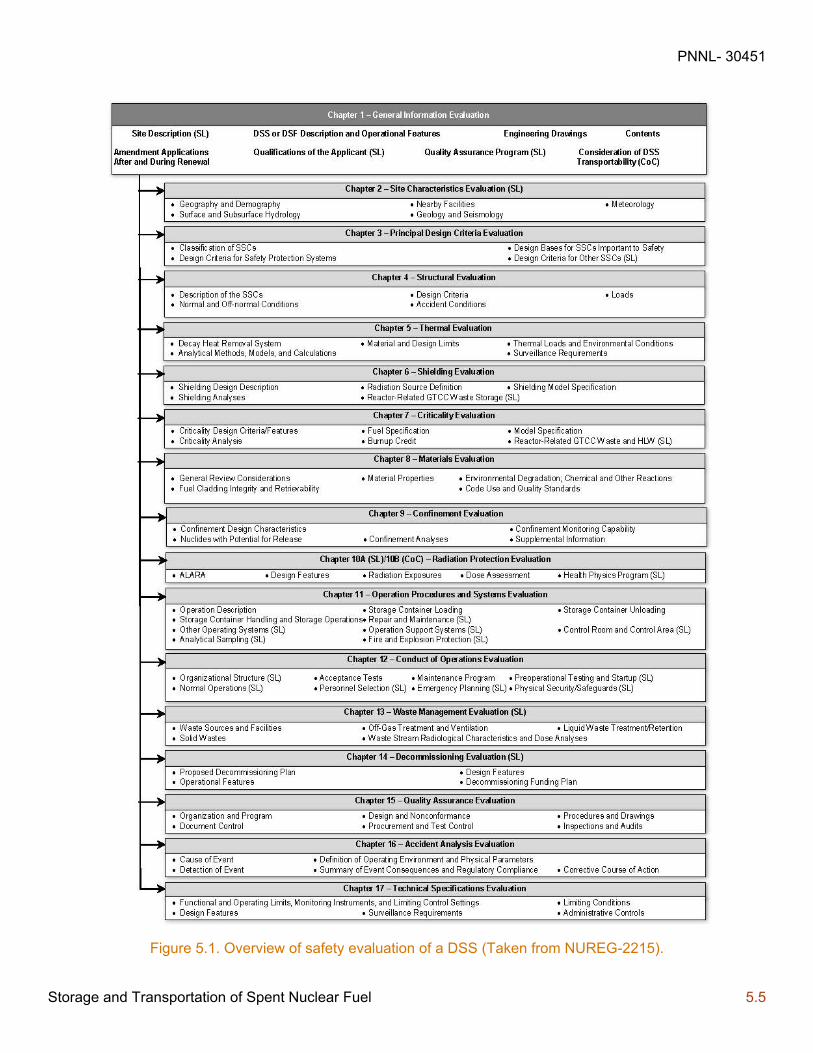
PNNL- 30451
Storage and Transportation of Spent Nuclear Fuel 5.5
Figure 5.1. Overview of safety evaluation of a DSS (Taken from NUREG-2215).
PNNL- 30451
Storage and Transportation of Spent Nuclear Fuel 5.6
As burnups have progressed and new data have become available, NRC staff published Interim Staff Guidance 11 (ISG-11) regarding cladding considerations for the transportation and storage of spent fuel. This information is used to supplement the guidance in the standard review plan. The standard review plan NUREG-1536, Rev. 1 (US Nuclear Regulatory Commission 2010) was revised in 2010 to reflect the latest guidance in ISG-11, Rev. 3. NUREG-1567 (US Nuclear Regulatory Commission 2000) was replaced by NUREG-2215 (US Nuclear Regulatory Commission 2020a) and incorporates ISG-11, Rev. 3.
ISG-11 has been periodically revised as more data have become available. The following summary lists the main guidance provided in each revision to ISG-11:
ISG-11, Rev.0
Supplement the standard review plan by addressing potential degradation of high burnup fuel (> 45 GWd/MTU).
ISG-11, Rev. 1
Incorporate new data
Give applicant responsibility for demonstrating that the cladding is adequately protected
Cladding oxidation should not be credited as load-bearing in the fuel cladding structural evaluation
Defined a 1% creep strain limit on the cladding
Only accounted for Zircaloy-clad fuel rods (no advanced cladding).
ISG-11, Rev. 2
Changed the definition of damaged fuel
Removed the 1-percent creep strain limit
Discuss criteria to limit hydride reorientation in the cladding
Applicable to all zirconium-alloy claddings and all burnup levels
Described calculations to determine the maximum cladding temperature per a justified creep strain limit.
ISG-11, Rev. 3
Replaced calculation of maximum cladding temperature per a justified creep strain limit with a generic 400°C peak cladding temperature limit for normal conditions of storage (NCS) and normal conditions of transport (NCT).
Allowed a higher short-term temperature limit for low-burnup fuel if it could be demonstrated that cladding hoop strain does not exceed 90 MPa.
Generic maximum cladding temperature limit of 570°C for off-normal and accident conditions applicable to all burnups.
Minimize hydride reorientation by restricting change in cladding temperature during drying operations to 65°C and the cladding should not experience more than 10 thermal cycles each not exceeding 65°C.
PNNL- 30451
Storage and Transportation of Spent Nuclear Fuel 5.7
NRC staff has recently provided a draft NUREG (NUREG-2224) that is out for comment regarding dry storage and transportation of high burnup SNF (Ahn, et al. 2018). This document seems to consider fuel with burnup up to 65 GWd/MTU. Additionally, NRC staff recently presented their thoughts on the management of high burnup spent fuel (Torres 2018). With regard to storage of SNF, these documents discussed the roles of cladding creep and hydride reorientation. These documents also provided guidance for dry storage for less than 20 years and for dry storage for greater than 20 years.
Regarding operability and safety significance of aging mechanisms of the fuel cladding/assembly hardware on the performance of the fuel for dry storage periods up to 60 years, NRC has issued NUREG-2214 (US Nuclear Regulatory Commission 2019) that provides the technical basis for these issues.
5.2.2 Application to Cr-Coated Zr Cladding
In examining the safety evaluations that should be performed on a DSS shown in Figure 5.1, the items that are expected to be impacted by use of Cr-coated Zr cladding are:
Structural Evaluation: Component Materials
Thermal Evaluation: Spent Fuel Cladding, Component Materials
Confinement Evaluation: Component Materials
Shielding Evaluation: Component Materials
Criticality Evaluation: Component Materials
Materials Evaluation: Cladding Integrity
Based on these needs, the following information is needed to support the safety analysis of a DSS containing Cr-coated clad fuel:
New cladding mechanical properties (yield stress, ultimate tensile strength, uniform elongation).
As previously discussed, the application of a thin Cr-coating to Zr-alloy cladding is unlikely to impact the mechanical properties or the nuclear properties of the irradiated cladding. Therefore, if data are provided to justify this, the current safety analysis of a DSS containing uncoated Zr-alloy clad fuel could be applied to Cr-coated Zr-alloy fuel.
Necessary updates to in-reactor codes and methods have been discussed elsewhere (Geelhood and Luscher 2019) and will be necessary to provide bounding conditions regarding the following conditions of spent fuel:
Rod internal pressure (likely not significantly impacted by Cr coating)
Oxide thickness (likely will be bounded by uncoated cladding)
Hydrogen content (likely will be bounded by uncoated cladding)
To address the issues of cladding creep and hydride reorientation (embrittlement), the applicant should also justify the following limits that are articulated in ISG-11, Rev. 3 and have historically been used for storage of SNF:
400°C peak cladding temperature limit for NCS
PNNL- 30451
Storage and Transportation of Spent Nuclear Fuel 5.8
Maximum cladding temperature limit of 570°C for off-normal and accident conditions
The cladding should not experience more than ten thermal cycles each not exceeding 65°C
Data that could be used to assess these needs are summarized in Section 5.4.
5.2.3 Application to FeCrAl Cladding
In examining the safety evaluations that should be performed on a DSS, shown in Figure 5.1, the items that are expected to be impacted by use of FeCrAl cladding are:
Principal Design Criteria Evaluation: Spent Fuel Design Basis
Structural Evaluation: Component Materials, Dimensions and Weights
Thermal Evaluation: Spent Fuel Cladding, Component Materials, Decay Heat, Dimensions
Confinement Evaluation: Component Materials, Dimensions
Shielding Evaluation: Component Materials, Dimensions
Criticality Evaluation: Component Materials, Dimensions
Materials Evaluation: Cladding Integrity
Based on these needs, the following information on FeCrAl cladding is needed to support the safety analysis of a DSS containing FeCrAl clad fuel:
New cladding mechanical properties (yield stress, ultimate tensile strength, uniform elongation)
New cladding thermal properties (thermal conductivity, specific heat, thermal expansion)
New cladding dimensions (FeCrAl cladding anticipated to be thinner than Zr-alloy cladding)
FeCrAl activation following irradiation
FeCrAl neutron cross sections
Necessary updates to in-reactor codes and methods have been discussed elsewhere (Goodson and Geelhood 2020) and will be necessary to provide bounding conditions regarding the following conditions of spent fuel:
Rod internal pressure
Oxide thickness (likely will be minimal)
To address the issues of cladding creep and embrittlement, the applicant should also justify the following limits that are articulated in ISG-11 Rev. 3 and have historically been used for storage of SNF:
400°C peak cladding temperature limit for NCS
Maximum cladding temperature limit of 570°C for off-normal and accident conditions
The cladding should not experience more than ten thermal cycles each not exceeding 65°C
Data that could be used to assess these needs are summarized in Section 5.4.
PNNL- 30451
Storage and Transportation of Spent Nuclear Fuel 5.9
5.3 Transportation of Spent Nuclear Fuel
This section discusses the transportation of SNF, including the current regulatory framework and its application to near-term ATF concepts.
5.3.1 Current Regulatory Framework
The regulations in 10 CFR Part 71, “Packaging and Transportation of Radioactive Material” (US Nuclear Regulatory Commission 2015), include a number of fuel-specific and package-specific requirements that may be dependent of the design basis condition of the fuel cladding. 10 CFR 71.31, “Contents of Application,” and 10 CFR 71.33, “Package description,” require an application for a transportation package to describe the proposed package in sufficient detail to identify the package accurately and provide a sufficient basis for evaluation of the package, which includes a description of the chemical and physical form of the allowable contents.
The condition of the SNF cladding is critical to the transportation as 10 CFR 71.55(d)(2) requires that the geometric form of the package contents is not substantially altered under the tests for NCT. 10 CFR 71.55(e) also requires that a package used for the shipment of fissile material is to be designed and constructed and its contents so limited that under the tests for hypothetical accident conditions specified in 10 CFR 71.73, “Hypothetical Accident Conditions,” the package remains subcritical. The requirement assumes that the fissile material is in the most reactive credible configuration consistent with the damaged condition of the package and the chemical and physical form of the contents as stated in 10 CFR 71.55(e)(1). Additional criticality requirements are given for package arrays in 10 CFR 71.59, “Standards for arrays of fissile material packages”.
In addition to these regulations, NRC staff have provided NUREG-1617, “Standard Review Plan for Transportation Packages for Spent Nuclear Fuel” (US Nuclear Regulatory Commission 2000). These guidelines have recently been replaced by NUREG-2216 (US Nuclear Regulatory Commission 2020b). This SRP provides guidance in the preparation by the applicant and review by the staff of a topical report describing a transportation package for SNF. The standard review plan lays out the following evaluations that should be performed during the safety evaluation of a DSS, shown in Figure 5.2.
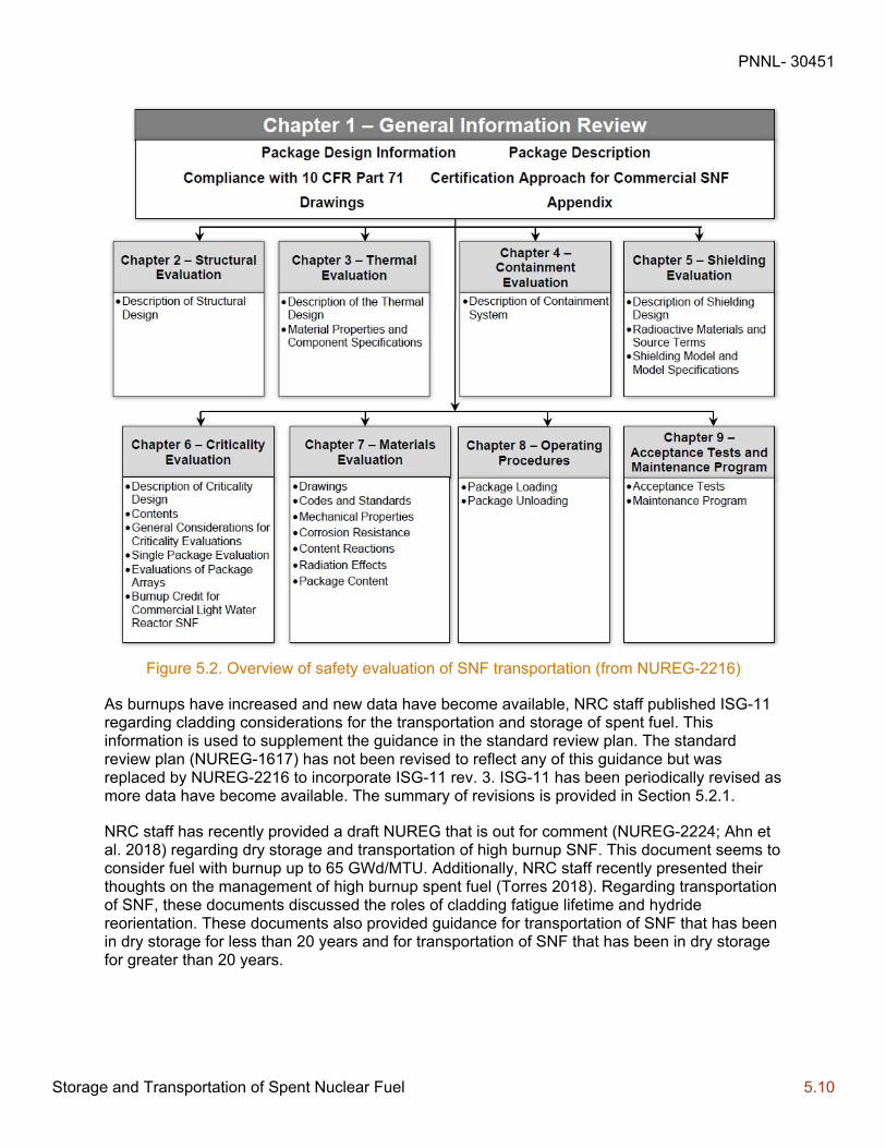
PNNL- 30451
Storage and Transportation of Spent Nuclear Fuel 5.10
Figure 5.2. Overview of safety evaluation of SNF transportation (from NUREG-2216)
As burnups have increased and new data have become available, NRC staff published ISG-11 regarding cladding considerations for the transportation and storage of spent fuel. This information is used to supplement the guidance in the standard review plan. The standard review plan (NUREG-1617) has not been revised to reflect any of this guidance but was replaced by NUREG-2216 to incorporate ISG-11 rev. 3. ISG-11 has been periodically revised as more data have become available. The summary of revisions is provided in Section 5.2.1.
NRC staff has recently provided a draft NUREG that is out for comment (NUREG-2224; Ahn et al. 2018) regarding dry storage and transportation of high burnup SNF. This document seems to consider fuel with burnup up to 65 GWd/MTU. Additionally, NRC staff recently presented their thoughts on the management of high burnup spent fuel (Torres 2018). Regarding transportation of SNF, these documents discussed the roles of cladding fatigue lifetime and hydride reorientation. These documents also provided guidance for transportation of SNF that has been in dry storage for less than 20 years and for transportation of SNF that has been in dry storage for greater than 20 years.
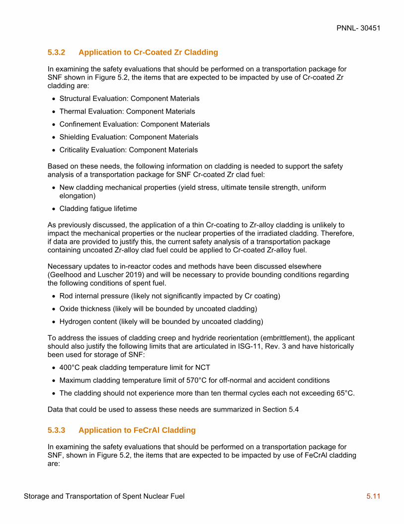
PNNL- 30451
Storage and Transportation of Spent Nuclear Fuel 5.11
5.3.2 Application to Cr-Coated Zr Cladding
In examining the safety evaluations that should be performed on a transportation package for SNF shown in Figure 5.2, the items that are expected to be impacted by use of Cr-coated Zr cladding are:
Structural Evaluation: Component Materials
Thermal Evaluation: Component Materials
Confinement Evaluation: Component Materials
Shielding Evaluation: Component Materials
Criticality Evaluation: Component Materials
Based on these needs, the following information on cladding is needed to support the safety analysis of a transportation package for SNF Cr-coated Zr clad fuel:
New cladding mechanical properties (yield stress, ultimate tensile strength, uniform elongation)
Cladding fatigue lifetime
As previously discussed, the application of a thin Cr-coating to Zr-alloy cladding is unlikely to impact the mechanical properties or the nuclear properties of the irradiated cladding. Therefore, if data are provided to justify this, the current safety analysis of a transportation package containing uncoated Zr-alloy clad fuel could be applied to Cr-coated Zr-alloy fuel.
Necessary updates to in-reactor codes and methods have been discussed elsewhere (Geelhood and Luscher 2019) and will be necessary to provide bounding conditions regarding the following conditions of spent fuel.
Rod internal pressure (likely not significantly impacted by Cr coating)
Oxide thickness (likely will be bounded by uncoated cladding)
Hydrogen content (likely will be bounded by uncoated cladding)
To address the issues of cladding creep and hydride reorientation (embrittlement), the applicant should also justify the following limits that are articulated in ISG-11, Rev. 3 and have historically been used for storage of SNF:
400°C peak cladding temperature limit for NCT
Maximum cladding temperature limit of 570°C for off-normal and accident conditions
The cladding should not experience more than ten thermal cycles each not exceeding 65°C.
Data that could be used to assess these needs are summarized in Section 5.4
5.3.3 Application to FeCrAl Cladding
In examining the safety evaluations that should be performed on a transportation package for SNF, shown in Figure 5.2, the items that are expected to be impacted by use of FeCrAl cladding are:

PNNL- 30451
Storage and Transportation of Spent Nuclear Fuel 5.12
Structural Evaluation: Component Materials, Dimensions, and Weights
Thermal Evaluation: Component Materials, Dimensions
Confinement Evaluation: Component Materials, Dimensions
Shielding Evaluation: Component Materials, Dimensions
Criticality Evaluation: Component Materials, Dimensions
Based on these needs, the following information on cladding is needed to support the safety analysis of a transportation package for SNF FeCrAl clad fuel:
New cladding mechanical properties (yield stress, ultimate tensile strength, uniform elongation)
New cladding thermal properties (thermal conductivity, specific heat, thermal expansion)
New cladding dimensions (FeCrAl cladding anticipated to be thinner than Zr-alloy cladding)
Cladding fatigue lifetime
FeCrAl activation following irradiation
FeCrAl neutron cross sections
Necessary updates to in-reactor codes and methods have been discussed elsewhere (Goodson and Geelhood 2020) and will be necessary to provide bounding conditions regarding the following conditions of spent fuel.
Rod internal pressure
Oxide thickness (likely will be minimal)
To address the issues of cladding creep and embrittlement, the applicant should also justify the following limits that are articulated in ISG-11, Rev. 3 and have historically been used for storage of SNF:
400°C peak cladding temperature limit for NCT
Maximum cladding temperature limit of 570°C for off-normal and accident conditions
The cladding should not experience more than ten thermal cycles each not exceeding 65°C
Data that could be used to assess these needs are summarized in Section 5.4.
5.4 Data Recommendation for Safety Evaluations
Based on the assessments in the previous sections, the information in Table 5.1 is needed to support safety analyses of a DSS and an SNF transportation package containing fuel with Cr-Coated Zr cladding or FeCrAl cladding. Also shown in this table are the recommended sources of information for each of these items.
Some data necessary to support this information may already be available. Section 6.0 discusses data that is currently available that could support the safety analysis of Cr-coated Zr and FeCrAl clad fuel for SNF storage and transportation.
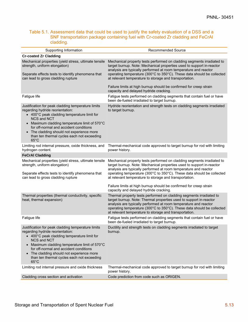
PNNL- 30451
Storage and Transportation of Spent Nuclear Fuel 5.13
Table 5.1. Assessment data that could be used to justify the safety evaluation of a DSS and a SNF transportation package containing fuel with Cr-coated Zr cladding and FeCrAl cladding.
Supporting Information Recommended Source
Cr-coated Zr Cladding
Mechanical properties (yield stress, ultimate tensile strength, uniform elongation) Separate effects tests to identify phenomena that can lead to gross cladding rupture
Mechanical property tests performed on cladding segments irradiated to target burnup. Note: Mechanical properties used to support in-reactor analysis are typically performed at room temperature and reactor operating temperature (300°C to 350°C). These data should be collected at relevant temperature to storage and transportation. Failure limits at high burnup should be confirmed for creep strain capacity and delayed hydride cracking.
Fatigue life Fatigue tests performed on cladding segments that contain fuel or have been de-fueled irradiated to target burnup.
Justification for peak cladding temperature limits regarding hydride reorientation:
400°C peak cladding temperature limit for NCS and NCT
Maximum cladding temperature limit of 570°C for off-normal and accident conditions
The cladding should not experience more than ten thermal cycles each not exceeding 65°C
Hydride reorientation and strength tests on cladding segments irradiated to target burnup.
Limiting rod internal pressure, oxide thickness, and hydrogen content.
Thermal-mechanical code approved to target burnup for rod with limiting power history.
FeCrAl Cladding
Mechanical properties (yield stress, ultimate tensile strength, uniform elongation) Separate effects tests to identify phenomena that can lead to gross cladding rupture
Mechanical property tests performed on cladding segments irradiated to target burnup. Note: Mechanical properties used to support in-reactor analysis are typically performed at room temperature and reactor operating temperature (300°C to 350°C). These data should be collected at relevant temperature to storage and transportation. Failure limits at high burnup should be confirmed for creep strain capacity and delayed hydride cracking.
Thermal properties (thermal conductivity, specific heat, thermal expansion)
Thermal property tests performed on cladding segments irradiated to target burnup. Note: Thermal properties used to support in-reactor analysis are typically performed at room temperature and reactor operating temperature (300°C to 350°C). These data should be collected at relevant temperature to storage and transportation.
Fatigue life Fatigue tests performed on cladding segments that contain fuel or have been de-fueled irradiated to target burnup.
Justification for peak cladding temperature limits regarding hydride reorientation:
400°C peak cladding temperature limit for NCS and NCT
Maximum cladding temperature limit of 570°C for off-normal and accident conditions
The cladding should not experience more than ten thermal cycles each not exceeding 65°C
Ductility and strength tests on cladding segments irradiated to target burnup.
Limiting rod internal pressure and oxide thickness Thermal-mechanical code approved to target burnup for rod with limiting power history.
Cladding cross section and activation Code prediction from code such as ORIGEN.

PNNL- 30451
Available Data 6.1
6.0 Available Data
This section describes the data that are currently available on Cr-coated Zr cladding and FeCrAl data in areas that have been identified for analysis of SNF storage and transportation. The presence of data in any area does not indicate that an applicant would not have to provide data from their specific coated cladding because it has been observed that coating processes and other processes can impact the performance of the cladding and the coatings. Rather, these data are compiled here to give the NRC staff expected performance of coated cladding, as well as areas of concern that should be given additional scrutiny, during the review of one of these concepts.
6.1 Cr-Coated Zr Cladding
The key data needed for analysis of SNF with Cr-coated Zr cladding during storage and transportation are cladding mechanical properties and cladding fatigue. The current available data for Cr-coated Zr cladding in these areas are discussed in the following sections.
6.1.1 Cladding Mechanical Properties
No data showing irradiated mechanical properties of Cr-coated Zr cladding has been found (elastic modulus, yield stress, and uniform elongation). Several sources of unirradiated mechanical properties of Cr-coated Zr have been found. The data are summarized in Table 6.1. In general, the results indicate that, in unirradiated conditions, the mechanical properties at room temperature and normal operating conditions are effectively not impacted by the application of a coating. The data also show that, in the unirradiated conditions, the coating can survive without crack significantly beyond 1% hoop strain. Irradiation causes a dramatic increase in strength and decrease in ductility in Zr-alloys (Geelhood, Beyer and Luscher 2008). For this reason, the impact of the Cr-coatings on the mechanical properties (elastic modulus, yield stress, and ductility) will need to be quantified with irradiated cladding data.
Table 6.1. Summary of unirradiated mechanical properties data for Cr-coated Zr cladding
Organization Cladding Test Description Results
Framatome (Brachet, et al. 2017)
Cr-coated M5® by PVD
Tensile tests at room temperature and 400°C Thermal creep at 400°C for 240 hours
Elastic modulus, yield stress, ultimate tensile strength and uniform elongation similar for coated and uncoated cladding. Thermal creep similar for coated and uncoated cladding.
KAERI (Kim, et al. 2015) Cr-coated Zry-4 by 3D laser coating
Ring tensile and ring compression tests
Elastic modulus, yield stress, ultimate tensile strength and uniform elongation similar for coated and uncoated cladding. No cracking observed at 2% or 4% hoop strain. Cracking observed at 6% strain.
MIT (Shahin, et al. 2018) Cr-coated Zry-4 by cold spray
Burst test at room temperature
Ultimate tensile strength, burst pressure, and burst strain about the same for coated and uncoated cladding.

PNNL- 30451
Available Data 6.2
6.1.2 Cladding Fatigue
There is little fatigue data for Cr-coated Zr. The data that do exist are for unirradiated Cr-coated Zr. The data are summarized in Table 6.2. For Zr-alloy cladding, the fatigue life has been shown to decrease with irradiation (O'Donnell and Langer 1964). The available data indicate that fatigue failure occurs significantly earlier in Cr-coated samples than in uncoated samples. The authors do note that this contrasts with previous data (Cavaliere and Silvello 2016). This indicates that process parameters and microstructure could have a profound impact on fatigue life. It has been noted (Kvedaras, et al. 2006) that in steels, Cr coating can improve or significantly worsen the fatigue lifetime due to different microstructures produced in the coating.
These data indicate a critical need for an applicant to provide fatigue data from irradiated cladding that they have manufactured to support their safety analysis limits.
Table 6.2. Summary of unirradiated fatigue data for Cr-coated Zr cladding.
Organization Cladding Test Description Results
MIT (Sevecek, et al. 2018)
Cr coated Zry by cold spray
Fatigue cycling in air and in water between 300°C and 312°C
Fatigue failure observed significantly earlier in Cr coated samples (~10,000 cycles) than uncoated samples (100,000 to 500,000) cycles
6.2 FeCrAl Cladding
The key data needed for analysis of SNF with FeCrAl cladding during storage and transportation are cladding mechanical properties, cladding thermal properties, and cladding fatigue. The current available data for FeCrAl cladding in these areas are discussed in the following sections.
6.2.1 Cladding Mechanical Properties
Mechanical properties of irradiated FeCrAl cladding have been studied and are summarized in Table 6.3. Irradiated rods should be investigated further as irradiation hardens the cladding and leads to significant increase in the yield stress and ultimate tensile strength. Fueled rods are preferable, as the in-reactor temperature and heat flux across the cladding can impact the competing creation and annealing of lattice defects that lead to this hardening and this temperature may be different for fueled and unfueled rods.

PNNL- 30451
Available Data 6.3
Table 6.3. Summary of mechanical property testing for irradiated FeCrAl cladding.
Lead FeCrAl Alloy(s)s Test Description Results
ORNL (Field et al. 2015)
Fe-10Cr-4.8Al Fe-12Cr-4.4Al Fe-15Cr-3.9Al Fe-18Cr-2.9Al
Tensile tests at room temperature (only one test per sample)
Room temperature engineering stress-strain curves
ORNL (Field et al. 2017)
F1C5AY Kanthal APMT
Tensile tests at room temperature and 320°C
Stress-strain curve, tensile response as a function of dose, 0.2% offset yield strength, ultimate tensile strength, uniform elongation, total elongation
ORNL (Chen et al. 2019)
C06M C36M
Vickers microhardness testing with 1 kg force and 15 s dwell time Transition fracture toughness testing
Master Curve transition temperature; reasonable linear correlation between the Master Curve fracture toughness transition temperature and Vickers microhardness
University of New Mexico (Zhang et al. 2020)
MA956 Tensile tests at room temperature
Yield stress, ultimate tensile strength, uniform elongation, total elongation; hardening and ductility reduction after irradiation were observed
Figure 6.1 shows the elastic modulus of Zr-based alloys (Geelhood et al. 2020) and various FeCrAl alloys (Field 2018; Kanthal 2019; Special Metals 2004).
Figure 6.1. Elastic modulus of Zr-based alloys (Geelhood et al. 2020) and various FeCrAl alloys (Field 2018; Kanthal 2019; Special Metals 2004).
The FeCrAl data were obtained from unirradiated samples. Currently no data from irradiated materials exist.
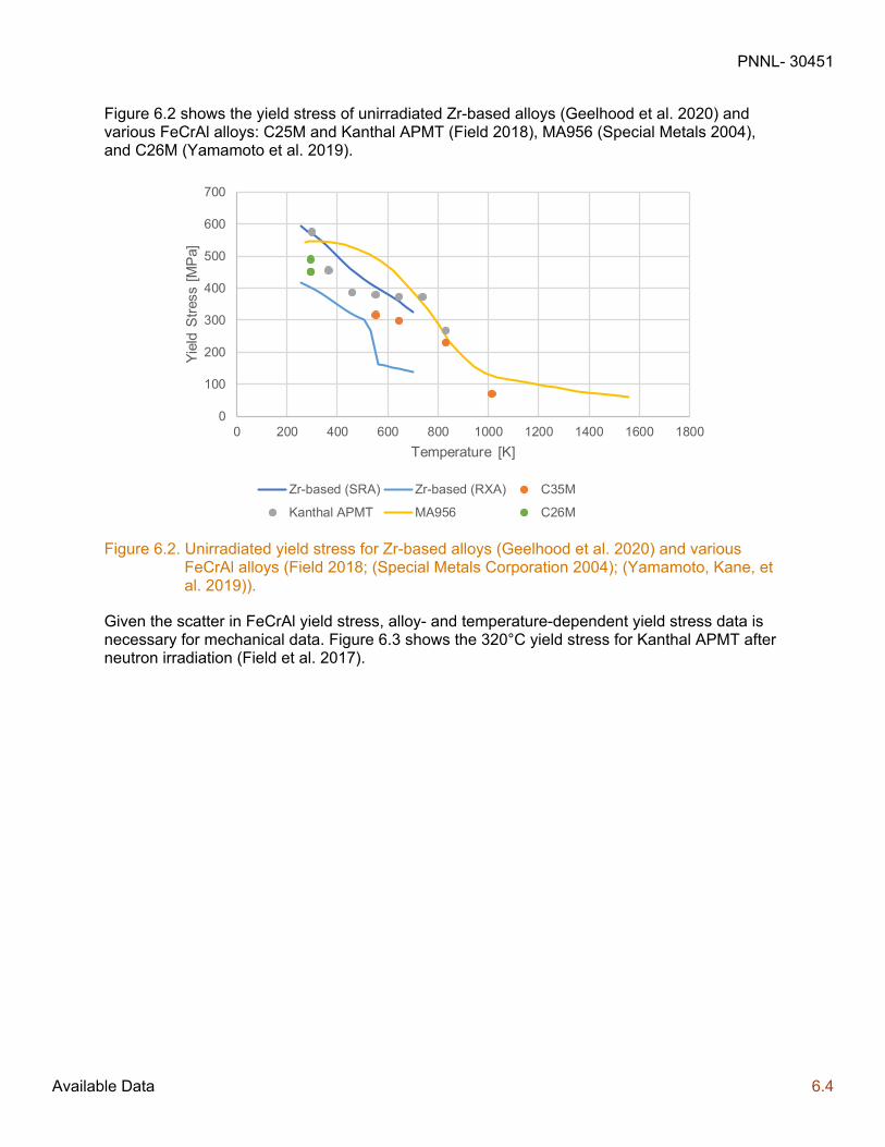
PNNL- 30451
Available Data 6.4
Figure 6.2 shows the yield stress of unirradiated Zr-based alloys (Geelhood et al. 2020) and various FeCrAl alloys: C25M and Kanthal APMT (Field 2018), MA956 (Special Metals 2004), and C26M (Yamamoto et al. 2019).
Figure 6.2. Unirradiated yield stress for Zr-based alloys (Geelhood et al. 2020) and various FeCrAl alloys (Field 2018; (Special Metals Corporation 2004); (Yamamoto, Kane, et al. 2019)).
Given the scatter in FeCrAl yield stress, alloy- and temperature-dependent yield stress data is necessary for mechanical data. Figure 6.3 shows the 320°C yield stress for Kanthal APMT after neutron irradiation (Field et al. 2017).
0
100
200
300
400
500
600
700
0 200 400 600 800 1000 1200 1400 1600 1800
Yie
ld S
tres
s [M
Pa]
Temperature [K]
Zr-based (SRA) Zr-based (RXA) C35M
Kanthal APMT MA956 C26M

PNNL- 30451
Available Data 6.5
Figure 6.3. Irradiated yield stress for Kanthal APMT at 320 °C (Field et al. 2017).
The yield stress of Kanthal APMT increases up to ~7 displacements per atom (dpa) and then saturation of the hardening occurs above this dose. Lower Cr-content variants of FeCrAl are less susceptible to brittle fracture above 7 dpa when irradiated at near LWR-relevant temperatures. Lower Cr-content variants maintain adequate mechanical performance in the context of tensile properties after neutron irradiation for ATF LWR cladding applications when compared to Zr-based alloys (Field et al. 2017).
6.2.2 Cladding Thermal Properties
Limited studies on the thermal properties of non-commercial FeCrAl alloys, especially lean-Cr content, have been completed. Table 6.4 summarizes these data.
Table 6.4. Summary of unirradiated thermal property testing for FeCrAl cladding.
Lead FeCrAl Alloy(s)s Test Description Results
ORNL (Field 2018) Kanthal APMT C06M C35M C36M
Differential scanning calorimetry, laser flash testing, dilatometry
Specific heat capacity, thermal diffusivity, thermal expansion
ORNL (Yamamoto et al. 2019)
C26M Dilatometry, differential scanning calorimetry, and laser flash testing
Thermal expansion, heat capacity, and thermal diffusivity
Figure 6.4 shows the thermal conductivity of Zr-based alloys (Geelhood et al. 2020) and various FeCrAl alloys (Field 2018; Special Metals 2004). This plot does not include C26M, but recent thermal diffusivity data (Yamamoto et al. 2019), used to determine thermal conductivity, indicates that C26M will have similar thermal conductivity to these other alloys.
0
100
200
300
400
500
600
700
800
900
1000
0 2 4 6 8 10 12 14 16
Yie
ld S
tres
s [M
Pa]
Damage Dose [dpa]
Kanthal APMT

PNNL- 30451
Available Data 6.6
Figure 6.4. Thermal conductivity of Zr-based alloys (Geelhood et al. 2020) and various FeCrAl alloys (Field 2018; Special Metals 2004).
The FeCrAl data (Field 2018) were collected from unirradiated samples and fit to a curve. Currently there are no data from irradiated samples.
Figure 6.5 shows the thermal expansion of Zr-based alloys (Geelhood et al. 2020) and various FeCrAl alloys (Field 2018; Yamamoto et al. 2019; Special Metals 2004). Zr-based alloy tubes are processed in such a way that the tubes exhibit a large degree of microstructural texture, which results in different thermal expansion in different directions (i.e., axial and circumferential). Recent data from C26M is included (Yamamoto et al. 2019) and shows good agreement with other FeCrAl alloys.
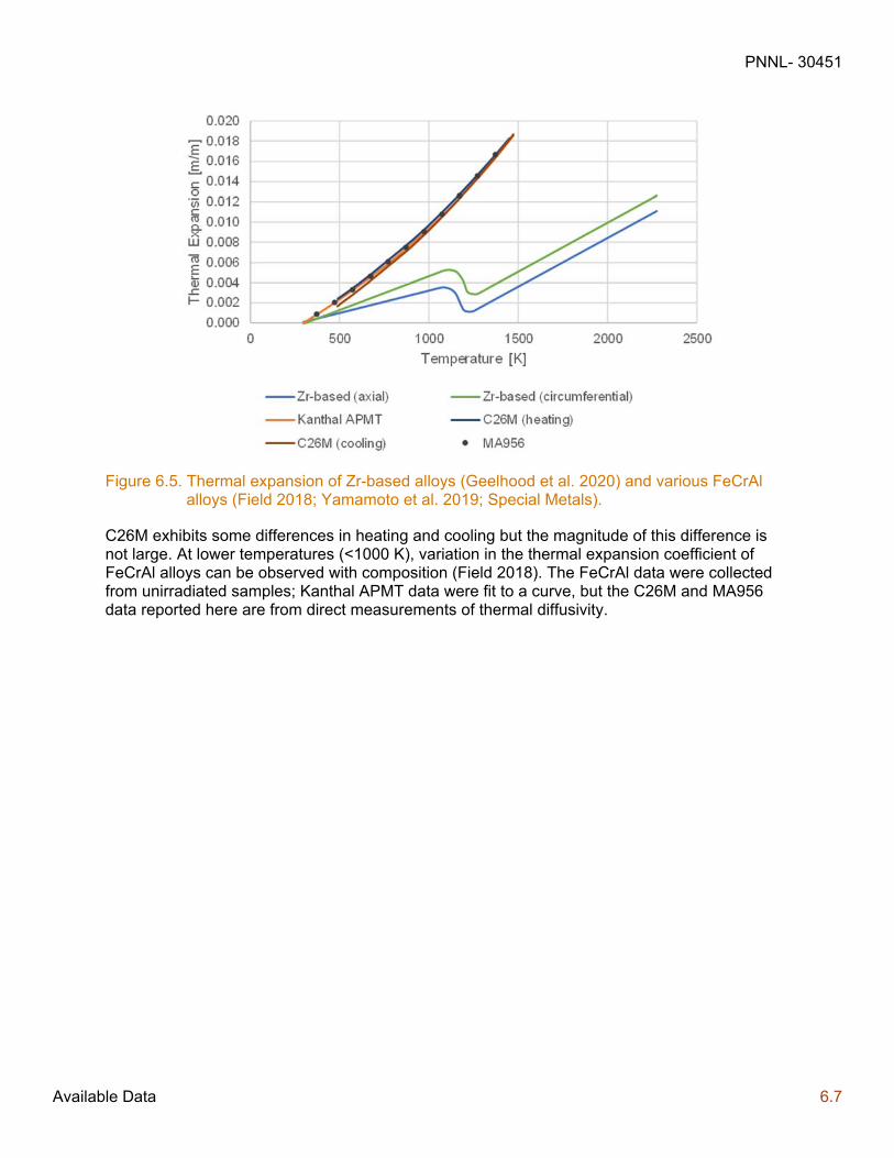
PNNL- 30451
Available Data 6.7
Figure 6.5. Thermal expansion of Zr-based alloys (Geelhood et al. 2020) and various FeCrAl alloys (Field 2018; Yamamoto et al. 2019; Special Metals).
C26M exhibits some differences in heating and cooling but the magnitude of this difference is not large. At lower temperatures (<1000 K), variation in the thermal expansion coefficient of FeCrAl alloys can be observed with composition (Field 2018). The FeCrAl data were collected from unirradiated samples; Kanthal APMT data were fit to a curve, but the C26M and MA956 data reported here are from direct measurements of thermal diffusivity.
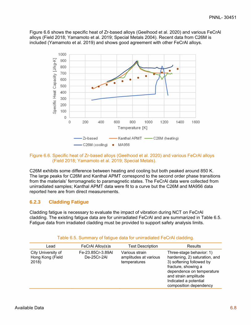
PNNL- 30451
Available Data 6.8
Figure 6.6 shows the specific heat of Zr-based alloys (Geelhood et al. 2020) and various FeCrAl alloys (Field 2018; Yamamoto et al. 2019; Special Metals 2004). Recent data from C26M is included (Yamamoto et al. 2019) and shows good agreement with other FeCrAl alloys.
Figure 6.6. Specific heat of Zr-based alloys (Geelhood et al. 2020) and various FeCrAl alloys (Field 2018; Yamamoto et al. 2019; Special Metals).
C26M exhibits some difference between heating and cooling but both peaked around 850 K. The large peaks for C26M and Kanthal APMT correspond to the second order phase transitions from the materials’ ferromagnetic to paramagnetic states. The FeCrAl data were collected from unirradiated samples; Kanthal APMT data were fit to a curve but the C26M and MA956 data reported here are from direct measurements.
6.2.3 Cladding Fatigue
Cladding fatigue is necessary to evaluate the impact of vibration during NCT on FeCrAl cladding. The existing fatigue data are for unirradiated FeCrAl and are summarized in Table 6.5. Fatigue data from irradiated cladding must be provided to support safety analysis limits.
Table 6.5. Summary of fatigue data for unirradiated FeCrAl cladding.
Lead FeCrAl Alloy(s)s Test Description Results
City University of Hong Kong (Field 2018)
Fe-23.85Cr-3.89Al De-25Cr-2Al
Various strain amplitudes at various temperatures
Three-stage behavior: 1) hardening, 2) saturation, and 3) softening followed by fracture, showing a dependence on temperature and strain amplitude Indicated a potential composition dependency
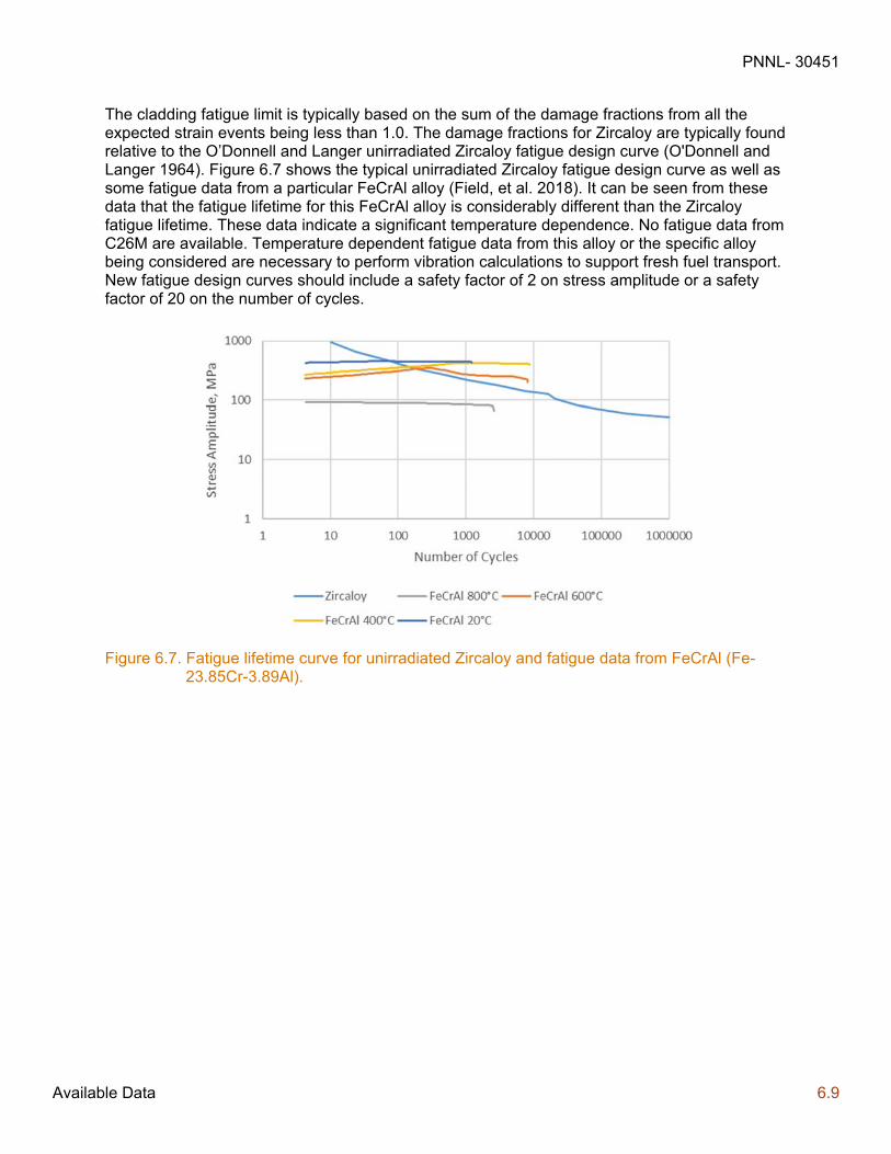
PNNL- 30451
Available Data 6.9
The cladding fatigue limit is typically based on the sum of the damage fractions from all the expected strain events being less than 1.0. The damage fractions for Zircaloy are typically found relative to the O’Donnell and Langer unirradiated Zircaloy fatigue design curve (O'Donnell and Langer 1964). Figure 6.7 shows the typical unirradiated Zircaloy fatigue design curve as well as some fatigue data from a particular FeCrAl alloy (Field, et al. 2018). It can be seen from these data that the fatigue lifetime for this FeCrAl alloy is considerably different than the Zircaloy fatigue lifetime. These data indicate a significant temperature dependence. No fatigue data from C26M are available. Temperature dependent fatigue data from this alloy or the specific alloy being considered are necessary to perform vibration calculations to support fresh fuel transport. New fatigue design curves should include a safety factor of 2 on stress amplitude or a safety factor of 20 on the number of cycles.
Figure 6.7. Fatigue lifetime curve for unirradiated Zircaloy and fatigue data from FeCrAl (Fe-23.85Cr-3.89Al).

PNNL- 30451
Conclusions 7.1
7.0 Conclusions
This report provides an assessment of the NRC regulatory structure for storage and transportation of SNF as it relates to near term ATF concepts, specifically Cr-coated Zr alloy and FeCrAl cladding. An overview of recent ATF development on these concepts is provided both with regard to what various organizations have recently published and general metallurgical background on these concepts including relevant cladding degradation and failure modes.
PNNL concludes that the current regulatory framework for SNF storage and transportation of fuel with these ATF claddings is generally applicable. However, applicants should provide data to justify the use of empirical temperature limits set in interim staff guidance and standard review plans if they wish to proceed with these limits.
Using the established framework, areas where cladding specific data will be necessary for each concept were identified.
For Cr-coated Zr cladding, the following data are needed:
Cladding mechanical properties (yield stress, ultimate tensile strength, uniform elongation)
Separate effects tests to identify phenomena that can lead to gross cladding rupture
Fatigue life
Justification for peak cladding temperature limits regarding hydride reorientation
For FeCrAl the following data are needed:
Mechanical properties (yield stress, ultimate tensile strength, uniform elongation)
Separate effects tests to identify phenomena that can lead to gross cladding rupture
Thermal properties (thermal conductivity, specific heat, thermal expansion)
Fatigue life
Justification for peak cladding temperature limits regarding hydride reorientation
Cladding cross section and activation
Additionally, for each concept, approved reactor codes should be used to provide limiting rod internal pressure and oxide thickness.
Finally, currently available data that are relevant to SNF storage and transport were identified for each cladding type. For both concepts there is limited representative irradiated data and it is expected that the applicants will provide additional data that is representative of the specific cladding they provide.
PNNL- 30451
References 8.0
8.0 References
Ahn, T., H. Akhavannik, G. Bjorkman, F.C. Chang, W. Reed, A. Rigato, D. Tang, R.D. Torres, B.H. White, and V. Wilson. 2018. Dry Storage and Transportation of High Burnup Spent Nuclear Fuel. NUREG-2224. Washington DC: US Nuclear Regulatory Commission.
Anders, A. 2008. Cathodic Arcs: From Fractal Spots to Energetic Condensation. New York: Springer-Verlag.
Arias, D, and J.P. Abriata. 1986. The Cr-Zr (Chromium-Zirconium) System. Bulletin of Alloy Phase Diagram. American Society for Metals: 237-244.
Avali, Raghu, and Edward Lahoda. 2018. Program Management Plan EnCore® Accident Tolerant Fuel (ATF) Program. GPEX-PMP-2018-000078.
Brachet, J.C., M. Dumerval, V. Lazaud-Chaillioux, M. Le Saux, E. Rouesne, S. Urvoy, P. Bossis, et al. 2017. "Behaviour of Enhanced Accident Tolerant Chromium Coated Zirconium Alloys Claddings." Enlarged Halden Programme Group 2017. Lillehammer, Norway: OECD Halden Reactor Project. F1.3.
Cavaliere, P., and A. Silvello. 2016. "Fatigue behaviour of cold sprayed metals and alloys: critical review." Surface Engineering 631-640.
Chen, Xiang, Kevin G. Field, Dalong Zhang, Caleb P. Massey, Kory D. Linton, Janet P. Robertson, and Andrew T. Nelson. 2019. Post-Irradiation Fracture Toughness Characterization of Generation II FeCrAl Alloys. ORNL/TM-2019/1391. Oak Ridge, TN: Oak Ridge National Laboratory.
EPRI. (2018). Coated Cladding Gap Analysis. 3002014603. Palo Alto, CA: EPRI.
EPRI. 2019. Accident-Tolerant Fuel Valuation: Safety and Economic Benefits (Revision 1). 3002015091. Palo Alto, CA: EPRI.
Fauchais, P.L., J.V.R. Heberlein, and M.I. Boulos. 2014. Thermal Spray Fundamentals: From Powder to Part. Boston, MA: Springer.
Fawcett, R. M. 2019. "GE/GNF ATF Program Update." EPRI/INL/DOE Joint Workshop on Accident Tolerant Fuel. Tampa, FL.
Field, K.G. 2018. Handbook on the Material Properties of FeCrAl Alloys for Nuclear Power Production Applications: FY18 Version, Revision 1.1. ORNL/SPR-2018/905. Oak Ridge, TN: Oak Ridge National Laboratory.
Field, Kevin G., Samuel A. Briggs, Kumar Sridharan, Richard H. Howard, and Yukinori Yamamoto. 2017. “Mechanical Properties of Neuron-Irradiated Model and Commercial FeCrAl Alloys.” Journal of Nuclear Materials 489: 118–28.
PNNL- 30451
References 8.1
Field, Kevin G., Xunxiang Hu, Kenneth C. Littrell, Yukinori Yamamoto, and Lance L. Snead. 2015. “Radiation Tolerance of Neutron-Irradiated Model Fe-Cr-Al Alloys.” Journal of Nuclear Materials 465: 746–55.
Field, K.G., M. Snead, Y. Yamamoto, and K. Terrani. 2018. Handbook on the Material Properties of FeCrAl Alloys for Nuclear Power Production Applications (FY18 Version: Revision 1.1. ORNL.SPR-2018/905, Rev. 1. Oak Ridge, TN: Oak Ridge National Laboratory.
Framatome. 2020. Framatome’s EATF Program. Accessed September 01, 2020. https://nextevolutionfuel.com/framatome-eatf-program/.
Gärtner, F., T. Stoltenhoff, T Schmidt, and H Kreye. 2006. "The Cold spray process and its potential for industrial applications." Journal of Thermal Spray Technology 223-232.
Geelhood, K.J., W.G. Luscher, I.E. Porter, L. Kyriazidis, C.E. Goodson, and E.E. Torres. 2020. MatLib-1.0: Nuclear Material Properties Library. PNNL-29728. Richland, WA: Pacific Northwest National Laboratory.
Geelhood, K.J., C.E. Beyer, and W.G. Luscher. 2008. PNNL Stress/Strain Correlation for Zircaloy. PNNL-17700. Richland, WA: Pacific Northwest National Laboratory.
Geelhood, K.J., and W.G. Luscher. 2019. Degradation and Failure Phenomena of Accident Tolerant Fuel Concepts: Chromium Coated Zirconium Alloy Cladding, PNNL-28437 Rev 1. Richland, WA: Pacific Northwest National Laboratory.
GNF. 2020. Global Nuclear Fuel Accident Tolerant Fuel Assemblies Installed in U.S. Plant. https://www.ge.com/news/press-releases/global-nuclear-fuel-accident-tolerant-fuel-assemblies-installed-us-plant.
Goldner, F., W. McCaughey, S. Hayes, D. Wachs, K. Terrani, A. Nelson, K. McClellan, and C. Stanek. 2019. "The U.S. Accident Tolerant Fuels Program - A National Initiative Coming of Age." TopFuel 2019. Seattle, Washington.
Goodson, C.E., and K.J. Geelhood. 2020. Degradation and Failure Phenomena of Accident Tolerant Fuel Concepts: FeCrAl Alloy Cladding. Richland, WA: Pacific Northwest National Laboratory.
Grainger, S. 1998. Engineering Coatings: design Application. Second Edition. Cambridge, England: Abington Publishing.
Hales, J.D. and K.A. Gamble 2015. "Preliminary Evaluation of FeCrAl Cladding and U-Si Fuel for Accident Tolerant Fuel Concepts." TopFuel 2015. Zurich, Switzerland: European Nuclear Society. A0069.
Harp, Jason M., Fabiola Cappia, and Luca Capriotti. 2018. Postirradiation Examination of the ATF-1 Experiments - 2018 Status: Rev. 0. INL/EXT-18-51497.
Jang, H. 2019. "ATF R&D Program Review in Korea." EPRI/INL/DOE Joint Workshop on Accident Tolerant Fuel. Tampa, FL.
PNNL- 30451
References 8.2
Kanthal. 2019. “Kanthal APMT Datasheet.” Sandvik AB. Hallstahammar, Sweden.
Karoutas, Z. 2019. "Westinghouse ATF Program Update." EPRI/INL/DOE Joint Workshop on Accident Tolerant Fuel. Tampa, FL.
Kim, H.-G., I.-H. Kim, Y.-I. Jung, D.-J. Park, J.-H. Park, Y.-H. Lee, and B.-K. Choi. 2019. "Status of ATF Cladding Development at KAERI." TopFuel 2019. Seattle, Washington.
Kim, H-G., I-H. Kim, Y-I. Jung, D-J. Park, J-Y. Park, and Y-H. Koo. 2015. "Adhesion property and high-temperature oxidation behavior of Cr-coated Zircaloy-4 cladding tube prepared by 3D laser coating." Journal of Nuclear Materials 531-539.
Kimura, A., S. Yuzawa, K. Yamasaki, and K. Yabuuchi. 2018. "Welding Technology R&D of Japanese Accident Tolerant FeCrAl-ODS Fuel Claddings for BWRs (2)." TopFuel 2018. Prague, Czech Republic: European Nuclear Society.
Kvedaras, V, J. Vilys, V. Ciuplys, and A. Ciuplys. 2006. "Fatigue Strength of Chromium-Plated Steel." Materials Science 16-18.
Lahoda, Edward J., and Boylan, Frank A. 2019. Development of LWR Fuels with Enhanced Accident Tolerance: ATF Feasibility Analysis and Final Technical Report Deliverable for the Westinghouse Accident Tolerant Fuel Program. GATFT-19-004, Rev. 2. United States. United States. doi:10.2172/1511013. https://www.osti.gov/servlets/purl/1511013.
Liu, T., J. Li, R Zue, L. Li, D. Guo, Q. Zhang, and D. Xu. 2018. "The research on Accident Tolerant Fuel in CGN." TopFuel 2018. Prague, Czech Republic: European Nuclear Society. A0244.
Maier, B, H. Yeom, G Johnson, T. Dabney, J. Walters, and K. Sridharan. 2018. "Development of Cold Spray Coatings for Accident Tolerant Fuel Cladding in Light Water Reactors." Journal of Metallurgy 198-202.
Maier, B., H. Yeom, G. Johnson, T. Dabney, J. Walters, P. Xu, J. Romero, H. Shah, and K. Sridharan. 2019. "Development of Cold Spray Chromium Coatings for Improved Accident Tolerant Zirconium-alloy Cladding." Journal of Nuclear Materials 247-254.
O'Donnell, W., and B. Langer. 1964. "Fatigue Design Basis for Zircaloy Components." Nuclear Science and Engineering 1-12.
OECD-NEA. 2018. State-of-the-Art Report on Light Water Reactor Accident-Tolerant Fuels. Paris, France: Nuclear Energy Agency.
Pierson, H.O. 1999. Handbook of Chemical Vapor Deposition: Principles, Technology and Applications, Second Editions. Norcich, New York: William Andrew Publishing, LLC.
Raiman, Stephen S., Kevin G. Field, Raul B. Rebak, Yukinori Yamamoto, and Kurt A. Terrani. 2020. “Hydrothermal Corrosion of 2nd Generation FeCrAl Alloys for Accident Tolerant Fuel Cladding.” Journal of Nuclear Materials 536.
Randhawa, H. 1988. "Cathodic arc plasma deposition technology." Thin Solid Films 175-186.
PNNL- 30451
References 8.3
Rebak, Raul B., Kurt A. Terrani, and Russ M. Fawcett. 2016. “FeCrAl Alloys for Accident Tolerant Fuel Cladding in Light Water Reactors.” In ASME 2016 Pressure Vessels & Piping Conference.
Rebak, Raul B., Timothy B. Jurewicz, and Young-Jin Kim. 2017. “Oxidation Resistance of FeCrAl in Simulated BWR and PWR Water Chemistries.” Water Reactor Fuel Performance Meeting (WRFPM) 2017. Jeju Island, Korea.
Rebak, Raul B., V. K. Gupta, M. Brobnjak, D. J. Keck, and Evan Dolley. 2018a. "Versatile Oxide Films Protect FeCrAl Alloys Under Normal Operation and Accident Conditions in Light Water Power Reactors." JOM 70 (2).
Rebak, Raul B., V. K. Gupta, M. Brobnjak, D. J. Keck, and Evan Dolley. 2018b. “Overcoming Sensitization in Welds Using FeCrAl Alloys.” TopFuel 2018. Prague, Czech Republic: European Nuclear Society. A0193.
Rebak, Raul B., Timothy B. Jurewicz, Michael Larsen, and Kan Sakamoto. 2019. “Immersion Testing of FeCrAl Tubes Under Simulated Light Water Nuclear Reactor Normal Operation Conditions.” TopFuel 2019. Seattle, Washington.
Richardson, Kate, and Heather Medema. 2019. “Advanced Fuels Campaign 2019 Accomplishments.” INL/EXT 19-56259.
Robb, Kevin R., Michael Howell, and Larry J. Ott. 2018. “Design and Analysis of Oxidation Tests to Inform FeCrAl ATF Severe Accident Models.” ORNL/SPR-2018/893. Oak Ridge, TN: Oak Ridge National Laboratory.
Sakamoto, K., Y. Miura, S. Ukai, A. Kimura, A. Yamaji, K. Kusagaya, and S. Yamashita. 2019. "Recent Progress in Development of Accident Tolerant FeCrAl-ODS Fuel Claddings for BWRs in Japan." TopFuel 2018. Prague, Czech Republic: European Nuclear Society.
Sato, T., F. Nakahara, F. Ueno, S. Yamashita, and K. Sakamoto. 2018. "Effects of Dissolved Oxygen and Ion Irradiation on the Corrosion of FeCrAl-ODS in High-Temperature Water Simulating BWR Operating Conditions." TopFuel 2018. Prague, Czech Republic: European Nuclear Society. A0083.
Schuster, Michael, Cole Crawford, and Raul B. Rebak. 2017. “Fresh Water Quenching of Alloys of Nuclear Interest Including FeCrAl for Accident Tolerant Fuel Cladding.” Water Reactor Fuel Performance Meeting (WRFPM) 2017. Jeju Island, Korea.
Sevecek, M., J. Krejci, M.H. Shahin, J. Petrik, R. Ballinger, and K Shirvan. 2018. "Fatigue Behavior of Cold Spray-Coated Accident Tolerant Cladding." TopFuel 2018. Prague, Czech Republic: European Nuclear Society. A0126.
Shahin, M., J. Petrik, A. Seshadri, B. Phillips, and K. Shirvan. 2018. "Experimental Investigation of Cold-Spray Chromium Cladding." TopFuel 2018. Prague, Czech Republic: European Nuclear Society. A0193.
Special Metals Corporation. 2004. INCOLOY® alloy MA956.
PNNL- 30451
References 8.4
Sweeney, W.E., and A.P. Batt. 1964. "Electron Proble and X-ray Diffraction Measurements of Intermediate Phases in Zr Diffused with Cr, Fe, Ni, Cu and Mo." Journal of Nuclear Materials 87-91.
Stuckert, J., Mirco Grosse, Martin Steinbrück, and Kurt A. Terrani. 2019. “Results of the Bundle Test QUENCH-19 with FeCrAl Claddings.” TopFuel 2019. Seattle, Washington.
Szőke, R., M. McGrath, and P. Bennet. 2017. "Dimensional Behaviour Testing of Accident Tolerant Fuel (ATF) In the Halden Reactor." Water Reactor Fuel Performance Meeting (WRFPM) 2017. Jeju Island, Korea.
Takahatake, Y., H. Ambai, Y. Sano, M. Takeuchi, K. Koizumi, K. Sakamoto, and S. Yamashita. 2018. "Corrosion Behaviour of FeCrAl-ODS Steels in Nitric Acid Solutions with Several Temperatures." TopFuel 2018. Prague, Czech Republic: European Nuclear Society.
Terrani, K. 2018. "Accident tolerant fuel cladding development: Promise, status, and challenges." Journal of Nuclear Materials 13-30.
Torres, R. 2018. "Spent Fuel Management: High Burnup." 33rd INMM Spent Fuel Management Seminar. Alexandria, VA: Institute of Nuclear Materials Management.
U.S. Congress. 2011. "Energy and Water Development Appropriations Bill, 2012: To Accompany H.R. 2345." S. Rep 112-75.
US Nuclear Regulatory Commission. 2000. Standard Review Plan for Spent Fuel Dry Storage Facilities, NUREG-1567. Washington DC: US Nuclear Regulatory Commission.
US Nuclear Regulatory Commission. 2000. Standard Review Plan for Transportation Packages for Spent Nuclear Fuel, NUREG-1617. Washington DC: US Nuclear Regulatory Commission.
US Nuclear Regulatory Commission. 2010. Standard Review Plan for Spent Fuel Dry Storage Systems at a General License Facility, NUREG-1536. Washington DC: Nuclear Regulatory Commission.
US Nuclear Regulatory Commission. 2015. Title 10 Code of Federal Regulations Part 71 Packaging and Transportation of Radioactive Material. Washington DC: US Nuclear Regulatory Commission.
US Nuclear Regulatory Commission. 2015. Title 10 Code of Federal Regulations Part 72 Licensing Requirements for the Independent Storage of Spent Nuclear Fuel, High-Level Radioactive Waste, and Reactor-Related Greater Than Class C Waste. Washington DC: US Nuclear Regulatory Commission.
US Nuclear Regulatory Commission. 2017. Title 10 Code of Federal Regulations Part 50 Domestic Licensing of Production and Utilization Facilities. Washington DC: US Nuclear Regulatory Commission.
US Nuclear Regulatory Commission. 2019. Managing Aging Processes In Storage (MAPS) Report, NUREG-2214. Washington DC: US Nuclear Regulatory Commission.

PNNL- 30451
References 8.5
US Nuclear Regulatory Commission. 2020a. Standard Review Plan for Spent Fuel Dry Storage Systems and Facilities, NUREG-2215. Washington DC: US Nuclear Regulatory Commission.
US Nuclear Regulatory Commission. 2020b. Standard Review Plan for Transportation Packages for Spent Fuel and Radioactive Material, NUREG-2216. Washington DC: US Nuclear Regulatory Commission.
Wang, Peng, Slavica Grdanovska, David M. Bartels, and Gary S. Was. 2020. “Effect of Radiation Damage and Water Radiolysis on Corrosion of FeCrAl Alloys in Hydrogenated Water.” Journal of Nuclear Materials 533.
Wenxin, X., and Y. Shihao. 2001. Reaction Diffusion in Chromium-Zircaloy-2 System, CNIC-01562. Chengdu: Nuclear Power Institute of China.
Westinghouse Nuclear. 2019. "EnCore® Fuel: We're Changing Nuclear Energy … Again." Accessed 2020. https://www.westinghousenuclear.com/Portals/0/about/stories/2017/Encore_fuel_brochure_8_pager_062819.pdf?ver=2019-07-09-192913-707.
Wukusick, C. S. 1966. The Physical Metallurgy and Oxidation Behavior of Fe-Cr-Al-Y Alloys. Cincinnati, OH.
Yamamoto, Y, K Field, B Pint, R Rebak, and R Fawcett. 2020. "Development of Nuclear Grade Wrought FeCrAl Alloys for Accident Tolerant Fuel Cladding." TMS 2020 149th Annual Meeting and Exhibition. San Diego, CA: TMS.
Yamamoto, Y, K Kane, B Pint, A Trofimov, and H Wang. 2019. Report on Exploration of New FeCrAl Heat Variants with Improved Properties, ORNL/TM-2019/1290. Oak Ridge, TN: Oak Ridge National Laboratory.
Yamashita, S., I. Ioka, Y. Nemoto, T. Kawanishi, M. Kurata, Y. Kaji, T. Fukahori, et al. 2019. "Overview of Accident-Tolerant Fuel R&D Program in Japan." TopFuel 2019. Seattle, Washington.
Yang, J., K. Hyun-Gil, D. Kim, C. Shin, and W. Kim. 2019. "Advances in ATF R&D at KAERI." EPRI/INL/DOE Joint Workshop on Accident Tolerant Fuel. Tampa, FL.
Yano, Y., T. Tanno, H. Oka, S. Ohtsuka, T. Inoue, S. Kato, T. Furukawa et al. 2017. “Ultra-High Temperature Tensile Properties of ODS Steel Claddings Under Severe Accident Conditions.” Journal of Nuclear Materials (487): 229–37.
Yeom, H., T. Dabney, G. Johnson, B. Maier, M. Lenling, and K. Sridharan. 2019. "Improving Deposition Efficiency in Cold Spraying Chromium Coatings by Powder Annealing." The International Journal of Advanced Manufacturing Technology 1373-1382.
Zhang, Zhexian, Tarik A. Saleh, Stuart A. Maloy, and Osman Anderoglu. 2020. “Microstructure Evolution in MA956 Neutron Irradiated in ATR at 328 °C to 4.36 Dpa.” Journal of Nuclear Materials 533.

PNNL- 30451
[Category]
Pacific Northwest National Laboratory 902 Battelle Boulevard P.O. Box 999 Richland, WA 99354 1-888-375-PNNL (7665)
www.pnnl.gov | www.nrc.gov