
Usage of Ansoft/HFSS simulation tool in mobile device development Jari Jekkonen.
Speeding up the HFSS 3D simulation design cyle using customisable scripting
Ansys UGM – 13th June 2013
Peter Jupp
Peak RF Ltd

Copyright © Peak RF Limited 2013. All rights reserved. 13/06/2013
New Peak RF Office
We are recruiting….
www.peakrf.co.uk/careers
Copyright © Peak RF Limited 2013. All rights reserved. 13/06/2013
Abstract
Visual Basic scripts have been developed for Ansys HFSS. The scripts provide a fully automated method for importing and performing 3D HFSS simulations of .gds cell designs, applicable to both simple structures such as single spiral inductors, through to complex multi-chip modules. Using scripts to control the complete process of cell import, material and terminal port assignment, solve space air-box definition, analysis set-up, simulation and s-parameter export has had a major impact on productivity - the design cycle for a recent filter die has been reduced from several months to just a few weeks. Furthermore, the use of a simple FOR-NEXT loop in the code has allowed a rapid generation of simulation data for complete design libraries of capacitors and spiral inductors implemented on my customer's passive semiconductor process, a process that previously would have been very time consuming.
Copyright © Peak RF Limited 2013. All rights reserved. 13/06/2013
Overview
Scripts have been generated for Ansys HFSS and also AWR Microwave Office(MWO). The HFSS scripts can either be directly run from within the HFSS GUI environment (taking inputs from a pre-prepared .gds layout together with a text file – defining stack-up and simulation parameters), or be called from a MWO VBA script via the Microsoft COM interface. This presentation covers: • Implementation of MWO PDK – including “virtual” ports, PEC airbox etc • MWO passive cell GUI • Simulation control text file • HFSS import/ simulate VB script overview • Running HFSS script independently – for Monte Carlo analysis for example • Multi-chip Module HFSS simulation – automated .gds import into package, bondwire auto-generation, and simulation.
Copyright © Peak RF Limited 2013. All rights reserved. 13/06/2013
First steps
Building component layouts • Chip design layout is currently performed in the Cadence environment. • Ansys provide links from Cadence to HFSS, but in this case it was decided to duplicate the layout environment within AWR Microwave Office(MWO). Alternately other circuit simulator packages with a 2D layout capability such as Ansys Designer or Agilent ADS could have been used. MWO is available locally at Peak RF and additional custom layers can easily be added in this environment.
Task The first task is to implement the semiconductor layer stack – essentially implementing a basic custom process design kit (pdk). .gds layers represent both physical layers – metals and dielectrics etc, together with virtual layers such as a PEC airbox, and ports. These layers will be recognised by the HFSS script.
Copyright © Peak RF Limited 2013. All rights reserved. 13/06/2013
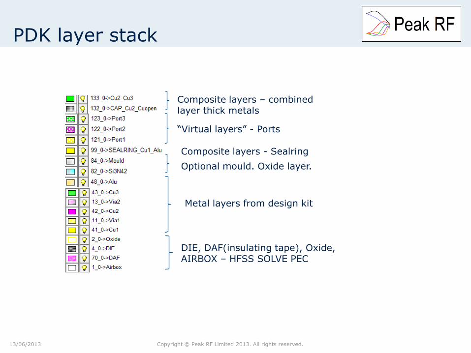
PDK layer stack
Composite layers – combined layer thick metals
“Virtual layers” - Ports
Composite layers - Sealring
Metal layers from design kit
DIE, DAF(insulating tape), Oxide, AIRBOX – HFSS SOLVE PEC
Optional mould. Oxide layer.
Copyright © Peak RF Limited 2013. All rights reserved. 13/06/2013
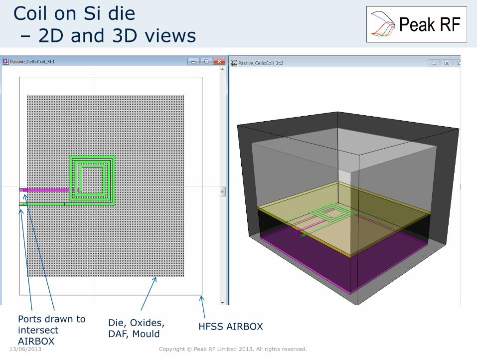
Coil on Si die – 2D and 3D views
HFSS AIRBOX Die, Oxides, DAF, Mould
Ports drawn to intersect AIRBOX
Copyright © Peak RF Limited 2013. All rights reserved. 13/06/2013
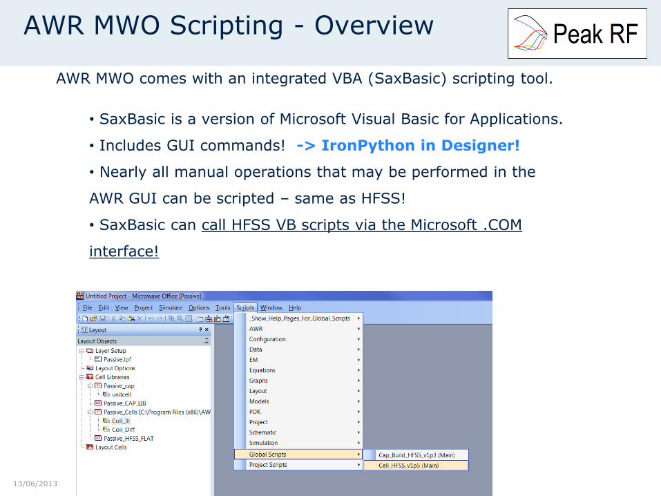
AWR MWO Scripting - Overview
AWR MWO comes with an integrated VBA (SaxBasic) scripting tool.
• SaxBasic is a version of Microsoft Visual Basic for Applications.
• Includes GUI commands! -> IronPython in Designer!
• Nearly all manual operations that may be performed in the
AWR GUI can be scripted – same as HFSS!
• SaxBasic can call HFSS VB scripts via the Microsoft .COM
interface!
Copyright © Peak RF Limited 2013. All rights reserved. 13/06/2013
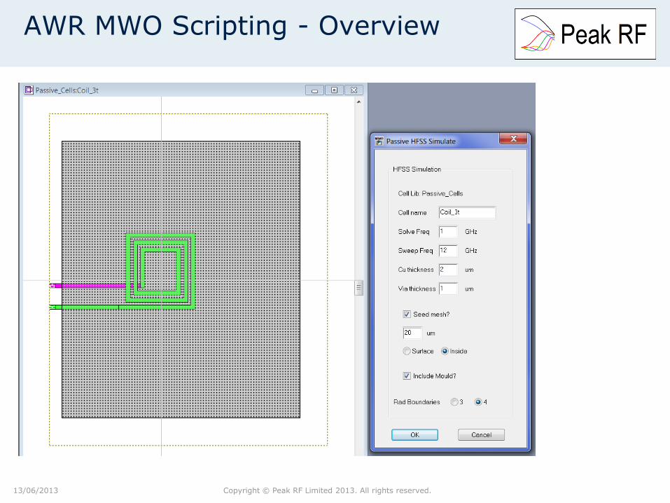
AWR MWO Scripting - Overview
Copyright © Peak RF Limited 2013. All rights reserved. 25/07/2012
Simulation control text file format
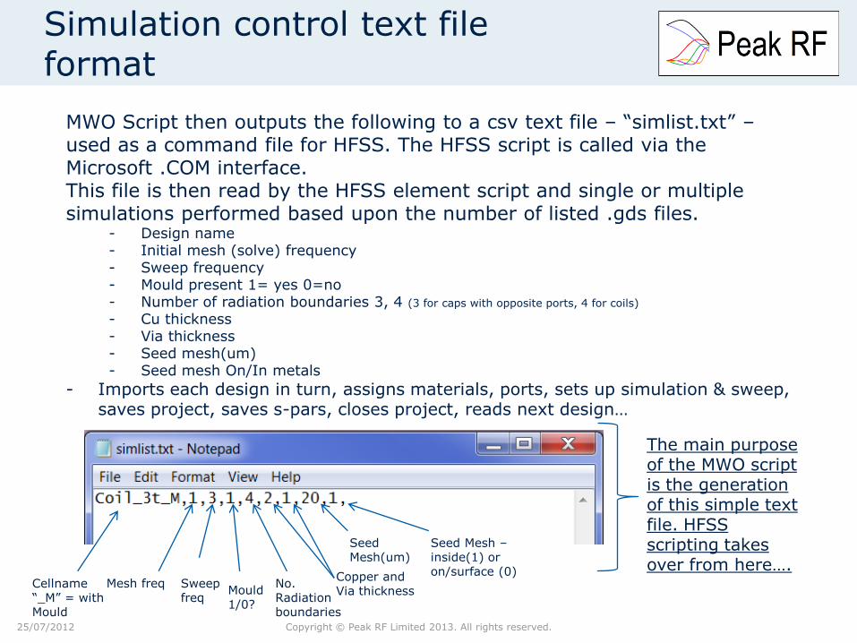
MWO Script then outputs the following to a csv text file – “simlist.txt” – used as a command file for HFSS. The HFSS script is called via the Microsoft .COM interface. This file is then read by the HFSS element script and single or multiple simulations performed based upon the number of listed .gds files.
- Design name - Initial mesh (solve) frequency - Sweep frequency - Mould present 1= yes 0=no - Number of radiation boundaries 3, 4 (3 for caps with opposite ports, 4 for coils)
- Cu thickness - Via thickness - Seed mesh(um) - Seed mesh On/In metals
- Imports each design in turn, assigns materials, ports, sets up simulation & sweep, saves project, saves s-pars, closes project, reads next design…
Mesh freq Sweep freq
Mould 1/0?
No. Radiation boundaries
Copper and Via thickness
Cellname “_M” = with Mould
Seed Mesh(um)
Seed Mesh – inside(1) or on/surface (0)
The main purpose of the MWO script is the generation of this simple text file. HFSS scripting takes over from here….
Copyright © Peak RF Limited 2013. All rights reserved. 13/06/2013
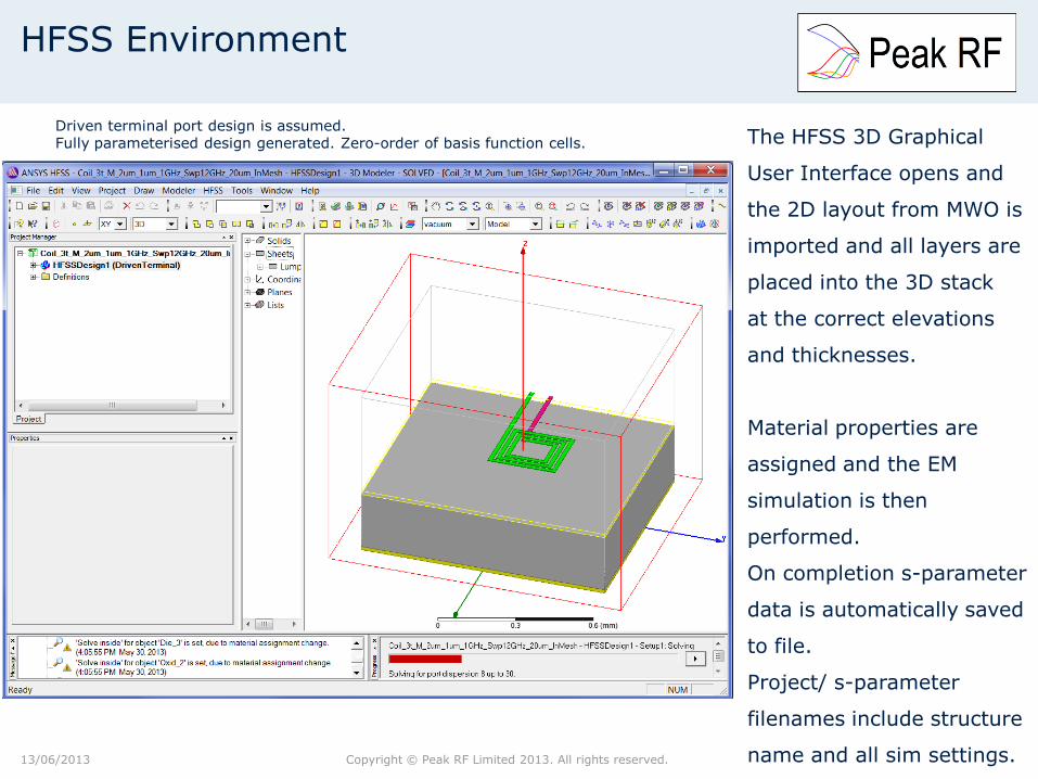
The HFSS 3D Graphical
User Interface opens and
the 2D layout from MWO is
imported and all layers are
placed into the 3D stack
at the correct elevations
and thicknesses.
Material properties are
assigned and the EM
simulation is then
performed.
On completion s-parameter
data is automatically saved
to file.
Project/ s-parameter
filenames include structure
name and all sim settings.
HFSS Environment
Driven terminal port design is assumed. Fully parameterised design generated. Zero-order of basis function cells.
Copyright © Peak RF Limited 2013. All rights reserved. 13/06/2013
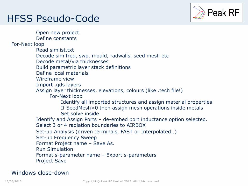
HFSS Pseudo-Code
Open new project Define constants For-Next loop Read simlist.txt Decode sim freq, swp, mould, radwalls, seed mesh etc Decode metal/via thicknesses Build parametric layer stack definitions Define local materials Wireframe view Import .gds layers Assign layer thicknesses, elevations, colours (like .tech file!) For-Next loop Identify all imported structures and assign material properties If SeedMesh>0 then assign mesh operations inside metals Set solve inside Identify and Assign Ports – de-embed port inductance option selected. Select 3 or 4 radiation boundaries to AIRBOX
Set-up Analysis (driven terminals, FAST or Interpolated..)
Set-up Frequency Sweep Format Project name – Save As. Run Simulation Format s-parameter name – Export s-parameters Project Save
Windows close-down
Copyright © Peak RF Limited 2013. All rights reserved. 13/06/2013
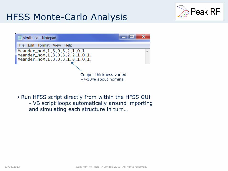
HFSS Monte-Carlo Analysis
Copper thickness varied +/-10% about nominal
• Run HFSS script directly from within the HFSS GUI - VB script loops automatically around importing and simulating each structure in turn…

Copyright © Peak RF Limited 2013. All rights reserved. 13/06/2013
HFSS Live Demos
Copyright © Peak RF Limited 2013. All rights reserved. 13/06/2013
Multi-chip Module Simulation
Uses pre-prepared “template” project system - template includes package, pcb and other die. - script loads template project, then requests user input to specify die .gds and bonding pattern - simulation is set-up, run and s-parameters exported. - Could be expanded to read simlist text file to enable Monte-Carlo sims.
HFSS DEMO – die in package – with bondwires
Copyright © Peak RF Limited 2013. All rights reserved. 13/06/2013
HFSS Live Demos
Copyright © Peak RF Limited 2013. All rights reserved. 13/06/2013
Conclusions
VBScripts have been written for HFSS and MWO. Running the HFSS script provides automated control of EM simulation for either simple on-chip designs, complete chip-mounted in package or alternatively batch simulation of multiple designs for Yield analysis purposes. Alternately running the MWO script allows more interactive control via GUI pop-up boxes and simulation of on-chip structures one at a time. The scripting approach has been proven in practice. The design cycle time for a recent product has been significantly reduced from months to a few weeks. Much of this time reduction was due to the automated design set-up. With the release of Ansys Designer – the intention is to port existing scripts across from MWO and HFSS into Designer and investigate the use of IronPython. Thanks to Oberdan Donadio and Dave Edgar for their assistance with my numerous scripting related questions!
Copyright © Peak RF Limited 2013. All rights reserved. 13/06/2013
Questions
Thank you for your attention.
Any questions please?


![슬라이드 1huniv.hongik.ac.kr/~wave/Lecture_board/2007_1/PATCH_… · PPT file · Web view... HFSS simulation HFSS [1] HFSS [2] HFSS [3] HFSS [4] HFSS [5] HFSS [6] HFSS [7] MICROSTRIP](https://static.fdocuments.net/doc/165x107/5a8896a37f8b9a001c8e9600/-wavelectureboard20071patchppt-fileweb-view-hfss-simulation.jpg)


