
Speed Sensors - HYDAC Technology Corporation
12
Speed Sensors
Transcript of Speed Sensors - HYDAC Technology Corporation

Speed Sensors

US
180.
000.
2/10
.17
1
10
SPEED SENSORS
The contact-free speed sensors of the HSS series detect the movement of ferromagnetic structures, such as gear wheels, gear rims or perforated discs, using the changes in magnetic flux.
Speed sensors for general applications:
Electronic Speed Sensor HSS 110
Electronic Speed Sensor HSS 120
Electronic Speed Sensor HSS 130
Electronic Speed Sensor HSS 210
Electronic Speed Sensor HSS 220

US
18.6
06.0
/10.
17
2
10
ElectronicSpeed SensorHSS 110
Description:The contact-free speed sensors of the HSS 110 series detect the movement of ferromagnetic structures, such as gear wheels, gear rims or perforated discs, using the changes in magnetic fl ux.So each sensor has two Hall elements and the differential between the two signals is detected, evaluated and then converted into an output signal suitable for processing.
For integration into standard controls, standard output signals are available.
Due to their extremely compact design, the robust housing and protection class IP 6K9K, the devices can be used in almost any application and any mounting position.
The main fi elds of application are detection of speed and rotation direction on gear wheels with small module and high resolution, especially in vehicles and mobile machines with electrical and hydraulic drives.
Special features:z1-channel Hall differential sensor
z Different signal outputs available
z Extremely compact design
z Wide frequency range
z Alignment required on installation
z Large air gap
Technical data:Input dataFrequency range NPN: 0.1 .. 20,000 Hz
PWM: 1.0 .. 5,000 Hz
Probe lengthProbe diameter
18.4 mm10.2 / 9.4 mm
Max. pressure on sensing surface 362.59 psi, static
Air gap / installation distance Module 1: 0.2 .. 0.8 mm Module 1.25: 0.2 .. 1.4 mm Module 1.5: 0.2 .. 1.8 mm Module 2: 0.2 .. 2.4 mm Module 3: 0.2 .. 2.9 mm
Mechanical connection Flange, single, asymmetrical, cable outlet 90°
Type of installation Dependent on direction(with asymmetrical fl ange)
Torque value max. 8 Nm
Housing materialSeal
Brass FPM
Output dataVariants 1-channel frequency
or1-channel frequency / direction of rotation(PWM)
Types 1 NPN frequency outputor1 PWM output, 4 .. 20 mA
Switching capacity / current rating NPN: ≤ 40 mAPWM: ≤ 200 mA
Direction of rotation Flange on left, gear turns to right,for duration of PWM signal pulse
Signal level LOW: ≤ 0.6 V / 4 .. 9 mA PWMHIGH: +UB / 12 ..17 mA PWM
Environmental conditionsOperating temperature range -40 .. +284 °FMedia resistance of housing Salt water; various hydraulic oils; diesel oils;
cleaning agent; salt spray
mark DIN EN 60947-5-2
Vibration resistance toEN 60068-2-64
0.05 g2 / Hz, 20 .. 2,000 Hz
Shock resistance toEN 60068-2-27
100 g, 6 ms, 3x in each direction
Protection class to IEC 60529to ISO 20653
IP 67IP 6K9K
Other data
Electrical connection Flying leads, 3-core, cable length 1 m
Supply voltage NPN: 12.5 .. 32 V DCPWM: 4.5 .. 20 V DC
Residual ripple of supply voltage ≤ 5 %Current consumption < 30 mA at 30 V DC
Average life expectancy 200,000 h (MTTF)
Weight ~ 50 g
Note: Reverse polarity protection of the supply voltage and short circuit protection (max. 50 mA) are provided.

US
18.6
06.0
/10.
17
3
10
Note:The information in this brochure relates to the operating conditions and applications described.For applications or operating conditions not described, please contact the relevant technical department.Subject to technical modifications.
HYDAC ELECTRONICS90 Southland Dr. Bethlehem, PA 18017Telephone +1 (610) 266-0100E-mail: [email protected]: www.hydacusa.com
Model code:
HSS 1 1 0 – X – 018 – 000
Pin connections:
Mounting position tolerance:
Specification for installation cavity:
Signal type 1 = Output 1: Frequency 4 = Output 1: Frequency and direction of rotation PWM
Probe length 018 = 18.4 mm
Modification number 000 = Standard
Dimensions:
Core HSS 110-1 HSS 110-4
red +UB +UB
black 0 V PWM
blue Frequency
±5
°
Ø 10.31 +0.0250
18.4 0-0.25
ø10
.2 0 -0
.2ø
9.4
±0
.1
M6
(18.6) 6
3.7
5.2
R7
(9)
Ø 10.31
8
1.8 15
°
13 +0.20
Ø 1
3.7
+0
.10
0
13 +0.20
6.1
+0
.20
7.1±0.2

US
18.6
07.0
/10.
17
4
10
ElectronicSpeed SensorHSS 120
Description:The contact-free speed sensors of the HSS 120 series detect the movement of ferromagnetic structures, such as gear wheels, gear rims or perforated discs, using the changes in magnetic fl ux.So each sensor has two Hall elements and the differential between the two signals is detected, evaluated and then converted into an output signal suitable for processing.
The instruments are available for different insertion depths. For integration into standard controls, standard output signals are available.
Due to their extremely compact design, the robust housing and protection class IP 69K, the instruments can be used in almost any application and any mounting position.
The main fi elds of application are detection of speed and rotation direction on gear wheels with a small module and high resolution, especially in vehicles and mobile machines with hydraulic drives.
Special features:z 2-channel Hall differential sensor
z Wide frequency range
z Alignment required when installing
z Large air gap
Technical data:Input dataFrequency range 0.1 .. 20,000 Hz
Probe lengthprobe diameter
30; 35; 45 mm15 / 12 mm
Max. pressure on sensing surface 217.55 psi, dynamic
Air gap / installation distance Probe length: 30 mm 35 / 45 mmModule 1: 0.2 .. 1.0 mm 0.2 .. 1.3 mmModule 1.25: 0.2 .. 1.5 mm 0.2 .. 1.8 mmModule 1.5: 0.2 .. 1.7 mm 0.2 .. 2.0 mmModule 2: 0.2 .. 2.2 mm 0.2 .. 2.5 mmModule 2.5: 0.2 .. 3.2 mm 0.2 .. 3.5 mm
Mechanical connection Flange, single, asymmetrical, cable outlet 90° (30 mm) / axial (35, 45 mm)
Type of installation Dependent on direction (with asymmetrical fl ange)
Torque value 10 Nm
Housing materialSeal
Brass FPM
Output dataVariant 2-channel speed
(90° / 270° phase shift for module 2)
Type 2 NPN frequency outputs
Switching capacity ≤ 50 mA≥ 10 kΩ ohmic load≤ 2.2 nF capacitive load
Direction of rotation Flange on left, gear turns to right:channel A lagging; channel B leading
Signal level LOW: ≤ 0.5 VHIGH: +UB
Environmental conditionsOperating temperature range -40 .. +284 °F
(-40 .. +320 °F for max. 500 operating hours)
Media resistance of housing Salt water; various hydraulic oils; diesel oils; cleaning agent; salt spray
mark DIN EN 60947-5-2
Vibration resistance toEN 60068-2-64
30 g, 10 .. 500 Hz, 100 min in each direction
Shock resistance toEN 60068-2-27 / -29
50 g, 11 ms, 3x in each direction 100 g, 6 ms, 3x in each direction
Protection class to IEC 60529to ISO 20653
IP 67IP 69K
Other data
Electrical connection Flying leads, 4-core, cable length 1 m
Supply voltage 7 .. 30 V DC
Residual ripple of supply voltage ≤ 5 %Current consumption < 30 mA at 30 V DC
Average life expectancy 200,000 h (MTTF)
Weight ~ 80 g
Note: Reverse polarity protection of the supply voltage and short circuit protection (max. 50 mA) are provided

US
18.6
07.0
/10.
17
5
10
Note:The information in this brochure relates to the operating conditions and applications described.For applications and operating conditions not described, please contact the relevant technical department.Subject to technical modifications.
HYDAC ELECTRONICS90 Southland Dr. Bethlehem, PA 18017Telephone +1 (610) 266-0100E-mail: [email protected]: www.hydacusa.com
Model code:
HSS 1 2 0 – 2 – XXX – 000
Pin connections:
Adjustment angle for other modules:
Specification for installation cavity:
Core HSS 120-2
brown +UB
blue Frequency 1 (A)
black 0 V
white Frequency 2 (B)
It is possible to achieve a 90° phase shift of the two frequency signals by turning the sensor through the angle indicated in the table below.
-20° Module 1
-15° Module 1.25
-10° Module 1.5
± 0° Module 2 ± 0°
Module 2.5 +15°
15
2.4
M620°
+10
12
12
35
Ø 1
5.1
Ø 15 HB
1.6
*
16.5
min
. 9
min
. 1.5
5
19.5
630
O-ring 11.8 x 1.8 FPM V80
O-ring 11.8 x 1.8 FPM V80
Ø 1
2
Ø 1
5
Ø 6.4
R 5.5
R 10.5
R 0
.4
R 0
.4
1,000 +50
Ø12 0-0.10
Ø 4
.7±0
.15
4.5
±0
.25
4.5
±0
.25
9±0
.25
9±0
.25
Ø15 0-0.10
0
15±0.1
* For sealing function RA 1.6,otherwise 3.2
Signal technology 2 = Outputs 1 and 2: Frequency (90° phase shift)
Probe length 030 = 30 mm 035 = 35 mm 045 = 45 mm
Modification number 000 = Standard
Dimensions:Probe length (A): 35 mm, 45 mm
Probe length: 30 mm
A

US
18.6
08.0
/10.
17
6
10
ElectronicSpeed SensorHSS 130
Description:The contact-free speed sensors of the HSS 130 series detect the movement of ferromagnetic structures, such as gear wheels, gear rims or perforated discs, using the changes in magnetic fl ux.So each sensor has two Hall elements and the differential between the two signals is detected, evaluated and then converted into an output signal suitable for processing.
The instruments are available in different insertion depths. For integration into standard controls, standard output signals are available.
Due to their extremely compact design, the robust housing and protection class IP 69K, the devices can be used in almost any application and any mounting position.
These devices are mainly used for detection of speed and rotation direction on rotary sensors, also under extreme environmental conditions.
Special features:z 2-channel Hall differential sensor
z Single-core seal
z Very high EMC resistance
z Large air gap
Technical data:Input dataFrequency range 0.1 .. 20,000 Hz
Probe lengthprobe diameter
16; 32 mm18 mm
Max. pressure on sensing surface 145.04 psi, dynamic
Air gap / installation distance Module 1: 0.2 .. 1.3 mmModule 1.25: 0.2 .. 1.8 mmModule 1.5: 0.2 .. 2.0 mmModule 2: 0.2 .. 2.5 mmModule 2.5: 0.2 .. 3.5 mm
Mechanical connection Double fl ange, asymmetrical, cable outlet at 90°
Type of installation Dependent on direction (with asymmetrical fl ange)
Torque value 10 Nm
Housing materialSeal
Brass / plastic (PA6 GF30)FPM
Output dataVariants 2-channel speed (90° phase shift)
or2-channel speed / direction of rotation
Types 2 NPN frequency outputs or1 NPN frequency output + 1 NPN direction of rotation output
Switching capacity ≤ 500 mA
Direction of rotation
Cable outlet at 90°, gear rotation to right:channel A leading; channel B laggingorrotational direction signal (right: HIGH / left: LOW)
Signal level LOW: ≤ 2 VHIGH: ≥ UB - 2 V
Environmental conditionsOperating temperature range -40 .. +257 °FMedia resistance of housing Saltwater, various hydraulic oils
mark DIN EN 60947-5-2
Vibration resistance toEN 60068-2-36
5 .. 57 Hz (1.5 mm p-p) 57 .. 2000 Hz (10 g)
Shock resistance toEN 60068-2-27
15 g, 11 ms, in each direction25 g, 6 ms, in each direction
Protection class to IEC 60529to ISO 20653
IP 67IP 6K9K
Other data
Electrical connection Flying leads, 4-core, 43 cm cable length
Supply voltage 8 .. 32 V DC
Residual ripple of supply voltage ≤ 5 %Current consumption < 33 mA at 24 V, both outputs LOW
< 23 mA at 24 V, both outputs HIGH
Average life expectancy 120,000 h (MTTF)
Weight ~ 110 g
Note: Reverse polarity protection of the supply voltage and short circuit protection are provided.
US
18.6
08.0
/10.
17
7
10
Note:The information in this brochure relates to the operating conditions and applications described.For applications and operating conditions not described, please contact the relevant technical department.Subject to technical modifications.
HYDAC ELECTRONICS90 Southland Dr. Bethlehem, PA 18017Telephone +1 (610) 266-0100E-mail: [email protected]: www.hydacusa.com
Model code:
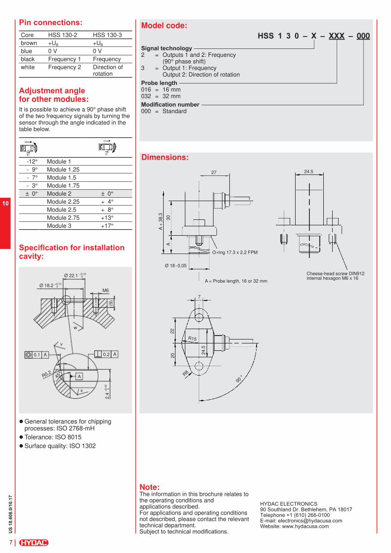
HSS 1 3 0 – X – XXX – 000
Signal technology 2 = Outputs 1 and 2: Frequency
(90° phase shift)3 = Output 1: Frequency
Output 2: Direction of rotation
Pin connections:
Adjustment angle for other modules:
Specification for installation cavity:
Probe length 016 = 16 mm 032 = 32 mm
Modification number 000 = Standard
Dimensions:
Core HSS 130-2 HSS 130-3
brown +UB +UB
blue 0 V 0 V
black Frequency 1 Frequency
white Frequency 2 Direction of rotation
It is possible to achieve a 90° phase shift of the two frequency signals by turning the sensor through the angle indicated in the table below.
-12° Module 1
- 9° Module 1.25
- 7° Module 1.5
- 3° Module 1.75
± 0° Module 2 ± 0°
Module 2.25 + 4°
Module 2.5 + 8°
Module 2.75 +13°
Module 3 +17°
24.5
Cheese-head screw DIN912 internal hexagon M6 x 16
A = Probe length, 16 or 32 mm
27
7
M6
0.1 A
w
v
x
A
A
0.2
90 °
R15
R8
24.5
30
22
A20
(9)
A +
38
.3
Ø 18 - 0.05
O-ring 17.3 x 2.2 FPM
z General tolerances for chippingprocesses: ISO 2768-mH
z Tolerance: ISO 8015
z Surface quality: ISO 1302
Ø 22.1 +0.100
Ø 18.2 +0.100
R0.245
°
2.4
+0
.40
0

US
18.6
09.0
/10.
17
8
10
ElectronicSpeed SensorHSS 210
Description:The contact-free speed sensors of the HSS 210 series detect the movement of ferromagnetic structures, such as gear wheels, gear rims or perforated discs, using the changes in magnetic fl ux.So each sensor has two Hall elements and the differential between the two signals is detected, evaluated and then converted into an output signal suitable for processing.
For integration into standard controls, standard output signals are available.
Due to their extremely compact design, the robust housing and protection class IP 67, the instruments can be used in almost any application and any mounting position.
The main fi elds of application are detection of speed and rotation direction on gear wheels with a small module and high resolution, especially in vehicles and mobile machines with hydraulic drives.
Special features:z 2-channel Hall differential sensor
z Wide frequency range
z Alignment required when installing
z Large air gap
z Simple installation
Technical data:Input dataFrequency range 0.1 .. 20,000 Hz
Installation depth 0 .. 50 mm adjustable
Max. pressure on sensing surface 72.52 psi, static / dynamic
Air gap / installation distance Module 1: 0.2 .. 1.0 mm Module 1.25: 0.2 .. 1.5 mm Module 1.5: 0.2 .. 1.7 mm Module 2: 0.2 .. 2.2 mm Module 2.5: 0.2 .. 3.2 mm
Mechanical connection Screw-in thread M12x1
Type of installation Dependent on direction
Torque value 13 Nm
Housing material Brass
Output dataVariants 2-channel speed (90° phase shift)
or2-channel speed / direction of rotation
Types 2 push-pull frequency outputs or1 push-pull frequency output + 1 push-pull direction of rotation output
Switching capacity ≤ 50 mA
Direction of rotationMarking on housing in direction of rotation, gear rotation to right: channel A leading; channel B laggingordirection of rotation signal(right: HIGH / left: LOW)
Signal level LOW: ≤ 2 VHIGH: ≥ UB - 2 V
Environmental conditionsOperating temperature range -40 .. +257 °FMedia resistance of housing Oils: HETG; HEES, HFD; HVLP; HLP
mark DIN EN 60947-5-2
Vibration resistance toEN 60068-2-64
0.05 g2/Hz, 20 .. 2,000 Hz
Shock resistance toEN 60068-2-27
30 g, 11 ms
Protection class to IEC 60529 IP 67(when an IP 67 female connector is used)
Other data
Electrical connection Male M12x1, 4 pole
Supply voltage 8 .. 30 V DC
Residual ripple of supply voltage ≤ 5 %Current consumption < 30 mA at 30 V DC
Average life expectancy 200,000 h (MTTF)
Weight ~ 40 g
Note: Reverse polarity protection of the supply voltage and short circuit protection are provided.

US
18.6
09.0
/10.
17
9
10
Note:The information in this brochure relates to the operating conditions and applications described.For applications and operating conditions not described, please contact the relevant technical department.Subject to technical modifications.
HYDAC ELECTRONICS90 Southland Dr. Bethlehem, PA 18017Telephone +1 (610) 266-0100E-mail: [email protected]: www.hydacusa.com
Model code:
HSS 2 1 0 – X – 050 – 000
Signal technology 2 = Outputs 1 and 2: Frequency
(90° phase shift)3 = Output 1: Frequency
Pin connections:
Output 2: Direction of rotation
Installation depth 050 = 50 mm max.
Modification number 000 = Standard
Dimensions:
M12x1, 4 pole
Pin HSS 210-2 HSS 210-3
1 +UB +UB
2 Frequency 1 (A) Frequency
3 0 V 0 V
4 Frequency 2 (B) Direction of rotation
Adjustment angle for other modules:It is possible to achieve a 90° phase shift of the two frequency signals by turning the sensor through the angle indicated in the table below.
Module 1 +15°
Module 1.25 +18°
Module 1.5 +23°
Module 2 +30°
Module 2.5 +38°
50Module 2
14
23
Key for alignment
Module 1
68
30 °
15 °
7.5
1.85
10
.4
M1
2x1
M1
2x1

US
18.6
10.0
/10.
17
10
10
ElectronicSpeed SensorHSS 220
Description:The contact-free speed sensors of the HSS 220 series detect the movement of ferromagnetic structures, such as gear wheels, gear rims or perforated discs, using the changes in magnetic fl ux.So each sensor has two Hall elements and the differential between the two signals is detected, evaluated and then converted into an output signal suitable for processing.
For integration into standard controls, standard output signals are available.
Due to their extremely compact design, the robust housing and protection class IP 68, the instruments can be used in almost any application and any mounting position.
The main fi elds of application are detection of speed and rotation direction on gear wheels with a small module and high resolution, especially in rail vehicles and mobile machines.
Special features:z 2-channel Hall differential sensor
z Wide frequency range
z Alignment required when installing
z Large air gap
z Simple installation
Technical data:Input dataFrequency range 0.1 .. 20,000 Hz
Installation depth 0 .. 46 mm adjustable
Max. pressure on sensing surface 145.04 psi, static
Air gap / installation distance Module 1: 0.2 .. 1.3 mm Module 1.25: 0.2 .. 1.8 mm Module 1.5: 0.2 .. 2.0 mm Module 2: 0.2 .. 2.5 mm Module 2.5: 0.2 .. 3.5 mm
Mechanical connection Screw-in thread M18x1
Type of installation Dependent on direction
Torque value 12 Nm
Housing material X12CrNiS18 8
Output dataVariants 2-channel speed (90° phase shift)
or2-channel speed / direction of rotation
Types 2 NPN frequency outputs or1 NPN frequency output + 1 NPN direction of rotation output
Switching capacity ≤ 50 mA (36 V, 257 °F, 50 % duty cycle) ≤ 500 mA (24 V, 77 °F, 50 % duty cycle)
Direction of rotation Marking on housing at 90° to rotational direction, gear rotation to right: channel A leading, channel B laggingordirection of rotation signal(right: HIGH / left: LOW)
Signal level LOW: ≤ 2 VHIGH: ≥ +UB - 2 V
Environmental conditionsOperating temperature range -40 .. +257 °FMedia resistance of housing Saltwater, various hydraulic oils
mark DIN EN 60947-5-2
Vibration resistance toEN 60068-2-6
15 g / 1 .. 2000 Hz
Shock resistance toEN 60068-2-27
30 g, 11 ms
Protection class to IEC 60529 IP 68 (when female connector is fi tted)Other data
Electrical connection Male M12x1, 4 pole
Supply voltage 8 .. 32 V DC
Residual ripple of supply voltage ≤ 5 %Current consumption < 33 mA at 24 V, both outputs LOW
< 23 mA at 24 V, both outputs HIGH
Average life expectancy 200,000 h (MTTF)
Weight ~ 80 g
Note: Reverse polarity protection of the supply voltage and short circuit protection are provided.

US
18.6
10.0
/10.
17
11
10
Note:The information in this brochure relates to the operating conditions and applications described.For applications and operating conditions not described, please contact the relevant technical department.Subject to technical modifications.
HYDAC ELECTRONICS90 Southland Dr. Bethlehem, PA 18017Telephone +1 (610) 266-0100E-mail: [email protected]: www.hydacusa.com
Model code:
HSS 2 2 0 – X – 046 – 000
Signal technology 2 = Outputs 1 and 2: Frequency
(90° phase shift)3 = Output 1: Frequency
Pin connections:
Output 2: Direction of rotation
Installation depth 046 = 46 mm max.
Modification number 000 = Standard
Dimensions:
M12x1, 4 pole
Pin HSS 220-2 HSS 220-3
1 +UB +UB
2 Frequency 2 Direction of rotation
3 0 V 0 V
4 Frequency 1 Frequency
Adjustment angle for other modules:It is possible to achieve a 90° phase shift of the two frequency signals by turning the sensor through the angle indicated in the table below.
-12° Module 1
- 9° Module 1.25
- 7° Module 1.5
- 3° Module 1.75
± 0° Module 2 ± 0°
Module 2.25 + 4°
Module 2.5 + 8°
Module 2.75 +13°
Module 3 +17°
M12x1
Ø 22
Ø 16.8
2
46
70
M18x1