SPEED e- NEWSLETTER · Rayat Shikshan Sanstha’s Yashwantrao Chavan Institute of Science, Satara....
11
SPEED e- NEWSLETTER Society for Promotion of Excellence in Electronics Discipline Glare The phenomenon called ‘Glare’ has been a matter of great interest in lighting from many years. Glare is the light which is very harmful to human being. It comes from oblique sources and enters the periphery of the eye thus increasing the background illumination and decreasing contrast. It causes visual fatigue and strain. The glare mainly depends on the background illumination and type of light source. As the luminance of the light source increases, the sensation of glare increases. As the background luminance increases, the sensation of glare decreases. Glare also depends on the size of the light source and even the age of the viewer. As the size of light source increases, the glare sensation increases until the source itself significantly influences the background luminance. The glare can be caused due to various types of luminaires such as High Mounted Headlamps, High Intensity Discharge Headlamps, HID Look-alike Bulbs, halogen lamps, Headlamps of the vehicles at night and LED lights. Nowadays, to save energy, most of the traditional lamps were replaced by the LED lamps. The potential for glare from any light source increases with greater lumen output and smaller source size, so as manufacturers strive for higher light output from smaller LED sources, the potential for glare to occur increases. Adoption of LEDs can be further harmful by increased glare potential. Linear fluorescent lamps are relatively large, diffuse light sources that are often used in locations which can be very sensitive to glare concerns. In some INSIDE THIS ISSUE Main Article 1 Events of Colleges 4 SPEED Activities 6 Cross Word Puzzle 9 Answer:Vol4,Issue1 11 locations even the switching from old T8 to newer T5 fluorescent lamps created glare issues because of the smaller surface area of the tubes. Editor Dr. Deepa Ramane Sinhgad College of Science, Ambegaon Pune - 411041. Contact Details: Phone: 020 -2425 3561 Mobile: +919921048350 Email: speednewsletters @gmail.com Volume 4, Issue 2 April 2016 Figure 1 Glare due to illumination system and reflection from computer screen The computer monitor itself is a source of light and can cause glare if the brightness and contrast controls are not properly adjusted. As shown in figure 1, light from the head mounted light sources (A and B) falls on the computer monitor and the reflection from it enters into eyes. If the orientation angle of the light source is not properly adjusted (light source C as shown in figure 1) then light can directly enters into the eyes. So, in the office workspace, glare due to computer screens and illumination systems must be addressed to increase the efficiency of the working people. Excessive daylight levels in interiors could produce excessive luminance range in the visual field with high risk of unwanted glare effects as shown in figure 2. Sunlight falling directly onto the working desk can cause glare.
Transcript of SPEED e- NEWSLETTER · Rayat Shikshan Sanstha’s Yashwantrao Chavan Institute of Science, Satara....

SPEED e- NEWSLETTER
Society for Promotion of Excellence in Electronics Discipline
Glare
The phenomenon called ‘Glare’ has
been a matter of great interest in lighting from
many years. Glare is the light which is very
harmful to human being. It comes from oblique
sources and enters the periphery of the eye thus
increasing the background illumination and
decreasing contrast. It causes visual fatigue and
strain. The glare mainly depends on the
background illumination and type of light source.
As the luminance of the light source increases,
the sensation of glare increases. As the
background luminance increases, the sensation
of glare decreases. Glare also depends on the
size of the light source and even the age of the
viewer. As the size of light source increases, the
glare sensation increases until the source itself
significantly influences the background
luminance. The glare can be caused due to
various types of luminaires such as High
Mounted Headlamps, High Intensity Discharge
Headlamps, HID Look-alike Bulbs, halogen lamps,
Headlamps of the vehicles at night and LED
lights.
Nowadays, to save energy, most of the
traditional lamps were replaced by the LED
lamps. The potential for glare from any light
source increases with greater lumen output and
smaller source size, so as manufacturers strive
for higher light output from smaller LED sources,
the potential for glare to occur increases.
Adoption of LEDs can be further harmful by
increased glare potential. Linear fluorescent
lamps are relatively large, diffuse light sources
that are often used in locations which can be
very sensitive to glare concerns. In some
I N S I D E T H I S I S S U E
Main Article 1
Events of Colleges 4
SPEED Activities 6
Cross Word Puzzle 9
A n s w e r : V o l 4 , I s s u e 1 1 1
locations even the switching from old T8
to newer T5 fluorescent lamps created
glare issues because of the smaller
surface area of the tubes.
Editor Dr. Deepa Ramane
Sinhgad College of
Science, Ambegaon
Pune - 411041.
Contact Details:
Phone:
020 -2425 3561
Mobile:
+919921048350
Email:
speednewsletters
@gmail.com
Volume 4, Issue 2
April 2016
Figure 1 Glare due to illumination system and
reflection from computer screen
The computer monitor itself is a source of
light and can cause glare if the brightness
and contrast controls are not properly
adjusted. As shown in figure 1, light from the
head mounted light sources (A and B) falls
on the computer monitor and the reflection
from it enters into eyes. If the orientation
angle of the light source is not properly
adjusted (light source C as shown in figure 1)
then light can directly enters into the eyes.
So, in the office workspace, glare due to
computer screens and illumination systems
must be addressed to increase the efficiency
of the working people.
Excessive daylight levels in interiors could
produce excessive luminance range in the
visual field with high risk of unwanted glare
effects as shown in figure 2. Sunlight falling
directly onto the working desk can cause
glare.

Page 2 SPEED e-Newsletter
Glare…
Figure 2 Glare due to excess daylight
The glare is experienced in different
spaces such as in auditorium, buildings,
office workspaces, laboratories, control
rooms etc. Commonly glare is used in
the context with automotive head
lamps, street lights and tunnel lighting.
However, glare caused due to indoor
illumination systems and also due to
daylight entering from windows should
be taken care and further reduced by
using available techniques.
Figure 3 Glare due to head lamps of vehicles
Figure 4 Glare due to illumination system of
auditorium and due to street lights
Figure 5 Glare due to big
screens/displays/monitors in control rooms
Definition of ‘Glare’:
Glare is defined as “the sensation
produced by luminance within the visual field
that is sufficiently greater than the luminance to
which eyes are adapted to cause annoyance,
discomfort or loss in visual performance and
visibility” [1].
Glare is also defined as visual condition under
which a feeling of discomfort and/or reduction
of perceptive abilities takes place [2]. Other
definitions of glare are “a course of visual
process accompanied by sensation of
discomfort or reducing ability to recognize
object [3] or as “a sensation caused by bright
areas in the field of view”. But despite the
definitional differences, these are always the
same factors and dependencies which affect
the occurrence of glare.
There are two basic types of glare: 1. Disability
glare 2. Discomfort glare
Figure 6 Disability Glare
Disability glare is caused by the light
scattered in the eye. This scattered light in
the eye lays a luminous veil over the retinal
image which reduces the contrasts in retinal
image. It is not necessarily associated with
physical comfort, but it is related to reduction
in visibility. The effect of disability glare
depends on the ambient light. Disability glare
may be well accounted for in terms of
scattering of light that result in a veiling
luminance. Disability glare can be really
troublesome in patients of cataract or after
Lasik correction. Disability glare can be
caused due to old age, Cataract, Posterior
Figure 7 Discomfort Glare
Discomfort glare often referred as
“psychological” because it constitutes a
serious source of hazards for
psychophysical health of the person.
Discomfort glare is a sensation of
annoyance or distraction caused by high
luminance in the field of view.
Discomfort glare occurs when the
illumination in visual field is much greater
than the level of illumination for which
retina is adapted. There is no standard
method to evaluate discomfort glare as it
is subjective and can vary from person to
person. Furthermore, the same person
will sometimes report different amount of
discomfort glare for the same light
source.

De Boer Value Perceived Glare
1 Unbearable
2
3 Disturbing
4
5 Just Permissible
6
7 Satisfactory
8
9 Barely
noticeable
Page 3 SPEED e-Newsletter
Glare…
.
Unified Glare Rating
Nowadays, other glare measurement system is
also used to evaluate discomfort glare such as
Visual Comfort Probability (VCP). The Visual
Comfort Probability (VCP) of a lighting system
is a rating that indicates the percentages of
people that will find a given discomfort glare
acceptable. Some of the other commonly
referred glare indices are BRS glare equation
(BRS or BGI), Cornell equation or daylight
glare index (DGI) and CIE Glare Index (CGI).
Researchers have attempted to quantify the
amount of discomfort glare ever since the
beginning of the previous century [6] but even
now, the physiological and psychophysical
mechanisms are not fully understood.
Recommendations to reduce glare:
The glare mainly depends on the type of light
source, its position in the space, its
orientation/fixture and background luminance.
As the disability glare is related to aspects of
Visual system , there is very little scope for
its reduction. However, discomfort glare
References: 1. Rea, Mark S. ed. 2000, The IESNA Lighting Handbook Reference and Application, Ninth Edition. New York: IESNA. 2. International Lighting Vocabulary CIE17.4 (1987). 3. EN 12665:2008, Light and lighting – Basic terms and criteria for determining the requirements for lighting (2008). 4. Alliance for Solid-State Illumination Systems and Technologies (ASSIST).A Method for Estimating Discomfort Glare from Exterior Lighting Systems. Troy, NY: Lighting Research Center, 2011. 6.CIE 117–1995. 7. Discomfort glare in interior lighting, 1995. p. 2–5.Luckiesh, M. and L.L 8..Holladay, Glare and Visibility. Transactions of the Illuminating Engineering Society,1925(20):p. 221-252.
Dr. Jayashree Bangali ,Head Electronics
Department, Kaveri college of Arts,
commerce and science , Pune-411038
Available Measuring techniques:
There is a growing consensus for the
need of evaluating glare due to indoor
illumination systems and day lit
commercial buildings. Disability glare
can be measured using a conventional
visual function test, usually acuity or
contrast-sensitivity, is administered in
the presence of a glare source.
Nowadays, there are various
evaluation methods of discomfort glare
are available, however, there remains a
lack of practical tools to measure
discomfort glare in the field.
Discomfort glare is often measured
based on a subjective rating scale. A
nine-point, De Boer scale is most
widely used in the field of automotive
and public lighting [4]. De Boer and his
colleagues developed a multi-label
scale consisting of nine points with five
verbal descriptors. In 1975, the scale
introduced by De Boer is as follows:
A de Boer-like scale has been used in
many studies of interior lighting. However,
there is a possibility of getting false alarm of
glare because this rating forces the user to
give opinion within the scale as it does not
include a ‘No Glare’ option. Further, many
other researchers suggested various scales
to measure discomfort glare.
Today, for indoor environment, discomfort
glare is mostly evaluated using Unified
Glare Rating (UGR) system which was
recommended internationally by CIE [5].
UGR is the luminance from the lamps
divided by the background visible light
luminance from the room background.
Can be evaluated and further reduced by
available techniques.
Some of the common recommendations to
reduce glare are:
1. Control light source - place the light
source at a position so that the light will not
shine directly into the eyes or reflect into
them from any surface.
2. Diffuse the light - diffuse the lights with the
help of diffuser/lens, however, it can reduce
light intensity.
3. Change the surface – As glare can occur
because of reflecting light from shiny
surface, change the type of surface.
Increase the brightness of the area around
the glare source.
4. Place light fixture higher from the target
area and more on overhead to reduce glare.
5. Use several small low-intensity light
fixtures rather than one large high-intensity
fixture.
6. Use adjustable local lighting with
brightness controls.
The glare can directly affect the human
health, so it is very important to evaluate
and reduce the glare factor. The disability
glare can lead to decreasing visibility,
increasing reaction and recovery time. The
discomfort glare usually does not interfere
with normal vision but can exacerbate
visual impairments causing discomfort and
fatigue. People spend most of the time in
the offices and they prefer to live and work
with good quality of light distribution. So, for
any indoor workspace, glare has to be
considered in the lighting design, as it is
directly related to the work efficiency.

NEWS and EVENTS at COLLEGES
A One Day State Level Symposium on
“Emerging Trends in Electronics and Computer Science Technology”,
organized by Department of Electronics & Computer Science,
Rayat Shikshan Sanstha’s Yashwantrao Chavan Institute of Science, Satara.
Department of Electronics &Computer Science had organised “A one day state level symposium on
Emerging Trends in Electronics and Computer Science Technology – Tech ++ 2016 A Step to Success” on
Saturday, 02th January 2016. The key concept of this Symposium is to exchange the knowledge & technical skills
in the emerging areas of computer science and Electronics among students. The symposium began with a
welcome speech by Mr. J. A. Wagh, Coordinator of Tech++ 2016 and he has explained the theme of the
symposum. The symposium was inaugurated by Chief Guest & key note speaker Hon. Prof.Deepak Tatpuje,
(Satara Polytechnic,Satara). He expresses his views on different new technologies and guide students on
different apects of technology and said “Think Local but Act Global”. The Chairperson of inaugural function Hon.
Dr. K. G. Kanade, Principal, Y. C. I. S, Satara pointed out the key aspects of the symposium and newer
technologies.He had appealed to the students to explore their innovative ideas in the new era’s of technology and
be Tech- Smart.
A one day state level symposium includes Quiz Competition, Paper presentation, Poster Presentation &
Online programming skills sessions. Overall 450 students & faculty from different colleges and universities
(Solapur, Kolhapur, Pune) had participated in the symposium. The 60 students had been participated in Quiz
Competition, 40 students in Paper Presentation which covers the area E-waste, Network based , Mobile
technologies and Robotics etc. The 100 students had been participated in Poster Presentation which is focused
on Cloud Computing, Microcontroller Application, Mobile technologies, Networking technologies and Operating
system etc. 40 students had been participated in online programming.
The Valedictory function of this one day state level symposium had began with welcome speech by Mr.
J. A. Wagh, Coordinator of Tech++2016. The Chief Guest of valedictory function
Hon.Vice.Prin.Dr.H.V.Deshmukh (Vice Principal Y. C. I. S, Satara) had delivered valedictory speech and shared
his ideas related with current techonology and congratulated to prize winners. Hon.Vice. Prin. Dr. N.A. Ghanvat
(Vice Principal, Y. C. I. S, Satara ) delivered the presidential address. Mr. A. J. Pawar proposed vote of thanks.
Page 4
SPEED e-Newsletter Page 5
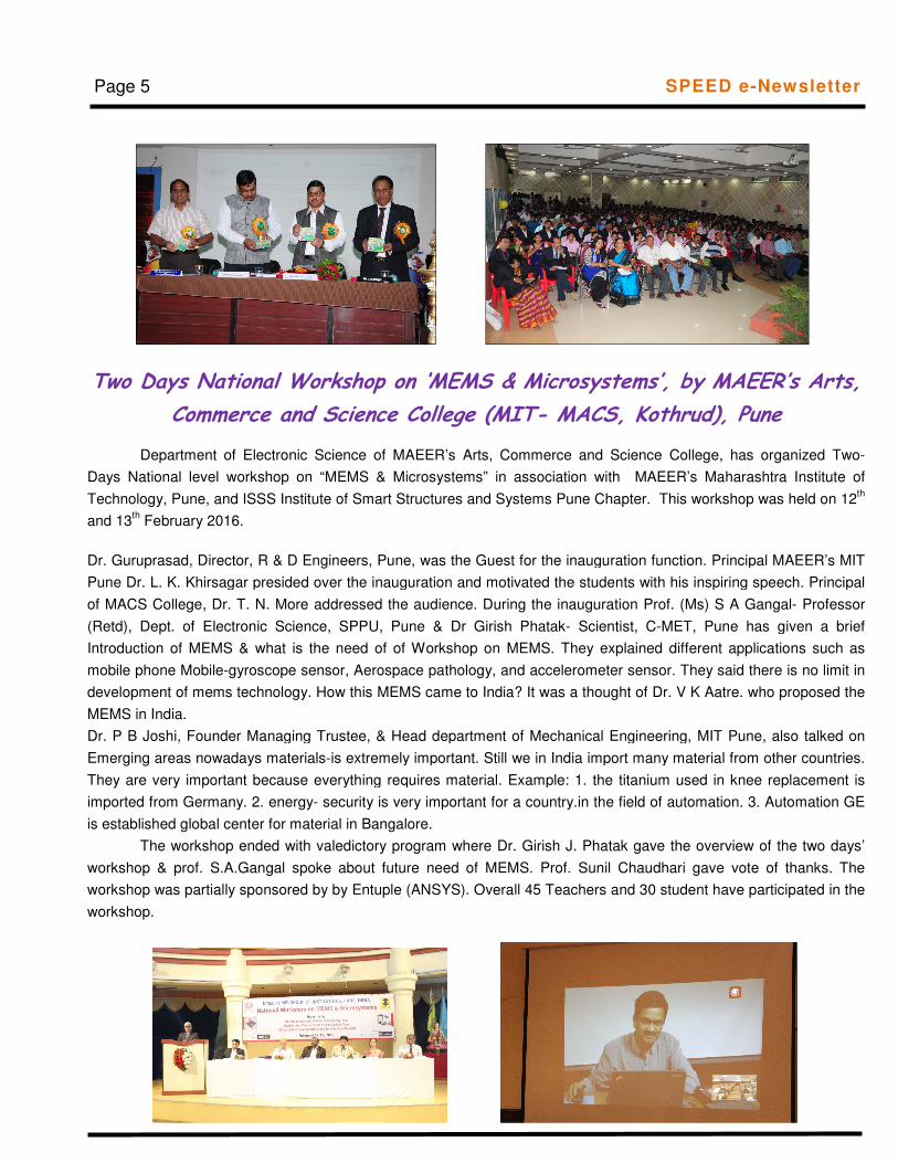
Two Days National Workshop on ‘MEMS & Microsystems’, by MAEER’s Arts,
Commerce and Science College (MIT- MACS, Kothrud), Pune
Department of Electronic Science of MAEER’s Arts, Commerce and Science College, has organized Two-
Days National level workshop on “MEMS & Microsystems” in association with MAEER’s Maharashtra Institute of
Technology, Pune, and ISSS Institute of Smart Structures and Systems Pune Chapter. This workshop was held on 12th
and 13th February 2016.
Dr. Guruprasad, Director, R & D Engineers, Pune, was the Guest for the inauguration function. Principal MAEER’s MIT
Pune Dr. L. K. Khirsagar presided over the inauguration and motivated the students with his inspiring speech. Principal
of MACS College, Dr. T. N. More addressed the audience. During the inauguration Prof. (Ms) S A Gangal- Professor
(Retd), Dept. of Electronic Science, SPPU, Pune & Dr Girish Phatak- Scientist, C-MET, Pune has given a brief
Introduction of MEMS & what is the need of of Workshop on MEMS. They explained different applications such as
mobile phone Mobile-gyroscope sensor, Aerospace pathology, and accelerometer sensor. They said there is no limit in
development of mems technology. How this MEMS came to India? It was a thought of Dr. V K Aatre. who proposed the
MEMS in India.
Dr. P B Joshi, Founder Managing Trustee, & Head department of Mechanical Engineering, MIT Pune, also talked on
Emerging areas nowadays materials-is extremely important. Still we in India import many material from other countries.
They are very important because everything requires material. Example: 1. the titanium used in knee replacement is
imported from Germany. 2. energy- security is very important for a country.in the field of automation. 3. Automation GE
is established global center for material in Bangalore.
The workshop ended with valedictory program where Dr. Girish J. Phatak gave the overview of the two days’
workshop & prof. S.A.Gangal spoke about future need of MEMS. Prof. Sunil Chaudhari gave vote of thanks. The
workshop was partially sponsored by by Entuple (ANSYS). Overall 45 Teachers and 30 student have participated in the
workshop.

** Workshop for students on ”Learning Through Demonstration”
Page 6
SPEED ACTIVITIES
One day workshop titled “Learning Through Demonstrations” was organized for T.Y.B.Sc.(Electronic Science)
students on Saturday 16th January 2016 by Department of Electronic Science, Abasaheb Garware College, Karve
Road, Pune in association with SPEED and IEEE India Chapter. The purpose of workshop was making students
aware of the different techniques available for easy learning process. About 95 students attended the workshop.
The workshop was inaugurated at the hands of Dr. A. D. Shaligram, Chairman, SPEED and Head, Department of
Electronic Science, Savitribai Phule Pune University, Pune. Dr. Shrikant Gupta, Principal, Abasaheb Garware
College, Pune, Dr. P. B. Buchade, Secretary, SPEED and Head, Department of Electronic Science, Abasaheb
Garware College, Pune and Dr. Supriya S. Patil, Co-coordinator of Workshop were also present at the
occasion.
The first session was on demonstration of “Applications of MATLAB and Simulink” by Mr. Ankur Divekar from
CloudMoyo, Pune. He demonstrated different aspects of MATLAB right from Plotting equations to System
modeling in simulink to Image Processing to wireless data acquisition via wifi. In the next session Dr.
A.D.Shaligram clarifies the doubts of the students on “Project: Thinking to Research”.
In post lunch session Prof. D. B. Gaikwad demonstrated the design flow for system building using CPLD’s and
FPGA’s. Next session by Dr.N. M. Kulkarni on “Sensors in Smart Phones” was completely interactive and
consisted of a number of demonstrations based on the Calibration and Utilization of sensors in his own Smart
Phone. In the next session by Mr. Henry and Mr. Ankush Shingade, representing Jam pot Photonics was on
“Present and Future of Optics”.
“Circuit Design and Simulation” was the topic of last session presented by Prof. Diwate. The session included a
number of demonstrations right from Practical level circuits to Project level circuits using Proteus software. The
workshop ended with the lecture on “Opportunities after B.Sc. Electronics” by Dr. P.B.Buchade, wherein he
explored all the career possibilities and opportunities available for graduates in Electronics.
SPEED e-Newsletter

“VIA_NE_Mation!15” Competition
The world of 3D is rapidly expanding, and career opportunities exist in a wide range of fields – including architecture,
games, product and industrial design, civil engineering, and short video films, films and television animation. Considering
this, the VIA_NE_MATION!15 competition was organised. This was the second year of this competition. The purpose of
this competition is to help the students to step into a real world production environment where the skills like creativity,
imaginative visualization capability, good understanding of the subject concepts are very important and the output must be
accomplished within specific time frames, resources and design constraints.
The “VIA_NE_Mation!15” Competition for the year 2015-16 was organized in February 2016. There was good response
from the students across a wide cross-section. Students from different streams and from Under graduate as well as Post
graduate sections participated in this competition.
The judges’ panel comprised of eminent teachers from different renowned colleges. The judges kindly agreed to spare
their valuable time and enthusiastically evaluated the submissions.
The Judges panel:
1. Dr. V. S. Kale (Principal, Arts, Commerce and Science College, Trimbakeshwar, Dist. Nasik)
2. Mr. R. K. Nerakar (Associate Professor, Dept. of Electronic Sc., Wadia College, Pune)
3. Mrs. Shubhangi Katti (Associate Professor, Dept. of Electronic Sc., Fergusson College, Pune)
4. Mr. P. S. Varade (Associate Professor, Dept. of Electronic Sc., Modern College, Pune)
2. Name: Trupti Ravindra Gaikwad
College: Modern College, Shivajinagar, Pune.
Topic: How Does Rain fall
Heartiest Congratulations to All the Winners and Participants.Heartiest Congratulations to All the Winners and Participants.Heartiest Congratulations to All the Winners and Participants.Heartiest Congratulations to All the Winners and Participants.
SPEED e-Newsletter
Name: Ojal Arun Shetty
College: Modern college of Arts Science & Commerce,
Shivaji Nagar, Pune.
Topic: "BE THE CHANGE"
1. Name: Tejas Prasad Ghate
College: M.E.S.'s Abasaheb Garware College, Pune
Topic: Intelligent Water Supply Monitoring & control system
First Prize
Consolation Prize
Page 7

SPEED EEE Examination was conducted in January and February 2016 at different colleges in
and around Puneand was coordinated by Dr. Supriya S. Patil. It was conducted at six different
centers viz. Abasaheb Garware college, Pune, Fergusson college, Pune, Modern College,
Shivajinagar Pune, T. C. College, Baramati, Sinhgad College, Pune and Kaveri College. In all 188
students attended this examination. 100 marks examination consists of 50 multiple choice questions
carrying 2 marks each. Students are awarded grades as O, A, B and C. Out of the 188 students,
182 students were qualified i.e result in 96%.
EEE SPEED exam Centre wise Toppers
Centre: Abasaheb Garware College, Karve Road, Pune
1. Namrata Kulkarni (S. Y. B. Sc.) & Kshitija Deshpande (S. Y. B. Sc.) 2 .Prayusha Mishra (F. Y. B. Sc.) & Sukanya Deo (F. Y. B. Sc.)
Centre: Kaveri College, Pune
1. Prachi Dabi (S. Y. B. Sc. Comp Sci.) 2. Ashwini Kulkarni (S. Y. B. Sc. Comp Sci.)
Centre: Modern College, Shivajinagar, Pune
1. Madhu Bharati (F. Y. B. Sc. Comp Sci.) 2. Seema Chaskar (S. Y. B. Sc.)
Centre: Sinhgad College of Science, Pune
1. Swati Sharma (F. Y. B. Sc. Comp Sci.) 2. Sharvari Wagh (F. Y. B. Sc. Comp Sci.)
Centre: T. C. College, Baramati
1. Supriya Moholkar (S. Y. B. Sc.) 2. Reshma Hambire (F. Y. B. Sc.)
Centre: Fergusson College, Pune
1. Swarnim Shirke (F. Y. B. Sc.) 2. Saurabh Patil (F. Y. B. Sc.)
Dr. (Mrs.) Deepa Ramane (Editor) [email protected] +9199210 48350
Prof. R. K. Nerkar [email protected] +9194235 81016
Prof. (Mrs.) Sapana Rane [email protected] +919890968884
Prof. Raghu Vidup [email protected] +919405235189
Prof. Sunil Chuadhari [email protected] +919422616727
Dr. Y. B. Gandole [email protected] +919421737928
Report of EEE SPEED examination 2015- 2016
SPEED e-Newsletter Page 8
Editorial team of SPEED e-Newsletter

1 2
3 4
5
6 7
8
9 10 11
12
13 14
15
16 17 18
19
20
21 22
23 24 25 26
27 28
EclipseCrossword.com
Page 9 SPEED e-Newsletter

Across
3. A counter is a ....... circuit. (10)
5. With most Monostable Multivibrators, when no inputs trigger occurred, the Q output is in........ state.
(3)
7. The 74121 nonretriggerable Multivibrator can have the output pulse set by a single external
component. This component is a (n)........ (9)
9. The ...... of a 555 timer configured as a basic Astable Multivibrator is controlled by a resistor and a
capacitor. (9)
10. A ....... circuit is not suitable in the synchronous circuit design because of its transparency nature. (5)
16. The normal ...... inputs to a Flip-flop are referred to as sequential inputs. (4)
19. Astable Multivibrator is also known as........ Multivibrator. (11)
20. A Multivibrator is a circuit that changes between two ...... levels on a continuous, free-running basis or
on demand. (7)
21. The 555 ...... can be used in either the Astable or Monostable modes. (5)
22. An Astable Multivibrator is sometimes referred to as a...... (5)
23. What type of Multivibrator is a latch? (8)
25. In sequential circuits, the output depends not only on the current inputs but also on the ...... input
values. (4)
27. ........ is a sequential circuit those cycles through a sequence of states. (7)
28. A counter cycles through a ....... of states. (8)
Down
1. All Multivibrators require a............ (8)
2. "The Bistable Multivibrator is an RC Flip-flop" - This statement is...... (7)
4. The output of the Astable circuit constantly ...... between two states. (8)
6. There are..... Basic types of Flip-flop based on clock trigger. (4)
8. Astable Multivibrator: Free running oscillator::....... trigger : Square wave generator (7)
11. Ripple counters are also known as ......... counters. (12)
12. Active HIGH reset pin is not a characteristic of a....... Monostable Multivibrator. (13)
13. A Bistable Multivibrator is also known as a........ (8)
14. "A single Schmitt trigger inverter is all that is needed to build a simple Astable Multivibrator" - This
statement is....... (5)
15. Bistable Multivibrator: Two stable states: .......... Multivibrator: One stable state (10)
17. an....... Multivibrator requires no input signal. (7)
18. Asynchronous counters are often called ....... counters. (6)
24. Astable Multivibrator: Free running oscillator: Bistable Multivibrator: ........ Stable states (3)
26. A Monostable 555 timer has ...... stable state(s). (3)
Page 10 SPEED e-Newsletter
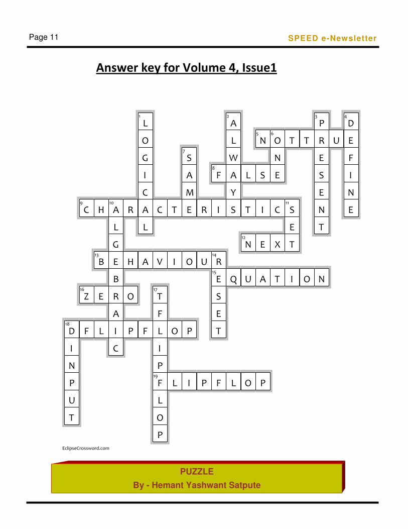
Answer key for Volume 4, Issue1
1 2 3 4
5 6
7
8
9 10 11
12
13 14
15
16 17
18
19
EclipseCrossword.com
D
I
N
P
U
T
C
Z
F
H
B
E
L
A
L
G
E
B
R
A
I
C
R
H
O
P
L
O
G
I
C
A
L
A
F
C
V
T
F
L
I
P
F
L
O
P
T
I
O
L
S
A
M
E
O
P
I
R
U
P
F
I
R
E
S
E
T
F
A
L
W
A
Y
S
Q
L
L
T
N
U
O
N
S
I
E
A
P
O
N
E
C
X
T
T
S
E
T
I
T
O
P
R
E
S
E
N
T
N
U
D
E
F
I
N
E
SPEED e-Newsletter
PUZZLE
By - Hemant Yashwant Satpute
Page 11