Route, Modulation Format, MIMO and Spectrum Assignment in ...

Outline Introduction & Motivation MIMO-MC Radars Radar and Comm. Spectrum Sharing Conclusions & Future Work
Spectrum Sharing Between MIMO-MC Radars andCommunication Systems
Bo Li ands Athina Petropulus
ECE Department, Rutgers, The State University of New JerseyWork supported by NSF under Grant ECCS-1408437 and Raytheon.
AsilomarNovember 07, 2016
Li & Petropulu (Rutgers University) Spectrum Sharing Between MIMO-MC Radars and Communication Systems 1 / 24

Outline Introduction & Motivation MIMO-MC Radars Radar and Comm. Spectrum Sharing Conclusions & Future Work
Outline
1 Introduction and Motivations
2 MIMO Radars with Matrix Completion
3 Spectrum Sharing Between MIMO-MC Radars and a MIMO Communication System
4 Conclusions & Future Work
Li & Petropulu (Rutgers University) Spectrum Sharing Between MIMO-MC Radars and Communication Systems 2 / 24

Outline
1 Introduction and Motivations
2 MIMO Radars with Matrix Completion
3 Spectrum Sharing Between MIMO-MC Radars and a MIMO Communication System
4 Conclusions & Future Work

Outline Introduction & Motivation MIMO-MC Radars Radar and Comm. Spectrum Sharing Conclusions & Future Work
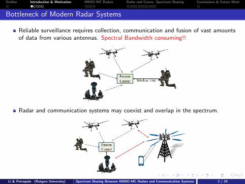
Bottleneck of Modern Radar Systems
Reliable surveillance requires collection, communication and fusion of vast amountsof data from various antennas. Spectral Bandwidth consuming!!
Radar and communication systems may coexist and overlap in the spectrum.
Li & Petropulu (Rutgers University) Spectrum Sharing Between MIMO-MC Radars and Communication Systems 3 / 24
Outline Introduction & Motivation MIMO-MC Radars Radar and Comm. Spectrum Sharing Conclusions & Future Work
Bottleneck of Modern Radar Systems
Reliable surveillance requires collection, communication and fusion of vast amountsof data from various antennas. Spectral Bandwidth consuming!!
Radar and communication systems may coexist and overlap in the spectrum.
Li & Petropulu (Rutgers University) Spectrum Sharing Between MIMO-MC Radars and Communication Systems 3 / 24

Outline Introduction & Motivation MIMO-MC Radars Radar and Comm. Spectrum Sharing Conclusions & Future Work
The Spectrum Crunch
The widespread adoption of smartphones, laptops, and tablets has dramaticallyincreased the need for more spectrum.
Figure 1: Global mobile traffic per month(src: Cisco, 2013)
Li & Petropulu (Rutgers University) Spectrum Sharing Between MIMO-MC Radars and Communication Systems 4 / 24

Outline Introduction & Motivation MIMO-MC Radars Radar and Comm. Spectrum Sharing Conclusions & Future Work
Motivation of Radar and Comm. Spectrum Sharing
[Lackpour et al, 11], [DARPA SSPARC program, 12], [FCC & NTIA reports, 12-15]
Radar and communications jointly consume most of the spectrum below 6 GHz.Spectrum held by commercial operators have heavy utilization in urban areas;Spectrum held by federal agencies have low average utilization.
Figure 2: Spectrum utilization (0-6 GHz) in downtown Berkeley(src: UC Berkeley, 2007)
FCC and NTIA have published the rule and order to share spectrum band 3550-3700MHz, previously held by federal agencies, with commercial wireless operators.
Li & Petropulu (Rutgers University) Spectrum Sharing Between MIMO-MC Radars and Communication Systems 5 / 24

Outline Introduction & Motivation MIMO-MC Radars Radar and Comm. Spectrum Sharing Conclusions & Future Work
Existing Approaches
Existing spectrum sharing approaches basically include three categories.
Avoiding interference by large spatial separation.
Figure 3: Shipborne radar exclusion zones (src: NTIA 15)
Dynamic spectrum access based on spectrum sensing.
Spatial multiplexing enabled by the multiple antennas at both the radar andcommunication systems
Radar waveforms were projected to the interference channel null space [Sodagari et al,12].Spatial filtering at the radar receiver was used to reduce the communicationinterference [Deng et al, 13].
Li & Petropulu (Rutgers University) Spectrum Sharing Between MIMO-MC Radars and Communication Systems 6 / 24

Outline Introduction & Motivation MIMO-MC Radars Radar and Comm. Spectrum Sharing Conclusions & Future Work
Existing Approaches
Existing spectrum sharing approaches basically include three categories.
Avoiding interference by large spatial separation.
Figure 3: Shipborne radar exclusion zones (src: NTIA 15)
Dynamic spectrum access based on spectrum sensing.Spatial multiplexing enabled by the multiple antennas at both the radar andcommunication systems
Radar waveforms were projected to the interference channel null space [Sodagari et al,12].Spatial filtering at the radar receiver was used to reduce the communicationinterference [Deng et al, 13].
Li & Petropulu (Rutgers University) Spectrum Sharing Between MIMO-MC Radars and Communication Systems 6 / 24
Outline Introduction & Motivation MIMO-MC Radars Radar and Comm. Spectrum Sharing Conclusions & Future Work
Joint Transmit Designs for Co-existence of MIMO WirelessCommunications and Sparse Sensing Radars in Clutter
Limitations on Existing Spatial Multiplexing Approach
Prior work only addressed the interference in one direction and ignored the other.
Clutter-free environments were assumed.
Our Contributions
We propose cooperative spectrum sharing approaches which address the mutualinterference simultaneously.
The proposed spectrum sharing framework can handle strong clutter.
The proposed spectrum sharing framework support MIMO radars with matrixcompletion. We further show that MC can even benefit spectrum sharing.
Li & Petropulu (Rutgers University) Spectrum Sharing Between MIMO-MC Radars and Communication Systems 7 / 24

Outline
1 Introduction and Motivations
2 MIMO Radars with Matrix Completion
3 Spectrum Sharing Between MIMO-MC Radars and a MIMO Communication System
4 Conclusions & Future Work

Outline Introduction & Motivation MIMO-MC Radars Radar and Comm. Spectrum Sharing Conclusions & Future Work
MIMO Radar Systems
Multiple-Input-Multiple-Output (MIMO) Radars:
MIMO radar system is a novel radar system of multiple antennas.
Each transmit antenna radiates an independent waveform.
Each receive antenna can apply a matched filter bank to extract the targetinformation.
… …
TX antennas RX antennas
Target
Fusion
Center
MIMO Radars gain superiority over traditional radars
High spatial resolution. MtMr spatial degrees of freedom can be achieved with Mt
TX and Mr RX antennas.
Omnidirectional illumination.Li & Petropulu (Rutgers University) Spectrum Sharing Between MIMO-MC Radars and Communication Systems 8 / 24

Outline Introduction & Motivation MIMO-MC Radars Radar and Comm. Spectrum Sharing Conclusions & Future Work
Matrix Completion
What is Matrix Completion?
“The task of filling in the missing entries of a partially observed matrix.”
For a low-rank matrix M, matrix completion can be done by solving relaxed nuclear nor-m optimization problem [Candes & Recht, 2009], [Candes & Tao, 2010]
min ‖X‖∗s.t. Xij = Mij , (i , j) ∈ Ω
(1)
where Ω denotes the set of observed entries.M can be perfectly recovered with high probability, given that
M is incoherent,
The observed entries are sampled uniformly at random and its size is large enough.
It is also shown that matrix completion is stable under noisy observations [Candes & Plan, 2010].
Li & Petropulu (Rutgers University) Spectrum Sharing Between MIMO-MC Radars and Communication Systems 9 / 24
Outline Introduction & Motivation MIMO-MC Radars Radar and Comm. Spectrum Sharing Conclusions & Future Work
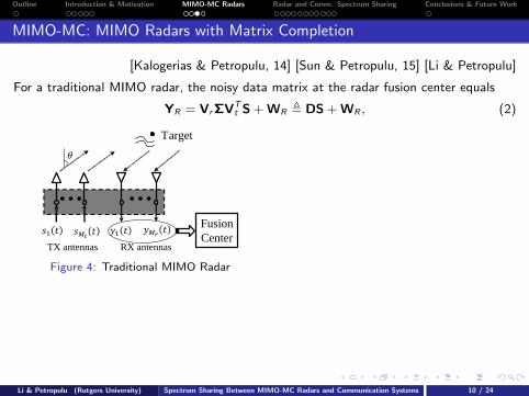
MIMO-MC: MIMO Radars with Matrix Completion
[Kalogerias & Petropulu, 14] [Sun & Petropulu, 15] [Li & Petropulu]
For a traditional MIMO radar, the noisy data matrix at the radar fusion center equals
YR = VrΣVTt S + WR , DS + WR , (2)
… …
TX antennas RX antennas
Target
Fusion
Center
Figure 4: Traditional MIMO Radar
Figure 5: MIMO-MC Radar
A new MIMO radar with matrix completion (MIMO-MC) was recently proposed basedon the fact that the data matrix DS ∈ CMr,R×L is low rank. Random sub-sampling isapplied to each receive antenna. Only the sub-sampled data are sent to the fusioncenter, where the full data matrix is recovered with high accuracy.
Save power and spectral bandwidth!
Li & Petropulu (Rutgers University) Spectrum Sharing Between MIMO-MC Radars and Communication Systems 10 / 24

Outline Introduction & Motivation MIMO-MC Radars Radar and Comm. Spectrum Sharing Conclusions & Future Work
MIMO-MC: MIMO Radars with Matrix Completion
[Kalogerias & Petropulu, 14] [Sun & Petropulu, 15] [Li & Petropulu]
For a traditional MIMO radar, the noisy data matrix at the radar fusion center equals
YR = VrΣVTt S + WR , DS + WR , (2)
… …
TX antennas RX antennas
Target
Fusion
Center
Figure 4: Traditional MIMO Radar Figure 5: MIMO-MC Radar
A new MIMO radar with matrix completion (MIMO-MC) was recently proposed basedon the fact that the data matrix DS ∈ CMr,R×L is low rank. Random sub-sampling isapplied to each receive antenna. Only the sub-sampled data are sent to the fusioncenter, where the full data matrix is recovered with high accuracy.
Save power and spectral bandwidth!
Li & Petropulu (Rutgers University) Spectrum Sharing Between MIMO-MC Radars and Communication Systems 10 / 24
Outline Introduction & Motivation MIMO-MC Radars Radar and Comm. Spectrum Sharing Conclusions & Future Work
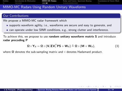
MIMO-MC Radars Using Random Unitary Waveforms
Our Contributions
We propose a MIMO-MC radar framework which
supports waveform agility, i.e., waveforms are secure and easy to generate, and
can operate under low SINR conditions, e.g., strong clutter and interference.
To achieve this, we propose to use random unitary waveform matrix S and introduceradar precoding P
Ω YR = Ω (VrΣVTt PS + WR) , Ω (M + WR), (3)
where Ω denotes the sub-sampling matrix and denotes Hadamard product.
Remarks
We show that the coherence of M is bounded by a small constant.
A random unitary matrix S can be easily obtained from any random Gaussianmatrix by performing the Gram-Schmidt orthogonalization.
The coherence of M is independent of P. This means that we can design P,without affecting the incoherence property of M, for the purpose of interferencesuppression.
Li & Petropulu (Rutgers University) Spectrum Sharing Between MIMO-MC Radars and Communication Systems 11 / 24

Outline Introduction & Motivation MIMO-MC Radars Radar and Comm. Spectrum Sharing Conclusions & Future Work
MIMO-MC Radars Using Random Unitary Waveforms
Our Contributions
We propose a MIMO-MC radar framework which
supports waveform agility, i.e., waveforms are secure and easy to generate, and
can operate under low SINR conditions, e.g., strong clutter and interference.
To achieve this, we propose to use random unitary waveform matrix S and introduceradar precoding P
Ω YR = Ω (VrΣVTt PS + WR) , Ω (M + WR), (3)
where Ω denotes the sub-sampling matrix and denotes Hadamard product.
Remarks
We show that the coherence of M is bounded by a small constant.
A random unitary matrix S can be easily obtained from any random Gaussianmatrix by performing the Gram-Schmidt orthogonalization.
The coherence of M is independent of P. This means that we can design P,without affecting the incoherence property of M, for the purpose of interferencesuppression.
Li & Petropulu (Rutgers University) Spectrum Sharing Between MIMO-MC Radars and Communication Systems 11 / 24
Outline
1 Introduction and Motivations
2 MIMO Radars with Matrix Completion
3 Spectrum Sharing Between MIMO-MC Radars and a MIMO Communication System
4 Conclusions & Future Work
Outline Introduction & Motivation MIMO-MC Radars Radar and Comm. Spectrum Sharing Conclusions & Future Work
The Coexistence Signal Model
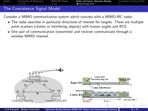
Consider a MIMO communication system which coexists with a MIMO-MC radar:
The radar searches in particular directions of interest for targets. There are multiplepoint scatters (clutter or interfering objects) with known angles and RCS.
One pair of communication transmitter and receiver communicate through awireless MIMO channel.
Assumptions:
Flat fading channel, narrow band radar and comm. signals;
Block fading: the channels remain constant for L symbols;
The two systems are time-synchronized and have the same symbol rate;
The two systems cooperate on channel estimation and feedback.
… …
… …
Collocated MIMO radar
Communication TX Communication RX
Li & Petropulu (Rutgers University) Spectrum Sharing Between MIMO-MC Radars and Communication Systems 12 / 24

Outline Introduction & Motivation MIMO-MC Radars Radar and Comm. Spectrum Sharing Conclusions & Future Work
The Coexistence Signal Model
The received signals at the MIMO-MC radar and communication RX are
Radar fusion center: Ω YR = Ω (DPS︸ ︷︷ ︸signal
+ CPS + G2XΛ2︸ ︷︷ ︸interference
+ WR︸︷︷︸noise
), (4a)
Communication receiver: YC = HX︸︷︷︸signal
+ G1PSΛ1︸ ︷︷ ︸interference
+ WC︸︷︷︸noise
, (4b)
whereC ,
∑Kck=1 β
ckvr (θck )vTt (θck ) is the clutter response matrix.
X , [x(1), . . . , x(L)]: the code-book of the communication system. We consider thecircularly symmetric complex Gaussian codewords x(l) ∼ CN (0,Rxl ).H ∈ CMr,C×Mt,C : the communication channel;G1 ∈ CMr,C×Mt,R : the interference channel radar → communication RX antennas;G2 ∈ CMr,R×Mt,C : the interference channel communication TX antennas → radar.Λ1 and Λ2 are diagonal matrices with entries e jαil , denoting the random phase offsetbetween the MIMO-MC radar and the communication system. α1lLl=1 are
distributed as N (0, σ2α), where σ2
α is small [Razavi, 96].WC and WR denote the additive noise.
Channels H, G1 and G2 are estimated and feedback to the radar andcommunication transmitter.
Li & Petropulu (Rutgers University) Spectrum Sharing Between MIMO-MC Radars and Communication Systems 13 / 24
Outline Introduction & Motivation MIMO-MC Radars Radar and Comm. Spectrum Sharing Conclusions & Future Work
Design Overview
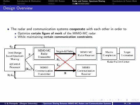
The radar and communication systems cooperate with each other in order toOptimize certain figure of merit of the MIMO-MC radarWhile maintaining certain communication constraints.
Li & Petropulu (Rutgers University) Spectrum Sharing Between MIMO-MC Radars and Communication Systems 14 / 24

Outline Introduction & Motivation MIMO-MC Radars Radar and Comm. Spectrum Sharing Conclusions & Future Work
The Mutual Interference
At the communication receiver, the interference plus noise covariance is given as
RCin = EG1PslsHl PHGH
1 + σ2C I , G1ΦGH
1 + σ2C I.
(According to [Jiang, 06], the entries of S can be approximated by distributionCN (0, 1/L). Φ , PPH/L is positive semidefinite.)
MIMO-MC radar sub-sampling actuallymodulates the interference channel G2.
The effective channel during the l-th symbolduration is G2l , ∆lG2 with ∆l = diag(Ω·l).
The interference channel is time-varying!Dynamic/adaptive communication transmissionis optimal, i.e., distinct Rxl for i = 1, . . . , L.
The effective interference power fromcommunication transmitter to MIMO-MC radar:
L∑l=1
Tr(
G2lRxlGH2l
)The interference depends on both Rxl and Ω.
Li & Petropulu (Rutgers University) Spectrum Sharing Between MIMO-MC Radars and Communication Systems 15 / 24

Outline Introduction & Motivation MIMO-MC Radars Radar and Comm. Spectrum Sharing Conclusions & Future Work
The Mutual Interference
At the communication receiver, the interference plus noise covariance is given as
RCin = EG1PslsHl PHGH
1 + σ2C I , G1ΦGH
1 + σ2C I.
(According to [Jiang, 06], the entries of S can be approximated by distributionCN (0, 1/L). Φ , PPH/L is positive semidefinite.)
MIMO-MC radar sub-sampling actuallymodulates the interference channel G2.
The effective channel during the l-th symbolduration is G2l , ∆lG2 with ∆l = diag(Ω·l).
The interference channel is time-varying!Dynamic/adaptive communication transmissionis optimal, i.e., distinct Rxl for i = 1, . . . , L.
The effective interference power fromcommunication transmitter to MIMO-MC radar:
L∑l=1
Tr(
G2lRxlGH2l
)
The interference depends on both Rxl and Ω.
Li & Petropulu (Rutgers University) Spectrum Sharing Between MIMO-MC Radars and Communication Systems 15 / 24

Outline Introduction & Motivation MIMO-MC Radars Radar and Comm. Spectrum Sharing Conclusions & Future Work
The Mutual Interference
At the communication receiver, the interference plus noise covariance is given as
RCin = EG1PslsHl PHGH
1 + σ2C I , G1ΦGH
1 + σ2C I.
(According to [Jiang, 06], the entries of S can be approximated by distributionCN (0, 1/L). Φ , PPH/L is positive semidefinite.)
MIMO-MC radar sub-sampling actuallymodulates the interference channel G2.
The effective channel during the l-th symbolduration is G2l , ∆lG2 with ∆l = diag(Ω·l).
The interference channel is time-varying!Dynamic/adaptive communication transmissionis optimal, i.e., distinct Rxl for i = 1, . . . , L.
The effective interference power fromcommunication transmitter to MIMO-MC radar:
L∑l=1
Tr(
G2lRxlGH2l
)The interference depends on both Rxl and Ω.
Li & Petropulu (Rutgers University) Spectrum Sharing Between MIMO-MC Radars and Communication Systems 15 / 24

Outline Introduction & Motivation MIMO-MC Radars Radar and Comm. Spectrum Sharing Conclusions & Future Work
The Design Variables and Constraints
Design Variables
The radar transmit precoder P, in terms of Φ;
The communication transmit covariance matrices Rxl for i = 1, . . . , L;
The MIMO-MC radar sub-sampling scheme Ω(Original result [Candes, et al, 10]) Ω corresponds to sampling uniformly at random.(Recent result [Srinadh, et al, 14]) Ω is required to have a large spectral gap.The spectral gap of Ω remains unaltered under row and column permutations but theinterference changes.
Design Constraints
The power budget at the communication transmitter:∑L
l=1 Tr(Rxl) ≤ Pt ,
The requirement on the average communication rate achieved during the L symbolperiods
Cavg(Rxl) ,1
L
∑L
l=1log2
∣∣∣I + R−1CinHRxlH
H∣∣∣ ≥ C (5)
Li & Petropulu (Rutgers University) Spectrum Sharing Between MIMO-MC Radars and Communication Systems 16 / 24

Outline Introduction & Motivation MIMO-MC Radars Radar and Comm. Spectrum Sharing Conclusions & Future Work
The Design Objective
The signal-to-interference-plus-noise ratio (SINR) is a widely used radarperformance metric.
MIMO-MC radar not only sub-samples the communication interference but also theechoes from targets and clutter.
Only the sampled target signal and sampled interference determine the matrixcompletion performance.
Based on this observation, we define the radar effective SINR (ESINR) as follows
ESINR ≡ effective signal power
effective interf. plus noise power
=mTr (ΦDt)
mTr (ΦCt) +∑L
l=1 Tr(G2lRxlGH
2l
)+ mσ2
R
.(6)
m is the number of entries sampled by the MIMO-MC receiver;
Dt =∑K
k=1 σ2β0
v∗t (θk )vTt (θk ), Ct =∑Kc
k=1 σ2βckv∗t (θck )vTt (θck );
σ2β0
, σ2βck
, and σ2R denote the variances of target, clutter and noise.
Li & Petropulu (Rutgers University) Spectrum Sharing Between MIMO-MC Radars and Communication Systems 17 / 24

Outline Introduction & Motivation MIMO-MC Radars Radar and Comm. Spectrum Sharing Conclusions & Future Work
Put Everything Together: Cooperative Spectrum Sharing
Cooperation & Knowledge Shared
Cooperate on estimation of G1, G2.Share H, G1, and G2 with the central processor.Jointly design of Φ, Ω and Rxl.
The cooperative approach for spectrum sharing problem can be formulated as
(P1) maxRxl0,Φ0,Ω
ESINR (Rx,Ω,Φ) ,
s.t. Cavg(Rxl,Φ) ≥ C , (7a)
L∑l=1
Tr (Rxl) ≤ PC , LTr (Φ) ≤ PR , (7b)
Tr (ΦVk) ≥ ξTr(Φ), ∀k ∈ N+K , ξ > 1 (7c)
Ω is Boolean and has large spectral gap (7d)
Problem (P1) is non-convex w.r.t. optimization variable triple (Rx,Ω,Φ).A local solution can be found by using alternating optimization in a loop.
Solving Rnxl with fixed Φn−1 and Ωn−1
Solving Φn with fixed Rnxl and Ωn−1
Solving Ωn with fixed Rnxl and Φn
Li & Petropulu (Rutgers University) Spectrum Sharing Between MIMO-MC Radars and Communication Systems 18 / 24

Outline Introduction & Motivation MIMO-MC Radars Radar and Comm. Spectrum Sharing Conclusions & Future Work
Simplifications and Comparisons
Constant-Rate Communication Transmission
A sub-optimal transmission approach of constant rate, i.e., Rxl ≡ Rx , ∀l ∈ N+L , has a lower
implementation complexity.
(P′1) maxRx0,Φ0
ESINR′ ,Tr (ΦDt)
Tr (ΦCt) + Tr(∑
∆lG2RxGH2
)/m + σ2
R
,
s.t. C(Rx ,Φ) ≥ C ,
LTr (Rx ) ≤ PC , LTr (Φ) ≤ PR ,
Tr (ΦVk ) ≥ 0, ∀k ∈ N+K ,
Pros: Only one matrix variable ⇒ lower complexity
Cons: Cannot adapt to the variation of the effective interference channel Rxl ⇒performance degradation
Traditional MIMO Radar: a special case when Ω = 1
Cons: There is no more modulation of the interference channel G2 due to sub-sampling.Smaller interference channel null space for multiplexing ⇒ performance degradation
Pros: Constant-rate communication transmission is sufficient ⇒ lower complexity
Li & Petropulu (Rutgers University) Spectrum Sharing Between MIMO-MC Radars and Communication Systems 19 / 24
Outline Introduction & Motivation MIMO-MC Radars Radar and Comm. Spectrum Sharing Conclusions & Future Work
Numerical Results: Radar TX Beampattern and MUSIC Spectrum
Azimuth Angle-50 0 50
Rad
ar T
X B
eam
patte
rn (
dB)
-20
0
20
40
60Proposed Precoding SchemeUniform Precoding SchemeNull Space Projection Scheme
Azimuth Angle-80 -60 -40 -20 0 20 40 60 80
Spa
tial S
pect
rum
in d
B
-2
-1.8
-1.6
-1.4
-1.2
-1
-0.8
-0.6
-0.4
-0.2
0
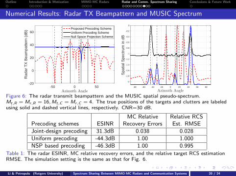
Figure 6: The radar transmit beampattern and the MUSIC spatial pseudo-spectrum.Mt,R = Mr,R = 16,Mt,C = Mr,C = 4. The true positions of the targets and clutters are labeledusing solid and dashed vertical lines, respectively. CNR=30 dB.
MC Relative Relative RCSPrecoding schemes ESINR Recovery Errors Est. RMSEJoint-design precoding 31.3dB 0.038 0.028Uniform precoding -44.3dB 1.00 1.000NSP based precoding -46.3dB 1.00 0.995
Table 1: The radar ESINR, MC relative recovery errors, and the relative target RCS estimationRMSE. The simulation setting is the same as that for Fig. 6.
Li & Petropulu (Rutgers University) Spectrum Sharing Between MIMO-MC Radars and Communication Systems 20 / 24
Outline Introduction & Motivation MIMO-MC Radars Radar and Comm. Spectrum Sharing Conclusions & Future Work
Numerical Results: Constant-Rate vs Adaptive
The variance of interference channel G2
0.1 0.2 0.3 0.4 0.5
ES
INR
in d
B
16
18
20
22
24
26
28
30
Constant Rate Comm. TXAdaptive Rate Comm. TX
The variance of interference channel G2
0.1 0.2 0.3 0.4 0.5M
C R
elat
ive
Rec
over
y E
rror
0.15
0.2
0.25
0.3
Constant Rate Comm. TXAdaptive Rate Comm. TX
The variance of interference channel G2
0.1 0.2 0.3 0.4 0.5
Rel
ativ
e R
CS
Est
imat
ion
RM
SE
0.15
0.2
0.25
Constant Rate Comm. TXAdaptive Rate Comm. TX
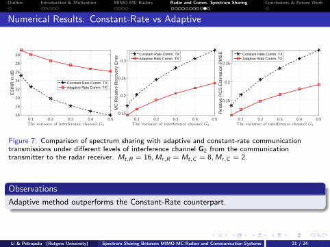
Figure 7: Comparison of spectrum sharing with adaptive and constant-rate communicationtransmissions under different levels of interference channel G2 from the communicationtransmitter to the radar receiver. Mt,R = 16,Mr,R = Mt,C = 8,Mr,C = 2.
Observations
Adaptive method outperforms the Constant-Rate counterpart.
Li & Petropulu (Rutgers University) Spectrum Sharing Between MIMO-MC Radars and Communication Systems 21 / 24

Outline Introduction & Motivation MIMO-MC Radars Radar and Comm. Spectrum Sharing Conclusions & Future Work
Numerical Results: MIMO-MC Radars and Traditional MIMO Radars
Radar Subsampling Rate p
0.2 0.3 0.4 0.5 0.6 0.7 0.8
ES
INR
in d
B
0
5
10
15
20Traditional MIMO RadarMIMO-MC Radar (p varies)
Radar Subsampling Rate p
0.2 0.3 0.4 0.5 0.6 0.7 0.8
MC
Rel
ativ
e R
ecov
ery
Err
or
0
0.2
0.4
0.6
0.8
1
1.2
Traditional MIMO RadarMIMO-MC Radar (p varies)
Radar Subsampling Rate p
0.2 0.3 0.4 0.5 0.6 0.7 0.8
Rel
ativ
e R
CS
Est
imat
ion
RM
SE
0.1
0.2
0.3
0.4
0.5
0.6Traditional MIMO RadarMIMO-MC Radar (p varies)
Figure 8: Comparison of spectrum sharing with traditional MIMO radars and the MIMO-MCradars with different subsampling rates p. Mt,R = 16,Mr,R = Mt,C = 8,Mr,C = 2.
Observations
The MIMO-MC radar achieves better target RCS estimation accuracy than thetraditional radar if p is between 0.4 and 0.7.
p < 0.4: The number of entries sampled is too small;0.4 ≤ p ≤ 0.7: Best compromise achieved!p > 0.7: Small ESINRs for p > 0.7 introduce high distortion in MC.
MIMO-MC radars can co-exist with comm. systems and achieve better target RCSestimation while saving up to 60% data samples.
Li & Petropulu (Rutgers University) Spectrum Sharing Between MIMO-MC Radars and Communication Systems 22 / 24

Outline
1 Introduction and Motivations
2 MIMO Radars with Matrix Completion
3 Spectrum Sharing Between MIMO-MC Radars and a MIMO Communication System
4 Conclusions & Future Work

Outline Introduction & Motivation MIMO-MC Radars Radar and Comm. Spectrum Sharing Conclusions & Future Work
Conclusions & Future Work
We have proposed:
A new MIMO-MC radar using random unitary waveform and supporting precodingWaveform agility and stable performance under strong interference are supported.
Cooperative spectrum sharing between a MIMO-MC radar and a MIMOcommunication system
Proposed spectrum sharing methods based on the joint design of the radar transmitprecoder, the radar sub-sampling scheme, and the communication transmit covariancematrix;Provided efficient algorithms and extensive comparisons;Higher level cooperation means better performance, at the cost of complexity.
MIMO radars and wireless MIMO communication coexistence is a new line of work withmany interesting challenges. We propose to work on the following directions:
Different design objective for radar and communication co-existence. Other designlogistics would be more favorable depending on the priority. Muti-objective design isalso an interesting topic.
Spectrum sharing between MIMO radars and multiple MIMO communicationsystems. It would be very interesting to extend current work to the scenario underwhich MIMO radars coexist with multiple pairs of MIMO transmitters and receivers.Distributed implementation for the centralized spectrum sharing algorithm in suchcase is also an important topic.
Li & Petropulu (Rutgers University) Spectrum Sharing Between MIMO-MC Radars and Communication Systems 23 / 24

Outline Introduction & Motivation MIMO-MC Radars Radar and Comm. Spectrum Sharing Conclusions & Future Work
Thank You
Thank You!Questions please
Li & Petropulu (Rutgers University) Spectrum Sharing Between MIMO-MC Radars and Communication Systems 23 / 24

Outline Introduction & Motivation MIMO-MC Radars Radar and Comm. Spectrum Sharing Conclusions & Future Work
Future Work
MIMO radars and wireless MIMO communication coexistence is a new line of work withmany interesting challenges. We propose to work on the following directions:
Different design objective for radar and communication co-existence. Other designlogistics would be more favorable depending on the priority. Muti-objective design isalso an interesting topic.
Spectrum sharing between MIMO radars and multiple MIMO communicationsystems. It would be very interesting to extend current work to the scenario underwhich MIMO radars coexist with multiple pairs of MIMO transmitters and receivers.Distributed implementation for the centralized spectrum sharing algorithm in suchcase is also an important topic.
The investigation of the coexistence of MIMO-OFDM radars and MIMO-OFDMcommunication systems. It is possible to formulate an optimization problem whichoptimally allocates the radar and communication resources to multiple antennas andmultiple sub-carriers simultaneously.
Li & Petropulu (Rutgers University) Spectrum Sharing Between MIMO-MC Radars and Communication Systems 23 / 24

Outline Introduction & Motivation MIMO-MC Radars Radar and Comm. Spectrum Sharing Conclusions & Future Work
Matrix Incoherence and Performance Guarantee
Subspace Coherence [Candes & Recht, 2009]
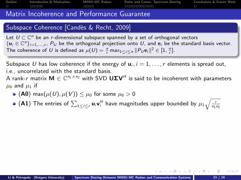
Let U ⊂ Cn be an r -dimensional subspace spanned by a set of orthogonal vectorsui ∈ Cni=1,...,r , PU be the orthogonal projection onto U, and ei be the standard basis vector.
The coherence of U is defined as µ(U) = nr
max1≤i≤n ‖PUei‖2 ∈ [1, nr
].
Subspace U has low coherence if the energy of ui , i = 1, . . . , r elements is spread out,i.e., uncorrelated with the standard basis.
A rank-r matrix M ∈ Cn1×n2 with SVD UΣVH is said to be incoherent with parametersµ0 and µ1 if
(A0) max(µ(U), µ(V )) ≤ µ0 for some µ0 > 0
(A1) The entries of∑
1≤i≤r uivHi have magnitudes upper bounded by µ1
√r
n1n2
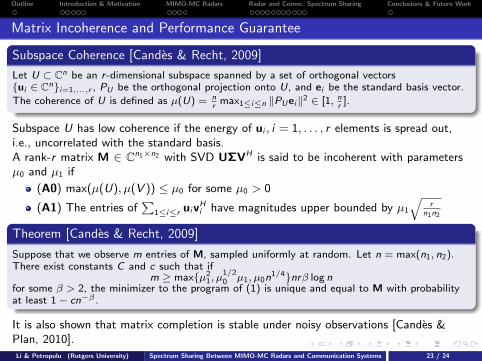
Theorem [Candes & Recht, 2009]
Suppose that we observe m entries of M, sampled uniformly at random. Let n = max(n1, n2).There exist constants C and c such that if
m ≥ maxµ21, µ
1/20 µ1, µ0n
1/4nrβ log nfor some β > 2, the minimizer to the program of (1) is unique and equal to M with probabilityat least 1− cn−β .
It is also shown that matrix completion is stable under noisy observations [Candes &Plan, 2010].
Li & Petropulu (Rutgers University) Spectrum Sharing Between MIMO-MC Radars and Communication Systems 23 / 24
Outline Introduction & Motivation MIMO-MC Radars Radar and Comm. Spectrum Sharing Conclusions & Future Work
Matrix Incoherence and Performance Guarantee
Subspace Coherence [Candes & Recht, 2009]
Let U ⊂ Cn be an r -dimensional subspace spanned by a set of orthogonal vectorsui ∈ Cni=1,...,r , PU be the orthogonal projection onto U, and ei be the standard basis vector.
The coherence of U is defined as µ(U) = nr
max1≤i≤n ‖PUei‖2 ∈ [1, nr
].
Subspace U has low coherence if the energy of ui , i = 1, . . . , r elements is spread out,i.e., uncorrelated with the standard basis.A rank-r matrix M ∈ Cn1×n2 with SVD UΣVH is said to be incoherent with parametersµ0 and µ1 if
(A0) max(µ(U), µ(V )) ≤ µ0 for some µ0 > 0
(A1) The entries of∑
1≤i≤r uivHi have magnitudes upper bounded by µ1
√r
n1n2
Theorem [Candes & Recht, 2009]
Suppose that we observe m entries of M, sampled uniformly at random. Let n = max(n1, n2).There exist constants C and c such that if
m ≥ maxµ21, µ
1/20 µ1, µ0n
1/4nrβ log nfor some β > 2, the minimizer to the program of (1) is unique and equal to M with probabilityat least 1− cn−β .
It is also shown that matrix completion is stable under noisy observations [Candes &Plan, 2010].
Li & Petropulu (Rutgers University) Spectrum Sharing Between MIMO-MC Radars and Communication Systems 23 / 24
Outline Introduction & Motivation MIMO-MC Radars Radar and Comm. Spectrum Sharing Conclusions & Future Work
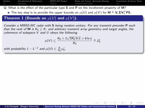
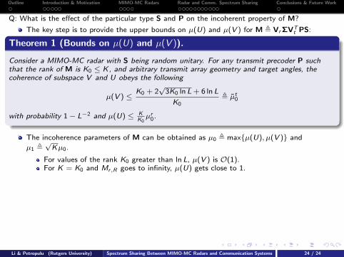
Q: What is the effect of the particular type S and P on the incoherent property of M?
The key step is to provide the upper bounds on µ(U) and µ(V ) for M , VrΣVTt PS:
Theorem 1 (Bounds on µ(U) and µ(V )).
Consider a MIMO-MC radar with S being random unitary. For any transmit precoder P suchthat the rank of M is K0 ≤ K, and arbitrary transmit array geometry and target angles, thecoherence of subspace V and U obeys the following
µ(V ) ≤K0 + 2
√3K0 ln L + 6 ln L
K0, µt0
with probability 1− L−2 and µ(U) ≤ KK0µr0.
The incoherence parameters of M can be obtained as µ0 , maxµ(U), µ(V ) and
µ1 ,√Kµ0.
For values of the rank K0 greater than ln L, µ(V ) is O(1).For K = K0 and Mr,R goes to infinity, µ(U) gets close to 1.
Remarks
A random unitary matrix S can be easily obtained from any random Gaussian matrix byperforming the Gram-Schmidt orthogonalization.
We show that the bound on the coherence parameters of M are independent of P. Thismeans that we can design P, without affecting the incoherence property of M, for thepurpose of interference suppression.
Li & Petropulu (Rutgers University) Spectrum Sharing Between MIMO-MC Radars and Communication Systems 24 / 24
Outline Introduction & Motivation MIMO-MC Radars Radar and Comm. Spectrum Sharing Conclusions & Future Work
Q: What is the effect of the particular type S and P on the incoherent property of M?
The key step is to provide the upper bounds on µ(U) and µ(V ) for M , VrΣVTt PS:
Theorem 1 (Bounds on µ(U) and µ(V )).
Consider a MIMO-MC radar with S being random unitary. For any transmit precoder P suchthat the rank of M is K0 ≤ K, and arbitrary transmit array geometry and target angles, thecoherence of subspace V and U obeys the following
µ(V ) ≤K0 + 2
√3K0 ln L + 6 ln L
K0, µt0
with probability 1− L−2 and µ(U) ≤ KK0µr0.
The incoherence parameters of M can be obtained as µ0 , maxµ(U), µ(V ) and
µ1 ,√Kµ0.
For values of the rank K0 greater than ln L, µ(V ) is O(1).For K = K0 and Mr,R goes to infinity, µ(U) gets close to 1.
Remarks
A random unitary matrix S can be easily obtained from any random Gaussian matrix byperforming the Gram-Schmidt orthogonalization.
We show that the bound on the coherence parameters of M are independent of P. Thismeans that we can design P, without affecting the incoherence property of M, for thepurpose of interference suppression.
Li & Petropulu (Rutgers University) Spectrum Sharing Between MIMO-MC Radars and Communication Systems 24 / 24

Outline Introduction & Motivation MIMO-MC Radars Radar and Comm. Spectrum Sharing Conclusions & Future Work
Alternating Iterations
The Alternating Iteration w.r.t. Rxlconvex; dual decomposition can be used to reduce the computation.
The Alternating Iteration w.r.t. ΩSolve Ω by searching the best permutation of an initial Ω0
minΩ
Tr(ΩT Q) s.t. Ω ∈ ℘(Ω0), (9)
We propose to reduce the search space as follows
minΩ
Tr(ΩT Q) s.t. Ω ∈ ℘r (Ω0), (10)
Proposition 2.
For any Ω0, searching for an Ω in ℘r (Ω0) can achieve the same EIP as ℘(Ω0).
Further, (10) can be formulated as a linear assignment problem and solved efficientlyin polynomial time O(M3
r,R) using the Hungarian algorithm.
The Alternating Iteration w.r.t. ΦThe sequential convex programming technique and Charnes-Cooper Transformationare applied to solve Φ.
Li & Petropulu (Rutgers University) Spectrum Sharing Between MIMO-MC Radars and Communication Systems 24 / 24

Outline Introduction & Motivation MIMO-MC Radars Radar and Comm. Spectrum Sharing Conclusions & Future Work
Discussions
Convergence of the Alternating Optimization
The objective ESINR is nondecreasing during the alternating iterations and is upper bounded. ⇒Convergence guaranteed according to the monotone convergence theorem [Yeh, et al, 06].
Feasibility
Proposition 3.
If C , ξ,PC > 0,PR > 0 are chosen such that C < Cmax(PC ) and ξ ≤ ξmax, then (P1) is feasible.
Cmax(PC ) and ξmax are given by
Cmax(PC ) , maxRxl0
1
L
L∑l=1
log2
∣∣∣I + σ−2C HRxlH
H∣∣∣ , s.t.
L∑l=1
Tr (Rxl ) ≤ PC
ξmax , maxΦ0,ξ≥0
ξ, s.t. Tr(ΦVk ) ≥ ξTr(Φ), ∀k ∈ N+K .
Rank of Φ
Proposition 4.
Any optimal solution of Φ has rank at most K. All rank-K solutions Φ∗K have the same rangespace. Any solution Φ∗
K− with rank less than K has range space such that R(Φ∗K− ) ⊂ R(Φ∗K ).
Li & Petropulu (Rutgers University) Spectrum Sharing Between MIMO-MC Radars and Communication Systems 24 / 24
Outline Introduction & Motivation MIMO-MC Radars Radar and Comm. Spectrum Sharing Conclusions & Future Work
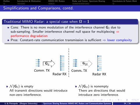
Simplifications and Comparisons, contd.
Traditional MIMO Radar: a special case when Ω = 1
Cons: There is no more modulation of the interference channel G2 due tosub-sampling. Smaller interference channel null space for multiplexing ⇒performance degradationPros: Constant-rate communication transmission is sufficient ⇒ lower complexity
N (G2) is emptyAll transmit directions would introducenon-zero interference.
N (G2l) is nonemptyThere are directions that wouldintroduce zero interference.
Li & Petropulu (Rutgers University) Spectrum Sharing Between MIMO-MC Radars and Communication Systems 24 / 24

Outline Introduction & Motivation MIMO-MC Radars Radar and Comm. Spectrum Sharing Conclusions & Future Work
Complexity Analysis
Performance vs Complexity (computation and cooperation)
Joint design Adaptive Rate Const. Rate Traditionalspectrum sharing (P1) (P′1) MIMO Radar
Variables Rxl,P,Ω Rx ,P Rx ,PComputation O(LM7
t,C + M7t,R + M3
r,R) O(M7t,C + M7
t,R) O(M7t,C + M7
t,R)
Table 2: Different joint design based methods proposed in the dissertation.
Trivial/None Null space projection Proposed
Precoder P ∝ I P ∝ VVH joint-designPerformance § § ©Computation Low Low HighCooperation Low level Medium level High level
Ignore each other Ignore comm. interf. ©No clutter mitigation No clutter mitigation ©
Table 3: Different radar precoding schemes.
Li & Petropulu (Rutgers University) Spectrum Sharing Between MIMO-MC Radars and Communication Systems 24 / 24

Outline Introduction & Motivation MIMO-MC Radars Radar and Comm. Spectrum Sharing Conclusions & Future Work
Numerical Results: Comparison of Different Levels of Cooperation
Radar TX Power Budget PR ×1051 2 3 4 5
ES
INR
in d
B
-10
0
10
20
30
Uniform Precoding + Selfish Comm.NSP Precoding + Selfish Comm.Uniform Precoding + Design R
xl&Ω
Design P + Selfish Comm.Proposed Joint Design
Radar TX Power Budget PR ×1051 2 3 4 5
MC
Rel
ativ
e R
ecov
ery
Err
or
0.2
0.4
0.6
0.8
1
Uniform Precoding + Selfish Comm.NSP Precoding + Selfish Comm.Uniform Precoding + Design R
xl&Ω
Design P + Selfish Comm.Proposed Joint Design
Radar TX Power Budget PR ×1051 2 3 4 5
Rel
ativ
e R
CS
Est
imat
ion
RM
SE
0.2
0.4
0.6
0.8
1
Uniform Precoding + Selfish Comm.NSP Precoding + Selfish Comm.Uniform Precoding + Design R
xl&Ω
Design P + Selfish Comm.Proposed Joint Design
Figure 9: Comparison of spectrum sharing with different levels of cooperation between theMIMO-MC radar and the communication system under different PR .Mt,R = Mr,R = 16,Mt,C = Mr,C = 4.
Observations
The propose joint design method significantly outperforms other non-cooperative andpartial cooperative methods.
Li & Petropulu (Rutgers University) Spectrum Sharing Between MIMO-MC Radars and Communication Systems 24 / 24