Spectrum Microwave Presentation - API Techmicro.apitech.com/pdf/tours/amptour.pdf · - RF/Microwave...
33
1 Spectrum Microwave Presentation
-
Upload
truongngoc -
Category
Documents
-
view
246 -
download
5
Transcript of Spectrum Microwave Presentation - API Techmicro.apitech.com/pdf/tours/amptour.pdf · - RF/Microwave...
1
Spectrum Microwave Presentation
2
The Spectrum Family of Businesses
Microwave Components & Systems Business | SpectrumMicrowave.com- Amplifiers, Mixers, Switches, Oscillators & Sources- RF/Microwave Filters, Diplexers & Multiplexers, Integrated Multifunction Modules- Thin Film Substrates, Hybrid Assembly Services
EMI Filter & Components Business | specemc.com- EMI Surge Suppression Components & Modules- Power Line Filters & Power Entry Modules- Interconnect Devices- Terminal Blocks & Passive Components
Power Management Systems | specpower.com- Power Management & Distribution Systems- AC & DC Power Strips- Power Monitoring Equipment: Environmental, Electrical, Security, Mechanical
Sensors & Controls Business | specsensors.com- Potentiometers, Temp Sensing Probes, Surge Current Limiters
3
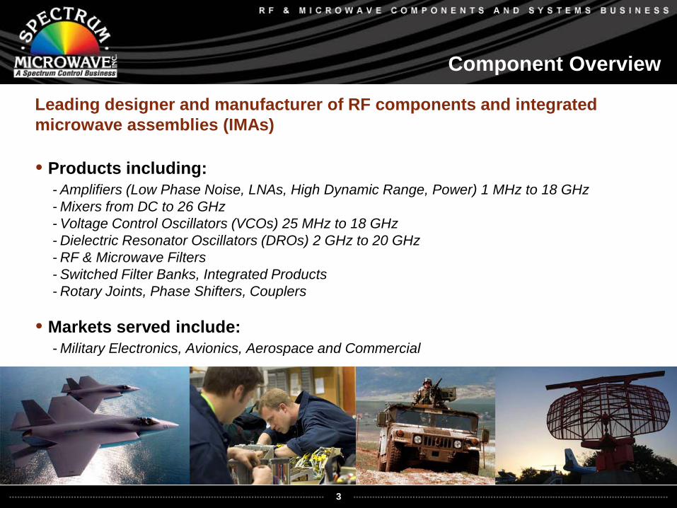
Component Overview
Leading designer and manufacturer of RF components and integrated microwave assemblies (IMAs)
• Products including:- Amplifiers (Low Phase Noise, LNAs, High Dynamic Range, Power) 1 MHz to 18 GHz- Mixers from DC to 26 GHz- Voltage Control Oscillators (VCOs) 25 MHz to 18 GHz- Dielectric Resonator Oscillators (DROs) 2 GHz to 20 GHz- RF & Microwave Filters- Switched Filter Banks, Integrated Products- Rotary Joints, Phase Shifters, Couplers
• Markets served include:- Military Electronics, Avionics, Aerospace and Commercial
4
2
3
145
6
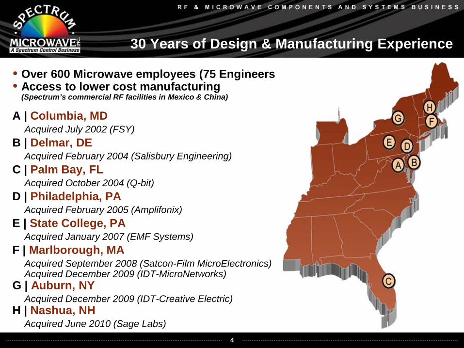
30 Years of Design & Manufacturing Experience
• Over 600 Microwave employees (75 Engineers)• Access to lower cost manufacturing
(Spectrum’s commercial RF facilities in Mexico & China)
A | Columbia, MDAcquired July 2002 (FSY)
B | Delmar, DEAcquired February 2004 (Salisbury Engineering)
C | Palm Bay, FLAcquired October 2004 (Q-bit)
D | Philadelphia, PAAcquired February 2005 (Amplifonix)
E | State College, PAAcquired January 2007 (EMF Systems)
F | Marlborough, MAAcquired September 2008 (Satcon-Film MicroElectronics)Acquired December 2009 (IDT-MicroNetworks)
G | Auburn, NYAcquired December 2009 (IDT-Creative Electric)
H | Nashua, NHAcquired June 2010 (Sage Labs)
7 8
5
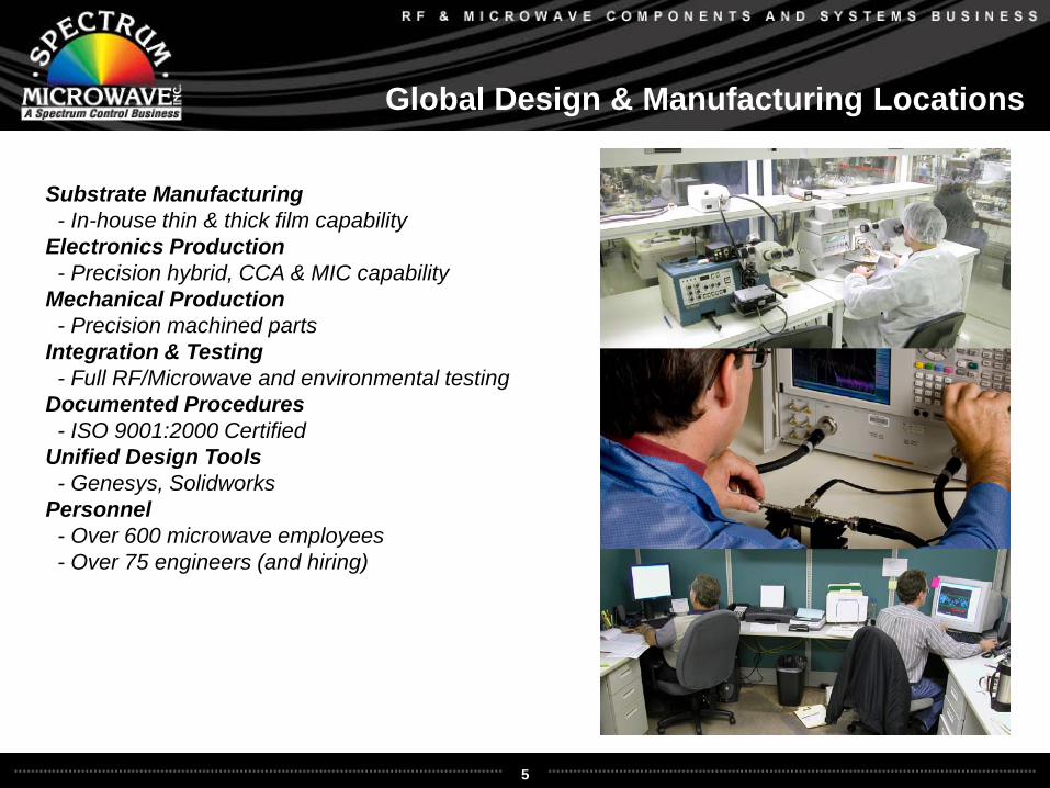
Global Design & Manufacturing Locations
Substrate Manufacturing- In-house thin & thick film capability
Electronics Production- Precision hybrid, CCA & MIC capability
Mechanical Production- Precision machined parts
Integration & Testing- Full RF/Microwave and environmental testing
Documented Procedures- ISO 9001:2000 Certified
Unified Design Tools- Genesys, Solidworks
Personnel- Over 600 microwave employees- Over 75 engineers (and hiring)
6
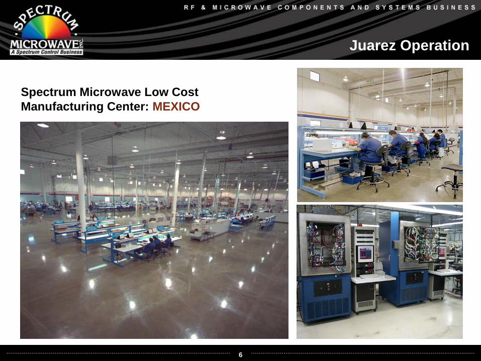
Juarez Operation
Spectrum Microwave Low CostManufacturing Center: MEXICO
7
Dongguan Operation
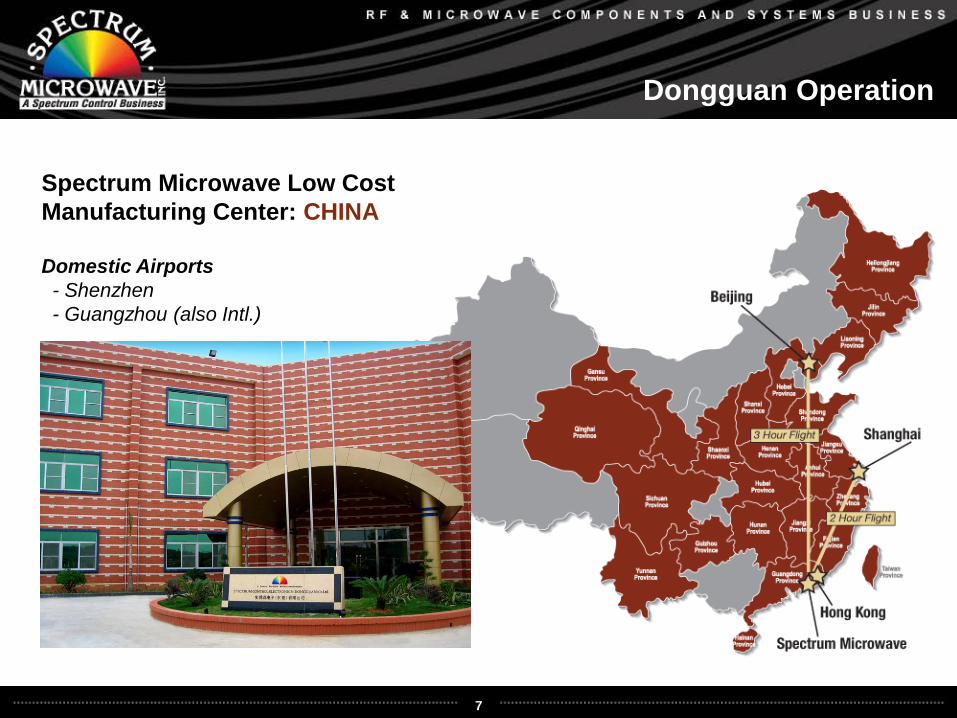
Spectrum Microwave Low CostManufacturing Center: CHINA
Domestic Airports- Shenzhen- Guangzhou (also Intl.)
8
Product Line Overview
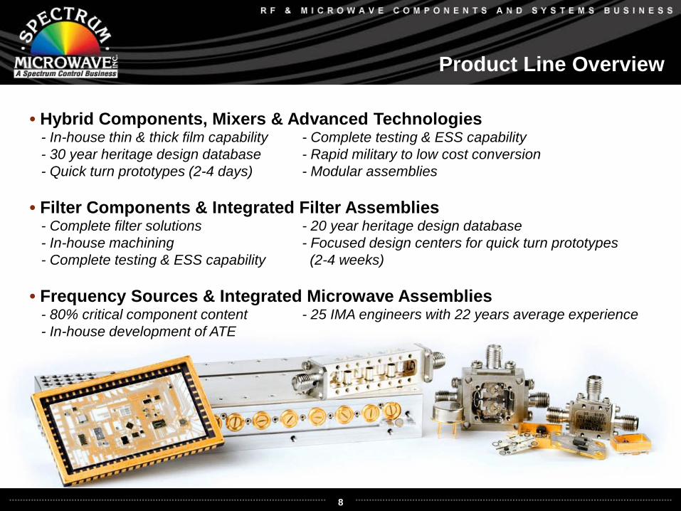
• Hybrid Components, Mixers & Advanced Technologies- In-house thin & thick film capability - Complete testing & ESS capability- 30 year heritage design database - Rapid military to low cost conversion- Quick turn prototypes (2-4 days) - Modular assemblies
• Filter Components & Integrated Filter Assemblies- Complete filter solutions - 20 year heritage design database- In-house machining - Focused design centers for quick turn prototypes - Complete testing & ESS capability (2-4 weeks)
• Frequency Sources & Integrated Microwave Assemblies- 80% critical component content - 25 IMA engineers with 22 years average experience- In-house development of ATE
9
Amplifiers | Packages-Hybrid
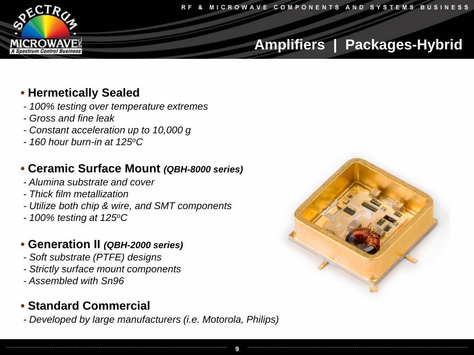
• Hermetically Sealed- 100% testing over temperature extremes- Gross and fine leak- Constant acceleration up to 10,000 g- 160 hour burn-in at 125oC
• Ceramic Surface Mount (QBH-8000 series)- Alumina substrate and cover- Thick film metallization- Utilize both chip & wire, and SMT components- 100% testing at 125oC
• Generation II (QBH-2000 series)- Soft substrate (PTFE) designs- Strictly surface mount components- Assembled with Sn96
• Standard Commercial- Developed by large manufacturers (i.e. Motorola, Philips)
10
Amplifiers | Performance
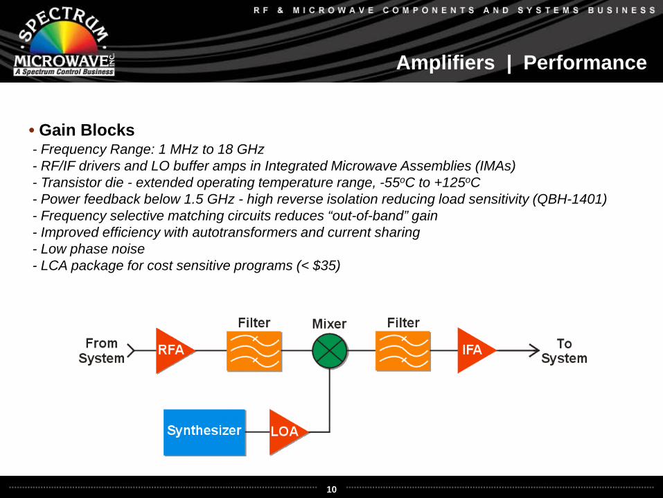
• Gain Blocks- Frequency Range: 1 MHz to 18 GHz- RF/IF drivers and LO buffer amps in Integrated Microwave Assemblies (IMAs)- Transistor die - extended operating temperature range, -55oC to +125oC- Power feedback below 1.5 GHz - high reverse isolation reducing load sensitivity (QBH-1401)- Frequency selective matching circuits reduces “out-of-band” gain- Improved efficiency with autotransformers and current sharing- Low phase noise- LCA package for cost sensitive programs (< $35)
11
Amplifiers | Hi-Reverse Isolation
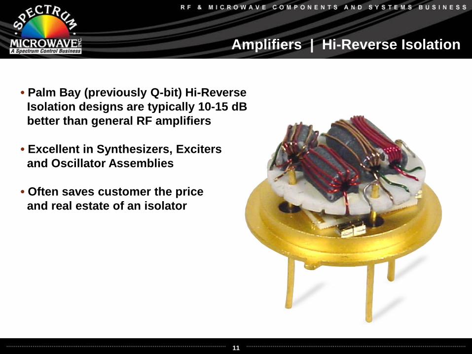
• Palm Bay (previously Q-bit) Hi-ReverseIsolation designs are typically 10-15 dBbetter than general RF amplifiers
• Excellent in Synthesizers, Exciters and Oscillator Assemblies
• Often saves customer the price and real estate of an isolator
12
Amplifiers | Low Noise Performance
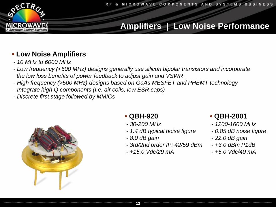
• Low Noise Amplifiers- 10 MHz to 6000 MHz- Low frequency (<500 MHz) designs generally use silicon bipolar transistors and incorporatethe low loss benefits of power feedback to adjust gain and VSWR
- High frequency (>500 MHz) designs based on GaAs MESFET and PHEMT technology- Integrate high Q components (I.e. air coils, low ESR caps)- Discrete first stage followed by MMICs
• QBH-920- 30-200 MHz- 1.4 dB typical noise figure- 8.0 dB gain- 3rd/2nd order IP: 42/59 dBm- +15.0 Vdc/29 mA
• QBH-2001- 1200-1600 MHz- 0.85 dB noise figure- 22.0 dB gain- +3.0 dBm P1dB- +5.0 Vdc/40 mA
13
Amplifiers | Broadband Performance
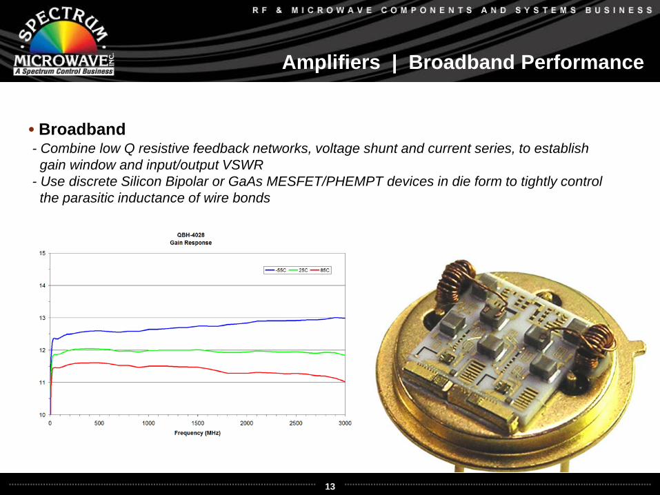
• Broadband- Combine low Q resistive feedback networks, voltage shunt and current series, to establishgain window and input/output VSWR
- Use discrete Silicon Bipolar or GaAs MESFET/PHEMPT devices in die form to tightly controlthe parasitic inductance of wire bonds
14
Amplifiers | Low Noise Amplifiers
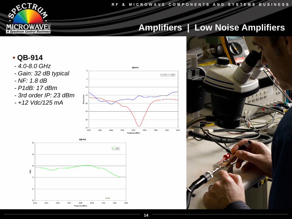
• QB-914- 4.0-8.0 GHz- Gain: 32 dB typical- NF: 1.8 dB- P1dB: 17 dBm- 3rd order IP: 23 dBm- +12 Vdc/125 mA
15
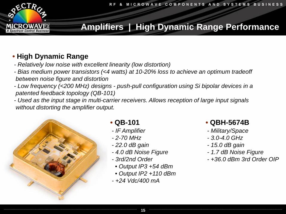
Amplifiers | High Dynamic Range Performance
• High Dynamic Range- Relatively low noise with excellent linearity (low distortion)- Bias medium power transistors (<4 watts) at 10-20% loss to achieve an optimum tradeoffbetween noise figure and distortion
- Low frequency (<200 MHz) designs - push-pull configuration using Si bipolar devices in apatented feedback topology (QB-101)
- Used as the input stage in multi-carrier receivers. Allows reception of large input signalswithout distorting the amplifier output.
• QB-101- IF Amplifier- 2-70 MHz- 22.0 dB gain- 4.0 dB Noise Figure- 3rd/2nd Order • Output IP3 +54 dBm• Output IP2 +110 dBm
- +24 Vdc/400 mA
• QBH-5674B- Military/Space- 3.0-4.0 GHz- 15.0 dB gain- 1.7 dB Noise Figure- +36.0 dBm 3rd Order OIP
16
Amplifiers | Architecture/Topologies
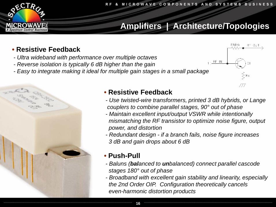
• Resistive Feedback- Ultra wideband with performance over multiple octaves- Reverse isolation is typically 6 dB higher than the gain- Easy to integrate making it ideal for multiple gain stages in a small package
• Resistive Feedback- Use twisted-wire transformers, printed 3 dB hybrids, or Lange couplers to combine parallel stages, 90° out of phase
- Maintain excellent input/output VSWR while intentionally mismatching the RF transistor to optimize noise figure, output power, and distortion
- Redundant design - if a branch fails, noise figure increases 3 dB and gain drops about 6 dB
• Push-Pull- Baluns (balanced to unbalanced) connect parallel cascode stages 180° out of phase
- Broadband with excellent gain stability and linearity, especially the 2nd Order OIP. Configuration theoretically cancels even-harmonic distortion products
17
Amplifiers | Ultra Low Phase Noise Performance
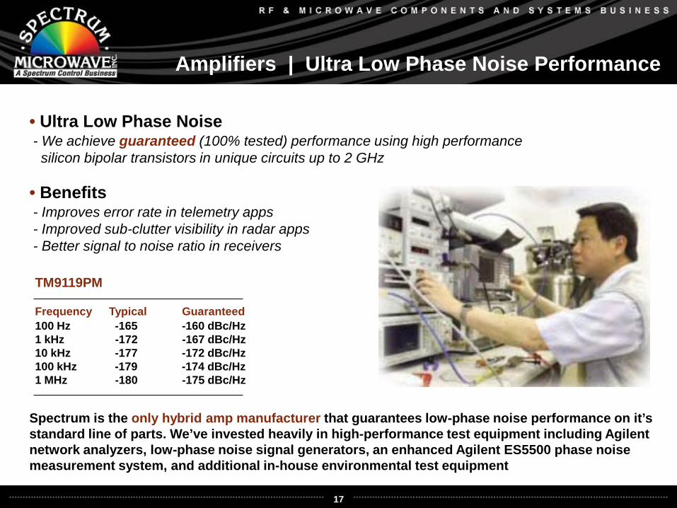
• Ultra Low Phase Noise- We achieve guaranteed (100% tested) performance using high performance silicon bipolar transistors in unique circuits up to 2 GHz
• Benefits- Improves error rate in telemetry apps- Improved sub-clutter visibility in radar apps- Better signal to noise ratio in receivers
Spectrum is the only hybrid amp manufacturer that guarantees low-phase noise performance on it’s standard line of parts. We’ve invested heavily in high-performance test equipment including Agilent network analyzers, low-phase noise signal generators, an enhanced Agilent ES5500 phase noise measurement system, and additional in-house environmental test equipment
Frequency Typical Guaranteed100 Hz -165 -160 dBc/Hz1 kHz -172 -167 dBc/Hz10 kHz -177 -172 dBc/Hz100 kHz -179 -174 dBc/Hz1 MHz -180 -175 dBc/Hz
TM9119PM
18
Amplifiers | Ultra Low Phase Noise Performance
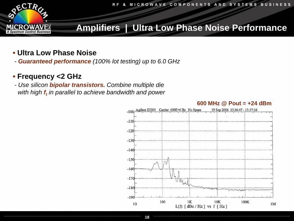
600 MHz @ Pout = +24 dBm
• Ultra Low Phase Noise- Guaranteed performance (100% lot testing) up to 6.0 GHz
• Frequency <2 GHz- Use silicon bipolar transistors. Combine multiple diewith high ft in parallel to achieve bandwidth and power
19
Amplifiers | Ceramic Lower Cost Amplifiers
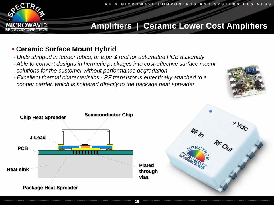
• Ceramic Surface Mount Hybrid- Units shipped in feeder tubes, or tape & reel for automated PCB assembly- Able to convert designs in hermetic packages into cost-effective surface mount solutions for the customer without performance degradation
- Excellent thermal characteristics - RF transistor is eutectically attached to acopper carrier, which is soldered directly to the package heat spreader
PCB
Heat sinkPlated throughvias
Chip Heat Spreader Semiconductor Chip
Package Heat Spreader
J-Lead
20
Amplifiers | Ceramic Lower Cost Amplifiers
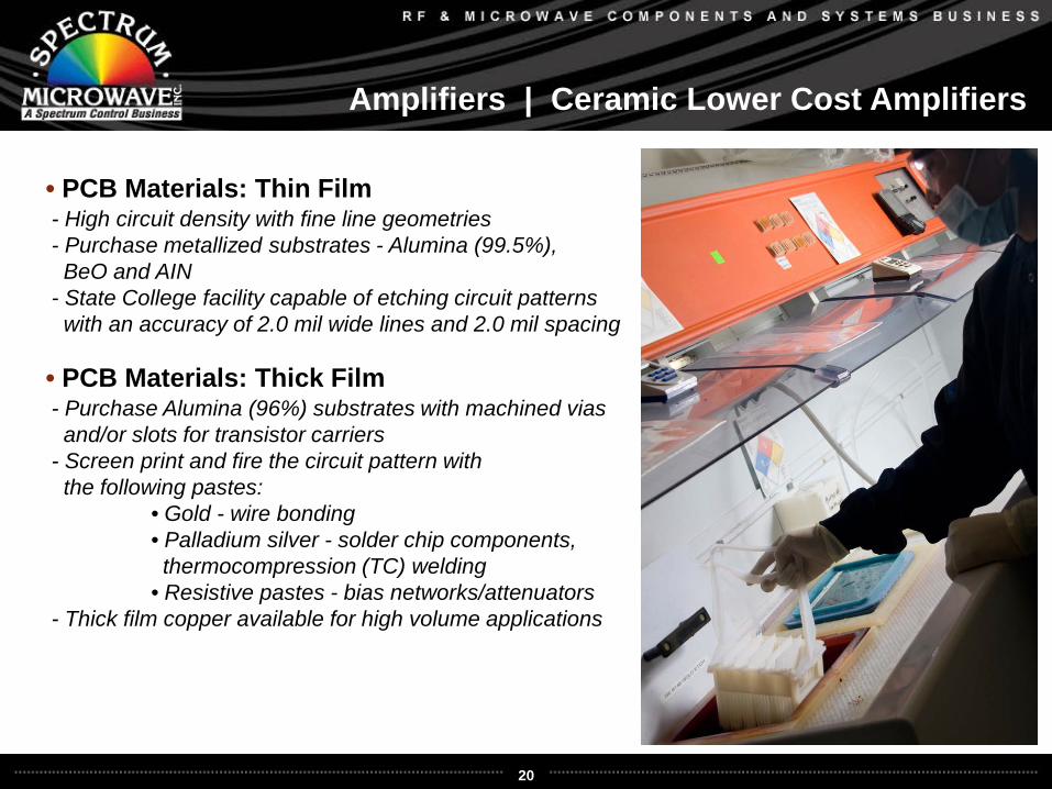
• PCB Materials: Thin Film- High circuit density with fine line geometries- Purchase metallized substrates - Alumina (99.5%),BeO and AIN
- State College facility capable of etching circuit patternswith an accuracy of 2.0 mil wide lines and 2.0 mil spacing
• PCB Materials: Thick Film- Purchase Alumina (96%) substrates with machined viasand/or slots for transistor carriers
- Screen print and fire the circuit pattern with the following pastes:
• Gold - wire bonding• Palladium silver - solder chip components,thermocompression (TC) welding
• Resistive pastes - bias networks/attenuators- Thick film copper available for high volume applications
21
Amplifiers | Generation II Package
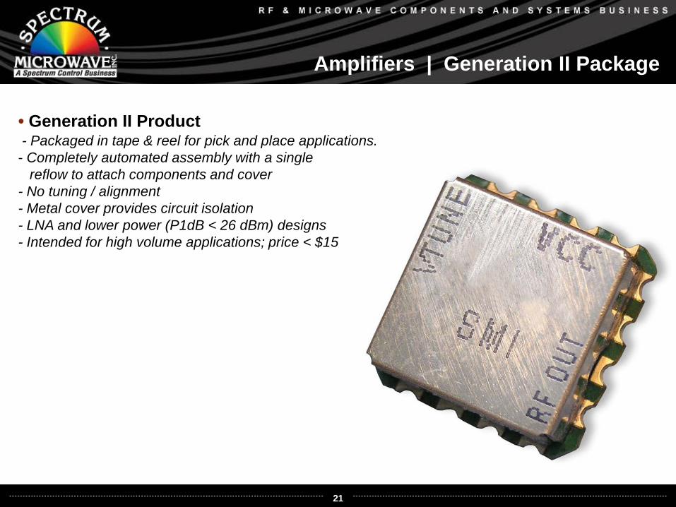
• Generation II Product- Packaged in tape & reel for pick and place applications.- Completely automated assembly with a single
reflow to attach components and cover - No tuning / alignment- Metal cover provides circuit isolation- LNA and lower power (P1dB < 26 dBm) designs- Intended for high volume applications; price < $15
22
Amplifiers | Ceramic Lower Cost Amplifiers
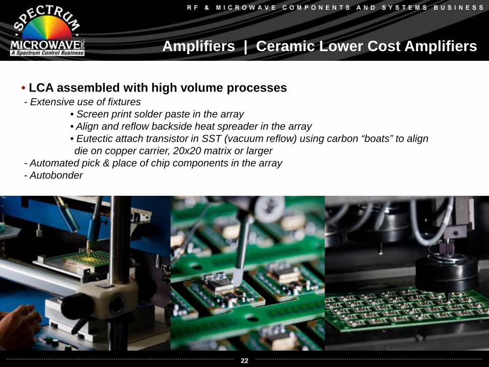
• LCA assembled with high volume processes- Extensive use of fixtures
• Screen print solder paste in the array• Align and reflow backside heat spreader in the array• Eutectic attach transistor in SST (vacuum reflow) using carbon “boats” to aligndie on copper carrier, 20x20 matrix or larger
- Automated pick & place of chip components in the array- Autobonder
23
Amplifiers | Ceramic Lower Cost Amplifiers
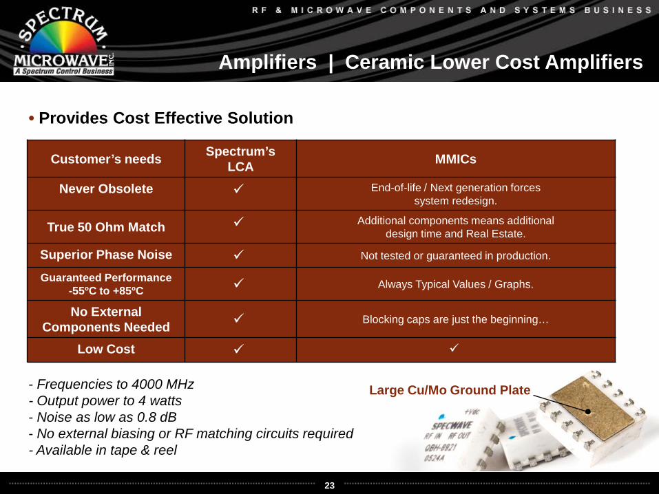
• Provides Cost Effective Solution
Customer’s needs Spectrum’s LCA MMICs
Never Obsolete End-of-life / Next generation forces system redesign.
True 50 Ohm Match Additional components means additional design time and Real Estate.
Superior Phase Noise Not tested or guaranteed in production.
Guaranteed Performance -55ºC to +85ºC Always Typical Values / Graphs.
No External Components Needed Blocking caps are just the beginning…
Low Cost
- Frequencies to 4000 MHz- Output power to 4 watts- Noise as low as 0.8 dB- No external biasing or RF matching circuits required- Available in tape & reel
Large Cu/Mo Ground Plate
24
Amplifiers | Broadband Power Amplifiers
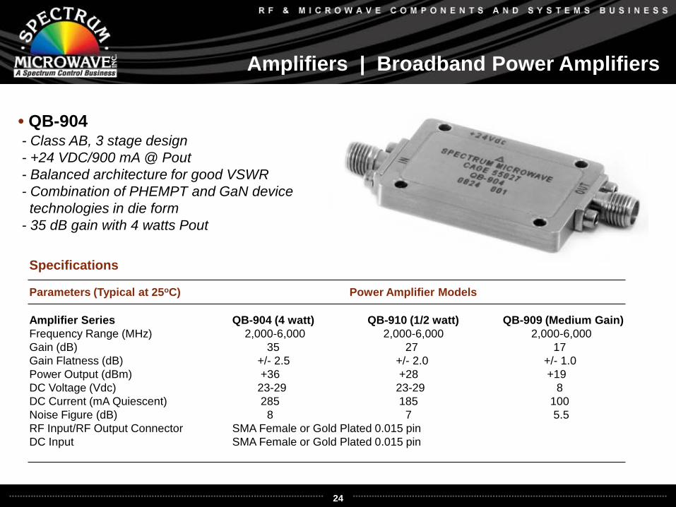
• QB-904- Class AB, 3 stage design- +24 VDC/900 mA @ Pout- Balanced architecture for good VSWR- Combination of PHEMPT and GaN device technologies in die form
- 35 dB gain with 4 watts Pout
Parameters (Typical at 25oC) Power Amplifier Models
Amplifier Series QB-904 (4 watt) QB-910 (1/2 watt) QB-909 (Medium Gain)Frequency Range (MHz) 2,000-6,000 2,000-6,000 2,000-6,000 Gain (dB) 35 27 17Gain Flatness (dB) +/- 2.5 +/- 2.0 +/- 1.0Power Output (dBm) +36 +28 +19DC Voltage (Vdc) 23-29 23-29 8DC Current (mA Quiescent) 285 185 100Noise Figure (dB) 8 7 5.5RF Input/RF Output Connector SMA Female or Gold Plated 0.015 pinDC Input SMA Female or Gold Plated 0.015 pin
Specifications
25
Amplifiers | Performance
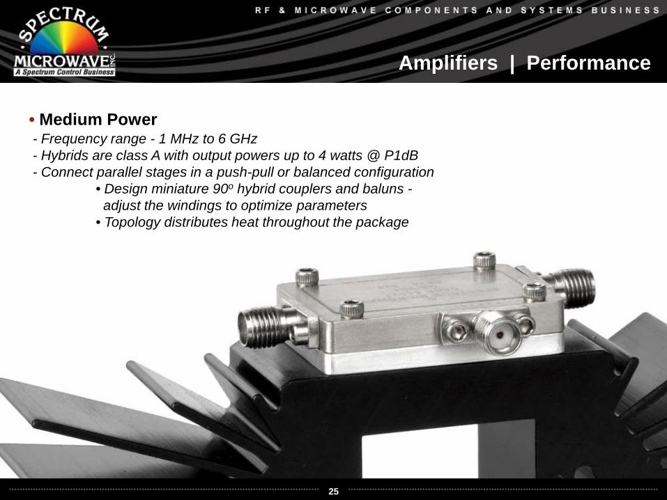
• Medium Power- Frequency range - 1 MHz to 6 GHz- Hybrids are class A with output powers up to 4 watts @ P1dB- Connect parallel stages in a push-pull or balanced configuration
• Design miniature 90o hybrid couplers and baluns -adjust the windings to optimize parameters
• Topology distributes heat throughout the package
26
Amplifiers | QB-904 Performance, 4 watts 2-6 GHz
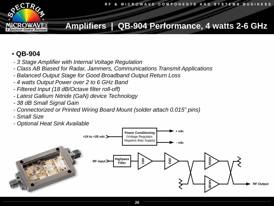
• QB-904- 3 Stage Amplifier with Internal Voltage Regulation- Class AB Biased for Radar, Jammers, Communications Transmit Applications- Balanced Output Stage for Good Broadband Output Return Loss- 4 watts Output Power over 2 to 6 GHz Band- Filtered Input (18 dB/Octave filter roll-off)- Latest Gallium Nitride (GaN) device Technology- 38 dB Small Signal Gain- Connectorized or Printed Wiring Board Mount (solder attach 0.015” pins)- Small Size - Optional Heat Sink Available
AR
1
AR
2
AR
3AA
R3B
RF input
RF Output
Power Conditioning(Voltage Regulator,
Negative Bias Supply)
+ vdc
- vdc
+24 to +28 vdc
HighpassFilter
27
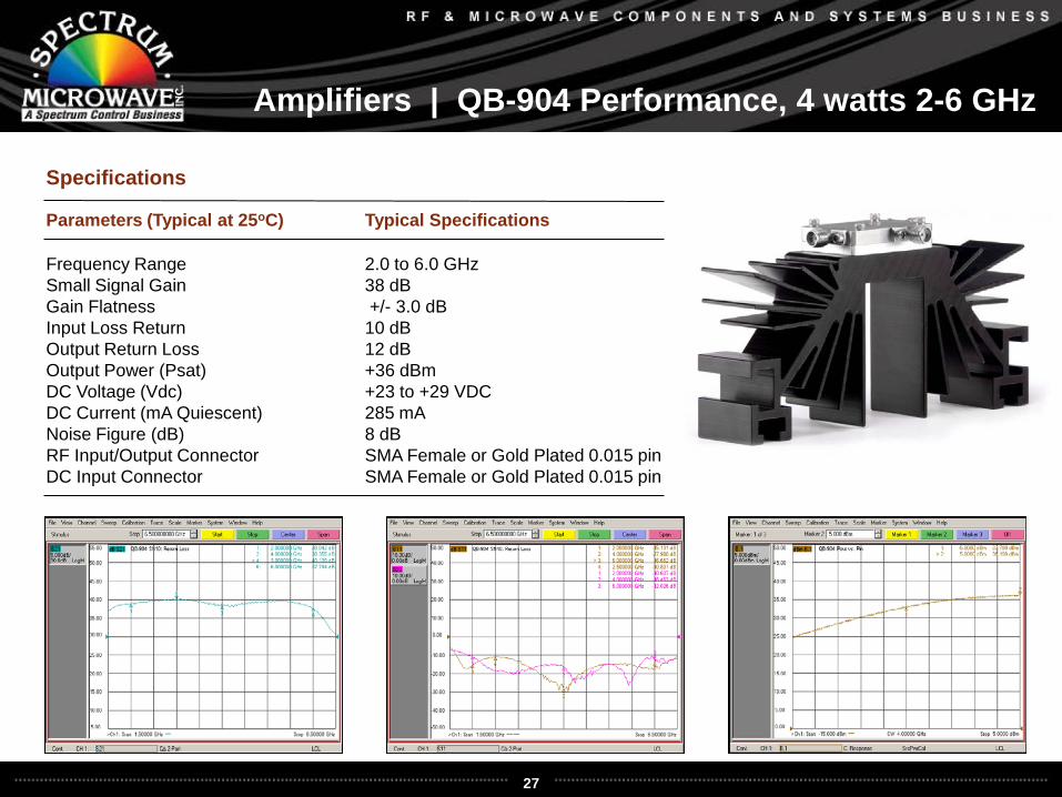
Amplifiers | QB-904 Performance, 4 watts 2-6 GHz
Parameters (Typical at 25oC) Typical Specifications
Frequency Range 2.0 to 6.0 GHz Small Signal Gain 38 dBGain Flatness +/- 3.0 dBInput Loss Return 10 dBOutput Return Loss 12 dBOutput Power (Psat) +36 dBmDC Voltage (Vdc) +23 to +29 VDCDC Current (mA Quiescent) 285 mANoise Figure (dB) 8 dBRF Input/Output Connector SMA Female or Gold Plated 0.015 pinDC Input Connector SMA Female or Gold Plated 0.015 pin
Specifications
28
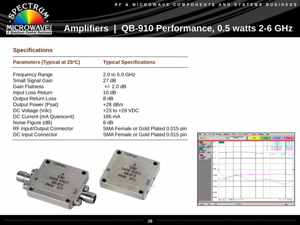
Amplifiers | QB-910 Performance, 0.5 watts 2-6 GHz
Parameters (Typical at 25oC) Typical Specifications
Frequency Range 2.0 to 6.0 GHz Small Signal Gain 27 dBGain Flatness +/- 2.0 dBInput Loss Return 10 dBOutput Return Loss 8 dBOutput Power (Psat) +28 dBmDC Voltage (Vdc) +23 to +29 VDCDC Current (mA Quiescent) 185 mANoise Figure (dB) 8 dBRF Input/Output Connector SMA Female or Gold Plated 0.015 pinDC Input Connector SMA Female or Gold Plated 0.015 pin
Specifications
29
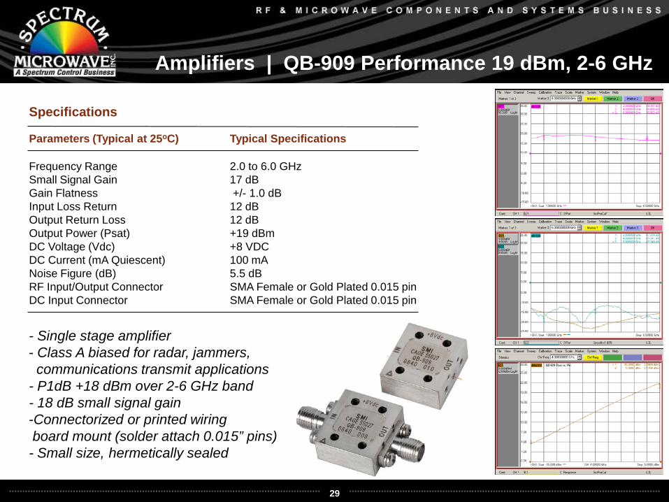
Amplifiers | QB-909 Performance 19 dBm, 2-6 GHz
Parameters (Typical at 25oC) Typical Specifications
Frequency Range 2.0 to 6.0 GHz Small Signal Gain 17 dBGain Flatness +/- 1.0 dBInput Loss Return 12 dBOutput Return Loss 12 dBOutput Power (Psat) +19 dBmDC Voltage (Vdc) +8 VDCDC Current (mA Quiescent) 100 mANoise Figure (dB) 5.5 dBRF Input/Output Connector SMA Female or Gold Plated 0.015 pinDC Input Connector SMA Female or Gold Plated 0.015 pin
Specifications
- Single stage amplifier- Class A biased for radar, jammers, communications transmit applications
- P1dB +18 dBm over 2-6 GHz band- 18 dB small signal gain-Connectorized or printed wiringboard mount (solder attach 0.015” pins)- Small size, hermetically sealed
30
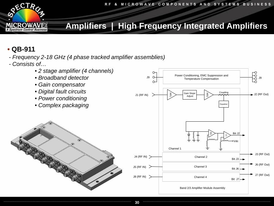
Amplifiers | High Frequency Integrated Amplifiers
• QB-911- Frequency 2-18 GHz (4 phase tracked amplifier assemblies)- Consists of…
• 2 stage amplifier (4 channels)• Broadband detector• Gain compensator• Digital fault circuits• Power conditioning• Complex packaging
Gain Slope Adjust
EqualizerAR
1
AR2
A1 C1
J2 (RF Out)J1 (RF IN)
Vdc
J3 (RF Out)
J6 (RF Out)
J7 (RF Out)
J4 (RF IN)
J5 (RF IN)
J8 (RF IN)
Bit J2
Bit J3
Bit J6
Bit J7
Channel 1
Channel 2
Channel 3
Channel 4
Power Conditioning, EMC Suppression andTemperature CompensationJ9
Coupling
Band 2/3 Amplifier Module Assembly
J9
31
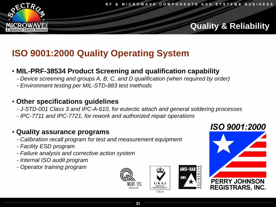
Quality & Reliability
ISO 9001:2000 Quality Operating System
• MIL-PRF-38534 Product Screening and qualification capability- Device screening and groups A, B, C, and D qualification (when required by order)- Environment testing per MIL-STD-883 test methods
• Other specifications guidelines- J-STD-001 Class 3 and IPC-A-610, for eutectic attach and general soldering processes- IPC-7711 and IPC-7721, for rework and authorized repair operations
• Quality assurance programs- Calibration recall program for test and measurement equipment- Facility ESD program- Failure analysis and corrective action system- Internal ISO audit program- Operator training program
32
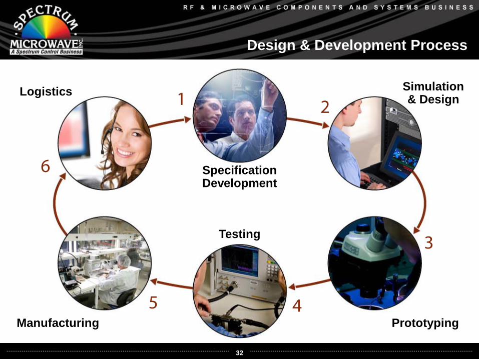
Design & Development Process
SpecificationDevelopment
Simulation& Design
Prototyping
Testing
Logistics
Manufacturing
1 2
3
45
6
3300