
Spectrum Glass System Installation Instructions Table … · Spectrum Glass System Installation...
7
Spectrum Glass System Installaon Instrucons Atlantis Rail’s Spectrum Glass System is an easy to install railing product. It utilizes surface mounted square posts (available in 36” and 42” heights) adapted with our glass panel connectors (flat) to accept 3/8” or 1” glass infill. The Spectrum System is offered in a standard black or metallic silver color option. Other colors are available. Ask your Sales Representative for details. Customers must source their own flat hardwood top rail (minimum of 2” x 4”). ATLANTIS RAIL Contact Information: Atlantis Rail Systems 70 Armstrong Road 3900 Civic Center Drive Plymouth, MA 02360 North Las Vegas, NV 89030 (800) 541-6829 or (508) 732-9191 (508) 732-9798 www.atlantisrail.com Warning Note Hints Tools ATLANTIS RAIL PROVIDES THE POSTS AND GLASS CONNECTORS ONLY. ATLANTIS RAIL DOES NOT OFFER GLASS PANELS AS PART OF THE SPECTRUM GLASS SYSTEM. Required & Recommended Power Drill #2 Phillips Driver Bit 7/32” Drill Bit 1/2” Socket & Ratchet Tape Measure Carpenter’s Square Pencil Safety Glasses Work Gloves Level Vice Grips Silicone Caulk 7/16” Open Wrench 4mm, 5/16” Allen Wrench ©2018 All Rights Reserved ▪ Atlantis Rail Systems is a registered trademark of Suncor Stainless, Inc. ▪ www.atlantisrail.com 1 May 2018 Table of Contents Tools 1 Tips for a Successful Installation 2 Glass Panel Connector Component 2 Additional Components 2 Surface Mount Post Options 3 Surface Mount Posts Preparation 3 Installing the Surface Mount Posts 4 Installing the Top Rail 5 Installing the Glass Infill 5 Additional Components 6 Spectrum Glass Post Kit Heights 7 Spectrum Glass System Specifications 7
Transcript of Spectrum Glass System Installation Instructions Table … · Spectrum Glass System Installation...

Spectrum Glass System Installation InstructionsAtlantis Rail’s Spectrum Glass System is an easy to install railing product. It utilizes surface mounted square posts (available in 36” and 42” heights) adapted with our glass panel connectors (flat) to accept 3/8” or 1” glass infill. The Spectrum System is offered in a standard black or metallic silver color option. Other colors are available. Ask your Sales Representative for details. Customers must source their own flat hardwood top rail (minimum of 2” x 4”).
ATLANTIS RAIL Contact Information:
Atlantis Rail Systems70 Armstrong Road 3900 Civic Center DrivePlymouth, MA 02360 North Las Vegas, NV 89030
(800) 541-6829 or (508) 732-9191 (508) 732-9798 www.atlantisrail.com
Warning Note Hints
Tools
ATLANTIS RAIL PROVIDES THE POSTS AND GLASS CONNECTORS ONLY. ATLANTIS RAIL DOES NOT OFFER GLASS PANELS AS PART OF THE SPECTRUM GLASS SYSTEM.
Required & Recommended
Power Drill #2 Phillips Driver Bit
7/32” Drill Bit 1/2” Socket& Ratchet
Tape Measure Carpenter’s Square
Pencil Safety Glasses Work Gloves
LevelVice Grips Silicone Caulk7/16” Open Wrench
4mm, 5/16” Allen Wrench
©2018 All Rights Reserved ▪ Atlantis Rail Systems is a registered trademark of Suncor Stainless, Inc. ▪ www.atlantisrail.com1 May 2018
Table of Contents
Tools 1Tips for a Successful Installation 2Glass Panel Connector Component 2
Additional Components 2Surface Mount Post Options 3Surface Mount Posts Preparation 3Installing the Surface Mount Posts 4Installing the Top Rail 5Installing the Glass Infill 5Additional Components 6Spectrum Glass Post Kit Heights 7Spectrum Glass System Specifications 7

Surface Mount Post Options
Tips for a Successful Installation
● Read the instructions completely before beginning the installation.
● Plan your railing project. Sketch your project with the actual measurements of your deck or balcony complete with post locations.
● Check carton(s) to determine part count is complete.● Installation is best accomplished with two (2) people.● Always wear personal protection equipment; safety
glasses, work gloves, etc.
ALWAYS REFER TO YOUR LOCAL BUILDING CODE OFFICIALS PRIOR TO INSTALLING ANY ATLANTIS RAIL SYSTEM TO ENSURE ALL CODE AND SAFETY REQUIREMENTS ARE MET. ATLANTIS RAIL SYSTEMS IS NOT RESPONSIBLE FOR IMPROPER OR NON-RECOMMENDED INSTALLATIONS.
©2018 All Rights Reserved ▪ Atlantis Rail Systems is a registered trademark of Suncor Stainless, Inc. ▪ www.atlantisrail.com2 May 2018
Glass Panel Connector Component
ATLANTIS RAIL SYSTEMS PROVIDES A VARIETY OF MOUNTING OPTIONS FOR POSTS AND RAILS USED IN OUR SYSTEMS. PRODUCTS OF THIS NATURE REQUIRE THAT MOUNTING SURFACES ARE CONSTRUCTED TO BE CONSIDERED STRUCTURAL PER BUILDING CODE DEFINITION FOR THE SURFACE MATERIAL USED. STRUCTURAL INTEGRITY AND BUILDING CODE COMPLIANCE OF MOUNTING SURFACES ARE THE RESPONSIBILITY OF THE END USER AND / OR INSTALLER. THE USE OF ANY OF OUR MOUNTING METHODS ARE AT THE OPTION AND DECISION OF THE END USER AND / OR INSTALLER AND SHOULD BE SELECTED TO MATCH THE STRUCTURAL MATERIAL USED TO CREATE THE MOUNTING SURFACE.
Glass Panel Connector - FlatS0950-F010
Additional Components
Wide Mounting Plate ADA Mounting Clamp Reinforcing Channel
Spectrum Surface Mount Glass End Post Kit Components
A. Spectrum Square End Post B. Top Mounting Plate Assembly C. Glass Panel Connector (Flat) D. Base Cover
A
B
C
NOTE: Surface mounting fasteners & hardware sold separately.
D
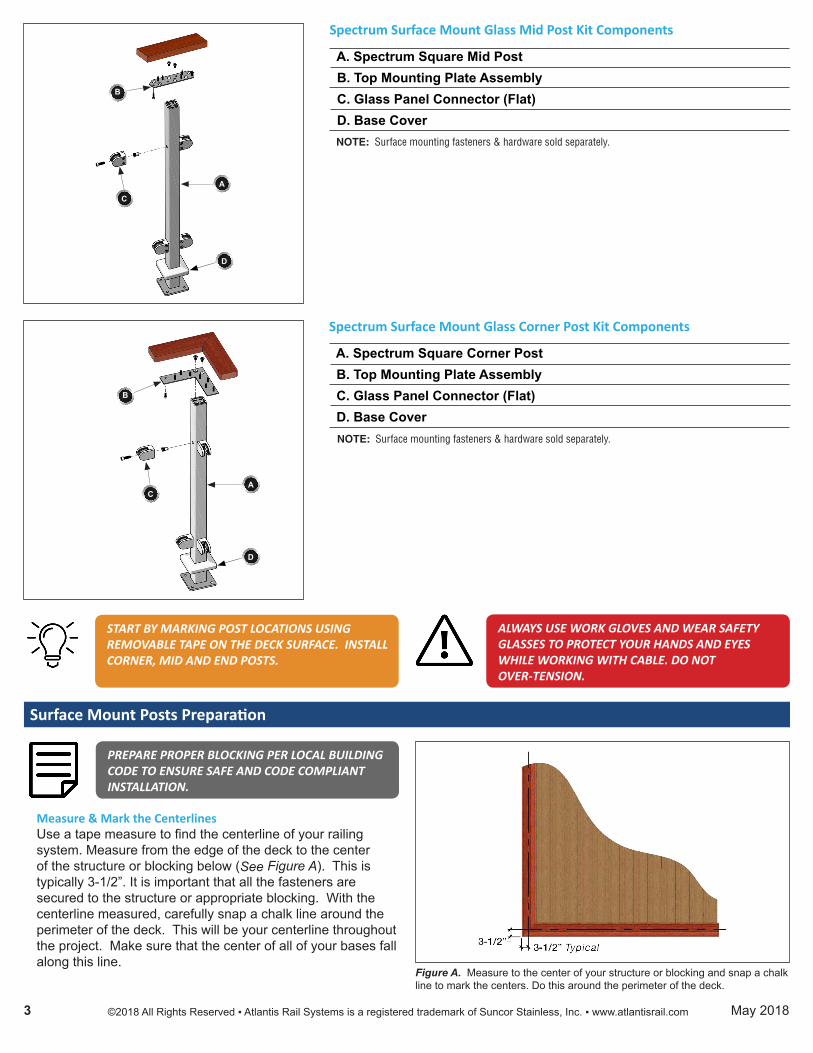
START BY MARKING POST LOCATIONS USING REMOVABLE TAPE ON THE DECK SURFACE. INSTALL CORNER, MID AND END POSTS.
ALWAYS USE WORK GLOVES AND WEAR SAFETY GLASSES TO PROTECT YOUR HANDS AND EYES WHILE WORKING WITH CABLE. DO NOT OVER-TENSION.
©2018 All Rights Reserved ▪ Atlantis Rail Systems is a registered trademark of Suncor Stainless, Inc. ▪ www.atlantisrail.com3 May 2018
Surface Mount Posts Preparation
PREPARE PROPER BLOCKING PER LOCAL BUILDING CODE TO ENSURE SAFE AND CODE COMPLIANT INSTALLATION.
Figure A. Measure to the center of your structure or blocking and snap a chalk line to mark the centers. Do this around the perimeter of the deck.
Measure & Mark the CenterlinesUse a tape measure to find the centerline of your railing system. Measure from the edge of the deck to the center of the structure or blocking below (See Figure A). This is typically 3-1/2”. It is important that all the fasteners are secured to the structure or appropriate blocking. With the centerline measured, carefully snap a chalk line around the perimeter of the deck. This will be your centerline throughout the project. Make sure that the center of all of your bases fall along this line.
A
B
C
Spectrum Surface Mount Glass Mid Post Kit Components
A. Spectrum Square Mid Post B. Top Mounting Plate Assembly C. Glass Panel Connector (Flat) D. Base Cover
NOTE: Surface mounting fasteners & hardware sold separately.
D
Spectrum Surface Mount Glass Corner Post Kit Components
A. Spectrum Square Corner Post B. Top Mounting Plate Assembly C. Glass Panel Connector (Flat) D. Base Cover
A
B
C
NOTE: Surface mounting fasteners & hardware sold separately.
D

Assemble the Corner PostsAttach the corner mounting plate to each post (See Figure B), using the center hole pattern, with two (2) 1/4” flat head machine screws. Corners require one (1) post. Make sure that the glass panel connectors are running parallel with the long side of the plate on both sides.
Figure B. Attach the corner mounting plate to each corner post with two (2) 1/4” flat head machine screws.
TO ENSURE CODE COMPLIANCE, ATLANTIS RAIL DOES NOT RECOMMEND EXCEEDING 4’ (48”) ON-CENTER BETWEEN CABLE SUPPORT POSTS. DO NOT EXCEED 48’ BETWEEN TERMINATION HARDWARE.
Installing the Surface Mount Posts
Install the Corner & End PostsBeginning with corner posts, place the bases along the centerline being careful to make sure the bases are properly oriented. Using the base as a template, mark the four (4) holes for the screws (See Figure C). Use a 7/32” drill bit to drill a pilot hole for the lag bolts. Take extra care to be sure the holes are drilled into joists or blocking.
With the holes pre-drilled, install the corner posts with the hex lag screws using a 1/2” socket and ratchet set. When installing the posts, constantly check for level. Once the posts are installed, apply silicone to the hex lag screws and secure the supplied hex lag screw caps to prevent moisture from getting to the hex lag screws (See Figure D). Slide the base cover onto the base BEFORE installing the glass panel connectors - flat (See Figure E). Check for level and adjust accordingly.
Repeat the steps above to install the end posts.Install the Mid PostsWhen you have the end and corner posts installed, measure the distance between the end and corner. Divide this measurement evenly to get the required number of sections. Mark the center locations for the mid post bases once again taking care that the base is located on the centerline and oriented properly. Follow the steps above to install the mid posts.
RepeatWhen you have the end and corner posts installed, measure the distance between the end and corner. Divide this measurement evenly to get the required number of sections. Repeat the above steps to install the mid posts.
Figure C. (Left) Use the base as a template and mark the four (4) holes for the screws.Figure D. (Center) Apply silicone to the hex lag screws once installed and secure the hex lag screw caps.Figure E. (Right) Slide the base cover onto the base BEFORE installing the cable.
IF INSTALLING CABLE STABILIZERS, PLEASE REFER TO THE CABLE STABILIZER INSTALLATION INSTRUCTIONS.
©2018 All Rights Reserved ▪ Atlantis Rail Systems is a registered trademark of Suncor Stainless, Inc. ▪ www.atlantisrail.com4 May 2018

Installing the Top Rail
Install the Top PlatesSecure the top plates to each of the posts using two (2) 1/4” -20 RH screws. For mid posts, use the hole pattern in the center of the plate (See Figure F). For end posts use the side hole patterns. Be sure to have the corner plates pre-assembled for ease of installation.
Install the Top RailCarefully measure and cut your top rail taking into account any mitering of joints you may need to do. Piece by piece; lay your top rail on the center of the mounting plate being sure that the top rail covers the top plate in its entirety. With the top rail in place, using a 7/32” drill bit, pre-drill for the wood screws that attach the top rail to the mounting plate. Use up to six (6) #10 pan head screws (supplied) to fasten the wooden top rail to the Spectrum posts (See Figure G).
Figure F. For mid posts, use the hole pattern in the center of the plate and secure using two (2) 1/4”-20 RH screws.
Figure G. Secure wooden top rail using up to six (6) #10 pan head screws.
Installing the Glass Infill
©2018 All Rights Reserved ▪ Atlantis Rail Systems is a registered trademark of Suncor Stainless, Inc. ▪ www.atlantisrail.com5 May 2018
Figure H. (LEFT) Attach the glass panel connectors (flat) to the posts.Figure I. (RIGHT) Place the glass up against the glass panel connectors and install cover plates.
Install the Glass Panel Connector - FlatWith a 4mm Allen wrench loosen the screws in the glass panel connector(s) and remove the cover plate(s). With a 5/16” Allen wrench place the 5/16” socket cap screw through the base of the glass panel connector, insert into the rivet nut that is installed in the post and tighten down (See Figure H). Once all the glass panel connectors are installed it’s time to install the glass panels.
Install the Glass PanelWith a partner insert the glass panel into the GlassPanel Connectors and ensure it is snug against the lip of the connectors (See Figure I). Each connector comes with rubber pads allowing glass thickness of 3/8” to 1/2” thick.
THE GLASS PANEL SITS 3” OFF THE DECK SURFACE. CUT A 3” HIGH BLOCK OF WOOD SO THAT YOU CAN SUPPORT THE BOTTOM EDGE OF THE GLASS PANEL ON WHILE FASTENING THE GLASS CONNECTOR COVERS.
METAL PINS SHEATHED IN RUBBER ARE INCLUDED WITH EACH CONNECTOR IF YOU DESIRE TO INSTALL THEM. THE METAL PINS ACT AS A STRUCTURAL FEATURE LOCKING THE GLASS PANEL IN PLACE. THE GLASS MUST BE ORDERED WITH HOLES ALLOWING THE PINS TO PASS THROUGH.
With a 4mm Allen wrench tighten the screws in the glass panel connector(s).

Additional Components
Wide Mounting Plate - S0904-XX53The Wide Mounting Plate (part number S0904-XX53) is twice the width of the standard mounting plate and is used in applications where a wider top rail is desired.
Secure the plate to the post using two (2) 1/4” -20 RH screws. For mid posts, use the hole pattern in the center of the plate (See Figure J). For end posts use the side hole patterns.
Figure J. Use when a wider top rail is desired. For mid posts, use the hole pattern in the center of the plate and secure using two (2) 1/4”-20 RH screws.
Figure L. Attach the spacing block to the post before attaching the top mount-ing plate.
Figure M. (LEFT) Place the reinforcing channel in the center of the post on the top of the mounting plate.Figure N. (RIGHT Use the supplied fasteners to attach the channel and top mounting plate to the top rail.
BEFORE INSERTING THE U-SHAPE PIECE ONTO THE POST, MOISTEN THE PADS. THIS WILL ENABLE IT TO GLIDE EASIER OVER THE POST WHILE KEEPING THE PADS IN PLACE.
Attach the back piece and insert the screws. Using a 5/32” (or 4mm) Allen wrench, tighten the screws alternately a half turn at a time until the screws are fully tightened.
Reinforcing Channel - S0904-XX54This channel (part number S0904-XX54) is used in applications where the handrail needs additional reinforcement. The 36” surface mount Spectrum post requires a spacing block (part number S0904-XX58) for installation. If a spacing block is required (See Figure L), attach it to the post before attaching the top mounting plate.
The reinforcing channel is 48” in length and is ideal for 4’ post spacing. It can be cut to size if shorter spans are needed. Place the channel in the center of the post on top of the top mounting plate (See Figure L). Place the customer supplied top rail on top of the reinforcing channel. Use the supplied #10 wood screws to attach the channel and top mounting plate to the top rail (See Figure N). Using two (2) screws at either end of all exposed slots, fasten the channel to the top rail. Also, be sure to fasten through the top mounting plate where slots offer exposed top rail access.
Figure K. Insert the u-shape piece onto the post making sure the pads stay intact. Attach the back piece and tighten screws alternately until fully tightened.
ADA Mounting Clamp - S0904-XX60The ADA Mounting Clamp (part number S0904-XX60) fits snugly on the Spectrum post. To attach, insert the U-shape piece of the clamp onto the post making sure the pads stay intact (See Figure K).
©2018 All Rights Reserved ▪ Atlantis Rail Systems is a registered trademark of Suncor Stainless, Inc. ▪ www.atlantisrail.com6 May 2018

Spectrum Glass System Specifications
The Spectrum Glass System uses stainless steel surface mounted square posts with our glass panel connectors (flat) to accept 3/8” or 1” tempered glass infill. Customers must provide their own hard wood top rail and glass infill. Posts should be surface mounted securely enough to resist detachment.
Straight SectionsThe Spectrum System is offered in post heights of 36” or 42” for straight sections. It consists of square posts fascia mounted, customer supplied top rail and glass infill.
RAILING HEIGHTS ARE OFFERED IN THESE DIMENSIONS DUE TO NATIONWIDE BUILDING CODES. HOWEVER, ATLANTIS RAIL CAN SUPPLY CUSTOM HEIGHTS/LENGTHS UPON REQUEST.
Between Post LengthsAtlantis Rail recommends staying within 4’ - 5’ (Max.) section lengths to maintain structural integrity.
Railing FinishThe Spectrum System is offered in standard and special order colors to fit any application.
InfillThe glass panel connectors (flat) accept 3/8” or 1” glass infill. Again customers must provide their own glass infill.
* “XX” in the part number is the color designation. Replace with “BK” for black, “MT” for metallic silver or “SP” for one of the special colors.
Spectrum Glass System Product SpecificationsComponents
Product Description Dimensions Fasteners NotesS0905-XX36-GE* 36” Surface Mount End Post Kit 36” 316 stainless steel Hex Lag Screws Fasteners not includedS0905-XX36-GM* 36” Surface Mount Mid Post Kit 36” 316 stainless steel Hex Lag Screws Fasteners not includedS0905-XX36-GC* 36” Surface Mount Corner Post Kit 36” 316 stainless steel Hex Lag Screws Fasteners not includedS0905-XX42-GE* 42” Surface Mount End Post Kit 42” 316 stainless steel Hex Lag Screws Fasteners not includedS0905-XX42-GM* 42” Surface Mount Mid Post Kit 42” 316 stainless steel Hex Lag Screws Fasteners not includedS0905-XX42-GC* 42” Surface Mount Corner Post Kit 42” 316 stainless steel Hex Lag Screws Fasteners not includedS0950-F010 Glass Panel Connector (Flat) 3/8” to 1/2” 316 stainless steel -- Neoprene Pads
©2018 All Rights Reserved ▪ Atlantis Rail Systems is a registered trademark of Suncor Stainless, Inc. ▪ www.atlantisrail.com7 May 2018
Spectrum Glass Post Kit HeightsPart Number Post Description Actual Post Rendered Height From Height Rail Height SurfaceS0905-XX36-GE* 36” Surface Mount End Post Kit 34.50” 36” 34.50”S0905-XX36-GM* 36” Surface Mount Mid Post Kit 34.50” 36” 34.50”S0905-XX36-GC* 36” Surface Mount Corner Post Kit 34.50” 36” 34.50”S0905-XX42-GE* 42” Surface Mount End Post Kit 40.50” 42” 40.50”S0905-XX42-GM* 42” Surface Mount Mid Post Kit 40.50” 42” 40.50”S0905-XX42-GC* 42” Surface Mount Corner Post Kit 40.50” 42” 40.50”