SPECTRA 1727 V1 - imotionsecurite.com 1727 3 2.3 AC POWER Do not use switch-controlled outlets to...
20
SPECTRA 1727 V1.10 1727 COMPLETE INSTALLATION MANUAL Reference, Installation and Programming
Transcript of SPECTRA 1727 V1 - imotionsecurite.com 1727 3 2.3 AC POWER Do not use switch-controlled outlets to...

SPECTRA 1727 V1.10
1727
COMPLETE INSTALLATION MANUALReference, Installation and Programming


TABLE OF CONTENTSIntroduction.........................................................................................................................................................2
Features ..............................................................................................................................................................................................2Specifications ......................................................................................................................................................................................2
Spectra 1727 Control Panel ................................................................................................................................................................................. 2Spectra 1686H and 1686V 10-Zone LED Keypads ............................................................................................................................................. 2
Programming Methods ........................................................................................................................................................................2Single Digit Entry Method ..................................................................................................................................................................................... 2Multiple Feature Select Programming Method ..................................................................................................................................................... 2
Installation ..........................................................................................................................................................2Location and Mounting ........................................................................................................................................................................2Earth Ground .......................................................................................................................................................................................2AC Power ............................................................................................................................................................................................3Backup Battery ....................................................................................................................................................................................3Auxiliary Power Terminals ...................................................................................................................................................................3Bell Output Connections ......................................................................................................................................................................3Programmable Output (PGM) Connections and Programming ...........................................................................................................3Zone Inputs .........................................................................................................................................................................................4Keypad Installation ..............................................................................................................................................................................4Keypad Zone Installation .....................................................................................................................................................................4Keypad Tamper ...................................................................................................................................................................................4
Zone Programming ............................................................................................................................................5Zone Options .......................................................................................................................................................................................5
Entry Delay ........................................................................................................................................................................................................... 5Bypass Enabled Zone .......................................................................................................................................................................................... 5Stay Zone ............................................................................................................................................................................................................. 524-Hour Burglary Zone ......................................................................................................................................................................................... 5Instant Zone ......................................................................................................................................................................................................... 5Follow Zone .......................................................................................................................................................................................................... 5
Fire Zone Programming .......................................................................................................................................................................6Zone Speed .........................................................................................................................................................................................6
System Options .................................................................................................................................................6Exit Delay Timer ..................................................................................................................................................................................6Entry Delay Timer ................................................................................................................................................................................6Bell Cut-off Timer..................................................................................................................................................................................6Panic Alarm .........................................................................................................................................................................................6Arming options .....................................................................................................................................................................................6
Auto Force Arming ............................................................................................................................................................................................... 6One-touch Arming ................................................................................................................................................................................................ 7Stay Arming with Delay ........................................................................................................................................................................................ 7
Reset Jumper ......................................................................................................................................................................................7Bell Relay Option .................................................................................................................................................................................7
Access Codes ....................................................................................................................................................7Access Code Length ...........................................................................................................................................................................7Installer Code .....................................................................................................................................................................................7System Master Code ..........................................................................................................................................................................7User Access Codes .............................................................................................................................................................................8
User Operation ...................................................................................................................................................8Disarming & Deactivating an Alarm .....................................................................................................................................................8Regular Arming ....................................................................................................................................................................................8Stay Arming .........................................................................................................................................................................................8Force Arming .......................................................................................................................................................................................8Bypass Programming ..........................................................................................................................................................................8
Bypass Recall ...................................................................................................................................................................................................... 9User Access Codes .............................................................................................................................................................................9Panic Alarms .......................................................................................................................................................................................10Alarm Memory Display ........................................................................................................................................................................10Programming Chime Zones .................................................................................................................................................................10Keypad Muting ....................................................................................................................................................................................10
Programming Guide ..........................................................................................................................................10Hardware Connections .....................................................................................................................................13
Spectra 1727 1

1: INTRODUCTION
1.1 FEATURES• 6 Programmable Zones: 4 Zones, 1 Keypad Zone, 1 Fire/24Hr. Burglary Zone• 1 Installer Code and 8 User Codes (1 System Master and 7 User Codes)• 2 Programmable Outputs• Regular Arming, Stay Arming, Force Arming, One-touch Arming, and Bypass Programming• 5A Relay• Keypad Activated Panic Alarm
1.2 SPECIFICATIONS1.2.1 SPECTRA 1727 CONTROL PANEL
AC Power: 16Vac transformer with 20VA rating, 50/60HzBattery: 12Vdc, 4AhAux. Power: 12Vdc output, 400 mA max., shutdown at 1A (fused)Bell Output: 1A, shutdown at 3A (fused)Battery Output: fused at 5APGM1 Output: 50mA maximum, 30mA recommendedPGM2 Output: 50mA maximum, 30mA recommended
1.2.2 SPECTRA 1686H AND 1686V 10-ZONE LED KEYPADSPower Input: 9-16VdcZones: 1 Standard Keypad ZoneCurrent Consumption: 62 to 116mA
1.3 PROGRAMMING METHODS Use the Programming Guide on page 10 to keep track of how the sections were programmed. We recommend that you read this entire manualbefore you begin programming.
1.3.1 SINGLE DIGIT ENTRY METHODSingle Digit Data Entry is used in sections [10], [11], [12] and [13]. After entering Programming Mode as described in the shaded boxabove, in sections [10] to [12] you will enter a Decimal value from 00 to 99 representing seconds and in section [13] you will enter twosingle digits each representing a PGM option. The required data will be explained in the respective sections of this manual. Once youhave entered the required data, the control panel will save and exit the section, which returns programming to STEP 3.
1.3.2 MULTIPLE FEATURE SELECT PROGRAMMING METHODMultiple Feature Select Programming is used in sections [14], [15], [16], [17], [18], [19], and [20].
For sections [14], [15], [16], [17], and [18] each key from [1] to [6] represents a zone from [1] to [6]. For sections [19] and [20] each key from [1] to [8] represents an option.
After entering Programming Mode as described in the shaded box above, press the key corresponding to the desired zone or optionand the corresponding key will illuminate†. This means it is selected. When you press the key again, it will extinguish and it will no longerbe selected. Press the keys as many times as you need to select the desired zones or options. Press the [ENTER] key to save.
†patented. See page 15.
2: INSTALLATION
This equipment must be installed and maintained by qualified service personnel only.
2.1 LOCATION AND MOUNTINGRefer to the connection drawing on page 13. Push the four white nylon mounting studs into the back of the cabinet before mounting it to the wall.Pull all cables into the cabinet and prepare them for connection before attaching the circuit board to the studs. The installation site should be dry,close to an AC source and ground connection, and not easily accessible to intruders. Leave at least 2" (5cm) around the cabinet to permitadequate ventilation and heat dissipation.
2.2 EARTH GROUNDConnect the EARTH terminal from the control panel to the cabinet and cold water pipe or grounding rod as required by local electrical codes.
How Do I Enter Control Panel Programming Mode?STEP 1: Press [ENTER]STEP 2: Enter your [INSTALLER CODE] (default: 0000/000000)STEP 3: Enter the 2-digit [SECTION] you wish to programSTEP 4: Enter the required [DATA]
2 Complete Installation Manual

2.3 AC POWERDo not use switch-controlled outlets to power the transformer. Connect the 16.5VAC 40VA transformer as shown in Figure 8-1: PCB Layout onpage 13.
2.4 BACKUP BATTERYComplete all the wiring before connecting AC power and the battery. After establishing AC power, connect the 12VDC 4Ah rechargeable acid/lead or gel cell backup battery by connecting the red battery lead to the positive battery terminal (RED) and the black battery lead to the negativebattery terminal (BLK) as shown in Figure 8-1: PCB Layout on page 13. When installing, verify proper polarity as reversed connections will blowthe fuse.
2.5 AUXILIARY POWER TERMINALSThe auxiliary power supply terminals provide 400mA and can be used to power motion detectors and keypads in the security system. A 1A fuseprotects the power supply against current overload, which must be replaced if the current exceeds 1A. Therefore, the combined currentconsumption of devices connected to the auxiliary power supply should not exceed 1A.
2.6 BELL OUTPUT CONNECTIONSBells, sirens and other warning devices requiring a steady voltage output during alarms are powered by the bell relay and the bell output, whichis protected by a 3A fuse. Connect the siren’s positive lead to the panel’s BELL + terminal, the negative lead to the relay output NO or NC terminals,and connect a wire from the relay’s COM terminal to the AUX - terminal (see Figure 8-1: PCB Layout on page 13). Also, see Bell Relay Optionon page 7.
2.7 PROGRAMMABLE OUTPUT (PGM) CONNECTIONS AND PROGRAMMINGSection [13]The Spectra 1727 control panel includes two programmable outputs (PGMs) that provide a maximum of 50mA each. When a specific eventoccurs in the system, a PGM can reset smoke detectors, activate strobe lights, open/close garage doors and much more. Connect the PGMsaccording to Figure 8-3: PGM Connections on page 14.
In section [13] you program the event that will trigger the PGMs. The PGM will remain activated as long as the event is occurring. The first digit inthe section controls PGM 1 and the second digit controls PGM 2. The available events are listed in Table 2 on page 4. For example, if you wantto program PGM 1 to activate during the Exit Delay and PGM2 to activate during an alarm, in section [13] program [0] then [5]. The default is setat 3/3 (PGM1 and PGM2 activate when the [PG] key is pressed.
Modules Current Consumption
Spectra 1686H and 1686V 10-zone LED Keypad† 62mA typical 116mA maximum
Motion Detectors (see detector’s instructions for details)†patented. See page 15
10 to 50mA typical
Spectra 1727 3

2.8 ZONE INPUTSDetection devices such as motion detectors and door contacts are connected to the control panel's zone input terminals labelled Z1, Z2, Z3, Z4and FIRE as shown in Figure 8-2: Zone Connections on page 14. Once the zones are connected, the associated zone's parameters must bedefined. For more information, please refer to Zone Programming on page 5.
The FIRE input, which is recognized as zone 6, can be connected as a fire zone or a 24-hour burglary zone. Fire zones must use a 1kΩ EOLresistor. If a line short occurs or if the smoke detector becomes active, whether the system is armed or disarmed, the control panel will generatean alarm on this zone.
2.9 KEYPAD INSTALLATIONOnly the 1686V and the 1686H Spectra Keypads are compatible with the Spectra 1727 control panel. Remove the keypad’s back cover and wirethe GRN, YEL, RED, and BLK terminals to the corresponding terminals on the control panel as shown in Figure 8-1: PCB Layout on page 13.
2.10 KEYPAD ZONE INSTALLATIONThe keypad has one zone input terminal that allows you to connect one motion detector or one door contact directly to the keypad. The keypadzone is recognized as zone 5. Only one keypad zone can be used per Spectra 1727 control panel. The keypad communicates the status of thekeypad zone to the control panel once the device is connected as shown in Figure 8-1: PCB Layout on page 13 and the zone’s parameters aredefined (see section 3.2). For example, a door contact located at the front door can be wired directly to the input terminal of the keypad instead ofwiring it back to the control panel.
2.11 KEYPAD TAMPERIf the keypad has a tamper switch, the state of the tamper is displayed on zone 5. The control panel cannot differentiate between the openkeypad zone and an open keypad tamper.
Table 1: PGM Events
PGM Event Description
Exit Delay The PGM activates during the Exit Delay.
Armed The PGM activates while the system is armed.
Ready The PGM activates while the READY LED is illuminated.
“PG” Key The PGM activates when the PG key is pressed and deactivates when the key is pressed again.
Fire Alarm The PGM activates during a Fire Alarm.
Audible Alarm The PGM activates during any alarm.
Strobe The PGM activates while the ARM LED flashes in alarm.
Entry Delay/Exit Delay/Alarm The PGM activates during the Entry Delay, the Exit Delay and during an alarm.
Exit Delay/Armed The PGM activates during the Exit Delay or while the system is armed.
Entry Delay/Alarm The PGM activates during the Entry Delay or during an alarm.
Regular Armed The PGM activates while the system is Regular Armed.
Table 2: PGM Options
Option PGM 1 EventsFirst Digit
PGM 2 EventsSecond Digit
[0] Exit Delay Exit Delay
[1] Armed Armed
[2] Ready Ready
[3] “PG” Key “PG” Key
[4] Fire Alarm Fire Alarm
[5] Alarm Alarm
[6] Strobe Strobe
[7] Entry Delay/Exit Delay/Alarm Entry Delay/Exit Delay/Alarm
[8] Exit Delay/Armed Entry Delay/Alarm
[9] Regular Arming Entry Delay/Alarm
4 Complete Installation Manual

3: ZONE PROGRAMMING
3.1 ZONE OPTIONSSections [14], [15], [16], [17], and [18]Each section from [14] to [18] represents a specific Zone Option. Enter the desired section and use Multiple Feature Select Programming toselect the zones from 1 to 5 that will programmed with the Zone Option. Zone 6 is programmed as a 24-Hour Burglary Zone or a Fire Zone only(see section 3.2). To select a zone press the corresponding key. Selected zones will illuminate. For example, if you want zone 2 to be a StayZone, in section [18] press the [2] key to illuminate it. To remove the option from the zone, press the key corresponding to the zone so the keyextinguishes.
3.1.1 ENTRY DELAYZones that are not selected in sections [15] to [17] will be defined with the Entry Delay Option. For example, if you want Zone 1 to beprogrammed with the Entry Delay Option, make sure key [1] is not illuminated in sections [15], [16] and [17]. The Entry Delay Timeris programmed in section [11] (see section 4.2). All zones are Entry Delay by default.
3.1.2 BYPASS ENABLED ZONESection [14]When using the Bypass Programming feature or Force Arming (see section 6.4), only zones with the option Bypass Enabled can bebypassed. Select the zones from 1 to 5 to be Bypass Enabled. Zone 6 is a 24-Hour Zone or a Fire Zone (see section 3.2) and cannotbe Bypass Enabled.
3.1.3 STAY ZONESection [18]Zones with the Stay Zone option enabled will be bypassed when the system is Stay Armed (see section 6.3). Select the zones from 1to 6 to be Stay Zones.
The Zone Options 24-Hour Zone, Instant Zone and Follow Zone cannot be programmed on the same zone. Each zone can beprogrammed with only one of these Zone Options:
3.1.4 24-HOUR BURGLARY ZONESection [15]Whenever a 24-Hour Burglary Zone opens, whether the system is armed or disarmed, the control panel will immediately generate analarm. Select the zones from 1 to 5 to be 24-Hour Zones. Zone 6 is already a 24-Hour Zone or a Fire Zone (see section 3.2). Also,refer to Zone Speed (see section 3.3).
3.1.5 INSTANT ZONESection [16]When an armed Instant Zone opens, the control panel immediately generates an alarm. Instant Zones are commonly used forwindows, patio doors, skylights and other perimeter type zones. Select zones from 1 to 5 to be Instant Zones. Zone 6 is a 24-HourZone or a Fire Zone (see section 3.2) and cannot be programmed as an Instant Zone. Also, refer to Zone Speed (see section 3.3).
3.1.6 FOLLOW ZONESection [17]When an armed Follow Zone opens, the control panel will immediately generate an alarm, unless an Entry Delay zone opens first: • If an armed Follow Zone opens after an Entry Delay zone opens, the control panel waits until the Entry Delay Timer has elapsed
before generating an alarm. If the system is disarmed during the Entry Delay, the alarm is cancelled.• If an armed Follow Zone opens after more than one Entry Delay zone opens, the control panel will wait until the Entry Delay
Timer of the zone that opened first has elapsed before generating an alarm. If the system is disarmed during the Entry Delay, the alarm is cancelled.
This feature is commonly used when a motion detector is protecting the area occupied by the entry point keypad. This will prevent themotion detector from causing an alarm when a user enters through the entry point to disarm the system. Select the zones from 1 to 5to be Follow Zones. Zone 6 is a 24-Hour Zone or a Fire Zone (see section 3.2) and cannot be programmed as a Follow Zone. Also,refer to Zone Speed (see section 3.3).
Table 3: Zones
Control Panel Inputs Zone Number KeyZ1 Zone 1 [1]Z2 Zone 2 [2]Z3 Zone 3 [3]Z4 Zone 4 [4]Keypad Zone/Keypad Tamper Zone 5 [5]Fire Zone 6 [6]
Spectra 1727 5

3.2 FIRE ZONE PROGRAMMINGSection [20] option [4]When option [4] is disabled, the control panel will recognize the zone as a 24Hr. Burglary Zone (see section 3.1.4). When option [4] is enabled,the control panel will recognize zone 6 as a Fire Zone, enabling smoke detectors connected as shown in Figure 8-2: Zone Connections on page14. Fire zones must use a 1kΩ EOL resistor. If there is a line short or if the smoke detector becomes active, whether the system is armed ordisarmed, the control panel will generate an alarm. Alarms are always audible, regardless of other settings. Fire alarms will generate anintermittent (pulsed) bell/siren output signal as demonstrated in Figure 3-1: Bell Output during Fire Alarm.Option [4] OFF: Zone 6 is a 24Hr. Burglary Zone (default)Option [4] ON: Zone 6 is a Fire Zone
Figure 3-1: Bell Output during Fire Alarm
3.3 ZONE SPEEDSection [19] option [1]The Zone Speed defines how quickly the control panel will respond to an open zone. The control panel will not display an open zone on thekeypad or generate an alarm until the programmed Zone Speed has elapsed. All other zone definitions and options do not come into effect untilthe Zone Speed has elapsed. This feature prevents any momentary glitches from causing an alarm.
Option [1] OFF: Zone Speed is 600ms (slow) (default)Option [1] ON: Zone Speed is 20ms (fast)
It is recommended to avoid using option [1] ON for Keypad Zones.
4: SYSTEM OPTIONS
4.1 EXIT DELAY TIMERSection [10]After entering the required arming sequence (i.e. User Access code), the Exit Delay Timer determines the amount of time a user has to leave theprotected area before the control panel arms the system. The Exit Delay applies to all zones in the system. The keypad will beep rapidly and theREADY LED will flash during the Exit Delay. Key in the desired two-digit value from 00 to 99 seconds into section [10] (30 seconds by default).
4.2 ENTRY DELAY TIMERSection [11]When the system is armed and a zone defined with the Entry Delay Option opens (see section 3.1), the control panel will generate an alarm afterthe programmed Entry Delay Timer has elapsed if the system is not disarmed. This is to provide users with enough time to enter the protectedarea and disarm the system. To program the Entry Delay Timer, key in the desired 2-digit delay value (00 to 99 seconds) into section [11] (45seconds by default). Entry Delay zones are commonly used at the entry/exit points of the protected area (i.e. front/back door, garage, etc.).
4.3 BELL CUT-OFF TIMERSection [12]After an audible alarm, the bell/siren output will deactivate when the system is disarmed or when the Bell Cut-off Timer has elapsed, whichevercomes first. Key in the desired two-digit value from 00 to 99 minutes into section [12] (04 minutes by default).
4.4 PANIC ALARMSection [19] option [6]In case of emergency, the Spectra 1727 system provides one panic alarm. This panic alarm, if enabled, will immediately generate an alarm afterpressing and holding the [1] and [3] keys for two seconds. In the Alarm Memory (see section 6.8) the [8] key will illuminate to indicate thatsomeone activated the Panic Alarm.Option [6] OFF: Panic Alarm is disabled (default)Option [6] ON: Panic Alarm is enabled
4.5 ARMING OPTIONS4.5.1 AUTO FORCE ARMINGSection [19] option [7]With this feature enabled, the control panel will always Force arm instead of Regular arm regardless of the User Access Code’s programming. Ininstallations where the user must Force arm when leaving the protected area, this feature allows users to Force arm without pressing the[FORCE] key before entering their User Access Code. Option [7] OFF: Auto Force Arming is disabled (default)Option [7] ON: Auto Force Arming is enabled
6 Complete Installation Manual

4.5.2 ONE-TOUCH ARMINGSection [19] options [3] and [5]The One-touch Arming Feature allows users to Regular or Stay Arm the system without having to enter access codes. To arm the system, pressand hold the [ENTER] key for approximately 2 seconds. For more information concerning Regular and Stay Arming see section 6.2 and section6.3.Option [3] OFF: One-touch Arming is Regular Arming (default)Option [3] ON: One-touch Arming is Stay Arming
Option [5] OFF: One-touch Arming is disabled (default)Option [5] ON: One-touch Arming is enabled4.5.3 STAY ARMING WITH DELAYSection [19] option [8]When Stay Arming (see section 6.3) with this option enabled, all armed zones become Entry Delay zones. For example: the system is StayArmed and you trigger a motion detector that is not a Stay Zone. Normally the system would go into alarm, but, since all armed zones are EntryDelay Zones, the system starts the Entry Delay Timer to allow you time to disarm the system. Option [8] OFF: Stay Arming with Delay disabled (default)Option [8] ON: Stay Arming with all armed zones as Entry Delay zones
4.6 RESET JUMPERSection [20] option [1]Performing a jumper reset will clear and reset the Installer Code. To do so:
1) Enable option [1] in section [20].2) Remove battery and AC power from the control panel.3) Set the RESET jumper to on by placing a jumper on the RESET pins of the control panel.4) Re-connect AC and battery power to the control panel.5) Wait 10 seconds and remove the jumper.6) Disable option [1] in section [20] (Recommended).Option [1] OFF: Reset Jumper disabled Option [1] ON: Reset Jumper enabled (default)
As a preventive measure, we recommend that you remove the jumper, or turn off option [1] to avoid losing the Installer Code in the caseof an unexpected power loss.
4.7 BELL RELAY OPTIONSection [20] option [3]When option [3] is enabled, the Bell Relay remains in its normal state. When an alarm occurs, it will toggle to its opposite state. When option [3]is disabled, the Bell Relay remains in its opposite state. When an alarm occurs, it will toggle to its normal state.Option [3] OFF: The Bell Relay deactivates upon alarmOption [3] ON: The Bell Relay activates upon alarm (default)
5: ACCESS CODES
5.1 ACCESS CODE LENGTHSection [19] = System OptionsOption [4] OFF: 6-Digit Access Codes (default)Option [4] ON: 4-Digit Access CodesAll the access codes can be set to lengths of 4-or 6-digits. When the 4-digit option is selected, entering a 4-digit code will allow access. If the 6-digit option is selected, a 6-digit access code is required. If the Access Code Length is changed from four digits to six digits when access codeshave already been programmed, the control panel will automatically add 00 to the end of the code. For example, if the access code is 1234 andyou switch to 6 digits, the code will become 123400. Be sure to verify the access codes after switching from 4-digit access codes to 6-digit codes.When switching from six digits to four digits, the control panel will simply remove the final two digits of the access code. For example, 123456 willbecome 1234.
5.2 INSTALLER CODE (DEFAULT: 0000/000000) The Installer Code is used to enter the control panel's programming mode (see section 1.3) and program section [01] and sections [10] to[20]. The Installer Code can be 4 or 6 digits in length (see section 5.1) where each digit can be any value from 0 to 9. The Installer Code cannotbe used to program the Master or User Access Codes. To program the Installer Code press:
[ENTER] + [CURRENT INSTALLER CODE] + [01] + new 4- or 6-digit Installer Code
5.3 SYSTEM MASTER CODE (DEFAULT 1234/123400) The System Master Code can program the User Access Codes in sections [02] to [09], but not the User Code Options see Table 4 on page 10since they are pre-programmed and cannot be changed. The System Master Code can be 4 or 6 digits in length (see section 5.1), where eachdigit can be any digit from 0 to 9. To change the System Master Code press:
[ENTER] + [CURRENT SYSTEM MASTER CODE] + [02] + new 4- or 6-digit System Master Code
Spectra 1727 7

5.4 USER ACCESS CODESThe Spectra 1727 supports 9 access codes. Eight access codes are available for the users. Programming User Access Codes is explainedin more detail in section User Access Codes on page 9.
6: USER OPERATION
6.1 DISARMING & DEACTIVATING AN ALARMTo disarm an already armed system or to deactivate an alarm simply key in a valid access code. When an entry/exit point is opened (breached),it will set off the Entry Delay Timer. The system will not generate an alarm until the Entry Delay Timer elapses, giving users enough time to enterthe premises and disarm the system. Once the system is disarmed, the alarm is cancelled. Any user can disarm the system, except usersassigned Code 7 “Arm Only”.
6.2 REGULAR ARMINGThis method, commonly used for day-to-day arming, will arm all the zones in the system. If you make a mistake, the keypad will emit a RejectionBeep. When you have correctly armed the system, the Exit Delay Timer will start and the ARM1 LED will turn. Regular Arming can also beactivated using One-Touch Arming.
6.3 STAY ARMINGThis method allows users to remain in the protected area while partially arming the system. For example, when going to sleep at night, entry/exitpoints like doors and windows can be armed while other zones like motion detectors remain deactivated. Please note that Fire Zones cannot bebypassed.
If you make a mistake, the keypad will emit a Rejection Beep. When you have correctly Stay Armed the system, the Exit Delay Timer will start.The ARM1 LED will flash when the Exit Delay ends. Stay Arming can also be activated using One-Touch Arming. User Access Codes musthave the Stay Arming Option to Stay Arm the system.
6.4 FORCE ARMINGForce Arming arms the system without waiting for all zones to close. Any open Bypass Enabled zones at the time of arming will be ignored by thecontrol panel. If a zone closes while the system is armed, then the control panel will arm the zone so it will generate an alarm if breached. ForceArming is commonly used when a motion detector is protecting the area occupied by a keypad. When Force Arming the system and the motiondetector detects movement near the keypad, the control panel will ignore the zone and arm the system even if the zone is open.
If you make a mistake, the keypad will emit a Rejection Beep. When you have correctly Force Armed the system, the Exit Delay Timer will startand the ARM1 LED will turn on. Access Codes must have the Force Arming option to Force Arm the system.
6.5 BYPASS PROGRAMMINGBypass Programming allows users to program the alarm system to ignore specified zones the next time the system is armed. Please note thatFire Zones cannot be bypassed and the zones chosen must be programmed as Bypass Enabled.
How Do I Disarm the System or Deactivate an Alarm?
Key in your [ACCESS CODE]The ARM1 LED will turn off and the keypad will emit a Confirmation Beep.
How Do I Regular Arm?
1) Green READY LED must be illuminated. All zones in the system must be closed.
2) Key in a valid [ACCESS CODE]
How Do I Stay Arm?
1) All zones except Stay Zones must be closed.2) Press the [STAY] button3) Key in a valid [ACCESS CODE]
How Do I Force Arm?
1) Press the [FORCE] button2) Key in a valid [ACCESS CODE]
8 Complete Installation Manual
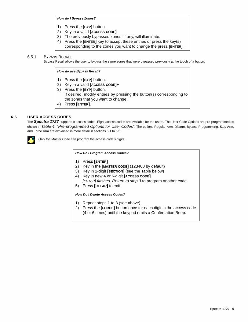
6.5.1 BYPASS RECALLBypass Recall allows the user to bypass the same zones that were bypassed previously at the touch of a button.
6.6 USER ACCESS CODESThe Spectra 1727 supports 9 access codes. Eight access codes are available for the users. The User Code Options are pre-programmed asshown in Table 4: “Pre-programmed Options for User Codes”. The options Regular Arm, Disarm, Bypass Programming, Stay Arm,and Force Arm are explained in more detail in sections 6.1 to 6.5.
Only the Master Code can program the access code’s digits.
How do I Bypass Zones?
1) Press the [BYP] button.2) Key in a valid [ACCESS CODE]3) The previously bypassed zones, if any, will illuminate.4) Press the [ENTER] key to accept these entries or press the key(s)
corresponding to the zones you want to change the press [ENTER].
How do use Bypass Recall?
1) Press the [BYP] button.2) Key in a valid [ACCESS CODE]+3) Press the [BYP] button.
If desired, modify entries by pressing the button(s) corresponding tothe zones that you want to change.
4) Press [ENTER].
How Do I Program Access Codes?
1) Press [ENTER]2) Key in the [MASTER CODE] (123400 by default)3) Key in 2-digit [SECTION] (see the Table below)4) Key in new 4 or 6-digit [ACCESS CODE]
[ENTER] flashes. Return to step 3 to program another code.5) Press [CLEAR] to exit
How Do I Delete Access Codes?
1) Repeat steps 1 to 3 (see above)2) Press the [FORCE] button once for each digit in the access code
(4 or 6 times) until the keypad emits a Confirmation Beep.
Spectra 1727 9

6.7 PANIC ALARMSThe panic alarm, if programmed, will immediately generate an alarm after pressing and holding the [1] and [3] keys for two seconds (see section4.4) (disabled by default).
6.8 ALARM MEMORY DISPLAYA record of the zones that were in alarm the last time the system was armed will be stored in memory. After disarming the system, press the[MEM] button to display the zones that were in alarm. To exit the Alarm Memory Display, press the [CLEAR] button. The control panel will erase thecontents of the alarm memory every time the system is armed.
Zone [5] will illuminate if an alarm has occurred on the keypad zone or if the keypad’s on-board tamper was triggered (see section 2.10).The control panel cannot distinguish the difference between the two. Zone [8] will illuminate if the panic alarm keys (see section 4.4)were pressed.
6.9 PROGRAMMING CHIME ZONESPress and hold any key from [1] to [5] for 3 seconds to activate or deactivate Chiming for zones 1 to 6. For example, press and hold the [1] keyto enable chiming on zone 1. If after pressing and holding a key, the keypad emits a confirmation beep, the chime feature has been enabled for thatzone. If the keypad emits a rejection beep, the chime feature has been disabled for the corresponding zone.
6.10 KEYPAD MUTINGPress and hold the [CLEAR] button for 3 seconds to enable or disable keypad muting. When muted, the keypad will only beep when a key ispressed and when the keypad emits a rejection or confirmation beep. All other beep functions are disabled.
7: PROGRAMMING GUIDETo program the Spectra 1727 control panel, use a keypad to enter the Programming Mode as shown below.
USER CODESSections [02] to [09] can only be programmed by the System Master Code (see section 5.4).
Table 4: Pre-programmed Options for User Codes
Section User Codes CanChange Code
Can Reg. Arm
Can Disarm
CanBypass Arm
CanStay Arm
CanForce Arm
[01] Installer Code
[02] Master Code 3 3 3 3 3 3[03] User Code 01 3 3 3 3 3[04] User Code 02 3 3 3 3 3[05] User Code 03 3 3 3 3 3[06] User Code 04 3 3[07] User Code 05 3 3[08] User Code 06 3 3[09] User Code 07 3
DEFAULT INSTALLER CODE: 0000/000000 DEFAULT SYSTEM MASTER CODE: 1234/123400
How Do I Enter Programming Mode?STEP 1: Press [ENTER]
STEP 2: Enter your [INSTALLER CODE] (default: 0000/000000) or [SYSTEM MASTER CODE] (default: 1234/123400)
STEP 3: Enter the 2-digit [SECTION] you wish to programSTEP 4: Enter the required [DATA]
Section #
[01] Installer Code[ENTER] + [CURRENT INSTALLER CODE] + [01] + new 4- or 6-digit Installer Code
10 Complete Installation Manual

SYSTEM TIMERSSection #
[10] ____/____EXIT DELAY TIMER (00 to 99 seconds) default: 30 seconds
[11] ____/____ENTRY DELAY TIMER (00 to 99 seconds) default: 45 seconds
[12] ____/____BELL CUT-OFF (00 to 99 minutes) default: 04 minutes
PGM PROGRAMMING
[13] ____/____PGM 1 / PGM 2 (default: 3 / 3)
[02] System Master Code
[03] User Code 01
[04] User Code 02
[05] User Code 03 These sections can only be programmed with the System Master Code
[06] User Code 04 [ENTER] + [SYSTEM MASTER CODE] + [SECTION] + new 4- or 6-digit code
[07] User Code 05
[08] User Code 06
[09] User Code 07
How Do I Program the PGMs?STEP 1: Press the [ENTER] keySTEP 2: Enter the [INSTALLER CODE] (Default: 0000/000000)STEP 3: Enter [13]STEP 4: Enter one digit representing the Activation/deactivation Event for PGM 1.STEP 5: Enter one digit representing the Activation/deactivation Event for PGM 2.
Table 5: PGM Programming
Option PGM 1 EventsFirst Digit
PGM 2 EventsSecond Digit
[0] Exit Delay Exit Delay
[1] Armed Armed
[2] Ready Ready
[3] “PG” Key “PG” Key
[4] Fire Alarm Fire Alarm
[5] Alarm Alarm
[6] Strobe Strobe
[7] Entry Delay/Exit Delay/Alarm Entry Delay/Exit Delay/Alarm
[8] Exit Delay/Armed Entry Delay/Alarm
[9] Regular Arming Entry Delay/Alarm
Spectra 1727 11

ZONE PROGRAMMING
*The Zone Options 24-Hour Zone, Instant Zone and Follow Zone cannot be programmed on the same zone. Each zone canbe programmed with only one of these Zone Options.
SYSTEM OPTIONSBold = Default Setting
How Do I Program the Zones?STEP 1: Press the [ENTER] keySTEP 2: Enter the [INSTALLER CODE] (Default: 0000/000000)STEP 3: Enter the 2-digit [SECTION] representing the Zone Option (all zones Entry Delay by default)STEP 4: Select zone(s) by pressing the corresponding key. Illuminated = Zone Option enabled for zone.STEP 5: Press the [ENTER] key
Section Zone OptionsInputs: Z1 Z2 Z3 Z4 Keypad Zone Fire
Zones: 1 2 3 4 5 6Press Key [1] [2] [3] [4] [5] [6]
[14] Bypass Enabled l l l l l[15] 24Hr. Burglary* l l l l l l[16] Instant* l l l l l[17] Follow* l l l l l[18] Stay Zone l l l l l
Entry Delay Sections [15], [16] and [17] must be off for the selected zone. Example: for an Entry Delay on zone 1, turn key [1] off in sections [15] to [17].
Force Zone Program the zone as Bypass Enabled (section [14]).
SECTION [19]: System OptionsOption OFF ON
[1] Zone Speed Slow (600ms) Fast (20ms)[2] Not used N/A N/A[3] One-touch Arming (see option [5]) Regular Arm Stay Arm[4] User Code Length 6 Digits 4 Digits[5] One-touch Arming (see option [3]) Disabled Enabled[6] Panic Keys ([1] & [3]) Disabled Enabled[7] Auto Force Arming Disabled Enabled[8] Stay Arming with all zones as Entry Delay zones Disabled Enabled
SECTION [20]: System OptionsOption OFF ON
[1] Reset Jumper Disabled Enabled[2] Not used N/A N/A[3] Alarm Relay Output Deactivates on Alarm Activates on Alarm[4] Zone 6 is defined as 24Hr. Zone Fire Zone[5] Not used N/A N/A[6] Not used N/A N/A[7] Not used N/A N/A[8] Not used N/A N/A
12 Complete Installation Manual

8: HARDWARE CONNECTIONS
Figure 8-1: PCB Layout
Spectra 1727 13

Figure 8-2: Zone Connections
Figure 8-3: PGM Connections
14 Complete Installation Manual

UL and C-UL WarningsUL AND C-UL INSTALLATION NOTESThis equipment is UL listed in accordance with standard UL1023 (Household Burglar -- Alarm Systems Units), standard UL985 (Household Fire WarningUnits) and standard CAN/C-UL S545 (Residential Fire Warning System Control Units). This equipment has the capability of being programmed with featuresnot verified for use in UL installations. To stay within these standards, the installer should use the following guidelines when configuring the system:
• All components of the system should be UL listed for the intended application.• If the system will be used for “Fire” detection, the installer should refer to NFPA Standards #72, Chapter 2. In addition, once installation is
complete, the local fire authority must be notified of the installation.• This equipment must be verified by a qualified technician once every three years.• All keypads must use a tamper switch.• Maximum allowed entry delay is 45 seconds.• Maximum allowed exit delay is 60 seconds.• Minimum 4 minutes for bell cut-off time.• The following features do not comply with UL requirements: Bypass Recall, Shabbat and “No AC Fail” display. • Do not connect the primary indicating device to a relay. The installer must use the bell output.• The metallic enclosure that houses the Spectra control panel must be grounded to the cold water pipe.• Use a UL/C-UL listed Siren: Wheelock model# 46T-12.• Use a UL/C-UL listed 12Vdc 4Ah rechargeable battery: YUASA model# NP7-12.• Transformer requirements: UL listed transformer - 16VAC 40VA• UL listed Basler Electronics Transformer - #BE156240CAA• CSA listed Basler Electronics Transformer - #BE116240AAA• The AUX, PGM and Keypad’s maximum current cannot exceed 200mA for UL installations.
All outputs are Class 2 or power-limited, except for the battery terminal. The Class 2 and power-limited fire alarm circuits shall be installed using CL3, CL3R,CL3P, or substitute cable permitted by the National Electrical Code, ANSI/NFPA 70.
WarrantyThe Seller warrants its products to be free from defects in materials and workmanship under normal use for a period of one year (unless otherwiseindicated). Except as specifically stated herein, all express or implied warranties whatsoever, statutory or otherwise, including without limitation, any impliedwarranty of merchantability and fitness for a particular purpose, are expressly excluded. Because Seller does not install or connect the products andbecause the products may be used in conjunction with products not manufactured by Seller, Seller cannot guarantee the performance of the security system.Seller obligation and liability under this warranty is expressly limited to repairing or replacing, at Seller's option, any product not meeting the specifications. Inno event shall the Seller be liable to the buyer or any other person for any loss or damages whether direct or indirect or consequential or incidental, includingwithout limitation, any damages for lost profits, stolen goods, or claims by any other party caused by defective goods or otherwise arising from the improper,incorrect or otherwise faulty installation or use of the merchandise sold.
†Legal Notice© 2002-2003 Paradox Security Systems Ltd. All rights reserved. Specifications may change without prior notice. One or more of the following US patentsmay apply: 5751803, 5721542, 5287111, 5119069, 5077549, Canadian and international patents may also apply. Spectra is a trademark or registeredtrademark of Paradox Security Systems Ltd. or its affiliates in Canada, the United States and/or other countries.
Spectra 1727 15

Notes
16 Complete Installation Manual