
Specimen Size Effects in the Determination of Nuclear Grade Graphite Thermal Diffusivity
27
www.inl.gov Specimen Size Effects in the Determination of Nuclear Grade Graphite Thermal Diffusivity ASTM D02F000 Symposium on Graphite Testing for Nuclear Applications: the Significance of Test Specimen Volume and Geometry and the Statistical Significance of Test Specimen Population September 19-20, 2013 Seattle Hilton; Seattle, WA Dave Swank Will Windes 0 10 20 30 40 50 60 70 80 0 200 400 600 800 1000 1200 Tem perature (°C) Therm al Diffusivity (m m ^2/sec) AXM-5Q -06 AXM-5Q -07 AXM-5Q -08 AXM-5Q -08 AXM-5Q -08
description
Specimen Size Effects in the Determination of Nuclear Grade Graphite Thermal Diffusivity. ASTM D02F000 Symposium on Graphite Testing for Nuclear Applications: the Significance of Test Specimen Volume and Geometry and the Statistical Significance of Test Specimen Population - PowerPoint PPT Presentation
Transcript of Specimen Size Effects in the Determination of Nuclear Grade Graphite Thermal Diffusivity
ww
w.in
l.gov
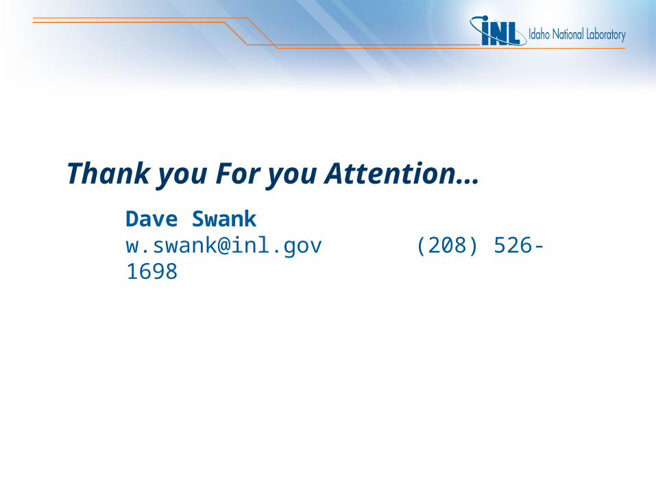
Specimen Size Effects in the Determination of Nuclear Grade Graphite Thermal Diffusivity
ASTM D02F000 Symposium on Graphite Testing for Nuclear Applications: the Significance of Test Specimen Volume and Geometry and the Statistical Significance of Test Specimen Population
September 19-20, 2013 Seattle Hilton; Seattle, WA
Dave SwankWill Windes
0
10
20
30
40
50
60
70
80
0 200 400 600 800 1000 1200
Temperature (°C)
Ther
mal
Diff
usiv
ity (m
m^2
/sec
)
AXM-5Q-06
AXM-5Q-07
AXM-5Q-08
AXM-5Q-08
AXM-5Q-08
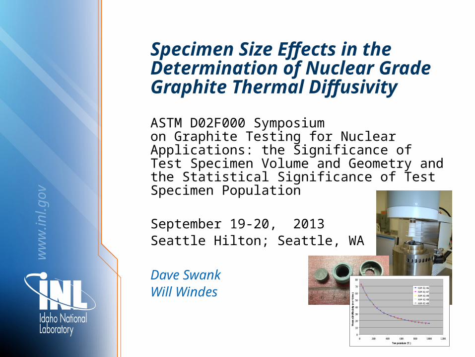
Outline:
• Description of measurement technique
• Sources of Uncertainty
– Limitations of heat loss correction models
– Limitations of finite laser pulse corrections
• Example of estimating measurement uncertainty
• Summarize and conclude
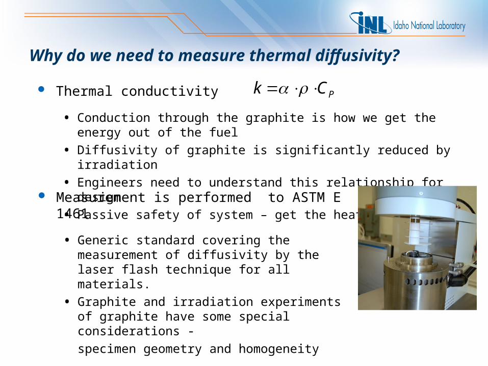
Why do we need to measure thermal diffusivity?
Thermal conductivity
• Conduction through the graphite is how we get the energy out of the fuel
• Diffusivity of graphite is significantly reduced by irradiation
• Engineers need to understand this relationship for design
• Passive safety of system – get the heat out
PCk
Measurement is performed to ASTM E 1461
• Generic standard covering the measurement of diffusivity by the laser flash technique for all materials.
• Graphite and irradiation experiments of graphite have some special considerations -
specimen geometry and homogeneity
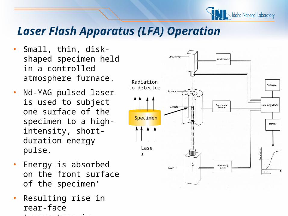
Laser Flash Apparatus (LFA) Operation
Radiation to detector
Laser
Specimen
• Small, thin, disk-shaped specimen held in a controlled atmosphere furnace.
• Nd-YAG pulsed laser is used to subject one surface of the specimen to a high-intensity, short-duration energy pulse.
• Energy is absorbed on the front surface of the specimen’
• Resulting rise in rear-face temperature is recorded with a sensitive IR detector.
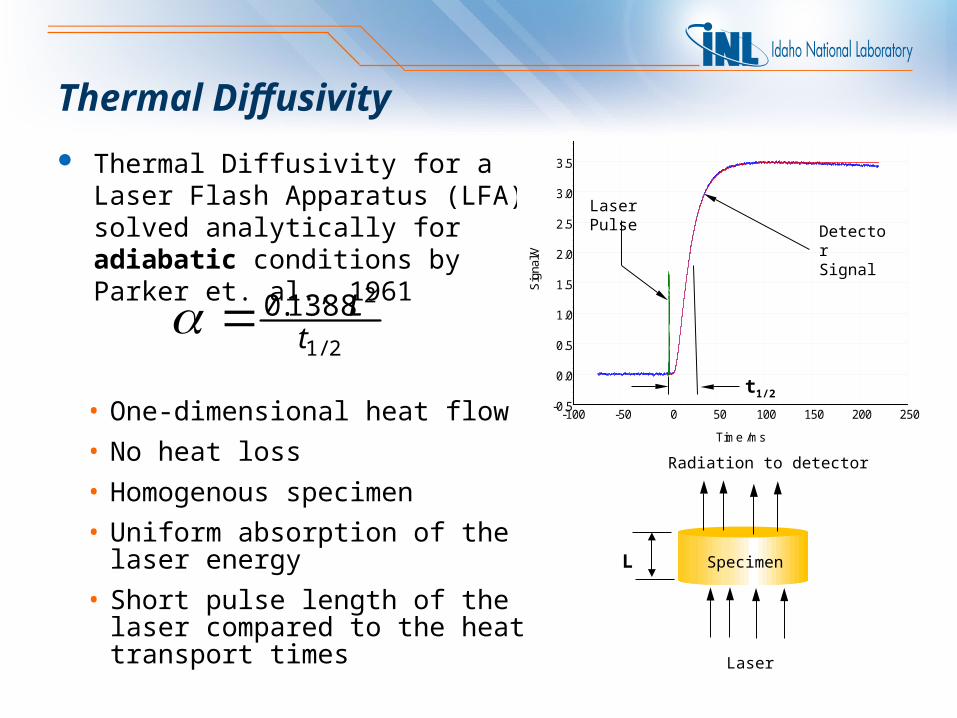
Thermal Diffusivity
• One-dimensional heat flow
• No heat loss
• Homogenous specimen
• Uniform absorption of the laser energy
• Short pulse length of the laser compared to the heat transport times
Thermal Diffusivity for a Laser Flash Apparatus (LFA) solved analytically for adiabatic conditions by Parker et. al., 1961
2/1
21388.0t
L
Radiation to detector
Laser
SpecimenL
-100 -50 0 50 100 150 200 250
Time /ms
-0.5
0.0
0.5
1.0
1.5
2.0
2.5
3.0
3.5
4.0
Sig
nal/V
Detector Signal
Laser Pulse
t1/2
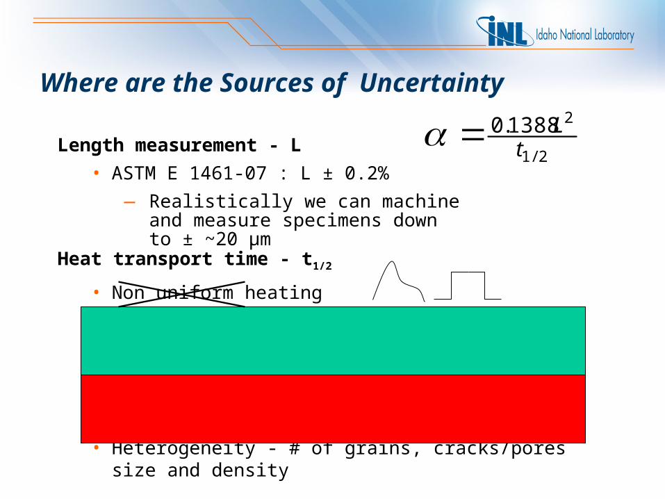
Heat transport time - t1/2
• Non uniform heating
• Multi directional conduction
• Heat Loss: Radiation, Conduction, Convection
• Finite laser pulse width
• Heterogeneity - # of grains, cracks/pores size and density
2/1
21388.0t
LWhere are the Sources of Uncertainty
Length measurement - L
• ASTM E 1461-07 : L ± 0.2%
— Realistically we can machine and measure specimens down to ± ~20 µm
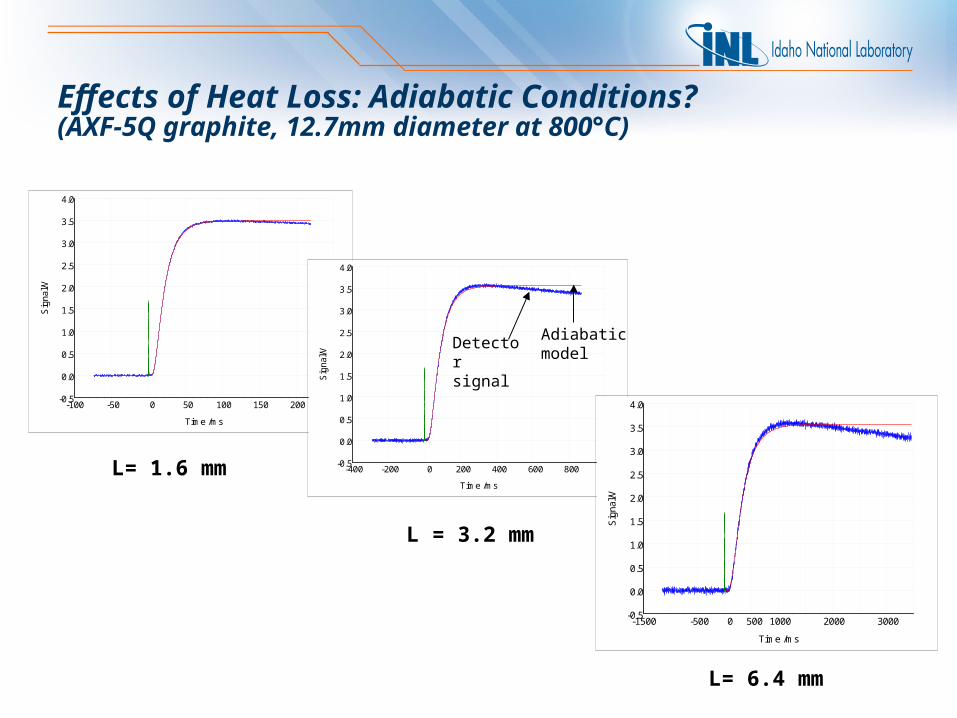
L= 1.6 mm
-100 -50 0 50 100 150 200 250
Time /ms
-0.5
0.0
0.5
1.0
1.5
2.0
2.5
3.0
3.5
4.0
Sig
nal/V
L = 3.2 mm
L= 6.4 mm
Effects of Heat Loss: Adiabatic Conditions? (AXF-5Q graphite, 12.7mm diameter at 800°C)
-400 -200 0 200 400 600 800 1000
Time /ms
-0.5
0.0
0.5
1.0
1.5
2.0
2.5
3.0
3.5
4.0
Sig
na
l/V
Detector signal
Adiabatic model
-1500 -500 0 500 1000 2000 3000
Time /ms
-0.5
0.0
0.5
1.0
1.5
2.0
2.5
3.0
3.5
4.0
Sig
nal/V
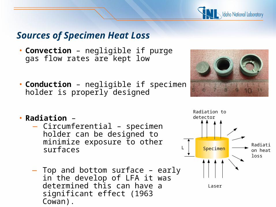
Sources of Specimen Heat Loss
• Convection – negligible if purge gas flow rates are kept low
• Conduction – negligible if specimen holder is properly designed
• Radiation –
— Top and bottom surface – early in the develop of LFA it was determined this can have a significant effect (1963 Cowan).
— Circumferential – specimen holder can be designed to minimize exposure to other surfaces
Radiation to detector
Radiation heat loss
Laser
SpecimenL
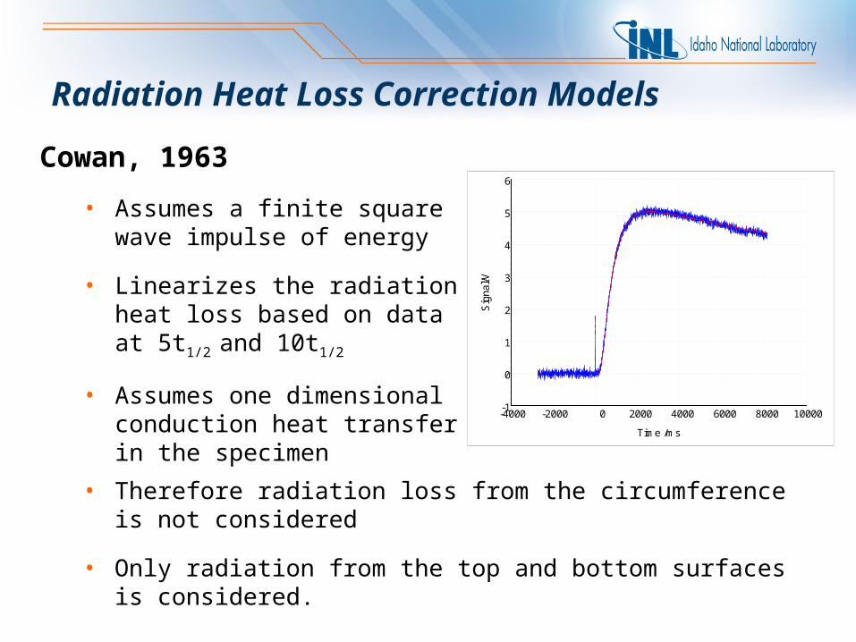
Radiation Heat Loss Correction Models
Cowan, 1963
• Assumes a finite square wave impulse of energy
• Linearizes the radiation heat loss based on data at 5t1/2 and 10t1/2
• Assumes one dimensional conduction heat transfer in the specimen
-4000 -2000 0 2000 4000 6000 8000 10000
Time /ms
-1
0
1
2
3
4
5
6
Sig
nal/V
• Therefore radiation loss from the circumference is not considered
• Only radiation from the top and bottom surfaces is considered.
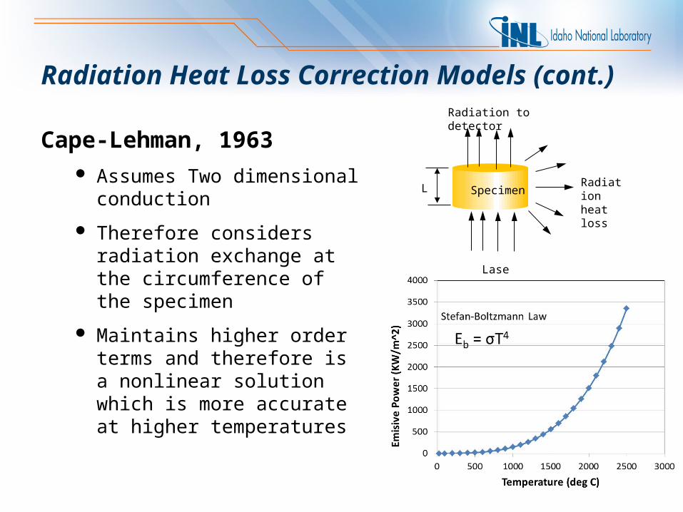
Cape-Lehman, 1963 Assumes Two dimensional
conduction
Therefore considers radiation exchange at the circumference of the specimen
Maintains higher order terms and therefore is a nonlinear solution which is more accurate at higher temperatures
Radiation to detector
Radiation heat loss
Laser
SpecimenL
Radiation Heat Loss Correction Models (cont.)
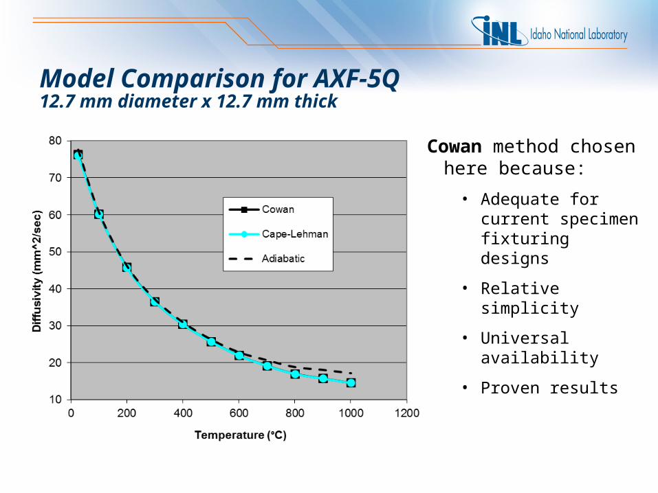
Model Comparison for AXF-5Q 12.7 mm diameter x 12.7 mm thick
Cowan method chosen here because:
• Adequate for current specimen fixturing designs
• Relative simplicity
• Universal availability
• Proven results
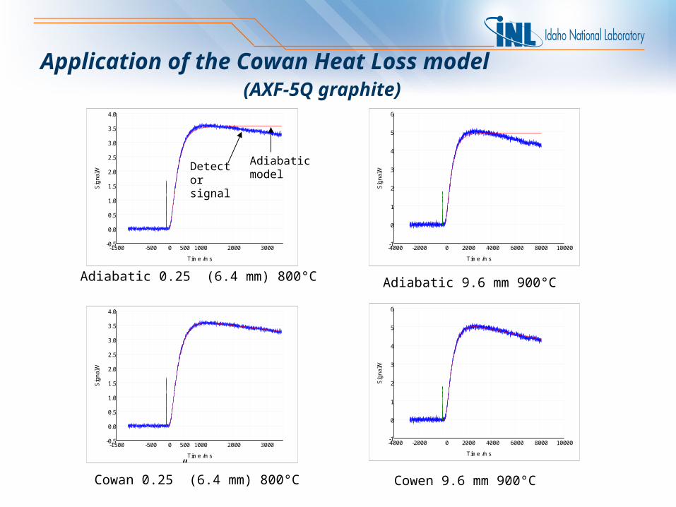
Application of the Cowan Heat Loss model (AXF-5Q graphite)
-1500 -500 0 500 1000 2000 3000
Time /ms
-0.5
0.0
0.5
1.0
1.5
2.0
2.5
3.0
3.5
4.0
Sig
nal/V
Cowan 0.25” (6.4 mm) 800°C
Adiabatic 0.25” (6.4 mm) 800°C
-4000 -2000 0 2000 4000 6000 8000 10000
Time /ms
-1
0
1
2
3
4
5
6
Sig
nal/V
-4000 -2000 0 2000 4000 6000 8000 10000
Time /ms
-1
0
1
2
3
4
5
6
Sig
nal/V
Cowen 9.6 mm 900°C
Adiabatic 9.6 mm 900°C
-1500 -500 0 500 1000 2000 3000
Time /ms
-0.5
0.0
0.5
1.0
1.5
2.0
2.5
3.0
3.5
4.0
Sig
nal/V
Detector signal
Adiabatic model
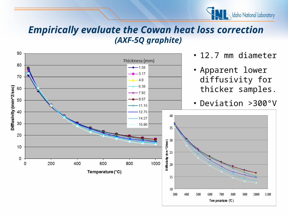
Empirically evaluate the Cowan heat loss correction (AXF-5Q graphite)
10
15
20
25
30
35
40
300 400 500 600 700 800 900 1000 1100
Temperature (°C)
Diff
usiv
ity (m
m^2
/sec
)
• 12.7 mm diameter
• Apparent lower diffusivity for thicker samples.
• Deviation >300°V
0
20
40
60
80
100
120
140
160
0 200 400 600 800 1000 1200
Temperature (°C)
Em
issi
ve P
ow
er (
kW/m
^2)
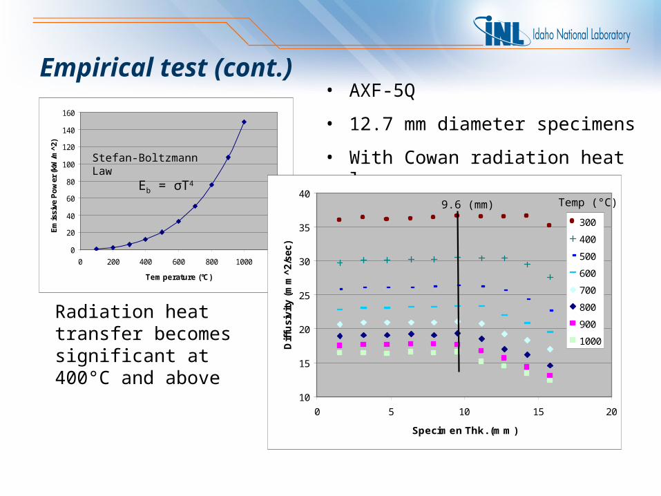
Stefan-Boltzmann Law Eb = σT4
• AXF-5Q
• 12.7 mm diameter specimens
• With Cowan radiation heat loss
Radiation heat transfer becomes significant at 400°C and above
Empirical test (cont.)
10
15
20
25
30
35
40
0 5 10 15 20
Specimen Thk. (mm)
Dif
fusiv
ity
(mm
^2/s
ec)
300
400
500
600
700
800
900
1000
9.6 (mm) Temp (°C)
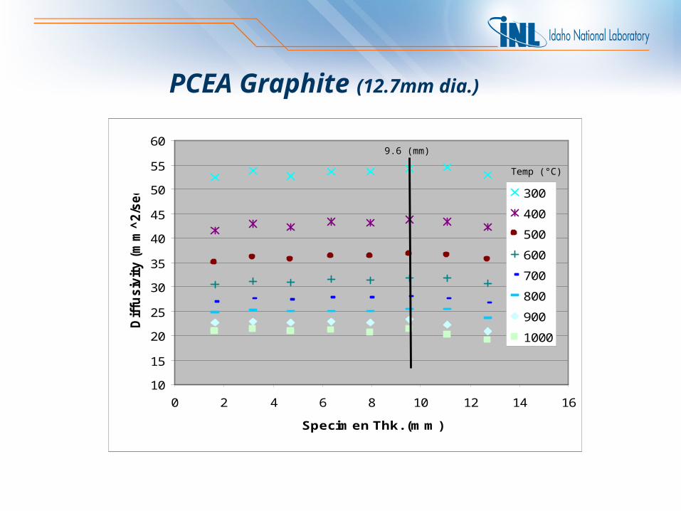
10
15
20
25
30
35
40
45
50
55
60
0 2 4 6 8 10 12 14 16
Specimen Thk. (mm)
Dif
fusiv
ity (
mm
^2/s
ec)
300
400
500
600
700
800
900
1000
9.6 (mm)
Temp (°C)
PCEA Graphite (12.7mm dia.)
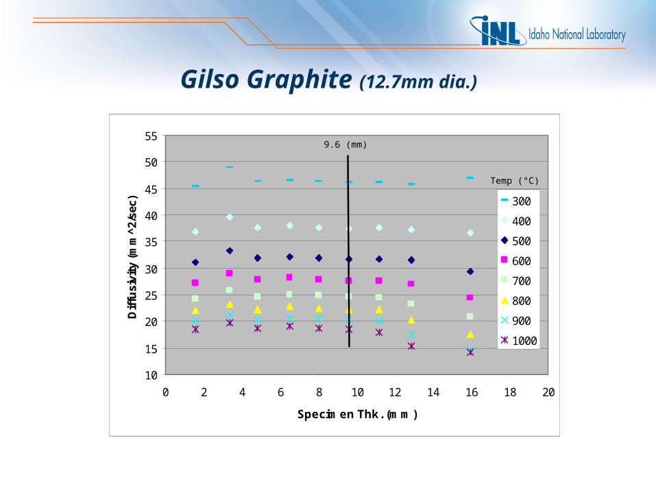
10
15
20
25
30
35
40
45
50
55
0 2 4 6 8 10 12 14 16 18 20
Specimen Thk. (mm)
Dif
fusi
vity
(m
m^2
/sec
) 300
400
500
600
700
800
900
1000
9.6 (mm)
Temp (°C)
Gilso Graphite (12.7mm dia.)
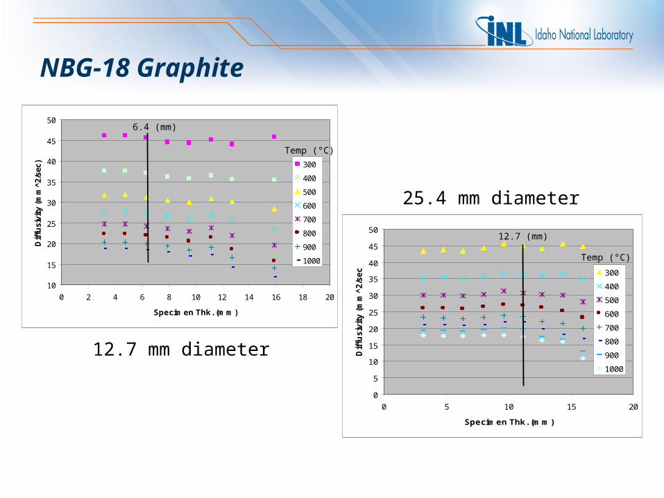
10
15
20
25
30
35
40
45
50
0 2 4 6 8 10 12 14 16 18 20
Specimen Thk. (mm)
Dif
fusi
vity
(m
m^2
/sec
) 300
400
500
600
700
800
900
1000
6.4 (mm)
Temp (°C)
0
5
10
15
20
25
30
35
40
45
50
0 5 10 15 20
Specimen Thk. (mm)
Dif
fusiv
ity (
mm
^2/s
ec)
300
400
500
600
700
800
900
1000
12.7 (mm)
Temp (°C)
NBG-18 Graphite
12.7 mm diameter
25.4 mm diameter
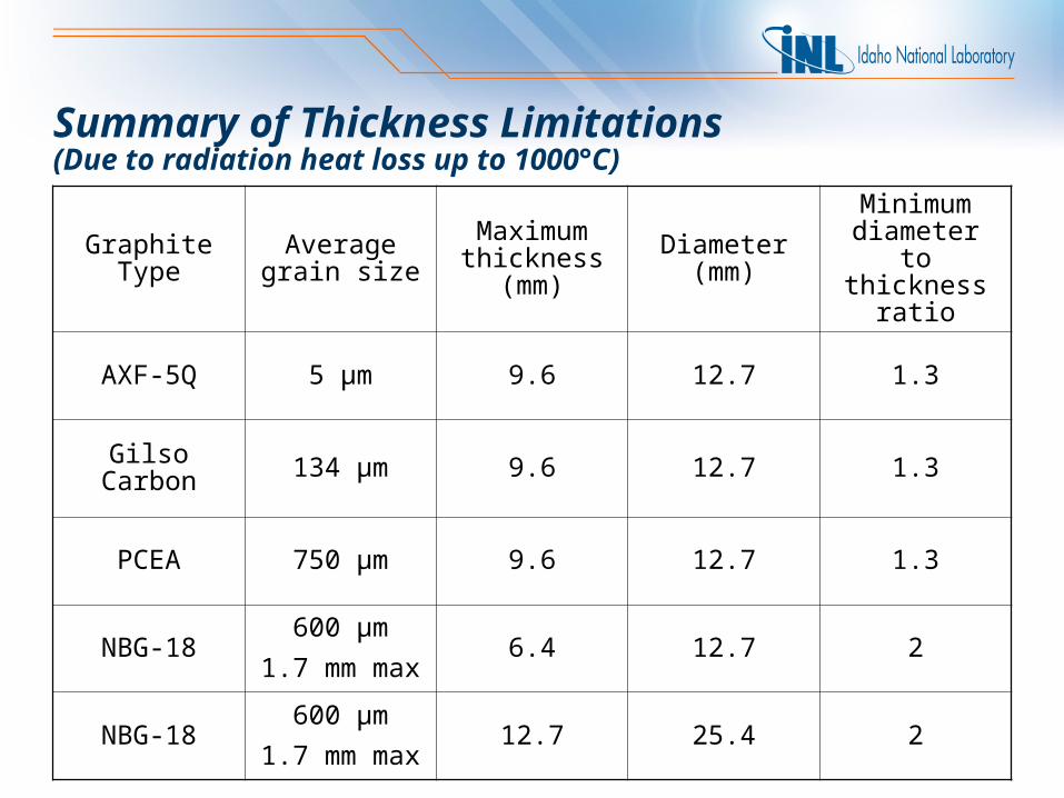
Summary of Thickness Limitations(Due to radiation heat loss up to 1000°C)
Graphite Type Average grain size
Maximum thickness
(mm)
Diameter (mm)
Minimum diameter to
thickness ratio
AXF-5Q 5 µm 9.6 12.7 1.3
Gilso Carbon 134 µm 9.6 12.7 1.3
PCEA 750 µm 9.6 12.7 1.3
NBG-18600 µm
1.7 mm max6.4 12.7 2
NBG-18600 µm
1.7 mm max12.7 25.4 2
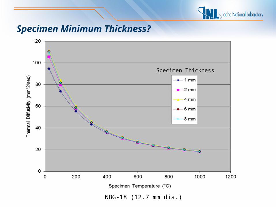
Specimen Minimum Thickness?
NBG-18 (12.7 mm dia.)
Specimen Thickness
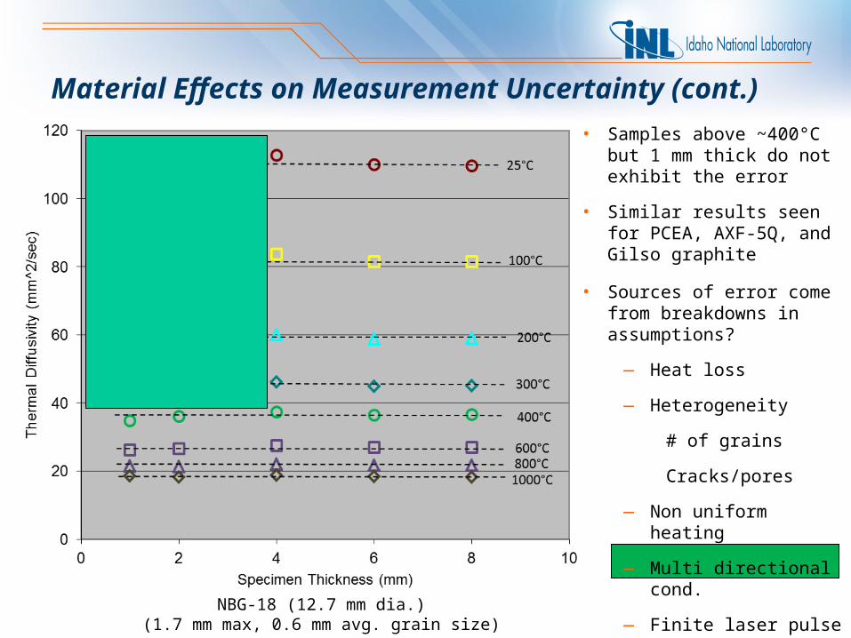
Material Effects on Measurement Uncertainty (cont.)
20%
• Samples above ~400°C but 1 mm thick do not exhibit the error
• Similar results seen for PCEA, AXF-5Q, and Gilso graphite
NBG-18 (12.7 mm dia.)(1.7 mm max, 0.6 mm avg. grain size)
• Sources of error come from breakdowns in assumptions?
— Heat loss
— Heterogeneity
# of grains
Cracks/pores
— Non uniform heating
— Multi directional cond.
— Finite laser pulse width
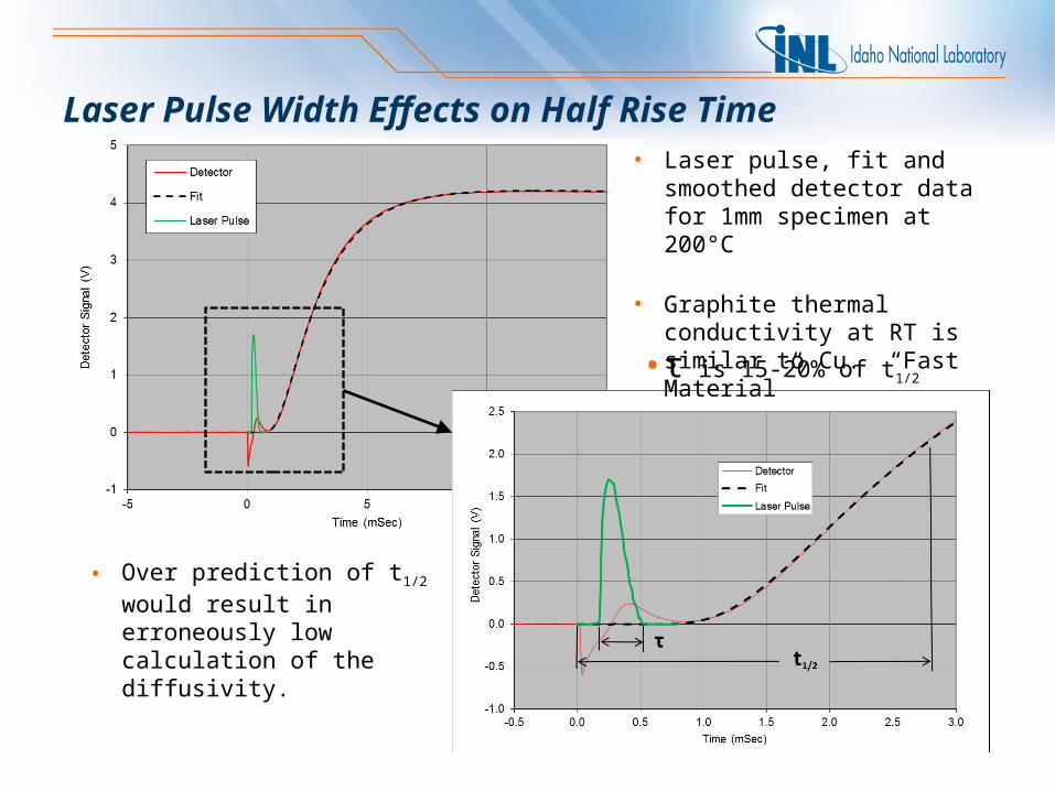
Laser Pulse Width Effects on Half Rise Time• Laser pulse, fit and smoothed
detector data for 1mm specimen at 200°C
• Graphite thermal conductivity at RT is similar to Cu. “Fast Material”
• Over prediction of t1/2 would result in erroneously low calculation of the diffusivity.
•τ is 15-20% of t1/2
6%
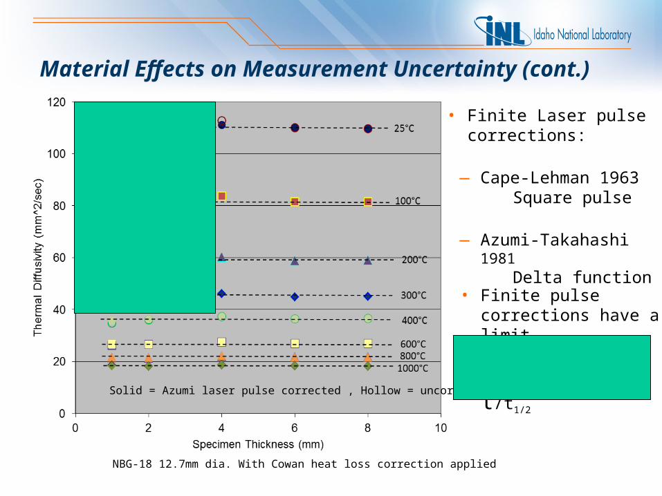
Material Effects on Measurement Uncertainty (cont.)
Solid = Azumi laser pulse corrected , Hollow = uncorrected
• Finite Laser pulse corrections:
— Cape-Lehman 1963Square pulse
— Azumi-Takahashi 1981Delta function
NBG-18 12.7mm dia. With Cowan heat loss correction applied
• Finite pulse corrections have a limit
• Establish a more
generic limit for τ/t1/2
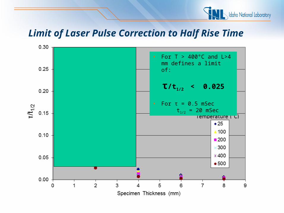
Limit of Laser Pulse Correction to Half Rise Time
• For T > 400°C and L>4 mm defines a limit of:
τ/t1/2 < 0.025
• For τ = 0.5 mSec t1/2 = 20 mSec
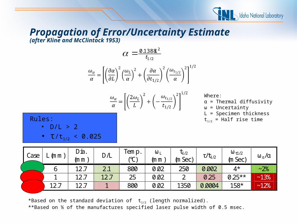
Propagation of Error/Uncertainty Estimate(after Kline and McClintock 1953)
2/1
21388.0t
L
Where:α = Thermal diffusivityω = UncertaintyL = Specimen thicknesst1/2 = Half rise time
*Based on the standard deviation of t1/2 (length normalized).**Based on ½ of the manufactures specified laser pulse width of 0.5 msec.
Rules:• D/L > 2
• τ/t1/2 < 0.025
Case L (mm) Dia. (mm) D/L Temp.
(°C) ωL
(mm) t1/2
(mSec) τ/t1/2 ωt1/2
(mSec) ωα/α
A 6 12.7 2.1 800 0.02 250 0.002 4* ~2% B 1 12.7 12.7 25 0.02 2 0.25 0.25** ~13% C 12.7 12.7 1 800 0.02 1350 0.0004 158* ~12%
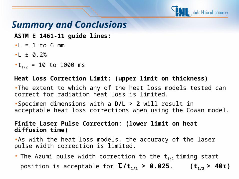
Summary and ConclusionsASTM E 1461-11 guide lines:
•L = 1 to 6 mm
•L ± 0.2%
•t1/2 = 10 to 1000 ms
Heat Loss Correction Limit: (upper limit on thickness)
•The extent to which any of the heat loss models tested can correct for radiation heat loss is limited.
•Specimen dimensions with a D/L > 2 will result in acceptable heat loss corrections when using the Cowan model.
Finite Laser Pulse Correction: (lower limit on heat diffusion time)
•As with the heat loss models, the accuracy of the laser pulse width correction is limited.
• The Azumi pulse width correction to the t1/2 timing start position is acceptable for
τ/t1/2 > 0.025. (t1/2 > 40τ)
Summary and Conclusions (cont.)
Comment on representing the bulk material:
•The thermal diffusivity remained unchanged for specimens of PCEA and NBG-18 down to 1 mm thick when the condition of τ/t1/2 > 0.025 was met (T>400°C). This indicates that the homogeneity of these relatively large grained graphite's is sufficient down to 1mm thick for LFA determination of diffusivity.