
radiation shielding design 2010 radiation shielding design 2010
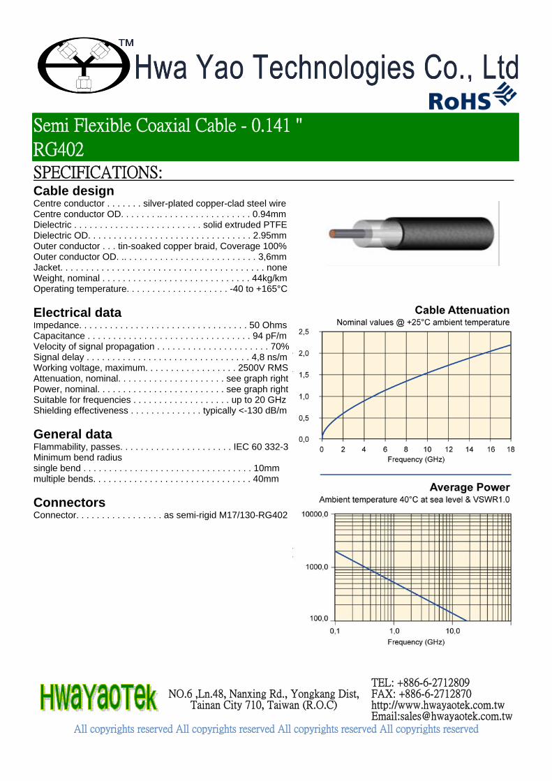
SPECIFICATIONS: Cable design Centre conductor . . . . . . . silver-plated copper-clad steel wire Centre conductor OD. . . . . . . .. . . . . . . . . . . . . . . . . . 0.94mm Dielectric . . . . . . . . . . . . . . . . . . . . . . . . . solid extruded PTFE Dielectric OD. . . . . . . . . . . . . . . . . . . . . . . . . . . . . . . . 2.95mm Outer conductor . . . tin-soaked copper braid, Coverage 100% Outer conductor OD. .. . . . . . . . . . . . . . . . . . . . . . . . . . 3,6mm Jacket. . . . . . . . . . . . . . . . . . . . . . . . . . . . . . . . . . . . . . . . none Weight, nominal . . . . . . . . . . . . . . . . . . . . . . . . . . . . . 44kg/km Operating temperature. . . . . . . . . . . . . . . . . . . . -40 to +165°C
Electrical data Impedance. . . . . . . . . . . . . . . . . . . . . . . . . . . . . . . . . 50 Ohms Capacitance . . . . . . . . . . . . . . . . . . . . . . . . . . . . . . . . 94 pF/m Velocity of signal propagation . . . . . . . . . . . . . . . . . . . . . . 70% Signal delay . . . . . . . . . . . . . . . . . . . . . . . . . . . . . . . . 4,8 ns/m Working voltage, maximum. . . . . . . . . . . . . . . . . . 2500V RMS Attenuation, nominal. . . . . . . . . . . . . . . . . . . . . see graph right Power, nominal. . . . . . . . . . . . . . . . . . . . . . . . . see graph right Suitable for frequencies . . . . . . . . . . . . . . . . . . . up to 20 GHz Shielding effectiveness . . . . . . . . . . . . . . typically <-130 dB/m
General data Flammability, passes. . . . . . . . . . . . . . . . . . . . . . IEC 60 332-3 Minimum bend radius single bend . . . . . . . . . . . . . . . . . . . . . . . . . . . . . . . . . 10mm multiple bends. . . . . . . . . . . . . . . . . . . . . . . . . . . . . . . 40mm
Connectors Connector. . . . . . . . . . . . . . . . . as semi-rigid M17/130-RG402
Semi Flexible Coaxial Cable - 0.141 ''
RG402
NO.6 ,Ln.48, Nanxing Rd., Yongkang Dist,
Tainan City 710, Taiwan (R.O.C)
TEL: +886-6-2712809 FAX: +886-6-2712870 http://www.hwayaotek.com.tw Email:[email protected]
All copyrights reserved All copyrights reserved All copyrights reserved All copyrights reserved
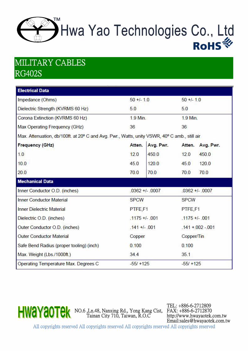
MILITARY CABLES
RG402S
NO.6 ,Ln.48, Nanxing Rd., Yong Kang Cist,
Tainan City 710, Taiwan, R.O.C
TEL: +886-6-2712809 FAX: +886-6-2712870 http://www.hwayaotek.com.tw Email:[email protected]
All copyrights reserved All copyrights reserved All copyrights reserved All copyrights reserved


SPECIFICATIONS:
Harbour SFL402&405 CABLE
SFL402&405
NO.6 ,Ln.48, Nanxing Rd., Yongkang Dist,
Tainan City 710, Taiwan (R.O.C)
TEL: +886-6-2712809 FAX: +886-6-2712870 http://www.hwayaotek.com.tw Email:[email protected]
All copyrights reserved All copyrights reserved All copyrights reserved All copyrights reserved

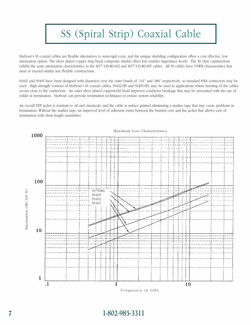
Harbour’s SS coaxial cables are flexible alternatives to semi-rigid coax, and the unique shielding configuration offers a cost effective, lowattenuation option. The silver plated copper strip/braid composite shields effect low transfer impedance levels. The 50 ohm constructionsexhibit the same attenuation characteristics as the M17/130-RG402 and M17/133-RG405 cables. All SS cables have VSWR characteristics thatmeet or exceed similar size flexible constructions.
SS402 and SS405 have been designed with diameters over the outer braids of .141” and .086” respectively, so standard SMA connectors may beused. High strength versions of Harbour’s SS coaxial cables, SS402-HS and SS405-HS, may be used in applications where bending of the cablesoccurs close to the connectors. An outer silver plated copperweld braid improves conductor breakage that may be associated with the use ofsolder in termination. Harbour can provide termination techniques to ensure system reliability.
An overall FEP jacket is resistant to oil and chemicals, and the cable is surface printed eliminating a marker tape that may cause problems intermination. Without the marker tape, an improved level of adhesion exists between the braided core and the jacket that allows ease oftermination with short length assemblies.
7 1-802-985-3311
SS (Spiral Strip) Coaxial Cable
F requency i n GHz
Maximum Loss Characteristics
SS75086SS405SS402SS401
Att
enuat
ion (
db/1
00 f
t)

1-802-985-3311 8HarbourI N D U S T R I E S
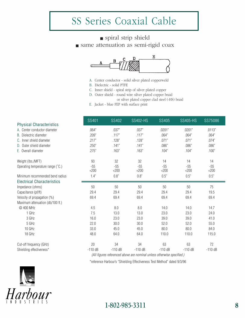
SS Series Coaxial Cablen spiral strip shield
n same attenuation as semi-rigid coax
A. Center conductor - solid silver plated copperweldB. Dielectric - solid PTFEC. Inner shield - spiral strip of silver plated copperD. Outer shield - round wire silver plated copper braid
or silver plated copper clad steel (-HS) braidE. Jacket - blue FEP with surface print
SS401 SS402 SS402-HS SS405 SS405-HS SS75086Physical CharacteristicsA. Center conductor diameter .064” .037” .037” .0201” .0201” .0113”B. Dielectric diameter .209” .117” .117” .064” .064” .064”C. Inner shield diameter .217” .128” .128” .071” .071” .074”D. Outer shield diameter .250” .141” .141” .086” .086” .086”E. Overall diameter .275” .163” .163” .104” .104” .100”
Weight (lbs./MFT) 93 32 32 14 14 14Operating temperature range (˚C.) -55 -55 -55 -55 -55 -55
+200 +200 +200 +200 +200 +200Minimum recommended bend radius 1.4” 0.8” 0.8” 0.5” 0.5” 0.5”Electrical CharacteristicsImpedance (ohms) 50 50 50 50 50 75Capacitance (pf/ft) 29.4 29.4 29.4 29.4 29.4 19.5Velocity of propagation (%) 69.4 69.4 69.4 69.4 69.4 69.4Maximum attenuation (db/100 ft.)
@ 400 MHz 4.5 8.0 8.0 14.0 14.0 14.71 GHz 7.5 13.0 13.0 23.0 23.0 24.03 GHz 16.0 23.0 23.0 39.0 39.0 41.05 GHz 22.0 30.0 30.0 52.0 52.0 55.0
10 GHz 33.0 45.0 45.0 80.0 80.0 84.018 GHz 48.0 64.0 64.0 110.0 110.0 115.0
Cut-off frequency (GHz) 20 34 34 63 63 72Shielding effectiveness* -110 dB -110 dB -110 dB -110 dB -110 dB -110 dB
(All figures referenced above are nominal unless otherwise specified.)
*reference Harbour’s “Shielding Effectiveness Test Method” dated 9/3/96
Harbour’s SS coaxial cables are flexible alternatives to semi-rigid coax, and the unique shielding configuration offers a cost effective, lowattenuation option. The silver plated copper strip/braid composite shields effect low transfer impedance levels. The 50 ohm constructionsexhibit the same attenuation characteristics as the M17/130-RG402 and M17/133-RG405 cables. All SS cables have VSWR characteristics thatmeet or exceed similar size flexible constructions.
SS402 and SS405 have been designed with diameters over the outer braids of .141” and .086” respectively, so standard SMA connectors may beused. High strength versions of Harbour’s SS coaxial cables, SS402-HS and SS405-HS, may be used in applications where bending of the cablesoccurs close to the connectors. An outer silver plated copperweld braid improves conductor breakage that may be associated with the use ofsolder in termination. Harbour can provide termination techniques to ensure system reliability.
An overall FEP jacket is resistant to oil and chemicals, and the cable is surface printed eliminating a marker tape that may cause problems intermination. Without the marker tape, an improved level of adhesion exists between the braided core and the jacket that allows ease oftermination with short length assemblies.
7 1-802-985-3311
SS (Spiral Strip) Coaxial Cable
F requency i n GHz
Maximum Loss Characteristics
SS75086SS405SS402SS401
Att
enuat
ion (
db/1
00 f
t)
1-802-985-3311 8HarbourI N D U S T R I E S
SS Series Coaxial Cablen spiral strip shield
n same attenuation as semi-rigid coax
A. Center conductor - solid silver plated copperweldB. Dielectric - solid PTFEC. Inner shield - spiral strip of silver plated copperD. Outer shield - round wire silver plated copper braid
or silver plated copper clad steel (-HS) braidE. Jacket - blue FEP with surface print
SS401 SS402 SS402-HS SS405 SS405-HS SS75086Physical CharacteristicsA. Center conductor diameter .064” .037” .037” .0201” .0201” .0113”B. Dielectric diameter .209” .117” .117” .064” .064” .064”C. Inner shield diameter .217” .128” .128” .071” .071” .074”D. Outer shield diameter .250” .141” .141” .086” .086” .086”E. Overall diameter .275” .163” .163” .104” .104” .100”
Weight (lbs./MFT) 93 32 32 14 14 14Operating temperature range (˚C.) -55 -55 -55 -55 -55 -55
+200 +200 +200 +200 +200 +200Minimum recommended bend radius 1.4” 0.8” 0.8” 0.5” 0.5” 0.5”Electrical CharacteristicsImpedance (ohms) 50 50 50 50 50 75Capacitance (pf/ft) 29.4 29.4 29.4 29.4 29.4 19.5Velocity of propagation (%) 69.4 69.4 69.4 69.4 69.4 69.4Maximum attenuation (db/100 ft.)
@ 400 MHz 4.5 8.0 8.0 14.0 14.0 14.71 GHz 7.5 13.0 13.0 23.0 23.0 24.03 GHz 16.0 23.0 23.0 39.0 39.0 41.05 GHz 22.0 30.0 30.0 52.0 52.0 55.0
10 GHz 33.0 45.0 45.0 80.0 80.0 84.018 GHz 48.0 64.0 64.0 110.0 110.0 115.0
Cut-off frequency (GHz) 20 34 34 63 63 72Shielding effectiveness* -110 dB -110 dB -110 dB -110 dB -110 dB -110 dB
(All figures referenced above are nominal unless otherwise specified.)
*reference Harbour’s “Shielding Effectiveness Test Method” dated 9/3/96