Specifications - Mr. Crane€¦ · · 2013-09-18Rear - Planetary type; bogie mounted tridem...
84
-1- General dimensions feet meters Overall width, outriggers extended, (over floats) 27’ 4" 8.33 Overall width, outriggers extended, (c/l of jacks) 24’ 6" 7.46 Overall width, outriggers retracted, jacks removed 11’ 10" 3.61 Vehicle clearance circle over outside of front bumper 122’ 10" 37.44 Vehicle clearance circle over outside of front bumper counterweight 125’ 10" 38.35 Minimum ground clearance (at bottom of front bogie beams) 8-7/8" 0.22 Counterweight tailswing (at corners) 18’ 9" 5.72 Overall cab width (upper) 11’ 10" 3.61 Radius of boom hinge pin 3’ 2" 0.97 Height of boom hinge pin 7’ 3-3/8" 2.22 Ground clearance under counterweight 5’ 5-3/8" 1.65 Litho in U.S.A. 3/97 #5237 Specifications (HYLAB) Hydraulic Lattice Boom Truck Crane HC-278H 300-ton (272 metric ton) Not to Scale
-
Upload
nguyendiep -
Category
Documents
-
view
220 -
download
1
Transcript of Specifications - Mr. Crane€¦ · · 2013-09-18Rear - Planetary type; bogie mounted tridem...

- 1 -
General dimensions feet meters
Overall width, outriggers extended, (over floats) 27' 4" 8.33
Overall width, outriggers extended, (c/l of jacks) 24' 6" 7.46
Overall width, outriggers retracted,
jacks removed 11' 10" 3.61
Vehicle clearance circle over outside of
front bumper 122' 10" 37.44
Vehicle clearance circle over outside of front
bumper counterweight 125' 10" 38.35
Minimum ground clearance
(at bottom of front bogie beams) 8-7/8" 0.22
Counterweight tailswing (at corners) 18' 9" 5.72
Overall cab width (upper) 11' 10" 3.61
Radius of boom hinge pin 3' 2" 0.97
Height of boom hinge pin 7' 3-3/8" 2.22
Ground clearance under counterweight 5' 5-3/8" 1.65
Litho in U.S.A. 3/97 #5237
Specifications(HYLAB) Hydraulic Lattice Boom Truck Crane
HC-278H 300-ton (272 metric ton)
Not to Scale

- 2 -
General Dimensions - Open Throat Boom feet meters
Basic Boom Length 60' 18.29Overall length: boom in travel position over rear of carrier, with �A� upper and no bumper - -counterweights - - -
With 60' (18.29 m) basic boom - open throat 96' 4-1/2" 1 29.38 1
Height: over boom live mast with boom in travel position - - -With 60' (18.29 m) basic boom - open throat 21' 9-3/4" 6.65
General Dimensions - Hammerhead Boom feet meters
Basic Boom Length 45' 13.71Overall length: boom in travel position over rear of carrier, with �A� upper and �A� bumpercounterweights only -
With 45' (13.71 m) basic hammerhead boom - 79' 10-/14" 1 24.34 1
Height: over boom live mast with boom in travel position over rear of carrier - - -With 45' (13.71 m) basic hammerhead boom 23' 5" 2 7.14 2
1 Interference with carrier cab prohibits over-the-road travel with boom horizontal over front of carrier.2 Special boom carrying links (for hammerhead boom only) reduce over-all height to 12' 11-1/2" (3.95 m).
Total
Revolving Upperstructure Only Ibs. kg
Basic crane upper with Cummins N14 - C360 diesel engine, boomhoist rope, boom stops, - - boom live mast, bail assembly, full fuel and self undecking equipment 71,440 32 405
Add 810' (247 m) of 1" (25 mm) Type �P� wire rope on rear drum 1,475 669
Add 1,025' (312 m) of 1-1/8" (29 mm) Type �LB� wire rope on front drum 2,400 1 089
75,315 34 163
Add 30' (9.14 m) open throat boom base section 4,125 1 871
Total 79,440 36 034
Travel Weights - approximate
Front tridem axle Rear tridem axle Total
Carrier Only Ibs. kg Ibs. kg Ibs. kg
Carrier with Detroit Diesel Series 60 engine and - - - - - -with revolving upperstructure removed 33,020 14 978 63,740 28 912 96,760 43 890
Remove front outrigger jacks -1,350 -612 -850 -386 -2,200 -998
Remove rear outrigger jacks + 890 + 404 -3,090 -1 402 -2,200 -998
Remove 5 outrigger floats from carrier storage. -340 -154 -400 -181 -740 -335
Goodyear tires -600 -272 -1,200 -544 -1,800 -816
Total 31,620 14 343 58,200 26 400 89,820 40 743

- 3 -
Axle Loads - Approximate
Basic MachineGross Weight Upper facing front Upper facing rear
** Ibs. kg Ibs. kg Ibs. kg Ibs. kg Ibs. kg
A 93,330 42 335 -25,666 -11 642 118,996 53 977 48,220 21 873 45,110 20 462B 70,500 31 979 30,020 13 617 40,480 18 362 30,020 13 617 40,480 18 362C 163,830 74 314 4,354 1 975 159,476 72 339 78,240 35 490 85,590 38 824
Component Weights Front axle Rear axle Front axle Rear axle
Ibs. kg Ibs. kg Ibs. kg Ibs. kg Ibs. kg
Upperstructure -Remove self undecking equipment from upper -13,910 -6 310 -695 -315 -13,215 -5 994 -2,200 -998 -11,710 -5 312Remove counterweight �A� -30,000 -13 608 18,625 8 448 -48,625 -22 056 -24,870 -11 281 -5,130 -2 327Rear drum wire rope - 810' (247 m) of - - - - - - - - - -
1" (25 mm) Type �P� 1,475 669 -125 -57 1,600 726 430 195 1,045 474Front drum wire rope - 1,025' (312 m) of - - - - - - - - - -
1-1/8" (29 mm) Type �LB� 2,400 1 089 145 66 2,255 1 023 355 161 2,045 928Boomhoist wire rope on drum - 870' (265 m) - - - - - - - - - -
of 1" (25 mm) Type �W� 1,620 735 -335 -152 1,955 887 675 306 945 429Boom stops, support struts and lever arms -1,365 -619 285 129 -1,650 -748 -570 -259 -795 -360
Carrier -Add front outrigger box 10,560 4 790 6,490 2 944 4,070 1 846 6,490 2 944 4,070 1 846Add rear outrigger box 10,560 4 790 -4,290 -1 946 14,850 6 736 -4,290 -1 946 14,850 6 736Add front outrigger jacks 2,200 998 1,350 612 850 386 1,350 612 850 386Add rear outrigger jacks 2,200 998 -890 -404 3,090 1 402 -890 -404 3,090 1 402Add main outrigger floats 660 299 309 140 351 159 309 140 351 159Add bumper outrigger float 80 36 31 14 49 22 31 14 49 22Remove H/D axles -2,080 -943 0 0 -2,080 -943 0 0 -2,080 -943Add Ceemat transmission 300 136 300 136 0 0 300 136 0 0Add "A" bumper counterweight 11,400 5 171 15,570 7 063 -4,170 -1 892 15,570 7 063 -4,170 -1 892Add "B" bumper counterweight 15,300 6 940 21,591 9 794 -6,291 -2 854 21,591 9 794 -6,291 -2 854Add Goodyear tires -1,800 -816 -600 -272 -1,200 -544 -600 -272 -1,200 -544
Attachment -30' (9.14 m) open throat tubular boom base - - - - - - - - - -
section with 4 connecting pins - - - - - - - - - - -horizontal over rear of carrier. 4,125 1 871 - - - - -2,515 -1 141 6,640 3 012
35' (10.67 m) boom live mast and bridle - - - - - - - - - - -mast horizontal over rear of carrier. 6,490 2 944 7,235 3 282 -745 -338 -5,880 -2 667 12,370 5 671
Boomhoist wire rope (from bail to boom live - - - - - - - - - -mast) - mast horizontal over rear of carrier 1,620 735 1,070 485 550 250 -735 -333 2,355 1 068
60' (18.29 m) open throat tubular boom - - - - - - - - - - -horizontal over rear of carrier. 9,300 4 218 - - - - -13,985 -6 344 23,285 10 562
45' (13.72 m) hammerhead tubular boom - - - - - - - - - - -horizontal over rear of carrier. 9,860 4 472 - - - - -12,120 -5 498 21,980 9 970
** A - Upper B - Carrier C - Total
Standard HC-278H revolving upperstructureequipped with Cummins N14-C360 diesel engine,load hoist drums, 30,000 Ibs. (13 608 kg)counterweight �A�, self undecking equipmentmounted on 288" (7.32 m) wheelbase, 12 x 6 drivecarrier, 11' 10" (3.61 m) wide, equipped with DetroitDiesel 60 Series engine, front center hydraulic jack,Michelin tires, and full fuel.
Adjust axle loadings accordingly for thefollowing components:

- 4 -
Mountingn Type288" (7.32 m) wheelbase, 12 x 6 drive.11' 10" (3.61 m) wide.
Frame - Main members heat treated alloysteel, triple-box construction. Machinedmounting surface for outer race of turntablebearing. Towing shackles front and rear.
Turntable bearing - Outer race, with integralexternal tooth swing (ring) gear bolted tocarrier frame.
n OutriggersDual outriggers, with hydraulic beams andjacks, mounted at center and rear of carrier.Hydraulic outrigger beams and jack cylindersindividually controlled from valve at eachoutrigger beam location. Center outriggerbox equipped with rollers which ride in a trackto facilitate removal of outrigger assemblywhen required.
Outrigger box pin puller - hydraulic; standard.
Front center hydraulic jack with float -Single hydraulic jack, with float, mountedat front of the carrier. Jack setting controlledby valve at left front of carrier. Jack/floatassembly required for handling 360° swingrated capacities. Warning horn sounds ifground surface allows front center jack/floatto settle.
Floats - Four low profile, snap-on, alloy steel;34" (.86 m) dia. base.
Front center: snap-on aluminum; 24" (.61 m)dia. base.
n AxlesFront - Tubular; bogie mounted tridem axles,
single wheels, 115" (2.92 m) track.
Rear - Planetary type; bogie mountedtridem axles, dual wheels, 110.25"(2.80 m) track.
Suspension - Hendrickson bronze bushedequalizer beams with rubber bushed torquerods and shock absorbers on front axle.
Wheels and rims - Front; disc type. Rear;integral with planetary hubs.
n TiresSingle tires front, dual tires rear.
Standard - 14.00 x 24L (20-ply rating)transport type tread.
Optional - Michelin 14R24 XGC radials frontand rear.
n Bumper Counterweight�A� counterweight - 11,400 Ibs. (5 171 kg)
�B� counterweight - 15,300 Ibs. (6 940 kg)
n Carrier CabOne-man, fully enclosed. Air suspensionmounted bucket seat with seat belt. Noiseabsorbing insulation with vinyl covering,sound reduction headliner, rubber floor mat.Tilt-out instrument panel (for easy service)includes speedometer, odometer, tachom-eter, voltmeter, hourmeter, clock, and gaugesfor fuel level, engine temperature, engine oilpressure, air pressure, and transmissiontemperature (auto. trans. only). Controlswitches are included for cruise control,engine fan clutch, heater/defroster, andlights. Also included are low air pressurewarning buzzer/light, transmission overheatwarning buzzer/light (auto. trans only) andparking brake applied light. The tilt/telescop-ing steering column includes key lockingignition/starter, and 2-speed windshieldwiper/washer. Sliding right and rear windows.Roll down door window. Front and roof freshair vents.
Carriern Electrical System12-volt negative ground system with 12-volt starting. Includes dual sealed beamheadlights, directional signals with 4-wayflashing system, stop and tail lights, side turnindicators, clearance lights, horn, dome light,dimmer switch, and four 12-volt Group 31batteries.
n Fuel TankOne 85 gallon (321.7 liter) capacity aluminumtank; side mounted on carrier frame.
n Standard EquipmentWest Coast type rear view mirrors withadjustable convex mirror, lug wrench, 2-wayreading bubble levels on both sides of carrier.High pressure lube fittings at all bearingpoints, hand grab rails, fenders, mud flaps,skid-resistant finish on carrier deck, backupalarm, carrier deck access ladder both sidesand rear of carrier.
n BrakesAir brake system
Service - Dual circuit with modulatedemergency brakes. Bendix dual circuit12 wheel air brakes with service chambers on6 front wheels and spring applied, air releasedemergency, parking, service chambers on6 rear wheels. Air dryer standard.
Size -
Rear wheels; 16-1/2" x 7" (0.50 x 0.18 m)
Front wheels; 16-1/2" x 6" (0.50 x 0.15 m)
Steering - Sheppard full integral hydraulicpower with one master gear (includeshydraulic control valving), one slave gear(includes no valving) and one hydraulic pumpfor each axle. Steering gears mounted high onside of frame to minimize exposure tohazards. Separate master and slave for eachwheel eliminates transfer of steering forcefrom entire system into one axle which couldoverload and damage linkage. Steering wheelis mechanically connected to axles to allowsteering (with increased steering input effort)in the event of hydraulic system failure.Multiple pumps minimize possibility of totalhydraulic system failure and only requireincrease in steering input effort sufficient tocompensate for that portion of system thatfailed. High speed, high power system tomaximize maneuverability both on the jobsite and on the road.
n Engine/TransmissionsCarrier engine - 12.7 liter Series 60 DDECdiesel; with starter, full-pressure lubrication,power steering pump, dry-type air cleaner, aircompressor and alternator.
Clutch - Valeo 17" (.43 m) single plate, drydisc, diaphragm spring.
Transmissions -
Main - Eaton RTO 14908LL, ten speedsforward, three reverse.
Auxiliary - Spicer P-1241-C; 4-speed, midshipmounted.
Universals - Easy service half-round u-joints.
Automatic - Optional
Main - Eaton RTO 14109B ATE CEEMAT(Converter Enhanced Electronically ManagedAutomatic Transmission), 9 speeds forward,shifted fully automatically, 1 reverse. Ratiosand speeds are similar to the manualtransmission. Consult factory for more details.
Auxiliary - Spicer P-1241-D; 4-speed midshipmounting. Same as the auxiliary transmissionfor the manual version except with a 1.59:11st gear ratio.

- 5 -
Engine Specifications Detroit Diesel Series 60 DDEC
Number of cylinders 6Bore 5.12" (0.13 m)Stroke 6.30" (0.16 m)Piston Displacement 778 cu. in. (12 751 cm3)Max. brake h.p. @ r.p.m. 430 (321 kw) @ 2,100Governed load speed r.p.m. 2,100Peak torque @ r.p.m. 1,450 ft. Ibs. (1 966 joules) @ 1,200Electrical system 12-volt charging/12-volt startingBatteries Four 12-voltAir compressor Bendix TU-FLO 1400
Carrier SpeedsMain - Eaton RTO 14908LL Auxiliary - Spicer P-1241-C
4th (.81) 3rd (1.00) 2nd (1.24) 1st (2.37)
Gear Ratio mph km/h mph km/h mph km/h mph km/h
8th .74 58.5* 94.2* 47.4 76.3 38.2 61.5 20.0 32.2High 7th 1.00 43.2 69.5 35.1 56.5 28.3 45.5 14.8 23.8
6th 1.36 31.8 51.2 25.8 41.5 20.8 33.5 10.9 17.55th 1.83 23.6 38.0 19.2 30.9 15.5 24.9 8.1 13.04th 2.53 17.1 27.5 13.9 22.4 11.2 18.0 5.9 9.53rd 3.40 12.7 20.4 10.3 16.6 8.3 13.4 4.4 7.1
Low 2nd 4.63 9.3 15.0 7.6 12.2 6.1 9.8 3.2 5.11st 6.24 6.9 11.1 5.6 9.0 4.5 7.2 2.4 3.9L 9.42 4.6 7.4 3.7 6.0 3.0 4.8 1.6 2.6
DeepReduction LL 14.56 3.0 4.8 2.4 3.9 1.9 3.1 1.0 1.6
Hi Rev. Rev. 2.89 15.0 24.1 12.1 19.5 9.8 15.8 5.1 8.2Lo Rev. Rev. 9.85 4.4 7.1 3.6 5.8 2.9 4.7 1.5 2.4
DeepReduction Rev. 15.22 2.8 4.5 2.3 3.7 1.9 3.1 1.0 1.6
DeepReduction @ LL 14.56 .85 1.4 .7 1.2 .55 .9 .3 .5600 rpm
DeepReduction @ Rev. 15.22 .8 1.3 .65 1.1 .5 .8 .3 .5600 rpm
* Radial tires and pick and carry axles and rims required for top speeds above 50 mph (80.45 km/hr).
Turning AbilityTurning circle Curb clearancediameter circle diameter Vehicle clearance circle diameter
Centerline of outer Outside of outer Over outside of Over outside of Over outside offront tire front tire front bumper front bumper front bumper
counterweight �A� counterweight �AB�
118' 1" (35.99 m) 119' 5" (36.40 m) 122' 10" (37.44 m) 123' 10" (37.74 m) 125' 10" (38.35 m)
Upperstructure
n FrameAll welded, precision machined; machineryside housings welded integral with frame.
n Turntable BearingBearing retainer is bolted to machinedsurface on underside of frame. Turntablebearing with integral external tooth swing(ring) gear is bolted on carrier. Patented
(hydraulic cylinder actuated) quick disconnectlock ring facilitates removing upper fromcarrier for transport without disturbing theturntable bearing mounting.
n Self-Undecking DeviceStandard; Four hydraulic jacks mounted onthe upperstructure allow the upper to beremoved from or remounted on carrier. Nohelper crane is needed for any phase of theundecking operation.
n EngineDiesel; full pressure lubrication, oil filter,air cleaner, hour meter, foot and handthrottles. Electrically energized controlshutdown for Cummins engine, switch keyoperated.
n Fuel Tank143 gallon (541 liter) capacity; equipped withfuel level gauge and flame arrester filler pipecap with locking eye for padlock.

- 6 -
HC-278H Load Hoisting PerformanceAvailable line speed and line pull - Line pulls are not based on wire rope strength. See wire rope chart below for maximum permissible single part of lineworking loads.
Line Speeds and Pulls
Front Drum - 1-1/8" (28 mm) wire rope Rear Drum - 1" (25 mm) wire rope
Rope layer Maximum line pull No load line speed Full load line speed Maximum line pull No load line speed Full load line speed
lbs. kg ft./min m/min ft./min m/min lbs. kg ft./min m/min ft./min m/min
1 50,103 22 727 275 84 137 41 34,143 15 487 461 140 200 602 45,281 20 539 305 93 151 46 32,074 14 549 491 149 213 643 41,305 18 736 334 102 166 50 30,241 13 717 520 158 226 684 37,971 17 224 363 111 180 54 28,606 12 976 550 167 239 725 35,135 15 937 393 120 195 59 - - - - - -6 32,693 14 830 422 129 209 64 - - - - - -
Boomhoist Drum - 1" (25 mm) wire rope Third Drum - 1" (25 mm) wire rope
Rope layer Maximum line pull No load line speed Full load line speed Maximum line pull No load line speed Full load line speed
lbs. kg ft./min m/min ft./min m/min lbs. kg ft./min m/min ft./min m/min
1 44,757 20 302 230 70 115 35 22,980 12 689 408 124 207 632 40,865 18 536 252 77 126 38 20,862 9 461 449 136 228 693 37,596 11 459 274 84 137 41 19,102 8 663 491 149 249 754 34,811 15 790 295 90 148 45 17,615 7 988 532 161 270 825 - - - - - - 16,343 7 411 574 174 291 88
Front Drum Capacity - 1-1/8" (28 mm) wire rope
Rope layer Pitch Diameter Layer Total
in. mm ft. m ft. m
1 21.125 537 143 44 143 442 23.375 594 158 48 301 923 25.625 651 173 53 474 1444 27.875 708 188 57 662 2025 30.125 765 204 62 866 2646 32.375 822 219 67 1,084 330
Boomhoist Drum Capacity - 1" (25 mm) wire rope
Rope layer Pitch Diameter Layer Total
in. mm ft. m ft. m
1 21 533 152 46 152 462 23 584 167 51 319 973 25 635 181 55 500 1524 27 686 196 60 695 212
Wire Rope Drum Capacities
Rear Drum Capacity - 1" (25 mm) wire rope
Rope layer Pitch Diameter Layer Total
in. mm ft. m ft. m
1 31 787 236 72 236 722 33 838 251 77 486 1483 35 889 266 81 752 2294 37 940 281 86 1,034 315
Third Drum Capacity - 1" (25 mm) wire rope
Rope layer Pitch Diameter Layer Total
in. mm ft. m ft. m
1 19.7 500 150 46 150 462 21.7 551 165 50 315 963 23.7 602 180 55 495 1524 25.7 652 195 60 690 2105 27.7 703 211 64 901 275
Wire rope application Size: diameter Type Max. permissible load
inches mm lbs. kg
Main hoist 1-1/8 28 LB 40,800 18 507Auxiliary hoist (1 part) 1 25 P 16,800 7 620Auxiliary hoist (2 part) 1 25 N 29,500 13 381Auxiliary hoist 1-1/8 28 N 37,100 16 829Boomhoist 1 25 W 29,500 13 381Third drum 1 25 RB 22,700 10 297Boom pendants 1-1/4 32 N n/a n/aMidpoints pendants 1 25 N n/a n/aJib pendants 7/8 22 N n/a n/a
Wire Rope: size, type and working strengthWire Rope: types available� Type "N" - 6 x 25 (6 x 19 class) filler wire, extraimproved plow steel, preformed, independent wirerope center, right lay, regular lay.� Type "LB" - 6 x 25 (6 x 19 class) filler wire,preformed, independent wire rope center, right lay,regular lay.� Type "RB" - 18 x 19 rotation resistant, extra,extra improved plow steel, preformed, right lay,regular lay, swaged.� Type "P" - 19 x 7 rotation resistant, extraimproved plow steel, preformed, wire strand core.Inner 7 strands: left lang lay. Outer 12 strands: rightregular lay.� Type "W" - 6 x 26 (6 x 19 class), extra improvedplow steel, preformed, independent wire rope core,right lay, alternate lay.

- 7 -
Engine Cummins N14 - C360
Number of cylinders 6Bore 5.5" (0.14 m)Stroke 6" (0.15 m)
Piston Displacement 855 cu. in. (14 013 cm3)Maximurn h.p. @ full load speed rpm 360 h.p. (269 kw) @ 1,800 rpmHigh idle speed 2,000 rpmPeak torque 1,215 ft. Ibs. (168 kgm) @ 1,400 rpm
Electrical system 12 volt charging - 24 volt startingBatteries Two 12-volt
Maximum swing speed - 2.4 r.p.m.
n Boom Hoisting & LoweringIndependent, hydraulic boomhoist is driven bya variable displacement, axial piston motorthrough a gear reduction system. Boomhoisting or lowering is performed by actuatingor reversing the motor. Boomhoist speed isinfinitely variable.
n Boomhoist DrumOne-piece, smooth; 20" (0.51 m) rootdiameter. Ratchet wheel for drum lockingpawl integral with drum flange.
Boomhoist brake - Spring applied,hydraulically released, multiple disc typebrake. Brake is automatically applied whencontrol lever is in neutral position.
n Boomhoist DrumLocking Pawl
Spring applied, hydraulically released.Prevents drum rotation in a lowering direction.Pawl automatically applies when control leveris in neutral position.
Boomhoist limiting device - Provided torestrict hoisting boom above maximumrecommended boom angle; located onexterior right-hand side of operator�s cab.Electrical switch contacted by boom strikerbracket, deactivates hydraulic solenoid valvewhich shuts off hydraulic pressure in line toboomhoist pump and brake. As pressure isshut off, boomhoist brake is spring applied.
n Electrical SystemBattery: Two 12-volt, 225 ampere hourbatteries and 12-volt, 105 ampere alternator.
n Operator�s CabEnvironmental cab, modular type with slidingdoor; isolated from upper machinery cab. Cabdoor and windows equipped with safety tintedglass panels. Standard cab equipmentincludes hand grab rail, cab heater/defrosterand windshield wiper/washer.
n Machinery CabEquipped with warning horn, hinged doors foraccess to machinery, rooftop access ladderand skid resistant finish on roof.
n GantryMounted to upper frame; supports boomsuspension system.
n Gantry BailPinned to gantry; supports boom suspensionsystem. Bail contains 8 sheaves for 18-partboomhoist rope reeving; sheaves mountedon anti-friction bearings.
Hydraulic Systemn TransmissionFour pad pump drive; 1.289 to 1 gear ratio.Helical gears are mounted on tapered rollerbearings. Flex plate driven. Front and reardrum pumps operate at 5,000 psi (352 kg/cm2). Boomhoist pump operates at 4,600 psi(323 kg/cm2). Variable displacement swingdrive pump operates at 4,350 psi (306 kg/cm2). Speed-o-Matic® control system ispowered by a fixed displacement gear pump.
n Hydraulic Oil ReservoirLink-Belt, 89 gallon (337 liter) capacity withfilter and strainer assembly.
n Relief ValvesEach function is equipped with relief valvesto protect the circuit from overload or shock.
n Hydraulic FiltrationPumps for front, rear, and boomhoist drumsand for swing drive have a built-on 10-micronfilter in the charge pressure circuit.
n Counterbalance ValvesHoist motors are equipped with counterbal-ance valves to provide positive load loweringand prevent accidental load drop whenhydraulic power is suddenly reduced.
Principal OperatingFunctionsn Control SystemSpeed-o-Matic® power hydraulics; a variablepressure system requiring no bleeding.Operating pressure is transmitted through oilto all pumps. System includes a gear pump toprovide a constant flow, an accumulator tomaintain operating pressure, oil filter, reliefvalve, and variable pressure operatorcontrolled valves to regulate pressure to eachpump.
n Load Hoisting & LoweringMain and auxiliary hoist drums are driven byindividual axial piston motors and reductiongearing. Load hoisting or lowering is providedby actuating or reversing a hydraulic motor.Smooth, precise, power load lowering isattained with automatic hydraulic brake.Hoisting or lowering speeds are proportionalto lever movement.
n Load Hoist DrumsFront drum - One-piece, smooth 20" (0.51 m)root diameter.
Rear drum - One-piece, smooth 30" (0.76 m)root diameter.
n Drum BrakesMultiple disc, integral with drum drive unit.Spring applied, hydraulically released. Brakesautomatically apply when control lever is inneutral position.
n Drum Rotation IndicatorsStandard for front, rear, and boomhoist drums.Solenoid operated indicator button, recessedin drum control lever handles; button pulsateswhen rope drums rotate.
n Drum Locking PawlStandard for front and rear drums; springapplied and hydraulically released. Preventsdrum rotation in a lowering direction. Pawlsautomatically apply when control lever is inneutral position.
n Swing SystemIndependent, hydraulic swing is driven by abent axis, fixed displacement piston motorthrough a gear reduction system. Free swingwhen lever is in neutral position.
Swing Brake - Spring applied, hydraulicallyreleased multi-plate swing brake mountedat input side of planetary gear box. Brakecontrolled by button on swing control lever.
Swing lock - Hydraulically controlled, 360°.

- 8 -
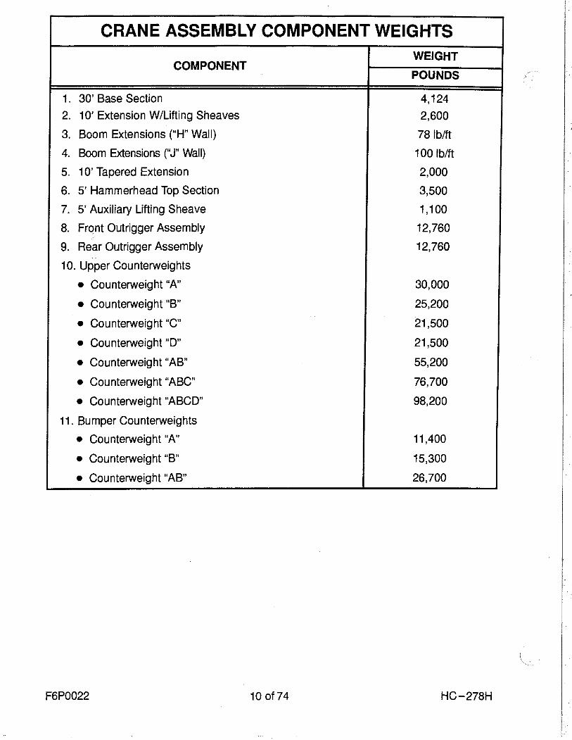
n CounterweightsTotal - 98,200 Ibs. (44 544 kg)
�A� ctwt. - 30,000 Ibs. (13 608 kg)�B� ctwt. - 25,200 Ibs. (11 431 kg)"C" ctwt. - 21,500 lbs. (9 752 kg)"D" ctwt. - 21,500 lbs. (9 752 kg)
n Attachment - Open ThroatBoom - Tubular; two section basic boom 60'(18.29 m) long.
Base section - 30' (9.14 m) long, 80" (2.03 m)wide, 68" (1.73 m) deep. Lifting lugs on topside of base section to attach carrying links forcarrying boom base section.
Boom extensions - Available in 10' (3.05 m),20' (6.10 m), 30' (9.14 m), 40' (12.19 m) and50' (15.24 m) lengths; 80" (2.03 m) wide,68" (1. 73 m) deep, centerline-to-centerlineof main chords. Extensions furnished withappropriate length pendants, and one hoistline deflector roller per extension.
Boom connections - In-line, tapered pins.
Boom top section - Open throat; 30' (9.14 m)long.
Boompoint machinery - Six 21" (0.53 m) rootdiameter head sheaves mounted on anti-friction bearings.
Boom midpoint suspension pendants -Required for all boom lengths exceeding 240'(73.15 m). Pendants connected at 140'(42.67 m) point of boom.
Maximum open throat boom lengthpermitted - 330' (100.58 m) boom or 300'(91.44) + 100' (30.48 m) boom and jibcombination.
n Attachment - HammerheadBoom - Tubular; three section basic boom 45'(13.71 m) long.
Base section - 30' (9.14 m) long; 80" (2.03 m)wide, 68" (1.73 m) deep.
"J" Wall Straight Boom Extensions - Availablein 10' (3.05 m), 20' (6.10 m) and 30' (9.14 m)lengths.Note: When using hammerhead attachmentthe first 40' (12.19 m) of boom extension mustbe "J" wall extensions. All other extensionsare standard open throat boom extensions.
Straight Boom Extensions - Available in 10'(3.05 m), 20' (6.10 m), 30' (9.14 m), 40' (12.19m) and 50' (15.24 m) lengths; 80" (2.03 m)wide, 68" (1.73 m) deep, centerline-to-centerline of main chords. In making upvarious boom lengths, straight extensionsmust be arranged in the boom as outlined inCrane Rating Manual.
Tapered Boom Extension - 10' (3.05 m) long;80" (2.03 m) wide, 68" (1.73 m) deep at lower
end and 55" (1.40 m) wide, 41" (1.04 m)deep at top end.
Note: Tapered boom extension must alwaysbe used as last boom section prior tomounting hammerhead top section.
Hammerhead Top Section - 5' (1.52 m)long; 55" (1.40 m) wide, 41" (1.04 m) deeplower end.
Maximum hammerhead boom lengthpermitted - 245' (74.68 m).
Boompoint Machinery - Six 21" (0.53 m) rootdiameter sheaves; mounted on anti-frictionbearings.
Items Applicable to BothHammerhead and OpenThroat Tip Booms
n Boom StopsDual lever type; connected to upper frameand top of boom base section. Spring loadedbumper ends.
n Boom Live MastMounted on front of upper frame; supportsboomhoist bridle, spreader bar and boommidpoint suspension pendants. Mast 35'(10.67 m) long; may be used as short boomfor handling counterweight, outriggerassemblies, etc. in machine stripdownand for boom assembly/disassembly.
Boom live mast stops - Incorporated withboom stops; manually positioned when usinglive mast as short boom.
n Boomhoist BridleBridle contains nine 15" (0.38 m) rootdiameter sheaves (for 18-part boomhoistreeving) and two 15" (0.38 m) root diameterauxiliary load hoist sheaves which enableboom live mast to be used as short boomfor machine assembly/disassembly.
Sheaves mounted on anti-friction bearings.
Boom pendants - Standard; furnished forbasic boom lengths plus appropriate lengthpendants with each boom extension.
Deflector rollers - Deflect load hoist wirerope off boom to avoid chafing; steel rollersmounted on anti-friction bearings. One rollerfurnished with each boom extension.
n JibTubular; two-piece basic jib 30' (9.14 m) long;32" (0.81 m) wide, 24" (0.61 m) deep atcenterline of connections. Alloy steel tubularchords 2-1/4" (57 mm) outside diameter.
Base section -13' 3" (4.04 m) long.
Jib extensions - Available in 10' (3.05 m) and20' (6.1 m) lengths with appropriate lengthpendants.
Jib connections - In-line, tapered pins.
Tip section -15' (4.57 m) long; equipped withsingle peak sheave 21" (0.53 m) rootdiameter, heat treated and mounted on anti-friction bearings. Anchor provided at peak ofjib tip section for two-part load hoist wire rope(whipline) connection.
Maximum jib length permitted - 100'(30.48 m). All jib lengths may be mounted at5°, 15° or 25° offset to boom.
n Jib Mast17' 10" (5.44 m) long, mounted on jib basesection. Two deflector sheaves mountedwithin mast to guide whipline; mounted onanti-friction bearings. Two equalizer sheavesmounted on top of mast - one for jib frontstayline, one for jib backstay line.
Jib staylines - Front and back staylines.Back staylines vary in length depending ondegree of jib offset from boom centerline;back staylines attached at bottom end ofboom top section.
Jib stops - Telescoping type; pinned from jibmast to boom top section and from jib mast tojib base section.
Boomfeet - 4" (101.60 mm) wide on 66"(1.68 m) centers; 5" (0.13 m) diameterboomfoot pins. Pins hydraulically removed/inserted for ease in stripdown. Double-actinghydraulic cylinder mounts on frame betweenboomfoot lugs.
Boomfoot pins - one connected to cylinderrod end, the other connected to the cylinderbody - are pushed in, or pulled from,connection with boomfeet.
Auxiliary Equipment
n Boom Angle IndicatorPendulum type; mounted on boom basesection.
n Anti Two-Block SystemStandard - A switch mounted on the boompeak activates a buzzer to warn the operatorof a two-block condition and simultaneouslydisengages hoist function while applying thehoist brakes.
n Rated Capacity LimiterStandard; PAT DS-350 rated capacity limiter.
n Hook BlocksBlocks, or weighted ball with swivel hook,optional - refer to price list.
Link-Belt Construction Equipment Company Lexington, KentuckyA unit of Sumitomo Construction Machinery Co., Ltd.
® Link-Belt is a registered trademark. Copyright 1997. All rights reserved. We are constantly improving our products and therefore reserve the right to change designs and specifications.