SPECIFICATIONS FOR WELD CONSUMABLES FOR FLUX CORED...
38
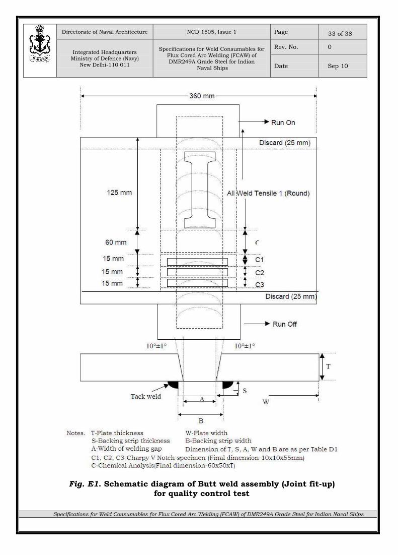
NCD 1505 ISSUE-1 SEP 2010 SPECIFICATIONS FOR WELD CONSUMABLES FOR FLUX CORED ARC WELDING (FCAW) OF DMR249A GRADE STEEL FOR INDIAN NAVAL SHIPS (Valid up to Aug 2015) Issuing Authority Integrated Headquarters, Ministry of Defence (Navy) Directorate of Naval Architecture D-II Wing, Sena Bhawan New Delhi-110 011 NCD SPECIFICATION
Transcript of SPECIFICATIONS FOR WELD CONSUMABLES FOR FLUX CORED...
NCD 1505 ISSUE-1 SEP 2010
SPECIFICATIONS FOR WELD CONSUMABLES FOR FLUX CORED ARC WELDING (FCAW) OF DMR249A GRADE
STEEL FOR INDIAN NAVAL SHIPS
(Valid up to Aug 2015)
Issuing Authority
Integrated Headquarters,
Ministry of Defence (Navy)
Directorate of Naval Architecture
D-II Wing, Sena Bhawan
New Delhi-110 011
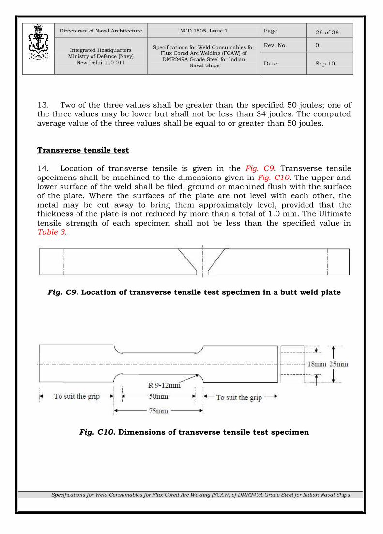
NCD SPECIFICATION
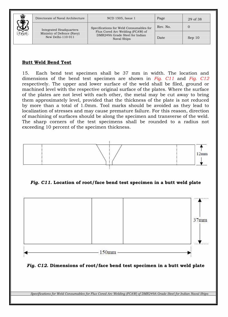
Directorate of Naval Architecture NCD 1505, Issue 1 Page
Integrated Headquarters Ministry of Defence (Navy)
New Delhi-110 011
Specifications for Weld Consumables for
Flux Cored Arc Welding (FCAW) of DMR249A Grade Steel for Indian
Naval Ships
Rev. No. 0
Date Sep 10
Specifications for Weld Consumables for Flux Cored Arc Welding (FCAW) of DMR249A Grade Steel for Indian Naval Ships
2 of 38
RECORD OF AMENDMENTS
S.No. Amendment Authority Date Signature
1.
2.
3.
4.
5.
6.
7.
8.
9.
10.
Directorate of Naval Architecture NCD 1505, Issue 1 Page
Integrated Headquarters Ministry of Defence (Navy)
New Delhi-110 011
Specifications for Weld Consumables for
Flux Cored Arc Welding (FCAW) of DMR249A Grade Steel for Indian
Naval Ships
Rev. No. 0
Date Sep 10
Specifications for Weld Consumables for Flux Cored Arc Welding (FCAW) of DMR249A Grade Steel for Indian Naval Ships
3 of 38
NCD SPECIFICATION
NCD 1505 ISSUE 1 SEP 2010
SPECIFICATIONS FOR WELD CONSUMABLES FOR FLUX CORED ARC WELDING (FCAW) OF DMR249A GRADE
STEEL FOR INDIAN NAVAL SHIPS
Directorate of Naval Architecture NCD 1505, Issue 1 Page
Integrated Headquarters Ministry of Defence (Navy)
New Delhi-110 011
Specifications for Weld Consumables for
Flux Cored Arc Welding (FCAW) of DMR249A Grade Steel for Indian
Naval Ships
Rev. No. 0
Date Sep 10
Specifications for Weld Consumables for Flux Cored Arc Welding (FCAW) of DMR249A Grade Steel for Indian Naval Ships
4 of 38
CONDITIONS OF RELEASE
1. This NCD specification has been prepared for the use of the Indian Navy and of its contractors in the execution of contracts for the Indian Navy.
2. This document is Indian Navy copyright and the information therein may be subjected to Indian Navy rights. It is not to be released, reproduced or published without written permission of the Integrated Headquarters, Ministry of
Defence(Navy).
3. Indian Navy reserves the right to amend or modify the contents of this specification without consulting or informing any holder of the specification.
4. This specification may call for the use of processes, substances and procedures that may be injurious to health if adequate precautions are not taken.
It refers only to technical suitability and in no way absolves either the supplier or the user from statutory obligations relating to health and safety at any stage of manufacture or use.
5. Where attention is drawn to hazards, those quoted may not necessarily be exhaustive.
6. This specification is the property of the Indian Navy and, unless otherwise
authorized in writing by the Integrated Headquarters, Ministry of Defence(Navy), must be returned on completion of the contract or submission of the tender, in connection with which it is issued.
7. Enquiries in connection to this NCD specification maybe made from
Directorate of Naval Architecture, Integrated Headquarters, Ministry of Defence(Navy), Sena Bhavan, New Delhi, Tele No. 011-23011580/23010942, Fax No. 011-23010126.
8. Unless otherwise specified, reference in this specification to any document means the issue and all amendments to the document current at the date of
issue or subsequent amendments to this specification.
Directorate of Naval Architecture NCD 1505, Issue 1 Page
Integrated Headquarters Ministry of Defence (Navy)
New Delhi-110 011
Specifications for Weld Consumables for
Flux Cored Arc Welding (FCAW) of DMR249A Grade Steel for Indian
Naval Ships
Rev. No. 0
Date Sep 10
Specifications for Weld Consumables for Flux Cored Arc Welding (FCAW) of DMR249A Grade Steel for Indian Naval Ships
5 of 38
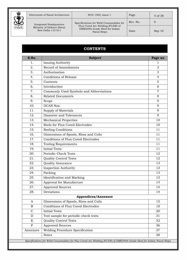
CONTENTS
S.No. Subject Page no
1. Issuing Authority 1
2. Record of Amendments 2
3. Authorisation 3
4. Conditions of Release 4
5. Contents 5
6. Introduction 6
7. Commonly Used Symbols and Abbreviations 7
8. Related Documents 8
9. Scope 9
10. DCAN Nos. 9
11. Supply of Materials 9
12. Diameter and Tolerances 9
13. Mechanical Properties 10
14. Reels for Flux Cored Electrodes 10
15. Reeling Conditions 11
16. Dimensions of Spools, Rims and Coils 11
17. Conditions of Flux Cored Electrodes 11
18. Testing Requirements 11
19. Initial Tests 11
20. Periodic Check Tests 12
21. Quality Control Tests 12
22. Quality Assurance 13
23. Inspection Authority 13
24. Packing 13
25. Identification and Marking 13
26. Approval for Manufacture 14
27. Approved Sources 14
28. Deviations 14
Appendices/Annexure
A Dimensions of Spools, Rims and Coils 15
B Conditions of Flux Cored Electrodes 18
C Initial Tests 20
D Test sample for periodic check tests 31
E Quality Control Tests 32
F Approved Sources 36
Annexure Welding Procedure Specification 37
Notes 38
Directorate of Naval Architecture NCD 1505, Issue 1 Page
Integrated Headquarters Ministry of Defence (Navy)
New Delhi-110 011
Specifications for Weld Consumables for
Flux Cored Arc Welding (FCAW) of DMR249A Grade Steel for Indian
Naval Ships
Rev. No. 0
Date Sep 10
Specifications for Weld Consumables for Flux Cored Arc Welding (FCAW) of DMR249A Grade Steel for Indian Naval Ships
6 of 38
INTRODUCTION
1. This NCD Specification is sponsored by the Indian Navy, Integrated Headquarters, Ministry of Defence (Navy), Principal Director, Directorate of Naval Architecture, Sena Bhavan, New Delhi-110 011.
2. It is to be applied as required by any Ministry of Defence (Navy) contract for
supply of Weld Consumables for Gas Metal Arc Welding of DMR249A Grade Steel for Indian Naval Ships.
3. If it is found to be technically unsuitable for any particular requirement the sponsor is to be informed in writing of the circumstances with a copy to Principal
Director, Directorate of Naval Architecture, Integrated Headquarters, Ministry of Defence (Navy), Sena Bhavan, New Delhi-110 011.
4. Any user to this Specification may propose an amendment to it which are:-
(a) Not directly applicable to a particular contract are to be made to the
sponsor of the NCD.
(b) Directly applicable to a particular contract are to be dealt with using existing procedures or as specified in the contract.
5. No alteration is to be made to this NCD specification except by the issue of formal amendment.
6. Unless otherwise stated, reference in this NCD specification to approval, approved, authorised or similar terms are by the Integrated Headquarters,
Ministry of Defence (Navy). 7. The Naval specifications have been formulated from NMRL, Ambernath
specification no. NMRL/MMat/GMAW-NCM221/R0-2006 as the weld consumables have been developed through NMRL.
8. This specification is valid for a period of 05 years from the date of issue or as and when amended.
Directorate of Naval Architecture NCD 1505, Issue 1 Page
Integrated Headquarters Ministry of Defence (Navy)
New Delhi-110 011
Specifications for Weld Consumables for
Flux Cored Arc Welding (FCAW) of DMR249A Grade Steel for Indian
Naval Ships
Rev. No. 0
Date Sep 10
Specifications for Weld Consumables for Flux Cored Arc Welding (FCAW) of DMR249A Grade Steel for Indian Naval Ships
7 of 38
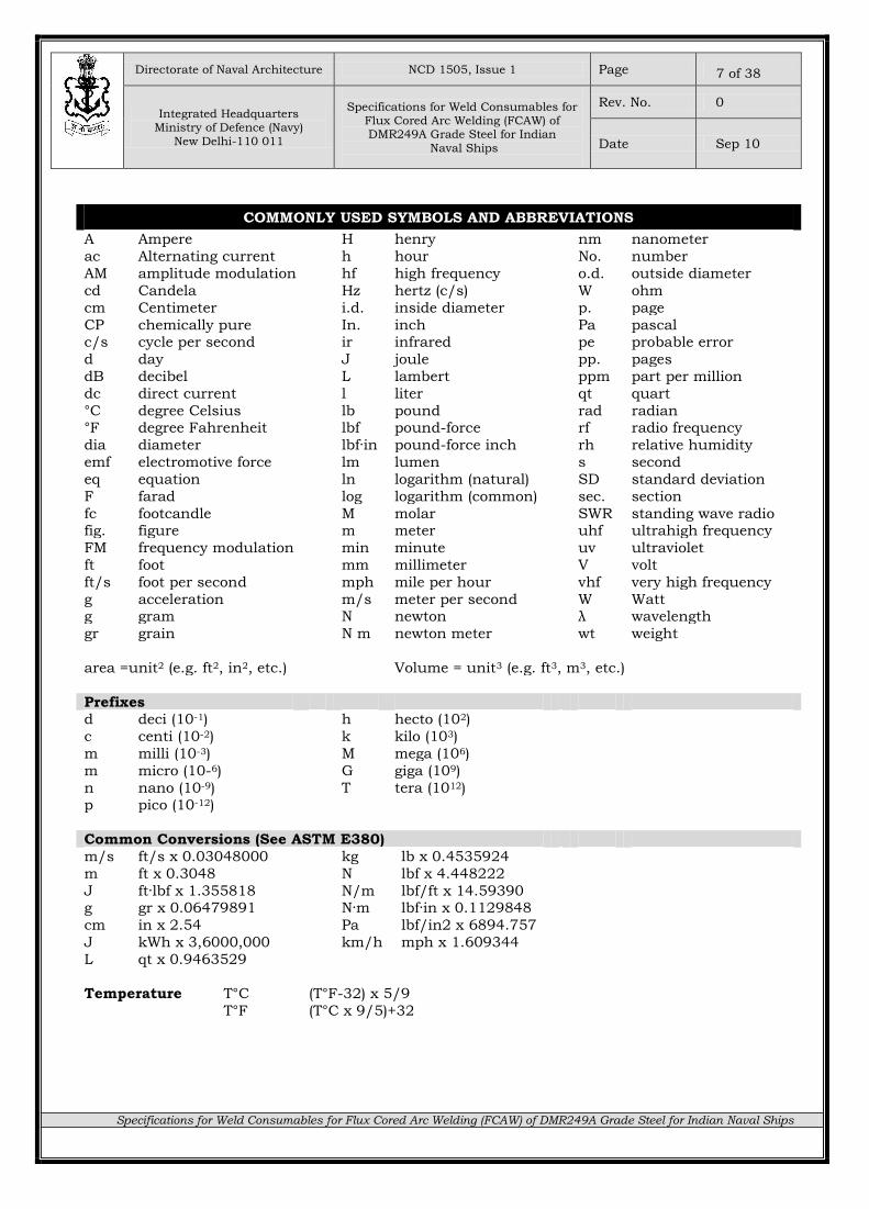
COMMONLY USED SYMBOLS AND ABBREVIATIONS
A Ampere H henry nm nanometer
ac Alternating current h hour No. number
AM amplitude modulation hf high frequency o.d. outside diameter
cd Candela Hz hertz (c/s) W ohm
cm Centimeter i.d. inside diameter p. page
CP chemically pure In. inch Pa pascal c/s cycle per second ir infrared pe probable error
d day J joule pp. pages
dB decibel L lambert ppm part per million
dc direct current l liter qt quart
°C degree Celsius lb pound rad radian °F degree Fahrenheit lbf pound-force rf radio frequency
dia diameter lbf·in pound-force inch rh relative humidity
emf electromotive force lm lumen s second
eq equation ln logarithm (natural) SD standard deviation
F farad log logarithm (common) sec. section
fc footcandle M molar SWR standing wave radio fig. figure m meter uhf ultrahigh frequency
FM frequency modulation min minute uv ultraviolet
ft foot mm millimeter V volt
ft/s foot per second mph mile per hour vhf very high frequency
g acceleration m/s meter per second W Watt g gram N newton λ wavelength
gr grain N m newton meter wt weight
area =unit2 (e.g. ft2, in2, etc.) Volume = unit3 (e.g. ft3, m3, etc.)
Prefixes d deci (10-1) h hecto (102)
c centi (10-2) k kilo (103)
m milli (10-3) M mega (106)
m micro (10-6) G giga (109)
n nano (10-9) T tera (1012) p pico (10-12)
Common Conversions (See ASTM E380)
m/s ft/s x 0.03048000 kg lb x 0.4535924
m ft x 0.3048 N lbf x 4.448222
J ft·lbf x 1.355818 N/m lbf/ft x 14.59390 g gr x 0.06479891 N·m lbf·in x 0.1129848
cm in x 2.54 Pa lbf/in2 x 6894.757
J kWh x 3,6000,000 km/h mph x 1.609344
L qt x 0.9463529
Temperature T°C (T°F-32) x 5/9
T°F (T°C x 9/5)+32
Directorate of Naval Architecture NCD 1505, Issue 1 Page
Integrated Headquarters Ministry of Defence (Navy)
New Delhi-110 011
Specifications for Weld Consumables for
Flux Cored Arc Welding (FCAW) of DMR249A Grade Steel for Indian
Naval Ships
Rev. No. 0
Date Sep 10
Specifications for Weld Consumables for Flux Cored Arc Welding (FCAW) of DMR249A Grade Steel for Indian Naval Ships
8 of 38
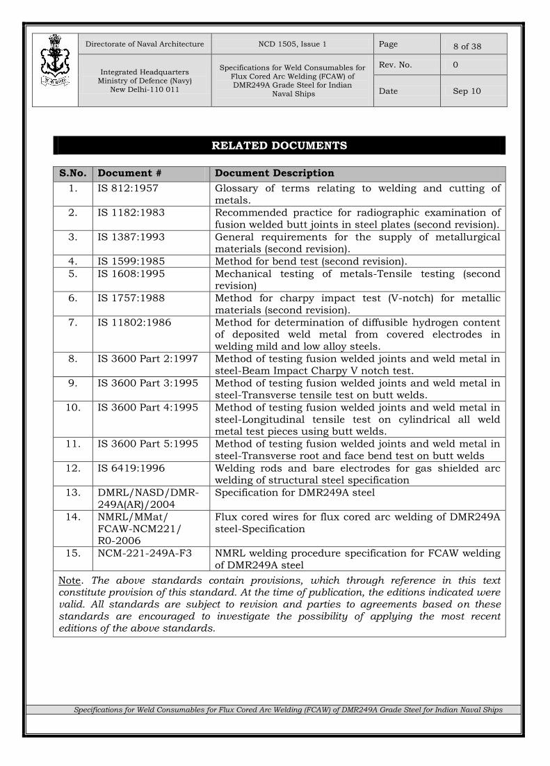
RELATED DOCUMENTS
S.No. Document # Document Description
1. IS 812:1957 Glossary of terms relating to welding and cutting of metals.
2. IS 1182:1983 Recommended practice for radiographic examination of
fusion welded butt joints in steel plates (second revision).
3. IS 1387:1993 General requirements for the supply of metallurgical materials (second revision).
4. IS 1599:1985 Method for bend test (second revision).
5. IS 1608:1995 Mechanical testing of metals-Tensile testing (second revision)
6. IS 1757:1988 Method for charpy impact test (V-notch) for metallic materials (second revision).
7. IS 11802:1986 Method for determination of diffusible hydrogen content of deposited weld metal from covered electrodes in welding mild and low alloy steels.
8. IS 3600 Part 2:1997 Method of testing fusion welded joints and weld metal in steel-Beam Impact Charpy V notch test.
9. IS 3600 Part 3:1995 Method of testing fusion welded joints and weld metal in steel-Transverse tensile test on butt welds.
10. IS 3600 Part 4:1995
Method of testing fusion welded joints and weld metal in steel-Longitudinal tensile test on cylindrical all weld metal test pieces using butt welds.
11. IS 3600 Part 5:1995 Method of testing fusion welded joints and weld metal in steel-Transverse root and face bend test on butt welds
12. IS 6419:1996 Welding rods and bare electrodes for gas shielded arc welding of structural steel specification
13. DMRL/NASD/DMR-249A(AR)/2004
Specification for DMR249A steel
14. NMRL/MMat/ FCAW-NCM221/ R0-2006
Flux cored wires for flux cored arc welding of DMR249A steel-Specification
15. NCM-221-249A-F3 NMRL welding procedure specification for FCAW welding of DMR249A steel
Note. The above standards contain provisions, which through reference in this text constitute provision of this standard. At the time of publication, the editions indicated were valid. All standards are subject to revision and parties to agreements based on these standards are encouraged to investigate the possibility of applying the most recent editions of the above standards.
Directorate of Naval Architecture NCD 1505, Issue 1 Page
Integrated Headquarters Ministry of Defence (Navy)
New Delhi-110 011
Specifications for Weld Consumables for
Flux Cored Arc Welding (FCAW) of DMR249A Grade Steel for Indian
Naval Ships
Rev. No. 0
Date Sep 10
Specifications for Weld Consumables for Flux Cored Arc Welding (FCAW) of DMR249A Grade Steel for Indian Naval Ships
9 of 38
NCD 1505, Issue 1, Sep 2010
SPECIFICATIONS FOR WELD CONSUMABLES FOR FLUX CORED ARC WELDING
(FCAW) OF DMR249A GRADE STEEL FOR INDIAN NAVAL SHIPS
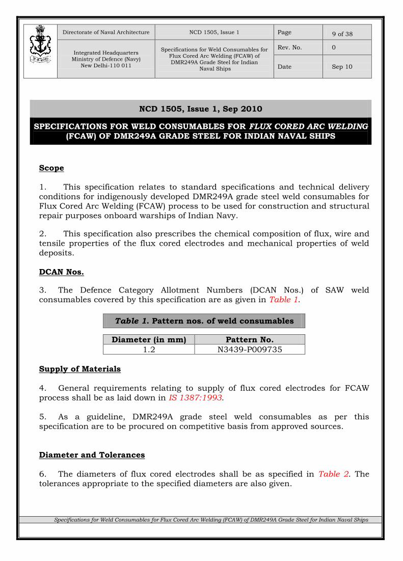
Scope 1. This specification relates to standard specifications and technical delivery
conditions for indigenously developed DMR249A grade steel weld consumables for Flux Cored Arc Welding (FCAW) process to be used for construction and structural repair purposes onboard warships of Indian Navy.
2. This specification also prescribes the chemical composition of flux, wire and
tensile properties of the flux cored electrodes and mechanical properties of weld deposits.
DCAN Nos.
3. The Defence Category Allotment Numbers (DCAN Nos.) of SAW weld consumables covered by this specification are as given in Table 1.
Table 1. Pattern nos. of weld consumables
Diameter (in mm) Pattern No.
1.2 N3439-P009735
Supply of Materials
4. General requirements relating to supply of flux cored electrodes for FCAW
process shall be as laid down in IS 1387:1993. 5. As a guideline, DMR249A grade steel weld consumables as per this
specification are to be procured on competitive basis from approved sources.
Diameter and Tolerances
6. The diameters of flux cored electrodes shall be as specified in Table 2. The tolerances appropriate to the specified diameters are also given.
Directorate of Naval Architecture NCD 1505, Issue 1 Page
Integrated Headquarters Ministry of Defence (Navy)
New Delhi-110 011
Specifications for Weld Consumables for
Flux Cored Arc Welding (FCAW) of DMR249A Grade Steel for Indian
Naval Ships
Rev. No. 0
Date Sep 10
Specifications for Weld Consumables for Flux Cored Arc Welding (FCAW) of DMR249A Grade Steel for Indian Naval Ships
10 of 38
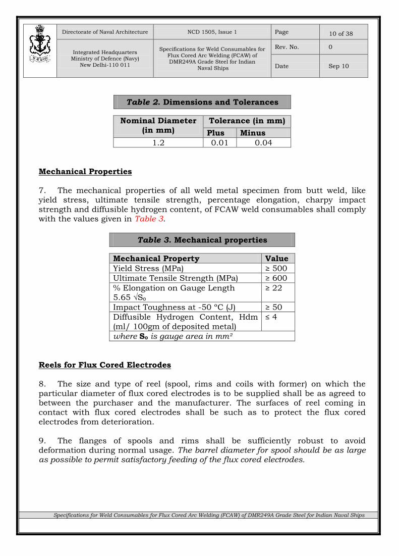
Table 2. Dimensions and Tolerances
Nominal Diameter (in mm)
Tolerance (in mm)
Plus Minus
1.2 0.01 0.04
Mechanical Properties
7. The mechanical properties of all weld metal specimen from butt weld, like yield stress, ultimate tensile strength, percentage elongation, charpy impact
strength and diffusible hydrogen content, of FCAW weld consumables shall comply with the values given in Table 3.
Table 3. Mechanical properties
Mechanical Property Value
Yield Stress (MPa) ≥ 500
Ultimate Tensile Strength (MPa) ≥ 600
% Elongation on Gauge Length 5.65 √Sₒ
≥ 22
Impact Toughness at -50 ºC (J) ≥ 50
Diffusible Hydrogen Content, Hdm
(ml/ 100gm of deposited metal)
≤ 4
where Sₒ is gauge area in mm²
Reels for Flux Cored Electrodes
8. The size and type of reel (spool, rims and coils with former) on which the
particular diameter of flux cored electrodes is to be supplied shall be as agreed to between the purchaser and the manufacturer. The surfaces of reel coming in contact with flux cored electrodes shall be such as to protect the flux cored
electrodes from deterioration.
9. The flanges of spools and rims shall be sufficiently robust to avoid deformation during normal usage. The barrel diameter for spool should be as large as possible to permit satisfactory feeding of the flux cored electrodes.
Directorate of Naval Architecture NCD 1505, Issue 1 Page
Integrated Headquarters Ministry of Defence (Navy)
New Delhi-110 011
Specifications for Weld Consumables for
Flux Cored Arc Welding (FCAW) of DMR249A Grade Steel for Indian
Naval Ships
Rev. No. 0
Date Sep 10
Specifications for Weld Consumables for Flux Cored Arc Welding (FCAW) of DMR249A Grade Steel for Indian Naval Ships
11 of 38
Reeling Conditions
10. The flux cored electrode shall be wound on the reel in one continuous length and shall be free from kinks, sharp bends or twists. So that it is free to unwind without restriction.
11. The outer layer of flux cored electrode shall not be closer than 3 mm to the
flange periphery on spools having a flange diameter of 100 mm and not closer than 10 mm to the flange periphery on spools having other flange diameters.
Dimensions of Spools, Rims and Coils
12. The dimensions and tolerances of the spools, rims and coils are given in Appendix A.
Conditions of Flux Cored Electrodes 13. The conditions of flux cored electrodes like finish, temper, cast and helix are
given in Appendix B.
Testing Requirements
14. Flux cored electrodes shall be subjected to the following tests for assessing the mechanical properties of the deposited weld metal and the usability of an electrode for a particular welding position:-
(a) Initial certification tests
(b) Periodic tests
(c) Quality control tests.
15. The parent metal used for test plates shall be DMR249A steel.
Initial Tests
16. Initial tests are certifying or proving tests for each type or modified type of flux cored electrode. The details of these tests are given in Appendix C.
Directorate of Naval Architecture NCD 1505, Issue 1 Page
Integrated Headquarters Ministry of Defence (Navy)
New Delhi-110 011
Specifications for Weld Consumables for
Flux Cored Arc Welding (FCAW) of DMR249A Grade Steel for Indian
Naval Ships
Rev. No. 0
Date Sep 10
Specifications for Weld Consumables for Flux Cored Arc Welding (FCAW) of DMR249A Grade Steel for Indian Naval Ships
12 of 38
Periodic Check Tests
17. The periodic check tests comprise of the following tests selected from the initial tests, and are meant to be repeated at intervals to provide evidence that the electrodes currently produced, possess the properties proved in the initial tests:-
(a) One longitudinal all weld metal tensile test from a butt welded plate
(b) Three all weld metal charpy impact tests from a butt welded plate
(c) Diffusible hydrogen estimation test
18. The periodic check tests shall be conducted at least once in a year. These tests shall also be conducted when the production of the flux cored electrode is
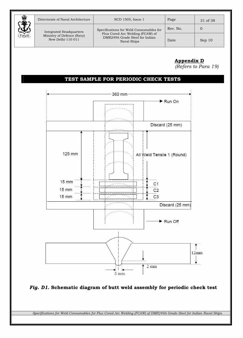
resumed after stoppage for more than six months. 19. For tests at Para 17(a) and 17(b), the test sample (as shown in Appendix D)
shall be taken from single test assembly welded at vertical up (3G) position. Welding procedure details for preparation of weld assembly shall be as per
Annexure to Appendix C.
Quality Control Tests
20. By means of suitable system of control, the manufacturer shall satisfy that the composition and quality of the flux cored electrodes currently produced are similar to the flux cored electrode, which was subjected to initial qualifying tests.
Manufacturer shall ensure that the result of quality control tests and date of manufacture of flux cored electrodes is traced from the batch number of the relevant details, or both. For the purpose of this specification, a batch is defined as a lot of solid bare electrodes of any one size and identified by a heat number of material from single heat of metal. 21. The manufacturer on request shall make available to the approving and
certifying authorities the records maintained for quality control, for ensuring that the composition and quality of all the flux cored electrodes currently produced are similar to those flux cored electrodes subjected to initial and periodic check tests.
22. The details of quality control tests shall be as per Appendix E.
Directorate of Naval Architecture NCD 1505, Issue 1 Page
Integrated Headquarters Ministry of Defence (Navy)
New Delhi-110 011
Specifications for Weld Consumables for
Flux Cored Arc Welding (FCAW) of DMR249A Grade Steel for Indian
Naval Ships
Rev. No. 0
Date Sep 10
Specifications for Weld Consumables for Flux Cored Arc Welding (FCAW) of DMR249A Grade Steel for Indian Naval Ships
13 of 38
Quality Assurance
23. The quality assurance standards to be achieved for acceptance of weld consumables shall be based on specified requirements/limits with respect to the quality control tests as per Para 20 to 22 above.
Inspection Authority 24. Directorate of Quality Assurance (Naval) (DQAN), New Delhi is the inspection
authority for inspection and clearance of DMR249A grade steel weld consumables as per this specification during procurement by Material Organisations and
shipyards.
25. The inspection shall be undertaken in accordance with approved Quality Assurance Plan.
Packing
26. Reels of flux cored electrodes shall be suitably packed to guard against damage, combination or deterioration during storage, transit and inspection.
Marking
27. The following information shall be clearly marked on each package of flux cored electrodes for easy identification and shall be stamped by DQAN, the
clearing agency:-
(a) Certification coding
(b) Name of manufacturer
(c) Trade designation of flux cored electrode
(d) Size
(e) Cast number
Directorate of Naval Architecture NCD 1505, Issue 1 Page
Integrated Headquarters Ministry of Defence (Navy)
New Delhi-110 011
Specifications for Weld Consumables for
Flux Cored Arc Welding (FCAW) of DMR249A Grade Steel for Indian
Naval Ships
Rev. No. 0
Date Sep 10
Specifications for Weld Consumables for Flux Cored Arc Welding (FCAW) of DMR249A Grade Steel for Indian Naval Ships
14 of 38
Approval for Manufacture 28. Weld consumables manufacturers, desirous of producing weld consumables
in accordance this specification for Indian Navy, shall approach IHQ, MoD(N) with details of proposed products. The approval may be granted based on assessment of manufacturing capabilities and suitability of proposed product during testing
process to ensure quality production of weld consumables.
Approved Sources
29. Two sources have been approved by IHQ, MoD(N) to manufacture weld consumables in accordance with this specification and supply to procurement
agencies of Indian Navy and Shipyards for construction and repair of Indian Navy ships. The contact details of approved manufacturer and their products are given in Appendix F.
Deviations
30. Any major deviation from the requirement specified in above paragraphs above, which affect the performance of the weld consumables, shall be referred to
IHQ, MoD(N) for clarification.
* * * * *
Directorate of Naval Architecture NCD 1505, Issue 1 Page
Integrated Headquarters Ministry of Defence (Navy)
New Delhi-110 011
Specifications for Weld Consumables for
Flux Cored Arc Welding (FCAW) of DMR249A Grade Steel for Indian
Naval Ships
Rev. No. 0
Date Sep 10
Specifications for Weld Consumables for Flux Cored Arc Welding (FCAW) of DMR249A Grade Steel for Indian Naval Ships
15 of 38
Appendix A
(Refers to Para 12)
DIMENSIONS OF SPOOLS, RIMS AND COILS
Dimensions of Spool
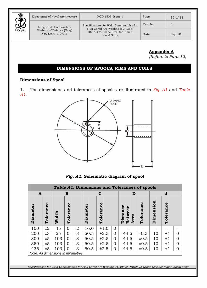
1. The dimensions and tolerances of spools are illustrated in Fig. A1 and Table A1.
Fig. A1. Schematic diagram of spool
Table A1. Dimensions and Tolerances of spools
A B C D d
Dia
mete
r
Tole
ran
ce
Wid
th
Tole
ran
ce
Dia
mete
r
Tole
ran
ce
Dis
tan
ce
Betw
een
Axes
Tole
ran
ce
Dim
en
sio
n
Tole
ran
ce
100 ±2 45 0 -2 16.0 +1.0 0 - - - - -
200 ±3 55 0 -3 50.5 +2.5 0 44.5 -0.5 10 +1 0
300 ±5 103 0 -3 50.5 +2.5 0 44.5 ±0.5 10 +1 0
350 ±5 103 0 -3 50.5 +2.5 0 44.5 ±0.5 10 +1 0
435 ±5 103 0 -3 50.5 ±2.5 0 44.5 ±0.5 10 +1 0 Note. All dimensions in millimetres
Directorate of Naval Architecture NCD 1505, Issue 1 Page
Integrated Headquarters Ministry of Defence (Navy)
New Delhi-110 011
Specifications for Weld Consumables for
Flux Cored Arc Welding (FCAW) of DMR249A Grade Steel for Indian
Naval Ships
Rev. No. 0
Date Sep 10
Specifications for Weld Consumables for Flux Cored Arc Welding (FCAW) of DMR249A Grade Steel for Indian Naval Ships
16 of 38
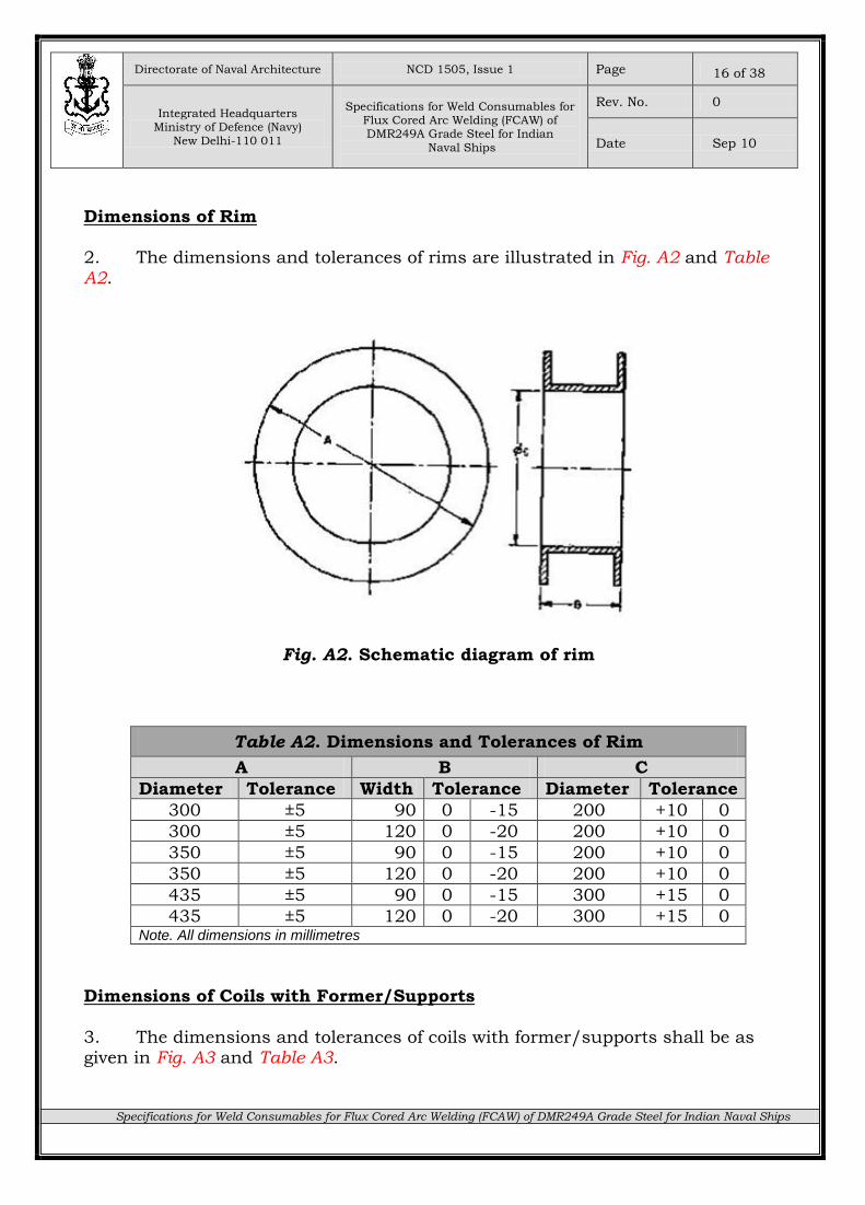
Dimensions of Rim 2. The dimensions and tolerances of rims are illustrated in Fig. A2 and Table A2.
Fig. A2. Schematic diagram of rim
Table A2. Dimensions and Tolerances of Rim
A B C
Diameter Tolerance Width Tolerance Diameter Tolerance
300 ±5 90 0 -15 200 +10 0
300 ±5 120 0 -20 200 +10 0
350 ±5 90 0 -15 200 +10 0
350 ±5 120 0 -20 200 +10 0
435 ±5 90 0 -15 300 +15 0
435 ±5 120 0 -20 300 +15 0 Note. All dimensions in millimetres
Dimensions of Coils with Former/Supports
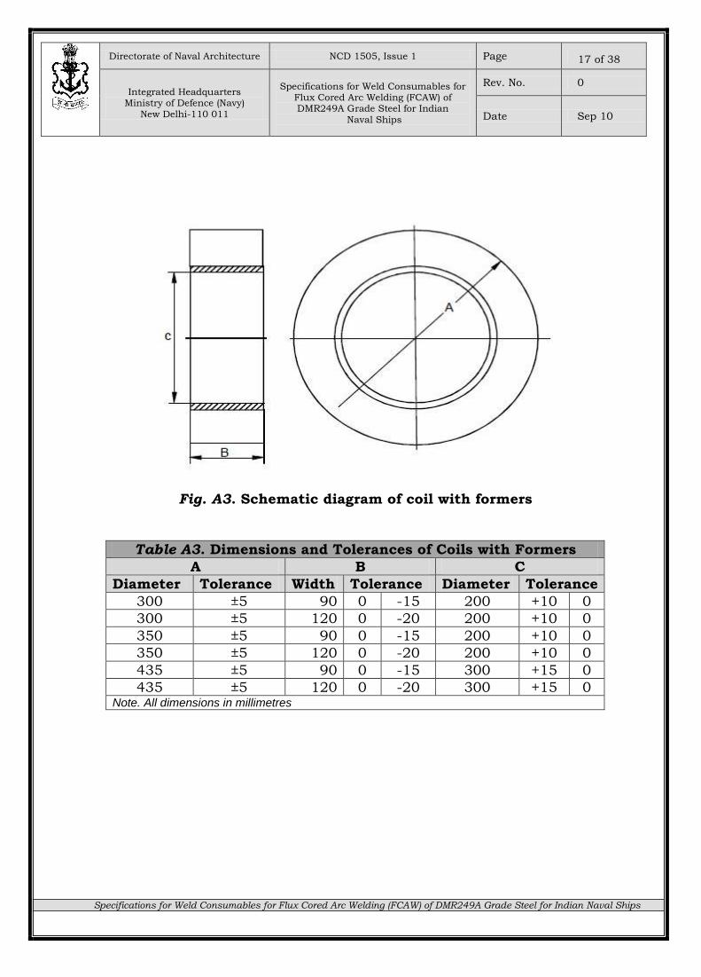
3. The dimensions and tolerances of coils with former/supports shall be as given in Fig. A3 and Table A3.
Directorate of Naval Architecture NCD 1505, Issue 1 Page
Integrated Headquarters Ministry of Defence (Navy)
New Delhi-110 011
Specifications for Weld Consumables for
Flux Cored Arc Welding (FCAW) of DMR249A Grade Steel for Indian
Naval Ships
Rev. No. 0
Date Sep 10
Specifications for Weld Consumables for Flux Cored Arc Welding (FCAW) of DMR249A Grade Steel for Indian Naval Ships
17 of 38
Fig. A3. Schematic diagram of coil with formers
Table A3. Dimensions and Tolerances of Coils with Formers
A B C
Diameter Tolerance Width Tolerance Diameter Tolerance
300 ±5 90 0 -15 200 +10 0
300 ±5 120 0 -20 200 +10 0
350 ±5 90 0 -15 200 +10 0
350 ±5 120 0 -20 200 +10 0
435 ±5 90 0 -15 300 +15 0
435 ±5 120 0 -20 300 +15 0 Note. All dimensions in millimetres
Directorate of Naval Architecture NCD 1505, Issue 1 Page
Integrated Headquarters Ministry of Defence (Navy)
New Delhi-110 011
Specifications for Weld Consumables for
Flux Cored Arc Welding (FCAW) of DMR249A Grade Steel for Indian
Naval Ships
Rev. No. 0
Date Sep 10
Specifications for Weld Consumables for Flux Cored Arc Welding (FCAW) of DMR249A Grade Steel for Indian Naval Ships
18 of 38
Appendix B (Refers to Para 13)
CONDITIONS OF FLUX CORED ELECTRODES
Finish
1. Flux cored electrode shall have a smooth finish and be free from surface imperfections, corrosion products, grease, excessive oxide or other foreign matter, which would adversely affect the properties of the weld or the operation of the
welding equipment. The flux cored electrode shall be supplied with a protective copper coating; it shall be a uniform well-bonded, smooth coating being applied
over a thoroughly clean surface. The flux cored electrode shall be suitably coated in order to minimize the conductivity resistance.
Temper
2. The temper of the flux cored electrode shall be such that they are suitable
for uninterrupted feeding on automatic or semi automatic welding equipment. The maximum tensile strength of as manufactured flux cored electrode that is wound on spools of 300mm and greater in diameter should be 900 MPa.
Cast
3. The cast of coiled flux cored electrode shall be such as to have imparted a curvature to the flux cored electrode so that a specimen sufficient in length to
form one loop or a maximum 3 m when cut from the package and laid on a flat surface without restraint, shall form a circle or portion thereof of the diameter
shown for the cast in Table B1.
Table B1. Diameters of Cast and Helix
Type of Package Standard Size (in mm)
Cast (in mm)
Maximum Helix (in mm)
100mm spool 1.2 200-230 13
All except 100mm spool ≥ 1.2 380 25
Directorate of Naval Architecture NCD 1505, Issue 1 Page
Integrated Headquarters Ministry of Defence (Navy)
New Delhi-110 011
Specifications for Weld Consumables for
Flux Cored Arc Welding (FCAW) of DMR249A Grade Steel for Indian
Naval Ships
Rev. No. 0
Date Sep 10
Specifications for Weld Consumables for Flux Cored Arc Welding (FCAW) of DMR249A Grade Steel for Indian Naval Ships
19 of 38
Helix 4. The helix of coiled flux cored electrode as executed by the ring used to
determine the cast, when placed in flat surface without restraint, shall be such that the maximum distance from any point on the flux cored electrode to flat
surface shall not exceed the dimension shown for helix in Table B1.
Directorate of Naval Architecture NCD 1505, Issue 1 Page
Integrated Headquarters Ministry of Defence (Navy)
New Delhi-110 011
Specifications for Weld Consumables for
Flux Cored Arc Welding (FCAW) of DMR249A Grade Steel for Indian
Naval Ships
Rev. No. 0
Date Sep 10
Specifications for Weld Consumables for Flux Cored Arc Welding (FCAW) of DMR249A Grade Steel for Indian Naval Ships
20 of 38
Appendix C
(Refers to Para 16)
INITIAL TESTS
General
1. The initial tests shall comprise of the following, whose details are given in the
succeeding paragraphs:-
(a) The test assembly shall be prepared and tested.
(b) Radiographic quality test from a butt-welded plate.
(c) Three longitudinal all weld metal tensile test from a butt-welded plate.
(d) Three all weld metal charpy impact tests from a butt-welded plate.
(e) Three transverse tensile tests from a butt-welded plate.
(f) Three transverse face and three transverse roots bend tests from a butt-
welded plate.
(g) Diffusible hydrogen estimation test.
All Weld Metal Mechanical Tests from butt-welded plates
2. Weld Assembly. A butt joint configuration as shown in Fig. C1, shall be welded by FCAW process, using 12mm thick DMR249A steel plates, in vertical up (3G) position. The width of the test plate shall not be less than 150mm and should
be along the rolling direction.
3. The plate edges shall be prepared to form a single V-joint, with an included angle of 60° and root face of 2mm and root gap of 3.0mm. The bevelling of the plate edges shall be carried out by machining or mechanized gas cutting. In the
mechanized gas cutting, any remaining scale shall be removed from the bevelled edges. The bevelled edge of the plate shall be along the direction transverse to
rolling direction. 4. The butt welded plates shall be tack welded at three locations, by using 3
Nos. steel restraining plates of dimension (360mm x 50mm x 10mm) as shown in Fig. C1. The tack welds will be made at four different positions for each restraining
plate. Butt welding of the plates shall be carried out as per the Welding Procedure Specification given in Annexure.
5. After being welded, the test piece shall not be subjected to any heat treatment.
Directorate of Naval Architecture NCD 1505, Issue 1 Page
Integrated Headquarters Ministry of Defence (Navy)
New Delhi-110 011
Specifications for Weld Consumables for
Flux Cored Arc Welding (FCAW) of DMR249A Grade Steel for Indian
Naval Ships
Rev. No. 0
Date Sep 10
Specifications for Weld Consumables for Flux Cored Arc Welding (FCAW) of DMR249A Grade Steel for Indian Naval Ships
21 of 38
Fig. C1. Schematic diagram of Butt Weld assembly (Joint fit-up)
with restraining pieces
Directorate of Naval Architecture NCD 1505, Issue 1 Page
Integrated Headquarters Ministry of Defence (Navy)
New Delhi-110 011
Specifications for Weld Consumables for
Flux Cored Arc Welding (FCAW) of DMR249A Grade Steel for Indian
Naval Ships
Rev. No. 0
Date Sep 10
Specifications for Weld Consumables for Flux Cored Arc Welding (FCAW) of DMR249A Grade Steel for Indian Naval Ships
22 of 38
6. After welding, the test piece shall be cut by sawing or machining to form the required test specimen as indicated in Fig. C2, C3 and C4. The method employed for the separation of the test specimens shall be such as to cause minimum
deformation and minimum heating.
7. The best method is usually by machining. If thermal cutting or other methods which could affect the cut surfaces are used, the cuts shall be made at a distance from the test specimen greater or equal to 8 mm but in any case sufficient
according to the process used, not to induce alterations which could alter the test results. When the assembly has been welded completely, it shall be allowed to cool in still air to room temperature. The portion including the weld shall then be
removed by cutting away the excess plate at the places indicated in Fig. C2, C3 and C4.
8. Cutting along the chain lines (shown by vertical) may be done mechanically or
by machine gas cutting. Along the longitudinal boundaries (shown by horizontal broken lines ‘-----’) of the parts to be machined into impact test pieces cutting
should be done by mechanical methods only. 9. The yield stress, ultimate tensile strength, percentage elongation and charpy
impact strength and diffusible hydrogen content shall comply with the values given in Table 3. These tests shall be carried out on three different production
batches to prove consistency in production. The testing samples shall be drawn from the plates welded in both flat down hand and vertical up welding positions. Each set of test from Para 1(b) to (f) above shall consist of butt-welded test plates of
sufficient length to allow the cutting out of test specimens of the prescribed number and size.
Radiographic Test
10. All butt-welded test assemblies shall be subjected to radiographic test as per
IS:1182. The radiograph shall not show crack or incomplete fusion. The radiograph acceptance standard in respect of porosity and slag inclusions is indicated in Table C1. In making the evaluation for radiographic acceptance
standard, a length of 25 mm of the welded assembly shall be excluded from both ends.
Directorate of Naval Architecture NCD 1505, Issue 1 Page
Integrated Headquarters Ministry of Defence (Navy)
New Delhi-110 011
Specifications for Weld Consumables for
Flux Cored Arc Welding (FCAW) of DMR249A Grade Steel for Indian
Naval Ships
Rev. No. 0
Date Sep 10
Specifications for Weld Consumables for Flux Cored Arc Welding (FCAW) of DMR249A Grade Steel for Indian Naval Ships
23 of 38
Fig. C2. Schematic diagram of location of test specimens
in butt weld assembly
Directorate of Naval Architecture NCD 1505, Issue 1 Page
Integrated Headquarters Ministry of Defence (Navy)
New Delhi-110 011
Specifications for Weld Consumables for
Flux Cored Arc Welding (FCAW) of DMR249A Grade Steel for Indian
Naval Ships
Rev. No. 0
Date Sep 10
Specifications for Weld Consumables for Flux Cored Arc Welding (FCAW) of DMR249A Grade Steel for Indian Naval Ships
24 of 38
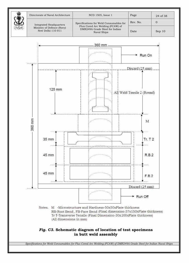
Fig. C3. Schematic diagram of location of test specimens
in butt weld assembly
Directorate of Naval Architecture NCD 1505, Issue 1 Page
Integrated Headquarters Ministry of Defence (Navy)
New Delhi-110 011
Specifications for Weld Consumables for
Flux Cored Arc Welding (FCAW) of DMR249A Grade Steel for Indian
Naval Ships
Rev. No. 0
Date Sep 10
Specifications for Weld Consumables for Flux Cored Arc Welding (FCAW) of DMR249A Grade Steel for Indian Naval Ships
25 of 38
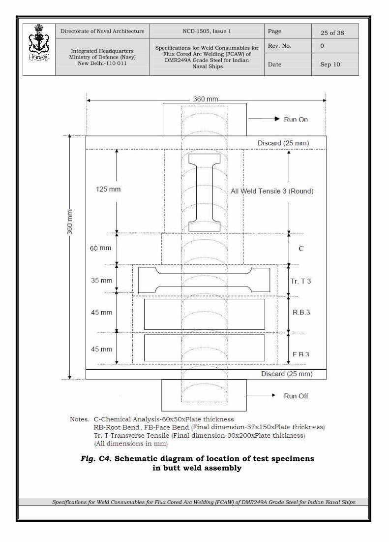
Fig. C4. Schematic diagram of location of test specimens
in butt weld assembly
Directorate of Naval Architecture NCD 1505, Issue 1 Page
Integrated Headquarters Ministry of Defence (Navy)
New Delhi-110 011
Specifications for Weld Consumables for
Flux Cored Arc Welding (FCAW) of DMR249A Grade Steel for Indian
Naval Ships
Rev. No. 0
Date Sep 10
Specifications for Weld Consumables for Flux Cored Arc Welding (FCAW) of DMR249A Grade Steel for Indian Naval Ships
26 of 38
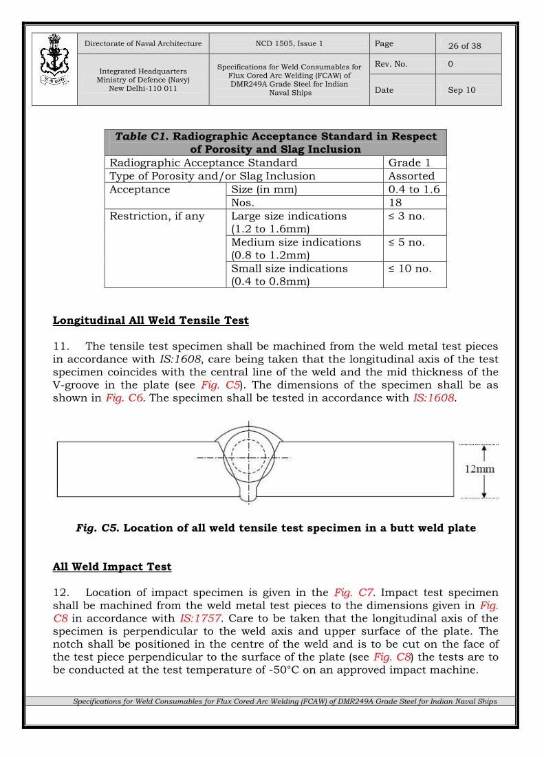
Table C1. Radiographic Acceptance Standard in Respect
of Porosity and Slag Inclusion
Radiographic Acceptance Standard Grade 1
Type of Porosity and/or Slag Inclusion Assorted
Acceptance Size (in mm) 0.4 to 1.6
Nos. 18
Restriction, if any Large size indications (1.2 to 1.6mm)
≤ 3 no.
Medium size indications (0.8 to 1.2mm)
≤ 5 no.
Small size indications (0.4 to 0.8mm)
≤ 10 no.
Longitudinal All Weld Tensile Test
11. The tensile test specimen shall be machined from the weld metal test pieces
in accordance with IS:1608, care being taken that the longitudinal axis of the test specimen coincides with the central line of the weld and the mid thickness of the V-groove in the plate (see Fig. C5). The dimensions of the specimen shall be as
shown in Fig. C6. The specimen shall be tested in accordance with IS:1608.
Fig. C5. Location of all weld tensile test specimen in a butt weld plate
All Weld Impact Test
12. Location of impact specimen is given in the Fig. C7. Impact test specimen
shall be machined from the weld metal test pieces to the dimensions given in Fig. C8 in accordance with IS:1757. Care to be taken that the longitudinal axis of the specimen is perpendicular to the weld axis and upper surface of the plate. The
notch shall be positioned in the centre of the weld and is to be cut on the face of the test piece perpendicular to the surface of the plate (see Fig. C8) the tests are to
be conducted at the test temperature of -50°C on an approved impact machine.
Directorate of Naval Architecture NCD 1505, Issue 1 Page
Integrated Headquarters Ministry of Defence (Navy)
New Delhi-110 011
Specifications for Weld Consumables for
Flux Cored Arc Welding (FCAW) of DMR249A Grade Steel for Indian
Naval Ships
Rev. No. 0
Date Sep 10
Specifications for Weld Consumables for Flux Cored Arc Welding (FCAW) of DMR249A Grade Steel for Indian Naval Ships
27 of 38
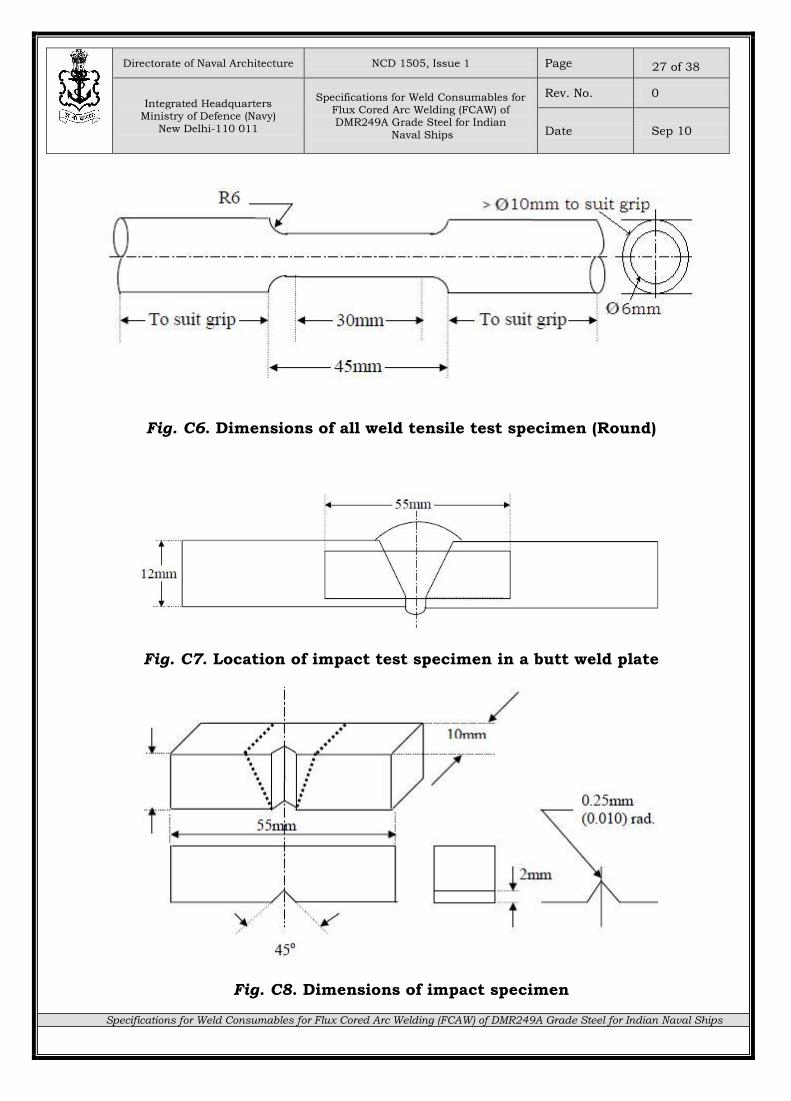
Fig. C6. Dimensions of all weld tensile test specimen (Round)
Fig. C7. Location of impact test specimen in a butt weld plate
Fig. C8. Dimensions of impact specimen
Directorate of Naval Architecture NCD 1505, Issue 1 Page
Integrated Headquarters Ministry of Defence (Navy)
New Delhi-110 011
Specifications for Weld Consumables for
Flux Cored Arc Welding (FCAW) of DMR249A Grade Steel for Indian
Naval Ships
Rev. No. 0
Date Sep 10
Specifications for Weld Consumables for Flux Cored Arc Welding (FCAW) of DMR249A Grade Steel for Indian Naval Ships
28 of 38
13. Two of the three values shall be greater than the specified 50 joules; one of the three values may be lower but shall not be less than 34 joules. The computed
average value of the three values shall be equal to or greater than 50 joules.
Transverse tensile test
14. Location of transverse tensile is given in the Fig. C9. Transverse tensile
specimens shall be machined to the dimensions given in Fig. C10. The upper and lower surface of the weld shall be filed, ground or machined flush with the surface
of the plate. Where the surfaces of the plate are not level with each other, the metal may be cut away to bring them approximately level, provided that the thickness of the plate is not reduced by more than a total of 1.0 mm. The Ultimate
tensile strength of each specimen shall not be less than the specified value in Table 3.
Fig. C9. Location of transverse tensile test specimen in a butt weld plate
Fig. C10. Dimensions of transverse tensile test specimen
Directorate of Naval Architecture NCD 1505, Issue 1 Page
Integrated Headquarters Ministry of Defence (Navy)
New Delhi-110 011
Specifications for Weld Consumables for
Flux Cored Arc Welding (FCAW) of DMR249A Grade Steel for Indian
Naval Ships
Rev. No. 0
Date Sep 10
Specifications for Weld Consumables for Flux Cored Arc Welding (FCAW) of DMR249A Grade Steel for Indian Naval Ships
29 of 38
Butt Weld Bend Test
15. Each bend test specimen shall be 37 mm in width. The location and dimensions of the bend test specimen are shown in Fig. C11 and Fig. C12
respectively. The upper and lower surface of the weld shall be filed, ground or machined level with the respective original surface of the plates. Where the surface of the plates are not level with each other, the metal may be cut away to bring
them approximately level, provided that the thickness of the plate is not reduced by more than a total of 1.0mm. Tool marks should be avoided as they lead to localization of stresses and may cause premature failure. For this reason, direction
of machining of surfaces should be along the specimen and transverse of the weld. The sharp corners of the test specimens shall be rounded to a radius not
exceeding 10 percent of the specimen thickness.
Fig. C11. Location of root/face bend test specimen in a butt weld plate
Fig. C12. Dimensions of root/face bend test specimen in a butt weld plate
Directorate of Naval Architecture NCD 1505, Issue 1 Page
Integrated Headquarters Ministry of Defence (Navy)
New Delhi-110 011
Specifications for Weld Consumables for
Flux Cored Arc Welding (FCAW) of DMR249A Grade Steel for Indian
Naval Ships
Rev. No. 0
Date Sep 10
Specifications for Weld Consumables for Flux Cored Arc Welding (FCAW) of DMR249A Grade Steel for Indian Naval Ships
30 of 38
16. Both type of bend tests, one with face and one with root in tension shall be carried out from each butt weld assembly. The test specimens shall be bent through 180° over a mandrel having a diameter equal to three times the thickness
of the specimen in accordance with IS:1599. The electrode shall be deemed to be satisfactory, if on completion of the test no crack or defect at the outer surface of
the test specimen is greater than 3 mm measured across the test specimen or 1.5 mm measured along the length of the test specimen. Premature failure at corners of the test specimen shall not be considered as a case for rejection.
Diffusible Hydrogen Evaluation Test
17. This test shall be carried out preferably using 1.2mm size flux cored
electrode. The test shall be carried out in accordance with IS:11802 and mercury method shall only be used for this determination.
18. The diffusible hydrogen content shall comply with the level given in Table 3.
Retests
19. Where any test specimen fails to fulfil the test requirements, twice the number of the test specimens made for that test for the initial certification or
periodic test shall be prepared by using flux cored electrode from the same batch wherever possible and submitted only for the tests in which failure occurred. The flux cored electrode shall not be accepted as having passed that test unless the
tests on additional specimen are satisfactory.
Directorate of Naval Architecture NCD 1505, Issue 1 Page
Integrated Headquarters Ministry of Defence (Navy)
New Delhi-110 011
Specifications for Weld Consumables for
Flux Cored Arc Welding (FCAW) of DMR249A Grade Steel for Indian
Naval Ships
Rev. No. 0
Date Sep 10
Specifications for Weld Consumables for Flux Cored Arc Welding (FCAW) of DMR249A Grade Steel for Indian Naval Ships
31 of 38
Appendix D (Refers to Para 19)
TEST SAMPLE FOR PERIODIC CHECK TESTS
Fig. D1. Schematic diagram of butt weld assembly for periodic check test
Directorate of Naval Architecture NCD 1505, Issue 1 Page
Integrated Headquarters Ministry of Defence (Navy)
New Delhi-110 011
Specifications for Weld Consumables for
Flux Cored Arc Welding (FCAW) of DMR249A Grade Steel for Indian
Naval Ships
Rev. No. 0
Date Sep 10
Specifications for Weld Consumables for Flux Cored Arc Welding (FCAW) of DMR249A Grade Steel for Indian Naval Ships
32 of 38
Appendix E (Refers to Para 22)
QUALITY CONTROL TESTS
General
1. The various quality control tests are given in the succeeding paragraphs.
Weld Metal Assembly
2. A test assembly shall be welded in the flat position. The metal for plates used in preparing test piece shall be of DMR249A having a thickness of 12 mm. The test assembly shall be prepared as shown in Fig. E1 by depositing weld metal
between the chamfered edges of two (plates placed on backing strip). The dimensions of test assembly are given in Table E1. Welding parameters to be used
are as given in Table E2.
Table E1. Dimensions of Test Assembly for FCAW
Electrode Size
Plate Width,
C
Plate Thickness,
T
Width of Welding
gap, A
Backing Strip
Width, B (min.)
Thickness, S (min.)
1.2 150±10 15±3 12±1 A±10 > 6.5
All dimensions in mm
Table E2. Welding Parameters for FCAW
Welding Parameters Unit Range/Values
Electrode Size mm 1.2
Arc Voltage V 20-22
Welding Current A 120-140
Type of Current - DCRP
Travel Speed mm/sec 1.2-1.9
Inter-pass Temperature ºC 150
Gas flow rate lpm 14-18
Heat input kJ/mm 1-2.5
Directorate of Naval Architecture NCD 1505, Issue 1 Page
Integrated Headquarters Ministry of Defence (Navy)
New Delhi-110 011
Specifications for Weld Consumables for
Flux Cored Arc Welding (FCAW) of DMR249A Grade Steel for Indian
Naval Ships
Rev. No. 0
Date Sep 10
Specifications for Weld Consumables for Flux Cored Arc Welding (FCAW) of DMR249A Grade Steel for Indian Naval Ships
33 of 38
Fig. E1. Schematic diagram of Butt weld assembly (Joint fit-up)
for quality control test
Directorate of Naval Architecture NCD 1505, Issue 1 Page
Integrated Headquarters Ministry of Defence (Navy)
New Delhi-110 011
Specifications for Weld Consumables for
Flux Cored Arc Welding (FCAW) of DMR249A Grade Steel for Indian
Naval Ships
Rev. No. 0
Date Sep 10
Specifications for Weld Consumables for Flux Cored Arc Welding (FCAW) of DMR249A Grade Steel for Indian Naval Ships
34 of 38
3. The backing strip shall be tack welded to test assembly. The backing strip material shall be DMR249A steel.
4. The length of the plate shall be enough to accommodate a tensile test specimen and three charpy V-notch test specimens as shown in Fig. E1.
5. The plate’s edges shall be bevelled by machining or machine gas cutting. In the later case any remaining scale should be removed from the bevelled edges. The
surface of the backing strip should be free from rust or scale. 6. In order to counteract shrinkage deformation the test assembly should be
tack welded so that a level joint is obtained after welding.
7. Cutting of test assembly for preparing test specimen should be done as per Para 7 of Appendix C.
All weld Tensile Test
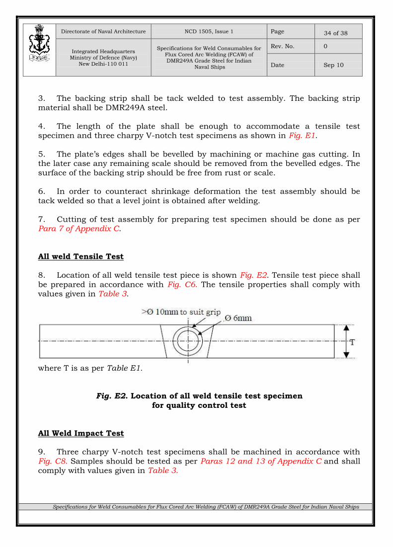
8. Location of all weld tensile test piece is shown Fig. E2. Tensile test piece shall
be prepared in accordance with Fig. C6. The tensile properties shall comply with values given in Table 3.
where T is as per Table E1.
Fig. E2. Location of all weld tensile test specimen
for quality control test
All Weld Impact Test 9. Three charpy V-notch test specimens shall be machined in accordance with
Fig. C8. Samples should be tested as per Paras 12 and 13 of Appendix C and shall comply with values given in Table 3.
Directorate of Naval Architecture NCD 1505, Issue 1 Page
Integrated Headquarters Ministry of Defence (Navy)
New Delhi-110 011
Specifications for Weld Consumables for
Flux Cored Arc Welding (FCAW) of DMR249A Grade Steel for Indian
Naval Ships
Rev. No. 0
Date Sep 10
Specifications for Weld Consumables for Flux Cored Arc Welding (FCAW) of DMR249A Grade Steel for Indian Naval Ships
35 of 38
All weld chemical composition 10. For chemical analysis the mid-section of the chemical analysis pad can be
used, Fig. E1, provided diluted weld metal is avoided. As an alternative the broken tensile test specimen can also be used for chemical analysis. The results of the
analysis shall meet the requirements as agreed to in Quality Assurance Plan (QAP).
Diffusible Hydrogen Evaluation Test
11. Diffusible hydrogen estimation test shall be done as per Paras 17 and 18 of Appendix C.
Chemical analysis of flux cored welding electrodes 12. The area to be sampled shall be taken from the combined transverse sections
that are obtained by bundling the flux cored electrodes after cutting them into suitable lengths or by folding them. The combined transverse area shall be cleaned
by grinding or pickling. 13. The copper coating shall be removed to expose the base metal before grinding.
The sample shall be collected by milling out the areas.
Directorate of Naval Architecture NCD 1505, Issue 1 Page
Integrated Headquarters Ministry of Defence (Navy)
New Delhi-110 011
Specifications for Weld Consumables for
Flux Cored Arc Welding (FCAW) of DMR249A Grade Steel for Indian
Naval Ships
Rev. No. 0
Date Sep 10
Specifications for Weld Consumables for Flux Cored Arc Welding (FCAW) of DMR249A Grade Steel for Indian Naval Ships
36 of 38
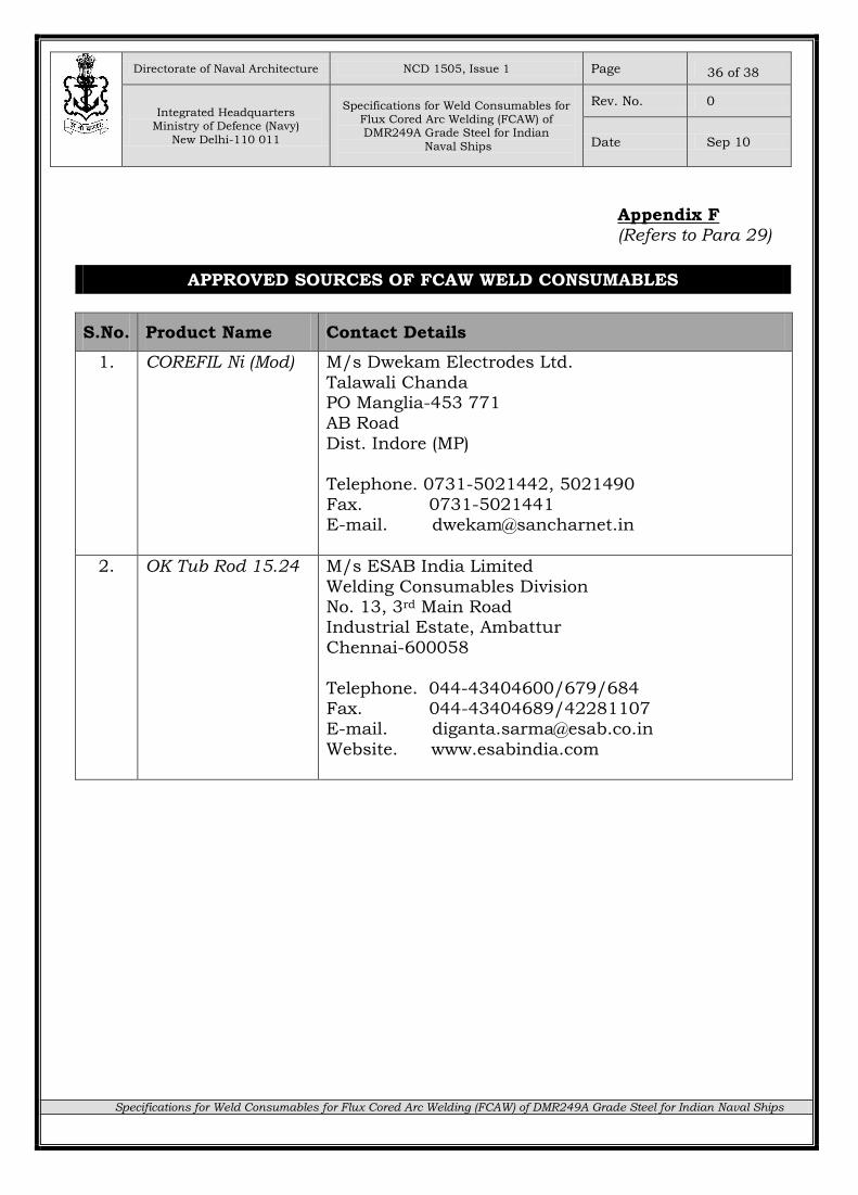
Appendix F (Refers to Para 29)
APPROVED SOURCES OF FCAW WELD CONSUMABLES
S.No. Product Name Contact Details
1. COREFIL Ni (Mod) M/s Dwekam Electrodes Ltd.
Talawali Chanda PO Manglia-453 771 AB Road
Dist. Indore (MP)
Telephone. 0731-5021442, 5021490 Fax. 0731-5021441 E-mail. [email protected]
2. OK Tub Rod 15.24 M/s ESAB India Limited
Welding Consumables Division No. 13, 3rd Main Road Industrial Estate, Ambattur
Chennai-600058
Telephone. 044-43404600/679/684 Fax. 044-43404689/42281107 E-mail. [email protected]
Website. www.esabindia.com
Directorate of Naval Architecture NCD 1505, Issue 1 Page
Integrated Headquarters Ministry of Defence (Navy)
New Delhi-110 011
Specifications for Weld Consumables for
Flux Cored Arc Welding (FCAW) of DMR249A Grade Steel for Indian
Naval Ships
Rev. No. 0
Date Sep 10
Specifications for Weld Consumables for Flux Cored Arc Welding (FCAW) of DMR249A Grade Steel for Indian Naval Ships
37 of 38
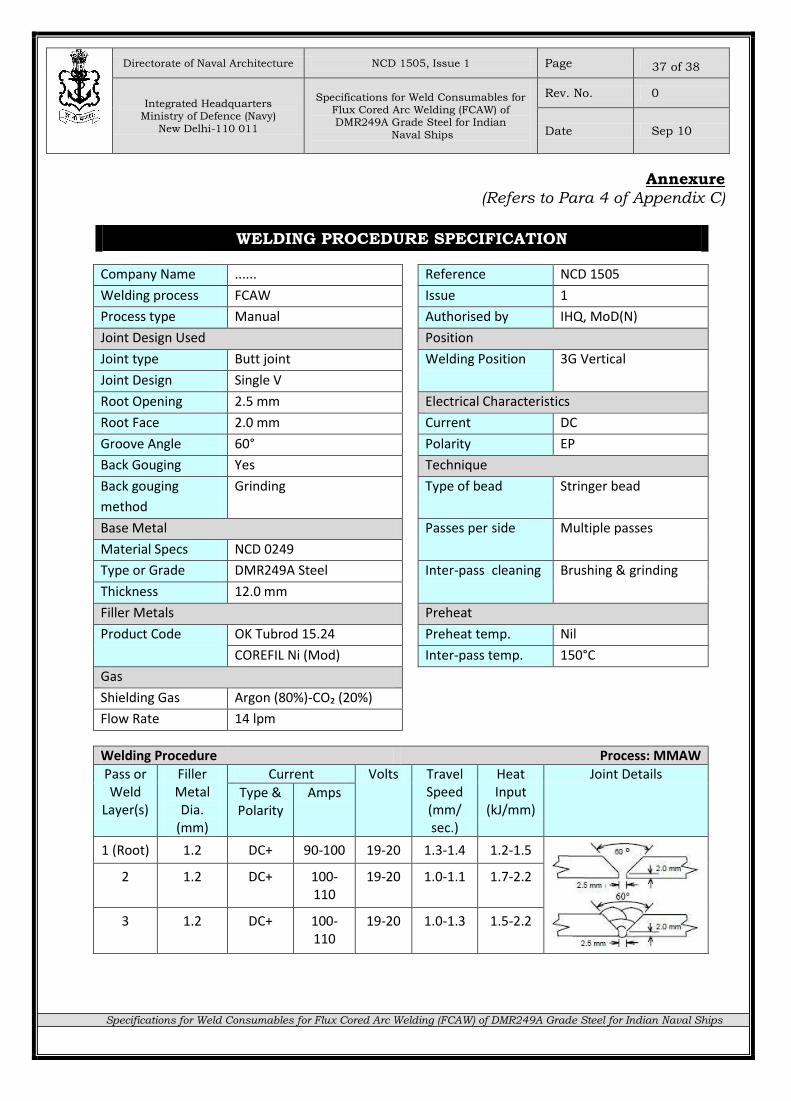
Annexure
(Refers to Para 4 of Appendix C)
WELDING PROCEDURE SPECIFICATION
Company Name ...... Reference NCD 1505
Welding process FCAW Issue 1
Process type Manual Authorised by IHQ, MoD(N)
Joint Design Used Position
Joint type Butt joint Welding Position 3G Vertical
Joint Design Single V
Root Opening 2.5 mm Electrical Characteristics
Root Face 2.0 mm Current DC
Groove Angle 60° Polarity EP
Back Gouging Yes Technique
Back gouging
method
Grinding Type of bead Stringer bead
Base Metal Passes per side Multiple passes
Material Specs NCD 0249
Type or Grade DMR249A Steel Inter-pass cleaning Brushing & grinding
Thickness 12.0 mm
Filler Metals Preheat
Product Code OK Tubrod 15.24 Preheat temp. Nil
COREFIL Ni (Mod) Inter-pass temp. 150°C
Gas
Shielding Gas Argon (80%)-CO₂ (20%)
Flow Rate 14 lpm
Welding Procedure Process: MMAW
Pass or Weld
Layer(s)
Filler Metal Dia.
(mm)
Current Volts Travel Speed (mm/
sec.)
Heat Input
(kJ/mm)
Joint Details
Type & Polarity
Amps
1 (Root) 1.2 DC+ 90-100 19-20 1.3-1.4 1.2-1.5
2 1.2 DC+ 100-110
19-20 1.0-1.1 1.7-2.2
3 1.2 DC+ 100-110
19-20 1.0-1.3 1.5-2.2
Directorate of Naval Architecture NCD 1505, Issue 1 Page
Integrated Headquarters Ministry of Defence (Navy)
New Delhi-110 011
Specifications for Weld Consumables for
Flux Cored Arc Welding (FCAW) of DMR249A Grade Steel for Indian
Naval Ships
Rev. No. 0
Date Sep 10
Specifications for Weld Consumables for Flux Cored Arc Welding (FCAW) of DMR249A Grade Steel for Indian Naval Ships
38 of 38
N O T E S