
Enclosed Flares NJ, Enclosed Flares PA, Thermal Oxidizers NJ, Thermal Oxidi...
MH27.2 – 2009 (a reaffirmation of MH27.2 – 2003)
Specifications for Enclosed Track Underhung Cranes and Monorail Systems
Abstract:
These proposed specifications apply to underhung cranes whose end trucks operate on the internal flange of a runway using enclosed track section; and to trolleys (carriers) operating on single-track monorail systems, including all curves, switches transfer devices, lift and drop sections, and associated equipment. Systems used for transporting personnel require special considerations and are not included in these specifications.
An Affiliated Trade Association of Material Handling Industry of America
A Division of Material Handling Industry 8720 Red Oak Blvd., Suite 201
Charlotte, NC 28217-3992 © 2009 Monorail Manufacturers Association, Inc. All rights reserved.
American National Standard Approval of an American National Standard requires verification by ANSI that the requirements for due process, consensus, and other criteria for approval have been met by the standards developer. Consensus is established when, in the judgment of the ANSI Board of Standards Review, substantial agreement has been reached by directly and materially affected interests. Substantial agreement means much more than a simple majority, but not necessarily unanimity. Consensus requires that all views and objections be considered, and that a concerted effort be made toward their resolution. The use of American National Standards is completely voluntary; their existence does not in any respect preclude anyone, whether he has approved the standards or not, from manufacturing, marketing, purchasing, or using products, processes or procedures not conforming to the standards. The American National Standards Institute does not develop standards and will in no circumstances give an interpretation of any American National Standard. Moreover, no person shall have the right or authority to issue an interpretation of an American National Standard in the name of the American National Standards Institute. Requests for interpretations should be addressed to the sponsor whose name appears on the title page of this standard. CAUTION NOTICE: This American National Standard may be revised or withdrawn at any time. The procedures of the American National Standards Institute require that action be taken periodically to reaffirm, revise or withdraw this standard. Purchasers of American National Standards may receive current information on all standards by calling or writing the American National Standards Institute. Published by Monorail Manufacturers Association, Inc. An Affiliated Trade Association of Material Handling Industry of America, a division of Material Handling Industry 8720 Red Oak Blvd., Suite 201, Charlotte, NC, 28217-3992 Telephone: (704) 676-1190 Fax: (704) 676-1199 www.mhia.org/mma © 2009 by Monorail Manufacturers Association, Inc. All rights reserved. No part of this publication may be reproduced in any form, in an electronic retrieval system or otherwise, without prior written permission of the publisher. Printed in the United States of America.
ANSI MH27.2 – 2009 (a reaffirmation of MH27.2 – 2003)
American National Standard
Specifications for Enclosed Track Underhung Cranes and Monorail Systems
Monorail Manufacturers Association, Inc. (MMA) An Affiliated Trade Association of Material Handling Industry of America, A Division of Material Handling Industry Approved December 2, 2009 American National Standards Institute, Inc.
AMERICAN NATIONAL STANDARD ANSI MH27.2 – 2009 (a reaffirmation of MH27.2-2003) Specifications for Enclosed Track Underhung Cranes and Monorail Systems
Disclaimer
This standard, which was developed under the ANSI Canvass method and approved by ANSI on December 2, 2009, represents suggested design practices and performance testing criteria for crane and monorail equipment. It was developed with the sole intent of offering information to parties engaged in the manufacture, marketing, purchase, or use of crane and monorail equipment. This standard is advisory only and acceptance is voluntary and the standard should be regarded as a guide that the user may or may not choose to adopt, modify, or reject. The information does not constitute a comprehensive safety program and should not be relied upon as such. Such a program should be developed and an independent safety adviser consulted to do so. Material Handling Industry (MHI), Monorail Manufacturers Association, Inc. and their members assume no responsibility and disclaim all liability of any kind, however arising, as a result of acceptance or use or alleged use of this standard. User specifically understands and agrees that MHI and Monorail Manufacturers Association, Inc. and their officers, agents, and employees shall not be liable under any legal theory or any kind for any action or failure to act with respect to the design, erection, installation, manufacture, preparation for sale, sale, characteristics, features, or delivery of anything covered by this standard. Any use of this information must be determined by the user to be in accordance with applicable federal, state, and local laws and regulations. MHI and Monorail Manufacturers Association, Inc. make no warranties of any kind, express, implied, or statutory, in connection with the information in this standard. MHI and Monorail Manufacturers Association, Inc. specifically disclaim all implied warranties of merchantability or of fitness for particular purpose. By referring to or otherwise employing this standard, the user agrees to defend, protect, indemnify, and hold MHI and Monorail Manufacturers Association, Inc. and their officers, agents, and employees harmless from and against all claims, losses, expenses, damages, and liabilities, direct, incidental, or consequential, arising from acceptance or use or alleged use of this standard, including loss of profits and reasonable attorneys' fees which may arise out of the acceptance or use or alleged use of this standard. The intent of this provision and of the user is to absolve and protect MHI and Monorail Manufacturers Association, Inc. and their officers, agents, and employees from any and all loss relating in any way to this standard, including those resulting from the user's own negligence.
ii
AMERICAN NATIONAL STANDARD ANSI MH27.2 – 2009 (a reaffirmation of MH27.2-2003) Specifications for Enclosed Track Underhung Cranes and Monorail Systems
Foreword (This foreword is not part of American National Standard MH27.2-2009) This standard was sponsored by the Monorail Manufacturers Association, Inc. in the interest of improved uniformity of patented track underhung crane and monorail performance and enhanced public safety. Since the intention of this standard is to encourage better communication between the manufacturer and the user, it should be regarded as a guide rather than a rigid specification. This standard has been subjected to the American National Standards Institute's Canvass Review and was approved as an ANSI Standard on September 10, 2003 as MH27.1-2003. Now the standard has been reaffirmed following editorial changes to add clarification to existing requirements. At the date of approval of this standard, the Monorail Manufacturers Association, Inc. consisted of the following member companies: Acco Material Handling Solutions Columbus McKinnon Corporation (CM) Demag Cranes & Components Corporation Gorbel, Inc. Ingersoll-Rand Co. Spanco, Inc. TC/American Monorail Inc. United States Monorail, Division of American Crane and Hoist Corp. Suggestions for improvement, and questions regarding interpretation of this standard will be welcome. They should be sent to: MH 27.2 Committee (MMA), Material Handling Industry of America, 8720 Red Oak Blvd., Suite 201, Charlotte, NC, 28217-3992 or [email protected].
iii
AMERICAN NATIONAL STANDARD ANSI MH27.2 – 2009 (a reaffirmation of MH27.2-2003) Specifications for Enclosed Track Underhung Cranes and Monorail Systems
SPECIFICATIONS FOR ENCLOSED TRACK UNDERHUNG CRANES AND MONORAIL SYSTEMS
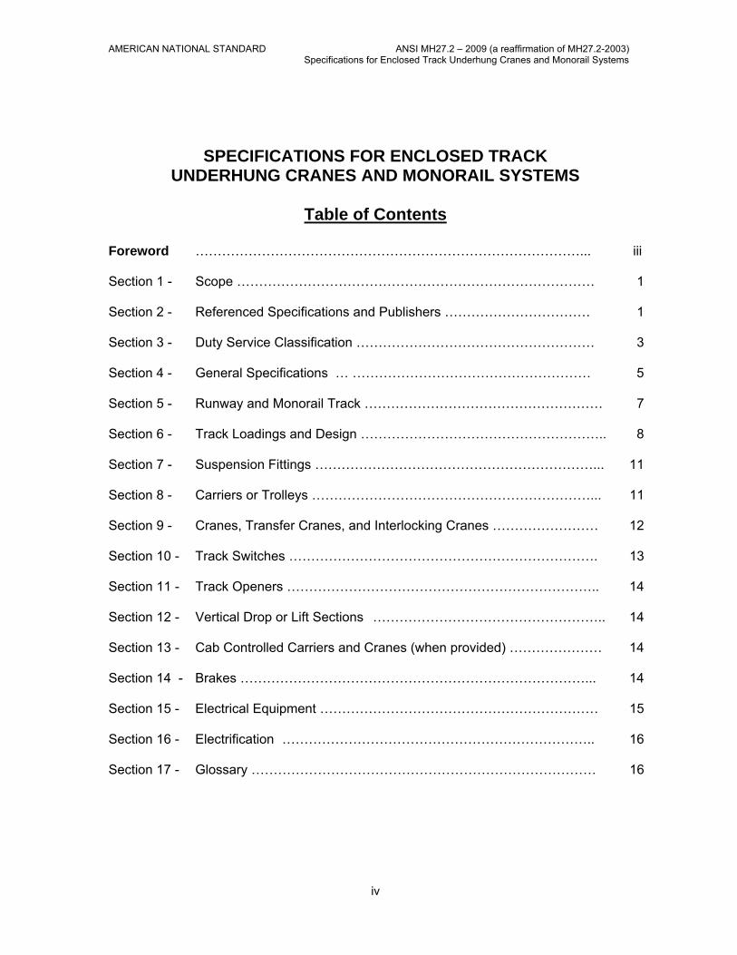
Table of Contents
Foreword ……………………………………………………………………………... iii Section 1 - Scope ……………………………………………………………………… 1 Section 2 - Referenced Specifications and Publishers …………………………… 1
Section 3 - Duty Service Classification ……………………………………………… 3 Section 4 - General Specifications … ……………………………………………… 5 Section 5 - Runway and Monorail Track ……………………………………………… 7 Section 6 - Track Loadings and Design ……………………………………………….. 8 Section 7 - Suspension Fittings ………………………………………………………... 11 Section 8 - Carriers or Trolleys ………………………………………………………... 11 Section 9 - Cranes, Transfer Cranes, and Interlocking Cranes …………………… 12 Section 10 - Track Switches ……………………………………………………………. 13 Section 11 - Track Openers …………………………………………………………….. 14 Section 12 - Vertical Drop or Lift Sections …………………………………………….. 14 Section 13 - Cab Controlled Carriers and Cranes (when provided) ………………… 14 Section 14 - Brakes ……………………………………………………………………... 14 Section 15 - Electrical Equipment ……………………………………………………… 15 Section 16 - Electrification …………………………………………………………….. 16 Section 17 - Glossary …………………………………………………………………… 16
iv
AMERICAN NATIONAL STANDARD ANSI MH27.2 – 2009 (a reaffirmation of MH27.2-2003) Specifications for Enclosed Track Underhung Cranes and Monorail Systems
List of Tables
Table 1 - Duty Service Classification ……………………………………………….. 4
List of Figures
Figure 1 - Runway Alignment Tolerance ……………………………………………….. 9
v
AMERICAN NATIONAL STANDARD ANSI MH27.2 – 2009 (a reaffirmation of MH27.2-2003) Specifications for Enclosed Track Underhung Cranes and Monorail Systems
SPECIFICATIONS FOR ENCLOSED TRACK UNDERHUNG CRANES AND MONORAIL SYSTEMS
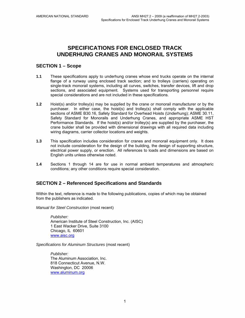
SECTION 1 – Scope 1.1 These specifications apply to underhung cranes whose end trucks operate on the internal
flange of a runway using enclosed track section; and to trolleys (carriers) operating on single-track monorail systems, including all curves, switches, transfer devices, lift and drop sections, and associated equipment. Systems used for transporting personnel require special considerations and are not included in these specifications.
1.2 Hoist(s) and/or trolley(s) may be supplied by the crane or monorail manufacturer or by the
purchaser. In either case, the hoist(s) and trolley(s) shall comply with the applicable sections of ASME B30.16, Safety Standard for Overhead Hoists (Underhung); ASME 30.11, Safety Standard for Monorails and Underhung Cranes, and appropriate ASME HST Performance Standards. If the hoist(s) and/or trolley(s) are supplied by the purchaser, the crane builder shall be provided with dimensional drawings with all required data including wiring diagrams, carrier collector locations and weights.
1.3 This specification includes consideration for cranes and monorail equipment only. It does
not include consideration for the design of the building, the design of supporting structure, electrical power supply, or erection. All references to loads and dimensions are based on English units unless otherwise noted.
1.4 Sections 1 through 14 are for use in normal ambient temperatures and atmospheric
conditions; any other conditions require special consideration. SECTION 2 – Referenced Specifications and Standards Within the text, reference is made to the following publications, copies of which may be obtained from the publishers as indicated. Manual for Steel Construction (most recent) Publisher: American Institute of Steel Construction, Inc. (AISC) 1 East Wacker Drive, Suite 3100 Chicago, IL 60601 www.aisc.org Specifications for Aluminum Structures (most recent) Publisher: The Aluminum Association, Inc. 818 Connecticut Avenue, N.W. Washington, DC 20006 www.aluminum.org
1
AMERICAN NATIONAL STANDARD ANSI MH27.2 – 2009 (a reaffirmation of MH27.2-2003) Specifications for Enclosed Track Underhung Cranes and Monorail Systems
ANSI Z244.1 (most recent) Personnel Protection – Lockout/Tagout of Energy Sources – Minimum Safety Standards
Publisher: American National Standards Institute, Inc. (ANSI) 11 West 42nd Street, 13th Floor New York, NY 10036 www.ansi.org ANSI/ASCE 7 (most recent) American Society of Civil Engineers Minimum Design Loads for
Buildings and Other Structures Publisher: American Society of Civil Engineers (ASCE) 345 East 47th Street New York, NY 10017 www.asce.org ASME B15.1 (most recent) Safety Standard for Mechanical Power Transmission Apparatus ASME B30.9 (most recent) Slings ASME B30.10 (most recent) Hooks ASME B30.11 (most recent) Monorails and Underhung Cranes ASME B30.16 (most recent) Overhead Hoists (Underhung) ASME B30.20 (most recent) Below-the-Hook Lifting Devices ASME HST-1M (most recent) Performance Standard for Electric Chain Hoists ASME HST-2M (most recent) Performance Standard for Hand Chain Manually Operated Chain
Hoists ASME HST-4M (most recent) Performance Standard for Electric Wire Rope Hoists ASME HST-5M (most recent) Performance Standard for Air Chain Hoists ASME HST-6M (most recent) Performance Standard for Air Wire Rope Hoists Publisher: The American Society of Mechanical Engineers (ASME) United Engineering Center 345 East 47th Street New York, NY 10017 www.asme.org ASME Order Department 22 Law Drive Box 2300 Fairfield, NJ 07007-2300 ANSI/AWS D1.1 (most recent) Structural Welding Code – Steel
2
AMERICAN NATIONAL STANDARD ANSI MH27.2 – 2009 (a reaffirmation of MH27.2-2003) Specifications for Enclosed Track Underhung Cranes and Monorail Systems
ANSI/AWS D1.2 (most recent) Welding Code – Aluminum ANSI/AWS D14.1 (most recent) Specification for Welding Industrial and Mill Cranes and Other
Materials Handling Equipment Publisher: American Welding Society 550 N.W. LeJeune Road Miami, FL 33126 www.amweld.org ANSI/NFPA 70 (most recent) National Electric Code Publisher: National Fire Protection Association (NFPA) Batterymarch Park Quincy, MA 02269 www.nfpa.org NEMA Standards Publication No. ECS6 (most recent) Industrial Control and Systems: Enclosures ANSI Z535.1 (most recent) Safety Color Code ANSI Z535.3 (most recent) Criteria for Safety Symbols ANSI Z535.4 (most recent) Product Safety Signs and Labels Publisher: National Electric Manufacturers Association (NEMA) 1300 N. 17th Street, Suite 1847 Rosslyn, VA 22209 www.nema.org ANSI Z241.2 (most recent) Safety Requirements for Melting and Pouring of Metals in the Metal
Casting Industry Publisher: American Foundrymen's Society 505 State Street Des Plains, IL 60016 www.afsinc.org SECTION 3 – Duty Service Classification 3.1 Duty service classifications have been established to enable the buyer to specify the most
economical trolley (carrier) or crane for a particular installation. To determine proper service classification or equipment, it should be noted that there are three possible basic modes of operation to be considered. These modes are crane (bridge) travel, trolley (carrier) travel, and hoist travel. Trolleys (carriers) or cranes are affected by operating conditions. Such conditions are high ambient temperatures, dust, moisture, corrosive fumes, etc. Unless otherwise specified, trolleys (carriers) and crane shall be designed to operate in ambient temperatures between 0º and 104ºF (-18º and 40ºC) and in atmospheres reasonably free from dust, moisture, and corrosive fumes.
3
AMERICAN NATIONAL STANDARD ANSI MH27.2 – 2009 (a reaffirmation of MH27.2-2003) Specifications for Enclosed Track Underhung Cranes and Monorail Systems
Unless otherwise specified, trolleys (carriers) and cranes shall be designed for "Duty
Service" as defined in Table 1. 3.2 Service conditions have an important influence on the performance of wearing parts such
as bearings, wheels, etc. Careful consideration of the duty service classifications described in the Section will enable
the user to evaluate the application and to obtain a trolley (carrier) or crane designed for optimum performance and minimum maintenance. If doubt exists regarding selection, the manufacturer should be consulted. Many factors enter into the selection of the proper equipment to perform a given function. Trolley (carrier) and crane equipment consists of both mechanical and electrical components and both must be considered when analyzing the service the equipment must perform.
TABLE 1 DUTY SERVICE CLASSIFICATION
DUTY SERVICE DESCRIPTION Infrequent Usage (Light Service) This service covers equipment or systems which are used
infrequently and operational time does not exceed 20% of the work period.
Frequent Usage (Heavy Service) This service shall be one of two situations: A. System or equipment where operational time is up to 100%
of work period and lifted load is 50% or below of rated capacity.
B. System or equipment is used where operation time is less than 50% of work period and lifted load is greater than 50% of rated capacity.
Severe Usage (Continuous Service) This service covers systems or equipment where the operational time is consistently greater than 50% of the work period and lifted load is consistently greater than 50% of the rated capacity. Note: Applications involving vacuums, magnets, or other high impact lifting devices fall within this classification category.
The factors that influence the mechanical and electrical performance include: 3.2.1 Load Distribution The actual distribution or proportion of full and partial loads to be handled by the equipment,
including lifting devices, has an important effect on the life of all components. For example, ball bearing life generally varies inversely according to the cube of the load.
3.2.2 Operation Time Operational time is the total running time per hour.
4
AMERICAN NATIONAL STANDARD ANSI MH27.2 – 2009 (a reaffirmation of MH27.2-2003) Specifications for Enclosed Track Underhung Cranes and Monorail Systems
3.2.3 Work Distribution This is predetermined by whether the operation time is uniformly distributed over the work
period or concentrated in a short time span. Work distribution generally does not appreciably affect mechanical wear, but may materially affect other system components.
3.2.4 Hazardous Locations When equipment is used in hazardous locations as defined by the National Electrical Code,
ANSI/NFPA 70 or other special codes, modifications or additional precautions not covered by this Specification, may be required. In these locations, only equipment designed in a manner suitable for the conditions encountered shall be used.
3.2.5 Mean Effective Load Mean effective load denotes a theoretical single load value which has the same effect on
the equipment as various loads actually applied to the equipment over a period of time.
K is the mean effective load factor and is expressed as:
K = 3√ W13P1 + W2
3P2 + W33P3 + … + Wn
3Pn Where:
K = Mean Effective Load Factor. Mean effective load factor is the ratio of the mean effective load to the rated load.
W = Load Magnitude. Load magnitude is the ratio of the equipment operating load
to the equipment rated load. Operation with no load shall be included along with the weight of any dead load such as lifting attachments or devices.
P = Load Probability. Load probability is the ratio of the running time under each
load magnitude condition to the equipment total running time. The sum total of all load probabilities used in the above equation shall equal 1.0.
3.2.6 Randomly Distributed Loads
Randomly distributed loads are defined as the weight of the equipment operation loads, and are assumed to be a percentage of the rated load, distributed in decreasing steps of 20% of the previous load value. Random loads are, therefore, considered as 100, 80, 64, 51, 41, 33, 26, etc., % of rated load. Operation with random loads is considered on an equal time basis for the operating time remaining after accounting for the time the equipment is operating at no load and rated load. Randomly distributed loads will result in mean effective load factor of 0.65.
SECTION 4 – General Specifications 4.1 Design Criteria 4.1.1 The following limitations of stress provide a margin of strength to allow for variations in the
properties of materials, manufacturing methods, operating conditions, and design assumptions; and under no condition should imply authorization or protection for users loading the crane beyond its rated capacity.
4.1.2 Castings, forgings, stampings, and other mechanical load-bearing parts, with the exception
of structural members shall be designed with an allowable stress not to exceed 20% of the
5
AMERICAN NATIONAL STANDARD ANSI MH27.2 – 2009 (a reaffirmation of MH27.2-2003) Specifications for Enclosed Track Underhung Cranes and Monorail Systems
minimum ultimate strength of the material. For Case 3 loadings (see Section 4.2.3) the allowable stress may be raised to 30% of the minimum ultimate strength of the material.
4.1.3 For the design stresses of track, runways, bridge girders, and end trucks, refer to Sections
6 and 9. 4.1.4 Structural members not specifically covered by this specification, members in compression,
bracing members and compression flanges of long span bending members shall be designed in accordance with the AISC Specifications for Structural Steel for Buildings.
4.1.5 In the design of bridge girders, runway and monorail tracks, hanger rods and fasteners
(bolts of SAE Grade 5 or equal may be used) subject to repeated load, consideration shall be given to the number of stress cycles, the expected stress range and stress category as contained in Appendix K-4, AISC Manual of Steel Construction, (Allowable Stress Design), 9th Edition.
4.1.6 All welding shall conform to ANSI/AWS D14.1 – Specification for Welding Industrial and Mill
Cranes and other Material Handling Equipment or AWS D1.2 Welding Code - Aluminum. Where field welding of equipment is required, welding shall be in accordance with the manufacturer's recommendations. Where field welding to the building is required, it shall be done with the owner's permission and in accordance, as applicable, with ANSI/AWS D1.1 – Structural Welding Code-Steel or AWS D1.2 Welding Code – Aluminum.
4.1.7 Where two or more cranes operate on one runway or two or more trolleys (carriers) operate
on a crane, monorail or a combination of transfer cranes, the maximum loading conditions on the runway, cranes, and monorail tracks shall be specified by stating the position of the loads. Means should be provided so that loads will not be positioned to exceed the design limitations set.
4.1.8 Requirements of ASME B30.11 – Safety Standards for Monorails and Underhung Cranes,
shall be incorporated in equipment furnished under these specifications. 4.2 Rated Load 4.2.1 When determining the rated capacity of a crane or carrier, all accessories below the hook,
such as load bars, magnets, grabs, etc., shall be included as part of the load to be handled. 4.2.2 The rated load of the crane shall be marked in accordance with ASME B30.11 – Safety
Standard for Monorails and Underhung Cranes. 4.2.3 The rated load of each hoist on a crane or monorail shall be marked in accordance with
ASME B30.16 – Safety Standards for Overhead Hoists (Underhung). 4.3 Clearances 4.3.1 Clearance shall be provided between the crane or monorail and any lateral or overhead
obstruction. All factors that influence clearances, such as wheel float, truss sag, and bridge or trolley skewing shall be considered.
4.3.2 Where two non-interlocking cranes operate on parallel runways with no intervening walls or
structures between them, there shall be clearance provided and maintained between the two cranes.
6
AMERICAN NATIONAL STANDARD ANSI MH27.2 – 2009 (a reaffirmation of MH27.2-2003) Specifications for Enclosed Track Underhung Cranes and Monorail Systems
4.3.3 Where two cranes on parallel runways are designed for interlocking and transfer of the trolley (carrier), means shall be provided to maintain clearance between the cranes so that the interlocking ends of the crane girders do not strike each other when passing, and so that the interlocking ends of the crane girders do not strike a fixed interlocking crossover or spur track. Clearance between the ends of the crane bridge girders shall be no more than 1/8" (3 mm) for enclosed track.
4.3.4 Clearance shall be provided at the curves of a monorail system for swing of the load when
negotiating the curve. Clearance shall be determined by giving due consideration to the trolley (carrier) design; size, weight, and speed of travel of the load; and the curve radius.
4.3.5 Clearances should take into account the length of load, hoists, and trolley (carrier). 4.4 Markings 4.4.1 Rated load markings for cranes shall be in accordance with ASME B30.11. 4.4.2 Rated load markings for monorails shall be in accordance with ASME B30.11. 4.4.3 Rated load marking for hoists used on cranes and monorails shall be in accordance with
ASME B30.16. 4.4.4 Warnings and other markings for cranes and monorails shall be in accordance with ASME
B30.11/ANSI Z5.35. 4.4.5 Warnings and other markings for hoists used on cranes and monorails shall be in
accordance with ASME B30.16/ANSI Z5.35. SECTION 5 – Runway and Monorail Track 5.1 Track shall be specially rolled, extruded, or fabricated section. 5.2 The tread of the load carrying flange shall be compatible with the trolley (carrier) wheel. 5.3 The maximum vertical deflection of uncambered track produced by the dead load, the
weight of hoist, carrier, crane bridge, and the rated load shall not exceed the individual track manufacturer's standard or 1-1/4" (32 mm), whichever is less. Impact shall not be considered in determining deflection.
5.4 Suitable splices shall be provided at all track joints. The maximum gap between ends of the
load carrying flange shall not exceed 1/16" (1.5 mm). 5.5 Stops shall be provided at the ends of the trolley (carrier) and crane travel. Stops or forks
shall be provided at open ends of tracks, such as: interlocking cranes, track openers and track switches. Stops shall be provided to resist impact forces of a fully loaded trolley (carrier) or crane traveling at a normal walking speed or at 50% of the rated full load speed, if the trolley (carrier) or crane is motor driven.
5.6 Monorail curves shall be of such radius as to permit operation of the trolley (carrier) without
binding. (Refer to Section 8.3) 5.7 Where track systems, directly attached to building structures, cross building expansion
joints, provisions shall be made to accommodate for differential expansion of building and
7
AMERICAN NATIONAL STANDARD ANSI MH27.2 – 2009 (a reaffirmation of MH27.2-2003) Specifications for Enclosed Track Underhung Cranes and Monorail Systems
track. Expansion compensated for by appropriate hanger-rod swing is one possible provision.
5.8 Track straightness, center-to-center distance, and elevation shall be within the tolerance
given in Table 2, unless the system is operable with other tolerances as established by the manufacturer. Track running-surface misalignment at joints, following installation and adjustment, shall not exceed 1/32" (1 mm).
SECTION 6 – Track Loadings and Design 6.1 Runway and monorail track shall be a specially rolled, fabricated, or extruded section and
shall be considered as a simple beam in determining capacity. In determining the capacity of the tracks, the load on the load-carrying flange shall be assumed to be at the point central within the wheel tread. Allowable wheel loads shall take into account the stress imposed on the lower load-carrying flange when a carrier transfers from one track to another. Where track sections are diagonally cut at transfers, the wheel loads shall be limited by the stress imposed on the lower load-carrying flange. When considering horizontal forces on the track, they should be applied through the shear center of the track section, unless track is restrained torsionally.
6.1.1 Track is subjected to different loading conditions that vary with the application of the
equipment and track. These loading conditions are divided into three different cases. Standard designs shall be based on Case 1. Designs that include considerations of Cases 2 and 3 shall be specified by the purchaser.
6.2 Case 1 – Principal Loads Case 1 loadings shall consist of applicable loads as follows:
a) track dead load,
b) carrier dead load,
c) crane dead load,
d) lifted or live load, and
e) lifted or live load impact factor.
6.2.1 Track dead load The weight of the track and the weight of any fixed machinery or structure supported by the track.
6.2.2 Trolley dead load
The weight of the trolley (carrier) unit including the hoist or other components that are part of the trolley (carrier) unit.
6.2.3 Crane dead load The weight of the crane unit including all components that are part of the crane unit. 6.2.4 Lifted or live load
The lifted or live load consists of the rated or working load and the weight of any lifting devices used for handling and holding the working load.
8
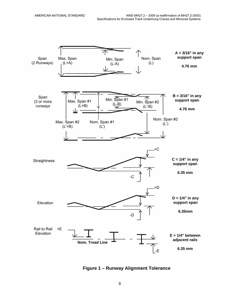
AMERICAN NATIONAL STANDARD ANSI MH27.2 – 2009 (a reaffirmation of MH27.2-2003) Specifications for Enclosed Track Underhung Cranes and Monorail Systems
Nom. Span (L)
Max. Span (L+A)
Min. Span (L-A)
A = 3/16" in any support span
4.76 mm
Max. Span #2 (L'+B)
Max. Span #1 (L+B)
Min. Span #1 (L-B) Min. Span #2
(L'-B)
Nom. Span #2 (L’) Nom. Span #1
(L')
Span (2 Runways)
B = 3/16" in any support span
4.76 mm
Span (3 or more runways
+C
-C
C = 1/4" in any support span
6.35 mm
Straightness
+D
-D
D = 1/4" in any support span
6.35mm
Elevation
Rail to Rail
Elevation +E
-E
Nom. Tread Line
E = 1/4" between adjacent rails
6.35 mm
Figure 1 – Runway Alignment Tolerance
9
AMERICAN NATIONAL STANDARD ANSI MH27.2 – 2009 (a reaffirmation of MH27.2-2003) Specifications for Enclosed Track Underhung Cranes and Monorail Systems
6.2.5 Lifted or live load impact factor This factor applies to powered hoists only and shall be included in the design of all components of the crane or monorail system. The impact factor should be 1/2% of the rated or working load for each foot per minute (1.6% of rated or working load for each meter per minute) of hoisting speed with minimum factor value of 15% and a maximum factor value of 50%. For vacuum and magnet applications, a factor value of 50% shall be used. Designs not in accordance with these standards may be specified.
6.2.6 Case 2 – Principal plus additional Loads Case 2 loading shall include Case 1 loadings plus applicable loadings such as:
a) operating wind load
b) operating lateral load 6.2.7 Operating wind load
Lateral load due to wind, when applicable or specified, shall be considered as an operating load of 5 pounds per square foot (24.4 kg/m²) of projected area unless higher wind forces are specified. Where multiple surfaces are exposed to the wind force, such as crane girder and auxiliary girder, and the horizontal distance between surfaces is greater than the depth of the member on the windward side, consideration shall be given to increasing the effective area exposed to the wind.
6.2.8 Operating lateral load
Lateral load due to any other forces as specified by the purchaser or determined by the manufacturer shall be considered as an operating load.
6.2.9 Case 3 – Case 1 or Case 2 plus Extraordinary Loads Case 3 loading shall include Case 1 or Case 2 loading plus applicable loadings such as:
a) stored wind load,
b) collision load, and
c) seismic load. 6.3 Stored wind load
Lateral load due to the maximum wind that the track and bridge is designed to withstand during an out-of-service condition.
6.3.1 Collision load
Load due to the inadvertent collision of two cranes or trolleys (carriers); or crane or trolley (carrier) and end stops or bumpers.
6.3.2 Seismic load
Load due to specific seismic conditions. If required, seismic accelerations to the track shall be in accordance with section 6.1 and shall be specified by the owner.
The allowable stress levels under conditions of these loadings shall be applied in accordance with section 6.3.5.
10
AMERICAN NATIONAL STANDARD ANSI MH27.2 – 2009 (a reaffirmation of MH27.2-2003) Specifications for Enclosed Track Underhung Cranes and Monorail Systems
6.3.3 The allowable stress in the track shall be limited by the loading case that is considered.
Case 1 and Case 2 loadings are considered operating conditions, while Case 3 loading is considered an extraordinary event. Under Case 3 conditions, the equipment is expected to withstand the loading conditions, however, may not be operational after the event occurs.
6.3.4 Allowable stress on the track for Case 1 loading in Enclosed Steel Track shall not exceed
60% of the minimum yield strength of the material used. Refer to the AISC Manual of Steel Construction for additional design considerations. The allowable stress in Enclosed Aluminum Track shall not exceed 9.5 ksi or 65.5MPа. Refer to the Aluminum Association Specification for Aluminum Structures for additional design considerations.
6.3.5 Allowable stress on the track for Case 2 loading in Enclosed Steel Track shall not exceed
66% of the minimum yield strength of the material used. Refer to the AISC Manual of Steel Construction for additional design considerations. The allowable stress in Enclosed Aluminum Track shall not exceed 9.5 ksi or 65.5MPа. Refer to the Aluminum Association Specification for Aluminum Structures for additional design considerations.
6.3.6 Allowable stress on the track for Case 3 loading in Enclosed Steel Track shall not exceed
75% of the minimum yield strength of the material used. Refer to the AISC Manual of Steel Construction for additional design considerations. The allowable stress in Enclosed Aluminum Track shall not exceed 9.5 ksi or 65.5MPа. Refer to the Aluminum Association Specification for Aluminum Structures for additional design considerations.
SECTION 7 – Suspension Fittings All necessary clamps, hanger rods, and other fittings from which a track is suspended shall be considered as part of the track system. Track hangers shall support the load resulting from the maximum loading condition. The allowable cross-sectional area for hanger rods shall be determined from the root area of the rod (minor diameter of threads. 7.1 Where the track is suspended from hanger rods, the track shall be braced laterally and
longitudinally according to the manufacturer's standards to prevent damaging lateral loads. 7.2 Where the track is suspended from hanger rods, means shall be provided to prevent the
hanger-rod nuts from backing off the rods. 7.3 Where multiple rods are used at a suspension point, consideration shall be given to the
unequal load induced in the rods. 7.4 In the design of hanger rods, the allowable stress shall be in accordance with AISC Manual
of Steel Construction. 7.5 The vertical tolerance for hanger rods shall depend on the manufacturer's standards. SECTION 8 – Carriers or Trolleys 8.1 Standard trolleys (carriers) for Enclosed Track shall be of the double axle type, and shall
provide for uniform loading of the track flange. 8.1.1 Non-metallic wheels shall have a minimum durometer of D74.
11
AMERICAN NATIONAL STANDARD ANSI MH27.2 – 2009 (a reaffirmation of MH27.2-2003) Specifications for Enclosed Track Underhung Cranes and Monorail Systems
8.1.2 Steel wheels shall not be used for load carrying devices in Enclosed Aluminum Track. 8.1.3 Wheel bearings shall be anti-friction precision type. Bearings shall be prelubricated and
sealed or provided with fittings and seals or shields for pressure lubrication. 8.1.3.1 Wheel bearings, applicable to "Duty Service Classification" as defined in Table 1, shall be
provided. 8.1.3.2 Bearing life shall be based on 75% of the wheel load (impact need not be included) and the
full-rated speed of motor-propelled carriers or an assumed speed of 150 FPM (46 meter per minute) for manually-propelled carriers.
8.2 Motor-propelled trolleys (carriers) should be driven by a driving head mounted on the load
bar of the load-carrying member with traction dependent on the wheel load of the driving heads, or by a tractor drive which provides traction by pressure of the driving wheel or wheels on the track. The pressure of the driving wheel or wheels on the tractor drive shall be adjustable.
8.2.1 All gearing shall be made from material of adequate strength and durability to meet the
requirements for the intended service class. 8.2.2 All gearing shall have adequate lubrication. 8.3 The wheelbase of trolleys (carriers) that operate on monorail systems with curves shall be
equal to or less than the radius of the smallest curve in the monorail system, not including curved track in switches.
SECTION 9 – Cranes, Transfer Cranes, and Interlocking Cranes 9.1 Cranes shall be manually or motor propelled, and operate on two or more runways. 9.1.1 Crane girders shall be designed in accordance with the provisions of Sections 5 and 6. 9.1.2 Standard trolley (carrier) for Enclosed Track shall be of the double axle type, and shall
provided for uniform loading of the track flange. 9.1.3 Wheels shall be in accordance with the provisions of Section 8.1.1. 9.1.4 Wheel bearings and bearing life shall be in accordance with the provisions of Sections
8.1.3, 8.1.3.1, and 8.1.3.2. 9.1.5 Lugs shall be provided on end trucks to limit drop of the end truck to 1" (25 mm) or less in
the event of wheel or axle failure. Lugs shall be located to provide central loading of the track about the vertical axis if failure occurs.
9.1.6 Ratio of crane span to end-truck wheelbase shall be as follows: 9.1.6.1 Where bridge girder is rigidly attached to the end truck and horizontal guide rollers prevent
skewing of the end truck, maximum ratio shall be 26:1. 9.1.6.2 Where bridge girder is pinned to the end truck and the crane is a push pull (manually
operated) type, maximum ratio shall be 105:1.
12
AMERICAN NATIONAL STANDARD ANSI MH27.2 – 2009 (a reaffirmation of MH27.2-2003) Specifications for Enclosed Track Underhung Cranes and Monorail Systems
9.1.7 Stops shall be provided at ends of girders in accordance with the provisions of Section 5.5. 9.1.8 Motor-propelled cranes shall be driven by individual driving heads or tractor drives mounted
on or attached to end trucks which provide traction by pressure of the driving wheels on the track. Drives shall be in accordance with the provisions of Sections 8.2, 8.2.1, and 8.2.2.
9.1.9 On double-girder cranes, means shall be provided to maintain the gauge of the girders. 9.1.10 Interlock mechanisms for transfer and interlocking cranes shall maintain alignment of crane
girder or girders with spur tracks, fixed transfer sections or crane girders of interlocking cranes operating on adjacent runways to permit the transfer of a carrier from one to the other.
9.1.10.1 Interlock mechanisms shall limit load-carrying flange misalignment to a maximum of 1/8" (3
mm). 9.1.10.2 Stops or forks shall be an integral part of the interlock mechanisms. When girders and
spur tracks or transfer sections are aligned and interlock mechanisms are engaged, stops or forks shall be in the open position and permit transfer of carrier from one to the other. When girders and spur tracks of transfer sections are not aligned and/or interlock mechanisms are disengaged, stops or forks shall be in the closed position and prevent carriers from rolling off the end of spur tracks, transfer sections, or crane girders.
9.1.10.3 Transfer and interlocking cranes, spur tracks, and fixed transfer sections shall have a
maximum gap of 1/8" (3 mm) between adjacent ends of the load-carrying flange. SECTION 10 – Track Switches 10.1 Track switches shall be of the tongue, rotary, or sliding type. They shall maintain alignment
of the incoming tracks and switch tracks, with a maximum gap of 1/16" (1.5 mm) between adjacent ends of the load-carrying flanges. Misalignment shall not exceed 1/16" (1.5 mm). Switches may be operated by mechanical-, electric-, pneumantic- or hydraulic-operated devices.
10.2 Stops shall be provided as an integral part of the switch to protect the end of an incoming
track when the switch track is not aligned with the incoming track, and shall resist the impact forces of a fully loaded trolley traveling at a normal walking speed or at 50% of the full-load speed, if the trolley is motor propelled. Guards shall also be provided to prevent a trolley (or carrier) on the movable track from running off the movable track, when it is not aligned with an incoming track.
10.3 Means shall be provided to hold the movable frame during passage of trolleys (or carriers)
through the track switch.
13
AMERICAN NATIONAL STANDARD ANSI MH27.2 – 2009 (a reaffirmation of MH27.2-2003) Specifications for Enclosed Track Underhung Cranes and Monorail Systems
SECTION 11 – Track Openers 11.1 Hand-operated or automatic track openers shall be provided where it is necessary to open
a section of track to allow for closing of sliding or curtain-type fire doors. These devices shall open the track and allow the door to close either by hand operation or as a result of the parting of a fuse in the event of a fire. The gap between the adjacent track and track opener shall be no more than 1/8" (3 mm) for enclosed track. Forks or stops designed per paragraph 5.5 shall be provided to prevent a trolley (or carrier) from running off either of the open ends of the track when the movable section is not in alignment with the track.
SECTION 12 – Vertical Drop or Lift Sections 12.1 Vertical drop or lift sections shall maintain alignment of the stationary track(s) and the
movable tracks(s) with a maximum gap of 1/8" (3 mm) for enclosed track, between adjacent ends of the load-carrying flanges.
12.2 When sections are operated by electric, pneumatic or hydraulic power, means shall be
provided to limit the vertical travel of alignment of the movable track with the stationary track(s). Misalignment between the movable track and stationary tracks shall not exceed 1/16" (1.5 mm).
12.3 Stops shall be an integral part of the movable track and shall prevent a trolley (carrier) from
running off either end of the movable track when the movable track is not in alignment with the stationary track(s). For enclosed track, the trolley (carrier) should be held centered in the movable track section prior to operation of this section.
12.4 Stops shall be an integral part of the stationary track(s) and shall prevent a trolley (carrier)
from running off the open ends of the stationary track(s) when the movable track is not in alignment with the stationary track(s).
12.5 Clearance should take into account the length of the load, hoist, and trolley (carrier). SECTION 13 – Cab-Controlled Carriers and Cranes (when provided) 13.1 Enclosed Track is not used in these applications. SECTION 14 – Brakes 14.1 Brakes supplied for carrier or crane travel may be applied by mechanical, electrical,
pneumatic, or hydraulic means. Brakes shall be in conformance with ASME B30.11 – Safety Standard for Monorails and Underhung Cranes.
14.2 Travel Holding Brakes, when provided, shall have a torque rating of at least 50% of the
rated motor torque and be adjustable to a minimum of 25% of the rated motor torque.
14
AMERICAN NATIONAL STANDARD ANSI MH27.2 – 2009 (a reaffirmation of MH27.2-2003) Specifications for Enclosed Track Underhung Cranes and Monorail Systems
SECTION 15 – Electrical Equipment 15.1 Wiring and equipment shall comply with the provisions of Article 610, ANSI/NFPA 70
National Electric Code. 15.2 The maximum voltage for the system power supply shall be 600 volts for alternating current
or 250 volts for direct current. The maximum control circuit voltage shall be 150 volts or A.C. or 300 volts for D.C.
15.3 Unless otherwise specified, all functions on floor-operated equipment shall be from a
common pendant pushbutton station. The pushbutton station shall be suspended in a manner that will protect the electrical conductors against strain. Motion controls shall return to the off position when released by the operator.
15.4 Motors shall be rated on no less than a 30 minute basis with temperature rise in accordance
with the latest NEMA standards for the class of insulation and enclosure. Designs not in accordance with these standards may be specified. Motors shall be of the type suitable for crane and hoist service and shall be provided with anti-friction bearings. Motor duty rating shall be suitable for the service class required.
15.5 Control systems may be magnetic, solid state, static, or in combination as specified. Crane
and carrier controls shall be plain reversing unless otherwise specified. All reversing contactors shall be mechanically and electrically interlocked. Unless otherwise specified, controls shall be mounted in NEMA type 1 general-purpose enclosures (see section 1.4 for special applications).
15.5.1 Magnetic control shall have contactors of sufficient size for crane and hoist duty consistent
with the horsepower and voltage of the motor or motors with which they are used. 15.5.2 Solid state power components such as thyristors, diodes, etc., shall be rated in accordance
with the horsepower, voltage and time ratings of the motor or motors with which they are used.
15.5.3 Trolleys (carriers) and cranes with squirrel cage motors and single speed control should be
provided with reduced torque starting through the use of solid state devices, autotransformers, resistors, fluid couplings, or electro-mechanical means.
15.5.4 Trolleys (carriers) and cranes with squirrel cage motors and multi-speed control should be
provided with reduced torque in starting and changing from one speed to the other. Reduced torque may be provided through the use of solid state devices, autotransformers, resistors, fluid couplings, or electro-mechanical means.
15.5.5 Trolleys (carriers) and cranes with squirrel cage motors that use variable frequency drives
with controlled acceleration and deceleration do not need reduced torque solid state devices, autotransformers, resistors, fluid couplings, or electro-mechanical means specified in sections 15.5.3 and 15.5.4.
15.5.6 Where more than one motor is employed on a crane, each motor shall have individual
phase overcurrent protection. Where two or more motors operate a single carrier or crane and are controlled as a unit by one controller, the motors with their leads may be protected by a single overcurrent device.
15
AMERICAN NATIONAL STANDARD ANSI MH27.2 – 2009 (a reaffirmation of MH27.2-2003) Specifications for Enclosed Track Underhung Cranes and Monorail Systems
15.6 A motor-circuit switch or circuit breaker shall be provided in the leads from the runway contact conductors on all electrically-powered cranes. Where this disconnecting means is not readily accessible from the crane operating station, means shall be provided at the crane operating station to open the power circuit to the crane motors, except as specified in Article 610 of ANSI/NFPA 70 National Electric Code. The continuous ampacity of the motor-circuit switch or circuit breaker shall be no less than 50% of the combined short-time ampacities of the motors, nor less than 75% of the sum of the short-time ampacities of the motors required for any single crane motion.
SECTION 16 – Electrification 16.1 Where electrical equipment operates on a system, power shall be supplied by means of
insulated contact conductors mounted parallel to the track. Conductors shall comply with the provisions of Article 610, ANSI/NFPA 70 National Electrical Code. Flexible cable may be used in lieu of rigid-type contact conductors.
16.2 Conductors shall be sized to carry the required current to the crane(s), when operating with
rated load. 16.3 Collectors shall be of the wheel or shoe type and shall be designed to minimize sparking
between the wheel or shoe and the contact conductor. SECTION 17 – Glossary 17.1 Ambient Temperature – The temperature of the atmosphere surrounding the equipment. 17.2 Ampacity – The current carrying capacity expressed in amperes. 17.3 Automatic Crane – A crane that when activated operates through a preset cycle or cycles. 17.4 Automatic Dispatch Carrier – A carrier that when activated operates through a preset
cycle or cycles. 17.5 Balancer – A suspended machinery unit that is used for lifting, lowering, or balancing a
freely suspended (unguided) load. 17.6 Bearing Life – B-10 Bearing Life – The B-10 bearing life of an anti-friction bearing is the
minimum expected life, in hours, of 90% of a group of bearings that are operated at a given speed and loading.
17.7 Bridge Travel (Crane Travel) – Crane movement in a direction parallel to the crane
runway. 17.8 Bridge Girder (Crane Girder) – Crane member on which carriers (trolleys) travel,
horizontally mounted between and supported by the end trucks. 17.9 Building Structure – The structural members of a building that support the building loads
and on which the loads of crane or monorail equipment, and the material to be moved, will be imposed.
16
AMERICAN NATIONAL STANDARD ANSI MH27.2 – 2009 (a reaffirmation of MH27.2-2003) Specifications for Enclosed Track Underhung Cranes and Monorail Systems
17.10 Brake – A device other than a motor used for retarding or stopping motion by friction or power means.
17.11 Cab – An operator's compartment attached to a crane or carrier. (Not applicable to
Enclosed Track). 17.12 Cab-controlled – Equipment controlled from an operator's cab. (Not applicable to
Enclosed Track). 17.13 Carrier – See Trolley. 17.14 Circuit Breaker – A device to open and close a circuit by non-automatic means, and to
open the circuit automatically on a predetermined overcurrent, without injury to itself when properly applied within its rating.
17.15 Clamp – A type of suspension fitting used to support tracks from an overhead structure,
which is fastened to the structure by mechanical means rather than welding or direct bolting.
17.16 Collectors – Electrical contacting devices providing a path for current flow from stationary
conductors to moving equipment. 17.17 Collector, Shoe – The portion of a collector that makes contact by sliding on the conductor
bar. 17.18 Collector, Wheel – The portion of a collector that makes contact by rolling on the conductor
bar. 17.19 Conductors, Insulated – A bar with a non-conducting cover material to minimize
accidental contact with the conductor, used to transmit an electrical current. 17.20 Control, Single Speed – A drive control system providing one-speed operation in either
direction. 17.21 Control, Multi-Speed – A drive control system providing more than one-speed operation in
either direction using multi-speed squirrel cage motors. 17.22 Control, Variable Speed – A drive control system providing more than one-speed
operation in either direction. 17.23 Control Voltage – The voltage impressed on the control devices. 17.24 Controller – A device by means of which the operator controls the speed, acceleration,
torque and/or direction or motor-driven equipment. 17.25 Crane – A machine for lifting and lowering a load, and moving it horizontally. Drives may
be manual, power, or a combination of both. 17.26 Crane Girder – See Bridge Girder. 17.27 Crossover (Fixed Transfer Section) – A connecting track with an interlock mechanism on
both ends, mounted between two interlocking cranes, used to transfer a carrier from one bridge girder to the other.
17
AMERICAN NATIONAL STANDARD ANSI MH27.2 – 2009 (a reaffirmation of MH27.2-2003) Specifications for Enclosed Track Underhung Cranes and Monorail Systems
17.28 Curves – Formed sections of track used to change the horizontal or vertical directions of carrier travel.
17.29 Disconnecting Means – A device, or group of devices, or other means whereby the
conductors of a circuit can be disconnected from their source of supply. 17.30 Double Girder Crane – A crane having two bridge girders mounted between and
supported from the end trucks. 17.31 Driving Head – A motor-driven carrier head which is supported from and propelled by the
load bearing wheels. 17.32 Drop Section (Lift Section) – A mechanism that will permit a section of track(s) to be lifted
or lowered out of alignment with the stationary track(s). 17.33 Electric Baffles – Conductors wired to cut off electric power to approaching motor-driven
equipment if track switches, drop sections, and other movable devices are not properly set for passage of equipment.
17.34 Electrically Interlocked – An electrical device that prevents a short circuit when opposite
controls are operated at the same time. 17.35 Electrification – The track mounted conductor system by which the moving equipment
receives its electrical power. 17.36 End Stop – A device located at the end of the track or crane bridge to prevent the carrier
from running off the end of the track or crane. 17.37 End Truck – An assembly consisting of the truck frame and wheels that supports the crane
girder(s) and allow movements along the runway. 17.38 Equipment Supplier – The supplier of monorail and/or underhung crane systems under
contract. 17.39 Fixed Cranes – Cranes that are non-mobile. Jib cranes are classified as fixed cranes. 17.40 Fixed Transfer Section - See Crossover. 17.41 Floor Controlled – Motor propelled units that are controlled by an operator on the floor by
means of pushbutton station suspended from the overhead equipment. 17.42 Fork – A pivoting mechanical end stop portion of an interlock. 17.43 Gantry Crane – A traveling crane similar to an overhead crane, except that the bridge for
carrying the hoisting mechanism is rigidly supported on two or more legs running on fixed rails or other runway.
17.44 Gauge – The center-to-center distance between the load-carrying flanges of the two crane
girders of a double girder crane. 17.45 Guard – A portion of a switch provided to prevent carriers from running off the open ends of
the switch tracks in the event the switch is moved with the carrier on the inner frame of the switch.
18
AMERICAN NATIONAL STANDARD ANSI MH27.2 – 2009 (a reaffirmation of MH27.2-2003) Specifications for Enclosed Track Underhung Cranes and Monorail Systems
17.46 Hanger Rod – Steel rods that, together with other fittings, are used to suspend the track from the supporting structure.
17.47 Hoist – A suspended machinery unit that is used for lifting or lowering a freely suspended
(unguided) load. 17.48 Holding Brake – A brake that automatically prevents motion when power is off. 17.49 Impact Allowance – Additional hook load assumed to result from the dynamic effect of the
live load. 17.50 Interlock Mechanism – A mechanical device to lock together the adjacent ends of two
cranes or a crane to a crossover or spur track to permit the transfer of carriers from one crane or track to the other.
17.51 Interlocking Crane – A crane with an interlock mechanism on one or both ends enabling it
to be mechanically locked to another crane, crossover, or spur track for the purpose of transferring a carrier from one to another.
17.52 Lift Section – See Drop Section. 17.53 Load – The total weight superimposed on the loadblock, hook, or trolley. 17.54 Load Bar – A load-carrying member between trolleys or trolley heads. 17.55 Load Block – The assembly of hook or shackle, swivel, bearing, sheaves, pins, and frame
suspended by the hoist rope or load chain. This shall include any appurtenances reeved in the hoisting rope or load chain.
17.56 Load-Carrying Flange – The lower flange of the track on which the load-bearing wheels
roll. 17.57 Lug – A mechanical device that is part of the truck/carrier frame, which will prevent the
crane end truck or trolley from falling on the event of a wheel or axle failure. 17.58 Magnet – An electromagnetic device carried on a hoist hook, used to pick up and carry
loads magnetically. 17.59 Master Switch – A device that controls the operation of contactors and auxiliary devices of
an electric circuit. 17.60 Mechanically Interlocked – A mechanical device that prevents operation of opposite
controls at the same time. 17.61 Monorail – A single run of overhead track on which trolleys (carriers) travel. 17.62 Motor Circuit Switch – A switch, rated in horsepower, capable of interrupting the
maximum operating overload current of a motor of the same horsepower rating as the switch at the rated voltage.
17.63 Normal Walking Speed – A walking speed assumed to be 150 FPM (46 meters per
minute). 17.64 Overhead Traveling Crane – A crane that follows a fixed path on elevated runways.
19
AMERICAN NATIONAL STANDARD ANSI MH27.2 – 2009 (a reaffirmation of MH27.2-2003) Specifications for Enclosed Track Underhung Cranes and Monorail Systems
17.65 Pulpit Controlled – A unit operated from a fixed operator station not attached to the crane. 17.66 Pushbutton Station – An electrical control device consisting of pushbutton-operated
contacts in an enclosure used by the operator for control of the powered motions of the crane, carrier, hoist, and other auxiliary equipment.
17.67 Qualified Person – A person, who by possession of a recognized degree in an applicable
field, or certificate of professional standing, or who by extensive knowledge, training, and experience, has successfully demonstrated the ability to solve or resolve problems relating to the subject matter and work.
17.68 Radio Controlled – A unit operated from a radio transmitter located at a point not
mechanically attached to the device being controlled. 17.69 Rated Load – The maximum load designated by the manufacturer or qualified person for
which the crane or monorail system is designed and built. 17.70 Remote Controlled – A unit operated from a control station located at a point not
mechanically attached to the device being controlled. 17.71 Residual Magnetism – The magnetic field remaining in a magnet after power has been
removed. 17.72 Rotary Switch – A track switch with a movable inner frame containing straight and/or curve
sections of track. The inner frame can be rotated around a vertical axis to align these tracks with other tracks for routing carriers from one track to another.
17.73 Runway – The track and support system upon which the crane travels. 17.74 Semi-Gantry Crane – A traveling crane with one end of the bridge supported on one or
more legs running on fixed rails or other runway and the other end of the bridge supported by a track running on an elevated fixed rail or runway.
17.75 Shall – Indicates that the rule is mandatory and must be followed to comply with this
standard. 17.76 Should – Indicates that the rule is a recommendation, the advisability of which depends on
the facts in each situation. 17.77 Simple Beam – A structural member supported and unrestrained at each end and
subjected to loads acting transversely to its longitudinal axis. 17.78 Sliding Switch (Glide Switch) – A track switch with a movable inner frame containing
straight and/or curved sections of track. The inner frame can be moved to align these sections of track with other tracks for routing carriers from one track to another.
17.79 Span – The horizontal distance, center-to-center, of runway tracks. 17.80 Splices – Mechanical devices used to join the adjacent end of track sections. 17.81 Spur Track – A fixed track arranged to interlock with an adjacent crane girder to permit
passage of carriers between the spur track and the crane. 17.82 Squaring Shaft – A driven shaft that transmits torque to drive wheels operating on two or
more tracks.
20
AMERICAN NATIONAL STANDARD ANSI MH27.2 – 2009 (a reaffirmation of MH27.2-2003) Specifications for Enclosed Track Underhung Cranes and Monorail Systems
17.83 Stationary Track – A fixed track attached to the building or supporting structure. 17.84 Stop – A device to limit travel of a carrier (trolley) or crane. 17.85 Structural Supports – Structural members provided for the support of runways or monorail
track and switches. 17.86 Supporting Structure – The structure used for the support of a monorail or crane system. 17.87 Suspension Fittings – Fittings used to attach the track to the supporting structure. 17.88 Tagline – An electrical conductor system employing flexible cables. 17.89 Tongue Switch – A switch that contains one straight section of track, pivoted at one end,
which can be rotated to various positions to align with other tracks for routing trolleys (carriers) from one track to another.
17.90 Track – The structural member upon which the carrier or crane wheels operate. 17.91 Track, Enclosed – A generic term referring to track used as crane girders, crane runways,
and monorails; whose related equipment operates on the internal lower operating or running flange of such track. The track section is either a rolled and/or fabricated steel shape; or a rolled or extruded and/or fabricated aluminum shape. All enclosed track incorporates a lower operating or running flange shape, in relation to track size, having proprietary shape dimensions dependent upon the individual enclosed track manufacturer.
17.92 Track, Patented – A generic term referring to track used as crane girders, crane runways,
and monorails; whose related equipment operates on the external lower operating or running flange of such track. The track section is either a high-carbon, high-manganese rolled steel shape; or a composite fabricated steel section having a high-carbon, high-manganese rolled steel tee-section lower operating or running flange. All patented track, regardless of size or depth, incorporates a lower operating or running flange shape, having proprietary shape dimensions dependent upon the individual patented track manufacturer.
17.93 Track Joint – The point at which two sections of track are joined together. 17.94 Track Opener – A section of track arranged to lift or swing out of the line of the track to
make an opening through which a door may pass. 17.95 Tractor Drive – A motor-driven unit supported from wheels and propelled by drive wheel or
wheels bearing on the underside of the track. 17.96 Trolley – A unit that travels on the running flange of a monorail track or bridge girder used
to support and transport a load. 17.97 Turntable – A track device with a movable inner frame containing a straight section of track
that can be rotated about its center with a loaded carrier on it to align the section of track with other tracks for routing of carriers from one track to another.
17.98 Underhung Crane – A traveling crane with a movable bridge running on the lower flanges
of an overhead fixed runway structure and carrying a movable or fixed hoisting mechanism.
17.99 Wall Crane – A traveling crane having a jib with a movable or fixed hoisting mechanism and operating on a runway attached to the side walls or columns of a building.
21