SPECIFICATIONS AND STANDARD DRAWINGS Lift... · Typical Lift Station Detail - Wet Well Exterior...
41
SEWER LIFT STATION SPECIFICATIONS AND STANDARD DRAWINGS ENGINEERING DIVISION 33 EAST BROADWAY AVENUE, SUITE 200 MERIDIAN, ID 83642 July 2018
Transcript of SPECIFICATIONS AND STANDARD DRAWINGS Lift... · Typical Lift Station Detail - Wet Well Exterior...
SEWER LIFT STATION SPECIFICATIONS
AND STANDARD DRAWINGS
ENGINEERING DIVISION 33 EAST BROADWAY AVENUE, SUITE 200
MERIDIAN, ID 83642
July 2018

TABLE OF CONTENTS
PREFACE
CITY ENGINEER’S LETTER
SECTION 512 - SEWER LIFT STATION CONSTRUCTION
PART 1 - GENERAL
1.1 Section Includes …………………………………………………………… 1
1.2 Related ISPWC Divisions …………………………………………………… 1
1.3 References …………………………………………………………… 2
1.4 Submittals …………………………………………………………… 2
1.5 Project Record Documents …………………………………………………... 3
1.6 Permits, Fees, and Inspections …………………………………………… 4
PART 2 - MATERIALS
2.1 Wet Well …………………………………………………………………… 4
2.2 Discharge Manhole …………………………………………………………… 5
2.3 Access Doors …………………………………………………………………… 5
2.4 Pumps …………………………………………………………………… 6
2.5 Submersible Chopper Pump …………………………………………………… 7
2.6 Pumping System Components …………………………………………… 9
2.7 Pipe and Fittings …………………………………………………………… 10
2.8 Valves …………………………………………………………………… 10
2.9 Locating Tape …………………………………………………………………… 11
PART 3 – WORKMANSHIP
3.1 Wet Well …………………………………………………………………… 11
3.2 Discharge Manhole …………………………………………………………… 11
3.3 Access Doors …………………………………………………………………… 12
3.4 Pumps …………………………………………………………………… 12
SECTION 512A - Electrical
PART 1 - GENERAL
1.1 Section Includes …………………………………………………………… 13
1.2 Standards and References …………………………………………………… 13
1.3 Testing …………………………………………………………………… 13
1.4 Miscellaneous …………………………………………………………………… 14
PART 2 - MATERIALS
2.1 Service Entrance and Equipment …………………………………………… 15
2.2 Control Panel …………………………………………………………………… 15
2.3 Flow Meter …………………………………………………………………… 16
2.4 Conduit Conductors …………………………………………………………… 17
2.5 Conductors …………………………………………………………………… 17
2.6 Locating Tape …………………………………………………………… 17

TABLE OF CONTENTS (continued)
PART 3 - WORKMANSHIP
3.1 Service Entrance and Equipment ……………………………………………. 17
3.2 Control Panel ……………………………………………………………………. 18
3.3 Conduit ……………………………………………………………………. 18
3.4 Conductors ……………………………………………………………………. 18
3.5 Supervisory Control and Data Acquisition – SCADA ……………………. 19
SECTION 512B – SITE IMPROVEMENTS
PART 1 - GENERAL
1.1 Section Includes ……………………………………………………………. 20
PART 2 - MATERIALS
2.1 Fencing ……………………………………………………………………. 20
2.2 Lighting ……………………………………………………………………. 21
2.3 Gravel Access Road and Interior Area ……………………………………. 21
2.4 Yard Hydrant ……………………………………………………………………. 21
PART 3 – WORKMANSHIP
3.1 Fencing ……………………………………………………………………. 21
3.2 Gravel Access Road and Interior Area ……………………………………. 22
3.3 Yard Hydrant ……………………………………………………………………. 22
3.4 Landscaping ……………………………………………………………………. 22
SECTION 512C – COMPLETION REQUIREMENTS
1.1 Final Cleaning ……………………………………………………………. 23
1.2 Adjustments ……………………………………………………………………. 23
1.3 Operation and Maintenance Data ……………………………………………. 23
1.4 Warranties ……………………………………………………………………. 24
1.5 Spare Part and Maintenance Materials ……………………………………. 25
1.6 Statement of Compliance ……………………………………………………. 25
SECTION 512D – SYSTEM START UP
1.1 General ……………………………………………………………………. 26
1.2 Demonstration and Instruction ……………………………………………. 26
SECTION 512E – OFF PEAK PUMPING STATIONS
1.1 General Requirements ……………………………………………………. 28
1.2 Leniencies ……………………………………………………………………. 28

INDEX OF STANDARD DRAWINGS
SEWER LIFT STATION DRAWINGS
LS1 …. Lift Station Notes
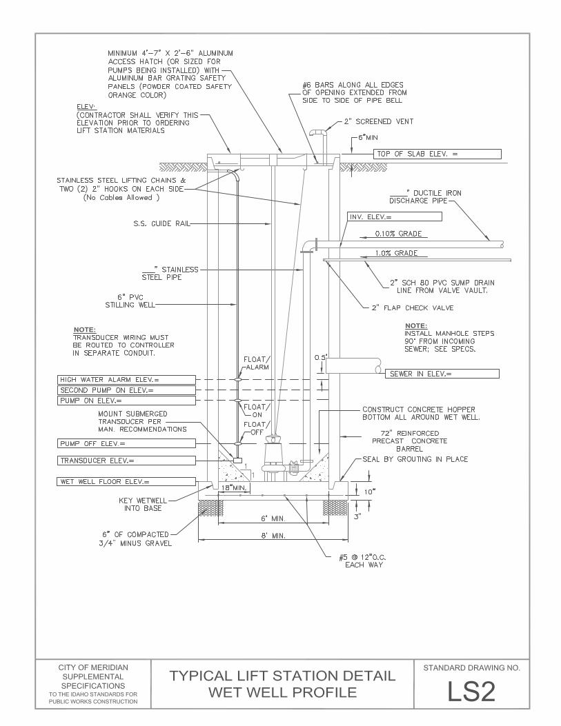
LS2 …. Typical Lift Station Detail - Wet Well Profile
LS3 …. Typical Lift Station Detail - Wet Well Exterior Piping
LS4 …. Typical Lift Station Detail - Control Panel Layout
LS5 …. Typical Lift Station Detail - One Line Diagram
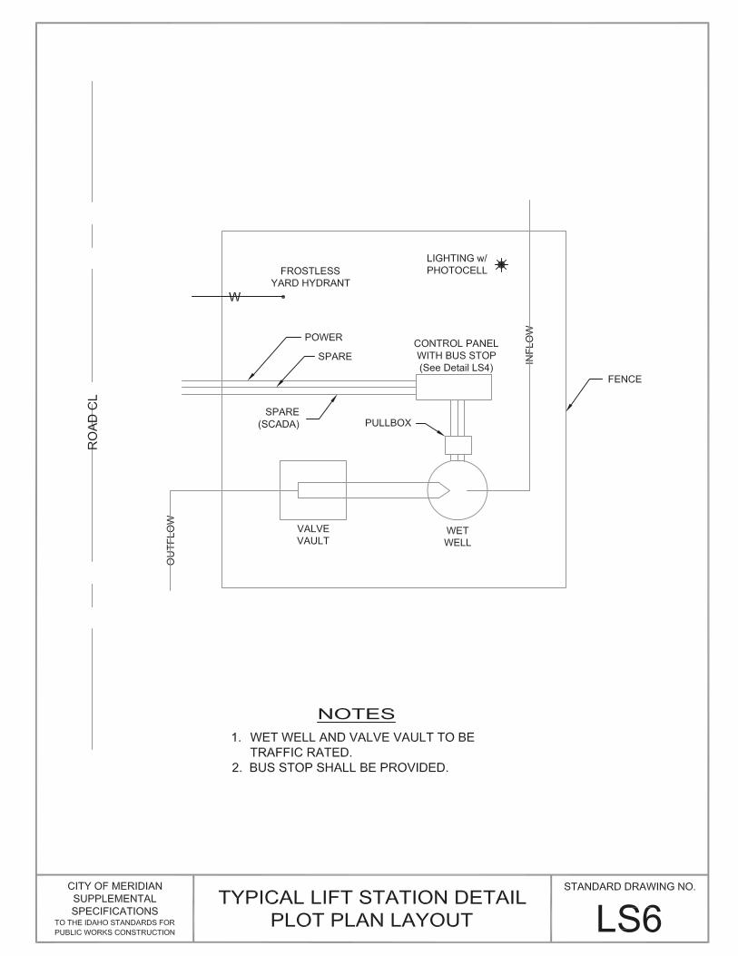
LS6 …. Typical Lift Station Detail – Plot Plan Layout

PREFACE
These Sewer Lift Station Specifications and Drawings are intended to supplement the current
edition of the Idaho Standards for Public Works Construction (ISPWC) and the City of Meridian
Supplemental Specifications and Standard Drawings. In instances where the ISPWC does not
clearly provide for additional requirement(s) of the City of Meridian, these specifications shall be
used.
All construction within the City of Meridian, or within the jurisdiction of the City of Meridian,
shall be completed in accordance with the ISPWC, the City of Meridian Supplemental
Specifications and Standard Drawings, the approved Construction Plans, all applicable State,
Federal, County and local district regulations and Specifications; and in compliance with the City
of Meridian Subdivision Ordinance. The more stringent of any of these standards shall be the
controlling standards or specifications. The City of Meridian recognizes that the ISPWC and the
City of Meridian Supplemental Specifications may not cover all situations that might be
encountered; however, this does not release the Contractor from properly constructing the work.
Any supplemental specification that the City Engineer or a designated representative deems
necessary for the proper construction of any work shall be prepared and issued to the Contractor
prior to commencing construction.


Page 1 of 29 SECTION 512
CONSTRUCTION
SECTION 512
CONSTRUCTION
PART 1 - GENERAL
1.1 SECTION INCLUDES
A. This section covers duplex lift stations which have a single pumping capacity that
meets one of the following criteria:
1. 400 gallons per minute or less.
2. Projected peak inflow of less than 0.8 CFS.
3. Approximately 500 equivalent residential units (ERU’s).
B. Lift stations with unique site characteristics may be required to meet additional
requirements not contained in this specification. Some examples are as follows:
1. Exceptional depth.
2. Pumping into gravity sewer served by another existing lift station.
3. Wide range of initial and ultimate inflows.
4. Larger lift stations may be subject to additional requirements not included
in this section.
C. Lift stations shall comply with City of Meridian Standard Drawings LS1 through
LS6.
1.2 Related DIVISIONS of the ISPWC & City of Meridian Supplemental Specifications
A. Division 300 - Trenching
B. Division 400 - Water
C. Division 500 – Sewer
D. Division 700 – Concrete
E. Division 2000 – Miscellaneous

Page 2 of 29 SECTION 512
CONSTRUCTION
1.3 REFERENCES
A. All references listed in the ISPWC for Divisions shown in Item 1.2 above are
applicable to Lift Station construction.
B. If there is any conflict between these specifications or drawings and any local,
state or federal code, standard or requirement, the codes, rules and regulations
shall take precedence.
1.4 SUBMITTALS
In addition to subdivision development plan approval, preliminary equipment submittals
must be approved by the Public Works Department, prior to construction. The submittals
shall include, at a minimum, the following:
A. Lift Station Design Drawings including:
1. Site Plans depicting plan, elevation and section views.
a. All proposed structures.
b. Mechanical Plans (including HVAC Fans)
c. All electrical components.
d. All electrical control diagrams.
C. Proposed landscaping plans.
D. Design criteria and calculations including:
1. Initial and ultimate service area flows (in coordination with Public Works)
2. Wet well volume, basis for sizing:
a. Five (5) pump starts per hour maximum per pump.
b. One hour emergency storage above high water alarm, and below
incoming gravity sewer invert, at peak effluent inflow.
c. Maximum fill time at average design flow less than 30 minutes.

Page 3 of 29 SECTION 512
CONSTRUCTION
3. Pump and pressure main sizing including system curves for initial pump
installation and ultimate size pumps. Minimum pressure main size is four
(4) inch diameter. Minimum velocity at design pump rate is 2 feet per
second.
4. Uplift or buoyancy potential of wet well. The minimum factor of safety
is 2.0.
C. Catalog cut sheets
1. Structures.
2. Pumps and related appurtenances.
3. Electrical Components.
4. Fencing Materials.
D. Other Agencies
1. Lift stations that will become a part of the City of Meridian wastewater
collection system must be approved by the Idaho Department of Environment
Quality prior to construction. DEQ may have additional requirements not
contained in these specifications. The engineer of any proposed lift station
should consult with DEQ and obtain their Wastewater Pump Station Checklist
prior to design.
1.5 PROJECT RECORD DOCUMENTS
A. Maintain on site, one (1) set of the following documents, which shall show all
recorded measurements (Per Item 1.4, B. of this section.) that vary from the
approved plans:
1. Contract Drawings.
2. Specifications.
3. Addenda.
4. Change Orders and other Modifications to the Contract.
5. Reviewed shop drawings, product date, and samples.

Page 4 of 29 SECTION 512
CONSTRUCTION
B. Record Documents and Shop Drawings shall show actual construction of the
following items (as a minimum):
1. Measured depths of foundations in relation to finish floor datum.
2. Measured horizontal and vertical locations of underground utilities and
appurtenances referred to permanent surface improvements.
3. Measured locations of internal utilities and appurtenances concealed in
construction, referenced to visible and accessible features of the work.
4. Field changes of dimension and detail.
5. Details not on original approved Contract Drawings.
6. Product substitutions or alternates utilized.
Submit a CD and hardcopy of Final record drawings, O&M Manuals and other
documents to Design Engineer and Public Works Department with written request for
final approval and acceptance.
1.6 PERMITS, FEES, AND INSPECTIONS
A. The Developer shall obtain and pay for all required permits, fees and inspections
in connection with this work.
PART 2 - MATERIALS
2.1 WET WELL
A. The wet well shall consist of the following components:
1. Minimum 72-inch diameter pre-cast concrete manhole base and barrel
sections.
2. Lid shall be ASTM A-48; HS-25 load rating, hatches shall include
aluminum bar grating safety panels (powder coated, safety orange color).
3. Interior steps must meet or exceed ASTM C-478, AASHTO M-199 and
other applicable OSHA requirements.

Page 5 of 29 SECTION 512
CONSTRUCTION
4. A pressure transducer, KPSI, MODEL 750 (scaled to 15 psi), shall be
installed in the wet well (for monitoring of the wet well liquid levels). It
shall be self-cleaning, maintenance free, FM approved for Class I, DIV 1,
A, B, C, D hazardous locations. It shall be supplied with a minimum of
forty (40) feet of cable for connection to the microprocessor located in the
pump control panel.
5. A high level float shall be installed in the wet well programmed to run
applicable VFDs with a low level float shutoff.
6. All interior fasteners, anchors, and miscellaneous hardware shall be
stainless steel.
7. Flow meter
a. The flow meter shall be a magnetic flow meter with 150lb. flanges,
316 stainless steel self-cleaning electrodes, be compatible with
wastewater and have the ability to be submerged underwater. The
device must have the ability to read GPM and total gallons pumped on
a display in the swing out panel. It must be compatible with the city’s
SCADA system.
2.2 DISCHARGE MANHOLE
A. The discharge manhole shall be constructed in accordance with the Meridian
Supplemental Specifications; Division 500, Section 502.
2.3 ACCESS DOORS
A. Wet Well, Valve Vault and Flowmeter Vault Access Doors and Frame.
1. The frame and door shall be aluminum with mill finish and shall be
capable of supporting a live load of 300 pounds per square foot, with a
deflection of the door not to exceed 1/180th of the span. It shall include an
aluminum bar grating safety panel (powder coated, safety orange color)
where applicable.
2. The frame shall include accessories for attachment of the stainless steel
pump removal guide rails and must have attached anchor rods to secure its
placement in the concrete cover. The exterior surfaces of the aluminum
frame shall be coated with bituminous coating where it comes in contact
with concrete.
3. The aluminum cover must be equipped with a hasp lock to accept the lock
standard to the Wastewater Division.

Page 6 of 29 SECTION 512
CONSTRUCTION
2.4 PUMPS
A. Must have a duplex pumping arrangement with a backup pump for redundancy.
B. Must be explosion-proof and capable of producing 110% of the projected peak
flow generated by its service area.
C. Must operate on three phase power (if available), with a minimum of single phase
230 volt, 60 Hz.
D. Variable frequency drives (VFD); preferred.
E. Must be submersible, chopper, capable of passing three-inch solids.
F. Carrier-sealing flange, base plate-elbow and single rail (stainless steel) guide
assembly must be supplied by the pump manufacturer.
G. Pump lifting chain with w/ 4-inch (minimum) diameter stainless steel connecting
ring to pump (cables not allowed).
H. Must contain an identifying, attached tag showing manufacturer's name, model
number and rating/capacity.
Submersible Chopper pumps outlined in section 2.5 are preferred for use in the
sewer lift stations to be maintained by the City of Meridian. Other manufacturers
may be considered with the approval of the City Engineer if they substantially
conform to the requirements listed in this specification. Such proposals must
include the following submittals as a minimum for consideration:
1. Complete manufacturer’s literature.
2. Exceptions to the specifications listed herein.
3. Location of nearest service facility.
Alternates shall be pre-approved no less than 15 days prior to the bid date,
accompanied by a list of no less than twenty five (25) reference installations of
chopper pumps in identical service applications. At least five (5) of the reference
installations provided shall be of the exact model pump specified herein.
References shall be pumps that have been used in continuous service for a period
of no less than three (3) years. Only equipment that is in service at the time of
referral shall be considered valid. Pumps that have been removed from service
for any reason will not be considered as references. Telephone numbers and
contact names shall be provided for any/all references upon request from the City
Engineer. Provision of performance bonds or other means of circumventing the
above requirements for historical references and verification of past performance
in identical applications are not considered an acceptable means of verifying the
manufacturers' experience.

Page 7 of 29 SECTION 512
CONSTRUCTION
Review and approval must occur prior to development plan approval. No
substitutions will be considered after the Public Works Department review and
approval of the development plans.
2.5 SUBMERSIBLE CHOPPER PUMP
A. Where required by Meridian, the following are the detail specifications for the
Submersible Chopper Pumps.
B. Description: The vendor shall furnish two (2) Vaughan Model SE4l-075
submersible wet pit chopper pumps and all appurtenances as specified herein. The
pump shall be specifically designed to pump waste solids at heavy consistencies
without plugging or dewatering of the solids. Materials shall be
chopped/macerated and conditioned by the pump as an integral part of the
pumping action. The pump must have demonstrated the ability to chop through
and pump high concentrations of solids such as plastics, heavy rags, grease and
hair balls, wood, paper products and stringy materials without plugging, both in
tests and field applications.
C. Quality Assurance and Performance Affidavit: The warranty for workmanship
and materials shall be two (2) year from startup and acceptance by the owner. In
the performance affidavit, the manufacturer must certify to the Contractor and the
owner that the contract documents have been examined, and that the equipment
will meet in every way the performance requirements set forth in the contract
documents for the application specified. Shop drawings will not be reviewed
prior to the receipt by the engineer of an acceptable performance affidavit. The
performance affidavit must be signed by an officer of the company manufacturing
the equipment and witnessed by a notary public. The performance affidavit must
include a statement that the equipment will not clog or bind on solids typically
found in the application set forth.
D. Approved Manufacturer
1. Pump shall be Model SE4l-075 as manufactured by Vaughan Co., Inc.
2. It is the express intent of these specifications to accurately describe
equipment that is a regular production item of the specified manufacturer,
and that has a proven record of performance in identical (not just similar)
applications in other treatment facilities. The chopper pump manufacturer
shall have a minimum of twenty (20) years of documented experience in
the design and production of chopper pumps of all types, and not less than
five (5) years of experience in the production of the exact equipment as
specified herein.
E. Service Conditions: The pumps specified in this section will pump municipal
sewage. Each pump shall be capable of pumping 110% of the projected peak flow
generated by its service area.

Page 8 of 29 SECTION 512
CONSTRUCTION
F. Pump Construction
1. Casing and back pull-out adapter plate: The pump casing shall be of semi-
concentric design, with the first half of the circumference being cylindrical
beginning after the pump outlet, and the remaining circumference
spiraling outward to the 150 lb. flanged centerline discharge. Back pull-
out adapter plate shall allow removal of pump components from above the
casing, and allow external adjustment of impeller-to-cutter bar clearance.
Casing and adapter plate shall be ductile cast iron with all water passages
to be smooth, and free of blowholes and imperfections for good flow
characteristics.
2. Impeller: Shall be semi-open type with pump out vanes to reduce seal
area pressure. Chopping/maceration of materials shall be accomplished by
the action of the cupped and sharpened leading edges of the impeller
blades moving across the cutter bar at the intake openings, with a set
clearance between the impeller and cutter bar of .010" to .015". Impeller
shall be cast steel heat treated to minimum rockwell c 60 and dynamically
balanced. The impeller shall be keyed to the shaft and shall have no axial
adjustments or set screws required.
3. Cutter bar plate: Shall be recessed into the pump bowl and shall contain at
least 2 shear bars extending diametrically across the intake opening to
within 0.010-0.015" of the rotating cutter nut tooth, for the purpose of
preventing intake opening blockage and wrapping of debris at the shaft
area. Chopper pumps utilizing individually mounted shear bars shall not
be acceptable. Cutter bar shall be t1 plate steel heat-treated to minimum
Rockwell C 60.
4. Cutter nut: The impeller shall be secured to the shaft using a special cutter
nut, designed to cut stringy materials and prevent binding. The cutter nut
shall ASTM a148 cast alloy steel heat treated to minimum Rockwell C 60.
5. Upper cutter: Shall be threaded into the back pull-out adapter plate above
the impeller, designed to cut against the pump-out vanes and the impeller
hub, reducing and removing stringy materials from the mechanical seal
area. Upper cutter shall be cast steel heat treated to minimum Rockwell C
60.
6. Shafting: Type 420 stainless steel, or 1045 carbon steel with type 420
stainless steel sleeve. Pump shafting shall be heat treated. The pump shaft
shall directly couple to the motor shaft, with a bolt and keyway.
7. Seal: Mechanical seal shall be tandem mechanical seals in oil bath with
dual moisture sensing probes. Lower mechanical seal shall be alloy 20
welded metal bellows type with silicon carbide faces. Seal shall be
positively driven by set screws. Elastomers shall be of buna, and

Page 9 of 29 SECTION 512
CONSTRUCTION
stationary seal member shall be of the cup-mounted type to ensure
cushioning of face material from mechanical shock.
8. Stainless steel nameplates: Shall be attached to the pump and drive motor
giving the manufacturer's model and serial number, rated capacity, head,
speed and all pertinent data. If extra identification tags are supplied, one
shall be attached inside the control panel box.
G. Submersible Electrical Motor: The submersible motor shall be UL listed
explosion proof for class 1, group d, division 1 hazardous locations, rated as
required, 1750 rpm, 208 volts, 60 hertz and 3 phase, with a 1.15 service factor
(1.0 for continuous in-air) and class f insulation. Motor shall be equipped with
tandem mechanical seals in oil bath and dual moisture sensing probes. Motor
shall include two normally closed automatic resetting thermostats connected in
series and imbedded in adjoining phases. Motor frame shall be cast iron, and all
hardware and shaft shall be stainless steel.
H. Guide Rail System: The pumps shall be equipped with guide rail hardware and
connecting hardware for ease of installation/removal in the wet well.
I. Surface Preparation: SSPC-SP5 commercial sandblast, primed and finish coated
with minimum 6 MDFT 316 stainless steel pigment epoxy.
J. Review and approval of pumps must occur prior to development plan approval.
No substitutions will be considered after Public Works Department review and
approval of the development plans.
2.6 PUMPING SYSTEM COMPONENTS
A. Supports and Anchors
1. All pipe, other supports and anchors, lifting chains, excepting the supports
integral with the pump and base plate-elbow, shall be stainless steel.
B. Sleeves
1. Where piping penetrates the wall or ceiling of the wet well or valve vault,
the space between the pipe and adjacent surface shall be closed off with a
watertight flexible connector. The connector shall be Kor-N-Seal® as
manufactured by NPC, Inc., Milford, New Hampshire, or approved equal.
No adhesives or lubricants shall be employed in the installation of the
connector. The rubber for the connector shall comply with ASTM C443
and ASTM C923 and consist of EPDM and elastomers designed to be
resistant to the corrosive atmosphere of a pumped effluent environment.
Page 10 of 29 SECTION 512
CONSTRUCTION
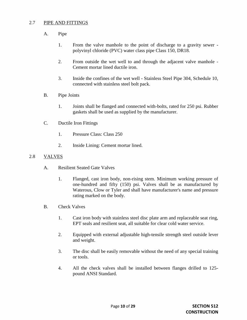
2.7 PIPE AND FITTINGS
A. Pipe
1. From the valve manhole to the point of discharge to a gravity sewer -
polyvinyl chloride (PVC) water class pipe Class 150, DR18.
2. From outside the wet well to and through the adjacent valve manhole -
Cement mortar lined ductile iron.
3. Inside the confines of the wet well - Stainless Steel Pipe 304, Schedule 10,
connected with stainless steel bolt pack.
B. Pipe Joints
1. Joints shall be flanged and connected with-bolts, rated for 250 psi. Rubber
gaskets shall be used as supplied by the manufacturer.
C. Ductile Iron Fittings
1. Pressure Class: Class 250
2. Inside Lining: Cement mortar lined.
2.8 VALVES
A. Resilient Seated Gate Valves
1. Flanged, cast iron body, non-rising stem. Minimum working pressure of
one-hundred and fifty (150) psi. Valves shall be as manufactured by
Waterous, Clow or Tyler and shall have manufacturer's name and pressure
rating marked on the body.
B. Check Valves
1. Cast iron body with stainless steel disc plate arm and replaceable seat ring,
EPT seals and resilient seat, all suitable for clear cold water service.
2. Equipped with external adjustable high-tensile strength steel outside lever
and weight.
3. The disc shall be easily removable without the need of any special training
or tools.
4. All the check valves shall be installed between flanges drilled to 125-
pound ANSI Standard.

Page 11 of 29 SECTION 512
CONSTRUCTION
5. The check valves shall be Clow Style F-5382, Kennedy Figure 106W; or
approved equal by the City Engineer.
C. Air and Vacuum Relief Valves
1. May be required depending on project specific design. Combination
air/vacuum valves shall be manufactured by Val-matic or approved equal.
2.9 LOCATING TAPE
A. Material: Two inch green 4 mil polyethylene.
B. Labeling: “Caution – Buried Sewer Line Below” in 1 ½-inch minimum black
lettering.
PART 3 - WORKMANSHIP
Installation requirements of all items not addressed in this section shall be accomplished by
either the manufacturer’s instructions, applicable codes, the Divisions of the ISPWC or the
Meridian City Supplemental Specifications.
3.1 WET WELL
A. The entire wet well shall be coated, prior to exposure of any effluent, with a
smooth coating of Elastomeric Polyurethane, 100% Solids, ASTM D16, Type V
or prior approved equal.
B. All electrical equipment in the wet well must meet National Electrical Code
(NEC) for Class I, Group D, Division 1 locations and be suitable for corrosive
conditions.
C. Flow meter will be installed in an additional vault downstream from the valve
vault.
3.2 DISCHARGE MANHOLE
A. The discharge manhole must be installed upstream of the gravity sewer.
B. Discharge will not be allowed into existing manholes.
C. Effluent shall flow from the discharge manhole to the gravity sewer by an
appropriately sized sewer pipe.
D. The discharge manhole shall be smoothly coated (prior to discharge of any
effluent into the manhole) with Strong Seal Sewper Coat®, or prior approved
equal.

Page 12 of 29 SECTION 512
CONSTRUCTION
3.3 ACCESS DOORS
A. The Contractor shall:
1. Submit shop drawings showing the exact location of all access units and
complete product data.
2. Verify that rough openings for the door and frame are correctly sized and
located, if not cast into the concrete cover.
3. Install units in accordance with the manufacturer's instructions.
4. Install frames level and secure rigidly in place.
5. Position frames to provide convenient access to the concealed work
requiring access.
3.4 PUMPS
A. Installation shall be in strict accordance with the manufacturer's instructions and
recommendations.
B. The pump shall operate at the specified system fluid temperature without vapor
binding and cavitation, is non-overloading in operation and operates within
twenty-five (25) percent of the midpoint of the published maximum efficiency
curve.
C. The piping adjacent to the pumps shall be supported such that no weight is carried
on the pump casings. The Contractor shall align the pump and piping prior to start
up.
END OF SECTION
Page 13 of 29 SECTION 512A
ELECTRICAL
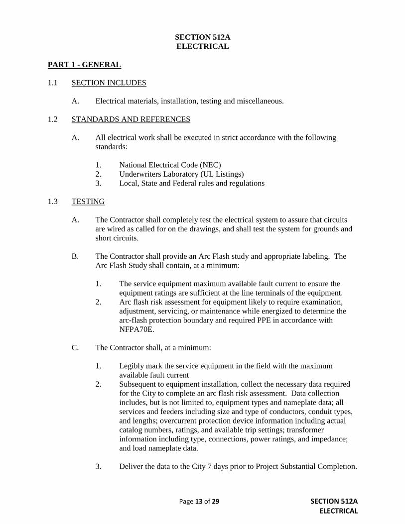
SECTION 512A
ELECTRICAL
PART 1 - GENERAL
1.1 SECTION INCLUDES
A. Electrical materials, installation, testing and miscellaneous.
1.2 STANDARDS AND REFERENCES
A. All electrical work shall be executed in strict accordance with the following
standards:
1. National Electrical Code (NEC)
2. Underwriters Laboratory (UL Listings)
3. Local, State and Federal rules and regulations
1.3 TESTING
A. The Contractor shall completely test the electrical system to assure that circuits
are wired as called for on the drawings, and shall test the system for grounds and
short circuits.
B. The Contractor shall provide an Arc Flash study and appropriate labeling. The
Arc Flash Study shall contain, at a minimum:
1. The service equipment maximum available fault current to ensure the
equipment ratings are sufficient at the line terminals of the equipment.
2. Arc flash risk assessment for equipment likely to require examination,
adjustment, servicing, or maintenance while energized to determine the
arc-flash protection boundary and required PPE in accordance with
NFPA70E.
C. The Contractor shall, at a minimum:
1. Legibly mark the service equipment in the field with the maximum
available fault current
2. Subsequent to equipment installation, collect the necessary data required
for the City to complete an arc flash risk assessment. Data collection
includes, but is not limited to, equipment types and nameplate data; all
services and feeders including size and type of conductors, conduit types,
and lengths; overcurrent protection device information including actual
catalog numbers, ratings, and available trip settings; transformer
information including type, connections, power ratings, and impedance;
and load nameplate data.
3. Deliver the data to the City 7 days prior to Project Substantial Completion.

Page 14 of 29 SECTION 512A ELECTRICAL
4. Initially set protective devices to maximum settings during equipment
installation, or as recommended by manufacturer.
5. Adjust protective device settings based on Arc Flash study results prior to
Project Substantial Completion.
6. Install arc flash warning labels marked with the incident energy level of
PPE from Arc Flash study on the outside of the electrical equipment
enclosures prior to substantial completion.
1.4 MISCELLANEOUS
A. Provide storage for materials and assume complete responsibility for losses.
Protect completed work, work underway and materials against loss or damage.
Close circuit openings with caps or plugs during installation. Cover fixtures and
equipment and protect against dirt or damage caused by water, chemicals or
mechanical accident.
B. The Contractor shall coordinate the work under this section with the work being
done under other sections. The Contractor shall promptly notify the Design
Engineer of any conflicts within the Plans and Specifications. All changes
required in the work of the Contractor as a result of his failure to notify the
Design Engineer shall be made by the Contractor at his own expense.
C. The developer and/or Contractor shall coordinate with the telephone company as
to the termination point at the property line of a black one (1) inch PVC, with pull
wire, for their service.
D. The developer and/or Contractor shall coordinate with the power company for
permanent power service and, if necessary, temporary power. The developer
and/or Contractor shall be solely responsible for any and all costs associated with
providing temporary and permanent power to the lift station.
E. The Design Engineer shall be responsible for review of shop drawings and
equipment submittals. Two complete sets of the shop drawings and other
submittals shall be submitted to the Public Works Department prior to installation
of the lift station and equipment.
F. Should the Contractor fail to comply with the requirements of this section
regarding Record Drawings, final approval and acceptance shall be delayed.
Page 15 of 29 SECTION 512A ELECTRICAL
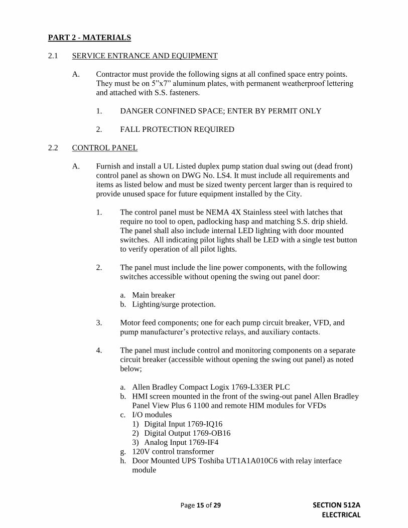
PART 2 - MATERIALS
2.1 SERVICE ENTRANCE AND EQUIPMENT
A. Contractor must provide the following signs at all confined space entry points.
They must be on 5”x7” aluminum plates, with permanent weatherproof lettering
and attached with S.S. fasteners.
1. DANGER CONFINED SPACE; ENTER BY PERMIT ONLY
2. FALL PROTECTION REQUIRED
2.2 CONTROL PANEL
A. Furnish and install a UL Listed duplex pump station dual swing out (dead front)
control panel as shown on DWG No. LS4. It must include all requirements and
items as listed below and must be sized twenty percent larger than is required to
provide unused space for future equipment installed by the City.
1. The control panel must be NEMA 4X Stainless steel with latches that
require no tool to open, padlocking hasp and matching S.S. drip shield.
The panel shall also include internal LED lighting with door mounted
switches. All indicating pilot lights shall be LED with a single test button
to verify operation of all pilot lights.
2. The panel must include the line power components, with the following
switches accessible without opening the swing out panel door:
a. Main breaker
b. Lighting/surge protection.
3. Motor feed components; one for each pump circuit breaker, VFD, and
pump manufacturer’s protective relays, and auxiliary contacts.
4. The panel must include control and monitoring components on a separate
circuit breaker (accessible without opening the swing out panel) as noted
below;
a. Allen Bradley Compact Logix 1769-L33ER PLC
b. HMI screen mounted in the front of the swing-out panel Allen Bradley
Panel View Plus 6 1100 and remote HIM modules for VFDs
c. I/O modules
1) Digital Input 1769-IQ16
2) Digital Output 1769-OB16
3) Analog Input 1769-IF4
g. 120V control transformer
h. Door Mounted UPS Toshiba UT1A1A010C6 with relay interface
module
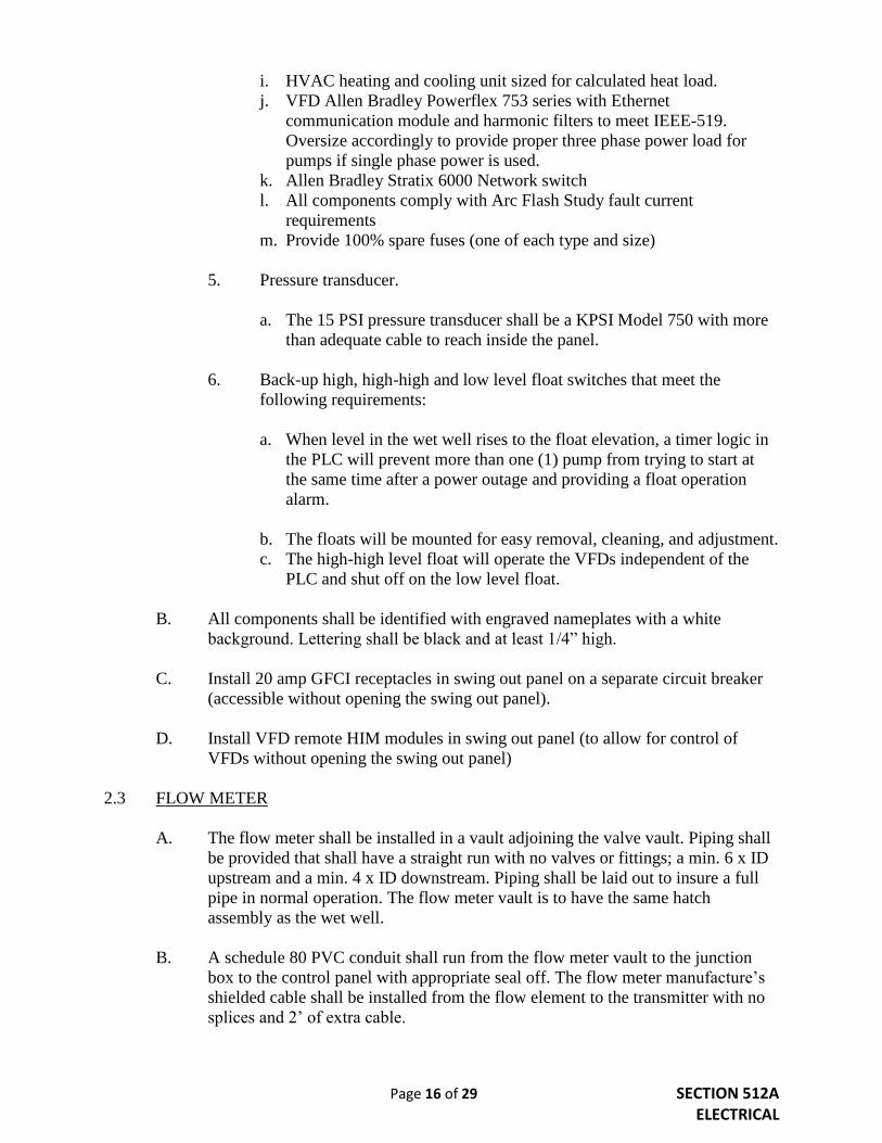
Page 16 of 29 SECTION 512A ELECTRICAL
i. HVAC heating and cooling unit sized for calculated heat load.
j. VFD Allen Bradley Powerflex 753 series with Ethernet
communication module and harmonic filters to meet IEEE-519.
Oversize accordingly to provide proper three phase power load for
pumps if single phase power is used.
k. Allen Bradley Stratix 6000 Network switch
l. All components comply with Arc Flash Study fault current
requirements
m. Provide 100% spare fuses (one of each type and size)
5. Pressure transducer.
a. The 15 PSI pressure transducer shall be a KPSI Model 750 with more
than adequate cable to reach inside the panel.
6. Back-up high, high-high and low level float switches that meet the
following requirements:
a. When level in the wet well rises to the float elevation, a timer logic in
the PLC will prevent more than one (1) pump from trying to start at
the same time after a power outage and providing a float operation
alarm.
b. The floats will be mounted for easy removal, cleaning, and adjustment.
c. The high-high level float will operate the VFDs independent of the
PLC and shut off on the low level float.
B. All components shall be identified with engraved nameplates with a white
background. Lettering shall be black and at least 1/4” high.
C. Install 20 amp GFCI receptacles in swing out panel on a separate circuit breaker
(accessible without opening the swing out panel).
D. Install VFD remote HIM modules in swing out panel (to allow for control of
VFDs without opening the swing out panel)
2.3 FLOW METER
A. The flow meter shall be installed in a vault adjoining the valve vault. Piping shall
be provided that shall have a straight run with no valves or fittings; a min. 6 x ID
upstream and a min. 4 x ID downstream. Piping shall be laid out to insure a full
pipe in normal operation. The flow meter vault is to have the same hatch
assembly as the wet well.
B. A schedule 80 PVC conduit shall run from the flow meter vault to the junction
box to the control panel with appropriate seal off. The flow meter manufacture’s
shielded cable shall be installed from the flow element to the transmitter with no
splices and 2’ of extra cable.

Page 17 of 29 SECTION 512A ELECTRICAL
2.4 CONDUIT
A. All exposed conduit to be PVC coated rigid.
B. All underground conduit to be schedule 80 PVC.
C. Minimum conduit size for motor feeders is two inches (2).
D. Provide two empty spare 2-inch conduits between wet well and electrical junction
box and from the junction box to the control panel.
2.5 CONDUCTORS
A. Conductors shall be copper unless otherwise specified.
B. The insulation for conductors, size #8 and smaller, shall be type THWN or
THHN.
C. Conductors shall be sized according to the drawings. All wire shall be stranded.
Minimum wire size shall be #12 except where specified for signal and pilot
control conductors.
D. Internal panel wiring shall be color-coded and any wiring leaving the panel shall
pass through properly numbered or coded terminal strips. Every switch, control
relay, circuit breaker, wiring and other component, either inside or outside the
control panel shall be visibly identified by permanently attached phenolic plates.
2.6 LOCATING TAPE
A. Material: Two inch red 4 mil polyethylene.
B. Labeling: “Caution – Buried Electrical Below” in 1½-inch minimum black
lettering.
PART 3 - WORKMANSHIP
3.1 SERVICE ENTRANCE AND EQUIPMENT
A. Signs
1. Signs as specified in section 2.1 must be posted at all confined space entry
points.
2. They must not pose a tripping hazard.

Page 18 of 29 SECTION 512A ELECTRICAL
B. Grounding
1. All electrical panelboards and equipment shall be grounded in accordance
with the requirements of the NEC. The neutral bus of panelboards shall be
grounded to the system ground and adjoining sections of switchgear
bonded together.
2. No portion of the electrical system shall be energized until the service
ground has been connected.
3.2 CONTROL PANEL
A. Safety features shall include the ability or devices to Lock Out/Tag out all
breakers, all resets and controls accessible without opening swing out panel.
3.3 CONDUIT
A. All systems of conduit must be installed completely before conductors are
pulled in.
B. Raceway ends shall be capped during construction. Conduits in which water or
foreign matter has accumulated shall be thoroughly cleaned to the satisfaction of
the Engineer or be replaced.
C. A tagged #12 AWG galvanized, or nylon, pull wire shall be provided in all empty
conduits with at least eighteen (18) inches coiled free at each end. Only tags with
a metal rim, made for this purpose, shall be used.
D. All conduit joints shall be cut square, threaded, reamed smooth and made up tight.
Bends or offsets shall be made with standard conduit ells. Field bends shall be
made with approved hickey, and conform to NEC limitations.
E. Provide two, two inch spare conduits from wet well to control panel and two, two
inch spare conduits from control panel to any below grade junction box. Spare
conduits must terminate below the panel and above the concrete base.
3.4 CONDUCTORS
A. All conductors shall be installed in conduit.
B. Conductors shall not be pulled into conduit until cabinets and outlet boxes are free
of foreign matter and moisture.
C. Conductors shall be continuous from outlet to outlet.
Page 19 of 29 SECTION 512A ELECTRICAL
3.5 SUPERVISORY CONTROL AND DATA ACQUISITION – SCADA
A. SCADA will be provided with a GE MDS-INET II RADIO through a 7 element
antenna mounted Telewave ANT930Y10-WR at an adequate elevation. SCADA
controls and alarms will be determined by the City of Meridian. SCADA
programming will be performed by a specialist selected by the City of Meridian.
SCADA communications shall be established and operational at both the remote
site and City of Meridian Wastewater Division prior to startup meeting.
B. Monitoring shall be provided by Ethernet for alarm and monitoring of each
pump’s amps through SCADA. Hour meters for each pump will be displayed on
the HMI and through SCADA. Monitoring for each pump, shall be provided on
the HMI hour meter, Run indication Seal Fail, Over-temp. High Level Alarm,
Low Level Alarm. High and low level alarms to be non-latching. Testing and
verification of all alarms shall be established prior to startup meeting.
END OF SECTION

Page 20 of 29 SECTION 512B SITE IMPROVEMENTS
SECTION 512B
SITE IMPROVEMENTS
PART 1 - GENERAL
1.1 SECTION INCLUDES
A. Site improvements to be installed as part of lift station construction.
PART 2 - MATERIALS
2.1 FENCING
A. The lift station site shall be enclosed with a six feet high chain link fence.
1. Minimum dimensions of the fence must be 16' x 24' but may be larger
depending on location, orientation and configuration of lift station site.
2. All fittings (i.e. sleeves, bands, clips, rail ends, tension bars and fasteners)
shall be steel.
3. All components and fabric shall be galvanized per ASTM A123, 2.0
oz./sq. ft. coating. Hardware shall be galvanized per ASTM A153, 2.0
oz./sq. ft. coating.
4. Gates
a. One double leaf 16' gate and one 3' single leaf gate shall be provided.
b. Gates shall be equipped with center gate stop and drop rod, three 180
degree hinges per leaf and hardware for padlock.
B. Component materials and dimensions are as follows:
1. Gate Posts Class 1, round 3.5 inch
2. Gate Frame Class 1, round 1.66 inch
3. Line Posts Class 1, round 1.9 inch
4. Corner/End Posts Class 1, round 2.875 inch
5. Top/Brace Rail Class 1, round 1.66 inch
6. Fabric 9 gage - 2 inch mesh
7. Tension Wire 6 gage - steel
8. Tie Wire Aluminum alloy steel wire
9. Caps Cast steel, galvanized, w/ set screw retainer

Page 21 of 29 SECTION 512B SITE IMPROVEMENTS
2.2 LIGHTING
A. One 3900 Lumen minimum, 50K LED flood light, shall be installed within the
fenced lift station area.
B. The pole light above the control panel and shall be operated by an output from the
PLC. The PLC will be programmed to automatically turn the light off after 30
min. The exact location will be determined during plan review and approval.
2.3 GRAVEL ACCESS ROAD AND INTERIOR AREA
A. Gravel for Lift Station access road and interior area shall be ¾” (Type 1) as
specified in Division 800, Section 802, Crushed Aggregates, of the ISPWC.
2.4 YARD HYDRANT
A. A 3/4 inch water service (see City of Meridian Supplemental Specifications
Standard Drawings W1 and W2), including a reduced pressure backflow
assembly shall be installed to the lift station lot with a minimum two foot by two
foot concrete pad.
PART 3 - WORKMANSHIP
3.1 FENCING
A. Install framework, fabric, accessories and gates in accordance with ASTM F567
and Division 2000, Section 2040, Fencing, of the ISPWC.
B. The entire fencing system is to be grounded in accordance with the most stringent
applicable code.
C. Gate Posts
1. Gate posts shall be installed in holes that are drilled in undisturbed earth
and shall be 16” in width by 3’ in depth and filled with concrete.
2. If gate posts are to be set in loose (or disturbed) material, a sonotube of the
listed dimensions shall be used to contain the concrete. Once the concrete
has cured, the material around the sonotube shall be compacted to 95% of
maximum dry density.
D. Line Posts
1. Line posts shall be set in concrete.
2. Spacing shall not exceed ten feet.

Page 22 of 29 SECTION 512B SITE IMPROVEMENTS
3.2 GRAVEL ACCESS ROAD AND GRAVELED INTERIOR AREA
A. Access Road
1. An all-weather gravel access road shall be constructed from the street to
the lift station with 10” of ¾” (Type 1) aggregate base, per the City of
Meridian Supplemental Specifications Standard Drawings; detail G2.
B. Lift Station Site
1. The entire area within the fenced lift station shall consist of 6" of ¾”
(Type 1) aggregate base. Shape, compact, and slope a minimum of 2%
away from the wet well, valve and flowmeter access.
3.3 YARD HYDRANT
A. A non-freeze, yard hydrant shall be installed at a location to be determined during
plan review and approval.
3.4 LANDSCAPING
A. Landscaping on the lift station lot shall not be installed without review approval
from the Public Works and Planning Departments.
END OF SECTION

Page 23 of 29 SECTION 512C
COMPLETION REQUIREMENTS
SECTION 512C
COMPLETION REQUIREMENTS
Prior to Lift Station approval and acceptance the Contractor shall complete the following:
1.1 FINAL CLEANING
A. Prior to final inspection, execute the following final cleaning items.
1. Clean site.
2. Sweep paved areas.
3. Rake and clean landscaped surfaces.
4. Remove waste, surplus materials and construction debris from the site.
1.2 ADJUSTMENTS
A. Adjust equipment to ensure smooth and unhindered operation.
1.3 OPERATION AND MAINTENANCE DATA
It is recommended that the Engineer submit one (1) copy of completed manual in final
form fifteen (15) days prior to the final inspection. This copy will be returned after the
final inspection, with Public Works Department comments. Revise content of documents
as required prior to final submittal.
A. Prior to final acceptance the following copies of the Operation and Maintenance
manuals are required.
1. Four (4) Hard Copies.
2. Two (2) complete copies on CD.
B. The manuals must be presented as follows:
1. Bound in D-size, three ring binders with durable plastic covers.
2. Binder covers must be titled "Operation and Maintenance Instructions"
and include the name of project.
3. Internally subdivide the binder contents with permanent page dividers,
logically organized as described in this section with tab titling clearly
printed under reinforced laminated plastic tabs.
4. Text pages must be on 8-1/2” x 11” sheets on thirty (30) pound bond white
paper.

Page 24 of 29 SECTION 512C
COMPLETION REQUIREMENTS
C. TABLE OF CONTENTS
1. Prepare a Table of Contents for each volume, with each product or system
description identified. Organization must be in the following general
layout:
PART 1: Directory listing names, addresses, and telephone numbers of
Design Engineer, Contractor, subcontractors, and major equipment
suppliers.
PART 2: Operation and maintenance instructions must be arranged by
process flow and subdivided by specification section. For each category,
identify names, address and telephone numbers of subcontractors and
suppliers. Identify the following:
a. Significant design criteria.
b. List of equipment.
c. Parts list for each component.
d. Operating instructions.
e. Maintenance instructions for equipment and systems.
f. Electrical to include: switchgear, paperback VFD manual,
manufacturer's recommended maintenance and operation instructions,
parts list with name, address and phone number of local source of
replacement parts.
PART 3: Project documents and certificates, including the following:
a. Shop drawings and product data.
b. Certificates.
c. Photocopies of warranties.
1.4 WARRANTIES
A. Warranties must be provided for the entire lift station for two (2) years from the
final date of acceptance.
1. Additional manufacturer’s warranties must be submitted for all
components.
B. Provide duplicate notarized copies.
C. Submit prior to request for final approval and acceptance.
D. For items of Work delayed beyond date of Substantial Completion, provide
updated submittal within ten (10) days after acceptance, listing date of acceptance
as start of warranty period.

Page 25 of 29 SECTION 512C
COMPLETION REQUIREMENTS
1.5 SPARE PARTS AND MAINTENANCE MATERIALS
A. Provide products, spare parts, maintenance and extra materials in quantities
specified in individual specification sections.
B. Deliver spare parts, extra materials and other required products to Wastewater
Division; obtain receipt prior to final approval and acceptance.
1.6 STATEMENT OF COMPLIANCE
The Design Engineer must submit a letter of compliance to the City of Meridian Public
Works Department prior to requesting a certificate of occupancy for any building.
END OF SECTION
Page 26 of 29 SECTION 512D SYSTEM START UP
SECTION 512D
SYSTEM START UP
1.1 GENERAL
The Contractor shall:
A. Coordinate a schedule for start-up of various equipment and systems. System
shall run for a minimum of 48 hours problem free prior to start up meeting.
B. Notify the Design Engineer, the Public Works Department, and Wastewater
Superintendent seven (7) days prior to start-up of each item.
C. Clean wet well of all construction debris prior to starting pumps.
D. Verify that each piece of equipment or system has been checked for proper
lubrication, drive rotation, belt tension, control sequence, or other conditions
which may cause damage.
E. Verify that tests, meter readings, and specified electrical characteristics agree with
those required by the equipment or system manufacturer.
F. Verify wiring and support components for equipment are complete and tested.
G. Execute start-up under supervision of responsible Manufacturer's representative,
City Representative, and Contractor’s personnel in accordance with
manufacturer's instructions.
H. Submit a written report that equipment or system has been properly installed and
is functioning correctly.
1.2 DEMONSTRATION AND INSTRUCTION
In addition to the requirements of Section 1.1 above, the Contractor shall:
A. Demonstrate operation and maintenance of the system to City personnel prior to
final acceptance. The Contractor shall provide the equipment manufacturer's
representative for a minimum of one (1) day of training to City personnel. The
Contractor shall coordinate and schedule demonstration of the system with the
Wastewater Division.
B. Utilize operation and maintenance manuals as basis for instruction. Review
contents of manual with City personnel in detail to explain all aspects of operation
and maintenance.
C. Demonstrate start-up, operation, control, adjustment, trouble-shooting, servicing,
maintenance, and shutdown of each item of equipment at agreed-upon times, at
equipment location.

Page 27 of 29 SECTION 512D
SYSTEM START UP
D. Prepare and insert additional data in operations and maintenance manuals when
need for additional data becomes apparent during instruction.
END OF SECTION

Page 28 of 29 SECTION 512E
OFF-PEAK PUMPING STATIONS
SECTION 512E
OFF-PEAK PUMPING STATIONS
1.1 GENERAL REQUIREMENTS
A. Design must follow all Lift Station Specifications as outlined in Sections 512A
through 512D. An exception may apply when these off-peak requirements cause a
conflict, use the off-peak applicable guideline.
B. Initial flows shall be via gravity sewer according to the current approved master
plan. When it is determined necessary, the flows shall be diverted to the lift
station and storage tank for off-peak pumping.
C. Minimum force main velocity of 2 ft/sec (per City specs) to be maintained at all
times.
D. Duplex pumping capability (minimum) with one (1) duty and one (1) lag pump.
E. Auto pumping and alarm at high level.
F. PLC based controls provided such that the on/off levels and/or times may be
adjusted according to downstream capacity needs.
G. Radio SCADA telemetry system GE MDS-INET II to tie in with City system.
H. Provide odor control and a method to eliminate the buildup of solids and grit
settling in the holding tank (aeration, mixing and filtered venting or approved
alternative).
I. Generator receptacle to accommodate City generators as well as generator(s) of
Contractor (permanent standby power is not required).
1.2 LENIENCIES
A. Use of ductile iron piping and appurtenances (in lieu of stainless steel) shall be
considered on a case by case basis.
B. Storage tanks may be installed in phases with development, as long as
150 gal/ERU storage is available at all times.
C. In the case of expected gravity sewer construction arriving to the service area,
smaller pumps may be used at first and sizing may be increased for future phases
of a subdivision (before final design pumping capacity is needed).

Page 29 of 29 SECTION 512E
OFF-PEAK PUMPING STATIONS
D. Demonstrate operation and maintenance of the system to City personnel prior to
final acceptance. The Contractor shall provide the equipment manufacturer's
representative for a minimum of one (1) day of training to City personnel. The
Contractor shall coordinate and schedule demonstration of the system with the
Wastewater Division.
END OF SECTION