SPECIFICATION - Taoglas - Antenna Solutions - 2G,...
40
SPE-12-8-125/A/WY Page 1 of 40 SPECIFICATION PATENT PENDING Part No. : TG.30.8113W Product Name : Apex White Hinged TG.30 Ultra-Wideband 4G LTE Antenna Feature : LTE / GSM / CDMA /DCS /PCS / WCDMA / UMTS / HSDPA / GPRS / EDGE /GPS /Wi-Fi 698MHz to 960MHz, 1575.42MHz 1710MHz to 2700Mhz Typical 70%+ Efficiency and 3dBi+ Peak Gain Dipole Swivel Terminal Antenna Hinged 90° termination with SMA(M) Connector RoHS Compliant
Transcript of SPECIFICATION - Taoglas - Antenna Solutions - 2G,...

SPE-12-8-125/A/WY Page 1 of 40
SPECIFICATION PATENT PENDING
Part No. : TG.30.8113W
Product Name : Apex White Hinged TG.30
Ultra-Wideband 4G LTE Antenna
Feature : LTE / GSM / CDMA /DCS /PCS / WCDMA / UMTS /
HSDPA / GPRS / EDGE /GPS /Wi-Fi
698MHz to 960MHz, 1575.42MHz
1710MHz to 2700Mhz
Typical 70%+ Efficiency and 3dBi+ Peak Gain
Dipole Swivel Terminal Antenna
Hinged 90° termination with SMA(M) Connector
RoHS Compliant
SPE-12-8-125/A/WY Page 2 of 40
1. Introduction
The hinged Apex TG.30 Ultra-Wideband Dipole LTE Antenna – is primarily designed for use
with 4G LTE modules and devices that require the highest possible efficiency and peak gain to
deliver best in class throughput on all major cellular (2g/3g/4g) bands worldwide for access
points, terminals and routers. The antenna is a ground plane independent antenna with a
SMA (M) connector and swivel mechanism that allows the antenna part to be rotated. The
Apex exhibits high efficiency across the ultra wide band and is backward compatible with 2G
and 3G cellular applications such as GSM, LTE, UMTS, WI-FI and even has GPS included for
Assisted GPS and/or E911 applications. With very high efficiency on every cellular band
globally it is an ideal solution for any device requiring high, reliable performance. It is also
guaranteed to meet any type approval or carrier certification requirements from a RF
standpoint. It is an omni-directional antenna and the radiation patterns display this and are
stable across all bands.
It has a quality robust IP67 UV resistant housing (SMA connector is IP65) for use with
wireless terminals. The swivel and hinge mechanism allows the antenna part itself to be
orientated in different directions and can help avoid touching off other antennas or objects
close by as well as helping with isolation by orientating the antenna in different directions in
MIMO systems for when other TG.30 antennas are present on the same device.
This patent pending antenna is available in White and Black versions. The antenna blade can
swivel 90 degrees from the connector accommodating different installation environments. It
is also available with Straight and Right Angle connectors.

SPE-12-8-125/A/WY Page 3 of 40
2. Specification
ELECTRICAL
Frequency (MHz) 700~800 824~960 1575.42 1710 ~ 1880 1850 ~ 1990 1710 ~ 2170 2400~2800
Peak Gain (dBi)
Free Space
Straight 1.1 0.3 1.1 1.9 2.7 2.6 2.7
Free Space Bent 2.6 1.5 2.9 2.7 3.1 3.1 2.0
30x30cm GP
center Straight 2.1 0.7 2.9 1.5 1.9 2.0 2.9
30x30cm GP
center Bent 3.5 1.7 5.2 5.9 6.7 6.4 4.9
30x30cm GP edge
Straight 2.6 1.3 1.7 2.1 2.1 2.3 4.3
30x30cm GP edge
Bent 2.6 1.8 3.1 2.1 3.0 2.8 5.1
PCB edge Straight 1.4 1.2 0.9 2.5 3.2 3.0 1.4
PCB edge Bent 2.1 0.1 2.1 2.4 3.6 3.4 3.0
Average Gain (dB)
Free Space
Straight -1.1 -2.2 -2.0 -1.5 -1.2 -1.3 -3.5
Free Space Bent -1.1 -2.3 -1.5 -1.5 -1.1 -1.2 -3.1
30x30cm GP
center Straight -0.6 -1.6 -2.0 -1.8 -1.7 -1.7 -3.8
30x30cm GP
center Bent -3.5 -4.9 -2.8 -2.4 -1.8 -2.0 -3.0
30x30cm GP edge
Straight -0.6 -1.5 -1.9 -1.6 -1.4 -1.4 -3.1
30x30cm GP edge
Bent -0.6 -1.7 -1.6 -1.5 -1.2 -1.3 -3.1
PCB edge Straight -1.0 -2.0 -2.0 -1.6 -1.4 -1.4 -3.5
PCB edge Bent -0.8 -2.5 -1.6 -1.5 -1.1 -1.3 -3.0

SPE-12-8-125/A/WY Page 4 of 40
ELECTRICAL
Frequency (MHz) 700~800 824~960 1575.42 1710 ~ 1880 1850 ~ 1990 1710 ~ 2170 2400~2800
Efficiency (%)
Free Space Straight 79 61 63 71 76 75 45
Free Space Bent 78 60 70 72 78 75 49
30x30cm GP center
Straight 86 69 62 66 67 68 42
30x30cm GP center
Bent 47 32 51 58 66 64 51
30x30cm GP edge
Straight 88 70 65 69 72 72 49
30x30cm GP edge
Bent 88 67 69 70 76 74 49
PCB edge Straight 80 63 63 69 73 73 45
PCB edge Bent 83 57 70 71 77 75 50
Impedance 50Ω
Polarization Linear
Radiation Pattern Omni
Input Power 10 W
MECHANICAL
Casing UV Resistant PC/ABS
Connector SMA Male Hinged 90°
ENVIRONMENTAL
Temperature Range -40°C to 85°C
Humidity Non-condensing 65°C 95% RH

SPE-12-8-125/A/WY Page 5 of 40
3. Antenna Characteristics
3.1 Return Loss

SPE-12-8-125/A/WY Page 6 of 40
3.2 Peak Gain

SPE-12-8-125/A/WY Page 7 of 40
3.3 Average Gain

SPE-12-8-125/A/WY Page 8 of 40
3.4 Efficiency

SPE-12-8-125/A/WY Page 9 of 40
4. Antenna Radiation Patterns
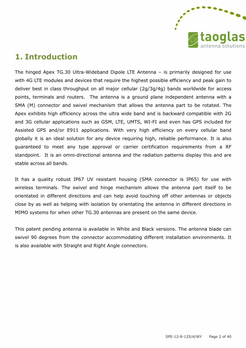
4.1 Antenna setup (Free Space Straight)
Radiation Patterns
XY plane
y
x
z

SPE-12-8-125/A/WY Page 10 of 40

SPE-12-8-125/A/WY Page 11 of 40
XZ plane

SPE-12-8-125/A/WY Page 12 of 40
4.2 Antenna setup (Free Space Bent)
y
x
z
SPE-12-8-125/A/WY Page 13 of 40
Radiation Patterns
XY plane

SPE-12-8-125/A/WY Page 14 of 40
XZ plane

SPE-12-8-125/A/WY Page 15 of 40

SPE-12-8-125/A/WY Page 16 of 40
4.3 Antenna setup (On 300x300mm ground center straight)

SPE-12-8-125/A/WY Page 17 of 40
Radiation Patterns
XY plane

SPE-12-8-125/A/WY Page 18 of 40
XZ plane

SPE-12-8-125/A/WY Page 19 of 40

SPE-12-8-125/A/WY Page 20 of 40
4.4 Antenna setup (On 300x300mm ground center bent)
Radiation Patterns
XY plane

SPE-12-8-125/A/WY Page 21 of 40

SPE-12-8-125/A/WY Page 22 of 40
XZ plane

SPE-12-8-125/A/WY Page 23 of 40
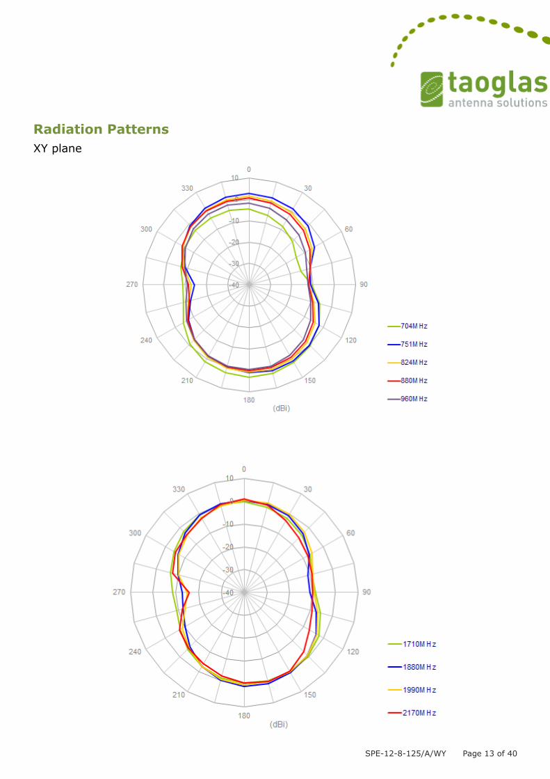
4.5 Antenna setup (On 300x300mm ground edge straight)

SPE-12-8-125/A/WY Page 24 of 40
Radiation Patterns
XY plane
SPE-12-8-125/A/WY Page 25 of 40

SPE-12-8-125/A/WY Page 26 of 40
XZ plane

SPE-12-8-125/A/WY Page 27 of 40
4.6 Antenna setup (On 300x300mm ground edge bent)

SPE-12-8-125/A/WY Page 28 of 40
Radiation Patterns
XY plane

SPE-12-8-125/A/WY Page 29 of 40

SPE-12-8-125/A/WY Page 30 of 40
XZ plane

SPE-12-8-125/A/WY Page 31 of 40
4.7 Antenna setup (On Ground edge straight)

SPE-12-8-125/A/WY Page 32 of 40
Radiation Patterns
XY plane

SPE-12-8-125/A/WY Page 33 of 40
XZ plane
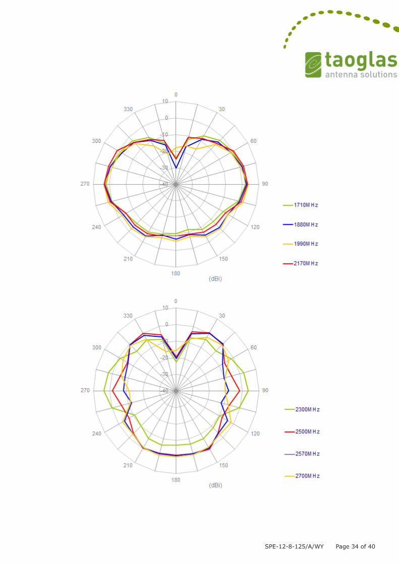
SPE-12-8-125/A/WY Page 34 of 40
SPE-12-8-125/A/WY Page 35 of 40
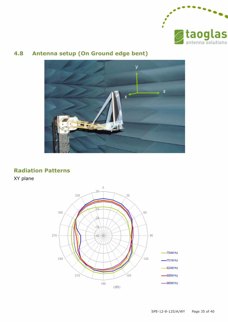
4.8 Antenna setup (On Ground edge bent)
Radiation Patterns
XY plane

SPE-12-8-125/A/WY Page 36 of 40

SPE-12-8-125/A/WY Page 37 of 40
XZ plane

SPE-12-8-125/A/WY Page 38 of 40

SPE-12-8-125/A/WY Page 39 of 40
5. Mechanical Drawing

SPE-12-8-125/A/WY Page 40 of 40
6. Packaging
Taoglas makes no warranties based on the accuracy or completeness of the contents of this document and reserves the right to make changes to specifications and product descriptions at any time without notice. Taoglas reserves all rights to this document and the information contained herein. Reproduction, use or disclosure to third parties without express permission is strictly prohibited. Copyright © 2012, Taoglas Ltd.