GENOM-POF: Multi-Objective Evolutionary Synthesis of Analog ICs with Corners Validation

Specification, Synthesis and Validation ofHardware/Software Interfaces
Mattias O’Nils
Stockholm 1999
Electronic system Design, Department of ElectronicsElectrum 229, Isafjordsgatan 22-26
S-164 40 Kista, Sweden
Submitted to the School of Electrical Engineering, Royal Institute oftechnology, in partial fulfillment of the requirements for the degree
of Technical Doctor.


Abstract
Design based on intellectual property (IP) is emerging to close the gap between steadilyincreasing capacity, in terms of transistors on integrated devices, and design productivity,in terms of the number of transistors designed in a given period. However, the integrationof several IP blocks into a single system on one chip makes the specification and imple-mentation of interfaces (for example, bus interfaces and device drivers) a dominant designproblem for embedded systems. There is therefore a need for effective ways of modelling,refining, and implementing communication within embedded systems.
This thesis presents one approach to hardware/software interface synthesis that rangesfrom the specification to the implementation and validation of hardware/software inter-face protocols. The information required for hardware/software interface synthesis is sep-arated into three parts: the protocol specification, information related to the operatingsystem, and information related to the processor. From these inputs a synthesis tool gener-ates (a) device driver functions, (b) a combination of device driver functions and a DMAcontroller, or (c) simulation models, depending on what the designer decides. The cleanseparation of information facilitates (1) efficient design space exploration with combina-tions of different processors, operating systems and protocols, and (2) efficient mainte-nance of a large number of different versions and variants of hardware/softwareinterfaces. The three-phase validation approach is based on standard simulation methodsand facilitates simulation of the interfaces at several steps during development. We keepall the simulation models consistent with both the specification and the implementationby generating the models using the same technique that is used for synthesis. Validationin several phases is justified (1) by the faster simulation of early phases (up to four timesfaster than late phases), and (2) by allowing both hardware designers and software devel-opers to work in their familiar tool environments as long as possible.
Protocols are specified as a grammar, which is fully independent of architecture andimplementation. After the initial selection of implementation alternatives, the methodspresented are fully automated. Using real-life examples we demonstrate the effectivenessof the simulation models and show that the quality of the generated code is close to hand-written quality in terms of performance, area and code size.


Acknowledgements
I would like to begin by expressing my gratitude to Professor Hannu Tenhunen for accept-ing me as a PhD student at the Electronic System Design Laboratory. I would also like tosend huge thanks to Dr Axel Jantsch for agreeing to be my supervisor and for his littlejokes, which helped me overcome the setbacks caused by rejected papers and other obsta-cles. In my opinion Axel’s supervision has been a textbook example of how a supervisorshould work.
I am very grateful to Professor Ahmed A. Jerraya for agreeing to be the opponent of thisthesis.
I would also like to thank the people at the ESD Lab at the Royal Institute of Technology,especially Henrik Olson for making my stays in Kista more fun, and Johnny Öberg for hishelp during this work, together with the people at ITE, Mid Sweden University, for beinggood colleagues, specially Hans-Erik Nilsson and Bengt Oelmann for all the useful andfun discussions. Thanks also to Miguel Berg and the system administrators in both Stock-holm and Sundsvall for helping me with computer problem and, of course, a big thankyou to my golfing partners Claes Lindkvist, Stefan Pettersson and Per-Erik Näsholm, whotogether with the floorball team Sundsvall Academics helped take my mind off work.
Ingalill Arnfridsson, you’re a well of patience and smiles. Thanks for all the help witharranging my travels and other boring administrative stuff during my time as a PhD stu-dent.
I would like to thank the following for their financial support: Mid Sweden University, theSwedish National Board for Industrial and Technical Development – NUTEK, and theSwedish Foundation for Strategic Research – SSF.
Lastly I would like to take the opportunity to thank my loving girlfriend Susanne for allher support and love. Without you, life would be so boring.
Sundsvall, May 1999
Mattias O’Nils


Contents
Abstract i
Acknowledgements iii
Contents v
Abbreviations and Acronyms vii
List of Figures xi
List of Papers xiii
1 Introduction 11.1 Thesis outline .............................................................................................. 3
2 Embedded systems 52.1 Design challenges........................................................................................ 7
2.1.1 Specification..............................................................................................72.1.2 Design .......................................................................................................92.1.3 Validation ................................................................................................10
2.2 History of codesign research ..................................................................... 102.2.1 Vulcan .....................................................................................................112.2.2 COSYMA................................................................................................12
2.3 Advanced research..................................................................................... 132.3.1 COSMOS ................................................................................................132.3.2 Polis.........................................................................................................142.3.3 CoWare....................................................................................................152.3.4 Chinook...................................................................................................152.3.5 SpecSyn...................................................................................................162.3.6 Tosca .......................................................................................................162.3.7 Miscellaneous approaches.......................................................................172.3.8 Summary .................................................................................................18
3 HW/SW interface design 213.1 Definition................................................................................................... 213.2 Motivation ................................................................................................. 233.3 HW/SW Interface synthesis ...................................................................... 24
3.3.1 Device driver synthesis ...........................................................................253.3.2 Bus interfaces synthesis ..........................................................................27
3.4 Validation................................................................................................... 273.5 ComSyn..................................................................................................... 30
3.5.3 Objective .................................................................................................30

vi Contents
3.5.4 Design flow .............................................................................................323.5.5 Target architecture...................................................................................333.5.6 Protocol modelling in ProGram..............................................................34
4 Summary of papers 374.1 Analysis and problem formulation ............................................................37
4.1.1 Paper 1, Norchip 1997 ............................................................................374.1.2 Paper 8, Norchip 1998 ............................................................................38
4.2 Protocol description ...................................................................................384.2.3 Paper 2, Euromicro 1998 ........................................................................38
4.3 Protocol synthesis ......................................................................................384.3.4 Paper 3, DATE 1999 ...............................................................................384.3.5 Paper 4, VLSI Design 1999 ....................................................................394.3.6 Paper 5, Kluwer DAES Submitted 1999.................................................39
4.4 Protocol validation.....................................................................................394.4.7 Paper 6, HLDVT 1998 ............................................................................394.4.8 Paper 7, IPSDP 1998...............................................................................41
4.5 Author’s contributions ...............................................................................41
5 Thesis summary 435.1 Conclusions................................................................................................435.2 Future work................................................................................................44
5.2.1 Specification............................................................................................445.2.2 Synthesis .................................................................................................445.2.3 Target architecture...................................................................................45
6 References 47
Paper 1 57
Paper 2 67
Paper 3 73
Paper 4 81
Paper 5 91
Paper 6 123
Paper 7 133
Paper 8 141

Abbreviations and Acronyms
GeneralADC. . . . . . . . . . . . . . Analog to Digital Converter
AMPS . . . . . . . . . . . . Advanced Mobile Phone System
API. . . . . . . . . . . . . . . Application Program Interface
ARM . . . . . . . . . . . . . Advanced RISC Machines
ASIC . . . . . . . . . . . . . Application Specific Integrated Circuit
ATM. . . . . . . . . . . . . . Asynchronous Transfer Mode
CAD. . . . . . . . . . . . . . Computer Aided Design
CAN. . . . . . . . . . . . . . Controller Area Network
CISC . . . . . . . . . . . . . Complex Instruction Set Computer
CMOS . . . . . . . . . . . . Complementary MOS
CORBA . . . . . . . . . . . Common Object Request Broker Architecture
CSP . . . . . . . . . . . . . . Communicating Sequential Processes
D-AMPS . . . . . . . . . . Digital AMPS
DAC. . . . . . . . . . . . . . Digital to Analog Converter
DMA . . . . . . . . . . . . . Direct Memory Access
DMAC . . . . . . . . . . . . DMA Controller
DRAM . . . . . . . . . . . . Dynamic RAM
DSP . . . . . . . . . . . . . . Digital Signal Processing
EDA. . . . . . . . . . . . . . Electronic Design Automation
FIFO . . . . . . . . . . . . . First In First Out
FSM. . . . . . . . . . . . . . Finite State Machine
GSM . . . . . . . . . . . . . Global System for Mobile Communications
HCCS. . . . . . . . . . . . . Host Code Cosimulation
HDL. . . . . . . . . . . . . . Hardware Description Language
HLS . . . . . . . . . . . . . . High Level Synthesis
HW . . . . . . . . . . . . . . Hardware
I/O . . . . . . . . . . . . . . . Input/Output

viii Abbreviations and Acronyms
I2C . . . . . . . . . . . . . . .Inter Integrated Circuit bus
IEE . . . . . . . . . . . . . . .Institution of Electric Engineers
IEEE . . . . . . . . . . . . . .Institute of Electrical and Electronic Engineers
IP . . . . . . . . . . . . . . . .Intellectual Property
ISR . . . . . . . . . . . . . . .Interrupt Service Routine
ISS . . . . . . . . . . . . . . .Instruction Set Simulator
LoC. . . . . . . . . . . . . . .Lines of Code
MOS . . . . . . . . . . . . . .Metal-Oxide-Silicon
NUTEK . . . . . . . . . . .Swedish National Board for Industrial and Technical Development
OAM. . . . . . . . . . . . . .Operation and Maintenance
OS. . . . . . . . . . . . . . . .Operating System
ProGram . . . . . . . . . . .Protocol Grammar
RAM. . . . . . . . . . . . . .Random Access Memory
RISC. . . . . . . . . . . . . .Reduced Instruction Set Computer
ROM. . . . . . . . . . . . . .Read Only Memory
RPC . . . . . . . . . . . . . .Remote Procedure Call
RTL. . . . . . . . . . . . . . .Register Transfer Level
RTOS . . . . . . . . . . . . .Real-Time Operating System
PC. . . . . . . . . . . . . . . .Personal Computer
PDA . . . . . . . . . . . . . .Personal Digital Assistant
SDL . . . . . . . . . . . . . .Specification and Description Language
SSF . . . . . . . . . . . . . . .Swedish Foundation for Strategic Research
SW . . . . . . . . . . . . . . .Software
TCCS . . . . . . . . . . . . .Target Code Cosimulation
TDMA . . . . . . . . . . . .Time Division Multiple Access
UART . . . . . . . . . . . . .Universal Asynchronous Receiver Transmitter
USART. . . . . . . . . . . .Universal Synchronous/Asynchronous Receiver Transmitter
VHDL. . . . . . . . . . . . .VHSIC Hardware Description Language
VHSIC . . . . . . . . . . . .Very High Speed Integrated Circuit
VLSI . . . . . . . . . . . . . .Very Large Scale Integration
VSI . . . . . . . . . . . . . . .Virtual Socket Initiative
YACC . . . . . . . . . . . . .Yet Another Compiler Compiler

ix
Research groups and approachesAKKA . . . . . . . . . . . . Royal Institute of Technology’s early codesign approach
CASTLE . . . . . . . . . . Codesign and Architecture driven Synthesis TooL Environment
CCG. . . . . . . . . . . . . . Communication Classification Graph, defined in [89]
CFSM . . . . . . . . . . . . Codesign FSM, defined in [28]
Chinook . . . . . . . . . . . University of Washington’s codesign approach
CodeSign . . . . . . . . . . Object oriented codesign approach, ETH, Zurich, Swiss
ComSyn . . . . . . . . . . . Royal Inst. of Techonlogy’s HW/SW interface synthesis tool
COSMOS. . . . . . . . . . An SDL-based Codesign Tool, TIMA, Grenoble, France
COSYMA . . . . . . . . . COSYnthesis for eMbedded Architectures
Cx. . . . . . . . . . . . . . . . Super set of C, defined in [50]
ESG . . . . . . . . . . . . . . Extended Syntax Graph, defined in [19]
FGM . . . . . . . . . . . . . Flow Graph Model, defined in [83]
HardwareC. . . . . . . . . Modified C dialect for hardware synthesis
LYCOS . . . . . . . . . . . LYngby COSynthesis system
Polis . . . . . . . . . . . . . . A codesign system for control application, Berkley, USA
PSM. . . . . . . . . . . . . . Program State Machine, defined in [55]
RTC . . . . . . . . . . . . . . Register Transfer C, defined in[21]
SOLAR . . . . . . . . . . . FSM based design representation, used in COSMOS
SpecSyn . . . . . . . . . . . University of California - Irvine’s codesign approach
STG . . . . . . . . . . . . . . Signal Transition Graph, defined in [80]
Tosca . . . . . . . . . . . . . Politecnico di Milano’s codesign approach
Vulcan . . . . . . . . . . . . Early codesign approach presented in [58]

x Abbreviations and Acronyms

List of FiguresFigure 1.1: The growing gap between what engineering teams can design
and what fabrication lines can economically produce [53]. ...............2Figure 1.2: Organization of the thesis. ..................................................................4Figure 2.1: Products that include embedded systems. ..........................................5Figure 2.2: Typical embedded system...................................................................7Figure 2.3: System synthesis design flow..............................................................8Figure 2.4: Vulcan design flow............................................................................11Figure 2.5: COSYMA design flow. .....................................................................13Figure 3.1: Communication routes in a heterogeneous embedded system. ........21Figure 3.2: Break down of the HW/SW communication into different parts. ....22Figure 3.3: Simplified schematic of the pay phone controller system. ...............23Figure 3.4: Mapping of hardware/software communication protocols onto
selected architecture. ........................................................................24Figure 3.5: HW/SW interface design flows. (a) Without HW/SW interface
synthesis tool and (b) with a HW/SW interfacesynthesis tool. ...................................................................................25
Figure 3.6: Device driver protocol mapped onto an architecture........................30Figure 3.7: Providing device driver implementation for two device driver
protocols mapped onto two RT-kernels and two processors,using two different APIs, with and without DMA. (a) describesthe generation of implementation with the ComSyn approach,and (b) with a handwritten library. ...................................................32
Figure 3.8: Overview of the ComSyn synthesis system......................................33Figure 3.9: Simulation levels in embedded hardware/software systems
development: (a) system description simulation, (b) HW/SWstub simulation, (c) HW/SW host code cosimulation, and(d) target code cosimulation. ............................................................34
Figure 3.10: Grammar rule with actions. ..............................................................35Figure 4.1: Identification of paper contents in the ComSyn design flow. ...........37

xii List of Figures

List of Papers
Papers included in this thesis:
1. Mattias O’Nils, Axel Jantsch, “Communication in Hardware/Software Embedded Sys-tems - A Taxonomy and Problem Formulation”,Proceedings of the 15th IEEE NorchipConference, pp. 67-74, 1997.
2. Mattias O’Nils, Johnny Öberg, Axel Jantsch, “Grammar Based Modelling and Synthe-sis of Device Drivers and Bus Interfaces”,Proceedings of EUROMICRO Conference,pp. 55-58, 1998.
3. Mattias O’Nils, Axel Jantsch, “Operating System Sensitive Device Driver Synthesisfrom Implementation Independent Protocol Specification”,Proceedings of Design,Automation and Test in Europe (DATE), pp. 562-567, 1999.
4. Mattias O’Nils, Axel Jantsch, “Generation of DMA Controllers from Device DriverDescriptions”,Proceedings of IEEE VLSI Design Conference, pp. 138-145, 1999.
5. Mattias O’Nils, Axel Jantsch, “Device Driver and DMA Controller Synthesis fromHW/SW Communication Protocol Specifications”, submitted toDesign Automationfor Embedded Systems, Kluwer Academics Publisher, 1999.
6. Mattias O’Nils and Axel Jantsch, “Multi-phase Validation of Hardware/Software Inter-faces based on Generated Simulation Models”,Proceedings of the IEEE InternationalHigh Level Design Validation and Test Workshop, pp. 40-46, 1998.
7. Mattias O’Nils, Axel Jantsch, “HW/SW Interface Validation in IP based SystemDesign”,Proceedings of International. Workshop on IP based Synthesis and SystemDesign, pp. 79-84, 1998.
8. Mattias O’Nils, Axel Jantsch, “Refinement of HW/SW Communication Channels:Case Study and Comparison”,Proceedings of the 16th IEEE Norchip Conference, pp.230-237, 1998.
xiv List of Papers
Other papers:
1. Mattias O'Nils, Kalle Tammemäe, Axel Jantsch, Ahmed Hemani, Hannu Tenhunen,“Experiences using Akka: A Hardware-Software Codesign Tool Kit in design of Tele-communication systems”, Poster session of CAVE'95 Workshop, 1995.
2. Kalle Tammemäe, Mattias O'Nils, Axel Jantsch, Ahmed Hemani, “AKKA: A CodesignEnvironment”,Proceedings of 13th Norchip Conference, pp. 249, 1995.
3. Mattias O'Nils, Axel Jantsch, Ahmed Hemani, Hannu Tenhunen, “Interactive Hard-ware-Software Partitioning and Memory Allocation Based on Data Transfer Profiling”,Proceeding of International Conference on Recent Advances in Mechatronics, pp. 447-452, 1995.
4. Kalle Tammemäe, Mattias O'Nils, Anders Tornemo, Hannu Tenhunen, “VLSI SystemLevel Codesign Toolkit AKKA”,Proceedings of the 14th IEEE Norchip Conference,pp. 196-202, 1996.
5. Mattias O'Nils, Kalle Tammemäe, Axel Jantsch, Ahmed Hemani, “Design of D-AMPSChannel Decoder with Codesign Methodologies”,Proceedings of Baltic ElectronicConference, pp.397-400, 1996.
6. Kalle Tammemäe, Mattias O'Nils, Ahmed Hemani, “Flexible Codesign Target Archi-tecture for Early Prototyping of CMIST Systems”,Field-Programmable Logic SmartApplication, New Paradigms and Compilers, Springer-Verlag, ISBN 3-540-61730- 2,pp.193-199, 1996.
7. Kalle Tammemäe, Mattias O'Nils, Axel Jantsch and Ahmed Hemani, “AKKA: A Tool-kit for Cosynthesis and Prototyping”,IEE Digest no:96/036 of Colloquim on Hard-ware-Software Cosynthesis for Reconfigurable Systems, pp.8/1-8/8, 1996.
8. Bengt Oelmann, Mattias O’Nils, “Asynchronous Control of Low-Power Gated-ClockFinite-State Machines”,Proceedings of IEEE International Conference on Electronics,Circuits and Systems, 1999.
9. Bengt Oelmann, Mattias O'Nils, “A Low Power Hand-Over Mechanism for Gated-Clock FSMs”,Proceedings of the European Conference on Circuit Theory and Design,1999.

1 Introduction
Many types of electronic systems exist and they can be found almost everywhere, forexample, cellular telephones, toys, cars, and so on. Looking at the evolution of electronicproducts one can identify several characteristics that are becoming more important, andwill therefore also influence the design process. The characteristics are increased systemfunctionality, more-portable systems (that is, battery operated), and shorterproduct life-
time. Table 1.1 outlines how the different characteristics will influence the design process.The first and second columns indicate the product trend. Columns 3 and 4 show how eachtrend affects the design and the design process.
Both the increase in system complexity and the requirements for low-power operationlead to increased design time. Increased complexity can also lead to increased power con-sumption. Design time will therefore increase because the designer needs to put moreeffort into low-power design. At the same time, the decreasedproduct lifetimerequires areduction in design time. The design task will thus become more complex and the designtime for these systems will need to be reduced. In short, the electronic systems designprocess has to be made more efficient by using better design methods.
In the past the driving force behind increased electronic system complexity has been theadvances in silicon technology. Figure 1.1 shows that the gap is increasing between sili-con capacity, in terms of the number of gates on a chip, and the size of designs. Thus thelimitations are moving towards design productivity rather then technology capacity. Thisis becoming a problem for silicon vendors because their production capacity is not fullyused, leading them to take more interest in design issues in recent years [6,15].
Table 1.1: Electronic product trends and their effects on product design.
Product trend ∆ This leads to ∆Increasing complexity Increasing design time
Increasing power
Decreasing power Increasing design time
Decreasing product lifetime Decreasing design time

2 Introduction
In conclusion we see that there is a demand for more-efficient design methods from bothconsumers and producers of electronic systems. This demand also includes efficientdesign methods for low power. There are several ways of increasing electronic designproductivity. This thesis concentrates on the system design of the digital parts of embed-ded systems. However, there exist several unsolved problems in other areas such as ana-log design [78], electronic system packaging [9] and the integration/testing of electronicsystems [3,68].
There are two major ways of achieving increased design productivity: (1) using computeraided design (CAD) tools, and (2) using design based on intellectual property (IP) com-ponents. There are several techniques to achieve low-power operation for a system. Thisis also reflected in several research approaches for low-power implementations, for exam-ple: asynchronous logic [96], highly parallel low-speed structures [22,26], isosynchro-nous techniques [5,61] or power management techniques [17].
The predominant computer aid for hardware design is still schematic capture and logicsynthesis [39]. Design tools for higher levels of abstractions are becoming more matureand have resulted in tools for graphical design [103] and tools for high-level synthesis(HLS) [24,54].
The reuse of hardware IP components is starting to gain recognition in the designer com-munity. The VSI Alliance [117] for the documentation and exchange of hardware IP com-
1994 1995 1996 1997 1998 19990.6µ 0.5µ 0.35µ 0.25µ 0.2µ 0.15µ
Log
scal
e [G
ates
/cm
2 ]
Average Cell-basedDesign Start
Figure 1.1: The growing gap between what engineering teams can design and what fabricationlines can economically produce [53].
Moore’s Law
100k125k
156k195k
244k305k
380k
603k
957k
1,520k
2,410k
3,830k
Widening Gap

1.1 Thesis outline 3
ponents is a good start, but there are still many issues that have to be solved to enable thecomplete success of IP-based hardware design, for example, copyright protection [27],the validation of IP components [38,93] and CAD tools for IP-based design (communica-tion synthesis) [100,115,124].
Tools accepted and widely used by the software-designer community are C cross compil-ers and debuggers for particular microprocessors. These tools are usually not portable,that is, a software development system will only support one processor family (processorarchitecture). Only a few software CAD tools support different optimization strategiesand analysis methods for size/performance/power constraints. Tools exists for higher lev-els of abstractions for software synthesis, that is, case tools [34,42]. These tools enabledesigners to work on a higher level of abstraction while the tools themselves handle thelow-level implementation details. These tools have not yet gained widespread recogni-tion. The reuse of software IP components (code) has been proposed and debated for along time in the software community. It is only recently, with approaches like Corba [35]and JavaBeans [73], that IP-based software design has gained acceptance among design-ers.
Hardware/software codesign1 is the next evolutionary step for embedded systems CADtools. Hardware/software codesign research has been going on for about 10 years[46,55,82,118]. Although the joint design of hardware and software is much older thanthis, the concept of hardware/software codesign is to merge the design flows for hardwareand software into one hardware/software design flow. In recent years codesign researchhas resulted in a few commercial design tools like Coware [21], Arexsys [105] and Felix[104]. Most approaches to hardware/software codesign focus on top-down design, that is,starting from a high-level specification that is then refined into an implementation. Only afew research groups focus on methods for IP-based design [47,92,122].
1.1 Thesis outline
The next section goes through embedded systems, embedded systems’ design and theresearch in hardware/software codesign. Section 3 analyses the task of hardware/softwareinterfacing and describes the related work in this area. It also describes the ComSyn sys-tem, that is, the hardware/software communication synthesis system presented in theappended papers. Section 4 summarizes the work covered by all papers included in this
1. “HW/SW codesign means meeting system-level objectives by exploiting the synergism of hardwareand software through their concurrent design.” – Giovanni De Micheli, Stanford University.

4 Introduction
thesis. Section 5 summarizes and concludes the contributions of this thesis. It also indi-cates unresolved problems in communication synthesis. The eight papers that present theoriginal contribution are appended to the end of the thesis.
HW/SW
analysisCommunication
Paper 1Paper 8
HW/SWProtocol
Specification
Paper 2
HW/SWProtocol
Implementation
Paper 3Paper 4Paper 5
HW/SWProtocol
Verification
Paper 6Paper 7
Papers included in thesis
Figure 1.2: Organization of the thesis.
2.1 Design challenges 2.2 History of codesign research
2.3 Advanced research
3.1 Definition 3.2 Motivation
3.3 HW/SW Interface synthesis 3.4 Validation
3.5 ComSyn
1 Introduction
2 Embedded systems
3 HW/SW interface design
4 Summary of papers 5 Thesis summary 6 References

2 Embedded systems
Today embedded computer systems have become everyday gadgets for most people, whouse them even without even knowing it. Figure 2.1 and the bulleted items below showsome examples of things, taken from the author’s daily life, that contain one or moreembedded computer systems. Each example includes a description of tasks that can becarried out by embedded systems.
• microwave oven – providing the user interface and controlling the cooking of food.
• audio equipment – providing the user interface and processing the audio data.
• engine preheater – providing the user interface and controlling the power to the pre-heater in accordance with the user’s wishes and the climatic conditions.
• cars– today cars usually contain several embedded systems: anti-lock brake controller,ignition control, air conditioning controller, etc.
• cellular phone – providing the user interface, encoding data, speech compression, etc.
• TV set-top box – controlling the on-screen user interface, image processing, etc.
• Answering machine – compressing and storing speech data.
One reason why embedded computer systems are so popular is the combination of high-performance hardware with flexible software that has a short design time. The firstembedded systems were banking and transaction systems running on mainframes and
Figure 2.1: Products that include embedded systems.

6 Embedded systems
arrays of disks. Since this sort of equipment was built from very expensive components, itwas used for relatively few but important applications. When equipment was as expensiveas the early mainframes were, it was easy to motivate high costs for the design and main-tenance of systems.
What is an embedded system?There are probably as many definitions of what an embed-ded system is as there are designers. The word embedded implies that the system will notchange after it has been designed, and that it has a specific task. This makes sense for theexamples above, but there is actually no generally accepted definition of what an embed-ded system is. For example, is a PC that only runs a phone book application an embeddedsystem? Or is a PDA that uses the same processor running the same phone book applica-tion an embedded system? All embedded systems mentioned in this thesis refer to hard-ware/software systems with one or more microprocessors, similar to the system shown infigure 2.2.
An embedded system has several components (see figure 2.2), but the most importantdevice, which has enabled the evolution of embedded systems, is the microprocessor [64].The microprocessor has evolved from the simple 4004 [33] from Intel with only a fewthousand transistors, to the microprocessors of today (1999) with 6.5 to 100 million tran-sistors on a single chip, for example, the AlphaTM 21364 [13], the PowerPCTM 750 [102],the Pentium IITM[101]. The invention of the microprocessor enabled the use of embeddedsystems in low-cost consumer products like the ones listed above. The complexities of theprocessors mentioned above, together with memory devices containing up to 256 milliondevices on a single chip [1], have made it possible for chips to contain entire systems.This in turn enables system functionality well beyond traditional ASIC-based systems,for example, a whole GSM mobile phone can now be integrated on a single chip.
The complexities of today’s systems mean that many problems will emerge during thedesign process, as mentioned in the introduction. First of all, the design of embedded sys-tems embraces several design areas such as distributed system design for linking the sys-tem’s network of communicating microprocessors and real-time design to ensure that theembedded system operates within the time constraints set by the user. These constraintsmay be soft, as with a laser printer, where a delay in printing a page is not critical, or theymay be hard, as with an autopilot, which must without fail respond in real time. Manyembedded systems include at least a few hard real-time constraints. The designer’s job isto choose the engine that does the job most economically, but at the same time satisfysuch constraints as physical size and power consumption. However, it is performance

2.1 Design challenges 7
constraints, particularly the hard real-time deadlines, that determine the basic require-ments of a hardware engine.
2.1 Design challenges
To refine an embedded system from idea to finished product, a designer has to perform ahuge number of design and validation tasks. A great deal of effort is being put into devel-oping a design tool that offers computer aided design support for the whole design proc-ess, but several design sub-problems have yet to be analysed and researched before a toolfor system synthesis becomes reality. Figure 2.3 shows a design flow for the design ofhardware/software embedded systems. The tasks within this design flow are identifiedbelow. The different design tasks are divided into three different classes: specification,design and validation.
2.1.1 Specification
Many different aspects of a system have to be captured in a specification, that is, behav-iour, architecture and requirements. Writing a specification is a very challenging tasksince the specification should be unambiguous, consistent and complete. Specificationshave traditionally been captured, if at all, in natural language. The challenge for the futurein the area of specification is to find formal methods of capturing the information neededto specify an embedded system.
Figure 2.2: Typical embedded system.
Embedded System
ProcessorCore(s)
RAM
ROM
DMA
Application Specific
AD Converter
DA Converter
I/O Interface(s)Logic

8 Embedded systems
• Behavioural specification. Captures the functional parts of a system, such as algo-rithms and control flow.
• Architectural specification. Describes the architectural parts of the system, that is,describes all parts of the system that are reused (for example, processors and IP Com-ponents).
• Requirements specification. Describes non-functional system requirements, for exam-ple, throughput constraints, power consumption constraints and descriptions of exter-nal interfaces.
• Executable specification. Captures the behaviour of the system in a format that can beexecuted on a computer, thus enabling validation and elaboration of system properties.
Figure 2.3: System synthesis design flow.
Specification- Requirements- Behaviour
Executable spec.
control-flowSpec. of Spec. of
data-flow
Design
Val
idat
ion
Data-flow oriented Control-flow oriented
Task assignmentFix. arithmetic precision
Scheduling of tasksHW/SW partitioning
Estimation
- Architecture
Communication synthesisInterface synthesis
Code generationGeneration of glue logic
Partitioned spec.
The
orem
pro
ofing
Mod
el c
heck
ing
Sim
ulat
ion
Test
Integration
Pro
toty
ping

2.1 Design challenges 9
• Specification partitioning. Partitions a specification into, for example, control- anddata-flow dominated parts, that is, individual specifications of parts of the system thatneed to be handled in different design flows.
2.1.2 Design
To transform a specification into an implementation, a designer has to go through severalrefinement steps. The design task can be divided into four stages: (1) applying the specifi-cation to a specific implementation and estimating design properties, (2) assigning thespecification to execution units and scheduling it, (3) synthesizing the interconnections,and (4) code generation and integration.
• Task assignment. Break down the specification into a set of tasks that perform the sys-tem functionality to enable concurrency and optimization.
• Fix arithmetic precision. For fixed-point implementation, the arithmetic width has tobe defined and verified so that the implementation meets the initial specification.
• Estimation. Estimate cost parameters for both hardware and software. Cost parameterscan be, for example, timing performance, gate count (HW), code size (SW), power,memory size, and statistics on execution frequency. Estimated values are used to aiddesigners/tools to make design decisions, thus decreasing the number of design itera-tions.
• Allocation. Allocate a set of processors and execution units that will deliver enoughcomputation power to meet all cost, performance and other constraints.
• Hardware/software partitioning. Partition a system into multiple processors and otherexecution units. Partitioning decisions should consider timing, power and other costconstraints.
• Scheduling. Find a system schedule and allocation, taking into consideration timingconstraints and the need to minimize system costs.
• Communication synthesis. Define the communication protocol from the system specifi-cation, select a suitable communication architecture that fulfils a set of communicationconstraints, and map the communication protocol onto the selected architecture.
• Code generation. Generate code that is optimized for each specific execution unit.
• Integration. Integrate hardware, software, memory, etc. into a complete system.
Most of the design tasks will affect each other’s results. For example, the allocation willaffect the partitioning, scheduling and communication synthesis, but at the same time thecommunication synthesis can affect all the others. The quality of all design decisionsdepends on the quality of the estimation values.

10 Embedded systems
2.1.3 Validation
System validation, which is carried out at the same time as the design and specificationactivities, includes verifying the specification, checking that models are consistent witheach other and testing the final system.
• Formal verification. Check models between abstraction levels and proof specifications.
• Simulation. Generate accurate simulation models. Provide simulation models forcosimulation, for example, hardware/software cosimulation and data-flow/control-flowcosimulation.
• Prototyping. Rapidly develop an accurate implementation for evaluation, validationand demonstration purposes.
• Test. Verify that the final implementation of the system meets the initial system specifi-cations.
2.2 History of codesign research
As mentioned in the introduction, the research field of hardware/software codesign isabout 10 years old. That is, the research for design methods where there is no biastowards a hardware or software implementation in the initial specification and the designprocesses for hardware and software have been merged.
Initially almost every group that worked on hardware/software codesign developed theirown hardware/software partitioning technique. There were approaches that attempted tospeed up the initial software implementation by integrating computationally intensiveparts into hardware [8,45,49,69,94]. Others attempted to partition a set of parallel proc-esses into hardware and software [14,58,113]. Most of these approaches had evolved fromhigh-level synthesis.
As the research field has matured a wider range of research topics has been dealing with,for example, specification [15,71,122], architectural modelling [47,123], partitioning[48,63,66], scheduling [32,108,110], estimation [52,56,119], communication synthesis[36,97,115], validation [41,114], code generation [16,77,79] and prototyping [25,60,109].The most mature topic is hardware/software cosimulation, which has earned a wide rec-ognition in the designer community with tools like Seamless and the Eagle [41]. Anotherarea that has resulted in a few start-up companies is communication synthesis, that is,CoWare [21], Arexsys [105] and Felix [104]. Even though these tools have more features,it is the cosimulation and communication synthesis techniques that are most important.

2.2 History of codesign research 11
To illustrate the initial research efforts, the following two subsections present two differ-ent research projects. Each represents one class of approaches: COSYMA [49] (speed-upof software) and Vulcan [58] (evolved from HLS research). The remaining parts of thesection describe theleading approachesin hardware/software codesign research.
2.2.1 Vulcan
VULCAN takes a HardwareC specification [83] (hardware description language that is asubset of C with processes) as input. The description is compiled to a data flow graphmodel, FGM, that allows multiple threads. Starting with the whole system in hardware,functionality is successively moved to software. Global and local timing constraints canbe expressed in the specification and a key feature of the partitioning is that it carefullyanalyses these timing constraints to meet them while minimizing design costs.
HDLSpecification
GraphModel
Compilation
Constraintsanalysis
Partitioning
ProgramGraph
InterfaceASICGraphModel
AssemblyProgram
CProgram
ASIC Netlist
Mixed System Implementation
Structuralsynthesis
Code synthesis Interface gen.
Compilation
Simulation
Figure 2.4: Vulcan design flow.

12 Embedded systems
Interprocess communication is modelled with send/receive primitives. The tool acceptsblocking, non-blocking and buffered communication. All communication between proc-esses is performed through static channels. The tool generates a buffered structure forsynchronization and scheduling between processes.
The first assumption made is that non-deterministic operations related to data-dependentloop operations define the beginning of program threads in software, while all other oper-ations are implemented in hardware. If the initial assumption is feasible, iterativeimprovement is achieved by migrating deterministic operations between the partitions.Operations for migration are selected so that the move lowers the communication costswhile maintaining satisfactory timing constraints. In addition, communication feasibilityis checked by verifying the process communication for each thread and ensuring thatprocessor and bus use constraints are satisfied [58]. The output from the system is C codefor software and FGM for hardware (see the design flow in figure 2.4).
2.2.2 COSYMA
The front-end language to the COSYMA system is a Cx (C extended with processes)description that is compiled into an internal graph-based representation, extended syntaxgraph (ESG) [19]. The graph is scheduled [18] into a single serialized process, and a sys-tem speed-up constraint is calculated to meet the timing constraints. The objective of thepartitioner in this system is to move basic blocks from software to hardware until the sys-tem speed-up constraint is fulfilled [62]. The partitioning process is divided into twosteps: firstly, an estimation-based partition that uses simulated annealing (inner loop) and,secondly, an evaluation of the partition feeds back the real values to the inner loop (outerloop). The simulated annealing in the inner loop starts with an all-software solution andextracts hardware iteratively until all timing constrains can be met. The objects extractedfor hardware are basic blocks. To calculate the speed-up for each block the differencebetween the software execution time and the sum of the hardware execution time and thehardware/software communication time is measured. Software execution time is capturedusing execution profiling refined through static analysis. For the hardware execution time,each basic block is scheduled to a fixed data path. A hardware cost is generated from theschedule. The selected partition from the inner loop is evaluated in a cosimulation envi-ronment. If the constraints are still fulfilled the partition is accepted, otherwise the realvalues from synthesis are fed back to the inner loop. The output of the system is C codefor software and an RTL VHDL for the hardware (see figure 2.5 for the design flow).

2.3 Advanced research 13
Communication in the Cx specification is modelled as logical static channels and bundlesof channels. These logical channels can be mapped in the specification onto some prede-fined communication device/resource. The channel service functions are blocking andnon-blocking send/receive, taken from a communication library [50].
2.3 Advanced research
2.3.1 COSMOS
Jerraya et al. use SOLAR [74] as an intermediate language. It supports system level mod-elling and synthesis. SOLAR is based on a finite state model extended with concepts ofhierarchy and parallelism and can be generated from C, VHDL and SDL. The designspecification is partitioned by an interactive toolbox called Partif [67]. Partitioning startswith a set of hierarchical and communicating processes that are characterized by a cost
Cx
systemdescription
Cx compiler
Simulator
Communicationprotocol
ES-graph -> CDFG
CDFGdescription
high-level
Communicationprotocol
ES-graph -> C
C-description
C compiler(GNU)
objectcode
ES graph
partitioning
cost-estimation
synthesis
run timeanalysis
Outerpartitioning
loop
Innerpartitioning
loop
Figure 2.5: COSYMA design flow.

14 Embedded systems
function and performance. The partitioning tool allows the user to apply system leveltransformations to the design:move, merge, split, cut andmap. These transformations areapplied manually by the designer. The designer chooses which transformation should beapplied based on information about interconnection, variable sharing, states, operators inthe data path and local variables. The result from the partitioning tool is a set of designunits connected by abstract channels.
The communication semantics are based on the concept of rendezvous channel communi-cation via send/receive operations. The types of protocols supported include blocking andnon-blocking communication. A channel is implemented by allocating communicationunits from a library [36]. These library units are composed to fulfil a set of constraints puton the channel. The library consists of a set of communication services and protocolstogether with their implementations (a mixture of hardware and software). Interface syn-thesis techniques are used to permit communication between the processor and the chosencommunication units. The research efforts in the COSMOS system have led to a commer-cial set of tools called Arexsys [105].
2.3.2 Polis
Polis [10] is focused on control-dominated applications with system architectures com-posed of a single processor surrounded by custom or library hardware. Polis uses Code-sign Finite State Machines (CFSM) [28] as the internal representation for a systemdescription, separating communication, behaviour and timing of the system. The CFSM isa finite state machine extended with a data path. The communication model is globallyasynchronous, locally synchronous, with non-blocking finite buffers between CFSMs. Sofar, translation from Esterel [59] to CFSM has been reported. The description is manuallypartitioned with guidance of estimation values. C code and HDL code is generated fromthe CFSMs mapped to software and hardware respectively.
Except for the I/O drivers and code generated from the CFSMs, the software code con-sists of a generated application-specific operating system for the selected processor. Allcommunication within software or between software and hardware occurs through sharedmemory, I/O ports or memory-mapped I/O. The synthesized hardware includes theaddress decoders, multiplexers, latches and glue logic. Special-purpose hardware mustfollow a simple, data/strobe-based protocol to make it suitable for interfacing with otherCFSMs. The Polis project has led to a commercial set of tools called Felix [104].
2.3 Advanced research 15
2.3.3 CoWare
CoWare [21] is a design environment for heterogeneous hardware/software systems on achip. CoWare’s main focus is system integration and the handling of communication inembedded systems. CoWare accepts heterogeneous communicating processes, which arespecified in a super set of C. This description is then manually refined down to an RTLdescription in register transfer C (RTC) or in VHDL/DFL.
The heterogeneous specification is mapped onto different processors (DSP, microcontrol-ler or hardware). Software is generated with either an application-specific real-time kernelor generated by using software synthesis techniques [116]. Interprocess communication isdone with point-to-point communication channels. The communication semantics arebased on the concept of rendezvous channel communication via send/receive operations.Hardware/software communication channels are mapped onto a fixed architecture. Thisarchitecture is based on several library models. For software, the communication proce-dures are captured as parametrized C functions that are mapped onto a software model,that is, they adapt to processor-specific I/O handling, interrupt handling, etc. For hard-ware, a hardware interface cell is generated to connect via a handshake protocol to an I/Ocontrol unit [80,115]. This I/O control unit is a link between the processor and the hand-shake protocol.
2.3.4 Chinook
The Chinook [30,31] approach extends the commonly used concept of device driver toinclude the bus interface as well. The driver/interface is described in a timing diagramdescription (SEQ), which captures both the behaviour and timing constraints for the inter-face. The description is synthesized into low-level software code that accesses the devicevia the ports of a microcontroller (for example, Intel 87C51 [2]) together with therequired glue-logic. The synthesis procedure tries to find the cheapest implementation(smallest amount of hardware) regarding both timing and resource constraints.
In their later work, Ortega et al. [29,97] expand the approach to communication synthesisfor a distributed system. Input to the system is a behavioural description consisting ofcommunicating processes. The processes communicate with each other via messages sentthrough ports connected by channels. All communication is of broadcast type, that is, oneto many unidirectional. For each output port, the designer selects a high-level abstractprotocol, that is, blocking or non-blocking, along with a deadline constraint. For eachinput port, the designer selects the appropriate queuing semantics. The designer also

16 Embedded systems
defines a system architecture that consists of heterogeneous processors connected bystandard bus protocols (for example, CAN [121] and I2C [65]). Processes and communi-cation channels are then mapped onto the selected architecture. The system then gener-ates the communication interfaces. If there is no direct connection between twocommunicating processes, intermediate hop processes are automatically inserted to routea message from one bus to another bus. For each processor, a customized real-time oper-ating system is generated that includes a real-time scheduler, a message routing processand device drivers.
2.3.5 SpecSyn
SpecCharts [55] is used for capturing the system’s behaviour in SpecSyn. It is based onhierarchical program state machine (PSM). The PSM description allows VHDL codewithin the states. Communication in SpecCharts is modelled with shared variables. Inlater publications the group presents a specification language, SpecC [122], that haspromising characteristics for IP-based design, that is, better support for interfacing ofcomponents, hierarchy and communication. So far, only specification methods usingSpecC have been reported.
In SpecSyn the SpecChart specification is compiled into an internal representation. Basedon an estimation of cost and performance [56] several design refinement methods areapplied to the system representation, that is, the allocation of processing elements andpartitioning [113]. SpecSyn generates buses for communication between two processesusing a technique called interface refinement. By analysing the size of the data communi-cated along with the rate of data generation, the bandwidth of the generated bus (numberof wires and rate of transfer) is determined and the communication channels merged ontothe bus. An abstract protocol is then directly implemented using additional control wires.Arbiters are synthesized to control access to the bus. The software send and receive sub-routines are modified to use the synthesized bus.
2.3.6 Tosca
Functionality in TOSCA [11] is captured in an OCCAM [75] description. OCCAM isbuilt on communicating sequential processes (CSP). High-level languages like C (soft-ware) and VHDL (hardware) can be mapped/connected to the OCCAM description. Onlyprocesses that are written in OCCAM can be used in the exploration of the design space.Processes connected to the OCCAM description, for example, C, VHDL, are mapped tosoftware and hardware respectively. The partitioning process starts with expanding the

2.3 Advanced research 17
description to parallel processes at the top level. Processes suitable for hardware or soft-ware are preallocated to the best implementation. The last step consists of pair-wise col-lapsing processes to new processes, considering user-defined closeness criteria. This isdone until a user-specified cost constraint is fulfilled [12].
For software synthesis, a virtual machine code (VIS [7]) is generated from the OCCAMcode. The implementation assembler code for the selected processor is then generated bytranslation from the virtual machine code. To verify and evaluate the design quality theTOSCA environment also provides a cosimulation facility, where the virtual machinecode is executed in a VHDL model. The virtual processor accesses the system busthrough a bus interface for the selected processor. The hardware/software interfaces areimplemented with library functions on the software side and a fixed interface structure onthe hardware side.
2.3.7 Miscellaneous approaches
The seven approaches presented in detail in this section represent the most recognizedand successful research groups. However, they still represent only a fraction of the workbeing done in hardware/software codesign. Some other research approaches are describedin brief below. The author refers readers interested in hardware/software codesign to[46,55,82,118].
Lycos [81] is a system for speeding up C programs by implementing computationallyintensive parts in hardware. The main application area has been image processing. Cam-posano et al. [23] present a similar approach called CASTLE. One system that hasfocused on data-flow-dominated systems is Cool [86]. Cool uses a subset of VHDL forspecification. The main objective of Cool is heterogeneous implementation and its crea-tors present several partitioning algorithms. Eles et al. [48] also present several differenthardware/software partitioning algorithms.
AKKA accepts system specification in C++ and partitions it into hardware and softwarecomponents and synthesizes interfaces between them. The hardware component is codedin behavioural VHDL. Principal features of AKKA [72] are as follows: performance anal-ysis, hardware/software partitioning [94] and cosimulation and coemulation environment[70,111].
The CodeSign [47] project presents an approach that starts with a heterogeneous specifi-cation. The tool supports several design refinements. The project also proposes methods

18 Embedded systems
for object-oriented modelling of the architectural parts. The architectural model is usedduring interface synthesis.
Programming language Java is a hot topic in the information technology industry, whichhas led to several proposals for using Java for hardware/software codesign. Fleischmannet al. [51] use Java for specifying dynamically reconfigurable embedded systems. Younget al. [120] present a method for using JavaTime (extended Java) for specifications andtheir successive refinement.
2.3.8 Summary
Even though a considerable amount of work has been done in the field of hardware/soft-ware codesign there are still several problems to be solved. One can observe that from theinitial approaches, in which research was often aimed at automatically transforming aspecification into an implementation, researchers now tend to focus on more specificproblems. This is also the case in this thesis, which concentrates on the design of hard-ware/software interfaces or, more specifically, the specification, synthesis and design ofthe device-driver part of hardware/software interfaces.
On studying the work done in the area of hardware/software with respect to interfacedesign, one can observe that tools like CoWare [21], Polis [10] and Cool [86] are prima-rily designed for situations in which the whole design functionality is captured in its envi-ronment, with communication then being refined during system synthesis, that is, thedevice drivers are generated together with the custom hardware and an application-spe-cific operating system. If designers use IP blocks and off-the-shelf real-time operatingsystems (RTOS), they are faced by the same problems that occur in manual design asdescribed by Tuggle in [112]. COSYMA [49] and Lycos [81] use libraries for the hard-ware/software interfaces, which only moves the problems to the provider of the library.CodeSign [47] and MakeApp [57] are two tools that support the interfacing of IP compo-nents. CodeSign generates the interface code and an application-specific real-time kernelfor the selected processor. It even supports some DMA access from data-flow specifica-tions. MakeApp is a tool for generating device drivers for different devices and processorsmatching user-defined configurations.
The work presented in this thesis, ComSyn, deals with hardware/software interface syn-thesis that ranges from the specification to the implementation and validation of hard-ware/software interface protocols. ComSyn takes an architecture- and implementation-independent description of the hardware/software interfaces as well as libraries capturing

2.3 Advanced research 19
the architecture. From these inputs a synthesis tool generates (a) device driver functions,(b) a combination of device driver functions and a DMA controller, or (c) simulationmodels, depending on what the designer decides. The clean separation of informationfacilitates (1) efficient design space exploration with combinations of different proces-sors, operating systems and protocols, and (2) efficient maintenance of a large number ofdifferent versions and variants of hardware/software interfaces. This is not achieved byany of the other approaches.
A careful examination of the problem and a review of the work done in hardware/soft-ware interfacing is presented in the next section, which also contains a thorough presenta-tion of ComSyn, the tool for handling of hardware/software interface design developed bythe author.

20 Embedded systems

3 HW/SW interface design
In [89] we discussed the specification and implementation of communication in anembedded system. There we identified several different communication routes in a hard-ware/software embedded system, which includes both hardware and software librarycomponents (see figure 3.1). A communication specification can be mapped onto a largeset of heterogeneous implementations (see table 3.1). If the specification can be mappedonto a distributed system the implementation set will be even larger and the communica-tion synthesis task even more complicated.
In [89] we also analysed the research dealing with communication in embedded systems.This analysis led us to focus on the hardware/software interfacing of IP components,since this was not well covered in the research work we found.
3.1 Definition
A hardware/software interface can consist of up to four parts: (1) device driver functions,(2) direct memory access (DMA) controller, (3) bus interface, and (4) the register file andhandshake behaviour of the device. A device driver is the wrapper for a hardware device
Library
H11
H12
Hardware Software
Coprocessors
H21
1
2
3
4
6
7
8
9
10P22component
Processors11
Figure 3.1: Communication routes in a heterogeneous embedded system.
P21
Library
P11
5modules

22 HW/SW interface design
accessed from software. The device driver’s behaviour is essentially that of a protocoldefining how the device is accessed and synchronized with software. A device driver canperform all accesses to the device directly or it can use DMA to transfer data between twoplaces in the address space. In the last case the device driver controls the DMA controller,which in turn accesses memory and other devices.
Table 3.1: Communication routes in an embedded system.
# Description
1. SW process connected to another SW process on the same processor.
2. SW process connected to another SW process on a different processor, with thesame or a different operating system.
3. SW process connected to an HW process (coprocessor).
4. SW process connected to a peripheral, for example, off-the-shelf component,library module, etc.
5. SW process connected to a library SW module.
6. HW process connected to another HW process on the same chip (partition).
7. HW process connected to another HW process on another chip (different parti-tions).
8. HW process connected to a peripheral, for example, off-the-shelf component,library module, UART, etc.
9. HW process connected to an SW process.
10. Peripheral connected to an SW process.
11. HW coprocessor connected to a library SW module.
c. Device driver behaviour
initialize(...);open(...);read(..., data) {...}write(..., data);close(...);interrrupt_handler();
RTOS
Application program
Device drivers & Interrupt handlers
00010203
Bus interface
Device
dev_1 dev_2 dev_3
Device register
thre
ad_1
thre
ad_2
thre
ad_3
thre
ad_4
thre
ad_5
Processor
Interface logic
b. I/O data to/from application program
d. Device memory and registers
Figure 3.2: Break down of the HW/SW communication into different parts.
register_1register_2register_3register_4
DMA controller e. DMA controller behaviour
f. DMA controller register file.
a. Device driver entries

3.2 Motivation 23
Figure 3.2 illustrates the dependence of a device driver on various other parts, both hard-ware and software. We can observe that a device driver contains information on: (a) proc-essor architecture and behaviour, (b) real-time kernel behaviour, (c) device architectureand behaviour, (d) access protocol of the device, (e) application programmer interface(API) rules, and (f) DMA controller architecture and behaviour. Device drivers thusaccommodate a very high information density and are dependent on many parts that canappear in a large number of combinations. This fact is the reason for the low productivityof device driver modelling, which is four times lower than for ordinary software code[20].
3.2 Motivation
Días et al. [40] present a good example of design using IP components, in which morethan 60% of the design consists of IP components. It illustrates how time-consuming thetask of interfacing IP components can be, that is, design of the hardware/software com-munication parts of the system. Figure 3.3 shows a simplified schematic of the system,which is a pay phone controller. Consider the following design scenario: A systemdesigner needs to evaluate the impact DMA controllers have on the system performanceby comparing two alternative architectures of interfaces with the USARTs in figure 3.3:(1) no DMA controller, and (2) DMA controllers to interface the USARTs. The assess-ment is difficult because of the many dependencies, and a simple calculation is not accu-rate enough. This is supported by the observation that in many practical situations thetraffic on the bus is identified as a performance bottleneck only after the system has beenbuilt. Ideally the two alternative architectures should be compared using simulation withall the interface details included in the simulation models. However, without tool supportthis is a formidable task because the designer must develop an entirely different interfacecode for each configuration and component. This is necessary because of the huge differ-ence between implementing a hardware/software communication protocol in pure soft-ware and implementing it with a DMA controller. This task is so time-consuming that
US
AR
T
US
AR
T
US
AR
T
US
AR
TDisplaycontroller
Keyboardcontroller
I2Cinterface
Real-timeclock Timers
Figure 3.3: Simplified schematic of the pay phone controller system.
ARM7 Memory Counterarray
DMAcontroller

24 HW/SW interface design
system designers typically consider a very limited number of design alternatives, and fre-quently only one. On the other hand a tool is perfectly capable of generating efficientmodels for this purpose from a high-level specification of the communication protocols,as this thesis shows.
In addition to the evaluation of different architectures, there is the task of configuring asystem for different product versions and product generations. For example, in a secondversion of the product it is decided to use a different processor and real-time kernel, butthe functionality is the same. If the interface code was written with reuse in mind, that is,macros for real-time kernel functions and processor instructions are used in the code,most of the code can be reused. Only the APIs of the code have to be adapted to fit thenew architecture. However, a new processor will require another DMA controller. Theinterface code dependent on the DMA controller therefore has to be redesigned.
Now consider the evaluation and design architecture upgrade tasks using a tool for hard-ware/software communication. The designer maps a protocol description of the interfacesonto an architecture, that is, real-time kernel, processor and DMA controller (see figure3.4). The communication synthesis procedure transforms the protocol descriptions into
architecture-specific device driver code and application-specific DMA controllers. Thisenables IP providers to supply a wrapper for IP components. A designer that uses these IPcomponents therefore only has to use the tool to generate the interface code for the spe-cific architecture.
Figure 3.5 illustrates the differences in design flow between manual and computer aidedhardware/software interface design.
3.3 HW/SW Interface synthesis
Many research groups have recently focused on the problem of communication synthesisfor embedded real-time systems [98]. However, none of them has fully dealt with theproblem described above. Tools like CoWare [21], Polis [10] and Cool [86] are primarilydesigned for cases in which the whole design functionality is captured within the tool’s
Figure 3.4: Mapping of hardware/software communication protocols onto selected architecture.
Processor
Real-time kernel
Device driver
DMACHW/SW com.protocol

3.3 HW/SW Interface synthesis 25
environment and communication refined during system synthesis, that is, the device driv-ers are generated together with the custom hardware and the operating system. However,if users want to use IP blocks and off-the-shelf real-time operating systems (RTOS), theywill face the same problems that occur in manual design [112].
As described above, a hardware/software interface consists of several parts that have to begenerated during hardware/software interface synthesis. When generating hardware/soft-ware interfaces between software and hardware IP components, however, the interfacesynthesis task is reduced to the generation of device drivers (including DMA controllers)and bus interfaces.
3.3.1 Device driver synthesis
Most codesign approaches support the generation of device drivers when a systemdescription is synthesized down to an implementation. The interfacing of hardwarelibrary components is only supported in a few research projects [47,57,91]. Mostapproaches to hardware/software interface synthesis use a parametrized library for thedevice driver generation. This is the case for CoWare [21], where communication chan-nels are mapped onto library procedures (device drivers). These device drivers are cap-tured as parametrized C functions that are mapped onto a software model, that is, theyadapt to processor-specific I/O handling and interrupt handling. A library component istherefore interfaced by writing parametrizable C functions. This is also the case for thePolis system [10].
Designer
Device Driver Bus Interface Device Driver Bus Interface
Libraryprocessor
device kernel
API
protocolDMA
processor device
kernel
API protocol
DMA
Designer
HW/SW interface synthesis
b.a.
Figure 3.5: HW/SW interface design flows. (a) Without HW/SW interface synthesis tool and(b) with a HW/SW interface synthesis tool.

26 HW/SW interface design
The Chinook [30,31] approach extends the commonly used concept of device driver toinclude the bus interface. The driver/interface is described in a timing diagram description(SEQ), which captures both the behaviour and timing constraints for the interface. Thedescription is synthesized into low-level software code that accesses the device via theports of a microcontroller (for example, Intel 87C51 [2]) together with the required glue-logic. The synthesis procedure tries to find the cheapest implementation (smallest amountof hardware) regarding both timing and resource constraints. In their more recent work, inwhich communication routes are synthesized onto a distributed architecture [97] withstandard bus protocols, the device drivers are captured as library elements.
In COSMOS [66] a communication channel is implemented by allocating communicationunits from a library [36]. These library units are composed to fulfil a set of constraints puton the channel. The library consists of a set of communication services and protocolstogether with their implementations (a mixture of hardware and software).
MakeApp [57] is a tool for generating device drivers for different devices and processorsmatching user-defined configurations. MakeApp solves only part of the problemsdescribed in [112] since it does not support operating systems. This means that for exam-ple semaphores sometimes needs to be inserted when an operating system is used.
Eisenring et al. [47] present a method for modelling the target architecture by means ofobject-oriented methods. The architectural model is used to generate hardware/softwareinterfaces from data-flow descriptions. This is the only approach, besides ours, that han-dles the mapping of hardware/software communication onto DMA, but their approach islimited to a set of standard APIs and cannot handle more complex protocols, as in ourapproach [87,91].
The approach to device driver synthesis presented in this thesis is unique regarding theclean separation of behaviour and architecture [91,92], the efficient techniques for model-ling, and the full support of direct memory access (DMA) [87,91]. The separation ofbehaviour and architecture enables the efficient reuse of the protocol descriptions sincethey can be mapped onto any combination of processors and real-time kernel. Protocolscan also be mapped to an implementation using DMA. The information and size of theinterface descriptions are much smaller than other modelling techniques [90,91,92,95].

3.4 Validation 27
3.3.2 Bus interfaces synthesis
Bus-level protocols for components are usually described graphically by means of timingdiagrams in a data sheet. For this reason [31] and [85] have developed specification lan-guages based on timing diagrams. One problem with these approaches is that it is not pos-sible to specify high-level behaviour. Lin et al. model the interface with an extended STG(signal transition graph) [80] based on Petrinets. They can use this modelling technique tomodel asynchronous events, and an extended-STG model to perform asynchronous syn-thesis. This approach enables the modelling of more complex behaviours. [44] and [55]use hardware description languages to model bus interfaces. Gajski et al. use a programstate machine (PSM) to specify interfaces, but in all examples they use the HDL capabil-ity of the PSM to model interfaces. Öberg et al. present a communication protocol synthe-sis tool that specifies the design in a special-purpose language, ProGram [124], which isbased on context-free grammar. The synthesizable subset is limited to a regular grammarwith attributed conditions.
Table 3.2 shows a comparison between some of the approaches described above and theextended version of ProGram presented in this thesis. The table shows that interfaces pre-sented by other research groups are modelled more efficiently in ProGram. The examplefor SEQ in row 4 is an asynchronous circuit, which is the primary target for SEQ but notfor ProGram. The ProGram model is still comparable with the SEQ model, however, andbetter suited to synchronous interfaces than SEQ.
3.4 Validation
Validation is as important as design, since a design does not have any value until thedesigner knows that it fulfils the desired behaviour. In the traditional method of validatinghardware and software in embedded system design, software is typically developed after a
Table 3.2: Comparison of Lines of Code (LoC).
Reference model LoC ProGram Ratio
HDL (VHDL), list 1 in [44] 20 5 4.0
Extended TD, fig. 1 in [85] 16a
a. Number of conditions specified graphically.
7 N.a.
PSM, fig. 8.10 in [55] 21 12 1.8
Timing diagram (SEQ), [32] 6 6 1.0
Petrinets (E-STG), fig. 5 in [80] 11 6 1.8

28 HW/SW interface design
hardware design has begun to stabilize and prototypes are available for the integration ofthe hardware and software. This method provides limited visibility of both hardware andsoftware operations. Software can also be prototyped in a host environment in whichhardware/software communication is replaced by device drivers that emulate the hard-ware behaviour [84]. The problem with this approach lies in ensuring that the emulationmodels are consistent with the implementation.
The alternative to the sequential validation of hardware/software communication is theemerging technology of hardware/software cosimulation [41]. Cosimulation means thesimulation of a model of the hardware executing the software. This simultaneously pro-vides both visibility and control of the hardware model while allowing software executionto be controlled and observed at all the levels of detail required to understand the behav-iour of the system. Cosimulation leads to radical improvements in productivity because ofthe decreased effort required to model different levels of abstractions. This increased pro-ductivity comes at the cost of low simulation performance caused by the cost of the syn-chronization between the software and hardware simulation. Cosimulation can beperformed at several different levels of abstraction and can be implemented in several dif-ferent ways.
Host code cosimulation: Host code cosimulation (HCCS) is when software is executedon the host workstation and the hardware/software communication is linked to a hardwaresimulator. HCCS can be performed with or without a bus interface. With a bus interface, asimulation device driver connects the software to the hardware simulator via the bus inter-face and addresses the device in the same way as it does in an implementation [107]. Incases where there is no bus interface, the hardware and software, for example, C andVHDL code, communicate with a handshake protocol [114].
RTL model of processor: The simplest method for hardware/software cosimulation is todevelop an RTL model in HDL of the processor on which the target code is executed. Thismethod can be improved by implementing an instruction set simulator connected to anHDL interface [4].
Cosimulation bridge tool: A bridge tool for cosimulation is a tool that connects two ormore simulators, that is, it handles the synchronization and interaction between them. Inthe case of hardware/software cosimulation it is connecting an instruction set simulator(ISS) with an HDL simulator or a gate level simulator [43,107]. More general bridge toolsalso exist, such as Ptolomy [37], which can connect a large set of heterogeneous simula-tors. Valderrama et al. [114] present an approach in which they generate the simulation

3.4 Validation 29
models from an interface description. This approach is similar to ours [88,93], with theexception that we generate simulation models for commercial tools like Seamless [107]and support higher abstraction levels.
Commercial hardware/software cosimulation tools like Seamless and the Eagle tools sup-port selective focus as a mechanism to reduce simulation time. Simulation speed-up isachieved by filtering the data passed between the processor and the hardware. These fil-ters can, for example, store the instruction memory locally in the ISS, that is, no code datais sent over the cosimulation interface. Another way of speeding up simulation is to acti-vate the bus only during access and disable it at other times (saves HDL simulator time).
Columns 1–2 in table 3.3 respectively contain the name of the cosimulation tool and thename of the company that provides it. Columns 3–6 indicate what type of cosimulationeach specific tool supports. Columns 3–5 indicate different types of bridge tools: (3) hostcode cosimulation, (4) target code cosimulation, and (5) multilingual simulator connec-tions. The RTL model of processor is indicated in column 6.
The multilevel validation approach presented in section 3.5.5 and [88,93] does not pro-pose any new validation techniques, rather an improvement of well-established tech-niques. Both consistency between models and design productivity are improved.Consistency is improved because all simulation models and implementation are generatedfrom the same interface protocol description. Design productivity is improved becausethe interface protocol descriptions can be reused over and over again and all simulationand implementation models are derived from the same interface description. The designer
Table 3.3: Commercial cosimulation tools and tools with cosimulation support.
Tool ProviderBridge tool RTL
modelHCCSa
a. Host code HW/SW cosimulation.
TCCSb
b. Target code HW/SW cosimulation.
Multilingual
Seamless Mentor Graphics x x
Eagle Synopsys x x
Virtual-CPU Summit Design x x
Virtual ICE Yokogawa Electric x
VMLink Yokogawa Electric x
Armulator ARM x
Arexsys Arexsys x x x
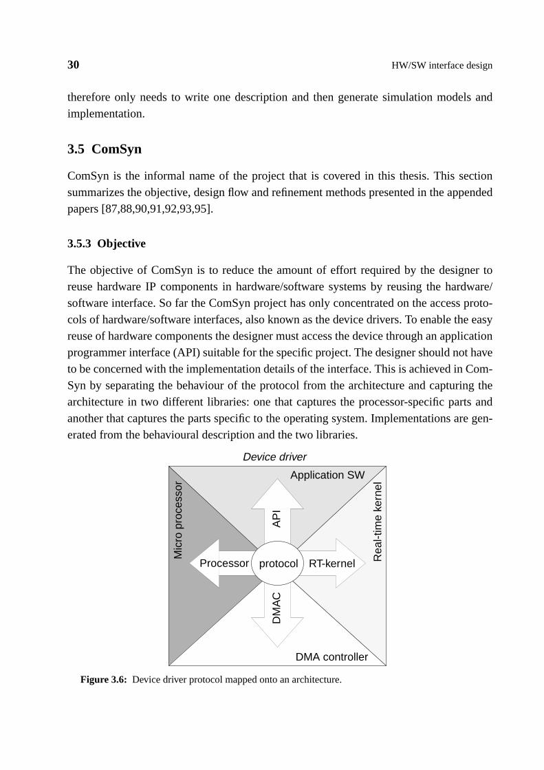
30 HW/SW interface design
therefore only needs to write one description and then generate simulation models andimplementation.
3.5 ComSyn
ComSyn is the informal name of the project that is covered in this thesis. This sectionsummarizes the objective, design flow and refinement methods presented in the appendedpapers [87,88,90,91,92,93,95].
3.5.3 Objective
The objective of ComSyn is to reduce the amount of effort required by the designer toreuse hardware IP components in hardware/software systems by reusing the hardware/software interface. So far the ComSyn project has only concentrated on the access proto-cols of hardware/software interfaces, also known as the device drivers. To enable the easyreuse of hardware components the designer must access the device through an applicationprogrammer interface (API) suitable for the specific project. The designer should not haveto be concerned with the implementation details of the interface. This is achieved in Com-Syn by separating the behaviour of the protocol from the architecture and capturing thearchitecture in two different libraries: one that captures the processor-specific parts andanother that captures the parts specific to the operating system. Implementations are gen-erated from the behavioural description and the two libraries.
DM
AC
AP
I
Processor RT-kernelprotocol
Figure 3.6: Device driver protocol mapped onto an architecture.
Device driver
Application SW
Rea
l-tim
e ke
rnel
DMA controller
Mic
ro p
roce
ssor

3.5 ComSyn 31
The information density of a device driver is very high, which is also the reason for thelow reuse and lower productivity (about four times lower) in writing device drivers com-pared with application software [20]. In essence, a device driver is an interface protocolfor synchronizing and transferring data between two parties, that is, application softwareand the interface device. The device driver can use a real-time kernel and a DMA control-ler to increase the performance of the implementation. During the implementation thedevice driver protocol therefore has to adapt to the application software, microprocessor,real-time kernel and a DMA controller (see figure 3.6). A device driver contains informa-tion on:
• processor: a device driver can have processor-specific assembler code in it. Addresscalculation for accessing device registers will also depend on the processor.
• real-time kernel: a device driver can have real-time kernel functions for synchroniza-tion, execution delay and handling of mutual exclusion.
• device: the behaviour of the device and the structure of the interface will affect thedevice driver.
• access protocol: the protocol determines how the comminution should be performed.
• API rules: determine how the communication between the device driver and the appli-cation software is performed.
• DMA controller (when DMA access is required): each DMA controller has its ownunique architecture and behaviour, that is, the device driver has to adapt its behaviourdepending on the DMA controller used.
Using ComSyn the designer only needs to model the access protocol to the device, thecentre in figure 3.6, and let the tool generate the architecturally dependent parts, that is,the arrows in figure 3.6. To further illustrate the benefits of ComSyn, one can look at theexample in figure 3.7. In this example we want to provide a library of device drivers foraccessing a device. The library is based on two access protocols, and it should supporttwo processors and two real-time kernels, as well as both DMA and non-DMA access andtwo different APIs. To write this library manually (see figure 3.7 (b)), the designer of thelibrary has to write 16 models for each protocol (that is, a total of 32 models). This doesnot include the models necessary for verification. This can of course be improved if thedevice drivers are written for reuse with the help of macros, that is, removing the depend-ence on the processor and real-time kernel. If this is done only 4 models are required foreach protocol, not counting the verification models (that is, a total of 8 models). Applyingthe same example to ComSyn one would need 2 models, each describing one access pro-

32 HW/SW interface design
tocol. From these descriptions the ComSyn tool would generate the desired implementa-tions (see figure 3.7 (a)). This also includes the generation of verification models. Onecould argue that if using ComSyn the designer needs to capture the library entries for thedifferent architectures, but this is almost the same amount of information that needs to becaptured for manually written models using macros.
3.5.4 Design flow
We model device drivers independently of the architecture using ProGram [124]. Pro-Gram is a grammar-based notation for protocol applications, which is inspired by YACC[76]. Specifications in ProGram deal with sequences of allowed events as opposed tostates and state transitions in an FSM model. In contrast to parsers for compilers ProGramallows several concurrent input and output streams. The ProGram description is synthe-sized into a set of untimed extended state machines [95,124], which is the input to thearchitecture mapping procedure described in [87] and [92].
ComSyn
LibraryLibrary
= processor 1
= processor 2
= kernel 1
= kernel 2
= With DMA
= No DMA
= API 1
= API 2
b.a.
Figure 3.7: Providing device driver implementation for two device driver protocols mapped ontotwo RT-kernels and two processors, using two different APIs, with and without DMA. (a) describesthe generation of implementation with the ComSyn approach, and (b) with a handwritten library.
protocol 1 protocol 2

3.5 ComSyn 33
There are two types of state machines: access functions and interrupt routines. As shownin figure 3.8, the mapping procedure uses data from two libraries to generate the architec-ture-specific code. The first library captures the information on the operating systemarchitecture (OSLib) and the second library captures the processor-specific characteristics(ProcLib). This organization carefully separates protocol specification from operatingsystem and processor dependencies. Using this input the tool can generate three alterna-tive implementations: (I) pure software implementation, (II) code for mixed hardware/software solutions with a DMA controller, and (III) multilevel simulation models.
3.5.5 Target architecture
As indicated in figure 3.8, our approach to device driver synthesis supports two alternativetarget architectures: (1) pure software implementation, and (2) software together with agenerated DMA controller.
Software implementation: For pure software implementation, access functions andinterrupt routines are implemented as software functions in C, which are mapped to fit theselected real-time kernel and processor. An interrupt handler is generated for the appro-priate call of the interrupt routine.
With DMA controller : The combined DMA and software-based architecture is usedwhen the designer has selected one of the state machines to be implemented as a DMA
Communication protocoldescription in ProGram
Extended FSMs
Synthesize FSMsLibrary information captured forthe supported SW architectures:– function declarations– data types– kernel functions
Library information capturedfor the supported processors:– processor-specific routines– processor characteristics– bus models
MemoryDev
ice
driv
er
Dev
ice Device
Dev
ice
driv
er
App
licat
ion
App
licat
ion
Processor Processor
Figure 3.8: Overview of the ComSyn synthesis system.
DMA controller
OSLib
Multilevel simulationmodels (see figure 3.9)
I. II.
ProcLib
Map Device Drivers ontothe specified architec-
III.

34 HW/SW interface design
controller, which controls the data transfer between a hardware device and memory. Thisis the preferred solution if high peripheral data rates must be achieved, and performanceand bus use is critical.
HW/SW simulation models: ComSyn supports the generation of three different simula-tion models (illustrated in figure 3.9): (b) hardware/software stub simulation models, (c)device drivers for hardware/software host code cosimulation, and (d) device drivers forhardware/software target code cosimulation. In stub simulation, hardware and softwareare simulated separately. For software simulation ComSyn generates a device driver thatemulates the device behaviour, and for hardware simulation it generates a testbench withthe device driver behaviour. For host code cosimulation, in which software is executed onthe host workstation and hardware simulated in an HDL simulator, ComSyn generates adevice driver that connects the software to the hardware via the HDL simulator interfaceinstead of reading and writing registers in the same way as in the implementation. Devicedrivers for target code cosimulation are the same as the ones used for implementation.
3.5.6 Protocol modelling in ProGram
A ProGram model defines the possible event sequences for several parallel inputs in termsof a grammar. Actions, which are associated with grammar rules, define the reaction to
Simulation of Systemdescription
Figure 3.9: Simulation levels in embedded hardware/software systems development: (a) systemdescription simulation, (b) HW/SW stub simulation, (c) HW/SW host code cosimulation, and (d)target code cosimulation.
Target processor code simulator HW simulator
Cosim connection Hardwarebehaviour
Processor entity connectedto cosimulation tools
Processor entity connectedto cosimulation tools
Software simulated in atarget code simulator
Real devicedriver
Cosim connection
HW simulatorCode simulated on development system
processorbus
processorbus
processorbus
Devicebehaviour
Code simulated on development system
Devicebehaviour
SW and processor accessbehaviour implemented in HW
HW simulator
a.
b.
c.
d.
System description simulation
HW/SW stub simulation
HW/SW host code cosimulation
HW/SW target code cosimulation
Software executed ina host environment
Hardware behavioursimulated in software
Cosimulationdevice driver
Software executed ina host environment
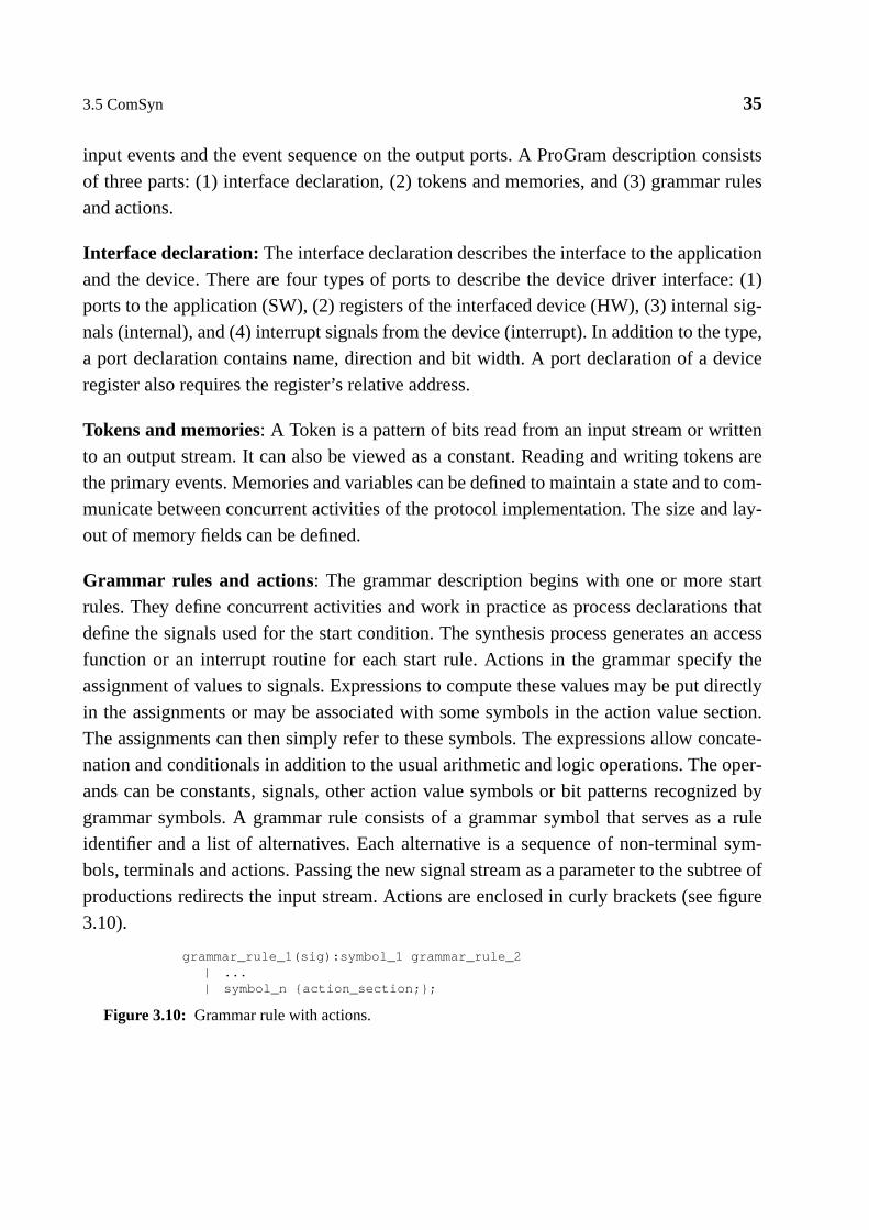
3.5 ComSyn 35
input events and the event sequence on the output ports. A ProGram description consistsof three parts: (1) interface declaration, (2) tokens and memories, and (3) grammar rulesand actions.
Interface declaration: The interface declaration describes the interface to the applicationand the device. There are four types of ports to describe the device driver interface: (1)ports to the application (SW), (2) registers of the interfaced device (HW), (3) internal sig-nals (internal), and (4) interrupt signals from the device (interrupt). In addition to the type,a port declaration contains name, direction and bit width. A port declaration of a deviceregister also requires the register’s relative address.
Tokens and memories: A Token is a pattern of bits read from an input stream or writtento an output stream. It can also be viewed as a constant. Reading and writing tokens arethe primary events. Memories and variables can be defined to maintain a state and to com-municate between concurrent activities of the protocol implementation. The size and lay-out of memory fields can be defined.
Grammar rules and actions: The grammar description begins with one or more startrules. They define concurrent activities and work in practice as process declarations thatdefine the signals used for the start condition. The synthesis process generates an accessfunction or an interrupt routine for each start rule. Actions in the grammar specify theassignment of values to signals. Expressions to compute these values may be put directlyin the assignments or may be associated with some symbols in the action value section.The assignments can then simply refer to these symbols. The expressions allow concate-nation and conditionals in addition to the usual arithmetic and logic operations. The oper-ands can be constants, signals, other action value symbols or bit patterns recognized bygrammar symbols. A grammar rule consists of a grammar symbol that serves as a ruleidentifier and a list of alternatives. Each alternative is a sequence of non-terminal sym-bols, terminals and actions. Passing the new signal stream as a parameter to the subtree ofproductions redirects the input stream. Actions are enclosed in curly brackets (see figure3.10).
grammar_rule_1(sig):symbol_1 grammar_rule_2| ...| symbol_n {action_section;};
Figure 3.10: Grammar rule with actions.

36 HW/SW interface design

4 Summary of papers
The eight papers in this thesis can be categorized in four groups: (section 4.1) analysisand problem formulation, (section 4.2) specification of interface protocols, (section 4.3)synthesis of interface protocols, and (section 4.4) validation of interface protocols. Sec-tions 4.1 to 4.4 outline the content and contribution of each paper. The content of eachpaper is identified in the design flow of our device driver synthesis tool, ComSyn,depicted in figure 4.1. Section 4.5 presents an outline of each author’s contribution to thepapers.
4.1 Analysis and problem formulation
4.1.1 Paper 1, Norchip 1997
This paper formulates the problem of communication synthesis in hardware/softwareembedded systems (a) by investigating the required concepts at the specification level and(b) by analysing potential communication routes in heterogeneous hardware/software
Extended FSMs
Synthesize FSMs
MemoryDev
ice
driv
er
Dev
ice
Device
Dev
ice
driv
er
App
licat
ion
App
licat
ion
Processor Processor
Figure 4.1: Identification of paper contents in the ComSyn design flow.
DMA controller
OSLib
Multilevel simulationmodels
ProcLib
Map Device Drivers ontothe specified architec-
Paper 1
Papers 3 & 5
Papers 4 & 5
Papers 6 & 7
Paper 8
Paper 2Communication protocoldescription in ProGram
38 Summary of papers
architectures, thereby defining the input and output for communication synthesis. We alsoformulate a taxonomy for a complete classification of communication in hardware/soft-ware embedded systems.
4.1.2 Paper 8, Norchip 1998
This paper compares four different approaches to the specification and refinement of soft-ware parts in a hardware/software communication channel with respect to design produc-tivity. The four approaches are CoWare [21], MakeApp [57], ComSyn [87,95,88,92] andmanual refinement. This case study shows how the different tools can improve the designprocess. It also shows the deficiencies of the different approaches. The comparison isdone by analysing the impact different techniques have on the design process. The analy-sis is based on two designs: a channel decoder of a transceiver in a D-AMPS base stationand an operation and maintenance block of an ATM network. We compare design produc-tivity by comparing the amount of effort required for development, validation and librarymaintenance.
4.2 Protocol description
4.2.3 Paper 2, Euromicro 1998
This paper presents an adaptation of the interface specification language ProGram to cap-ture hardware/software interfaces, that is, device drivers and bus interfaces. ProGram isused for the architecturally independent modelling of device drivers and bus interfaces formixed hardware/software systems. The specification of the protocol is separated from thedescription of processor bus interfaces and operating system device driver interfaces,which ensures high efficiency in device driver development and maintenance. A devicedriver synthesis method for single threaded architectures is presented together with theresults of modelling and implementation efficiency for both device drivers and bus inter-faces.
4.3 Protocol synthesis
4.3.4 Paper 3, DATE 1999
This paper presents a method for generating the software parts of a hardware/softwareinterface (that is, the device drivers), which separates the behaviour of the interface fromthe architecture-dependent parts. The generation procedure targets a real-time kernel-

4.4 Protocol validation 39
based architecture. The synthesis procedure presented uses a ProGram protocol descrip-tion and two libraries as input. The first library captures the processor-specific parts andthe second captures the operating system kernel parts. The paper also presents an analysisand specification of the contents for the two libraries.
4.3.5 Paper 4, VLSI Design 1999
This paper presents a protocol synthesis method that generates a mixed hardware andsoftware implementation, that is, a complement to the approach in paper 3. For the hard-ware part, the synthesis method will generate an application-specific DMA controller foreach synthesized protocol specification. The software parts of the generated implementa-tion are components for the initialization and synchronization of and communication withthe DMA controller. Since this approach is based on a device driver synthesis system forsoftware solutions (in paper 3), which adapts the device drivers generated to a selectedprocessor and kernel, the generated hardware/software solution can also be adapted to anyprocessor and OS kernel.
4.3.6 Paper 5, Kluwer DAES Submitted 1999
This paper presents an improvement of the approaches proposed in papers 3 and 4. Theimprovements are:
• Improved description of the synthesis procedures.
• Improved software synthesis procedure.
• DMA controller synthesis extended to handle access functions.
• Wider range of examples applied to the synthesis procedures.
• Complexity analysis of the synthesis methods.
4.4 Protocol validation
4.4.7 Paper 6, HLDVT 1998
This paper presents a multiphase validation approach that facilitates the simulation ofinterfaces at several steps during development. The technique is base on the generation ofsimulation models from an interface protocol description. The presented validationmethod keeps the simulation models consistent with both the specification and the imple-mentation by generating the models with a technique derived from interface synthesis (in

40 Summary of papers
Table 4.1: Author’s contribution to each individual paper (M = main contributor, C = co-author).
Paper #Author contribution
ContributionMOa AJb JÖc
1 M C MO : Analysis of communication in embedded systems.
MO : A taxonomy for classification of communication.
AJ: Supervisor.
2 M C C MO & JÖ: Adaptation of ProGram to specification ofHW/SW interface with ProGram.
MO : A method for generating SW code for single-threaded software.
AJ: Supervisor.
3 M C MO : Analysis and proposal of library structure for cap-turing architecturally dependent parts of device drivers.
MO : SW code generation methods for real-time kernel-based embedded systems.
AJ: Supervisor.
4 M C MO : Proposal of a DMA architecture for synthesis.
MO : A DMA controller synthesis method.
AJ: Supervisor.
5 M C MO : Improved description of the synthesis procedures.
MO : DMA controller synthesis expanded to handleaccess functions.
MO : Wider range of example applied to the methods.
MO : Complexity analysis.
AJ: Supervisor.
6 M C MO : Multilevel validation technique based ongenerated simulation models.
AJ: Supervisor.
7 M C MO : Adaptation of the validation approach to valida-tion of HW/SW interfaces in IP-based design.
AJ: Supervisor.
8 M C MO : A comparison between three differentapproaches with ours.
MO & AJ: Case studies.
AJ: Supervisor.
a. Mattias O’Nilsb. Axel Jantschc. Johnny Öberg
4.5 Author’s contributions 41
papers 3 and 5). This method enables the interface specification, simulation models andimplementation to be consistent with each other. The paper shows that several validationphases are justified (a) by the faster simulation of early phases (up to four times fasterthan late phases), and (b) by allowing both hardware designers and software developers towork in their familiar tool environments as long as possible.
4.4.8 Paper 7, IPSDP 1998
This paper applies the approach taken in paper 6 to the verification of the interface proto-cols used for IP components in IP-based design. The method of generating simulationmodels results in significantly less effort being required to verify interfaces between soft-ware and IP components.
4.5 Author’s contributions
The contribution of the author of this thesis has been essential to all the papers presentedin the thesis. The exact contribution of each author is described in table 4.1. As describedabove, these papers cover the analysis, refinement, design and verification of hardware/software interfaces.

42 Summary of papers

5 Thesis summary
Aspects of modelling, synthesis and validation of hardware/software interfaces for loweffort reuse have been studied and analysed in this thesis. Sections 2 and 3 give an exten-sive review of the related work. Section 3 also gives a motivation for the work togetherwith a summary of the work presented in the eight appended papers. Section 4 identifiesthe original contribution for each paper.
The following section summarizes the conclusions reached during work on this thesis,followed by suggestions for improvements of the approach presented.
5.1 Conclusions
Paper 1 [89] presents an approach to the classification of communication within systemspecifications. It also defines the solution space and problem formulation of communica-tion synthesis for embedded hardware/software systems. The problem formulation worksas a base for the work covered by this thesis.
The thesis presents an approach to the generation of hardware/software interfacesbetween application software and hardware IP components. This approach reduces theeffort required in designing the hardware/software interfaces to the generation time of theinterface (see paper 5 [91]). The reuse and generation of device drivers is enabled bymodelling the interface protocols using an architecture- and implementation-independentdescription (ProGram) (see paper 2 [95]). ProGram is a grammar-based notation extendedto model device drivers. The protocol description contains less information than compara-ble models in C because no architectural information is captured in the protocol. Resultsfrom the modelling of design examples indicate that the size of the grammar-baseddescription is half that of an ordinary C description (see papers 2, 3, 5 and 8[95,92,91,90]).
Methods for translating the protocol description into software implementation are pre-sented (see papers 2, 3 and 5 [95,92,91]), as well as into a DMA-based implementation(see papers 4 and 5 [87,91]). Results from these methods show that the performance (exe-
44 Thesis summary
cution time) and size (code size) for these are similar to those modelled by hand in C (seepaper 5 [91]).
Papers 6 and 7 [88,93] present methods for the generation of hardware/software co-verifi-cation models. These models can be generated for three levels of abstraction, each leveldiffers in the details covered and simulation speed. The highest level of abstraction (stubsimulation) gives up to four-times higher simulation performance and allows hardwareand software developers to work in their familiar tool environments. The approach leadsto better consistency between specification and implementation/simulation models for allabstraction levels, since all models are generated from the same protocol description.
5.2 Future work
5.2.1 Specification
ProGram is the grammar-based description language used to describe communicationprotocols. The initial target for ProGram was to capture protocols that were intended forhardware implementations. In this thesis, ProGram has been adapted to capture interfaceprotocols intended for a hardware/software implementation. Although ProGram has beenadapted to model hardware/software interface protocols, it still requires awkward descrip-tions to model certain behaviours, for example, unbounded loops and buffers.
Task: Learn from the results and do a thorough analysis of device drivers, and from thisimprove the description language.
5.2.2 Synthesis
The synthesis procedure presented here starts from where the synthesis procedure forhardware [124] has generated a set of FSMs. The translation from ProGram to statemachines is done with a hardware implementation in mind. The FSMs are then trans-formed and optimized for software or DMA-based implementation. As shown in this the-sis, the quality of the generated code is similar to that for handwritten code with respect toperformance and size. It is likely that the code quality will increase if the translationsfrom specification to implementation are merged, that is, translation from ProGram toFSMs would be optimized for device driver synthesis. In addition, heuristics for the trad-ing of size and performance of the generated code could be applied.

5.2 Future work 45
Task: Merge the tasks of protocol description synthesis, architectural mapping and codegeneration by developing new methods for translating from description to FSMs.
5.2.3 Target architecture
As presented in this thesis, the methods for architectural mapping only support a simplebus architecture, as found in an embedded system. No work has been done to study thegeneration of device drivers for more complex systems with standard buses such as PCI[99] or SBus [106].
Task: Analyse the requirements for device drivers in a standard bus structure such as PCIand SBus, that is, multibus structure. Improve the library structure and the architecturalmapping procedures to handle multibus architectures.
The generation of application-specific DMA controllers presented in this thesis supportsonly a read/write architecture. That is, if data is moved from source A and moved to sinkB, the DMA controller first has to read the data from A and then write the data to B. Mostoff-the-shelf DMA controllers supports awrite-throughmode, that is, the DMA controllerwrites to B at the same time as it reads A. This performance improvement comes at thecost of changes to the implementation since the DMA controller has to control the sink Binstead of having B controlled from the bus.
Task: Improve the methods for generating application-specific DMA controllers to han-dle write-through operation.
The granularity of parts of the protocol that can be implemented as a DMA controller isdefined by whole access functions or interrupt handlers. This is not always the optimalsolution since the data dependencies in the access functions can cause several bus opera-tions.
Task: Develop methods for partitioning device driver behaviour between software imple-mentation and DMA controller implementation to fit a set of performance and cost con-straints.

46 Thesis summary

6 References
[1] 256 Mbit SDRAM - 16M x 4 bit x 4 Banks Synchronous DRAM, Data sheetKM416S16230A, Rev. 0.2. Samsung Electronics Inc., January 1999.
[2] 80C51-based 8-bit microcontrollers, Philips Semiconductors, Netherlands, 1997.
[3] M. Abramovici, M. A. Bruer, A. D. Friedman,Digital Systems Testing and TestableDesign, Rockville, Computer Science Press, 1990.
[4] Advanced RISC Machines (ARM) Ltd., 90 Fulbourn Road, CAMBRIDGE, Cam-bridgeshire, CB1 9JN, England.
[5] M. Afghahi and C. Svensson, “Performance of synchronous and asynchronousschemes for VLSI systems”,IEEE Transactions on Computers, Vol. 41, No. 7, pp.858-872, July 1992.
[6] P. Ainsley, “The Embedded Micro Controller ASIC”,Proceedings of the Interna-tional Workshop on IP Based Synthesis and System Design, pp. 97-100, 1998.
[7] A. Allara, S. Filipponi, W. Fornaciari, F. Salice, D. Sciuto, “A Flexible Model forEvaluating the Behavior of Hardware/Software Systems”Proceedings of the 5thInternational Workshop on Hardware/Software Codesign, March 1997.
[8] P. M. Athanas, H. F. Silverman, “Processor Reconfiguration Through Instruction-Set Metamorphosis”,IEEE Computer, 1993.
[9] H. B. Bakoglu,Circuits, Interconnections, and Packaging for VLSI, Addison-Wes-ley Publishing Company, ISBN 0-201-06008-6, 1990.
[10] F. Balarin, M. Chiodo, P. Giusto, H. Hsieh, A, Jurecska, L. Lavagno, C. Passerone,A. Sangiovanni-Vincentelli, E. Sentovich, K. Suzuki, B. Tabbara,Hardware-Soft-ware Co-Design of Embedded Systems: The Polis Approach., Kluwer AcademicPress, 1997.
[11] A. Balboni, W. Fornaciari, D. Sciuto, “Co-synthesis and Co-simulation of Control-Dominated Embedded Systems”,Design Automation for Embedded Systems, Vol. 1,No. 3, pp. 257-289, 1996.
48 References
[12] A. Balboni, W. Fornaciari, D. Sciuto, “Partitioning and Exploration Strategies in theTOSCA Co-Design Flow”,Proceedings of the 4th International Workshop on Hard-ware/Software Codesign, March 1996.
[13] P. Bannon, “Alpha EV7: A Scalable Single-chip SMP”,MicroProcessor Forum,October 1998.
[14] E. Barros, W. Rosenstiel, X. Xiong, “A method for partitioning UNITY language inhardware and software”,Proceedings of the European Design Automation Confer-ence, 1994.
[15] D. L. Barton, S. C. Fortier, “Using a systems description language for complete avi-onics systems”,Proceedings of the IEEE Aerospace Conference, pp. 249-254, 1998.
[16] S. S. Battacharyya, J. T. Buck, S. Ha, E. A. Lee, “Generating compact code fromdataflow specifications of multirate signal processing algorithms”,IEEE Transac-tion on Circuits and Systems, Vol. 42, No. 3, pp. 138-150, 1995.
[17] L. Benini, G. De Micheli,Dynamic Power Management of Circuits and Systems:Design Techniques and CAD Tools, Kluwer, 1997.
[18] Th. Benner, R. Ernst, A. Österling, “Scalable Performance Scheduling for Hard-ware-Software Cosynthesis”,Proceedings of the European Design Automation Con-ference, 1995.
[19] Th. Benner, J. Henkel, R. Ernst, “Internal Representation of Embedded Hardware-/Software-Systems”,Proceedings of the 1st International Workshop on Hardware/Software Codesign, 1993.
[20] B. Bohem, B. Clark. E. Horowitz, C. Westland, R. Madachy, R. Selby, “Cost modelsfor future software life cycle processes: COCOMO 2.0”,Annals of Software Engi-neering, Vol. 1, pp. 57-94, 1995.
[21] I. Bolsens, H. J. De Man, B. Lin, K. van Rompaey, S. Vercauteren, D. Verkest,“Hardware/Software Co-Design of Digital Telecommunication Systems”,Proceed-ings of the IEEE, Vol. 85, No. 3, pp. 391-418, 1997.
[22] R. Brodersen, A. Chandrakasan, S. Sheng, “Design Considerations for Portable Sys-tems,”IEEE International Solid-state Circuits Conference, February 1993.
[23] R. Camposano, J. Wilberg, “Embedded System Design”,Design Automation forEmbedded Systems, Kluwer Academic Publisher, Vol. 1, No. 1-2, March, pp. 5-50,1997.
49
[24] R. Camposano, W. Wolf,High-Level VLSI Synthesis, ISBN 0-7923-9159-4, KluwerAcademic Publishers, 1991.
[25] S. Cardelli, M. Chiodo, P. Giusto, A. Jurecska, L. Lavagno, C. Sansoè, A. Sangio-vanni-Vincentelli, “Rapid-Prototyping of Embedded Systems via ReprogrammableDevices”,Design Automation for Embedded Systems, Kluwer Academics Publisher,Vol. 3, No. 2/3, pp. 149-162, March 1998.
[26] A. Chandrakasan, S. Sheng, R.W. Brodersen, “Low-Power CMOS Digital Design,”IEEE Journal of Solid-State Circuits, Vol. 27, No. 4, pp. 473-484, April 1992.
[27] E. Charbon, I. Torunoglu, “Intellectual Property Protection Via Hierarchical Water-marking”, Proceedings of the International Workshop on IP based Synthesis andSystem Design, 1998.
[28] M. Chiodo, P. Giusto, A. Jurecska, M. Marelli, “A Formal Specification Model forHardware/Software Codesign”,Proceedings of the 1st International Conference onHardware/Software Codesign, 1993.
[29] P. Chou, K. Hines, K. Partridge, G. Borriello, “Control generation for embeddedsystems based on composition of modal processes”,Proceedings of the Interna-tional Conference on Computer Aided Design, 1998.
[30] P. H. Chou, R. B. Ortega, G. Borriello, “The Chinook Hardware/Software Co-Syn-thesis System”,Proceedings of the International Symposium on System Synthesis,1995.
[31] P. H. Chou, R. B. Ortega, G. Borriello, “Synthesis of the Hardware/Software Inter-face in Microcontroller-Based Systems”,Proceedings of the International Confer-ence on Computer Aided Design, pp. 488-495, 1992.
[32] P. Chou, E. A. Walkup, G. Borriello, “Scheduling for reactive real-time systems”,IEEE Micro, Vol. 14, No. 4, pp. 37-47, August 1994.
[33] Computer on a Chip,IEEE Computer, January, 1971.
[34] Control Design Automation Solution, The MathWorks Inc., Watertown, MA, USA.
[35] CORBA/IIOP 2.2 Specification, Object Management Group, Inc., 492 Old Connecti-cut Path Framingham, MA 01701, USA, 1998.
[36] J-M Daveau, G. F. Marchioro, T. Ben Ismail, A. A. Jerraya, “Protocol Selection andInterface Generation for HW-SW Codesign”,IEEE Transaction on Very Large ScaleIntegration, Vol. 5, No. 1, pp. 136-144, 1997.

50 References
[37] J. Davis, R. Galicia, M. Goel, C. Hylands, E.A. Lee, J. Liu, X. Liu, L. Muliadi, S.Neuendorffer, J. Reekie N. Smyth, J. Tsay and Y. Xiong,Heterogeneous ConcurrentModeling and Design in Java, Memorandum UCB/ERL M98/72, EECS, Universityof California, Berkeley, CA, USA 94720, November 23 1998.
[38] A. E. K. Dekdouk, O. Ait-Mohamed, M. S. Jahan, E. Cerny, “What About FormalVerification of IP-based SoC Designs?”,Proceedings of the International Workshopon IP based Synthesis and System Design, 1998.
[39] S. Devadas, A. Ghosh, K. Keutzer,Logic Synthesis, ISBN 0-07-016500-9, McGraw-Hill Inc., 1994.
[40] J. C. Días, J. Riesco, P. Plaza, “Design of an ARM based System-on-a-Chip for PayPhones”,Proceedings of the International Workshop on IP Based Synthesis and Sys-tem Design, pp. 101-105, 1998.
[41] P. Dreike, J. McCoy, “Co-Simulating Software and Hardware in Embedded Sys-tems“,Embedded Systems Programming, Vol. 10, No. 6, June 1997.
[42] DSP Workshop, The MathWorks Inc., Watertown, MA, USA.
[43] Eagle Tools, Synopsys Inc., 700 East Middlefield Rd. Mountain View, CA 94043,USA.
[44] W. Ecker, M. Glesner, A. Vombach, “Protocol Merging: A VHDL-Based Methodfor Clock Cycle Minimizing and Protocol Preserving Scheduling of IO-Operations”,Proceedings of the European Design Automation Conference, pp. 624-629, 1994.
[45] M. Edvards, J. Forrest, “A Development Environment for the Co-synthesis ofEmbedded Software/Hardware Systems”,Proceedings of ED & TC, E-DAC,EUROASIC, pp. 469-473, 1994.
[46] S. Edwards, L. Lavagno, E. A. Lee, A. Sangiovanni-Vincentelli, “Design of Embed-ded Systems: Formal Models, Validation, and Synthesis”,Proceedings of the IEEE,Vol. 85, No. 3, pp. 366-390. March 1997.
[47] M. Eisenring, J. Teich, “Domain-Specific Interface Generation from Dataflow Spec-ifications”, Proceedings of the 6th International Workshop on Hardware/SoftwareCodesign, pp. 43-47, 1998.
[48] P. Eles, Z. Peng, K. Kuchinski, A Doboli, “System Level Hardware/Software Parti-tioning Based on Simulated Annealing and Tabu Search”,Design Automation forEmbedded Systems, Kluwer Academic Publisher, Vol. 2, No. 1, pp. 5-32, 1997.

51
[49] R. Ernst, J. Henkel, Th. Benner, “Hardware-Software Cosynthesis for Microcontrol-lers”, IEEE Design and Test of Computers, December 1993.
[50] R. Ernst, Th. Benner,Communication, Constraints and User Directives inCOSYMA, Technical Report CY-94-2, Institut für DV-Anlagen, Technische Univer-sität Braunschweig, 1994.
[51] J. Fleischmann, K. Buchenrieder, R. Kress, “Codesign of Embedded Systems Basedon Java and Reconfigurable Hardware Components”,Proceedings of Design, Auto-mation and Test in Europe Conference (DATE), pp. 768-769, March 1999.
[52] W. Fornaciari, P. Gubian, D. Sciuto, C. Silvano, “Power estimation of embeddedsystems: a hardware/software codesign approach”,IEEE Transaction on VLSI Sys-tems, Vol. 6, No. 2, pp. 266-275, June 1998.
[53] R. Foster, “A Design Style to simplify IP Integration and Verification”,Proceedingsof the International Workshop on IP Based Synthesis and System Design, pp. 39-44,1998.
[54] D. Gajski, A. Wu, N. Dutt, S. Lin,High-Level Synthesis, ISBN 0-7923-9194-2,1992.
[55] D. Gajski, F. Vahid, S. Narayan, and J. Gong,Specification and Design of EmbeddedSystems, Prentice Hall, 1994.
[56] J. Gong, D. D. Gajski, A. Nicolau, “A performance evaluator for parameterizedASIC architectures”,Proceedings of the European Design Automation Conference,pp. 66-71, 1994.
[57] R. Grehan, “Driver Assistance”,Computer design, vol. 36, no. 1, pp. 75-80, 1997.
[58] R. K. Gupta,Co-Synthesis of Hardware and Software for Digital Embedded Sys-tems, PhD Thesis, Stanford, Dec. 1993.
[59] N. Halbwachs,Synchronous Programming of Reactive Systems, Kluwer AcademicPublishers, 1993.
[60] W. Hardt, W. Rosenstiel, “Prototyping of Tightly Coupled Hardware/Software Sys-tems”,Design Automation for Embedded Systems, Kluwer Academic Publisher, Vol.2, No. 3/4, pp. 283-318, May 1997.
[61] A.Hemani, T.Meincke, P.Nilsson, T.Olsson, S.Kumar, P.Ellervee,J.Öberg, A.Pos-tula, “Lowering power consumption in clock by using Globally Asynchronous,Locally Synchronous Design Style”,Proceedings of the 36th Design AutomationConference, June 1999.

52 References
[62] J. Henkel, R. Ernst, U. Holtmann, Th. Benner, “Adaptation of Partitioning and High-Level Synthesis in Hardware/Software Co-Synthesis”,Proceedings of InternationalConference on Computer Aided Design, pp. 96-100, 1994.
[63] J. Hou, W. Wolf, “Partitioning methods for hardware-software co-design”,Proceed-ings of the 4th International Workshop on Hardware/Software Codesign, pp. 70-76,1996.
[64] G. P Hyatt, United State Patent, Pat. no. 4 942 516, July, 1990.
[65] I2C Peripherals for Microcontrollers, Philips Semiconductors, 1992.
[66] T. Ben Ismail, M. Abid, A. Jerraya, “COSMOS: A CoDesign Approach for Commu-nicating Systems”,Proceedings of 2nd International Workshop on Hardware/Soft-ware Codesign, 1994.
[67] T. Ben Ismail, K. O’Brien, A. A. Jerraya, “Interactive System-level Partitioning withPARTIF”, Proceedings of the European Design Automation Conference, Paris,France, pp. 464-468, Feb. 1994.
[68] INTEGRATION: The VLSI Journal, Quarterly, North Holland Publishing, Amster-dam, Netherlands.
[69] A. Jantsch, P. Ellervee, J. Öberg, A. Hemani and H. Tenhunen, “Hardware-SoftwarePartitioning and Minimizing Memory Interface Traffic”, Proceedings of the Euro-pean Design Automation Conference, pp. 226-231, 1994.
[70] A. Jantsch, J. Isoaho, “A Versatile Design Validation Environment by Means ofSoftware Execution, Hardware Simulation, and Emulation”,Proceedings of the 36thSIMS Simulation Conference, pp 322-325, 1994.
[71] A. Jantsch, S. Kumar, I. Sander, B. Svantesson, J. Öberg, and A. Hemani, “Compar-ison of Six Languages for System Level Descriptions of Telecom Systems”,Pro-ceedings of the Forum on Design Languages, vol. 2, pp 139 - 148, 1998.
[72] A. Jantsch, J. Öberg, P. Ellervee, A. Hemani, H. Tenhunen, “A software orientedapproach to hardware-software co-design”,Proceedings of the International Con-ference on Compiler Construction, pp. 93-102, 1994.
[73] JavaBeans - Specification, Sun Microsystems, Inc., 901 San Antonio Rd., Palo Alto,CA 94303 USA, 1998.
[74] A. A. Jerraya, K. O'Brien, “SOLAR: An Intermediate Format for System-LevelModeling and Synthesis”,Computer Aided Software/Hardware Engineering, Ed. J.Rozenblit, IEEE Publisher, chap. 10, 1994.

53
[75] H. Jifeng, I. Page, J. Bowen,Towards a Provably Correct Hardware Implementationof OCCAM, Technical Report, Oxford University Computing Laboratory, 1994.
[76] S. C. Johnsson,Yet another compiler compiler, Computing Science Tech. Rep. 32,AT&T Bell Lab. Murray Hill, 1975.
[77] L. Lavagno, J. Cortadella, A. Sangiovanni-Vincentelli, “Embedded code optimiza-tion via common control structure detection”,Proceedings of the 5th InternationalWorkshop on Hardware/Software Codesign, March 1997
[78] T. Lee,The Design of CMOS Radio-Frequency Integrated Circuits, Cambridge Uni-versity Press, 1998.
[79] C. Liem, P. Paulin, A. Jerraya, “Compilation Methods for the Address CalculationUnits of Embedded Processor Systems”,Design Automation for Embedded Systems,Kluwer Academic Publisher, Vol. 2, No. 1, pp. 61-78, January 1997.
[80] B. Lin, S. Vercauteren, “Synthesis of Concurrent System Interface Modules withAutomatic Protocol Conversion Generation”,Proceedings of the International Con-ference on Computer Aided Design, pp. 101-108, 1994.
[81] J. Madsen, J. Grode, P. V. Knudsen, M. E. Petersen, A. Haxthausen, “LYCOS: theLyngby Co-Synthesis System”,Design Automation for Embedded Systems, KluwerAcademic Publisher, Vol. 2, No. 2, March, pp. 195-235, 1997.
[82] G. De Micheli, R. K. Gupta, “Hardware/Software Co-Design”,Proceedings of theIEEE, Vol. 85, No. 3, pp. 349-365, March 1997.
[83] G. De Micheli, D. C. Ku, F. Mailhot, T Truong, “The OLYMPUS Synthesis Systemfor Digital Design”, IEEE Design & Test of Computers, Vol. 7, No. 5, pp. 37-53,1990.
[84] L. Mittag, “Device Drivers for Nonexistent Devices”,Embedded System Program-ming, Aug. 01 1996, vol. 9, no. 8, pp. 30-32,34,36,38,40.
[85] P. Moeschler, H. P. Amann, F. Pellandini, “High-Level Modeling using ExtendedTiming Diagrams, A formalism for the behavioral specification of digital hardware”,Proceedings of the European Design Automation Conference, pp. 494-499, 1992.
[86] R. Niemann, P. Marwedel, “Synthesis of Communicating Controllers for ConcurrentHardware/Software Systems”,Proceedings of the Design Automation and Test inEurope Conference (DATE), pp. 912-913, 1998.

54 References
[87] M. O’Nils, A. Jantsch, “Synthesis of DMA Controllers from Architecture Independ-ent Descriptions of HW/SW Communication Protocols”,Proceedings of the IEEEVLSI Design Conference, pp. 138-145, 1999.
[88] M. O’Nils, A. Jantsch, “Multi-phase Validation of Hardware/Software Interfacesbased on Generated Simulation Models“,Proceedings of the IEEE Workshop onHigh Level Design, Validation and Test, November, 1998.
[89] M. O’Nils, A. Jantsch, “Communication in Hardware/Software Embedded Systems- A Taxonomy and Problem Formulation”,Proceedings of the 15th IEEE NorchipConference, pp. 67-74, 1997.
[90] M. O’Nils, A. Jantsch, “Refinement of HW/SW Communication Channels: CaseStudy and Comparison”,Proceedings of the 16th IEEE Norchip Conference, pp.230-237, 1998.
[91] M. O’Nils, A. Jantsch, “Device Driver and DMA Controller Synthesis from HW/SW Communication Protocol Specifications”, submitted toDesign Automation forEmbedded Systems, Kluwer Academics Publisher, 1999.
[92] M. O’Nils, A. Jantsch, “Operating System Sensitive Device Driver Synthesis fromImplementation Independent Protocol Specification”,Proceedings of the DesignAutomation and Test in Europe Conference (DATE), Germany, pp. 562-567, March1999.
[93] M. O’Nils, A. Jantsch, “HW/SW Interface Validation in IP based System Design”,Proceedings of the International Workshop on IP based Synthesis and SystemDesign, pp. 79-84, 1998.
[94] M. O’Nils, A. Jantsch, A. Hemani, H. Tenhunen, “Interactive Hardware-SoftwarePartitioning and Memory Allocation Based on Data Transfer Profiling”,Proceed-ings of the International Conference on Recent Advances in Mechatronics, pp. 447-452, 1995.
[95] M. O’Nils, J. Öberg, A. Jantsch, “Grammar Based Modelling and Synthesis ofDevice Drivers and Bus Interfaces“,Proceedings of the Euromicro Conference, pp.55-58, August, 1998.
[96] B. Oelmann,Design and performance evaluation of asynchronous micropipelinecircuits for digital radio, Lic. thesis, ISSN 1104-8697, Royal Institute of Technol-ogy, Stockholm, Sweden, 1996.
[97] R. B. Ortega, G. Borriello, “Communication Synthesis for Distributed EmbeddedSystems”,Proceedings of the International Conference on Computer Aided Design,1998.

55
[98] R. B. Ortega, L. Lavagno, G. Borriello, “Models and methods for HW/SW intellec-tual property interfacing”, NATO ASI on System-level Synthesis, 1998.
[99] PCI Specification, Version 2.2, PCI Special Interest Group, Oregon, USA, 1999.
[100]R. Passerone, J. A. Rowson, “Automatic Synthesis of Interfaces between Incompati-ble Protocols”,Proceedings of the 35th Design Automation Conference, June 1998.
[101]Pentium II Processor Developer’s Manual, Intel Inc., October 1997.
[102]PowerPC - MPC 750 RISC Microprocessor Technical Summary, Motorola Inc.,1997.
[103]Renoir - Reference Manual, Mentor Graphics Corporation, 1998.
[104]J. Rowson, A. Sangiovanni-Vincentelli, “Felix initiative pursues new codesignmethodology”,Electronic Engineering Times, pp. 50,51, 74, June 1998.
[105]M. Santarini, “French allies to blend CASE, EDA in SoC tool”,Electronic Engi-neering Times, Issue: 1035, November 1998.
[106]SBus Specification, IEEE Std 1496-1993, 1993.
[107]Seamless Co-Verification Environment User’s and Reference Manual, Ver. 2.3,Mentor Graphics Inc., 1998.
[108]G. C. Sih, E. A. Lee, “Declustering: a new multiprocessor scheduling of periodic,real-time tasks”,IEEE Transaction on Parallel and Distributed Computing, Vol. 4,No. 6, pp. 625-637, June 1993.
[109]A. Smailagic, D. P. Siewiorek, R. Martin, J. Stivoric, “Very Rapid Prototyping ofWearable Computers: A Case Study of Custom versus Off-the-Shelf Design Meth-odologies,Design Automation for Embedded Systems, Vol. 3, No. 2/3, pp. 217-230,March 1998.
[110]J. A. Stankovic, M. Spuri, M. Di Natale, G. C. Buttazzo, “Implications of classicalscheduling results for real-time systems,”,IEEE Computer, Vol. 28, No. 6, pp. 16-25, June 1995.
[111]K. Tammemäe, M. O'Nils, A. Hemani, “Flexible Codesign Target Architecture forEarly Prototyping of CMIST Systems”,Field-Programmable Logic Smart Applica-tion, New Paradigms and Compilers, Springer-Verlag, ISBN 3-540-61730-2,pp.193-199, 1996.
[112]E. Tuggle, “Writing Device Drivers”,Embedded Systems Programming, Jan. 1993,pp. 42-65.

56 References
[113]F. Vahid, J. Gong, D. D. Gajski, “A binary-constraint search algorithm for minimiz-ing hardware during hardware/software partitioning”,Proceedings of the EuropeanDesign Automation Conference, 1994.
[114]C. Valderrama, F. Naçabæl, P. Paulin, A. Jerraya, “Automatic VHDL-C InterfaceGeneration for Distributed Cosimulation: Application to Large Design Examples”,Design Automation for Embedded Systems, Kluwer Academic Publisher, Vol. 3, No.2/3, pp. 199-216, March 1998.
[115]S. Vercauteren, B. Lin, “Hardware/Software Communication and System Integra-tion for Embedded Architectures“,Design Automation for Embedded Systems, Klu-wer Academic Publisher, Vol. 2, No. 3/4, pp. 359-382, May 1997.
[116]S. Vercauteren, D. Verkest, J. Van Der Steen, “Combining Software Synthesis andHardware/Software Interface Generation to Meet Hard Real-Time Constraints”,Proceedings of Design, Automation and Test in Europe Conference (DATE), pp.556-561, March 1999.
[117]VSI Alliance - Architecture Document, Version 1.0, 1997.
[118]W. H.Wolf, “Hardware-Software Co-Design of Embedded System”,Proceedings ofthe IEEE, vol. 82, no. 7, July 1994.
[119]T. Y. Yen, W. Wolf, “Performance estimation of distributed embedded systems”,Proceedings of the International Conference on Computer Design, 1995.
[120]J. S. Young, J. MacDonald, M. Shilman, A. Tabbara, P. Hilfinger, A R. Newton,“Design and Specification of Embedded Systems in Java Using Successive, FormalRefinement”,Proceedings of the 35th Design Automation Conference, 1998.
[121]H. Zeltwanger, “An inside look at the fundamentals of CAN,Control Engineering,42(1), January 1995.
[122]J. Zhu, R. Dömer, D. D. Gajski, “Syntax and Semantics of the SpecC Language”,Proceedings of the Synthesis and System Integration of Mixed Technologies, Decem-ber 1997.
[123]J. Zhu, D. D. Gajski, “A Retargetable, Ultra-fast Instruction Set Simulator“,Pro-ceedings of the Design Automation and Test in Europe Conference (DATE), pp. 298-302, March 1999.
[124]J. Öberg, A. Kumar, A. Hemani, “Grammar-based Hardware Synthesis of DataCommunication Protocols”,Proceedings of the 9th International Symposium onSystem Synthesis, pp. 14-19, Nov. 1996.