Specification RevA
97
Engineering services enable architecture. Sean Mulcahy Mechanical Engineering Lighting Design Sustainable Design Electrical Engineering Copenhagen London Sydney Hong Kong New York GF, 218 Northbourne Avenue Braddon, ACT, 2612, Australia ABN 50 001 189 037 t : +61 / 02 6230 0502 e : [email protected] MECHNICAL ENGINEERING STEENSEN VARMING High Court of Australia BMS Upgrade Specification
-
Upload
mike-mentzos -
Category
Documents
-
view
266 -
download
7
Transcript of Specification RevA
Engineering services enable architecture. Sean Mulcahy
Mechanical Engineering Lighting Design Sustainable Design Electrical Engineering
Copenhagen London Sydney Hong Kong New York
GF, 218 Northbourne Avenue Braddon, ACT, 2612, Australia ABN 50 001 189 037 t : +61 / 02 6230 0502 e : [email protected]
MECHNICAL ENGINEERING STEENSEN VARMING
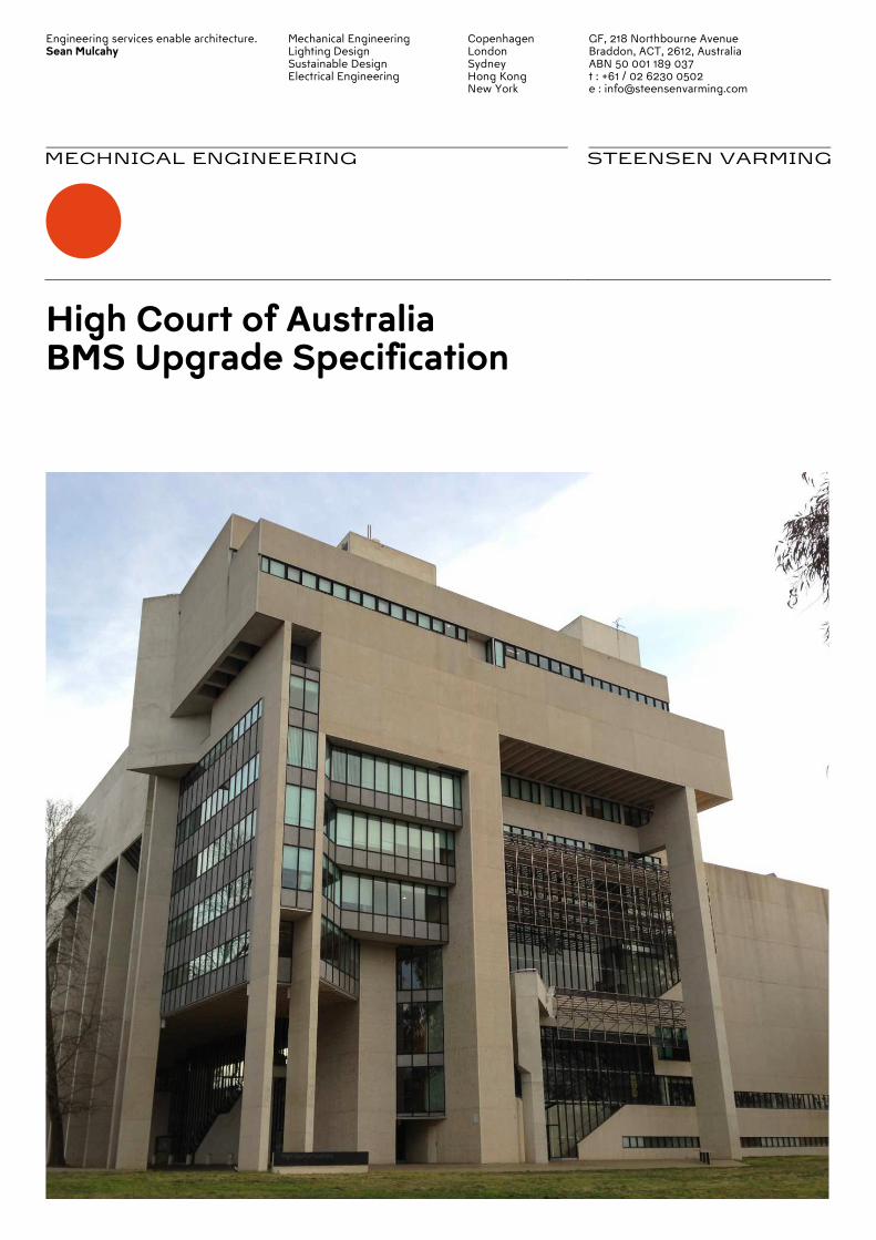
High Court of Australia BMS Upgrade Specification
Engineering services enable architecture. Sean Mulcahy
Mechanical Engineering Lighting Design Sustainable Design Electrical Engineering
Copenhagen London Sydney Hong Kong New York
GF, 218 Northbourne Avenue Braddon, ACT, 2612, Australia ABN 50 001 189 037 t : +61 / 02 6230 0502 e : [email protected]
STEENSEN VARMING
Page 2 / 80 steensenvarming.com
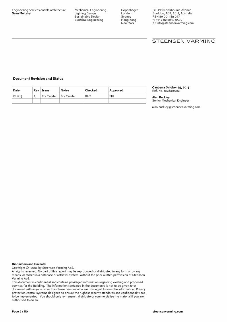
Document Revision and Status
Date Rev Issue Notes Checked Approved
12.11.13 A For Tender For Tender RHT MH
Disclaimers and Caveats: Copyright © 2013, by Steensen Varming ApS. All rights reserved. No part of this report may be reproduced or distributed in any form or by any means, or stored in a database or retrieval system, without the prior written permission of Steensen Varming ApS. This document is confidential and contains privileged information regarding existing and proposed services for the Building. The information contained in the documents is not to be given to or discussed with anyone other than those persons who are privileged to view the information. Privacy protection control systems designed to ensure the highest security standards and confidentiality are to be implemented. You should only re-transmit, distribute or commercialise the material if you are authorised to do so.
Canberra October 25, 2013 Ref. No. 13783sr002 Alan Buckley Senior Mechanical Engineer [email protected]
Engineering services enable architecture. Sean Mulcahy
Mechanical Engineering Lighting Design Sustainable Design Electrical Engineering
Copenhagen London Sydney Hong Kong New York
GF, 218 Northbourne Avenue Braddon, ACT, 2612, Australia ABN 50 001 189 037 t : +61 / 02 6230 0502 e : [email protected]
STEENSEN VARMING
Page 3 / 80 steensenvarming.com
Table of contents 1.0 Part 1 – Project General 5
1.1 Project Description 5
1.2 Definitions 7
1.3 Staging and Continuity of Operations 8
1.4 Related Documents 9
1.5 Redundant Equipment 9
1.6 Heritage Considerations 9
1.7 Building Management System (BMS) Description 10
1.8 Scope of Works 12
1.9 Conformity with Codes and Standards 14
1.10 Visit the Site 15
1.11 Inspection and Testing of Works 15
1.12 Pre-construction Submissions 15
1.13 Completion Activities 17
1.14 Warranties 20
1.15 Ownership of Proprietary Material 20
1.16 Glossary of Terms 21
2.0 Part 2 – Equipment and Performance 22
2.1 General 22
2.2 Communications 22
2.3 Communication Protocols 23
2.4 Operator Interface 24
2.5 Remote Access 32
2.6 Outstation Controllers 33
2.7 Controller Software 35
2.8 Redundancy and Reliability 36
2.9 Future system expansion 37
2.10 Power Supply, UPS and Line Filtering 38
2.11 Power Metering 45
2.12 Field Devices 47
3.0 Part 3 – Execution 50
3.1 General Workmanship and Good Practice 50
3.2 Field Quality Control 51 3.3 Existing Equipment 51 3.4 Communications Cabling 53
3.5 Installation of Temperature Sensors 56
3.6 Warning Labels 57
3.7 Labelling of Hardware and Wiring 57
3.8 Controllers 57
3.9 Programming 58
3.10 Testing and Commissioning 59
3.11 Demonstration and Acceptance 59
3.12 Cleaning 61 3.13 Maintenance 61
4.0 Part 4 –Control Strategies 63
Engineering services enable architecture. Sean Mulcahy
Mechanical Engineering Lighting Design Sustainable Design Electrical Engineering
Copenhagen London Sydney Hong Kong New York
GF, 218 Northbourne Avenue Braddon, ACT, 2612, Australia ABN 50 001 189 037 t : +61 / 02 6230 0502 e : [email protected]
STEENSEN VARMING
Page 4 / 80 steensenvarming.com
4.1 General 63
4.2 Mechanical Services 63
4.3 Vertical Transportation 72
4.4 Electrical Systems 72
4.5 Hydraulic Services 73
4.6 Fire and Life Safety Services 76
4.7 Integration with Security Systems 77
5.0 Appendix A – Control and Monitoring Points List 78
6.0 Appendix B – As-Built Documentation for Information 79
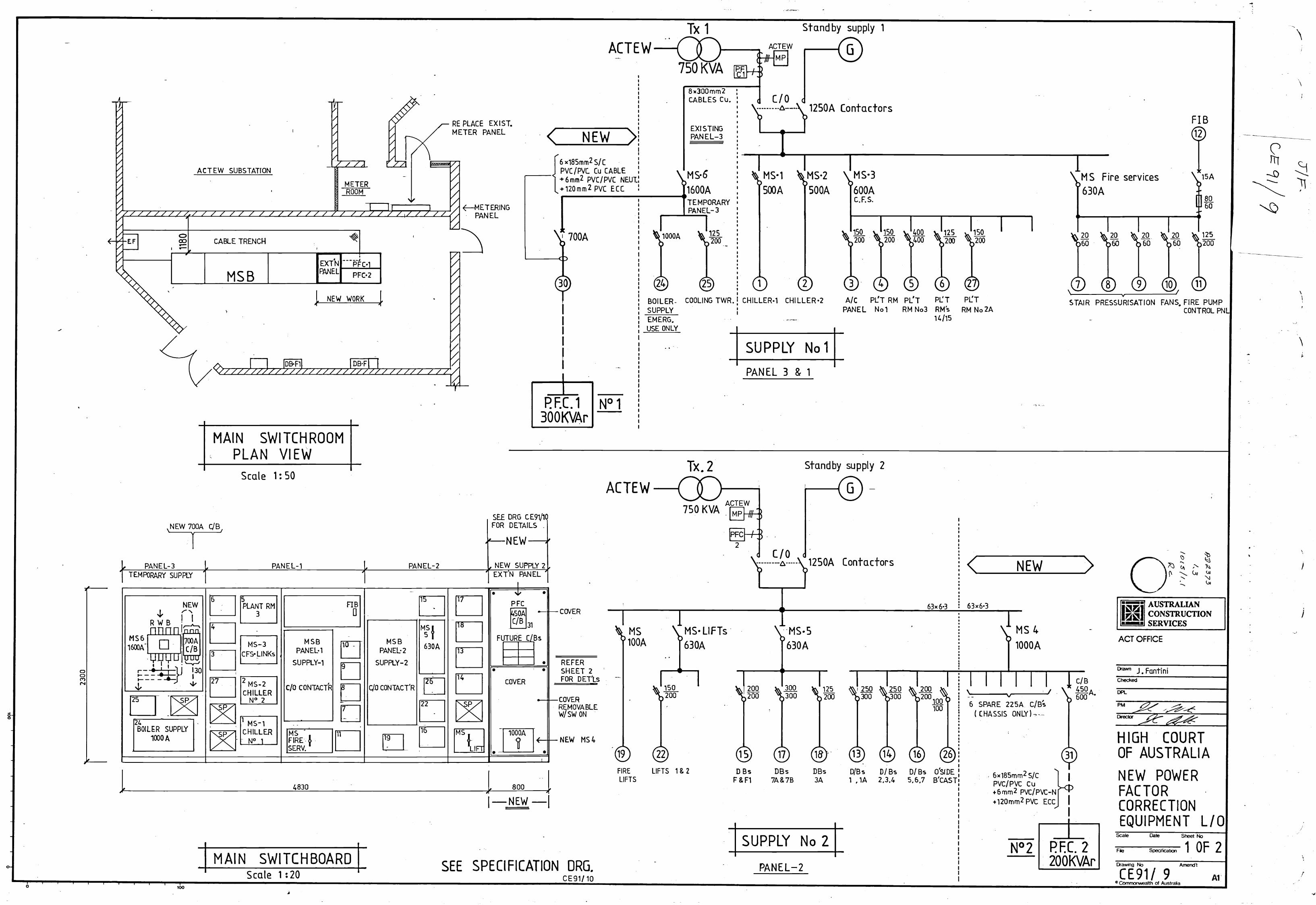
6.1 Electrical Single Line Diagram 79
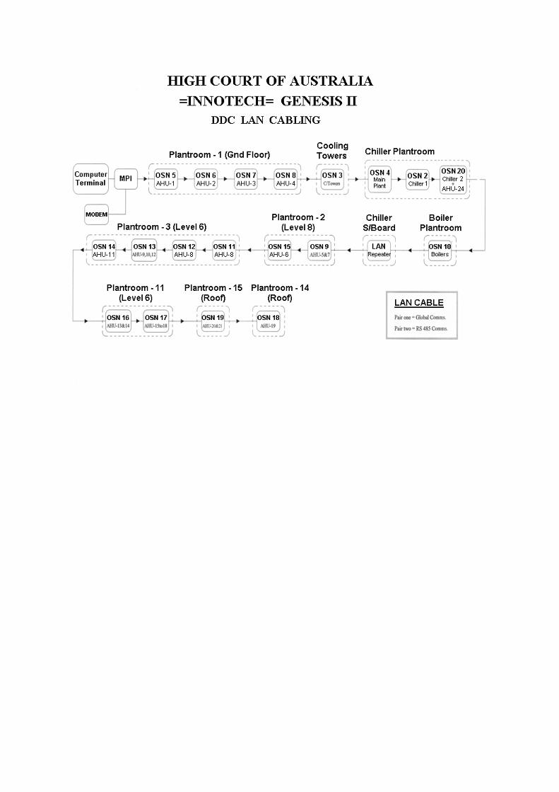
6.2 Existing LAN Cabling Schematic 80
Engineering services enable architecture. Sean Mulcahy
Mechanical Engineering Lighting Design Sustainable Design Electrical Engineering
Copenhagen London Sydney Hong Kong New York
GF, 218 Northbourne Avenue Braddon, ACT, 2612, Australia ABN 50 001 189 037 t : +61 / 02 6230 0502 e : [email protected]
STEENSEN VARMING
Page 5 / 80 steensenvarming.com
1.0 Part 1 – Project General
1.1 Project Description
The High Court Building is one of Australia’s national buildings and is located on the shores of Lake Burley Griffin in Canberra’s Parliamentary Triangle. Design of the building began in 1973 with construction starting on site in 1975; the completed building was first occupied in June 1980. The main functional elements of the building are a large public hall, three courtrooms, an administrative wing and Justices chambers. The original heating ventilation and air condition (HVAC) control system comprised of pneumatic controls which were replaced in 1999 with a proprietary Innotech electronic direct digitial control (DDC) based system. With DDC / BMS systems generally having an operational and servicable lifespan of 10-15 years, the existing system is due for an upgrade to provide more control, monitoring and measurement functionality over systems and building energy consumption. In addition to this, a key objective of the project is to future proof the facilities’ control system to integrate with current, future and emerging technologies that may be put in place as a part of planned plant and system upgrades. The upgrade involves the installation of a new BMS server / central station, head-end PC, communication network and outstation controllers. The majority of field devices (with the exception of temperature sensors) will be retained where they are in good working order and compatible, taking into consideration that the existing heating ventilation and air conditioning (HVAC) systems will be renewed in the short term following the BMS upgrade. The following is a description of the key objectives for the project: � Energy Efficiency – a system which has the ability to carry out sophisticated and
energy efficienty control strategies as well as energy managements systems for Building Managers to track and interrogate the performance of individual systems with the view of reducing the building energy consumption and associated greenhouse gas emissions. It should be noted that the potential control strategies are limited to the ability of the existing system infrastructure. As the High Court HVAC systems are due an upgrade – only when these systems are replaced can the High Court realise the full energy efficiency capabilities through automated control.
� User-friendly Operability and Monitoring – a system which provides Building
Managers, even with limited expertise and training to carry out the simplist of tasks or general system monitoring and interrogation.
� Alarms and fault detection – a system which provides Facilities Management
with a fault detection systems with appropriate prioritisation, communication, acknowledgement and action systems.
Engineering services enable architecture. Sean Mulcahy
Mechanical Engineering Lighting Design Sustainable Design Electrical Engineering
Copenhagen London Sydney Hong Kong New York
GF, 218 Northbourne Avenue Braddon, ACT, 2612, Australia ABN 50 001 189 037 t : +61 / 02 6230 0502 e : [email protected]
STEENSEN VARMING
Page 6 / 80 steensenvarming.com
� Cost Effectiveness - A value for money approach over the total life of the project. The capital cost, operational costs, maintenance and support costs are all to be considered in the tender submission including the adaptive re-use of the existing BMS infrastructure. Including fixed schedule of rates for additional points in the future.
� Integration – expansion of the monitoring and control of the wider building
services systems current manually controlled such as future lighting control, back-up generators, hydraulic systems (water supply and water features) and electrical systems. The new system will look to interface with the following current and future systems: - Building HVAC systems - Back-up power systems - General power systems (metering, power management) - Future lighting controls - Vertical transportation systems - Hydraulic systems (water feature, mains water, gas supply, domestic hot
water) � Reports – a system with the capability to automatically generate monthly
reports of key trends, logs and alarms. � Local support – a system which is installed and commissioned by a Vendor
which has the ability to provide 24-hour local support and periodic performance maintenance for the life of the system software and hardware. As a part of the specification and contract, the new system provider will be required to submit the option price to undertake comprehensive maintenance for a period of 5 years.
� Future flexibility – a system which future proofs the High Courts needs for both
anticipated and unanticipated upgrades. The system will be specified in support of open communication protocols to interface a wide variety of building services systems and equipment. In addition to this, software upgrades and data migration / back-up will be specified as forming part of the 5-year maintenance contract.
� Security – a system which is protected from vulnerabilities and access by
unwanted personnel which may cause disruption to the facilities operation. Remote access will be provided through a secure and password protected network for authorised personnel.
� Staging and Continuity of Operations – an installation approach which creates
minimum disruption to the High Court operations. Intrusive works will be specified as to be undertaken outside of key court-sitting dates. Works resulting in down-time to systems will be specified as to be undertaken outside of occupied hours. Consideration will be given to heritage implications where access is required within ceiling and walls for installation of new cabling.
� Redundancy and Reliability – a system which is adequately protected from
power fluctuations and outages and provides secure back-up for operating programs and trend data through surge protection, power filtration and UPS back-up for the central server and distributed outstations.
Engineering services enable architecture. Sean Mulcahy
Mechanical Engineering Lighting Design Sustainable Design Electrical Engineering
Copenhagen London Sydney Hong Kong New York
GF, 218 Northbourne Avenue Braddon, ACT, 2612, Australia ABN 50 001 189 037 t : +61 / 02 6230 0502 e : [email protected]
STEENSEN VARMING
Page 7 / 80 steensenvarming.com
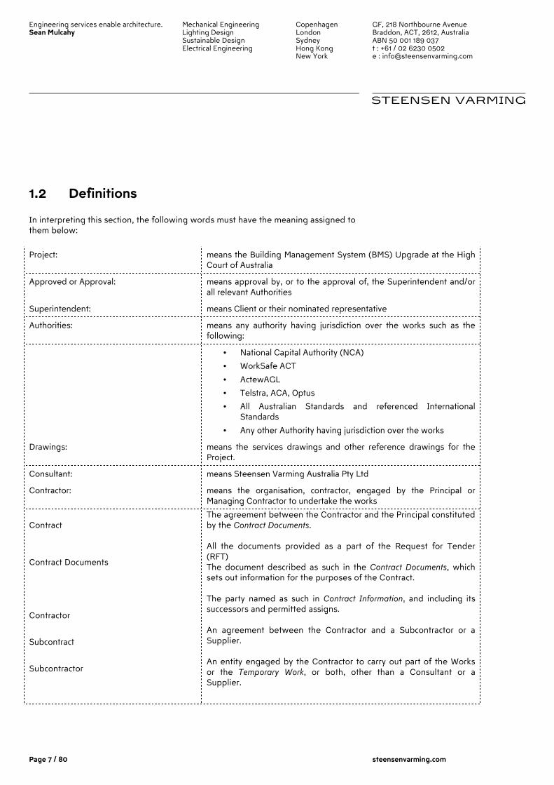
1.2 Definitions
In interpreting this section, the following words must have the meaning assigned to them below:
Project: means the Building Management System (BMS) Upgrade at the High Court of Australia
Approved or Approval: means approval by, or to the approval of, the Superintendent and/or all relevant Authorities
Superintendent: means Client or their nominated representative
Authorities: means any authority having jurisdiction over the works such as the following:
• National Capital Authority (NCA)
• WorkSafe ACT
• ActewAGL
• Telstra, ACA, Optus
• All Australian Standards and referenced International Standards
• Any other Authority having jurisdiction over the works
Drawings: means the services drawings and other reference drawings for the Project.
Consultant: means Steensen Varming Australia Pty Ltd
Contractor: means the organisation, contractor, engaged by the Principal or Managing Contractor to undertake the works
Contract
Contract Documents
Contractor
Subcontract
Subcontractor
The agreement between the Contractor and the Principal constituted by the Contract Documents. All the documents provided as a part of the Request for Tender (RFT) The document described as such in the Contract Documents, which sets out information for the purposes of the Contract. The party named as such in Contract Information, and including its successors and permitted assigns. An agreement between the Contractor and a Subcontractor or a Supplier. An entity engaged by the Contractor to carry out part of the Works or the Temporary Work, or both, other than a Consultant or a Supplier.
Engineering services enable architecture. Sean Mulcahy
Mechanical Engineering Lighting Design Sustainable Design Electrical Engineering
Copenhagen London Sydney Hong Kong New York
GF, 218 Northbourne Avenue Braddon, ACT, 2612, Australia ABN 50 001 189 037 t : +61 / 02 6230 0502 e : [email protected]
STEENSEN VARMING
Page 8 / 80 steensenvarming.com
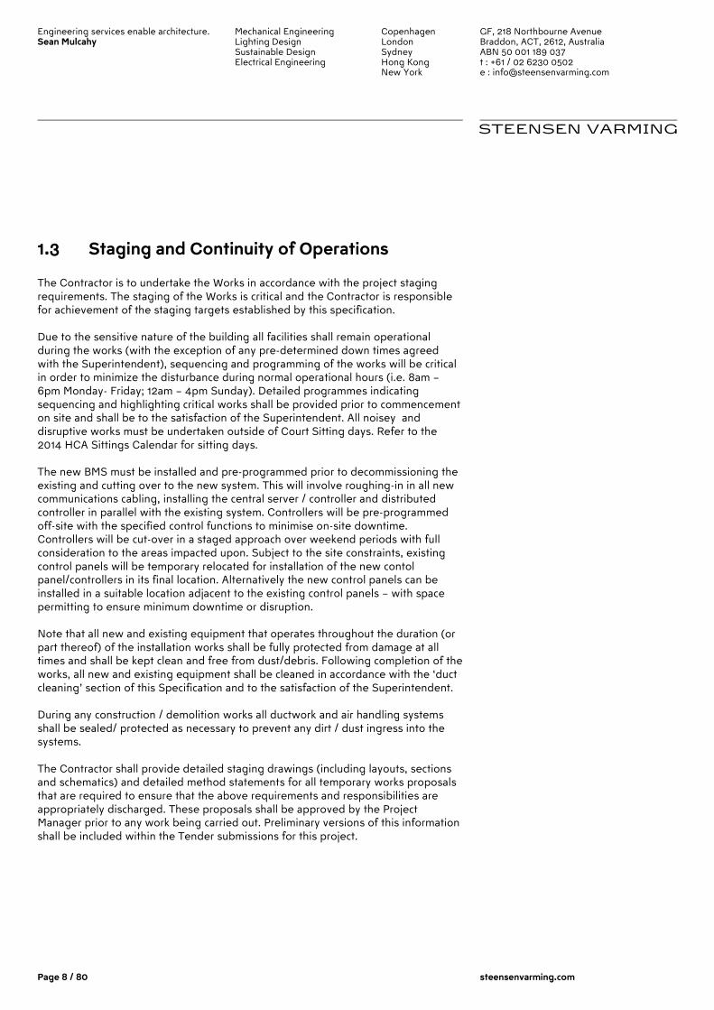
1.3 Staging and Continuity of Operations
The Contractor is to undertake the Works in accordance with the project staging requirements. The staging of the Works is critical and the Contractor is responsible for achievement of the staging targets established by this specification. Due to the sensitive nature of the building all facilities shall remain operational during the works (with the exception of any pre-determined down times agreed with the Superintendent), sequencing and programming of the works will be critical in order to minimize the disturbance during normal operational hours (i.e. 8am – 6pm Monday- Friday; 12am – 4pm Sunday). Detailed programmes indicating sequencing and highlighting critical works shall be provided prior to commencement on site and shall be to the satisfaction of the Superintendent. All noisey and disruptive works must be undertaken outside of Court Sitting days. Refer to the 2014 HCA Sittings Calendar for sitting days. The new BMS must be installed and pre-programmed prior to decommissioning the existing and cutting over to the new system. This will involve roughing-in in all new communications cabling, installing the central server / controller and distributed controller in parallel with the existing system. Controllers will be pre-programmed off-site with the specified control functions to minimise on-site downtime. Controllers will be cut-over in a staged approach over weekend periods with full consideration to the areas impacted upon. Subject to the site constraints, existing control panels will be temporary relocated for installation of the new contol panel/controllers in its final location. Alternatively the new control panels can be installed in a suitable location adjacent to the existing control panels – with space permitting to ensure minimum downtime or disruption. Note that all new and existing equipment that operates throughout the duration (or part thereof) of the installation works shall be fully protected from damage at all times and shall be kept clean and free from dust/debris. Following completion of the works, all new and existing equipment shall be cleaned in accordance with the ‘duct cleaning’ section of this Specification and to the satisfaction of the Superintendent. During any construction / demolition works all ductwork and air handling systems shall be sealed/ protected as necessary to prevent any dirt / dust ingress into the systems. The Contractor shall provide detailed staging drawings (including layouts, sections and schematics) and detailed method statements for all temporary works proposals that are required to ensure that the above requirements and responsibilities are appropriately discharged. These proposals shall be approved by the Project Manager prior to any work being carried out. Preliminary versions of this information shall be included within the Tender submissions for this project.
Engineering services enable architecture. Sean Mulcahy
Mechanical Engineering Lighting Design Sustainable Design Electrical Engineering
Copenhagen London Sydney Hong Kong New York
GF, 218 Northbourne Avenue Braddon, ACT, 2612, Australia ABN 50 001 189 037 t : +61 / 02 6230 0502 e : [email protected]
STEENSEN VARMING
Page 9 / 80 steensenvarming.com
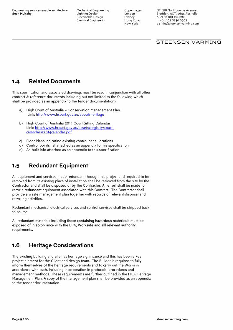
1.4 Related Documents
This specification and associated drawings must be read in conjunction with all other contract & reference documents including but not limited to the following which shall be provided as an appendix to the tender documentation:-
a) High Court of Australia – Conservation Management Plan. Link: http://www.hcourt.gov.au/about/heritage
b) High Court of Australia 2014 Court Sitting Calendar Link: http://www.hcourt.gov.au/assets/registry/court-calendars/2014calendar.pdf
c) Floor Plans indicating existing control panel locations d) Control points list attached as an appendix to this specification e) As-built info attached as an appendix to this specification
1.5 Redundant Equipment
All equipment and services made redundant through this project and required to be removed from its existing place of installation shall be removed from the site by the Contractor and shall be disposed of by the Contractor. All effort shall be made to recycle redundant equipment associated with this Contract. The Contractor shall provide a waste management plan together with records of relevant disposal and recycling activities. Redundant mechanical electrical services and control services shall be stripped back to source. All redundant materials including those containing hazardous matericals must be exposed of in accordance with the EPA, Worksafe and alll relevant authority requirments.
1.6 Heritage Considerations
The existing building and site has heritage significance and this has been a key project element for the Client and design team. The Builder is required to fully inform themselves of the heritage requirements and to carry out the Works in accordance with such, including incorporation in protocols, procedures and management methods. These requirements are further outlined in the HCA Heritage Management Plan. A copy of the management plan shall be provided as an appendix to the tender documentation.
Engineering services enable architecture. Sean Mulcahy
Mechanical Engineering Lighting Design Sustainable Design Electrical Engineering
Copenhagen London Sydney Hong Kong New York
GF, 218 Northbourne Avenue Braddon, ACT, 2612, Australia ABN 50 001 189 037 t : +61 / 02 6230 0502 e : [email protected]
STEENSEN VARMING
Page 10 / 80 steensenvarming.com
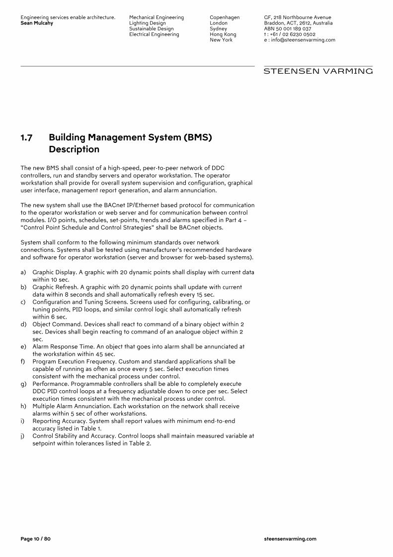
1.7 Building Management System (BMS) Description
The new BMS shall consist of a high-speed, peer-to-peer network of DDC controllers, run and standby servers and operator workstation. The operator workstation shall provide for overall system supervision and configuration, graphical user interface, management report generation, and alarm annunciation. The new system shall use the BACnet IP/Ethernet based protocol for communication to the operator workstation or web server and for communication between control modules. I/O points, schedules, set-points, trends and alarms specified in Part 4 – “Control Point Schedule and Control Strategies” shall be BACnet objects. System shall conform to the following minimum standards over network connections. Systems shall be tested using manufacturer’s recommended hardware and software for operator workstation (server and browser for web-based systems). a) Graphic Display. A graphic with 20 dynamic points shall display with current data
within 10 sec. b) Graphic Refresh. A graphic with 20 dynamic points shall update with current
data within 8 seconds and shall automatically refresh every 15 sec. c) Configuration and Tuning Screens. Screens used for configuring, calibrating, or
tuning points, PID loops, and similar control logic shall automatically refresh within 6 sec.
d) Object Command. Devices shall react to command of a binary object within 2 sec. Devices shall begin reacting to command of an analogue object within 2 sec.
e) Alarm Response Time. An object that goes into alarm shall be annunciated at the workstation within 45 sec.
f) Program Execution Frequency. Custom and standard applications shall be capable of running as often as once every 5 sec. Select execution times consistent with the mechanical process under control.
g) Performance. Programmable controllers shall be able to completely execute DDC PID control loops at a frequency adjustable down to once per sec. Select execution times consistent with the mechanical process under control.
h) Multiple Alarm Annunciation. Each workstation on the network shall receive alarms within 5 sec of other workstations.
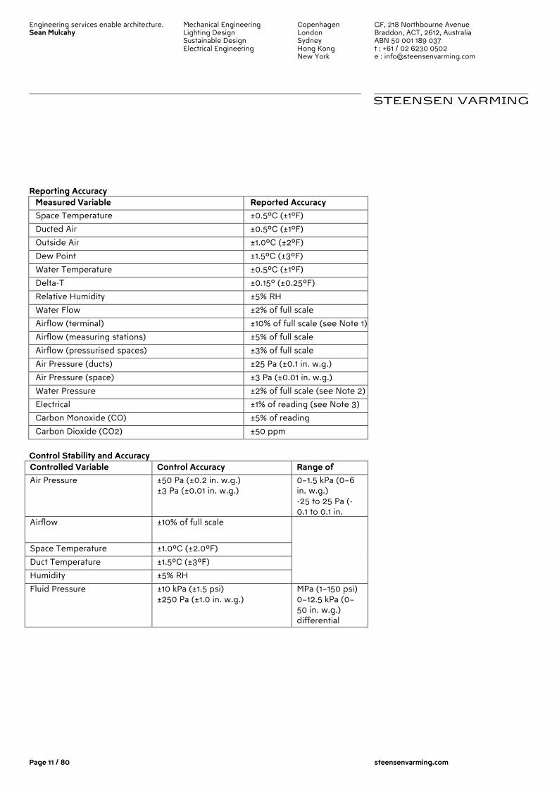
i) Reporting Accuracy. System shall report values with minimum end-to-end accuracy listed in Table 1.
j) Control Stability and Accuracy. Control loops shall maintain measured variable at setpoint within tolerances listed in Table 2.
Engineering services enable architecture. Sean Mulcahy
Mechanical Engineering Lighting Design Sustainable Design Electrical Engineering
Copenhagen London Sydney Hong Kong New York
GF, 218 Northbourne Avenue Braddon, ACT, 2612, Australia ABN 50 001 189 037 t : +61 / 02 6230 0502 e : [email protected]
STEENSEN VARMING
Page 11 / 80 steensenvarming.com
Reporting Accuracy
Measured Variable Reported Accuracy
Space Temperature ±0.5ºC (±1ºF)
Ducted Air ±0.5ºC (±1ºF)
Outside Air ±1.0ºC (±2ºF)
Dew Point ±1.5ºC (±3ºF)
Water Temperature ±0.5ºC (±1ºF)
Delta-T ±0.15º (±0.25ºF)
Relative Humidity ±5% RH
Water Flow ±2% of full scale
Airflow (terminal) ±10% of full scale (see Note 1)
Airflow (measuring stations) ±5% of full scale
Airflow (pressurised spaces) ±3% of full scale
Air Pressure (ducts) ±25 Pa (±0.1 in. w.g.)
Air Pressure (space) ±3 Pa (±0.01 in. w.g.)
Water Pressure ±2% of full scale (see Note 2)
Electrical ±1% of reading (see Note 3)
Carbon Monoxide (CO) ±5% of reading
Carbon Dioxide (CO2) ±50 ppm
Control Stability and Accuracy
Controlled Variable Control Accuracy Range of Medium Air Pressure ±50 Pa (±0.2 in. w.g.)
±3 Pa (±0.01 in. w.g.) 0–1.5 kPa (0–6 in. w.g.) -25 to 25 Pa (-0.1 to 0.1 in.
Airflow ±10% of full scale
Space Temperature ±1.0ºC (±2.0ºF)
Duct Temperature ±1.5ºC (±3ºF)
Humidity ±5% RH
Fluid Pressure ±10 kPa (±1.5 psi) ±250 Pa (±1.0 in. w.g.)
MPa (1–150 psi) 0–12.5 kPa (0–50 in. w.g.) differential
Engineering services enable architecture. Sean Mulcahy
Mechanical Engineering Lighting Design Sustainable Design Electrical Engineering
Copenhagen London Sydney Hong Kong New York
GF, 218 Northbourne Avenue Braddon, ACT, 2612, Australia ABN 50 001 189 037 t : +61 / 02 6230 0502 e : [email protected]
STEENSEN VARMING
Page 12 / 80 steensenvarming.com
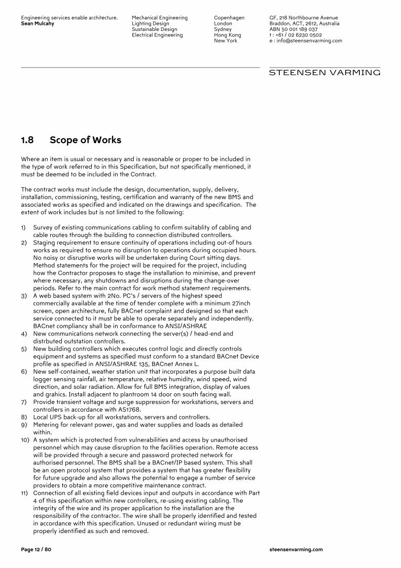
1.8 Scope of Works
Where an item is usual or necessary and is reasonable or proper to be included in the type of work referred to in this Specification, but not specifically mentioned, it must be deemed to be included in the Contract. The contract works must include the design, documentation, supply, delivery, installation, commissioning, testing, certification and warranty of the new BMS and associated works as specified and indicated on the drawings and specification. The extent of work includes but is not limited to the following: 1) Survey of existing communications cabling to confirm suitablity of cabling and
cable routes through the building to connection distributed controllers. 2) Staging requirement to ensure continuity of operations including out-of hours
works as required to ensure no disruption to operations during occupied hours. No noisy or disruptive works will be undertaken during Court sitting days. Method statements for the project will be required for the project, including how the Contractor proposes to stage the installation to minimise, and prevent where necessary, any shutdowns and disruptions during the change-over periods. Refer to the main contract for work method statement requirements.
3) A web based system with 2No. PC’s / servers of the highest speed commercially available at the time of tender complete with a minimum 27inch screen, open architecture, fully BACnet complaint and designed so that each service connected to it must be able to operate separately and independently. BACnet compliancy shall be in conformance to ANSI/ASHRAE
4) New communications network connecting the server(s) / head-end and distrbuted outstation controllers.
5) New building controllers which executes control logic and directly controls equipment and systems as specified must conform to a standard BACnet Device profile as specified in ANSI/ASHRAE 135, BACnet Annex L.
6) New self-contained, weather station unit that incorporates a purpose built data logger sensing rainfall, air temperature, relative humidity, wind speed, wind direction, and solar radiation. Allow for full BMS integration, display of values and grahics. Install adjacent to plantroom 14 door on south facing wall.
7) Provide transient voltage and surge suppression for workstations, servers and controllers in accordance with AS1768.
8) Local UPS back-up for all workstations, servers and controllers. 9) Metering for relevant power, gas and water supplies and loads as detailed
within. 10) A system which is protected from vulnerabilities and access by unauthorised
personnel which may cause disruption to the facilities operation. Remote access will be provided through a secure and password protected network for authorised personnel. The BMS shall be a BACnet/IP based system. This shall be an open protocol system that provides a system that has greater flexibility for future upgrade and also allows the potential to engage a number of service providers to obtain a more competitive maintenance contract.
11) Connection of all existing field devices input and outputs in accordance with Part 4 of this specification within new controllers, re-using existing cabling. The integrity of the wire and its proper application to the installation are the responsibility of the contractor. The wire shall be properly identified and tested in accordance with this specification. Unused or redundant wiring must be properly identified as such and removed.
Engineering services enable architecture. Sean Mulcahy
Mechanical Engineering Lighting Design Sustainable Design Electrical Engineering
Copenhagen London Sydney Hong Kong New York
GF, 218 Northbourne Avenue Braddon, ACT, 2612, Australia ABN 50 001 189 037 t : +61 / 02 6230 0502 e : [email protected]
STEENSEN VARMING
Page 13 / 80 steensenvarming.com
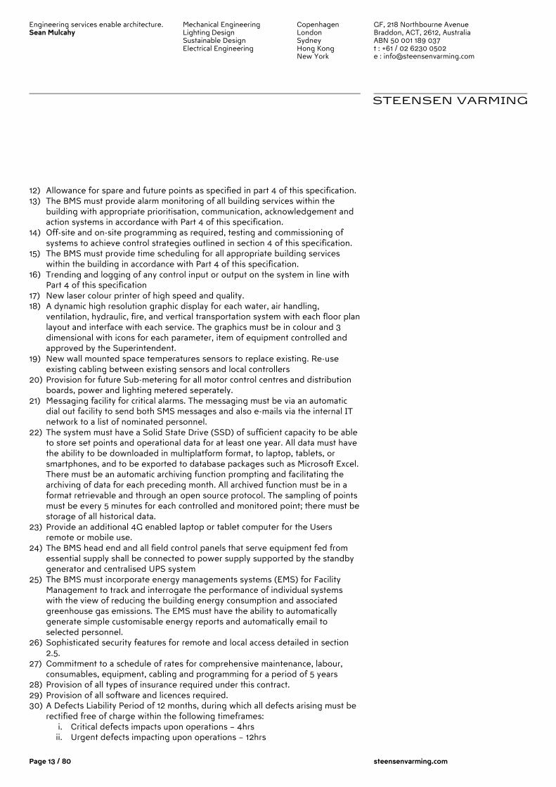
12) Allowance for spare and future points as specified in part 4 of this specification. 13) The BMS must provide alarm monitoring of all building services within the
building with appropriate prioritisation, communication, acknowledgement and action systems in accordance with Part 4 of this specification.
14) Off-site and on-site programming as required, testing and commissioning of systems to achieve control strategies outlined in section 4 of this specification.
15) The BMS must provide time scheduling for all appropriate building services within the building in accordance with Part 4 of this specification.
16) Trending and logging of any control input or output on the system in line with Part 4 of this specification
17) New laser colour printer of high speed and quality. 18) A dynamic high resolution graphic display for each water, air handling,
ventilation, hydraulic, fire, and vertical transportation system with each floor plan layout and interface with each service. The graphics must be in colour and 3 dimensional with icons for each parameter, item of equipment controlled and approved by the Superintendent.
19) New wall mounted space temperatures sensors to replace existing. Re-use existing cabling between existing sensors and local controllers
20) Provision for future Sub-metering for all motor control centres and distribution boards, power and lighting metered seperately.
21) Messaging facility for critical alarms. The messaging must be via an automatic dial out facility to send both SMS messages and also e-mails via the internal IT network to a list of nominated personnel.
22) The system must have a Solid State Drive (SSD) of sufficient capacity to be able to store set points and operational data for at least one year. All data must have the ability to be downloaded in multiplatform format, to laptop, tablets, or smartphones, and to be exported to database packages such as Microsoft Excel. There must be an automatic archiving function prompting and facilitating the archiving of data for each preceding month. All archived function must be in a format retrievable and through an open source protocol. The sampling of points must be every 5 minutes for each controlled and monitored point; there must be storage of all historical data.
23) Provide an additional 4G enabled laptop or tablet computer for the Users remote or mobile use.
24) The BMS head end and all field control panels that serve equipment fed from essential supply shall be connected to power supply supported by the standby generator and centralised UPS system
25) The BMS must incorporate energy managements systems (EMS) for Facility Management to track and interrogate the performance of individual systems with the view of reducing the building energy consumption and associated greenhouse gas emissions. The EMS must have the ability to automatically generate simple customisable energy reports and automatically email to selected personnel.
26) Sophisticated security features for remote and local access detailed in section 2.5.
27) Commitment to a schedule of rates for comprehensive maintenance, labour, consumables, equipment, cabling and programming for a period of 5 years
28) Provision of all types of insurance required under this contract. 29) Provision of all software and licences required. 30) A Defects Liability Period of 12 months, during which all defects arising must be
rectified free of charge within the following timeframes: i. Critical defects impacts upon operations – 4hrs ii. Urgent defects impacting upon operations – 12hrs

Engineering services enable architecture. Sean Mulcahy
Mechanical Engineering Lighting Design Sustainable Design Electrical Engineering
Copenhagen London Sydney Hong Kong New York
GF, 218 Northbourne Avenue Braddon, ACT, 2612, Australia ABN 50 001 189 037 t : +61 / 02 6230 0502 e : [email protected]
STEENSEN VARMING
Page 14 / 80 steensenvarming.com
iii. Important defects non impacting upon operations – 5 days iv. Non-critical defects – 14 days
31) Comprehensive maintenance contract for a period of 5 years 32) Workshop Drawings, and ‘as installed’ drawings. Full operating and
maintenance instruction manuals prior to Completion. 33) A system which is installed and commissioned by a Vendor which has the ability
to provide 24-hour local support in the ACT region and periodic performance maintenance for a period of 5 years.
34) Comprehensive training of HCA Factilities Management staff. 35) Instruction of the building’s personnel who will be in charge of operation of the
plant after commissioning with regard to preventative maintenance procedures. 36) Make adequate allowances in programming for the following:
i. Detailed investigation and site surveys of the current installation and equipment
ii. System submission for consultants review iii. Staging requirements to keep the system operational iv. Equipment submission for consultants review v. Working drawing submission for consultants review vi. Completion and rectification of defects vii. Programming of all control logics, report templates and alarm
scheduling etc viii. Testing and commissioning, final testing and witnessing by the
Superintendent and their representative ix. The Superintendent and (or their representative) will require 10
working days to check any submissions
1.9 Conformity with Codes and Standards
Work, materials, and equipment shall comply with the most restrictive of local, state, and federal authorities' codes and ordinances or these plans and specifications. As a minimum, the installation shall comply with the current editions in effect 30 days prior to the receipt of bids of the following codes:
� ANSI/ASHRAE Standard 135, BACnet - A Data Communication � Electrical work: To AS/NZS 3000 Australia/New Zealand Wiring Rules. � Fire and smoke control: To AS 1668:1, Fire and smoke control in
multicompartment buildings. � AS/NZS1367 :Coaxial cable and optical fibre systems for the RF distribution
of analog and digital television and sound signals in single and multiple dwelling installations
� Australian Communications Media Authority (ACMA) Installation Requirement for Customer Wiring AS3080, AS3084, AS/NZS 3085, AS/NZS 3087
� AS/ACIF S008 and AS/ACIF S009
Engineering services enable architecture. Sean Mulcahy
Mechanical Engineering Lighting Design Sustainable Design Electrical Engineering
Copenhagen London Sydney Hong Kong New York
GF, 218 Northbourne Avenue Braddon, ACT, 2612, Australia ABN 50 001 189 037 t : +61 / 02 6230 0502 e : [email protected]
STEENSEN VARMING
Page 15 / 80 steensenvarming.com
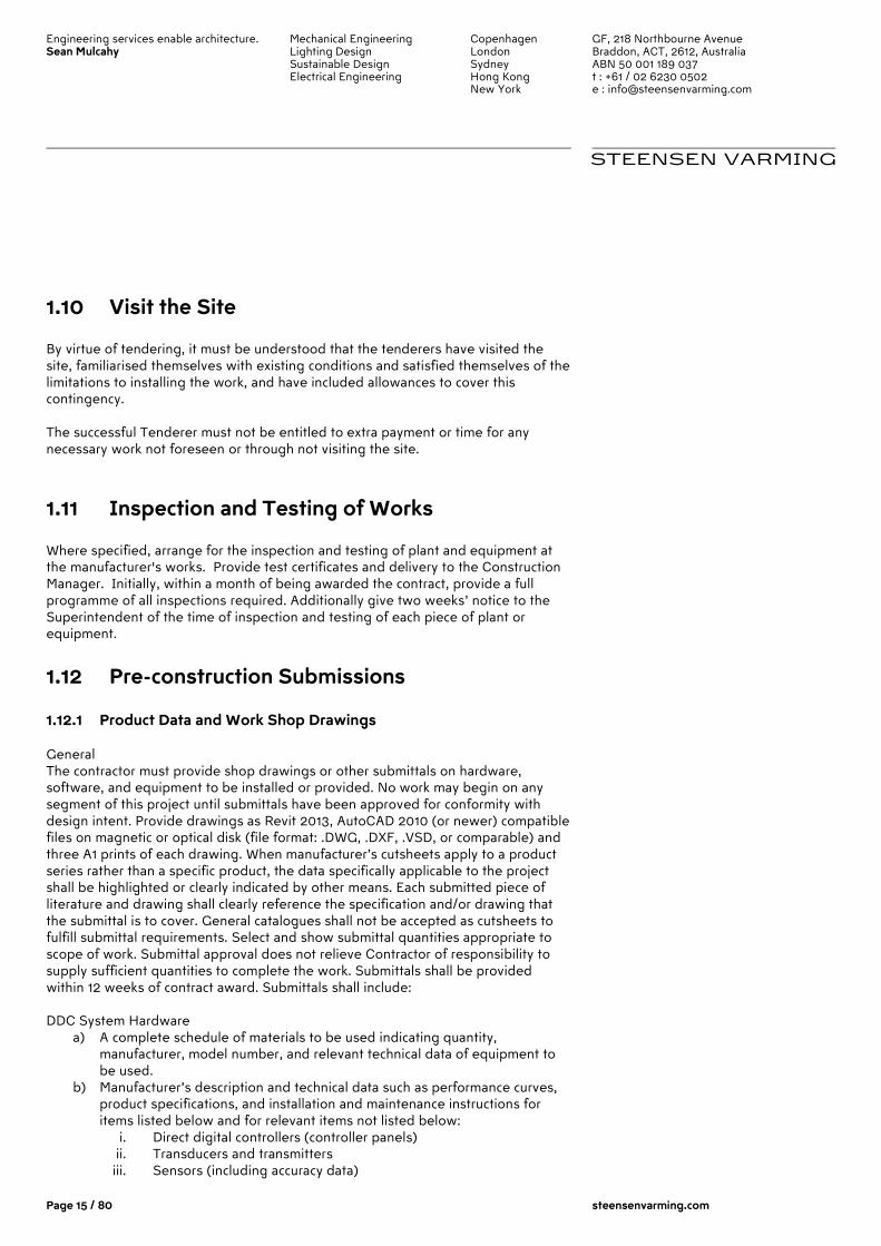
1.10 Visit the Site
By virtue of tendering, it must be understood that the tenderers have visited the site, familiarised themselves with existing conditions and satisfied themselves of the limitations to installing the work, and have included allowances to cover this contingency. The successful Tenderer must not be entitled to extra payment or time for any necessary work not foreseen or through not visiting the site.
1.11 Inspection and Testing of Works
Where specified, arrange for the inspection and testing of plant and equipment at the manufacturer's works. Provide test certificates and delivery to the Construction Manager. Initially, within a month of being awarded the contract, provide a full programme of all inspections required. Additionally give two weeks’ notice to the Superintendent of the time of inspection and testing of each piece of plant or equipment.
1.12 Pre-construction Submissions
1.12.1 Product Data and Work Shop Drawings General The contractor must provide shop drawings or other submittals on hardware, software, and equipment to be installed or provided. No work may begin on any segment of this project until submittals have been approved for conformity with design intent. Provide drawings as Revit 2013, AutoCAD 2010 (or newer) compatible files on magnetic or optical disk (file format: .DWG, .DXF, .VSD, or comparable) and three A1 prints of each drawing. When manufacturer’s cutsheets apply to a product series rather than a specific product, the data specifically applicable to the project shall be highlighted or clearly indicated by other means. Each submitted piece of literature and drawing shall clearly reference the specification and/or drawing that the submittal is to cover. General catalogues shall not be accepted as cutsheets to fulfill submittal requirements. Select and show submittal quantities appropriate to scope of work. Submittal approval does not relieve Contractor of responsibility to supply sufficient quantities to complete the work. Submittals shall be provided within 12 weeks of contract award. Submittals shall include: DDC System Hardware
a) A complete schedule of materials to be used indicating quantity, manufacturer, model number, and relevant technical data of equipment to be used.
b) Manufacturer’s description and technical data such as performance curves, product specifications, and installation and maintenance instructions for items listed below and for relevant items not listed below:
i. Direct digital controllers (controller panels) ii. Transducers and transmitters iii. Sensors (including accuracy data)

Engineering services enable architecture. Sean Mulcahy
Mechanical Engineering Lighting Design Sustainable Design Electrical Engineering
Copenhagen London Sydney Hong Kong New York
GF, 218 Northbourne Avenue Braddon, ACT, 2612, Australia ABN 50 001 189 037 t : +61 / 02 6230 0502 e : [email protected]
STEENSEN VARMING
Page 16 / 80 steensenvarming.com
iv. Actuators v. Valves vi. Relays and switches vii. Control panels viii. Power supplies ix. UPS x. Batteries xi. Operator interface equipment xii. Wiring
c) Wiring diagrams and layouts for each control panel. Show termination numbers.
d) Schematic diagrams for all field sensors and controllers. Provide floor plans of all sensor locations and control hardware. Riser diagrams showing control network layout, communication protocol, and wire types.
Central System Hardware and Software a) A complete schedule of material of equipment used indicating quantity,
manufacturer, model number, and relevant technical. b) Manufacturer’s description and technical data such as product specifications
and installation and maintenance instructions for items listed below and for relevant items furnished under this contract not listed below:
i. Central Processing Unit (CPU) or web server ii. Monitors iii. Keyboards iv. Printers v. Power supplies vi. Battery backups vii. Interface equipment between CPU or server and control panels viii. Operating System software ix. Operator interface software x. Colour graphic software xi. Third-party software
c) Schematic diagrams for all control, communication, and power wiring. Provide a schematic drawing of the central system installation. Label all cables and ports with computer manufacturers’ model numbers and functions. Show interface wiring to control system.
d) Network riser diagrams of wiring between central control unit and control panels.
Controlled Systems a) Riser diagrams showing control network layout, communication protocol,
and wire types. b) A schematic diagram of each controlled system. The schematics shall have
all control points labelled with point names shown or listed. The schematics shall graphically show the location of all control elements in the system.
c) A schematic wiring diagram of each controlled system. Label control elements and terminals. Where a control element is also shown on control system schematic, use the same name.
d) An instrumentation list (Bill of Materials) for each controlled system. List each control system element in a table. Show element name, type of device, manufacturer, model number, and product data sheet number.
e) A mounting, wiring, and routing plan-view drawing. The design shall take into account HVAC, electrical and other systems’ design and elevation
Engineering services enable architecture. Sean Mulcahy
Mechanical Engineering Lighting Design Sustainable Design Electrical Engineering
Copenhagen London Sydney Hong Kong New York
GF, 218 Northbourne Avenue Braddon, ACT, 2612, Australia ABN 50 001 189 037 t : +61 / 02 6230 0502 e : [email protected]
STEENSEN VARMING
Page 17 / 80 steensenvarming.com
requirements. The drawing shall show the specific location of all concrete pads and bases and any special wall bracing for panels to accommodate this work.
f) A complete description of the operation of the control system, including sequences of operation. The description shall include and reference a schematic diagram of the controlled system.
g) A point list for each control system. List I/O points and software points specified in Section 4. Indicate alarmed and trended points.
Quantities of items submitted shall be reviewed but are the responsibility of the Contractor. Provide a description of process, report formats, and checklists to be used. Provide BACnet Protocol Implementation Conformance Statement (PICS) for each submitted type of controller and operator interface.
1.12.2 Schedules Within one month of contract award, provide a schedule of the work indicating the following:
a) Intended sequence of work items b) Start date of each work item c) Duration of each work item d) A schedule of works for approval by the Superintendent e) Planned delivery dates for ordered material and equipment and expected
lead times f) Milestones indicating possible restraints on work by other trades or
situations Monthly written status reports indicating work completed and revisions to expected delivery dates. Include updated schedule of work.
1.13 Completion Activities
1.13.1 Project Record Documents Upon completion of installation, submit three hard copies and electronic copy of record (as-built) documents of the documents shall be submitted for approval prior to final completion and shall include:
a) Project Record Drawings. As-built versions of submittal shop drawings provided as Revit MEP 2013, AutoCAD 2010 (or newer) compatible files on magnetic or optical media (file format: .DWG, .DXF, .VSD, or comparable) and as A3 prints.
b) Testing and Commissioning Reports and Checklists. Completed versions of reports, checklists, and trend logs used to meet requirements of this specification.
c) Operation and Maintenance (O&M) Manual. d) As-built versions of submittal product data. e) Names, addresses, and telephone numbers of installing contractors and
service representatives for equipment and control systems.
Engineering services enable architecture. Sean Mulcahy
Mechanical Engineering Lighting Design Sustainable Design Electrical Engineering
Copenhagen London Sydney Hong Kong New York
GF, 218 Northbourne Avenue Braddon, ACT, 2612, Australia ABN 50 001 189 037 t : +61 / 02 6230 0502 e : [email protected]
STEENSEN VARMING
Page 18 / 80 steensenvarming.com
f) Operator’s manual with procedures for operating control systems: logging on and off, handling alarms, producing point reports, trending data, overriding computer control, and changing setpoints and variables.
g) Programming manual or set of manuals with description of programming language and syntax, of statements for algorithms and calculations used, of point database creation and modification, of program creation and modification, and of editor use.
h) Engineering, installation, and maintenance manual or set of manuals that explains how to design and install new points, panels, and other hardware; how to perform preventive maintenance and calibration; how to debug hardware problems; and how to repair or replace hardware.
i) Documentation of programs created using custom programming language including setpoints, tuning parameters, and object database. Electronic copies of programs shall meet this requirement if control logic, setpoints, tuning parameters, and objects can be viewed using furnished programming tools.
j) Graphic files, programs, and database on magnetic or optical media. k) List of recommended spare parts with part numbers and suppliers. l) Complete original-issue documentation, installation, and maintenance
information for furnished third-party hardware including computer equipment and sensors.
m) Complete original-issue copies of furnished software, including operating systems, custom programming language, operator workstation or web server software, and graphics software.
n) Licenses, guarantees, and warranty documents for equipment and systems. o) Recommended preventive maintenance procedures for system
components, including schedule of tasks such as inspection, cleaning, and calibration; time between tasks; and task descriptions.
p) Troubleshooting guide for common IT, software and hardware problems.
1.13.2 Training Materials Provide course outline and materials for each class at least six weeks before the first class. Training shall be furnished via instructor-led sessions, computer-based training, or web-based training. The Consultant will modify course outlines and materials if necessary to meet Client’s needs. The Consultant will review and approve course outlines and materials at least three weeks before first class.
1.13.3 Training Provide training for a designated staff arranged by the Superintendent. Training shall be provided via self-paced training, web-based or computer-based training, classroom training, or a combination of training methods. Training shall enable students to accomplish the following objectives.
a) Day-to-day Operators: i. Proficiently operate the system ii. Understand control system architecture and configuration iii. Understand DDC system components iv. Understand system operation, including DDC system control and
optimising routines (algorithms) v. Operate the workstation and peripherals
Engineering services enable architecture. Sean Mulcahy
Mechanical Engineering Lighting Design Sustainable Design Electrical Engineering
Copenhagen London Sydney Hong Kong New York
GF, 218 Northbourne Avenue Braddon, ACT, 2612, Australia ABN 50 001 189 037 t : +61 / 02 6230 0502 e : [email protected]
STEENSEN VARMING
Page 19 / 80 steensenvarming.com
vi. Log on and off the system vii. Access graphics, point reports, and logs viii. Adjust and change system set points, time schedules, and holiday
schedules ix. Recognise malfunctions of the system by observation of the
printed copy and graphical visual signals x. Understand system drawings and Operation and Maintenance
manual xi. Understand the job layout and location of control components xii. Access data from DDC controllers and ASCs xiii. Operate portable operator's terminals
b) Advanced Operators:
i. Make and change graphics on the workstation ii. Create, delete, and modify alarms, including annunciation and
routing of these iii. Create, delete, and modify point trend logs and graph or print
these both on an ad-hoc basis and at user-definable time intervals iv. Create, delete, and modify reports v. Add, remove, and modify system's physical points vi. Create, modify, and delete programming vii. Add panels when required viii. Add operator interface stations ix. Create, delete, and modify system displays, both graphical and
others x. Perform DDC system field checkout procedures xi. Perform DDC controller unit operation and maintenance
procedures xii. Perform workstation and peripheral operation and maintenance
procedures xiii. Perform DDC system diagnostic procedures xiv. Configure hardware including PC boards, switches, communication,
and I/O points xv. Maintain, calibrate, troubleshoot, diagnose, and repair hardware xvi. Adjust, calibrate, and replace system components
c) System Managers/Administrators:
i. Maintain software and prepare backups ii. Interface with job-specific, third-party operator software iii. Add new users and understand password security procedures
Organise the training into sessions or modules for the three levels of operators listed above. (Day-to-Day Operators, Advanced Operators, System Managers and Administrators). Students will receive one or more of the training packages, depending on knowledge level required. Provide course outline and materials according to the "Submittals" article in Part 1 of this specification. Provide one copy of training material per student. instructor(s) shall be factory-trained and experienced in presenting this material. Classroom training shall be done using a network of working controllers representative of installed hardware.
Engineering services enable architecture. Sean Mulcahy
Mechanical Engineering Lighting Design Sustainable Design Electrical Engineering
Copenhagen London Sydney Hong Kong New York
GF, 218 Northbourne Avenue Braddon, ACT, 2612, Australia ABN 50 001 189 037 t : +61 / 02 6230 0502 e : [email protected]
STEENSEN VARMING
Page 20 / 80 steensenvarming.com
1.14 Warranties
Warrant work as follows: a) Warrant labour and materials for specified control system free from defects
for a period of 12 months after final acceptance. Control system failures during warranty period shall be adjusted, repaired, or replaced at no additional cost or reduction in service to the project. Respond during normal business hours within 24 hours of High Courts warranty service request.
b) Work shall have a single warranty date, even if the High Court receives beneficial use due to early system start-up. If specified work is split into multiple contracts or a multi-phase contract, each contract or phase shall have a separate warranty start date and period.
c) If the Consultant determines that equipment and systems operate satisfactorily at the end of final start-up, testing, and commissioning phase, the Superintendent will provide acceptance that control system operation has been tested and accepted in accordance with the terms of this specification. Date of acceptance shall begin the warranty period.
d) Provide updates to operator workstation or web server software, project-specific software, graphic software, database software, and firmware that resolve the contractor-identified software deficiencies at no charge during warranty period. If available, the High Court can purchase in-warranty service agreement to receive upgrades for functional enhancements associated with above-mentioned items. Do not install updates or upgrades without the High Court’s written authorisation.
e) Exception: Contractor shall not be required to warrant reused devices except those that have been rebuilt or repaired. Installation labour and materials shall be warranted. Demonstrate operable condition of reused devices at time of Superintendent’s acceptance.
1.15 Ownership of Proprietary Material
Project-specific software and documentation shall become the High Court’s property. This includes, but is not limited to:
a) Graphics b) Record drawings c) Database d) Application programming code e) Software f) Documentation
Engineering services enable architecture. Sean Mulcahy
Mechanical Engineering Lighting Design Sustainable Design Electrical Engineering
Copenhagen London Sydney Hong Kong New York
GF, 218 Northbourne Avenue Braddon, ACT, 2612, Australia ABN 50 001 189 037 t : +61 / 02 6230 0502 e : [email protected]
STEENSEN VARMING
Page 21 / 80 steensenvarming.com
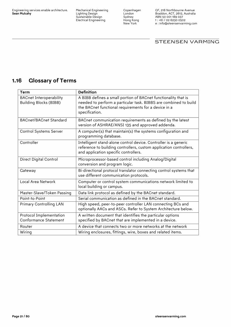
1.16 Glossary of Terms
Term Definition BACnet Interoperability Building Blocks (BIBB)
A BIBB defines a small portion of BACnet functionality that is needed to perform a particular task. BIBBS are combined to build the BACnet functional requirements for a device in a specification.
BACnet/BACnet Standard BACnet communication requirements as defined by the latest version of ASHRAE/ANSI 135 and approved addenda.
Control Systems Server A computer(s) that maintain(s) the systems configuration and programming database.
Controller Intelligent stand-alone control device. Controller is a generic reference to building controllers, custom application controllers, and application specific controllers.
Direct Digital Control Microprocessor-based control including Analog/Digital conversion and program logic.
Gateway Bi-directional protocol translator connecting control systems that use different communication protocols.
Local Area Network Computer or control system communications network limited to local building or campus.
Master-Slave/Token Passing Data link protocol as defined by the BACnet standard. Point-to-Point Serial communication as defined in the BACnet standard. Primary Controlling LAN High speed, peer-to-peer controller LAN connecting BCs and
optionally AACs and ASCs. Refer to System Architecture below.
Protocol Implementation Conformance Statement
A written document that identifies the particular options specified by BACnet that are implemented in a device.
Router A device that connects two or more networks at the network layer. Wiring Wiring enclosures, fittings, wire, boxes and related items.
Engineering services enable architecture. Sean Mulcahy
Mechanical Engineering Lighting Design Sustainable Design Electrical Engineering
Copenhagen London Sydney Hong Kong New York
GF, 218 Northbourne Avenue Braddon, ACT, 2612, Australia ABN 50 001 189 037 t : +61 / 02 6230 0502 e : [email protected]
STEENSEN VARMING
Page 22 / 80 steensenvarming.com
2.0 Part 2 – Equipment and Performance
2.1 General
Use new products that the manufacturer is currently manufacturing and selling for use in new installations. Do not use this installation as a product test site unless explicitly approved in writing by the High Court. Spare parts shall be available for at least ten years after completion of this contract.
2.2 Communications
Control products, communication media, connectors, repeaters, hubs, and routers shall comprise a BACnet IP/Ethernet based internetwork. Controller and operator interface communication shall conform to ANSI/ASHRAE Standard 135, BACnet. Install new wiring and network devices as required to provide a complete and workable control network. Each controller shall have communication ports for temporary connection to a laptop computer or other operator interface. Connection shall support memory downloads and other commissioning and troubleshooting operations. An operator interface connected to a controller shall allow the operator to interface with each internetwork controller as if directly connected. Controller information such as data, status, and control algorithms shall be viewable and editable from each internetwork controller. Inputs, outputs, and control variables used to integrate control strategies across multiple controllers shall be readable by each controller on the internetwork. Program and test all cross-controller links required to execute control strategies specified Section 4. An authorised operator shall be able to edit cross-controller links by typing a standard object address or by using a point-and-click interface. Workstations, Building Control Panels, and Controllers with real-time clocks shall use the BACnet Time Synchronization service. The System shall automatically synchronize system clocks daily from an operator-designated device via the internetwork. The system shall automatically adjust for daylight saving and standard time as applicable. The system shall be expandable to at least twice the required input and output objects with additional controllers, associated devices, and wiring. The system shall support Web services data exchange with any other system that complies with XML (extensible markup language) and SOAP (simple object access protocol) standards specified by the Web Services Interoperability Organisation (WS-I) Basic Profile 1.0 or higher. Web services support shall as a minimum be
Engineering services enable architecture. Sean Mulcahy
Mechanical Engineering Lighting Design Sustainable Design Electrical Engineering
Copenhagen London Sydney Hong Kong New York
GF, 218 Northbourne Avenue Braddon, ACT, 2612, Australia ABN 50 001 189 037 t : +61 / 02 6230 0502 e : [email protected]
STEENSEN VARMING
Page 23 / 80 steensenvarming.com
provided at the workstation or web server level and shall enable data to be read from or written to the system. The system shall support Web services read data requests by retrieving requested trend data or point values (I/O hardware points, analog value software points, or binary value software points) from any system controller or from the trend history database. The system shall support Web services write data request to each analog and binary object that can be edited through the system operator interface by downloading a numeric value to the specified object. For read or write requests, the system shall require user name and password authentication and shall support SSL (Secure Socket Layer) or equivalent data encryption. The system shall support discovery through a Web services connection or shall provide a tool available through the Operator Interface that will reveal the path/identifier needed to allow a third party Web services device to read data from or write data to any object in the system which supports this service.
2.3 Communication Protocols
Provide communication services over the BACnet IP/Ethernet communications network that results in operator interface and value passing that is transparent to the internet architecture as follows:
a) Provide facilities to enable an operator interface device connected to any one controller on the BACnet communication network to interface with all other controllers as if that interface were directly connected to the other controllers. Make data, status information, reports, system software, custom programs, etc. for all controllers available for viewing and editing from any one controller on the BACnet communication network.
b) Make all database values (e.g. objects, software variables, custom program
variables) of any one controller readable by any other controller on the BACnet communication network. Automatically perform value passing by a controller when a reference to an object name not located in that controller is entered into the controller's database. Perform inter-network value passing without the need for operator installed software to set up any communication services.
c) Make all objects and object properties easily viewed and shared on a
system wide basis.
Engineering services enable architecture. Sean Mulcahy
Mechanical Engineering Lighting Design Sustainable Design Electrical Engineering
Copenhagen London Sydney Hong Kong New York
GF, 218 Northbourne Avenue Braddon, ACT, 2612, Australia ABN 50 001 189 037 t : +61 / 02 6230 0502 e : [email protected]
STEENSEN VARMING
Page 24 / 80 steensenvarming.com
2.4 Operator Interface
Operator Interface. Web server or 2 PC-based workstations shall reside on a high-speed network with building controllers. Each workstation or each standard browser connected to server shall be able to access all system information. The Operator Workstation or server shall conform to the BACnet Operator Workstation (B-OWS) or BACnet Advanced Workstation (B-AWS) device profile as specified in ASHRAE/ANSI 135 BACnet Annex L. In addition to the primary operator interface, the system shall include a secondary 4G enabled interface and viewable on a commercially available device such as a 4G enabled tablet device. This secondary interface may be text-based and shall provide a summary of the most important data. As a minimum, the following capabilities shall be provided through this interface:
� An operator authentication system that requires an operator to log in before viewing or editing any data, and which can be configured to limit the privileges of an individual operator.
� The ability to view and acknowledge any alarm in the system. Alarms or links to alarms shall be provided on a contiguous list so the operator can quickly view all alarms.
� A summary page or pages for each piece of equipment in the system. This page shall include the current values of all critical I/O points and shall allow the operator to lock binary points on or off and to lock analog points to any value within their range.
� Navigation links that allow the operator to quickly navigate from the home screen to any piece of equipment in the system, and then return to the home screen. These links may be arranged in a hierarchical fashion, such as navigating from the home screen to a particular building, then to a specific floor in the building, and then to a specific room or piece of equipment.
2.4.1 Communication Web server or workstation and controllers shall communicate using BACnet protocol. Web server or workstation and control network backbone shall communicate using ISO 8802-3 (Ethernet) Data Link/Physical layer protocol and BACnet/IP addressing as specified in ANSI/ASHRAE 135, BACnet Annex J.
2.4.2 Hardware Each workstation or web server shall consist of the following: Computer. Industry-standard hardware shall meet or exceed DDC system manufacturer’s recommended specifications and shall meet response times specified elsewhere in this document. The following hardware requirements also apply:
a) The hard disk shall have sufficient memory to store: i. All required operator workstation software. ii. A DDC database at least twice the size of the delivered system
database. iii. One year of trend data based on the points specified to be trended
at their specified trend intervals.
Engineering services enable architecture. Sean Mulcahy
Mechanical Engineering Lighting Design Sustainable Design Electrical Engineering
Copenhagen London Sydney Hong Kong New York
GF, 218 Northbourne Avenue Braddon, ACT, 2612, Australia ABN 50 001 189 037 t : +61 / 02 6230 0502 e : [email protected]
STEENSEN VARMING
Page 25 / 80 steensenvarming.com
b) Provide additional hardware (communication ports, video drivers, network interface cards, cabling, etc.) to facilitate all control functions and software requirements specified for the DDC system.
c) Minimum hardware configuration shall include the following: i. Dual or Quad Core Processor ii. 6 GB RAM iii. 500 GB hard disk providing data at 3.0 Gb/sec iv. 16x DVD-RW drive v. Mouse vi. 27-inch 24-bit color monitor with at least 1920 x 1080 HD resolution vii. Serial, parallel, and network communication ports and cables as
required for proper DDC system operation
2.4.3 System Software Operating System. Web server or workstation shall have an industry-standard professional-grade operating system. Operating system shall meet or exceed the DDC System manufacturers minimum requirements for their software. Acceptable systems include Microsoft Windows 8, Windows 7, Microsoft Vista and Microsoft Windows XP Pro. System Graphics. The operator interface software shall be graphically based and shall include at least one graphic per piece of equipment or occupied zone, graphics for each chilled water and hot water system, and graphics that summarise conditions on each floor of each building included in this contract. Indicate thermal comfort on floor plan summary graphics using dynamic colors to represent zone temperature relative to zone setpoint.
� Functionality. Graphics shall allow operator to monitor system status, to view a summary of the most important data for each controlled zone or piece of equipment, to use point-and-click navigation between zones or equipment, and to edit setpoints and other specified parameters.
� Animation. Graphics shall be able to animate by displaying different image
files for changed object status.
� Alarm Indication. Indicate areas or equipment in an alarm condition using colour or other visual indicator.
� Format. Graphics shall be saved in an industry-standard format such as
BMP, JPEG, PNG, or GIF. Web-based system graphics shall be viewable on browsers compatible with World Wide Web Consortium browser standards. Web graphic format shall require no plug-in (such as HTML and JavaScript) or shall only require widely available no-cost plug-ins (such as Active-X and Adobe Flash).
Custom Graphics. Custom graphic files shall be created with the use of a graphics generation package furnished with the system. The graphics generation package shall be a graphically based system that uses the mouse to create and modify graphics that are saved in the same formats as are used for system graphics. Graphics Library. Furnish a complete library of standard HVAC equipment graphics such as chillers, boilers, air handlers, terminals, fan coils, and unit ventilators. This
Engineering services enable architecture. Sean Mulcahy
Mechanical Engineering Lighting Design Sustainable Design Electrical Engineering
Copenhagen London Sydney Hong Kong New York
GF, 218 Northbourne Avenue Braddon, ACT, 2612, Australia ABN 50 001 189 037 t : +61 / 02 6230 0502 e : [email protected]
STEENSEN VARMING
Page 26 / 80 steensenvarming.com
library also shall include standard symbols for other equipment including fans, pumps, coils, valves, piping, dampers, and ductwork. The library shall be furnished in a file format compatible with the graphics generation package program.
2.4.4 System Applications System shall provide the following functionality to authorised operators as an integral part of the operator interface or as stand-alone software programs. If furnished as part of the interface, the tool shall be available from each workstation or web browser interface. If furnished as a stand-alone program, software shall be installable on standard Microsoft-compatible PCs with no limit on the number of copies that can be installed under the system license. Automatic System Database Configuration. Each workstation or web server shall store on its hard disk a copy of the current system database, including controller firmware and software. Stored database shall be automatically updated with each system configuration or controller firmware or software change. Manual Controller Memory Download. Operators shall be able to download memory from the system database to each controller. System Configuration. The workstation software shall provide a method of configuring the system. This shall allow for future system changes or additions by users under proper password protection. Operators shall be able to configure the system. On-Line Help. Provide a context-sensitive, on-line help system to assist the operator in operating and editing the system. On-line help shall be available for all applications and shall provide the relevant data for that particular screen. Additional help information shall be available through the use of hypertext.
2.4.5 Security Each operator shall be required to log on to the system with user name and password in order to view, edit, add, or delete data.
� Operator Access. The user name and password combination shall define accessible viewing, editing, adding, and deleting privileges for that operator. Users with system administrator rights shall be able to create new users and edit the privileges of all existing users. System Administrators shall also be able to vary and deny each operator's privileges based on the geographic location, such as the ability to edit operating parameters in Building A, to view but not edit parameters in Building B, and to not even see equipment in Building C.
� Automatic Log Out. Automatically log out each operator if no keyboard or mouse activity is detected. This auto logoff time shall be user adjustable.
� Encrypted Security Data. Store system security data including operator passwords in an encrypted format. System shall not display operator passwords.
Provide, as a minimum, password-protected operator access for the following levels:
i. Level 1: Ability to display all point data
Engineering services enable architecture. Sean Mulcahy
Mechanical Engineering Lighting Design Sustainable Design Electrical Engineering
Copenhagen London Sydney Hong Kong New York
GF, 218 Northbourne Avenue Braddon, ACT, 2612, Australia ABN 50 001 189 037 t : +61 / 02 6230 0502 e : [email protected]
STEENSEN VARMING
Page 27 / 80 steensenvarming.com
ii. Level 2: As level 1 with ability to initiate data logging functions iii. Level 3: As level 2 with ability to change user-adjustable set-points and
time schedules iv. Level 4: As level 3 with ability to change control strategies,
schematic/graphics functions and password assignment. Ensure that password-protected operator access is set up for both operator workstations and field controllers which have an operator interface. Ensure that passwords permit at least 6 alpha/numeric characteristics. Ensure that the BMS software is protected from unauthorised entry.
2.4.6 System Diagnostics The system shall automatically monitor the operation of all building management panels and controllers. The failure of any device shall be annunciated to the operator.
2.4.7 Alarms Alarm Processing. System input and status objects shall be configurable to alarm on departing from and on returning to normal state. Operator shall be able to enable or disable each alarm and to configure alarm limits, alarm limit differentials, alarm states, and alarm reactions for each system object. Configure and enable alarm points as specified in Section 4. Alarms shall be BACnet alarm objects and shall use BACnet alarm services. Raise alarms through security system by way of a mimic panel located in the security room. Alarm Messages Alarm messages shall use the English language descriptor for the object in alarm in such a way that the operator will be able to recognise the source, location, and nature of the alarm without relying on acronyms. Alarm Reactions Operator shall be able to configure (by object) what, if any actions are to be taken during an alarm. As a minimum, the workstation or web server shall be able to log, print, start programs, display messages, send e-mail, send page, and audibly annunciate. Alarm and Event log Operators shall be able to view all system alarms and changes of state from any location in the system. Events shall be listed chronologically. An operator with the proper security level may acknowledge and delete alarms, and archive closed alarms to the workstation or web server hard disk.
Engineering services enable architecture. Sean Mulcahy
Mechanical Engineering Lighting Design Sustainable Design Electrical Engineering
Copenhagen London Sydney Hong Kong New York
GF, 218 Northbourne Avenue Braddon, ACT, 2612, Australia ABN 50 001 189 037 t : +61 / 02 6230 0502 e : [email protected]
STEENSEN VARMING
Page 28 / 80 steensenvarming.com
Binary Alarms Each binary object shall have the capability to be configured to alarm based on the operator-specified state. Provide the capability to automatically and manually disable alarming. Analog Alarms Each analog object shall have both high and low alarm limits. The operator shall be able to enable or disable these alarms. Alarm Reporting The operator shall be able to determine the action to be taken in the event of an alarm. An alarm shall be able to start programs, print, be logged in the event log, generate custom messages, and display on graphics.
2.4.8 Trend Logs The operator shall be able to configure trend sample or change of value (COV) interval, start time, and stop time for each system data object and shall be able to retrieve data for use in spreadsheets and standard database programs. Controller shall sample and store trend data and shall be able to archive data to the hard disk. Configure trends as specified in Section 4. Trends shall be BACnet trend objects. Object and Property Status and Control. Provide a method for the operator to view, and edit if applicable, the status of any object or property in the system. The status shall be available by menu, on graphics, or through custom programs.
2.4.9 Reports and Logs Operator shall be able to select, to modify, to create, and to print reports and logs. Operator shall be able to store report data in a format accessible by standard spreadsheet and word processing programs. Standard Reports. Furnish the following standard system reports:
a) Objects. System objects and current values filtered by object type, by status (in alarm, locked, normal), by equipment, by geographic location, or by combination of filter criteria.
b) Alarm Summary. Current alarms and closed alarms. System shall retain closed alarms for an adjustable period.
c) Logs. System shall log the following to a database or text file and shall retain data for an adjustable period:
i. Alarm History. ii. Trend Data. Operator shall be able to select trends to be logged. iii. Operator Activity. At a minimum, system shall log operator log in
and log out, control parameter changes, schedule changes, and alarm acknowledgment and deletion. System shall date and time stamp logged activity.
Engineering services enable architecture. Sean Mulcahy
Mechanical Engineering Lighting Design Sustainable Design Electrical Engineering
Copenhagen London Sydney Hong Kong New York
GF, 218 Northbourne Avenue Braddon, ACT, 2612, Australia ABN 50 001 189 037 t : +61 / 02 6230 0502 e : [email protected]
STEENSEN VARMING
Page 29 / 80 steensenvarming.com
2.2.9 Energy Reports System shall include an easily configured energy reporting tool that provides the capabilities described in this section.
a) The energy reporting tool shall be accessible through the same user interface (Web browser or operator workstation software) as is used to manage the BMS.
b) The energy reporting tool shall be preconfigured by the Contractor to gather and store energy demand and consumption data from each energy source that provides metered data to the BMS. Meter data shall be stored at 5 minute intervals unless otherwise specified in the Sequence of Operation provided in Section 4. This data shall be maintained in an industry standard SQL database for a period of not less than five years.
c) The energy reporting tool shall allow the operator to select an energy source and a time period of interest (day, week, month, year, or date range) and shall provide options to view the data in a table, line graph, bar graph, or pie chart. The tool shall also allow the operator to select two or more data sources and display a comparison of the energy used over this period in any of the listed graph formats, or to total the energy used by the selected sources and display that data in the supported formats.
d) The energy reporting tool shall allow the operator to select and energy source and two time periods of interest (day, week, month, year, or date range) and display a graph that compares the energy use over the two time periods in any of the graph formats listed in the previous paragraph. The tool shall also allow the operator to select multiple energy sources and display a graph that compares the total energy used by these sources over the two time periods.
e) The energy reporting tool shall allow the operator to easily generate the previously described graphs "on the fly," and shall provide an option to store the report format so the operator can select that format to regenerate the graph at a future date. The tool shall also allow the user to schedule these reports to run on a recurring basis using relative time periods, such as automatically generating a consumption report on the first Monday of each month showing consumption over the previous month. Automatically generated reports shall be archived on the server in a common industry format such as Adobe PDF or Microsoft Excel with copies e-mailed to a user editable list of recipients.
f) The energy reporting tool shall be capable of collecting and displaying data from the following types of meters:
i. Electricity ii. Gas iii. Oil iv. Chilled Water v. Potable Water vi. Heating and cooling degree days. (May be calculated from
sensor data rather than metered.) g) The user shall have the option of using Kw (Kwh) as the units for demand
and consumption reports. Multiples of these units (MWH etc.) shall be used as appropriate. All selected sources shall be automatically converted to the selected units. The user shall similarly have the option of entering facility area and occupancy hours and creating reports that are normalised on an area basis, an annual use basis, or an occupied hour basis.
Engineering services enable architecture. Sean Mulcahy
Mechanical Engineering Lighting Design Sustainable Design Electrical Engineering
Copenhagen London Sydney Hong Kong New York
GF, 218 Northbourne Avenue Braddon, ACT, 2612, Australia ABN 50 001 189 037 t : +61 / 02 6230 0502 e : [email protected]
STEENSEN VARMING
Page 30 / 80 steensenvarming.com
h) The user shall have the option of entering benchmark data for an individual facility or a group of facilities.
i) The user shall have the option of displaying any or all of the following data on any chart, line, or bar graph generated by the energy reporting tool:
i. Low/High/Average value of the metered value being displayed. ii. Heating and/or Cooling Degree Days for the time period(s)
being displayed. iii. The Environmental Index for the facilities and time periods
being displayed.
2.4.10 Environmental Index The System shall monitor all occupied zones and compile an index that provides a numerical indication of the environmental comfort within the zone. As a minimum, this indication shall be based upon the deviation of the zone temperature from the heating or cooling setpoint. If humidity is being measured within the zone then the environmental index shall be adjusted to reflect a lower comfort level for high or low humidity levels. Similarly, if carbon dioxide levels are being measured as an indication of ventilation effectiveness then the environmental index shall be adjusted to indicate degraded comfort at high carbon dioxide levels. Other adjustments may be made to the environmental index based upon additional measurements. The system shall maintain a trend of the environmental index for each zone in the trend log. The system shall also compute an average comfort index for every building included in this contract and maintain trendlogs of these building environmental indices. Similarly, the system shall compute the percentage of occupied time that comfortable conditions were maintained within the zones. Through the user interface (UI) the user shall be able to add a weighting factor to adjust the contribution of each zone to the average index based upon the floor area of the zone, importance of the zone, or other static criteria.
2.4.11 Custom Reports Operator shall be able to create custom reports that retrieve data, including archived trend data, from the system, that analyse data using common algebraic calculations, and that present results in tabular or graphical format. Reports shall be launched from the operator interface.
2.4.12 Workstation Application Editors Each PC or browser workstation shall support editing of all system applications. The applications shall be downloaded and executed at one or more of the controller panels. Controller. Provide a full-screen editor for each type of application that shall allow the operator to view and change the configuration, name, control parameters, and set points for all controllers. Scheduling. An editor for the scheduling application shall be provided at each workstation. Provide a method of selecting the desired schedule and schedule type. Exception schedules and holidays shall be shown clearly on the calendar. The start and stop times for each object shall be adjustable from this interface.
Engineering services enable architecture. Sean Mulcahy
Mechanical Engineering Lighting Design Sustainable Design Electrical Engineering
Copenhagen London Sydney Hong Kong New York
GF, 218 Northbourne Avenue Braddon, ACT, 2612, Australia ABN 50 001 189 037 t : +61 / 02 6230 0502 e : [email protected]
STEENSEN VARMING
Page 31 / 80 steensenvarming.com
Custom Application Programming. Provide the tools to create, edit, debug, and download custom programs. System shall be fully operable while custom programs are edited, compiled, and downloaded. Programming language shall have the following features:
a) Language. Language shall be graphically based and shall use function blocks arranged in a logic diagram that clearly shows control logic flow. Function blocks shall directly provide functions listed below, and operators shall be able to create custom or compound function blocks.
b) Programming Environment. Tool shall provide a full-screen, cursor-and-mouse-driven programming environment that incorporates word processing features such as cut and paste. Operators shall be able to insert, add, modify, and delete custom programming code, and to copy blocks of code to a file library for reuse in other control programs.
c) Independent Program Modules. Operator shall be able to develop independently executing program modules that can disable, enable and exchange data with other program modules.
d) Debugging and Simulation. Operator shall be able to step through the program observing intermediate values and results. Operator shall be able to adjust input variables to simulate actual operating conditions. Operator shall be able to adjust each step’s time increment to observe operation of delays, integrators, and other time-sensitive control logic. Debugger shall provide error messages for syntax and for execution errors.
e) Conditional Statements. Operator shall be able to program conditional logic using compound Boolean (AND, OR, and NOT) and relational (EQUAL, LESS THAN, GREATER THAN, NOT EQUAL) comparisons.
f) Mathematical Functions. Language shall support floating-point addition, subtraction, multiplication, division, and square root operations, as well as absolute value calculation and programmatic selection of minimum and maximum values from a list of values.
g) Variables. Operator shall be able to use variable values in program conditional statements and mathematical functions.
h) Time Variables. Operator shall be able to use predefined variables to represent time of day, day of the week, month of the year, and date. Other predefined variables or simple control logic shall provide elapsed time in seconds, minutes, hours, and days. Operator shall be able to start, stop, and reset elapsed time variables using the program language.
i) System Variables. Operator shall be able to use predefined variables to represent status and results of Controller Software and shall be able to enable, disable, and change setpoints of Controller Software as described in Controller Software section.
j) Portable Operator's Terminal. Provide all necessary software to configure an Microsoft-compatible laptop computer for use as a Portable Operator’s Terminal. Operator shall be able to connect configured Terminal to the system network or directly to each controller for programming, setting up, and troubleshooting.
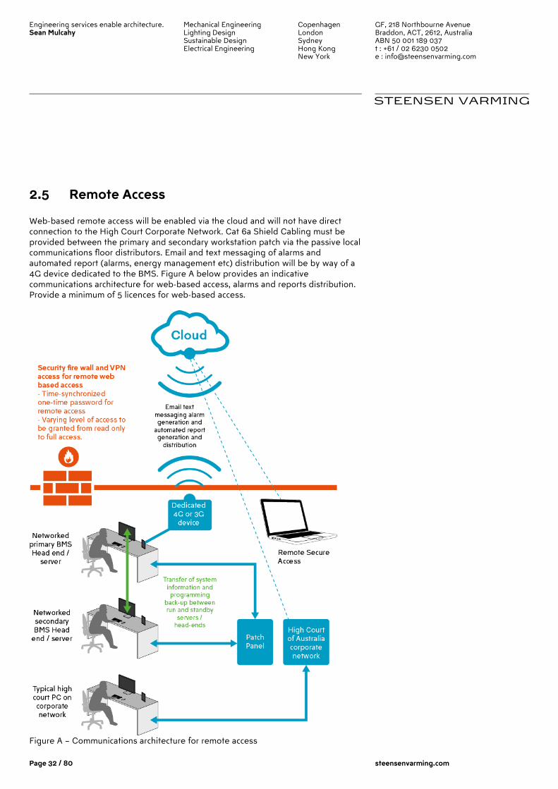
Engineering services enable architecture. Sean Mulcahy
Mechanical Engineering Lighting Design Sustainable Design Electrical Engineering
Copenhagen London Sydney Hong Kong New York
GF, 218 Northbourne Avenue Braddon, ACT, 2612, Australia ABN 50 001 189 037 t : +61 / 02 6230 0502 e : [email protected]
STEENSEN VARMING
Page 32 / 80 steensenvarming.com
2.5 Remote Access
Web-based remote access will be enabled via the cloud and will not have direct connection to the High Court Corporate Network. Cat 6a Shield Cabling must be provided between the primary and secondary workstation patch via the passive local communications floor distributors. Email and text messaging of alarms and automated report (alarms, energy management etc) distribution will be by way of a 4G device dedicated to the BMS. Figure A below provides an indicative communications architecture for web-based access, alarms and reports distribution. Provide a minimum of 5 licences for web-based access.
Figure A – Communications architecture for remote access
Engineering services enable architecture. Sean Mulcahy
Mechanical Engineering Lighting Design Sustainable Design Electrical Engineering
Copenhagen London Sydney Hong Kong New York
GF, 218 Northbourne Avenue Braddon, ACT, 2612, Australia ABN 50 001 189 037 t : +61 / 02 6230 0502 e : [email protected]
STEENSEN VARMING
Page 33 / 80 steensenvarming.com
2.6 Outstation Controllers
2.6.1 General Provide an adequate number of modular and expandable electronic controllers, either application-specific or universal type, programmed for the required functions. as required to achieve performance specified herein. Every device in the system which executes control logic and directly controls HVAC equipment must conform to a standard BACnet Device profile as specified in ANSI/ASHRAE 135, BACnet Annex L.
2.6.2 BACnet a) Building Controllers (BCs). Each BC shall conform to BACnet Building Controller
(B-BC) device profile as specified in ANSI/ASHRAE 135, BACnet Annex L, and shall be listed as a certified B-BC in the BACnet Testing Laboratories (BTL) Product Listing.
b) BACnet Communication.
i. Each BC shall reside on or be connected to a BACnet network using ISO 8802-3 (Ethernet) Data Link/Physical layer protocol and BACnet/IP addressing.
ii. BACnet routing shall be performed by BCs or other BACnet device routers as necessary to connect BCs to networks of AACs and ASCs.
iii. Each AAC shall reside on a BACnet network using ISO 8802-3 (Ethernet) Data Link/Physical layer protocol with BACnet/IP addressing, or it shall reside on a BACnet network using the ARCNET or MS/TP Data Link/Physical layer protocol.
iv. Each ASC shall reside on a BACnet network using the ARCNET or MS/TP Data Link/Physical layer protocol.
v. Each SA shall reside on a BACnet network using the ARCNET or MS/TP Data Link/Physical layer protocol.
vi. Each SS shall reside on a BACnet network using ISO 8802-3 (Ethernet) Data Link/Physical layer protocol with BACnet/IP addressing, or it shall reside on a BACnet network using ARCNET or MS/TP Data Link/Physical layer protocol.
2.6.3 Communication a) Service Port. Each controller shall provide a service communication port for
connection to a Portable Operator’s Terminal. Connection shall be extended to space temperature sensor ports where shown on drawings.
b) Signal Management. Building controller operating systems shall manage input and output communication signals to allow distributed controllers to share real and virtual object information and to allow for central monitoring and alarms.
c) Data Sharing. Each controller shall share data as required with each networked controller.
d) Stand-Alone Operation. Each piece of equipment shall be controlled by a single controller to provide stand-alone control in the event of communication failure. All I/O points specified for a piece of equipment shall be integral to its controller. Provide stable and reliable stand-alone control using default values
Engineering services enable architecture. Sean Mulcahy
Mechanical Engineering Lighting Design Sustainable Design Electrical Engineering
Copenhagen London Sydney Hong Kong New York
GF, 218 Northbourne Avenue Braddon, ACT, 2612, Australia ABN 50 001 189 037 t : +61 / 02 6230 0502 e : [email protected]
STEENSEN VARMING
Page 34 / 80 steensenvarming.com
or other method for values normally read over the network such as outdoor air conditions, supply air or water temperature coming from source equipment, etc.
2.6.4 Environment Controller hardware shall be suitable for anticipated ambient conditions. a) Controllers used outdoors or in wet ambient conditions shall be mounted in
waterproof enclosures and shall be rated for operation at -29°C to 60°C. b) Controllers used in conditioned space shall be mounted in dust-protective
enclosures and shall be rated for operation at 0°C to 50°C.
2.6.5 Keypad Provide a local keypad and display for each controller. Operator shall be able to use keypad to view and edit data. Keypad and display shall require password to prevent unauthorised use. If the manufacturer does not normally provide a keypad and display for each controller, provide the software and any interface cabling needed to use a laptop computer as a Portable Operator’s Terminal for the system.
2.6.6 Real-Time Clock Controllers that perform scheduling shall have a real-time clock.
2.6.7 Serviceability Provide diagnostic LEDs for power, communication, and processor. All wiring connections shall be made to a field-removable modular terminal strip or to a termination card connected by a ribbon cable. Each controller shall continually check its processor and memory circuit status and shall generate an alarm on abnormal operation. System shall continuously check controller network and generate alarm for each controller that fails to respond.
2.6.8 Memory a) Controller memory shall support operating system, database, and programming
requirements. b) Each controller shall retain BIOS and application programming for at least 72
hours in the event of power loss. c) Each controller shall use nonvolatile memory and shall retain BIOS and
application programming in the event of power loss. System shall automatically download dynamic control parameters following power loss.
2.6.9 Immunity to Power and Noise Controllers shall be able to operate at 90% to 110% of nominal voltage rating and shall perform an orderly shutdown below 80% nominal voltage. Operation shall be protected against electrical noise of 5 to 120 Hz and from keyed radios up to 5 W at 1 m (3 ft).
Engineering services enable architecture. Sean Mulcahy
Mechanical Engineering Lighting Design Sustainable Design Electrical Engineering
Copenhagen London Sydney Hong Kong New York
GF, 218 Northbourne Avenue Braddon, ACT, 2612, Australia ABN 50 001 189 037 t : +61 / 02 6230 0502 e : [email protected]
STEENSEN VARMING
Page 35 / 80 steensenvarming.com
2.6.10 Transformer Controller power supply shall be fused or current limiting and shall be rated at a minimum of 125% of ASC power consumption.
2.7 Controller Software
Furnish the following applications for building and energy management. All software application shall reside and operate in the system controllers. Applications shall be editable through operator workstation, web browser interface, or engineering workstation. Scheduling Provide the capability to execute control functions according to a user created or edited schedule. Each schedule shall provide the following schedule options as a minimum:
a) Weekly Schedule. Provide separate schedules for each day of the week. Each schedule shall be able to include up to 5 occupied periods (5 start-stop pairs or 10 events).
b) Exception Schedules. Provide the ability for the operator to designate any day of the year as an exception schedule. Exception schedules may be defined up to a year in advance. Once an exception schedule has executed, the system shall discard and replace the exception schedule with the standard schedule for that day of the week.
c) Holiday Schedules. Provide the capability for the operator to define up to 24 special or holiday schedules. These schedules will be repeated each year. The operator shall be able to define the length of each holiday period.
d) System Coordination. Operator shall be able to group related equipment based on function and location and to use these groups for scheduling and other applications.
Demand Limiting The demand-limiting program shall monitor building power consumption from a building power meter which generates pulse signals or a BACnet communications interface. An acceptable alternative is for the system to monitor a watt transducer or current transformer attached to the building feeder lines. When power consumption exceeds adjustable levels, system shall automatically adjust setpoints, de-energize low-priority equipment, and take other programmatic actions to reduce demand as specified in Section 4. When demand drops below adjustable levels, system shall restore loads as specified. Maintenance Management The system shall be capable of generating maintenance alarms when equipment exceeds adjustable runtime, equipment starts, or performance limits. Configure and enable maintenance alarms as specified in Section 4. Sequencing Application software shall sequence chillers, boilers, and pumps as specified in Section 4. PID Control
Engineering services enable architecture. Sean Mulcahy
Mechanical Engineering Lighting Design Sustainable Design Electrical Engineering
Copenhagen London Sydney Hong Kong New York
GF, 218 Northbourne Avenue Braddon, ACT, 2612, Australia ABN 50 001 189 037 t : +61 / 02 6230 0502 e : [email protected]
STEENSEN VARMING
Page 36 / 80 steensenvarming.com
System shall provide direct- and reverse-acting PID (proportional-integral-derivative) algorithms. Each algorithm shall have anti-windup and selectable controlled variable, setpoint, and PID gains. Each algorithm shall calculate a time-varying analogue value that can be used to position an output or to stage a series of outputs. The calculation interval, PID gains, and other tuning parameters shall be adjustable by a user with the correct security level. Staggered Start System shall stagger controlled equipment restart after power outage. Operator shall be able to adjust equipment restart order and time delay between equipment restarts. Energy Calculations The system shall accumulate and convert instantaneous power (kW) or flow rates (L/sto energy usage data. The system shall calculate a sliding-window average (rolling average). Operator shall be able to adjust window interval to 15 minutes, 30 minutes, or 60 minutes. Anti-Short Cycling All binary output objects shall be protected from short cycling by means of adjustable minimum on-time and off-time settings. On and Off Control with Differential Provide an algorithm that allows a binary output to be cycled based on a controlled variable and a setpoint. The algorithm shall be direct-acting or reverse-acting. Runtime Totalisation Provide software to totalize runtime for each binary input and output. Operator shall be able to enable runtime alarm based on exceeded adjustable runtime limit. Configure and enable runtime totalisation and alarms as specified in Section 4.
2.8 Redundancy and Reliability
2.8.1 Run and Standby Servers 2No. Server computers must be provided under a run and ’hot’ standby configuration to act as a failsafe mechanism and reliability. Each server computer are equipped with all hardware and software with complete capability to support the designated BMS tasks. Each server will coexist on the BMS network and are able to automatically assume full operation of BMS without any loss of data, alarm, or status information. The redundancy software provides full databases charges made to the primary server are propagated to the backup server without any operator intervention. Changeovers from primary to backup server must be accomplished within 10seconds, whether manually initialed or automatically initialed.
Engineering services enable architecture. Sean Mulcahy
Mechanical Engineering Lighting Design Sustainable Design Electrical Engineering
Copenhagen London Sydney Hong Kong New York
GF, 218 Northbourne Avenue Braddon, ACT, 2612, Australia ABN 50 001 189 037 t : +61 / 02 6230 0502 e : [email protected]
STEENSEN VARMING
Page 37 / 80 steensenvarming.com
Detection of any server software execution failure will cause the automatic transfer of all server functions to the backup server and will initiate a primary server failure alarm. The BMS Contractor will provide a hardware or software switch to allow the user selection of which server computer is the primary server, and which is the backup server. Such selections are made freely and at any time during the normal operation of the BMS Server System. It must possible at any time to completely remove one of the server computers for repair, maintenance or other need without disrupting normal BMS operations. BMS workstations will automatically switch the user interface and TCP/IP address to the server in control of the BMS, without operator intervention.
2.8.2 Emergency Restoration Procedure Ensure that the BMS fully restores all control and monitoring functions following an emergency shutdown period. Ensure that the strategy for phased restoration of plant operation complies with the specification. Ensure that the restoration of plant is performed within the time period specified in the Particular Specification. Ensure that start delay times can be adjusted according to the magnitude of the load.
2.8.3 Troubleshooting, Help and Assistance Provide a facility to allow the display of help text covering all operator functions and system fault conditions. Provide a facility to allow the display (including a hard copy) of:
• points list (hard and soft-points) • control strategy logic schematics.
2.9 Future system expansion
Part 4 of this specification and the control points list attached as an appendix, describe and outline the monitoring and control functional requirements for the project. In addition to the quantity of input/output points to meet these requirements – the Contractor must allow for 20% additional physical spare input/output capacity at each controller (or add-on module) for short-term future flexibility. That is 20% of each analogue input/output and digital input/output each respectively as a part of this installation. The system as an entirety must have the ability to expand by a minimum of 50% on top of the points installed from day one. That is, each controller must have the ability

Engineering services enable architecture. Sean Mulcahy
Mechanical Engineering Lighting Design Sustainable Design Electrical Engineering
Copenhagen London Sydney Hong Kong New York
GF, 218 Northbourne Avenue Braddon, ACT, 2612, Australia ABN 50 001 189 037 t : +61 / 02 6230 0502 e : [email protected]
STEENSEN VARMING
Page 38 / 80 steensenvarming.com
to expand by 50% of the total point installed in each controller through add-on module without the requirement for upgrades to the controller.
2.10 Power Supply, UPS and Line Filtering
2.10.1 General The power supply fpr the BMS and the associated data gathering and field devices need to be provided with standby power supply. The headend devices need to be connected and supported by local UPS units. All new data gather points and field devices need to be powered via new final subcircuit cabling. All devices need to be connected to the standby section of the existing power infrastructure such that are operational on the existing standby generator system.
2.10.2 Power Supplies Control transformers must be UL listed. Furnish Class 2 current-limiting type or furnish over-current protection in primary and secondary circuits for Class 2 service in accordance with NEC requirements. Limit connected loads to 80% of rated capacity. DC power supply output shall match output current and voltage requirements. Unit shall be full-wave rectifier type with output ripple of 5.0 mV maximum peak-to-peak. Regulation shall be 1.0% line and load combined, with 100-microsecond response time for 50% load changes. Unit shall have built-in over-voltage and over-current protection and shall be able to withstand 150% current overload for at least three seconds without trip-out or failure. Unit shall operate between 0°C and 50°C (32°F and 120°F). EM/RF shall meet FCC Class B and VDE 0871 for Class B and MILSTD 810C for shock and vibration. Line voltage units shall be UL recognised and CSA listed.
2.10.3 Power Line Filtering Provide internal or external transient voltage and surge suppression for workstations and controllers. Surge protection shall have:
a) Dielectric strength of 1000 V minimum b) Response time of 10 nanoseconds or less c) Transverse mode noise attenuation of 65 dB or greater d) Common mode noise attenuation of 150 dB or greater at 40–100 Hz
2.10.4 Uninterruptible Power Supply Uninterruptible power supplies will be provided with ‘back-up’ battery autonomy and be adequately sized to accommodate the electrical capacity of the following:
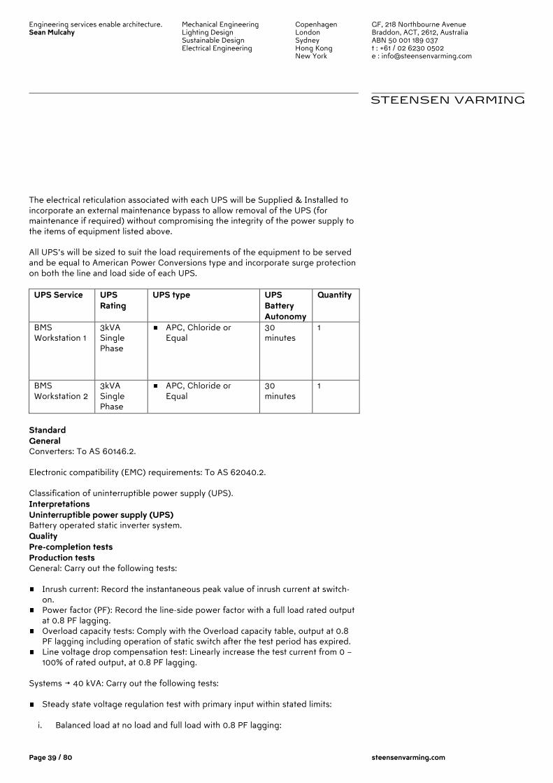
Engineering services enable architecture. Sean Mulcahy
Mechanical Engineering Lighting Design Sustainable Design Electrical Engineering
Copenhagen London Sydney Hong Kong New York
GF, 218 Northbourne Avenue Braddon, ACT, 2612, Australia ABN 50 001 189 037 t : +61 / 02 6230 0502 e : [email protected]
STEENSEN VARMING
Page 39 / 80 steensenvarming.com
The electrical reticulation associated with each UPS will be Supplied & Installed to incorporate an external maintenance bypass to allow removal of the UPS (for maintenance if required) without compromising the integrity of the power supply to the items of equipment listed above. All UPS’s will be sized to suit the load requirements of the equipment to be served and be equal to American Power Conversions type and incorporate surge protection on both the line and load side of each UPS.
UPS Service UPS Rating
UPS type UPS Battery Autonomy
Quantity
BMS Workstation 1
3kVA Single Phase
APC, Chloride or Equal
30 minutes
1
BMS Workstation 2
3kVA Single Phase
APC, Chloride or Equal
30 minutes
1
Standard General Converters: To AS 60146.2. Electronic compatibility (EMC) requirements: To AS 62040.2. Classification of uninterruptible power supply (UPS). Interpretations Uninterruptible power supply (UPS) Battery operated static inverter system. Quality Pre-completion tests Production tests General: Carry out the following tests:
Inrush current: Record the instantaneous peak value of inrush current at switch-on.
Power factor (PF): Record the line-side power factor with a full load rated output at 0.8 PF lagging.
Overload capacity tests: Comply with the Overload capacity table, output at 0.8 PF lagging including operation of static switch after the test period has expired.
Line voltage drop compensation test: Linearly increase the test current from 0 – 100% of rated output, at 0.8 PF lagging.
Systems > 40 kVA: Carry out the following tests:
Steady state voltage regulation test with primary input within stated limits:
i. Balanced load at no load and full load with 0.8 PF lagging:

Engineering services enable architecture. Sean Mulcahy
Mechanical Engineering Lighting Design Sustainable Design Electrical Engineering
Copenhagen London Sydney Hong Kong New York
GF, 218 Northbourne Avenue Braddon, ACT, 2612, Australia ABN 50 001 189 037 t : +61 / 02 6230 0502 e : [email protected]
STEENSEN VARMING
Page 40 / 80 steensenvarming.com
a. % variation from nominal voltage. b. Phase displacement. c. Crest factor ratio. d. Voltage symmetry.
ii. Unbalanced load: With 25% rated load output unbalance on each phase respectively:
a. % variation from nominal voltage. b. Phase displacement. c. Voltage symmetry at 50% unbalance.
Transient voltage regulation with primary input within stated limits:
i. Step load change: With a change of 3 even steps of 25%, 50% and 100% rated output at 5 s intervals:
a. Transient voltage % variation from nominal voltage at each step. b. Transient phase displacement at each step. c. Transient recovery time for return to steady state tolerance at each step.
Voltage waveform harmonic distortion test:
i. Distortion: At 100%, 50% and 0% of rated output, measured between phases and between each phase and neutral at the line and load terminals:
a. Total harmonic distortion in a range of 1st to 65th harmonic. b. Individual harmonic distortion in a range of 1st to 65th harmonic.
Frequency regulation tests with primary input within stated limits:
i. Slew rate. ii. Regulation: For steady state 100% and 50% rated output changes, mains
failure or restoration of mains and static bypass changeover, UPS to mains or mains to UPS:
a. % variation from nominal frequency when synchronised to reserve. b. % variation from nominal frequency when on interval crystal control. Overload capacity table
UPS rated capacity
Overload capacity test current
Duration
≤ 1200 VA 110% of rated output 10 min › 1200 VA, ‹ 6 kVA
125% of rated output 150% of rated output
6 min 1 min
≥ 6 kVA 125% of rated output 150% of rated output
7 min 10 s
Provide documentary evidence of testing and inspection noting the level of pass and failure. Submissions Shop drawings
Engineering services enable architecture. Sean Mulcahy
Mechanical Engineering Lighting Design Sustainable Design Electrical Engineering
Copenhagen London Sydney Hong Kong New York
GF, 218 Northbourne Avenue Braddon, ACT, 2612, Australia ABN 50 001 189 037 t : +61 / 02 6230 0502 e : [email protected]
STEENSEN VARMING
Page 41 / 80 steensenvarming.com
Include the following:
The UPS system general arrangement and layout with details of connections, circuit breakers, cable sizes, overall dimensions, weight, location of access doors, cable terminating locations, and necessary clearances.
Functional block diagram. The general arrangement of the remote manual by-pass switch/cabinet, and
indication/alarm panel with details of installation requirements. Type and rating of equipment items. Battery layout and associated details.
Components Operation By-pass arrangement Static by-pass: Provide an automatic, no-break, integral static by-pass switch with automatic reset to transfer the load automatically to the by-pass supply when the UPS output characteristics are outside the designated limits. Maintenance by-pass: Provide a manual by-pass switch to manually transfer the load to the mains supply, bypassing the UPS and the static by-pass switch. Harmonics Input total harmonic voltage distortion: ‹ 5%. Current limiting Provide inrush current limiting to 125% of the UPS rated load current. Protection Discrimination: Provide main circuit breakers, both input and output, within the UPS, which fully discriminate with upstream and downstream circuit breakers. Components: Provide component protection to minimise damage and downtime in the event of component failure. Include the following as appropriate:
Fuses. Circuit breakers. Overloads. Thermal sensors.
Output: Provide protection against output overload and short circuit. Ensure that output short circuits will not damage the UPS. Safety interlocks: Provide interlocks to prevent accidental damage to the UPS during maintenance or normal operation. Rectifiers/charges Input circuit breakers Type: Moulded case circuit breakers. Frame size and trip rating: Sufficient to supply the full rated load to the inverter and the battery charging load. Input current limiters Limit input current to 125% of the full rated load current. Battery chargers Type: Automatic constant voltage type, initial current maximum 10% of one-hour rate of the battery. Maximum charging current: Adjustable from 0 to 10% of the one-hour rate.
Engineering services enable architecture. Sean Mulcahy
Mechanical Engineering Lighting Design Sustainable Design Electrical Engineering
Copenhagen London Sydney Hong Kong New York
GF, 218 Northbourne Avenue Braddon, ACT, 2612, Australia ABN 50 001 189 037 t : +61 / 02 6230 0502 e : [email protected]
STEENSEN VARMING
Page 42 / 80 steensenvarming.com
Inverters Synchronising General: Provide inverters which synchronise with the a.c. input supply within 0.5 Hz. Free running: By manual switch, or automatically when the a.c. input supply is out of the designated tolerances. Provide controls which ensure that the a.c. input supply is stable and within tolerances for 30 s before automatic return from free running to synchronised running. Control and monitoring General General: Provide facilities for manual control and status monitoring of various systems within the UPS. Remote monitoring panels: Provide wall-mounted panels which indicate alarm conditions on the control and monitoring panel. Local control equipment Provide the following manual controls in an accessible location near to the UPS cabinet:
Incoming mains isolation. Battery supply isolation, if batteries are not contained within the UPS enclosure. Manual bypass, to isolate the UPS and maintain power to connected equipment.
Local status monitoring General: Provide indicator lights or a display. Function: To clearly show the status of local manual controls and protection equipment, including the following:
Incoming mains, on/off/trip. Battery supply, on/off/trip. Over temperature shut down, activated. System automatic bypass, activated.
Alarms General: Provide audible and visual alarms for the following:
Overload shutdown. High temperature warning. Over temperature shutdown. Battery contactor open. Low battery. D.C. overvoltage. Input power failed. Output overvoltage/undervoltage. Static switch on manual. Load on bypass. UPS free running.
Remote monitoring: Provide voltage-free contacts for remote alarm monitoring. Instrumentation Provide instruments, displays, keypads and selector switches, including for the following:
Engineering services enable architecture. Sean Mulcahy
Mechanical Engineering Lighting Design Sustainable Design Electrical Engineering
Copenhagen London Sydney Hong Kong New York
GF, 218 Northbourne Avenue Braddon, ACT, 2612, Australia ABN 50 001 189 037 t : +61 / 02 6230 0502 e : [email protected]
STEENSEN VARMING
Page 43 / 80 steensenvarming.com
Input voltage. Input current display. D.C. battery charge/discharge display. D.C. battery volt meter. Output and input A.C. voltage. Output and bypass A.C. current. Elapsed operating time.
Remote control and monitoring facilities General General: Provide facilities for remote monitoring and control of the UPS system, located and arranged to suit the project, including the following:
Emergency shutdown push-buttons in readily accessible locations, fitted with non-lockable covers or shrouds.
Duplication of local status monitoring indicators. Mimics: Provide displays depicting single line diagrams of the UPS system in operation. Alarms: Provide audio-visual alarms for various fault conditions for the systems within the UPS. Batteries Standard To AS/NZS 4029.2 or AS 4029.3. General Provide a battery system having an operating life of at least 10 years and suitable for operation of the UPS system. Batteries Sealed lead-acid, recombination type. Battery capacity Sufficient to provide the rated output from the UPS for the designated period of support time. Completion Spares General Supply spare parts necessary to maintain the “mean time to repair”. Packaging Package and label spare parts for long-term storage within the UPS room. Completion tests General Test run the UPS system continuously connected to the test load, for at least 48 hours. Record line and load voltage, current frequency and temperature measurements. Test loads General: Supply reactive test loads including power, control wiring and ancillary equipment. Function: To achieve the kW, and kvar and load steps necessary to demonstrate and verify the designated steady state and transient frequency and voltage responses and waveform deviation tests. Tests
Engineering services enable architecture. Sean Mulcahy
Mechanical Engineering Lighting Design Sustainable Design Electrical Engineering
Copenhagen London Sydney Hong Kong New York
GF, 218 Northbourne Avenue Braddon, ACT, 2612, Australia ABN 50 001 189 037 t : +61 / 02 6230 0502 e : [email protected]
STEENSEN VARMING
Page 44 / 80 steensenvarming.com
UPS system: Verify the following:
Correct functional operation, including mains failure and return, and operation of static and remote bypass switches.
Correct operation or indication of controls, alarms, indicators and instruments. Batteries and battery charger:
Charge the batteries for 12 hours at 10% of the one-hour rate. Simulate supply failure.
Mains failure and restoration of mains:
Static by-pass changeover test: i. % variation from nominal voltage to cause changeover. ii. Time to changeover.
Performance tests: Measure the temperature rise and efficiency performance of UPS equipment during operational trials run over 8 continuous hours at rated output. Isolating facilities tests: Demonstrate manual by-pass isolating switches and interlocking for battery and battery charger. Simulate supply failure and run UPS on battery power at rated output for the rated output support time. Test measurements During starting and test runs record transient and steady state no-load and full load waveforms. Record direct readings on test sheets and indicate time scales on oscillograms and chart records. Equipment Failure Call out Respond to call outs for breakdowns or other faults requiring corrective maintenance. Attend on site within 12 hours of notification. Rectify faults, and replace faulty materials and equipment. Provide details of warranties for UPS and Batteries.
Engineering services enable architecture. Sean Mulcahy
Mechanical Engineering Lighting Design Sustainable Design Electrical Engineering
Copenhagen London Sydney Hong Kong New York
GF, 218 Northbourne Avenue Braddon, ACT, 2612, Australia ABN 50 001 189 037 t : +61 / 02 6230 0502 e : [email protected]
STEENSEN VARMING
Page 45 / 80 steensenvarming.com
2.11 Power Metering
2.11.1 General A metering strategy will be completed by the consultant in the future as a part of separate commission and project. This future work will address all the legal and other requirements associated with the building. As part of the BMS contract there are however a number of new meter proposed as detailed within. Contractor must supply and install metering system with high level interfaces to the BMS system. All works must comply with the local supply authority and AS/NZS3000.
Supply and install local digital metering with BMS interface, within each of the sections of the switchboard, in order to monitor energy consumption. Provide new metering to the following submains supplies:
• Incoming Supply no. 1 • Incoming Supply no. 2 • Chiller No. 1 • Chiller No. 2 • Main Switch no. 3 • Main Switch no. 4 • Main Switch no. 5 • Main Switch No. 6 • PFC 1 • PFC 2
Provide new meters to the following 1. Supply No. 1 – Mechanical 2. Supply No. 2 – Light and Power 3. Electricity – Level 9 4. Electricity - Canteen As the main switchboard is in original connection the installation must be arranged such that when and if it is renewed the metering can be reused. Allow for and provide all necessary woks associated with the installation including, power outages, temporary power supplies to support critical loads. Use of Clip-on CTs to minimise power outages. Provide a remote meter panel within the Main Switchroom to house all the meters and provide space for 100% spare capacity.

Engineering services enable architecture. Sean Mulcahy
Mechanical Engineering Lighting Design Sustainable Design Electrical Engineering
Copenhagen London Sydney Hong Kong New York
GF, 218 Northbourne Avenue Braddon, ACT, 2612, Australia ABN 50 001 189 037 t : +61 / 02 6230 0502 e : [email protected]
STEENSEN VARMING
Page 46 / 80 steensenvarming.com
2.11.2 Meter Type As a minimum requirement the meters must provide Voltage, Current, PF, kWh, kVA, THD and kVAr and also provide for central connection / interfacing and monitoring via the software analysis & reporting system. The meters must have their own in-built memory in order that any loss in communication between the metering software and the meter will NOT result in the loss of any meter readings. All meters must be accuracy Class 1 and equivalent class 1 CTs. Type Schneider PM5350 or approved equal.
Accuracy compliant with IEC62053-22 class .5S for active energy Meets IEC61557-12 performance standard as PMD/S/K70/0.5 Digital I/O for monitoring and control Comprehensive measurements package, including energy and demand
monitoring (V, I, IN, F, PF, Energy, P,Q, S, Min/Max, Unbalance) PQ analysis in the form of THD and TDD measurements Powerful pre-configured, time-stamped alarms for more than 30 conditions Dot-matrix display monitors all 3 phases and neutral at the same time in English
and Chinese with other languages available via download Configurable backlight and display time-out to reduce product energy
consumption Optical revenue switch to secure revenue parameters Sealable features (V,I) 2 LED indicators Modbus communication port.
2.11.3 Meter Testing And Commissioning All meters must be calibrated in order to ensure that the correct data can be collected and recorded. Validation for the meters must include:
Meter decimal place – record where the decimal point falls in the full reading of the meter
Engineering services enable architecture. Sean Mulcahy
Mechanical Engineering Lighting Design Sustainable Design Electrical Engineering
Copenhagen London Sydney Hong Kong New York
GF, 218 Northbourne Avenue Braddon, ACT, 2612, Australia ABN 50 001 189 037 t : +61 / 02 6230 0502 e : [email protected]
STEENSEN VARMING
Page 47 / 80 steensenvarming.com
Confirm that a unit of consumption on the meter reading system corresponds to a unit of consumption on the actual meter. At least 2 readings at the same time period required.
Use a power meter to confirm that the reading on the system corresponds to an independently measured figure.
The meter logging and recording should continue to log and record the data. There are many items to record however the key ones are kWh and Amps. A check of the results should be taken against portable meter readings to reconfirm accuracy.
2.11.4 BMS Montoring and Reporting The Bms software shall be arranged to provide the following. - Power Meter Monthly Reporting BMS needs to trend and report on the information on a monthly basis in graphic format with actual figures for each meter, These include:
- kWH total for the current month shown bold in red. - kWH total for the last month shown dashed in black. - kWH total for the same month period last year shown dotted in green. - Maximum Demand ’amps’ for the current month including actual time of
peak, shown bold in red. - Maximum Demand ’amps’ for the past month including actual time of peak,
shown dashed in black - Maximum Demand ’amps’ for the same period last year including actual time
of peak, shown dotted in green. Alarms - Low level warning alarms should occur when
- a new maximum demand occurs within the past 12 months - a new peak kWh has occurred - when ’amps’ are zero ( on large supplies only >100amps).
2.12 Field Devices
2.12.1 Temperature Sensors a) Type. Temperature sensors shall be Resistance Temperature Device (RTD) b) Duct Sensors. Duct sensors shall be single point or averaging as shown.
Averaging sensors shall be a minimum of 1.5 m in length per 1 m2 of duct cross-section.
c) Immersion Sensors. Provide immersion sensors with a separable stainless steel
well. Well pressure rating shall be consistent with system pressure it will be immersed in. Well shall withstand pipe design flow velocities.
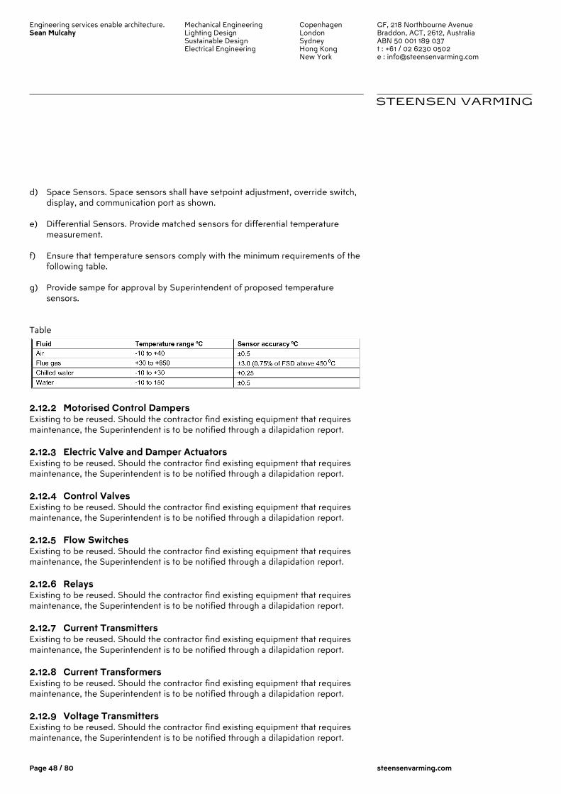
Engineering services enable architecture. Sean Mulcahy
Mechanical Engineering Lighting Design Sustainable Design Electrical Engineering
Copenhagen London Sydney Hong Kong New York
GF, 218 Northbourne Avenue Braddon, ACT, 2612, Australia ABN 50 001 189 037 t : +61 / 02 6230 0502 e : [email protected]
STEENSEN VARMING
Page 48 / 80 steensenvarming.com
d) Space Sensors. Space sensors shall have setpoint adjustment, override switch, display, and communication port as shown.
e) Differential Sensors. Provide matched sensors for differential temperature
measurement.
f) Ensure that temperature sensors comply with the minimum requirements of the following table.
g) Provide sampe for approval by Superintendent of proposed temperature
sensors.
Table
2.12.2 Motorised Control Dampers Existing to be reused. Should the contractor find existing equipment that requires maintenance, the Superintendent is to be notified through a dilapidation report.
2.12.3 Electric Valve and Damper Actuators Existing to be reused. Should the contractor find existing equipment that requires maintenance, the Superintendent is to be notified through a dilapidation report.
2.12.4 Control Valves Existing to be reused. Should the contractor find existing equipment that requires maintenance, the Superintendent is to be notified through a dilapidation report.
2.12.5 Flow Switches Existing to be reused. Should the contractor find existing equipment that requires maintenance, the Superintendent is to be notified through a dilapidation report.
2.12.6 Relays Existing to be reused. Should the contractor find existing equipment that requires maintenance, the Superintendent is to be notified through a dilapidation report.
2.12.7 Current Transmitters Existing to be reused. Should the contractor find existing equipment that requires maintenance, the Superintendent is to be notified through a dilapidation report.
2.12.8 Current Transformers Existing to be reused. Should the contractor find existing equipment that requires maintenance, the Superintendent is to be notified through a dilapidation report.
2.12.9 Voltage Transmitters Existing to be reused. Should the contractor find existing equipment that requires maintenance, the Superintendent is to be notified through a dilapidation report.
Engineering services enable architecture. Sean Mulcahy
Mechanical Engineering Lighting Design Sustainable Design Electrical Engineering
Copenhagen London Sydney Hong Kong New York
GF, 218 Northbourne Avenue Braddon, ACT, 2612, Australia ABN 50 001 189 037 t : +61 / 02 6230 0502 e : [email protected]
STEENSEN VARMING
Page 49 / 80 steensenvarming.com
2.12.10 Voltage Transformers Existing to be reused. Should the contractor find existing equipment that requires maintenance, the Superintendent is to be notified through a dilapidation report.
2.12.11 Meters General: New power meters to be installed in accordance with section 2.11 and Part 4 of this specification. There are existing meters in the building as follows: Power Meters: 1. Supply No. 1 – Mechanical 2. Supply No. 2 – Light and Power 3. Electricity – Level 9 4. Electricity - Canteen Gas Meters: 1. Gas – total 2. Gas – Canteen Water Meters: 1. Mains Supply Existing meters may be reused provided they are in good working order and compatible. Should the contractor find existing equipment that requires maintenance, the Superintendent is to be notified through a dilapidation report.
2.12.12 Hydronic Flowmeters Existing to be reused. Should the contractor find existing equipment that requires maintenance, the Superintendent is to be notified through a dilapidation report.
2.12.13 Thermal Energy Meters Existing to be reused. Should the contractor find existing equipment that requires maintenance, the Superintendent is to be notified through a dilapidation report.
2.12.14 Current Switches Existing to be reused. Should the contractor find existing equipment that requires maintenance, the Superintendent is to be notified through a dilapidation report.
2.12.15 Pressure Transducers Existing to be reused. Should the contractor find existing equipment that requires maintenance, the Superintendent is to be notified through a dilapidation report.
2.12.16 Differential Pressure Swtich Existing to be reused. Should the contractor find existing equipment that requires maintenance, the Superintendent is to be notified through a dilapidation report.
2.12.17 Occupancy Sensors Existing to be reused. Should the contractor find existing equipment that requires maintenance, the Superintendent is to be notified through a dilapidation report.
Engineering services enable architecture. Sean Mulcahy
Mechanical Engineering Lighting Design Sustainable Design Electrical Engineering
Copenhagen London Sydney Hong Kong New York
GF, 218 Northbourne Avenue Braddon, ACT, 2612, Australia ABN 50 001 189 037 t : +61 / 02 6230 0502 e : [email protected]
STEENSEN VARMING
Page 50 / 80 steensenvarming.com
3.0 Part 3 – Execution
3.1 General Workmanship and Good Practice
The project plans shall be thoroughly examined for control device and equipment locations. Any discrepancies, conflicts, or omissions shall be reported to the Superintendent for resolution before rough-in work is started. The contractor shall inspect the site to verify that equipment may be installed as shown. Any discrepancies, conflicts, or omissions shall be reported to the Superintendent for resolution before rough-in work is started. The contractor shall examine the drawings and specifications for other parts of the work. If head room or space conditions appear inadequate—or if any discrepancies occur between the plans and the contractor’s work and the plans and the work of others—the contractor shall report these discrepancies to the Superintendent and shall obtain written instructions for any changes necessary to accommodate the contractor’s work with the work of others. Any changes in the work covered by this specification made necessary by the failure or neglect of the contractor to report such discrepancies shall be made by, and at the expense of the contractor. The contractor shall protect all work and material from damage by his/her work or employees and shall be liable for all damage thus caused. The contractor shall be responsible for his/her work and equipment until finally inspected, tested, and accepted. The contractor shall protect any material that is not immediately installed. The contractor shall close all open ends of work with temporary covers or plugs during storage and construction to prevent entry of foreign objects. Install equipment, piping, and wiring/enclosures parallel to building lines (i.e. horizontal, vertical, and parallel to walls) wherever possible. Provide sufficient slack and flexible connections to allow for vibration of equipment. Verify integrity of all wiring to ensure continuity and freedom from shorts and grounds. All equipment, installation, and wiring shall comply with industry specifications and standards for performance, reliability, and compatibility and be executed in strict adherence to local codes and standard practices. Contractors shall comply with the WHS requirements outlined in the contract. As a minimum, ensure that the following safety procedures are followed:
a) Perform risk assessments and produce the resulting method statements. b) Personnel must receive adequate training in safety matters before working
on site. c) Site personnel must be issued with, and use, appropriate safety equipment.
For example: hard hat, safety boots, eye protection, ear defenders and overalls etc where appropriate.

Engineering services enable architecture. Sean Mulcahy
Mechanical Engineering Lighting Design Sustainable Design Electrical Engineering
Copenhagen London Sydney Hong Kong New York
GF, 218 Northbourne Avenue Braddon, ACT, 2612, Australia ABN 50 001 189 037 t : +61 / 02 6230 0502 e : [email protected]
STEENSEN VARMING
Page 51 / 80 steensenvarming.com
d) Isolate electrical equipment before working if live work is not necessary. Use locked-off and local isolators.
e) Cordon off live electrical panels and display warning notices. f) Personnel should stand on rubber mats when working on live panels. g) Use an adequate safety barrier when working on live equipment. h) Use a ‘permit to work’ system. i) An authority to proceed is granted before work involving rotating plant. j) Where possible use two-man working. In certain conditions two-man
working is mandatory, eg working on live equipment. k) A responsible person on site is aware of the location of the commissioning
personnel and the nature of their work.
3.2 Field Quality Control
All work, materials, and equipment shall comply with rules and regulations of applicable local, state, and federal codes. Contractor shall continually monitor the field installation for code compliance and quality of workmanship. Contractor shall have work inspection by local and/or state authorities having jurisdiction over the work.
3.3 Existing Equipment
3.3.1 Wiring The intent of the wiring scope if that the Contractor is to reuse all existig wiring to/from field devices to avoid any abortive works associated with the building masterplan and future HVAC Upgrade. The integrity of the wires and its proper application to the installation are the responsibility of the contractor. The wire shall be properly identified and tested in accordance with this specification. Unused or redundant wiring must be properly identified as such. Confirm by testing or obtain appropriate certificates from original suppliers that any existing means of network communication is of a suitable standard for satisfactory operation of the BMS. Ensure that any tests performed comply with prEN 50174. Ensure that the potential corruption of data cannot arise from: other installations not connected to, but in close proximity to,
a) the route of existing cabling b) other electrical services using existing cabling c) other adjacent cabling.
State in writing at the time of tender whether or not existing cabling is suitable. The contractor shall identify a cost per metre rate for any replacement cabling in the schedule of rates.
Engineering services enable architecture. Sean Mulcahy
Mechanical Engineering Lighting Design Sustainable Design Electrical Engineering
Copenhagen London Sydney Hong Kong New York
GF, 218 Northbourne Avenue Braddon, ACT, 2612, Australia ABN 50 001 189 037 t : +61 / 02 6230 0502 e : [email protected]
STEENSEN VARMING
Page 52 / 80 steensenvarming.com
3.3.2 Control Panels The contractor may reuse any existing local control panel to locate new equipment. All redundant equipment within these panels must be removed. Panel face cover must be patched to fill all holes caused by removal of unused equipment or replaced with new.
3.3.3 Repair Unless otherwise directed, the contractor is not responsible for repair or replacement of existing energy equipment and systems, valves, dampers, or actuators. Should the contractor find existing equipment that requires maintenance, the Superintendent is to be notified through a dilapidation report.
3.3.4 Temperature Sensor Wells All existing temperature sensor wells are to be replaced with new temperature sensors.
3.3.5 Indicator Gauges Where these devices remain and are not removed, they must be made operational and recalibrated to ensure reasonable accuracy.
3.3.6 Room Thermostats All existing room thermostats are to be removed and replaced with new temperature sensors.
3.3.7 Electronic sensors and transmitters Unless specifically noted otherwise, existing sensors and transmitters may be reused. Remove and deliver unnecessary sensors and transmitters to Superintendent.
3.3.8 Humidity Sensors The requirement for humidity control in the building has been deemed as unnecessary. The existing humidity sensors and associated control points and cabling are to be isolated and removed. Patch and finish holes and marks left by the removal of humidity sensors in walls and ducts.
3.3.9 Damper Actuators and Linkages Existing damper actuators, linkages, and appurtenances must be reused unless specifically noted otherwise. Recondition as necessary.
3.3.10 Control Valves Existing control valves may be reused unless specifically noted otherwise. Recondition as necessary.
3.3.11 Existing System Operating Schedule The mechanical system must remain in operation and shall maintain space comfort at all times between the hours of 6 a.m. and 6 p.m., Monday through Friday and Sunday between 12pm and 4pm. No modifications to the system shall cause mechanical system to be shut down for more than 15 minutes or to fail to maintain space comfort conditions during any such period. Perform cut-over of controls that cannot meet these conditions outside of operational hours.

Engineering services enable architecture. Sean Mulcahy
Mechanical Engineering Lighting Design Sustainable Design Electrical Engineering
Copenhagen London Sydney Hong Kong New York
GF, 218 Northbourne Avenue Braddon, ACT, 2612, Australia ABN 50 001 189 037 t : +61 / 02 6230 0502 e : [email protected]
STEENSEN VARMING
Page 53 / 80 steensenvarming.com
The scheduling of fans through existing or temporary time clocks or control system shall be maintained throughout the DDC system installation
3.4 Communications Cabling
3.4.1 General All existing backone and distributed communications cabling is to be removed and replaced with new cabling to required by this specification and with consideration to the staging strategy. Upon the engagement, the prospective Contractor is to allow for a detailed survey of the existing cabling routes to confirm the most appropriate route for new cabling. All cabling shall be installed in a neat and workmanlike manner. Follow manufacturer's installation recommendations for all communication cabling Do not install communication wiring in raceways and enclosures containing Class 1 or other Class 2 wiring. Maximum pulling, tension, and bend radius for the cable installation, as specified by the cable manufacturer, shall not be exceeded during installation. Contractor shall verify the integrity of the entire network following cable installation. Use appropriate test measures for each particular cable. When a cable enters or exits a building, a lightning arrestor must be installed between the lines and ground. The lighting arrestor shall be installed according to manufacturer’s instructions. All runs of communication wiring shall be unspliced length when that length is commercially available. All communication wiring shall be labelled to indicate origination and destination data. All communication wiring shall be labelled to indicate origination and destination data. BACnet MS/TP communications wiring shall be installed in accordance with ASHRAE/ANSI Standard 135. This includes but is not limited to:
� The network shall use unshielded, twisted-pair cable with characteristic impedance between 100 and 120 ohms. Distributed capacitance between conductors shall be less than 100 pF per meter.
� The maximum length of an MS/TP segment is 1200 meters with AWG 18 cable. The use of greater distances and/or different wire gauges shall comply with the electrical specifications of EIA-485.
� The maximum number of nodes per segment shall be 32, as specified in the EIA 485 standard. Additional nodes may be accommodated by the use of repeaters.
� An MS/TP EIA-485 network shall have no T connections Horizontal cabling shall be Cat 6 shielded.
Engineering services enable architecture. Sean Mulcahy
Mechanical Engineering Lighting Design Sustainable Design Electrical Engineering
Copenhagen London Sydney Hong Kong New York
GF, 218 Northbourne Avenue Braddon, ACT, 2612, Australia ABN 50 001 189 037 t : +61 / 02 6230 0502 e : [email protected]
STEENSEN VARMING
Page 54 / 80 steensenvarming.com
3.4.2 Fibre Optic Cable Maximum pulling tensions as specified by the cable manufacturer shall not be exceeded during installation. Post-installation residual cable tension shall be within cable manufacturer's specifications. All cabling and associated components shall be installed in accordance with manufacturers' instructions. Minimum cable and unjacketed fibre bend radii, as specified by cable manufacturer, shall be maintained.
3.4.3 Cable Reticulation The installation must comply with the Telecommunications Act, Australian Communications and Media Authority (ACMA) requirements and AS 3080, and must only be undertaken by licensed personnel. Documentary evidence is required to be submitted before commencement. Cable reticulation between the floors must use cable trays to link the floors. Supply and install all cable trays and reticulation pathways needed to support cables for their entire length along the proposed reticulation paths. Supply and install all cable trays within the communications rooms that are necessary to marshal the cables in a neat and orderly manner. Supply and installation of all cable trays for horizontal distribution to the work area outlets. If catenaries wires are proposed, then a maximum of twenty-five (25) F/UTP cables may be supported on one catenaries. Support the cable at a maximum of 300mm using wide, reusable, cable ties. Ratchet cable ties, which are pulled tight on the cables, are not permitted. The cable management must be fully coordinated with the other trades and provide capacity to ensure that other trades can utilise the communications cable management system. Provide adequate separation between power/lighting cabling and telecommunications including telecommunication earthing cables. Where these clearances cannot be maintained, the cables are to be shielded from Electromagnetic Interference in accordance with AS3084. Cabling within Skirting Duct is acceptable where an earthed metallic barrier separates the local circuit power and communications conductors and the maximum length of parallel run is 10m. Co-ordinate with all of the existing and planned services and structure. Co-ordinate with the other services and trades. Cables are not to be exposed or have negative impact on the architecture.
3.4.4 System Performance Requirement
Engineering services enable architecture. Sean Mulcahy
Mechanical Engineering Lighting Design Sustainable Design Electrical Engineering
Copenhagen London Sydney Hong Kong New York
GF, 218 Northbourne Avenue Braddon, ACT, 2612, Australia ABN 50 001 189 037 t : +61 / 02 6230 0502 e : [email protected]
STEENSEN VARMING
Page 55 / 80 steensenvarming.com
The horizontal cabling system is to be fully compliant with the following: Siemon Category 6A F/UTP, Power Sum NEXT compliant for 350 MHz applications. The system must be tested, verified, and certified as meeting this requirement. The system must be tested for full LINK compliance. The completed communications system will be required to support at least the following: 1. IEEE 802.3 10 Base-T Ethernet @ 10 Mbps. 2. 100Base-T Ethernet @100Mbps. 3. RS 232 Asynchronous Communications @ 19.2 Kbps. 4. ISDN (Microlink). 5. Digital PABX System Integrated Handsets 6. Analogue Voice Telephony. 7. Apple Talk LAN. 8. ISO 9314 FDDI at 100 Mbps. 9. Asynchronous Transfer Mode @155Mbps. 10. 10000Mbps Gigabit Ethernet for optic fibre cabling network backbone 11. ISDN (onRamp) 12. Megalink 13. 1000LX (1000Mbps over single mode) 14. 1000SX (Mbps over multimode) 15. 10000TX (10000Mbps over F/UTP copper).
3.4.5 Testing Electrical or Optical tests must be carried out on cables used for the distribution of Voice, Data, Text, Image and Video services. These tests are to be carried out following the termination and labelling of the cabling. Horizontal F/UTP Cabling The following checks and vendor requirements are to be undertaken by the installer on every pair of every cable. The test results are to be for the LINK as defined by AS3080. The minimum acceptable results are defined in AS3080.
� Signal to Noise Ratio (SNR) � Near End Cross Talk (NEXT) � Attenuation � Noise � Cable Route Length � Continuity � Pin Assignment � Power Sum
The testing instrument is to be EIA, TSB 67 Level II compliant, and calibration is required before use. Fibre Optic Cabling
Engineering services enable architecture. Sean Mulcahy
Mechanical Engineering Lighting Design Sustainable Design Electrical Engineering
Copenhagen London Sydney Hong Kong New York
GF, 218 Northbourne Avenue Braddon, ACT, 2612, Australia ABN 50 001 189 037 t : +61 / 02 6230 0502 e : [email protected]
STEENSEN VARMING
Page 56 / 80 steensenvarming.com
a) 100% Insertion Loss (light source and power meter) testing of all terminated fibres must be performed in both directions at 850nm for multi mode cables and 1310nm for single mode cables.
b) OTDR tests hall be performed at high wavelength, if the distance is greater than 500m at 1310nm for multi mode cables and greater than 1000m at 1550nm for single mode cables.
c) Optical loss covers the total loss between two corresponding optical ports and must include allowances for losses due to fibre, connectors, passive optical components, splices and any margin for maintenance. This loss must not exceed 5dB.
d) The optical fibre link must meet Optical Class Link performance testing as specified in AS 3080 – 1996 All fibres must obtain the vendors link certification and warranty.
Copies of all test results are to be retained and provided to the Superintendent on Handover or Milestone of the project. The test results must be provided on an electronic media in format readable by standard personal computers and as printed documents. The format must be ‘Fluke’ electronic format. A copy of the test results must also be included in the “As Installed” manuals for future reference, in accordance with the Contract conditions.
3.5 Installation of Temperature Sensors
Install sensors in accordance with the manufacturer's recommendations. Mount sensors rigidly and adequately for environment within which the sensor operates. Existing cabling is to be reused in order to minimise the impacts upon heritage ceiling and wall fabric. Room temperature sensors shall be installed on concealed junction boxes properly supported by wall framing. All wires attached to sensors shall be sealed in their raceways or in the wall to stop air transmitted from other areas from affecting sensor readings. Sensors used in mixing plenums and hot and cold decks shall be of the averaging type. Averaging sensors shall be installed in a serpentine manner vertically across the duct. Each bend shall be supported with a capillary clip. Low-limit sensors used in mixing plenums shall be installed in a serpentine manner horizontally across duct. Each bend shall be supported with a capillary clip. Provide 3 m of sensing element for each 1 m2 of coil area. All pipe-mounted temperature sensors shall be installed in wells. Install liquid temperature sensors with heat-conducting fluid in thermal wells. Install outdoor air temperature sensors on South wall, complete with sun shield at designated location.
Engineering services enable architecture. Sean Mulcahy
Mechanical Engineering Lighting Design Sustainable Design Electrical Engineering
Copenhagen London Sydney Hong Kong New York
GF, 218 Northbourne Avenue Braddon, ACT, 2612, Australia ABN 50 001 189 037 t : +61 / 02 6230 0502 e : [email protected]
STEENSEN VARMING
Page 57 / 80 steensenvarming.com
3.6 Warning Labels
Permanent warning labels shall be affixed to all equipment that can be automatically started by the control system. Labels shall use white lettering (12-point type or larger) on a red background. Warning labels shall read as follows.
C A U T I O N This equipment is operating under automatic control and may start or stop at any
time without warning. Switch disconnect to"Off"position before servicing. Permanent warning labels shall be affixed to all motor starters and control panels that are connected to multiple power sources utilizing separate disconnects. Labels shall use white lettering (12-point type or larger) on a red background. Warning labels shall read as follows.
C A U T I O N This equipment is fed from more than one power source with separate disconnects.
Disconnect all power sources before servicing.
3.7 Labelling of Hardware and Wiring
All wiring and cabling, including that within factory-fabricated panels shall be labeled at each end within 5 cm of termination with control system address or termination number. Permanently label or code each point of field terminal strips to show the instrument or item served. Identify control panels with minimum 1 cm letters on laminated plastic nameplates. Identify all other control components with permanent labels. All plug-in components shall be labeled such that label removal of the component does not remove the label. Identify room sensors related to terminal boxes or valves with nameplates. Label references shall match record documents.
3.8 Controllers
Provide a separate controller for each HVAC or other system. A DDC controller may control more than one system provided that all points associated with the system are assigned to the same DDC controller. Points used for control loop reset, such as outside air or space temperature, are exempt from this requirement.
Engineering services enable architecture. Sean Mulcahy
Mechanical Engineering Lighting Design Sustainable Design Electrical Engineering
Copenhagen London Sydney Hong Kong New York
GF, 218 Northbourne Avenue Braddon, ACT, 2612, Australia ABN 50 001 189 037 t : +61 / 02 6230 0502 e : [email protected]
STEENSEN VARMING
Page 58 / 80 steensenvarming.com
Building Controllers and Custom Application Controllers shall be selected to provide the required I/O point capacity required to monitor all of the hardware points listed Section 4.
3.9 Programming
Provide sufficient internal memory for the specified sequences of operation and trend logging.
3.9.1 Point Naming Name points as shown on the equipment points list provided with each sequence of operation. If character limitations or space restrictions make it advisable to shorten the name. Where multiple points with the same name reside in the same controller, each point name may be customized with its associated Program Object number. For example, "Zone Temp 1" for Zone 1, "Zone Temp 2" for Zone 2.
3.9.2 Software Programming Provide programming for the system and adhere to the sequences of operation provided. All other system programming necessary for the operation of the system, but not specified in this document, also shall be provided by the contractor. Embed into the control program sufficient comment statements to clearly describe each section of the program. The comment statements shall reflect the language used in the sequences of operation. Use the appropriate technique based on the following programming types:
a) Text-based: i. Must provide actions for all possible situations ii. Must be modular and structured iii. Must be commented
b) Graphic-based: i. Must provide actions for all possible situations ii. Must be documented
c) Parameter-based: i. Must provide actions for all possible situations ii. Must be documented
3.9.3 Operator Interface. Standard Graphics: Provide graphics for all mechanical systems and floor plans of the building. This includes each chilled water system, hot water system, chiller, boiler, air handler, and all terminal equipment. Point information on the graphic displays shall dynamically update. Show on each graphic all input and output points for the system. Also show relevant calculated points such as setpoints. As a minimum, show on each equipment graphic the input and output points and relevant calculated points as indicated on the applicable Points List in Section 4. The contractor shall provide all the labour necessary to install, initialize, start up, and troubleshoot all operator interface software and its functions as described in this
Engineering services enable architecture. Sean Mulcahy
Mechanical Engineering Lighting Design Sustainable Design Electrical Engineering
Copenhagen London Sydney Hong Kong New York
GF, 218 Northbourne Avenue Braddon, ACT, 2612, Australia ABN 50 001 189 037 t : +61 / 02 6230 0502 e : [email protected]
STEENSEN VARMING
Page 59 / 80 steensenvarming.com
section. This includes any operating system software, the operator interface database, and any third-party software installation and integration required for successful operation of the operator interface.
3.10 Testing and Commissioning
3.10.1 Start-up Testing All testing listed in this article shall be performed by the contractor and shall make up part of the necessary verification of an operating control system. This testing shall be completed before the Superintendent is notified of the system demonstration. The contractor shall furnish all labor and test apparatus required to calibrate and prepare for service of all instruments, controls, and accessory equipment furnished under this specification. Verify that all control wiring is properly connected and free of all shorts and ground faults. Verify that terminations are tight. Enable the control systems and verify calibration of all input devices individually. Perform calibration procedures according to manufacturers’ recommendations. Verify that all binary output devices (relays, solenoid valves, two-position actuators and control valves, magnetic starters, etc.) operate properly and that the normal positions are correct. Verify that all analogue output devices (I/Ps, actuators, etc.) are functional, that start and span are correct, and that direction and normal positions are correct. The contractor shall check all control valves and automatic dampers to ensure proper action and closure. The contractor shall make any necessary adjustments to valve stem and damper blade travel. Verify that the system operation adheres to the sequences of operation. Simulate and observe all modes of operation by overriding and varying inputs and schedules. Tune all DDC loops. Alarms and Interlocks:
a) Check each alarm separately by including an appropriate signal at a value that will trip the alarm.
b) Interlocks shall be tripped using field contacts to check the logic, as well as to ensure that the fail-safe condition for all actuators is in the proper direction.
c) Interlock actions shall be tested by simulating alarm conditions to check the initiating value of the variable and interlock action
3.11 Demonstration and Acceptance
3.11.1 Demonstration
Engineering services enable architecture. Sean Mulcahy
Mechanical Engineering Lighting Design Sustainable Design Electrical Engineering
Copenhagen London Sydney Hong Kong New York
GF, 218 Northbourne Avenue Braddon, ACT, 2612, Australia ABN 50 001 189 037 t : +61 / 02 6230 0502 e : [email protected]
STEENSEN VARMING
Page 60 / 80 steensenvarming.com
Prior to acceptance, the control system shall undergo a series of performance tests to verify operation and compliance with this specification. These tests shall occur after the Contractor has completed the installation, started up the system, and performed his/her own tests. The tests described in this section are to be performed in addition to the tests that the contractor performs as a necessary part of the installation, start-up, and debugging process and as specified in the "Control System Checkout and Testing" article of this specification. The Consultant will be present to observe and review these tests. The Consultant shall be notified at least 10 days in advance of the start of the testing procedures. The demonstration process shall follow that approved in Part 1, "Submittals." The approved checklists and forms shall be completed for all systems as part of the demonstration. The contractor shall provide at least two persons equipped with two-way communication and shall demonstrate actual field operation of each control and sensing point for all modes of operation including day, night, occupied, unoccupied, fire/smoke alarm, seasonal changeover, and power failure modes. The purpose is to demonstrate the calibration, response, and action of every point and system. Any test equipment required to prove the proper operation shall be provided by and operated by the contractor. As each control input and output is checked and verified, the contractor shall maintain a log showing the date, technician’s initials, and any corrective action taken or needed. Demonstrate compliance with Part 1, "System Performance." Demonstrate compliance with sequences of operation through all modes of operation. Demonstrate complete operation of operator interface. Additionally, the following items shall be demonstrated:
a) DDC loop response. The contractor shall supply trend data output in a graphical form showing the step response of each DDC loop. The test shall show the loop’s response to a change in set point, which represents a change of actuator position of at least 25% of its full range. The sampling rate of the trend shall be from 10 seconds to 3 minutes, depending on the speed of the loop. The trend data shall show for each sample the set point, actuator position, and controlled variable values. Any loop that yields unreasonably under-damped or over-damped control shall require further tuning by the Contractor.
b) Demand limiting. The contractor shall supply a trend data output showing the action of the demand limiting algorithm. The data shall document the action on a minute-by-minute basis over at least a 30-minute period. Included in the trend shall be building kW, demand limiting set point, and the status of sheddable equipment outputs.
c) Optimum start/stop. The contractor shall supply a trend data output showing the capability of the algorithm. The change-of-value or change-of-
Engineering services enable architecture. Sean Mulcahy
Mechanical Engineering Lighting Design Sustainable Design Electrical Engineering
Copenhagen London Sydney Hong Kong New York
GF, 218 Northbourne Avenue Braddon, ACT, 2612, Australia ABN 50 001 189 037 t : +61 / 02 6230 0502 e : [email protected]
STEENSEN VARMING
Page 61 / 80 steensenvarming.com
state trends shall include the output status of all optimally started and stopped equipment, as well as temperature sensor inputs of affected areas.
d) Interface to the building fire alarm system. e) Operational logs for each system that indicate all set points, operating
points, valve positions, mode, and equipment status shall be submitted to the Superintendent/Consultant. These logs shall cover three 48-hour periods and have a sample frequency of not more than 10 minutes. The logs shall be provided in both printed and disk formats.
f) Any tests that fail to demonstrate the operation of the system shall be repeated at a later date. The contractor shall be responsible for any necessary repairs or revisions to the hardware or software to successfully complete all tests.
3.11.2 Acceptance All tests described in this specification shall have been performed to the satisfaction of both the Consultant and Superintendent prior to the acceptance of the control system as meeting the requirements of completion. Any tests that cannot be performed due to circumstances beyond the control of the contractor may be exempt from the completion requirements if stated as such in writing by the Superintendent. Such tests shall then be performed as part of the warranty. The system shall not be accepted until all forms and checklists completed as part of the demonstration are submitted and approved as required in the relevant ‘submittals’ part of this specification.
3.12 Cleaning
The contractor shall clean up all debris resulting from his/her activities daily. The contractor shall remove all cartons, containers, crates, etc., under his/her control as soon as their contents have been removed. Waste shall be collected and placed in a designated location. At the completion of work in any area, the contractor shall clean all work, equipment, etc., keeping it free from dust, dirt, and debris, etc. At the completion of work, all equipment furnished under this section shall be checked for paint damage, and any factory-finished paint that has been damaged shall be repaired to match the adjacent areas. Any cabinet or enclosure that has been deformed shall be replaced with new material and repainted to match the adjacent areas.
3.13 Maintenance
Perform BMS maintenance in accordance with the relevant sections of: BMS Maintenance Support Services, GN 4/2001, BSRIA ISBN 0 86022 573 9
Engineering services enable architecture. Sean Mulcahy
Mechanical Engineering Lighting Design Sustainable Design Electrical Engineering
Copenhagen London Sydney Hong Kong New York
GF, 218 Northbourne Avenue Braddon, ACT, 2612, Australia ABN 50 001 189 037 t : +61 / 02 6230 0502 e : [email protected]
STEENSEN VARMING
Page 62 / 80 steensenvarming.com
Ensure that the maintenance provided covers:
a) software upgrades b) data backup and archiving c) documentation upkeep d) emergency call out (call out period defined in the Particular e) Specification) f) check operation of field controllers and communication g) networks h) check control, alarm and data logging functions i) checking of sensors for satisfactory accuracy j) proper operation of actuators k) assessment of plant control actions and rectification of poor l) performance m) check correct operation of occupant controllers n) that necessary upgrades/changes to maintain the required o) functionality of any gateways are carried out.
Provide a quotation for a one year and five year comprehensive maintenance contract as a part of the RFT returnable pricing schedules. Ensure that the quotation is based on identified maintenance activities and details any activities not covered by the contract.
Engineering services enable architecture. Sean Mulcahy
Mechanical Engineering Lighting Design Sustainable Design Electrical Engineering
Copenhagen London Sydney Hong Kong New York
GF, 218 Northbourne Avenue Braddon, ACT, 2612, Australia ABN 50 001 189 037 t : +61 / 02 6230 0502 e : [email protected]
STEENSEN VARMING
Page 63 / 80 steensenvarming.com
4.0 Part 4 –Control Strategies
4.1 General
This specification part provides the design intent control and monitoring functional requirements for the key mechanical, vertical transportation, electrical, hydraulic and (monitoring only of) fire services systems and services to be incorporated into the new BMS.
4.2 Mechanical Services
4.2.1 Global Control Provide dedicated commands to globally control plant as required for site testing and commissioning programmes including:
a) Global manual control of the positions of chilled water and condenser water control valves on an area by area
b) basis to suit water side commissioning; and c) Temporary manual or time programmed stop/start functions that do not
require deletion or modification of d) main control algorithms.
The general control strategies as detailed below shall generally be used for all plant unless nominated otherwise.
4.2.2 Global Shut-down All equipment controlled by BMS system shall have the facility to be shut down via a global shut down signal unless noted otherwise.
4.2.3 Global Re-start All equipment controlled by BMS system shall have the facility to be restarted via a global re-start signal unless noted otherwise.
4.2.4 Variable speed drive interfaces Variable Speed Drive (VSD) Interface Monitor: Current VSD status and operating conditions shall be monitored through its communications interface port. The interface shall monitor and trend the points as shown on the Points List.
4.2.5 Weather Station Provide a new self-contained, weather station unit that incorporates a purpose built data logger sensing rainfall, air temperature, relative humidity, wind speed, wind direction, and solar radiation. Outside Air Conditions: The controller shall monitor the outside air temperature and humidity and calculate the outside air enthalpy on a continual basis. These values shall be made available to the system at all times.

Engineering services enable architecture. Sean Mulcahy
Mechanical Engineering Lighting Design Sustainable Design Electrical Engineering
Copenhagen London Sydney Hong Kong New York
GF, 218 Northbourne Avenue Braddon, ACT, 2612, Australia ABN 50 001 189 037 t : +61 / 02 6230 0502 e : [email protected]
STEENSEN VARMING
Page 64 / 80 steensenvarming.com
Alarm shall be generated as follows: • Sensor Failure: Sensor reading indicates shorted or disconnected
sensor. In the event of a sensor failure, an alternate outside air conditions sensor shall be made available to the system without interruption in sensor readings.
If an OA Temp Sensor cannot be read, a default value of 18.5°C will be used. If an OA Humidity Sensor cannot be read, a default value of 50 % will be used. Outside Air Temperature History: The controller shall monitor and record the high and low temperature readings for the outside air. These readings shall be recorded on a daily, month-to-date, and year-to-date basis.
4.2.6 Chilled water systems The chilled water system consists of 2 chillers with dedicated primary only pumping arrangement including 2 cooling towers with 2No. primary & 2No. secondary condenser water pumps and cooling tower fans driven by VSD’s. Cooling-call - established
� the cooling-call shall be established based on a) valve/s position ie open > [40]% for more than [10] minutes
� provision shall be provided so that cooling-call can be established if a cooling valve or a number of cooling valves open for more than [40]% for more than [10] minutes
Cooling-call – no longer established
� the cooling-call shall no longer established when all active valves are opened < [10]% for more than [5] minutes
� provision shall be provided so that cooling-call can be established if a cooling valve or a number of cooling valves open for more than [40]% for more than [10] minutes
Chilled water system start
� the chilled water system’s starting processes shall be enabled once a cooling-call is established
� provision shall be provided so the chilled water system’s starting processes can be enabled via after-hour operation providing cooling-call has been established
� the controls shall be configured so that if a chiller is manually switched on via the chiller’s control panel; the associated pumps, valves etc shall operate as under system’s normal operation
Chilled water system stop
� the chilled water system shall shut down once the cooling-call is no longer established
� provision shall be provided to shut down the chilled water system’s operation if a local fire alarm detector is being activated
Chiller operation

Engineering services enable architecture. Sean Mulcahy
Mechanical Engineering Lighting Design Sustainable Design Electrical Engineering
Copenhagen London Sydney Hong Kong New York
GF, 218 Northbourne Avenue Braddon, ACT, 2612, Australia ABN 50 001 189 037 t : +61 / 02 6230 0502 e : [email protected]
STEENSEN VARMING
Page 65 / 80 steensenvarming.com
� the chillers and associated plants shall operate on a lead/lag operation based on [120] hrs difference
� the lead/lag operation change-over shall occur during system’s start-up, stage-down or system’s fault
Chiller enable
� the lead chiller’s starting processes shall be enabled once a cooling-call is established
� lead chiller’s associated motorised valves open (if any); then � chilled and condenser water pumps start; and � once flows are confirmed � chiller starts via enable signal from BMS � the chiller shall load/unload via its own inbuilt control
Chiller disable
� the operating chiller shall be disabled once the cooling-call is no longer established
� the enable signal to the chiller from the BMS should be disabled; and � the associated pumps shall run on for [1] minutes; and � once the [1] minute expires the pumps shall shut down; and � the associated valve/s are also driven to the closed position
Chiller stage-up
� the chiller shall stage-up when the field common return chilled water temp is [3]ᴼC above the chiller’s designed entering chilled water temp set-point for [10] minutes
� provision to be provided so that the chilled water pumps vary their speed varying the flow rate across the evaporator (when VSDs are added to the chilled water pumps) to maintain the system’s DP set-point
� provision shall be provided to include supply chilled water temp re-set via HLI calculation
Chiller stage-down
� the chiller shall stage-down when the field common return chilled water temp is [1] ᴼC below the chiller’s designed entering water temp set-point
Cooling tower operation
� both cooling towers shall operate together at all times � the increase in condenser water volume means that cooler condenser water
entering the chillers increasing the chiller’s COP; also � ensuring condenser water continuously moving minimising dead-leg and
legionella bacteria growth Cooling tower floating leaving water temp set-point
� provided that ambient temp and humidity sensors are being installed in order to obtain the ambient wet-bulb; the
� cooling-tower leaving water temp set-point shall be [2] ᴼC above the ambient wet-bulb temperature
Engineering services enable architecture. Sean Mulcahy
Mechanical Engineering Lighting Design Sustainable Design Electrical Engineering
Copenhagen London Sydney Hong Kong New York
GF, 218 Northbourne Avenue Braddon, ACT, 2612, Australia ABN 50 001 189 037 t : +61 / 02 6230 0502 e : [email protected]
STEENSEN VARMING
Page 66 / 80 steensenvarming.com
� -the minimum ambient wet-bulb temp to be used shall be [15] ᴼC ie the minimum cooling tower leaving water temp set-point shall be [17] ᴼC DB
� if ambient wet-bulb can’t be obtained then the cooling tower leaving water temp set-point shall be [2] ᴼC above ambient DB-temp but [18] ᴼC shall be the minimum ambient DB temp to be used
Cooling tower fans control
� the CT-fans shall vary their speed together to maintain the cooling towers leaving water temp set-point
Chilled water systems fault
� all faults associated with the chilled water system’s associated plants ie chiller, pumps, valves, c-towers etc shall raise an alarm on the BMS front-end and at the same time sends an SMS / Text message to relevant person/s so the fault/s can be addressed
� the person/s receiving the alarm message via the BMS auto dial-out shall be approved by the High Court
� the person/s responsible for addressing the fault/s shall ensure that the problem is actioned in no less than [2] hours form when message received
4.2.7 Heating hot water systems Heating hot water system
� The heating hot water system consists of 2No. - condensing boilers, 2No. -primary & 2No. secondary hot water pumps with each a VSD and 2 dilution supply air fans
� Currently the operation of the boilers and associated plant equipment are controlled via a stand-alone control system except the secondary hot water pumps which are controlled via the main BMCS.
� Note – The operation of the boilers and all associated plant equipment ie primary & secondary hot water pumps including the dilution fans shall be controlled via the BMS. The boilers shall load/unload including cycle-off via their individual inbuilt control systems
� the dilution supply air fans at the moment are each enabled together with each associated boiler being enabled; the existing control operation shall be reused; however, provision to be provided so that the dilution fans vary their speed to maintain a discharge air temp set-point which shall be later determined
� VSDs had been fitted to the secondary hot water pumps but they are not programmed to vary their speed; they currently run at a fixed speed when enabled
Heating-call - established
� the heating-call shall be established based on a) valve/s position ie open > [40]% for more than [10] minutes
� provision shall be provided so that heating-call can be established if a heating valve or a number of heating valves open > than [40]% for more than [10] minutes
� provision to include/exclude ambient temperature boiler-start “lock-out” ie if ambient temp is ≥ than [25] ºC

Engineering services enable architecture. Sean Mulcahy
Mechanical Engineering Lighting Design Sustainable Design Electrical Engineering
Copenhagen London Sydney Hong Kong New York
GF, 218 Northbourne Avenue Braddon, ACT, 2612, Australia ABN 50 001 189 037 t : +61 / 02 6230 0502 e : [email protected]
STEENSEN VARMING
Page 67 / 80 steensenvarming.com
Heating-call – no longer established
� the heating-call shall no longer established when all active heating valves are opened < [10]% for more than [5] minutes
� provision shall be provided so that heating-call can no longer be established if a heating valve or a number of heating valves open < than [10]% for more than [5] minutes
Heating hot water system start
� the heating hot water system’s starting processes shall be enabled once a heating-call is established
� provision shall be provided so the heating hot water system’s starting processes can be enabled via after-hour operation providing heating-call has been established
� the controls shall be configured so that if a boiler is manually switched on via the boiler’s control panel; the associated pumps, valves etc shall operate as under system’s normal operation
Heating hot water system stop
� the heating hot water system shall shut down once the heating-call is no longer established
� provision shall be provided to shut down the heating hot water system’s operation if a local fire alarm detector is being activated
Boilers operations
� the boilers and associated plants shall operate on a lead/lag operation based on [120] hrs difference
� the lead/lag operation change-over shall occur during system’s start-up, stage-down or system’s fault
Boiler enable
� the heating hot water system’s starting processes shall be enabled once a heating-call is established
� the lead boiler’s associated motorised valve/s and pumps shall operate in sequence to ensure smooth/effective system’s operation
� the flow across the boiler is to be confirmed prior to the enable signal is sent via the BMS to the boiler to start
� the boiler shall load/unload via its own inbuilt control including cycling-off Boiler disable
� the operating boiler shall be disabled once the heating-call is no longer established
� the associated pump shall run on for [1] minutes; � the pumps shall shut down and then associated valve is driven to the close
position Boiler stage-up
� the boiler shall stage-up when the field common return hot water temp is [10] ºC below the boiler’s designed entering hot water temp set-point for [10] minutes
� the lead and lag boilers shall together load/unload to maintain the boilers leaving water temp set-point providing the return hot water temp is within the boiler’s design entering water temp set-point
Engineering services enable architecture. Sean Mulcahy
Mechanical Engineering Lighting Design Sustainable Design Electrical Engineering
Copenhagen London Sydney Hong Kong New York
GF, 218 Northbourne Avenue Braddon, ACT, 2612, Australia ABN 50 001 189 037 t : +61 / 02 6230 0502 e : [email protected]
STEENSEN VARMING
Page 68 / 80 steensenvarming.com
� provision shall be provided to include supply hot water temp set-point re-set via HLI calculation
Boiler stage-down
� The boilers shall stage-down when the field common return hot water temp is [3] ºC above the boiler’s designed entering water temp set-point
Heating hot water systems fault
� all faults associated with the heating hot water system’s associated plants ie boiler, pumps, valves, sensors etc shall raise an alarm on the BMS front-end and at the same time sends a SMS / Text message to relevant person/s so the fault/s can be addressed
� the person/s receiving the alarm message via the BMS auto dial-out shall be approved by the High Court
� the person/s responsible for addressing the fault/s shall ensure that the problem is actioned in no less than [2] hours from when message received
Flue dilution fans operation
� the flue dilution fans are not installed with VSDs � the flue dilution fans shall operate together with associated boiler when
enabled � the flue dilution fans existing control operation shall remain ie on/off � provision to be provided to enable the fans to vary their speed when VSDs
are added
4.2.8 Air handling unit systems Multizone AHU’s with economy cycle Run Conditions - Scheduled: The unit shall run based upon an operator adjustable schedule. Emergency Shutdown: The unit shall shut down and generate an alarm upon receiving an emergency shutdown signal. AHU Optimal Start: The unit shall start prior to scheduled occupancy based on the time necessary for the zones to reach their occupied setpoints. The start time shall automatically adjust based on changes in outside air temperature and zone temperatures. Supply Fan: The supply fan shall run anytime the unit is commanded to run, unless shutdown on safeties. To prevent short cycling, the supply fan shall have a user definable (adj.) minimum runtime. Alarms shall be provided as follows:
� Supply Fan Failure: Commanded on, but the status is off. � Supply Fan in Hand: Commanded off, but the status is on. � Supply Fan Runtime Exceeded: Status runtime exceeds a user definable
limit (adj.).
Engineering services enable architecture. Sean Mulcahy
Mechanical Engineering Lighting Design Sustainable Design Electrical Engineering
Copenhagen London Sydney Hong Kong New York
GF, 218 Northbourne Avenue Braddon, ACT, 2612, Australia ABN 50 001 189 037 t : +61 / 02 6230 0502 e : [email protected]
STEENSEN VARMING
Page 69 / 80 steensenvarming.com
Return Fan: The return fan shall run whenever the supply fan runs. Alarms shall be provided as follows:
� Return Fan Failure: Commanded on, but the status is off. � Return Fan in Hand: Commanded off, but the status is on. � Return Fan Runtime Exceeded: Status runtime exceeds a user definable
limit (adj.). Cooling Supply Air Temperature Setpoint - Optimised: The cooling supply air temperature setpoint shall be reset using a trim and respond algorithm based on zone cooling requirements. If there is a demand for cooling then the setpoint shall be reset to a lower value (adj.). If the demand for cooling decreases then the setpoint shall reset to a higher value (adj.). Once the zones are satisfied then the setpoint shall gradually moderate over time to reduce cooling energy use. The supply air temperature setpoint shall be reset based on zone cooling requirements as follows:
� The initial supply air temperature setpoint shall be 13°C (adj.). � As cooling demand increases, the setpoint shall incrementally reset down to
a minimum of 11.5°C (adj.). � As cooling demand decreases, the setpoint shall incrementally reset up to a
maximum of 22°C (adj.). Cooling Coil Valve: The controller shall measure the cooling supply air temperature and modulate the cooling coil valve to maintain its cooling setpoint. The cooling shall be enabled whenever:
� Outside air temperature is greater than 15.5°C (adj.). � AND the economizer (if present) is disabled or fully open. � AND the supply fan status is on.
Alarms shall be provided as follows:
� High Cooling Supply Air Temp: If the cooling supply air temperature is 3°C (adj.) greater than setpoint.
Heating Supply Air Temperature Setpoint - Optimised: The heating supply air temperature setpoint shall be reset using a trim and respond algorithm based on zone heating requirements. If there is a demand for heating then the setpoint shall be reset to a higher value (adj.). If the demand for heating decreases then the setpoint shall reset to a lower value (adj.). Once the zones are satisfied then the setpoint shall gradually moderate over time to reduce heating energy use. The supply air temperature setpoint shall be reset based on zone heating requirements as follows:
� The initial supply air temperature setpoint shall be 28°C (adj.). � As heating demand increases, the setpoint shall incrementally reset up to a
maximum of 33°C (adj.). � As heating demand decreases, the setpoint shall incrementally reset down
to a minimum of 22°C (adj.).
Engineering services enable architecture. Sean Mulcahy
Mechanical Engineering Lighting Design Sustainable Design Electrical Engineering
Copenhagen London Sydney Hong Kong New York
GF, 218 Northbourne Avenue Braddon, ACT, 2612, Australia ABN 50 001 189 037 t : +61 / 02 6230 0502 e : [email protected]
STEENSEN VARMING
Page 70 / 80 steensenvarming.com
Heating Coil Valve: The controller shall measure the heating supply air temperature and modulate the heating coil valve to maintain its setpoint. The heating shall be enabled whenever:
� Outside air temperature is less than 18.5°C (adj.). � AND the supply fan status is on.
The heating coil valve shall open whenever:
� Heating supply air temperature drops from 4.5°C to 1.5°C (adj.). Alarms shall be provided as follows:
� High Heating Supply Air Temp: If the heating supply air temperature is greater than 35°C (adj.).
� Low Heating Supply Air Temp: If the heating supply air temperature is 3°C (adj.) less than setpoint.
Economy Cycle: The controller shall measure the mixed air temperature and modulate the economizer dampers in sequence to maintain a setpoint 1°C less than the cooling supply air temperature setpoint. The outside air dampers shall maintain a minimum adjustable position of 20% (adj.) open whenever occupied. Economy cycle enable
� the economy cycle mode of operation shall be enabled when the ambient enthalpy is ≤ than 52 kJ/kg and the ambient dry-bulb temperature is [2] ºC less than the AHU’s/FCU’s supply air temperature set-point
� the associated return-air damper, outside-air damper and relief/exhaust-air damper shall modulate to maintain the AHU’s supply air temp set-point
� there’s no limit on the miminum ambient temperature to be used on the economy cycle mode of operation
� the economy cycle shall be the first stage cooling and the cooling coil the second stage cooling
Economy cycle disable
� the economy cycle mode of operation shall be disabled when the ambient enthalpy is ≥ than 53 kJ/kg or the ambient temp is › than the AHUs supply air temp set-point
� the associated air dampers shall be driven to their normal positions as they are on AHU’s normal operation
The outside and exhaust air dampers shall close and the return air damper shall open when the unit is off. If Optimal Start Up is available the mixed air damper shall operate as described in the occupied mode except that the outside air damper shall modulate to fully close. Minimum Outside Air Ventilation - Carbon Dioxide (CO2) Control: - where applicable When in the occupied mode, the controller shall measure the return air CO2 levels and modulate the outside air dampers open on rising CO2 concentrations, overriding normal damper operation to maintain a CO2 setpoint of 750 ppm (adj.). Prefilter Differential Pressure Monitor:
Engineering services enable architecture. Sean Mulcahy
Mechanical Engineering Lighting Design Sustainable Design Electrical Engineering
Copenhagen London Sydney Hong Kong New York
GF, 218 Northbourne Avenue Braddon, ACT, 2612, Australia ABN 50 001 189 037 t : +61 / 02 6230 0502 e : [email protected]
STEENSEN VARMING
Page 71 / 80 steensenvarming.com
The controller shall monitor the differential pressure across the prefilter. Alarms shall be provided as follows:
� Prefilter Change Required: Prefilter differential pressure exceeds a user definable limit (adj.).
Final Filter Differential Pressure Monitor: The controller shall monitor the differential pressure across the final filter. Alarms shall be provided as follows:
� Final Filter Change Required: Final filter differential pressure exceeds a user definable limit (adj.).
Mixed Air Temperature: The controller shall monitor the mixed air temperature and use as required for economizer control (if present) and preheating control (if present). Alarms shall be provided as follows:
� High Mixed Air Temp: If the mixed air temperature is greater than 33°C (adj.).
� Low Mixed Air Temp: If the mixed air temperature is less than 8°C (adj.). Return Air Carbon Dioxide (CO2) Concentration Monitoring: The controller shall measure the return air CO2 levels where applicable. Alarms shall be provided as follows:
� High Return Air Carbon Dioxide Concentration: If the return air CO2 concentration is greater than 1000ppm (adj.) when in the unit is running.
Return Air Temperature: The controller shall monitor the return air temperature and use as required for economizer control (if present). Alarms shall be provided as follows:
� High Return Air Temp: If the return air temperature is greater than 33°C (adj.).
� Low Return Air Temp: If the return air temperature is less than 8°C (adj.).
4.2.9 Ventilation systems Generally to existing control logic. Toilet exhaust fans: the toilet exhaust fans shall start/stop via a time-schedule; miss-match alarms shall raise alarm via the BMS front-end including auto text-message to maintenance staff to investigate and fix the problem Kitchen Exhaust Fan: the kitchen exhaust fan start/stop shall remain as existing ie via a time schedule Car-Park Exhaust: the existing control of the car-park exhaust shall remain ie the car-park exhaust start/stop shall be on a time schedule via the BMS
Engineering services enable architecture. Sean Mulcahy
Mechanical Engineering Lighting Design Sustainable Design Electrical Engineering
Copenhagen London Sydney Hong Kong New York
GF, 218 Northbourne Avenue Braddon, ACT, 2612, Australia ABN 50 001 189 037 t : +61 / 02 6230 0502 e : [email protected]
STEENSEN VARMING
Page 72 / 80 steensenvarming.com
Other general ventilation systems: the existing control logic for general supply and exhaust ventilation systems shall remain as is i.e. via the BMS time schedule.
4.3 Vertical Transportation
General The existing 5 No. lift systems are controlled and monitored by the lift control system. Fault Control and monitoring Provide an interface with the lift control system to provide the following: Fault indication
� If a lift fault is received generate a alarm (Level 2) The BMS will relay a "generator running" signal from the Generator Control System to the Lift Control System.
4.4 Electrical Systems
4.4.1 Diesel Generator Provide high level interface with the generator control panel to provide indication of:
� Generator run status � Generator fault � Fuel level
Fuel Meter: The controller shall monitor the fuel meter for fuel consumption on a continual basis. These values shall be made available to the system at all times. Alarm shall be generated as follows:
� Meter Failure: Sensor reading indicates a loss of pulse output from the fuel meter.
Peak Demand History: The controller shall monitor and record the peak (high and low) demand readings from the fuel oil meter. Peak readings shall be recorded on a daily, month-to-date, and year-to-date basis. Usage History: The controller shall monitor and record fuel oil meter readings so as to provide a fuel oil consumption history. Usage readings shall be recorded on a daily, month-to-date, and year-to-date basis.
4.4.2 Electrical Metering Electric Metering: The controller shall monitor the electric meters for electric consumption on a continual basis. These values shall be made available to the system at all times.
Engineering services enable architecture. Sean Mulcahy
Mechanical Engineering Lighting Design Sustainable Design Electrical Engineering
Copenhagen London Sydney Hong Kong New York
GF, 218 Northbourne Avenue Braddon, ACT, 2612, Australia ABN 50 001 189 037 t : +61 / 02 6230 0502 e : [email protected]
STEENSEN VARMING
Page 73 / 80 steensenvarming.com
Alarm shall be generated as follows:
� Meter Failure: Sensor reading indicates a loss of pulse output from the electric meter.
Peak Demand History: The controller shall monitor and record the peak (high and low) demand readings from the electric meter. Peak readings shall be recorded on a daily, month-to-date, and year-to-date basis. Usage History: The controller shall monitor and record electric meter readings so as to provide a power consumption history. Usage readings shall be recorded on a daily, month-to-date, and year-to-date basis. Demand Levels: The controller shall set the system demand level (adj.) based on the current power consumption readings from the electric meter. There shall be six daily time periods in which the demand shall be adjusted on three levels. These demand levels shall be available for facility equipment to utilize for demand limiting.
� Demand Level 1: Power consumption has exceeded the first demand level threshold (adj.).
� Demand Level 2: Power consumption has exceeded the second demand level threshold (adj.).
� Demand Level 3: Power consumption has exceeded the third demand level threshold (adj.).
Power Monitoring Interface Electrical Power Interface Monitor: Current electrical power status and operating conditions shall be monitored through the device's communications interface port. The interface shall monitor and trend the points as shown on the Points List.
4.5 Hydraulic Services
4.5.1 Cascade water feature The control and monitoring of the water feature system’s operation which is currently via a stand-alone local controller shall all be transferred to the new upgraded BMS for remote / automated control and monitoring. The existing points shall be controlled and monitored by the new BMS as follows: FS1 - Trash Screen Float Switch FS2 - Low Level Float Switch PS1 - High Level Cold Water Feed Float Switch PS2 - Running Level Cold Water Feed Flow Switch Main Pump Enable Main Pump Status Main Pump Alarm By-Pass Pump Enable
Engineering services enable architecture. Sean Mulcahy
Mechanical Engineering Lighting Design Sustainable Design Electrical Engineering
Copenhagen London Sydney Hong Kong New York
GF, 218 Northbourne Avenue Braddon, ACT, 2612, Australia ABN 50 001 189 037 t : +61 / 02 6230 0502 e : [email protected]
STEENSEN VARMING
Page 74 / 80 steensenvarming.com
By-Pass Pump Status By-Pass Pump Fault Back-Wash Valve Filter System status Allow for all high level interface requirements for integration of existing water feature control panel including all cabling from main building to water feature plantroom.
4.5.2 Domestic hot water plant The start/stop of the DHW system shall be on a time schedule via the BMS and the starting time shall be [1.5] hours prior to the building’s occupancy. This to ensure that DHW is at the required temp set-point prior to occupancy The staging up/down of the DHW heaters including associated primary pumps shall be based on the storage water temp (the storage water temp sensor shall be used for now but would recommend to install a separate temp sensor on the common pipe on the suction side of the primary hot water pumps to be used) The DHW heaters and associated pumps stage-up & down temps shall be [55]ºC & [58] ºC respectively Note – pumps status, heaters status, time delays, pumps run-on, miss match alarms, faults (pumps, HW heaters etc), high temp alarms, low temp alarms etc should be incorporated in the configuration of the DHW system’s control functions to ensure system’s effective and efficient operation Systems’ intended operation:
� The domestic how water heater and associated pump shall operate on a lead/lag operation based on [120] hours difference on run-on-hours and also as a back-up/stand-by system
� The domestic secondary hot water pumps shall operate on a lead/lag operation based on [120] hours difference on run-on-hours and also as a stand-by system
� The HW heater/s and associated primary pump/s should start [1.5] hours before building’s scheduled occupancy
� The staging of the HW heater and associated primary pump shall be based on the storage-tank water temp ie stage-up when s/tank water temp is ≤ than [55] ºC and stage-down s/tank water temp is ≥ than [58] ºC
� When the enable signal to the DHW heater is removed the associated primary pump shall run-on for [5] minutes before it shut down
� The secondary domestic hot water pump shall continue to operate and only shut down when the DHW heaters and primary pumps are being switched off via the time schedule
� The DHW secondary hot water pump/s should be enabled together with the enabling of the domestic primary hot water pump.
Engineering services enable architecture. Sean Mulcahy
Mechanical Engineering Lighting Design Sustainable Design Electrical Engineering
Copenhagen London Sydney Hong Kong New York
GF, 218 Northbourne Avenue Braddon, ACT, 2612, Australia ABN 50 001 189 037 t : +61 / 02 6230 0502 e : [email protected]
STEENSEN VARMING
Page 75 / 80 steensenvarming.com
4.5.3 Water Metering Water Meter: The controller shall monitor the water meter for water consumption on a continual basis. These values shall be made available to the system at all times. Alarm shall be generated as follows: • Meter Failure: Sensor reading indicates a loss of pulse output from
the water meter. Peak Demand History: The controller shall monitor and record the peak (high and low) demand readings from the water meter. These readings shall be recorded on a daily, month-to-date, and year-to-date basis. Usage History: The controller shall monitor and record water meter readings so as to provide a water consumption history. Usage readings shall be recorded on a daily, month-to-date, and year-to-date basis.
4.5.4 Water Leak Detection Provide a function to monitor water consumption and raise an alarm if a water leak is detected. Monitor every nominated water meter and raise an alarm (Alarm category - Urgent) if flow is detected between 20.00 and 06.00 Provide graphical user interface function to:
• Set monitoring times (initial set from 20.00 to 06.00) • Set minimum allowable flow before alarm is raised (initially set to 0.1L) • Disable water leak detection for selected water meters.
4.5.5 Gas Metering Gas Meter: The controller shall monitor the gas meter for gas consumption on a continual basis. These values shall be made available to the system at all times. Alarm shall be generated as follows:
� Meter Failure: Sensor reading indicates a loss of pulse output from the gas meter.
Peak Demand History: The controller shall monitor and record the peak (high and low) demand readings from the gas meter. Peak readings shall be recorded on a daily, month-to-date, and year-to-date basis. Usage History: The controller shall monitor and record gas meter readings so as to provide a gas consumption history. Usage readings shall be recorded on a daily, month-to-date, and year-to-date basis.
Engineering services enable architecture. Sean Mulcahy
Mechanical Engineering Lighting Design Sustainable Design Electrical Engineering
Copenhagen London Sydney Hong Kong New York
GF, 218 Northbourne Avenue Braddon, ACT, 2612, Australia ABN 50 001 189 037 t : +61 / 02 6230 0502 e : [email protected]
STEENSEN VARMING
Page 76 / 80 steensenvarming.com
4.5.6 Referigerant Leak Detection If refrigeration gas leak alarm is activated the chillers and boilers shall shut down; and alarm is raised via the BMS front-end including auto text-message to maintenance staff to investigate and resolve the issue.
4.5.7 Sump pumps The existing monitoring and control of the sump-pumps shall remain including raising miss-match alarms and high-level alarm via the BMS front-end and also text-message to maintenance staff to attend site and fix the problem.
4.6 Fire and Life Safety Services
4.6.1 General Ensure approval from the relevant Fire Prevention Officer or Building Control Officer. Ensure that the requirements of AS1668 are not compromised. Ensure that the fire detection system can operate autonomously and will not be affected by any failure of the BMS. Ensure that the BMS will not be affected by any failure of the fire detection system or fails safe as appropriate. Ensure that the loss of electrical power to the BMS will have no adverse effects on the fire detection system. Ensure that a full cause and effect testing programme is developed in conjunction with the fire alarm company. Ensure that the integrated system is fully commissioned. Ensure that the contractual responsibilities of the various parties responsible for the integrated system are fully defined.
4.6.2 Integration For monitoring Provide the display of fire alarm detector status information on the BMS operator workstation as defined in the Particular Specification. Provide any specified building graphics/schematics on the BMS operator workstation indicating the location of fire detector heads or zones, as defined in the Particular Specification, along with their respective status.
Engineering services enable architecture. Sean Mulcahy
Mechanical Engineering Lighting Design Sustainable Design Electrical Engineering
Copenhagen London Sydney Hong Kong New York
GF, 218 Northbourne Avenue Braddon, ACT, 2612, Australia ABN 50 001 189 037 t : +61 / 02 6230 0502 e : [email protected]
STEENSEN VARMING
Page 77 / 80 steensenvarming.com
Ensure that a fire alarm condition automatically displays the appropriate building graphic/schematic along with relevant detector head status or zone status as defined in the Particular Specification. Ensure that any time delay in receiving fire alarm data at the operator workstation does not exceed the maximum defined in the Particular Specification.
4.7 Integration with Security Systems
4.7.2 Alarm interface with security system All important and urgent alarms generated by the BMS shall be raised at the building security head-end by way of a new mimic panel located in the security room.

Engineering services enable architecture. Sean Mulcahy
Mechanical Engineering Lighting Design Sustainable Design Electrical Engineering
Copenhagen London Sydney Hong Kong New York
GF, 218 Northbourne Avenue Braddon, ACT, 2612, Australia ABN 50 001 189 037 t : +61 / 02 6230 0502 e : [email protected]
STEENSEN VARMING
Page 78 / 79 steensenvarming.com
5.0 Appendix A – Control and Monitoring Points List
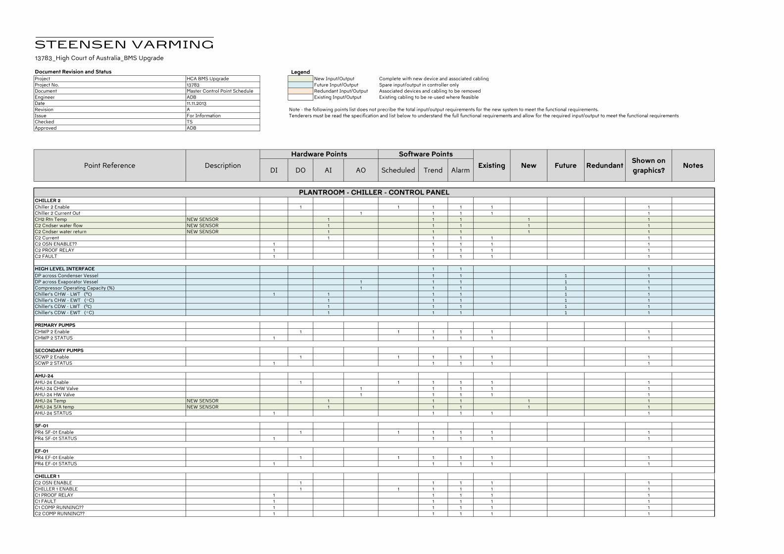
13783_High Court of Australia_BMS Upgrade
Document Revision and Status LegendProject HCA BMS Upgrade New Input/Output Complete with new device and associated cablingProject No. 13783 Future Input/Output Spare input/output in controller onlyDocument Master Control Point Schedule Redundant Input/Output Associated devices and cabling to be removedEngineer ADB Existing Input/Output Existing cabling to be re-used where feasibleDate 11.11.2013Revision A Note - the following points list does not precribe the total input/output requirements for the new system to meet the functional requirements.Issue For Information Tenderers must be read the specification and list below to understand the full functional requirements and allow for the required input/output to meet the functional requirementsChecked TSApproved ADB
DI DO AI AO Scheduled Trend Alarm
CHILLER 2
Chiller 2 Enable 1 1 1 1 1 1Chiller 2 Current Out 1 1 1 1 1CH2 Rtn Temp NEW SENSOR 1 1 1 1 1C2 Cndser water flow NEW SENSOR 1 1 1 1 1C2 Cndser water return NEW SENSOR 1 1 1 1 1C2 Current 1 1 1 1 1C2 OSN ENABLE?? 1 1 1 1 1C2 PROOF RELAY 1 1 1 1 1C2 FAULT 1 1 1 1 1
HIGH LEVEL INTERFACE 1 1 1
DP across Condenser Vessel 1 1 1 1
DP across Evaporator Vessel 1 1 1 1 1Compressor Operating Capacity (%) 1 1 1 1 1
Chiller's CHW - LWT (ᴼC) 1 1 1 1 1 1Chiller's CHW - EWT (ᴼC) 1 1 1 1 1
Chiller's CDW - LWT (ᴼC) 1 1 1 1 1Chiller's CDW - EWT (ᴼC) 1 1 1 1 1
PRIMARY PUMPS
CHWP 2 Enable 1 1 1 1 1 1CHWP 2 STATUS 1 1 1 1 1
SECONDARY PUMPS
SCWP 2 Enable 1 1 1 1 1 1SCWP 2 STATUS 1 1 1 1 1
AHU-24
AHU-24 Enable 1 1 1 1 1 1AHU-24 CHW Valve 1 1 1 1 1AHU-24 HW Valve 1 1 1 1 1AHU-24 Temp NEW SENSOR 1 1 1 1 1AHU-24 S/A temp NEW SENSOR 1 1 1 1 1AHU-24 STATUS 1 1 1 1 1
SF-01
PR4 SF-01 Enable 1 1 1 1 1 1PR4 SF-01 STATUS 1 1 1 1 1
EF-01
PR4 EF-01 Enable 1 1 1 1 1 1PR4 EF-01 STATUS 1 1 1 1 1
CHILLER 1
C2 OSN ENABLE 1 1 1 1 1CHILLER 1 ENABLE 1 1 1 1 1 1C1 PROOF RELAY 1 1 1 1 1C1 FAULT 1 1 1 1 1C1 COMP RUNNING?? 1 1 1 1 1C2 COMP RUNNING?? 1 1 1 1 1
PLANTROOM - CHILLER - CONTROL PANEL
Existing New RedundantShown on
graphics?NotesPoint Reference Description Future
Hardware Points Software Points
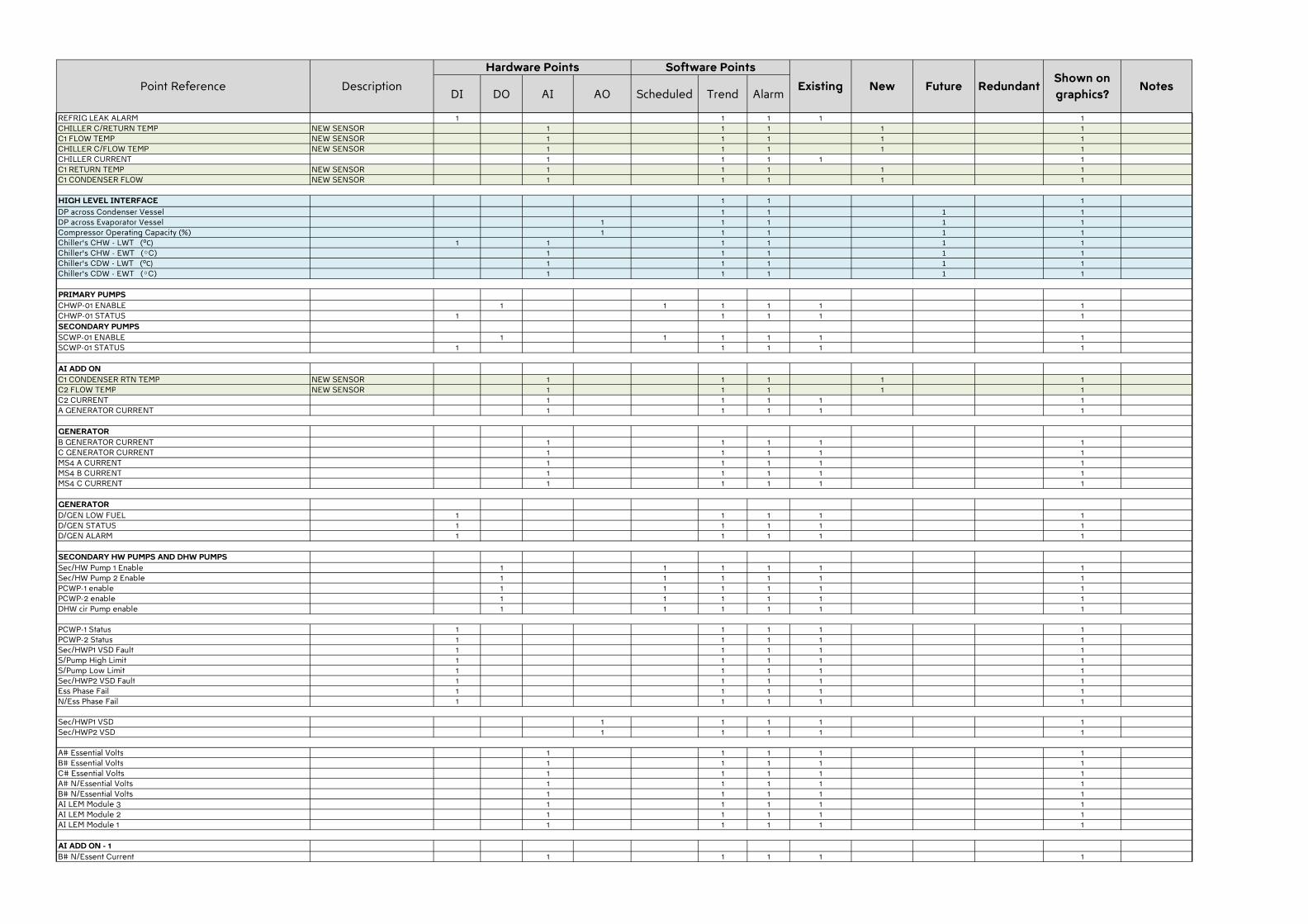
DI DO AI AO Scheduled Trend AlarmExisting New Redundant
Shown on
graphics?NotesPoint Reference Description Future
Hardware Points Software Points
REFRIG LEAK ALARM 1 1 1 1 1CHILLER C/RETURN TEMP NEW SENSOR 1 1 1 1 1C1 FLOW TEMP NEW SENSOR 1 1 1 1 1CHILLER C/FLOW TEMP NEW SENSOR 1 1 1 1 1CHILLER CURRENT 1 1 1 1 1C1 RETURN TEMP NEW SENSOR 1 1 1 1 1C1 CONDENSER FLOW NEW SENSOR 1 1 1 1 1
HIGH LEVEL INTERFACE 1 1 1
DP across Condenser Vessel 1 1 1 1DP across Evaporator Vessel 1 1 1 1 1Compressor Operating Capacity (%) 1 1 1 1 1Chiller's CHW - LWT (ᴼC) 1 1 1 1 1 1Chiller's CHW - EWT (ᴼC) 1 1 1 1 1Chiller's CDW - LWT (ᴼC) 1 1 1 1 1Chiller's CDW - EWT (ᴼC) 1 1 1 1 1
PRIMARY PUMPS
CHWP-01 ENABLE 1 1 1 1 1 1CHWP-01 STATUS 1 1 1 1 1
SECONDARY PUMPS
SCWP-01 ENABLE 1 1 1 1 1 1SCWP-01 STATUS 1 1 1 1 1
AI ADD ON
C1 CONDENSER RTN TEMP NEW SENSOR 1 1 1 1 1C2 FLOW TEMP NEW SENSOR 1 1 1 1 1C2 CURRENT 1 1 1 1 1A GENERATOR CURRENT 1 1 1 1 1
GENERATOR
B GENERATOR CURRENT 1 1 1 1 1C GENERATOR CURRENT 1 1 1 1 1MS4 A CURRENT 1 1 1 1 1MS4 B CURRENT 1 1 1 1 1MS4 C CURRENT 1 1 1 1 1
GENERATOR
D/GEN LOW FUEL 1 1 1 1 1D/GEN STATUS 1 1 1 1 1D/GEN ALARM 1 1 1 1 1
SECONDARY HW PUMPS AND DHW PUMPS
Sec/HW Pump 1 Enable 1 1 1 1 1 1Sec/HW Pump 2 Enable 1 1 1 1 1 1PCWP-1 enable 1 1 1 1 1 1PCWP-2 enable 1 1 1 1 1 1DHW cir Pump enable 1 1 1 1 1 1
PCWP-1 Status 1 1 1 1 1PCWP-2 Status 1 1 1 1 1Sec/HWP1 VSD Fault 1 1 1 1 1S/Pump High Limit 1 1 1 1 1S/Pump Low Limit 1 1 1 1 1Sec/HWP2 VSD Fault 1 1 1 1 1Ess Phase Fail 1 1 1 1 1N/Ess Phase Fail 1 1 1 1 1
Sec/HWP1 VSD 1 1 1 1 1Sec/HWP2 VSD 1 1 1 1 1
A# Essential Volts 1 1 1 1 1B# Essential Volts 1 1 1 1 1C# Essential Volts 1 1 1 1 1A# N/Essential Volts 1 1 1 1 1B# N/Essential Volts 1 1 1 1 1AI LEM Module 3 1 1 1 1 1AI LEM Module 2 1 1 1 1 1AI LEM Module 1 1 1 1 1 1
AI ADD ON - 1
B# N/Essent Current 1 1 1 1 1
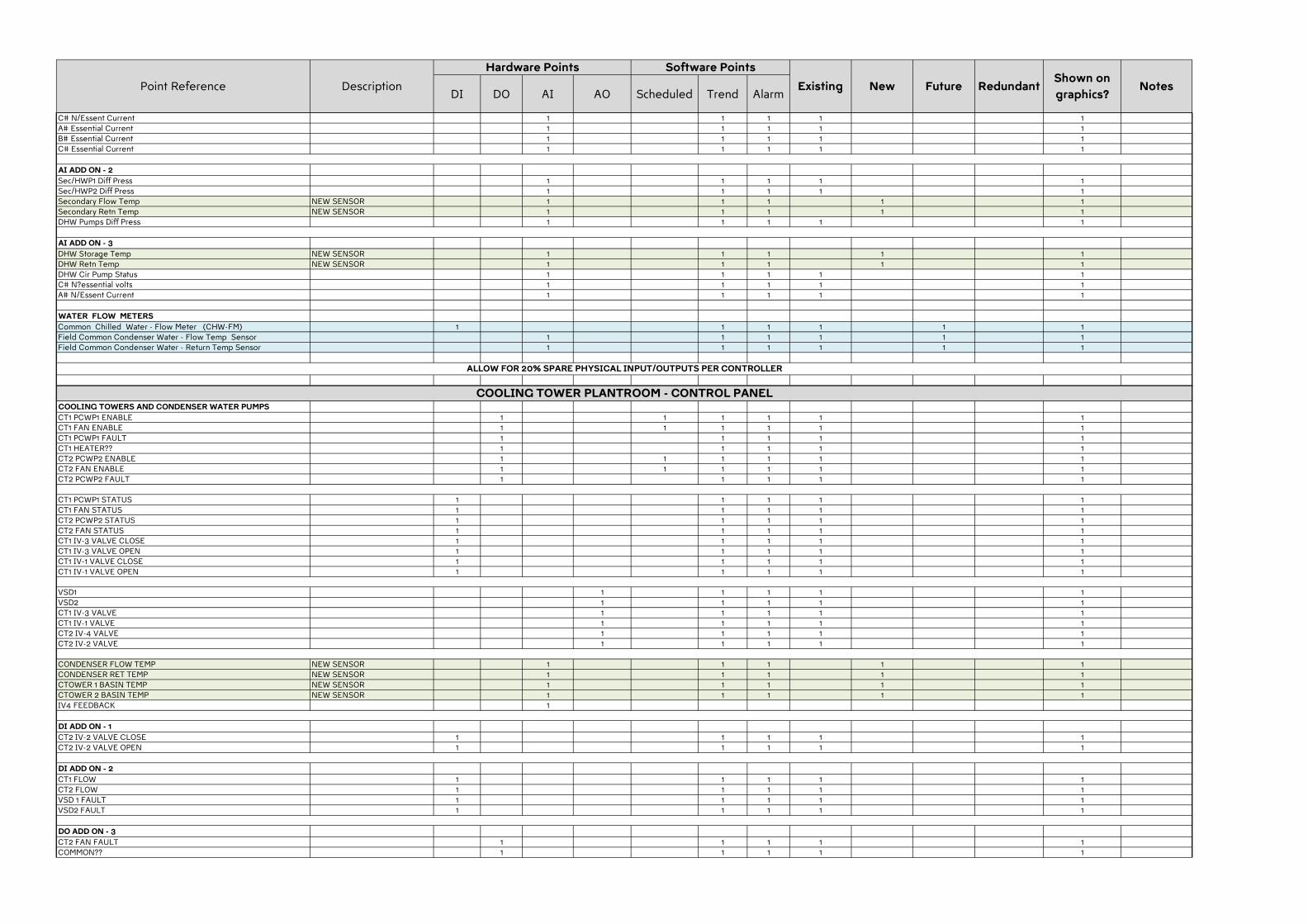
DI DO AI AO Scheduled Trend AlarmExisting New Redundant
Shown on
graphics?NotesPoint Reference Description Future
Hardware Points Software Points
C# N/Essent Current 1 1 1 1 1A# Essential Current 1 1 1 1 1B# Essential Current 1 1 1 1 1C# Essential Current 1 1 1 1 1
AI ADD ON - 2
Sec/HWP1 Diff Press 1 1 1 1 1Sec/HWP2 Diff Press 1 1 1 1 1Secondary Flow Temp NEW SENSOR 1 1 1 1 1Secondary Retn Temp NEW SENSOR 1 1 1 1 1DHW Pumps Diff Press 1 1 1 1 1
AI ADD ON - 3
DHW Storage Temp NEW SENSOR 1 1 1 1 1DHW Retn Temp NEW SENSOR 1 1 1 1 1DHW Cir Pump Status 1 1 1 1 1C# N?essential volts 1 1 1 1 1A# N/Essent Current 1 1 1 1 1
WATER FLOW METERS
Common Chilled Water - Flow Meter (CHW-FM) 1 1 1 1 1 1Field Common Condenser Water - Flow Temp Sensor 1 1 1 1 1 1Field Common Condenser Water - Return Temp Sensor 1 1 1 1 1 1
COOLING TOWERS AND CONDENSER WATER PUMPS
CT1 PCWP1 ENABLE 1 1 1 1 1 1CT1 FAN ENABLE 1 1 1 1 1 1CT1 PCWP1 FAULT 1 1 1 1 1CT1 HEATER?? 1 1 1 1 1CT2 PCWP2 ENABLE 1 1 1 1 1 1CT2 FAN ENABLE 1 1 1 1 1 1CT2 PCWP2 FAULT 1 1 1 1 1
CT1 PCWP1 STATUS 1 1 1 1 1CT1 FAN STATUS 1 1 1 1 1CT2 PCWP2 STATUS 1 1 1 1 1CT2 FAN STATUS 1 1 1 1 1CT1 IV-3 VALVE CLOSE 1 1 1 1 1CT1 IV-3 VALVE OPEN 1 1 1 1 1CT1 IV-1 VALVE CLOSE 1 1 1 1 1CT1 IV-1 VALVE OPEN 1 1 1 1 1
VSD1 1 1 1 1 1VSD2 1 1 1 1 1CT1 IV-3 VALVE 1 1 1 1 1CT1 IV-1 VALVE 1 1 1 1 1CT2 IV-4 VALVE 1 1 1 1 1CT2 IV-2 VALVE 1 1 1 1 1
CONDENSER FLOW TEMP NEW SENSOR 1 1 1 1 1CONDENSER RET TEMP NEW SENSOR 1 1 1 1 1CTOWER 1 BASIN TEMP NEW SENSOR 1 1 1 1 1CTOWER 2 BASIN TEMP NEW SENSOR 1 1 1 1 1IV4 FEEDBACK 1
DI ADD ON - 1
CT2 IV-2 VALVE CLOSE 1 1 1 1 1CT2 IV-2 VALVE OPEN 1 1 1 1 1
DI ADD ON - 2
CT1 FLOW 1 1 1 1 1CT2 FLOW 1 1 1 1 1VSD 1 FAULT 1 1 1 1 1VSD2 FAULT 1 1 1 1 1
DO ADD ON - 3
CT2 FAN FAULT 1 1 1 1 1COMMON?? 1 1 1 1 1
ALLOW FOR 20% SPARE PHYSICAL INPUT/OUTPUTS PER CONTROLLER
COOLING TOWER PLANTROOM - CONTROL PANEL
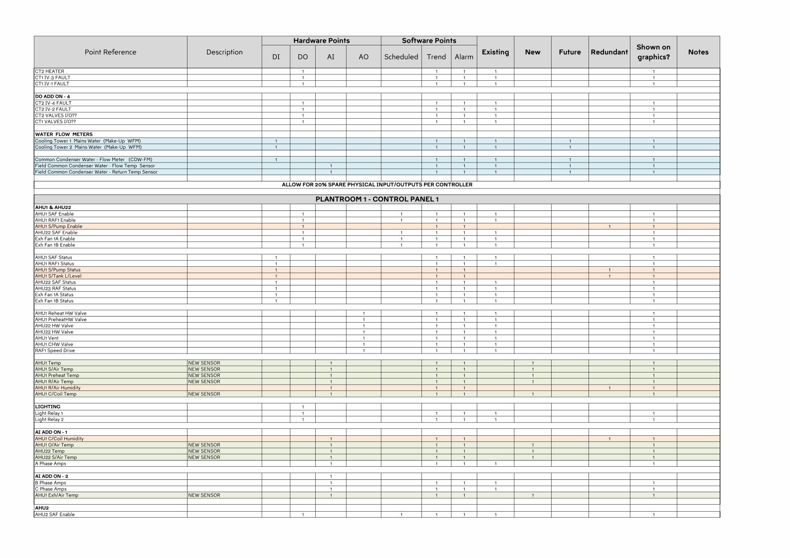
DI DO AI AO Scheduled Trend AlarmExisting New Redundant
Shown on
graphics?NotesPoint Reference Description Future
Hardware Points Software Points
CT2 HEATER 1 1 1 1 1CT1 IV-3 FAULT 1 1 1 1 1CT1 IV-1 FAULT 1 1 1 1 1
DO ADD ON - 4
CT2 IV-4 FAULT 1 1 1 1 1CT2 IV-2 FAULT 1 1 1 1 1CT2 VALVES I/O?? 1 1 1 1 1CT1 VALVES I/O?? 1 1 1 1 1
WATER FLOW METERS
Cooling Tower 1 Mains Water (Make-Up WFM) 1 1 1 1 1 1Cooling Tower 2 Mains Water (Make-Up WFM) 1 1 1 1 1 1
Common Condenser Water - Flow Meter (CDW-FM) 1 1 1 1 1 1Field Common Condenser Water - Flow Temp Sensor 1 1 1 1 1 1Field Common Condenser Water - Return Temp Sensor 1 1 1 1 1 1
AHU1 & AHU22
AHU1 SAF Enable 1 1 1 1 1 1AHU1 RAF1 Enable 1 1 1 1 1 1AHU1 S/Pump Enable 1 1 1 1 1AHU22 SAF Enable 1 1 1 1 1 1Exh Fan 1A Enable 1 1 1 1 1 1Exh Fan 1B Enable 1 1 1 1 1 1
AHU1 SAF Status 1 1 1 1 1AHU1 RAF1 Status 1 1 1 1 1AHU1 S/Pump Status 1 1 1 1 1AHU1 S/Tank L/Level 1 1 1 1 1AHU22 SAF Status 1 1 1 1 1AHU23 RAF Status 1 1 1 1 1Exh Fan 1A Status 1 1 1 1 1Exh Fan 1B Status 1 1 1 1 1
AHU1 Reheat HW Valve 1 1 1 1 1AHU1 PreheatHW Valve 1 1 1 1 1AHU22 HW Valve 1 1 1 1 1AHU22 HW Valve 1 1 1 1 1AHU1 Vent 1 1 1 1 1AHU1 CHW Valve 1 1 1 1 1RAF1 Speed Drive 1 1 1 1 1
AHU1 Temp NEW SENSOR 1 1 1 1 1AHU1 S/Air Temp NEW SENSOR 1 1 1 1 1AHU1 Preheat Temp NEW SENSOR 1 1 1 1 1AHU1 R/Air Temp NEW SENSOR 1 1 1 1 1AHU1 R/Air Humidity 1 1 1 1 1AHU1 C/Coil Temp NEW SENSOR 1 1 1 1 1
LIGHTING 1
Light Relay 1 1 1 1 1 1Light Relay 2 1 1 1 1 1
AI ADD ON - 1
AHU1 C/Coil Humidity 1 1 1 1 1AHU1 O/Air Temp NEW SENSOR 1 1 1 1 1AHU22 Temp NEW SENSOR 1 1 1 1 1AHU22 S/Air Temp NEW SENSOR 1 1 1 1 1A Phase Amps 1 1 1 1 1
AI ADD ON - 2 1
B Phase Amps 1 1 1 1 1C Phase Amps 1 1 1 1 1AHU1 Exh/Air Temp NEW SENSOR 1 1 1 1 1
AHU2
AHU2 SAF Enable 1 1 1 1 1 1
ALLOW FOR 20% SPARE PHYSICAL INPUT/OUTPUTS PER CONTROLLER
PLANTROOM 1 - CONTROL PANEL 1
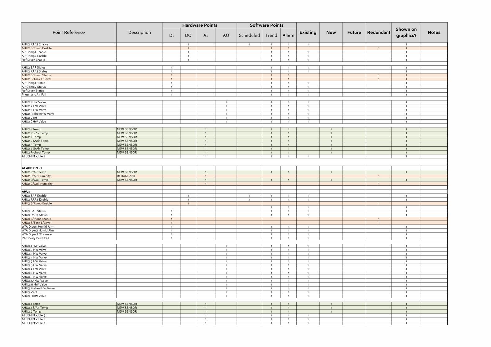
DI DO AI AO Scheduled Trend AlarmExisting New Redundant
Shown on
graphics?NotesPoint Reference Description Future
Hardware Points Software Points
AHU2 RAF2 Enable 1 1 1 1 1 1AHU2 S/Pump Enable 1 1 1 1 1Air Comp1 Enable 1 1 1 1 1Air Comp2 Enable 1 1 1 1 1Ref Dryer Enable 1 1 1 1 1
AHU2 SAF Status 1 1 1 1 1AHU2 RAF2 Status 1 1 1 1 1AHU2 S/Pump Status 1 1 1 1 1AHU2 S/Tank L/Level 1 1 1 1 1Air Comp1 Status 1 1 1 1 1Air Comp2 Status 1 1 1 1 1Ref Dryer Status 1 1 1 1 1Pneumatic Air Fail 1 1 1 1 1
AHU2.1 HW Valve 1 1 1 1 1AHU2.2 HW Valve 1 1 1 1 1AHU2.3 HW Valve 1 1 1 1 1AHU2 PreheatHW Valve 1 1 1 1 1AHU2 Vent 1 1 1 1 1AHU2 CHW Valve 1 1 1 1 1
AHU2.1 Temp NEW SENSOR 1 1 1 1 1AHU2.1 S/Air Temp NEW SENSOR 1 1 1 1 1AHU2.2 Temp NEW SENSOR 1 1 1 1 1AHU2.2 S/Air Temp NEW SENSOR 1 1 1 1 1AHU2.3 Temp NEW SENSOR 1 1 1 1 1AHU2.3 S/Air Temp NEW SENSOR 1 1 1 1 1AHU2 Preheat Temp NEW SENSOR 1 1 1 1 1AI LEM Module 1 1 1 1 1 1
AI ADD ON - 1
AHU2 R/Air Temp NEW SENSOR 1 1 1 1 1AHU2 R/Air Humidity REDUNDANT 1 1AHU2 C/Coil Temp NEW SENSOR 1 1 1 1 1AHU2 C/Coil Humidity 1 1
AHU3
AHU3 SAF Enable 1 1 1 1 1 1AHU3 RAF3 Enable 1 1 1 1 1 1AHU3 S/Pump Enable 1 1
1 1 1 1AHU3 SAF Status 1 1 1 1 1AHU3 RAF3 Status 1 1 1 1 1AHU3 S/Pump Status 1 1AHU3 S/Tank L/Level 1 1W/A Dryer1 Humid Alm 1 1 1 1 1W/A Dryer2 Humid Alm 1 1 1 1 1W/A Dryer L/Pressure 1 1 1 1 1RAF1 Vary Drive Fail 1 1 1 1 1
AHU3.1 HW Valve 1 1 1 1 1AHU3.2 HW Valve 1 1 1 1 1AHU3.3 HW Valve 1 1 1 1 1AHU3.4 HW Valve 1 1 1 1 1AHU3.5 HW Valve 1 1 1 1 1AHU3.6 HW Valve 1 1 1 1 1AHU3.7 HW Valve 1 1 1 1 1AHU3.8 HW Valve 1 1 1 1 1AHU3.9 HW Valve 1 1 1 1 1AHU3.10 HW Valve 1 1 1 1 1AHU3.11 HW Valve 1 1 1 1 1AHU3 PreheatHW Valve 1 1 1 1 1AHU3 Vent 1 1 1 1 1AHU3 CHW Valve 1 1 1 1 1
AHU3.1 Temp NEW SENSOR 1 1 1 1 1AHU3.1 S/Air Temp NEW SENSOR 1 1 1 1 1AHU3.2 Temp NEW SENSOR 1 1 1 1 1AI LEM Module 5 1 1 1 1 1AI LEM Module 4 1 1 1 1 1AI LEM Module 3 1 1 1 1 1
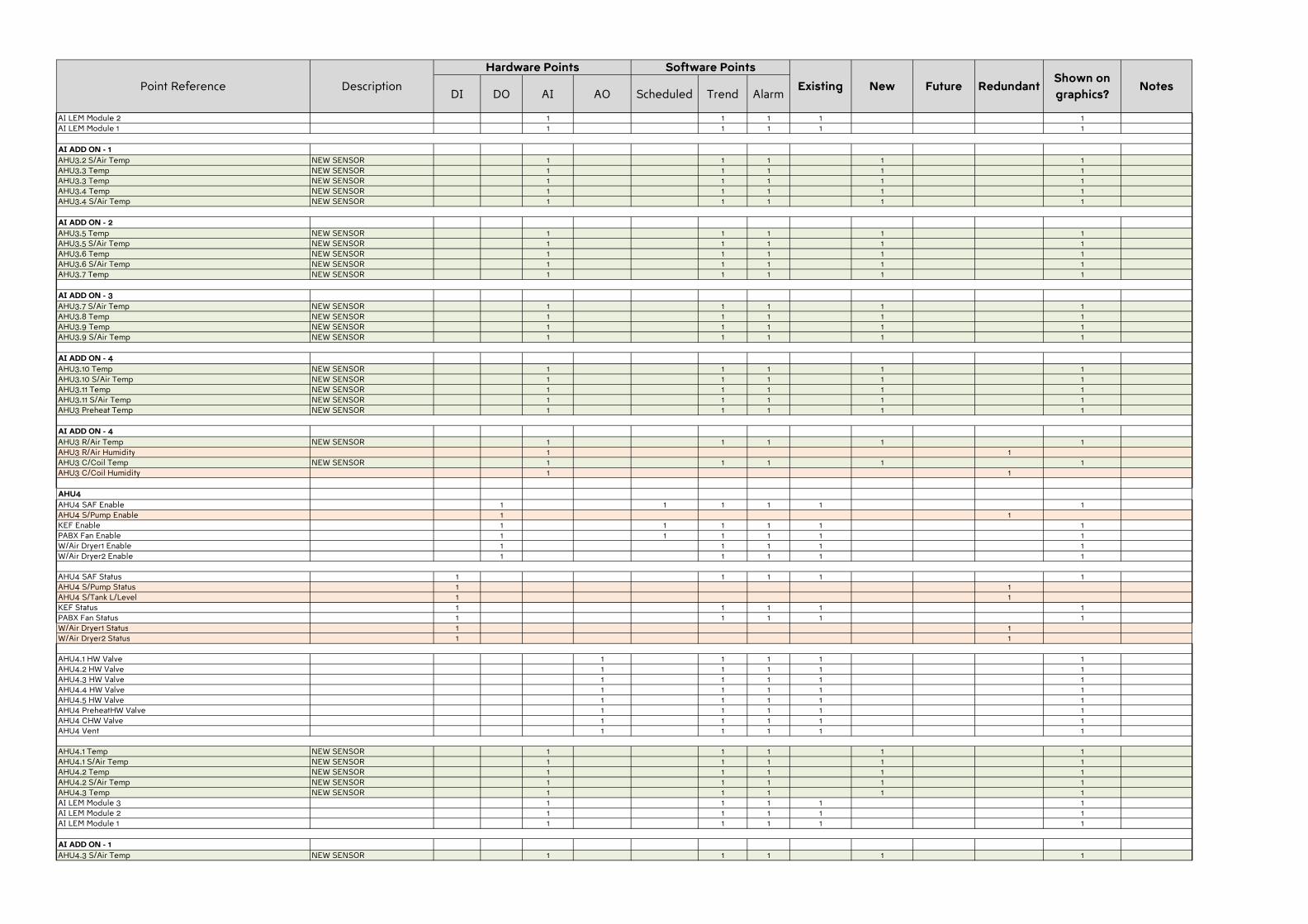
DI DO AI AO Scheduled Trend AlarmExisting New Redundant
Shown on
graphics?NotesPoint Reference Description Future
Hardware Points Software Points
AI LEM Module 2 1 1 1 1 1AI LEM Module 1 1 1 1 1 1
AI ADD ON - 1
AHU3.2 S/Air Temp NEW SENSOR 1 1 1 1 1AHU3.3 Temp NEW SENSOR 1 1 1 1 1AHU3.3 Temp NEW SENSOR 1 1 1 1 1AHU3.4 Temp NEW SENSOR 1 1 1 1 1AHU3.4 S/Air Temp NEW SENSOR 1 1 1 1 1
AI ADD ON - 2
AHU3.5 Temp NEW SENSOR 1 1 1 1 1AHU3.5 S/Air Temp NEW SENSOR 1 1 1 1 1AHU3.6 Temp NEW SENSOR 1 1 1 1 1AHU3.6 S/Air Temp NEW SENSOR 1 1 1 1 1AHU3.7 Temp NEW SENSOR 1 1 1 1 1
AI ADD ON - 3
AHU3.7 S/Air Temp NEW SENSOR 1 1 1 1 1AHU3.8 Temp NEW SENSOR 1 1 1 1 1AHU3.9 Temp NEW SENSOR 1 1 1 1 1AHU3.9 S/Air Temp NEW SENSOR 1 1 1 1 1
AI ADD ON - 4
AHU3.10 Temp NEW SENSOR 1 1 1 1 1AHU3.10 S/Air Temp NEW SENSOR 1 1 1 1 1AHU3.11 Temp NEW SENSOR 1 1 1 1 1AHU3.11 S/Air Temp NEW SENSOR 1 1 1 1 1AHU3 Preheat Temp NEW SENSOR 1 1 1 1 1
AI ADD ON - 4
AHU3 R/Air Temp NEW SENSOR 1 1 1 1 1AHU3 R/Air Humidity 1 1AHU3 C/Coil Temp NEW SENSOR 1 1 1 1 1AHU3 C/Coil Humidity 1 1
AHU4
AHU4 SAF Enable 1 1 1 1 1 1AHU4 S/Pump Enable 1 1KEF Enable 1 1 1 1 1 1PABX Fan Enable 1 1 1 1 1 1W/Air Dryer1 Enable 1 1 1 1 1W/Air Dryer2 Enable 1 1 1 1 1
AHU4 SAF Status 1 1 1 1 1AHU4 S/Pump Status 1 1AHU4 S/Tank L/Level 1 1KEF Status 1 1 1 1 1PABX Fan Status 1 1 1 1 1W/Air Dryer1 Status 1 1W/Air Dryer2 Status 1 1
AHU4.1 HW Valve 1 1 1 1 1AHU4.2 HW Valve 1 1 1 1 1AHU4.3 HW Valve 1 1 1 1 1AHU4.4 HW Valve 1 1 1 1 1AHU4.5 HW Valve 1 1 1 1 1AHU4 PreheatHW Valve 1 1 1 1 1AHU4 CHW Valve 1 1 1 1 1AHU4 Vent 1 1 1 1 1
AHU4.1 Temp NEW SENSOR 1 1 1 1 1AHU4.1 S/Air Temp NEW SENSOR 1 1 1 1 1AHU4.2 Temp NEW SENSOR 1 1 1 1 1AHU4.2 S/Air Temp NEW SENSOR 1 1 1 1 1AHU4.3 Temp NEW SENSOR 1 1 1 1 1AI LEM Module 3 1 1 1 1 1AI LEM Module 2 1 1 1 1 1AI LEM Module 1 1 1 1 1 1
AI ADD ON - 1
AHU4.3 S/Air Temp NEW SENSOR 1 1 1 1 1
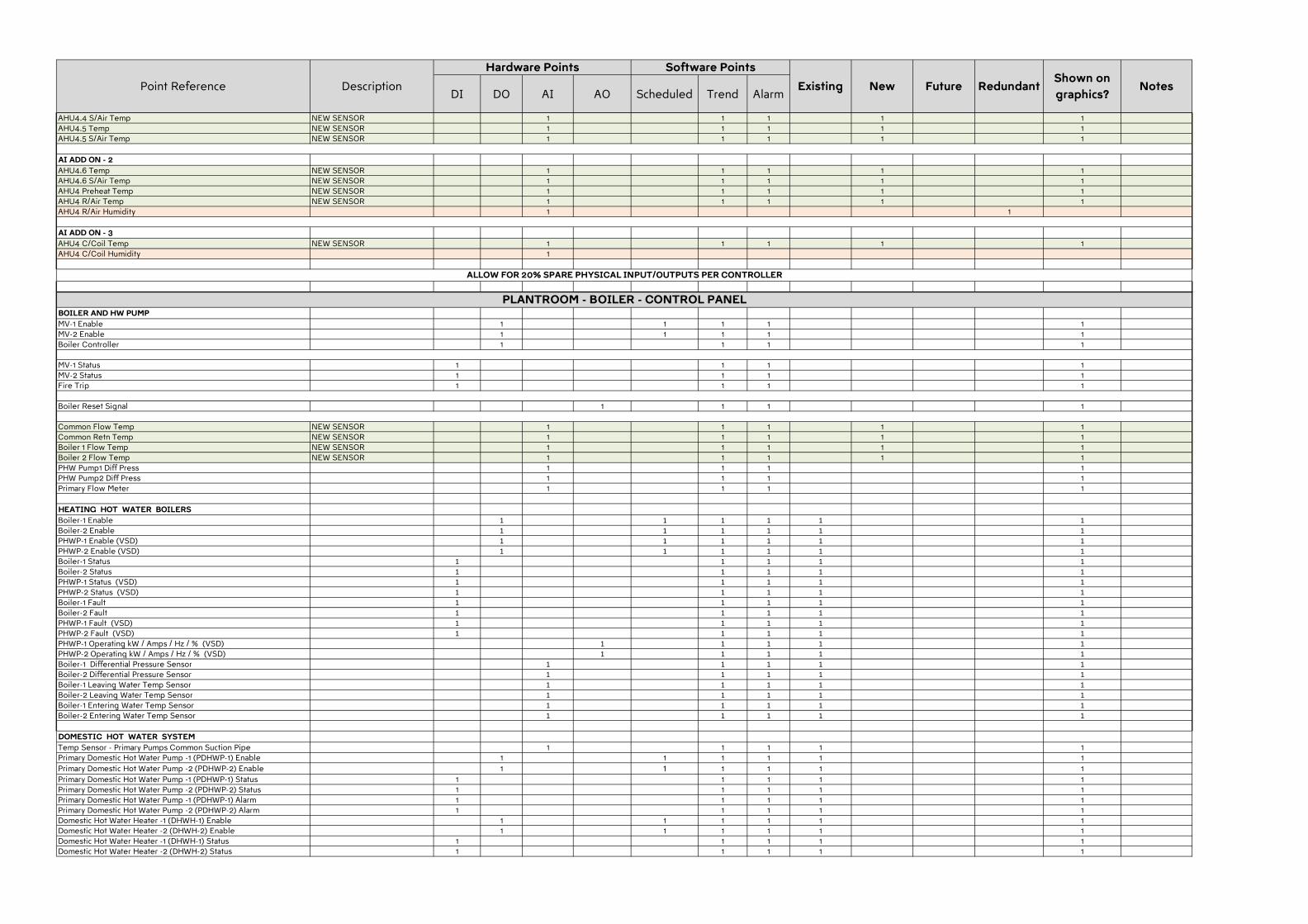
DI DO AI AO Scheduled Trend AlarmExisting New Redundant
Shown on
graphics?NotesPoint Reference Description Future
Hardware Points Software Points
AHU4.4 S/Air Temp NEW SENSOR 1 1 1 1 1AHU4.5 Temp NEW SENSOR 1 1 1 1 1AHU4.5 S/Air Temp NEW SENSOR 1 1 1 1 1
AI ADD ON - 2
AHU4.6 Temp NEW SENSOR 1 1 1 1 1AHU4.6 S/Air Temp NEW SENSOR 1 1 1 1 1AHU4 Preheat Temp NEW SENSOR 1 1 1 1 1AHU4 R/Air Temp NEW SENSOR 1 1 1 1 1AHU4 R/Air Humidity 1 1
AI ADD ON - 3
AHU4 C/Coil Temp NEW SENSOR 1 1 1 1 1AHU4 C/Coil Humidity 1
BOILER AND HW PUMP
MV-1 Enable 1 1 1 1 1MV-2 Enable 1 1 1 1 1Boiler Controller 1 1 1 1
MV-1 Status 1 1 1 1MV-2 Status 1 1 1 1Fire Trip 1 1 1 1
Boiler Reset Signal 1 1 1 1
Common Flow Temp NEW SENSOR 1 1 1 1 1Common Retn Temp NEW SENSOR 1 1 1 1 1Boiler 1 Flow Temp NEW SENSOR 1 1 1 1 1Boiler 2 Flow Temp NEW SENSOR 1 1 1 1 1PHW Pump1 Diff Press 1 1 1 1PHW Pump2 Diff Press 1 1 1 1Primary Flow Meter 1 1 1 1
HEATING HOT WATER BOILERS
Boiler-1 Enable 1 1 1 1 1 1
Boiler-2 Enable 1 1 1 1 1 1
PHWP-1 Enable (VSD) 1 1 1 1 1 1
PHWP-2 Enable (VSD) 1 1 1 1 1 1
Boiler-1 Status 1 1 1 1 1
Boiler-2 Status 1 1 1 1 1
PHWP-1 Status (VSD) 1 1 1 1 1
PHWP-2 Status (VSD) 1 1 1 1 1
Boiler-1 Fault 1 1 1 1 1
Boiler-2 Fault 1 1 1 1 1
PHWP-1 Fault (VSD) 1 1 1 1 1
PHWP-2 Fault (VSD) 1 1 1 1 1
PHWP-1 Operating kW / Amps / Hz / % (VSD) 1 1 1 1 1
PHWP-2 Operating kW / Amps / Hz / % (VSD) 1 1 1 1 1
Boiler-1 Differential Pressure Sensor 1 1 1 1 1
Boiler-2 Differential Pressure Sensor 1 1 1 1 1
Boiler-1 Leaving Water Temp Sensor 1 1 1 1 1
Boiler-2 Leaving Water Temp Sensor 1 1 1 1 1
Boiler-1 Entering Water Temp Sensor 1 1 1 1 1
Boiler-2 Entering Water Temp Sensor 1 1 1 1 1
DOMESTIC HOT WATER SYSTEM
Temp Sensor - Primary Pumps Common Suction Pipe 1 1 1 1 1Primary Domestic Hot Water Pump -1 (PDHWP-1) Enable 1 1 1 1 1 1
Primary Domestic Hot Water Pump -2 (PDHWP-2) Enable 1 1 1 1 1 1
Primary Domestic Hot Water Pump -1 (PDHWP-1) Status 1 1 1 1 1Primary Domestic Hot Water Pump -2 (PDHWP-2) Status 1 1 1 1 1Primary Domestic Hot Water Pump -1 (PDHWP-1) Alarm 1 1 1 1 1Primary Domestic Hot Water Pump -2 (PDHWP-2) Alarm 1 1 1 1 1Domestic Hot Water Heater -1 (DHWH-1) Enable 1 1 1 1 1 1Domestic Hot Water Heater -2 (DHWH-2) Enable 1 1 1 1 1 1Domestic Hot Water Heater -1 (DHWH-1) Status 1 1 1 1 1Domestic Hot Water Heater -2 (DHWH-2) Status 1 1 1 1 1
ALLOW FOR 20% SPARE PHYSICAL INPUT/OUTPUTS PER CONTROLLER
PLANTROOM - BOILER - CONTROL PANEL
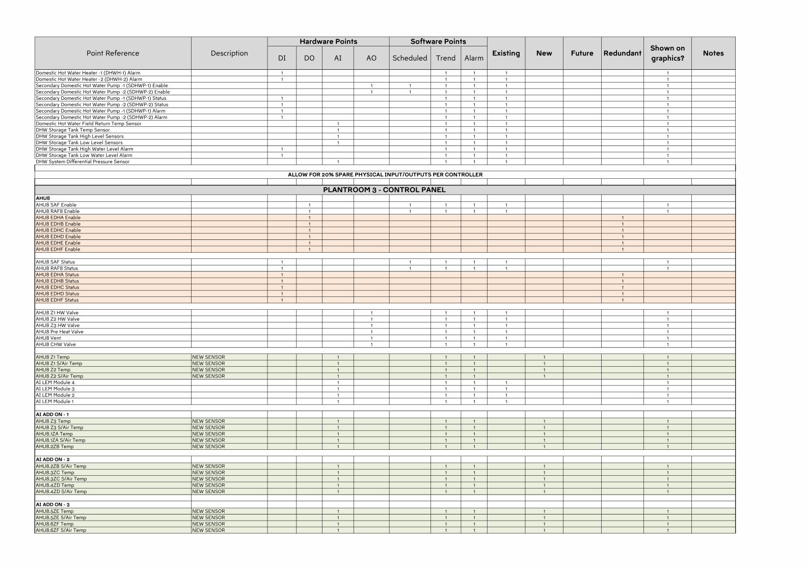
DI DO AI AO Scheduled Trend AlarmExisting New Redundant
Shown on
graphics?NotesPoint Reference Description Future
Hardware Points Software Points
Domestic Hot Water Heater -1 (DHWH-1) Alarm 1 1 1 1 1Domestic Hot Water Heater -2 (DHWH-2) Alarm 1 1 1 1 1Secondary Domestic Hot Water Pump -1 (SDHWP-1) Enable 1 1 1 1 1 1Secondary Domestic Hot Water Pump -2 (SDHWP-2) Enable 1 1 1 1 1 1Secondary Domestic Hot Water Pump -1 (SDHWP-1) Status 1 1 1 1 1Secondary Domestic Hot Water Pump -2 (SDHWP-2) Status 1 1 1 1 1Secondary Domestic Hot Water Pump -1 (SDHWP-1) Alarm 1 1 1 1 1Secondary Domestic Hot Water Pump -2 (SDHWP-2) Alarm 1 1 1 1 1Domestic Hot Water Field Return Temp Sensor 1 1 1 1 1DHW Storage Tank Temp Sensor 1 1 1 1 1DHW Storage Tank High Level Sensors 1 1 1 1 1DHW Storage Tank Low Level Sensors 1 1 1 1 1DHW Storage Tank High Water Level Alarm 1 1 1 1 1DHW Storage Tank Low Water Level Alarm 1 1 1 1 1DHW System Differential Pressure Sensor 1 1 1 1 1
AHU8
AHU8 SAF Enable 1 1 1 1 1 1AHU8 RAF8 Enable 1 1 1 1 1 1AHU8 EDHA Enable 1 1AHU8 EDHB Enable 1 1AHU8 EDHC Enable 1 1AHU8 EDHD Enable 1 1AHU8 EDHE Enable 1 1AHU8 EDHF Enable 1 1
AHU8 SAF Status 1 1 1 1 1 1AHU8 RAF8 Status 1 1 1 1 1 1AHU8 EDHA Status 1 1AHU8 EDHB Status 1 1AHU8 EDHC Status 1 1AHU8 EDHD Status 1 1AHU8 EDHF Status 1 1
AHU8 Z1 HW Valve 1 1 1 1 1AHU8 Z2 HW Valve 1 1 1 1 1AHU8 Z3 HW Valve 1 1 1 1 1AHU8 Pre Heat Valve 1 1 1 1 1AHU8 Vent 1 1 1 1 1AHU8 CHW Valve 1 1 1 1 1
AHU8 Z1 Temp NEW SENSOR 1 1 1 1 1AHU8 Z1 S/Air Temp NEW SENSOR 1 1 1 1 1AHU8 Z2 Temp NEW SENSOR 1 1 1 1 1AHU8 Z2 S/Air Temp NEW SENSOR 1 1 1 1 1AI LEM Module 4 1 1 1 1 1AI LEM Module 3 1 1 1 1 1AI LEM Module 2 1 1 1 1 1AI LEM Module 1 1 1 1 1 1
AI ADD ON - 1
AHU8 Z3 Temp NEW SENSOR 1 1 1 1 1AHU8 Z3 S/Air Temp NEW SENSOR 1 1 1 1 1AHU8.1ZA Temp NEW SENSOR 1 1 1 1 1AHU8.1ZA S/Air Temp NEW SENSOR 1 1 1 1 1AHU8.2ZB Temp NEW SENSOR 1 1 1 1 1
AI ADD ON - 2
AHU8.2ZB S/Air Temp NEW SENSOR 1 1 1 1 1AHU8.3ZC Temp NEW SENSOR 1 1 1 1 1AHU8.3ZC S/Air Temp NEW SENSOR 1 1 1 1 1AHU8.4ZD Temp NEW SENSOR 1 1 1 1 1AHU8.4ZD S/Air Temp NEW SENSOR 1 1 1 1 1
AI ADD ON - 3
AHU8.5ZE Temp NEW SENSOR 1 1 1 1 1AHU8.5ZE S/Air Temp NEW SENSOR 1 1 1 1 1AHU8.6ZF Temp NEW SENSOR 1 1 1 1 1AHU8.6ZF S/Air Temp NEW SENSOR 1 1 1 1 1
ALLOW FOR 20% SPARE PHYSICAL INPUT/OUTPUTS PER CONTROLLER
PLANTROOM 3 - CONTROL PANEL
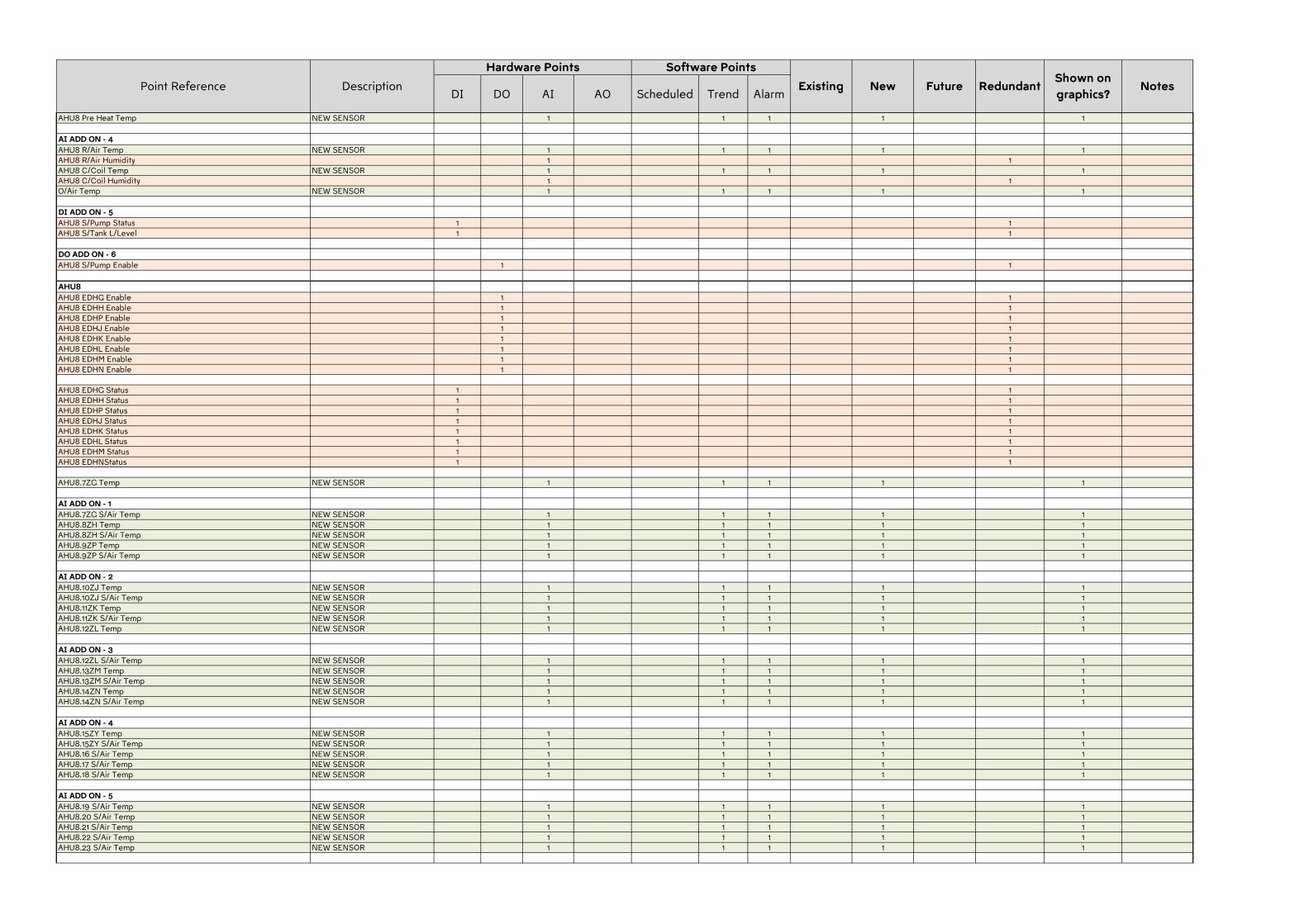
DI DO AI AO Scheduled Trend AlarmExisting New Redundant
Shown on
graphics?NotesPoint Reference Description Future
Hardware Points Software Points
AHU8 Pre Heat Temp NEW SENSOR 1 1 1 1 1
AI ADD ON - 4
AHU8 R/Air Temp NEW SENSOR 1 1 1 1 1AHU8 R/Air Humidity 1 1AHU8 C/Coil Temp NEW SENSOR 1 1 1 1 1AHU8 C/Coil Humidity 1 1O/Air Temp NEW SENSOR 1 1 1 1 1
DI ADD ON - 5
AHU8 S/Pump Status 1 1AHU8 S/Tank L/Level 1 1
DO ADD ON - 6
AHU8 S/Pump Enable 1 1
AHU8
AHU8 EDHG Enable 1 1AHU8 EDHH Enable 1 1AHU8 EDHP Enable 1 1AHU8 EDHJ Enable 1 1AHU8 EDHK Enable 1 1AHU8 EDHL Enable 1 1AHU8 EDHM Enable 1 1AHU8 EDHN Enable 1 1
AHU8 EDHG Status 1 1AHU8 EDHH Status 1 1AHU8 EDHP Status 1 1AHU8 EDHJ Status 1 1AHU8 EDHK Status 1 1AHU8 EDHL Status 1 1AHU8 EDHM Status 1 1AHU8 EDHNStatus 1 1
AHU8.7ZG Temp NEW SENSOR 1 1 1 1 1
AI ADD ON - 1
AHU8.7ZG S/Air Temp NEW SENSOR 1 1 1 1 1AHU8.8ZH Temp NEW SENSOR 1 1 1 1 1AHU8.8ZH S/Air Temp NEW SENSOR 1 1 1 1 1AHU8.9ZP Temp NEW SENSOR 1 1 1 1 1AHU8.9ZP S/Air Temp NEW SENSOR 1 1 1 1 1
AI ADD ON - 2
AHU8.10ZJ Temp NEW SENSOR 1 1 1 1 1AHU8.10ZJ S/Air Temp NEW SENSOR 1 1 1 1 1AHU8.11ZK Temp NEW SENSOR 1 1 1 1 1AHU8.11ZK S/Air Temp NEW SENSOR 1 1 1 1 1AHU8.12ZL Temp NEW SENSOR 1 1 1 1 1
AI ADD ON - 3
AHU8.12ZL S/Air Temp NEW SENSOR 1 1 1 1 1AHU8.13ZM Temp NEW SENSOR 1 1 1 1 1AHU8.13ZM S/Air Temp NEW SENSOR 1 1 1 1 1AHU8.14ZN Temp NEW SENSOR 1 1 1 1 1AHU8.14ZN S/Air Temp NEW SENSOR 1 1 1 1 1
AI ADD ON - 4
AHU8.15ZY Temp NEW SENSOR 1 1 1 1 1AHU8.15ZY S/Air Temp NEW SENSOR 1 1 1 1 1AHU8.16 S/Air Temp NEW SENSOR 1 1 1 1 1AHU8.17 S/Air Temp NEW SENSOR 1 1 1 1 1AHU8.18 S/Air Temp NEW SENSOR 1 1 1 1 1
AI ADD ON - 5
AHU8.19 S/Air Temp NEW SENSOR 1 1 1 1 1AHU8.20 S/Air Temp NEW SENSOR 1 1 1 1 1AHU8.21 S/Air Temp NEW SENSOR 1 1 1 1 1AHU8.22 S/Air Temp NEW SENSOR 1 1 1 1 1AHU8.23 S/Air Temp NEW SENSOR 1 1 1 1 1
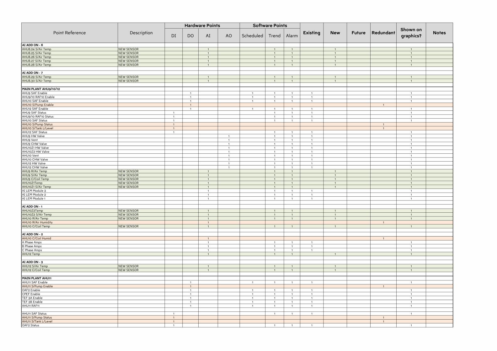
DI DO AI AO Scheduled Trend AlarmExisting New Redundant
Shown on
graphics?NotesPoint Reference Description Future
Hardware Points Software Points
AI ADD ON - 6
AHU8.24 S/Air Temp NEW SENSOR 1 1 1 1 1AHU8.25 S/Air Temp NEW SENSOR 1 1 1 1 1AHU8.26 S/Air Temp NEW SENSOR 1 1 1 1 1AHU8.27 S/Air Temp NEW SENSOR 1 1 1 1 1AHU8.28 S/Air Temp NEW SENSOR 1 1 1 1 1
AI ADD ON - 7
AHU8.29 S/Air Temp NEW SENSOR 1 1 1 1 1AHU8.30 S/Air Temp NEW SENSOR 1 1 1 1 1
MAIN PLANT AHU9/10/12
AHU9 SAF Enable 1 1 1 1 1 1AHU9/10 RAF10 Enable 1 1 1 1 1 1AHU10 SAF Enable 1 1 1 1 1 1AHU10 S/Pump Enable 1 1AHU12 SAF Enable 1 1 1 1 1 1AHU9 SAF Status 1 1 1 1 1AHU9/10 RAF10 Status 1 1 1 1 1AHU10 SAF Status 1 1 1 1 1AHU10 S/Pump Status 1 1AHU10 S/Tank L/Level 1 1AHU12 SAF Status 1 1 1 1 1AHU9 HW Valve 1 1 1 1 1AHU9 Vent 1 1 1 1 1AHU9 CHW Valve 1 1 1 1 1AHU10Z1 HW Valve 1 1 1 1 1AHU10Z2 HW Valve 1 1 1 1 1AHU10 Vent 1 1 1 1 1AHU10 CHW Valve 1 1 1 1 1AHU12 HW Valve 1 1 1 1 1AHU12 CHW Valve 1 1 1 1 1AHU9 R/Air Temp NEW SENSOR 1 1 1 1 1AHU9 S/Air Temp NEW SENSOR 1 1 1 1 1AHU9 C/Coil Temp NEW SENSOR 1 1 1 1 1AHU10Z1Temp NEW SENSOR 1 1 1 1 1AHU10Z1 S/Air Temp NEW SENSOR 1 1 1 1 1AI LEM Module 3 1 1 1 1 1AI LEM Module 2 1 1 1 1 1AI LEM Module 1 1 1 1 1 1
AI ADD ON - 1
AHU10Z2Temp NEW SENSOR 1 1 1 1 1AHU10Z2 S/Air Temp NEW SENSOR 1 1 1 1 1AHU10 R/Air Temp NEW SENSOR 1 1 1 1 1AHU10 R/Air Humidity 1 1AHU10 C/Coil Temp NEW SENSOR 1 1 1 1 1
AI ADD ON - 2
AHU10 C/Coil Humid 1 1A Phase Amps 1 1 1 1 1B Phase Amps 1 1 1 1 1C Phase Amps 1 1 1 1 1AHU12 Temp 1 1 1 1 1
AI ADD ON - 3
AHU12 S/Air Temp NEW SENSOR 1 1 1 1 1AHU12 C/Coil Temp NEW SENSOR 1 1 1 1 1
MAIN PLANT AHU11
AHU11 SAF Enable 1 1 1 1 1 1AHU11 S/Pump Enable 1 1OAF2 Enable 1 1 1 1 1 1CPEF Enable 1 1 1 1 1 1TEF 3A Enable 1 1 1 1 1 1TEF 3B Enable 1 1 1 1 1 1AHU11 RAF11 1 1 1 1 1 1
AHU11 SAF Status 1 1 1 1 1AHU11 S/Pump Status 1 1AHU11 S/Tank L/Level 1 1OAF2 Status 1 1 1 1 1
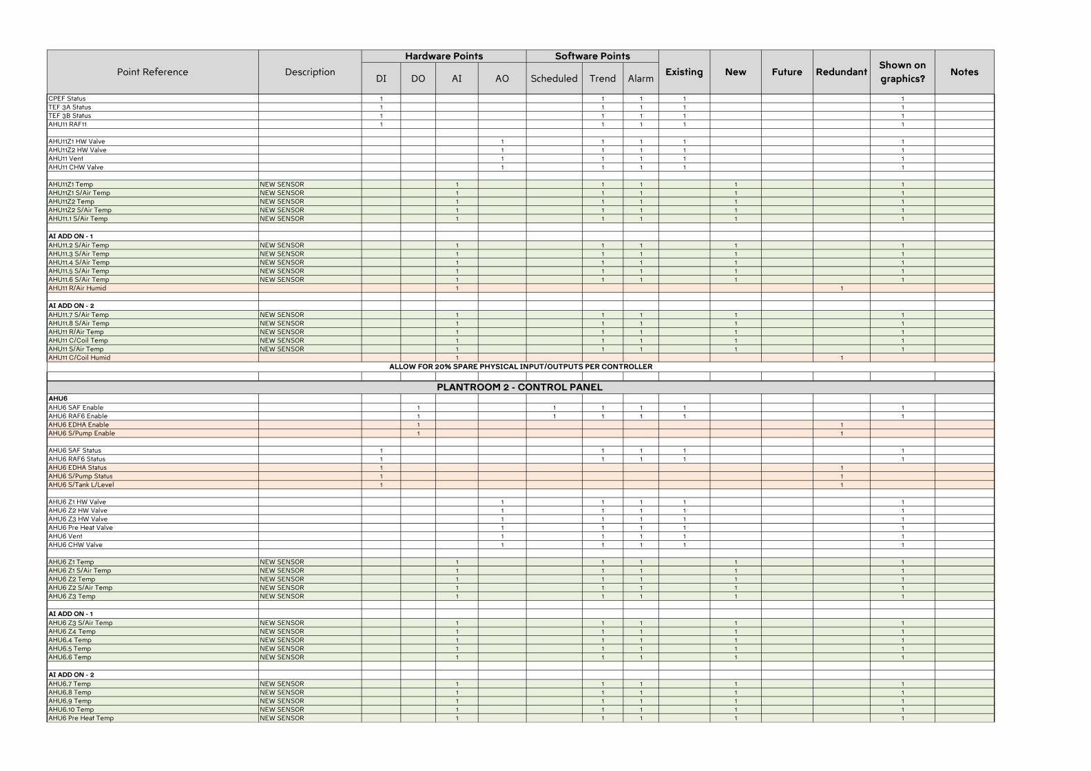
DI DO AI AO Scheduled Trend AlarmExisting New Redundant
Shown on
graphics?NotesPoint Reference Description Future
Hardware Points Software Points
CPEF Status 1 1 1 1 1TEF 3A Status 1 1 1 1 1TEF 3B Status 1 1 1 1 1AHU11 RAF11 1 1 1 1 1
AHU11Z1 HW Valve 1 1 1 1 1AHU11Z2 HW Valve 1 1 1 1 1AHU11 Vent 1 1 1 1 1AHU11 CHW Valve 1 1 1 1 1
AHU11Z1 Temp NEW SENSOR 1 1 1 1 1AHU11Z1 S/Air Temp NEW SENSOR 1 1 1 1 1AHU11Z2 Temp NEW SENSOR 1 1 1 1 1AHU11Z2 S/Air Temp NEW SENSOR 1 1 1 1 1AHU11.1 S/Air Temp NEW SENSOR 1 1 1 1 1
AI ADD ON - 1
AHU11.2 S/Air Temp NEW SENSOR 1 1 1 1 1AHU11.3 S/Air Temp NEW SENSOR 1 1 1 1 1AHU11.4 S/Air Temp NEW SENSOR 1 1 1 1 1AHU11.5 S/Air Temp NEW SENSOR 1 1 1 1 1AHU11.6 S/Air Temp NEW SENSOR 1 1 1 1 1AHU11 R/Air Humid 1 1
AI ADD ON - 2
AHU11.7 S/Air Temp NEW SENSOR 1 1 1 1 1AHU11.8 S/Air Temp NEW SENSOR 1 1 1 1 1AHU11 R/Air Temp NEW SENSOR 1 1 1 1 1AHU11 C/Coil Temp NEW SENSOR 1 1 1 1 1AHU11 S/Air Temp NEW SENSOR 1 1 1 1 1AHU11 C/Coil Humid 1 1
AHU6
AHU6 SAF Enable 1 1 1 1 1 1AHU6 RAF6 Enable 1 1 1 1 1 1AHU6 EDHA Enable 1 1AHU6 S/Pump Enable 1 1
AHU6 SAF Status 1 1 1 1 1AHU6 RAF6 Status 1 1 1 1 1AHU6 EDHA Status 1 1AHU6 S/Pump Status 1 1AHU6 S/Tank L/Level 1 1
AHU6 Z1 HW Valve 1 1 1 1 1AHU6 Z2 HW Valve 1 1 1 1 1AHU6 Z3 HW Valve 1 1 1 1 1AHU6 Pre Heat Valve 1 1 1 1 1AHU6 Vent 1 1 1 1 1AHU6 CHW Valve 1 1 1 1 1
AHU6 Z1 Temp NEW SENSOR 1 1 1 1 1AHU6 Z1 S/Air Temp NEW SENSOR 1 1 1 1 1AHU6 Z2 Temp NEW SENSOR 1 1 1 1 1AHU6 Z2 S/Air Temp NEW SENSOR 1 1 1 1 1AHU6 Z3 Temp NEW SENSOR 1 1 1 1 1
AI ADD ON - 1
AHU6 Z3 S/Air Temp NEW SENSOR 1 1 1 1 1AHU6 Z4 Temp NEW SENSOR 1 1 1 1 1AHU6.4 Temp NEW SENSOR 1 1 1 1 1AHU6.5 Temp NEW SENSOR 1 1 1 1 1AHU6.6 Temp NEW SENSOR 1 1 1 1 1
AI ADD ON - 2
AHU6.7 Temp NEW SENSOR 1 1 1 1 1AHU6.8 Temp NEW SENSOR 1 1 1 1 1AHU6.9 Temp NEW SENSOR 1 1 1 1 1AHU6.10 Temp NEW SENSOR 1 1 1 1 1AHU6 Pre Heat Temp NEW SENSOR 1 1 1 1 1
ALLOW FOR 20% SPARE PHYSICAL INPUT/OUTPUTS PER CONTROLLER
PLANTROOM 2 - CONTROL PANEL
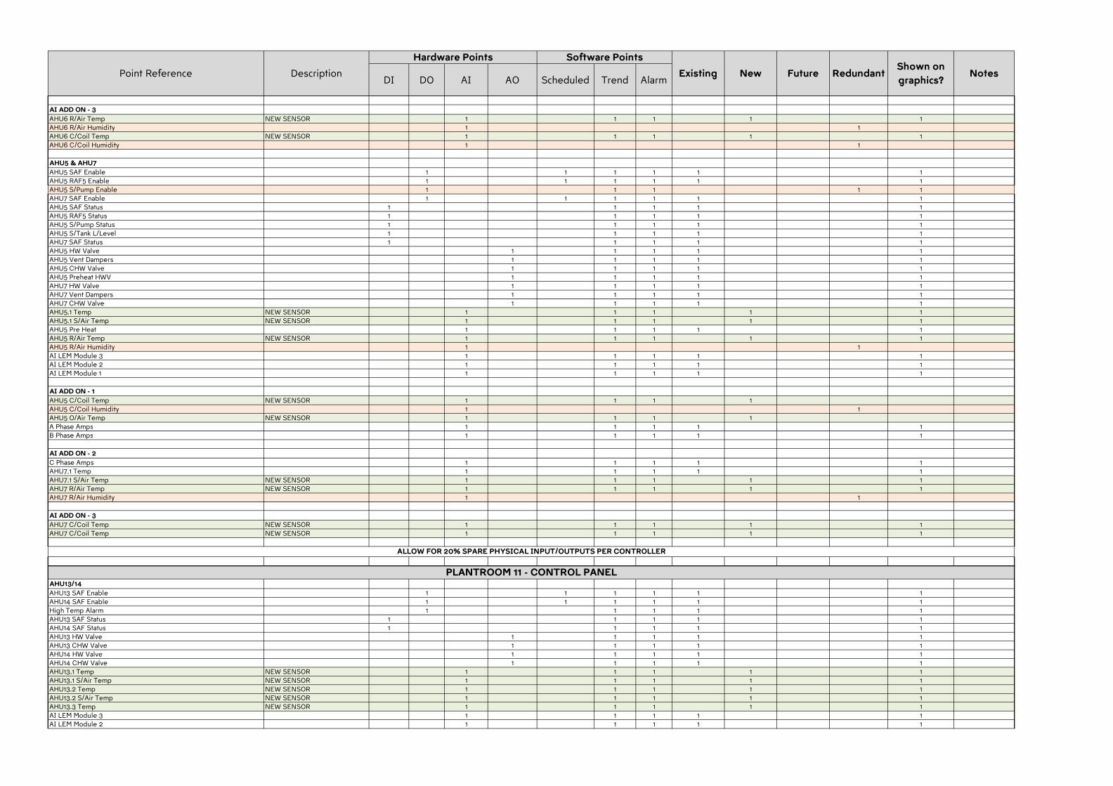
DI DO AI AO Scheduled Trend AlarmExisting New Redundant
Shown on
graphics?NotesPoint Reference Description Future
Hardware Points Software Points
AI ADD ON - 3
AHU6 R/Air Temp NEW SENSOR 1 1 1 1 1AHU6 R/Air Humidity 1 1AHU6 C/Coil Temp NEW SENSOR 1 1 1 1 1AHU6 C/Coil Humidity 1 1
AHU5 & AHU7
AHU5 SAF Enable 1 1 1 1 1 1AHU5 RAF5 Enable 1 1 1 1 1 1AHU5 S/Pump Enable 1 1 1 1 1AHU7 SAF Enable 1 1 1 1 1 1AHU5 SAF Status 1 1 1 1 1AHU5 RAF5 Status 1 1 1 1 1AHU5 S/Pump Status 1 1 1 1 1AHU5 S/Tank L/Level 1 1 1 1 1AHU7 SAF Status 1 1 1 1 1AHU5 HW Valve 1 1 1 1 1AHU5 Vent Dampers 1 1 1 1 1AHU5 CHW Valve 1 1 1 1 1AHU5 Preheat HWV 1 1 1 1 1AHU7 HW Valve 1 1 1 1 1AHU7 Vent Dampers 1 1 1 1 1AHU7 CHW Valve 1 1 1 1 1AHU5.1 Temp NEW SENSOR 1 1 1 1 1AHU5.1 S/Air Temp NEW SENSOR 1 1 1 1 1AHU5 Pre Heat 1 1 1 1 1AHU5 R/Air Temp NEW SENSOR 1 1 1 1 1AHU5 R/Air Humidity 1 1AI LEM Module 3 1 1 1 1 1AI LEM Module 2 1 1 1 1 1AI LEM Module 1 1 1 1 1 1
AI ADD ON - 1
AHU5 C/Coil Temp NEW SENSOR 1 1 1 1AHU5 C/Coil Humidity 1 1AHU5 O/Air Temp NEW SENSOR 1 1 1 1A Phase Amps 1 1 1 1 1B Phase Amps 1 1 1 1 1
AI ADD ON - 2
C Phase Amps 1 1 1 1 1AHU7.1 Temp 1 1 1 1 1AHU7.1 S/Air Temp NEW SENSOR 1 1 1 1 1AHU7 R/Air Temp NEW SENSOR 1 1 1 1 1AHU7 R/Air Humidity 1 1
AI ADD ON - 3
AHU7 C/Coil Temp NEW SENSOR 1 1 1 1 1AHU7 C/Coil Temp NEW SENSOR 1 1 1 1 1
AHU13/14
AHU13 SAF Enable 1 1 1 1 1 1AHU14 SAF Enable 1 1 1 1 1 1High Temp Alarm 1 1 1 1 1AHU13 SAF Status 1 1 1 1 1AHU14 SAF Status 1 1 1 1 1AHU13 HW Valve 1 1 1 1 1AHU13 CHW Valve 1 1 1 1 1AHU14 HW Valve 1 1 1 1 1AHU14 CHW Valve 1 1 1 1 1AHU13.1 Temp NEW SENSOR 1 1 1 1 1AHU13.1 S/Air Temp NEW SENSOR 1 1 1 1 1AHU13.2 Temp NEW SENSOR 1 1 1 1 1AHU13.2 S/Air Temp NEW SENSOR 1 1 1 1 1AHU13.3 Temp NEW SENSOR 1 1 1 1 1AI LEM Module 3 1 1 1 1 1AI LEM Module 2 1 1 1 1 1
ALLOW FOR 20% SPARE PHYSICAL INPUT/OUTPUTS PER CONTROLLER
PLANTROOM 11 - CONTROL PANEL
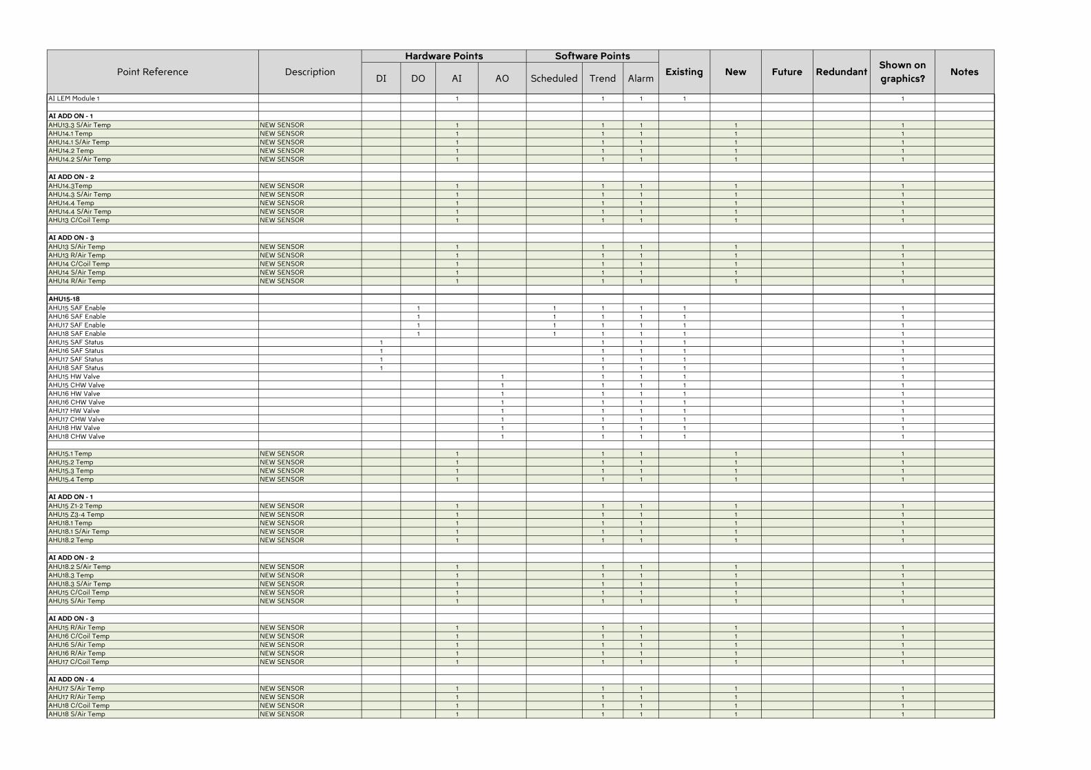
DI DO AI AO Scheduled Trend AlarmExisting New Redundant
Shown on
graphics?NotesPoint Reference Description Future
Hardware Points Software Points
AI LEM Module 1 1 1 1 1 1
AI ADD ON - 1
AHU13.3 S/Air Temp NEW SENSOR 1 1 1 1 1AHU14.1 Temp NEW SENSOR 1 1 1 1 1AHU14.1 S/Air Temp NEW SENSOR 1 1 1 1 1AHU14.2 Temp NEW SENSOR 1 1 1 1 1AHU14.2 S/Air Temp NEW SENSOR 1 1 1 1 1
AI ADD ON - 2
AHU14.3Temp NEW SENSOR 1 1 1 1 1AHU14.3 S/Air Temp NEW SENSOR 1 1 1 1 1AHU14.4 Temp NEW SENSOR 1 1 1 1 1AHU14.4 S/Air Temp NEW SENSOR 1 1 1 1 1AHU13 C/Coil Temp NEW SENSOR 1 1 1 1 1
AI ADD ON - 3
AHU13 S/Air Temp NEW SENSOR 1 1 1 1 1AHU13 R/Air Temp NEW SENSOR 1 1 1 1 1AHU14 C/Coil Temp NEW SENSOR 1 1 1 1 1AHU14 S/Air Temp NEW SENSOR 1 1 1 1 1AHU14 R/Air Temp NEW SENSOR 1 1 1 1 1
AHU15-18
AHU15 SAF Enable 1 1 1 1 1 1AHU16 SAF Enable 1 1 1 1 1 1AHU17 SAF Enable 1 1 1 1 1 1AHU18 SAF Enable 1 1 1 1 1 1AHU15 SAF Status 1 1 1 1 1AHU16 SAF Status 1 1 1 1 1AHU17 SAF Status 1 1 1 1 1AHU18 SAF Status 1 1 1 1 1AHU15 HW Valve 1 1 1 1 1AHU15 CHW Valve 1 1 1 1 1AHU16 HW Valve 1 1 1 1 1AHU16 CHW Valve 1 1 1 1 1AHU17 HW Valve 1 1 1 1 1AHU17 CHW Valve 1 1 1 1 1AHU18 HW Valve 1 1 1 1 1AHU18 CHW Valve 1 1 1 1 1
AHU15.1 Temp NEW SENSOR 1 1 1 1 1AHU15.2 Temp NEW SENSOR 1 1 1 1 1AHU15.3 Temp NEW SENSOR 1 1 1 1 1AHU15.4 Temp NEW SENSOR 1 1 1 1 1
AI ADD ON - 1
AHU15 Z1-2 Temp NEW SENSOR 1 1 1 1 1AHU15 Z3-4 Temp NEW SENSOR 1 1 1 1 1AHU18.1 Temp NEW SENSOR 1 1 1 1 1AHU18.1 S/Air Temp NEW SENSOR 1 1 1 1 1AHU18.2 Temp NEW SENSOR 1 1 1 1 1
AI ADD ON - 2
AHU18.2 S/Air Temp NEW SENSOR 1 1 1 1 1AHU18.3 Temp NEW SENSOR 1 1 1 1 1AHU18.3 S/Air Temp NEW SENSOR 1 1 1 1 1AHU15 C/Coil Temp NEW SENSOR 1 1 1 1 1AHU15 S/Air Temp NEW SENSOR 1 1 1 1 1
AI ADD ON - 3
AHU15 R/Air Temp NEW SENSOR 1 1 1 1 1AHU16 C/Coil Temp NEW SENSOR 1 1 1 1 1AHU16 S/Air Temp NEW SENSOR 1 1 1 1 1AHU16 R/Air Temp NEW SENSOR 1 1 1 1 1AHU17 C/Coil Temp NEW SENSOR 1 1 1 1 1
AI ADD ON - 4
AHU17 S/Air Temp NEW SENSOR 1 1 1 1 1AHU17 R/Air Temp NEW SENSOR 1 1 1 1 1AHU18 C/Coil Temp NEW SENSOR 1 1 1 1 1AHU18 S/Air Temp NEW SENSOR 1 1 1 1 1
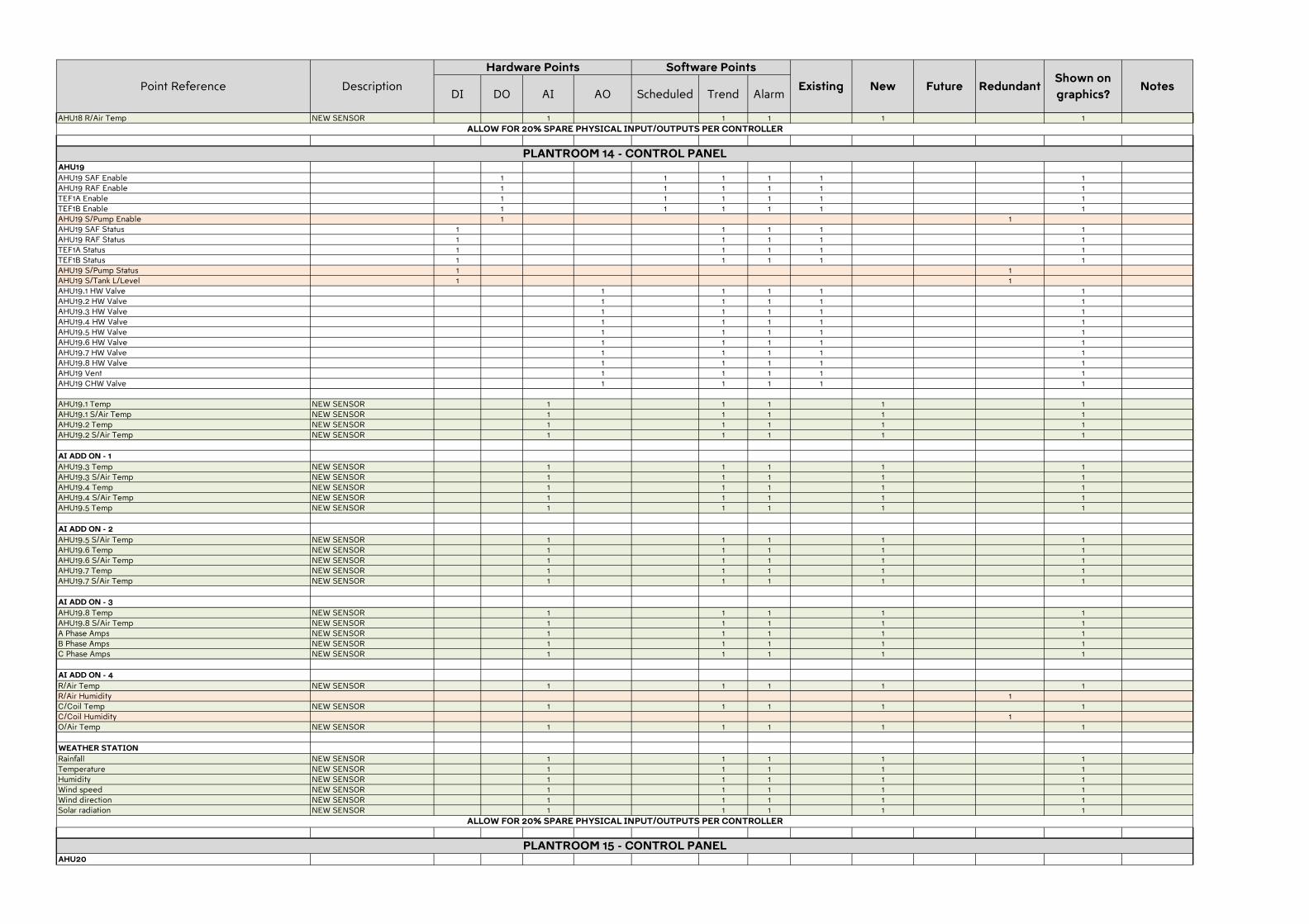
DI DO AI AO Scheduled Trend AlarmExisting New Redundant
Shown on
graphics?NotesPoint Reference Description Future
Hardware Points Software Points
AHU18 R/Air Temp NEW SENSOR 1 1 1 1 1
AHU19
AHU19 SAF Enable 1 1 1 1 1 1AHU19 RAF Enable 1 1 1 1 1 1TEF1A Enable 1 1 1 1 1 1TEF1B Enable 1 1 1 1 1 1AHU19 S/Pump Enable 1 1AHU19 SAF Status 1 1 1 1 1AHU19 RAF Status 1 1 1 1 1TEF1A Status 1 1 1 1 1TEF1B Status 1 1 1 1 1AHU19 S/Pump Status 1 1AHU19 S/Tank L/Level 1 1AHU19.1 HW Valve 1 1 1 1 1AHU19.2 HW Valve 1 1 1 1 1AHU19.3 HW Valve 1 1 1 1 1AHU19.4 HW Valve 1 1 1 1 1AHU19.5 HW Valve 1 1 1 1 1AHU19.6 HW Valve 1 1 1 1 1AHU19.7 HW Valve 1 1 1 1 1AHU19.8 HW Valve 1 1 1 1 1AHU19 Vent 1 1 1 1 1AHU19 CHW Valve 1 1 1 1 1
AHU19.1 Temp NEW SENSOR 1 1 1 1 1AHU19.1 S/Air Temp NEW SENSOR 1 1 1 1 1AHU19.2 Temp NEW SENSOR 1 1 1 1 1AHU19.2 S/Air Temp NEW SENSOR 1 1 1 1 1
AI ADD ON - 1
AHU19.3 Temp NEW SENSOR 1 1 1 1 1AHU19.3 S/Air Temp NEW SENSOR 1 1 1 1 1AHU19.4 Temp NEW SENSOR 1 1 1 1 1AHU19.4 S/Air Temp NEW SENSOR 1 1 1 1 1AHU19.5 Temp NEW SENSOR 1 1 1 1 1
AI ADD ON - 2
AHU19.5 S/Air Temp NEW SENSOR 1 1 1 1 1AHU19.6 Temp NEW SENSOR 1 1 1 1 1AHU19.6 S/Air Temp NEW SENSOR 1 1 1 1 1AHU19.7 Temp NEW SENSOR 1 1 1 1 1AHU19.7 S/Air Temp NEW SENSOR 1 1 1 1 1
AI ADD ON - 3
AHU19.8 Temp NEW SENSOR 1 1 1 1 1AHU19.8 S/Air Temp NEW SENSOR 1 1 1 1 1A Phase Amps NEW SENSOR 1 1 1 1 1B Phase Amps NEW SENSOR 1 1 1 1 1C Phase Amps NEW SENSOR 1 1 1 1 1
AI ADD ON - 4
R/Air Temp NEW SENSOR 1 1 1 1 1R/Air Humidity 1C/Coil Temp NEW SENSOR 1 1 1 1 1C/Coil Humidity 1O/Air Temp NEW SENSOR 1 1 1 1 1
WEATHER STATION
Rainfall NEW SENSOR 1 1 1 1 1Temperature NEW SENSOR 1 1 1 1 1Humidity NEW SENSOR 1 1 1 1 1Wind speed NEW SENSOR 1 1 1 1 1Wind direction NEW SENSOR 1 1 1 1 1Solar radiation NEW SENSOR 1 1 1 1 1
AHU20
ALLOW FOR 20% SPARE PHYSICAL INPUT/OUTPUTS PER CONTROLLER
ALLOW FOR 20% SPARE PHYSICAL INPUT/OUTPUTS PER CONTROLLER
PLANTROOM 14 - CONTROL PANEL
PLANTROOM 15 - CONTROL PANEL
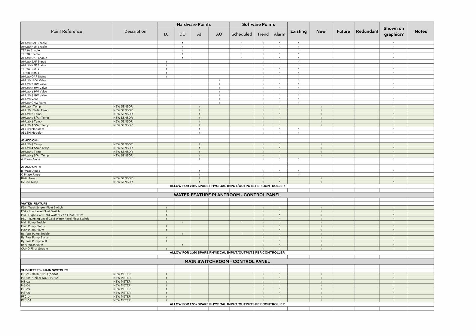
DI DO AI AO Scheduled Trend AlarmExisting New Redundant
Shown on
graphics?NotesPoint Reference Description Future
Hardware Points Software Points
AHU20 SAF Enable 1 1 1 1 1 1AHU20 KEF Enable 1 1 1 1 1 1TEF2A Enable 1 1 1 1 1 1TEF2B Enable 1 1 1 1 1 1AHU20 OAF Enable 1 1 1 1 1 1AHU20 SAF Status 1 1 1 1 1AHU20 KEF Status 1 1 1 1 1TEF2A Status 1 1 1 1 1TEF2B Status 1 1 1 1 1AHU20 OAF Status 1 1 1 1 1AHU20.1 HW Valve 1 1 1 1 1AHU20.2 HW Valve 1 1 1 1 1AHU20.3 HW Valve 1 1 1 1 1AHU20.4 HW Valve 1 1 1 1 1AHU20.5 HW Valve 1 1 1 1 1AHU20 Vent 1 1 1 1 1AHU20 CHW Valve 1 1 1 1 1AHU20.1 Temp NEW SENSOR 1 1 1 1 1AHU20.1 S/Air Temp NEW SENSOR 1 1 1 1 1AHU20.2 Temp NEW SENSOR 1 1 1 1 1AHU20.2 S/Air Temp NEW SENSOR 1 1 1 1 1AHU20.3 Temp NEW SENSOR 1 1 1 1 1AHU20.3 S/Air Temp NEW SENSOR 1 1 1 1 1AI LEM Module 2 1 1 1 1 1AI LEM Module 1 1 1 1 1 1
AI ADD ON - 1
AHU20.4 Temp NEW SENSOR 1 1 1 1 1AHU20.4 S/Air Temp NEW SENSOR 1 1 1 1 1AHU20.5 Temp NEW SENSOR 1 1 1 1 1AHU20.5 S/Air Temp NEW SENSOR 1 1 1 1 1A Phase Amps 1 1 1 1 1
AI ADD ON - 2
B Phase Amps 1 1 1 1 1C Phase Amps 1 1 1 1 1R/Air Temp NEW SENSOR 1 1 1 1 1C/Coil Temp NEW SENSOR 1 1 1 1 1
WATER FEATURE
FS1 - Trash Screen Float Switch 1 1 1 1 1FS2 - Low Level Float Switch 1 1 1 1 1PS1 - High Level Cold Water Feed Float Switch 1 1 1 1 1PS2 - Running Level Cold Water Feed Flow Switch 1 1 1 1 1Main Pump Enable 1 1 1 1 1 1Main Pump Status 1 1 1 1 1Main Pump Alarm 1 1 1 1 1By-Pass Pump Enable 1 1 1 1 1 1By-Pass Pump Status 1 1 1 1 1By-Pass Pump Fault 1 1 1 1 1Back-Wash Valve 1 1 1 1 1CUNO Filter System 1 1 1 1 1
SUB-METERS - MAIN SWITCHES
MS-01 - Chiller No. 1 (500A) NEW METER 1 1 1 1 1MS-02 - Chiller No. 2 (500A) NEW METER 1 1 1 1 1MS-03 NEW METER 1 1 1 1 1MS-04 NEW METER 1 1 1 1 1MS-05 NEW METER 1 1 1 1 1MS-06 NEW METER 1 1 1 1 1PFC-01 NEW METER 1 1 1 1 1PFC-02 NEW METER 1 1 1 1 1
WATER FEATURE PLANTROOM - CONTROL PANEL
MAIN SWITCHROOM - CONTROL PANEL
ALLOW FOR 20% SPARE PHYSICAL INPUT/OUTPUTS PER CONTROLLER
ALLOW FOR 20% SPARE PHYSICAL INPUT/OUTPUTS PER CONTROLLER
ALLOW FOR 20% SPARE PHYSICAL INPUT/OUTPUTS PER CONTROLLER
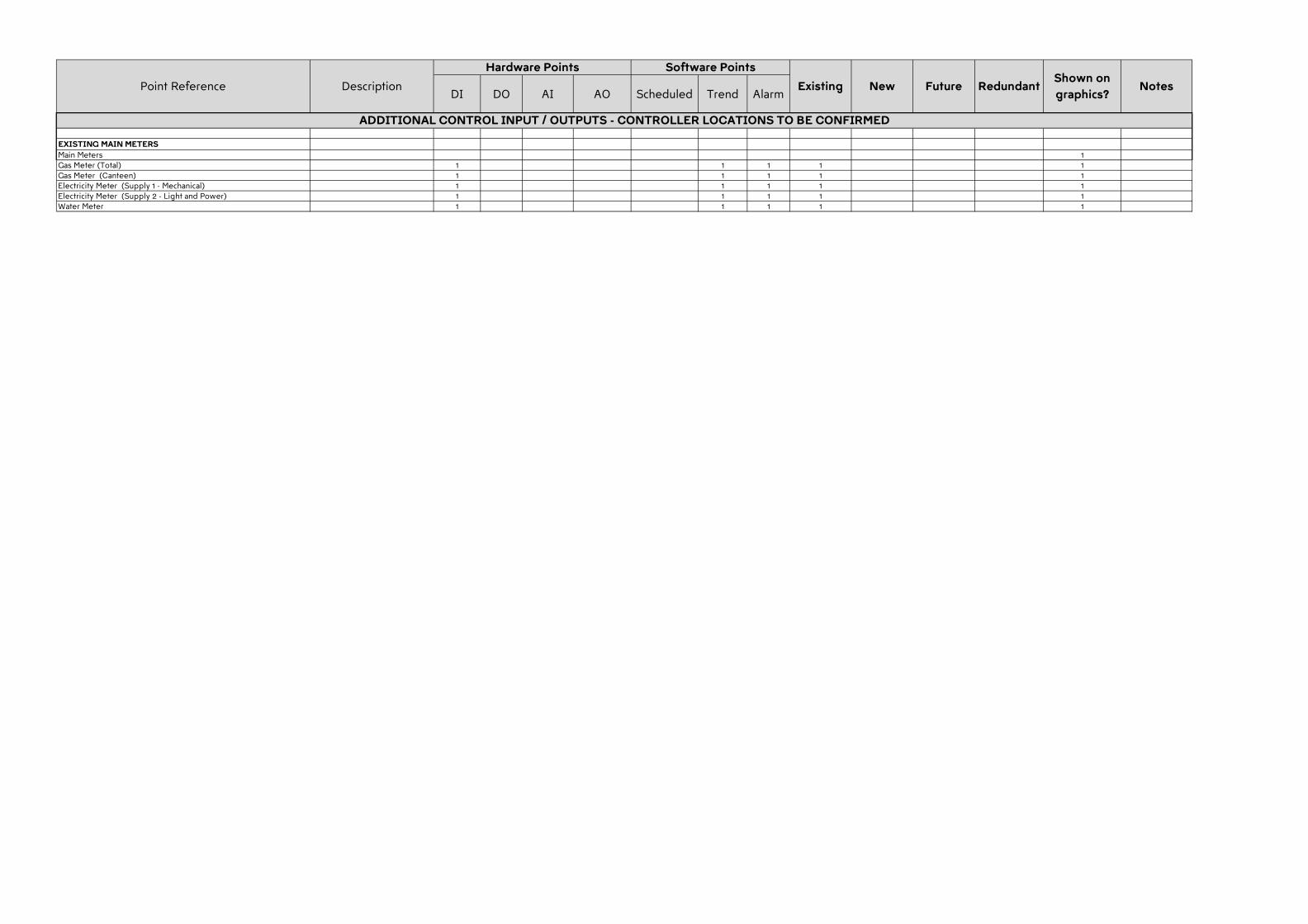
DI DO AI AO Scheduled Trend AlarmExisting New Redundant
Shown on
graphics?NotesPoint Reference Description Future
Hardware Points Software Points
EXISTING MAIN METERS
Main Meters 1Gas Meter (Total) 1 1 1 1 1Gas Meter (Canteen) 1 1 1 1 1Electricity Meter (Supply 1 - Mechanical) 1 1 1 1 1Electricity Meter (Supply 2 - Light and Power) 1 1 1 1 1Water Meter 1 1 1 1 1
ADDITIONAL CONTROL INPUT / OUTPUTS - CONTROLLER LOCATIONS TO BE CONFIRMED
Engineering services enable architecture. Sean Mulcahy
Mechanical Engineering Lighting Design Sustainable Design Electrical Engineering
Copenhagen London Sydney Hong Kong New York
GF, 218 Northbourne Avenue Braddon, ACT, 2612, Australia ABN 50 001 189 037 t : +61 / 02 6230 0502 e : [email protected]
STEENSEN VARMING
Page 79 / 79 steensenvarming.com
6.0 Appendix B – As-Built Documentation for Information
6.1 Electrical Single Line Diagram
6.2 Existing LAN Cabling Schematic