Specification PTC 251 Technical Requirements for Permission to
21
i PTC 251: 1987 Specification PTC 251 Technical Requirements for Permission to Connect Radio Paging Receivers Access Standards Spark New Zealand Limited Wellington New Zealand
Transcript of Specification PTC 251 Technical Requirements for Permission to

i PTC 251: 1987
Specification PTC 251 Technical Requirements
for Permission to Connect Radio Paging Receivers
Access Standards
Spark New Zealand Limited
Wellington
New Zealand
PTC 251: 1987 ii
CONTENT
Section Page
1. SCOPE .............................................................................................................. 1 2. INTRODUCTION ............................................................................................... 1 3. GENERAL REQUIREMENTS ........................................................................... 1 4. REQUIREMENTS FOR RADIO-PAGING RECEIVERS .................................... 3
4.1 General ..................................................................................................... 3 4.2 Procedure ................................................................................................. 3 4.3 Specifications ............................................................................................ 4
APPENDIX 1: RADIO-PAGING CODE NO. 1 ......................................................... 5 1. Code and Format ............................................................................................ 5
1.1 Preamble .................................................................................................. 6 1.2 Batch structure .......................................................................................... 6 1.3 Types of codewords .................................................................................. 6 1.3.1 Synchronization Codeword .................................................................... 8 1.3.2 Address Codewords ............................................................................... 8 1.3.3 Message Codewords ............................................................................. 8 1.3.4 Idle Codeword ........................................................................................ 9 1.4 Codeword Generation (31:21 BCH + Parity) ............................................. 9
2. Message Formats ........................................................................................... 9 2.1 “Numeric-only” message format ................................................................ 9 2.2 Alpha-numeric or general data format ..................................................... 10
APPENDIX 2: COMPATIBILITY REQUIREMENTS FOR FREQUENCY AND MODULATION CHARACTERISTICS ................................................................... 12
1. Operating Frequency .................................................................................... 12 2. Transmission Rate ........................................................................................ 12 3. Modulation .................................................................................................... 12 4. Modulation Rise Time ................................................................................... 12 5. Line Delay Differential ................................................................................ 12 6. Prolonged Mark Or Space Transmissions ................................................. 12
APPENDIX 3: MINIMUM PERFORMANCE REQUIREMENTS FOR SENSITIVITY ANDSPURIOUS RADIATION ............................................................................... 13
1. Sensitivity ...................................................................................................... 13 2. Spurious Radiation........................................................................................ 13 3. Mutual Interference ....................................................................................... 13
APPENDIX 4: RECOMMENDED MINIMUM PERFORMANCE, OPERATIONAL AND CUSTOMER REQUIREMENTS .................................................................... 14
1. Radio Interferance Requirements ................................................................. 14 1.1 Desensitisation........................................................................................ 14 1.2 Frequency Tolerance .............................................................................. 14 1.3 Selectivity ................................................................................................ 14
2. Decoding Requirements ............................................................................... 14 2.1 Code Range ............................................................................................ 14 2.2 Multiple Alerts ......................................................................................... 14 2.3 Idle Codeword ......................................................................................... 15

iii PTC 251: 1987
2.4 Synchronisation Recovery ...................................................................... 16 2.5 Error Detection and Correction ............................................................... 16 2.6 Message Termination ............................................................................. 16 2.7 Falsing Rates .......................................................................................... 16 2.8 Decoding Reliability ................................................................................ 16 2.9 Memory Storage ..................................................................................... 16
3. Environmental Requirements ........................................................................ 16 4. Mechanical Requirements ............................................................................ 17
4.1 Size and Weight ...................................................................................... 17 4.2 Ruggedness ............................................................................................ 17 4.3 Battery .................................................................................................... 17 4.4 Access to circuitry ................................................................................... 17
5 Reliability ...................................................................................................... 17 6. Optional Features ......................................................................................... 17
COPYRIGHT ACKNOWLEGEMENT
The Telecom Corporation of New Zealand gratefully acknowledges that the following texts contained in Appendix 1 are reproduced with the prior authorization of the ITU as the copyright-holder:-
a) “Radio-Paging Code No. 1” contained in Annex 1 b Recommendation 584-1 (Standard Codes and Formats for International Radio Paging) of the ITU-R and published in Volume VIII-1, pages 64-67 of the ITU publication “ITU-R – recommendations and Reports of the ITU-R, 1986, XVIth Plenary Assembly, Dubrovnik, 1986”.
b) “Table 11/T.50 (International Reference Version (IRV))” contained in Recommendation T.50 (International Alphabet No. 5) of the CCITT and published in Volume Vll - fascicle VII.3, page 134, of the ITU publication “CCITT – Red Book, Terminal Equipment and Protocols for Telematic Services – Recommendations of the T. Series, VIIIth Plenary Assembly, Malaga-Torremolinos, 8-19 October 1984”.


1 PTC 251: 1987
1. SCOPE
This specification defines the requirements of radio-paging receivers for use on the Telepaging Service Network operated by the Telecom Corporation of New Zealand.
2. INTRODUCTION
Telecom provides a national radio-paging system, known as the Telepaging Service, using a digital code which has an addressing capacity of over 2 million addresses and is capable of providing a wide range of message facilities including tone-only, numeric and alpha-numeric messaging.
The digital code specification is based on a report by the British Post Office (now British Telecom) titled “A Standard Code for Radiopaging - A report of the Studies of the British Post Office Standardisation Advisory Group” and the code is commonly known as the POCSAG code.
The POCSAG code has subsequently also been adopted by the International Radio Consultative Committee (ITU-R), a body of the ITU, as Radio-Paging Code No. 1 and published as ITU-R Recommendation 584-1.
Further information on the performance characteristics of the POCSAG code may be found in “The Book of the ITU-R Radiopaging Code No.1”.
The Telecom Telepaging Service operates on the frequency of 157.925 MHz and at a signalling rate of 512 Baud.
3. GENERAL REQUIREMENTS
All paging receivers used on the New Zealand Telepaging Service Network are required to bear a Permit to Connect label and comply with Telecom requirements for network connection. Specification PTC 100 defines the general conditions for granting a Permit to Connect. This specification defines the specific requirements for radio paging receivers which are based on overseas standards and specifications and cover, system compatibility and performance aspects. Where there is a conflict between the requirements of PTC 100 and the requirements of this specification then this specification shall prevail.

PTC 251: 1987 2
There is no specific Radio Frequency Service approval requirement for paging receivers.
Figure 1 outlines the approval process.
PAGER SUPPLIER
TELECOM
Figure 1: The Permission to Connect Process
for POCSAG Pagers
Apply to Telecom for Permission to Connect (PTC) documents.
Apply to Mobile Engineering for Permission to Connect
as per PTC 251. NB. Include documentation and two pager samples.
Apply to Mobile Engineering for a block of
POCSAG Codes for programming pagers during manufacture.
Pager can commence service.
On-going
Telecom – Supplier liaison
Telecom sends copy of specifications PTC 100 and PTC 251 detailing
requirements for Permission to Connect.
Mobile Engineering issues
Permit to Connect number to supplier.
Mobile Engineering retains one
representative sample and documentation. All else returned to supplier
Mobile Engineering supplies block of
POCSAG Codes for supplier use.
1
2
3
4
5
6
7
8

3 PTC 251: 1987
4. REQUIREMENTS FOR RADIO-PAGING RECEIVERS
4.1 General
The granting of a Permit to Connect will be based on a declaration by the pager manufacturer/supplier that equipment meets the requirements of this specification. This declaration is termed “attestation” and the procedure is described in para. 4.2.
An application fee of $300 inclusive of GST will be charged for carrying out Permission to Connect assessments. Where additional inspections or quality control audits are required additional negotiated charges will be made.
4.2 Procedure
Manufacturers/Suppliers seeking Permission to Connect are required to:
(1) Submit attestation that the paging receiver submitted for Permission to Connect complies with:
(a) the protocol and message code format specification for Radio-Paging Code No. 1 contained in ITU-R Recommendation 584-1 attached as Appendix 1.
(b) the compatibility requirements for frequency and transmission characteristics attached as Appendix 2.
(c) the minimum performance requirements for sensitivity and spurious radiation attached as Appendix 3.
This attestation shall be a signed declaration by a Senior Manager in an appropriate position in the Manufacturers organisation, and shall include details of any particular areas where the receiver performance is different to that in this specification.
The issue of a Permit to Connect will be conditional on equipment operating in accordance with the attested performance standards. If an in service problem develops because a particular type of receiver does not comply with the attested performance, then the Permit to Connect may be revoked and all pagers of this type disconnected from the network until the problem is corrected.
(2) Supply two sample pager units, complete with any accessories, operation manuals and service manuals. Sample units are to be programmed with the POCSAG code 1500020.
With the agreement of the manufacturer/supplier, one unit including one copy of the operations and maintenance manuals will be retained by Telecom for a negotiated period, for use with system tests and on-going network support. The second unit will be returned to the manufacturer/supplier upon completion of approval assessment.
(3) Note the minimum recommended performance, operation and customer requirements considered necessary for satisfactory use on the New Zealand Telepaging Service contained in Appendix 4 to this specification.

PTC 251: 1987 4
In carrying out assessments of the suitability for the granting of Permission to Connect Telecom reserves the right to:
- request the supply of additional information as required - audit test results, methods and procedures - request the supply of additional sample units for inspection and operational testing - review Permission to Connect
Applications for Permission to Connect including the $300 fee should be made to:
Section Manager Mobile Engineering Section Marketing Group Telecom Head Office Private Bag WELLINGTON
When Permission to Connect is granted a Permit number will be issued. This number will be of the form PTC 251/YY/NNN and shall be displayed on all pager units used on the Telecom Telepaging Service.
4.3 Specifications
The following specifications are attached as appendices:
Appendix 1 RADIO-PAGING CODE NO. 1 (Annex 1 to ITU-R Recommendation 584-1 ) Protocol and message code formats.
Appendix 2 Compatibility Requirements for Frequency and Transmission Characteristics.
Appendix 3 Minimum Performance Requirements for Sensitivity and Spurious Radiation.
Appendix 4 Recommended Minimum Performance, Operational and Customer Requirements.

5 PTC 251: 1987
APPENDIX 1: RADIO-PAGING CODE NO. 1
(The following is an extract from Annex 1 of ITU-R Recommendation 584-1 with the addition of Table IV detailing the “Alphanumeric” character set).
RADIO PAGING CODE No. 1
1. Code and Format
A transmission consists of a preamble followed by batches of complete codewords, each batch commencing with a synchronization codeword (SC). The format of the signals is illustrated in Fig 1. Transmission may cease at the end of a batch when there are no further calls.
A B C
S
C
S
C
101010
D
S
C
FIGURE 1 – Signal Format
A: preamble. Duration at least 576 bits = the duration 1 batch + 1 codeword B: first batch C: second and subsequent batches D: one frame = 2 codewords SC: synchronization codeword Note – 1 batch = synchronization codeword + 8 frames = 17 codewords

PTC 251: 1987 6
1.1 Preamble
Each transmission starts with a preamble to aid the pagers to attain bit synchronization and thus help in acquiring word and batch synchronization. The preamble is a pattern of reversals, 101010... repeated for a period of at Ieast 576 bits, i.e. the duration of a batch plus a codeword.
1.2 Batch structure
Codewords are structured in batches which comprise a synchronization codeword followed by 8 frames each containing 2 codewords. The frames are numbered 0 to 7 and the pager population is divided into 8 groups. Thus each pager is allocated to one of the 8 frames according to the 3 least significant bits (1sb) of its 21 bit identity (see § 1.3.2), i.e. 000 = frame 0, 111 - frame 7, and only examines address codewords in that frame. Therefore each pager’s address codewords must be transmitted only in the allocated frame.
Message codewords for any receiver may be transmitted in any frame but follow,
directly, the associated address codeword. A message may consist of any number of codewords transmitted consecutively and may embrace one or more batches but the synchronization codeword must not be displaced by message codewords. Message termination is indicated by the next address codeword or idle codeword. There is at least one address or idle codeword between the end of one message and the address codeword belonging to the next message.
In any batch, wherever there is no meaningful codeword to be transmitted, an idle codeword is transmitted.
1.3 Types of codewords
Codewords contain 32 bits which are transmitted with the most significant bit first.
7 PTC 251: 1987
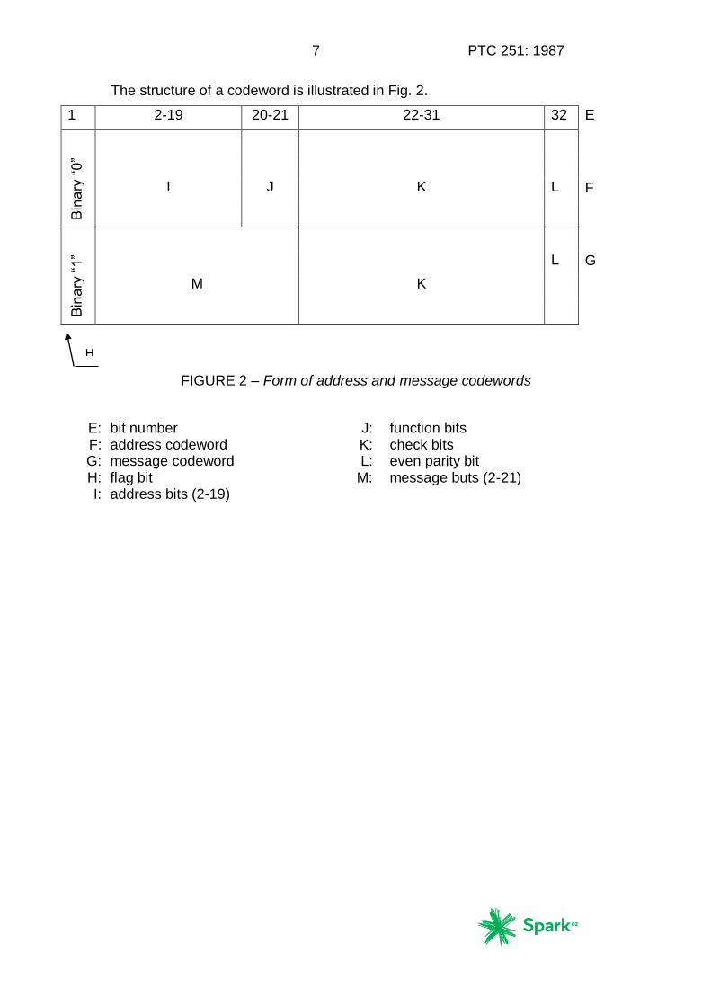
The structure of a codeword is illustrated in Fig. 2.
1 2-19 20-21 22-31 32 E
Bin
ary
“0
”
I
J
K
L
F
Bin
ary
“1
”
M
K
L
G
FIGURE 2 – Form of address and message codewords
E: bit number J: function bits F: address codeword K: check bits G: message codeword L: even parity bit H: flag bit M: message buts (2-21) I: address bits (2-19)
H

PTC 251: 1987 8
1.3.1 Synchronization Codeword
The synchronization codeword is shown in Table I:
TABLE I
Bit No. 1 2 3 4 5 6 7 8 9 10 11 12 13 14 15 16
Bit 0 1 1 1 1 1 0 0 1 1 0 1 0 0 1 0
Bit No. 17 18 19 20 21 22 23 24 25 26 27 28 29 30 31 32
Bit 0 0 0 1 0 1 0 1 1 1 0 1 1 0 0 0
1.3.2 Address Codewords
The structure of an address codeword is illustrated in Fig. 2.
Bit 1 (the flag bit) of an address codeword is always a zero. This distinguishes it from a message codeword.
Bit 2-19 are address bits corresponding to the 18 most significant bits of a 21 bit identity assigned to the pager.
For information regarding the least significant bits see §1.2.
Bits 20 and 21 are the two function bits which are used to select the required address from the four assigned to the pager. Hence the total number of addresses is 223 (over 8 million).
Bits 22 to 31 are the parity check bits (see §1.4) and the final bit (bit 32) is chosen to give even parity.
1.3.3 Message Codewords
The structure of a message codeword is shown in fig. 2. A message codeword always starts with a 1 (the flag bit) and the whole message always follows directly after the address codeword. The framing rules of the code format do not apply to a message and message codewords continue until terminated by the transmission of the next address codeword or idle codeword. Each message displaces at least one address codeword or idle codeword and the displaced address codewords are delayed and transmitted in the next available appropriate frame. Although message codewords may continue into the next batch, the normal batch structure is maintained, i.e., the batch will consist of 16 codewords, preceded by a synchronization codeword. At the conclusion of a message any waiting, address codewords are transmitted, starting with the first appropriate to the first free frame or half frame.
Message codewords have 20 message bits, viz bit 2 to bit 21 inclusive and these are followed by the parity check bits obtained according to the procedure outlined in §1.4 below.

9 PTC 251: 1987
1.3.4 Idle Codeword
In the absence of an address codeword or message codeword, an idle codeword is transmitted. The idle codeword is a valid address codeword, which must not be allocated to pagers and has the following structure as shown in Table II:
TABLE II
Bit No. 1 2 3 4 5 6 7 8 9 10 11 12 13 14 15 16
Bit 0 1 1 1 1 0 1 0 1 0 0 0 1 0 0 1
Bit No. 17 18 19 20 21 22 23 24 25 26 27 28 29 30 31 32
Bit 1 1 0 0 0 0 0 1 1 0 0 1 0 1 1 1
1.4 Codeword Generation (31:21 BCH + Parity)
Each codeword has 21 information bits, which correspond to the coefficients of a polynomial having terms from x30 down to x10. This polynomial is divided, modulo-2, by the generating polynomial x10 + x9 + x8 + x6 + x5 + x3 + 1. The check bits correspond to the coefficients of the terms from X9 to X0 in the remainder polynomial found at the completion of this division. The complete block, consisting of the information bits followed by the check bits, corresponds to the coefficients of a polynomial which is integrally divisible in modulo-2 fashion by the generating polynomial.
To the 31 bits of the block is added one additional bit to provide an even bit parity check of the whole codeword.
2. Message Formats
Although in principle, any message format can be inserted into message codewords, the following formats are regarded as standard. Adherence to these standards will enable a greater measure of interworking to be possible. The formats are not mixed within any one message.
2.1 “Numeric-only” message format
The “numeric-only” format is provided for the transmission of messages which may be represented solely in decimal numerals together with spaces, hyphens, opening and closing brackets, an urgency symbol “U” and one other symbol. There are 4 bits per character in this format and its use will save air-time compared to the other format.
The address which introduces a message (or segment of a message) using this format has its function bits set to 00. The character-set used for the message is as shown in Table III which is based on Binary Coded Decimal (BCD). The bits of each character are transmitted in numerical order starting with bit no. 1. Characters are transmitted in the same order as they are to be read and are packed 5 per message codeword. Any unwanted part of the last codeword of the message is filled with space characters.

PTC 251: 1987 10
TABLE III – “Numeric-only” character set
4-bit Combination Display character
Bit No.: 4 3 2 1
0 0 0 0
0 0 0 1
0 0 1 0
0 0 1 1
0 1 0 0
0 1 0 1
0 1 1 0
0 1 1 1
1 0 0 0
1 0 0 1
1 0 1 0
1 0 1 1
1 1 0 0
1 1 0 1
1 1 1 0
1 1 1 1
0
1
2
3
4
5
6
7
8
9
Spare
U (urgency indicator)
Space
Hyphen
2.2 Alpha-numeric or general data format
This format can be used for the transmission of messages requiring a greater range of characters than that provided within the “numeric-only” format but it may also be used to replace the latter when circumstances make this essential or desirable. There are 7 bits per character in this format.
The pager address which introduces a message (or segment of a message) using this format has its function bits set to 11.
The CCITT Alphabet No. 5 (7 bits per character) is used in this format. As in the case of the “numeric-only” format, bit order starting with bit No.1 of each character, and character reading order are preserved in transmission. The complete message is partitioned into contiguous 20 bit blocks for the purpose of filling consecutive message codewords. Thus a character may be split between one message codeword and the next. Any unwanted part of the last codeword of the message is filled with appropriate non-printing characters such as “End of Message“, “end of Text”, Null, etc. All characters, except Null, are complete.

11 PTC 251: 1987
Table IV: Alphanumeric Character Set (Extracted from CCITT Recommendation T.5O)
Note: This code corresponds to ISO 646 and is commonly known as ASCII
0 0 0 0 1 1 1 1
0 0 1 1 0 0 1 1
Bit No.
7
6
5
4
3
2
1
Column
Row
0 1 0 1 0 1 1 1
0 1 2 3 4 5 6 7
0 0 0 0 0 NUL DLE SP 0 @ P ‘ p
0 0 0 1 1 SOH DC1 ! 1 A Q a q
0 0 1 0 2 STX DC2 “ 2 B R b r
0 0 1 1 3 ETX DC3 £/# 3 C S c s
0 1 0 0 4 EOT DC4 $ 4 D T d t
0 1 0 1 5 ENQ NAK % 5 E U e u
0 1 1 0 6 ACK SYN & 6 F V f v
0 1 1 1 7 BEL ETB ‘ 7 G W g w
1 0 0 0 8 BS CAN ( 8 H X h x
1 0 0 1 9 HT EM ) 9 I Y i y
1 0 1 0 10 LF SUB * : J Z j z
1 0 1 1 11 YT ESC + ; K [ k {
1 1 0 0 12 FF IS4 , < L \ l |
1 1 0 1 13 CR IS3 - = M ] m }
1 1 1 0 14 SO IS2 . > N ^ n _
1 1 1 1 15 SI IS1 / ? O _ o DEL
PTC 251: 1987 12
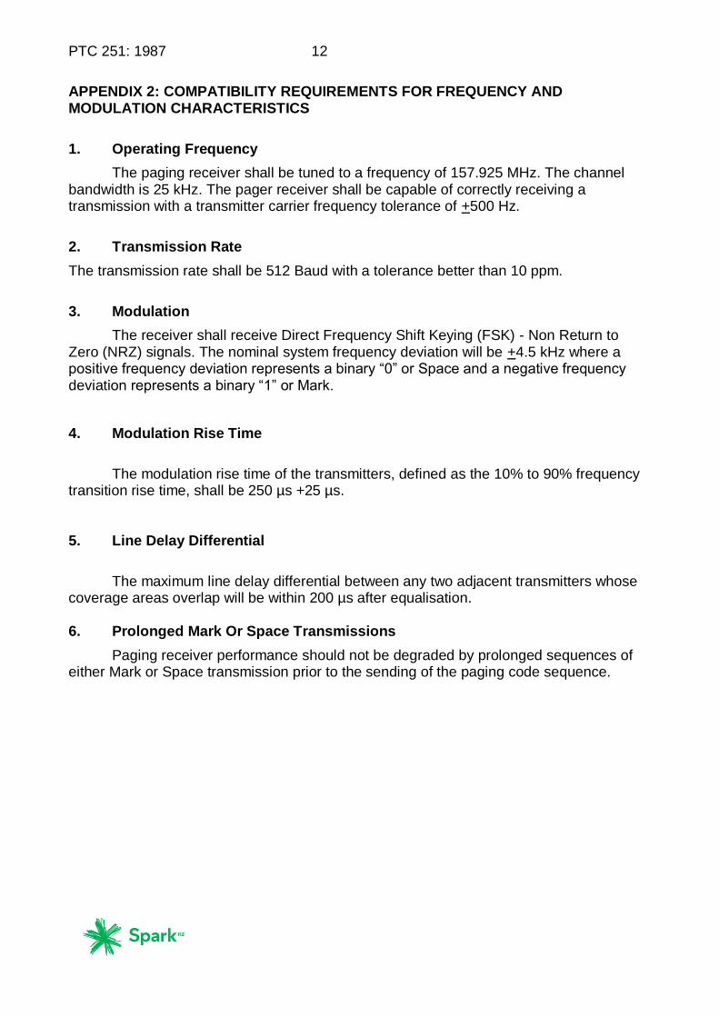
APPENDIX 2: COMPATIBILITY REQUIREMENTS FOR FREQUENCY AND MODULATION CHARACTERISTICS
1. Operating Frequency
The paging receiver shall be tuned to a frequency of 157.925 MHz. The channel bandwidth is 25 kHz. The pager receiver shall be capable of correctly receiving a transmission with a transmitter carrier frequency tolerance of +500 Hz.
2. Transmission Rate
The transmission rate shall be 512 Baud with a tolerance better than 10 ppm.
3. Modulation
The receiver shall receive Direct Frequency Shift Keying (FSK) - Non Return to Zero (NRZ) signals. The nominal system frequency deviation will be +4.5 kHz where a positive frequency deviation represents a binary “0” or Space and a negative frequency deviation represents a binary “1” or Mark.
4. Modulation Rise Time
The modulation rise time of the transmitters, defined as the 10% to 90% frequency
transition rise time, shall be 250 µs +25 µs. 5. Line Delay Differential
The maximum line delay differential between any two adjacent transmitters whose
coverage areas overlap will be within 200 µs after equalisation. 6. Prolonged Mark Or Space Transmissions
Paging receiver performance should not be degraded by prolonged sequences of either Mark or Space transmission prior to the sending of the paging code sequence.

13 PTC 251: 1987
APPENDIX 3: MINIMUM PERFORMANCE REQUIREMENTS FOR SENSITIVITY ANDSPURIOUS RADIATION
1. Sensitivity
The sensitivity, based on the eight position test detailed below, shall be equal to or better than a “dB” average of +20 dB relative to the 1 µV/m signal level.
Measurements shall be made on an unobstructed test range with the correctly modulated signal radiated from a vertical dipole centred 2 m above ground level. At a range of 30 m the receiver under test shall be worn by a person of average build, in the breast pocket at a height of 1.4 m above ground level.
With the person facing the transmitter, the RF signal strength shall be noted at which the receiver operates with a 50% probability to five consecutive calls.
Then at azimuthal intervals of 45°, seven additional measurements shall be taken and an eight position average of the levels, expressed in dB’s, is calculated. This is the receiver sensitivity level. 2. Spurious Radiation
With the receiver oriented to produce maximum field strength at each frequency
radiated, spurious radiation from the receiver shall not exceed a field strength of 20 µV/m at a distance of 3.5 m. 3. Mutual Interference
The pager shall not interfere with the operation of another pager utilising the
super-heterodyning principle, with a sensitivity of +20 dB µV/m, when separated by a minimum distance of 0.5 m. The other pager shall reliably receive its correctly coded Identity at a field strength of +30 dB µV/m.

PTC 251: 1987 14
APPENDIX 4: RECOMMENDED MINIMUM PERFORMANCE, OPERATIONAL AND CUSTOMER REQUIREMENTS
1. Radio Interferance Requirements
1.1 Desensitisation
In the presence of an unmodulated signal separated by 25 kHz or more from the receiver frequency at a level of 70 dB above the sensitivity level, the receiver should respond reliably to a correctly encoded and modulated signal 10 dB above its sensitivity level. 1.2 Frequency Tolerance
Crystals should have a maximum frequency drift of 3ppm per year. Crystals should be preaged before final frequency adjustment and be encapsulated in cold welded cans. 1.3 Selectivity
The receiver should not respond to a correctly modulated and encoded signal at a frequency of 25 kHz or more from the receiver frequency, at a level of 70 dB above the receiver sensitivity level. 2. Decoding Requirements
2.1 Code Range
The pager receiver should be capable of being set to any of the allowable code identities. Each manufacturer/supplier will be supplied with a block of POCSAG codes for the encoding of pagers during manufacture upon request to: Principal Engineer Mobility Platform Development Network Development Telecom Centre Unit 3 Level 2 49-55 Tory Street WELLINGTON When a decimal representation of the pager identity is used it should be the decimal equivalent of the 21 bit identity. 2.2 Multiple Alerts
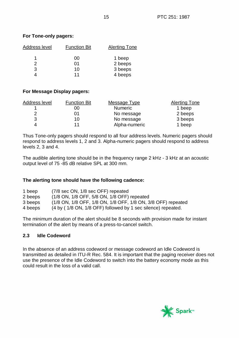
The receiver should respond to any of the paging addresses identified by the code function bits 20/21 appropriate to the type of pager and give the audible alerting tone sequence defined below:
15 PTC 251: 1987
For Tone-only pagers: Address level Function Bit Alerting Tone 1 00 1 beep 2 01 2 beeps 3 10 3 beeps 4 11 4 beeps For Message Display pagers: Address level Function Bit Message Type Alerting Tone 1 00 Numeric 1 beep 2 01 No message 2 beeps 3 10 No message 3 beeps 4 11 Alpha-numeric 1 beep Thus Tone-only pagers should respond to all four address levels. Numeric pagers should respond to address levels 1, 2 and 3. Alpha-numeric pagers should respond to address levels 2, 3 and 4. The audible alerting tone should be in the frequency range 2 kHz - 3 kHz at an acoustic output level of 75 -85 dB relative SPL at 300 mm. The alerting tone should have the following cadence: 1 beep (7/8 sec ON, 1/8 sec OFF) repeated 2 beeps (1/8 ON, 1/8 OFF, 5/8 ON, 1/8 OFF) repeated 3 beeps (1/8 ON, 1/8 OFF, 1/8 ON, 1/8 OFF, 1/8 ON, 3/8 OFF) repeated 4 beeps (4 by ( 1/8 ON, 1/8 OFF) followed by 1 sec silence) repeated. The minimum duration of the alert should be 8 seconds with provision made for instant termination of the alert by means of a press-to-cancel switch. 2.3 Idle Codeword
In the absence of an address codeword or message codeword an Idle Codeword is transmitted as detailed in ITU-R Rec. 584. It is important that the paging receiver does not use the presence of the Idle Codeword to switch into the battery economy mode as this could result in the loss of a valid call.

PTC 251: 1987 16
2.4 Synchronisation Recovery
If a receiver loses synchronisation, or if it commences receiving after the preamble has been completed, it is desirable that it can receive synchronisation on receipt of a number of valid batches. 2.5 Error Detection and Correction
The paging receiver should be capable of utilising the error detection and correction capabilities of the code. If a pager is able to correct a message codeword, this should be done without indication to the recipient. However, if an erroneous message codeword is detected but cannot be corrected, then some indication should be given, e.g. flashing display of the characters in doubt. 2.6 Message Termination
The pager should cease decoding a message when either an idle or Address Codeword is received or when two successive information codewords are indecipherable, even if they immediately follow a message indicating pager address. 2.7 Falsing Rates
The false call rate should be less than one false call per year under typical operating conditions. 2.8 Decoding Reliability
In the presence of a correctly encoded signal at a level of 10dB above the receiver sensitivity level, the receiver should have a call success rate of greater than 99.5%. 2.9 Memory Storage
The minimum message storage capacity should be 20 characters for numeric pagers and 40 characters for alpha-numeric pagers.
3. Environmental Requirements
All performance requirements should be met over the operating temperature range –10 to +40 °C with relative humidities of up to 90%.

17 PTC 251: 1987
4. Mechanical Requirements
4.1 Size and Weight
The receiver should be capable of fitting unabtrusively into a suit breast pocket. The size and weight should be minimised as far as practicable bearing in mind the cost, sensitivity and servicing criteria. 4.2 Ruggedness
The receiver should be able to withstand six random oriented drops from a height of 1.2m onto a smooth concrete surface with no more than superficial mechanical damage, and should afterwards continue to meet all performance requirements. 4.3 Battery
The battery should be of an easily obtainable type. An audible low battery level indication should be provided. The pager should continue to meet its stated specification over the battery voltage range from 10% above the nominal battery voltage level down to the voltage at which the low voltage warning is given. The method of replacing the battery should be simple and convenient to the user. Polarity markings and where possible mechanical means, should be provided to minimise the possibility of incorrectly inserting the battery. 4.4 Access to circuitry
Access to the interior of the receiver should be available only through use of a special tool.
5 Reliability
A mean time between failures of not less than four years is recommended. 6. Optional Features
The following optional features may be provided: -
(1) Dual radio identity code (2) Printer output (3) Intrinsically safe pager (4) Vibrator silent alert