Specification of I/O Hardware Abstraction...Basic Software I/O Hardware Abstraction. The I/O...
57
Specification of I/O Hardware Abstraction V3.2.0 R4.0 Rev 3 Document Title Specification of I/O Hardware Abstraction Document Owner AUTOSAR Document Responsibility AUTOSAR Document Identification No 047 Document Classification Auxiliary Document Version 3.2.0 Document Status Final Part of Release 4.0 Revision 3 Document Change History Date Version Changed by Change Description 02.11.2011 3.2.0 AUTOSAR Administration Update Version Check requirement 22.10.2010 3.1.0 AUTOSAR Administration Names of callback notification APIs have been corrected. Exported files <ModuleName>.h of underlying modules are used, instead of <ModuleName>_Types.h 30.11.2009 3.0.0 AUTOSAR Administration I/O Hardware Abstraction configuration has been removed from the EcucParamDef Functional Diagnostics' interface has been added (DCM controls I/O Signals) Unnecessary classes, attributes and types removed Legal disclaimer revised 23.06.2008 2.0.1 AUTOSAR Administration Legal disclaimer revised 13.12.2007 2.0.0 AUTOSAR Administration Auto generation of chapters 8 and 10 with the Metamodel Update of tables and some chapters of the document to stay compliant with correlated documents Document meta information extended Small layout adaptations made 14.02.2007 1.1.1 AUTOSAR Administration Various images corrected in PDFversion (printing problems) 1 of 57 Document ID 047: AUTOSAR_SWS_IOHardwareAbstraction - AUTOSAR confidential -
Transcript of Specification of I/O Hardware Abstraction...Basic Software I/O Hardware Abstraction. The I/O...
Specification of I/O Hardware Abstraction V3.2.0
R4.0 Rev 3
Document Title Specification of I/O Hardware Abstraction
Document Owner AUTOSAR Document Responsibility AUTOSAR Document Identification No 047 Document Classification Auxiliary Document Version 3.2.0 Document Status Final Part of Release 4.0 Revision 3
Document Change History Date Version Changed by Change Description 02.11.2011 3.2.0 AUTOSAR
Administration Update Version Check requirement
22.10.2010 3.1.0 AUTOSAR Administration
Names of callback notification APIs have been corrected.
Exported files <ModuleName>.h of underlying modules are used, instead of <ModuleName>_Types.h
30.11.2009 3.0.0 AUTOSAR Administration
I/O Hardware Abstraction configuration has been removed from the EcucParamDef
Functional Diagnostics' interface has been added (DCM controls I/O Signals)
Unnecessary classes, attributes and types removed
Legal disclaimer revised 23.06.2008 2.0.1 AUTOSAR
Administration Legal disclaimer revised
13.12.2007 2.0.0 AUTOSAR Administration
Auto generation of chapters 8 and 10 with the Metamodel
Update of tables and some chapters of the document to stay compliant with correlated documents
Document meta information extended Small layout adaptations made
14.02.2007 1.1.1 AUTOSAR Administration
Various images corrected in PDFversion (printing problems)
1 of 57 Document ID 047: AUTOSAR_SWS_IOHardwareAbstraction - AUTOSAR confidential -
Specification of I/O Hardware Abstraction V3.2.0
R4.0 Rev 3
Document Change History Date Version Changed by Change Description 31.01.2007 1.1.0 AUTOSAR
Administration File structure updated Traceability matrix corrected Restriction for the usage of the SWC
template Chapter about IOHWAB Runnable
concept reworked Chapter about IOHWAB description
reworked Adjustments in the configuration
chapter Legal disclaimer revised Release Notes added “Advice for users” revised “Revision Information” added
27.04.2006 1.0.0 AUTOSAR Administration
Initial Release
2 of 57 Document ID 047: AUTOSAR_SWS_IOHardwareAbstraction - AUTOSAR confidential -
Specification of I/O Hardware Abstraction V3.2.0
R4.0 Rev 3
Disclaimer This specification and the material contained in it, as released by AUTOSAR, is for the purpose of information only. AUTOSAR and the companies that have contributed to it shall not be liable for any use of the specification. The material contained in this specification is protected by copyright and other types of Intellectual Property Rights. The commercial exploitation of the material contained in this specification requires a license to such Intellectual Property Rights. This specification may be utilized or reproduced without any modification, in any form or by any means, for informational purposes only. For any other purpose, no part of the specification may be utilized or reproduced, in any form or by any means, without permission in writing from the publisher. The AUTOSAR specifications have been developed for automotive applications only. They have neither been developed, nor tested for non-automotive applications. The word AUTOSAR and the AUTOSAR logo are registered trademarks. Advice for users AUTOSAR specifications may contain exemplary items (exemplary reference models, "use cases", and/or references to exemplary technical solutions, devices, processes or software). Any such exemplary items are contained in the specifications for illustration purposes only, and they themselves are not part of the AUTOSAR Standard. Neither their presence in such specifications, nor any later documentation of AUTOSAR conformance of products actually implementing such exemplary items, imply that intellectual property rights covering such exemplary items are licensed under the same rules as applicable to the AUTOSAR Standard.
3 of 57 Document ID 047: AUTOSAR_SWS_IOHardwareAbstraction - AUTOSAR confidential -
Specification of I/O Hardware Abstraction V3.2.0
R4.0 Rev 3
Table of Contents
1 Introduction and functional overview ................................................................... 7
2 Acronyms and abbreviations ............................................................................... 8
3 Related documentation...................................................................................... 10
3.1 Input documents......................................................................................... 10 3.2 Related standards and norms .................................................................... 11
4 Constraints and assumptions ............................................................................ 12
4.1 Limitations .................................................................................................. 12 4.2 Applicability to car domains........................................................................ 12
5 Dependencies to other modules........................................................................ 13
5.1 Interface with MCAL drivers ....................................................................... 13 5.1.1 Overview ............................................................................................. 13 5.1.2 Summary of interfaces with MCAL drivers .......................................... 14
5.2 Interface with the communication drivers ................................................... 14 5.3 Interface with System Services .................................................................. 16 5.4 Interface with DCM..................................................................................... 17 5.5 File structure .............................................................................................. 17
5.5.1 Code file structure ............................................................................... 17 5.5.2 Header file structure............................................................................ 17
6 Requirements traceability .................................................................................. 20
7 Functional specification ..................................................................................... 23
7.1 Integration code ......................................................................................... 23 7.1.1 Background & Rationale ..................................................................... 23 7.1.2 Requirements for integration code implementation ............................. 23
7.2 ECU Signals Concept................................................................................. 24 7.2.1 Background & Rationale ..................................................................... 24 7.2.2 Requirements about ECU signals ....................................................... 25
7.3 Attributes .................................................................................................... 26 7.3.1 Background & Rationale ..................................................................... 26 7.3.2 Requirements about ECU signal attributes ......................................... 26
7.3.2.1 Filtering/Debouncing Attribute...................................................... 26 7.3.2.2 Age Attribute ................................................................................ 26
7.4 I/O Hardware Abstraction and Software Component Template.................. 27 7.4.1 Background & Rationale ..................................................................... 27 7.4.2 Requirements about the usage of Software Component template ...... 27
7.4.2.1 Ports concept and I/O Hardware Abstraction ............................... 27 7.4.2.2 Software Component and Runnable concept............................... 28
7.5 Scheduling concept for I/O Hardware Abstraction...................................... 28 7.5.1 Background & Rationale ..................................................................... 28 7.5.2 Requirements about I/O Hardware Abstraction Scheduling concept... 29
7.5.2.1 Operations for interfaces provided by Ports ................................. 29 7.5.2.2 Notification and/or Callback ......................................................... 29 7.5.2.3 Main function / job processing function ........................................ 30 7.5.2.4 Initialization, De-initialization and/or Callout................................. 30
4 of 57 Document ID 047: AUTOSAR_SWS_IOHardwareAbstraction - AUTOSAR confidential -
Specification of I/O Hardware Abstraction V3.2.0
R4.0 Rev 3
7.5.2.5 I/O Hardware Abstraction scheduling examples .......................... 31 7.6 Other requirements .................................................................................... 33 7.7 Error classification ...................................................................................... 33 7.8 Error detection............................................................................................ 34 7.9 Error notification ......................................................................................... 34 7.10 I/O Hardware Abstraction layer description ................................................ 34
7.10.1 Background & Rationale ..................................................................... 34 7.10.2 Requirements...................................................................................... 35
7.10.2.1 I/O Hardware Abstraction Ports definition .................................... 35 7.11 Debugging Concept.................................................................................... 35
7.11.1 Background & Rationale ..................................................................... 35 7.11.2 Requirements...................................................................................... 36
7.12 Examples ................................................................................................... 36 7.12.1 EXAMPLE 1: Use case of on-board hardware .................................... 36 7.12.2 EXAMPLE 2: Use case of failure monitoring....................................... 38 7.12.3 EXAMPLE 3: Output power stage ....................................................... 39
8 API specification................................................................................................ 42
8.1 Imported types............................................................................................ 42 8.2 Type definitions .......................................................................................... 42 8.3 Function definitions .................................................................................... 43
8.3.1 IoHwAb_Init<Init_Id>........................................................................... 43 8.3.2 IoHwAb_GetVersionInfo...................................................................... 44
8.4 Call-back notifications ................................................................................ 44 8.4.1 IoHwAb_AdcNotification<#groupID>................................................... 44 8.4.2 IoHwAb_PwmNotification<#channel> ................................................. 45 8.4.3 IoHwAb_IcuNotification<#channel> .................................................... 45 8.4.4 IoHwAb_GptNotification<#channel> ................................................... 46
8.5 Scheduled functions ................................................................................... 46 8.5.1 <Name of scheduled function>............................................................ 46
8.6 Functional Diagnostics Interface ................................................................ 47 8.6.1 IoHwAb_Dcm_<EcuSignalName> ...................................................... 47 8.6.2 IoHwAb_Dcm_Read<EcuSignalName>.............................................. 48
8.7 Expected Interfaces.................................................................................... 49 8.7.1 Mandatory Interfaces .......................................................................... 49 8.7.2 Optional Interfaces .............................................................................. 51 8.7.3 Job End Notification ............................................................................ 51
9 Sequence diagrams .......................................................................................... 52
9.1 ECU-signal provided by the I/O Hardware Abstraction (example).............. 52
10 Configuration specification............................................................................. 54
10.1 Published Information................................................................................. 54
11 Changes to Release 3 ................................................................................... 55
11.1 Deleted SWS Items.................................................................................... 55 11.2 Replaced SWS Items ................................................................................. 56 11.3 Changed SWS Items.................................................................................. 56 11.4 Added SWS Items...................................................................................... 56
12 Not applicable requirements .......................................................................... 57
5 of 57 Document ID 047: AUTOSAR_SWS_IOHardwareAbstraction - AUTOSAR confidential -
Specification of I/O Hardware Abstraction V3.2.0
R4.0 Rev 3
6 of 57 Document ID 047: AUTOSAR_SWS_IOHardwareAbstraction - AUTOSAR confidential -
Specification of I/O Hardware Abstraction V3.2.0
R4.0 Rev 3
1 Introduction and functional overview
This specification specifies the functionality and the configuration of the AUTOSAR Basic Software I/O Hardware Abstraction. The I/O Hardware Abstraction is part of the ECU Abstraction Layer. The I/O Hardware Abstraction shall not be considered as a single module, as it can be implemented as more than one module. This specification for the I/O Hardware Abstraction is not intended to standardize this module or group of modules. Instead, it is intended to be a guideline for the implementation of its functional interfaces with other modules. Aim of the I/O Hardware Abstraction is to provide access to MCAL drivers by mapping I/O Hardware Abstraction ports to ECU signals. The data provided to the software component is completely abstracted from the physical layer values. Therefore, the software component designer does not need detailed knowledge about the MCAL driver's API and the units of the physical layer values anymore. The I/O Hardware Abstraction is always an ECU specific implementation, because the requirements of the software components to the basic software have to be fitted to the features of a certain MCAL implementation. The I/O Hardware Abstraction shall provide the service for initializing the whole I/O Hardware Abstraction. The intention of this document is:
to determine which part of the Software Component template shall be used when defining an I/O Hardware Abstraction.
to explain the way to define generic ports, where ECU signals are mapped. The intention of this document is not:
to provide C-APIs to provide a specific formalization for every ECU signal, like it is done via the
standardization of functional data (body domain, powertrain, chassis domain)
7 of 57 Document ID 047: AUTOSAR_SWS_IOHardwareAbstraction - AUTOSAR confidential -
Specification of I/O Hardware Abstraction V3.2.0
R4.0 Rev 3
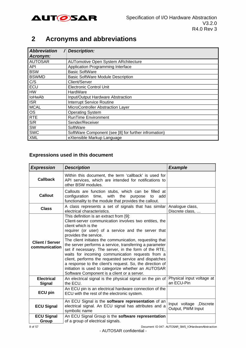
2 Acronyms and abbreviations
Abbreviation / Acronym:
Description:
AUTOSAR AUTomotive Open System ARchitecture API Application Programming Interface BSW Basic SoftWare BSWMD Basic SoftWare Module Description C/S Client/Server ECU Electronic Control Unit HW HardWare IoHwAb Input/Output Hardware Abstraction ISR Interrupt Service Routine MCAL MicroController Abstraction Layer OS Operating System RTE RunTime Environment S/R Sender/Receiver SW SoftWare SWC SoftWare Component (see [8] for further infromation) XML eXtensible Markup Language
Expressions used in this document Expression Description Example
Callback Within this document, the term ‘callback’ is used for API services, which are intended for notifications to other BSW modules.
Callouts are function stubs, which can be filled at configuration time, with the purpose to add functionality to the module that provides the callout.
Callout
Class A class represents a set of signals that has similar electrical characteristics.
Analogue class, Discrete class, …
Client / Server communication
This definition is an extract from [9]: Client-server communication involves two entities, the client which is the requirer (or user) of a service and the server that provides the service. The client initiates the communication, requesting that the server performs a service, transferring a parameter set if necessary. The server, in the form of the RTE, waits for incoming communication requests from a client, performs the requested service and dispatches a response to the client's request. So, the direction of initiation is used to categorize whether an AUTOSAR Software Component is a client or a server.
Physical input voltage at an ECU-Pin
An electrical signal is the physical signal on the pin of the ECU.
Electrical Signal
ECU pin An ECU pin is an electrical hardware connection of the ECU with the rest of the electronic system.
ECU Signal An ECU Signal is the software representation of an electrical signal. An ECU signal has attributes and a symbolic name
Input voltage ,Discrete Output, PWM Input
An ECU Signal Group is the software representation of a group of electrical signals.
ECU Signal Group
8 of 57 Document ID 047: AUTOSAR_SWS_IOHardwareAbstraction - AUTOSAR confidential -
Specification of I/O Hardware Abstraction V3.2.0
R4.0 Rev 3
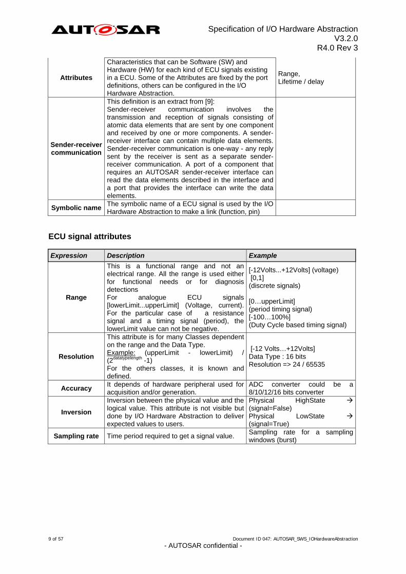
Characteristics that can be Software (SW) and Hardware (HW) for each kind of ECU signals existing in a ECU. Some of the Attributes are fixed by the port definitions, others can be configured in the I/O Hardware Abstraction.
Range, Lifetime / delay
Attributes
Sender-receiver communication
This definition is an extract from [9]: Sender-receiver communication involves the transmission and reception of signals consisting of atomic data elements that are sent by one component and received by one or more components. A sender-receiver interface can contain multiple data elements. Sender-receiver communication is one-way - any reply sent by the receiver is sent as a separate sender-receiver communication. A port of a component that requires an AUTOSAR sender-receiver interface can read the data elements described in the interface and a port that provides the interface can write the data elements.
Symbolic name The symbolic name of a ECU signal is used by the I/O Hardware Abstraction to make a link (function, pin)
ECU signal attributes
Expression Description Example
Range
This is a functional range and not an electrical range. All the range is used either for functional needs or for diagnosis detections
[-12Volts...+12Volts] (voltage) [0,1] (discrete signals)
For analogue ECU signals [lowerLimit...upperLimit] (Voltage, current). For the particular case of a resistance signal and a timing signal (period), the lowerLimit value can not be negative.
[0…upperLimit] (period timing signal) [-100…100%] (Duty Cycle based timing signal)
Resolution
This attribute is for many Classes dependent on the range and the Data Type. Example: (upperLimit - lowerLimit) / (2datatypelength -1) For the others classes, it is known and defined.
[-12 Volts…+12Volts] Data Type : 16 bits Resolution => 24 / 65535
Accuracy It depends of hardware peripheral used for acquisition and/or generation.
ADC converter could be a 8/10/12/16 bits converter
Inversion
Inversion between the physical value and the logical value. This attribute is not visible but done by I/O Hardware Abstraction to deliver expected values to users.
Physical HighState (signal=False) Physical LowState (signal=True)
Sampling rate Time period required to get a signal value. Sampling rate for a sampling windows (burst)
9 of 57 Document ID 047: AUTOSAR_SWS_IOHardwareAbstraction - AUTOSAR confidential -
Specification of I/O Hardware Abstraction V3.2.0
R4.0 Rev 3
3 Related documentation
3.1 Input documents
[1] List of Basic Software Modules AUTOSAR_TR_BSWModuleList.pdf [2] Layered Software Architecture AUTOSAR_EXP_LayeredSoftwareArchitecture.pdf [3] General Requirements on Basic Software Modules AUTOSAR_SRS_BSWGeneral.pdf [4] Specification of ECU Configuration AUTOSAR_TPS_ECUConfiguration.pdf [5] Glossary AUTOSAR_TR_Glossary.pdf [6] General Requirements on SPA AUTOSAR_SRS_SPALGeneral.pdf [7] Requirements on I/O Hardware Abstraction AUTOSAR_SRS_IOHWAbstraction.pdf [8] Software Component Template AUTOSAR_TPS_SoftwareComponentTemplate.pdf [9] Specification of RTE Software AUTOSAR_SWS_RTE.pdf [10] Specification of ECU State Manager AUTOSAR_SWS_ECUStateManager.pdf [11] Specification of ECU Resource Template AUTOSAR_TPS_ECUResourceTemplate.pdf [12] Specification of ADC Driver AUTOSAR_SWS_ADCDriver.pdf [13] Specification of DIO Driver AUTOSAR_SWS_DIODriver.pdf [14] Specification of ICU Driver AUTOSAR_SWS_ICUDriver.pdf [15] Specification of PWM Driver AUTOSAR_SWS_PWMDriver.pdf
10 of 57 Document ID 047: AUTOSAR_SWS_IOHardwareAbstraction - AUTOSAR confidential -
Specification of I/O Hardware Abstraction V3.2.0
R4.0 Rev 3
[16] Specification of PORT Driver AUTOSAR_SWS_PORTDriver.pdf [17] Specification of GPT Driver AUTOSAR_SWS_GPTDriver.pdf [18] Specification of SPI Handler/Driver AUTOSAR_SWS_SPIHandlerDriver.pdf [19] Basic Software Module Description Template AUTOSAR_TPS_BSWModuleDescriptionTemplate.pdf [20] Specification of Standard Types AUTOSAR_SWS_StandardTypes.pdf
3.2 Related standards and norms
None
11 of 57 Document ID 047: AUTOSAR_SWS_IOHardwareAbstraction - AUTOSAR confidential -
Specification of I/O Hardware Abstraction V3.2.0
R4.0 Rev 3
4 Constraints and assumptions
4.1 Limitations
No limitations
4.2 Applicability to car domains
No restrictions
12 of 57 Document ID 047: AUTOSAR_SWS_IOHardwareAbstraction - AUTOSAR confidential -
Specification of I/O Hardware Abstraction V3.2.0
R4.0 Rev 3
5 Dependencies to other modules
5.1 Interface with MCAL drivers
5.1.1 Overview
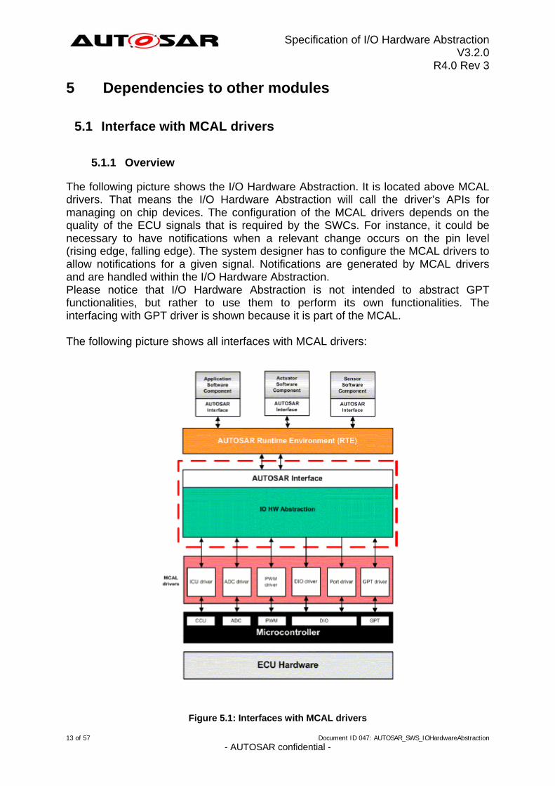
The following picture shows the I/O Hardware Abstraction. It is located above MCAL drivers. That means the I/O Hardware Abstraction will call the driver’s APIs for managing on chip devices. The configuration of the MCAL drivers depends on the quality of the ECU signals that is required by the SWCs. For instance, it could be necessary to have notifications when a relevant change occurs on the pin level (rising edge, falling edge). The system designer has to configure the MCAL drivers to allow notifications for a given signal. Notifications are generated by MCAL drivers and are handled within the I/O Hardware Abstraction. Please notice that I/O Hardware Abstraction is not intended to abstract GPT functionalities, but rather to use them to perform its own functionalities. The interfacing with GPT driver is shown because it is part of the MCAL. The following picture shows all interfaces with MCAL drivers:
Figure 5.1: Interfaces with MCAL drivers
13 of 57 Document ID 047: AUTOSAR_SWS_IOHardwareAbstraction - AUTOSAR confidential -
Specification of I/O Hardware Abstraction V3.2.0
R4.0 Rev 3
5.1.2 Summary of interfaces with MCAL drivers
[IoHwAb078] ⌈The I/O Hardware Abstraction implementation shall provide Software
Components with access to all MCAL drivers.⌋ (BSW00384) MCAL drivers
IoHwAb ADC driver PWM driver
PORT driver
ICU driver DIO driver GPT driver
Calls API of X X X X X X
Receives notifications from
X X X - - X
The table above must be read as following:
The I/O Hardware Abstraction calls API of the ADC driver The I/O Hardware Abstraction receives notifications from the ADC driver. The I/O Hardware Abstraction does not receive notifications from the DIO
driver. A complete list of all APIs is given in chapter 8.7.1
5.2 Interface with the communication drivers
[IoHwAb079] ⌈The I/O Hardware Abstraction implementation shall provide Software Components with access to communication drivers (for instance by SPI), if on-board
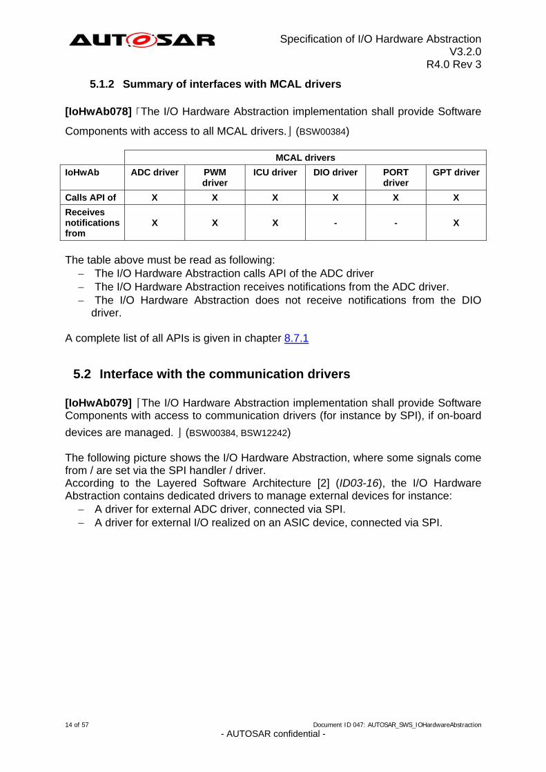
devices are managed. ⌋ (BSW00384, BSW12242) The following picture shows the I/O Hardware Abstraction, where some signals come from / are set via the SPI handler / driver. According to the Layered Software Architecture [2] (ID03-16), the I/O Hardware Abstraction contains dedicated drivers to manage external devices for instance:
A driver for external ADC driver, connected via SPI. A driver for external I/O realized on an ASIC device, connected via SPI.
14 of 57 Document ID 047: AUTOSAR_SWS_IOHardwareAbstraction - AUTOSAR confidential -
Specification of I/O Hardware Abstraction V3.2.0
R4.0 Rev 3
Figure 5.2: Interfaces with communication drivers
15 of 57 Document ID 047: AUTOSAR_SWS_IOHardwareAbstraction - AUTOSAR confidential -
Specification of I/O Hardware Abstraction V3.2.0
R4.0 Rev 3
5.3 Interface with System Services
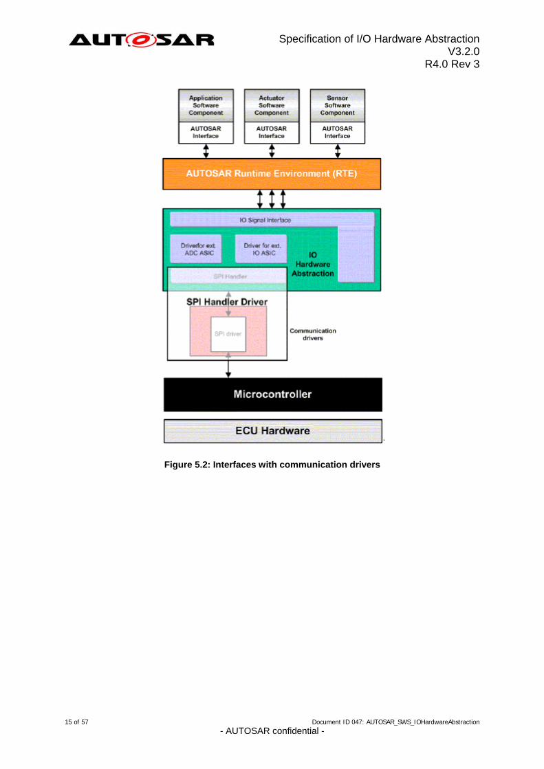
[IoHwAb044] ⌈The I/O Hardware Abstraction implementation shall interface with the following system services:
ECU State Manager (init function) DEM: Diagnostic Event Manager DET: Development Error Tracer
BSW Scheduler⌋ (BSW00336, BSW00384, BSW101)
Figure 5.3: Interfaces with system services
16 of 57 Document ID 047: AUTOSAR_SWS_IOHardwareAbstraction - AUTOSAR confidential -
Specification of I/O Hardware Abstraction V3.2.0
R4.0 Rev 3
5.4 Interface with DCM
The I/O Hardware Abstraction shall provide interfaces to DCM, for functional diagnostics of the software components. DCM will use functional diagnostics for reading and controlling the implemented ECU signals. The prototypes of the interfaces provided to DCM shall be within a header file IoHwAb_<ServiceComponentName_>Dcm.h, for each ServiceComponent. For details of the interfaces, refer Section 8.6.
5.5 File structure
5.5.1 Code file structure
[IoHwAb097] ⌈The code file structure shall not be defined within this specification. ⌋ (BSW158)
5.5.2 Header file structure
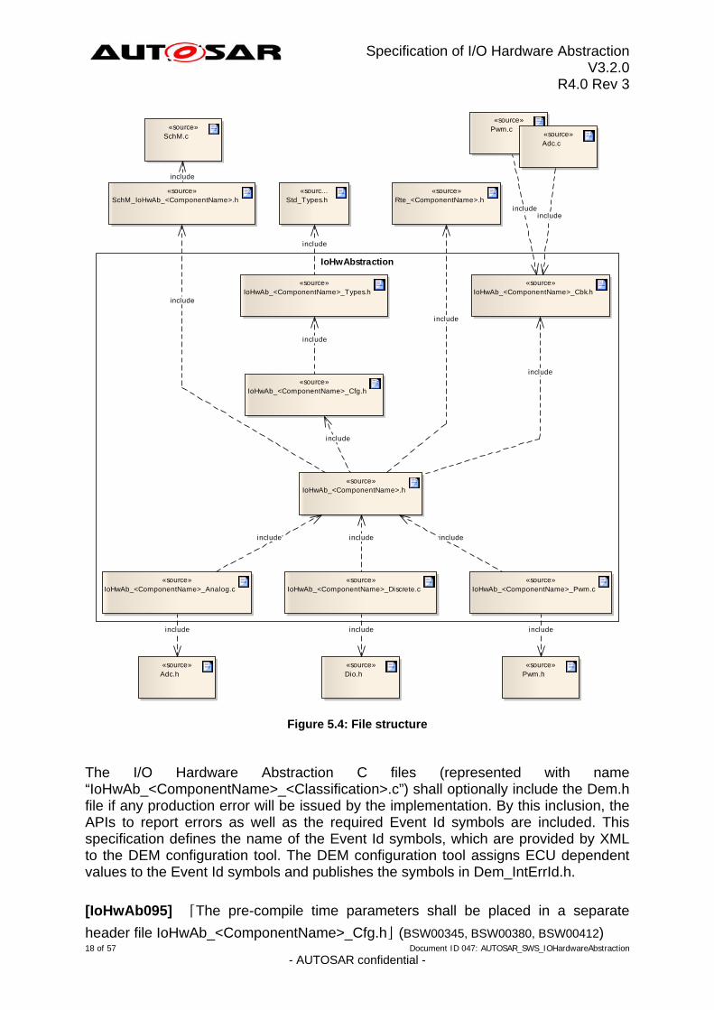
As there can be multiple, project-specific instances of the I/O Hardware Abstraction, the file structure cannot be specified. Figure 5.4 gives an example of an I/O Hardware Abstraction that has its ECU signals categorized in three modules (the partitioning of the signals into separate modules is implementation-specific):
17 of 57 Document ID 047: AUTOSAR_SWS_IOHardwareAbstraction - AUTOSAR confidential -
Specification of I/O Hardware Abstraction V3.2.0
R4.0 Rev 3
IoHwAbstraction
«source»IoHwAb_<ComponentName>_Cfg.h
«source»IoHwAb_<ComponentName>.h
«sourIoHwAb_<Component
ce»Name>_Cbk.h
«sIoHwAb_<Component
ource»Name>_Analog.c
«source»IoHwAb_<ComponentName>_Discrete.c
«sourIoHwAb_<Component
ce»Name>_Pwm.c
«source»IoHwAb_<ComponentName>_Types.h
«sSchM_IoHwAb_<C
ource»omponentName>.h
«sSc
ource»hM.c
«sourc...Std_Types.h
«source»Rte_<ComponentName>.h
«source»Pwm.c
«source»Adc.c
includeinclude
include
include
include
include
«source»Adc.h
«source»Dio.h
«source»Pwm.h
include
include include include
include include include
include
include
Figure 5.4: File structure
The I/O Hardware Abstraction C files (represented with name “IoHwAb_<ComponentName>_<Classification>.c”) shall optionally include the Dem.h file if any production error will be issued by the implementation. By this inclusion, the APIs to report errors as well as the required Event Id symbols are included. This specification defines the name of the Event Id symbols, which are provided by XML to the DEM configuration tool. The DEM configuration tool assigns ECU dependent values to the Event Id symbols and publishes the symbols in Dem_IntErrId.h.
18 of 57 Document ID 047: AUTOSAR_SWS_IOHardwareAbstraction - AUTOSAR confidential -
[IoHwAb095] ⌈The pre-compile time parameters shall be placed in a separate
header file IoHwAb_<ComponentName>_Cfg.h⌋ (BSW00345, BSW00380, BSW00412)
Specification of I/O Hardware Abstraction V3.2.0
R4.0 Rev 3
The I/O Hardware Abstraction should be considered as a set of modules. It could be designed as more than one module-source and header file. This document does not specify a standard naming scheme.
[IoHwAb112] ⌈File names should be prefixed with ‘IoHwAb_<ComponentName>_<reference>’ (where the field <reference> can be an implementation-specific category and the field <ComponentName> is the name of the atomic software component, i.e. the instance of the I/O Hardware Abstraction) in
order to avoid name clashes. ⌋ ( )
19 of 57 Document ID 047: AUTOSAR_SWS_IOHardwareAbstraction - AUTOSAR confidential -
Specification of I/O Hardware Abstraction V3.2.0
R4.0 Rev 3
6 Requirements traceability
Requirement Satisfied by
- IoHwAb025
- IoHwAb037
- IoHwAb112
- IoHwAb105
- IoHwAb070
- IoHwAb119
- IoHwAb133
- IoHwAb063
- IoHwAb121
- IoHwAb104
- IoHwAb106
- IoHwAb120
- IoHwAb132
- IoHwAb021
- IoHwAb068
- IoHwAb131
- IoHwAb075
- IoHwAb069
- IoHwAb122
- IoHwAb123
- IoHwAb130
- IoHwAb124
- IoHwAb019
- IoHwAb107
BSW00300 IoHwAb145
BSW00321 IoHwAb145
BSW00323 IoHwAb067
BSW00325 IoHwAb145
BSW00326 IoHwAb145
BSW00329 IoHwAb145
BSW00333 IoHwAb033
BSW00334 IoHwAb145
BSW00336 IoHwAb036, IoHwAb044
BSW00337 IoHwAb067
BSW00338 IoHwAb051
BSW00339 IoHwAb052, IoHwAb055
BSW00341 IoHwAb145
BSW00342 IoHwAb145
20 of 57 Document ID 047: AUTOSAR_SWS_IOHardwareAbstraction - AUTOSAR confidential -
Specification of I/O Hardware Abstraction V3.2.0
R4.0 Rev 3
BSW00343 IoHwAb145
BSW00345 IoHwAb095
BSW00350 IoHwAb053
BSW00369 IoHwAb054
BSW00376 IoHwAb145
BSW00380 IoHwAb095
BSW00384 IoHwAb079, IoHwAb078, IoHwAb044
BSW00385 IoHwAb051
BSW00398 IoHwAb145
BSW00399 IoHwAb145
BSW004 IoHwAb066
BSW00400 IoHwAb145
BSW00404 IoHwAb145
BSW00405 IoHwAb145
BSW00407 IoHwAb058, IoHwAb057
BSW00411 IoHwAb058
BSW00412 IoHwAb095
BSW00416 IoHwAb145
BSW00417 IoHwAb145
BSW00423 IoHwAb001
BSW00424 IoHwAb145
BSW00428 IoHwAb145
BSW00432 IoHwAb145
BSW00439 IoHwAb145
BSW00440 IoHwAb143
BSW00441 IoHwAb102
BSW00450 IoHwAb035
BSW005 IoHwAb145
BSW007 IoHwAb145
BSW07500002 IoHwAb136, IoHwAb137, IoHwAb135, IoHwAb139, IoHwAb138, IoHwAb140, IoHwAb141, IoHwAb142
BSW101 IoHwAb059, IoHwAb061, IoHwAb060, IoHwAb036, IoHwAb044
BSW12056 IoHwAb033, IoHwAb034, IoHwAb032
BSW12057 IoHwAb145
BSW12063 IoHwAb145
BSW12064 IoHwAb145
BSW12067 IoHwAb145
BSW12068 IoHwAb145
BSW12069 IoHwAb145
BSW12075 IoHwAb145
BSW12077 IoHwAb145
BSW12078 IoHwAb145
21 of 57 Document ID 047: AUTOSAR_SWS_IOHardwareAbstraction - AUTOSAR confidential -
Specification of I/O Hardware Abstraction V3.2.0
R4.0 Rev 3
BSW12092 IoHwAb145
BSW12125 IoHwAb145
BSW12129 IoHwAb145
BSW12163 IoHwAb145
BSW12169 IoHwAb145
BSW12242 IoHwAb079
BSW12248 IoHwAb038
BSW12263 IoHwAb145
BSW12264 IoHwAb145
BSW12265 IoHwAb145
BSW12267 IoHwAb145
BSW12448 IoHwAb051, IoHwAb054
BSW12451 IoHwAb039
BSW12461 IoHwAb145
BSW12462 IoHwAb145
BSW12463 IoHwAb145
BSW157 IoHwAb145
BSW158 IoHwAb097
BSW160 IoHwAb145
BSW161 IoHwAb145
BSW162 IoHwAb145
BSW164 IoHwAb145
BSW167 IoHwAb145
BSW168 IoHwAb145
BSW170 IoHwAb145
BSW171 IoHwAb053
22 of 57 Document ID 047: AUTOSAR_SWS_IOHardwareAbstraction - AUTOSAR confidential -
Specification of I/O Hardware Abstraction V3.2.0
R4.0 Rev 3
7 Functional specification
7.1 Integration code
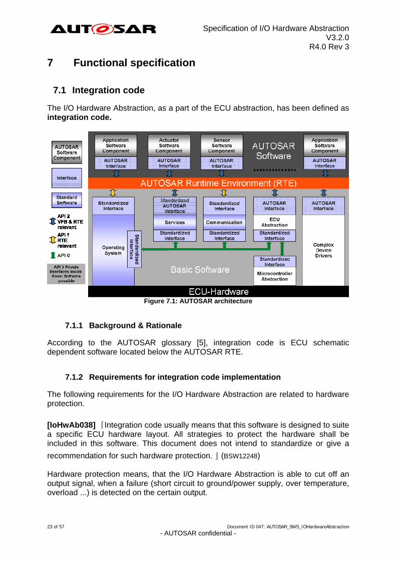
The I/O Hardware Abstraction, as a part of the ECU abstraction, has been defined as integration code.
Figure 7.1: AUTOSAR architecture
7.1.1 Background & Rationale
According to the AUTOSAR glossary [5], integration code is ECU schematic dependent software located below the AUTOSAR RTE.
7.1.2 Requirements for integration code implementation
The following requirements for the I/O Hardware Abstraction are related to hardware protection.
[IoHwAb038] ⌈Integration code usually means that this software is designed to suite a specific ECU hardware layout. All strategies to protect the hardware shall be included in this software. This document does not intend to standardize or give a
recommendation for such hardware protection. ⌋ (BSW12248) Hardware protection means, that the I/O Hardware Abstraction is able to cut off an output signal, when a failure (short circuit to ground/power supply, over temperature, overload ...) is detected on the certain output.
23 of 57 Document ID 047: AUTOSAR_SWS_IOHardwareAbstraction - AUTOSAR confidential -
Specification of I/O Hardware Abstraction V3.2.0
R4.0 Rev 3
[IoHwAb039] ⌈The I/O Hardware Abstraction shall not contain strategies for failure
recovery. Failure recovery actions can only be decided by the responsible SWC. ⌋ (BSW12451) The internal behavior of the I/O Hardware Abstraction is project-specific and cannot be standardized. There is no I/O Hardware Abstraction scalability. The SWC specifies what is needed (quality of signal) and the I/O Hardware Abstraction has to provide it.
7.2 ECU Signals Concept
7.2.1 Background & Rationale
The I/O Hardware Abstraction cannot provide Standardized AUTOSAR Interfaces to AUTOSAR SW-Cs, as its interfaces to the upper layer strongly depend on the chain of signal acquisition. Instead, the I/O Hardware Abstraction provides AUTOSAR Interfaces. These AUTOSAR Interfaces represent an abstraction of electrical signals coming from the ECU inputs / addressed to ECU outputs. Alternatively, these electrical signals may also come from other ECUs or be addressed to other ECUs (e.g. via a CAN network). Ports are entry points of AUTOSAR components. They are typified by an AUTOSAR interface. These interfaces correspond to “ECU signals”. The concept of ECU signals comes from the necessity to guarantee the interchangeability of hardware platforms.
24 of 57 Document ID 047: AUTOSAR_SWS_IOHardwareAbstraction - AUTOSAR confidential -
Specification of I/O Hardware Abstraction V3.2.0
R4.0 Rev 3
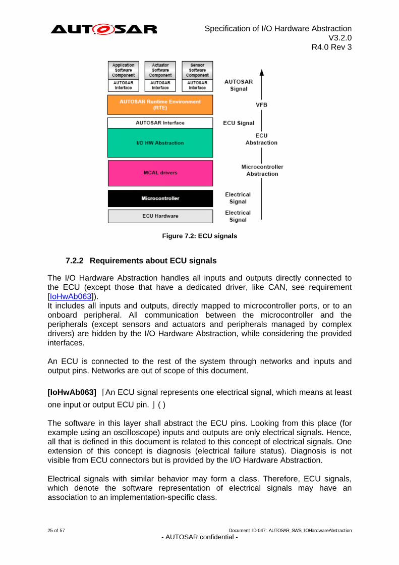
Figure 7.2: ECU signals
7.2.2 Requirements about ECU signals
The I/O Hardware Abstraction handles all inputs and outputs directly connected to the ECU (except those that have a dedicated driver, like CAN, see requirement [IoHwAb063]). It includes all inputs and outputs, directly mapped to microcontroller ports, or to an onboard peripheral. All communication between the microcontroller and the peripherals (except sensors and actuators and peripherals managed by complex drivers) are hidden by the I/O Hardware Abstraction, while considering the provided interfaces. An ECU is connected to the rest of the system through networks and inputs and output pins. Networks are out of scope of this document.
[IoHwAb063] ⌈An ECU signal represents one electrical signal, which means at least
one input or output ECU pin. ⌋ ( ) The software in this layer shall abstract the ECU pins. Looking from this place (for example using an oscilloscope) inputs and outputs are only electrical signals. Hence, all that is defined in this document is related to this concept of electrical signals. One extension of this concept is diagnosis (electrical failure status). Diagnosis is not visible from ECU connectors but is provided by the I/O Hardware Abstraction. Electrical signals with similar behavior may form a class. Therefore, ECU signals, which denote the software representation of electrical signals may have an association to an implementation-specific class.
25 of 57 Document ID 047: AUTOSAR_SWS_IOHardwareAbstraction - AUTOSAR confidential -
Specification of I/O Hardware Abstraction V3.2.0
R4.0 Rev 3
7.3 Attributes
7.3.1 Background & Rationale
Even though most of the characteristics of each ECU Signal are defined by the SWC, some properties have to be added to each signal to provide the signal quality the SWC expects.
7.3.2 Requirements about ECU signal attributes
To detail the chain of signal-acquisition, a list of Attributes is defined to identify configurable characteristics of ECU signals.
7.3.2.1 Filtering/Debouncing Attribute
[IoHwAb019] ⌈All ECU Signals shall have a Filtering/Debounce Attribute, so that the captured ‘raw’- values can be filtered or debounced before passing them to the upper layer. This attribute is only reasonable for input signals. It influences the
implementation of acquisition and access to the signal values. ⌋ ( )
7.3.2.2 Age Attribute
All ECU signals handled by I/O Hardware Abstraction depend on the ECU hardware design. This means that the time to set ECU Output signals and the time to get ECU Input signals could be different from one to other ECU signal. So to guarantee a template behavior for all kind of ECU signals (Input / Output) a common Age Attribute is defined and it shall be configured for each ECU signal.
[IoHwAb021] ⌈All ECU signals shall have an Age Attribute. The Age Attribute has two specific names according to the direction of ECU signal (Input / Output). Anyway, it always contains a maximum time value. Following descriptions explain the meaning of this Attribute for each kind of ECU signals.
ECU Input signals: the specific functionality of this attribute is to limit the signals lifetime. The value defines the maximum allowed age for data of this signal. If the lifetime is 0, the signal has to be retrieved from the physical register, immediately. If the lifetime is greater than 0, the signal is valid for the specified time.
ECU Output signals: the specific functionality of this attribute is to limit the signal output to a maximum delay. The value defines the maximum allowed time until this signal is actually set. If delay is 0, then the signal has to be set to the physical register, immediately. If the delay is greater than 0, the signal
can be set until the configured time has elapsed. ⌋ ( )
26 of 57 Document ID 047: AUTOSAR_SWS_IOHardwareAbstraction - AUTOSAR confidential -
Specification of I/O Hardware Abstraction V3.2.0
R4.0 Rev 3
7.4 I/O Hardware Abstraction and Software Component Template
Note about this chapter: This chapter refers to document [8]. Changes inside this document may influence the content of this chapter.
7.4.1 Background & Rationale
This approach allows defining the standardization deepness. As explained previously, the implementation is integration code. Therefore, this chapter only summarizes how to define the I/O Hardware Abstraction as a Software Component (SWC), and gives a short overview of the internal behavior. The internal behavior description mainly covers BSW scheduling mechanisms.
7.4.2 Requirements about the usage of Software Component template
[IoHwAb001] ⌈The I/O Hardware Abstraction shall be based upon the Software
Component Template as specified in document [8]. ⌋ (BSW00423) In the same manner as in any other Software Component, the I/O Hardware Abstraction might be sub-structured, depending on the complexity of an ECU. Indeed, the I/O Hardware Abstraction is a classical Component Prototype, that can be atomic or composed and that provides and requires interfaces. Moreover, I/O Hardware Abstraction may only interact by means of their PortPrototypes with other Software Components above the RTE. Hidden dependencies that are not expressed by means of PortPrototypes are not allowed. However, the I/O Hardware Abstraction interfaces on one side the MCAL drivers via
Standardized Interfaces and on the other side the RTE. Hence, I/O Hardware Abstraction shall respect the virtual ports concept.
[IoHwAb025] ⌈The I/O Hardware Abstraction shall be implemented as one or more
instances of the EcuAbstractionComponentType. ⌋ ( ) See [8] for further information about the EcuAbstractionComponentType. An instantiation of EcuAbstractionComponentType provides a set of ports. During RTE Generation, only those that are connected with Software Components are taken into account. This chapter gives an overview of the virtual ports concept and runnable entities applied to the I/O Hardware Abstraction needs. The following chapters of this document describe the points set out here in more detail.
7.4.2.1 Ports concept and I/O Hardware Abstraction
This is an overview of recommendations for defining Ports of I/O Hardware Abstraction using the Software Component template. 27 of 57 Document ID 047: AUTOSAR_SWS_IOHardwareAbstraction
- AUTOSAR confidential -
Specification of I/O Hardware Abstraction V3.2.0
R4.0 Rev 3
Further chapters in this document go deeper in usage of ports for I/O
Hardware Abstraction. Nevertheless, it is advised to read the Software Component Template document [8] to be aware of all terms and all concepts used.
The attributes described in chapter 7.3 shall be defined by annotating the ports of the I/O Hardware Abstraction components with an IoHwAbstractionServerAnnotation (see [8]).
7.4.2.2 Software Component and Runnable concept
Software Components have functions to realize their strategies and internal behaviors. These are partly described using runnable entities. The former is contained in runnables and the latter depends of runnables design. Runnable entities are provided by the Atomic Software Component and are (at least indirectly) a subject for scheduling by the underlying operating system. An implementation of an atomic Software Component has to provide an entry-point to code for each Runnable in its "InternalBehavior". For more information, please refer to the specification [8]. The runnable entities are the smallest code-fragments, which can be activated independently. They are provided by the Atomic Software Component and are activated by the RTE. Runnables are for instance set up to respond to data exchange or operation invocation on a server. The runnable entities have three possible states: Suspended, Enabled and Running. During run-time, each runnable of an atomic Software Component is (by being a member of an OS task) in one of these states. For a sight of available choices and attributes to define each runnables of the Atomic Software Component, please refer to specification [8].
7.5 Scheduling concept for I/O Hardware Abstraction
7.5.1 Background & Rationale
The I/O Hardware Abstraction may consist of several BSW modules (e.g. onboard device driver). Each of these BSW modules can provide BSW runnable entities (also called BswModuleEntity in the RTE Specification (see [9]). To make a parallel, a BswModuleEntity is the equivalent of SWC runnable entities, for which the AUTOSAR glossary [5] gives the following definition: „”A Runnable Entity is a part of an Atomic Software-Component ( definition) which can be executed and scheduled independently from the other Runnable Entities of this Atomic Software-Component“.
28 of 57 Document ID 047: AUTOSAR_SWS_IOHardwareAbstraction - AUTOSAR confidential -
Specification of I/O Hardware Abstraction V3.2.0
R4.0 Rev 3
This means that the I/O Hardware Abstraction can use Runnable Scheduling and BSW Scheduling simultaneously. The Runnable Scheduling handles the Runnable Entities and is mandatory. Unlike the Runnable Scheduling, the BSW Scheduling is optional and the interfacing with the BSW Scheduler has to be done manually. In case of SWC runnable entities, these are called in AUTOSAR OS Tasks bodies. Runnables are given in the SWC description. Activation of SWC runnables strongly depends on RTE events. In the same way than SWCs are most often activated by RTEEvents, the schedulables BswModuleEntities can be activated by BswEvents. There is also a kind of BswModuleEntity which can be activated in interrupt context. This leads to two sub-classes: BswSchedulableEntity and BswInterruptEntity.
7.5.2 Requirements about I/O Hardware Abstraction Scheduling concept
7.5.2.1 Operations for interfaces provided by Ports
The I/O Hardware Abstraction, described from the interfaces point of view, implements the counterpart of the PortInterfaces defined by the SW-C, i.e. it provides Runnable Entities that implement the Provide Ports (Server port, Sender/Receiver port) required by the SW-C.
[IoHwAb068] ⌈The implementation behind the service of the I/O Hardware Abstraction's Provide Ports is ECU specific and the mapping to the corresponding
“PortInterface” shall be documented in the Software Component description. ⌋ ( )
7.5.2.1.1 Get operation, OP_GET
[IoHwAb069] ⌈For an ECU Signal associated with a PortInterface configured as an
input signal, the I/O Hardware Abstraction shall provide an OP_GET operation. ⌋ ( )
7.5.2.1.2 Set operation, OP_SET
[IoHwAb070] ⌈For an ECU Signal associated with a PortInterface configured as an
output signal, the I/O Hardware Abstraction shall provide an OP_SET operation. ⌋ ( )
7.5.2.2 Notification and/or Callback
[IoHwAb032] ⌈The I/O Hardware Abstraction shall define BswInterruptEntities (a sub-class class of BswModuleEntity by opposition to BswSchedulableEntity) to fulfill notification and/or callback mechanisms to exchange data with other modules below
the RTE within an interrupt context. ⌋ (BSW12056)
29 of 57 Document ID 047: AUTOSAR_SWS_IOHardwareAbstraction - AUTOSAR confidential -
Specification of I/O Hardware Abstraction V3.2.0
R4.0 Rev 3
The I/O Hardware Abstraction may contain one or several callback functions. The available callback functions need to be hooked up to the notification interfaces of the MCAL drivers. Therefore, they have to respect the prototype definition of the MCAL drivers (no passing parameter, no return parameter).
[IoHwAb033] ⌈The implementation has to take into consideration, that the callback
functions will be executed in interrupt context. ⌋ (BSW00333, BSW12056) Callback functions can additionally provide the capability to trigger Software Components outside of the I/O Hardware Abstraction. These notifications need to be handled through the RTE (sender port).
[IoHwAb034] ⌈The number of available callback functions and the order of execution will be implementation dependent and must be documented in the I/O Hardware
Abstraction BSWMD. ⌋ (BSW12056)
[IoHwAb143] ⌈The function prototype for the callback function functions of the I/O Hardware Abstraction which are routed via RTE shall be implemented according to
the following rule: StdReturnType Rte_Call_<p>_<o>(<parameters>)⌋ (BSW00440) The callback functions have to be to be compatible to Rte_Call_<p>_<o> API of the RTE to enable a type safe configuration and implementation of AUTOSAR Services and IO Hardware Abstraction.
7.5.2.3 Main function / job processing function
[IoHwAb035] ⌈The I/O Hardware Abstraction may contain one or several job processing functions that are BswSchedulableEntities (a sub-class of BswModuleEntity by opposition to BswInterruptEntity, e.g. one for each device driver). They shall be activated according to their use. They will be time-triggered by the BSW Scheduler. They could be synchronized to the execution of the other runnable entities. The number of BswSchedulableEntities and their order of execution will be implementation dependent and must be documented in the I/O Hardware Abstraction
description. ⌋ (BSW00450)
7.5.2.4 Initialization, De-initialization and/or Callout
[IoHwAb036] ⌈The I/O Hardware Abstraction shall define BswModuleEntries to exchange data with other software below the RTE outside interrupt context, for
example in case of BSW initialization/de-initialization. ⌋ (BSW00336, BSW101) These BswModuleEntries are linked to a dedicated BswModuleEntity, which will be called to perform the service / exchange the data. 30 of 57 Document ID 047: AUTOSAR_SWS_IOHardwareAbstraction
- AUTOSAR confidential -
Specification of I/O Hardware Abstraction V3.2.0
R4.0 Rev 3
The I/O Hardware Abstraction may contain one or several initialization and de-initialization functions (e.g. one for each device driver). Similar to the MCAL drivers the initialization functions shall contain a parameter to be able to pass different configurations to the device drivers. This function shall initialize all local and global variables used by the I/O Hardware Abstraction driver to an initial state.
[IoHwAb037] ⌈The initialization/de-initialization functions shall be used/handled by the ECU State Manager, exclusively. For more information, refer to [10]. The number of available functions and the order of execution are implementation-
dependent and must be documented in the I/O Hardware Abstraction description. ⌋ ( )
7.5.2.5 I/O Hardware Abstraction scheduling examples
7.5.2.5.1 Interface provided by ADC and I/O Hardware Abstraction
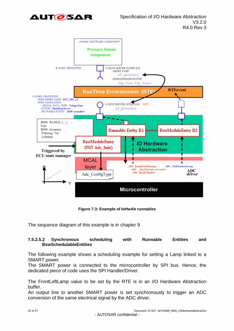
The following example shows a scheduling example for an ADC conversion. The I/O Hardware Abstraction shall provide two P-ports. The Software Component interface in this example is af_pressure. The ECU state manager is able to trigger a BswModuleEntry for initialization of the ADC driver (Call of Adc_Init() with the Adc_ConfigType structure). Use Case: The software component needs the af_pressure value. 1 – RTE triggers the OP_GET operation of the dedicated P-Port. 2 – R1 is a runnable entity and it allows to call the appropriated ADC driver services
ADC_EnableNotification ADC_StartGroupConversion
3 – At the end of conversion, the ADC triggers the BswModuleEntry R2, within interrupt context. This is possible since the notification is allowed for this interface. The ADC_NotificationGroup() function is specified in the ADC driver 4 – The notification is then “sent” to the Software Component via a RTEevent.
31 of 57 Document ID 047: AUTOSAR_SWS_IOHardwareAbstraction - AUTOSAR confidential -
Specification of I/O Hardware Abstraction V3.2.0
R4.0 Rev 3
Figure 7.3: Example of IoHwAb runnables The sequence diagram of this example is in chapter 9
7.5.2.5.2 Synchronous scheduling with Runnable Entities and BswSchedulableEntities
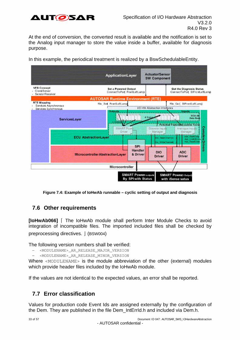
The following example shows a scheduling example for setting a Lamp linked to a SMART power. The SMART power is connected to the microcontroller by SPI bus. Hence, the dedicated piece of code uses the SPI Handler/Driver. The FrontLeftLamp value to be set by the RTE is in an I/O Hardware Abstraction buffer. An output line to another SMART power is set synchronously to trigger an ADC conversion of the same electrical signal by the ADC driver.
32 of 57 Document ID 047: AUTOSAR_SWS_IOHardwareAbstraction - AUTOSAR confidential -
Specification of I/O Hardware Abstraction V3.2.0
R4.0 Rev 3
At the end of conversion, the converted result is available and the notification is set to the Analog input manager to store the value inside a buffer, available for diagnosis purpose. In this example, the periodical treatment is realized by a BswSchedulableEntity.
Figure 7.4: Example of IoHwAb runnable – cyclic setting of output and diagnosis
7.6 Other requirements
[IoHwAb066] ⌈ The IoHwAb module shall perform Inter Module Checks to avoid integration of incompatible files. The imported included files shall be checked by
preprocessing directives. ⌋ (BSW004) The following version numbers shall be verified: <MODULENAME>_AR_RELEASE_MAJOR_VERSION <MODULENAME>_AR_RELEASE_MINOR_VERSION
Where <MODULENAME> is the module abbreviation of the other (external) modules which provide header files included by the IoHwAb module. If the values are not identical to the expected values, an error shall be reported.
7.7 Error classification
Values for production code Event Ids are assigned externally by the configuration of the Dem. They are published in the file Dem_IntErrId.h and included via Dem.h.
33 of 57 Document ID 047: AUTOSAR_SWS_IOHardwareAbstraction - AUTOSAR confidential -
Specification of I/O Hardware Abstraction V3.2.0
R4.0 Rev 3
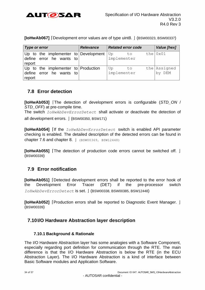
[IoHwAb067] ⌈Development error values are of type uint8. ⌋ (BSW00323, BSW00337) Type or error Relevance Related error code Value [hex]
Up to the implementer
0x01 Up to the implementer to define error he wants to report
Development
Up to the implementer
Assigned by DEM
Up to the implementer to define error he wants to report
Production
7.8 Error detection
[IoHwAb053] ⌈The detection of development errors is configurable (STD_ON / STD_OFF) at pre-compile time. The switch IoHwAbDevErrorDetect shall activate or deactivate the detection of
all development errors. ⌋ (BSW00350, BSW171)
[IoHwAb054] ⌈If the IoHwAbDevErrorDetect switch is enabled API parameter checking is enabled. The detailed description of the detected errors can be found in chapter 7.6 and chapter 8. ⌋ (BSW00369, BSW12448)
[IoHwAb055] ⌈The detection of production code errors cannot be switched off. ⌋ (BSW00339)
7.9 Error notification
[IoHwAb051] ⌈Detected development errors shall be reported to the error hook of the Development Error Tracer (DET) if the pre-processor switch
IoHwAbDevErrorDetect is set. ⌋ (BSW00338, BSW00385, BSW12448)
[IoHwAb052] ⌈Production errors shall be reported to Diagnostic Event Manager. ⌋ (BSW00339)
7.10 I/O Hardware Abstraction layer description
7.10.1 Background & Rationale
The I/O Hardware Abstraction layer has some analogies with a Software Component, especially regarding port definition for communication through the RTE. The main difference is that the I/O Hardware Abstraction is below the RTE (in the ECU Abstraction Layer). The I/O Hardware Abstraction is a kind of interface between Basic Software modules and Application Software. 34 of 57 Document ID 047: AUTOSAR_SWS_IOHardwareAbstraction
- AUTOSAR confidential -
Specification of I/O Hardware Abstraction V3.2.0
R4.0 Rev 3
For the I/O Hardware Abstraction, but also for Services, the current methodology requires filling out two different templates. For example, in order to integrate an NVRAM Manager on an AUTOSAR ECU one would use the BSWMD to document its needs for the BSW Scheduler, OS Resources and so on. In addition, one would use the SWC to describe the ports towards the RTE. The I/O Hardware Abstraction is a part of BSW. It could be considered as a group of modules. Although IOHWAB is integration code, each module of IOHWAB could fit to the BSWDT. Today, it is known that this point is not sufficiently documented in the current specification. However, it is agreed that ECU signal will be mapped to a VFB Port (See chapter 7.2 and chapter 7.4). Moreover, to describe the interfaces between an I/O Hardware Abstraction implementation and applicative Software Components implementations (above RTE), one shall use the Software Component Template. The intention of this chapter is to summarize all recommendations to define Ports, Interfaces and all other Software Component like elements during configuration process.
7.10.2 Requirements
7.10.2.1 I/O Hardware Abstraction Ports definition
[IoHwAb075] ⌈The I/O Hardware Abstraction specification defines only recommendations for the Port usage. The instantiation of the Ports shall be done
during the configuration process and is specific to the ECU electronic design. ⌋ ( ) The I/O Hardware Abstraction proposes to create one Port for each ECU signal identified, exception made for ECU Diagnosis signals that are connected to ECU Output signals. A relationship between this ECU signal and the Port shall be created. Example: The ECU has 10 Analog input pins, 15 PWM output pins, 15 Digital output pins. The I/O Hardware Abstraction defines at least one Port for each ECU signal. In this simple example, Ports are instantiated 40 times.
7.11 Debugging Concept
7.11.1 Background & Rationale
The goal of the debugging module is to offer as much information as possible about the runtime behavior of the systems, making it easier to spot the source of a problem when the integrated software does not behave as expected.
35 of 57 Document ID 047: AUTOSAR_SWS_IOHardwareAbstraction - AUTOSAR confidential -
Specification of I/O Hardware Abstraction V3.2.0
R4.0 Rev 3
7.11.2 Requirements
[IoHwAb130] ⌈Each variable that shall be accessible by AUTOSAR Debugging shall
be defined as global variable. ⌋ ( )
[IoHwAb131] ⌈All type definitions of variables, which shall be debugged, shall be
accessible by the header file IoHwAb.h. ⌋ ( )
[IoHwAb132] ⌈The declaration of variables in the header file shall be such that it is
possible to calculate the size of the variables by C-"sizeof".⌋ ( )
[IoHwAb133] ⌈Variables available for debugging shall be described in the respective
Basic Software Module Description. ⌋ ( )
7.12 Examples
7.12.1 EXAMPLE 1: Use case of on-board hardware
This example is derived from a power supplier ECU.
36 of 57 Document ID 047: AUTOSAR_SWS_IOHardwareAbstraction - AUTOSAR confidential -
Specification of I/O Hardware Abstraction V3.2.0
R4.0 Rev 3
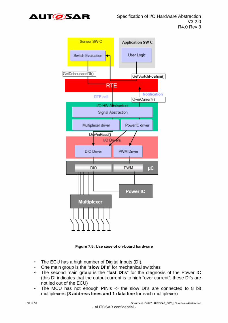
Figure 7.5: Use case of on-board hardware
• The ECU has a high number of Digital Inputs (DI). • One main group is the “slow DI’s” for mechanical switches • The second main group is the “fast DI’s” for the diagnosis of the Power IC
(this DI indicates that the output current is to high “over current”, these DI’s are not led out of the ECU)
• The MCU has not enough PIN’s -> the slow DI’s are connected to 8 bit multiplexers (3 address lines and 1 data line for each multiplexer)
37 of 57 Document ID 047: AUTOSAR_SWS_IOHardwareAbstraction - AUTOSAR confidential -
Specification of I/O Hardware Abstraction V3.2.0
R4.0 Rev 3
• the maximum time between the occurrence of an “over current” and the switch of the Power IC is 1 ms
• One OEM requirement is that the reaction of a switch must be not later than 100 ms
• One other OEM requirement is that each DI must be debounced by 3 of 5 voting. However the practice shows that the kind of debouncing is not really important because the mechanical switches and the power IC do not generate disturbing signals
The solution today is that all DI (slow and fast) are read every 0,8 ms (cyclic task) (The scan rate for the slow DI could be lower but the overhead for an additional task is higher than the runtime savings)
• The debouncing for the slow DI’s is 1 time in every loop (so the worst cast delay to the debounced value is 3,2 ms)
• If an overcurrent is detected the pin will read again several times but in the same loop and the power IC will switched off immediately
• The application runs every 10 ms and reads the debounced DI for the switches and the diagnosis information's
Decomposition on the AUTOSAR architecture: Layer Multiplexed I/O Power IC Application Runnable reads the data every
10 ms gets a notification if the power IC detects overcurrent.
Handles runnables RTE 8 signal mapped on ports, definition of port feature and Client/Server interface
I/O Hardware Abstraction I/O Hardware Abstraction makes decision to switch off the Power IC if an overcurrent is detected (in the driver of the external ASIC)
signal abstraction gives the debounce time (better than a debounce voting rule) a cyclic task performs a
reading of input via DIO service call.
A cyclic task performs a reading of input via DIO service call
MCAL driver DIO driver: adress lines, 1 data line
DIO driver: 1 feedback line from power IC PWM driver: 1 line to the power IC
ECU hardware Multiplexer: Mapping of 8 electrical signal
Power IC: Controls the power supply of the multiplexer
7.12.2 EXAMPLE 2: Use case of failure monitoring
In this example, an diagnostic output signal shall be defined with the diagnosis attribute on the level of the I/O Hardware Abstraction. Therefore, an input is used to perform the diagnosis of the output.
38 of 57 Document ID 047: AUTOSAR_SWS_IOHardwareAbstraction - AUTOSAR confidential -
Specification of I/O Hardware Abstraction V3.2.0
R4.0 Rev 3
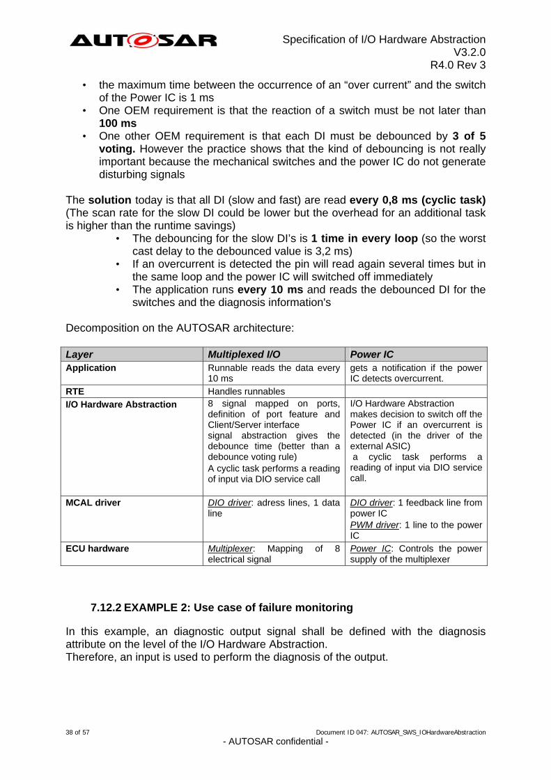
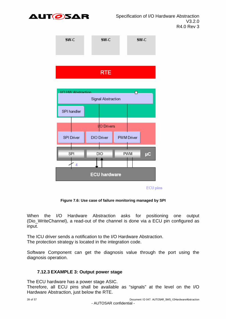
Figure 7.6: Use case of failure monitoring managed by SPI When the I/O Hardware Abstraction asks for positioning one output (Dio_WriteChannel), a read-out of the channel is done via a ECU pin configured as input. The ICU driver sends a notification to the I/O Hardware Abstraction. The protection strategy is located in the integration code. Software Component can get the diagnosis value through the port using the diagnosis operation.
7.12.3 EXAMPLE 3: Output power stage
The ECU hardware has a power stage ASIC. Therefore, all ECU pins shall be available as “signals” at the level on the I/O Hardware Abstraction, just below the RTE.
39 of 57 Document ID 047: AUTOSAR_SWS_IOHardwareAbstraction - AUTOSAR confidential -
Specification of I/O Hardware Abstraction V3.2.0
R4.0 Rev 3
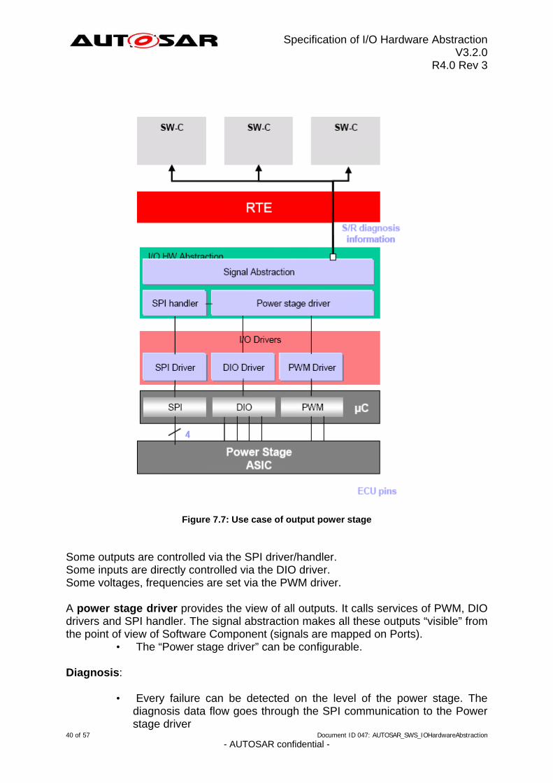
Figure 7.7: Use case of output power stage
Some outputs are controlled via the SPI driver/handler. Some inputs are directly controlled via the DIO driver. Some voltages, frequencies are set via the PWM driver. A power stage driver provides the view of all outputs. It calls services of PWM, DIO drivers and SPI handler. The signal abstraction makes all these outputs “visible” from the point of view of Software Component (signals are mapped on Ports).
• The “Power stage driver” can be configurable.
40 of 57 Document ID 047: AUTOSAR_SWS_IOHardwareAbstraction - AUTOSAR confidential -
Diagnosis:
• Every failure can be detected on the level of the power stage. The diagnosis data flow goes through the SPI communication to the Power stage driver
Specification of I/O Hardware Abstraction V3.2.0
R4.0 Rev 3
• Then, the diagnosis is provided to all Software Component via a S/R interface.
• The diagnosis information can also be sent to the DEM
41 of 57 Document ID 047: AUTOSAR_SWS_IOHardwareAbstraction - AUTOSAR confidential -
Specification of I/O Hardware Abstraction V3.2.0
R4.0 Rev 3
8 API specification
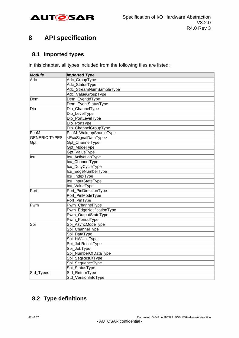
8.1 Imported types
In this chapter, all types included from the following files are listed: Module Imported Type
Adc_GroupType Adc_StatusType
Adc
Adc_StreamNumSampleType Adc_ValueGroupType Dem_EventIdType Dem Dem_EventStatusType Dio_ChannelType Dio_LevelType
Dio
Dio_PortLevelType Dio_PortType Dio_ChannelGroupType
EcuM EcuM_WakeupSourceType GENERIC TYPES <EcuSignalDataType>
Gpt_ChannelType Gpt_ModeType
Gpt
Gpt_ValueType Icu_ActivationType Icu_ChannelType
Icu
Icu_DutyCycleType Icu_EdgeNumberType Icu_IndexType Icu_InputStateType Icu_ValueType Port_PinDirectionType Port_PinModeType
Port
Port_PinType Pwm_ChannelType Pwm_EdgeNotificationType
Pwm
Pwm_OutputStateType Pwm_PeriodType Spi_AsyncModeType Spi_ChannelType
Spi
Spi_DataType Spi_HWUnitType Spi_JobResultType Spi_JobType Spi_NumberOfDataType Spi_SeqResultType Spi_SequenceType Spi_StatusType Std_ReturnType Std_Types Std_VersionInfoType
8.2 Type definitions
42 of 57 Document ID 047: AUTOSAR_SWS_IOHardwareAbstraction - AUTOSAR confidential -
Specification of I/O Hardware Abstraction V3.2.0
R4.0 Rev 3
None
8.3 Function definitions
This is a list of functions provided for upper layer modules. NOTE FOR I/O HARDWARE ABSTRACTION: As explained in the previous chapters, no functional API will be specified for the I/O Hardware Abstraction.
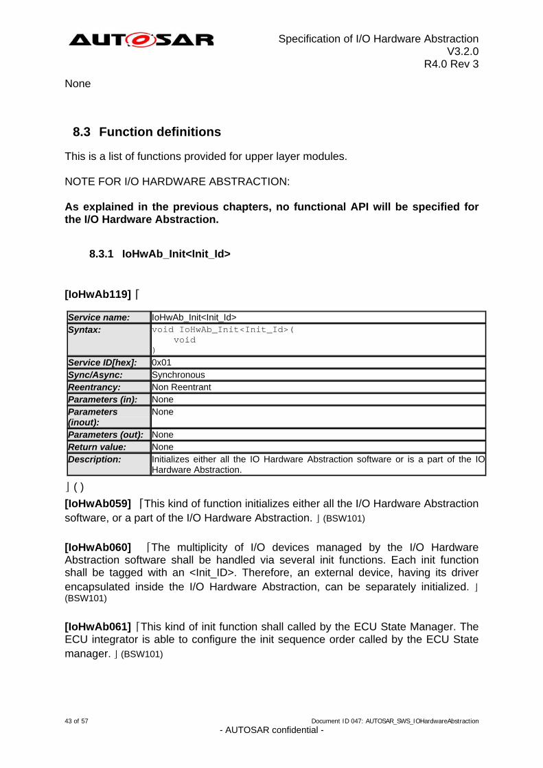
8.3.1 IoHwAb_Init<Init_Id>
[IoHwAb119] ⌈
IoHwAb_Init<Init_Id> Service name: void IoHwAb_Init<Init_Id>( void )
Syntax:
0x01 Service ID[hex]: Synchronous Sync/Async: Non Reentrant Reentrancy: None Parameters (in): None Parameters
(inout): None Parameters (out): None Return value: Initializes either all the IO Hardware Abstraction software or is a part of the IO Hardware Abstraction.
Description:
⌋ ( ) [IoHwAb059] ⌈This kind of function initializes either all the I/O Hardware Abstraction software, or a part of the I/O Hardware Abstraction. ⌋ (BSW101)
[IoHwAb060] ⌈The multiplicity of I/O devices managed by the I/O Hardware Abstraction software shall be handled via several init functions. Each init function shall be tagged with an <Init_ID>. Therefore, an external device, having its driver encapsulated inside the I/O Hardware Abstraction, can be separately initialized. ⌋ (BSW101)
[IoHwAb061] ⌈This kind of init function shall called by the ECU State Manager. The ECU integrator is able to configure the init sequence order called by the ECU State manager. ⌋ (BSW101)
43 of 57 Document ID 047: AUTOSAR_SWS_IOHardwareAbstraction - AUTOSAR confidential -
Specification of I/O Hardware Abstraction V3.2.0
R4.0 Rev 3
[IoHwAb102] ⌈After having finished the module initialization, the I/O Hardware Abstraction state shall be set to IOHWAB_IDLE, the job result shall be set to
IOHWAB_JOB_OK. ⌋ (BSW00441)
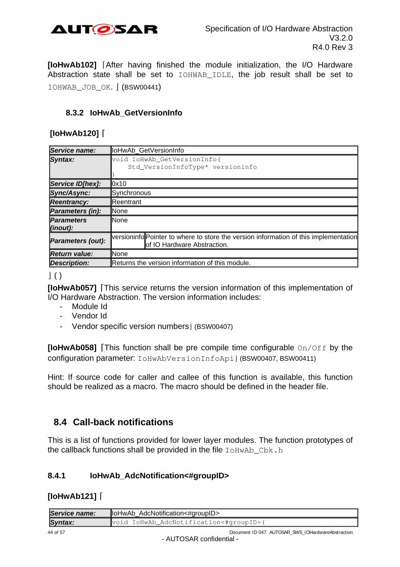
8.3.2 IoHwAb_GetVersionInfo
[IoHwAb120] ⌈ Service name: IoHwAb_GetVersionInfo Syntax: void IoHwAb_GetVersionInfo(
Std_VersionInfoType* versioninfo )
Service ID[hex]: 0x10 Sync/Async: Synchronous Reentrancy: Reentrant Parameters (in): None Parameters (inout):
None
Parameters (out): versioninfo Pointer to where to store the version information of this implementation
of IO Hardware Abstraction. None Return value: Returns the version information of this module. Description:
⌋ ( ) [IoHwAb057] ⌈This service returns the version information of this implementation of I/O Hardware Abstraction. The version information includes:
- Module Id - Vendor Id - Vendor specific version numbers⌋ (BSW00407)
[IoHwAb058] ⌈This function shall be pre compile time configurable On/Off by the configuration parameter: IoHwAbVersionInfoApi⌋ (BSW00407, BSW00411) Hint: If source code for caller and callee of this function is available, this function should be realized as a macro. The macro should be defined in the header file.
8.4 Call-back notifications
This is a list of functions provided for lower layer modules. The function prototypes of the callback functions shall be provided in the file IoHwAb_Cbk.h
8.4.1 IoHwAb_AdcNotification<#groupID>
[IoHwAb121] ⌈
IoHwAb_AdcNotification<#groupID> Service name: Syntax: void IoHwAb_AdcNotification<#groupID>(
44 of 57 Document ID 047: AUTOSAR_SWS_IOHardwareAbstraction - AUTOSAR confidential -
Specification of I/O Hardware Abstraction V3.2.0
R4.0 Rev 3
void ) 0x20 Service ID[hex]: Synchronous Sync/Async: Non Reentrant Reentrancy:
Parameters (in): None Parameters (inout):
None
None Parameters (out): None Return value: Will be called by the ADC Driver when a group conversion is completed for group <#groupID>.
Description:
⌋ ( ) [IoHwAb104] ⌈The function IoHwAb_AdcNotification<#groupID> is intended to be called by the ADC driver when a group conversion is completed for group <#groupID>.⌋ ( )
8.4.2 IoHwAb_PwmNotification<#channel>
[IoHwAb122] ⌈
IoHwAb_PwmNotification<#channel> Service name: void IoHwAb_PwmNotification<#channel>( void )
Syntax:
Service ID[hex]: 0x30 Sync/Async: Synchronous Reentrancy: Non Reentrant Parameters (in): None Parameters (inout):
None
Parameters (out): None Return value: None Description: Will be called by the PWM Driver when a signal edge occurs on channel
<#channel>.
⌋ ( ) [IoHwAb105] ⌈The function IoHwAb_PwmNotification<#channel> is intended to be
called by the PWM driver when a signal edge occurs on channel <#channel>.⌋ ( )
8.4.3 IoHwAb_IcuNotification<#channel>
[IoHwAb123] ⌈
IoHwAb_IcuNotification<#channel> Service name: void IoHwAb_IcuNotification<#channel>( void )
Syntax:
Service ID[hex]: 0x40
45 of 57 Document ID 047: AUTOSAR_SWS_IOHardwareAbstraction - AUTOSAR confidential -
Specification of I/O Hardware Abstraction V3.2.0
R4.0 Rev 3
Sync/Async: Synchronous Reentrancy: Non Reentrant Parameters (in): None Parameters (inout):
None
Parameters (out): None Return value: None Description: Will be called by the ICU driver when a signal edge occurs on channel
<#channel>.
⌋ ( ) [IoHwAb106] ⌈The function IoHwAb_IcuNotification<#channel> is intended to be called by the ICU driver when a signal edge occurs on channel <#channel>.⌋ ( )
8.4.4 IoHwAb_GptNotification<#channel>
[IoHwAb124] ⌈
IoHwAb_GptNotification<#channel> Service name: void IoHwAb_GptNotification<#channel>( void )
Syntax:
Service ID[hex]: 0x50 Sync/Async: Synchronous Reentrancy: Non Reentrant Parameters (in): None Parameters (inout):
None
Parameters (out): None Return value: None Description: Will be called by the GPT driver when a timer value expires on channel
<#channel>.
⌋ ( ) [IoHwAb107] ⌈The function IoHwAb_GptNotification<#channel> is intended to be called by the GPT driver when a timer value expires on channel <#channel>.⌋ ( )
8.5 Scheduled functions
These functions are directly called by Basic Software Scheduler. The following functions shall have no return value and no parameter. All functions shall be non-reentrant.
8.5.1 <Name of scheduled function>
<Name of API call> Service name: <Number of service ID. This ID is used as parameter for the error report API of Development Error Tracer. The ID shall not be equal to an ID within chapter 8.3>
Service ID [hex]:
Description: <Set of local software requirements including ID that define the operation of this API call.>
46 of 57 Document ID 047: AUTOSAR_SWS_IOHardwareAbstraction - AUTOSAR confidential -
Specification of I/O Hardware Abstraction V3.2.0
R4.0 Rev 3
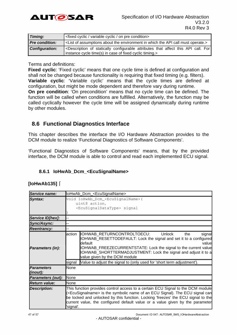
Timing: <fixed cyclic / variable cyclic / on pre condition>
Pre condition: <List of assumptions about the environment in which the API call must operate.>
Configuration: <Description of statically configurable attributes that affect this API call. For instance cycle time(s) in case of fixed cyclic timing.>
Terms and definitions: Fixed cyclic: ‘Fixed cyclic’ means that one cycle time is defined at configuration and shall not be changed because functionality is requiring that fixed timing (e.g. filters). Variable cyclic: ‘Variable cyclic’ means that the cycle times are defined at configuration, but might be mode dependent and therefore vary during runtime. On pre condition: ‘On precondition’ means that no cycle time can be defined. The function will be called when conditions are fulfilled. Alternatively, the function may be called cyclically however the cycle time will be assigned dynamically during runtime by other modules.
8.6 Functional Diagnostics Interface
This chapter describes the interface the I/O Hardware Abstraction provides to the DCM module to realize ‘Functional Diagnostics of Software Components’. ‘Functional Diagnostics of Software Components’ means, that by the provided interface, the DCM module is able to control and read each implemented ECU signal.
8.6.1 IoHwAb_Dcm_<EcuSignalName>
[IoHwAb135] ⌈ Service name: IoHwAb_Dcm_<EcuSignalName> Syntax: void IoHwAb_Dcm_<EcuSignalName>(
uint8 action, <EcuSignalDataType> signal ) -- Service ID[hex]: -- Sync/Async: -- Reentrancy: action IOHWAB_RETURNCONTROLTOECU: Unlock the signal
IOHWAB_RESETTODEFAULT: Lock the signal and set it to a configured default valueIOHWAB_FREEZECURRENTSTATE: Lock the signal to the current valueIOHWAB_SHORTTERMADJUSTMENT: Lock the signal and adjust it to a value given by the DCM module
Parameters (in):
signal Value to adjust the signal to (only used for 'short term adjustment'). Parameters (inout):
None
Parameters (out): None None Return value:
Description: This function provides control access to a certain ECU Signal to the DCM module (<EcuSignalname> is the symbolic name of an ECU Signal). The ECU signal can be locked and unlocked by this function. Locking 'freezes' the ECU signal to the current value, the configured default value or a value given by the parameter 'signal'.
47 of 57 Document ID 047: AUTOSAR_SWS_IOHardwareAbstraction - AUTOSAR confidential -
Specification of I/O Hardware Abstraction V3.2.0
R4.0 Rev 3
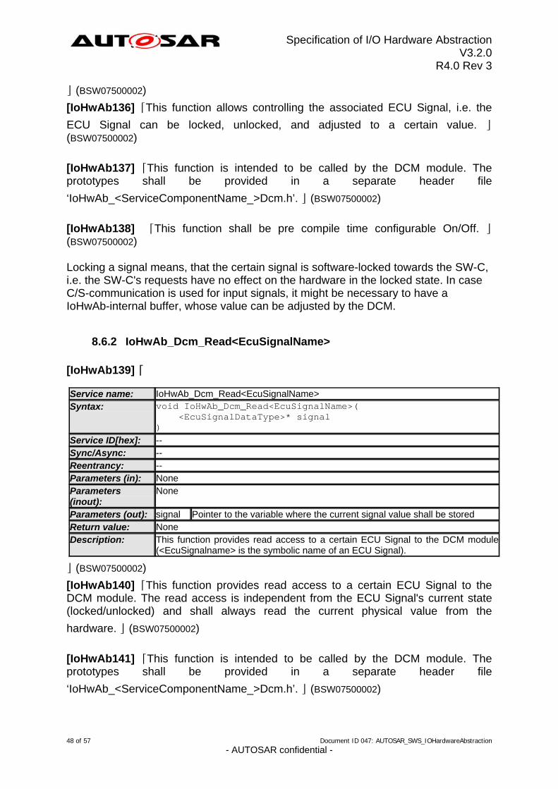
⌋ (BSW07500002)
[IoHwAb136] ⌈This function allows controlling the associated ECU Signal, i.e. the
ECU Signal can be locked, unlocked, and adjusted to a certain value. ⌋ (BSW07500002)
[IoHwAb137] ⌈This function is intended to be called by the DCM module. The prototypes shall be provided in a separate header file
‘IoHwAb_<ServiceComponentName_>Dcm.h’. ⌋ (BSW07500002)
[IoHwAb138] ⌈This function shall be pre compile time configurable On/Off. ⌋ (BSW07500002) Locking a signal means, that the certain signal is software-locked towards the SW-C, i.e. the SW-C's requests have no effect on the hardware in the locked state. In case C/S-communication is used for input signals, it might be necessary to have a IoHwAb-internal buffer, whose value can be adjusted by the DCM.
8.6.2 IoHwAb_Dcm_Read<EcuSignalName>
[IoHwAb139] ⌈
IoHwAb_Dcm_Read<EcuSignalName> Service name: void IoHwAb_Dcm_Read<EcuSignalName>( <EcuSignalDataType>* signal )
Syntax:
-- Service ID[hex]: Sync/Async: -- Reentrancy: -- Parameters (in): None Parameters (inout):
None
Parameters (out): signal Pointer to the variable where the current signal value shall be stored None Return value: This function provides read access to a certain ECU Signal to the DCM module (<EcuSignalname> is the symbolic name of an ECU Signal).
Description:
⌋ (BSW07500002)
[IoHwAb140] ⌈This function provides read access to a certain ECU Signal to the DCM module. The read access is independent from the ECU Signal's current state (locked/unlocked) and shall always read the current physical value from the
hardware. ⌋ (BSW07500002)
[IoHwAb141] ⌈This function is intended to be called by the DCM module. The prototypes shall be provided in a separate header file
‘IoHwAb_<ServiceComponentName_>Dcm.h’. ⌋ (BSW07500002)
48 of 57 Document ID 047: AUTOSAR_SWS_IOHardwareAbstraction - AUTOSAR confidential -
Specification of I/O Hardware Abstraction V3.2.0
R4.0 Rev 3
[IoHwAb142] ⌈This function shall be pre compile time configurable On/Off. ⌋ (BSW07500002)
8.7 Expected Interfaces
In this chapter, all interfaces required from other modules are listed.
8.7.1 Mandatory Interfaces
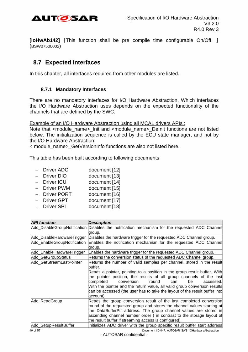
There are no mandatory interfaces for I/O Hardware Abstraction. Which interfaces the I/O Hardware Abstraction uses depends on the expected functionality of the channels that are defined by the SWC. Example of an I/O Hardware Abstraction using all MCAL drivers APIs : Note that <module_name>_Init and <module_name>_DeInit functions are not listed below. The initialization sequence is called by the ECU state manager, and not by the I/O Hardware Abstraction. < module_name>_GetVersionInfo functions are also not listed here. This table has been built according to following documents
Driver ADC document [12] Driver DIO document [13] Driver ICU document [14] Driver PWM document [15] Driver PORT document [16] Driver GPT document [17] Driver SPI document [18]
API function Description Adc_DisableGroupNotification Disables the notification mechanism for the requested ADC Channel
group. Adc_DisableHardwareTrigger Disables the hardware trigger for the requested ADC Channel group. Adc_EnableGroupNotification Enables the notification mechanism for the requested ADC Channel
group. Adc_EnableHardwareTrigger Enables the hardware trigger for the requested ADC Channel group. Adc_GetGroupStatus Returns the conversion status of the requested ADC Channel group. Adc_GetStreamLastPointer Returns the number of valid samples per channel, stored in the result
buffer. Reads a pointer, pointing to a position in the group result buffer. With the pointer position, the results of all group channels of the last completed conversion round can be accessed. With the pointer and the return value, all valid group conversion results can be accessed (the user has to take the layout of the result buffer into account).
Adc_ReadGroup Reads the group conversion result of the last completed conversion round of the requested group and stores the channel values starting at the DataBufferPtr address. The group channel values are stored in ascending channel number order ( in contrast to the storage layout of the result buffer if streaming access is configured).
Adc_SetupResultBuffer Initializes ADC driver with the group specific result buffer start address 49 of 57 Document ID 047: AUTOSAR_SWS_IOHardwareAbstraction
- AUTOSAR confidential -
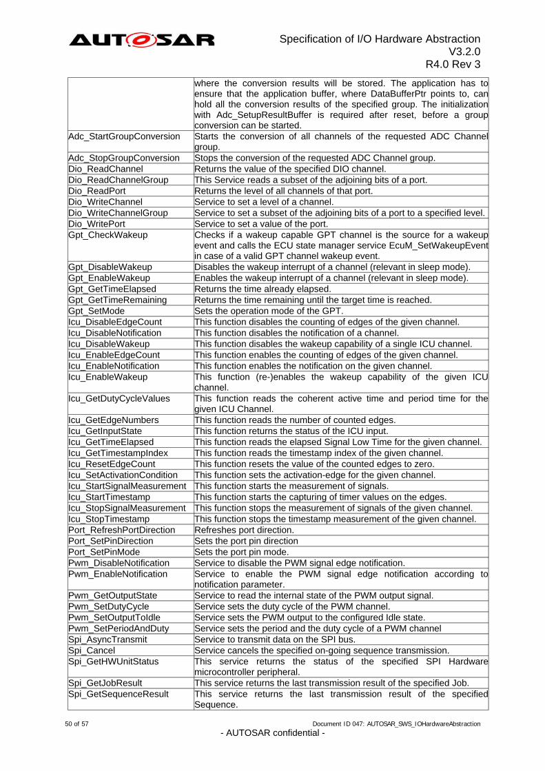
Specification of I/O Hardware Abstraction V3.2.0
R4.0 Rev 3
where the conversion results will be stored. The application has to ensure that the application buffer, where DataBufferPtr points to, can hold all the conversion results of the specified group. The initialization with Adc_SetupResultBuffer is required after reset, before a group conversion can be started.
Adc_StartGroupConversion Starts the conversion of all channels of the requested ADC Channel group.
Adc_StopGroupConversion Stops the conversion of the requested ADC Channel group. Dio_ReadChannel Returns the value of the specified DIO channel. Dio_ReadChannelGroup This Service reads a subset of the adjoining bits of a port. Dio_ReadPort Returns the level of all channels of that port. Dio_WriteChannel Service to set a level of a channel. Dio_WriteChannelGroup Service to set a subset of the adjoining bits of a port to a specified level.Dio_WritePort Service to set a value of the port. Gpt_CheckWakeup Checks if a wakeup capable GPT channel is the source for a wakeup
event and calls the ECU state manager service EcuM_SetWakeupEvent in case of a valid GPT channel wakeup event.
Gpt_DisableWakeup Disables the wakeup interrupt of a channel (relevant in sleep mode). Gpt_EnableWakeup Enables the wakeup interrupt of a channel (relevant in sleep mode). Gpt_GetTimeElapsed Returns the time already elapsed. Gpt_GetTimeRemaining Returns the time remaining until the target time is reached. Gpt_SetMode Sets the operation mode of the GPT. Icu_DisableEdgeCount This function disables the counting of edges of the given channel. Icu_DisableNotification This function disables the notification of a channel. Icu_DisableWakeup This function disables the wakeup capability of a single ICU channel. Icu_EnableEdgeCount This function enables the counting of edges of the given channel. Icu_EnableNotification This function enables the notification on the given channel. Icu_EnableWakeup This function (re-)enables the wakeup capability of the given ICU
channel. Icu_GetDutyCycleValues This function reads the coherent active time and period time for the
given ICU Channel. Icu_GetEdgeNumbers This function reads the number of counted edges. Icu_GetInputState This function returns the status of the ICU input. Icu_GetTimeElapsed This function reads the elapsed Signal Low Time for the given channel. Icu_GetTimestampIndex This function reads the timestamp index of the given channel. Icu_ResetEdgeCount This function resets the value of the counted edges to zero. Icu_SetActivationCondition This function sets the activation-edge for the given channel. Icu_StartSignalMeasurement This function starts the measurement of signals. Icu_StartTimestamp This function starts the capturing of timer values on the edges. Icu_StopSignalMeasurement This function stops the measurement of signals of the given channel. Icu_StopTimestamp This function stops the timestamp measurement of the given channel. Port_RefreshPortDirection Refreshes port direction. Port_SetPinDirection Sets the port pin direction Port_SetPinMode Sets the port pin mode. Pwm_DisableNotification Service to disable the PWM signal edge notification. Pwm_EnableNotification Service to enable the PWM signal edge notification according to
notification parameter. Pwm_GetOutputState Service to read the internal state of the PWM output signal. Pwm_SetDutyCycle Service sets the duty cycle of the PWM channel. Pwm_SetOutputToIdle Service sets the PWM output to the configured Idle state. Pwm_SetPeriodAndDuty Service sets the period and the duty cycle of a PWM channel Spi_AsyncTransmit Service to transmit data on the SPI bus. Spi_Cancel Service cancels the specified on-going sequence transmission. Spi_GetHWUnitStatus This service returns the status of the specified SPI Hardware
microcontroller peripheral. Spi_GetJobResult This service returns the last transmission result of the specified Job. Spi_GetSequenceResult This service returns the last transmission result of the specified
Sequence.
50 of 57 Document ID 047: AUTOSAR_SWS_IOHardwareAbstraction - AUTOSAR confidential -
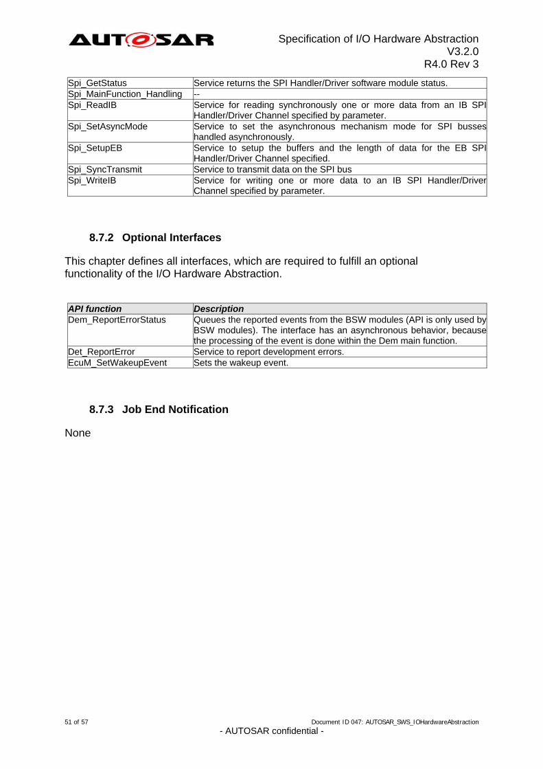
Specification of I/O Hardware Abstraction V3.2.0
R4.0 Rev 3
Spi_GetStatus Service returns the SPI Handler/Driver software module status. Spi_MainFunction_Handling -- Spi_ReadIB Service for reading synchronously one or more data from an IB SPI
Handler/Driver Channel specified by parameter. Spi_SetAsyncMode Service to set the asynchronous mechanism mode for SPI busses
handled asynchronously. Spi_SetupEB Service to setup the buffers and the length of data for the EB SPI
Handler/Driver Channel specified. Spi_SyncTransmit Service to transmit data on the SPI bus Spi_WriteIB Service for writing one or more data to an IB SPI Handler/Driver
Channel specified by parameter.
8.7.2 Optional Interfaces
This chapter defines all interfaces, which are required to fulfill an optional functionality of the I/O Hardware Abstraction. API function Description Dem_ReportErrorStatus Queues the reported events from the BSW modules (API is only used by
BSW modules). The interface has an asynchronous behavior, because the processing of the event is done within the Dem main function.
Det_ReportError Service to report development errors. EcuM_SetWakeupEvent Sets the wakeup event.
8.7.3 Job End Notification
None
51 of 57 Document ID 047: AUTOSAR_SWS_IOHardwareAbstraction - AUTOSAR confidential -
Specification of I/O Hardware Abstraction V3.2.0
R4.0 Rev 3
9 Sequence diagrams
9.1 ECU-signal provided by the I/O Hardware Abstraction (example)
This sequence diagram explains the example of chapter 7.5.2.5. In this example, the Sensor / Actuator Component is the client, the I/O Hardware Abstraction is the server. The Sensor/Actuator Component asks for a new value of the af_pressure AUTOSAR signal that is an ECU signal on the level of the I/O Hardware Abstraction. After Adc conversion is finished, a notification coming from MCAL driver is converted into a RTE event for the Sensor / Actuator Component. Then, it can perform a synchronous read of the value present in the af_pressure signal buffer.
52 of 57 Document ID 047: AUTOSAR_SWS_IOHardwareAbstraction - AUTOSAR confidential -
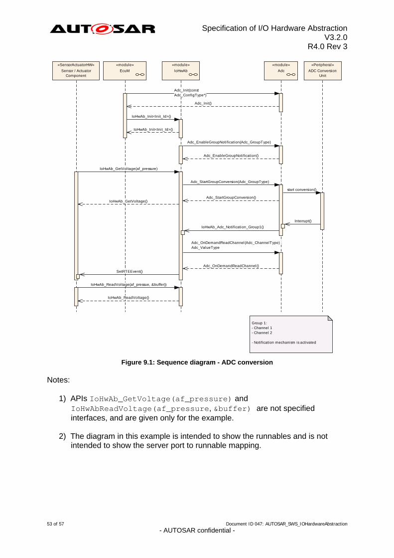
Specification of I/O Hardware Abstraction V3.2.0
R4.0 Rev 3
«module»
Adc
«Peripheral»
ADC ConversionUnit
«module»
IoHwAb
«module»
EcuM
«SensorActuatorHW»
Sensor / ActuatorComponent
Adc_Init(constAdc_ConfigType*)
Adc_Init()
IoHwAb_Init<Init_Id>()
IoHwAb_Init<Init_Id>()
Adc_EnableGroupNotification(Adc_GroupType)
Adc_EnableGroupNotification()
IoHwAb_GetVoltage(af_pressure)
Adc_StartGroupConversion(Adc_GroupType)
start conversion()
Adc_StartGroupConversion()IoHwAb_GetVoltage()
Interrupt()
IoHwAb_Adc_Notification_Group1()
Adc_OnDemandReadChannel(Adc_ChannelType) :Adc_ValueType
Adc_OnDemandReadChannel()
SetRTEEvent()
IoHwAb_ReadVoltage(af_pressue, &buffer))
IoHwAb_ReadVoltage()
Group 1:- Channel 1- Channel 2
- Notification mechanism is activated
Figure 9.1: Sequence diagram - ADC conversion
Notes:
1) APIs IoHwAb_GetVoltage(af_pressure) and IoHwAbReadVoltage(af_pressure, &buffer) are not specified interfaces, and are given only for the example.
2) The diagram in this example is intended to show the runnables and is not intended to show the server port to runnable mapping.
53 of 57 Document ID 047: AUTOSAR_SWS_IOHardwareAbstraction - AUTOSAR confidential -
Specification of I/O Hardware Abstraction V3.2.0
R4.0 Rev 3
10 Configuration specification
The I/O Hardware Abstraction has no standardized configuration parameters and is therefore not part of the AUTOSAR ECU-C Parameter Definition. All parameters are vendor specific parameters.
10.1 Published Information
[IoHwAb144] ⌈The standardized common published parameters as required by BSW00402 in the General Requirements on Basic Software Modules [3] shall be published within the header file of this module and need to be provided in the BSW Module Description. The according module abbreviation can be found in the List of
Basic Software Modules [1]. ⌋ ( ) Additional module-specific published parameters are listed below if applicable.
54 of 57 Document ID 047: AUTOSAR_SWS_IOHardwareAbstraction - AUTOSAR confidential -
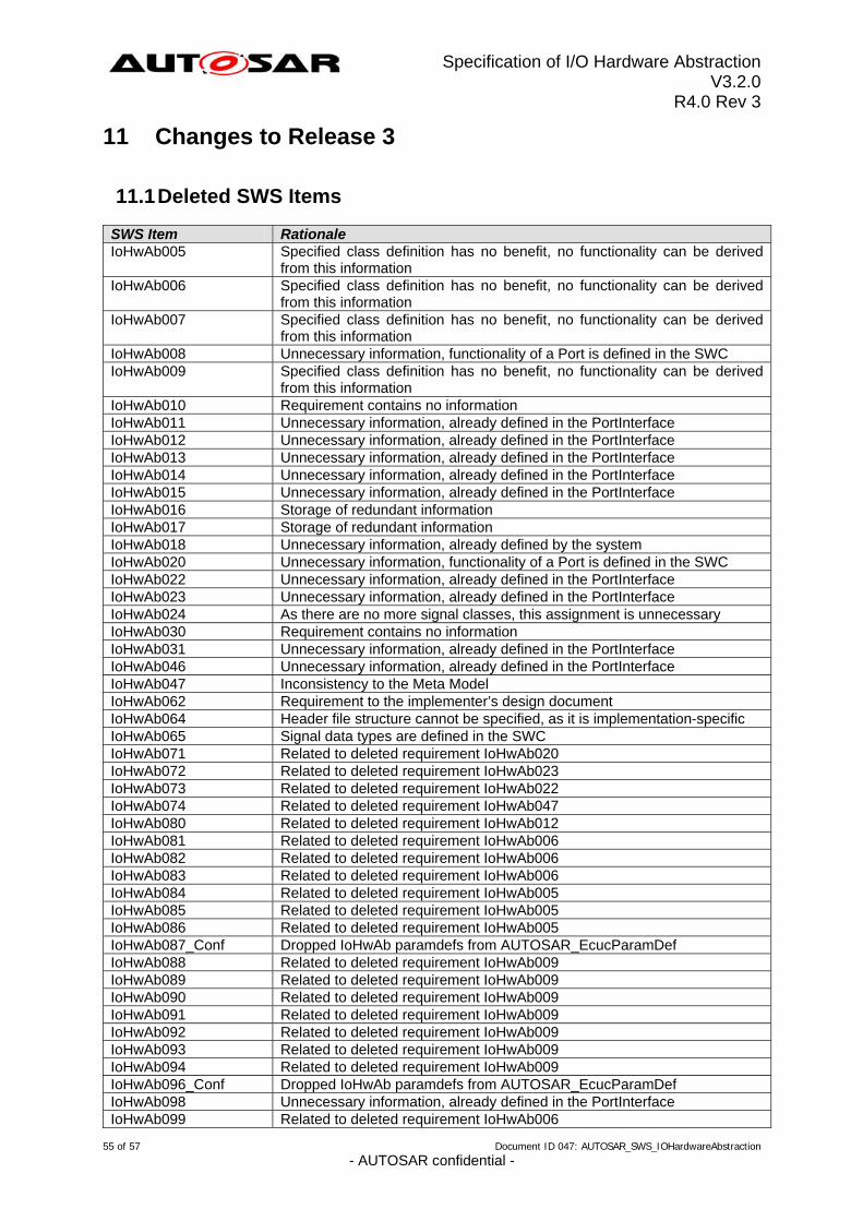
Specification of I/O Hardware Abstraction V3.2.0
R4.0 Rev 3
11 Changes to Release 3
11.1 Deleted SWS Items
SWS Item Rationale IoHwAb005 Specified class definition has no benefit, no functionality can be derived
from this information IoHwAb006 Specified class definition has no benefit, no functionality can be derived
from this information IoHwAb007 Specified class definition has no benefit, no functionality can be derived
from this information IoHwAb008 Unnecessary information, functionality of a Port is defined in the SWC IoHwAb009 Specified class definition has no benefit, no functionality can be derived
from this information IoHwAb010 Requirement contains no information IoHwAb011 Unnecessary information, already defined in the PortInterface IoHwAb012 Unnecessary information, already defined in the PortInterface IoHwAb013 Unnecessary information, already defined in the PortInterface IoHwAb014 Unnecessary information, already defined in the PortInterface IoHwAb015 Unnecessary information, already defined in the PortInterface IoHwAb016 Storage of redundant information IoHwAb017 Storage of redundant information IoHwAb018 Unnecessary information, already defined by the system IoHwAb020 Unnecessary information, functionality of a Port is defined in the SWC IoHwAb022 Unnecessary information, already defined in the PortInterface IoHwAb023 Unnecessary information, already defined in the PortInterface IoHwAb024 As there are no more signal classes, this assignment is unnecessary IoHwAb030 Requirement contains no information IoHwAb031 Unnecessary information, already defined in the PortInterface IoHwAb046 Unnecessary information, already defined in the PortInterface IoHwAb047 Inconsistency to the Meta Model IoHwAb062 Requirement to the implementer’s design document IoHwAb064 Header file structure cannot be specified, as it is implementation-specific IoHwAb065 Signal data types are defined in the SWC IoHwAb071 Related to deleted requirement IoHwAb020 IoHwAb072 Related to deleted requirement IoHwAb023 IoHwAb073 Related to deleted requirement IoHwAb022 IoHwAb074 Related to deleted requirement IoHwAb047 IoHwAb080 Related to deleted requirement IoHwAb012 IoHwAb081 Related to deleted requirement IoHwAb006 IoHwAb082 Related to deleted requirement IoHwAb006 IoHwAb083 Related to deleted requirement IoHwAb006 IoHwAb084 Related to deleted requirement IoHwAb005 IoHwAb085 Related to deleted requirement IoHwAb005 IoHwAb086 Related to deleted requirement IoHwAb005 IoHwAb087_Conf Dropped IoHwAb paramdefs from AUTOSAR_EcucParamDef IoHwAb088 Related to deleted requirement IoHwAb009 IoHwAb089 Related to deleted requirement IoHwAb009 IoHwAb090 Related to deleted requirement IoHwAb009 IoHwAb091 Related to deleted requirement IoHwAb009 IoHwAb092 Related to deleted requirement IoHwAb009 IoHwAb093 Related to deleted requirement IoHwAb009 IoHwAb094 Related to deleted requirement IoHwAb009 IoHwAb096_Conf Dropped IoHwAb paramdefs from AUTOSAR_EcucParamDef IoHwAb098 Unnecessary information, already defined in the PortInterface IoHwAb099 Related to deleted requirement IoHwAb006
55 of 57 Document ID 047: AUTOSAR_SWS_IOHardwareAbstraction - AUTOSAR confidential -
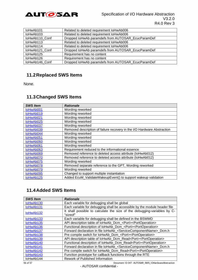
Specification of I/O Hardware Abstraction V3.2.0
R4.0 Rev 3
IoHwAb101 Related to deleted requirement IoHwAb006 IoHwAb103 Related to deleted requirement IoHwAb006 IoHwAb110_Conf Dropped IoHwAb paramdefs from AUTOSAR_EcucParamDef IoHwAb113 Related to deleted requirement IoHwAb006 IoHwAb114 Related to deleted requirement IoHwAb006 IoHwAb121_Conf Dropped IoHwAb paramdefs from AUTOSAR_EcucParamDef IoHwAb125 Requirement has no content IoHwAb126 Requirement has no content IoHwAb146_Conf Dropped IoHwAb paramdefs from AUTOSAR_EcucParamDef
11.2 Replaced SWS Items
None.
11.3 Changed SWS Items
SWS Item Rationale IoHwAb001 Wording reworked IoHwAb019 Wording reworked IoHwAb021 Wording reworked IoHwAb025 Wording reworked IoHwAb037 Wording reworked IoHwAb039 Removed description of failure recovery in the I/O Hardware Abstraction IoHwAb044 Wording reworked IoHwAb051 Wording reworked IoHwAb060 Wording reworked IoHwAb061 Wording reworked IoHwAb063 Requirement reduced to the informational essence IoHwAb069 Removed reference to deleted access attribute (IoHwAb012) IoHwAb070 Removed reference to deleted access attribute (IoHwAb012) IoHwAb075 Wording reworked IoHwAb078 Removed separate reference to the GPT, Wording reworked IoHwAb079 Wording reworked IoHwAb095 Changed to support multiple instantiation IoHwAb125 Added EcuM_ValidateWakeupEvent() to support wakeup validation
11.4 Added SWS Items
SWS Item Rationale IoHwAb130 Each variable for debugging shall be global IoHwAb131 Each variable for debugging shall be accessible by the module header file
It shall possible to calculate the size of the debugging-variables by C-"sizeof"
IoHwAb132
IoHwAb133 Each variable for debugging shall be defined in the BSWMD IoHwAb135 API description table of IoHwAb_Dcm_<Port><PortOperation> IoHwAb136 Functional description of IoHwAb_Dcm_<Port><PortOperation> IoHwAb137 Forward declaration in file IoHwAb_<ServiceComponentName>_Dcm.h IoHwAb138 Pre compile switch for IoHwAb_Dcm_<Port><PortOperation> IoHwAb139 API description table of IoHwAb_Dcm_Read<Port><PortOperation> IoHwAb140 Functional description of IoHwAb_Dcm_Read<Port><PortOperation> IoHwAb141 Forward declaration in file IoHwAb_<ServiceComponentName>_Dcm.h IoHwAb142 Pre compile switch for IoHwAb_Dcm_Read<Port><PortOperation> IoHwAb143 Function prototype for callback functions through the RTE IoHwAb144 Rework of Published Information
56 of 57 Document ID 047: AUTOSAR_SWS_IOHardwareAbstraction - AUTOSAR confidential -
Specification of I/O Hardware Abstraction V3.2.0
R4.0 Rev 3
57 of 57 Document ID 047: AUTOSAR_SWS_IOHardwareAbstraction - AUTOSAR confidential -
12 Not applicable requirements
[IoHwAb145] ⌈These requirements are not applicable to this specification.⌋ (BSW00300, BSW00321, BSW00325, BSW00326, BSW00329, BSW00334, BSW00341, BSW00342, BSW00343, BSW00376, BSW00398, BSW00399, BSW00400, BSW00404, BSW00405, BSW00416, BSW00417, BSW00424, BSW00428, BSW00432, BSW00439, BSW005, BSW007, BSW160, BSW161, BSW162, BSW164, BSW167, BSW168, BSW170, BSW12057, BSW12063, BSW12064, BSW12067, BSW12068, BSW12069, BSW12075, BSW12077, BSW12078, BSW12092, BSW12125, BSW12129, BSW12163, BSW12169, BSW12263, BSW12264, BSW12265, BSW12267, BSW12461, BSW12462, BSW12463, BSW157)