Specification for Wire Rope - PSLCOLOMBIA SPEC 9A... · API standard or, where an extension has...
68
Specification for Wire Rope ANSI/API Specification 9A Twenty-fifth Edition, February 2004 ISO 10425:2003, Steel wire ropes for the petroleum and natural gas industries—Minimum requirements and terms for acceptance EFFECTIVE DATE: AUGUST 2004 ANSI/API 9A/ISO 10425-2003 Copyright American Petroleum Institute Reproduced by IHS under license with API Questions or comments about this message: please call the Document Policy Group at 303-397-2295. --`,,`,,```,`,`,,`,,`,``,,`,,``-`-`,,`,,`,`,,`---
Transcript of Specification for Wire Rope - PSLCOLOMBIA SPEC 9A... · API standard or, where an extension has...

Specification for Wire Rope ANSI/API Specification 9A Twenty-fifth Edition, February 2004 ISO 10425:2003, Steel wire ropes for the petroleum and natural gas industries—Minimum requirements and terms for acceptance EFFECTIVE DATE: AUGUST 2004 ANSI/API 9A/ISO 10425-2003
Copyright American Petroleum Institute Reproduced by IHS under license with API
--`,,`,,```,`,`,,`,,`,``,,`,,``-`-`,,`,,`,`,,`---
Document provided by IHS Licensee=HOCOL S A/9984411001, 03/29/2005 09:56:34 MSTQuestions or comments about this message: please call the Document Policy Groupat 303-397-2295.

Copyright American Petroleum Institute Reproduced by IHS under license with API
Document provided by IHS Licensee=HOCOL S A/9984411001, 03/29/2005 09:56:34 MSTQuestions or comments about this message: please call the Document Policy Groupat 303-397-2295.
--`,,`,,```,`,`,,`,,`,``,,`,,``-`-`,,`,,`,`,,`---

Special Notes
API publications necessarily address problems of a general nature. With respect to particular circumstances, local, state, and federal laws and regulations should be reviewed.
API is not undertaking to meet the duties of employers, manufacturers, or suppliers to warn and properly train and equip their employees, and others exposed, concerning health and safety risks and precautions, nor undertaking their obligations under local, state, or federal laws.
Information concerning safety and health risks and proper precautions with respect to particular materials and conditions should be obtained from the employer, the manufacturer or supplier of that material, or the material safety data sheet.
Nothing contained in any API publication is to be construed as granting any right, by implication or otherwise, for the manufacture, sale, or use of any method, apparatus, or product covered by letters patent. Neither should anything contained in the publication be construed as insuring anyone against liability for infringement of letters patent.
Generally, API standards are reviewed and revised, reaffirmed, or withdrawn at least every five years. Sometimes a one-time extension of up to two years will be added to this review cycle. This publication will no longer be in effect five years after its publication date as an operative API standard or, where an extension has been granted, upon republication. Status of the publication can be ascertained from the API Standards department telephone (202) 682-8000. A catalog of API publications, programs and services is published annually and updated biannually by API, and available through Global Engineering Documents, 15 Inverness Way East, M/S C303B, Englewood, CO 80112-5776.
This document was produced under API standardization procedures that ensure appropriate notification and participation in the developmental process and is designated as an API standard. Questions concerning the interpretation of the content of this standard or comments and questions concerning the procedures under which this standard was developed should be directed in writing to the Director of the Standards department, American Petroleum Institute, 1220 L Street, N.W., Washington, D.C. 20005. Requests for permission to reproduce or translate all or any part of the material published herein should be addressed to the Director, Business Services.
API standards are published to facilitate the broad availability of proven, sound engineering and operating practices. These standards are not intended to obviate the need for applying sound engineering judgment regarding when and where these standards should be utilized. The formulation and publication of API standards is not intended in any way to inhibit anyone from using any other practices.
Any manufacturer marking equipment or materials in conformance with the marking requirements of an API standard is solely responsible for complying with all the applicable requirements of that standard. API does not represent, warrant, or guarantee that such products do in fact conform to the applicable API standard.
All rights reserved. No part of this work may be reproduced, stored in a retrieval system, or transmitted by any means, electronic, mechanical, photocopying, recording, or
otherwise, without prior written permission from the publisher. Contact the Publisher, API Publishing Services, 1220 L Street, N.W., Washington, D.C. 20005.
Copyright © 2004 American Petroleum Institute
Copyright American Petroleum Institute Reproduced by IHS under license with API
Document provided by IHS Licensee=HOCOL S A/9984411001, 03/29/2005 09:56:34 MSTQuestions or comments about this message: please call the Document Policy Groupat 303-397-2295.
--`,,`,,```,`,`,,`,,`,``,,`,,``-`-`,,`,,`,`,,`---

API Foreword
This standard shall become effective on the date printed on the cover but may be used voluntarily from the date of distribution.
Standards referenced herein may be replaced by other international or national standards that can be shown to meet or exceed the requirements of the referenced standard.
Manufacturers electing to use another standard in lieu of a referenced standard are responsible for documenting equivalency.
In this American National standard, the following editorial change has been made:
Addition of Annex L—API Monogram Annex
This American National Standard is under the jurisdiction of the API Subcommittee on Drilling Equpment and Structures. This standard is considered identical to the English version of ISO 10425:2003. ISO 10425 was prepared by Technical Committee ISO/TC 105, Steel Wire Ropes.
API publications may be used by anyone desiring to do so. Every effort has been made by the Institute to assure the accuracy and reliability of the data contained in them; however, the Institute makes no representation, warranty, or guarantee in connection with this publication and hereby expressly disclaims any liability or responsibility for loss or damage resulting from its use or for the violation of any federal, state, or municipal regulation with which this publication may conflict.
Suggested revisions are invited and should be submitted to API, Standards department, 1220 L Street, NW, Washington, DC 20005, [email protected].
API Specification 9A / ISO 10425:2003
iiCopyright American Petroleum Institute Reproduced by IHS under license with API
Document provided by IHS Licensee=HOCOL S A/9984411001, 03/29/2005 09:56:34 MSTQuestions or comments about this message: please call the Document Policy Groupat 303-397-2295.
--`,,`,,```,`,`,,`,,`,``,,`,,``-`-`,,`,,`,`,,`---
Contents Page API Foreword ....................................................................................................................................................... ii
Foreword ............................................................................................................................................................. iv
Introduction ......................................................................................................................................................... v
1 Scope ................................................................................................................................................... 1
2 Normative references ......................................................................................................................... 1
3 Terms and definitions ........................................................................................................................ 2
4 Requirements ...................................................................................................................................... 2 4.1 Material ................................................................................................................................................ 2 4.2 Rope manufacture .............................................................................................................................. 3 4.3 Diameter ............................................................................................................................................... 5 4.4 Lay length ............................................................................................................................................ 6 4.5 Breaking force ..................................................................................................................................... 6 4.6 Length .................................................................................................................................................. 8
5 Verification of requirements and test methods ............................................................................... 9 5.1 Stranded ropes and spiral ropes ....................................................................................................... 9 5.2 Tests on well-measuring wire .......................................................................................................... 11 5.3 Tests on well-servicing strands ...................................................................................................... 11 5.4 Facilities for witnessing tests .......................................................................................................... 11
6 Information for use ........................................................................................................................... 11 6.1 Certificate .......................................................................................................................................... 11 6.2 Packaging and marking .................................................................................................................. 12
Annex A (normative) Dimensional and mechanical properties of round wires (before ropefabrication) ................................................................................................................... 13
Annex B (normative) Methods of wire testing for Levels 2, 3, 4 and 5 ......................................................... 23
Annex C (normative) Requirements for bright or drawn galvanized well measuring wire ......................... 25
Annex D (normative) Physical dimensions and mechanical properties of well-servicing strand ............. 26
Annex E (normative) Determination of breaking force (Method 1) ................................................................ 27
Annex F (normative) Calculation of minimum breaking force for ropes in accordance with Annex G — Rope grades 1770, 1960 and 2160 .............................................................................. 29
Annex G (normative) Tables of breaking forces for the more common classes, sizes and grades of stranded ropes up to and including 60 mm diameter ................................................. 31
Annex H (normative) Sampling and acceptance criteria for type testing of ropes produced in series ............................................................................................................................................. 48
Annex I (informative) Tests on wires from the rope (if specified by the purchaser) ................................... 50
Annex J (informative) Large diameter ropes ................................................................................................... 53
Annex K (informative) Information with enquiry or order .............................................................................. 55
Annex L (informative) API Monogram Annex ...................................................................................................56
Bibliography ...................................................................................................................................................... 57
API Specification 9A / ISO 10425
iii
API Specification 9A / ISO 10425:2003
iiiCopyright American Petroleum Institute Reproduced by IHS under license with API
Document provided by IHS Licensee=HOCOL S A/9984411001, 03/29/2005 09:56:34 MSTQuestions or comments about this message: please call the Document Policy Groupat 303-397-2295.
--`,,`,,```,`,`,,`,,`,``,,`,,``-`-`,,`,,`,`,,`---

ISO 10425:2003(E)
iv © ISO 2003 — All rights reserved
Foreword
ISO (the International Organization for Standardization) is a worldwide federation of national standards bodies (ISO member bodies). The work of preparing International Standards is normally carried out through ISO technical committees. Each member body interested in a subject for which a technical committee has been established has the right to be represented on that committee. International organizations, governmental and non-governmental, in liaison with ISO, also take part in the work. ISO collaborates closely with the International Electrotechnical Commission (IEC) on all matters of electrotechnical standardization.
International Standards are drafted in accordance with the rules given in the ISO/IEC Directives, Part 2.
The main task of technical committees is to prepare International Standards. Draft International Standards adopted by the technical committees are circulated to the member bodies for voting. Publication as an International Standard requires approval by at least 75 % of the member bodies casting a vote.
Attention is drawn to the possibility that some of the elements of this document may be the subject of patent rights. ISO shall not be held responsible for identifying any or all such patent rights.
ISO 10425 was prepared by Technical Committee ISO/TC 105, Steel wire ropes.
API Specification 9A / ISO 10425:2003
iv
Copyright American Petroleum Institute Reproduced by IHS under license with API
Document provided by IHS Licensee=HOCOL S A/9984411001, 03/29/2005 09:56:34 MSTQuestions or comments about this message: please call the Document Policy Groupat 303-397-2295.
--`,,`,,```,`,`,,`,,`,``,,`,,``-`-`,,`,,`,`,,`---

ISO 10425:2003(E)
© ISO 2003 — All rights reserved v
Introduction
This International Standard is based upon API1) Specification 9A, 24th edition, June 1995.
This International Standard was developed in response to worldwide demand for minimum specifications for ropes for use on equipment and machinery associated with the petroleum and natural gas industries.
In recognition of equipment already in use and originally designed to accommodate rope sizes (nominal rope diameters) based on “English” units, some of the more common “converted SI unit” sizes have also been included.
In addition, and in recognition of equipment already in use and designed to operate with ropes having specific rope grades (e.g. IPS), based on “US” wire levels, these grades have also been included in order to give prominence to the required minimum values of breaking force associated with these grades and help to ensure that existing design safety levels are maintained.
Having due regard to size and breaking force for a particular rope class or construction, in some cases it is possible to safely substitute a US customary size and grade with one based solely on SI units and grade, and vice-versa. To assist in this process, this International Standard gives a size range for each nominal rope diameter and equivalent minimum breaking forces (converted from US customary units) for comparison, although it is recommended that the equipment designer or rope manufacturer (or other competent person) is consulted prior to ordering a substitute rope.
It should also be noted that a particular design of rope may be capable of offering a higher breaking force value than the one specified either in the relevant table in this International Standard or by the manufacturer in his catalogue. In such cases, a higher minimum breaking force value (or actual breaking force value if the rope has already been manufactured and tested) may be provided by the manufacturer before an order is placed.
Designers of new equipment are encouraged to select ropes having the preferred SI units and grades.
To complement this International Standard, ISO 17893, covering definitions, designation and classification, has been prepared.
1) American Petroleum Institute, 1220 L Street NW, Washington D.C. 20005, USA.
API Specification 9A / ISO 10425:2003
v
Copyright American Petroleum Institute Reproduced by IHS under license with API
Document provided by IHS Licensee=HOCOL S A/9984411001, 03/29/2005 09:56:34 MSTQuestions or comments about this message: please call the Document Policy Groupat 303-397-2295.
--`,,`,,```,`,`,,`,,`,``,,`,,``-`-`,,`,,`,`,,`---

INTERNATIONAL STANDARD ISO 10425:2003(E)
© ISO 2003 — All rights reserved 1
Steel wire ropes for the petroleum and natural gas industries — Minimum requirements and terms of acceptance
1 Scope
This International Standard specifies the minimum requirements and terms of acceptance for the manufacture and testing of steel wire ropes not exceeding rope grade 2160 for the petroleum and natural gas industries.
Typical applications include tubing lines, rod hanger lines, sand lines, cable-tool drilling and clean out lines, cable tool casing lines, rotary drilling lines, winch lines, horse head pumping unit lines, torpedo lines, mast-raising lines, guideline tensioner lines, riser tensioner lines, mooring and anchor lines. Ropes for lifting slings and cranes, and wire for well-measuring and strand for well-servicing, are also included.
The minimum breaking forces for the more common sizes, grades and constructions of stranded rope are given in tables. However, this International Standard does not restrict itself to the classes covered by those tables. Other types, such as ropes with compacted strands and compacted (swaged) ropes, may also conform with its requirements. The minimum breaking force values for these ropes are provided by the manufacturer.
For information only, other tables present the minimum breaking forces for large diameter stranded and spiral ropes (i.e. spiral strand and locked coil), while approximate nominal length masses for the more common stranded rope constructions and large diameter stranded and spiral ropes are also given.
2 Normative references
The following referenced documents are indispensable for the application of this document. For dated references, only the edition cited applies. For undated references, the latest edition of the referenced document (including any amendments) applies.
ISO 2232:1990, Round drawn wire for general purpose non-alloy steel wire ropes and for large diameter steel wire ropes — Specifications
ISO 4345, Steel wire ropes — Fibre main cores — Specification
ISO 4346, Steel wire ropes for general purposes — Lubricants — Basic requirements
ISO 6892, Metallic materials — Tensile testing at ambient temperature
ISO 7500-1, Metallic materials — Verification of static uniaxial testing machines — Part 1: Tension/compression testing machines — Verification and calibration of the force-measuring system
ISO 7800, Metallic materials — Wire — Simple torsion test
ISO 7801, Metallic materials — Wire — Reverse bend test
ISO 178932), Steel wire ropes — Definitions, designations and classifications
2) To be published.
API Specification 9A / ISO 10425:2003
1
Copyright American Petroleum Institute Reproduced by IHS under license with API
Document provided by IHS Licensee=HOCOL S A/9984411001, 03/29/2005 09:56:34 MSTQuestions or comments about this message: please call the Document Policy Groupat 303-397-2295.
--`,,`,,```,`,`,,`,,`,``,,`,,``-`-`,,`,,`,`,,`---

ISO 10425:2003(E)
2 © ISO 2003 — All rights reserved
3 Terms and definitions
For the purposes of this document, the terms and definitions given in ISO 17893 apply.
4 Requirements
4.1 Material
4.1.1 Wire
The wires for stranded ropes and well-servicing strand of carbon steel shall, before rope fabrication, conform to the diameter, tensile, torsion and, when applicable, zinc-coating requirements specified in Annex A.
The methods of test for wires of tensile strength grades 1 370 N/mm2, 1 570 N/mm2, 1 770 N/mm2, 1 960 N/mm2 and 2 160 N/mm2 shall be in accordance with those given in ISO 2232.
The methods of test for wires of tensile strength grades Levels 2, 3, 4 and 5 shall be in accordance with Annex B.
For those ropes where a rope grade is applicable, the tensile strength grade of the wires shall be subject to the limits given in Table 1.
NOTE The minimum breaking force values of those ropes of grades 1770, 1960 and 2160 as covered by the tables are calculated on the basis of rope grade and not individual wire tensile strength grades or levels.
Table 1 — Range of wire tensile strength grades
Rope grade Wire tensile strength grades N/mm2
1770 1 570 or Level 2 to 1 960 or Level 4
1960 1 770 or Level 3 to 2 160 or Level 5
2160 1 960 or Level 4 to 2 160 or Level 5
IPS Level 2 or 1 570 to Level 4 or 1 960
EIP Level 3 or 1 770 to Level 5 or 2 160
EEIP Level 4 or 1 960 to Level 5 or 2 160
For those ropes (e.g. larger diameter ropes) where a rope grade is not applicable, the tensile strength grades of the wires shall be one, or a combination, of those given in Annex A.
All wires of the same nominal diameter in the same wire layer shall be of the same tensile strength grade.
Well-measuring wire and wires used in the manufacture of well-servicing strand shall normally be of carbon steel but other materials (e.g. stainless steel) may be used.
The purchaser should specify any particular material requirements.
4.1.2 Core
Cores of stranded ropes shall normally be of steel or fibre, although other types, such as composites (e.g. steel plus fibres or plastics) or cores made of solid polymer, may also be supplied.
The purchaser should specify the type of core.
API Specification 9A / ISO 10425:2003
2
Copyright American Petroleum Institute Reproduced by IHS under license with API
Document provided by IHS Licensee=HOCOL S A/9984411001, 03/29/2005 09:56:34 MSTQuestions or comments about this message: please call the Document Policy Groupat 303-397-2295.
--`,,`,,```,`,`,,`,,`,``,,`,,``-`-`,,`,,`,`,,`---

ISO 10425:2003(E)
© ISO 2003 — All rights reserved 3
Fibre cores shall conform to ISO 4345.
The fibre cores for single-layer stranded ropes larger than 8 mm diameter shall be doubly closed (i.e. from yarn into strand and from strand into rope). Natural fibre cores shall be treated with an impregnating compound to inhibit rotting and decay.
Steel cores shall be either an independent wire rope (IWRC) or wire strand (WSC).
Steel cores of single-layer stranded ropes larger than 12 mm diameter shall be an independent wire rope (IWRC), unless specified otherwise.
4.1.3 Lubricant
Lubricants shall conform to ISO 4346.
4.2 Rope manufacture
4.2.1 General
In stranded ropes, all the wire layers in a strand shall have the same direction of lay. The lay lengths of corresponding wire layers in strands of the same size, construction and strand layer shall be uniform.
The core of a stranded rope, except for compacted (swaged) ropes, shall be designed (steel) or selected (fibre) so that in a new rope under no load there is clearance between outer strands.
The rope ends shall be secured such that they are prevented from unlaying
4.2.2 Wire joints
Diameters shall be continuous, but, for wires other than well-measuring wires, if joints are necessary in wires over 0,4 mm they shall have their ends joined by brazing or welding.
For stranded ropes, the minimum distance between joints within one strand shall be 18 × rope diameter (d).
For spiral ropes, the minimum distance between joints in any wire layer shall be 36 × diameter of the wire layer.
Wires up to and including 0,4 mm may be joined by twisting or by ends being simply inserted into the strands' formation.
4.2.3 Preformation and postformation
Stranded ropes shall be preformed or postformed or both, unless specified otherwise by the purchaser.
NOTE Some parallel-closed ropes and rotation-resistant ropes may be non-preformed.
4.2.4 Construction
The rope construction shall be either one of those covered in Annex G or as stated by the manufacturer.
The constructions of compacted strand ropes, compacted (swaged) ropes, large diameter (i.e. over 60 mm) stranded ropes and spiral ropes (i.e. spiral strand and full-locked coil) shall be stated by the manufacturer.
Where only the rope class is specified by the purchaser, the construction supplied shall be stated by the manufacturer.
For well-servicing strand, the construction shall be either 1 × 16M or 1 × 19M or as stated by the manufacturer.
API Specification 9A / ISO 10425:2003
3
Copyright American Petroleum Institute Reproduced by IHS under license with API
Document provided by IHS Licensee=HOCOL S A/9984411001, 03/29/2005 09:56:34 MSTQuestions or comments about this message: please call the Document Policy Groupat 303-397-2295.
--`,,`,,```,`,`,,`,,`,``,,`,,``-`-`,,`,,`,`,,`---

ISO 10425:2003(E)
4 © ISO 2003 — All rights reserved
4.2.5 Rope grade
The rope grades for the more common classes and sizes of stranded ropes shall be as given in Annex G.
Intermediate grades may be supplied by agreement between the purchaser and the manufacturer or supplier.
NOTE Not all ropes (e.g. large diameter stranded ropes and spiral ropes) will necessarily have a nominated rope grade.
4.2.6 Wire finish
The finish of the wires shall be uncoated (bright), zinc-coated class B or zinc-coated class A.
For ropes of bright wire finish, substitution of bright wires by zinc-coated wires shall be limited to inner wires, centre wires, filler wires and core wires.
For ropes of zinc-coated wire finish, all of the wires shall be zinc-coated, including those of any steel core.
Where zinc-coated is specified, this may also include zinc alloy Zn95/Al5.
4.2.7 Direction and type of rope lay
The direction and type of rope lay for stranded ropes shall be one of the following:
a) right ordinary lay (sZ)3);
b) left ordinary lay (zS)4);
c) right lang lay (zZ)5);
d) left lang lay (sS)6);
e) right alternate lay (aZ)7);
f) left alternate lay (aS)8).
Well-servicing strand shall be left lay (S).
Spiral ropes (i.e. spiral strand and full locked coil) shall be either right (Z) or left lay (S).
The direction and type of rope lay should be specified by the purchaser.
4.2.8 Designation and classification
For the purposes of this International Standard, the designation and classification systems according to ISO 17893 shall apply.
3) Formerly referred to as right-hand ordinary (designated RHO) and right regular lay (designated RRL).
4) Formerly referred to as left-hand ordinary (designated LHO) and left regular lay (designated LRL).
5) Formerly referred to as right-hand langs (designated RHL) or right lang lay (designated RLL).
6) Formerly referred to as left-hand langs (designated LHL) or left lang lay (designated LLL).
7) Formerly designated RAL.
8) Formerly designated LAL.
API Specification 9A / ISO 10425:2003
4
Copyright American Petroleum Institute Reproduced by IHS under license with API
Document provided by IHS Licensee=HOCOL S A/9984411001, 03/29/2005 09:56:34 MSTQuestions or comments about this message: please call the Document Policy Groupat 303-397-2295.
--`,,`,,```,`,`,,`,,`,``,,`,,``-`-`,,`,,`,`,,`---

ISO 10425:2003(E)
© ISO 2003 — All rights reserved 5
4.3 Diameter
4.3.1 General
The nominal diameter shall be that by which the wire, strand or rope is designated.
4.3.2 Tolerance
When measured in accordance with 5.1.3, the measured (actual) diameter of stranded ropes shall be within the tolerances given in Table 2.
Table 2 — Tolerances on rope diameter (stranded rope)
Tolerance as percentage of nominal diameter Nominal rope diameter
d
mm
Ropes with strands that are exclusively of wire or incorporate solid polymer centres
Ropes with strands that incorporate fibre centres
2 u d < 4 80
+ 90
+
4 u d < 6 70
+ 90
+
6 u d < 8 60
+ 80
+
W 8 50
+ 70
+
When measured in accordance with 5.1.3, the measured (actual) diameter of spiral ropes shall be within 50 %+ of the nominal diameter.
When measured in accordance with 5.1.3, the measured (actual) diameter of well-servicing strand shall be within the tolerances given in Annex D.
4.3.3 Difference between diameter measurements
For stranded and spiral ropes, the difference between any two of the four measurements taken in accordance with 5.1.3 and expressed as a percentage of the nominal diameter shall not exceed the values given in Table 3.
Table 3 — Permissible differences between any two diameter measurements
Nominal rope diameter
d
Ropes with strands that are exclusively of wire or incorporate solid polymer centres and spiral ropes
Ropes with strands that incorporate fibre centres
mm % %
2 u d < 4 7 —
4 u d < 6 6 8
6 u d < 8 5 7
W 8 4 6
API Specification 9A / ISO 10425:2003
5
Copyright American Petroleum Institute Reproduced by IHS under license with API
Document provided by IHS Licensee=HOCOL S A/9984411001, 03/29/2005 09:56:34 MSTQuestions or comments about this message: please call the Document Policy Groupat 303-397-2295.
--`,,`,,```,`,`,,`,,`,``,,`,,``-`-`,,`,,`,`,,`---

ISO 10425:2003(E)
6 © ISO 2003 — All rights reserved
4.4 Lay length
For single-layer ropes of 6 × 7 class, the length of lay of the finished rope shall not exceed 8 × rope diameter (d).
For other single-layer ropes with round strands (except those with three or four strands), parallel-lay closed ropes and rotation-resistant ropes with round strands or shaped strands, the length of lay of the finished rope shall not exceed 7,25 × rope diameter (d).
For single-layer ropes with shaped strands, e.g. triangular strand, the length of lay of the finished rope shall not exceed 10 × rope diameter (d).
For well-servicing strand, the length of lay of the finished strand shall not exceed 10 × strand diameter (d).
4.5 Breaking force
4.5.1 Well-measuring wire
The minimum breaking force for a given diameter of well-measuring wire shall be as given in Clause C.1.
When tested in accordance with the method specified in Clause C.2, the measured breaking force shall be greater than or equal to the minimum breaking force.
4.5.2 Well-servicing strand
The minimum breaking force for a given diameter and construction shall be either
a) as given in Annex D, or
b) as stated by the manufacturer.
When tested in accordance with Method 1 (see 5.1.4.1), the measured breaking force shall be greater than or equal to the minimum breaking force.
4.5.3 Stranded ropes and spiral ropes
4.5.3.1 General
The minimum breaking force, Fmin, for a given rope diameter and construction shall be either
a) as given in Annex G for stranded ropes, or
b) as stated by the manufacturer.
NOTE 1 Values of minimum breaking force for large diameter stranded and spiral ropes are given for information in Annex J.
For those ropes covered in Annex G, the minimum breaking force of intermediate rope diameters shall be calculated with the respective minimum breaking force factors in accordance with Annex F.
When tested in accordance with Method 1 of 5.1.4.1, the measured breaking force, Fm, shall be greater than or equal to the minimum breaking force, Fmin.
Breaking force testing requirements shall be in accordance with Table 4.
API Specification 9A / ISO 10425:2003
6
Copyright American Petroleum Institute Reproduced by IHS under license with API
Document provided by IHS Licensee=HOCOL S A/9984411001, 03/29/2005 09:56:34 MSTQuestions or comments about this message: please call the Document Policy Groupat 303-397-2295.
--`,,`,,```,`,`,,`,,`,``,,`,,``-`-`,,`,,`,`,,`---

ISO 10425:2003(E)
© ISO 2003 — All rights reserved 7
NOTE 2 The requirements for breaking force take into account: (i) the rope size; (ii) whether or not ropes are produced in series, i.e. repeatedly produced; (iii) whether or not the minimum breaking force factor is consistent throughout a range of diameters; (iv) whether or not the manufacturer is operating a quality system in accordance with ISO 9001, certified by an accredited third party certification body.
4.5.3.2 Ropes produced in series — Manufacturer operating a quality system in accordance with ISO 9001, certified by an accredited third party certification body
The manufacturer shall be able to provide the results from type testing in accordance with the sampling and acceptance criteria given in Annex H.
Type testing shall be repeated on any rope that has its design changed in any way which results in a modified (e.g. increased) breaking force. If the same design, apart from wire tensile strength grades, is used for ropes of a lower grade or lower breaking force, or both, than the one which has successfully passed the type testing requirements, it shall not be necessary to repeat the tests on those ropes provided the breaking force is calculated with the same spinning loss.
Subsequent production lengths of ropes produced in series shall be deemed to conform to the breaking force requirements when the manufacturer has satisfactorily completed
a) the appropriate type tests (see Annex H), and
b) a periodic breaking force test in accordance with Method 1 or one of the alternative methods, known as Methods 2 and 3 (see 5.1.4.2 and 5.1.4.3),
on a sample from every twentieth production length.
API Specification 9A / ISO 10425:2003
7
Copyright American Petroleum Institute Reproduced by IHS under license with API
Document provided by IHS Licensee=HOCOL S A/9984411001, 03/29/2005 09:56:34 MSTQuestions or comments about this message: please call the Document Policy Groupat 303-397-2295.
--`,,`,,```,`,`,,`,,`,``,,`,,``-`-`,,`,,`,`,,`---

ISO 10425:2003(E)
8 © ISO 2003 — All rights reserved
Table 4 — Breaking force testing requirements
Rope diameter
d
mm
Min. breaking force factor
Manufacturer operating a quality system in accordance with ISO 9001, certified by an accredited third party certification body
Manufacturer NOT operating a quality system in accordance with ISO 9001, certified by an
accredited third party certification body
Same factor throughout a sub-group of rope diameters
Breaking force test in accordance with 5.1.4.1 (Method 1) on a sample from each production length; or, if produced in series,
Type testing in accordance with H.1.1 plus periodic test in accordance with 5.1.4.1 (Method 1), 5.1.4.2 (Method 2) or 5.1.4.3 (Method 3) on a sample from every twentieth production length relating to the sub-group of diameters.
Breaking force test in accordance with 5.1.4.1 (Method 1) on a sample from each production length.
d u 60
Different factor throughout a sub-group of rope diameters
Breaking force test in accordance with 5.1.4.1 (Method 1) on a sample from each production length; or, if produced in series,
Type testing in accordance with Annex H.1.2 plus periodic test in accordance with 5.1.4.1 (Method 1), 5.1.4.2 (Method 2) or 5.1.4.3 (Method 3) on a sample from every twentieth production length of a given rope diameter and construction.
Breaking force test in accordance with 5.1.4.1 (Method 1) on a sample from each production length.
d > 60 Breaking force test in accordance with 5.1.4.1 (Method 1), 5.1.4.2 (Method 2) or 5.1.4.3 (Method 3) on a sample from each production length, or either of the following:
a) if produced in series, type testing in accordance with Clause H.2 plus periodic test in accordance with 5.1.4.1 (Method 1), 5.1.4.2 (Method 2) or 5.1.4.3 (Method 3) on a sample from every twentieth production length;
or b) if produced for supply as a set of ropes of
the same design for a specific installation, the alternative breaking force testing and sampling as also given in Clause H.2.
Breaking force test in accordance with 5.1.4.1 (Method 1), 5.1.4.2 (Method 2) or 5.1.4.3 (Method 3) on a sample from each production length.
NOTE The result from Method 1 is known as measured breaking force. The result from Method 2 is known as calculated measured (post-spin) breaking force. The result from Method 3 is known as calculated measured (pre-spin) breaking force.
4.6 Length
For those ropes not forming part of an assembly, the actual length of rope supplied shall be the specified nominal length subject to the following tolerances.
a) Up to and including 400 m: 50 %+ of the specified length.
b) Over 400 m, up to and including 1 000 m: 200 m+ .
c) Over 1 000 m: 20 %+ of the specified length.
The rope shall be measured under no load.
API Specification 9A / ISO 10425:2003
8
Copyright American Petroleum Institute Reproduced by IHS under license with API
Document provided by IHS Licensee=HOCOL S A/9984411001, 03/29/2005 09:56:34 MSTQuestions or comments about this message: please call the Document Policy Groupat 303-397-2295.
--`,,`,,```,`,`,,`,,`,``,,`,,``-`-`,,`,,`,`,,`---

ISO 10425:2003(E)
© ISO 2003 — All rights reserved 9
Ropes required with smaller length tolerance should be the subject of agreement between the purchaser and the manufacturer.
5 Verification of requirements and test methods
5.1 Stranded ropes and spiral ropes
5.1.1 Materials
Compliance with the wire, core and lubricant requirements shall be through a visual verification of the inspection documents supplied with the wire, core and lubricant.
5.1.2 Rope manufacture
Compliance with the requirements for wire joints and preformation shall be through visual verification.
5.1.3 Test on rope for diameter
Diameter measurements shall be taken on a straight portion of rope, either under no tension or a tension not exceeding 5 % of the minimum breaking force, at two positions spaced at least 1 m apart. At each position, two measurements, at right angles, of the circumscribed circle diameter shall be taken. The measuring equipment shall extend over at least two adjacent strands (see Figure 1). The average of these four measurements shall be the measured diameter.
Figure 1 — Method of measuring rope diameter
5.1.4 Test on rope for breaking force
5.1.4.1 Method 1 — Measured breaking force
The method shall be in accordance with Annex E.
The rope shall be deemed to have satisfied the breaking force requirement when the measured breaking force reaches or exceeds the minimum value.
When the minimum breaking force is not reached, three additional tests may be carried out, one of which shall achieve or exceed the minimum breaking force value.
API Specification 9A / ISO 10425:2003
9
Copyright American Petroleum Institute Reproduced by IHS under license with API
Document provided by IHS Licensee=HOCOL S A/9984411001, 03/29/2005 09:56:34 MSTQuestions or comments about this message: please call the Document Policy Groupat 303-397-2295.
--`,,`,,```,`,`,,`,,`,``,,`,,``-`-`,,`,,`,`,,`---
ISO 10425:2003(E)
10 © ISO 2003 — All rights reserved
5.1.4.2 Method 2 — Calculated measured (post-spin) breaking force
Add together the measured breaking forces of all individual wires after they have been removed from the rope and multiply this value by either
a) the spinning loss factor derived from Annex F, or
b) the partial spinning loss factor obtained from the results of type testing.
The partial spinning loss factor used in the calculation shall be the lowest of the three values obtained from type testing.
In the case of triangular strand ropes, the triangular centre of the strand may be considered as an individual wire.
Test the wires in accordance with the wire tensile test specified in Clause B.2 or in ISO 6892.
NOTE The result from this test is known as the “calculated measured (post-spin) breaking force”.
When this method (i.e. Method 2) is used for the periodic test (see Table 4) and the calculated measured (post-spin) breaking force value is less than the intended minimum breaking force value, carry out another test using Method 1.
If the measured (actual) breaking force in this second test fails to meet the intended minimum breaking force value, de-rate the minimum breaking force to a value not exceeding the measured (actual) breaking force value and repeat the type testing using Method 1.
In such cases, either de-rate the rope grade in line with the de-rated minimum breaking force value or delete it from the rope designation.
5.1.4.3 Method 3 — Calculated measured (pre-spin) breaking force
Add together the measured breaking forces of all the individual wires before they are laid into the rope and multiply this value by the total spinning loss factor obtained from the results of type testing. The total spinning loss factor used in the calculation shall be the lowest of the three values obtained from type testing.
The wires shall be tested in accordance with the wire tensile test specified in ISO 6892.
NOTE The result from this test is known as the “calculated measured (pre-spin) breaking force”.
When this method (i.e. Method 3) is used for the periodic test (see Table 4) and the calculated measured (pre-spin) breaking force value is less than the intended minimum breaking force value, carry out another test using Method 1.
If the measured (actual) breaking force in this second test fails to meet the intended minimum breaking force value, de-rate the minimum breaking force to a value not exceeding the measured (actual) breaking force value and repeat the type testing using Method 1.
In such cases, either de-rate the rope grade in line with the de-rated minimum breaking force value or delete it from the rope designation.
5.1.5 Tests on wires from the rope
When tests, if any, are required to be performed on wires taken from the rope after fabrication, and unless specified otherwise by the purchaser, sampling, test methods and acceptance criteria shall be in accordance with Annex I.
If tests on the wires are required to be carried out, this should be stated in the purchaser’s order.
API Specification 9A / ISO 10425:2003
10
Copyright American Petroleum Institute Reproduced by IHS under license with API
Document provided by IHS Licensee=HOCOL S A/9984411001, 03/29/2005 09:56:34 MSTQuestions or comments about this message: please call the Document Policy Groupat 303-397-2295.
--`,,`,,```,`,`,,`,,`,``,,`,,``-`-`,,`,,`,`,,`---

ISO 10425:2003(E)
© ISO 2003 — All rights reserved 11
5.2 Tests on well-measuring wire
The tests shall consist of a simultaneous elongation and tensile test and a separate torsion test. Testing methods and acceptance criteria shall be in accordance with Annex C.
5.3 Tests on well-servicing strands
The tests shall consist of a measured diameter in accordance with 5.1.3 and a breaking force test in accordance with 5.1.4.1.
5.4 Facilities for witnessing tests
The manufacturer shall offer the purchaser or purchaser’s representative all necessary facilities for the witnessing of tests (when these are performed) or for the examination of records of type tests in order to be assured of compliance with this International Standard, or both.
Test lengths required by the purchaser should be ordered as additional lengths.
6 Information for use
6.1 Certificate
6.1.1 General
A certificate shall confirm conformance with this International Standard and, unless specified otherwise by the purchaser, shall give at least the following information:
a) certificate number;
b) name and address of the manufacturer;
c) rope designation or rope description;
d) minimum breaking force;
e) date of issue of the certificate and authentication.
Quantity and nominal length of rope may also be included
The certificate shall enable traceability of the rope.
6.1.2 Test results
When actual test results are required to be certified (see above), the certificate shall additionally give either a) or b) or both, as follows:
a) breaking force test on rope — state which value, i.e.
1) measured breaking force, or
2) calculated measured (post-spin) breaking force, or
3) calculated measured (pre-spin) breaking force;
b) tests on wires —
API Specification 9A / ISO 10425:2003
11
Copyright American Petroleum Institute Reproduced by IHS under license with API
Document provided by IHS Licensee=HOCOL S A/9984411001, 03/29/2005 09:56:34 MSTQuestions or comments about this message: please call the Document Policy Groupat 303-397-2295.
--`,,`,,```,`,`,,`,,`,``,,`,,``-`-`,,`,,`,`,,`---

ISO 10425:2003(E)
12 © ISO 2003 — All rights reserved
1) number of wires tested,
2) nominal dimension of wire,
3) measured dimension of wire (diameter or height of profile),
4) breaking force of wire,
5) tensile strength of wire (based on nominal dimension),
6) number of torsions completed (and test length),
7) mass of coating.
6.2 Packaging and marking
6.2.1 Packaging
Ropes shall be supplied in coils or on reels at the discretion of the manufacturer.
The purchaser should specify any particular packaging requirements.
Rotation-resistant ropes should be supplied on reels.
6.2.2 Marking
The rope manufacturer's or supplier's name and address, certificate number if appropriate (see 6.1), length and rope designation shall be legibly and durably marked on a tag attached to each coil or a plate attached to each reel of rope.
API Specification 9A / ISO 10425:2003
12
Copyright American Petroleum Institute Reproduced by IHS under license with API
Document provided by IHS Licensee=HOCOL S A/9984411001, 03/29/2005 09:56:34 MSTQuestions or comments about this message: please call the Document Policy Groupat 303-397-2295.
--`,,`,,```,`,`,,`,,`,``,,`,,``-`-`,,`,,`,`,,`---

ISO 10425:2003(E)
© ISO 2003 — All rights reserved 13
Annex A (normative)
Dimensional and mechanical properties of round wires
(before rope fabrication)
A.1 Tensile strength grades 1 370 N/mm2, 1 570 N/mm2, 1 770 N/mm2, 1 960 N/mm2 and 2 160 N/mm2
The permitted variations in tensile strengths of non-alloyed steel wires shall not exceed the nominal values by an amount greater than those given in Table A.1. The values of tensile strength grade are the lower (minima) limits for each tensile strength grade.
Table A.1 — Permitted variations in tensile strength
Nominal diameter mm
Permitted variation in tensile strength above nominal N/mm2
0,2 u δ < 0,5 390
0,5 u δ <1,0 350
1,0 u δ < 1,5 320
1,5 u δ < 2,0 290
2,0 u δ < 3,5 260
3,5 u δ < 7,0 250
In the case of alloy steel wires, the maximum values shall be no greater than the minimum value plus 15 %.
The diameter tolerances, minimum number of torsions and minimum masses of coating shall be in accordance with the values given in Table A.2.
NOTE The values in Table A.2 are based on ISO 2232 with an extended size range and additional tensile strength grades at the lower and higher ends.
API Specification 9A / ISO 10425:2003
13
Copyright American Petroleum Institute Reproduced by IHS under license with API
Document provided by IHS Licensee=HOCOL S A/9984411001, 03/29/2005 09:56:34 MSTQuestions or comments about this message: please call the Document Policy Groupat 303-397-2295.
--`,,`,,```,`,`,,`,,`,``,,`,,``-`-`,,`,,`,`,,`---

ISO 10425:2003(E)
14 © ISO 2003 — All rights reserved
Table A.2 — Diameter tolerances, minimum number of torsions and minimum masses of zinc for tensile strength grades 1 370 N/mm2, 1 570 N/mm2, 1 770 N/mm2, 1 960 N/mm2 and 2 160 N/mm2
Tolerance Min. number of torsions based on 100δ Min. mass Zn
Bright and galv. or
Zn95/Al5
Galv. or Zn95/Al5
Bright and galvanized or Zn95/Al5
Galvanized or Zn95/Al5 Galv. or Zn95/Al5
Nominal diameter of
wire
Quality B Quality A Quality B Quality A
Tensile strength grade (N/mm2) g/m2 mm mm
1 370 1 570 1 770 1 960 2 160 1 370 1 570 1 770 1 960 B A
0,20 u δ < 0,25 ± 0,008 — 20
0,25 u δ < 0,30 ± 0,008 — 30
0,30 u δ < 0,40 ± 0,01 ± 0,025 30
0,40 u δ < 0,50 ± 0,01 ± 0,025 40 75
0,50 u δ < 0,55 ± 0,015 ± 0,03 34 30 28 25 23 50 90
0,55 u δ < 0,60 ± 0,015 ± 0,03 34 30 28 25 23 50 90
0,60 u δ < 0,65 ± 0,015 ± 0,03 34 30 28 25 23 60 120
0,65 u δ < 0,70 ± 0,015 ± 0,03 34 30 28 25 23 60 120
0,70 u δ < 0,75 ± 0,015 ± 0,03 34 30 28 25 23 21 19 17 60 120
0,75 u δ < 0,80 ± 0,015 ± 0,03 34 30 28 25 23 21 19 17 60 120
0,80 u δ < 0,85 ± 0,015 ± 0,03 34 30 28 25 22 21 19 17 60 140
0,85 u δ < 0,90 ± 0,015 ± 0,03 34 30 28 25 22 21 19 17 60 140
0,90 u δ < 0,95 ± 0,015 ± 0,03 34 30 28 25 22 21 19 17 70 150
0,95 u δ < 1,00 ± 0,015 ± 0,03 34 30 28 25 22 21 19 17 70 150
1,00 u δ < 1,10 ± 0,02 ± 0,04 33 29 26 23 21 20 18 13 80 160
1,10 u δ < 1,20 ± 0,02 ± 0,04 33 29 26 23 21 20 18 13 80 160
1,20 u δ < 1,30 ± 0,02 ± 0,04 33 28 25 22 20 18 15 10 90 170
1,30 u δ < 1,40 ± 0,02 ± 0,04 33 28 25 22 19 18 15 10 90 170
1,40 u δ < 1,50 ± 0,02 ± 0,04 33 28 25 22 19 18 15 10 100 180
1,50 u δ < 1,60 ± 0,02 ± 0,04 33 28 25 22 19 18 15 10 100 180
1,60 u δ < 1,70 ± 0,02 ± 0,04 33 28 25 22 19 18 15 10 100 200
1,70 u δ < 1,80 ± 0,02 ± 0,05 33 28 25 22 19 18 15 10 100 200
1,80 u δ < 1,90 ± 0,025 ± 0,05 32 27 24 21 18 17 14 9 100 200
1,90 u δ < 2,00 ± 0,025 ± 0,05 32 27 24 21 18 17 14 9 110 215
2,00 u δ < 2,10 ± 0,025 ± 0,05 32 27 24 21 18 17 14 9 110 215
2,10 u δ < 2,20 ± 0,025 ± 0,06 32 27 24 21 18 17 14 9 110 215
2,20 u δ < 2,30 ± 0,025 ± 0,06 31 27 24 21 18 20 17 14 9 125 230
2,30 u δ < 2,40 ± 0,025 ± 0,06 30 27 24 21 18 20 17 14 9 125 230
2,40 u δ < 2,50 ± 0,025 ± 0,06 29 26 23 20 18 19 15 12 7 125 230
2,50 u δ < 2,60 ± 0,025 ± 0,06 29 26 23 20 18 19 15 12 7 125 230
2,60 u δ < 2,70 ± 0,025 ± 0,06 29 26 23 20 18 19 15 12 7 125 230
2,70 u δ < 2,80 ± 0,025 ± 0,06 29 26 23 20 18 19 15 12 7 135 240
2,80 u δ < 2,90 ±0,03 ± 0,07 28 26 23 20 18 19 15 12 7 135 240
API Specification 9A / ISO 10425:2003
14
Copyright American Petroleum Institute Reproduced by IHS under license with API
Document provided by IHS Licensee=HOCOL S A/9984411001, 03/29/2005 09:56:34 MSTQuestions or comments about this message: please call the Document Policy Groupat 303-397-2295.
--`,,`,,```,`,`,,`,,`,``,,`,,``-`-`,,`,,`,`,,`---

ISO 10425:2003(E)
© ISO 2003 — All rights reserved 15
Table A.2 (continued)
Tolerance Min. number of torsions based on 100δ Min. mass Zn
Bright and galv. or
Zn95/Al5
Galv. or Zn95/Al5
Bright and galvanized or Zn95/Al5
Galvanized or Zn95/Al5 Galv. or Zn95/Al5
Nominal diameter of
wire
Quality B Quality A Quality B Quality A
Tensile strength grade (N/mm2) g/m2 mm mm
1 370 1 570 1 770 1 960 2 160 1 370 1 570 1 770 1 960 B A
2,90 u δ < 3,00 ± 0,03 ± 0,07 28 26 23 20 18 18 15 12 7 135 240
3,00 u δ < 3,10 ± 0,03 ± 0,07 27 25 21 18 16 18 12 8 5 135 240
3,10 u δ < 3,20 ± 0,03 ± 0,07 27 25 21 18 16 13 12 8 5 135 240
3,20 u δ < 3,30 ± 0,03 ± 0,07 27 25 21 18 16 13 12 8 5 135 250
3,30 u δ < 3,40 ± 0,03 ± 0,07 27 25 21 18 16 13 12 8 5 135 250
3,40 u δ < 3,50 ± 0,03 ± 0,07 27 25 21 18 16 13 12 8 5 135 250
3,50 u δ < 3,60 ± 0,03 ± 0,07 26 24 20 16 14 11 10 6 5 135 250
3,60 u δ < 3,70 ± 0,03 ± 0,07 26 24 20 16 14 11 10 6 5 135 260
3,70 u δ < 3,80 ± 0,03 ± 0,07 25 23 19 15 13 11 8 6 5 135 260
3,80 u δ < 3,90 ± 0,03 ± 0,07 24 22 18 14 12 11 7 6 4 135 260
3,90 u δ < 4,00 ± 0,03 ± 0,07 24 22 18 14 12 10 7 6 4 135 260
4,00 u δ < 4,20 ± 0,03 ± 0,08 23 21 17 13 11 9 6 6 4 150 275
4,20 u δ < 4,40 ± 0,03 ± 0,08 21 19 15 11 8 6 5 4 150 275
4,40 u δ < 4,60 ± 0,03 ± 0,08 20 18 14 10 7 6 5 150 275
4,60 u δ < 4,80 ± 0,03 ± 0,08 18 16 12 8 6 5 4 150 275
4,80 u δ < 5,00 ± 0,03 ± 0,08 17 14 11 7 5 4 3 150 275
5,00 u δ < 5,20 ± 0,03 ± 0,08 17 14 11 7 5 4 3 150 300
5,20 u δ < 5,40 ± 0,03 ± 0,08 14 12 10 5 4 3 160 300
5,40 u δ < 5,60 ± 0,04 ± 0,09 12 10 8 4 3 2 160 300
5,60 u δ < 5,80 ± 0,04 ± 0,09 10 8 6 3 2 2 160 300
5,80 u δ < 6,00 ± 0,04 ± 0,09 8 6 6 3 2 2 160 300
6,00 u δ < 6,25 ± 0,04 ± 0,09 8 6 6 3 2 2 160 300
6,25 u δ < 6,50 ± 0,04 ± 0,09 7 6 5 2 2 160 300
6,50 u δ < 6,75 ± 0,04 ± 0,09 6 5 4 2 2 160 300
6,75 u δ < 7,00 ± 0,04 ± 0,10 6 5 4 2 2 160 300
A.2 Tensile strength grades Levels 2, 3, 4 and 5
The diameter tolerances of bright and drawn galvanized wires shall be in accordance with Table A.3.
The diameter tolerances of final galvanized wires shall be in accordance with Table A.4.
The individual minimum breaking loads of bright and drawn galvanized wires and minimum number of torsions shall be in accordance with Table A.5.
API Specification 9A / ISO 10425:2003
15
Copyright American Petroleum Institute Reproduced by IHS under license with API
Document provided by IHS Licensee=HOCOL S A/9984411001, 03/29/2005 09:56:34 MSTQuestions or comments about this message: please call the Document Policy Groupat 303-397-2295.
--`,,`,,```,`,`,,`,,`,``,,`,,``-`-`,,`,,`,`,,`---

ISO 10425:2003(E)
16 © ISO 2003 — All rights reserved
The individual minimum breaking loads and torsions of final galvanized wires shall be in accordance with those given in Table A.5 — subject to a reduction of 10 %.
The maximum values of tensile strength shall be no more than 207 N/mm2 (30 000lb/in2) greater than the minimum values.
The minimum masses of zinc for drawn galvanized and final galvanized wires shall be in accordance with Tables A.6 and A.7 respectively.
Table A.3 — Diameter tolerances for bright and drawn galvanized wires
Total variation Nominal diameter of wire Minus Plus
mm (in) mm (in) mm (in)
0,25 u δ u 0,64 (0.010 u δ u 0.025 ) 0,01 (0.000 3) 0,02 (0.000 7)
0,64 < δ u 1, 50 (0.025 < δ u 0.060) 0,01 (0.000 5) 0,03 (0.001)
1,50 < δ u 2,36 (0.060 < δ u 0.093) 0,03 (0.001) 0,03 (0.001)
2,36 < δ u 3,61 (0.093 < δ u 0.142) 0,03 (0.001) 0,04 (0.001 5)
3,61 < δ u 5,08 (0.142 < δ u 0.200) 0,04 (0.001 5) 0,05 (0.002)
5,08 < δ u 6,35 (0.200 < δ u 0.250) 0,05 (0.002) 0,05 (0.002)
Table A.4 — Diameter tolerances for final galvanized wires
Total variation Nominal diameter of wire
Minus Plus
mm (in) mm (in) mm (in)
0,64 u δ u 1,55 (0.025 u δ u 0.061) 0,03 (0.001) 0,03 (0.001)
1,55 < δ u 2,01 (0.061 < δ u 0.079) 0,05 (0.002) 0,05 (0.002)
2,01 < δ u 3,61 (0.079 < δ u 0.142) 0,08 (0.003) 0,08 (0.003)
δ > 3,61 (δ > 0.142) 0,10 (0.004) 0,10 (0.004)
API Specification 9A / ISO 10425:2003
16
Copyright American Petroleum Institute Reproduced by IHS under license with API
Document provided by IHS Licensee=HOCOL S A/9984411001, 03/29/2005 09:56:34 MSTQuestions or comments about this message: please call the Document Policy Groupat 303-397-2295.
--`,,`,,```,`,`,,`,,`,``,,`,,``-`-`,,`,,`,`,,`---

ISO 10425:2003(E)
© ISO 2003 — All rights reserved 17
Table A.5 — Minimum breaking force and minimum number of torsions for Levels 2, 3, 4 and 5
Level 2 Level 3 Level 4 Level 5
Nominal diameter of wire Minimum breaking force Torsion Minimum
breaking force Torsion Minimum breaking force Torsion
Minimum breaking
force Torsion
mm (in) N (lb) N (lb) N (lb) N (lb)
0,25 0.010 76 17 254 89 20 234 98 22 218 107 24 190 0,28 0.011 93 21 231 107 24 213 120 27 198 129 29 173 0,30 0.012 111 25 212 129 29 195 142 32 182 151 34 158 0,33 0.013 129 29 195 151 34 180 651 37 168 178 40 146 0,36 0.014 151 34 181 173 39 167 191 43 156 205 46 136
0,38 0.015 173 39 169 200 45 156 218 49 145 236 53 126 0,41 0.016 196 44 158 227 51 146 249 56 136 267 60 118 0,43 0.017 222 50 149 254 57 137 280 63 128 302 68 111 0,46 0.018 249 56 141 285 64 130 316 71 121 338 76 105 0,48 0.019 276 62 133 320 72 123 351 79 114 378 85 100
0,51 0.020 307 69 126 351 79 116 387 87 108 418 94 94 0,53 0.021 338 76 120 387 87 111 427 96 103 458 103 90 0,56 0.022 369 83 115 427 96 106 467 105 98 503 113 86 0,58 0.023 405 91 110 467 105 101 512 115 94 552 124 82 0,61 0.024 440 99 105 507 114 97 556 125 90 600 135 78
0,64 0.025 476 107 101 547 123 93 605 136 86 649 146 75 0,66 0.026 516 116 97 592 133 89 654 147 83 703 158 72 0,69 0.027 556 125 93 641 144 86 703 158 80 756 170 70 0,71 0.028 596 134 90 689 155 83 756 170 77 814 183 67 0,74 0.029 641 144 87 738 166 80 810 182 74 872 196 65
0,76 0.030 685 154 84 787 177 77 867 195 72 934 210 62 0,79 0.031 729 164 81 841 189 75 925 208 69 996 224 60 0,81 0.032 778 175 78 894 210 72 983 221 67 1 059 238 58 0,84 0.033 827 186 76 952 214 70 1 045 235 65 1 125 253 57 0,86 0.034 876 197 74 101 0 227 68 1 112 250 63 1 192 268 55
0,89 0.035 930 209 72 1 068 240 66 1 174 264 61 1 263 284 53 0,91 0.036 983 221 70 1 130 254 64 1 245 280 60 1 339 301 52 0,94 0.037 1 036 233 68 1 192 268 62 1 312 295 58 1 410 317 50 0,97 0.038 1 094 246 66 1 259 283 61 1 383 311 56 1 486 334 49 0,99 0.039 1 152 259 64 1 326 298 59 1 454 327 55 1 566 352 48
1,02 0.040 1 210 272 62 1 392 313 57 1 530 344 53 1 646 370 46 1,04 0.041 1 272 286 61 1 463 329 56 1 606 361 52 1 726 388 45 1,07 0.042 1 334 300 59 1 535 345 55 1 686 379 51 1 810 407 44 1,09 0.043 1 397 314 58 1 606 361 53 1 766 397 50 1 899 427 43 1,12 0.044 1 459 328 57 1 681 378 52 1 846 415 48 1 988 447 42
1,14 0.045 1 526 343 55 1 757 395 51 1 930 434 47 2 077 467 41 1,17 0.046 1 592 358 54 1 833 412 50 2 015 453 46 2 166 487 40 1,19 0.047 1 664 374 53 1 913 430 49 2 104 473 45 2 260 508 39 1,22 0.048 1 735 390 52 1 993 448 48 2 193 493 44 2 357 530 38 1,24 0.049 1 806 406 51 2 077 467 47 2 282 513 43 2 455 552 38
1,27 0.050 1 877 422 50 2 162 486 46 2 375 534 42 2 553 574 37 1,30 0.051 1 953 439 49 2 246 505 45 2 469 555 42 2 655 597 36 1,32 0.052 2 028 456 48 2 335 525 44 2 566 577 41 2 758 620 35 1,35 0.053 2 108 474 47 2 424 545 43 2 664 599 40 2 865 644 35 1,37 0.054 2 184 491 46 2 513 565 42 2 762 621 39 2 971 668 34
API Specification 9A / ISO 10425:2003
17
Copyright American Petroleum Institute Reproduced by IHS under license with API
Document provided by IHS Licensee=HOCOL S A/9984411001, 03/29/2005 09:56:34 MSTQuestions or comments about this message: please call the Document Policy Groupat 303-397-2295.
--`,,`,,```,`,`,,`,,`,``,,`,,``-`-`,,`,,`,`,,`---

ISO 10425:2003(E)
18 © ISO 2003 — All rights reserved
Table A.5 (continued)
Level 2 Level 3 Level 4 Level 5
Nominal diameter of wire Minimum breaking force Torsion Minimum
breaking force Torsion Minimum breaking
force Torsion Minimum
breaking force Torsion
mm (in) N (lb) N (lb) N (lb) N (lb)
1,40 0.055 2 264 509 45 2 607 586 41 2 865 644 38 3 082 693 33 1,42 0.056 2 349 528 44 2 700 607 41 2 967 667 38 3 194 718 33 1,45 0.057 2 429 546 43 2 793 628 40 3 074 691 37 3 305 743 32 1,47 0.058 2 513 565 43 2 891 650 39 3 180 715 36 3 421 769 32 1,50 0.059 2 598 584 42 2 989 672 38 3 287 739 36 3 536 795 31
1,52 0.060 2 687 604 41 3 091 695 38 3 398 764 35 3 652 821 30 1,55 0.061 2 776 624 40 3 194 718 37 3 509 789 35 3 772 848 30 1,57 0.062 2 865 644 40 3 296 741 37 3 625 815 34 3 896 876 29 1,60 0.063 2 958 665 39 3 398 764 36 3 741 841 33 4 021 904 29 1,63 0.064 3 047 685 38 3 505 788 35 3 856 867 33 4 146 932 28
1,65 0.065 3 145 707 38 3 616 813 35 3 977 894 32 4 275 961 28 1,68 0.066 3 238 728 37 3 723 837 34 4 097 921 32 4 404 990 28 1,70 0.067 3 336 750 37 3 834 862 34 4 217 948 31 4 533 1 019 27 1,73 0.068 3 434 772 36 3 945 887 33 4 341 976 31 4 666 1 049 27 1,75 0.069 3 532 794 36 4 061 913 33 4 466 1 004 30 4 804 1 080 26
1,78 0.070 3 634 817 35 4 177 939 32 4 595 1 033 30 4 942 1 111 26 1,80 0.071 3 736 840 35 4 297 966 32 4 724 1 062 29 5 080 1 142 26 1,83 0.072 3 839 863 34 4 412 992 31 4 853 1 091 29 5 218 1 173 25 1,85 0.073 3 941 886 34 4 533 1 019 31 4 986 1 121 29 5 360 1 205 25 1,88 0.074 4 048 910 33 4 657 1 047 30 5 120 1 151 28 5 507 1 238 24
1,91 0.075 4 154 934 33 4 777 1 074 30 5 528 1 182 28 5 653 1 271 24 1,93 0.076 4 266 959 32 4 906 1 103 30 5 395 1 213 27 5 800 1 304 24 1,96 0.077 4 372 983 32 5 031 1 131 29 5 533 1 244 27 5 947 1 337 23 1,98 0.078 4 484 1 008 31 5 160 1 160 29 5 676 1 276 27 6 098 1 371 23 2,01 0.079 4 599 1 034 31 5 289 1 189 28 5 818 1 308 26 6 254 1 406 23
2,03 0.080 4 710 1 059 30 5 418 1 218 28 5 960 1 340 26 6 410 1 441 22 2,06 0.081 4 826 1 058 30 5 551 1 248 28 6 107 1 373 26 6 565 1 476 22 2,08 0.082 4 942 1 111 30 5 685 1 278 27 6 254 1 406 25 6 721 1 511 22 2,11 0.083 5 062 1 138 29 5 822 1 309 27 6 405 1 440 25 6 886 1 548 22 2,13 0.084 5 182 1 165 29 5 956 1 339 27 6 552 1 473 25 7 046 1 584 21
2,16 0.085 5 302 1 192 29 6 098 1 371 26 6 708 1 508 24 7 210 1 621 21 2,18 0.086 5 422 1 219 28 6 236 1 402 26 6 859 1 542 24 7 375 1 658 21 2,21 0.087 5 547 1 247 28 6 378 1 434 26 7 014 1 577 24 7 544 1 696 21 2,24 0.088 5 671 1 275 28 6 521 1 466 25 7 175 1 613 23 7 713 1 734 20 2,26 0.089 5 796 1 303 27 6 668 1 499 25 7 330 1 648 23 7 882 1 772 20
2,29 0.090 5 925 1 332 27 6 810 1 531 25 7 490 1 684 23 8 055 1 811 20 2,31 0.091 6 049 1 360 27 6 957 1 564 24 7 655 1 721 23 8 229 1 850 20 2,34 0.092 6 183 1 390 26 7 108 1 598 24 7 820 1 758 22 8 407 1 890 19 2,36 0.093 6 312 1 419 26 7 259 1 632 24 7 984 1 795 22 8 585 1 930 19 2,39 0.094 6 445 1 449 26 7 410 1 666 24 8 149 1 832 22 8 763 1 970 19
2,41 0.095 6 579 1 479 25 7 562 1 700 23 8 318 1 870 22 8 945 2 011 19 2,44 0.096 6 712 1 509 25 7 717 1 735 23 8 491 1 909 21 9 127 2 052 18 2,46 0.097 6 845 1 539 25 7 873 1 770 23 8 660 1 947 21 9 310 2 093 18 2,49 0.098 6 983 1 570 25 8 033 1 806 23 8 834 1 986 21 9 496 2 135 18 2,51 0.099 7 121 1 601 24 8 189 1 841 22 9 012 2 026 21 9 683 2 177 18
API Specification 9A / ISO 10425:2003
18
Copyright American Petroleum Institute Reproduced by IHS under license with API
Document provided by IHS Licensee=HOCOL S A/9984411001, 03/29/2005 09:56:34 MSTQuestions or comments about this message: please call the Document Policy Groupat 303-397-2295.
--`,,`,,```,`,`,,`,,`,``,,`,,``-`-`,,`,,`,`,,`---

ISO 10425:2003(E)
© ISO 2003 — All rights reserved 19
Table A.5 (continued)
Level 2 Level 3 Level 4 Level 5
Nominal diameter of wire Minimum breaking force Torsion Minimum
breaking force Torsion Minimum breaking
force Torsion Minimum
breaking force Torsion
mm (in) N (lb) N (lb) N (lb) N (lb)
2,54 0.100 7 264 1 633 24 8 349 1 877 22 9 185 2 065 20 9 875 2 220 18 2,57 0.101 7 401 1 664 24 8 513 1 914 22 9 363 2 105 20 10 066 2 263 18 2,59 0.102 7 544 1 696 24 8 678 1 951 22 9 545 2 146 20 10 262 2 307 17 2,62 0.103 7 686 1 728 23 8 843 1 988 21 9 723 2 186 20 10 453 2 350 17 2,64 0.104 7 833 1 761 23 9 007 2 025 21 9 910 2 228 20 10 653 2 395 17
2,67 0.105 7 980 1 794 23 9 176 2 063 21 10 093 2 269 19 10 849 2 439 17 2,69 0.106 8 126 1 827 23 9 345 2 101 21 10 279 2 311 19 11 049 2 484 17 2,72 0.107 8 273 1 860 22 9 514 2 139 21 10 466 2 353 19 11 249 2 529 16 2,74 0.108 8 425 1 894 22 9 688 2 178 20 10 657 2 396 19 11 454 2 575 16 2,77 0.109 8 576 1 928 22 9 861 2 217 20 10 844 2 438 19 11 658 2 621 16
2,79 0.110 8 727 1 962 22 10 035 2 256 20 11 040 2 482 18 11 867 2 668 16 2,82 0.111 8 878 1 996 22 10 213 2 296 20 11 231 2 525 18 12 076 2 715 16 2,84 0.112 9 034 2 031 21 10 391 2 336 20 11 427 2 569 18 12 285 2 762 16 2,87 0.113 9 190 2 066 21 10 568 2 376 19 11 623 2 613 18 12 494 2 809 15 2,90 0.114 9 345 2 101 21 10 746 2 416 19 11 823 2 658 18 12 708 2 857 15
2,92 0.115 9 505 2 137 21 10 929 2 457 19 12 023 2 703 18 12926 2 906 15 2,95 0.116 9 661 2 172 21 11 111 2 498 19 12 223 2 748 17 13 139 2 954 15 2,97 0.117 9 826 2 209 20 11 298 2 540 19 12 428 2 794 17 13 357 3 003 15 3,00 0.118 9 986 2 245 20 11 485 2 582 18 12 632 2 840 17 13 580 3 053 15 3,02 0.119 10 146 2 281 20 11 672 2 624 18 12 837 2 886 17 13 798 3 102 15
3,05 0.120 10 310 2 318 20 11 858 2 666 18 13 046 2 933 17 14 025 3 153 14 3,07 0.121 10 475 2 355 20 12 050 2 709 18 13 255 2 980 17 14 247 3 203 14 3,10 0.122 10 644 2 393 19 12 241 2 752 18 13 464 3 027 17 14 474 3 254 14 3,12 0.123 10 813 2 431 19 12 432 2 795 18 13 678 3 075 16 14 701 3 305 14 3,15 0.124 10 978 2 468 19 12628 2 839 18 13 891 3 123 16 14 932 3 357 14
3,18 0.125 11 151 2 507 19 12 824 2 883 17 14 105 3 171 16 15 163 3 409 14 3,20 0.126 11 320 2 545 19 13 019 2 927 17 14 323 3 220 16 15 395 3 461 14 3,23 0.127 11 494 2 584 19 13 215 2 971 17 14 541 3 269 16 15 630 3 514 14 3,25 0.128 11 667 2 623 18 13 415 3 016 17 14 758 3 318 16 15 866 3 567 13 3,28 0.129 11 841 2 662 18 13 615 3 061 17 14 981 3 368 16 16 102 3 620 13
3,30 0.130 12 018 2 702 18 13 820 3 107 17 15 203 3 418 15 16 342 3 674 13 3,33 0.131 12 192 2 741 18 14 025 3 153 17 15 426 3 468 15 16 582 3 728 13 3,35 0.132 12 370 2 781 18 14 229 3 199 16 15 653 3 519 15 16 822 3 782 13 3,38 0.133 12 552 2 822 18 14 434 3 245 16 15 879 3 570 15 17 067 3 837 13 3,40 0,134 12 730 2 862 18 14 643 3 292 16 16 106 3 621 15 17 312 3 892 13
3,43 0.135 12 913 2 903 17 14 852 3 339 16 16 333 3 672 15 17 561 3 948 13 3,45 0.136 13 095 2 944 17 15 061 3 386 16 16 564 3 724 15 17 810 4 004 13 3,48 0.137 13 282 2 986 17 15 270 3 433 16 16 800 3 777 15 18 059 4 060 13 3,51 0.138 13 464 3 027 17 15 483 3 481 16 17 031 3 829 14 18 312 4 117 12 3,53 0.139 13 651 3 069 17 15 697 3 529 15 17 267 3 882 14 18 562 4 173 12
API Specification 9A / ISO 10425:2003
19
Copyright American Petroleum Institute Reproduced by IHS under license with API
Document provided by IHS Licensee=HOCOL S A/9984411001, 03/29/2005 09:56:34 MSTQuestions or comments about this message: please call the Document Policy Groupat 303-397-2295.
--`,,`,,```,`,`,,`,,`,``,,`,,``-`-`,,`,,`,`,,`---

ISO 10425:2003(E)
20 © ISO 2003 — All rights reserved
Table A.5 (continued)
Level 2 Level 3 Level 4 Level 5
Nominal diameter of wire Minimum breaking force Torsion Minimum
breaking force Torsion Minimum breaking
force Torsion Minimum
breaking force Torsion
mm (in) N (lb) N (lb) N (lb) N (lb)
3,56 0.140 13 838 3 111 17 15 915 3 578 15 17 503 3 935 14 18 819 4 231 12 3,58 0.141 14 025 3 153 17 16 128 3 626 15 17 743 3 989 14 19 073 4 288 12 3,61 0.142 14 216 3 196 17 16 346 3 675 15 17 983 4 043 14 19 331 4 346 12 3,63 0.143 14 407 3 239 16 16 569 3 725 15 18 223 4 097 14 19 589 4 404 12 3,66 0.144 14 598 3 282 16 16 787 3 774 15 18 468 4 152 14 19 851 4 463 12
3,68 0.145 14 790 3 325 16 17 009 3 824 15 18 713 4 207 14 20 114 4 522 12 3,71 0.146 14 985 3 369 16 17 232 3 874 15 18 957 4 262 14 20 376 4 581 12 3,73 0.147 15 181 3 413 16 17 458 3 925 15 19 202 4 317 13 20 643 4 641 12 3,76 0.148 15 377 3 457 16 17 681 3 975 14 19 451 4 373 13 20 910 4 701 11 3,78 0.149 15 572 3 501 16 17 908 4 026 14 19 700 4 429 13 21 177 4 761 11
3,81 0.150 15 773 3 546 16 18 139 4 078 14 19 954 4 486 13 21 448 4 822 11 3,84 0.151 15 973 3 591 15 18 366 4 129 14 20 203 4 542 13 21 720 4 883 11 3,86 0.152 16 173 3 636 15 18 597 4 181 14 20 456 4 599 13 21 991 4 944 11 3,89 0.153 16 373 3 681 15 18 828 4 233 14 20 714 4 657 13 22 267 5 006 11 3,91 0.154 16 578 3 727 15 19 064 4 286 14 20 968 4 714 13 22 542 5 068 11
3,94 0.155 16 782 3 773 15 19 295 4 338 14 21 226 4 772 13 22 818 5 130 11 3,96 0.156 16 987 3 819 15 19 531 4 391 14 21 488 4 831 13 23 098 5 193 11 3,99 0.157 17 192 3 865 15 19 771 4 445 14 21 746 4 889 13 23 379 5 256 11 4,01 0.158 17 401 3 912 15 20 007 4 498 13 22 009 4 948 12 23 659 5 319 11 4,04 0.159 17 605 3 958 15 20 247 4 552 13 22 271 5 007 12 23 944 5 383 11
4,06 0.160 17 814 4 005 14 20 487 4 606 13 22 538 5 067 12 24 228 5 447 10 4,09 0.161 18 028 4 053 14 20 732 4 661 13 22 805 5 127 12 24 513 5 511 10 4,11 0.162 18 237 4 100 14 20 972 4 715 13 23 072 5 187 12 24 802 5 576 10 4,14 0.163 18 450 4 148 14 21 217 4 770 13 23 339 5 247 12 25 091 5 641 10 4,17 0.164 18 664 4 196 14 21 462 4 825 13 23 610 5 308 12 25 380 5 706 10
4,19 0.165 18 877 4 244 14 21 711 4 881 13 23 881 5 369 12 25 674 5 772 10 4,22 0.166 19 095 4 293 14 21 960 4 937 13 24 153 5 430 12 25 967 5 838 10 4,24 0.167 19 309 4 341 14 22 209 4 993 13 24 428 5 492 12 26 261 5 904 10 4,27 0.168 19 527 4 390 14 22 458 5 049 13 24 704 5 554 12 26 555 5 970 10 4,29 0.169 19 749 4 440 14 22 707 5 105 12 24 980 5 616 12 26 853 6 037 10
4,32 0.170 19 967 4 489 14 22 961 5 162 12 25 260 5 679 11 27 151 6 104 10 4,34 0.171 20 189 4 539 13 23 214 5 219 12 25 536 5 741 11 27 453 6 172 10 4,37 0.172 20 412 4 589 13 23 472 5 277 12 25 816 5 804 11 27 756 6 240 10 4,39 0.173 20 634 4 639 13 23 726 5 334 12 26 101 5 868 11 28 058 6 308 10 4,42 0.174 20 857 4 689 13 23 984 5 392 12 26 386 5 932 11 28 360 6 376 10
4,45 0.175 21 084 4 740 13 24 242 5 450 12 26 670 5 996 11 28 667 6 445 9 4,47 0.176 21 306 4 790 13 24 504 5 509 12 26 955 6 060 11 28 974 6 514 9 4,50 0.177 21 533 4 841 13 24 766 5 568 12 27 240 6 124 11 29 286 6 584 9 4,52 0.178 21 764 4 893 13 25 029 5 627 12 27 529 6 189 11 29 593 6 653 9 4,55 0.179 21 991 4 944 13 25 291 5 686 12 27 818 6 254 11 29 904 6 723 9
4,57 0.180 22 222 4 996 13 25 554 5 745 12 28 111 6 320 11 30 220 6 794 9 4,60 0.181 22 454 5 048 13 25 821 5 805 12 28 405 6 386 11 30 531 6 864 9 4,62 0.182 22 685 5 100 13 26 088 5 865 11 28 698 6 452 11 30 847 6 935 9 4,65 0.183 22 916 5 152 12 26 354 5 925 11 28 992 6 518 11 31 167 7 007 9 4,67 0.184 23 152 5 205 12 26 626 5 986 11 29 286 6 584 10 31 483 7 078 9
API Specification 9A / ISO 10425:2003
20
Copyright American Petroleum Institute Reproduced by IHS under license with API
Document provided by IHS Licensee=HOCOL S A/9984411001, 03/29/2005 09:56:34 MSTQuestions or comments about this message: please call the Document Policy Groupat 303-397-2295.
--`,,`,,```,`,`,,`,,`,``,,`,,``-`-`,,`,,`,`,,`---

ISO 10425:2003(E)
© ISO 2003 — All rights reserved 21
Table A.5 (continued)
Level 2 Level 3 Level 4 Level 5
Nominal diameter of wire Minimum breaking force Torsion Minimum
breaking force Torsion Minimum breaking
force Torsion Minimum
breaking force Torsion
mm (in) N (lb) N (lb) N (lb) N (lb)
4,70 0.185 23 388 5 258 12 26 897 6 047 11 29 584 6 651 10 31 803 7 150 9 4,72 0.186 23 623 5 311 12 27 168 6 108 11 29 882 6 718 10 32 123 7 212 9 4,75 0.187 23 859 5 364 12 27 440 6 169 11 30 184 6 786 10 32 448 7 295 9 4,78 0.188 24 099 5 418 12 27 711 6 230 11 30 487 6 854 10 32 773 7 368 9 4,80 0.189 24 339 5 472 12 27 987 6 292 11 30 785 6 921 10 33 098 7 441 9
4,83 0.190 24 575 5 525 12 28 263 6 354 11 31 092 6 990 10 33 422 7 514 9 4,85 0.191 24 820 5 580 12 28 543 6 417 11 31 394 7 058 10 33 751 7 588 9 4,88 0.192 25 060 5 634 12 28 819 6 479 11 31 701 7 127 10 34 081 7 662 8 4,90 0.193 25 305 5 689 12 29 099 6 542 11 32 008 7 196 10 34 410 7 736 8 4,93 0.194 25 549 5 744 12 29 379 6 605 11 32 319 7 266 10 34 739 7 810 8
4,95 0.195 25 794 5 799 12 29 659 6 668 11 32 626 7 335 10 35 072 7 885 8 4,98 0.196 26 039 5 854 12 29 944 6 732 11 32 937 7 405 10 35 411 7 961 8 5,00 0.197 26 283 5 909 11 30 229 6 796 10 33 249 7 475 10 35 744 8 036 8 5,03 0.198 26 532 5 965 11 30 513 6 860 10 33 565 7 546 10 36 082 8 112 8 5,05 0.199 26 781 6 021 11 30 798 6 924 10 33 880 7 617 10 36 420 8 188 8
5,08 0.200 27 030 6 077 11 31 087 6 989 10 34 196 7 688 9 36 758 8 264 8 5,11 0.201 27 280 6 133 11 31 372 7 053 10 34 512 7 759 9 37 101 8 341 8 5,13 0.202 27 533 6 190 11 31 661 7 118 10 34 828 7 830 9 37 443 8 418 8 5,16 0.203 27 787 6 247 11 31 954 7 184 10 35 148 7 902 9 37 786 8 495 8 5,18 0.204 28 040 6 304 11 32 244 7 249 10 35 468 7 974 9 38 128 8 572 8
5,21 0.205 28 294 6 261 11 32 537 7 315 10 35 793 8 047 9 38 475 8 650 8 5,23 0.206 28 547 6 418 11 32 831 7 381 10 36 113 8 119 9 38 822 8 728 8 5,26 0.207 28 805 6 476 11 33 124 7 447 10 36 438 8 192 9 39 169 8 806 8 5,28 0.208 29 063 6 534 11 33 422 7 514 10 36 763 8 265 9 39 520 8 885 8 5,31 0.209 29 321 6 592 11 33 720 7 581 10 37 092 8 339 9 39 872 8 964 8
5,33 0.210 29 579 6 650 11 34 018 7 648 10 37 417 8 412 9 40 223 9 043 8 5,36 0.211 29 837 6 708 11 34 316 7 715 10 37 746 8 486 9 40 579 9 123 8 5,38 0.212 30 100 6 767 11 34 614 7 782 10 38 075 8 560 9 40 930 9 202 8 5,41 0.213 30 362 6 826 11 34 917 7 850 10 38 408 8 635 9 41 286 9 282 8 5,44 0.214 30 624 6 885 11 35 219 7 918 10 38 742 8 710 9 41 647 9 363 7
5,46 0.215 30 887 6 944 10 35 522 7 986 9 39 071 8 784 9 42 002 9 443 7 5,49 0.216 31 154 7 004 10 35 824 8 054 9 39 409 8 860 9 42 363 9 524 7 5,51 0.217 31 416 7 063 10 36 131 8 123 9 39 743 8 935 9 42 723 9 605 7 5,54 0.218 31 683 7 123 10 36 438 8 192 9 40 081 9 011 9 43 088 9 687 7 5,56 0.219 31 950 7 183 10 36 745 8 261 9 40 419 9 087 9 43 448 9 768 7
5,59 0.220 32 221 7 244 10 37 052 8 330 9 40 757 9 163 8 43 813 9 850 7 5,61 0.221 32 488 7 304 10 37 363 8 400 9 41 100 9 240 8 44 182 9 933 7 5,64 0.222 32 760 7 365 10 37 670 8 469 9 41 438 9 316 8 44 547 10 015 7 5,66 0.223 33 031 7 426 10 37 981 8 539 9 41 780 9 393 8 44 916 10 098 7 5,69 0.224 33 302 7 487 10 38 297 8 610 9 42 127 9 471 8 45 285 10 181 7
5,72 0.225 33 574 7 548 10 38 609 8 680 9 42 470 9 548 8 45 654 10 264 7 5,74 0.226 33 845 7 609 10 38 924 8 751 9 42 816 9 626 8 46 028 10 348 7 5,77 0.227 34 121 7 671 10 39 240 8 822 9 43 163 9 704 8 46 402 10 432 7 5,79 0.228 34 396 7 733 10 39 556 8 893 9 43 510 9 782 8 46 775 10 516 7 5,82 0.229 34 672 7 795 10 39 872 8 964 9 43 862 9 861 8 47 149 10 600 7
API Specification 9A / ISO 10425:2003
21
Copyright American Petroleum Institute Reproduced by IHS under license with API
Document provided by IHS Licensee=HOCOL S A/9984411001, 03/29/2005 09:56:34 MSTQuestions or comments about this message: please call the Document Policy Groupat 303-397-2295.
--`,,`,,```,`,`,,`,,`,``,,`,,``-`-`,,`,,`,`,,`---

ISO 10425:2003(E)
22 © ISO 2003 — All rights reserved
Table A.5 (continued)
Level 2 Level 3 Level 4 Level 5
Nominal diameter of wire Minimum breaking force Torsion Minimum
breaking force Torsion Minimum breaking
force Torsion Minimum
breaking force Torsion
mm (in) N (lb) N (lb) N (lb) N (lb)
5,84 0.230 34 948 7 857 10 40 192 9 036 9 44 209 9 939 8 47 527 10 685 7 5,87 0.231 35 228 7 920 10 40 508 9 107 9 44 560 10 018 8 47 905 10 770 7 5,89 0.232 35 504 7 982 10 40 828 9 179 9 44 911 10 097 8 48 283 10 855 7 5,92 0.233 35 784 8 045 9 41 153 9 252 9 45 267 10 177 8 48 661 10 940 7 5,94 0.234 36 064 8 108 9 41 473 9 324 9 45 623 10 257 8 49 044 11 026 7
5,97 0.235 36 345 8 171 9 41 798 9 397 9 45 975 10 336 8 49 426 11 112 7 5,99 0.236 36 629 8 235 9 42 123 9 470 8 46 335 10 417 8 49 809 11 198 7 6,02 0.237 36 910 8 298 9 42 447 9 543 8 46 691 10 497 8 50 191 11 284 7 6,05 0.238 37 194 8 362 9 42 772 9 616 8 47 051 10 578 8 50 578 11 371 7 6,07 0.239 37 479 8 426 9 43 101 9 690 8 47 411 10 659 8 50 965 11 458 7
6,10 0.240 37 764 8 490 9 43 426 9 763 8 47 772 10 740 8 51 352 11 545 6 6,12 0.241 38 048 8 554 9 43 755 9 837 8 48 132 10 821 8 51 744 11 633 6 6,15 0.242 38 337 8 619 9 44 089 9 912 8 48 497 10 903 8 52 131 11 720 6 6,17 0.243 38 622 8 683 9 44 418 9 986 8 48 857 10 984 8 52 522 11 808 6 6,20 0.244 38 911 8 748 9 44 751 10 061 8 49 226 11 067 8 52 918 11 897 6
6,22 0.245 39 200 8 813 9 45 080 10 135 8 49 591 11 149 7 53 309 11 985 6 6,25 0.246 39 494 8 879 9 45 414 10 210 8 49 955 11 231 7 53 705 12 074 6 6,27 0.247 39 783 8 944 9 45 752 10 286 8 50 325 11 314 7 54 101 12 163 6 6,30 0.248 40 076 9 010 9 46 086 10 361 8 50 694 11 397 7 54 497 12 252 6 6,32 0.249 40 366 9 075 9 46 424 10 437 8 51 063 11 480 7 54 893 12 341 6
6,35 0.250 40 659 9 141 9 46 757 10 512 8 51 437 11 564 7 55 293 12 431 6
Table A.6 — Minimum masses of zinc for drawn galvanized wire Levels 2, 3, 4 and 5
Nominal diameter of wire Minimum mass of zinc coating
mm (in) g/m2 (oz/ft2)
0,46 to 0,72 (0.018 to 0.028) 30 (0.10)
0,73 to 1,53 (0.029 to 0.060) 60 (0.20)
1,54 to 2,29 (0.061 to 0.090) 90 (0.30)
2,30 to 3,56 (0.091 to 0.140) 120 (0.40)
Table A.7 — Minimum masses of zinc for final galvanized wire Levels 2, 3, 4 and 5
Nominal diameter of wire Minimum mass of zinc coating
mm (in) g/m2 (oz/ft2)
0,72 to 1,20 (0.028 to 0.047) 60 (0.20)
1,21 to 1,38 (0.048 to 0.054) 120 (0.40)
1,39 to 1,61 (0.055 to 0.063) 150 (0.50)
1,62 to 2,01 (0.064 to 0.079) 180 (0.60)
2,02 to 2,34 (0.080 to 0.092) 210 (0.70)
2,35 and larger (0.093 and larger) 240 (0.80)
API Specification 9A / ISO 10425:2003
22
Copyright American Petroleum Institute Reproduced by IHS under license with API
Document provided by IHS Licensee=HOCOL S A/9984411001, 03/29/2005 09:56:34 MSTQuestions or comments about this message: please call the Document Policy Groupat 303-397-2295.
--`,,`,,```,`,`,,`,,`,``,,`,,``-`-`,,`,,`,`,,`---

ISO 10425:2003(E)
© ISO 2003 — All rights reserved 23
Annex B (normative)
Methods of wire testing for Levels 2, 3, 4 and 5
B.1 Diameter test
The diameter shall be determined from two measurements in two perpendicular directions on the same section and the same diametrical plane using a measuring instrument, for example, a micrometer, accurate to 0,01 mm.
B.2 Tensile test
Specimens shall not be less than 450 mm (= 18 in) long, and the distance between the grips of the testing machine shall not be less than 305 mm (= 12 in). The speed of the movable head of the testing machine, under no load, shall not exceed 0,5 mm/s (= 1 in/min). Any specimen breaking within 6 mm ( = 1/4 in) of the jaws may be disregarded and a retest performed.
B.3 Torsion test
The distance between the jaws of the testing machine shall be 203 mm ± 1 mm (= 8 in ± 1/16 in). In order to save time during tests, the distance may be shortened to as small as 100 wire diameters.
One end of the wire shall be rotated with respect to the other end at uniform speed not to exceed sixty 360°. revolutions per minute, until breakage occurs.
The machine shall be equipped with an automatic counter to record the number of revolutions causing breakage. One jaw shall be fixed axially and the other jaw movable axially and arranged for applying tension weights to wire under test. Tests in which breakage occurs within 3 mm (= 1/8 in) of the jaw may be discounted.
During the torsion test, tension weights as shown in Table B.1 shall be applied to the wire being tested. Tension weights shall not exceed twice the minimum values given in Table B.1.
When the distance between the jaws of the testing machine is other than 203 mm, the minimum torsion values given in Table A.5 shall be adjusted in direct proportion to the change in jaw spacing.
B.4 Zinc coating tests
The determination of mass of zinc shall be carried out in accordance with Annex A of ISO 2232:1990. An adhesion test shall be carried out in accordance with Annex B of ISO 2232:1990.
API Specification 9A / ISO 10425:2003
23
Copyright American Petroleum Institute Reproduced by IHS under license with API
Document provided by IHS Licensee=HOCOL S A/9984411001, 03/29/2005 09:56:34 MSTQuestions or comments about this message: please call the Document Policy Groupat 303-397-2295.
--`,,`,,```,`,`,,`,,`,``,,`,,``-`-`,,`,,`,`,,`---

ISO 10425:2003(E)
24 © ISO 2003 — All rights reserved
Table B.1 — Applied tension for torsion tests
Nominal diameter of wire Minimum applied tension
mm (in) N (lbf)
0,28 to 0,42 (0.011 to 0.016) 4 (1)
0,43 to 0,52 (0.017 to 0.020) 9 (2)
0,53 to 0,77 (0.021 to 0.030) 18 (4)
0,78 to 1,02 (0.031 to 0.040) 27 (6)
1,03 to 1, 28 (0.041 to 0.050) 36 (8)
1,29 to 1, 53 (0.051 to 0.060) 40 (9)
1,54 to 1,79 (0.061 to 0.070) 49 (11)
1,80 to 2,04 (0.071 to 0.080) 58 (13)
2,05 to 2,30 (0.081 to 0.090) 71 (16)
2,31 to 2,55 (0.091 to 0.100) 85 (19)
2,56 to 2,80 (0.101 to 0.110) 93 (21)
2,81 to 3,06 (0.111 to 0.120) 102 (23)
3,07 to 3,31 (0.121 to 0.130) 111 (25)
3,32 to 3,57 (0.131 to 0.140) 116 (26)
3,58 to 3,82 (0.141 to 0.150) 125 (28)
3,83 to 4,07 (0.151 to 0.160) 133 (30)
4,08 to 4,33 (0.161 to 0.170) 142 (32)
4,34 to 4,58 (0.171 to 0.180) 151 (34)
4,59 to 4,84 (0.181 to 0.190) 160 (36)
4,85 to 5,09 (0.191 to 0.200) 169 (38)
5,10 to 5,34 (0.201 to 0.210) 178 (40)
5,35 to 5,60 (0.211 to 0.220) 187 (42)
5,61 to 5,85 (0.221 to 0.230) 196 (44)
5,86 to 6,10 (0.231 to 0.240) 205 (46)
6,11 to 6,35 (0.241 to 0.250) 214 (48)
API Specification 9A / ISO 10425:2003
24
Copyright American Petroleum Institute Reproduced by IHS under license with API
Document provided by IHS Licensee=HOCOL S A/9984411001, 03/29/2005 09:56:34 MSTQuestions or comments about this message: please call the Document Policy Groupat 303-397-2295.
--`,,`,,```,`,`,,`,,`,``,,`,,``-`-`,,`,,`,`,,`---

ISO 10425:2003(E)
© ISO 2003 — All rights reserved 25
Annex C (normative)
Requirements for bright or drawn galvanized well measuring wire
C.1 Dimensional and mechanical properties
Diameters, diameter tolerances, minimum breaking forces and elongation shall be in accordance with Table C.1.
Table C.1 — Diameters, diameter tolerances, minimum breaking forces, torsions and elongation
Grade IPS Grade EIP Grade EEIP Wire diameter Approximate
mass Breaking force Tor. Elong. Breaking force Tor.a Elong.a Breaking force Tor.a Elong.a
min. min. min. min. min. min. min. min. min.
mm in kg/m lb/ft kN lb % kN lb % kN lb %
± 0,03 ± 0,001
1,68 (0.066) 0,018 (0.012) 3,61 (81) 32 1-1/2 4,27 (960) — — 4,42 (994) — —
1,83 (0.072) 0,021 (0.014) 4,27 (961) 29 1-1/2 5,12 (1 150) — — 5,24 (1 178) — —
2,08 (0.082) 0,027 (0.018) 5,51 (1239) 26 1-1/2 6,49 (1 460) — — 6,75 (1 517) — —
2,34 (0.092) 0,034 (0.023) 6,88 (1547) 23 1-1/2 8,14 (1 830) — — 8,43 (1 895) — —
2,67 (0.105) 0,045 (0.030) 8,74 (1966) 20 1-1/2 10,50 (2 360) — — 10,89 (2 449) — —
2,74 (0.108) 0,048 (0.032) 9,38 (2109) 19 1-1/2 11,08 (2 490) — — 11,48 (2 581) — —
3,18 (0.125) 0,062 (0.042) 12,43 (2794) — a 1-1/2 14,68 (3 300) — — 15,20 (3 418) — —
3,25 (0.128) 0,065 (0.044) 13,01 2 924 — a 1-1/2 15,35 (3 450) — — 15,94 (3 584) — —
a Values to be agreed between purchaser and manufacturer.
C.2 Test method
A specimen of wire approximately 1 m long shall be cut from each coil of well-measuring wire. One section of this wire shall be tested for elongation and tensile strength. The ultimate elongation shall be measured on a 250 mm length of specimen, at instant of rupture, which shall occur within the 250 mm gauge length. When determining elongation, a stress shall be imposed upon the wire equal to 690 N/mm2 (100 000 psi) at which point the extensometer is applied. The reading of the extensometer should be increased by 0,4 % to allow for the initial elongation occurring before application of the extensometer.
The remaining section of the test specimen shall be measured for size and tested for torsional requirements in accordance with B.1 and B.3 of Annex B respectively.
If, when making any individual test, the first specimen fails, not more than two additional specimens from the same coil of wire shall be tested. If the average of any two tests shows acceptance, it shall be used as the value to represent the wire.
API Specification 9A / ISO 10425:2003
25
Copyright American Petroleum Institute Reproduced by IHS under license with API
Document provided by IHS Licensee=HOCOL S A/9984411001, 03/29/2005 09:56:34 MSTQuestions or comments about this message: please call the Document Policy Groupat 303-397-2295.
--`,,`,,```,`,`,,`,,`,``,,`,,``-`-`,,`,,`,`,,`---

ISO 10425:2003(E)
26 © ISO 2003 — All rights reserved
Annex D (normative)
Physical dimensions and mechanical properties of well-servicing strand
Diameters, diameter tolerances and minimum breaking forces shall be in accordance with Table D.1.
Table D.1 — Diameters, diameter tolerances and minimum breaking forces
Diameter tolerance Minimum breaking force Nominal diameter min. max.
Approximate mass Grade IPS Grade EIP
mm (in) mm (in) mm (in) kg/m (lb/ft) kN (lb) kN (lb)
4,76 (3/16) 4,775 (0.188) 5,105 (0.201) 0,109 (0.073) 18,7 (4 200) 20,9 (4 700)
5,56 (7/32) 5,563 (0.219) 5,893 (0.232) 0,149 (0.100) 26,2 (5 900) 29,4 (6 600)
6,35 (1/4) 6,350 (0.250) 6,731 (0.265) 0,189 (0.127) 32,5 (7 300) 36,5 (8 200)
7,94 (5/16) 7,950 (0.313) 8,357 (0.329) 0,327 (0.220) 49,4 (11 100) 55,6 (12 500)
API Specification 9A / ISO 10425:2003
26
Copyright American Petroleum Institute Reproduced by IHS under license with API
Document provided by IHS Licensee=HOCOL S A/9984411001, 03/29/2005 09:56:34 MSTQuestions or comments about this message: please call the Document Policy Groupat 303-397-2295.
--`,,`,,```,`,`,,`,,`,``,,`,,``-`-`,,`,,`,`,,`---

ISO 10425:2003(E)
© ISO 2003 — All rights reserved 27
Annex E (normative)
Determination of breaking force (Method 1)
E.1 Testing machine
The testing machine shall conform to the corresponding specifications given in ISO 7500-1.
E.2 Length of test piece
The minimum free test length, excluding terminations, shall be in accordance with Table E.1.
Table E.1 — Test lengths
Nominal rope diameter d Minimum test length
mm mm
Stranded rope Spiral rope
d u 6 300 500
6 < d u 20 600 1 000
20 < d u 60 30d 50d
d > 60 3 000
E.3 Selection of test piece
The test piece shall be representative of the rope as a whole. The selected test piece shall have its ends secured to ensure that the wires and strands remain undisturbed. Similarly secure the end of the rope from which the test piece is taken.
When cutting the test piece from the rope, neither the test piece nor the main part of the rope shall be damaged.
E.4 Method of test
E.4.1 Preparation
Mount and secure the test piece in the machine so as to ensure that all wires in the rope are subjected to the force during the test.
If sockets or cones are to be used, socketing shall be in accordance with the appropriate ISO, or equivalent, procedure.
API Specification 9A / ISO 10425:2003
27
Copyright American Petroleum Institute Reproduced by IHS under license with API
Document provided by IHS Licensee=HOCOL S A/9984411001, 03/29/2005 09:56:34 MSTQuestions or comments about this message: please call the Document Policy Groupat 303-397-2295.
--`,,`,,```,`,`,,`,,`,``,,`,,``-`-`,,`,,`,`,,`---

ISO 10425:2003(E)
28 © ISO 2003 — All rights reserved
E.4.2 Procedure
After 80 % of the minimum breaking force of the rope has been applied, increase the force at a rate not more than 0,5 % of the minimum breaking force per second.
The measured breaking force is reached when no further increase in applied force is possible.
The test may be terminated without breaking the rope when the minimum breaking force is achieved or exceeded.
The test may be discounted where the rope fracture occurs within a distance equivalent of six rope diameters from the base of the grip or the termination and the intended minimum breaking force has not been reached.
API Specification 9A / ISO 10425:2003
28
Copyright American Petroleum Institute Reproduced by IHS under license with API
Document provided by IHS Licensee=HOCOL S A/9984411001, 03/29/2005 09:56:34 MSTQuestions or comments about this message: please call the Document Policy Groupat 303-397-2295.
--`,,`,,```,`,`,,`,,`,``,,`,,``-`-`,,`,,`,`,,`---

ISO 10425:2003(E)
© ISO 2003 — All rights reserved 29
Annex F (normative)
Calculation of minimum breaking force for ropes in accordance
with Annex G — Rope grades 1770, 1960 and 2160
The minimum breaking force, Fmin, expressed in kilonewtons, shall be calculated using the following equation:
2r
min 1 000K d RF ⋅ ⋅
=
where
d is the nominal diameter of the rope, in millimetres;
Rr is the rope grade, in newtons per square millimetre;
K is the empirical factor for the minimum breaking force for a given rope class. (K1 is the factor for ropes with a fibre core, K2 that for ropes with an independent wire rope core and K3 the factor for ropes with a wire strand core or centre.)
Table F.1 summarizes the factors used in the calculation of minimum breaking force for those ropes covered by Tables G.1 to G.16.
API Specification 9A / ISO 10425:2003
29
Copyright American Petroleum Institute Reproduced by IHS under license with API
Document provided by IHS Licensee=HOCOL S A/9984411001, 03/29/2005 09:56:34 MSTQuestions or comments about this message: please call the Document Policy Groupat 303-397-2295.
--`,,`,,```,`,`,,`,,`,``,,`,,``-`-`,,`,,`,`,,`---
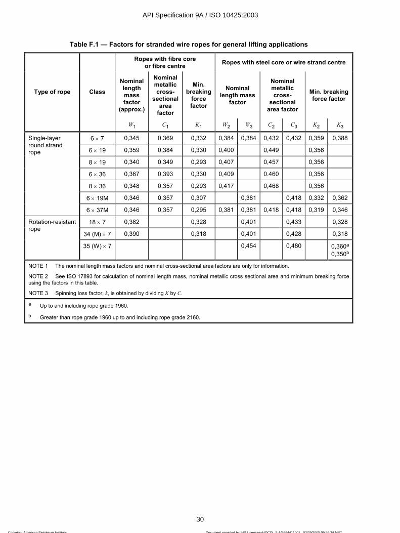
ISO 10425:2003(E)
30 © ISO 2003 — All rights reserved
Table F.1 — Factors for stranded wire ropes for general lifting applications
Ropes with fibre core or fibre centre Ropes with steel core or wire strand centre
Nominal length mass factor
(approx.)
Nominal metallic cross-
sectional area
factor
Min. breaking
force factor
Nominal length mass
factor
Nominal metallic cross-
sectional area factor
Min. breaking force factor
Type of rope Class
W1 C1 K1 W2 W3 C2 C3 K2 K3
6 × 7 0,345 0,369 0,332 0,384 0,384 0,432 0,432 0,359 0,388
6 × 19 0,359 0,384 0,330 0,400 0,449 0,356
8 × 19 0,340 0,349 0,293 0,407 0,457 0,356
6 × 36 0,367 0,393 0,330 0,409 0.460 0,356
8 × 36 0,348 0,357 0,293 0,417 0,468 0,356
6 × 19M 0,346 0,357 0,307 0,381 0,418 0,332 0,362
Single-layer round strand rope
6 × 37M 0,346 0,357 0,295 0,381 0,381 0,418 0,418 0,319 0,346
18 × 7 0,382 0,328 0,401 0,433 0,328
34 (M) × 7 0,390 0,318 0,401 0,428 0,318
Rotation-resistant rope
35 (W) × 7 0,454 0,480 0,360a
0,350b
NOTE 1 The nominal length mass factors and nominal cross-sectional area factors are only for information.
NOTE 2 See ISO 17893 for calculation of nominal length mass, nominal metallic cross sectional area and minimum breaking force using the factors in this table.
NOTE 3 Spinning loss factor, k, is obtained by dividing K by C.
a Up to and including rope grade 1960.
b Greater than rope grade 1960 up to and including rope grade 2160.
API Specification 9A / ISO 10425:2003
30
Copyright American Petroleum Institute Reproduced by IHS under license with API
Document provided by IHS Licensee=HOCOL S A/9984411001, 03/29/2005 09:56:34 MSTQuestions or comments about this message: please call the Document Policy Groupat 303-397-2295.
--`,,`,,```,`,`,,`,,`,``,,`,,``-`-`,,`,,`,`,,`---

ISO 10425:2003(E)
© ISO 2003 — All rights reserved 31
Annex G (normative)
Tables of breaking forces for the more common classes, sizes
and grades of stranded ropes up to and including 60 mm diameter
The following tables give the breaking forces of the more common classes, sizes and grades of stranded ropes up to and including 60 mm diameter.
Higher values of minimum breaking force than those given in the Tables may be guaranteed by the manufacturer.
NOTE 1 The equivalent minimum breaking force values in kilonewtons for rope grades IPS, EIP and EEIP are given for comparison with the minimum breaking force values for grades 1770, 1960 and 2160.
NOTE 2 The conversion factor from short tons to kilonewtons is 8,896.
NOTE 3 The values of nominal length mass are approximate and are given for information.
API Specification 9A / ISO 10425:2003
31
Copyright American Petroleum Institute Reproduced by IHS under license with API
Document provided by IHS Licensee=HOCOL S A/9984411001, 03/29/2005 09:56:34 MSTQuestions or comments about this message: please call the Document Policy Groupat 303-397-2295.
--`,,`,,```,`,`,,`,,`,``,,`,,``-`-`,,`,,`,`,,`---

ISO 10425:2003(E)
32 © ISO 2003 — All rights reserved
Table G.1 — Class 6 ×××× 7 fibre core
Typical cross-section Typical construction
Rope construction Strand construction Outer wires
Total Per strand
6 ×××× 7-FC 1-6 36 6
Nominal rope diameter
Diameter tolerance
Approximate nominal length
mass Minimum breaking force (Fmin)
min. max. Grade 1770 Grade 1960 Grade IPS Grade EIP
mm (in) mm mm kg/100 m (lb/ft) kN kN kN (short tons) kN (short tons)
6 6,00 6,36 12,4 21,2 23,4
(6,35) (1/4) 6,35 6,73 (0.09) 23,5 (2.64) 25,8 (2.90)
7 7,00 7,42 16,9 28,8 31,9
(7,94) (5/16) 7,94 8,42 (0.15) 36,5 (4.10) 40,1 (4.51)
8 8,00 8,40 22,1 37,6 41,6
9 9,00 9,45 27,9 47,6 52,7
(9,5) (3/8) 9,53 10,0 (0.21) 52,1 (5.86) 57,4 (6.45)
10 10,0 10,5 34,5 58,8 65,1
11 11,0 11,6 41,7 71,1 78,7
(11,1) (7/16) 11,1 11,7 (0.29) 70,5 (7.93) 77,6 (8.72)
12 12,0 12,6 49,7 84,6 93,7
(12,7) (1/2) 12,7 13,3 (0.37) 91,6 (10.3) 101 (11.3)
13 13,0 13,7 58,3 99,3
14 14,0 14,7 67,6 115 110
(14,3) (9/16) 14,3 15, 0 (0.47) 128 116 (13.0) 127 (14.3)
(15,9) (5/8) 15,9 16,7 (0.58) 141 (15.9)
16 16,0 16,8 88,3 150 167
18 18,0 18,9 112 190 211
19 19,0 20,0 125 212 235
(19,1) (3/4) 19,1 20,0 202 (22.7) 222 (25.0)
20 20,0 21,0 138 (0.84) 235 260
22 22,0 23,1 167 284 315
(22,2) (7/8) 22,2 23,3 (1.15) 273 (30.7) 301 (33.8)
24 24,0 25,2 199 338 375
(25,4) (1) 25,4 26,7 (1.50) 353 (39.7) 389 (43.7)
26 26,0 27,3 233 397 440
28 28,0 29,4 270 461 510
(28,6) (1-1/8) 28,6 30,0 (1.89) 443 (49.8) 488 (54.8)
(31,8) (1-1/4) 31,8 33,3 (2.34) 543 (61.0) 597 (67.1)
32 32,0 33, 6 353 602 666
(34,9) (1-3/8) 34,9 36,7 (2.83) 650 (73.1) 715 (80.4)
35 35,0 36,8 423 720 797
36 36,0 37,8 447 762 843
38 38,0 39,9 498 849 940
(38,1) (1-1/2) 38,1 40,0 (3.37) 767 (86.2) 843 (94.8)
40 40,0 42,0 552 940 1 040
API Specification 9A / ISO 10425:2003
32
Copyright American Petroleum Institute Reproduced by IHS under license with API
Document provided by IHS Licensee=HOCOL S A/9984411001, 03/29/2005 09:56:34 MSTQuestions or comments about this message: please call the Document Policy Groupat 303-397-2295.
--`,,`,,```,`,`,,`,,`,``,,`,,``-`-`,,`,,`,`,,`---
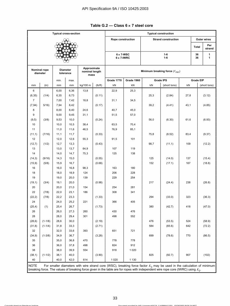
ISO 10425:2003(E)
© ISO 2003 — All rights reserved 33
Table G.2 — Class 6 ×××× 7 steel core
Typical cross-section Typical construction
Rope construction Strand construction Outer wires
Total Per strand
6 ×××× 7-WSC 6 ×××× 7-IWRC
1-6 1-6
36 36
1 1
Nominal rope diameter
Diameter tolerance
Approximate nominal length
mass Minimum breaking force (Fmin)
min. max. Grade 1770 Grade 1960 Grade IPS Grade EIP
mm (in) mm mm kg/100 m (lb/ft) kN kN kN (short tons) kN (short tons)
6 6,00 6,36 13,8 22,9 25,3
(6,35) (1/4) 6,35 6,73 (0.11) 25,3 (2.84) 27,8 (3.12)
7 7,00 7,42 18,8 31,1 34,5
(7,94) 5/16) 7,94 8,42 (0.17) 39,2 (4.41) 43,1 (4.85)
8 8,00 8,40 24,6 40,7 45,0
9 9,00 9,45 31,1 51,5 57,0
(9,5) (3/8) 9,53 10,0 (0.24) 56,0 (6.30) 61,6 (6.93)
10 10,0 10,5 38,4 63,5 70,4
11 11,0 11,6 46,5 76,9 85,1
(11,1) (7/16) 11,1 11,7 (0.33) 75,8 (8.52) 83,4 (9.37)
12 12,0 12,6 55,3 91,5 101
(12,7) (1/2) 12,7 13,3 (0.43) 98,7 (11.1) 109 (12.2)
13 13,0 13,7 64,9 107 119
14 14,0 14,7 75,3 125 138
(14,3) (9/16) 14,3 15,0 (0.55) 125 (14.0) 137 (15.4)
(15,9) (5/8) 15,9 16,7 (0.68) 152 (17.1) 167 (18.8)
16 16,0 16,8 98,3 163 180
18 18,0 18,9 124 206 228
19 19,0 20,0 139 229 254
(19,1) (3/4) 19,1 20,0 (0.98) 217 (24.4) 238 (26.8)
20 20,0 21,0 154 254 281
22 (7/8) 22,0 23,1 186 308 341
(22,2) (7/8) 22,2 23,3 (1.33) 294 (33.0) 323 (36.3)
24 24,0 25,2 221 366 405
(25,4) (1) 25,4 26,7 (1.73) 380 (42.7) 418 (47.0)
26 26,0 27,3 260 430 476
28 28,0 29,4 301 498 552
(28,6) (1-1/8) 28,6 30,0 (2.19) 476 (53.5) 524 (58.9)
(31,8) (1-1/4) 31,8 33,3 (2.71) 584 (65.6) 642 (72.2)
32 32,0 33,6 393 651 721
(34,9) (1-3/8) 34,9 36,7 (3.28) 699 (78.6) 770 (86.5)
35 35,0 36,8 470 778 778
36 36,0 37,8 498 824 912
38 38,0 39,9 554 918 1 020
(38,1) (1-1/2) 38,1 40,0 (3.90) 825 (92.7) 907 (102)
40 40,0 42,0 614 1 020 1 130
NOTE For smaller diameters with wire strand core (WSC), breaking force factor K3 may be used in the calculation of minimum breaking force. The values of breaking force given in the table are for ropes with independent wire rope core (IWRC) using K2.
API Specification 9A / ISO 10425:2003
33
Copyright American Petroleum Institute Reproduced by IHS under license with API
Document provided by IHS Licensee=HOCOL S A/9984411001, 03/29/2005 09:56:34 MSTQuestions or comments about this message: please call the Document Policy Groupat 303-397-2295.
--`,,`,,```,`,`,,`,,`,``,,`,,``-`-`,,`,,`,`,,`---

ISO 10425:2003(E)
34 © ISO 2003 — All rights reserved
Table G.3 — Class 6 ×××× 19M fibre core
Typical cross-section Typical construction
Rope construction Strand construction Outer wires
Total Per strand
6 ×××× 19M-FC 1-6/12 72 12
Nominal rope diameter
Diameter tolerance
Approximate nominal length
mass Minimum breaking force (Fmin)
min. max. Grade 1770 Grade 1960
mm (in) mm mm kg/100 m kN kN
3 3,00 3,24 3,11 4,89 5,42
4 4,00 4,28 5,54 8,69 9,63
5 5,00 5,35 8,65 13,6 15,0
6 6,00 6.36 12,5 19,6 21,7
7 7,00 7,42 17,0 26,6 29,5
8 8,00 8.40 22,1 34,8 38,5
9 9,00 9,45 28,0 44,0 48,7
(9,5) (3/8) 9,53 10,0
10 10,0 10.,5 34,6 54,3 60,2
11 11,0 11,6 41,9 65,8 72,8
(11,1) (7/16) 11,1 11,7
12 12,0 12,6 49,8 78,2 86.6
(12,7) (1/2) 12,7 13,3
13 13,0 13,7 58,5 91,8 102
14 14,0 14,7 67,8 107 118
(14,3) (9/16) 14,3 15,0
(15,9) (5/8) 15,9 16,7
16 16,0 16,8 88,6 139 154
18 18,0 18,9 112 176 195
19 19,0 20,0 125 196 217
(19,1) (3/4) 19,1 20,0
20 20,0 21,0 138 217 241
22 22,0 23,1 167 263 291
(22,2) (7/8) 22,2 23,3
24 24,0 25,2 199 313 347
(25,4) (1) 25,4 26,7
26 26,0 27,3 234 367 407
28 28,0 29,4 271 426 472
(28,6) (1-1/8) 28,6 30,0
(31,8) (1-1/4) 31,8 33,3
32 32,0 33,6 354 556 616
API Specification 9A / ISO 10425:2003
34
Copyright American Petroleum Institute Reproduced by IHS under license with API
Document provided by IHS Licensee=HOCOL S A/9984411001, 03/29/2005 09:56:34 MSTQuestions or comments about this message: please call the Document Policy Groupat 303-397-2295.
--`,,`,,```,`,`,,`,,`,``,,`,,``-`-`,,`,,`,`,,`---

ISO 10425:2003(E)
© ISO 2003 — All rights reserved 35
Table G.4 — Class 6 ×××× 19M steel core
Typical cross-section Typical construction
Rope construction Strand construction Outer wires
Total Per strand
6 ×××× 19M-WSC 1-6/12 72 12
6 ×××× 19M-IWRC 1-6/12 72 12
Nominal rope diameter
Diameter tolerance
Approximate nominal length
mass Minimum breaking force (Fmin)
min. max. Grade 1770 Grade 1960
mm (in) mm mm kg/100m kN kN
8 8,00 8,40 24,7 37,6 41,6
9 9,00 9,45 31,2 47,6 52,7
(9,5) (3/8) 9,53 10,0
10 10,0 10,5 38,6 58,8 65,1
11 11,0 11,6 46,7 71,1 78,7
(11,1) (7/16) 11,1 11,7
12 12,0 12,6 55,6 84,6 93,7
(12,7) (1/2) 12,7 13,3
13 13,0 13,7 65,2 99,3 110
14 14,0 14,7 75,7 115 128
(14,3) (9/16) 14,3 15,0
(15,9) (5/8) 15,9 16,7
16 16,0 16,8 98,8 150 167
18 18,0 18,9 125 190 211
19 19,0 20,0 139 212 235
(19,1) (3/4) 19,1 20,0
20 20,0 21,0 154 235 260
22 22,0 23,1 187 284 315
(22,2) (7/8) 22,2 23,3
24 24,0 25,2 222 338 375
(25,4) (1) 25,4 26,7
26 26,0 27,3 261 397 440
28 28,0 29,4 303 461 510
(28,6) (1-1/8) 28,6 30,0
(31,8) (1-1/4) 31,8 33,3
32 32,0 33,6 395 602 666
NOTE For smaller diameters with wire strand core (WSC), breaking force factor K3 may be used in the calculation of minimum breaking force. The values of breaking force given in the table are for ropes with independent wire rope core (IWRC) using K2.
API Specification 9A / ISO 10425:2003
35
Copyright American Petroleum Institute Reproduced by IHS under license with API
Document provided by IHS Licensee=HOCOL S A/9984411001, 03/29/2005 09:56:34 MSTQuestions or comments about this message: please call the Document Policy Groupat 303-397-2295.
--`,,`,,```,`,`,,`,,`,``,,`,,``-`-`,,`,,`,`,,`---

ISO 10425:2003(E)
36 © ISO 2003 — All rights reserved
Table G.5 — Class 6 ×××× 37M fibre core
Typical cross-section Typical construction
Rope construction Strand construction Outer wires
Total Per strand
6 ×××× 37M-FC 1-6/12/18 108 18
Nominal rope diameter
Diameter tolerance
Approximate nominal length
mass Minimum breaking force (Fmin)
min. max. Grade 1770 Grade 1960
mm (in) mm mm kg/100m kN kN
5 5,00 5,35 8,65 13,9 14,6
6 6,00 6,36 12,5 18,8 20,8
7 7,00 7,42 17,0 25,6 28,3
8 8,00 8,40 22,1 33,4 37,0
9 9,00 9,45 28,0 42,3 46,8
(9,5) (3/8) 9,53 10,0
10 10,0 10,5 34,6 52,2 57,8
11 11,0 11,6 41,9 63,2 70,0
(11,1) (7/16) 11,1 11,7
12 12,0 12,6 49,8 75,2 83,3
(12,7) (1/2) 12,7 13,3
13 13,0 13,7 58,5 88,2 97,7
14 14,0 14,7 67,8 102 113
(14,3) (9/16) 14,3 15,0
(15,9) (5/8) 15,9 16,7
16 16,0 16,8 88,6 134 148
18 18,0 18,9 112 169 187
19 19,0 20,0 125 188 209
(19,1) (3/4) 19,1 20,0
20 20,0 21,0 138 209 231
22 22,0 23,1 167 253 280
(22,2) (7/8) 22,2 23,3
24 24,0 25,2 199 301 333
(25,4) (1) 25,4 26,7
26 26,0 27,3 239 353 391
28 28,0 29,4 271 409 453
(28,6) (1-1/8) 28,6 30,0
(31,8) (1-1/4) 31,8 33,3
32 32,0 33,6 354 535 592
(34,9) (1-3/8) 34,9 36,7
35 35,0 36,8 424 640 708
36 36,0 37,8 448 677 749
38 38,0 39,9 500 754 835
(38,1) (1-1/2) 38,1 40,0
40 40,0 42,0 554 835 925
API Specification 9A / ISO 10425:2003
36
Copyright American Petroleum Institute Reproduced by IHS under license with API
Document provided by IHS Licensee=HOCOL S A/9984411001, 03/29/2005 09:56:34 MSTQuestions or comments about this message: please call the Document Policy Groupat 303-397-2295.
--`,,`,,```,`,`,,`,,`,``,,`,,``-`-`,,`,,`,`,,`---
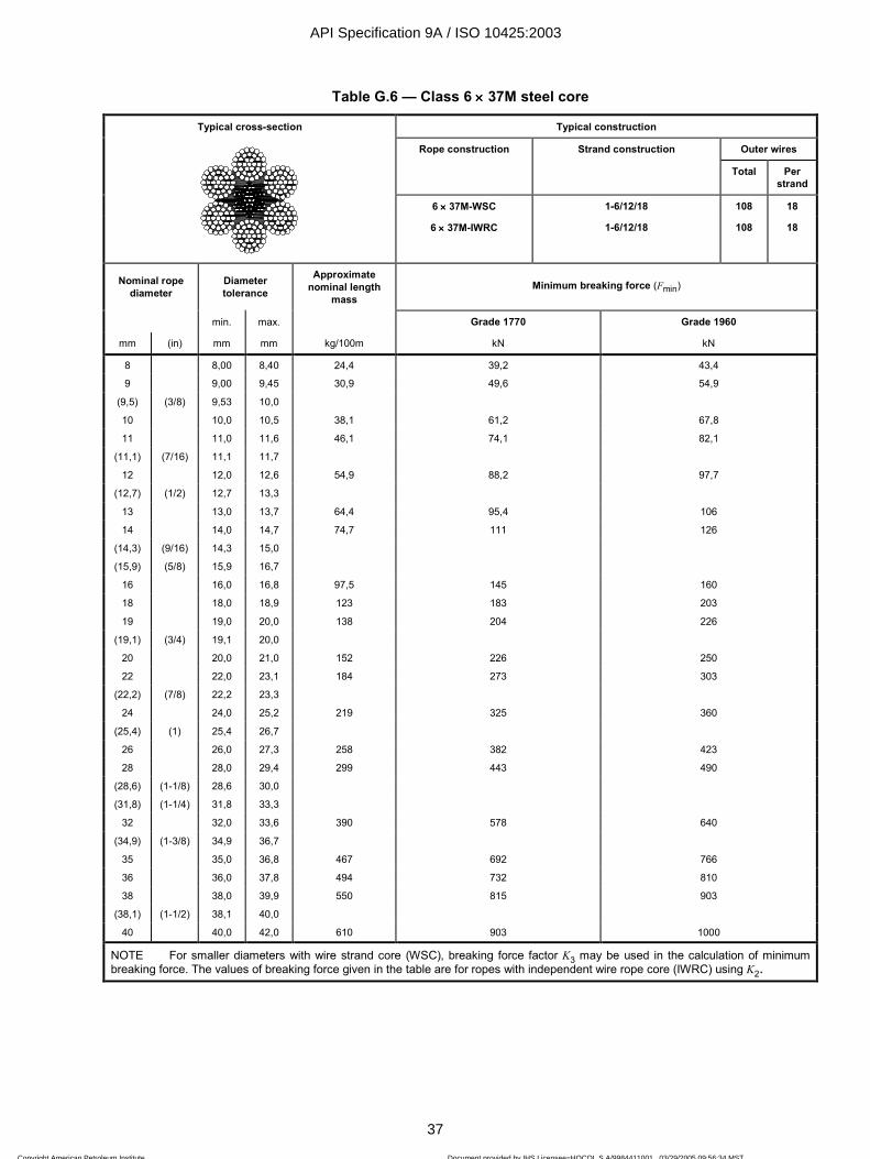
ISO 10425:2003(E)
© ISO 2003 — All rights reserved 37
Table G.6 — Class 6 ×××× 37M steel core
Typical cross-section Typical construction
Rope construction Strand construction Outer wires
Total Per strand
6 ×××× 37M-WSC 1-6/12/18 108 18
6 ×××× 37M-IWRC 1-6/12/18 108 18
Nominal rope diameter
Diameter tolerance
Approximate nominal length
mass Minimum breaking force (Fmin)
min. max. Grade 1770 Grade 1960
mm (in) mm mm kg/100m kN kN
8 8,00 8,40 24,4 39,2 43,4
9 9,00 9,45 30,9 49,6 54,9
(9,5) (3/8) 9,53 10,0
10 10,0 10,5 38,1 61,2 67,8
11 11,0 11,6 46,1 74,1 82,1
(11,1) (7/16) 11,1 11,7
12 12,0 12,6 54,9 88,2 97,7
(12,7) (1/2) 12,7 13,3
13 13,0 13,7 64,4 95,4 106
14 14,0 14,7 74,7 111 126
(14,3) (9/16) 14,3 15,0
(15,9) (5/8) 15,9 16,7
16 16,0 16,8 97,5 145 160
18 18,0 18,9 123 183 203
19 19,0 20,0 138 204 226
(19,1) (3/4) 19,1 20,0
20 20,0 21,0 152 226 250
22 22,0 23,1 184 273 303
(22,2) (7/8) 22,2 23,3
24 24,0 25,2 219 325 360
(25,4) (1) 25,4 26,7
26 26,0 27,3 258 382 423
28 28,0 29,4 299 443 490
(28,6) (1-1/8) 28,6 30,0
(31,8) (1-1/4) 31,8 33,3
32 32,0 33,6 390 578 640
(34,9) (1-3/8) 34,9 36,7
35 35,0 36,8 467 692 766
36 36,0 37,8 494 732 810
38 38,0 39,9 550 815 903
(38,1) (1-1/2) 38,1 40,0
40 40,0 42,0 610 903 1000
NOTE For smaller diameters with wire strand core (WSC), breaking force factor K3 may be used in the calculation of minimum breaking force. The values of breaking force given in the table are for ropes with independent wire rope core (IWRC) using K2.
API Specification 9A / ISO 10425:2003
37
Copyright American Petroleum Institute Reproduced by IHS under license with API
Document provided by IHS Licensee=HOCOL S A/9984411001, 03/29/2005 09:56:34 MSTQuestions or comments about this message: please call the Document Policy Groupat 303-397-2295.
--`,,`,,```,`,`,,`,,`,``,,`,,``-`-`,,`,,`,`,,`---
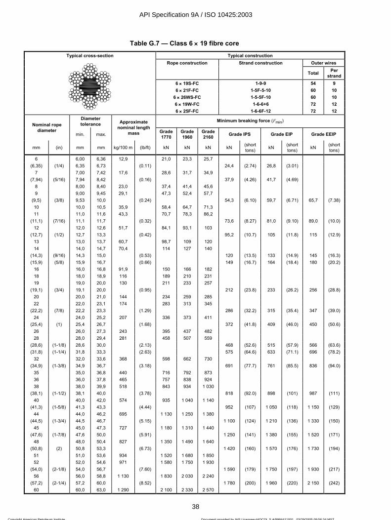
ISO 10425:2003(E)
38 © ISO 2003 — All rights reserved
Table G.7 — Class 6 ×××× 19 fibre core
Typical cross-section Typical construction Rope construction Strand construction Outer wires
Total Per strand
6 ×××× 19S-FC 1-9-9 54 9 6 ×××× 21F-FC 1-5F-5-10 60 10
6 ×××× 26WS-FC 1-5-5F-10 60 10 6 ×××× 19W-FC 1-6-6+6 72 12
6 ×××× 25F-FC 1-6-6F-12 72 12 Diameter tolerance
Minimum breaking force (Fmin) Nominal rope
diameter min. max.
Approximate nominal length
mass Grade 1770
Grade 1960
Grade 2160 Grade IPS Grade EIP Grade EEIP
mm (in) mm mm kg/100 m (lb/ft) kN kN kN kN (short tons) kN (short
tons) kN (short tons)
6 6,00 6,36 12,9 21,0 23,3 25,7 (6,35) (1/4) 6,35 6,73 (0.11) 24,4 (2.74) 26,8 (3.01)
7 7,00 7,42 17,6 28,6 31,7 34,9 (7,94) (5/16) 7,94 8,42 (0.16) 37,9 (4.26) 41,7 (4.69)
8 8,00 8,40 23,0 37,4 41,4 45,6 9 9,00 9,45 29,1 47,3 52,4 57,7
(9,5) (3/8) 9,53 10,0 (0.24) 54,3 (6.10) 59,7 (6.71) 65,7 (7.38) 10 10,0 10,5 35,9 58,4 64,7 71,3 11 11,0 11,6 43,3 70,7 78,3 86,2
(11,1) (7/16) 11,1 11,7 (0.32) 73,6 (8.27) 81,0 (9.10) 89,0 (10.0) 12 12,0 12,6 51,7 84,1 93,1 103
(12,7) (1/2) 12,7 13,3 (0.42) 95,2 (10.7) 105 (11.8) 115 (12.9) 13 13,0 13,7 60,7 98,7 109 120 14 14,0 14,7 70,4 114 127 140
(14,3) (9/16) 14,3 15,0 (0.53) 120 (13.5) 133 (14.9) 145 (16.3) (15,9) (5/8) 15,9 16,7 (0.66) 149 (16.7) 164 (18.4) 180 (20.2)
16 16,0 16,8 91,9 150 166 182 18 18,0 18,9 116 189 210 231 19 19,0 20,0 130 211 233 257
(19,1) (3/4) 19,1 20,0 (0.95) 212 (23.8) 233 (26.2) 256 (28.8) 20 20,0 21,0 144 234 259 285 22 22,0 23,1 174 283 313 345
(22,2) (7/8) 22,2 23,3 (1.29) 286 (32.2) 315 (35.4) 347 (39.0) 24 24,0 25,2 207 336 373 411
(25,4) (1) 25,4 26,7 (1.68) 372 (41.8) 409 (46.0) 450 (50.6) 26 26,0 27,3 243 395 437 482 28 28,0 29,4 281 458 507 559
(28,6) (1-1/8) 28,6 30,0 (2.13) 468 (52.6) 515 (57.9) 566 (63.6) (31,8) (1-1/4) 31,8 33,3 (2.63) 575 (64.6) 633 (71.1) 696 (78.2)
32 32,0 33,6 368 598 662 730 (34,9) (1-3/8) 34,9 36,7 (3.18) 691 (77.7) 761 (85.5) 836 (94.0)
35 35,0 36,8 440 716 792 873 36 36,0 37,8 465 757 838 924 38 38,0 39,9 518 843 934 1 030
(38,1) (1-1/2) 38,1 40,0 (3.78) 818 (92.0) 898 (101) 987 (111) 40 40,0 42,0 574 935 1 040 1 140
(41,3) (1-5/8) 41,3 43,3 (4.44) 952 (107) 1 050 (118) 1 150 (129) 44 44,0 46,2 695 1 130 1 250 1 380
(44,5) (1-3/4) 44,5 46,7 (5.15) 1 100 (124) 1 210 (136) 1 330 (150) 45 45,0 47,3 727 1 180 1 310 1 440
(47,6) (1-7/8) 47,6 50,0 (5.91) 1 250 (141) 1 380 (155) 1 520 (171) 48 48,0 50,4 827 1 350 1 490 1 640
(50,8) (2) 50,8 53,3 (6.73) 1 420 (160) 1 570 (176) 1 730 (194) 51 51,0 53,6 934 1 520 1 680 1 850 52 52,0 54,6 971 1 580 1 750 1 930
(54,0) (2-1/8) 54,0 56,7 (7.60) 1 590 (179) 1 750 (197) 1 930 (217) 56 56,0 58,8 1 130 1 830 2 030 2 240
(57,2) (2-1/4) 57,2 60,0 (8.52) 1 780 (200) 1 960 (220) 2 150 (242) 60 60,0 63,0 1 290 2 100 2 330 2 570
API Specification 9A / ISO 10425:2003
38
Copyright American Petroleum Institute Reproduced by IHS under license with API
Document provided by IHS Licensee=HOCOL S A/9984411001, 03/29/2005 09:56:34 MSTQuestions or comments about this message: please call the Document Policy Groupat 303-397-2295.
--`,,`,,```,`,`,,`,,`,``,,`,,``-`-`,,`,,`,`,,`---
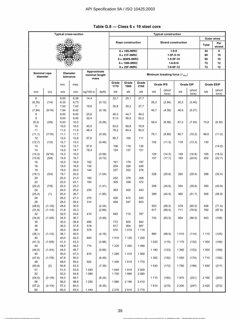
ISO 10425:2003(E)
© ISO 2003 — All rights reserved 39
Table G.8 — Class 6 ×××× 19 steel core
Typical cross-section Typical construction Outer wires
Rope construction Strand construction Total Per
strand 6 ×××× 19S-IWRC 1-9-9 54 9 6 ×××× 21F-IWRC 1-5F-5-10 60 10
6 ×××× 26WS-IWRC 1-5-5F-10 60 10 6 ×××× 19W-IWRC 1-6-6+6 72 12
6 ×××× 25F-IWRC 1-6-6F-12 72 12
Nominal rope diameter
Diameter tolerance
Approximate nominal length
mass Minimum breaking force (Fmin)
min. max. Grade1770
Grade1960
Grade2160 Grade IPS Grade EIP Grade EEIP
mm (in) mm mm kg/100 m (lb/ft) kN kN kN kN (short tons) kN (short
tons) kN (short tons)
6 6,00 6,36 14,4 22,7 25,1 27,7 (6,35) (1/4) 6,35 6,73 (0.12) 26,2 (2.94) 30,2 (3.40)
7 7,00 7,42 19,6 30,9 34,2 37,7 (7,94) (5/16) 7,94 8,42 (0.18) 40,7 (4.58) 46,9 (5.27)
8 8,00 8,40 25,6 40,3 44,7 49,2 9 9,00 9,45 32,4 51,0 56,5 62,2
(9,5) (3/8) 9,53 10,0 (0.26) 58,4 (6.56) 67,2 (7.55) 73,8 (8.30) 10 10,0 10,5 40,0 63,0 69,8 76,9 11 11,0 11,6 48,4 76,2 84,4 93,0
(11,1) (7/16) 11,1 11,7 (0.35) 79,1 (8.89) 90,7 (10.2) 99,6 (11.2) 12 12,0 12,6 57,6 90,7 100 111
(12,7) (1/2) 12,7 13,3 (0.46) 102 (11.5) 118 (13.3) 130 13 13,0 13,7 67,6 106 118 130 (14.6) 14 14,0 14,7 78,4 124 137 151
(14,3) (9/16) 14,3 15,0 (0.58) 129 (14.5) 149 (16.8) 165 (18.5) (15,9) (5/8) 15,9 16,7 (0.72) 157 (17.7) 183 (20.6) 202 (22.7)
16 16,0 16,8 102 161 179 197 18 18,0 18,9 130 204 226 249 19 19,0 20,0 144 227 252 278
(19,1) (3/4) 19,1 20,0 (1.04) 228 (25.6) 262 (29.4) 288 (32.4) 20 20,0 21,0 160 252 279 308 22 22,0 23,1 194 305 338 372
(22,2) (7/8) 22,2 23,3 (1.41) 308 (34.6) 354 (39.8) 390 (43.8) 24 24,0 25,2 230 363 402 443
(25,4) (1) 25,4 26,7 (1.85) 399 (44.9) 460 (51.7) 506 (56.9) 26 26,0 27,3 270 426 472 520 28 28,0 29,4 314 494 547 603
(28,6) (1-1/8) 28,6 30,0 (2.34) 503 (56.5) 578 (65.0) 636 (71.5) (31,8) (1-1/4) 31,8 33,3 (2.89) 617 (69.4) 711 (79.9) 782 (87.9)
32 32,0 33,6 410 645 715 787 (34,9) (1-3/8) 34,9 36,7 (3.49) 743 (83.5) 854 (96.0) 943 (106)
35 35,0 36,8 490 772 855 942 36 36,0 37,8 518 817 904 997 38 38,0 39,9 578 910 1 010 1 110
(38,1) (1-1/2) 38,1 40,0 (4.16) 880 (98.9) 1 010 (114) 1 110 (125) 40 40,0 42,0 640 1 010 1 120 1 230
(41,3) (1-5/8) 41,3 43,3 (4.88) 1 020 (115) 1 170 (132) 1 300 (146) 44 44,0 46,2 774 1 220 1 350 1 490
(44,5) (1-3/4) 44,5 46,7 (5.66) 1 180 (133) 1 360 (153) 1 500 (169) 45 45,0 47,3 810 1 280 1 410 1 560
(47,6) (1-7/8) 47,6 50,0 (6.49) 1 350 (152) 1 550 (174) 1 710 (192) 48 48,0 50,4 922 1 450 1 610 1 770
(50,8) (2) 50,8 53,3 (7.39) 1 530 (172) 1 760 (198) 1 930 (217) 51 51,0 53,6 1 040 1 640 1 810 2 000 52 52,0 54,6 1 080 1 700 1 890 2 080
(54,0) (2-1/8) 54,0 56,7 (8.34) 1 710 (192) 1 970 (221) 2 160 (243) 56 56,0 58,8 1 250 1 980 2 190 2 410
(57,2) (2-1/4) 57,2 60,0 (9.35) 1 910 (215) 2 200 (247) 2 420 (272) 60 60,0 63,0 1 440 2 270 2 510 2 770
API Specification 9A / ISO 10425:2003
39
Copyright American Petroleum Institute Reproduced by IHS under license with API
Document provided by IHS Licensee=HOCOL S A/9984411001, 03/29/2005 09:56:34 MSTQuestions or comments about this message: please call the Document Policy Groupat 303-397-2295.
--`,,`,,```,`,`,,`,,`,``,,`,,``-`-`,,`,,`,`,,`---

ISO 10425:2003(E)
40 © ISO 2003 — All rights reserved
Table G.9 — Class 6 ×××× 36 fibre core
Typical cross-section Typical construction Outer wires
Rope construction Strand construction Total Per
strand 6 ×××× 31WS-FC 1-6-6+6-12 72 12 6 ×××× 36WS-FC 1-7-7+7-14 84 14 6 ×××× 41WS-FC 1-8-8+8-16 96 16 6 ×××× 41SF-FC 1-8-8-8F-16 96 16
6 ×××× 49SWS-FC 1-8-8-8+8-16 96 16 6 ×××× 46WS-FC 1-9-9+9-18 108 18
Nominal rope diameter
Diameter tolerance
Approximate nominal length
mass Minimum breaking force (Fmin)
min. max. Grade 1770
Grade 1960
Grade 2160 Grade IPS Grade EIP Grade EEIP
mm (in) mm mm kg/100 m (lb/ft) kN kN kN kN (short tons) kN (short
tons) kN (short tons)
(6,35) (1/4) 6,35 6,73 (0.11) 24,4 (2.74) 26,8 (3.01) 7 7,00 7,42 18,0 28,6 31,7 34,9
(7,94) (5/16) 7,94 8,42 (0.16) 37,9 (4.26) 41,7 (4.69) 8 8,00 8,40 23,5 37,4 41,4 45,6 9 9,00 9,45 29,7 47,3 52,4 57,7
(9,5) (3/8) 9,53 10,0 (0.24) 54,3 (6.10) 59,7 (6.71) 65,7 (7.38) 10 10,0 10,5 36,7 58,4 64,7 71,3 11 11,0 11,6 44,4 70,7 78,3 86,2
(11,1) (7/16) 11,1 11,7 (0.32) 73,6 (8.27) 81,0 (9.10) 89,0 (10.0) 12 12,0 12,6 52,8 84,1 93,1 103
(12,7) (1/2) 12,7 13,3 (0.42) 95,2 (10.7) 105 (11.8) 115 (12.9) 13 13,0 13,7 62,0 98,7 109 120 14 14,0 14,7 71,9 114 127 140
(14,3) (9/16) 14,3 15,0 (0.53) 120 (13.5) 133 (14.9) 145 (16.3) (15,9) (5/8) 15,9 16,7 (0.66) 149 (16.7) 164 (18.4) 180 (20.2)
16 16,0 16,8 94,0 150 166 182 18 18,0 18,9 119 189 210 231 19 19,0 20,0 132 211 233 257
(19,1) (3/4) 19,1 20,0 (0.95) 212 (23.8) 233 (26.2) 256 (28.8) 20 20,0 21,0 147 234 259 285 22 22,0 23,1 178 283 313 345
(22,2) (7/8) 22,2 23,3 (1.29) 286 (32.2) 315 (35.4) 347 (39.0) 24 24,0 25,2 211 336 373 411
(25,4) (1) 25,4 26,7 (1.68) 372 (41.8) 409 (46.0) 450 (50.6) 26 26,0 27,3 248 395 437 482 28 28,0 29,4 288 458 507 559
(28,6) (1-1/8) 28,6 30,0 (2.13) 468 (52.6) 515 (57.9) 566 (63.6) (31,8) (1-1/4) 31,8 33,3 (2.63) 575 (64.6) 633 (71.1) 696 (78.2)
32 32,0 33,6 376 598 662 730 (34,9) (1-3/8) 34,9 36,7 (3.18) 691 (77.7) 761 (85.5) 836 (94.0)
35 35,0 36,8 450 716 792 873 36 36,0 37,8 476 757 838 924 38 38,0 39,9 530 843 934 1 030
(38,1) (1-1/2) 38,1 40,0 (3.78) 818 (92.0) 898 (101) 987 (111) 40 40,0 42,0 587 935 1 040 1 140
(41,3) (1-5/8) 41,3 43,3 (4.44) 952 (107) 1 050 (118) 1 150 (129) 44 44,0 46,2 711 1 130 1 250 1 380
(44,5) (1-3/4) 44,5 46,7 (5.15) 1 100 (124) 1 210 (136) 1 330 (150) 45 45,0 47,3 743 1 180 1 310 1 440
(47,6) (1-7/8) 47,6 50,0 (5.91) 1 250 (141) 1 380 (155) 1 520 (171) 48 48,0 50,4 846 1 350 1 490 1 640
(50,8) (2) 50,8 53,3 (6.73) 1 420 (160) 1 570 (176) 1 730 (194) 51 51,0 53,6 955 1 520 1 680 1 850 52 52,0 54,6 992 1 580 1 750 1 930
(54,0) (2-1/8) 54,0 56,7 (7.60) 1 590 (179) 1 750 (197) 1 930 (217) 56 56,0 58,8 1 150 1 830 2 030 2 240
(57,2) (2-1/4) 57,2 60,0 (8.52) 1 780 (200) 1 960 (220) 2 150 (242) 60 60,0 63,0 1 320 2 100 2 330 2 570
API Specification 9A / ISO 10425:2003
40
Copyright American Petroleum Institute Reproduced by IHS under license with API
Document provided by IHS Licensee=HOCOL S A/9984411001, 03/29/2005 09:56:34 MSTQuestions or comments about this message: please call the Document Policy Groupat 303-397-2295.
--`,,`,,```,`,`,,`,,`,``,,`,,``-`-`,,`,,`,`,,`---

ISO 10425:2003(E)
© ISO 2003 — All rights reserved 41
Table G.10 — Class 6 ×××× 36 steel core
Typical cross-section Typical construction Outer wires
Rope construction Strand construction Total Per
strand 6 ×××× 31WS-IWRC 1-6-6+6-12 72 12 6 ×××× 36WS-IWRC 1-7-7+7-14 84 14 6 ×××× 41WS-IWRC 1-8-8+8-16 96 16 6 ×××× 41SF-IWRC 1-8-8-8F-16 96 16
6 ×××× 49SWS-IWRC 1-8-8-8+8-16 96 16 6 ×××× 46WS-IWRC 1-9-9+9-18 108 18
Nominal rope diameter
Diameter tolerance
Approximate nominal length
mass Minimum breaking force (Fmin)
min. max. Grade1770
Grade 1960
Grade 2160 Grade IPS Grade EIP Grade EEIP
mm (in) mm mm kg/100 m (lb/ft) kN kN kN kN (short tons) kN (short
tons) kN (short tons)
(6,35) (1/4) 6,35 6,73 (0.12) 26,2 (2.94) 30,2 (3.40) 7 7,00 7,42 20,0 30,9 34,2 37,7
(7,94) (5/16) 7,94 8,42 (0.18) 40,7 (4.58) 46,9 (5.27) 8 8,00 8,40 26,2 40,3 44,7 49,2 9 9,00 9,45 33,1 51,0 56,5 62,2
(9,5) (3/8) 9,53 10,0 (0.26) 58,4 (6.56) 67,2 (7.55) 73,8 (8.30) 10 10,0 10,5 40,9 63,0 69,8 76,9 11 11,0 11,6 49,5 76,2 84,4 93,0
(11,1) (7/16) 11,1 11,7 (0.35) 79,1 (8.89) 90,7 (10.2) 99,6 (11.2) 12 12,0 12,6 58,9 90,7 100 111
(12,7) (1/2) 12,7 13,3 (0.46) 102 (11.5) 118 (13.3) 130 (14.6) 13 13,0 13,7 69,1 106 118 130 14 14,0 14,7 80,2 124 137 151
(14,3) (9/16) 14,3 15,0 (0.58) 129 (14.5) 149 (16.8) 165 (18.5) (15,9) (5/8) 15,9 16,7 (0.72) 157 (17.7) 183 (20.6) 202 (22.7)
16 16,0 16,8 105 161 179 197 18 18,0 18,9 133 204 226 249 19 19,0 20,0 148 227 252 278
(19,1) (3/4) 19,1 20,0 (1.04) 228 (25.6) 262 (29.4) 288 20 20,0 21,0 164 252 279 308 (32.4) 22 22,0 23,1 198 305 338 372
(22,2) (7/8) 22,2 23,3 (1.41) 308 (34.6) 354 (39.8) 390 (43.8) 24 24,0 25,2 236 363 402 443
(25,4) (1) 25,4 26,7 (1.85) 399 (44.9) 460 (51.7) 506 (56.9) 26 26,0 27,3 276 426 472 520 28 28,0 29,4 321 494 547 603
(28,6) (1-1/8) 28,6 30,0 (2.34) 503 (56.5) 578 (65.0) 636 (71.5) (31,8) (1-1/4) 31,8 33,3 (2.89) 617 (69.4) 711 (79.9) 782 (87.9)
32 32,0 33,6 419 645 715 787 (34,9) (1-3/8) 34,9 36,7 (3.49) 743 (83.5) 854 (96.0) 943 (106)
35 35,0 36,8 501 772 855 942 36 36,0 37,8 530 817 904 997 38 38,0 39,9 591 910 1 010 1 110
(38,1) (1-1/2) 38,1 40,0 (4.16) 880 (98.9) 1 010 (114) 1 110 (125) 40 40,0 42,0 654 1 010 1 120 1 230
(41,3) (1-5/8) 41,3 43,3 (4.88) 1 020 (115) 1 170 (132) 1 300 (146) 44 44,0 46,2 792 1 220 1 350 1 490
(44,5) (1-3/4) 44,5 46,7 (5.66) 1 180 (133) 1 360 (153) 1 500 (169) 45 45,0 47,3 828 1 280 1 410 1 560
(47,6) (1-7/8) 47,6 50,0 (6.49) 1 350 (152) 1 550 (174) 1 710 (192) 48 48,0 50,4 942 1 450 1 610 1 770
(50,8) (2) 50,8 53,3 (7.39) 1 530 (172) 1 760 (198) 1 930 (217) 51 51,0 53,6 1 060 1 640 1 810 2 000 52 52,0 54,6 1 110 1 700 1 890 2 080
(54,0) (2-1/8) 54,0 56,7 (8.34) 1 710 (192) 1 970 (221) 2 160 (243) 56 56,0 58,8 1 280 1 980 2 190 2 410
(57,2) (2-1/4) 57,2 60,0 (9.35) 1 910 (215) 2 200 (247) 2 420 (272) 60 60,0 63,0 1 470 2 270 2 510 2 770
API Specification 9A / ISO 10425:2003
41
Copyright American Petroleum Institute Reproduced by IHS under license with API
Document provided by IHS Licensee=HOCOL S A/9984411001, 03/29/2005 09:56:34 MSTQuestions or comments about this message: please call the Document Policy Groupat 303-397-2295.
--`,,`,,```,`,`,,`,,`,``,,`,,``-`-`,,`,,`,`,,`---

ISO 10425:2003(E)
42 © ISO 2003 — All rights reserved
Table G.11 — Class 8 ×××× 19 steel core
Typical cross-section Typical construction Outer wires
Rope construction Strand construction Total Per
strand 8 ×××× 19S-IWRC 1-9-9 72 9 8 ×××× 21F-IWRC 1-5F-5-10 80 10
8 ×××× 26WS-IWRC 1-5-5+5-10 80 10 8 ×××× 19W-IWRC 1-6-6+6 96 12
8 ×××× 25F-IWRC 1-6-6F-12 96 12
Nominal rope diameter
Diameter tolerance
Approximate nominal length
mass Minimum breaking force (Fmin)
min. max. Grade 1770
Grade 1960
Grade 2160 Grade IPS Grade EIP Grade EEIP
mm (in) mm mm kg/ 100 m (lb/ft) kN kN kN kN (short
tons) kN (short tons) kN (short
tons)
(6,35) (1/4) 6,35 6,73 (0.12) 26,2 (2.94) 30,2 (3.40) 7 7,00 7,42 19,9 30,9 34,2 37,7
(7,94) (5/16) 7,94 8,42 (0.19) 40,7 (4.58) 46,9 (5.27) 8 8,00 8,40 26,0 40,3 44,7 49,2 9 9,00 9,45 33,0 51,0 56,5 93,0
(9,5) (3/8) 9,53 10,0 (0.27) 58,4 (6.56) 67,2 (7.55) 73,8 (8.30) 10 10,0 10,5 40,7 63,0 69,8 76,9 11 11,0 11,6 49,2 76,2 84,4 93,0
(11,1) (7/16) 11,1 11,7 (0.37) 79,1 (8.89) 90,7 (10.2) 99,6 (11.2) 12 12,0 12,6 58,6 90,7 100 111
(12,7) (1/2) 12,7 13,3 (0.48) 102 (11.5) 118 (13.3) 130 (14.6) 13 13,0 13,7 68,8 106 118 130 14 14,0 14,7 79,8 124 137 151
(14,3) (9/16) 14,3 15,0 (0.61) 129 (14.5) 149 (16.8) 165 (18.5) (15,9) (5/8) 15,9 16,7 (0.76) 157 (17.7) 183 (20.6) 202 (22.7)
16 16,0 16,8 104 161 179 197 18 18,0 18,9 132 204 226 249 19 19,0 20,0 147 227 252 278
(19,1) (3/4) 19,1 20,0 (1.09) 228 (25.6) 262 (29.4) 288 (32.4) 20 20,0 21,0 163 252 279 308 22 22,0 23,1 197 305 338 372
(22,2) (7/8) 22,2 23,3 (1.48) 308 (34.6) 354 (39.8) 390 (43.8) 24 24,0 25,2 234 363 402 443
(25,4) (1) 25,4 26,7 (1.93) 399 (44.9) 460 (51.7) 506 (56.9) 26 26,0 27,3 275 426 472 520 28 28,0 29,4 319 494 547 603
(28,6) (1-1/8) 28,6 30,0 (2.45) 503 (56.5) 578 (65.0) 636 (71.5) (31,8) (1-1/4) 31,8 33,3 (3.02) 617 (69.4) 711 (79.9) 782 (87.9)
32 32,0 33,6 417 645 715 787 (34,9) (1-3/8) 34,9 36,7 (3.66) 743 (83.5) 854 (96.0) 943 (106)
35 35,0 36,8 499 772 855 942 36 36,0 37,8 527 817 904 997 38 38,0 39,9 588 910 1 010 1 110
(38,1) (1-1/2) 38,1 40,0 (4.35) 880 (98.9) 1 010 (114) 1 110 (125) 40 40,0 42,0 651 1 010 1 120 1 230
(41,3) 41,3 43,3 (5.11) 1 020 (115) 1 170 (132) 1 300 (146) 44 (1-5/8) 44,0 46,2 788 1 220 1 350 1 490
(44,5) 44,5 46,7 (5.95) 1 180 (133) 1 360 (153) 1 500 (169) 45 (1-3/4) 45,0 47,3 824 1 280 1 410 1 560
(47,6) (1-7/8) 47,6 50,0 (6.80) 1 350 (152) 1 550 (174) 1 710 (192) 48 48,0 50,4 938 1 450 1 610 1 770
(50,8) (2) 50,8 53,3 (7.73) 1 530 (172) 1 760 (198) 1 930 (217) 51 51,0 53,6 1 060 1 640 1 810 2 000 52 52,0 54,6 1 100 1 700 1 890 2 080
(54,0) (2-1/8) 54,0 56,7 (8.73) 1 710 (192) 1 970 (221) 2 160 (243) 56 56,0 58,8 1 280 1 980 2 190 2 410
(57,2) (2-1/4) 57,2 60,0 (9.79) 1 910 (215) 2 200 (247) 2 420 (272) 60 60,0 63,0 1 470 2 270 2 510 2 770
API Specification 9A / ISO 10425:2003
42
Copyright American Petroleum Institute Reproduced by IHS under license with API
Document provided by IHS Licensee=HOCOL S A/9984411001, 03/29/2005 09:56:34 MSTQuestions or comments about this message: please call the Document Policy Groupat 303-397-2295.
--`,,`,,```,`,`,,`,,`,``,,`,,``-`-`,,`,,`,`,,`---

ISO 10425:2003(E)
© ISO 2003 — All rights reserved 43
Table G.12 — Class 8 ×××× 36 steel core
Typical cross-section Typical construction Outer wires
Rope construction Strand construction Total Per
strand 8 ×××× 31WS-IWRC 1-6-6+6-12 8 ×××× 36WS-IWRC 1-7-7+7-14
8 ×××× 41WS-IWRC 1-8-8+8-16
Nominal rope diameter
Diameter tolerance
Approximate nominal length
mass Minimum breaking force (Fmin)
min. max. Grade1770
Grade 1960
Grade 2160 Grade IPS Grade EIP Grade EEIP
mm (in) mm mm kg/100 m (lb/ft) kN kN kN kN (short tons) kN (short
tons) kN (short tons)
8 8,00 8,40 26,7 40,3 44,7 49,2 9 9,00 9,45 33,8 51,0 56,5 62,2
(9,5) (3/8) 9,53 10,0 (0.27) 58,4 (6.56) 67,2 (7.55) 73,8 (8.30) 10 10,0 10,5 41,7 63,0 69,8 76,9 11 11,0 11,6 50,5 76,2 84,4 93,0
(11,1) (7/16) 11,1 11,7 (0.37) 79,1 (8.89) 90,7 (10.2) 99,6 (11.2) 12 12,0 12,6 60,0 90,7 100 111
(12,7) (1/2) 12,7 13,3 (0.48) 102 (11.5) 118 (13.3) 130 (14.6) 13 13,0 13,7 70,5 106 118 130 14 14,0 14,7 81,7 124 137 151
(14,3) (9/16) 14,3 15,0 (0.61) 129 (14.5) 149 (16.8) 165 (18.5) (15,9) (5/8) 15,9 16,7 (0.76) 157 (17.7) 183 (20.6) 202 (22.7)
16 16,0 16,8 107 161 179 197 18 18,0 18,9 135 204 226 249 19 19,0 20,0 151 227 252 278
(19,1) (3/4) 19,1 20,0 (1.09) 228 (25.6) 262 (29.4) 288 (32.4) 20 20,0 21,0 167 252 279 308 22 22,0 23,1 202 305 338 372
(22,2) (7/8) 22,2 23,3 (1.48) 308 (34.6) 354 (39.8) 390 (43.8) 24 24,0 25,2 240 363 402 443
(25,4) (1) 25,4 26,7 (1.93) 399 (44.9) 460 (51.7) 506 (56.9) 26 26,0 27,3 282 426 472 520 28 28,0 29,4 327 494 547 603
(28,6) (1-1/8) 28,6 30,0 (2.45) 503 (56.5) 578 (65.0) 636 (71.5) (31,8) (1-1/4) 31,8 33,3 (3.02) 617 (69.4) 711 (79.9) 782 (87.9)
32 32,0 33,6 427 645 715 787 (34,9) (1-3/8) 34,9 36,7 (3.66) 743 (83.5) 854 (96.0) 943 (106)
35 35,0 36,8 511 772 855 942 36 36,0 37,8 540 817 904 997 38 38,0 39,9 602 910 1 010 1 110
(38,1) (1-1/2) 38,1 40,0 (4.35) 880 (98.9) 1 010 (114) 1 110 (125) 40 40,0 42,0 667 1 010 1 120 1 230
(41,3) (1-5/8) 41,3 43,3 (5.11) 1 020 (115) 1 170 (132) 1 300 (146) 44 44,0 46,2 807 1 220 1 350 1 490
(44,5) (1-3/4) 44,5 46,7 (5.92) 1 180 (133) 1 360 (153) 1 500 (169) 45 45,0 47,3 844 1 280 1 410 1 560
(47,6) (1-7/8) 47,6 50,0 (6.80) 1 350 (152) 1 550 (174) 1 710 (192) 48 48,0 50,4 961 1 450 1 610 1 770
(50,8) (2) 50,8 53,3 (7.73) 1 530 (172) 1 760 (198) 1 930 (217) 51 51,0 53,6 1 080 1 640 1 810 2 000 52 52,0 54,6 1 130 1 700 1 890 2 080
(54,0) (2-1/8) 54,0 56,7 (8.73) 1 710 (192) 1 970 (221) 2 160 (243) 56 56,0 58,8 1 310 1 980 2 190 2 410
(57,2) (2-1/4) 57,2 60,0 (9.79) 1 910 (215) 2 200 (247) 2 420 (272) 60 60,0 63,0 1 500 2 270 2 510 2 770
API Specification 9A / ISO 10425:2003
43
Copyright American Petroleum Institute Reproduced by IHS under license with API
Document provided by IHS Licensee=HOCOL S A/9984411001, 03/29/2005 09:56:34 MSTQuestions or comments about this message: please call the Document Policy Groupat 303-397-2295.
--`,,`,,```,`,`,,`,,`,``,,`,,``-`-`,,`,,`,`,,`---

ISO 10425:2003(E)
44 © ISO 2003 — All rights reserved
Table G.13 — Class 18 ×××× 7
Typical cross-section Typical construction Outer wires
Rope construction Strand construction Total Per
strand 17 ×××× 7-FC 1-6 66 6
17 ×××× 7-WSC 1-6 66 6
18 ×××× 7-FC 1-6 72 6 18 ×××× 7-WSC 1-6 72 6
Nominal rope diameter
Diameter tolerance Approximate nominal length mass Minimum breaking force (Fmin)
min. max. Core — FC Core — WSC Grade 1770
Grade 1960 Grade IPS Grade EIP
mm (in) mm mm kg/100 m (lb/ft) kg/100 m (lb/ft) kN kN kN (short tons) kN (short
tons)
6 6,00 6,36 13,8 14,4 20,9 23,1
(6,35) (1/4) 6,35 6,73 (0.11) (0,11) 22,3 (2.51) 24,6 (2.77)
7 7,00 7,42 18,7 19,6 28,4 31,5
(7,94) (5/16) 7,94 8,42 (0.17) (0,18) 34,7 (3.90) 38,3 (4.30)
8 8,00 8,40 24,4 25,7 37,2 41,1
9 9,00 9,45 30,9 32,5 47,0 52,1
(9,5) (3/8) 9,53 10,0 (0.24) (0,26) 49,7 (5.59) 54,5 (6.15)
10 10,0 10,5 38,2 40,1 58,1 64,3
11 11,0 11,6 46,2 48,5 70,2 77,8
(11,1) (7/16) 11,1 11,7 (0.33) (0,35) 67,4 (7.58) 73,9 (8.33)
12 12,0 12,6 55,0 57,7 83,6 92,6
(12,7) (1/2) 12,7 13,3 (0.43) (0,45) 87,6 (9.85) 95,8 (10.8)
13 13,0 13,7 64,6 67,8 98,1 109
14 14,0 14,7 74,9 78,6 114 126
(14,3) (9/16) 14,3 15,0 (0.55) (0,57) 110 (12.4) 121 (13.6)
(15,9) (5/8) 15,9 16,7 (0.68) (0,71) 136 (15.3) 149 (16.8)
16 16,0 16,8 97,8 103 149 165
18 18,0 18,9 124 130 188 208
19 19,0 20,0 138 145 210 232
(19,1) (3/4) 19,1 20,0 (0.97) (1,02) 194 (21.8) 214 (24.0)
20 20,0 21,0 153 160 232 257
22 22,0 23,1 185 194 281 311
(22,2) (7/8) 22,2 23,3 (1.32) (1,39) 262 (29.5) 289 (32.5)
24 24,0 25,2 220 231 334 370
(25,4) (1) 25,4 26,7 (1.73) (1,82) 341 (38.3) 375 (42.2)
26 26,0 27,3 258 271 392 435
28 28,0 29,4 299 314 455 504
(28,6) (1-1/8) 28,6 30,0 (2.19) (2,30) 429 (48.2) 472 (53.1)
(31,8) (1-1/4) 31,8 33,3 (2.70) (2,84) 527 (59.2) 579 (65.1)
32 32,0 33,6 391 411 594 658
(34,9) (1-3/8) 34,9 36,7 (3.27) (3,43) 634 (71.3) 697 (78.4)
35 35,0 36,8 468 491 711 788
36 36,0 37,8 495 520 752 833
38 38,0 39,9 552 579 838 928
(38,1) (1-1/2) 38,1 40,0 (3.89) (4,09) 751 (84.4) 826 (92.8)
API Specification 9A / ISO 10425:2003
44
Copyright American Petroleum Institute Reproduced by IHS under license with API
Document provided by IHS Licensee=HOCOL S A/9984411001, 03/29/2005 09:56:34 MSTQuestions or comments about this message: please call the Document Policy Groupat 303-397-2295.
--`,,`,,```,`,`,,`,,`,``,,`,,``-`-`,,`,,`,`,,`---

ISO 10425:2003(E)
© ISO 2003 — All rights reserved 45
Table G.14 — Class 34(M) ×××× 7
Typical cross-section Typical construction Outer wires
Rope construction Strand construction Total Per
strand
34(M) ×××× 7-FC 1-6 102 6
34(M) ×××× 7-WSC 1-6 102 6
36(M) ×××× 7-FC 1-6 108 6 36(M) ×××× 7-WSC 1-6 108 6
Nominal rope diameter
Diameter tolerance Approximate nominal length mass Minimum breaking force (Fmin)
min. max. Core — FC Core — WSC Grade 1770
Grade 1960 Grade IPS Grade EIP
mm (in) mm mm kg/100 m (lb/ft) kg/100 m (lb/ft) kN kN kN (short tons) kN (short
tons)
10 10,0 10,5 39,0 40,1 56,3 62,3
11 11,0 11,6 47,2 48,5 68,1 75,4
(11,1) (7/16) 11,1 11,7 (0.32) (0.33) 69,5 (7.81) 77,0 (8.65)
12 12,0 12,6 56,2 57,7 81,1 89,8
(12,7) (1/2) 12,7 13,3 (0.42) (0.43) 90,7 (10.2) 101 (11.3)
13 13,0 13,7 65,9 67,8 95,1 105
14 14,0 14,7 76,4 78,6 110 122
(14,3) (9/16) 14,3 15,0 (0.53) (0.55) 115 (12.9) 127 (14.3)
(15,9) (5/8) 15,9 16,7 (0.66) (0.68) 141 (15.9) 157 (17.7)
16 16,0 16,8 99,8 103 144 160
18 18,0 18,9 126 130 182 202
19 19,0 20,0 141 145 203 225
(19,1) (3/4) 19,1 20,0 (0.95) (0.98) 205 (23.0) 226 (25.4)
20 20,0 21,0 156 160 225 249
22 22,0 23,1 189 194 272 302
(22,2) (7/8) 22,2 23,3 (1.29) (1.33) 278 (31.3) 308 (34.6)
24 24,0 25,2 225 231 324 359
(25,4) (1) 25,4 26,7 (1.69) (1.74) 363 (40.8) 402 (45.2)
26 26,0 27,3 264 271 380 421
28 28,0 29,4 306 314 441 489
(28,6) (1-1/8) 28,6 30,0 (2.14) (2.20) 460 (51.7) 509 (57.2)
(31,8) (1-1/4) 31,8 33,3 (2.64) (2.72) 568 (63.8) 628 (70.6)
32 32,0 33,6 399 411 576 638
(34,9) (1-3/8) 34,9 36,7 (3.20) (3.29) 687 (77.2) 761 (85.5)
35 35,0 36,8 478 491 690 764
36 36,0 37,8 505 520 729 808
38 38,0 39,9 563 579 813 900
(38,1) (1-1/2) 38,1 40,0 (3.80) (3.91) 817 (91.8) 907 (102)
40 40,0 42,0 624 901 997 (119)
(41,3) (1-5/8) 41,3 43,4 (4.46) (4.59) 961 (108) 1 060
44 44,0 46,2 755 1 090 1 210
API Specification 9A / ISO 10425:2003
45
Copyright American Petroleum Institute Reproduced by IHS under license with API
Document provided by IHS Licensee=HOCOL S A/9984411001, 03/29/2005 09:56:34 MSTQuestions or comments about this message: please call the Document Policy Groupat 303-397-2295.
--`,,`,,```,`,`,,`,,`,``,,`,,``-`-`,,`,,`,`,,`---
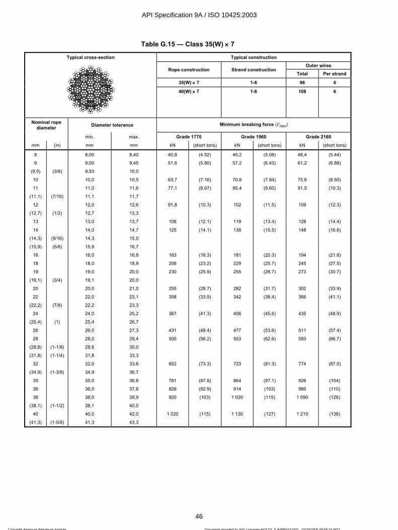
ISO 10425:2003(E)
46 © ISO 2003 — All rights reserved
Table G.15 — Class 35(W) ×××× 7
Typical cross-section Typical construction Outer wires
Rope construction Strand construction Total Per strand
35(W) ×××× 7 1-6 96 6
40(W) ×××× 7 1-6 108 6
Nominal rope diameter Diameter tolerance Minimum breaking force (Fmin)
min. max. Grade 1770 Grade 1960 Grade 2160
mm (in) mm mm kN (short tons) kN (short tons) kN (short tons)
8 8,00 8,40 40,8 (4.52) 45,2 (5.08) 48,4 (5.44)
9 9,00 9,45 51,6 (5.80) 57,2 (6.43) 61,2 (6.88)
(9,5) (3/8) 9,53 10,0
10 10,0 10,5 63,7 (7.16) 70,6 (7.94) 75,6 (8.50)
11 11,0 11,6 77,1 (8.67) 85,4 (9.60) 91,5 (10.3)
(11,1) (7/16) 11,1 11,7
12 12,0 12,6 91,8 (10.3) 102 (11.5) 109 (12.3)
(12,7) (1/2) 12,7 13,3
13 13,0 13,7 108 (12.1) 119 (13.4) 128 (14.4)
14 14,0 14,7 125 (14.1) 138 (15.5) 148 (16.6)
(14,3) (9/16) 14,3 15,0
(15,9) (5/8) 15,9 16,7
16 16,0 16,8 163 (18.3) 181 (20.3) 194 (21.8)
18 18,0 18,9 206 (23.2) 229 (25.7) 245 (27.5)
19 19,0 20,0 230 (25.9) 255 (28.7) 273 (30.7)
(19,1) (3/4) 19,1 20,0
20 20,0 21,0 255 (28.7) 282 (31.7) 302 (33.9)
22 22,0 23,1 308 (33.9) 342 (38.4) 366 (41.1)
(22,2) (7/8) 22,2 23,3
24 24,0 25,2 367 (41.3) 406 (45.6) 435 (48.9)
(25,4) (1) 25,4 26,7
26 26,0 27,3 431 (48.4) 477 (53.6) 511 (57.4)
28 28,0 29,4 500 (56.2) 553 (62.6) 593 (66.7)
(28,6) (1-1/8) 28,6 30,0
(31,8) (1-1/4) 31,8 33,3
32 32,0 33,6 652 (73.3) 723 (81.3) 774 (87.0)
(34,9) (1-3/8) 34,9 36,7
35 35,0 36,8 781 (87.8) 864 (97.1) 926 (104)
36 36,0 37,8 826 (92.9) 914 (103) 980 (110)
38 38,0 39,9 920 (103) 1 020 (115) 1 090 (126)
(38,1) (1-1/2) 38,1 40,0
40 40,0 42,0 1 020 (115) 1 130 (127) 1 210 (136)
(41,3) (1-5/8) 41,3 43,3
API Specification 9A / ISO 10425:2003
46
Copyright American Petroleum Institute Reproduced by IHS under license with API
Document provided by IHS Licensee=HOCOL S A/9984411001, 03/29/2005 09:56:34 MSTQuestions or comments about this message: please call the Document Policy Groupat 303-397-2295.
--`,,`,,```,`,`,,`,,`,``,,`,,``-`-`,,`,,`,`,,`---

ISO 10425:2003(E)
© ISO 2003 — All rights reserved 47
Table G.16 — Class 6 ×××× V25TS steel core
Typical cross-section Typical construction Outer wires
Rope construction Strand construction Total Per
strand
6 ×××× V25 V-12/12 72 12
6 ×××× V25B 3 ×××× 2/12/12 72 12
6 ×××× V25B 3 ×××× 2-3F/12/12 72 12
6 ×××× V25B 1-6K/12/12 72 12
6 ×××× V28B 3 ×××× 2-3F/12/15 90 15
Nominal rope diameter
Diameter tolerance
Approximate nominal length
mass Minimum breaking force (Fmin)
min. max. Grade IPS Grade EIP
mm (in) mm mm kg/100 m (lb/ft) kN (short tons) kN (short tons)
12 12,0 12,6
(12,7) (1/2) 12,7 13,3 69,9 (0.47) 112 (12.6) 125 (14.0)
13 13,0 13,7
14 14,0 14,7
(14,3) (9/16) 14,3 15,0 89,3 (0.60) 142 (16.0) 157 (17.6)
(15,9) (5/8) 15,9 16,7 110 (0.74) 174 (19.6) 193 (21.7)
16 16,0 16,8
18 18,0 18,9
19 19,0 20,0
(19,1) (3/4) 19,1 20,0 158 (1.06) 250 (28.1) 276 (31.0)
20 20,0 21,0
22 22,0 23,1
(22,2) (7/8) 22,2 23,3 216 (1.45) 338 (38.0) 373 (41.9)
24 24,0 25,2
(25,4) (1) 25,4 26,7 281 (1.89) 439 (49.4) 484 (54.4)
26 26,0 27,3
28 28,0 29,4
(28,6) (1-1/8) 28,6 30,0 356 (2.39) 553 (62.2) 609 (68.5)
(31,8) (1-1/4) 31,8 33,3 439 (2.95) 679 (76.3) 747 (84.0)
32 32,0 33,6
(34,9) (1-3/8) 34,9 36,7 531 (3.57) 818 (91.9) 898 (101)
35 35,0 36,8
36 36,0 37,8
38 38,0 39,9
(38,1) (1-1/2) 38,1 40,0 632 (4.25) 961 (108) 1 060 (119)
40 40,0 42,0
(41,3) (1-5/8) 41,3 43,3 743 (4.99) 1 130 (127) 1 250 (140)
44 44,0 46,2
(44,5) (1-3/4) 44,5 46,7 862 (5.79) 1 300 (146) 1 430 (161)
45 45,0 47,3
(47,6) (1-7/8) 47,6 50,0 990 (6.65) 1 490 (167) 1 640 (184)
48 48,0 50,4
(50,8) (2) 50,8 53,3 1 120 (7.56) 1 680 (189)
51 51,0 53,6 1 840 (207)
52 52,0 54,6
(54,0) (2-1/8) 54,0 56,7 1 270 (8.54) 1 880 (211) 2 060 (232)
56 56,0 58,8
(57,2) (2-1/4) 57,2 60,0 1 420 (9.57) 2 110 (237) 2 310 (260)
60 60,0 63,0
(60,3) (2-3/8) 60,3 63,3 1 590 (10.7) 2 320 (261) 2 550 (287)
API Specification 9A / ISO 10425:2003
47
Copyright American Petroleum Institute Reproduced by IHS under license with API
Document provided by IHS Licensee=HOCOL S A/9984411001, 03/29/2005 09:56:34 MSTQuestions or comments about this message: please call the Document Policy Groupat 303-397-2295.
--`,,`,,```,`,`,,`,,`,``,,`,,``-`-`,,`,,`,`,,`---

ISO 10425:2003(E)
48 © ISO 2003 — All rights reserved
Annex H (normative)
Sampling and acceptance criteria for type testing of ropes
produced in series
H.1 Sizes up to and including 60 mm diameter
H.1.1 Ropes having same minimum breaking force factor throughout a sub-group of rope diameters
The manufacturer shall divide the intended size range into sub-groups based on the following:
nominal diameter up to and including 6 mm;
over 6 mm up to and including 12 mm;
over 12 mm up to and including 24 mm;
over 24 mm up to and including 48 mm;
over 48 mm up to and including 60 mm.
For each of the sub-groups representing the intended range and having the same construction, grade and minimum breaking force factor, the manufacturer shall perform a breaking force test in accordance with 5.1.4.1 (Method 1) on a sample from each of three separate production lengths of rope of different nominal diameters.
If all three samples pass the test, all rope sizes within that sub-group of that particular rope construction, grade and minimum breaking force factor shall be deemed to have satisfied the type testing requirements; otherwise, breaking force testing shall continue on a sample from each consecutive production length of rope within that sub-group until the above requirements are met.
H.1.2 Ropes having different minimum breaking force factors throughout a sub-group of rope diameters
The manufacturer shall perform a breaking force test in accordance with 5.1.4.1 (Method 1) on a sample from each of three separate production lengths of rope of the same nominal diameter.
If all three samples pass the test, that rope diameter and construction having that particular minimum breaking force factor shall be deemed to have satisfied the breaking force type testing requirements.
If one of the samples fails the test, the tests shall be repeated until the measured breaking forces of three consecutive production lengths of that rope diameter and construction meet or exceed the minimum breaking force value.
H.2 Sizes over 60 mm diameter
For each rope of a given diameter, construction and minimum breaking force, the manufacturer shall perform a breaking force test in accordance with 5.1.4.1 (Method 1), 5.1.4.2 (Method 2) or 5.1.4.3 (Method 3) on a sample from each of three separate production lengths.
API Specification 9A / ISO 10425:2003
48
Copyright American Petroleum Institute Reproduced by IHS under license with API
Document provided by IHS Licensee=HOCOL S A/9984411001, 03/29/2005 09:56:34 MSTQuestions or comments about this message: please call the Document Policy Groupat 303-397-2295.
--`,,`,,```,`,`,,`,,`,``,,`,,``-`-`,,`,,`,`,,`---
ISO 10425:2003(E)
© ISO 2003 — All rights reserved 49
If all three samples pass the test, that rope diameter and construction having that particular minimum breaking force shall be deemed to have satisfied the breaking force type testing requirements.
If one sample fails the test, the tests shall be repeated until the measured breaking forces of three consecutive production lengths of that rope diameter and construction meet or exceed the minimum breaking force value.
Alternatively, where the manufacturer intends to produce multiple production lengths of the same rope on the same closing machine with the same machine settings to the same design, the number of samples for breaking force testing may be calculated using the 1N − rounded down to the next whole number with a minimum of 1, where N is the number of production lengths (i.e. closer loadings).
The ropes shall be deemed to comply if the measured breaking forces, when tested in accordance with 5.1.4.1 (Method 1), 5.1.4.2 (Method 2) or 5.1.4.3 (Method 3), meet or exceed the minimum value.
If one of the samples fails the test, tests shall be carried out on a sample from each of the remaining production lengths.
Only those ropes that pass the test shall be deemed to have satisfied the breaking force requirement
API Specification 9A / ISO 10425:2003
49
Copyright American Petroleum Institute Reproduced by IHS under license with API
Document provided by IHS Licensee=HOCOL S A/9984411001, 03/29/2005 09:56:34 MSTQuestions or comments about this message: please call the Document Policy Groupat 303-397-2295.
--`,,`,,```,`,`,,`,,`,``,,`,,``-`-`,,`,,`,`,,`---

ISO 10425:2003(E)
50 © ISO 2003 — All rights reserved
Annex I (informative)
Tests on wires from the rope (if specified by the purchaser)
I.1 General
If tests on wires are required to be carried out, these are usually in respect of diameter, tensile strength and torsions; and, when applicable, zinc coating.
For the purposes of evaluating the test results, the manufacturer should indicate the nominal dimensions and tensile strength grades of the wires.
The sample selected should be of sufficient length to allow for retest.
NOTE These requirements do not apply to compacted strand ropes and compacted (swaged) ropes.
I.2 Sampling
I.2.1 Stranded rope
For each layer of strands, including those in the core, one strand of each construction within that layer shall be selected and the wires tested. If there are more than eight strands of the same diameter and construction in one layer, the wires from two strands of that diameter and construction shall be tested.
Unless specified otherwise, the samples of wires taken for tests shall not include filler or centre wires.
I.2.2 Spiral rope
Unless specified otherwise, the test pieces shall be obtained by separating the wires of each layer into groups. A group shall consist only of wires of the same type and size from a particular wire layer. 25 % of the wires from each group, with a minimum of three, shall be randomly selected and subjected to the required tests.
I.3 Test methods and acceptance criteria
I.3.1 General
I.3.1.1 Stranded ropes
For each requirement, a maximum of 5 % of wires tested, rounded up to the nearest whole number of wires, shall be permitted to lie outside the values specified.
When the same wire fails in more than one test (e.g. torsion and tensile), this is counted as one failure.
I.3.1.2 Spiral ropes
Wires from the rope conform to this International Standard if not more than one wire in any diameter group fails any of the tests specified. If two or more wires of any diameter group fail to pass any of the tests specified, all of the remaining wires of that group shall be tested in respect of the test in which these wires have failed; if the number of wires which fails these tests is less than two, the wires shall be deemed to conform.
API Specification 9A / ISO 10425:2003
50
Copyright American Petroleum Institute Reproduced by IHS under license with API
Document provided by IHS Licensee=HOCOL S A/9984411001, 03/29/2005 09:56:34 MSTQuestions or comments about this message: please call the Document Policy Groupat 303-397-2295.
--`,,`,,```,`,`,,`,,`,``,,`,,``-`-`,,`,,`,`,,`---

ISO 10425:2003(E)
© ISO 2003 — All rights reserved 51
When the same wire fails in more than one test (e.g. torsion and tensile), this shall count as one failure.
I.3.2 Dimension (diameter or height)
When tested in accordance with 5.1 of ISO 2232:1990, 5 % of the wires may exceed by up to 50 % the tolerance specified in Annex A of the present International Standard.
I.3.3 Tensile strength
When tested in accordance with ISO 6892 or the method given in Clause B.2 (for Levels 2, 3, 4 and 5), the measured values shall be in accordance with the values given in Annex A with an expanded tolerance of 50 N/mm2 at the lower end.
For ropes with shaped (e.g. triangular) strands, the expanded tolerance at the lower end shall be equivalent to 5 % of the tensile strength grade of the wire.
I.3.4 Torsion
I.3.4.1 General
A length of 100d for the test piece between grips is preferred. If this length cannot be adopted, an alternative length may be chosen at the wire manufacturer's discretion (e.g. for wire Levels 2, 3, 4 and 5). In this case, the number of torsions which the wire shall withstand shall be proportional to the numbers specified for a test length of 100d.
I.3.4.2 Stranded ropes
For ropes with round strands, when tested in accordance with ISO 7800 or the method given in Clause B.2, as appropriate, the measured values of round wires of 0,5 mm diameter and larger shall be at least 85 % of the values specified in Annex A, rounded down to the next whole number.
For ropes with shaped strands with more than one layer of round wires in the strands, the values resulting from the above for round strands shall be reduced by one torsion each.
For ropes with shaped strands with only one layer of round wires in the strands, the values resulting from the above for round strands shall be reduced by two torsions each.
See I.3.5 for test on wires less than 0,5 mm diameter.
I.3.4.3 Spiral ropes
When tested in accordance with ISO 7801, the measured values of round and shaped wires shall be at least 75 % of the pre-spin (before fabrication) values, rounded down to the next whole number.
I.3.5 Knot
This test shall apply to wires smaller than 0,5 mm diameter in substitution of the torsion test.
Each single wire with one simple knot shall withstand without breaking a force of at least 45 % of the force corresponding to the tensile strength grade.
API Specification 9A / ISO 10425:2003
51
Copyright American Petroleum Institute Reproduced by IHS under license with API
Document provided by IHS Licensee=HOCOL S A/9984411001, 03/29/2005 09:56:34 MSTQuestions or comments about this message: please call the Document Policy Groupat 303-397-2295.
--`,,`,,```,`,`,,`,,`,``,,`,,``-`-`,,`,,`,`,,`---

ISO 10425:2003(E)
52 © ISO 2003 — All rights reserved
I.3.6 Coating of wires
I.3.6.1 Stranded ropes
When measured in accordance with Annex A of ISO 2232:1990, the permissible reduction of mass of zinc or Zn 95/Al 5 coating from the pre-spin (before fabrication) minimum values shall not be more than the values given in Table I.1.
Table I.1 — Permissible reduction of minimum mass of zinc coating of wires for stranded ropes
Minimum mass before rope fabrication Permissible reduction after rope making
g/m2
< 40 2
40 to < 80 4
80 to < 120 6
120 to < 160 8
160 to < 200 10
200 to < 300 15
300 to < 400 20
> 400 25
I.3.6.2 Spiral ropes
When measured in accordance with the method specified in Annex A of ISO 2232:1990, the actual mass of coating of shaped and round wires shall be at least 95 % and 92,5 % respectively of the pre-spin (before fabrication) minimum values.
API Specification 9A / ISO 10425:2003
52
Copyright American Petroleum Institute Reproduced by IHS under license with API
Document provided by IHS Licensee=HOCOL S A/9984411001, 03/29/2005 09:56:34 MSTQuestions or comments about this message: please call the Document Policy Groupat 303-397-2295.
--`,,`,,```,`,`,,`,,`,``,,`,,``-`-`,,`,,`,`,,`---
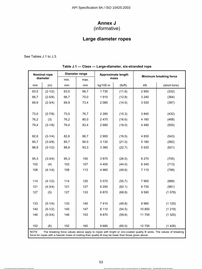
ISO 10425:2003(E)
© ISO 2003 — All rights reserved 53
Annex J (informative)
Large diameter ropes
See Tables J.1 to J.3.
Table J.1 — Class — Large-diameter, six-stranded rope
Diameter range Nominal rope diameter min. max.
Approximate length mass Minimum breaking force
mm (in) mm mm kg/100 m (lb/ft) kN (short tons)
63,5 (2-1/2) 63,5 66,7 1 730 (11.6) 2 950 (332)
66,7 (2-5/8) 66,7 70,0 1 910 (12.8) 3 240 (364)
69,9 (2-3/4) 69,9 73,4 2 080 (14.0) 3 530 (397)
73,0 (2-7/8) 73,0 76,7 2 280 (15.3) 3 840 (432)
76,2 (3) 76,2 80,0 2 470 (16.6) 4 160 (468)
79,4 (3-1/8) 79,4 83,4 2 680 (18.0) 4 490 (505)
82,6 (3-1/4) 82,6 86,7 2 900 (19.5) 4 830 (543)
85,7 (3-3/8) 85,7 90.0 3 130 (21.0) 5 180 (582)
88,9 (3-1/2) 88,9 93,3 3 380 (22.7) 5 520 (621)
95,3 (3-3/4) 95,3 100 3 870 (26.0) 6 270 (705)
102 (4) 102 107 4 400 (44.0) 6 340 (713)
108 (4-1/4) 108 113 4 960 (49.6) 7 110 (799)
114 (4-1/2) 114 120 5 570 (55.7) 7 900 (888)
121 (4-3/4) 121 127 6 200 (62.1) 8 730 (981)
127 (5) 127 133 6 870 (68.8) 9 590 (1 078)
133 (5-1/4) 133 140 7 410 (49.8) 9 960 (1 120)
140 (5-1/2) 140 147 8 110 (54.5) 10 800 (1 219)
146 (5-3/4) 146 153 8 870 (59.6) 11 700 (1 320)
152 (6) 152 160 9 680 (65.0) 12 700 (1 426)
NOTE The breaking force values above apply to ropes with bright or zinc-coated quality B wires. The values of breaking force for ropes with a heavier mass of coating than quality B may be lower than those given above.
API Specification 9A / ISO 10425:2003
53
Copyright American Petroleum Institute Reproduced by IHS under license with API
Document provided by IHS Licensee=HOCOL S A/9984411001, 03/29/2005 09:56:34 MSTQuestions or comments about this message: please call the Document Policy Groupat 303-397-2295.
--`,,`,,```,`,`,,`,,`,``,,`,,``-`-`,,`,,`,`,,`---

ISO 10425:2003(E)
54 © ISO 2003 — All rights reserved
Table J.2 — Class — Large diameter spiral strand
Diameter range Nominal rope diameter
min. max. Approximate length
mass Minimum breaking
force
mm (in) mm mm kg/100 m (lb/ft) kN (short tons)
102 (4) 102 107 5 500 (37.0) 8 830 (993)
108 (4-1/4) 108 113 5 700 (38.3) 9 810 (1 100)
114 (4-1/2) 114 120 6 600 (44.4) 11 000 (1 240)
121 (4-3/4) 121 127 7 300 (49.1) 12 300 (1 380)
127 (5) 127 133 8 200 (55.1) 13 500 (1 520)
133 (5-1/4) 133 140 8 800 (59.1) 14 700 (1 650)
140 (5-1/2) 140 147 9 600 (64.5) 16 700 (1 880)
146 (5-3/4) 146 153 10 900 (73.2) 17 900 (2 010)
152 (6) 152 160 11 600 (78.0) 19 700 (2 210)
Table J.3 — Class — Large diameter full-locked coil
Diameter range Nominal rope diameter
min. max. Approximate length
mass Minimum breaking
force
mm (in) mm mm kg/100 m (lb/ft) kN (short tons)
76,2 (3) 76,2 80,0 3 300 (22.2) 5 450 (613)
82,6 (3-1/4) 82,6 86,7 3 900 (26.2) 6 480 (728)
88,9 (3-1/2) 88,9 93,3 4 500 (30.2) 7 450 (837)
95,3 (3-3/4) 95,3 100 5 150 (34.6) 8 540 (960)
102 (4) 102 107 5 950 (40.0) 9 850 (1 110)
108 (4-1/4) 108 113 6 600 (44.4) 10 100 (1 140)
114 (4-1/2) 114 120 7 300 (49.1) 12 200 (1 370)
121 (4-3/4) 121 127 8 250 (55.4) 13 800 (1 550)
127 (5) 127 133 9 100 (61.2) 15 100 (1 700)
140 (5-1/2) 140 147 10 900 (73.3) 18 300 (2 060)
API Specification 9A / ISO 10425:2003
54
Copyright American Petroleum Institute Reproduced by IHS under license with API
Document provided by IHS Licensee=HOCOL S A/9984411001, 03/29/2005 09:56:34 MSTQuestions or comments about this message: please call the Document Policy Groupat 303-397-2295.
--`,,`,,```,`,`,,`,,`,``,,`,,``-`-`,,`,,`,`,,`---

ISO 10425:2003(E)
© ISO 2003 — All rights reserved 55
Annex K (informative)
Information with enquiry or order
The following information should be provided by the purchaser when making an enquiry or placing an order:
a) reference to this International Standard;
b) quantity and length;
c) nominal diameter;
d) rope class or construction;
e) core type;
f) rope grade;
g) wire finish;
h) lay direction and type;
i) preformation;
j) lubrication;
k) any particular marking requirements;
l) any particular packing requirements;
m) minimum breaking force required.
API Specification 9A / ISO 10425:2003
55
Copyright American Petroleum Institute Reproduced by IHS under license with API
Document provided by IHS Licensee=HOCOL S A/9984411001, 03/29/2005 09:56:34 MSTQuestions or comments about this message: please call the Document Policy Groupat 303-397-2295.
--`,,`,,```,`,`,,`,,`,``,,`,,``-`-`,,`,,`,`,,`---

Annex L (Informative)
API Monogram
L.0 Introduction
The API Monogram Program allows an API Licensee to apply the API Monogram to products. Products stamped with the API Monogram provide observable evidence and a representation by the Licensee that, on the date indicated, they were produced in accordance with a verified quality management system and in accordance with an API product specification. The API Monogram Program delivers significant value to the international oil and gas industry by linking the verification of an organization's quality management system with the demonstrated ability to meet specific product specification requirements.
When used in conjunction with the requirements of the API License Agreement, API Specification Q1, including Annex A, defines the requirements for those organizations who wish to voluntarily obtain an API License to provide API monogrammed products in accordance with an API product specification.
API Monogram Program Licenses are issued only after an on-site audit has verified that the Licensee conforms to both the requirements described in API Specification Q1 in total, and the requirements of an API product specification.
For information on becoming an API Monogram Licensee, please contact API, Quality Programs, 1220 L Street, N. W., Washington, DC 20005 or call 202-682-8000 or by email at [email protected].
L.1 API Monogram Marking Requirements
These marking requirements apply only to those API licensees wishing to mark their products with the API Monogram.
Application of the API Monogram shall be per the manufacturers API Monogram Marking Procedure as required by API Specification Q1.
L.1.1 Additional Requirements
In addition to the requirements in of this standard, the marking shall also include: API Spec 9A.
API Specification 9A / ISO 10425:2003
56Copyright American Petroleum Institute Reproduced by IHS under license with API
Document provided by IHS Licensee=HOCOL S A/9984411001, 03/29/2005 09:56:34 MSTQuestions or comments about this message: please call the Document Policy Groupat 303-397-2295.
--`,,`,,```,`,`,,`,,`,``,,`,,``-`-`,,`,,`,`,,`---

ISO 10425:2003(E)
56 © ISO 2003 — All rights reserved
Bibliography
[1] ISO 9001, Quality management systems — Requirements
API Specification 9A / ISO 10425:2003
56
API Specification 9A / ISO 10425:2003
57
Copyright American Petroleum Institute Reproduced by IHS under license with API
Document provided by IHS Licensee=HOCOL S A/9984411001, 03/29/2005 09:56:34 MSTQuestions or comments about this message: please call the Document Policy Groupat 303-397-2295.
--`,,`,,```,`,`,,`,,`,``,,`,,``-`-`,,`,,`,`,,`---
Additional copies are available through Global Engineering Documents at (800) 854-7179 or (303) 397-7956
Information about API Publications, Programs and Services is available on the World Wide Web at http://www.api.org
Product No: GX9A25
Copyright American Petroleum Institute Reproduced by IHS under license with API
Document provided by IHS Licensee=HOCOL S A/9984411001, 03/29/2005 09:56:34 MSTQuestions or comments about this message: please call the Document Policy Groupat 303-397-2295.
--`,,`,,```,`,`,,`,,`,``,,`,,``-`-`,,`,,`,`,,`---