SPECIFICATION FOR MANUFACTURE OF HEAT · PDF file2.1 Economizer heat exchanger ......
39
ANNEXURE TO TENDER NO. DPS/MRPU/IGCAR/FAB/2092/PT-2294 1. Description of the item : Manufacture and supply of heat exchangers for sodium system 2. Detailed SPECIFICATIONS: SPECIFICATION FOR MANUFACTURE OF HEAT EXCHANGERS FOR SODIUM SYSTEM SECTIONS Page No. 1. GENERAL SPECIFICATION FOR MANUFACTURING OF HEAT EXCHANGERS FOR SODIUM SYSTEM 1 2. SEPARATE SPECIFICATION RELATED TO EACH EQUIPMENT 2.1 Economizer heat exchanger (EHX) 13 2.2 Sodium to air heat exchanger (AHX) 25 2.3 Economizer for Cold trap (CTEHX) 30
Transcript of SPECIFICATION FOR MANUFACTURE OF HEAT · PDF file2.1 Economizer heat exchanger ......

ANNEXURE TO TENDER NO. DPS/MRPU/IGCAR/FAB/2092/PT-2294 1. Description of the item : Manufacture and supply of heat exchangers for sodium system 2. Detailed SPECIFICATIONS:
SPECIFICATION FOR MANUFACTURE OF
HEAT EXCHANGERS FOR SODIUM SYSTEM
SECTIONS Page No.
1. GENERAL SPECIFICATION FOR MANUFACTURING OF HEAT EXCHANGERS FOR SODIUM SYSTEM
1
2. SEPARATE SPECIFICATION RELATED TO EACH EQUIPMENT
2.1 Economizer heat exchanger (EHX) 13
2.2 Sodium to air heat exchanger (AHX) 25
2.3 Economizer for Cold trap (CTEHX) 30

Page 1 of 38
SECTION 1
SPECIFICATION FOR MANUFACTURE OF HEAT EXCHANGERS FOR SODIUM SYSTEM
GENERAL SPECIFICATION

Page 2 of 38
MANUFACTURING OF HEAT EXCHANGERS FOR SODIUM SYSTEM
GENERAL SPECIFICATION 1. INTRODUCTION
The components listed in Table 1 are to be fabricated for Sodium Technology Complex (STC) as per the various clauses of this specification and the drawing enclosed with this specification. The material in all the forms like plates, rounds, pipes, tubes with SS 316LN confirming to ASTM specification and ER 16-8-2 welding rods required for welding will be supplied to the manufacturer as free issue material. All other materials are in the scope of the manufacturer. After completion of the fabrication and testing the components are required to be delivered at Kalpakkam. This document covers the detailed specifications for fabrication of the equipment, its inspection, testing and transportation from the manufacturers shop to IGCAR. Subcontracting of the entire manufacturing activities of equipment is not permitted. Subcontracting any specific work shall be with the prior approval from the purchaser. Separate specifications related to each equipment are covered in Section 2.
Table.1: List of equipment and specification subsection
SNo Name of the equipment Qty Subsection 1 Economiser heat exchanger (EHX) 1 Section 2.1 2 Sodium to air heat exchanger (AHX) 1 Section 2.2 3 Economiser for Cold trap (CTEHX) 1 Section 2.3
2. SCOPE
a. Study of design drawing, preparation of detailed fabrication drawing and assembly procedure, quality assurance plan (QAP), Operation process sheets and stage wise inspection plan.
b. Preparation of different manufacturing procedures and qualification of manufacturing process.
c. Preparing the material requirement with cutting plan for manufacturing the components. d. Collection of free issue material from IGCAR stores with proper insurance and its
transportation after the approval of cutting plan by IGCAR. e. Fabrication of components as per approved fabrication drawings and QAP. f. Inspection and testing g. Chemical cleaning including degreasing, pickling and passivation are to be carried out
before and after fabrication of all the components. h. Design, procurement of materials and manufacture of jigs and fixtures and tooling
required for the manufacture, handling and inspection at shop. i. Design, procurement of materials, manufacture and supply of handling and transportation
structure. j. Transportation and delivery at site with guarantee of the components. Delivery to Stores
within 12 months from the date of acceptance of all the free issue materials.
k. Material accounting of free issue material.

Page 3 of 38
3. APPLICABLE SPEFICATION AND DRAWINGS
The latest editions of the following ASME Section II Part A&C : Materials, welding rod and filler rod specifications. ASME Section VIII Div1 : Code for unfired pressure vessel. ASME Section IX : Specifications for welding procedure and performance
qualification. ASME Section V : Procedure for Non-destructive examinations. ASTM A 240 : Standard Specification for Chromium and Chromium-
Nickel Stainless Steel Plate, Sheet, and Strip for Pressure Vessels and for General Applications.
ASTM E- 165 : Method for liquid penetrant inspection. ASTM E-94 : Recommended practice for radiography testing. ASTM A-380 : Standard Practice for Cleaning, Descaling, and Passivation
of Stainless Steel Parts, Equipment, and Systems. ASTM A 312 : Specification for Seamless, Welded, and heavily cold
worked austenitic Stainless Steel Pipes. ASTM A 213 : Specification for Seamless Ferritic and Austenitic Alloy
Steels for Boiler, Super heater, and Heat-Exchanger Tubes.
ASTM A 276 : Specification for Stainless Steel Bars and Shapes. ASTM A 577 : Standard Specification for Ultrasonic Angle-Beam
Examination of Steel Plates. ASTM A 578 : Standard Specification for Straight-Beam Ultrasonic
Examination of Rolled Steel Plates for Special Applications
ASTM A 262 : Standard Practices for Detecting Susceptibility to Intergranular Attack in Austenitic Stainless Steels
IS 2102: Part 1 : 1993/ISO 2768-1 : 1989
: General tolerances Part 1 Tolerances for linear and angular dimensions without individual tolerance indications.
IS 2102: Part 2 : 1993/ISO 2768-2 : 1989
General tolerances Part 2 Geometrical tolerances for features without individual tolerance indications
The following drawings shall be considered as reference drawings to prepare the fabrication drawings of components. 1 IGC/FRTG/99300/DD/4004- RA (1 Sheet) for Economiser heat exchanger (EHX) 2 IGC/FRTG/99300/DD/4013- RA (4 Sheets) for Sodium to air heat exchanger (AHX) 3 IGC/FRTG/99300/DD/4012- RA (1 Sheet) for Economiser for Cold trap (CTEHX) 4 IGC/FRTG/99300/DD/4020/R-A (1 Sheet) for forging of EHX and CTEHX tube sheets
4. PREPARATION OF MANUFACTURING DRAWINGS & DOCUMENTS
The manufacturer shall prepare detailed shop drawings/sketches based on design drawings indicating all the dimensions with tolerances for all individual items, subassemblies, final assemblies etc. Tighter tolerances shall be apportioned at various intermediate stages of manufacture in order to achieve the final requirements specified in the purchaser’s drawings. The drawings prepared by the manufacturer shall conform to the latest relevant ISO/ Indian Standards with complete dimensions and tolerances for the item / part. The shop drawings

Page 4 of 38
shall also include all the welds and their details, including method of inspection / examination, surface finish, bill of materials, allowances for cutting and machining etc., besides other relevant information and details. The drawings prepared by the manufacturer shall be approved by the purchaser prior to start of manufacturing activities. In case of conflict between applicable documents, the technical requirements mentioned in this specification shall govern. (In case of any dispute the purchaser’s decision shall be final and binding). The purchaser reserves the right to make minor dimensional changes before confirming the drawings for manufacture. Such changes shall be within the scope of the specified work and shall not be considered as extra.
Based on the approved drawings, manufacturer shall prepare detailed operation process sheets (OPS) which includes sketches for the individual parts/subassemblies/assembly, inspection requirements, inspection agency, reference documents, photography etc., for the individual components, subassemblies and final assembly. The same shall be got approved from the purchaser before start of actual manufacture. The manufacturer shall strictly follow the approved OPS. Jigs and fixtures and tooling required for the manufacture, assembly, inspection and testing of the different components shall be designed by the manufacturer and drawings for above shall be prepared by the manufacturer.
Based on the approved manufacturing drawing and operation process sheets, material cutting plan for SS 316LN material shall be prepared and the same may be submitted to the purchaser for approval. The required material in different forms with 316LN chemical composition will be issued to the manufacturer based on the approved cutting plan only.
The details provided in the drawings listed in this specification are comprehensive and provide necessary information for the manufacturer for the preparation of any shop/manufacturing drawings. The manufacturer shall scrutinize the drawings and bring out missing information/discrepancy/mismatch, etc, if any, to the notice of the purchaser in writing at the time of submission of technical part of the tender. If not done so by any successful bidder, then the bidder shall be fully responsible for any difficulties/problems faced during the manufacture, assembly and testing of the component and shall bear the cost of any repair/rework carried out to solve the problems. All the manufacturing and quality assurance documents such as manufacturing process sheets, material cutting plan, quality assurance plan, manufacturing procedure, welding procedures, weld data sheets, assembly procedure, packing procedure, inspection and testing procedure etc. shall be prepared by the manufacturer and submitted to the purchaser for approval before taking up the manufacture. These documents shall be submitted to the purchaser in digital form in a permanent storage device.
5. MATERIALS, MANUFACTURE AND WELDING REQUIREMENTS
5.1 Materials
All the forms of materials with SS 316LN material composition such as plates conforming to ASTM A240 Type 316 LN, rounds conforming to ASTM A 276 Type 316LN, pipes conforming to ASTM A 312 Type TP 316LN, tubes confirming to ASTM A 213 Type TP 316LN and forgings of tube sheets required for fabrication and assembly of economizer heat exchanger (EHX) and economizer heat exchanger (CTEHX) will be supplied as free issue material to the manufacturer. All materials other than SS 316LN chemistry in different forms indicated in the design drawings are in the scope of manufacturer. The material of construction indicated as SS 316LN / 316L in drawing shall be treated as SS 316L and the same is in the scope of manufacturer. The manufacturer shall collect the free issue material as per the approved cutting plan from IGCAR stores. After completion of the manufacturing

Page 5 of 38
process, the manufacturer shall prepare a material utilization report and submit to the purchaser for approval. For welding between SS 316LN to SS 316LN or SS 316LN to SS 316L by TIG welding process, ER 16-8-2filler wires shall be used. The filler wires for welding between SS 316L to SS 316L by TIG welding process shall be ER 316L confirming SFA 5.9 of ASME section II part C. The required ER 16-8-2 filler wires will be supplied as free issue material. The required SS 316L filler wires shall be in the scope of the manufacturer. An estimation of the required 16-8-2 filler wire shall be prepared by the manufacturer and submit to the purchaser for approval. The manufacturer shall collect the 16-8-2 grade filler wire as free issue material as per the approved estimate from IGCAR stores. After completing the manufacturing process, as in the case of other free issue materials, a material utilization certificate is required for this case also. Collection of the free issue material from IGCAR stores with proper insurance and transporting the same to the manufacturer's shop for fabrication are in the scope of manufacturer. After manufacturing the components utilization certificate of the individual free issue material has to be submitted to IGCAR by the manufacturer. Any balance of free issue material has to be returned to IGCAR stores at the expense of manufacturer. The shipping release of the equipment will be issued only after production of approved material utilization report.
Manufacturer shall ensure the quality of material which is in the scope of manufacturer and purchased by the manufacturer. Relevant test reports like chemical composition, mechanical tests, heat treatment, ultrasonic examinations etc. shall be provided. All materials shall be identified and certified by the purchaser before taking to fabrication. Each piece of material shall have distinguishable identification and that identification shall be co-relatable to the manufacturer’s Test Certificate (MTC). IGCAR inspector will collect material sample to conduct the material test in IGCAR laboratory for verifying the material test certificate supplied by the material manufacturer. All plates shall be subjected to Ultrasonic Testing by Angle Beam or Normal Beam technique in accordance with ASTM A 577 & A 578 respectively. All the pipes utilized for fabrication shall be inspected by ultrasonic examinations using angle beam as well as normal beam techniques. The examination shall be applied using both axial and circumferential Vee notches to 100% coverage of the surface area. The depth of defect standard (on ID as well as on OD) shall not exceed 5% of nominal wall thickness or 0.1 mm whichever is large. All materials for fabrication work shall conform to the specifications issued by Purchaser. No substitution of equivalent material is permissible unless specifically authorized by the purchaser through a ‘Design Change Request’ (DCR).
5.2 Manufacture
Any activity planning to be given as sub-contract to third party to be indicated clearly in the QAP and same should be approved by IGCAR prior to manufacturing activity.
5.2.1 Material Handling and Assembly
The material has to be chemically cleaned before the assembly if it is not properly cleaned before. The cutting, bending, rolling and welding operations and assembly of components shall be carried out inside a dust free hall. The cutting plan of all material shall be prepared properly to minimize the wastage of the material. The forming tolerances on cylindrical shells, dished ends and pipe bends shall be as indicated in the drawings. All material shall be cut preferably by mechanical cutting process wherever possible. Any unavoidable thermal cutting shall only be done by plasma cutting process with adequate edge
Page 6 of 38
allowance for removal by grinding or machining. After cutting, the edges shall be ground clear of the heat affected zone and edges shall be examined by LPE. Only aluminum oxide grinding wheels shall be used for grinding process. During fabrication, the prepared edges of plates, pipes and other fittings shall be examined by LPE method to detect defects such as lamination, cracks etc. All defects shall be removed / repaired as per procedure approved by the Purchaser and shall be inspected by the Purchaser. As far as possible, mechanical clamping (without welding) shall be used for making fit ups. Temporary fittings such as tacking strips, cleats etc. shall be carefully removed to prevent damage to the parent plate. Fit up brackets shall be used only on the vessel outside. Any blemishes on the parent material shall be rectified and the area tested/ examined by liquid penetrant method for detection of cracks or any other defects, and if required, radiography shall be carried out as per applicable codes. Sufficient lifting arrangement shall be provided in the tanks to handle the tanks in horizontal and vertical positions. Spreader shall be used while handling the tanks in vertical positions. The manufacturer shall submit the welding layout plan to purchaser for approval of welding layout plan before initiation of fabrication of tanks. 5.2.2 Forming of shell and dished end
The shells and dished ends shall be made by cold forming process. Tolerances for forming of shells and dished ends shall be as per Part 4.3 of ASME Section VIII Division 2. The following tests shall be conducted after forming.
- Dimensional checks - Visual examination - LPE of the entire surface
If the shells or dished ends are subjected to heat treatment, these tests shall be after the heat treatment.
5.2.3 Bending of Pipes
The pipes shall be cold/hot bent. If pipes are hot bent, the pipes shall be pickled and passivated. Sample bends shall be inspected for non-sensitized structure. The active surface of the bending machine shall be free from roughness, dents, and pits in order to avoid any mark, scratches causing on the job during forming process. The location of the bend in the pipe shall be as per details provided in drawing. The following tests shall be conducted after pipe bending. a. Visual examination. b. Dimensional and layout check for profile. c. LPE on formed surfaces
The acceptance criteria shall be as follows:
a. Visual examination shall show good workmanship and bends shall be free of cracks. b. ‘No indication’ shall be the acceptance standard for LPE. c. Ovality shall be 8% maximum as defined in PFI Standard ES-24 and shall be measured at
middle of the bend. d. Buckles shall meet PFI Standard ES-24.
e. Thinning allowance for bend radius of 2D, 3D, 4D and 5D and above shall be maximum of 18%, 10%, 9% and 6% respectively.

Page 7 of 38
5.3 Heat Treatment
Formed parts such as dished ends, shell and pipe bend shall be heat treated irrespective of forming method. Solution annealing heat treatment shall be carried out at 1065 ±15°C by holding for 2.5 minutes / mm of thickness with minimum of 30 minutes and cooling in still air. Rate of heating shall be maximum of 150°C/h and jobs can be loaded in the furnace at a maximum temperature of 400°C. Furnace to be used shall be qualified. Test coupons of indicated material shall be loaded in the furnace and checked for intergranular attack as per ASTM A 262- practice E. The solution annealing shall be carried out in an electrical furnace. If electrical furnace is not used, other type of furnace may be used provided that the furnace atmosphere for solution annealing shall not have more than 2% oxygen to avoid scaling and sulphur content shall not exceed 3 gm/m3.
5.4 Welding
All the welding shall be performed only by TIG process. During welding, care shall be taken to minimize distortion and shrinkage and to obtain final tolerances within limits allowed by ASME Section VIII Division I unless otherwise mentioned and applicable drawings. Proper welding sequence and balanced techniques shall be adopted to minimize weld distortion. The filler wires for welding between SS 316LN to SS 316LN or SS 316LN to SS 316Lby TIG welding process shall be ER 16-8-2. The filler wires for welding between SS 316L to SS 316L by TIG welding process shall be ER 316L confirming SFA 5.9 of ASME section II part C. No cold forming shall be carried out on any weld in the shell and dished end. Inter pass temperature during welding of austenitic SS shall not exceed 125 ºC. Not more than one repair is allowed at any location. For any additional repairs, a repair procedure has to be prepared by manufacturer and qualified by purchaser.
5.4.1 Welding qualifications
Qualified welder shall carry out the welding of components. Applicable standard shall be ASME Sec. IX. X ray radiography shall be the basis for performance qualification. The manufacturer shall submit a detailed weld data sheet indicating the welding parameters, permissible extent of each weld defects, inspection stages prior to, during and after welding for approval of purchaser. On receipt of approval by the purchaser, welding procedure and performance qualifications shall be carried out and submitted to purchaser. The same procedure and qualified welders shall be employed while fabricating the components covered by this tender. Manufacturer shall make the necessary arrangement for welding qualification and testing of weld specimen with relevant reports. 5.4.2 Production test coupons
One test coupon per 20 m of weld length shall be made for each type of weld and for each thickness. The width of each plate of test coupon shall be 125mm and length shall not be less than 300mm. The test coupon shall have the same welding parameters as the production weld. These test coupons shall be subjected to all the tests by the manufacturer as called for in the welding Procedure Qualification test. In the case of a test coupon failure to meet the requirements of the specifications, the test results together with the results of non – destructive examination carried on the part shall be submitted to the purchaser at the earliest. The final decision shall be, however, at the discretion of the Purchaser.

Page 8 of 38
6 INSPECTION, EXAMINATION, TESTING AND REPORTS
Quality assurance and stage wise inspection plan (QAP) shall be prepared by manufacturer and approved by purchaser. The QAP shall govern the inspection, examination and testing. In case of any discrepancy between QAP and specification, the specification shall govern. ASME section–V requirements shall be followed for inspection and testing of all components. NDE personnel employed for examination shall be qualified/certified by either ISNT or an authorized agency in accordance with IS 13805/ISNT-TC-1A of ASNT. Level I/II NDE personnel shall be employed for execution of examination and Level II/III personnel shall evaluate the indications. The manufacturer’s factory/workshop shall be accessible for the purchaser’s representative for stage inspection as and when required. All the tests, necessary arrangements for inspection and testing shall be within the scope of the manufacturer.
6.1 General
Manufacturer shall prepare inspection procedures for dimensional inspection, LPE, radiography, ultrasonic, helium leak testing and any other inspection and testing called for in the tender and shall submit the same for Purchaser’s approval. These inspections shall be carried out as per approved procedure.
The manufacturer shall provide for the inspection and testing services and facilities for all the manufacturing works. The manufacturer shall maintain records of all inspection and tests and these shall be made freely available to the purchaser’s authorized representative. The manufacturer shall digitize the radiographic images of all radiographed welds and supply the images in electronic media to the purchaser. All welds shall be ground smooth and shall meet the weld fit up and other tolerances as defined in the drawings. Wherever weld fit up tolerances are not given, the manufacturer shall prepare the same and get it approved from Purchaser before welding.
6.2 Material identification
All the material including free issue materials from the purchaser shall be identified, correlated with the linkable test certificates and stamped properly by IGCAR inspector. IGCAR inspector will collect material samples for auditing of chemical and mechanical test reports wherever it demands. The sampling criterion for the test coupons for auditing is the discretion of the inspector. The testing of the audit test coupons will be performed by IGCAR.
6.3 Dimensional inspection
Dimensional check for the individual components and the completed tanks shall be carried out as per the approved procedures and shall meet the requirements of dimensions & tolerances specified in the drawings.
6.4 Visual examination
• Each & every part individually, subassembly of parts and final assembly shall be 100% visually examined to check the soundness of the part. The part shall be free from scratches, dents, tears or any other injurious defects particularly affecting the thickness of the part.
• The entire formed surfaces shall be 100% visually examined to check the soundness of the part and shall be free from scratches, dents, tears or any other injurious defects particularly affecting the thickness of the part.
• All welds shall be examined visually after each pass and all notable indications shall be recorded.

Page 9 of 38
6.5 Liquid penetrate examination (LPE)
Inspection shall be carried out as per ASTM-E-165 and ASME section-V Article-6. ASME Section VIII Division I shall be followed for acceptance criteria. All necessary arrangements for carrying out LPE and its processing are fully in the scope of the manufacturer. 6.5.1 Examination of Formed Parts LPE of entire formed surfaces such as dished ends and shell nozzle pullouts shall be carried out. If heat treatment is required, LPE shall be carried out after heat treatment. 6.5.2 Examination of Butt Welds LPE of weld edge preparation, root pass, back gouge and final pass of weld shall be carried out. For welds coming on the tank which cannot be radiographed or ultrasonically tested, LPE shall be done after each pass.
6.5.3 Examination of Groove Fillet Welds LPE shall be carried out in the root pass and final pass of all groove fillet welds. If groove fillet weld could not be radiographed or ultrasonic tested, LPE shall be carried out after each pass. 6.5.4 Examination of Fillet Welds Liquid penetrant examination shall be carried out on the root and final pass of all the welds.
6.6 Radiographic examination (RE)
Radiographic examinations by X -Ray radiography shall be carried out for all but welds and possible groove and fillet welds. Radiography of the repaired weld shall be with distinct identification marks. X -Ray radiography shall be according to ASME Section V Article-2 and ASTM-E-94. All necessary arrangements for carrying out radiography and its processing are fully in the scope of the manufacturer. The acceptance criteria for radiography shall be as per ASME Section VIII Division I.
6.7 Ultrasonic examination
Ultrasonic examination shall be done as per ASME section-V Article-4 for welds where radiography is not possible. The groove fillet weld shall be 100% ultrasonic examination and LPE shall be carried out after each pass if radiographic examinations are not viable. All necessary arrangements for carrying out Ultrasonic examination and its processing are fully in the scope of the manufacturer .Ultrasonic examination shall be performed in the presence of IGCAR representative. The acceptance criteria for ultrasonic examinations shall be as per ASME Section VIII Division I.
6.8 Pneumatic pressure test
The sodium components shall be subjected to pneumatic pressure test with the test pressure as given in the Table 2 using air confirming ISO8573.1 Class 1.4.1 for minimum of 10 minutes as per ASME Section VIII Division I UG 100.
Table 2: Pneumatic test pressure for pressure hold test of the components
SNo Name of the equipment Test pressure MPa
1 Economiser heat exchanger (EHX) 3.0
2 Sodium side of sodium to air heat exchanger (AHX) 3.0
3 Economiser for Cold trap (CTEHX) 1.65

Page 10 of 38
6.9 Pneumatic leak test
A pneumatic leak test with dry air confirming ISO8573.1 Class 1-4-1 under 0.1 MPa (g) shall be carried out as a pretest to helium leak test during which the welds will be tested by soap bubble test. The pneumatic leak test shall be conducted after the pneumatic pressure test. It shall be continuous for a period of 24 hrs for observing any pressure drop in the tanks. No leak is acceptable.
6.10 Helium leak test
Helium leak test (HLT) under vacuum shall be conducted as per ASME Section V Article-10 Appendix - V. Global leak rate shall not exceed 10-7 Pa-m3/s and local leak shall not exceed 10-8 Pa-m3/s. Any leak rate greater than acceptance limit shall be repaired by proper procedure. Leak testing equipment shall be calibrated before carrying out leak test. Any failure during test condition shall be repaired by the manufacturer with purchaser permission. After executing repairs, all tests as defined earlier shall be carried out under the same conditions. All the tests shall be within the scope of the manufacturer.
6.11 Surface treatment
All the austenitic stainless steel parts shall be cleaned, degreased, pickled and passivated as per annexure I. The equipment and chemical items required for the chemical cleaning is in the scope of the manufacturer.
6.12 Test failure
In the event of any failure of the tanks or its parts to meet an inspection or test requirements specified, the manufacturer shall notify the Purchaser or his authorized representative. The manufacturer shall obtain permission from the Purchaser before any repair is undertaken. All repaired welds shall be re-examined and tested as per the requirements of the original weld and shall meet the requirements of the same. The number of repairs permitted for weld is limited to maximum two times at any location.
6.13 Reports
Deviation from the approved drawing, if any, shall be brought to the notice of the purchaser and approval shall be obtained. The manufacturer shall submit a detailed quality assurance plan along with the manufacturing drawing for purchaser approval. After completion of manufacture, inspection and testing, the manufacturer shall submit three copies of the following documents in book form along with as-built drawings.
• All shop drawings along with a soft copy in AutoCAD format. • All procedures of manufacture and inspection along with a soft copy.
• All qualification, inspection and test reports in digital form. • Copies all photos taken during different stages of manufacturing with a soft copy.
The manufacturer shall submit the documents within a period of one months from the date of issue of shipping release. Radiographic films shall be supplied to the purchaser in electronic media by digitizing radiographic images along with the component details. Digital copies shall be submitted in a permanent storage device like external hard disc. A separate drawing indicating the radiographic image identification tag shall be prepared and attached with the images.

Page 11 of 38
The above documents shall be duly signed by both the authorized representatives of the manufacturer and purchaser as mutually agreed upon. All the documents (other than drawings) shall be submitted in bound volumes.
6.14 Final acceptance criteria
The final acceptance criteria of all the components shall be based on all testing and its acceptance criteria as mentioned in the subsections of this section (Section 6).
7 PACKING AND TRANSPORTATION
After the acceptance tests, the components shall be put under vacuum and then filled with commercially available dry nitrogen (IS:1747-1972) for the transport and storage. The openings shall be carefully and firmly blocked to ensure leak tightness before dispatch.
On completion of fabrication the manufacturer shall deliver the fabricated components at IGCAR, Kalpakam, Tamilnadu. Packing shall withstand any sort of shocks during handling, transportation and storing at site. Packing procedure shall be prepared by the manufacturer and submitted to the purchaser for approval. The packing shall be carried out as per approved procedure. All overhanging parts (nozzles, headers, etc.) shall be suitably stiffened by welding supports etc. to prevent damage due to vibration. No movement of any parts is permitted during transportation. Transportation of fabricated components from the manufacturer’s shop to IGCAR, Kalpakkam site shall be carried out by the manufacturer as per approved procedure. All the surfaces shall be covered with minimum two layers of polythene sheet (0.1 mm thick) throughout the length. Polythene sheet shall be fixed suitably to the components. Sufficient quantities of hygroscopic materials shall be kept inside the box. The hygroscopic material shall not touch the component surface.
The component shall be packed and held rigidly inside a steel structure (dismountable type) with adequate support points to be designed by the supplier and approved by the purchaser. This steel structure shall be capable of taking the full load of component assembly in horizontal and vertical condition and during changeover from horizontal to vertical condition. Sufficient number of lifting hooks shall be designed and provided by the supplier as approved by the purchaser for lifting the structure when packed with the component, in horizontal condition as well as while making it vertical, and while lifting it in vertical condition. The transportation structure is meant for repeated handling and transportation of each component.
Component shall be placed on wooden/steel saddles which shall be bolted on to steel bottom frame with straps etc. Suitable wooden wedges shall be provided at various places so that there is no gap between box, component and saddles. Each component shall be packed inside the structure and it shall be closed entirely in a wooden casing for its seaworthy transport.
8 ELIGIBILITY AND GENERAL CONDITIONS The manufacturer shall meet all following requirements and submit the proof documents. Otherwise their offers will not be considered for evaluation.
Ø Experience in fabrication of austenitic stainless steel components of similar designs like shell and tube heat exchangers and welded finned tube heat exchanger.
Ø Facility to manufacture pullout joints upto a size of 35mm. Ø Outsourcing of employees as qualified welders for TIG welding and Level-2 inspector for
required inspection and examinations will not be allowed.
Page 12 of 38
Ø Separate fully covered, dirt free clean area shall be available for manufacturing stainless components. Adequate space more than 200m2 shall be available for parallel manufacturing of multiple components.
Ø EOT crane shall be available in the manufacturing area with a capacity not less than 5 t. Ø Part offers will be treated as incomplete and not be considered for evaluation. Incomplete
offers will not be accepted. The cost evaluation will be performed on the basis of combined cost of all the equipments. The orders will be issued only for the full set of components given in Table 1.
Ø Subcontracting of the entire manufacturing activities of an equipment is not permitted. Subcontracting any specific work like high frequency resistance welding of fins in AHX tubes shall be with the prior approval from the purchaser. The list of activities which is likely to be subcontracted shall be clearly indicated in the technical offer.
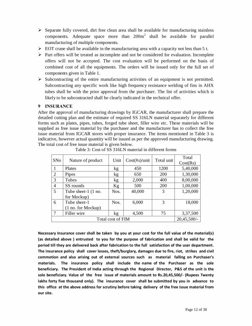
9 INSURANCE After the approval of manufacturing drawings by IGCAR, the manufacturer shall prepare the detailed cutting plan and the estimate of required SS 316LN material separately for different forms such as plates, pipes, tubes, forged tube sheet, filler wire etc. These materials will be supplied as free issue material by the purchaser and the manufacturer has to collect the free issue material from IGCAR stores with proper insurance. The items mentioned in Table 3 is indicative, however actual quantity will be issued as per the approved manufacturing drawing. The total cost of free issue material is given below.
Table 3: Cost of SS 316LN material in different forms
SNo Nature of product Unit Cost(Rs)/unit Total unit Total Cost(Rs)
1 Plates kg 450 1200 5,40,000 2 Pipes kg 650 200 1,30,000 3 Tubes kg 2,000 400 8,00,000 4 SS rounds Kg 500 200 1,00,000 5 Tube sheet-1 (1 no.
for Mockup) Nos. 40,000 3 1,20,000
6 Tube sheet-1 (1 no. for Mockup)
Nos. 6,000 3 18,000
7 Filler wire kg 4,500 75 3,37,500 Total cost of FIM 20,45,500/-
Necessary Insurance cover shall be taken by you at your cost for the full value of the material(s) (as detailed above ) entrusted to you for the purpose of fabrication and shall be valid for the period till they are delivered back after fabrication to the full satisfaction of the user department. The insurance policy shall cover losses, theft/burglary, damages due to fire, riot, strikes and civil commotion and also arising out of external sources such as material falling on Purchaser's materials. The insurance policy shall include the name of the Purchaser as the sole beneficiary. The President of India acting through the Regional Director, P&S of the unit is the sole beneficiary. Value of the free issue of materials amount to Rs.20,45,500/- (Rupees Twenty lakhs forty five thousand only). The insurance cover shall be submitted by you in advance to this office at the above address for scrutiny before taking delivery of the free issue material from our site.

Page 13 of 38
PROCESS LOSS The unaccountable permissible wastage during the manufacturing process should not exceed 20% of Free Issue Material.
10 GUARANTEE The manufacturer shall give a guarantee for the component against any defect in workmanship for a period of 12 months from the date of installation and for 18 months from the date of receiving the fabricated components at site whichever is earlier. If any deficiency is noticed in performance of the component because of manufacture, inspection & testing, the manufacturer upon notification by the purchaser and at purchaser’s convenience shall forthwith restore them to satisfactory condition without any extra cost to the purchaser. Manufacturer will not be responsible for the defect in the free issue material supplied by the purchaser.
Page 14 of 38
SUBSECTION 2.1
SPECIFICATION FOR MANUFACTURE OF ECONOMISER HEAT EXCHANGER

Page 15 of 38
SPECIFICATION FOR MANUFACTURE OF ECONOMISER HEAT EXCHANGER
1. INTRODUCTION Economizer Heat Exchanger (EHX) is a counter flow, shell and tube heat exchanger. The tubes are of 22mm OD x 1 mm wall thickness, rolled and welded to tube sheets. The tubes are arranged in a triangular pitch of 31 mm in each tube sheet. One end of each U shaped tube is welded to inner tube sheet and the other end is welded to outer tube sheet. The tube bundle is placed inside the shell of outer diameter of 336mm and thickness of 8mm. The hot sodium flows in the shell side of the EHX, whereas the cold sodium flows in the tube side of the EHX. 2. OPERATING CONDITIONS Thermal rating : 2.5 MW Shell side fluid : sodium Tube side : sodium Shell side Pressure : 1.1(MPa) (g) Tube Side Pressure : 1.1(MPa) (g) Max. Temperature : 600 °C 3. APPLICABLE DRAWINGS The applicable drawing for manufacture of economiser heat exchanger is IGC/FRTG/99300/DD/4004- RA (Sheet 1 of 1).
4. MANUFACTURE
4.1 Material Handling and Assembly As the tubes are generally received in passivated condition, they shall be taken up for manufacture only at appropriate time and need not be re-passivated unless found unacceptable or damaged during handling. The cutting of tubes, bending, rolling and welding of tubes to tube sheet and assembly of EHX shall be carried out inside a dust free hall. Each tube shall be inspected visually for any scratches, dents or any other defect resulting in loss of thickness before assembly into the tube bundle. Defective tubes shall be rejected. The forming tolerances on cylindrical shells, dished ends, and pipe bends shall be as indicated in the EHX drawings. Minimum length of axial and circumferential welding shall be performed for fabricating the shell of the EHX.
4.2 Drilling holes in tube sheet These shall be drilled as per the tolerances specified in the EHX drawings. TEMA
Class R Standard fit is the basis for arriving at drilling tolerances.
4.3 Instrumentation There is no instrumentation in the scope of manufactures for EHX.
4.4 Tube to Tube-Sheet weld Joint The tube-to-tube sheet joint shall be rolled and welded type, with welding carried out
by automatic / manual GTAW welding process without filler wire, after rolling. Rolling and welding procedure shall be qualified as per specifications given in Annexure 2.1A & 2.1B. Radiography is not required on this weld joint. However, fluorescent LPE shall be carried out. All the joints shall be acceptable to the purchaser.

Page 16 of 38
5. EXAMINATION, TESTING 5.1 Liquid Penetrate Examination (LPE)
Fluorescent LPE of the weld as per ASTM E-165 method-A type-3 (procedure A3) shall be carried out and no indication shall be permitted. Manufacturer shall prepare a procedure for carrying out inspection and get it approved by the purchaser.
5.2 Pneumatic Test The EHX tube side shall be subjected to a pneumatic test at 3.0 MPa for minimum
time of 30 minutes for pressure hold test.
5.3 Helium leak test Helium leak testing on tube side shall be performed before fabricating the shell of EHX. Shell side of the EHX shall be inspected by helium leak test after the complete assembly.

Page 17 of 38
ANNEXURE – 2.1A SPECIFICATION FOR PROCEDURE QUALIFICATION
FOR TUBE ROLLING OF EHX 1. SCOPE
This specification describes the requirements for the procedure qualification of rolling of the tubes in the tube sheet of EHX.
2. EQUIPMENT The rolling equipment used for full rolling and contact rolling shall be of mechanical tube expander roller type. The equipment is described as a set of torque control unit, connecting shaft and expander unit excluding the rolling unit [The mandrel, body or cage rollers are consumables]. Each equipment shall be identified by a serial number.
3. MATERIALS
3.1 Tube Sheet The material for the test block to be used for the qualification shall be of AISI 316LN or AISI 316 with a thickness same as that of production piece. The material heat number shall be identified. The standard size of the block shall contain 19 holes as per the layout of EHX tube sheet drawing.
3.2 Tubes The tubes used for the qualification test shall be of austenitic steel SS 316LN or SS 316. The heat/batch number of the tubes used for the qualification test shall be identified and recorded. The nominal size of tubes (diameter and thickness) shall be the same as that used in the production. The length of the tubes shall be as agreed upon with the purchaser.
4. PREPARATION OF BLOCK FOR QUALIFICATION TEST Holes shall be drilled to the same pattern, size, surface finish and tolerances as given in the drawings for production unit.
• The holes shall be free from longitudinal scratches. • The holes in the test block shall be numbered by hard punching. • The diameter of the holes in the test block shall be measured at three places along the
length of the hole and recorded. • The outside and inside diameter of the tubes shall be measured at minimum three locations
and shall be recorded for each tube and record shall be kept with suitable numbering system.
• Inside and outside surfaces of the tubes and whole surface shall be thoroughly cleaned and dried immediately prior to the insertion of tube for rolling.
5. TRIALS Adequate trials shall be conducted by the manufacturer to establish the rolling parameters and for operator training. The finalized parameters, which shall be used in the qualification test, shall be recorded in the format enclosed and submitted to purchaser’s representative prior to the qualification test.

Page 18 of 38
6. QUALIFICATION TEST The tube shall be placed into the hole such that the end of the tube shall be flush with the face of the block. The expansion shall be as per the enclosed sketch (Fig.1). Full expansion shall be carried out. This shall be carried out using the parameters established during trials. Suitable lubricants (free of halides) shall be used for rolling and shall be removed thoroughly after completion of rolling.
The mandrel and rollers shall be examined by the operator for signs of wear or damage prior to each rolling. Actual torque values for full expansion shall be recorded in the format given in Table-1A.
7. EVALUATION All the rolled tubes shall be visually examined for free from visible defects (viz.) scratches, dents, cracks and metal peal or any sharp transition.
• The inside diameter of all the rolled tubes shall be measured at 3 places and recorded. • The percentage thinning shall be calculated using the following formula.
Final ID after rolling in mm = (Hole diameter – Tube OD) in mm + Tube ID in mm +2 x Wall thickness of tube in mm x percentage thinning. (dimensions of original tube)
• The percentage thinning calculated as above shall be 7 to 10% for each rolled tube.
7.1 Visual Inspection Five out of ninteen tubes shall be longitudinally sectioned and inside surface shall be examined visually with an unaided eye for the smooth transition of the rolled region to the unrolled region and free from scratches, cracks, peels, etc.
All the five tube cross section showing the transition shall be photographed at 10x magnification for records. Typical longitudinal section shall be preserved for reference purpose and supplied along with the heat exchanger.
7.2 Hardness Test The tube sectioned for visual inspection can be used for hardness measurements.
Hardness measurement shall be carried out by Vickers hardness method under 1 kg load on cut section thickness.
In the same piece, flow of material inside the grooves shall also be checked and recorded for purchaser’s reference.
After rolling and welding of tubes to tube sheet as per approved procedure, tube shall be subjected to pull out test. The failure shall take place in the base tube. Pull out load shall be recorded.
8. RANGE OF QUALIFICATION The qualification shall be valid only for the length of rolling qualified. Any new set of
equipment or a change in the constituents of the equipment shall warrant a re-qualification prior to use.

Page 19 of 38
9. DOCUMENTATION AND APPROVAL The following documents shall be prepared and submitted to the purchaser:
i) Details of material heat number for test block and tubes. ii) Parameters used for qualification. iii) Report of dimensions and calculated values of % thinning. iv) Report for hardness test. v) Report for pull out test. vi) Photograph of the cross section of the rolled tube. The qualification test and evaluation shall be witnessed by Purchaser’s inspector or his
authorized representative and reports shall be submitted to the purchaser for approval. The test reports shall be included in the final list of documents submitted by the manufacturer.
TABLE – 1A
TUBE EXPANSION TEST RESULTS FOR EHX
Expander No. : Expander make: Block thickness: Material : Lubrication :
Legend
S Start M Middle E End OD Outside diameter ID Inside diameter T Thickness
Sl No
Hole No
Tube sheet hole diameter
Tube size
Torque ID after expansion
% Thinning Pull out strength in kg
Remarks
S M E S M E S M E S M E

Page 20 of 38
ANNEXURE – 2.1B SPECIFICATION FOR TUBE TO TUBE SHEET WELDING
OF EHX 1. SCOPE This specification gives the method and acceptance criteria for the qualification of the procedure of welding and the performance of the Welder/Welding operator for the tube to tube sheet welding of EHX. These tests shall be carried out in the presence of Purchaser’s Authorized Inspector.
2. APPLICABLE SPECIFICATION Annexure-2.1A Specification for procedure qualification for
tube rolling of EHX.
ASTM E 165 Specification for fluorescent solvent removal liquid penetrate examination
3. BASE METAL 3.1 Tube Sheet The base metal used for the procedure / performance qualification tests shall be of austenitic stainless steel AISI 316 LN or AISI 316.
3.2 Tubes The base metal shall be of austenitic stainless steel AISI 316 LN.
4. PROCESS The process used for tube to tube sheet welding shall be pulsed gas tungsten arc welding without addition of filler metal. The electrode shall be 2% thoriated tungsten electrode.
5. WELDING PROCEDURE
5.1 Sizing of the Test Block For procedure qualification test, tube sheet shall be of the same thickness as the production tube sheet. The tubes shall be of same nominal size as the production tubes and shall be from same heat batch.
5.2 Tube Holes A minimum of 19 holes shall be drilled for the procedure / performance qualification. The pitch of the holes shall be the same as the pitch of the holes in the tube sheet. The holes shall be drilled with the same procedure and to the same tolerances as used for production of tube sheet holes. The surface finish of the holes shall be the same as used for production holes. The tube shall be inserted into the hole and rolled in the test block with the same procedure as approved for the production rolling and welding. The cleaning procedure shall be identical with that of production job.
5.3 Joint Design and Cleanliness of Weldment The weld joint between the tube to the tube sheet shall be as shown in Fig.1. The welding shall be carried out in a single pass by pulsed GTAW without addition of filler metal. The welding

Page 21 of 38
shall be carried out after the tube rolling as per the approved procedure. The depth of penetration shall be equal to the thickness of the tube-minimum. Before welding, the joint shall be degreased by acetone and thoroughly cleaned by a lint free cloth to avoid porosity.
5.4 Shielding Gas High purity argon gas shall be used as the shielding gas during welding.
5.5 Electrical Supply Type : Direct Current Polarity : Electrode Negative
5.6 Welding
• The welding of tubes to tube sheet blocks shall be carried out in a dust free room.
• The welding parameters to be used for the qualification shall be established by adequate trials. After establishing the parameters, a procedure (WPS) shall be written which shall be approved by purchaser’s representative. Format for recording welding parameters shall be finalized in consultation with Purchaser’s representative.
• The machine setting shall be recorded at the beginning of the qualification welding and shall remain unaltered during the welding of blocks.
• The start and end of all welds shall be in the same position and shall be recorded.
5.7 Repairs The manufacturer shall also qualify the necessary procedure for repair that is envisaged during the welding of the EHX. The repair procedure shall be used on the EHX only after the approval of the purchaser.
6. NON-DESTRUCTIVE TEST 6.1 Visual Examination Ø The weld shall be subjected to a visual examination. The following are unacceptable.
• Any lack of fusion at the edge of the hole in the tube sheet. • Surface porosity, cavities, cracks, etc. • Tungsten inclusions.
Ø The weld surface shall be smooth and weld bead shall be uniform. Ø All the welds shall be examined for bore diameter using a plug gauge of diameter 20+0/-0.05
mm. All the welds of a procedure qualification / welder performance qualification shall pass the gauge inspection. Failure to pass the gauge inspection shall render the procedure / performance disqualified. Welds in the tube sheet which do not pass the gauge inspection shall be identified for further action.
Ø The weld shall be subjected to a liquid penetrant examination as per specification No. ASTM E-165 method A3. The following are unacceptable. • Any indication of whatsoever dimension, in the weld zone. • Any indication > 1.5 mm & indication < 1.5 mm if they are less than 3 mm apart, for
zone adjoining weld metal.

Page 22 of 38
7. DESTRUCTIVE EXAMINATION 7.1 Metallographic examination After non-destructive examination, five out of the nineteen tubes in the procedure qualification block shall be cut into two halves. The height of the weld bead and the form of the bead shall be verified and it shall meet the following requirements.
• The mean dimension of the throat shall not be less than 0.9 t and no individual throat dimension shall be less than 0.66 t (t= thickness of tube).
• Cracks shall not be permitted and porosity and inclusions are tolerated only if the local minimum leak path remains greater than 0.66t (t=thickness of the tube). However, the diameter of the single pore shall not exceed 0.2 mm [Refer Figures – 1A & 1B].
Macro-graphic examination shall be done at 20x magnification on the cut sections and it shall be verified that there are no cracks at the base of the weld bead. Three welds out of five for procedure qualification shall be examined as follows. The weld shall be ground off starting from the top and a microscopic examination shall be done (100x magnification) at every 0.2 mm till the base metal is reached. It shall be checked that any porosity or inclusion shall measure less than 0.2 mm, provided that this value is compatible with the dimensions ascertained from the transverse sections. Any suspected zone under macro-graphic examination shall be subjected to microscopic examination at sufficient magnification to identify the defect.
8. PERFORMANCE QUALIFICATION 8.1 Tests The requirements for the performance qualification test for welders and welding operators shall be the same as for the procedure qualification. Any welder or welding operator who carries out a procedure test that passes satisfactorily is thereby qualified.
8.2 Re-tests A welder who fails to meet the requirement of this specification shall be retested under the following conditions.
• When an immediate retest is made, the welder shall make twice the number of normally required test pieces and all of them shall pass the test requirements.
• When the welder had further training or practice, a complete retest of the performance shall be made.
9. RECORDING OF RESULTS The manufacturer shall maintain a register of the welders, which shall contain the following information and updated regularly.
• Welder’s name and identification mark. • Date of qualification tests, definitions of variables on which these tests are based,
decision taken at the end of these tests. • Date and nature of events having eventually caused the loss of qualification, if any.
The register shall be kept for purchaser’s or his authorized representative’s reference.
Page 23 of 38
10. TEST REPORTS The preparation, execution and analysis of the qualification test shall be documented as a report and to be furnished to the purchaser. The following shall be covered in the documentation.
i) Details of base metal and tube (heat, batch, specification). ii) Equipment used. iii) Essential parameters and machine settings. iv) Welding parameters. v) Results of NDE. vi) Results of destructive testing. vii) Results of micrographic examination.

Page 24 of 38
ANNEXURE –2.1C SPECIFICATION FOR PRODUCTION CONTROL OF TUBE ROLLING OF EHX
1. SCOPE This specification gives the requirements for the production control of the rolling of the tubes into the tube sheet.
2. GENERAL Ø The tube rolling shall be in accordance with the procedure qualified as per Annexure-2.1A. Ø Only qualified equipment shall be used for production rolling. Ø Lubrication, cleaning and examination of the tube rolling equipment shall be as per clause-
4 of Annexure-1 of general specification. Ø Prior to each rolling, the tool shall be checked for effective depth, accuracy and condition
of tube rollers.
3. ROLLING OF PRODUCTION TUBES Ø Cleanliness of the tube inside surface shall be ensured prior to tube rolling. Ø The lubricants used during rolling shall be removed completely after the tube rolling.
4. INSPECTION Ø The thickness of tube sheet shall be recorded prior to tube rolling. Ø All the rolled tubes shall be checked for completion of the rolling. This may be ensured by
checking the increase in tube ID at the rolled portion with respect to unexpanded portion. Bore dial may be used for measurement.
Ø On 10% of the rolled places, the surface shall be examined by a boroscope on both rolling lengths.
Ø All tubes shall be checked for complete removal of the lubricants used for rolling. This shall be done as per the approved procedure for cleaning of tubes.
5. PERSONNEL QUALIFICATION Ø Operators engaged in operating the tube rolling machines during qualification are
automatically qualified for carrying out the job. Ø Personnel qualification shall be carried out in the presence of purchaser’s representative
and records shall be maintained.
6. DOCUMENTATION Ø The documentation shall consist of the following information.
• Number of tubes rolled (with location) for each shift/day, operator, equipment and settings used.
• Correlation between the rolling blocks with the tube locations, equipment and operator. • Melt and heat number of block and tubes. • Report with details of the length of tube expansion and termination of backside
expansion. • List of all non-conformities. • The report against melt, heat numbers, length of tube expansion and termination and non-
conformities shall be subject to the approval by the Purchaser and form part of final documentation.

Page 25 of 38
Fig.1: Details of the top tube sheet

Page 26 of 38
SUBSECTION 2.2
SPECIFICATION FOR MANUFACTURE OF SODIUM TO AIR HEAT EXCHANGER (AHX)

Page 27 of 38
SPECIFICATION FOR MANUFACTURE OF SODIUM-AIR HEAT EXCHANGER (AHX)
1. DESCRIPTION AHX is cross flow type sodium to air heat exchanger with finned tubes. Its sodium inlet and outlet header have pull outs which are connected with serpentine tube bundle with three U bends. There are 12 tubes of size 32.5 mm outer diameter and 2.5 mm thickness. The AHX is placed in a steel casing. Ambient air is induced through the AHX tube banks by forced circulation. Tube bundle is supported at one location in the unfinned portion in the vicinity of U bends. The supports are attached to the casing. Finned electrical heaters are provided to preheat the component. Tubes are made of SS 316LN with fins of SS 316L material and the casing is made of SS 304 Steel. Material of construction for bolts and nuts are as per ASTM A 193 B 16 and A 194 grade 16. Specification for the finned heaters to be provided with AHX is given in Annexure 2.2A. 10 numbers of finned heaters with 1.5kW capacity is required to preheat AHX up to 250 oC before filling the sodium.
2. OPERATING CONDITIONS Thermal rating : 400 kW Working fluid : Sodium Sodium Inlet/Outlet Temperature : 450 oC / 425 oC Operating pressure in tube : 1.1 Mpa (g) Operating pressure in shell : 1.0 kPa Maximum possible sodium temperature : 600°C Cooling fluid : Air Air Inlet / Outlet Temperature : 40 oC / 300 oC
3. APPLICABLE DRAWINGS The applicable drawing for manufacture of sodium to air heat exchanger is IGC/FRTG/99300/DD/4013- RA (4 Sheets).
4. MATERIAL MANUFACTURE AND WELDING REQUIREMENTS 4.1 Finned tubes The bare tubes confirming to ASTM A 213 TP 316LN material required for manufacturing the heat exchanger will be provided as free issue material. The fins shall be made of material as per ASTM A 240 Type 316L. The strip shall be helically wound and high frequency resistance welded throughout its length to the tube OD as shown in the drawing. The proper bonding of fins to tubes shall be checked by means of cut sections. An additional 10% of extra length finned tubes shall be supplied as spares. For welding of fins to the tubes, welding process shall also be qualified as per ASME sec IX. Adequate trials shall be conducted by supplier to establish the parameters and for operator training. The finalized parameters shall be used in the qualification test. Two pieces of test piece of convenient lengths shall be made for qualification. The length of the test piece shall be finalized in consultation with Purchaser’s representative. Two pieces of welded pipe each containing five fins from each test piece shall be longitudinally cut, ground and examined by 10 X image. No major discontinuities are permitted in the joint. There shall be no

Page 28 of 38
crack in the base metal or weld zone and the weld penetration shall be limited to 20% of the nominal wall thickness.
Finned tube making shall be as per international standard for dimension, tolerances and tests for high frequency resistance welded fins (June 1990). Tension test shall be carried out by radial pulling of fins at random for minimum of five fins. The tensile strength value shall be reported. Each finned tubes should be proof pneumatic tested (before welding of finned tubes to other parts of AHX) with a pressure of 3.0 MPa for minimum of 30 minutes. Neither leakage nor deformation is permitted. No drop in pressure is allowed. After the pneumatic testing the pipes may be subjected to soap bubble test helium leak test as per the specification given in the general section.
4.2 Assembly and material handling Assembly procedure of AHX shall be prepared by the manufacturer and shall be submitted to the purchaser for approval. The manufacturer shall do assembly of AHX in accordance with the approved procedure. Finned tubes shall be handled with care. Manufacturer will be responsible for damages caused, if any, to finned tubes. Bending of tubes shall be taken up at appropriate time to avoid storage of bent tubes for long. Each tube of AHX (full length) shall be made first by tube bending and welding between tube to tube & tube to tube bends. After cleaning, the tubes shall be taken for dimensional inspection and any correction if required shall be carried out before assembly.
4.3 Instrumentation 40 numbers of thermocouples have to be fixed at the tube bends, inlet and outlet heads for monitoring the preheating temperature of the AHX before filling sodium. The detail specifications of thermocouples are given the Annexure 2 of general specification. The exact location of the thermocouple will be given by the purchaser. The fixing of the thermocouples on the tube surface shall be by thin SS sheets spot welded to the tubes.
4.4 Inlet, outlet headers and header-nozzle pullout The pullout shall be formed as per drawing. Forming of pull outs shall be qualified on minimum 3 pullouts in a group of 3 each. The following tests shall be conducted for pullouts.
- Dimensional checks - Visual examination - LPE of the entire surface
Dimensional tolerances shall be as per the drawing. Visual examination shall show good workmanship and formed surface shall be free of dents and cracks. LPE shall show “no indication”. The mechanical properties shall meet the original plate requirements. Location of test specimens will be mutually agreed upon between the purchaser and manufacturer. Stress relieving is mandatory if hot formed. Stress relieving is to be carried out if cold work is more than 10%. If heat treatment is required, LPE shall be carried out after heat treatment. IGC test with practice E has to be performed on the mockup piece.

Page 29 of 38
4.5 Tube to tube joint and tube to pull out joint The tube to tube joint and tube to pull out joint shall be carried out by gas tungsten arc welding (GTAW) process with the addition of filler material. Argon gas of high purity shall be used for shielding and back purging. Back purging shall be maintained for minimum of 2 passes.
5. TESTING 5.1 Pressure test on tube side of AHX Pneumatic test shall be done with dry air in accordance with ASME Sec. VIII Div 1(UG 100) rules. This pressure shall be maintained at 3.0 MPa for minimum of 30 minutes during which all the welds are examined carefully. Neither leakage nor deformation is not permitted. No drop in pressure is allowed. 5.2 Testing of AHX casing The AHX casing shall be tested with dry air at a pressure of 10 mb (g). The pressure shall be maintained for 10 minutes, during which all welds are examined. No visible deformation is permitted. Maximum leak rate permitted is 0.05 m3/s.

Page 30 of 38
ANNEXURE- 2.2A SPECIFICATION FOR FINNED AIR HEATERS
1. SCOPE These heaters are meant for heating air to a temperature of 250 oC and will be directly contacting the air flow. These heaters are to preheat the AHX to 250 oC.
2. SPECIFICATIONS Power rating : 3000 watts ±5% at 240 Volts A.C Total number of heaters : 10 nos. Nominal voltage: 240 volts± 10%, A.C 50Hz±4 % Maximum continuous operating temperature of sheath with the heater delivering rated power: 400ºC Sheath & Fins material: AISI SS 316L seamless tube Insulation: Highly compacted Magnesium oxide of purity not less than 97 %. Heating element: Nichrome (80% Ni, 20% Cr). Gauge of the heating element used shall be specified by the firm. Outer diameter of heater (without fins) : 8.2 ± 0.5 mm Dia Active length of each limb : 700 ± 2 mm Un heated length of heater : 50 ± 2 mm Total length of heater : 750 ± 5mm Overall diameter of heater (including fins) : 70 ±2 mm
2.1 Cold seal Epoxy or silicon compound seal suitable for continuous operation at 100 deg. C. It shall be able to prevent ingress of moisture into the heater.
2.2 Terminals The cold conductors coming out of cold seal shall be threaded and provided with sufficient number of nuts and washers and check nuts for making reliable connection with external cable. The length of terminal shall be 30 mm.
3. CONSTRUCTION Heating element of suitable gauge shall be wound with uniform pitch stretched uniformly and placed centrally in the sheath. Dry MgO powder will be filled in and compacted. The required final dimension shall be obtained by swaging operations. The spot weld between the cold conductor and heating element shall be mechanically strong and electrically reliable. Nothing shall be engraved or punched on sheath. Circular SS fins shall be inserted firmly over the heater.
4. ANNEALING After all the cold working operations, the heater shall be stress relieved by suitable annealing procedures. The procedure will have to be approved by the purchaser. After annealing the heater surfaces are to be chemically cleaned.
5. DIMENSIONS Total 10 numbers of heaters shall be accommodated in two planes inside a box of 0.77m length and 0.415m width.

Page 31 of 38
SUBSECTION 2.3
SPECIFICATION FOR MANUFACTURE OF
ECONOMISER FOR COLD TRAP

Page 32 of 38
SPECIFICATION FOR MANUFACTURE OF ECONOMISER FOR COLD TRAP 1. INTRODUCTION Economiser for cold trap (CTEHX) is a counter flow, shell and tube heat exchanger. It mainly consists of a U shaped shell, bundle of U shaped tubes, two tube sheets separates the shell side and tube side sodium, inlet and outlet nozzles for shell side and tube side. The tubes are of 22mm OD x 1 mm wall thickness, rolled and welded to tube sheets. The tubes are arranged in a triangular pitch of 33 mm in each tube sheet. One end of each U shaped tube is welded to inner tube sheet and the other end is welded to outer tube sheet. The tube bundle is placed inside the shell and designed to stream the hot sodium around the tubes. The hot sodium enters and leaves the shell side through nozzles of size 25NB Sch.40 pipe. The cold sodium flows in the tube side with counter flow direction to the hot sodium flow. Two nozzles of 25NB Sch.40 are welded with each inlet and outlet header for tube side sodium.
2. OPERATING CONDITIONS Thermal rating : 500 kW Shell side fluid : sodium
Tube side : sodium Shell side Pressure : 1.1(MPa) (g) Tube Side Pressure : 1.1(MPa) (g) Max. Temperature : 500 °C
3. APPLICABLE DRAWINGS The applicable drawing for manufacture of economiser heat exchanger is IGC/FRTG/99300/DD/4012- RA (Sheet 1 of 1).
4. MANUFACTURE AND TESTING The manufacturing and testing of CTHX is as per the clauses given in clauses 4 and 5 of subsection 2.1. The qualification made for various operation for EHX is extendable to CTHX also and hence separate qualification need not be conducted.
4.1 Pneumatic Test Pneumatic test pressure of CTEHX is 1.65 MPa for minimum time of 30 minutes for
pressure hold test.

Page 33 of 38
ANNEXURE -1 CHEMICAL CLEANING AND TREATMENT
1. SURFACE TREATMENT OF AUSTENITIC STAINLESS STEELS The applicable standard is ASTM A-380. The following treatment shall be carried out.
1.1 Preliminary cleaning Preliminary cleaning shall be carried out using SS wire brush/hard nylon brush and rotary wire brush. Brushing shall be alternated with compressed air and jets of water to remove loose scales.
1.2 Preliminary detergent wash An approved detergent to be used for cleaning. A bath containing 0.7% of detergent in water shall be kept at 60-85 °C for cleaning. Nylon brushes shall be used to remove traces of oil. The bath shall be changed on dis-coloration. Detergent shall not contain more than 25 ppm of sulphur and 25 ppm of chlorine.
1.3 Solvent degreasing This is carried out to remove trace mineral oils, if present, even after preliminary detergent wash. After considering all precaution against fire hazards, components may be swabbed with commercial acetone for this purpose.
1.4 Alkaline degreasing This is carried out in a bath containing 8% caustic soda in water and 6 grams of approved detergent may be added to this mixture. Materials shall be kept in the bath for 5 to 10 minutes. The bath is kept at a temperature of 80 – 90 °C, continuously agitated and items are brushed. Test for absence of alkali shall be carried out after through rinsing with service water. Completion of degreasing shall be checked by falling drop test on vertical surfaces and spreading film test on horizontal surfaces. For all machined components, alkaline decreasing is to be avoided and only solvent degreasing is to be carried out.
1.5 Pickling Pickling of stainless steels is to be carried out if the material has scales/rust and only on demand by Purchaser’s representative. This shall be carried out at ambient temperature for duration of 1 to 5 hours. The bath shall have 120 to 180 g/l of HNO3, 11-20 g/l of HF and balance water. During cleaning the bath solution shall be stirred and to be changed if iron content exceeds 10 g/l. Rinsing of service water shall be carried out to remove all traces of acid. Test to check absence of acid and fluorides shall be carried out.
1.6 Passivation This is carried out in a bath containing less than 5 g/l of iron. The bath shall have 150 to 200 g/l of HNO3 at 36 °C in service water. Passivation shall be carried out for 2 hours at 45 °C. After passivation items are rinsed with water. Test to check absence of acid shall be carried out. Final rinsing with DM water of less than 25 ppm chlorine, minimum resistivity of 0.5 mega-ohm-cm shall be carried out to ensure removal of chlorides etc. from the surfaces. The resistivity of DM water bath can utmost to be allowed to drop to 0.1 mega-ohm-cm. The pH values of DM water shall be between 6 and 8. There shall be no turbidity, oil or sediment. Test to check presence of chlorides shall be carried out.

Page 34 of 38
1.7 Drying and Preservation The items shall be dried well in a current of air, filtered and oil free compressed air for
adequate period of time. Hot air at 80 °C shall be used. The engineer shall certify that the item is well dried. The dried items shall be carefully preserved in clean polythene sheet during various stages of fabrication.

Page 35 of 38
ANNEXURE-2 SPECIFICATION FOR THE THERMOCOUPLE
Mineral Insulated SS sheathed Chromel – Alumel thermocouples with plug and socket
type connectors are required as per following specification. The thermocouple shall be in all respect conform to the latest revision of ASTM E608/E608M standard or equivalent.
1. TECHNICAL SPECIFICATION OF THERMOCOUPLES AND ACCESSORIES
The thermocouples and accessories are required as per Table – A, and the following specifications. Chromel – Alumel (Type – K) thermocouple, insulated hot junction with readily mounted plug and socket type connectors.
i. Overall diameter : As given in table A ii. Range : up to 1000 deg. C
iii. Service condition : Immersed in sodium/air upto 750 deg. C iv. Conductor material : Nickel chromium/ Nickel aluminium v. Type of Hot junction : Insulated
vi. Sensitivity : 41 micro volts / deg. C vii. The accuracy of the measured value shall be better than or equal to
a) ± 1.5 deg C for values upto 375 deg. C b) ± 0.4 % for values beyond 375 deg. C
viii. Sheath material : AISI 316L ix. Insulation : Magnesium oxide x. Length of the thermocouple :As per table 1.
xi. Termination for cold end :The thermocouple shall be supplied with ready mounted plug type connector. The specification of the connector is as per clause 3.0
2. MOULDED PLUG AND SOCKET CONNECTORS The cold end connector shall be ready mounted flat thermoelectric two-pin plug connector. These connectors should be compatible for K – type thermocouple and should carry low-level signal of mV range. Pins should be polarized by size and are to be marked for positive and negative polarity. The connector should be firmly fixed to the sheath of the thermocouple to ensure that no load is transmitted to the leads during connection and disconnection. Colour code as per ASTM E1129/E 1129M – 98.
Table - A Sl. No. Type of thermocouple Qty (nos) Thermocouple
length 1 Sheath OD Φ 3 mm thermocouple with hot
junction, moulded plug and socket type connector
40 1.5 m

Page 36 of 38
3. OTHER REQUIREMENTS: 3.1 General Thermocouple shall consist of two conductors of equal diameter: one of Chromel and the other of Alumel. The conductors shall be insulated with Magnesium Oxide, which in turn shall be protected by leak tight metal sheath made of stainless steel AISI 316L. The sheath of the thermocouple shall be seamless and of required length. Fabrication of the thermocouple by welding several sections is absolutely forbidden. The tests and inspection of the thermocouple during and after fabrication shall be the responsibility of the manufacturer. 3.2 Hot junction The hot junction of the thermocouple shall be electrically insulated from the sheath. It shall be checked that the surface of the sheath in the region of the weld does not have any void or inclusion. The surface shall have smooth finish and the external diameter shall meet the tolerance requirement as given below.
Diameter of thermocouple (mm)
External diameter of the sheath (mm)
Thickness of the sheath (mm)
Diameter of conductors (mm)
3 3 6 0.1 0.3 6 0.05 0.5 6 0.03 3.3 Mechanical characteristics It shall be ensured that the thermocouples can be bent with minimum radius of curvature equal to three times the external diameter of the sheath and also at swaged tip. This operation of the bending shall not result in cracking or rupture of the sheath. The thermocouples shall be bright annealed to achieve this requirement. 3.4 Thermoelectric characteristics The thermoelectric characteristics of the thermocouples shall conform to IEC – 584.1 The e.m.f developed by the thermocouple shall be of the order of 41 mV per Degree Celsius. The law of variation between e.m.f and temperature shall be linear. Also the accuracy of the measured value shall be better than
± 1.5 degree C up to 375 degree C ± 0.4% from 375 to 1000 degree C
3.5 Electrical characteristics The measured value of the loop resistances shall not differ from the nominal values by more than ± 10% of the nominal values. 3.6 Insulation Resistance 3.6.1 Cold Insulation resistance
The insulation resistance shall be measured between: a) First conductor and sheath and b) Second conductor and sheath. c) Both the conductors before welding of the conductors at the end
The test voltage shall be 50 volts DC ± 10%. The value of the insulation resistance for the thermocouple assembly measured at a room temperature of 20 deg C shall be better than 100 meg-ohms for the full-length thermocouple. 3.6.2 Hot insulation resistance The value of hot insulation resistance shall be better than 1 meg-ohm at 500 deg. C for all thermocouples, measurement shall be done by applying 20 V DC between one of the conductors and the sheath, after forming the hot junction. 3.7 Test for leak tightness of hot junction

Page 37 of 38
The measuring junction end of each probe shall be immersed in liquid nitrogen until the temperature is stabilized, after which the thermocouple tip shall be immediately immersed in water or alcohol. There shall be no bubbling from the closure weld.
4. TESTS AND INSPECTION Pre dispatch inspection shall be carried out as mentioned in the following paragraphs in presence of purchaser’s representative in the premises of manufacturer. 4.1 Following test and inspection shall be conducted on all thermocouples 4.1.1 Mechanical characteristics
ü Ductility test to check for conformance to Para 4.3 4.1.2 Electrical characteristics
ü Tests shall be carried out on thermocouples to check the conformance of ü Conductor resistance to Para 4.5 ü Value of cold insulation resistance to Para 4.6.1 ü Value of hot insulation resistance to Para 4.6.2
4.1.3 Thermocouple assembly polarity test This test shall be carried out for each thermocouple assembly that has a connection head, connector, transition piece, or termination device of any kind for proper polarity by heating the measuring junction and noting the polarity of the electromotive force at the termination in accordance with ASTM E608/E 608M.
5. Inspection of finished thermocouple 5.1 Inspection of hot junction This shall be carried out in accordance with Para 4.2 for two thermocouples from each type specified. Each radiograph shall be taken in the form of a slide suitable for projection and shall bear the code number of the thermocouple.
6. Calibration The calibration shall be carried out on 10% of the thermocouples from each type specified in order to comply to IEC 584.2 class 1 tolerances. Measurement of e.m.f. shall be done on these thermocouples at six fixed temperature points ranging from 0 to 1000 deg C in accordance with ITS – 90. The report of the calibration results shall be supplied to the purchaser in a convenient form. This may be a table of values of measured e.m.f at the respective temperature.
7. TEST REPORTS Two copies of all test performed as per this specification and calibration report duly signed by the supplier shall be submitted.

Page 38 of 38
8. GUARANTEE All the thermocouples supplied as per this specification shall be guaranteed for satisfactory performance and against manufacturing or materials defects for a period of 12 months from the date of receipt at site, notwithstanding that such defects could have been discovered at the time of inspection.