SPECIFICATION FOR A 7.0 TESLA/400MM ROOM … FOR A 7.0 TESLA/400MM ROOM TEMPERATURE BORE MAGNET...
15
SPECIFICATION FOR A 7.0 TESLA/400MM ROOM TEMPERATURE BORE MAGNET SYSTEM Prepared by:- Magnex Scientific Limited The Magnet Technology Centre 6 Mead Road Oxford Industrial Park Yarnton, Oxford OX5 1QU, UK Tel : +44 (0)1865 853800 Fax : +44 (0)1865 842466 E-mail : [email protected] www : magnex.com Document Ref : TS1047E Date : January 2005
-
Upload
vuongtuong -
Category
Documents
-
view
226 -
download
1
Transcript of SPECIFICATION FOR A 7.0 TESLA/400MM ROOM … FOR A 7.0 TESLA/400MM ROOM TEMPERATURE BORE MAGNET...

SPECIFICATION FOR A 7.0 TESLA/400MM
ROOM TEMPERATURE BORE MAGNET SYSTEM
Prepared by:- Magnex Scientific Limited
The Magnet Technology Centre 6 Mead Road
Oxford Industrial Park Yarnton, Oxford OX5 1QU, UK
Tel : +44 (0)1865 853800 Fax : +44 (0)1865 842466 E-mail : [email protected] www : magnex.com
Document Ref : TS1047E
Date : January 2005
ne
Temp_errata

Tech Spec TS1047E January 2005 2
CONTENTS 1. Description of System 2. The Superconducting Magnet i General Description ii Specifications iii Superconducting Shim Coils 3. The Cryostat i General Description ii Specifications 4. Scope of Supply

Tech Spec TS1047E January 2005 3
1. DESCRIPTION OF SYSTEM The MRBR 7.0/400 System is a complete superconducting magnet system intended primarily for Research Studies on the Clinical/Biological applications of NMR Imaging (MRI) and NMR Spectroscopy (MRS). The system essentially consists of a highly homogeneous superconducting magnet (300MHz 1P, 7.05 Tesla) housed in a horizontal room temperature bore (400mm), low-loss helium cryostat. Field shimming is normally accomplished using both superconducting and room temperature shim coils. For Imaging applications X, Y and Z gradient coils can also be provided with the system. Normally the room temperature shims and gradients are mounted on independent non- conducting formers, and are positioned in the room temperature bore of the system. The system can be complemented with the supply of electronic consoles housing the superconducting magnet power supply with integral switching unit for energisation of the superconducting shim coils, multi channel room temperature shim coil power supply and cryomonitors for helium and nitrogen. An emergency quench heater control unit is also provided.
2. THE SUPERCONDUCTING MAGNET i. General Description The magnet is wound from multi-filamentary NbTi conductor with a high percentage of copper to superconductor. The windings are placed on a precision machined aluminium alloy former and then fully vacuum impregnated for robustness and long- term reliability. The field homogeneity is defined over a 20cm diameter spherical volume and all orders of impurity up to and including 12th order are theoretically cancelled within this volume. Inevitably winding tolerances and small amounts of environmental influence will distort the central field. Corrections for these distortions are made in the first instance by superconducting shim coils loacted on a former surrounding the main coil. Final corrections are made by room-temperature correction coils placed in the bore of the system. The magnet coils are fully protected from accidental damage due to a quench by a cold diode network located within the helium reservoir. In the event of the need to activate an emergency discharge of the magnet a quench heater circuit is incorporated within the windings. The magnet is designed to conservative levels of stress and mechanical stability to ensure reliable and stable operation. In addition the use of high quality superconducting wire ensures that a highly stable magnet system is achieved.

Tech Spec TS1047E January 2005 4
ii. Specifications Magnet type : Multi-coil superconducting Central field : 7.05 Tesla (300MHz 1P) Field stability measured a minimum of : Less than 0.05 ppm/hour 72 hours after energisation Operating current : 178 Amps (nominal) Field homogeneity values Superconducting only shimmed : Less than 20ppm over 20cm dsv* Fully shimmed using RT shims : Less than 5ppm over 20cm* 0.1ppm hhlw over 13cm dsv** Estimate of helium consumption during : 150 litres ramping to full field Fringe field (position of 5 gauss contour : See Figure 1 in unshielded state) Axially from magnet centre line : 10.9 metres Radially from magnet centre line : 8.6 metres * Defined as the peak to peak variations of points plotted over a seven plane plot on
the surface of the stated spherical volume. ** hhlw measurement

Tech Spec TS1047E January 2005 5
iii. Superconducting Shim Coils These coils are positioned on a non-conducting former surrounding the main coil in the helium reservoir. Each coil set is fitted with a superconducting switch for persistent mode operation. Coil details:- Shims provided : Z1, Z2, Z3, Z4, X, Y, ZX, ZY, XY, X2-Y2, Z2X, Z2Y, ZXY & Z(X2-Y2) Maximum recommended current : 25 amps Coupling : All shims are decoupled from main coil except Z1, Z2, Z3 and Z4 Typical shim strengths over 20cm diameter:
Shim Strength at 10 cm radius (ppm/amp)
Z1 36.6 Z2 16.3 Z3 2.39 Z4 1.20 X 5.90 Y 5.90
ZX 1.21 ZY 1.21 XY 0.47
X2-Y2 0.47 Z2X 0.18 Z2Y 0.18 ZXY 0.032
Z(X2-Y2) 0.032

Tech Spec TS1047E January 2005 6
Figure 1 Stray Field (Unshielded)
Tech Spec TS1047E January 2005 7
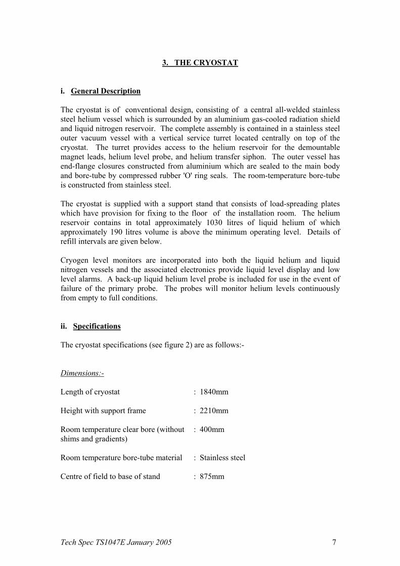
3. THE CRYOSTAT
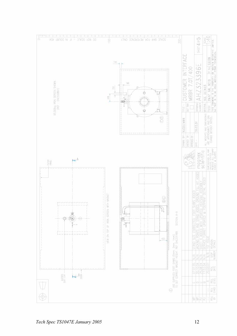
i. General Description The cryostat is of conventional design, consisting of a central all-welded stainless steel helium vessel which is surrounded by an aluminium gas-cooled radiation shield and liquid nitrogen reservoir. The complete assembly is contained in a stainless steel outer vacuum vessel with a vertical service turret located centrally on top of the cryostat. The turret provides access to the helium reservoir for the demountable magnet leads, helium level probe, and helium transfer siphon. The outer vessel has end-flange closures constructed from aluminium which are sealed to the main body and bore-tube by compressed rubber 'O' ring seals. The room-temperature bore-tube is constructed from stainless steel. The cryostat is supplied with a support stand that consists of load-spreading plates which have provision for fixing to the floor of the installation room. The helium reservoir contains in total approximately 1030 litres of liquid helium of which approximately 190 litres volume is above the minimum operating level. Details of refill intervals are given below. Cryogen level monitors are incorporated into both the liquid helium and liquid nitrogen vessels and the associated electronics provide liquid level display and low level alarms. A back-up liquid helium level probe is included for use in the event of failure of the primary probe. The probes will monitor helium levels continuously from empty to full conditions. ii. Specifications The cryostat specifications (see figure 2) are as follows:- Dimensions:- Length of cryostat : 1840mm Height with support frame : 2210mm Room temperature clear bore (without : 400mm shims and gradients) Room temperature bore-tube material : Stainless steel Centre of field to base of stand : 875mm

Tech Spec TS1047E January 2005 8
Cryostat end flange to centre of field : 920mm Outside diameter : 1720mm Minimum ceiling height for : 3033mm service tools Weight of cryostat (excluding cryogens) : 5200kg (approx) Liquid helium cryogen details :- Volume for initial installation (includes : 2500 litres cooling the magnet from 77K to 4.2K, volume required to completely fill helium reservoir and top-up after magnet energisation) Recommended refill volume during : 190 litres normal operation Maximum volume of reservoir : 1030 litres Hold-time during normal operation : More than 45 days (static magnetic field, leads withdrawn) Liquid nitrogen cryogen details :- Volume for initial installation (includes : 4000 litres pre-cool of magnet to 77K and volume required to completely fill LN2 reservoir) Volume of reservoir : 170 litres nominal Refill volume : 170 litres nominal excluding transfer
losses Hold-time in static condition : More than 12 days

Tech Spec TS1047E January 2005 9
Figure 2 Drawing of cryostat

Tech Spec TS1047E January 2005 10

Tech Spec TS1047E January 2005 11
Tech Spec TS1047E January 2005 12

Tech Spec TS1047E January 2005 13

Tech Spec TS1047E January 2005 14
4. SYSTEM COMPONENTS 1 off 7T/400mm magnet system with integral s/c shims, housed in a low loss cryostat. 1 off Stand 1 off De-mountable main current lead 1 off De-mountable s/c shim current lead 1 off E5011 helium level monitor 1 off E5031 nitrogen level monitor 1 off Head oscillator 1 off E7002 emergency discharge unit 1 off Set of service cables (8.5m) 1 off Helium monitor cable 1 off Nitrogen monitor cable 1 off Flexible siphon (2.0m) 1 off Nitrogen blow-out tube 1 off Nitrogen ground level fill kit 1 off Spares kit 1 off De-mountable helium level probe 1 off De-mountable nitrogen level probe 1 off System manual

Tech Spec TS1047E January 2005 15
APPENDIX
7T/400 Passive Room Shield Guidelines Typical shield dimensions 3 m wide x 3 m tall x 5 m long
Magnex Scientific Ltd Doc ref :7T 400 shield.doc
7.0 T 400 m m room shie ld
0
2
4
6
8
10
12
0 20 40 60 80
tonnes
met
res ax ial f ield (m)
radial f ield (m)