
SPECIFICATION FOR 40.37 METRE 70 PAX - CREW … Tech Spec - Base Stock Boat.pdf · design will...
21
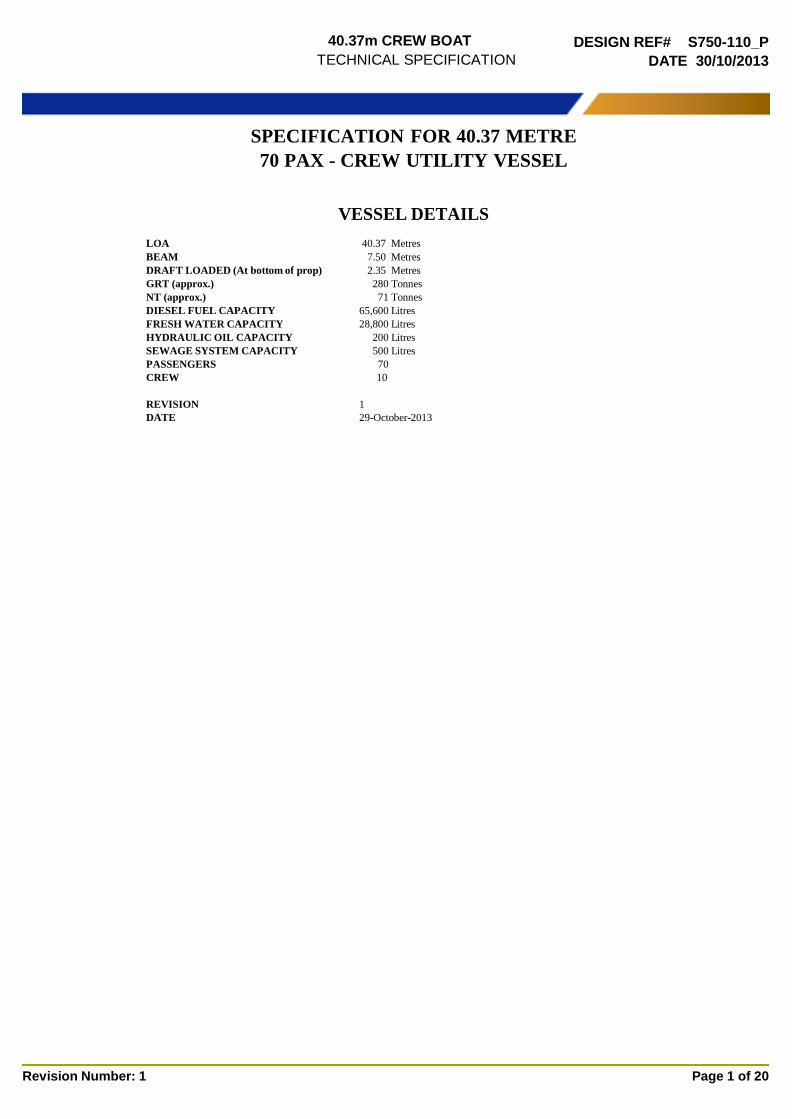
40.37m CREW BOAT TECHNICAL SPECIFICATION DESIGN REF# S750-110_P DATE 30/10/2013 Revision Number: 1 Page 1 of 20 SPECIFICATION FOR 40.37 METRE 70 PAX - CREW UTILITY VESSEL VESSEL DETAILS LOA 40.37 Metres BEAM 7.50 Metres DRAFT LOADED (At bottom of prop) 2.35 Metres GRT (approx.) 280 Tonnes NT (approx.) 71 Tonnes DIESEL FUEL CAPACITY 65,600 Litres FRESH WATER CAPACITY 28,800 Litres HYDRAULIC OIL CAPACITY 200 Litres SEWAGE SYSTEM CAPACITY 500 Litres PASSENGERS 70 CREW 10 REVISION 1 DATE 29-October-2013
-
Upload
vuongtuong -
Category
Documents
-
view
217 -
download
3
Transcript of SPECIFICATION FOR 40.37 METRE 70 PAX - CREW … Tech Spec - Base Stock Boat.pdf · design will...
40.37m CREW BOAT
TECHNICAL SPECIFICATION
DESIGN REF# S750-110_P
DATE 30/10/2013
Revision Number: 1 Page 1 of 20
SPECIFICATION FOR 40.37 METRE
70 PAX - CREW UTILITY VESSEL
VESSEL DETAILS
LOA 40.37 Metres
BEAM 7.50 Metres
DRAFT LOADED (At bottom of prop) 2.35 Metres
GRT (approx.) 280 Tonnes
NT (approx.) 71 Tonnes
DIESEL FUEL CAPACITY 65,600 Litres
FRESH WATER CAPACITY 28,800 Litres
HYDRAULIC OIL CAPACITY 200 Litres
SEWAGE SYSTEM CAPACITY 500 Litres
PASSENGERS 70
CREW 10
REVISION 1
DATE 29-October-2013


40.37m CREW BOAT
TECHNICAL SPECIFICATION
DESIGN REF# S750-110_P
DATE 30/10/2013
Revision Number: 1 Page 2 of 20
1.0 Design
The vessel will be designed to comply with the chosen classification society crewboat rules and OSV code for statutory matters. The
design will incorporate a central deck house with seating for 70 rig crew, with the bridge situated on the upper level incorporating two
control stations. All fuel oil and freshwater tanks will be constructed integrally to the hull. The vessels speed will be measured by
GPS during sea trials. The following speeds and load conditions will form the contract speeds.
Sea Trial Speed Requirements
Speed
23 knts
Load Condition 50 DWT Engine Power Output 85%
Speed
24 knts Load Condition 40 DWT Engine Power Output 85%
Speed
25 knts Load Condition 30 DWT Engine Power Output 85%
Conditions
Up to Sea State 3 (Beaufort Scale)
GPS speed will be recorded during trial. Vessel DWT to be confirmed by Client prior to sea trial 4 runs in total - two in each direction
Wind speed and direction, sea condition, current direction and weather conditions will be recorded during the trial.
Endurance 4 hour endurance trial at 100% MCR Personal Shipyard to supply all necessary personal for the trials. Deck loading 2 tonnes per m2 Deck Cargo Capacity 40 tonnes (approximate) Clear Deck Area 109m2 Noise Levels Noise levels in the bridge and main passenger deck cabin not to exceed 75 Dba in
general at 85% MCR
1.1
Construction Class
The vessel will be constructed in accordance to Lloyds Register of Shipping - Rules and Regulations for the Classification of Special
Service Craft, 2013. Plan approval, survey during construction, and attendance at sea trials will be completed by LR. Stability will be
designed in accordance to OSV code for vessels below 500 GT and without double bottoms. A letter will be obtained by the owner from
flag authority to authorise Class to carry out stability review according to OSV code for vessels below 500 GT without double bottoms
and Life Saving Equipment according to IACS Rec.99 (Recommendations for the Safety of Cargo Vessels of less than Convention Size):
Owner will provide exemption letter from flag authority for an exemption to use only single shot Co2 system. Safety plan will be
approved by flag authority (At Owner's arrangement)
Notation: .+100A1 SSC WORKBOAT MONO G4 ‘service area’, +LMC
Plan Approval Completed by Class
Class Survey Costs Included for above notation.
Inclining Experiment / Stability Included
Loadline Calculation / Certificate Included.
Class Certificate of Survey Included for above notation.
Safety Certificate Flag Authority (Owner's arrangement)
Cargo Ship Radiotelephony Certificate Included
Ship Sanitation Exemption certificate Included
Flag State and Registration TBA - owners arrangement
40.37m CREW BOAT
TECHNICAL SPECIFICATION
DESIGN REF# S750-110_P
DATE 30/10/2013
Revision Number: 1 Page 3 of 20
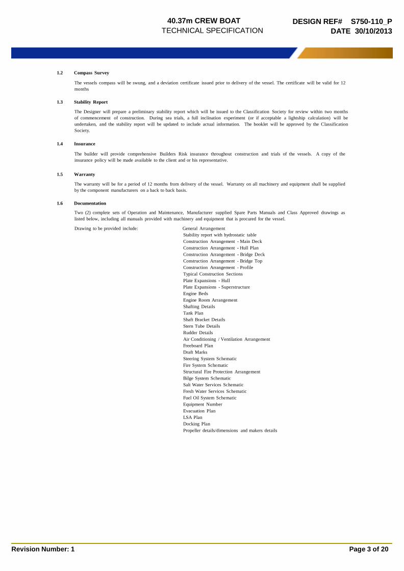
1.2 Compass Survey
The vessels compass will be swung, and a deviation certificate issued prior to delivery of the vessel. The certificate will be valid for 12
months
1.3 Stability Report
The Designer will prepare a preliminary stability report which will be issued to the Classification Society for review within two months
of commencement of construction. During sea trials, a full inclination experiment (or if acceptable a lightship calculation) will be
undertaken, and the stability report will be updated to include actual information. The booklet will be approved by the Classification
Society.
1.4 Insurance
The builder will provide comprehensive Builders Risk insurance throughout construction and trials of the vessels. A copy of the
insurance policy will be made available to the client and or his representative.
1.5 Warranty
The warranty will be for a period of 12 months from delivery of the vessel. Warranty on all machinery and equipment shall be supplied
by the component manufacturers on a back to back basis.
1.6 Documentation
Two (2) complete sets of Operation and Maintenance, Manufacturer supplied Spare Parts Manuals and Class Approved drawings as
listed below, including all manuals provided with machinery and equipment that is procured for the vessel.
Drawing to be provided include: General Arrangement
Stability report with hydrostatic table
Construction Arrangement - Main Deck
Construction Arrangement - Hull Plan
Construction Arrangement - Bridge Deck
Construction Arrangement - Bridge Top
Construction Arrangement - Profile
Typical Construction Sections
Plate Expansions - Hull
Plate Expansions - Superstructure
Engine Beds
Engine Room Arrangement
Shafting Details
Tank Plan
Shaft Bracket Details
Stern Tube Details
Rudder Details
Air Conditioning / Ventilation Arrangement
Freeboard Plan
Draft Marks
Steering System Schematic
Fire System Schematic
Structural Fire Protection Arrangement
Bilge System Schematic
Salt Water Services Schematic
Fresh Water Services Schematic
Fuel Oil System Schematic
Equipment Number
Evacuation Plan
LSA Plan
Docking Plan
Propeller details/dimensions and makers details
40.37m CREW BOAT
TECHNICAL SPECIFICATION
DESIGN REF# S750-110_P
DATE 30/10/2013
Revision Number: 1 Page 4 of 20
2.0 Aluminium Construction Labour
All construction labour will be supplied by the yard, using tradesmen qualified and experienced in aluminium fabrication. Stringent
quality inspection systems are utilised as part of the yards normal operation.
2.1 Aluminium - Main Construction
Marine grade aluminium - 5083 plate and 6061 /6082 extrusions in accordance to the Classification Authorities Rules will be used for
construction. The structural integrity of the vessel is designed to comply with Survey Authorities regulations.
2.2 Fendering
Used aircraft tyres will be utilised around the vessel for fendering allowing the vessel to be protected during berthing operations or
alongside other vessels. All side tyres will be fitted with stainless steel wire and welded aluminium lugs. Wire lugs will be fitted
between each tyre to stop loss of multiple tyres in case of wire being severed. Transom and stern corner tyres will be installed with a
welded aluminium socket and bolted flange.
The number and size of tyres as follows:
Approx. 5 units of approx. 1150mm diameter across transom mounted with top of
tyre exposed above deck to allow helmsman to see tyre
1 unit of approx. 1250mm diameter on each stern corner
2 units approx. 1150mm diameter immediately fwd of the stern corners.
Approx. 27 units of approx. 685mm diameter along each shipside
2.2.1 Lashing Lugs
Approx. total 16 units 3 tonne SWL lashing lugs will be installed on port and starboard sides of the work deck approx. 2m apart as close
as possible to the crash rails. Each lug will be load tested to 1.2 times SWL and a statement of fact will be provided by the class society
witnessing the load and NDT testing.
2.3 Welding
All aluminium and stainless steel welding throughout the construction and outfitting of the vessel will be carried out in accordance to
welding procedures currently utilised by the Builder and approved by the Classification Society.
The Builders welding procedures will comply with international regulations and standards, and take into consideration alignment,
fairness, edge preparation and gap widths. Only Classification Society qualified and tested personnel will be utilised for hull and
structural welding.
Following the completion of the welding of the hull the Builder shall arrange for X-rays to be taken at locations indicated by the
Classification Society
2.4 Consumable Items
All consumable items required for the construction and outfitting of the vessel will be supplied by the yard. Consumable items will be
of a quality that they have no undesirable effect on non ferrous parts of the vessel. Filler wire shall be certified for use by the
Classification Society.
2.5 Ancillaries
Ancillary items such as fasteners, brackets etc. that are required for the normal completion of the vessel will be provided by the yard.
40.37m CREW BOAT
TECHNICAL SPECIFICATION
DESIGN REF# S750-110_P
DATE 30/10/2013
Revision Number: 1 Page 5 of 20
2.6 Surface Protection
2.6.1 Preparation
All painted surfaces will be cleaned and free from oil and grease. All painted external aluminium surfaces will be either grit blasted,
mechanically abraded or acid washed to remove oxidisation residues prior to the immediate application of a protective primer which will
be compatible with the next coats of the paint system.
All unpainted surfaces will be cleaned and acid washed
2.6.2 External Surfaces
The topsides above waterline and the superstructure will be left unpainted. These surfaces will be cleaned and acid washed.
The window areas will be painted black as per the general arrangement plan
Non-Skid deck paint will be applied to decks that are not covered with timber. All paint will be tin free.
All underwater areas will be coated with an approved tin free antifouling coating system providing 24 months protection. The paint
makers two year warranty for underwater area will be passed on to the client.
2.6.2.1 Hull Markings
Vessel name will be welded on using 4mm plate to bow and stern. Flag state welded to stern
Client Logo will be installed using vinyl sticker
Draft Marks will be welded plate 6mm
IMO number will be punched and painted onto superstructure sides and roof
Thruster marking punched and painted
Muster station painted on aft deck
Basket landing area painted on aft deck
Carving note engraved onto 4mm plate and welded to main deck beam
Rescue Zone painted in bright yellow with diagonal black stripes. The area will be 2m wide and extend from the main deck to the
waterline located at the forward part of the main deck
2.6.3 Internal Surfaces of Hull
All surfaces will be cleaned and free from oil and grease. No coatings will be applied to internal spaces, tanks or compartments.
2.6.4 Freshwater and Fuel Oil Tanks
All integral aluminium potable fresh and Fuel oil water tanks will be cleaned and free from foreign objects. No coatings will be applied
to tanks.
2.6.5 Pipe work Colour Codes
Pipe work will be colour coded by way of internationally recognised identification stickers. Stickers will be placed approx. every one
metre or where they are most visible. The following schedule of colours for liquid identification will be utilised where applicable.
Bilge: Black.
Fire Main: Bright Red.
Fresh Water System - Cold: Blue.
Fresh Water System - Hot: Blue with red bands.
Fuel Oil: Yellow.
Lube Oil: Brown.
Hydraulic Oil: Purple.
Sea Suctions: Green.
Sea Water Cooling: Light Green.
Compressed Air: White.
2.7 Decking
The work deck will be timber sheathed. The sheeting will be held in position by use of angle bars and tee bars welded to the main deck
with planking prepared to allow for expansion and swelling of wet timber under normal operating conditions. Care will be taken to keep
all timber flush and minimise gaps. Timber details as follows:
Timber Treated Pine or similar
Arrangement As per general arrangement drawing.
Thickness Approximately 35mm
3.0 Mechanical Engineering Labour
All engineering labour will be supplied by the yard, using tradesmen qualified and experienced in the outfitting of aluminium vessels.
Stringent quality control systems are utilised as part of the yards normal operation.
3.1 Sub Contract Labour
When deemed necessary, the yard may utilise sub-contract labour for such items as stainless steel pipe spooling etc. Such labour will be
drawn from approved contractors, and will be subject to direct supervision from the yards management. The sub-contractors will also be
subject to the yards quality control systems.
40.37m CREW BOAT
TECHNICAL SPECIFICATION
DESIGN REF# S750-110_P
DATE 30/10/2013
Revision Number: 1 Page 6 of 20
3.2 Main Propulsion Engine and Gearbox - Option 1
The vessel will be fitted with Triple marine diesel main propulsion engines. The main engines will be equivalent to the following
specification.
Engine Make Cat
Engine Model C32
Rating 1300HP @ 1800RPM
Gearbox Make Twin Disc
Gearbox Model MGX 6690 SC Quickshft
Reduction Ratio 2.47:1
Trailing Pump Fitted
Engine Rating as nominated by Manufacturer
For vessels operating at rated load and rated speed upto 50% of the time, or 6 hours out of 12, with cyclical load and speed (20% to 80%
load factor).
Main Engine Instruments
Caterpillar factory standard local operating panel plus Fwd station and aft station as below.
Aft Station
tacho
engine temp
off/on/start switch
stop pushbutton
panel light dimmer
40.37m CREW BOAT
TECHNICAL SPECIFICATION
DESIGN REF# S750-110_P
DATE 30/10/2013
Revision Number: 1 Page 7 of 20
3.2.1 Main Propulsion Engine and Gearbox - Option 2
The vessel will be fitted with Triple marine diesel main propulsion engines. The main engines will be equivalent to the following
Engine Make Cummins
Engine Model KTA 38 M2 Tier 2 with Electronic Governor
Rating 1350 BHP @ 1900RPM
Gearbox Make Twin Disc
Gearbox Model MGX 6690 SC - Stand Alone Mount
Reduction Ratio 2.47:1
Trailing Pump Installed
Engine Rating as nominated by Manufacturer
Heavy Duty (HD)
Intended for continuous use in variable load applications where full power is limited to eight hours out of every ten hours of operation.
Also, reduced power operations must be at or below 200 rpm of the maximum rated rpm. This rating is an ISO 3046 fuel stop power
rating and is for applications that operate less than 5,000 hours per year.
Main Engine Instruments
Cummins factory standard local operating panel plus Fwd and Aft station as per below:
Local Operating Panel (LOP)
tacho/hour meter
water temp
crank case press
gear oil press
engine oil press
exhaust temp
common warning lamp
system power lamp
start & stop pushbutton
remote/off/local toggle switch
Fwd Station
tacho
water temp gear
oil press engine
oil press
high water temp warning lamp low
gear oil press warning lamp low
engine oil press warning lamp
audible alarm
start key & stop pushbutton
panel light dimmer
Low oil pressure shutdown
Overspeed shutdown
High coolant temperature shutdown
Low water level alarm
Aft Station
tacho
engine temp
off/on/start switch
stop pushbutton
panel light dimmer
40.37m CREW BOAT
TECHNICAL SPECIFICATION
DESIGN REF# S750-110_P
DATE 30/10/2013
Revision Number: 1 Page 8 of 20
3.3 Engine Control
The engine and gearbox control will be an electronic system Twin Disc EC300 or equal. Installation and commissioning will be
completed by the yard in conjunction with the engine and gear box supplier. The vessel will be equipped with two control stations. One
control station located starboard forward on the bridge and one facing aft in the rear of the bridge / wheelhouse. The engines may be
paired (port & Starboard) depending on final configuration and interfacing by the control system.
3.4 Shafting
The propulsion shafts will be machined from Aquamet 17 or similar stainless steel of suitable strength. Each shaft will be machined with
a 1:12 taper and be reversible. The propellers and couplings will be designed in accordance to Classification Society guidelines.
Shaft Material: Aquamet 17/4ph or similar Stainless Steel
Shaft Diameter: TBA - To meet Class
Taper: 1:12
Stern Tubes: Aluminium, water cooled bearings.
Shaft Brackets: Cast Steel P brackets choc fast and bolted into hull pockets
3.5 Rudders and Ancillary Equipment
The twin (2) rudders will be fabricated from Marine Grade stainless steel. They will be of faired construction. The rudder shafts will be
of marine grade stainless steel shafting of a diameter which will comply with load calculations and approved by Class. The rudders will
be operated by hydraulically powered cylinders, and be equipped with steel tiller arms and painted steel tie bar.
3.6 Shaft and Rudder Bearings
The propulsion shafts will be fitted with Orkot or equal composite bearings. The bearings will be water cooled and lubricated. The
stern tubes will be constructed of heavy walled aluminium pipe. Bearings will be chocfast in Bronze or 316 stainless steel housings to
ensure precision alignment. Each Propulsion shaft will be fitted with an earthing device. Shafts seals will be Eagle mechanical type
The rudder bearings will be machined from Orkot or equal bearing material, the rudder tube will be fitted with a gland packing seal.
3.7 Propellers
The vessel will be fitted with Triple nickel aluminium bronze FIVE bladed propellers. The diameter will be as calculated by the
Designer to attain the required performance and the taper of the shaft boss will be 1 : 12. An approved locking system will be fitted to
ensure propeller security.
40.37m CREW BOAT
TECHNICAL SPECIFICATION
DESIGN REF# S750-110_P
DATE 30/10/2013
Revision Number: 1 Page 9 of 20
3.8 Auxiliary Gensets - Option 1
The vessel will be fitted with two marine generators with approximately 86 ekw capacity each. Local operating panels will be supplied
by the manufacturer, there will be no controls on the bridge. Specification as follows;
Engine Make Cat
Output 86kw
Engine Model: C4.4
3.8.1 Auxiliary Gensets - Option 2
The vessel will be fitted with two marine generators with approximately 80 ekw capacity each. Local operating panels will be supplied
Engine Make Cummins
Output 80 ekw 50 hz 3 ph 415v
Engine Model: 6BT 5.9M Type approved
134 bhp @ 1500rpm – Prime power rating
Engine mounted heat exchanger cooling system
SAE 3 Flywheel & Housing
Electronic governing
24 v DC electrics
Alternator: UCM274E Single Bearing build
Voltage Connection – 415V
IP23 enclosure
3 Phase 4 Wire
Control System – MX341 AVR + PMG
SAE 3
No of poles (4)
Anti condensation heater (220-260V AC)
Generator Instrument Panel: Engine Room Panel –Remote Mounted
Unclassed LCD graphic display shows icons, symbols and bar graphs for intuitive operation.
40.37m CREW BOAT
TECHNICAL SPECIFICATION
DESIGN REF# S750-110_P
DATE 30/10/2013
Revision Number: 1 Page 10 of 20
3.9 Engine Mounting Systems
The main propulsion engines and auxiliary engines will be mounted on flexible mounts over aluminium engine beds.
Engine Mounts Resilient mounts Gearbox Mounts Hard Mounted
3.10
Genset Mounts
Steering System
Manufacturers Standard supply soft mounts
The steering system will be an electrically powered hydraulic system with single electric motor Scandia brand from Norway or equal
Pump Single Hydraulic pump driven by 3 phase electric motor.
Tiller Arms Steel class approved
Steering Rams Twin Class approved
Helm Unit Electric non follow up joy stick, one fwd station and one aft station
Emergency Steering Steering wheel located in Tiller Flat with intercom headset for bridge
communications
3.12 Anchor Winch
An electric/hydraulic drum type anchor winch model Hypac or equivalent will be installed to the forward deck. The winch will have a
drum suitable for wire anchor cable and a brake. Control will be suitable weather tight local panel. The winch will be covered with a UV
resistant canvas cover and draw string.
3.13 E/R Ventilation
The engine room air intake system will utilise two fans which will be driven by 415/3/50 electric motors, and may be run from either
generator. Air flow will be sufficient to keep the engine room temperature within tolerable limits for the machinery in tropical
conditions and supply the air required by the main engines and the generator sets.
The engine room air exhaust will be natural ventilation
Both the air in and the air out ventilators will be fitted with remotely operated fire flaps that can be operated from outside the engine
room.
The fan inlets and outlets will be positioned at the fwd and aft ends of the engine room to provide maximum air flow.
3.14 Piping - General
All piping will be arranged according to good marine practice and be sized for the purpose intended. The pipes will be securely clamped
to the vessels structure, fittings and bends will be of approved type and kept to a minimum. All piping will be colour coded in
accordance to Internationally recognized standards.
All sea water piping will have flanged connections and be spooled to avoid possible leakage onto electrical switchboards or electrical
components
All pressure pipes will be fitted with a suitable pressure gauge
3.15 Exhaust Systems
The main and auxiliary engines will be fitted with fabricated steel exhaust systems. The systems will be insulated with suitable lagging
in hot areas between the expansion bellows and the water injection point. Water injection will be stainless steel and be prior to the
connection at the ship side, which will eliminate sparks and ensure the hull penetration is cooled.
40.37m CREW BOAT
TECHNICAL SPECIFICATION
DESIGN REF# S750-110_P
DATE 30/10/2013
Revision Number: 1 Page 11 of 20
3.16 Fresh Water System
The fresh water supply will be stored in aluminium double bottom tanks, constructed integrally to the hull. The system will be fitted
with a single phase constant pressure pump to service the domestic area. Details of the fresh water system are as follows:
Capacity: Total approximate Capacity : 28,600 Litres
Cargo Transfer Pump: Varisco JP06-220-TWGMC, (or equivalent) 13.5cub.m/hr @ 55m head, 415V,
50Hz c/w Viton sealing system. The inlet and outlet will be flanged connection
and fitted with pressure gauges
Cargo Transfer Flow Meter: 2" Liquid Control or equivalent come with resettable counter and non resettable
totalizer and plumbed in line to transfer system. Come with calibration certificate.
Transfer Hose: One 30m x 2" transfer delivery hose with suitable quick release couplings each
end.
Cargo Piping: Aluminium / ABS plastic to cam lock fitting on deck.
Domestic Fresh Water Pump: One set Domestic fresh water pressure set 70LPM x 20mtr head
Hot Water System: Approx. 80 Litre 240/1/50 - Rheem Domestic System (or equivalent)
Domestic Piping: PVC and aluminium
Deck Outlets 1 x Outlet forward and 1 x outlet amidships will be installed for fresh water wash
down.
Monitoring
Sounding pipe will be provided for manual monitoring of fresh water tank level.
3.17 Raw Water Systems
Sea chests will be installed for the provision of salt water to fire pumps, main and auxiliary engine heat exchangers and air conditioning
condensers. The opening area of grating will be at least four (4) times the area of the suction valves provided at the sea inlet box.
Anodes will be installed to the inside of the sea strainers and sea chests. The surface treatment inside the sea chests and the grating will
be the same as the underwater area of the vessel. All sea strainers will have flanged connections.
The following sea strainers will be provided: 3 x Main engine
2 x Genset
1 x General service pump
3.18 Wet Areas - Domestic Plumbing
The vessel will have three marine style toilets. Two installed on the rig crew deck and one at the lower accommodation deck, one in a
single compartment for rig crew use, and two in a compartment combined with the shower for crews use. The toilet systems will flush
with fresh water by using a 230 volt pump with pressure set. A laundry room will be situated on the main deck aft of the rig crew area.
Details as follows:
Toilets: 3 Units - Domestic type - Western style.
Black Water Discharge: PVC / Aluminium piping - sized to suit, plumbed to the 500 litre holding tank. A
bypass line will be installed to allow the waste to discharge directly overboard if
required.
Main Holding Tank: The 500 litre sullage tank will be constructed of Aluminium and painted
internally. A pipe will be fitted to allow for waste to be sucked from the main
deck level. Valves will be installed to allow for future sewage treatment plant
Piping and Valves: PVC / Aluminium - Sized to suit.
Flushing System: Toilets - Fresh water flushing gravity fed to sewage tank.
Washing Machine: Samsung 7 kg - front loading. (or equivalent)
Clothes Dryer: Samsung 7 kg - front loading. (or equivalent)
Shower: Hot and cold water plumbed to showers.
Galley Sink: Hot and cold water plumbed to galley.
Grey Water Discharge: PVC / Aluminium piping - sized to suit, all grey water plumbed directly
overboard.

40.37m CREW BOAT
TECHNICAL SPECIFICATION
DESIGN REF# S750-110_P
DATE 30/10/2013
Revision Number: 1 Page 12 of 20
3.19 Bilge Pumping System
The bilge system will be a manifold system as follows:
Bilge Manifold and piping The bilge manifold will be mounted in the compartment immediately forward of
the engine room and constructed from grade 316 stainless steel. The bilge
pickups will be mounted at the lowest point in each compartment and plumbed to
the bilge manifold. The forepeak bilge suction will be by suitably sized hand
operated pump mounted on the foredeck. Each suction point will have a
removable filter.
Piping 316 Stainless Steel. All connections will be flanged type
Valves Bronze flange type SDNR and SD screw type valves
General bilge/service pump 1 x DESMI (or equivalent) capacity 30cub.m/hr, 54m head, suction 70dia,
discharge 50dia. To Double as ships fire pump and backup air/con pump. Inlet
and outlets will be flanged connections and have pressure gauges fitted.
Backup GS pump Additional standby pump for general service pump and plumbing (same model as
above)
Bilge Alarms Approved bilge alarms to each compartment.
3.20 Fuel Oil System
The fuel oil tanks will be constructed integrally to the vessels structure with the pickups 300mm from the bottom of the tanks. The total
capacity will be approximately 65,600 in four main tanks plus two day tanks. The fuel purifier will feed the day tanks. Details as
follows:
Day tank High and low level alarms fitted as per class requirement
Piping Grade 304 Stainless steel. All transfer piping will be flanged type. All fuel pipe
fittings will be flanged or steel JIC type fittings
Valves Brass.
Manifold Grade 304 or 316 Stainless Steel.
Fuel Filters Racor 1000FG duplex or equivalent primary filters to mains and 500FG for
auxiliaries.
Cargo Transfer Pump: Azcue (or equivalent) approx. 13.5cub.m/hr @ 50m head, 415V, 50Hz c/w Viton
sealing system. The inlet and outlet will be flanged connection and fitted with
pressure gauges. Pump will be connected to a manifold for transfer overboard or
between the ships fuel tanks
Cargo Transfer Flow Meter: 2" Liquid Control or equivalent come with resettable counter and non resettable
totalizer and plumbed in line to transfer system. Come with calibration certificate.
Flow meter will have a ticket printer. Come with calibration certificate.
Fuel Purifier 1 x Wesfallia or equivalent sized to suit fuel consumption.
A portable aluminium tank of approx. 50 litres will be installed for waste
An overflow alarm will be fitted and wired to the main alarm panel
Fuel Emergency Shut off System Via water tight Morse cable to main deck alongside CO2 release
Monitoring Sounding pipe will be provided for manual monitoring of Fuel tank levels.
40.37m CREW BOAT
TECHNICAL SPECIFICATION
DESIGN REF# S750-110_P
DATE 30/10/2013
Revision Number: 1 Page 13 of 20
3.21 Battery Boxes
Batteries will be housed in aluminium or GRP storage containers with lids and battery chocks will be fitted. Vents will be fitted in
accordance with the Classification Societies requirements.
3.22 Cathodic Protection
Zinc anodes will be fitted to the hull, sea inlets and internal pipe work to reduce Cathodic corrosion. The hull anodes will be bolted to
brackets recessed into the hull and to brackets across the aft of the transom, and the internal anodes will be pencil type anodes fitted to
sockets welded into the pipe work, a large anode will be bolted inside each of the sea inlet boxes. Hull protection will be designed to last
for 2 years.
3.23 Insulation
Thermal insulation will be installed into the passenger and bridge decks.
A-60 Fire protection insulation will be installed within the engine room, galley and at areas determined by the class society. The galley
and bridge will have A-60 rated fire doors.
3.25 Fire Protection System
The vessels fire protection and control and monitoring systems will be in accordance to current regulations. System details will be as
follows:
Machinery Space System Single Shot CO2 with manual release mechanism outside the E/R. When
activating the CO2 system, the fire alarm will sound approximately 25 seconds
before CO2 is released into the engine room. The emergency manual release will
be located in the CO2 room inside a control box to allow the Co2 room door to
open without sounding an alarm.
Monitoring Heat and smoke detectors will be installed throughout necessary compartments as
required. The main alarm monitoring panel will be mounted at the bridge and will
be an Tetra brand or equivalent.
Fire Pump - Main 1 x DESMI (or equivalent) capacity 30cub.m/hr, 54m head, suction 70dia,
discharge 50dia. To Double as ships fire pump and backup air/con pump. Inlet
and outlets will be flanged connections and have pressure gauges fitted.
The main fire pump will be plumbed into the fire fighting system using gate
valves and non return valves for choosing between bilge suction or emergency fire
fighting.
4 x Fire Hoses and Nozzles will be installed around the vessel.
Fire Extinguishers Listed in Survey and Safety Equipment Section Below
40.37m CREW BOAT
TECHNICAL SPECIFICATION
DESIGN REF# S750-110_P
DATE 30/10/2013
Revision Number: 1 Page 14 of 20
4.0 Interior Outfitting Labour
All interior outfitting labour will be supplied by the yard using tradesmen qualified and experienced in the outfitting of aluminium
vessels. Stringent quality checking systems are utilised as part of the yards normal operation.
4.1 Structural Doors and Hatches
Suitable marine water tight and weather tight doors and hatches will be installed as per the General Arrangement drawing as follows
Bridge Deck Single lever action Weather tight door
Main passenger deck Single lever action Weather tight doors installed to fwd and aft bulkheads. Single
Weather tight door Windows West or equal installed to stair case leading to lower
deck. Single A30 fire door installed to staircase leading to bridge deck
Lower Deck Single lever action aluminium water tight doors installed to bulkheads 14,20 and
37. Single lever action steel A60 water tight doors installed to bulkheads 25 and
33 (engine room)
Hatches main deck Aluminium single lever action water tight raised hatches installed to tiller flat and
collision bulkhead. One single lever action raised steel A60 hatch for engine room
escape. One aluminium flush hatch installed in fwd main deck passenger area for
lower accommodation escape
4.2 Windows - Wipers
Toughened safety glass windows in accordance to Survey Authorities regulations will be attached to the vessel using a class approved
gluing procedure, they will be arranged as per the General Arrangement plans.
Four Hepworth (or equivalent) 24 Volt marine windshield wipers will be installed to the forward screen and one will be fitted to the aft
control station. Fresh Water Washers will be installed to both forward and aft screens. The control panel will have speed control.
4.3 Upper Deck and Bridge Outfit - General
4.4
The linings and furniture for the upper deck and bridge will comprise a simple but aesthetically pleasing layout. The main helm position
will be to starboard, and the console layout will be designed ergonomically to enable the Master to operate the vessel and ships
electronics from the helm position. The aft console shall duplicate all necessary controls for manoeuvring the vessel and shall be finished
in the same manner as the forward console.
All instrumentation will have a dimmer switch or protection cover for night navigation
All shutdown switches will have protection to avoid accidental shutdown
The main helm and engineer's seats will be free standing and adjustable. A suitable chart table will be provided.
A curtain will be installed around the chart table for night navigation. A suitable chart light will be provided
The forward console will house all engine controls, electrical switchboards, alarm panels and equipment as included in equipment
schedules, defined elsewhere in this specification.
Main Deck
The main crew deck will be designed to accommodate seating for 70 Rig personnel. Two toilets are included on this level. The main exit
will be from the aft deck, and the emergency exit will be from the foredeck. There will be a deck store area opening onto the aft deck.
Marine non - skid vinyl floor covering will be installed.
The general layout will be as per the General Arrangement plans provided.
Passenger Seating 70 Beauteaux or equal economy class fixed back marine seats with vinyl
coverings, shared armrests, life jacket holder and seat belts to fwd seats.
The following amenities will be provided for Rig personnel.
Television 2 unit wall mounted 40" LED. Four additional TV speakers will be installed in
the main passenger area for safety video presentation
DVD 1 x Unit DVD wired into both main deck TV's
Hi Fi Stereo System AM / FM / CD Portable Hi Fi System will be installed.
Drinking Fountain Hot and cold water fountain.
Dimmer switch A dimmer switch will be installed for all main deck cabin lights
Lights All lighting will have individual labelled switches
First Aid Room A single cabin will be installed as per the general arrangement plan. The cabin
will have a single bed with removable rails and storage under with drawers and
locker. A single desk will be installed with drawers, desk lamp and suitable office
chair. A curtain will be installed on the window. Medical kit and stretchers will
be installed in this cabin
40.37m CREW BOAT
TECHNICAL SPECIFICATION
DESIGN REF# S750-110_P
DATE 30/10/2013
Revision Number: 1 Page 15 of 20
4.5 Crews Quarters
The lower accommodation will contain four twin berth cabins and two single berth cabins. Each berth will have a reading light and one
single phase GPO. Outfit will include basic wall panelling and head linings. Hanging space and robe type shelves will be installed for
stowage of personal effects. Floors will be aluminium with suitable marine vinyl non skid covering.
4.6 Galley
The galley will be designed to cater for ten crew and will be enclosed with A-60 insulation and fire door. The following domestic
equipment will be installed.
Stove Electric 4 burner Cook top with fiddle rack
Oven 1 domestic type
Range hood Custom SS with extractor fan
Microwave Medium capacity domestic type
Sink Deep double sink with spill rails around sink
Waste food grinder Insinkerator waste food grinder installed to galley sink
Fire Blanket A fire blanket will be installed in the galley.
Chiller / freezer 1 domestic chiller / freezer will be located in lower deck store compartment
beside galley . Capacity : 700L + 700L
Dining arrangements will be as shown on the General Arrangement plans. Seating will be upholstered with standard vinyl coverings.
Floor coverings in the galley and dining area will be easily cleanable vinyl and a Stainless Steel splash guard will be fitted around the
stove.
The following equipment will be installed for crew use
Television 1 x 32" LED Television.
DVD 1 x Unit DVD.
Hi Fi Stereo System AM / FM / CD Portable Hi Fi System will be installed.
40.37m CREW BOAT
TECHNICAL SPECIFICATION
DESIGN REF# S750-110_P
DATE 30/10/2013
Revision Number: 1 Page 16 of 20
4.7 Deck Coverings
Industrial vinyl and/or rubber flooring will be installed throughout internal accommodation decks and bridge deck. The following
schedule is provided as a guide.
Mess, Lounge, Crews Cabins: Vinyl or PVC fire retarding tiles or sheets.
Wet Areas and Galley: Epoxy two pack paint and Pirelli studded rubber flooring
Bridge Deck: Pirelli studded rubber flooring
All stores: Aluminium decks fitted with timber gratings where required.
4.8 Air Conditioning
Air conditioning will be installed to the main deck ,bridge and crew accommodation. Gas will be R404. Details as follows:
Compressor / Condenser: Twin sea water cooled units each serving separate compartments with
approximately 75% capacity per unit in case of one compressor failure the vessel
will have approx 75% backup cooling capacity.
Bridge: 2 x 13kw Ceiling mounted cassette plumbed to separate systems
Main Deck: 2 x 13kw Ceiling mounted cassette plumbed to separate systems.
Charter Cabins and hospital Wall mount AHU or ducted from concealed AHU
Crew Accommodation: Distributed by ducting from port and starboard AHU behind side lining. Port
system will be plumbed to separate system than stbd AHU. Four units approx 4kw
Raw water pump Single raw water pump will be provided and plumbed into both systems.
The general service pump will be plumbed into both condensers as a backup sea
water pump
4.9 Wet Areas
Three toilet compartments will be positioned as per the general arrangement drawing. Two compartments will have a shower installed.
Included in the compartments will be a domestic style toilet, and or hot/cold water shower, a hand basin, soap tray, toilet roll holder,
mirror and stainless steel grip rails. All toilet doors will have suitable signage. Only good quality shower fitting used. The shower
compartment floor will be shaped for good water drainage. Separate tap with short hose/nozzle will be provided beside each toilet
4.10 Timber and Laminates - General
The interior finishing of the vessel will be ergonomically designed for ease of maintenance, and pleasant appearance. Simple materials
that are easily cleaned and robust will be used throughout. Linings will be 3mm LamiPanel , Hexacore aluminium honeycomb panel on
the bulkheads and side panels and dampa ceiling system.
40.37m CREW BOAT
TECHNICAL SPECIFICATION
DESIGN REF# S750-110_P
DATE 30/10/2013
Revision Number: 1 Page 17 of 20
5.0 Electrical Installation - General
All electrical equipment, cables, cable trays and fittings that are required to complete the installation of the electrical fitout for the vessel,
as described below, will be supplied by the Builder. A full set of design drawings will be made available to the Builders Electricians.
All electrical installation labour will be sub contract labour organised and supplied by the Builder. The tradesmen will be qualified and
experienced in the outfitting of aluminium vessels. Stringent quality checking systems are utilised as part of the Builders operation.
Electrical apparatus and wiring systems will comply with the relevant rules and regulations of the Classification Society. All fittings
used will be of a good standard, and suitable for tropical and marine environment. Power supplies will be as follows:
1) 12V / 24V DC - for alarms, radio, navigational aids, emergency lighting, navigation lights and other emergency loads.
2) 230V , 1 phase, 50Hz - for general lighting and power less than 3kW, and communication and navigation equipment.
3) 415V , 3 phase, 50Hz - for ships power.
5.1 DC System (12V / 24V)
The extra low voltage system (12V / 24V DC) will be a marine system designed and installed in accordance to the Classification Society
regulations.
The extra low voltage supply for emergency supply for lighting and navigation aids will be obtained from two (2) banks of 24V, 250 AH
batteries.
A dedicated supply for radio communications will be obtained from two (2) banks of 24V, 120 AH batteries.
One static battery charger, 60 amp, 24V D.C. automatically regulated output will be installed for charging the above batteries.
5.2 AC System (230V - 1ph)
The single phase low voltage system (230V AC) will be a marine system designed and installed in accordance to the Classification
Society regulations. This system will be tapped from the 415V 3 phase system.
5.3 AC System (415VV - 3ph)
The three phase system (415V AC) will be a marine system designed and installed in accordance to the Classification Society
regulations.
5.3.1 Switchboard
The main switchboard will be dust and drip proof and dead front type with sheet Steel construction and self supporting framework,
complete with handrail and ventilation louvers suitable for marine duty to be installed in the auxiliary engine room.
The switchboard will be designed for the control of the Two diesel generators and feeder distribution with all indicators, knobs and
handles clearly marked by name plates.
The generators will be controlled by auto synchronization and load sharing on the main switchboard
There will be no Auto start system for the generators
5.4 Shore Power Connection
The shore supply cannot be synchronized with the generators.
A 415V AC 50Hz 50amp three phase and neutral shore supply system is offered as follows:
a) Shore supply inlet box complete with circuit breaker protection
b) Protection and monitoring at the main switchboard with interlocks so as to protect the system from inadvertent connection.
c) Monitoring to class requirements
5.5 Reefer Connections
4 x International 32 Amp reefer connections (415V AC/50Hz) will be provided as per class requirements at the main deck.
5.6 Ships Batteries
Ships batteries will be sized appropriately for the machinery installed and Classification Society regulations. Battery banks will include
the following:
Bank 1 Main engine - Starboard (able to parallel with other main engines)
Bank 2 Main engine - port (able to parallel with other main engines)
Bank 3 Main engine - centre (able to parallel with other main engines)
Bank 4 Generators and thruster engines
Bank 5 Ships general supply.
Bank 6 Emergency communications supply.
Bank 7 Emergency Supply
5.7 Lighting
12V / 24V DC lighting will be installed for navigation and emergency purposes. The vessels navigation lights will comply to
international regulations. Florescent lighting will be installed throughout the vessel for normal operations.
Two Water proof 400 W flood lights will be fitted on decks as appropriate.
All florescent lighting will be fitted with metal steel casing to avoid damage
40.37m CREW BOAT
TECHNICAL SPECIFICATION
DESIGN REF# S750-110_P
DATE 30/10/2013
Revision Number: 1 Page 18 of 20
6.0 Navigation Equipment
The following navigation and communication equipment will be installed. Client preference for alternative equipment of similar value
will be considered. The navigation and communication equipment will generally be compliant to regulations for vessels below 500Grt -
Sea Area 2. The package is not fully IMO HSC code compliant, and as such an exemption for some units may be required by flag. An
upgraded package is available by way of contract variation.
Note: Electronic models may change due to some models becoming obsolete prior to ordering. Replacement models will be equal to the
specified model
Radar 1 x JRC JMA-5212-4BB Marine X-Band Radar JRC JMA-5212-4BB
10kW UP-version / 4' open scanner, Echo Sounder JMC V-6810P 6.4" LCD . Track plotter / Fish Finder GPS Furuno Model GP-150 6 inch LCD Alpha/Numeric IMO approved GPS Navigator
Satellite Compass Vector G2 GPS Compass with additional aft station mono display and fluxgate
compass Auto Pilot Anschütz NautoPilot NP 60 with additional fluxgate compass
GMDSS Radio Communication for Sea Area 2 MF/HF SSB Radio 1 unit Furuno FS-2575 VHF DSC Radio 1 unit Furuno FM-8900S Navtex Receiver Furuno NX-700A Navtex Receiver (printer built in type) GMDSS EPIRB 1 unit McMurdo E5 Smartfind 406mgz fully automatic "wheelmark" & SOLAS
approved GMDSS SART 1 unit McMurdo Sart Radar Transponder Model S4, 9 Ghz GMDSS 2 Way Hand Held VHF Radio 2 x McMurdo VHF / Walkie Talkie Model R5 Including 84-210 Lithium Battery
Pack and 84-211 Nicad Battery, R2 12VDC Trickle charger Spare Batteries for GMDSS 2 Way Hand Held VHF
Radio 2 units McMurdo Lithium Battery for Model R5
SSAS Furuno SSAS PR-240L Talkback / PA / General Alarm "Vingtor" or equal Talkback / Public Address System / General Alarm system Sound Powered Telephone System CMR or Hanshin SPT system; 1 x SSB-401D Flush mount wheelhouse; 2 x SSW-
301B wall mount, 1 in engine room and steering room CCTV 6 Channel with UPS and two 500 GB external hard drive recording and colour
LCD monitor installed to bridge console, two camera in engine room, one camera
in pump compartment, two outdoor Weather proof vari focus Iris CCD Camera IR
illumination to 50 mtr installed at sides of vessel facing the aft deck area.
TV antenna TV350 Bantan Search Light 1 unit 1000W Sanshin or equal manual cabin control Searchlights with 360 deg
rotation. Horn Marco Pneumatic PW3-BB Magnetic Compass 1 unt Autonautic CHE-0071flush mount magnetic compass. AIS System Furuno FA-150 AIS BNWAS Le Guardian 2025 Night Vision Device 1 x set ''Yukon'' 'Tracker' or equal night vision binoculars, including in built
illuminator; 2 x 24mm; waterproof, to IP-65.
40.37m CREW BOAT
TECHNICAL SPECIFICATION
DESIGN REF# S750-110_P
DATE 30/10/2013
Revision Number: 1 Page 19 of 20
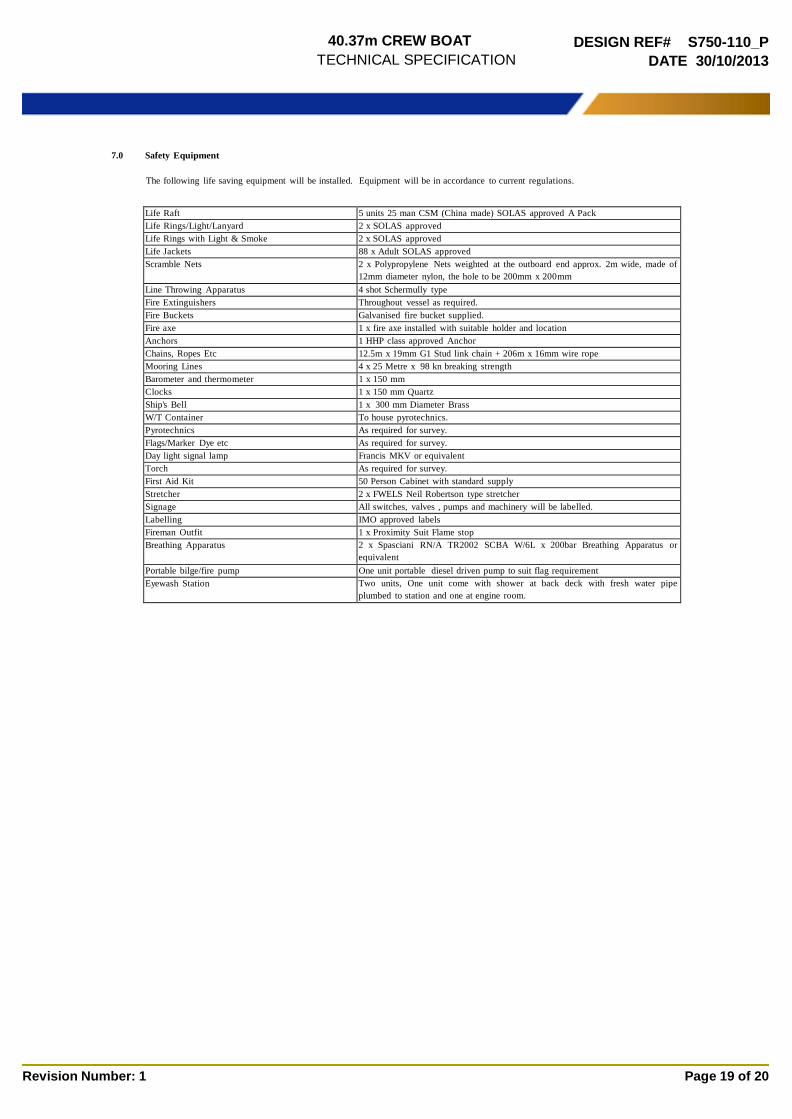
7.0 Safety Equipment
The following life saving equipment will be installed. Equipment will be in accordance to current regulations.
Life Raft 5 units 25 man CSM (China made) SOLAS approved A Pack Life Rings/Light/Lanyard 2 x SOLAS approved Life Rings with Light & Smoke 2 x SOLAS approved Life Jackets 88 x Adult SOLAS approved Scramble Nets 2 x Polypropylene Nets weighted at the outboard end approx. 2m wide, made of
12mm diameter nylon, the hole to be 200mm x 200mm Line Throwing Apparatus 4 shot Schermully type Fire Extinguishers Throughout vessel as required. Fire Buckets Galvanised fire bucket supplied. Fire axe 1 x fire axe installed with suitable holder and location Anchors 1 HHP class approved Anchor Chains, Ropes Etc 12.5m x 19mm G1 Stud link chain + 206m x 16mm wire rope Mooring Lines 4 x 25 Metre x 98 kn breaking strength Barometer and thermometer 1 x 150 mm Clocks 1 x 150 mm Quartz Ship's Bell 1 x 300 mm Diameter Brass W/T Container To house pyrotechnics. Pyrotechnics As required for survey. Flags/Marker Dye etc As required for survey. Day light signal lamp Francis MKV or equivalent Torch As required for survey. First Aid Kit 50 Person Cabinet with standard supply Stretcher 2 x FWELS Neil Robertson type stretcher Signage All switches, valves , pumps and machinery will be labelled. Labelling IMO approved labels Fireman Outfit 1 x Proximity Suit Flame stop Breathing Apparatus 2 x Spasciani RN/A TR2002 SCBA W/6L x 200bar Breathing Apparatus or
equivalent Portable bilge/fire pump One unit portable diesel driven pump to suit flag requirement Eyewash Station Two units, One unit come with shower at back deck with fresh water pipe
plumbed to station and one at engine room.

40.37m CREW BOAT
TECHNICAL SPECIFICATION
DESIGN REF# S750-110_P
DATE 30/10/2013
Revision Number: 1 Page 20 of 20
8.0 Launching
The vessel will be launched via suitable means at the construction facility. The yard will take full responsibility for launching
arrangements.
8.1 Equipment Hire
In the event that equipment is required to be hired for lifting or other purposes during construction of the vessel, the yard will take full
responsibility for arrangements and costs incurred.
8.2 Freight
Freight costs for delivery of components and equipment for the completion of the vessel will be borne by the yard.
8.3 Fuel & Lubricants
All fuel and lubricants required for commissioning and sea trials of the vessel will be provided by the shipyard.
8.4 Sea Trials
A comprehensive sea trial will be conducted in accordance to the yards strict sea trials plan, to satisfy the client and Classification
Society representative of the functionality of the vessel, and conformance to plans and specifications.
9.0 Delivery
The owner is to take delivery at Facility at the successful completion of sea trials, and receipt of final payment.


![Crew Accommodations - Crew Survival Guide - 29JUL2011[1]](https://static.fdocuments.net/doc/165x107/54f9c32b4a79590b398b479b/crew-accommodations-crew-survival-guide-29jul20111.jpg)


