SPECIFICATION AND DRAWINGS - APDCL...Specifications and Drawings Assam Power Distribution Company...
326
Bidding Document for Construction of Unmanned 33/6.6 KV New Substation i Specifications and Drawings Assam Power Distribution Company Limited BIDDING DOCUMENT FOR CONSTRUCTION OF NEW UNMANNED 33/6.6 KV SUB-STATIONS Design, Engineering, Manufacture, Assembly, Inspection, Testing at Manufacturer’s Works before Dispatch, Packing, Supply, Delivery at Site, Including Insurance During Transit, Subsequent Storage, Erection and Commissioning of Power Transformers With Associated Switchgears, including Supply & Erection of Substation Steel Structures, Construction of related Civil Works UNDER DEPOSIT SCHEME SPECIFICATION AND DRAWINGS (Employer’s Requirements) Volume - II BID IDENTIFICATION NO.
Transcript of SPECIFICATION AND DRAWINGS - APDCL...Specifications and Drawings Assam Power Distribution Company...

Bidding Document for Construction of Unmanned 33/6.6 KV New Substation i
Specifications and Drawings Assam Power Distribution Company Limited
BIDDING DOCUMENT
FOR
CONSTRUCTION OF NEW UNMANNED 33/6.6 KV SUB-STATIONS
Design, Engineering, Manufacture, Assembly, Inspection, Testing at Manufacturer’s Works before Dispatch, Packing, Supply, Delivery at Site, Including Insurance During
Transit, Subsequent Storage, Erection and Commissioning of Power Transformers With Associated Switchgears, including Supply & Erection of Substation Steel Structures,
Construction of related Civil Works
UNDER
DEPOSIT SCHEME
SPECIFICATION AND DRAWINGS
(Employer’s Requirements)
Volume - II
BID IDENTIFICATION NO.

Bidding Document for Construction of Unmanned 33/6.6 KV New Substation ii
Specifications and Drawings Assam Power Distribution Company Limited
VOLUME-2
TECHNICAL SPECIFICATION
CONTENTS
SECTION-1 SCOPE AND GENERAL TECHNICAL CONDITIONS 1
1.1.0 INTENT OF THE SPECIFICATION 1
1.2.0 SCOPE 1
1.3.0 CONTRACTOR TO INFORM HIMSELF FULLY 2
1.4.0 SERVICE CONDITIONS 3
1.5.0 CONFORMITY WITH INDIAN ELECTRICITY RULES & OTHER LOCAL REGULATIONS: 3
1.6.0 STANDARDS 3
1.7.0 CONTRACTOR’S REQUIREMENT 4
1.8.0 ENGINEERING DATA 4
1.9.0 DRAWINGS 4
1.10.0 FINAL DRAWINGS AND DOCUMENTS 6
1.12.0 DESIGN IMPROVEMENTS 6
1.13.0 DESIGN CO-ORDINATION 6
1.14.0 DESIGN REVIEW MEETING 6
1.15.0 QUALITY ASSURANCE, INSPECTION & TESTING 7
1.16.0 EMPLOYER'S SUPERVISION 9
1.17.0 INSPECTION & INSPECTION CERTIFICATE 9
1.18.0 TYPE TEST REPORTS 10
1.19.0 SPARE PARTS 11
1.20.0 GUARANTEED TECHNICAL PARTICULARS 12
1.21.0 PACKING 12
1.22.0 CONSTRUCTION TOOLS, EQUIPMENTS ETC. 12
1.23.0 MATERIALS HANDLING AND STORAGE 13
1.24.0 CONTRACTOR’S MATERIALS BROUGHT ON TO SITE 13
1.25.0 COMMISSIONING SPARES 14

Bidding Document for Construction of Unmanned 33/6.6 KV New Substation iii
Specifications and Drawings Assam Power Distribution Company Limited
ANNEXURE–I SCHEDULE OF QUANTITY (SUPPLY) 15
ANNEXURE–II SCHEDULE OF QUANTITY (ERECTION) 22
ANNEXURE–III SCHEDULE OF QUANTITY (MANDATORY SPARES) 28
SECTION-2 TECHNICAL SPECIFICATION FOR CONSTRUCTION
WORKS IN SUBSTATIONS 29
2.1.0 GENERAL 29
2.2.0 GEO-TECHNICAL INVESTIGATION 29
2.3.0 SCOPE OF WORK 29
2.4.0 SITE PREPARATION 30
2.5.0 SURFACE PREPARATION AND STONE SPREADING 30
2.6.0 SITE DRAINAGE 31
2.7.0 TRANSFORMER FOUNDATION AND OIL RECOVERY SYSTEM 31
2.8.0 CABLE TRENCHES 32
2.9.0 FOUNDATION AND RCC CONSTRUCTION 32
2.10.0 SECURITY FENCING, GATES AND SECURITY BOOTH 35
2.11.0 SUBMISSION 36
2.12.0 BUS BARS AND BUS BAR SUPPORTS 37
2.13.0 ACSR CONDUCTORS 37
2.14.0 ELECTRICAL CLEARANCES 38
2.15.0 EARTHING SYSTEM 38
2.16.0 PROTECTION AGAINST DIRECT LIGHTNING 40
2.17.0 INSULATORS AND HARDWARE FITTINGS 40
2.18.0 CLAMPS, CONNECTORS AND SPACERS 42
2.19.0 ILLUMINATION SYSTEM 42
2.20.0 STATION SERVICE SUPPLY 43
2.21.0 FIRE FIGHTING EQUIPMENT 43
2.23.0 SUBSTATION T & P 44
SECTION – 3 SPECIFICATION FOR DESIGN AND FEBRICATION 45 OF SUBSTATION STRUCTURES
3.1.0 SCOPE 45

Bidding Document for Construction of Unmanned 33/6.6 KV New Substation iv
Specifications and Drawings Assam Power Distribution Company Limited
3.2.0 MATERIALS 45
3.3.0 DESIGN PARAMETERS 46
3.4.0 DESIGN DRAWINGS 48
3.5.0 ACCESSORIES 48
3.6.0 FABRICATION 48
3.7.0 GALVANIZING AND PAINTING 48
3.8.0 EARTHING 48
3.9.0 TEST AND TEST CERTIFICATE 49
SECTION-4 TECHNICAL SPECIFICATION FOR POWER TRANSFORMERS 50
4.1.0 SCOPE 50
4.2.0 BIDDING 50
4.3.0 SPECIFIC TECHNICAL REQUIREMENTS (STANDARD CONDITIONS) 50
4.4.0 PERFORMANCE: 52
4.5.0 AUXILIARY POWER SUPPLIES: 52
4.6.0 DRAWINGS INCORPORATING THE FOLLOWING PARTICULARS SHALL BE SUBMITTED WITH THE BID: 52
4.7.0 SPARE PARTS: 53
4.8.0 WARRANTY 53
4.9.0 GUARANTEES 53
4.10.0 MISCELLANEOUS 54
4.11.0 NAME PLATE 55
4.12.0 GENERAL TECHNICAL REQUIREMENTS 55
4.13.0 DESIGN, STANDARDIZATION AND GENERAL CONSTRUCTION FEATURES. 58
SECTION – 5 TECHNICAL SPECIFICATION OF 33 KV & 6.6 KVAUTO RECLOSER 90
5.1.0 SCOPE 90
5.2.0 APPLICABLE STANDARDS 90
5.3.0 CLIMATIC CONDITIONS 90
5.4.0 TECHNICAL DATA SHEET FOR AUTO RECLOSER 91
5.5.0 DEFINITIONS AND ABBREVIATIONS 94

Bidding Document for Construction of Unmanned 33/6.6 KV New Substation v
Specifications and Drawings Assam Power Distribution Company Limited
5.6.0 Mounting 96
5.7.0 Bushings 96
5.8.0 Finish 96
5.9.0 Control equipment 97
5.10.1 General 97
5.11.0 Earth fault function 100
5.12.0 Sensitive earth fault (SEF) function 100
5.13.0 Auto-reclose operation parameters 101
5.14.0 Statistical measurement functions 101
5.15.0 Local control and indication: 102
5.16.0 Tele-control requirements 104
5.17.0 Local Engineering 106
5.18.0 Tele-control requirements 107
5.19.0 Communications 107
5.20.05.22.0 Power supplies 109
5.21.0 Maintenance and commissioning 110
5.22.0 Rating plate 110
5.23.0 Additional information 111
5.24.0 TESTS 112
5.25.0 PACKING/DOCUMENTATION 113
5.26.0 Documentation 113
5.27.0 SPECIAL TOOLS AND TACKLES 113
SECTION - 6 TECHNICAL SPECIFICATION OF OUTDOOR
CURRENT AND POTENTIAL TRANSFORMERS 114
6.1.0 SCOPE OF CONTRACT 114
6.2.0 STANDARDS 114
6.3.0 GENERAL REQUIREMENTS 114
6.4.0 COMMON MARSHALLING BOXES 115
6.5.0 TESTS 116
6.6.0 NAME PLATES 116

Bidding Document for Construction of Unmanned 33/6.6 KV New Substation vi
Specifications and Drawings Assam Power Distribution Company Limited
6.7.0 MOUNTING STRUCTURES 116
6.8.0 SAFETY EARTHING 116
6.9.0 TERMINAL CONNECTORS 117
6.10.0 PRE-COMMISSIONING TESTS 117
6.11.0 TECHNICAL DATA SHEET FOR CURRENT AND POTENTIALTRANSFORMERS117
SECTION - 7 TECHNICAL SPECIFICATION 122 FOR CONTROL AND RELAY PANELS
7.1.0 SCOPE 122
7.2.0 STANDARDS 122
7.3.0 TYPE OF PANEL 122
7.4.0 CONSTRUCTIONAL FEATURES 122
7.5.0 MOUNTING OF EQUIPMENTS 123
7.6.08.6.0 INTERNAL WIRING 123
7.7.0 TERMINAL BLOCKS 123
7.8.0 PAINTING 124
7.9.0 NAME PLATES AND MARKINGS 124
7.10.0 MISCELLANEOUS ACCESSORIES 124
7.11.0 EARTHING 125
7.12.0 RECORDING METERS (TRIVECTOR METERS) 125
7.13.0 RELAYS 131
7.14.0 PROTECTION SCHEME FOR PANELS 136
7.15.0 TESTS 137
7.16.0 PRE-COMMISSIONING TESTS 137
7.17.0 TECHNICAL DATA SHEET FOR THE RELAY AND CONTROL PANELS 138
SECTION -8 140 TECHNICAL SPECIFICATION OF ISOLATORS
8.1.0 SCOPE 140
8.2.0 GENERAL 140
8.3.0 DUTY REQUIREMENTS 140
8.4.0 CONSTRUCTIONAL DETAILS 141
8.5.0 EARTHING SWITCHES 142
8.6.0 OPERATING MECHANISM 142

Bidding Document for Construction of Unmanned 33/6.6 KV New Substation vii
Specifications and Drawings Assam Power Distribution Company Limited
8.7.0 OPERATION 142
8.8.09.8.0 TEST AND INSPECTION 143
8.9.0 CONNECTORS 144
8.10.0 SUPPORTING STRUCTURES 144
8.11.0 PRE-COMMISSIONING TESTS 144
8.12.0 TECHNICAL DATA SHEET FOR ISOLATORS 145
SECTION -9 147 TECHNICAL SPECIFICATION FOR SURGE ARRESTORS
9.1.0 SCOPE 147
9.2.0 STANDARDS 147
9.3.010.8.0 GENERAL REQUIREMENT 147
9.4.0 ARRESTOR HOUSING 148
9.5.0Error! Reference source not found.FITTINGS & ACCESSORIES 148
9.6.0 SURGE MONITOR 148
9.7.0 TESTS 148
9.8.010.10.0 NAME PLATE 149
9.9.0 PRE-COMMISSIONING TESTS 149
9.10.0 TYPE AND RATINGS 150
SECTION – 10 TECHNICAL SPECIFICATION OF BATTERY BANK AND CHARGER 152
11.1.0 SCOPE 152
11.2.0 BATTERY BANK 152
11.5.0 WATER 153
10.4.0 PLATE CONNECTION 153
10.5.0 BOLTS AND NUTS 153
10.6.0 TERMINALS 153
10.7.0 BATTERY RACKS 154
10.8.0 BATTERY CHARGING EQUIPMENTS 154
10.9.0 TESTS : 157
10.10.0 157 LTAC PANEL

Bidding Document for Construction of Unmanned 33/6.6 KV New Substation viii
Specifications and Drawings Assam Power Distribution Company Limited
SECTION - 11 159 TECHNICAL SPECIFICATION OF POWER AND CONTROL CABLES
11.1.0 GENERAL REQUIREMENT 159
11.2.0 TECHNICAL REQUIREMENTS 159
11.3.0 XLPE Power Cables 160
11.4.0 PVC Power Cables 160
11.5.0 DATA SHEET FOR CABLES 161
SECTION - 12 163 TECHNICAL SPECIFICATION OF 33KV & 6.6 KV XLPE
12.1.0 SCOPE 163
12.2.0 DEVIATION 163
12.3.0 : STARDARDS 163
12.4.0 ELECTRICAL CHARACTERISTICS & PERFORMANCE:- 164
12.5.0 CABLE CONSTRUCTION: 165
12.6.0 WOODEN DRUMS: 167
12.7.0 Tests to be performed as per IS:7098 (part II) 168
12.8.0 Descriptive literatures test results etc. 170
12.9.0 QUALITY ASSURANCE PLAN: 171
12.10.0 Guarantee: 171
SECTION - 13 TECHNICAL SPECIFICATION OF 6.6kV CAPACITOR BANK 172
13.1.0 172 SCOPE
13.2.0 STANDARDS 172
13.3.0 CAPACITOR BANKS 172
13.4.0 CIRCUIT BREAKER 175
13.5.0 ISOLATOR AND ISOLATOR-CUM-EARTHSWTICH 175
13.6.0 CURRENT TRANSFORMERS 175
13.7.0 SERIES REACTOR 175
13.8.0 FITTINGS AND ACCESSORIES 176
13.9.0 TESTS 176
13.10.0 DATA SHEET 178

Bidding Document for Construction of Unmanned 33/6.6 KV New Substation ix
Specifications and Drawings Assam Power Distribution Company Limited
SECTION - 14 TECHNICAL SPECIFICATION OF GALVANISED STEEL TUBULAR POLE 181
14.1.0 SCOPE 181
14.2.0 STANDARD : 181
14.3.0 Topography and Climatic Condition : 181
14.4.0 Materials : 181
14.5.0 Types, Size and construction : 181
14.6.0 Earthing Arrangements : 182
14.7.0 PRINCIPAL PARAMETERS 182
14.8.0 Tests and Test Certificates : 183
14.9.0 Marking : 183
14.10.0 Performance :- 183
14.11.0 Deviation :- 183
14.12.0 Guaranteed technical particulars : 183
SECTION - 15 TECHNICAL SPECIFICATION FOR GALVANIZED CHANNEL CROSS ARMS 184
15.1.015.1.0SCOPE : 184
15.2.0 Standards 184
15.3.0 GENERAL REQUIREMENT : 184
15.4.0 For galvanized channel : 185
15.5.015.5.0Data Sheet 186
SECTION - 16 TECHNICAL SPECIFICATION FOR DISTRIBUTION TRANSFORMER 187
16.1.0 SCOPE 187
16.2.016.2.0 BIDDING 187
16.3.0 STANDARDS 187
16.4.016.4.0GENERAL SERVICE CONDITION 188
16.5.0 GENERAL TECHNICAL SPECIFICATIONS: 189
16.6.0 SUPPRESSION OF HARMONICS 189
16.7.0 CENTRE OF GRAVITY 189

Bidding Document for Construction of Unmanned 33/6.6 KV New Substation x
Specifications and Drawings Assam Power Distribution Company Limited
16.8.0 GENERAL CONSTRUCTIONAL FEATURES 190
16.9.0 SURFACE PREPERATION & PAINTING 190
16.10.0 190 CORE (MAGNETIC CIRCUIT) AND CONSTRUCTIONAL FEATURES OF CORE
16.11.0 WINDING 190
16.12.0 INSULATION MATERIAL: 192
16.13.0 ACCESSORIES & FITTINGS 193
16.14.0 193 PROTECTION & MEASURING DEVICES
16.15.0 RADIATORS & VALVES 194
16.16.0 FITTINGS AND ACCESORIES 195
16.17.0 196 LOSSES
16.18.0 CAPITALISATION OF LOSSES AND LIQUIDATED DAMAGES FOR EXCESSIVE LOSSES: 196
16.19.0 Temperature rise: 197
16.20.0 197 TESTS & INSPECTION
16.21.0 197 REJECTION
16.22.0 DRAWINGS and CALCULATIONS FOR SUBMISSION WITH THE BID 197
16.23.0 QUALITY ASSURANCE PLAN: 198
16.24.0 198 DATA SHEET
16.25.0 GUARANTEE: 201
16.26.0 SCHEDULES: 201
16.27.0 DEVIATIONS: 202
SECTION-17 223 GUARANTEED TECHNICAL AND OTHER PARTICULARS
1.0 GENERAL 223
2.0 GUARANTEED TECHNICAL PARTICULARS OF 33kV /6.6kV TRANSFORMER 225
3.0 244 AUTO RECLOSER
4.0 CURRENT TRANSFORMERS (OUTDOOR) 248
5.0 POTENTIAL TRANSFORMER 252
6.0 254 RTU
7.0 261 CONTROL AND RELAY PANELS

Bidding Document for Construction of Unmanned 33/6.6 KV New Substation xi
Specifications and Drawings Assam Power Distribution Company Limited
8.0 GANG OPERATED SWITCH (ISOLATORS) 266
9.0 SURGE ARRESTOR 268
10.0 BATTERY 271
11.0 BATTERY AND CHARGER 274
12.0 DC DISTRIBUTION BOARD 275
13.0 TRIVECTOR METERS (For use with Relay & Control Panels) 277
14.0 279 11 KV DISC INSULATOR
15.0 GALVANIZED STEEL EARTHWIRE 280
16.0 33 kV POST INSULATOR 281
17.0 ACSR CONDUCTOR 282
18.0 33KV &11 kV CVT 285
19.0 33KV & 11 KV XLPE CABLE 286
20.0 GALVANISED STEEL TUBULAR POLE 292
21.0 DISTRIBUTION TRANSFORMER 294
SECTION-18 DRAWINGS 311

Bidding Document for Construction of Unmanned 33/6.6 KV New Substation 1
Specifications and Drawings Assam Power Distribution Company Limited
SECTION-1
SCOPE AND GENERAL TECHNICAL CONDITIONS
1.1.0 INTENT OF THE SPECIFICATION
1.1.1 This volume of the specification deals with the general technical information & criteria for design, manufacture, supply, erection, testing & commissioning and setting to work of construction of new substations on “Design, Supply and Install” basis.
1.1.2 The provisions of this section shall supplement all the detailed Technical Specifications and requirements brought out herein. The Contractor's proposal shall be based on the use of materials complying fully with the requirements specified herein.
1.2.0 SCOPE
1.2.1 The work involves design, engineering, manufacture, assembly, inspection, testing at manufacturer’s works before dispatch, packing, supply, including insurance during transit, delivery at site, subsequent storage, civil foundation work, erection and commissioning at site of various equipment and materials including power transformers, substation structures and civil foundations for equipment as specified in subsequent Clauses and Sections for two numbers unmanned sub-stations at Sadilapur and Pandu Ghat Water Supply Scheme.
1.2.2 The scopes of works also include site development, design & construction of boundary walls, fencing, gate and other facilities at substations as specified in the Bidding Document.
1.2.3 It is not the intent to specify completely herein all details of design and construction of the equipment and accessories. However, the equipment and accessories shall conform in all respects to high standards of engineering, design and workmanship and be capable of performing in continuous operation up to the bidder’s guarantees in a manner acceptable to the Employer. The Employer will interpret the meaning of drawings and specifications and shall be entitled to reject any work or material, which in his judgement is not in full accordance therewith.
1.2.4 Whether called for specifically or not, all accessories and work required for the completion of the work are deemed to be considered as a part of the Bidder’s scope, unless and until mentioned very clearly as excluded.
1.2.5 The major items of works included in the scope of this specification are listed below:-
i) Supply, erection, testing and commissioning of transformers and all switch & control gears such as circuit breakers, isolators, current transformers, relay & control panels, Lightning Arresters etc including mounting structures and civil foundations as specified in Bill of Materials.
ii) Supply, erection, testing and commissioning of Substation local Communication Equipment as specified in Bidding Document.

Bidding Document for Construction of Unmanned 33/6.6 KV New Substation 2
Specifications and Drawings Assam Power Distribution Company Limited
iii) Design, supply and erection of substation structure.
iv) Design and construction of cable trenches and earth mat including supply of all materials.
v) Other works includes site development, construction of Boundary Walls / Security Fencing, Design and installation of illumination system for switchyard etc as brought out in the Specification and Schedule of Requirements.
1.2.6 The name of substation that is to be built under the scope of this specification is listed below:
i) Sadilapur, 2 x 6.3 MVA, 33/6.6 kV and 2x1.5MVA, 33/0.433kV Substation (Guwahati, Assam)
ii) Pandu Ghat, 2 x 1.6 MVA, 33/6.6 kV and 2x250 KVA, 33/0.433kV Substation (Guwahati, Assam)
1.2.7 The various items of works are described very briefly in the schedule of Bid Form, Prices & Other Schedules. The various items as defined in these schedules shall be read in conjunction with the corresponding section in the technical specifications including amendments and, additions if any.
1.2.8 The Bidder’s rates shall be based on the description of activities in the schedules as well as necessary operations detailed in Technical Specifications.
1.2.9 The tentative Bill of Quantities are furnished in Annexure-I, Annexure-II and Annexure-III
at the end of this Section. Bidders are requested to note the following points:
i) The items mentioned in these Annexure shall only be used while preparing the
Price Schedules. If any items which is not specifically mentioned in Annexure- I
annexure-II and Annexure-III; but required to complete the works as per
Specification shall deemed to be included in any of the items of these
Annexure. Additions, deletions or modification of these items while preparing
the Price Bid by the Bidder shall render his bid non-responsive.
ii) The quantities are provisional in nature and for bidding purpose and for bid
comparison purpose only. Quantities may vary to the extent of (+) 15 % to (-)
15% in terms of total Contract Price.
1.3.0 CONTRACTOR TO INFORM HIMSELF FULLY
1.3.1 The contractor should ensure that he has examined the General Conditions, Specifications and Schedules as brought out in other sections and this Section and has satisfied himself as to all the conditions and circumstances affecting the contract price and fixed his price according to his own views on these matters and acknowledge that no additional allowances except as otherwise provided therein will be levied.
1.3.2 The Employer shall not be responsible for any misunderstanding or incorrect information obtained by the contractor other than information given to the contractor in writing by the Employer

Bidding Document for Construction of Unmanned 33/6.6 KV New Substation 3
Specifications and Drawings Assam Power Distribution Company Limited
1.4.0 SERVICE CONDITIONS
1.4.1 The plant and materials supplied shall be suitable for operation under the following climatic and other conditions:
a) Peak ambient day temperature in still air : 45°C
b) Minimum night temperatures : 0°C
c) Reference ambient day temperature : 45°C
d) Relative Humidity a) Maximum : 100 %
b) Minimum : 10 %
e) Altitude: Below1000 M above MSL
f) Maximum wind pressure : As per IS: 802 latest code.
g) Other Data: Refer Meteorological data pertaining to the locations.
h) Seismic Intensity ZONE-V as per IS 1893.
1.5.0 CONFORMITY WITH INDIAN ELECTRICITY RULES & OTHER LOCAL REGULATIONS:
1.5.1 The contractor shall note that all substation works shall comply with the latest provisions of Indian Electricity Rules and with any other regulations. Local authorities concerned in the administration of the rules and regulation relating to such works shall be consulted, if necessary, about the rules and regulations that may be applicable.
1.5.2 The Contractor shall also comply with the Minimum Wages Act 1948 and the payment of Wages Act (both. of the Government of India and State of Assam) and the rules made there under in respect of any employee or workman employed or engaged by him or his Sub-Contractor.
1.5.3 All registration and statutory inspection fees, if any, in respect of his work pursuant to this Contract shall be to the account of the Contractor. However, any registration, statutory inspection fees lawfully payable under the provisions of the statutory laws and its amendments from time to time during erection in respect of the Substation Works, ultimately to be owned by the Employer, shall be to the account of the Employer. Should any such inspection or registration need to be re-arranged due to the fault of the Contractor or his Sub-Contractor, the additional fees to such inspection and/or registration shall be borne by the Contractor.
1.6.0 STANDARDS
1.6.1 The equipment covered by this specification shall, unless otherwise stated be designed, constructed and tested in accordance with the latest revisions of relevant Indian Standards (ISS)/ IEC and shall conform to the regulations of local statutory authorities.
1.6.2 In case of any conflict between the standards and this specification, this specification shall govern.

Bidding Document for Construction of Unmanned 33/6.6 KV New Substation 4
Specifications and Drawings Assam Power Distribution Company Limited
1.6.3 Equipment conforming to other international or authoritative Standards which ensure equivalent or better performance than that specified under Clause 1.6.1 above shall also be accepted. In that case relevant extracts of the same shall be forwarded with the bid.
1.7.0 CONTRACTOR’S REQUIREMENT
1.7.1 The Contractor should be in possession of a valid H.V. Electrical Licence issued by the Chief Electrical Inspector, Govt. of Assam, as per the provision of Law. An attested copy of the aforementioned Licence must be handed over to the Employer for his record prior to handing/ taking over of sites. The Employer will assist the Contractor in obtaining the requisite licence.
1.7.2 All the works shall also be inspected by the Chief Electrical Inspector, Govt. of Assam or his authorised representatives. It is the responsibility of the Contractor to obtain pre-requisite commissioning clearance of any equipment from the said Inspectorate. The Contractor will pay necessary fees to the Inspectorate, which it may levy.
1.8.0 ENGINEERING DATA
1.8.1 The furnishing of engineering data by the Contractor shall be in. accordance with the Bidding Document. The review of these data by the Employer will cover only general conformance of the data to the specifications and not a thorough review of all dimensions, quantities and details of the materials, or items indicated or the accuracy of the information submitted. This review by the Employer shall not be considered by the Contractor, as limiting any of his responsibilities and liabilities for mistakes and deviations from the requirements, specified under these specifications.
1.8.2 All engineering data submitted by the Contractor after review by the Employer shall or part of the contract document.
1.9.0 DRAWINGS AND DOCUMENTS FOR APPROVAL
1.9.1 In addition to those stipulated in clause regarding drawings in General Conditions of Contract, the following sub clauses shall also apply in respect of Contract Drawings.
1.9.2 All drawings submitted by the Contractor including those submitted at the time of Bid shall be with sufficient detail to indicate the type, size, arrangement, dimensions, material description, Bill of Materials, weight of each component break-up for packing and shipment, fixing arrangement required, the dimensions required for installation and any other information specifically requested in these specifications.
1.9.3 Each drawing submitted by the Contractor shall be clearly marked with the name of the Employer, the specification title, the specification number and the name of the Project. All titles, noting, markings and writings on the drawing shall be in English. All the dimensions should be to the scale and in S.I. units.
1.9.4 The drawings submitted for approval to the Employer shall be in quadruplicate. One print of such drawings shall be returned to the Contractor by the Employer marked "approved/approved with corrections". The contractor shall there upon furnish the Employer additional prints as may

Bidding Document for Construction of Unmanned 33/6.6 KV New Substation 5
Specifications and Drawings Assam Power Distribution Company Limited
be required along with one reproducible in original of the drawings after incorporating all corrections.
1.9.5 The Contractor shall perform the work strictly in accordance with these drawings and no deviation shall be permitted without the written approval of the Employer, if so required.
1.9.6 All manufacturing, fabrication and erection work under the scope of Contractor prior to the approval of the drawings shall be at the Contractor's risk. The contractor may make any changes in the design which are necessary to conform to the provisions and intent of the contractor and such changes will again be subject to approval by the Employer.
1.9.7 The approval of the documents and drawings by the Employer shall mean that the Employer is satisfied that:
a) The Contractor has completed the part of the Works covered by the subject document (i.e. confirmation of progress of work).
b) The Works appear to comply with requirements of Specifications.
In no case the approval by the Employer of any document does imply compliance with neither
all technical requirements nor the absence of errors in such documents. If errors are discovered
any time during the validity of the contract, then the Contractor shall be responsible of their
consequences.
1.9.8 All drawings shall be prepared using AutoCAD software version 2000 or later only. Drawings, which are not compatible to AutoCAD software version 2000 or later, shall not be acceptable. After final approval all the drawings shall be submitted to the Employer in readable CD’s
1.9.9 The following is the general list of the documents and drawings that are to be approved by the Employer:
a) Work Schedule (Master Network) Plan with linkages prepared on latest version of Microsoft Projects.
b) General Layout of Switchyard: Plan and Sections.
c) Earthing layout and details.
d) Cable Trench Layout and details.
e) Foundation layouts and details of main and auxiliary structures
f) Detail design calculations and drawings for structures, equipment supports and foundations including transformer pad.
g) Cable Schedule, as applicable
h) For equipment and items in the scope of supply:
i) General arrangement drawing with full dimensions.
ii) Electrical schematic diagram, where applicable.
iii) Wiring diagram, where applicable.

Bidding Document for Construction of Unmanned 33/6.6 KV New Substation 6
Specifications and Drawings Assam Power Distribution Company Limited
iv) Architecture of local Automation System.
1.9.10 All Designs / Drawings / Calculations/ Data submitted by the contractor, from time to time shall become the property of the Employer and Employer has the right to use or replicate such designs for future contracts / works without the permission of the Contractor. The Employer has all rights to use/ offer above designs/drawings/data sheets to any other authority without prior Permission of the Contractor.
1.10.0 FINAL DRAWINGS AND DOCUMENTS
1.10.1 The successful Contractor shall require to provide following drawings and documents for each substations in printed form:
(a) All approved drawings (AS BUILD) of equipment and works related to a particular substation in three (3) copies.
(b) Instruction manuals of all equipment related to a particular substation in three (3) copies. These instruction manuals shall generally consist of (i) Operation Manuals, (ii) Maintenance Manuals and (iii) Spare Parts Bulletins.
(c) Copies of routine test reports (in triplicate) of relevant equipment.
(d) Final Guaranteed and Other technical particulars of relevant equipment.
1.10.2 In addition to the above the Contractor shall provide five (5) sets of all the drawings and documents to Employer in printed form for his reference and record.
1.11.0 APPLICATION AND SYSTEM SOFTWARE
1.11.1 Contractor shall provide copies of licenced copies application software / configuration & system software in the form of CD (in duplicate) for all IEDs, meters, etc.
1.12.0 DESIGN IMPROVEMENTS
1.12.1 The Employer or the Contractor may propose changes in the specification and if the parties agree upon any such changes and the cost implication, the specification shall be modified accordingly.
1.13.0 DESIGN CO-ORDINATION
1.13.1 Wherever, the design is in the scope of Contractor, the Contractor shall be responsible for the selection and design of appropriate material/item to provide the best co-ordinated performance of the entire system. The basic design requirements are detailed out in this Specification. The design of various components, sub-assemblies and assemblies shall be so done that it facilitates easy field assembly and maintenance.
1.14.0 DESIGN REVIEW MEETING
1.14.1 The contractor will be called upon to attend design review meetings with the Employer, and the consultants of the Employer during the period of Contract. The contractor shall attend such meetings at his own cost at Assam or at mutually agreed venue as and when required. Such

Bidding Document for Construction of Unmanned 33/6.6 KV New Substation 7
Specifications and Drawings Assam Power Distribution Company Limited
review meeting will be held generally minimum once a month or the frequency of these meeting shall be mutually agreed between the Employer and the Contractor. Frequency of Design Review Meetings shall depend upon the project requirement to ensure project implementation as per the Master Programme.
1.15.0 QUALITY ASSURANCE, INSPECTION & TESTING
1.15.1 Quality Assurance
The bidder shall invariably furnish the following information along with his offer failing which the offer shall be liable for rejection. Information shall be separately given for individual type of equipment offered.
i) The structure of organization
ii) The duties and responsibilities assigned to staff ensuring quality of work
iii) The system of purchasing, taking delivery and verification of materials
iv) The system for ensuring quality of workmanship
v) The quality assurance arrangements shall confirm to the relevant requirement of ISO 9001 on ISO 9002 as applicable.
vi) Statement giving list of important raw materials, names of sub-supplies for the raw materials, list of standards according to which the raw material are tested, list of tests normally carried out on raw material in the presence of suppliers representative, copies of test certificates.
vii) Information and copies of test certificates as on (i) above in respect of bought out items
viii) List of manufacturing facilities available
ix) Level of automation achieved and list of areas where manual processing exists.
x) List of areas in manufacturing process, where stage inspections are normally carried out for quality control and details of such test and inspection.
xi) List of testing equipment available with the bidder for final testing of equipment specified and test plant limitation, if any vis-à-vis the type. Special acceptance and routine tests specified in the relevant standards. These limitations shall be very clearly brought out in "Schedule of Deviations" from the specified test requirement.
1.15.2 The contractor shall within 30 days of placement of order, submit the following information to the purchaser.
i) List of the raw material as well as bought out accessories and the names of subsuppliers selected from those furnished along with the offer.
ii) Type test certificated of the raw material and bought out accessories if required by the purchaser.

Bidding Document for Construction of Unmanned 33/6.6 KV New Substation 8
Specifications and Drawings Assam Power Distribution Company Limited
iii) Quality Assurance Plant (QAP) with hold points for purchasers inspection. QAP and purchasers hold points shall be discussed between the purchaser and contractor before the QAP is finalized.
The contractor shall submit the routine test certificates of bought out accessories and central excise asses for raw material at the time of routine testing if required by the purchaser and ensure that the quality assurance requirements of specification are followed by the sub-contractor.
1.15.3 The Quality Assurance Programme shall give a description of the Quality System and Quality Plans with the following details.
i) Quality System
• The structure of the organization.
• The duties and responsibilities assigned to staff ensuring quality of work.
• The system of purchasing, taking delivery of verification of materials
• The system of ensuring of quality workmanship.
• The system of control of documentation.
• The system of retention of records.
• The arrangement of contractor internal auditing .
• A list of administrator and work procedures required to achieve contractors
quality requirements. These procedures shall be made readily available to the purchaser for inspection on request.
ii) Quality Plans
• An outline of the proposed work and program sequence .
• The structure of contractor’s organizations for the contract.
• The duties and responsibilities ensuring quality of work.
• Hold and notification points.
• Submission of engineering documents required by this specification.
• The inspection of the materials and components on request.
• Reference to contractors work procedures appropriate to each activity.
• Inspection during fabrication /construction.
• Final inspection and test.
1.15.4 Training of Personnel
Bidding Document for Construction of Unmanned 33/6.6 KV New Substation 9
Specifications and Drawings Assam Power Distribution Company Limited
The contractor shall provide necessary facilities for training personnel at their works/principals works relating to design, manufacture, assembly and testing and operation maintenance for four personnel free of cost. However, travel and incidental charges of the personnel will be borne by the purchaser.
The contractor shall provide 15 days hands on training for operation and maintenance of substation for four personnel free of cost against each substation prior to handing over of substation to employer.
1.16.0 EMPLOYER'S SUPERVISION
1.16.1 To eliminate delays and avoid disputes and litigation it is agreed between the parties to the Contract that all matters and questions shall be resolved in accordance with the provisions of this document.
1.16.2 The manufacturing of the product shall be carried out in accordance with the specifications. The scope of the duties of the Employer, pursuant to the contract, will include but not be limited to the following.
a Interpretation of all the terms and conditions of these Documents and Specifications.
b Review and interpretation of all the Contractors drawings, engineering data etc.
c Witness or authorize his representative to witness tests at the manufacturer’s works or at site, or at any place where work is performed under the contract.
d Inspect, accept or reject any equipment, material and work under the Contract, in accordance with the Specifications.
e Issue certificate of acceptance and/or progressive payment and final payment certificate.
f Review and suggest modification and improvement in completion schedules from time to time, and
g Supervise the Quality Assurance Programme implementation at all stages of the works.
1.17.0 INSPECTION & INSPECTION CERTIFICATE
1.17.1 The Employer, his duly authorized representative and/or outside inspection agency acting on behalf of the Employer shall have, at all reasonable times, access to the premises and works of the Contractor and their sub-contractor(s)/sub-vendors and shall have the right, at the reasonable times, to inspect and examine the materials and workmanship of the product during its manufacture.
1.17.2 All routine and acceptance tests whether at the premises or works of, the Contractor or of any Sub-Contractor, the Contractor except where otherwise specified shall carry out such tests free of charge. Items such as labour, materials, electricity, fuel, water, stores apparatus and instruments as may be reasonably demanded by the Employer/inspector or his authorized representative to carry out effectively such tests in accordance with the Contract shall be provided by the Contractor free of charge.

Bidding Document for Construction of Unmanned 33/6.6 KV New Substation 10
Specifications and Drawings Assam Power Distribution Company Limited
1.17.3 If desired by the Employer, the Contractor shall also carry out type tests as per applicable Standards for which Employer shall bear the expenses except in cases where such tests have to be carried out in pursuance to Clause 1.18.3. The Contractor is required to quote unit rates of type test charges in a separate Schedule (if such schedule is provided in the Bidding Document) in pursuance to this Clause. However, these type test charges shall not be taken into account in comparing Price Bid.
1.17.4 The inspection by Employer and issue of Inspection Certificate thereon shall in no way limit the liabilities and responsibilities of the Contractor in respect of the agreed Quality Assurance Programme forming a part of the Contract.
1.17.5 Tests
The type, acceptance and routine tests and tests during manufacture to be carried-out on the material and equipment shall mean as follows:
i) Type Tests shall mean those tests, which are to be carried out to prove the process of manufacture and general conformity of the material to this Specification. These tests shall be carried out on samples prior to Commencement of commercial production against the order. The Bidder shall indicate his schedule for carrying out these tests.
ii) Acceptance Tests shall mean those tests, which are to be carried out on samples taken from each lot offered for pre-dispatch inspection, for the purposes of acceptance of that lot.
iii) Routine Tests shall mean those tests, which are to be carried out on the material to check requirements, which are likely to vary during production.
iv) Tests during manufacture shall mean those tests, which are to be carried out during the process of manufacture and end inspection by the Contractor to ensure the desired quality of the product to be supplied by him.
v) The norms and procedure of sampling for these tests will be as per the Quality Assurance Programme to be mutually agreed to by the Contractor and the Employer.
1.17.6 The standards and norms to which these tests will be carried out are specified in subsequent Sections of this Specification. Where a particular test is a specific requirement of this Specification, the norms and procedure of the test shall be as specified or as mutually agreed to between the Contractor and the Employer in the Quality Assurance Programme.
1.17.7 For all type and acceptance tests, the acceptance values shall be the values specified in this Specification or guaranteed by the Bidder or applicable Standards, as applicable.
1.18.0 TYPE TEST REPORTS
1.18.1 Equipment, which has never been tested for critical performance, shall not be accepted. In such cases, a promise or agreement by a bidder to have the equipment tested after award of a contract is not acceptable.

Bidding Document for Construction of Unmanned 33/6.6 KV New Substation 11
Specifications and Drawings Assam Power Distribution Company Limited
1.18.2 All Bids must be accompanied by the Type Test Certificates of equipment offered (refer Clause 1.18.5 below). Such type test certificates shall be acceptable only if:-
(a) Tests are conducted in CPRI, ERDA and KEMA laboratory, or
(b) Tests are conducted in manufacturer’s own laboratory. In this case (i) the laboratory must have NABL accreditation and ISO 9000 (or its equivalent) series certification; and (ii) tests have been witnessed by technically qualified representatives of Indian Power Distribution utilities.
1.18.3 Test reports to be acceptable must be related directly to the equipment offered i.e. it is fully identical in design, rating and construction with the equipment for which the type test certificates have been submitted.
1.18.4 Type Test Reports older than three (3) years on the date of Technical bid opening shall not be accepted.
1.18.5 Full Type Test Reports of at least the following equipment must be submitted along with the Bid: -
1. Transformers
2. Auto Reclosers
3. Current & Potential Transformers
4. Capacitor bank
5. Lightening Arrester
6. Isolators
7. Numerical Relays
8. Gateways & Data concentrators
9. XLPE Power cable & Control cable
10. Battery & Battery Charger
1.18.6 This clause has reference to bid document of other sections, ‘Evaluation and Qualification Criteria’.
1.19.0 SPARE PARTS
1.19.1 Recommended Spare Parts
The Bidder shall also furnish an item wise list of recommended spare parts and quantity for three years satisfactory operation of the equipment with unit price of each part in a separate Schedule. Prices of these spare parts shall not be taken in to account in comparing Price Bid Also, they will submit an undertaking to supply all spare parts for a minimum period of 10 (ten) years as and when any request is made before them on a chargeable basis.

Bidding Document for Construction of Unmanned 33/6.6 KV New Substation 12
Specifications and Drawings Assam Power Distribution Company Limited
1.19.2 Mandatory Spare Parts
The Bidder shall also quote for the mandatory spares list of which is furnished in ‘List of Mandatory Spare Part (Annexure-III of this Section). Prices of these spare parts shall be taken into account in comparing price Bid.
1.20.0 GUARANTEED TECHNICAL PARTICULARS
1.20.1 The Guaranteed Technical Particulars of the various items shall be furnished by the Bidders in the prescribed schedules of this Specification
1.20.2 ) with the Technical Bid. The Bidder shall also furnish any other information's as in their opinion is needed to give full description and details to judge the item(s) offered by them.
1.20.3 The data furnished in Guaranteed Technical Particulars should be the minimum or maximum value (as per the requirement of the specification) required. A Bidder may guarantee a value more stringent than the specification requirement. However, for testing purpose or from performance point of view, the material shall be considered performed successfully if it achieves the minimum/maximum value required as per the technical specification. No preference what so ever shall be given to the bidder offering better/more stringent values than those required as per specification except where stated otherwise.
1.21.0 PACKING
1.21.1 All the materials shall be suitably protected, coated, covered or boxed and crated to prevent damage or deterioration during transit, handling and storage at Site till the time of erection. The Contractor shall be responsible for any loss or damage during transportation, handling and storage due to improper packing.
1.21.2 The Contractor shall include and provide for securely protecting and packing the materials so as to avoid loss or damage during transport by air, sea, rail and road.
1.21.3 All packing shall allow for easy removal and checking at site. Wherever necessary, proper arrangement for attaching slings for lifting shall be provided. All packages shall be clearly marked for with signs showing 'up' and 'down' on the sides of boxes, and handling and unpacking instructions as considered necessary. Special precaution shall be taken to prevent rusting of steel and iron parts during transit by sea.
1.21.4 The cases containing easily damageable material shall be very carefully packed and marked with appropriate caution symbols, i.e. fragile, handle with care, use no hook etc. wherever applicable.
1.21.5 Each package shall be legibly marked by the-Contractor at his expenses showing the details such as description and quantity of contents, the name of the consignee and address, the gross and net weights of the package, the name of the Contractor etc.
1.22.0 CONSTRUCTION TOOLS, EQUIPMENTS ETC.
Bidding Document for Construction of Unmanned 33/6.6 KV New Substation 13
Specifications and Drawings Assam Power Distribution Company Limited
1.22.1 The Contractor shall provide all the construction equipment, tools, tackle and scaffoldings required for construction, erection, testing and commissioning of the works covered under the Contract. He shall submit a list of all such materials to the Employer before the commencement of work at site. These tools and tackle shall not be removed from the site without the written permission of the Employer.
1.23.0 MATERIALS HANDLING AND STORAGE
1.23.1 All the supplies under the Contract as well as Employer supplied items (if any) arriving at site shall be promptly received, unloaded and transported and stored in the stores by the Contractor.
1.23.2 Contractor shall be responsible for examining all the shipment and notify the Employer immediately of any damage, shortage, discrepancy etc. for the purpose of Employer's information only. The Contractor shall submit to the Employer every week a report detailing all the receipts during the week. However, the Contractor shall be solely responsible for any shortages or damages in transit, handling and/or in storage and erection at site. Any demurrage, and other such charges claimed by the transporters, railways etc., shall be to the account of the Contractor.
1.23.3 The Contractor shall maintain an accurate and exhaustive record-detailing out the list of all items received by him for the purpose of erection and keep such record open for the inspection of the Employer.
1.23.4 All items shall be handled very carefully to prevent any damage or loss. The materials stored shall be properly protected to prevent damage. The materials from the store shall be moved to the actual location at the appropriate time so as to avoid damage of such materials at Site.
1.23.5 All the materials stored in the open or dusty location must be covered with suitable weather-proof and flameproof covering material wherever applicable.
1.23.6 The Contractor shall be responsible for making suitable indoor storage facilities, to store all items/materials, which require indoor storage.
1.23.7 The Contractor shall have total responsibility for all equipment and materials in his custody, stored, loose, semi-assembled and/or erected by him at site. The contractor shall make suitable security arrangements including employment of security personnel to ensure the protection of all materials, equipment and works from theft, fire, pilferage and any other damages and loss.
1.24.0 CONTRACTOR’S MATERIALS BROUGHT ON TO SITE
1.24.1 The Contractor shall bring to Site all equipment, components, parts, materials, including construction equipment, tools and tackles for the purpose of the work under intimation to the Engineer. All such goods shall, from the time of their being brought vest in the Employer, but may be used for the purpose of the Works only and shall not on any account be removed or taken away by the Contractor without the written permission of the Engineer. The Contractor shall nevertheless be solely liable and responsible for any loss or destruction thereof and damage thereto.
Bidding Document for Construction of Unmanned 33/6.6 KV New Substation 14
Specifications and Drawings Assam Power Distribution Company Limited
1.24.2 The Employers shall have a lien on such goods for any sum or sums, which may at any time, be due or owing to him by the Contractor, under in respect of or by reasons of the Contract. After giving a fifteen (15) days notice in writing of his intention to do so, the Employer shall be at liberty to sell and dispose off any such goods, in such manner, as he shall think fit including public auction or private treaty.
1.24.3 After the completion of the Works, the Contractor shall remove from the Site under the direction of the Engineer the materials such as construction equipment, erection tools and tackles, scaffolding etc. with the written permission of the Engineer. If the Contractor fails to remove such materials within fifteen (15) days of issue of a notice by the Engineer, the Engineer shall have the liberty to dispose of such materials as detailed under clause 1.24.2 above and credit the proceeds thereto to the account of the Contractor.
1.25.0 COMMISSIONING SPARES
1.25.1 It will be the responsibility of the Contractor to provide all commissioning spares required for initial operation till the Employer declares the equipment as ready for commissioning. All commissioning spares shall be deemed to be included in the scope of the Contract at no extra cost to the Employer.
1.25.2 These spares shall be received and stored by the Contractor at least 3 months prior to the schedule date of commencement of commissioning of the respective equipment and utilized as and when required. The unutilised spares and replaced parts, if any, at the end of successful completion of performance and guarantee test shall be the property of the Contractor and he will be allowed to take these parts back at his own cost with the permission of Employer’s Representative.

Bidding Document for Construction of 33/11 kV Un-manned New Substations 15
Specifications and Drawings Assam Power Distribution Company Ltd.
ANNEXURE–I
SCHEDULE OF QUANTITY (SUPPLY)
(Note: Items and Sub items shown in this Annexure shall only be used in preparing Price Bidding Schedules. Any other items not specifically mentioned here under are Deemed to be included in
other Items)
Sl.
No.
Description of
Items
Unit of
Measurement
Substation wise Provisional Quantities
33/6.6 kV;
33/0.433 kV
SADILAPUR S/S
33/6.6 KV ;
33/0.433 kV
PANDUGHAT S/S
I II III 1 2
1.0
Power Transformers
(i) 33/6.6 kV, 6.3 MVA No 2 0
(ii) 33/6.6kV,1.6 MVA No 0 2
(iii) 33/0.433 kV, 0.25 MVA No 0 2
(iv) 33/0.433kV, 1.6 MVA No 2 0
2.0 Auto Reclosers/VCB with GI mounting structures (Channels)
(i) 36 kV Auto Recloser with SF6 insulating media with modem, RTU etc
No. 2 2
(ii) 36 kV Pole mounted VCB with SF6 insulating media, inbuilt modem, RTU etc
4 4
(iii) 7.2 kV pole mounted VCB with communication modem, RTU etc.
No. 6 6
3.0 Control & Relay Panel
i) For 33/6.6 kV Transformer Panel No. 4 2
ii) (iv) 6.6kV Capacitor bank Panel No 2 2
4.0 Current Transformers with GI mounting structure (Channels)

Bidding Document for Construction of 33/11 kV Un-manned New Substations 16
Specifications and Drawings Assam Power Distribution Company Ltd.
Sl.
No.
Description of
Items
Unit of
Measurement
Substation wise Provisional Quantities
33/6.6 kV;
33/0.433 kV
SADILAPUR S/S
33/6.6 KV ;
33/0.433 kV
PANDUGHAT S/S
I II III 1 2
(i) 33 kV, 400-200/1-1 Line CT No 6 6
(ii) 33 kV, 100/1-1-1 A Transformer CT No 6 0
(iii) 33 kV, 30/1-1 A Transformer CT No 6 6
(iv) 6.6 kV, 500/1-1 A Transformer CT No 6 0
(v) 6.6 kV, 100/1-1 A Transformer CT No 0 6
(vi) 6.6 kV, 500/1A Neutral CT (REF Prot) No 2 0
(vii) 6.6 kV, 100/1A, Neutral CT (REF Prot) No 0 2
5.0 Voltage Transformer with GI mounting structure
(i) 33 kV, 33/√3 / 110/√3 No (1 ϕ) 6 6
(ii) 6.6 kV, 6.6/√3 / 6.6/√3 No (1 ϕ) 6 6
6.0 Isolators with GI mounting structures (Channels)
(i) 33 kV With Single Earth Switch and GI Mounting Structure
Set. 2 2
(ii) 33 kV Isolator with GI Mounting Switch Set. 7 7
(iii) 6.6 kV Isolator with GI Mounting Switch Set. 7 7
(iv) 6.6 kV GOAB switch with GI mounting Structure
Set. 0 0
7.0 Lightning Arrester with GI mounting structures (Channels)
(i) 33 kV Lightning Arrester with Surge Monitor and GI mounting Structure
Nos. 18 18

Bidding Document for Construction of 33/11 kV Un-manned New Substations 17
Specifications and Drawings Assam Power Distribution Company Ltd.
Sl.
No.
Description of
Items
Unit of
Measurement
Substation wise Provisional Quantities
33/6.6 kV;
33/0.433 kV
SADILAPUR S/S
33/6.6 KV ;
33/0.433 kV
PANDUGHAT S/S
I II III 1 2
(ii) 6.6 kV Lightning Arrester with Mounting Structure
Nos. 24 24
8.0 Insulator with GI mounting structures (Channels)
(i) 33 kV Post insulator with GI Mounting structures
Nos. 18 18
(ii) 11 kV Bus Post Insulator with GI Mounting Structure
Nos. 18 18
(iii) 33kV Pin Insulator with GI Pin and Fixing GI channel
No 18 18
(iv) 11kV Pin Insulator with GI Pin and Fixing GI channel
18 18
9.0 Rigid Bus
(i) 50 mm IP aluminium tube (current density 1.0A/mm2) for 33kV bus
Mtr 75 110
(ii) 75 mm IP aluminium tube (current density 1.0A/mm2) for 33kV bus
Mtr 35 0
(iii) Connectors for 50 mm IP tube No 6 12
(iv) Connectors for 75 mm IP tube No 6
(V) Clamps for 50 mm IP tube No. 12 24
(vi) Clamps for 75 mm IP tube No 12 0
10.0 Polymer Insulator
33kV 90KN Polymer Tension rod with Hardware fittings
Set 6 6

Bidding Document for Construction of 33/11 kV Un-manned New Substations 18
Specifications and Drawings Assam Power Distribution Company Ltd.
Sl.
No.
Description of
Items
Unit of
Measurement
Substation wise Provisional Quantities
33/6.6 kV;
33/0.433 kV
SADILAPUR S/S
33/6.6 KV ;
33/0.433 kV
PANDUGHAT S/S
I II III 1 2
11.0 48 Volt Station Battery, Charger, DCDB and LTAC Panel as per
specification1
Set 1 1
12.0 SP-76, Galvanized Steel Tubular/Octagonal Pole with lightning spikes (2Mtr long, 25 mm dia GI pipe)
Nos 19 19
13.0 Channel Cross arm
(i) 100x50x6, GI Channel X arm Mtr 60 60
(ii) 250x250x6 GI Channel for 33kV & 6.6kV PT structure
Mtr 0 0
(iii) 75 x 6 angle cross arm for bracing Mtr 60 60
14.0 Supply of 1.1kV XLPE Power Cables
(i) Single-Core, 1000 sq mm Mtr 0 0
(ii) Single –core, 240 sq mm Mtr 0
(iii) 2-core, 6 mm2 Mtr 60 60
(iv) 3½-core 150 mm2 Mtr 150 150
15.0 Earthing Materials for Earth Mat

Bidding Document for Construction of 33/11 kV Un-manned New Substations 19
Specifications and Drawings Assam Power Distribution Company Ltd.
Sl.
No.
Description of
Items
Unit of
Measurement
Substation wise Provisional Quantities
33/6.6 kV;
33/0.433 kV
SADILAPUR S/S
33/6.6 KV ;
33/0.433 kV
PANDUGHAT S/S
I II III 1 2
(i) 40 mm, 3M Perforated GI earth pipe Nos. 56 56
(ii) 600x600x5 copper earth plate for transformer neutral
Nos 8 8
(iii) 65x12 GI earth conductor strip Mtr 400 400
16.0 33kV XLPE Cable & cable end termination Kit
(i) 33kV, 1C-630 mm2 Metre 100 100
(ii) 1C - 120 mm2 Metre 0 0
(iii) 1C-95 mm2 Mtr 0 0
(iv) Cable end termination for 1C-630 mm2 cable
No 16 16
(v) Cable end termination for 1C-120 mm2 cable
No 0
(vi) Cable end termination for 1C-95 mm2 cable
0 0
17.0 6.6kV XLPE Cabl & end termination kit Metre
(i) 1 C, 500 mm2 Metre 300
(ii) 1 C, 240 mm2 Metre 300
(iii) Cable end termination for 1C-500 mm2 cable
No 22
(iv) Cable end termination for 1C-240 mm2 cable
No 14
18.0 Control Cables
(i) 4C, 2.5 mm2 Metre 300 250

Bidding Document for Construction of 33/11 kV Un-manned New Substations 20
Specifications and Drawings Assam Power Distribution Company Ltd.
Sl.
No.
Description of
Items
Unit of
Measurement
Substation wise Provisional Quantities
33/6.6 kV;
33/0.433 kV
SADILAPUR S/S
33/6.6 KV ;
33/0.433 kV
PANDUGHAT S/S
I II III 1 2
(ii) 7C, 2.5 mm2 Metre 200 150
19.0 Supply of ACSR Conductor 400
(i) ACSR Wolf KM 0.50 0.50
20.0 Supply of Substation Control System Equipment as per specification.
(i) Control & Maintenance HMI (DR Workstation)
Set 1 1
(ii) Work Station Lap top Set 1 1
(iii) All other accessories, furniture for HMIs , cables etc.
LS 1 1
21.0 Fire Fighting Equipment as per Clause 2.21.0, Volume 2
Lot 1 1
22.0 Furniture and Fixtures as per Clause 2.22.0, Volume 2
Lot 1 1
23.0 Tools & Plants with computer as per specification as per Clause 2.23.0, Volume 2
Set 1 1
24.0 6.6 kV capacitor banks with GI mounting Structures
Set 2 2
25.0 ACB & MCCB including lugs
(i) 3200A, 433V, 4-pole ACB with E/F & O/C
No. 2 0
(ii) 400A, 433V, 4-pole MCCB with E/F & O/C
No. 0 2
26.0 Switchyard lighting with, lighting fixtures

Bidding Document for Construction of 33/11 kV Un-manned New Substations 21
Specifications and Drawings Assam Power Distribution Company Ltd.
Sl.
No.
Description of
Items
Unit of
Measurement
Substation wise Provisional Quantities
33/6.6 kV;
33/0.433 kV
SADILAPUR S/S
33/6.6 KV ;
33/0.433 kV
PANDUGHAT S/S
I II III 1 2
(i) 125W, 240V, outdoor LED light set with fixing clamps
Set 4 4

Bidding Document for Construction of 33/11 kV Un-manned New Substations 22
Specifications and Drawings Assam Power Distribution Company Ltd.
ANNEXURE–II
SCHEDULE OF QUANTITY (ERECTION)
(Note: Items and Sub items shown in this Annexure shall only be used in preparing Price Bidding Schedules. Any other items not specifically mentioned here under are
Deemed to be included in other Items)
Sl.
No.
Description of
Items
Unit of
Measurement
Substation wise Provisional Quantities
33/6.6 kV &
33/0.433kV
SADILAPUR S/S
33/6.61 KV &
33/0.433kV
PANDUGHAT S/S
1.0 Erection, testing & commissioning of Power Transformers and laying & terminating all signalling and control cables.
i) 33/6.6 kV, 6.3 MVA No 2 0
ii) 33/6.6kV,1.6 MVA No 0 2
iii) 33/0.433 kV, 0.25 MVA No 0 2
iv) 33/0.433kV, 1.6 MVA No 2 0
2.0 Construction of Transformer pad including supply of all foundation materials & Labour
i) 33/6.6 kV, 6.3 MVA No 2 0
ii) 33/6.6kV,1.6 MVA No 0 2
iii) 33/0.433 kV, 0.25 MVA No 0 2
iv) 33/0.433kV, 1.6 MVA No 2 0
3.0 Construction of Transformer Fire protection wall including supply of all foundation materials & Labour
No 1 1

Bidding Document for Construction of 33/11 kV Un-manned New Substations 23
Specifications and Drawings Assam Power Distribution Company Ltd.
Sl.
No.
Description of
Items
Unit of
Measurement
Substation wise Provisional Quantities
33/6.6 kV &
33/0.433kV
SADILAPUR S/S
33/6.61 KV &
33/0.433kV
PANDUGHAT S/S
4.0 Erection, testing & commissioning of VCB/Auto Reclosers including terminations and laying & terminating of LT power and control cables as required and control unit
i) 36 kV Auto Recloser with SF6 insulating media with modem, RTU etc
No. 2 2
ii) 36 kV Pole mounted VCB with SF6 insulating media, inbuilt modem, RTU etc
No 4 4
iii) 7.2 kV pole mounted VCB with communication modem, RTU etc.
No. 6 6
5.0 Erection, testing & commissioning of Control & Relay Panels including laying & terminating of LT power and control cables as required
i) For 33/6.6 kV Transformer Panel No. 4 2
ii) 6.6kV Capacitor bank Panel No 2 2
6.0 Erection, testing & commissioning of Current transformers including laying & terminating of control cables as required
i) 33kV, 400-200/1-1, Line CT No 6 6
ii) 33 kV, 100/1-1-1 A Transformer CT No 6 0
iii) 33 kV, 30/1-1 A Transformer CT No 6 6
iv) 6.6 kV, 500/1-1 A Transformer CT No 6 0
v) 6.6 kV, 100/1-1 A Transformer CT No 0 6
vi) 6.6 kV, 500/1A Neutral CT (REF Prot) No 2 0
vii) 6.6 kV, 100/1A, Neutral CT (REF Prot) No 0 2

Bidding Document for Construction of 33/11 kV Un-manned New Substations 24
Specifications and Drawings Assam Power Distribution Company Ltd.
Sl.
No.
Description of
Items
Unit of
Measurement
Substation wise Provisional Quantities
33/6.6 kV &
33/0.433kV
SADILAPUR S/S
33/6.61 KV &
33/0.433kV
PANDUGHAT S/S
7.0 Foundation erection, testing & commissioning of Voltage Transformers including laying control cables as required
(i) 33 kV, (33/√3) / (110/√3) VT No (1 ϕ) 6 6
(ii) 6.6 kV, (11/√3) / (110/√3) VT No (1 ϕ) 6 6
8.0 Erection, testing & commissioning of Isolators including laying & terminating control cables as required
(i) 33 kV With Single Earth Switch and GI Mounting Structure
Set. 2 2
(ii) 33 kV Isolator with GI Mounting Switch Set. 7 7
(iii) 6.6 kV Isolator with GI Mounting Switch Set. 7 7
(iv) 6.6 kV GOAB switch with GI mounting Structure
Set. 0 0
9.0 Erection, testing & commissioning of Lightning Arrester
(i) 33 kV Lightning Arrester with Surge Monitor and GI mounting Structure
Nos. 18 18
(ii) 6.6 kV Lightning Arrester with Mounting Structure
Nos. 24 24
10.0 Erection, testing & commissioning of Post Insulator, Pin Insulators
(i) 33 kV Bus Post insulator with GI Mounting structures
Nos. 18 18
(ii) 11 kV Bus Post Insulator with GI Mounting Structure
Nos. 18 18

Bidding Document for Construction of 33/11 kV Un-manned New Substations 25
Specifications and Drawings Assam Power Distribution Company Ltd.
Sl.
No.
Description of
Items
Unit of
Measurement
Substation wise Provisional Quantities
33/6.6 kV &
33/0.433kV
SADILAPUR S/S
33/6.61 KV &
33/0.433kV
PANDUGHAT S/S
(iii) 33kV Pin Insulator with GI Pin and Fixing GI channel
No 18 18
(iv) 11kV Pin Insulator with GI Pin and Fixing GI channel
18 18
11.0 Erection, testing, commissioning of 6.6kV Capacitor bank including foundation of structure.
Set 2 2
12.0 Laying, Termination, testing & Commissioning of 33kV & 6.6kV XLPE Cable
(i) Laying of 33kV, XLPE Cable LS 100 100
(ii) Laying of 6.6kV, XLPE Cable LS 300 300
(iii) End termination of 33kV cable No 32 24
(iv) End termination of 6.6kV cable No 22 14
13.0 Fitting, Fixing, clamping and T-connection of 33kV Bus
(i) 50 mm IP aluminium tube for 33kV bus Lot Lot Lot
(ii) 75 mm IP aluminium tube for 33kV bus Lot Lot Lot
14.0 Erection, testing and commissioning of Battery, Charger, DC DB & LT AC Panel including laying of connected cables with terminations.
No 1 1
15.0 Erection of SP 76, GI Tubular Pole including pole grouting, fitting of Spikes:
No
(i) SP-76 pole for Substation Nos. 12 12

Bidding Document for Construction of 33/11 kV Un-manned New Substations 26
Specifications and Drawings Assam Power Distribution Company Ltd.
Sl.
No.
Description of
Items
Unit of
Measurement
Substation wise Provisional Quantities
33/6.6 kV &
33/0.433kV
SADILAPUR S/S
33/6.61 KV &
33/0.433kV
PANDUGHAT S/S
(ii) SP-76 pole for 33kV line termination Nos. 4 4
(iii) Lighting pole Nos. 3 3
16.0 Erection of 100x50x6 Channel cross arm with all clamps, nut & bolts :
L/S L/S L/S
17.0 Installation, configuration and commissioning of Substation control System including necessary communication cable as required and as per specification.
LS per SS LS LS
18.0 Hoisting of insulator strings, stringing of Conductors including supply of disc insulator strings, clamps, connectors etc.
LS for whole Substation
LS LS
19.0 Installation of complete earth mat, gravelling of switchyard as per specification, etc and testing.
LS LS LS
20.0 Earthwork in filling, levelling, compacting, grading etc as per site condition and technical Specification.
(i) Supply of earth for filling Cu. M 675 675
(ii) Filling, levelling, compacting, grading etc as per site condition and technical Specification.
Sq. M 675 675
21.0 Design and Construction of Control Room Building complete with all finishes, sanitary system, plumbing, electrification, air conditioning etc. as per drawings and Specification. Rate shall include supply of all materials and labour.
Sq. M 45 45
22.0 Design and Construction of Security Fencing complete with RCC footings, beams, brick walls etc. as per drawings and Specification. The rate shall be inclusive of all materials and labour.
Metre 105 105

Bidding Document for Construction of 33/11 kV Un-manned New Substations 27
Specifications and Drawings Assam Power Distribution Company Ltd.
Sl.
No.
Description of
Items
Unit of
Measurement
Substation wise Provisional Quantities
33/6.6 kV &
33/0.433kV
SADILAPUR S/S
33/6.61 KV &
33/0.433kV
PANDUGHAT S/S
23.0 Design and Construction of double leaf, heavy duty iron Security Gate with roller system complete with RCC pillars, etc and with a man gate as per Specification. The rate shall be inclusive of all materials and labour.
LS LS LS
24.0 Construction of black topped service road and pavement inside switchyard area as per specification. The rate shall be inclusive of all materials and labour.
Sq. Metre 82.5 82.5
25.0 Storm water drain system with sump pit as per Specification with all materials and labour.
LS LS LS
26.0 Design and Construction of Cable Trenches including supply of all materials and labour as per specification and drawing
(i) Sand filled cable trench m 100 100
(ii) Cable trench road crossing for control cable
No 1 1
(iii) Cable trench road crossing 6.6kV XLPE cable
No 2 2
27.0 Installation & Testing of switch yard lighting fixtures.
No. 4 4
28.0 Installation of fire fighting equipment Lot Lot Lot
29.0 Fitting, Fixing, Testing & Commissioning of ACB & MCCB
(i) 3200A, ACB No. 2 0
(ii) 400A, MCCB No 0 2

Bidding Document for Construction of 33/6.6 kV NewUn-Manned Substations 28
Specifications and Drawings Assam Power Distribution Company Ltd
ANNEXURE–III
SCHEDULE OF QUANTITY (MANDATORY SPARES)
(Note: Items and Sub items shown in this Annexure shall only be used in preparing Price Bidding Schedules. Any other items not specifically mentioned here under are
Deemed to be included in other Items)
Sl. No Description Quantity REMARKS
1. For 33 KV & 6.6 kV Auto Recloser Quantities are for each kind and each sub-station (i) Control cubicle with all accessories 1 no
(ii) Tripping Coil 5 nos
(iii) Closing Coil 5 nos
2. Control & relay panels Quantities are for each substation
(iv) Differential relay 1 No.
(v) Master trip relay 1 No.
3. Other items Quantities are for each substation
(i) Bus bar Clamps etc used in substation) 5 nos. of each kind
(ii) Equipment connectors 3 nos. of each kind

Bidding Document for Construction of 33/6.6 kV New Unmanned Substations 29
Specifications and Drawings Assam Power Distribution Company. Ltd.
SECTION-2
TECHNICAL SPECIFICATION FOR CONSTRUCTION
WORKS IN SUBSTATIONS
2.1.0 GENERAL
2.1.1 The intent of this Section of the Specification is to cover requirements which are to be followed in construction of switchyards including civil works in the switchyard.
2.1.2 The work shall be carried out according to the design/drawings to be developed by the Contractor and approved by the Employer based on Drawings supplied to the Contractor by the Employer with this specification. For all structures, foundations, etc., necessary layout and details shall be developed by the Contractor keeping in view the functional requirement of the substation facilities and providing enough space and access for operation, use and maintenance based on the input provided (drawings and design parameters) by the Employer in this Technical Specification. Certain minimum requirements are indicated in this Section for guidance purposes only. However, the Contractor shall quote according to the complete requirements.
2.1.3 A set of drawings are enclosed for reference of the Bidder. The drawings shall be treated as for bidding purpose only.
2.1.4 The contractor shall maintain the overall dimensions of the substation, bay length, bay width, phase to earth clearance, phase to phase clearance, ground clearances, sectional clearances, clearances between buses and bus heights but may alter the spacing between equipment based on actual dimensions equipment offered to obtain the statutory electrical clearances required for the substation and to suite the physical requirements of available land for the substation etc.
2.1.5 The enclosed drawings give the basic scheme, layout of substation, associated services etc. in case of any discrepancy between the drawings and text of specification, the requirements of text shall prevail in general. However, the Contractor is advised to get these clarified from Employer.
2.2.0 GEO-TECHNICAL INVESTIGATION
2.2.1 The Contractor shall perform a detailed soil investigation to arrive at sufficiently accurate, general as well as specific information about the soil profile and the necessary soil parameters of the Site in order that the foundation of the various structures can be designed and constructed safely and rationally.
2.3.0 SCOPE OF WORK
2.3.1 This clause of the specification covers all the work required for detailed soil investigation and preparation of a detailed report. The work shall include mobilization of necessary equipment,

Bidding Document for Construction of 33/6.6 kV New Unmanned Substations 30
Specifications and Drawings Assam Power Distribution Company. Ltd.
providing necessary engineering supervision and technical personnel, skilled and unskilled labour, etc., as required to carry out field investigation as well as, laboratory investigation, analysis and interpretation of data and results, preparation of detailed Geo-Technical report including specific recommendations for the type of foundations and the allowable safe bearing capacity for different sizes of foundations at different founding strata for the various structures of the substation. The Contractor shall make his own arrangement for locating the co-ordinates and various test positions in field as per the information supplied to him and also for determining the reduced level of these locations with respect to the benchmark indicated by the Employer.
All the work shall be carried out as per latest edition of the corresponding Indian Standard Codes
2.3.1.1. Electrical Resistivity Test
This test shall be conducted to determine the Electrical resistivity of soil required for designing safe grounding system for the entire station area. The specifications for the equipment and other accessories required for performing electrical resistivity test, the test procedure, and reporting of field observations shall confirm to relevant IEEE. The test shall be conducted using Wagner’s four electrode method as specified in IS: 1892, Appendix-B2. Unless otherwise specified at each test location, the test shall be conducted along two perpendicular lines parallel to the co-ordinate axis. On each line a minimum of 8 to 10 readings shall be taken by changing the spacing of the electrodes from an initial small value of 0.5 m up to a distance of 10.0 m.
2.3.1.2. Test Results and Reports
The Contractor shall submit the detailed report in two (2) copies wherein information regarding the geological detail of the site, summarized observations and test data, and conclusions and recommendations on the type of foundations with supporting calculations for the recommendations. Initially the report shall be submitted by the Contractor in draft form and after the draft report is approved, the final report in four (4) copies shall be submitted. The test data shall bear the signatures of the Investigation Agency, Vendor and also site representative of Employer.
2.4.0 SITE PREPARATION
2.4.1 The Contractor shall be responsible for proper levelling of switchyard site as per layout and levels of switchyard finalised during detailed engineering stage. The Contractor at his own cost shall make the layout and levels of all structure, etc.
2.4.2 Site levelling shall be in the scope of the Contractor.
2.4.3 As per contour of the switchyard site, the Contractor shall have to prepare the site by earth cutting or filling as per site condition to arrive at the required F.G.L..
2.5.0 SURFACE PREPARATION AND STONE SPREADING
2.5.1 Apart of anti-weed measures, stone spreading shall be done in the area covered by the earth mat including area extending one (1) meter all around the earthmat provided for switchyard

Bidding Document for Construction of 33/6.6 kV New Unmanned Substations 31
Specifications and Drawings Assam Power Distribution Company. Ltd.
2.5.2 Before stone filling, the area shall be thoroughly de-weeded including removal of roots.
2.5.3 A surface course of minimum 100 mm thickness of 20 mm nominal size river pebbles or (single size ungraded) broken stone shall be spread
2.6.0 SITE DRAINAGE
2.6.1 Adequate site drainage system shall be provided by the Contractor. The Contractor shall obtain rainfall data and design the storm water drainage system, (culverts, ditches, drains, etc.) to accommodate run off due to the most intense rainfall that is likely to occur over the catchment area in one hour period on an average of once in tem years. The surface of the site shall be sloped to prevent the ponding of water.
2.6.2 The maximum velocity for pipe drains and open drains shall be limited to 2.4m/sec and 1.8m/sec respectively. However, minimum non-slitting velocity of 0.6 m/sec shall be ensured. Longitudinal bed slope not milder than 1 in 1000 shall be provided.
2.6.3 For design of RCC pipes for drains and culverts, IS: 456 and IS:783 shall be followed.
2.6.4 The Contractor shall ensure that water drains are away from the site area and shall prevent damage to adjacent property by this water. Adequate protection shall be given to site surfaces, roads, ditches, culverts, etc., to prevent erosion of material by water.
2.6.5 The drainage system shall be adequate without the use of cable/pipe trenches. (Pipe drains shall be provided in areas of switchyard where movement of crane will be necessary in operating phase of the substation).
2.6.6 Open surface drains shall be provided with the Cement Concrete 1:2:4 of minimum thickness of 100 mm or more as per design condition.
2.6.7 All internal site drainage system, including the final connection/disposal to Employer acceptance points shall be part of Supplier’s scope including all required civil work, mechanical and electrical systems. The Contractor shall connect his drain(s) at one or more points to outfall points as feasible at site.
2.6.8 The drainage scheme and associated drawings shall be got approved.
2.7.0 TRANSFORMER FOUNDATION AND OIL RECOVERY SYSTEM
2.7.1 The Contractor shall provide an oil recovery system for all power transformers containing insulating oil, integrated with the transformer foundations.
2.7.2 The oil recovery system shall be provided in order to avoid spread of fire by the oil, and for environmental protection.
Each transformer including oil conservator tank, etc., shall be placed in a self-sufficient pit surrounded by retaining walls (Pit walls). The clear distance of the retaining wall from the transformer shall be 20% of the transformer height or 0.8 m whichever is more. The oil

Bidding Document for Construction of 33/6.6 kV New Unmanned Substations 32
Specifications and Drawings Assam Power Distribution Company. Ltd.
collection pit thus formed shall have a void volume equal to 125% volume of total oil in the transformer.
The grating shall be made of Galvanised MS flat of size 40 mm x 6 mm placed at 30 mm center to center and 25 mm x 6 mm GI MS flat at a spacing of 150 mm at right angle to each other. Maximum length of grating shall be 2000 mm and width shall not be more than 500 mm. The gratings, supported on Galvanised ISMB 150 mm, shall be placed at the formation level and will be covered with 100 mm thick layer of broken/crushed/non-crushed stone having size 35 mm to 45 mm.
Each oil collection pit shall be drained towards a sump pit within the collection whose role is to drain water and oil due to leakage within the collection pit so that collection pit remains dry and clean.
2.7.3 The retaining walls which make up the oil collection pit shall be made of fire resistant material such as reinforced cement concrete, fire brick etc., and shall be impervious to oil.
The minimum height of the retaining walls shall be 15 cm above the finished level of the ground to avoid outside water pouring inside.
The bottom of the pit shall have a uniform slope towards the sump pit.
2.7.4 Drainage
A device showing level of sump pit shall be provided by Contractor fitted along with the automatic/manual pumping system, which shall have sufficient capacity to evacuate the rain water from the sump pit. The Contractor may propose other better scheme, if agreed by Employer.
If the heights of the retaining walls, which form the oil collection pit, exceed 60 cm, steps shall be provided to facilitate access to the oil collection pit.
When designing the oil collection pit, the movement of the transformer must be taken into account.
2.7.5 Transformers shall be mounted on a rails fitted on top of the foundation for its easy removal from foundation/oil collection pit.
2.8.0 CABLE TRENCHES AND CABLE TRAYS
2.8.1 Design and construction of cable trenches with pre-cast removal R.C.C cover.
2.8.2 Cable trenches shall be blocked at the ends if required with brick masonry in cement sand mortar 1:6 and plaster with 12 mm thick 1:6 cement sand mortar.
2.9.0 FOUNDATION AND RCC CONSTRUCTION
2.9.1 General

Bidding Document for Construction of 33/6.6 kV New Unmanned Substations 33
Specifications and Drawings Assam Power Distribution Company. Ltd.
2.9.1.1. Work covered under this Clause of the Specification comprises the design and construction of foundations and other RCC constructions for switchyard structures, equipment supports, trenches, drains, jacking pad, control cubicles, bus supports, transformer, marshalling kiosks, auxiliary equipment and systems, buildings, tanks, boundary wall or for any other equipment or service and any other foundation required to complete the work.
2.9.1.2. Concrete shall conform to the requirements mentioned in IS: 456 and all the tests shall be conducted as per relevant Indian Standard Codes as mentioned in Standard field quality plan appended with the specification.
A minimum grade of M15 concrete (1:2:4 mix) shall be used for all structural/load bearing members as per latest IS 456.
2.9.1.3. If the site is sloppy, the foundation height will be adjusted to maintain the exact level of the top of structures to compensate such slopes.
2.9.1.4. The switchyard foundation’s plinths and building plinths shall be minimum 300 mm and 500 mm above finished ground level respectively.
2.9.1.5. Minimum 75 mm thick lean concrete (1:4:8) shall be provided below all underground structures, foundations, trenches, etc., to provide a base for construction.
2.9.1.6. Concrete made with Portland slag cement shall be carefully cured and special importance shall be given during the placing of concrete and removal of shuttering.
2.9.1.7. The design and detailing of foundations shall be done based on the approved soil data and sub-soil conditions as well as for all possible critical loads and the combinations thereof. The Spread footings foundation or pile foundation as may be required based on soil/sub-soil conditions and superimposed loads shall be provided.
2.9.2 Design
2.9.2.1. All foundation shall be of reinforced cement concrete. The design and construction of RCC structures shall be carried out as per IS: 456 and minimum grade of concrete shall be M-15. Higher grade of concrete than specified above may be used at the discretion of Contractor without any additional financial implication to the Employer.
2.9.2.2. Limit state method of design shall be adopted unless specified otherwise in the specification.
2.9.2.3. For detailing of reinforcement IS: 2502 and SP: 34 shall be followed. Cold twisted deformed bars (Fe-415 N/mm2) conforming to IS: 1786 shall be used as reinforcement. However, in specific areas, mild steel (Grade-I) conforming to IS: 432 can also be used. Two layers of reinforcement (on inner and outer face) shall be provided for wall and slab sections having thickness of 150 mm and above. Clear cover to reinforcement towards the earth face shall be minimum 40 mm.
2.9.2.4. The procedure used for the design of the foundations shall be the most critical loading combination of the steel structure and or equipment and or superstructure and other

Bidding Document for Construction of 33/6.6 kV New Unmanned Substations 34
Specifications and Drawings Assam Power Distribution Company. Ltd.
conditions, which produces the maximum stresses in the foundation or the foundation component and as per the relevant IS Codes of foundation design.
2.9.2.5. Design shall consider any sub-soil water pressure that may be encountered following relevant standard strictly.
2.9.2.6. Necessary protection to the foundation work, if required shall be provided to take care of any special requirements for aggressive alkaline soil, black cotton soil or any other type of soil which is detrimental/harmful to the concrete foundations.
2.9.2.7. RCC columns shall be provided with rigid connection at the base.
2.9.2.8. All sub-structures shall be checked for sliding and overturning stability during both construction and operating conditions for various combinations of loads. Factors of safety for these cases shall be taken as mentioned in relevant IS Codes or as stipulated elsewhere in the Specifications. For checking against overturning, weight of soil vertically above footing shall be taken and inverted frustum of pyramid of earth on the foundation should not be considered.
2.9.2.9. Following conditions shall be considered for the design of water tank in pumps house, channels, sumps, trenches and other underground structures:
a) Full water pressure from inside and no earth pressure and ground water pressure and surcharge pressure from outside (application only to structures, which are liable to be filled up with water or any other liquid).
b) Full earth pressure, surcharge pressure and ground water pressure from outside and no water pressure from inside.
c) Design shall also be checked against buoyancy due to the ground water during construction and maintenance stages. Minimum factor of safety of 1.5 against buoyancy shall be ensured ignoring the superimposed loadings.
2.9.2.10. The foundations shall be proportioned so that the estimated total and differential movements of the foundations are not greater than the movements that the structure or equipment is designed to accommodate.
2.9.2.11. The foundations of transformer and circuit breaker shall be of block type foundation. Minimum reinforcement shall be governed by IS: 2974 and IS: 456.
2.9.2.12. The equipment foundations shall be checked for a factor of safety of 2.0 for normal condition and 1.50 for short circuit condition against sliding, overturning and pullout. The same factors shall be used as partial safety factor overloads in limit state design also.
2.9.3 Admixtures & Additives
2.9.3.1. Only approved admixtures shall be used in the concrete for the Works. When more than one admixture is to be used, each admixture shall be batched in its own batch and added to the mixing water separately before discharging into the mixer. Admixtures shall be delivered in suitably labelled containers to enable identification.

Bidding Document for Construction of 33/6.6 kV New Unmanned Substations 35
Specifications and Drawings Assam Power Distribution Company. Ltd.
2.9.3.2. Admixtures in concrete shall conform to IS: 9103. The water proofing cement additives shall conform to IS: 2645. Employer shall approve concrete Admixtures/Additives.
2.9.3.3. The Contractor may propose and the Employer may approve the use of a water-reducing set-retarding admixture in some of the concrete. The use of such an admixture will not be approved to overcome problems associated with inadequate concrete plant capacity or improperly planned placing operations and shall only be approved as an aid to overcoming unusual circumstances and placing conditions.
2.9.3.4. The water reducing set-retarding admixture shall be an approved brand of Ligno-sulphonate type admixture.
2.9.3.5. The water proofing cement additives shall be used as required/advised by the Employer.
2.10.0 SECURITY FENCING, GATES AND SECURITY BOOTH
2.10.1 SECURITY FENCING
Security fencing shall be made of M.S. angle panels each of 2.5 meter height and 3.0 meter breath with following specification:-
a. Each panel shall consist of ISA 50x50x5 mm M.S. Angles on four sides with one horizontal and one vertical bracing of 50x5 mm M.S. flats welded on both ends. The panels shall have 6 mm dia M.S. rods @ 12 mm c/c horizontally and vertically, effectively restrained on the M.S. Angle frame with proper welding.
b. Every panel shall have protruding legs of ISA 50x50x5 mm, 75 cm long at both ends for embedment in RCC/ CC footings. Angle of every two adjacent panels shall be tack-welded and protruding legs of two adjacent panels shall be embedded together in RCC. A 50 cm long lean over section both ways made of 50x50x5 mm M.S. Angles with arrangement for fitting 2 (two) lines of barbed wire of 12 swg x 2 plies x 4 points, 15 cm apart.
c. The M.S. panels before erection shall be thoroughly cleaned and painted with one coat of red oxide primer and two coats of synthetic paint.
d. The protruding legs of the panels shall be fixed with RCC column/foundations wall as per design.
e. Half brick wall of 500 mm height shall have to be constructed with 1st class bricks in cement mortar of prop. 1:4 over F.G.L. RCC column foundation, tie beams shall be as per approved drawing, design and site condition. All exposed surfaces of brick wall, RCC structures shall have plaster of cement sand meter of prop.1:4.
2.10.2 Security Gates
a. The Gate frame shall be made of medium duty MS pipe conforming to relevant IS with welded joints.

Bidding Document for Construction of 33/6.6 kV New Unmanned Substations 36
Specifications and Drawings Assam Power Distribution Company. Ltd.
b. The gates shall be fabricated with welded joints to achieve rigid connections. The gate frames shall be painted with one coat of approved steel primmer and two coats of synthetic enamel paint.
c. Gates shall be fitted with approved quality iron hinges, latch and latch catch. Latch and latch catch shall be suitable for attachment and operation of pad lock from either side of gates. Hinges shall permit gates to swing through 180 degree back against fence.
d. Gates shall be fitted with galvanized chain hook or gate hold back to hold gates open. Double gates shall be fitted with centre rest and drop bolt to secure gates in closed position
e. Gates shall be installed in locations shown on drawings. Next to the main gate, a men gate (1.50 m wide, single leaf) shall also be provided.
f. Bottom of gates shall be set approximately 40 mm above ground surface and necessary guiding mechanism shall be fitted.
2.10.3 EQUIPMENT ROOM FOR PANELS etc
An equipment cum Security room shall be provided at the switchyard. The minimum dimension of the room shall be 9.0 m length and 5.6 m width. The roof shall be of CI sheet and aesthetically pleasing. Necessary doors and sliding aluminium windows shall be provided for vigilance all around. The afore said room shall be complete with lights & fans, paintings etc.
2.11.0 SUBMISSION
The following information shall be submitted for review and approval to the Employer as far as Civil Works are concerned:
a) Contour Plan for substation area.
b) Design criteria shall comprise the codes and standards used, applicable climatic data including wind loads, earthquake factors maximum and minimum temperatures applicable to the building locations, assumptions of dead and live loads, including equipment loads, impact factors, safety factors and other relevant information.
c) Structural design calculations and drawing (including constructions / fabrication) for all reinforced concrete and structural steel structures.
d) Fully, dimensioned concept plan including floor plans, cross-sections, longitudinal sections, elevations and perspective view of each building. These drawings shall be drawn at a scale not smaller than 1:50 and shall identify the major building components.
e) Fully dimensioned drawings showing details and sections drawn to scales of sufficient size to clearly show sizes and configuration of the building components and the relationship between them.

Bidding Document for Construction of 33/6.6 kV New Unmanned Substations 37
Specifications and Drawings Assam Power Distribution Company. Ltd.
f) A door and window schedule showing door types and locations, door lock sets and latch and other door hardware.
g) Any other data, drawings and information required to be submitted as per various clauses of the specification.
Approval of the above information shall be obtained before ordering materials or starting fabrication or construction as applicable.
2.12.0 BUS BARS AND BUS BAR SUPPORTS
2.12.1 The bus bars shall be outdoor rigid and strung bus bars with ACSR conductor supported on lattice/pole.
2.12.2 Aluminium IP tubes of adequate current carrying capacity shall be used for main bus. Flexible chord of adequate size is to be used for connection to equipment.
2.13.0 ACSR CONDUCTORS
2.13.1 The Conductor shall conform to IS: 398 (latest edition) except where otherwise specified herein.
2.13.2 The details of the ACSR Zebra and ACSR Panther conductors are tabulated below:
Sl. No. DESCRIPTION ACSR ‘PANTHER’ ACSR ‘Wolf’
1 Code name PANTHER WOLF
2 Number of strands & size Al: 30/ 3.00 mm
St: 7/ 3.00 mm
Al: 30/ 2.59 mm
St: 7/ 2.59 mm
3 Overall diameter 21.00 mm 18.13 mm
4 Breaking load 130.32 kN
5 Weight of conductor 974 kg / km 726 kg / km
6 Co-efficient of linear expansion
19.35x10⁻⁶ /0C 19.35x10⁻⁶ /0C
7 Number of strand
Steel centre 1 1
1st Steel Layer 6 6
1st Aluminium Layer 12 12
2nd Aluminium Layer 18 18

Bidding Document for Construction of 33/6.6 kV New Unmanned Substations 38
Specifications and Drawings Assam Power Distribution Company. Ltd.
3rd Aluminium Layer - -
8 Sectional area of Aluminium 212.10 mm2 158.10 mm2
9 Total sectional area 261.50 mm2 194.90 mm2
10 Calculated d.c. resistance at 200 C
0.1400 ohm/km 0.1871 ohm/km
11 Ultimate tensile strength 89.67 67.34
2.14.0 ELECTRICAL CLEARANCES
2.14.1 Following minimum electrical clearances (outdoor) shall be maintained in the switchyard:
SL No Clearance 33 KV 11 KV
1. Phase to Phase 320 mm 320
2. Phase to Earth 320 mm 3200
3. Sectional Clearance 2800 mm 2500
4. Live part to ground 3700 mm 3400 mm
5. Base of insulator (supporting live part) to ground
2500 mm 2500 mm
2.15.0 EARTHING SYSTEM
2.15.1 General
(a) It is responsibility of the Contractor to design, install and test the complete earthing system for the substation. The design of the earthing system shall be submitted to the Employer for his approval prior to execution of the works.
(b) The main earthing system for the switch yard shall consist of a mesh made out of Galvanised MS flats of size not less than 65 mm in width and 12 mm thick covering the entire switchyard area and earth electrodes distributed all over the mesh. The earth electrodes shall also be placed all around the periphery of the mesh at regular intervals.
(c) The earth mat shall be created by laying the earthing conductor (Galvanised MS flats) in both directions perpendicularly. The mesh points so created and all other joints shall be welded and painted and painted with rust proof paint after welding.
(d) Minimum depth of burial of main earthing conductors shall be 600 mm from FGL.

Bidding Document for Construction of 33/6.6 kV New Unmanned Substations 39
Specifications and Drawings Assam Power Distribution Company. Ltd.
(e) Wherever earthing conductor crosses cable trenches, underground service ducts, pipes, tunnels, railway tracks etc., it shall be laid minimum 300 mm below them and shall be circumvented in case it fouls with equipment/structure foundations.
(f) The spacing between laid earth conductors shall depend on the soil resistivity. It is responsibility of the Contractor to take the soil resistivity of soil and to develop the entire earthing system. The earthing system shall be so designed that the step and touch potential are within safe limits. The resistance of the entire earthing system shall be as low as possible and not more than 2 ohms. The symmetrical short circuit current for design of the earthing system shall be taken as 16 KA. The earthing system must also conform to requirements of the Indian Electricity Rules and the provisions of IS: 3043. As well as IEEE standard The development of earthing system along with the design calculations as per IEEE Std: 80-2000 shall be submitted to the Employer for his approval.
(g) The all earth electrodes and risers for equipment and other earthing must be connected at mesh points of the earth mat. All such connections shall be welded.
(h) All metallic supporting structures and non-current carrying metallic parts of all equipment shall be provided with double earthing.
(i) All LAs, and all transformer neutrals, transformer body (2 nos. plate electrode in treated earth pit for transformer neutral and body each) must be earthed through separate earth electrodes and in turn these electrodes shall be connected to the main earth grid.
(j) One number 40 mm dia, 3000 mm long MS earth electrode with test link, CI frame and cover shall be provided to connect each down conductor of surge arresters.
(k) 50mm x 6mm MS flat shall run on the top tier and all along the cable trenches and the same shall be welded to each of the racks. Further this flat shall be earthed at both ends and at an interval of 10 mtrs. The M.S. flat shall be finally painted with two coats of Red oxide primer and two coats of Post Office red enamel paint.
(l) Each earthing lead from the neutral of the power transformer shall be directly connected to two plate electrodes in treated earth pit (as per IS) which in turn, shall be buried in Cement Concrete pit with a cast iron cover hinged to a cast iron frame to have an access to the joints. All accessories associated with transformer shall be connected to the earthing grid at minimum two points.
2.15.2 Summary of Earthing System
Sl. No. Item Size Materials
1 Main Earthing Conductor to be buried in ground
65mm x 12 mm GI Flat
2 Conductor above ground & earthing leads (for equipment)
65mm x 12 mm GI Flat

Bidding Document for Construction of 33/6.6 kV New Unmanned Substations 40
Specifications and Drawings Assam Power Distribution Company. Ltd.
3 Conductor above ground & earthing leads(for columns & aux. structures)
65mm x 12 mm GI Flat
4 Earthing of indoor LT panels, Control panels and outdoor marshalling boxes, MOM boxes, Junction boxes& Lighting Panels etc.
65mm x 12 mm GI Flat
5 Perforated pipe Earth Electrode 40mm dia, 3000 mm long Copper plated (120 micron) Mild Steel
6 Pipe Earth Electrode (in treated earth pit) as per IS 3043.
40mm dia, 3000 mm long Galvanised Steel
2.16.0 PROTECTION AGAINST DIRECT LIGHTNING
2.16.1 Protection against direct lightning shall be provided by lightning masts (SPIKES) and the height of the lighting masts shall be worked out through DSLP calculation. The DSLP design shall be approved by the employer.
2.16.2 G.I. wires for shielding shall not be considered in this package.
2.17.0 INSULATORS AND HARDWARE FITTINGS
2.17.1 General
a) The Contractor shall supply polymer insulators of suspension, tension and post type as required complete with all necessary hardware and accessories, including fittings for fixing insulators to steel structures as required.
b) The polymer insulator shall be sound, free from defects and smoothly glazed.
c) Unless otherwise specified, the glaze shall be brown colour.
d) The design of the insulator shall be such that stress due to expansion and contraction in any part of the insulator shall not lead to deterioration.
e) Pins and caps shall be made of drop forged steel, duly hot dip galvanized as per IS 2629. These shall not be made by jointing, welding, shrink fitting or any other process.
f) Security clips/split pins shall be made of good quality of stainless steel.
g) Suspension and tension insulators shall be wet process porcelain with ball and socket connection. Insulators shall be interchangeable and shall be suitable for forming either suspension or tension strings.
h) Post type insulators shall be of solid core type for all voltage classes. These shall be complete with necessary fittings to hold Aluminium tubes or ACSR conductor as required.

Bidding Document for Construction of 33/6.6 kV New Unmanned Substations 41
Specifications and Drawings Assam Power Distribution Company. Ltd.
i) The items of hardware and fittings shall make complete assemblies which are necessary for their satisfactory performance. Such parts shall be deemed to be within the scope of this specification.
2.17.2 Disc Insulator Strings
Each insulator string shall consist of following numbers of Disc Insulator units.
Sl .No Type of String No of Disc Insulator Unit for
33 KV 6.6 KV
1. Suspension 3 2
2. Tension 4 3
2.17.3 Parameters
2.17.3.1. Disc Insulators
a) Type : Ball and Socket
b) Colour : Brown
c) Surface : Glazed
d) Locking Device : W or R type security clip
e) Diameter : 254 mm
f) Size of Pin Ball : 16 mm
g) Creepage Distance (min) : 320 mm
h) Electro mechanical Strength : 70 KN
i) Power frequency withstand test voltage : 75 KV Dry : 45 KV Wet
j) Minimum dry Impulse withstand : 125 KV peak Test voltage (+/- wave)
k) Puncture Voltage : 1.3 X actual dry flash over voltage
2.17.3.2. Post Insulators
Sl. Parameters 33 KV 6.6 KV
1. Highest system voltage 38 kV 15 KV
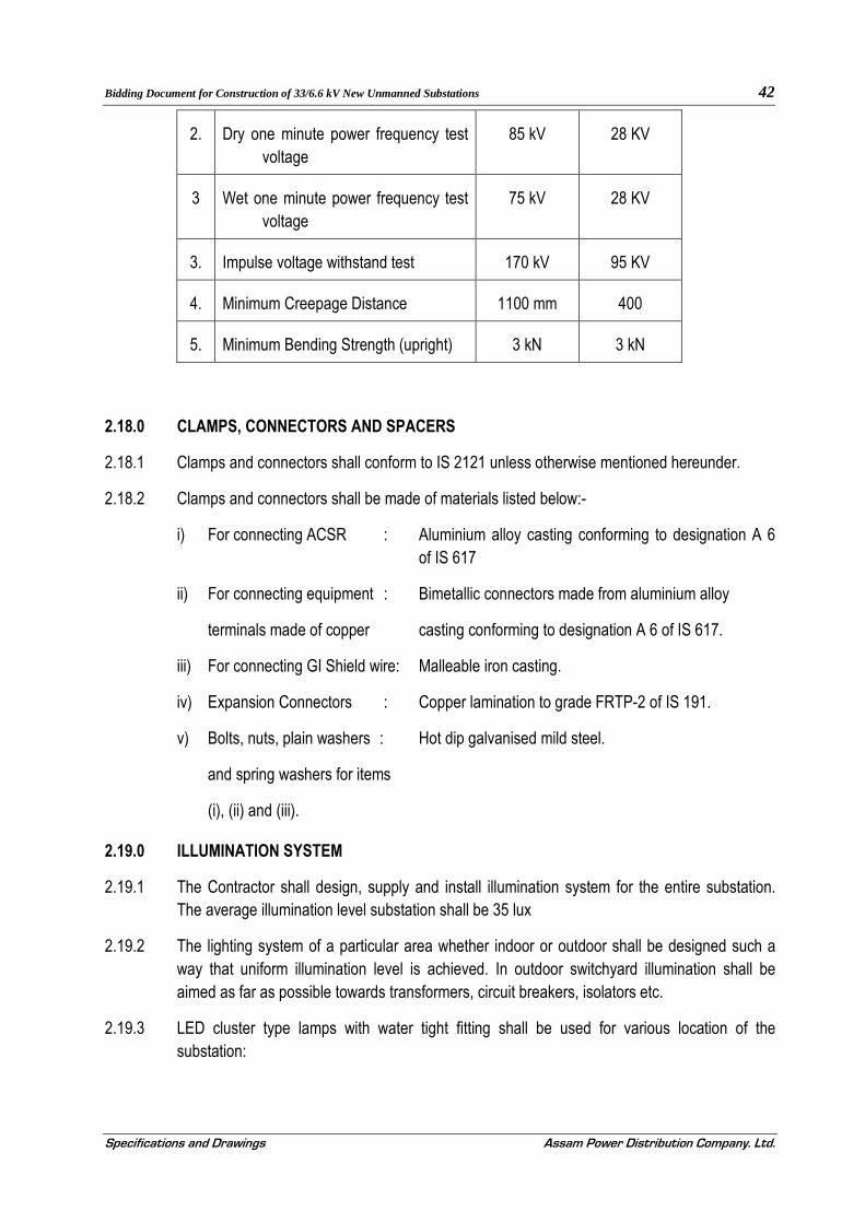
Bidding Document for Construction of 33/6.6 kV New Unmanned Substations 42
Specifications and Drawings Assam Power Distribution Company. Ltd.
2. Dry one minute power frequency test voltage
85 kV 28 KV
3 Wet one minute power frequency test voltage
75 kV 28 KV
3. Impulse voltage withstand test 170 kV 95 KV
4. Minimum Creepage Distance 1100 mm 400
5. Minimum Bending Strength (upright) 3 kN 3 kN
2.18.0 CLAMPS, CONNECTORS AND SPACERS
2.18.1 Clamps and connectors shall conform to IS 2121 unless otherwise mentioned hereunder.
2.18.2 Clamps and connectors shall be made of materials listed below:-
i) For connecting ACSR : Aluminium alloy casting conforming to designation A 6 of IS 617
ii) For connecting equipment : Bimetallic connectors made from aluminium alloy
terminals made of copper casting conforming to designation A 6 of IS 617.
iii) For connecting GI Shield wire: Malleable iron casting.
iv) Expansion Connectors : Copper lamination to grade FRTP-2 of IS 191.
v) Bolts, nuts, plain washers : Hot dip galvanised mild steel.
and spring washers for items
(i), (ii) and (iii).
2.19.0 ILLUMINATION SYSTEM
2.19.1 The Contractor shall design, supply and install illumination system for the entire substation. The average illumination level substation shall be 35 lux
2.19.2 The lighting system of a particular area whether indoor or outdoor shall be designed such a way that uniform illumination level is achieved. In outdoor switchyard illumination shall be aimed as far as possible towards transformers, circuit breakers, isolators etc.
2.19.3 LED cluster type lamps with water tight fitting shall be used for various location of the substation:

Bidding Document for Construction of 33/6.6 kV New Unmanned Substations 43
Specifications and Drawings Assam Power Distribution Company. Ltd.
2.19.4 Provisions shall be made in the switchyard steel structures for mounting of lamps for switchyard.
2.20.0 STATION SERVICE SUPPLY
2.20.1 A station service transformer of following ratings and specification shall be supplied complete with necessary LT and HT fuses for auxiliary ac power supply requirement of substation.
a. Type of cooling: ONAN
b. Normal Voltage Ratio: 33 kV / 0.433 kV
c. Rating: 100 kVA
d. Vector Group: Dy11
e. %age Impedance: 4.5%
Note: No negative tolerance is allowed.
f. Maximum allowable losses:
1. Maximum Losses at 50% loading : 560 Watts
2. Maximum Losses at 100% loading : 1820 Watts
Note: No positive tolerance is permissible. Losses found more than specified will be penalized as per prevailing practice of APDCL.
g. Winding material: Alluminium
h. Temperature rise limits:
(i). Rise of Winding Temperature above ambient: 45˚C
(ii). Rise of Oil Temperature above ambient: 40˚C
i. Maximum Flux Density at rated voltage at frequency: 1.6 tesla
j. Maximum current density: 1.4 Ampere/ sq. mm
2.21.0 FIRE FIGHTING EQUIPMENT
2.21.1 All the equipment in the switchyard shall be protected by portable fire extinguisher. These fire extinguishers are to be put at appropriate locations.
2.21.2 Relevant Indian Standards or equivalent shall govern the Portable fire extinguishers.
2.21.3 The fire fighting equipment shall consist of following:
(i). Carbon Dioxide type fire extinguishers (capacity 3 kg)- 2 nos.
(ii). Dry Chemical Powder (DCP) type fire extinguishers (capacity 5 kg) - 2 nos.
(iii). Fire Bucket with sand (9 liter) – 4 nos.

Bidding Document for Construction of 33/6.6 kV New Unmanned Substations 44
Specifications and Drawings Assam Power Distribution Company. Ltd.
(iv). Wheel / trolley mounted Dry Chemical Powder (DCP) type fire extinguishers (capacity 25 kg)- 1 nos.
2.21.4 Necessary fixtures/ covered stands / covered shade etc. shall also be provided for safekeeping of the above items.
2.22.0 Furniture & Fixture
2.22.1 Godrej make 4’ x 2.5’ table with drawer 1 no. Short back with coaster chair 3 (three) and standard computer table with key board rack 1 no. All the furniture shall be of Godrej make.
2.22.2 One 1KVA UPS with 2 hours power back-up of repute make.
2.23.0 SUBSTATION T & P
2.23.1 Following Tools & Plants of reputed make are in the scope of supply of the Contractor:
Sl No Item Description Unit Number
1 Chain Pully Block 2.5T capable of lifting up to ten feet No 1
2 Tirfur capable of pulling 2.5 Ton load No 1
3 Hand gloves (to operate 33KV) & Boots free size Set 2
4 Hook Stick (Folding type) resin bond No 1
5 Tool box
5.1 Pliers of various sizes – 6”, 8”, 12” Set 1
5.2 Insulated Screw drivers of various size – 6” to 18” Set 1
5.3 Wire Stripers – 6” No 2
5.4 Slide wrench – 12” & 18” Set 2
5.5 Nose Pliers – 6” No 2
5.6 Ratchet Spanner of various sizes (8 to 42 mm) Set 1
5.7 Box Spanner – Ring & D-Spanner (6 to 42 mm) Set 1
6.14 2.5 kV Insulation Tester No 1
6.15 Digital Multimeter No 1
6.16 Tongue Tester (Capable of measuring AC & DC current 1A to 500A and Voltage up to 700V, accuracy 0.5%)
No 1

Bidding Document for Construction of 33/6.6 kV New Unmanned Substations 45
Specifications and Drawings Assam Power Distribution Company. Ltd.
SECTION – 3
SPECIFICATION FOR DESIGN AND FEBRICATION
OF SUBSTATION STRUCTURES
3.1.0 SCOPE
3.1.1 This section covers the specification for galvanized steel tubular pole, channel cross arms,
bolts & nuts, other accessories etc for Substations covered under this Bid Document.
3.2.0 MATERIALS
3.2.1 Structural Steel
The structures shall be of structural steel conforming to any of the grade, as appropriate, of
IS 2062 (latest edition) Steel conforming IS 8500 may also be used.
Medium and high strength structural steels with known properties conforming to any other
national or international standards may also be used.
3.2.2 Bolts
Bolts used shall conform to IS12427 or bolts of property class 4.6 conforming to IS 6639 may
also be used.
High strength bolts, if used (only with steel conforming to IS 8500) shall conform to property
class 8.8 of IS 3757.
3.2.3 Nuts
Nuts shall conform to IS 1363 (Part 3). The mechanical properties shall conform to property
class 4 or 5 as the case may be as specified in IS 1367 (Part 6) except that the proof stress
for nuts of property class 5 shall be as given in IS 12427.
Nuts to be used with high strength bolts shall conform to IS 6623.
3.2.4 Washers
Washers shall conform to IS 2016. Heavy washers shall conform to IS 6610. Spring washers
shall conform to type B of IS 3663
Washers to be used with high strength bolts and nuts shall conform to IS 6649.
3.2.5 Galvanisation

Bidding Document for Construction of 33/6.6 kV New Unmanned Substations 46
Specifications and Drawings Assam Power Distribution Company. Ltd.
Steel tubular poles, Structural members, plain and heavy washers shall be galvanized in
accordance with the provisions of IS 4759.
Spring washers shall be hot dip galvanized as per service grade 4 of IS 4759 or IS 1537.
3.2.6 Other Materials
Other materials used in the construction of the supporting structures shall conform to
appropriate Indian Standards wherever available.
3.3.0 DESIGN PARAMETERS
3.3.1 The design shall be checked for following two loading conditions:
(A) Normal Conditions (all wires intact)
Under this condition, the loads shall be taken as under:
(i) Wire Tension:- Maximum Wire tension as specified in Clause 3.3.3.
(ii) Wind Load:- Loads due to 100% Design Wind Pressure (after accounting for drag
coefficient and gust factor) on structures, wires, insulators, equipment etc. Design
wind pressure shall be as per Clause 3.3.2.
(iii) Short Circuit Forces: Loading due to a 3 phase short circuit current of 25 kA shall
be considered for 33 kV subject to minimum of 10% of maximum wire tension as
considered in (i) above.
(B) Broken Wire Condition
Under this condition design shall be checked with all wires broken on one side and load
shall be as under:
(i) Wire Tension:- Wire tension for intact wires shall be taken as 100% of Clause 3.3.3
(A) (i). For broken wires it shall be taken as zero.
(ii) Wind Load:-Same wind load as calculated in Clause 3.3.3 (A) (ii) shall be
considered.
(iii) Short Circuit Forces:- Short circuit forces shall be considered only for intact wires.
(iv) Dead Weight: - Same dead load as calculated in Clause 3.3.3 (A) (iv) shall be
considered.
3.3.2 Design Wind Pressure

Bidding Document for Construction of 33/6.6 kV New Unmanned Substations 47
Specifications and Drawings Assam Power Distribution Company. Ltd.
The Design Wind pressure for the purpose of this Specification shall be taken as 793 N/m2.
This wind pressure corresponds to Terrain Category 2 and Reliability Level 1 as per IS 802
(Part 1/Section 1).
3.3.3 Wire Tensions
For design purpose tension in each power and shield wires shall be taken as under
a. For Power Conductors
(i) 33 kV switchyard. →6000 N for each Bus Bar conductor and other
jumpers/jack buses.
b. For Shield Wires
(i) 33 kV →6000 N for shield wire between Line gantry
→5000 N for shield wires at other Location.
Note: Structures with earth peak shall assume to have four earth wires for design
purpose in normal condition.
3.3.4 Spans
Following Spans shall be considered in design of all structures as applicable:-
a). Line gantries (structures to terminate lines):
(i) For 33 KV Switchyard: →5 Meter, wind & weight span.
b). All other Structures
(i) For 6.6 KV Switchyard: →4 Meter, wind & weight span.
3.3.5 Conductors and Shield Wires
if not otherwise specified in the drawings,A) Following sizes of power conductors shall be
used for design of structures:
a) For 33 kV switchyard:-
(i) ACSR ‘PANTHER’ conductor for Main Bus Bars and jumpers between two
segregated Main Bus Bars.

Bidding Document for Construction of 33/6.6 kV New Unmanned Substations 48
Specifications and Drawings Assam Power Distribution Company. Ltd.
B) For protection against direct lightning G.I. rod of minimum 25 mm shall be considered for
all switch yards.
3.4.0 DESIGN DRAWINGS
3.5.0 ACCESSORIES
3.5.1 Step Bolts
3.5.2 Insulator Strings and Conductor Clamps Attachments
(i) Earthwire Clamps Attachment
i. Suspension Clamp
The detailed drawing shall be submitted by the Contractor for Employer's approval. The
Contractor shall also supply U- bolts, D-shackles wherever required.
ii. Tension Clamps
Earth-wire peaks of tension towers shall be provided with suitable plates to
accommodate the shackle of tension clamps. The contractor shall also supply the U-bolts
wherever required and take Employer's approval for details of the attachments before the
mass fabrication.
3.6.0 FABRICATION
3.6.1 Erection mark
3.7.0 GALVANIZING AND PAINTING
3.7.1 Galvanising of the Pole and various members of the structures shall be done only after all
works of sawing, shearing, drilling, filing, bending and matching are completed. Galvanising
shall be done by the hot dip process as recommended in IS: 2629 or other such authoritative
international standards and shall produce a smooth, clean and uniform coating of not less
than 610 gm per square meter. The preparation for galvanising and the galvanising process
itself must not affect adversely the mechanical properties of the treated materials.
3.7.2 All assembly bolts shall be thoroughly hot dip galvanized after threading. Threads shall be of
a depth sufficient to allow for the galvanized coating, which must not be excessive at the root
of the threads, so that the nut shall turn easily on the completed bolts without excessive
looseness. The nut threads shall not be galvanized, but oiled only.
3.7.3 The outside surface shall be galvanised. Sample of galvanised materials shall be supplied to
the galvanising test set out in IS 729 or other such authoritative international standards.
3.8.0 EARTHING

Bidding Document for Construction of 33/6.6 kV New Unmanned Substations 49
Specifications and Drawings Assam Power Distribution Company. Ltd.
3.8.1 To keep provision in the Pole/structures for earthing, holes shall be drilled on two diagonally
opposite legs of the mounting structures. The holes shall be suitable for bolting 65 mm X 12
mm GI strips and shall be such that the lower hole is about 350 mm above the ground level,
clear of the concrete muffing, for connecting the earthing strip.
3.9.0 TEST AND TEST CERTIFICATE
3.9.1 Each consignment ready for transportation shall be offered to APDCL for inspection before dispatch giving a minimum time of not less than 15 days. Samples of fabricated structure materials shall be subjected to following tests: -
a. Steel: The structural steel shall conform to IS 226 and IS 8500, BS 4360-1068 or ISO / R 630 other such authoritative international standards. Manufacturer's test certificate shall be submitted for all used steel.
b. Galvanising: The galvanising shall be as per IS 2633 or BS 729 other such authoritative international standards. Zinc coating over the galvanised surfaces shall not be less than 610 gm per square meter.
c. Bolts and nuts: Manufacturer's test certificate as per standard practice shall be submitted.
3.9.2 Test at Contractor's Premises
3.9.2.1 GI Pole and structures shall be tested at fabricator works as per relevant IS. If any pole or structure is found to be weak or damaged the design should be suitably modified and shall have to re-tested.

Bidding Document for Construction of 33/6.6 kV New Unmanned Substations 50
Specifications and Drawings Assam Power Distribution Company. Ltd.
SECTION-4
TECHNICAL SPECIFICATION FOR
POWER TRANSFORMERS
4.1.0 SCOPE
4.1.1. These specifications are intended to cover design, engineering, manufacture, testing/inspection before dispatch, forwarding, packing, transportation to site, insurance (both during transit & storage), storage, erection, supervision, testing and commissioning of 33/6.6 kV Step-Down ONAN Transformers complete with all accessories/fittings and spare parts as specified herein.
4.2.0 BIDDING
4.2.1. Each Technical Proposal must be accompanied by each of the following information/ documents with sufficient details along with other documents and information mentioned elsewhere to enable the purchaser to make an appraisal of the quality and suitability of the material and equipment offered.
(a) Type test certificates of transformer of identical design from a NABL recognised laboratory, preferably at CPRI laboratory. The Type test certificates should not be more than 3 (three) years old. The type rest certificates should also be accompanied by the drawings of equipment tested so that the test certificates can be directly linked to the equipments offered. In this regard following points shall also be noted:
(i) Equipment which have not been type tested as above shall not be accepted. A promise or agreement by a bidder to have the equipment tested after award of a contract is not acceptable.
(b) Type Test reports to be acceptable must relate directly to the equipment offered. Type Test reports for a higher class/rating of equipment are acceptable with a commitment from bidder that the type test will be performed free of charge on the particular equipment after the award of contract.
(c) Guaranteed and Other Particulars in the formats given in SECTION-17 of this volume. The bid should also be accompanied by manufacturer’s literatures and brochures.
4.2.2. Failure to meet the requirement of this Clause 4.2.0 shall render a Bid non-responsive.
4.3.0 SPECIFIC TECHNICAL REQUIREMENTS (STANDARD CONDITIONS)
i. Rated MVA : 6.3/1.6
ii. Type of cooling : ONAN
iii. Number of Phases : Three
iv. Type of Installation : Outdoor
v. Frequency : 50 Hz.
vi. Cooling medium : Insulating Oil.
vii. Rated Voltage

Bidding Document for Construction of 33/6.6 kV New Unmanned Substations 51
Specifications and Drawings Assam Power Distribution Company. Ltd.
a) High Voltage Winding : DELTA
b) Low Voltage Winding : STAR
viii. Highest Continuous System Voltage:
a) High Voltage : 36 KV
b) Low Voltage : 7.2 KV
ix. Method of System Earthing :
a) High voltage : Unearthed
b) Low voltage : Solidly Grounded.
x. Type of tap changer : OFF LOAD
xi. Range of tapping : (+)3% to (-) 9% in steps of 3%
xii. Neutral terminal to be brought out : On LV Side only.
xiii. Impedance on rated MVA at 75° C : 1.6 MVA 6.3 MVA
(without (-) tolerance) 6.25%. 8.35%.
xiv. Type of Insulation and : 6.6 KV 33 KV
Insulation level
a) Type of insulation : Uniform
b) One min. PF withstand : 20KV 70KV
test voltage (KV-RMS)
c) Impulse withstand test : 60KV 170KV
Voltage (kvp)
xv. a) Winding connection : Delta(HV) Star (LV)
b) Material : Electrolytic Copper
xvi. Vector group : Dyn-11
xvii. Type of cooling : ONAN
xviii. Neutral Earthing : LV neutral shall be solidly earthed
through an
xix. Terminal Details
a) 33 KV Termination (outdoor) : ACSR WOLF conductor
xx. Outdoor Lightning Arrestor mounted on brackets.
b) 6.6 KV Termination : 1C-500 mm2 XLPE cable 2 nos. each
4.3.1. Maximum Temperature rise over an ambient of 50° C
a) Temperature rise of top oil = 40° C
(measured by Thermometer)
b) Temperature rise of winding = 45° C
(measured by resistance)
4.3.2. Maximum LOSS (without positive tolerance)
a) No-load loss : 2.0KW/5.4 KW
b) Load Loss at 750C : 14.0 KW/33.0 KW

Bidding Document for Construction of 33/6.6 kV New Unmanned Substations 52
Specifications and Drawings Assam Power Distribution Company. Ltd.
4.3.3. RATING & SERVICES
4.3.4. Over load capacity : As per IS: 6600
4.3.5. NOISE LEVEL AT RATED VOLTAGE & FREQUENCY : As per NEMA Pub TR-1.
4.3.6. MARSHALLING BOX:
One sheet steel (3.15mm size) weather proof marshaling box of suitable construction shall be
provided. Degree of Protection IP-55.
4.3.7. CAPITALIZATION OF LOSSES AND LIQUIDATED DAMAGES:
The capitalization of guaranteed losses of the transformer shall be calculated and considered while evaluating the bids. The guaranteed values of no load losses and load losses shall be stated in the bid. Liquidated damages will be applied to successful bidder for not achieving the quoted guaranteed figures (see clause 4.13.26)
4.4.0 PERFORMANCE:
i. Transformer shall be capable of withstanding for three seconds for 25 KA without
damage to any external short circuit, with the short circuit MVA available at the
terminals.
ii. The maximum flux density in any part of the core and yoke at normal voltage and
frequency shall be such that the flux density under 10% over voltage condition shall not
exceed 1.60 Tesla. With limiting value as (vi) below.
iii. Transformer shall under exceptional circumstances due to sudden disconnection of load,
be capable of operating at the voltage approximately 25% above normal rated voltage
for a period of not exceeding one minute and 40% above normal for a period of 5
seconds
iv. The Transformer may be operated continuously without danger on any particular
tapping at the rated MVA ±10% of the voltage corresponding to the tapping.
v. The thermal ability withstand short circuit shall be demonstrated by calculation.
vi. With combined voltage and frequency variation of +10%, the flux density shall not
exceed 1.7 Tesla.
4.5.0 AUXILIARY POWER SUPPLIES:
The following power supplies shall be available at site:
i) AC, 3-Phase, 400 Volts, 50 Hz. Earthed.
ii) AC, 1-Phase, 230 Volts, 50 Hz. Earthed.
iii) 48 V DC
4.6.0 DRAWINGS INCORPORATING THE FOLLOWING PARTICULARS SHALL BE SUBMITTED WITH THE BID:
(i) General outline drawing showing shipping dimensions and overall dimensions, net
weights and shipping weights, quality of insulating oil, spacing of wheels in either
direction of motion, location of coolers, marshalling box and tap changers etc.
(ii) Height of centre line of HV and LV connectors of transformers from the rail top level.
(iii) Dimensions of the largest part to be transported.
(iv) GA drawings/details of various types of bushing.

Bidding Document for Construction of 33/6.6 kV New Unmanned Substations 53
Specifications and Drawings Assam Power Distribution Company. Ltd.
(v) Type test certificates of similar transformers.
(vi) Illustrative & descriptive literature of the Transformer.
(vii) Maintenance and operation Instructions.
4.7.0 SPARE PARTS:
The mandatory spare parts shall include but not be limited to the following for each rating of
transformer.
(i) Bushings:
a. High Voltage - 1 No.
b. Low Voltage - 1 No.
c. Neutral Bushing - 1 No.
(ii) Complete set of gaskets for all - 1 Set
openings on the tank requiring gasket.
(iii) Magnetic oil level gauge with low oil - 1 No.
level alarm contacts.
(iv) Oil temperature indicator with alarm - 1 No.
and trip contacts and maximum reading pointer.
(v) Winding temperature indicator with alarm and trip - 1 No.
contacts and maximum reading pointer
(vi) Set of all types of valves comprising one in each type. - 1 Set
(vii) Silicagel breather - 1 No.
(viii) Buchholz Relay - 1 No.
Note: The quantities indicated above are for each transformers.
4.8.0 WARRANTY
4.8.1. The contractor shall be responsible to replace, free of the cost with no transportation and insurance expenses to the purchaser up to the destination of materials specified in schedule of dispatch, the whole or any part of the material which under normal and proper use and maintenance proves defective in material or workmanship within 12 months from the date of commissioning or 18 months from the date of dispatch whichever express earlier, provided the purchaser gives prompt written notice of such defects. Such replacement shall be effected by the contractor with a reasonable time actually required to do so. Contractor’s liability upon the expiration of the period mentioned above shall terminate.
4.8.2. The above provisions shall also actually apply to the material replaced by the contractor under this clause, in case, the same is again found to be defective within 12 months of its replacement/repair.
4.9.0 GUARANTEES
4.9.1. The contracting firm shall guarantee among other things the following:
a) Quality and strength of the material used. b) Adequate factors of safety for all parts of equipment to withstand the mechanical and on electrical
stresses developed therein. These will be stated in the tender. c) Suitability of the design and workmanship of the equipment for the conditions envisaged in the
specification. d) Efficiencies, Temperature rise and other performance data on equipment which shall be furnished
in the tender.
Bidding Document for Construction of 33/6.6 kV New Unmanned Substations 54
Specifications and Drawings Assam Power Distribution Company. Ltd.
4.9.2. The tenderer shall be responsible for replacing at site free of cost any part or parts of the equipment that may prove faulty or fail manufacturing defects on one or more of the reasons given in clause 4.9.1 stated above within 5 years commencing from the DATE OF COMMISSIONING.
4.9.3. In case of failure of the transformer, the supplier shall take back the faulty transformer from its plinth for repair at their own cost (or replace the transformer with a new transformer) and deliver, at their own cost, unload at the destination sub-station transformer plinth within 45 days, from the date of intimation of defects to the satisfaction of the owner, at free of cost. If the repair/replacement will not be completed within 45 days, then the supplier shall pay penalty @ 0.5% of the contract price for each calendar week of delay from the end of 45 days from the date of intimation of defects. Also, the Purchaser reserves the right for forfeiture of the total Composite Bank Guarantee and all the Securities, available with APDCL, in case the Supplier fails to pay the penalty by one month before the expiry of the guarantee period. Also, this will be taken as adverse in all future tenders.
4.9.4. The Contractor shall furnish copies of test certificates of materials used for manufacture and also the test certificates of the tests conducted on the equipment after manufacture. The contractor shall also furnish the test certificate of bought out components for approval by the purchaser.
4.10.0 MISCELLANEOUS
i. Padlocks along with duplicate keys as asked for various valves, marshalling box etc. shall be supplied by the contractor, wherever applicable.
ii. Foundation bolt for wheel locking devices of Transformer shall be supplied by the Contractor.
4.10.1. DELIVERY:
The equipment shall be delivered, for Destination.
4.10.2. CONFLICT IN CLAUSE:
In case of any conflict between the Specific Technical Requirements and General Technical Requirements the requirements indicated as Specific Technical Requirement shall prevail over the General Technical Requirements.
4.10.3. SERVICES AND EQUIPMENT:
The following is also in the Contractor’s scope of work for turnkey executions.
i. Design of soak pit, cable trenches and foundations for transformers and other ground mounted equipment.
ii. All civil works.
4.10.4. SCHEDULES:
All schedules annexed to the specification, shall be duly filled by the bidder separately.
4.10.5. ALTITUDE FACTOR:
If the equipment is to be installed in the hilly area, necessary correction factors as given in the Indian Standard for oil temperature rise, insulation level etc. shall be applied to the Standard Technical Parameters given above.
Bidding Document for Construction of 33/6.6 kV New Unmanned Substations 55
Specifications and Drawings Assam Power Distribution Company. Ltd.
4.11.0 NAME PLATE
The following plates or an approved combined plate shall be fixed to each transformer Tank at
an average height of 1500 mm above the ground level:-
(a) A rating plate bearing the data, specified in IEC60076 Part - I. This place shall also
include: -
(i) The short circuit current rating.
(ii) Time factor for each winding measured.
(iii) Measured no load current and no load losses at rated voltage and rated frequency.
(iv) Measured load losses at 75° C (Normal tap only).
(v) D.C. resistance of each winding at 75° C.
(b) A diagram plate showing in an approved manner, the internal connections and the voltage vector relationship of the several windings, in accordance with IEC 60076 Part-I with the transformer voltage ratio for each tap and, in addition, a plan view of the transformer giving the correct physical relationship of the terminals.
(c) A plate showing the location and function of all valves and air-release cocks or plugs.
(d) Diagram plate, indicating the oil levels in the conservators dependent on the oil temperature.
(f) Loading plan plate, showing transport dimensions and masses. This plate shall also warn the erection staff not to remove any cover, before filling the tank with oil to such a level where the windings are not exposed to the atmosphere. This shall be fixed directly on to the transformer tank and shall not be removed for transport.
(g) Identification plates, alpha-numerical number in an approved manner, for marshalling cabinets, breathers, valves, cocks, accessories etc. (minimum size: 110mm x 50mm) rigidly fastened by rivets on corrosion proof base plates. In addition, the function (description) of the related devices shall be clearly indicated on these plates. The alphanumerical numbers on the identification plates shall be of such a size as to be clearly legible from the floor level.
(h) Plates, showing all control, measuring and monitoring circuits and terminal blocks. These plates shall be rigidly fixed at the inner side of the hinged door of the concerned marshalling kiosk.
4.12.0 GENERAL TECHNICAL REQUIREMENTS
4.12.1. CODES & STANDARDS
i. The design, material, fabrication, manufacture, inspection, testing before dispatch, erection, testing, commissioning and performance of Power Transformers at site shall comply with all currently applicable statutory regulations and safety codes in the locality where the equipment will be installed. The equipment shall also conform to the latest applicable standards and codes of practice. Nothing in this specification shall be construed to relieve the contractor of this responsibility.

Bidding Document for Construction of 33/6.6 kV New Unmanned Substations 56
Specifications and Drawings Assam Power Distribution Company. Ltd.
ii. Transformers shall conform to the current applicable standards (IS & IEC) and codes of
practice as specified in clause no. 4.12.2.
4.12.2. The equipment, materials and service covered by this specification shall conform to the latest
applicable provision of the following standards:
IS:5 :Colour for ready mixed paints.
IS335 :New Insulating oil for Transformer, Switchgears.
IS:1271 : Classification of insulating materials for electrical
machinery and apparatus in relation to their stability in services.
IS:2026 (Part I to IV) : Power Transformer.
IS:2071 : Method of high voltage testing.
IS:2099 : High Voltage Porcelain Bushing.
IS: 2147 : Degree of protection
IS:2705 : Current Transformers.
IS:3202 : Code of practice for climate proofing of electrical
equipments.
IS:3347 : Dimensions for porcelain Transformer Bushings.
IS:3637 : Gas operated relays.
IS:3639 : Fittings and accessories for power transformers.
IS:5561 : Electric Power Connectors.
IS:6600/BS:CP1010 : guide for loading of oil immersed transformers.
IS:10028 : Code of practice for selection, installation and
maintenance of transformers, Part I, II and III.
C.B.I.P. Publication : Manual on transformers.
IEC 60076 (Part I –VIII) : Power Transformer
If the standard is not quoted for any item, it shall be presumed that the latest version of
Indian Standard shall be applicable to that item.
4.12.3. DRAWINGS:

Bidding Document for Construction of 33/6.6 kV New Unmanned Substations 57
Specifications and Drawings Assam Power Distribution Company. Ltd.
a) The contractor shall furnish, within fifteen days after issuing of letters Award, six copies
each of the following drawings/documents incorporating name of project and transformer
rating for approval.
i. Detailed overall general arrangement drawing showing front and side elevations and
plan of the transformer and all accessories including radiators and external features
with details of dimension, spacing of wheels in either direction of motion, net
weights and shipping weights, crane lift for untanking, size of lugs and eyes, bushing
lifting dimensions, clearances between HV and LV terminals and ground, quantity of
insulating oil etc.
ii. Foundation plan showing loading on each wheel and jacking points with respect to
centre line of transformer.
iii. GA drawing/details of bushing and terminal connectors.
iv. Name plate drawing with terminal marking and connection diagrams.
v. Wheel locking arrangement drawing.
vi. Transportation dimension drawings.
vii. Interconnection diagrams.
viii. Over fluxing withstand time characteristics of transformer.
ix. GA drawing of marshalling box.
x. Control scheme/wiring diagram of marshalling box.
xi. Technical leaflets of major components and fittings.
xii. As built drawing of schematic, wiring diagrams etc.
xiii. Setting of oil temperature indicator, winding temperature indicator.
xiv. Completed technical data sheets.
xv. HV/LV conductor bushing.
xvi. Bushing assembly.
xvii. Bi-metallic connector for connection to “Wolf”/PANTHER ACSR/AAAC
conductor/Flexible connectors
xviii. Radiator type assembly.
b) All drawings/documents, technical data sheets and test certificates/results/calculations
shall be furnished.
4.12.4. Any approval given to the detailed drawings by the purchaser shall not relieve the contractor
of the responsibility for correctness of the drawing and in the manufacture of the equipment.
The approval given by the purchaser shall be general with overall responsibility with
contractor.
4.12.5. SERVICE CONDITIONS
The equipment has to be designed to suit the following climatic conditions
i. Maximum temperature of air in shade : 40° C
ii. Minimum temperature of air in shade : 2° C
iii. Maximum temperature of air in sun : 45 ° C
iv. Maximum humidity : 99%
v. Average number of thunder storm days per annum: 45 days.
vi. Maximum rainfall per annum : 3500 mm
vii. Average rainfall per annum : 2280 mm
viii. Wind pressure : 97.8 Kg/M²

Bidding Document for Construction of 33/6.6 kV New Unmanned Substations 58
Specifications and Drawings Assam Power Distribution Company. Ltd.
ix. Altitude above MSL : 100 M to 1000 M
4.12.6. GUARANTEE FOR TECHNICAL LOSSES
The bidder shall indicate values of no load losses at rated voltage and frequency at normal tap, load losses and auxiliary losses at rated output, voltage and frequency at normal tap. The bidder shall indicate maximum firm losses without tolerance. The no load loss value and no-load current at (-) 90%, (+) 112.5% and 100% of rated voltage and frequency. The load loss values shall also be furnished for operation at rated frequency and +3% and -9% and taps in addition to normal taps. The bidder is to submit the Annexure- II as per the enclosed format and failing of same will be treated as non-responsive.
4.13.0 DESIGN, STANDARDIZATION AND GENERAL CONSTRUCTION FEATURES.
i. All material used shall be best quality and of the class most suitable for working under the
conditions specified and shall withstand the variations of temperature and atmospheric
conditions without distortion or deterioration or the setting up of undue stresses which
may impair suitability of the various parts for the work which they have to perform.
ii. Similar parts, particularly removable ones , shall be interchangeable.
iii. Pipes and pipe fittings, screws, studs, nuts and bolts used for external connections shall be
as per the relevant standards. Steel bolts and nuts exposed to atmosphere shall be of hot
deep galvanized.
iv. Nuts, bolts and pins used inside the transformers and tap changer compartments shall be
provided with lock washers or locknuts.
v. Exposed parts shall not have pockets where water can collect.
vi. Internal design of transformer shall ensure that air is not trapped in any location.
vii. Material in contact with oil shall be such as not to contribute to the formation of acid in
oil. Surface in contact with oil shall not be galvanized or cadmium plated.
viii. Labels, indelibly marked shall be provided for all identifiable accessories like relays,
switches, current transformers etc. All label plates shall be of in corrodible material.
ix. All internal connections and fastening shall be capable of operating under overloads and
over-excitation, allowed as per specified standard without injury.
x. Transformers and accessories shall be designed to facilitate proper operation, inspection,
maintenance and repairs.
xi. No patching, plugging, shimming or other, such means of overcoming defects,
discrepancies or errors will be accepted.
xii. Schematic Drawing of the wiring, including external cables shall be put under the prospane
sheet on the inside door of the transformer marshalling box.
4.13.1. CLEANING & PAINTING
i. The Painting details are given as follows:
Description Surface preparation
Primer coat Finish coat Dry Flim Thickness
Colour Shade
Main tank, pipes, conservator, oil storage tank etc. (External
Shot Blast cleaning Sa 21/2 (ISO
Epoxy base zinc primer (60µm)
Aliphatic Polyurethane 2 coats (25
Minimum 110 µm
Shade No. RAL 7032

Bidding Document for Construction of 33/6.6 kV New Unmanned Substations 59
Specifications and Drawings Assam Power Distribution Company. Ltd.
surface) 8501-1) µm/coat)
Main tank, pipes, conservator, oil storage tank etc. (Internal surface)
Shot Blast cleaning Sa 21/2 (ISO 8501-1)
Hot oil resistant, non-corrosive varnish or paint or epoxy
- Minimum 30 µm
Glossy white for paint
Radiator (External surface)
Chemical/Shot Blast cleaning Sa 21/2 (ISO 8501-1)
Hot dip galvanized to IS: 2633.
Polyurethane 2 coats (25 µm/coat)
Minimum 110 µm
Matching shade of tank/different shade aesthetical
ii. Metal parts not accessible for painting shall be made of corrosion resistant materials. iii. Interior surfaces of mechanism chambers and marshalling kiosks shall receive three coats of paint
after proper cleaning. The final coat shall be of light coloured anti-corrosion paint. iv. All paints shall be carefully selected to withstand heat, rain and extreme of weather. The paint shall
not scale off or crinkle or be removed by abrasion due to normal handling. v. In case finish paint chips off or crinkle during transit or installation, the contractor shall arrange for
repainting transformer at site at his cost. The paint for repainting shall be supplied by the contractor. vi. The paint used shall be ISI marked. vii. The paint work done shall be guaranteed for a minimum period of 5 years from the date of receipt of
the equipment. viii. One coat of additional paint shall be given at site by the purchaser. Supplier shall supply the requisite
of paint.
4.13.2. DETAILED DESCRIPTION:
a) Tank
i. The Transformer tank and cover shall be fabricated from high grade low carbon plate steel of tested quality. The tank and the cover shall be of welded construction.
ii. Tank shall be designed to permit lifting by crane or jacks of the complete transformer assembly filled with oil. Suitable lugs and bosses shall be provided for this purpose.
iii. All beams, flanges, lifting lugs, braces and permanent parts attached to the tank, shall be welded and where practicable, they shall be double welded.
iv. The main tank body of the transformer, excluding tap changing compartments and radiators, shall be capable of withstanding pressure of 760 mm of Hg.
v. Inspection hole(s) with welded flange(s) and bolted cover(s) shall be provided on the tank cover. The inspection hole(s) shall be of sufficient size to afford easy access to the lower ends of the bushings, terminals etc.
vi. All connections, bolted to the tank shall be fitted with suitable gas oil resistant gaskets, made of such a material that no serious deterioration occurs under service conditions. Gaskets of nitrile rubber or equivalent shall be used to ensure perfect oil tightness. All gaskets shall be of closed design (without open ends) and shall be of one piece only. Rubber gaskets, used for flange connections of the various oil compartments shall be laid in grooves or in groove-equivalent retainers on both sides of the gaskets throughout their total length. Care shall be taken to secure uniformly distributed mechanical pressure over the gaskets and retainers throughout the total length. Gaskets of
neoprene and/or any kind of impregnated/ bonded cork or cork only which can easily be

Bidding Document for Construction of 33/6.6 kV New Unmanned Substations 60
Specifications and Drawings Assam Power Distribution Company. Ltd.
damaged by over-pressing are not acceptable. Use of hemp as gasket material is also not
acceptable.
vii. Suitable guides shall be provided for positioning the various parts during assembly or dismantling . Adequate space shall be provided between the cores and windings and the bottom of the tank for collection of any sediment.
b) Tank Cover.
The transformer top shall be provided with a detachable tank cover with bolted flanged gasket joint. The gasket should be of nitrile rubber. Lifting lugs shall be provided for removing the cover. The surface of the cover shall be suitable sloped so that it does not retain rain water.
Each tank cover shall be of adequate strength and shall not distort when lifted. Inspection opening shall be provided as necessary to give easy access to bushing, for changing ratio of winding connections or testing the earth connections. Each inspection opening shall be of ample size for the purpose for which it is provided, and at least two openings are at each end of the tank. The tank cover and inspection cover shall be provided with suitable lifting arrangements. The tank cover shall be fitted with pockets for thermometer and for the bulbs of the oil and winding temperature indicators and same should be placed at the center of the top cover.
The thermometer pockets shall be fitted with a captive screw cap to prevent the ingress of water.
4.13.3. UNDER CARRIAGE
i. The transformer tank shall be supported on steel structure with detachable forged steel flanged wheels suitable for moving the transformer completely filled with oil. Rail gauge shall be 1462+0 mm in both directions. Flanged wheels shall be spaced accordingly. Wheels shall be provided with suitable bearings which will resist rust and corrosion and shall be equipped with fittings for lubrication. It shall be possible to swivel the wheels in two directions, at right angle to or parallel to the main axis of the transformers.
ii. Jacking pads shall be provided on the transformer. It shall be possible to change the direction of the wheels through 90° when the transformer is lifted on jacks to permit movement of the transformer both in longitudinal and transverse directions.
iii. Suitable hydraulic jacks (4 nos.) for lifting the transformer shall be supplied by the contractor, for each rating of the transformer.
4.13.4. CORE (MAGNETIC CIRCUIT)
i. The magnetic circuit shall be constructed from high grade cold rolled non-ageing grain oriented silicon steel lamination of M-4 grade or better and thickness should not be more than 0.27 mm.
ii. The primary core material is only to be used. The bidder should offer the core for inspection and approval by the purchaser or third party Inspection Agency during the manufacturing stage. Bidder’s call notice for the purpose should be accompanied with the following document as applicable as a proof towards use of Prime Core material.
(a) Invoice of supplier,
(b) Mill’s test certificate.
(c) Packing list,
(d) Bill of loading,
(e) Bill of entry certificate to custom

Bidding Document for Construction of 33/6.6 kV New Unmanned Substations 61
Specifications and Drawings Assam Power Distribution Company. Ltd.
Core material should be directly procured from either the manufacturer or their accredited
marketing organisation of repute and not through any agent.
iii. The transformer shall be designed in such a way that the maximum flux density in any part
of the core and yoke at rated M.V.A, minimum frequency (48.5HZ) and highest system
voltage shall not exceed 1.6 Tesla. The tenderer shall establish this by calculation as per
given format (Annexure-I).
iv. The laminations shall be free of all burns and sharp projections. Each sheet shall have an
insulating coating resistant to the action of hot oil.
v. Core should be of BOLTLESS type.
vi. The insulation structure for the core to bolts and core to clamp plates, shall be such as to
withstand a voltage of 2000 V for one minute.
vii. The completed core and coil shall be so assembled that the axis and the plane of the outer
surface of the core stack shall not deviate from the vertical plane by more than 25 mm.
viii. All steel sections used for supporting the core shall be thoroughly shot or sand blasted,
after cutting, drilling and welding.
ix. The finally assembled core with all the clamping structures shall be free from deformation
and shall not vibrate during operation.
x. The core clamping structure shall be designed to minimize eddy current loss.
xi. The framework and clamping arrangements shall be securely earthed.
xii. The core shall be carefully assembled and rigidly clamped to ensure adequate strength.
xiii. Oil ducts shall be provided where necessary to ensure adequate cooling. The welding
structure and major insulation shall not obstruct the free flow of oil through such ducts.
xiv. The design of magnetic circuit shall be such as to avoid static discharges, development of
short circuit paths within itself or to the earthed clamping structure and production of flux
component at right angle to the plane of the lamination which may cause local heating.
The supporting framework of the cores shall be so designed as to avoid the presence of
pockets which would prevent complete emptying of the tank through the drain valve or
cause trapping of air during filling.
xv. The construction is to be of ‘core’ type. The core shall be provided with lugs suitable for
lifting the complete core and coil assembly. The core and coil assembly shall be so fixed in
the tank that shifting will not occur during transport or short circuits.
4.13.5. MAGNETIC CIRCUIT
4.13.5.1. The design of the magnetic circuit shall be such as to avoid static discharges, development of short circuit paths within itself or to the earthed clamping structure and the production of flux compartments at right angles to the plane of the lamination which may cause local heating.
4.13.5.2. Every care shall be exercised in the selection, treatment and handling of core steel to ensure that as far as is practicable, the lamination are flat and the finally assembled core is free from distortion.
4.13.5.3. The oxide/silicate coating given on the core shall be adequate, however, laminations can be insulated by the manufacturers If considered necessary.
4.13.5.4. Oil ducts shall be provided where necessary to ensure adequate cooling. The winding structure and major insulation shall not obstruct the free flow of oil through such ducts.

Bidding Document for Construction of 33/6.6 kV New Unmanned Substations 62
Specifications and Drawings Assam Power Distribution Company. Ltd.
4.13.6. MECHANICAL CONSTRUCTION OF CORES
4.13.6.1. All parts of the core shall be of robust design of withstanding any shocks to which they may be subjected during lifting, transport, installation and service.
4.13.6.2. All steel sections used for supporting the core shall be thoroughly sand blasted or shot blasted after cutting, drilling and welding.
4.13.6.3. Any non-magnetic or high resistance alloy shall be of established quality.
4.13.6.4. Adequate lifting lugs shall be provided to enable the core and windings to be lifted.
4.13.6.5. Adequate provision shall be made to prevent movement of the core and winding relative to the tank during transport and installation or while in service.
4.13.6.6. The supporting framework of the copper shade be so designed as to avoid the presence of pockets which would prevent complete emptying of the tank through the drain valve, or cause trapping of air during failing.
4.13.7. INTERNAL EARTHING
4.13.7.1. EARTHING OF CORE CLAMPING STRUCTURE
i. All internal metal parts of the transformer, with the exception of individual laminations, core bolts and their individual clamping plates shall be earthed.
ii. The top clamping structure shall be connected to the tank by a copper strap. The bottom clamping structure shall be earthed by one or more of the following methods: a. By connection through vertical tie-rod to the top structure. b. By direct metal to metal contact with the tank base. c. By connection to the top structure on the same side of the core as the main earth
connection to the tank.
4.13.7.2. EARTHING OF MAGNETIC CIRCUIT.
i. The magnetic circuit shall be connected to the clamping structure at one point only and this shall be brought out of the top cover of the transformer tank through a suitably rated insulator. A disconnecting link shall be provided on transformer tank to facilitate disconnections from ground for IR measurement purpose.
ii. Core clamping rings of metal at earth potential shall be connected to the adjacent core clamping structure on the same side as the main earth connections.
4.13.7.3. SIZE OF EARTHING CONNECTIONS
i. All earthing connections with the exception of those from the individual coil clamping rings, shall have a cross-sectional area of not less 0.2 Sq. cm.
4.13.8. WINDING
i. All windings shall be made of electrolytic high conductivity copper shall be fully insulated as defined in IS:2026. All neutral points shall be insulated for the voltage specified in IS:2026. The winding shall be so designed that all coil assemblies of identical voltage, rating shall be interchangeable.
ii. Current density shall not exceed 2.5A/mm2. for HV and LV winding.
iii. Power transformers shall be designed to withstand the impulse test voltages as per IS:2026.

Bidding Document for Construction of 33/6.6 kV New Unmanned Substations 63
Specifications and Drawings Assam Power Distribution Company. Ltd.
iv. The transformer shall withstand the power frequency voltage test as per IS:2026.
v. The winding shall be designed to reduce to a minimum the out-of-balance forces in the transformers at all voltage ratios.
vi. The insulation of transformer winding and connection shall be free from insulating composition leading to soften Ooze out shrink or collapse during service.
vii. The stacks of windings shall receive adequate shrinkage treatment before final assembly.
viii. The coil clamping arrangement and the finished dimensions of any oil ducts shall be such as will not impede the free circulation of oil through the ducts.
ix. The conductors shall be transposed at sufficient intervals in order to minimize eddy current and equalize the distribution of currents and temperature along the windings.
4.13.9. BRACING OF WINDINGS.
i. The windings and connections of all transformers shall be braced to withstand shocks, which may occur during transport or due to switching and other transient condition during service.
ii. Coil clamping rings, if provided shall be of steel.
iii. Any metal pieces in contact with laminated rings shall be designed and secured that they do not weaken the electrical or the mechanical properties of the wings.
iv. If the transpose winding is built up of section of disc coils, separated by spacers, the clamping arrangements shall be such that equal pressures are applied to all columns of spacers. All such spacers shall be securely located, shall be of suitable material and shall receive adequate shrinkage treatment before assembly.
v. Winding shall be subjected to a shrinking and seasoning process, so that no further shrinkage occurs during service. Adjustable devices shall be provided for taking up possible shrinkage in service.
vi. All low voltage windings for use in the circular coil concentric winding shall be wound on a performed insulating cylinder for mechanical protection of the winding in handling and placing around the core.
vii. Winding shall not contain sharp bends which might damage the insulation or produce high dielectric stresses. No strip conductor wound on edge shall have width exceeding six times the thickness.
viii. Materials used in the insulation and assembly of the windings shall be insoluble, non-catalytic and chemically inactive in the hot transformer oil and shall not soften or the otherwise affected under the operating conditions.
ix. Varnish application on coil windings may be given only for mechanical protection and not for improvement in dielectric properties. In no case varnish or other adhesive be used which will seal the coil and prevent evacuation of air and moisture and impregnation by oil.
x. Winding and connections shall be braced to withstand shocks during transport or short circuit.
xi. Permanent current carrying joints in the windings and leads shall be through cold crimping. Clamping bolts for current carrying parts inside oil shall be made of oil resistant material which shall not be affected by acidity in the oil steel bolts, if used, shall be suitable treated.
xii. Terminals of all windings shall be brought out of the tank through bushings for external connections.
xiii. The completed core and coil assembly shall be dried in vacuum at not more than 0.5 mm of mercury absolute pressure and shall be immediately impregnated with oil after drying process to

Bidding Document for Construction of 33/6.6 kV New Unmanned Substations 64
Specifications and Drawings Assam Power Distribution Company. Ltd.
ensure the elimination of air and moisture within the insulation. Vacuum may be applied in either vacuum cover or in the transformer tank.
xiv. The winding shall be so designed that all coil assemblies of identical voltage ratings shall be interchangeable and field repairs to the winding can be made readily without special equipment. The coils shall have high dielectric strength.
xv. Coils shall be made of continuous smooth high grade electrolytic copper conductor, shaped and braced to provide for expansion and contraction due to temperature changes.
xvi. Adequate barriers shall be provided between coils and core and between high and low voltage coil. End turns shall have additional protection against abnormal line disturbances.
xvii. Tapping’s shall not be brought out from inside the coil or from intermediate turns and shall be so arranged as to preserve as far as possible magnetic balance of the transformer at all voltage ratios.
4.13.10. INSULATING OIL.
i. The insulating oil for the transformer shall be of EHV grade, generally conforming to IS:335. No inhibitors shall be used in the oil.
ii. The quantity of oil required for the first filling of the transformer and its full specification shall be stated in the bid. The bidder shall quote the price of transformer complete with first filling of oil plus 10% extra. However, the rate of transformer oil in Rupee per litre shall be quoted separately also. The transformer oil shall be supplied in non returnable drums.
iii. The design and materials used in the construction of the transformer shall be such as to reduce the risk of the development of acidity in the oil.
iv. The contractor shall warrant that oil furnished is in accordance with the following specifications.
Sl.N
o
Characteristic Requirement Method of Test
1. Appearance
The oil shall be clear and
transparent and free
from suspended matter
or sediment
A representative
sample of oil shall
be examined in a
100 mm thick
layer at ambient
temp.
2. Density at 20° C Max 0.89 g/cm² IS:1448
3. Kinetic Viscosity at 27° C Max 27 CST IS:1448
4. Interfacial at 27° C Min 0.03 N/m IS:6104
5. Flesh Point 140° C IS:1448
6. Pour Point Max. -6° C IS:1448
7. Neutralization Value (Total
Acidity) Max
0.03 mg/KOH/g IS:335

Bidding Document for Construction of 33/6.6 kV New Unmanned Substations 65
Specifications and Drawings Assam Power Distribution Company. Ltd.
Sl.N
o
Characteristic Requirement Method of Test
8. Electric Strength (Breakdown
Voltage) Min
a. Less than 72.5 KV 40 KV Class
b. 725.5 KV Class 50 KV
9. Dielectric dissipation factor tanδ
at 90° C Max.
0.05 IS:6262
10. Min. specific resistance
(resistivity) at 90° C
1 X 10¹² ohm cm IS:6013
11. Oxidation stability
a. Neutralization value
after max.
b. Total sludge after
oxidation
0.40 mg/KOH/g
0.10% by weight
12. Presence of oxidation inhibitor The oil shall not contain
anti-oxidant Additives
IS:335
13. Water content Max.
a. Less than 72.5 KV Class
25 ppm
IS:2362
4.13.11. COOLING
For the cooling of transformers of ONAN type, the transformers shall be equipped with natural oil circulation type for the transformer. The transformers shall be capable of giving a continuous output without exceeding the specified temperature rise at least equal to that stated in schedule of requirements with all the artificial cooling out of service.
4.13.12. RADIATORS & VALVES
4.13.12.1. RADIATORS
i. Radiators shall be designed so that all painted surface can be thoroughly cleaned by hand and subsequently.
ii. Radiators shall be designed so as to avoid pockets in which moisture collects and shall withstand the pressure tests. Radiators shall be detachable and shall be provided with machinated or ground flanged inlet and outlet branches. Air release plug shall be provided at the top of each radiator for draining and filling.
4.13.12.2. VALVES
i. Valves shall be of forged carbon steel upto 50 mm size and of gun metal or of cast iron bodies with gun metal fittings for sizes above 50 mm. They shall be of full way type with screwed ends

Bidding Document for Construction of 33/6.6 kV New Unmanned Substations 66
Specifications and Drawings Assam Power Distribution Company. Ltd.
and shall be opened by turning counter clock wise when facing the hand wheel. There shall be no oil leakage when the valves are in closed position.
ii. Each valve shall be provided with an indicator to show the open and closed position and shall be provided with facility for padlocking in either open or closed position. All screwed valves shall be furnished with pipe plugs for protection. Padlocks with duplicate keys shall be supplied along with the valves.
iii. All valves except screwed valves shall be provided with flanges having machined faces drilled to suit the applicable requirements. Oil tight blanking plates shall be provided for each connection for use when any radiator is detached and for all valves opening to atmosphere. If any special radiator valve tools are required, the Contractor shall supply the same.
iv. Each transformer shall be provided with following valves on the tank
a. Drain valve so located as to completely drain the tank. b. Two filter valves on diagonally opposite corners, of 50 mm size. c. Oil sampling valves not less than 8 mm at top and bottom of main tank d. One 15 mm air release plug. e. Valves between radiators and tank. f. Valve prior to and after the Buchholz Relay. g. Sludge removal valve at bottom 15 mm.
Drain and filter valves shall be suitable for applying vacuum as specified in the specifications.
4.13.13. ACCESSORIES & FITTINGS
4.13.13.1. BUSHINGS
Bushings for 36 KV and below shall be of solid porcelain type. These bushings shall be suitable for bare ACSR conductor connections/ Flexible connectors.
All bushings shall be equipped with suitable terminals of approved type and size and all external current carrying contact shall be adequate silver plate. All ends as well as tops of the coil shall be brought to terminals. In case of connections required outside the tank, these shall be brought out to their respective terminals through well insulated bushings which shall be detachable and replaceable without disturbing internal connections. Bushings which pass through the cover shall be removable without disturbing the transformer cover.
i. The bushing shall have sufficient insulation to avoid leakage to ground and shall be so located as to provide adequate electrical clearance between bushing or various voltages and between bushiness and grounded parts. The insulation class of the high voltages neutral bushing shall be properly co-ordinated with the insulation class of the neutral of the high voltage winding.
ii. Stresses due to expansion and contraction in any part of the bushing insulator shall not lead to the development of defects. Outdoor insulators and fittings shall be unaffected by atmospheric conditions due to weather, fuses, ozone, acids, dust and rapid changes of air temperature. Any stress shield shall be considered as integral part of the bushing assembly.
iii. Porcelain shall not engage directly with hard metal and where necessary gaskets shall be interposed between the porcelain and the fittings. All porcelain clamping surface in contact with gasket shall be accurately grounded and free from glaze
iv. Fixing material used shall be of suitable quality and properly applied and shall not enter into chemical action with the metal parts or cause fracture by contraction expansion in service. Cement thickness shall be as small and even as possible and proper care shall be taken to centre and locate individual parts correctly during cementing. All porcelain insulators shall be designed to facilitate clearance.

Bidding Document for Construction of 33/6.6 kV New Unmanned Substations 67
Specifications and Drawings Assam Power Distribution Company. Ltd.
v. Each porcelain bushing or insulator, and paper bushing shall have marked upon it the manufacturer’s identification mark, and such other marks as may be required to assist in the representative selection of batches for the purpose of the sample tests.
vi. Clamps and fittings made of steel or galvanized. The bushing flanges shall not be re-entrant type (shape) which may trap air.
vii. Each bushing shall be so coordinated with the transformer insulation, that the flashover will occur outside the tank.
viii. All porcelain used in bushings shall be of wet process, homogeneous and free from cavities or other flaws. The glazing shall be uniform in colour (brown) and free from blisters, burns and other defects. Porcelain shall be thoroughly vitrified and shall be impervious to moisture.
ix. All bushing shall have puncture strength greater than dry flashover value.
x. Creepage distance will be kept 27 mm/KV. Bushings may be provided with weather shield.
xi. The tenderer is requested to give the guarantee withstand voltage for the above and also furnish a calibration curve with different settings of the co-ordination gap to enable the purchaser to decide the actual gap settings. Tenderer’s recommendations are also invited to this respect. During spark gap flashover, the arc shall remain away from the housing insulator.
xii. Each terminal (including neutral) shall be distinctly marked and coloured for phase voltage and phase rotation on the primary secondary and tertiary sides in accordance with the diagram of connection supplied with the transformer, the system of marking shall conform IS 2026-1962 amended upto date.
xiii. All porcelain used in bushings shall be homogeneous, non-porous, uniformly glazed to brown colour and free from blisters, burns and other defects.
xiv. Stress due to expansion and contraction in any part of the bushing shall not lead to deterioration.
xv. Bushing shall be designed and tested to comply with the applicable standards.
xvi. Bushings rated for 400A and above shall have non-ferrous flanges and hardware.
xvii. Fittings made of steel or malleable iron shall be galvanized.
xviii. Bushing shall be so located on the transformer that full flashover strength will be utilized. Minimum clearances as required for the BIL shall be realized between live parts and live parts to earthed structures.
xix. All applicable routine and type tests certificates of the bushings shall be furnished for approval.
xx. Bushings shall be supplied with bimetallic/terminal connectors/ clamp suitable for fixing to bushing terminal and the PURCHASER’S specified conductors. The connectors/clamp shall be rated to carry the bushing rated current without exceeding a temperature rise of 55° C over an ambient of 40° C. the connector/ clamp shall be designed to be corona free at the maximum rated line to ground voltage.
xxi. Bushing of identical voltage rating shall be interchangeable.
xxii. Each bushing shall be so coordinated with the transformer insulation that all flashover will occur outside tank.
4.13.14. PROTECTION & MEASURING DEVICES.
4.13.14.1. On the Conservator Tank

Bidding Document for Construction of 33/6.6 kV New Unmanned Substations 68
Specifications and Drawings Assam Power Distribution Company. Ltd.
a. The conservator tank shall have adequate capacity between highest and lowest visible levels to meet the requirement of expansion of the total cold oil volume in the transformer and cooling equipments.
b. The conservator tank shall be bolted into position so that it can be removed for cleaning purposes.
c. The conservator tank shall be fitted with magnetic oil level gauge with low level electrically insulated alarm contact.
d. The conservator tank shall be fitted with flexible diaphragm type.
e. Transformer shall be provided with thermo siphon filters for ratings of 6.3 MVA to prolong the life of the transformer oil. The minimum capacity should be of 2% of total oil volume of the transformer.
f. The conservator should have “Air Cell”.
4.13.14.2. Pressure Relief Device.
i. The pressure relief device provided shall be of sufficient size for rapid release of any
pressure that may be generated in the tank and which may result in damage of the
equipment. The device shall operate at a static pressure of less than the hydraulic
test pressure of transformer tank. It shall be mounted direct on the tank. A pair of
electrically insulated contacts shall be provided.
ii. Unless otherwise approved the relief device shall be mounted on the main tank, and
if on the cover shall be fitted with skirt projecting 25 mm inside the tank and of such
a design to prevent gas accumulation.
4.13.14.3. Buchholz Relay
A double float type Buchholz Relay shall be provided. Size should not be less than 50 mm for 1.6 MVA and 80 mm for 6.3 MVA. Any gas evolved in the transformer shall collect in this relay. The relay shall be provided with a test cock suitable for a flexible pipe connection for checking its operation. A copper tube shall be connected from the gas collector to a valve located about 1200 mm above ground level to facilitate sampling with the transformer in service. The device shall be provided with two electrically independent ungrounded contacts, one for alarm on gas accumulation and the other for tripping on sudden rise of pressure.
4.13.14.4. Temperature Indicator.
a. Oil Temperature Indicator (OTI)
The transformers shall be provided with a 150 mm dial type thermometer for top oil temperature indication. The thermometer shall have adjustable, electrically independent ungrounded alarm and trip contacts preferably of mercury. Number of mercury contacts should be minimum of four pairs. Maximum reading pointer and resetting device shall be mounted in the local control panel. A temperature sensing element suitably located in a pocket on top oil shall be furnished. This shall be connected to the OTI by means of capillary tubing. Accuracy class of OTI shall be ±1% or better.
b. Winding Temperature Indicator (WTI)
A device for measuring the hot spot temperature of the winding shall be provided. It shall comprise the following.

Bidding Document for Construction of 33/6.6 kV New Unmanned Substations 69
Specifications and Drawings Assam Power Distribution Company. Ltd.
i. Temperature sensing element.
ii. Image Coil.
iii. Auxiliary CTS, if required to match the image coil, shall be furnished and mounted
in the local control panel.
iv. 150 mm dial local indicating instrument with maximum reading pointer mounted
in local panel and with adjustable electrically independent ungrounded contacts,
besides that required for control of cooling equipment, one for high winding
temperature alarm and one for trip. It should have at least four pairs of mercury
contacts.
v. Calibration device.
vi. Accuracy class of WTI shall be ±1% or better.
4.13.14.5. Oil Preservation Equipment.
Oil Sealing
The oil preservation shall be diaphragm type (Air cell) oil sealing in conservator to prevent oxidation and contamination of oil due to contact with atmospheric moisture.
4.13.14.6. Breather
Each conservator vessel shall be fitted with a breather in which silicagel is the dehydrating agent and designed so that:
a. The passage of air is through the silicagel.
b. Silicagel is isolated from atmosphere by an oil seal
c. The external atmosphere is not continuously in contact with the silicagel.
d. The moisture absorption indicated by a change in colour of the tinted crystal can be easily observed from a distance.
e. All breathers shall be mounted approximately 1200 mm above the ground level.
f. Quantity of Silicagel should be of minimum 1Kg for 2000 lt of oil.
4.13.14.7. Thermo-siphon Filter:
Thermo-syphon filter shall be fitted for 6.3 MVA rating or above capacity of transformers. To extract the harmful constituents like water, acid etc. from oil, thermo siphon filter of cylindrical shape with perforated steel trays filled with absorbents such as active alumina should be provided.
The filter assembly shall be mounted on the transformer as well as ground supported and connected with pipes and shut off valves. Suitable instructions required to be followed for commissioning, dismantlement and maintenance of filter arrangement, re-generation and storage of the absorbent etc. must be included in the instrumentation manual. A detailed drawing showing internal arrangement shall be submitted.
The oil & absorbent capacity required in the thermo-syphon filter is as under.
i. Quantity of oil - 2.0% of total oil by weight ii. Quantity of absorbent - 0.2% to 0.25% of total oil by weight.
4.13.14.8. MARSHALLING BOX

Bidding Document for Construction of 33/6.6 kV New Unmanned Substations 70
Specifications and Drawings Assam Power Distribution Company. Ltd.
i. Sheet steel of 3.15 mm thick vermin proof, well ventilated and weatherproof marshalling box with watertight hinged and padlocked door of a suitable construction shall be provided for the transformer ancillary apparatus. The box shall have slopping roof and the interior and exterior painting shall be in accordance with the specification. Padlock along with duplicate keys shall be supplied for marshalling box. The degree of protection shall be IP-55.
ii. The schematic diagram of the circuitry inside the marshalling box be prepared and fixed inside the door under a prospone sheet.
iii. The marshalling box shall accommodate the following equipments:
a. Temperature indicators.
b. Control & Protection equipments.
c. Terminal blocks and gland plates for incoming and outgoing cables.
All the above equipment except (c ) shall be mounted on panels and back of panel wiring shall be used for interconnection. The temperature indicators shall be so mounted that the dials are not more than 1600mm from the ground level and the door(s) of the compartment(s) shall be provided with glazed window of adequate size.
iv. To prevent internal condensation, an approved type of metal clad heater with
thermostat shall be provided, controlled by a MCB of suitable rating mounted in the
box. The ventilation louvers, suitably padded with felt, shall also be provided. The
louvers shall be provided with suitable felt pads to prevent ingress of dust.
v. All incoming cables shall enter the kiosk from the bottom and the gland plate shall not
be less than 450 mm from the base of the box. The gland plate and associated
compartment shall be sealed in suitable manner to prevent the ingress from the cable
trench
4.13.14.9. OFF LOAD TAP CHANGER.
i. The transformers shall be provided with voltage control equipment of the tap changing type on the HV side for HV variation of +3% to (-) 9% in equal 5 steps of 3.0% for varying its effective transformation ratio whilst the transformers are off-load. The tap changing device shall be off-circuit type. The tap changing shall be carried out by means of an externally operated tapping switch capable of being located and locked in any required position.
ii. The location of tap changing device shall be such that an operator can very easily change the tap, while standing on the ground without the aid of any climbing platform. A warning plate indicating that switch shall not be operated in “ON” position is to be provided.
iii. The contact resistance between the contact points should be less than 20µW. The manufacturer should show the resistance to the inspector at the time of inspection.
4.13.15. FITTINGS
The following fittings shall be provided on the transformer:
Conservator with isolating valves, oil filling hole with cap and drain valve. The conservator vessel shall be filled with constant oil pressure diaphragm oil sealing system.
i. Magnetic type oil level gauge (150 mm dia) with low oil level alarm contacts.
ii. Prismatic/toughened glass oil level gauge.
iii. Silicalgel breather wit oil seal and connecting pipe complete first fill of activated
silicalgel or Alumina mounted at a level of 1300 mm above ground level

Bidding Document for Construction of 33/6.6 kV New Unmanned Substations 71
Specifications and Drawings Assam Power Distribution Company. Ltd.
iv. A double float type Buchholz Relay with isolating valve, bleeding pipe and a testing cock, the test cock shall be for suitable for a flexible (pipe connection for checking its operation). A 5 mm dia. Copper pipe shall be connected from the relay test cock to a valve located about 1.25 meters above ground level to facilitate sampling of gas with the transformer in service. Interconnection between gas collection box and relay shall also be provided. The device shall be provided with two electrically independent ungrounded contacts, one for alarm on gas accumulation and the other for tripping on sudden oil surge. These contacts shall be wired upto transformer marshalling box. The relay shall be provided with shut off valve on the conservator side as well as on the tank side.
v. Pressure relief devices (including pressure relief valve) and necessary air equalizer connection between this and the conservator with necessary alarm and trip contacts.
vi. Air release plugs in the top cover.
vii. Inspection cover, access holes with bolted covers for access to inner ends of bushing etc.
viii. Winding temperature (hot spot) indicating device for local mounting complete in all respects. Winding temperature indicator shall have four sets of contacts to operate at different settings:
a. To provide winding temperature high ‘alarm’
b. To provide temperature too high ‘trip’.
ix. Dial thermometer with pocket for oil temperature indicator with three set of alarm and one set of trip contacts and maximum reading pointer.
x. Lifting eyes or lugs for the top cover, core and coils and for the complete transformer.
xi. Jacking pads.
xii. Protected type mercury/alcohol in glass thermometer and a pocket to house the same.
xiii. Top and bottom filter valves on diagonally opposite ends with pad locking arrangement on both valves.
xiv. Top and bottom sampling valves.
xv. Drain valve with pad locking arrangement.
xvi. Rating and connection diagram plate.
xvii. Two numbers tank earthing terminals with associated nuts and bolts for connections to purchaser’s grounding strip. Size of terminal should minimum 40 x 40 mm.
xviii. Bi-directional flagged rollers with locking and bolting device.
xix. Marshalling Box (MB)
xx. Shut off valve on both sides of flexible pipe connections between radiator bank and transformer tank.
xxi. Cooling Accessories:
a. Requisite number of radiators provided with • One shut off valve on top • One shut off valve at bottom. • Air release device on top • Drain and sampling device at bottom. • Lifting lugs.
xxii. Oil Preservation Equipment : Air cell, Thermosyphon Filter.

Bidding Document for Construction of 33/6.6 kV New Unmanned Substations 72
Specifications and Drawings Assam Power Distribution Company. Ltd.
Note: (i)The fittings listed above are indicative and any other fittings which are generally required for satisfactory operation of the transformer are deemed to be included in the quoted price of the transformer.
(ii) The contacts of various devices required for alarm and trip shall be potential free and shall be adequately rated for continuous, making and breaking current duties as specified.
4.13.16. CONTROL CONNECTIONS AND INSTRUMENT AND WIRING TERMINAL BOARDS AND
FUSES.
i. Normally no fuses shall be used anywhere. Instead of fuses MCB’s (both in AC & DC circuits) shall be used. Only in cases where a MCB cannot replace a fuse due to system requirements, a HRC fuse can be accepted.
ii. All wiring connections, terminal boards, fuses, MCB’s and links shall be suitable for tropical atmosphere. Any wiring liable to be in contact with oil shall have oil resisting insulation and the bare ends of stranded wire shall be sweated together to prevent seepage of oil along the wire.
iii. Panel connections shall be neatly and squarely fixed to the panel. All instruments and panel wiring shall be run in PVC or non-rusting metal cleats of the compression type. All wiring to a panel shall be taken from suitable terminal boards.
iv. Where conduits are used, the runs shall be laid with suitable falls, and the lowest parts of the run shall be external to the boxes. All conduit runs shall be adequately drained and ventilated. Conduits shall not be run at or below ground level.
v. All box wiring shall be in accordance with relevant IS. All wiring shall be of stranded copper (48 strands) of 1100 volts grade and size not less than 2.5 sq.mm
vi. All wires on panels and all multi-core cables shall have ferrules which bear the same number at both ends, as indicated in the relevant drawing.
vii. At those points of interconnection between the wiring carried out by separate contractors, where a change of number can not be avoided double ferrules shall be provided on each wire. The change of numbering shall be shown on the appropriate diagram of the equipment.
viii. The same ferrule number shall not be used on wires in different circuits on the same panels.
ix. Ferrules shall be of white insulating material and shall be provided with glossy finish to prevent the adhesive of dirt. They shall be clearly and durably marked in black and shall not be affected by dampness or oil.
x. Stranded wires shall be terminated with tinned Ross Courtney terminals, claw washers or crimped tubular lugs. Separate washers shall be suited to the size of the wire terminated. Wiring shall, in general, be accommodated on the sides of the box and the wires for each circuit shall be separately grouped. Back of panel wiring shall be arranged so that access to the connecting items of relays and other apparatus is not impeded.
xi. All circuits in which the voltage exceeds 125 volts, shall be kept physically separated from the remaining wiring. The function of each circuit shall be marked on the associated terminal boards.
xii. Terminal board rows should be spaced adequately not less than 100 mm apart to permit convenient access to external cables and terminations.
xiii. Terminal boards shall be placed with respect to the cable gland (at a minimum distance of 200 mm) as to permit satisfactory arrangement of multicore cable tails.
xiv. All interconnecting wiring, as per the final approved scheme between accessories of transformer and marshalling box is included in the scope of this specification and shall be done by the Transformer supplier.

Bidding Document for Construction of 33/6.6 kV New Unmanned Substations 73
Specifications and Drawings Assam Power Distribution Company. Ltd.
xv. The schematic diagram shall be drawn and fixed under a transparent prospane sheet on the inner side of the marshalling box cover.
xvi. As a rule, the fuses shall be replaced by Miniature Circuit Breakers (MCBs) in the control and other supplies.
xvii. To avoid condensation in the MB, a space heater shall be provided with an MCB and thermostat.
xviii. Suitable 11 W, CFL light shall be provided in the Marshalling Box for lighting purpose.
4.13.17. RADIO INTERFERENCE, VIBRATION AND NOISE
i. Transformers shall be designed with particular care to suppress at least the third and fifth harmonic voltages so as to minimize interference with communication circuits. Transformer noise level, when energized at normal voltage and frequency shall not be more than 5 decibels above the NEMA Standard Publication TR-1.
ii. Every care shall be taken to ensure that the design and manufacture of all transformers and auxiliary plant shall be such as to reduce noise and vibration to the level of that obtained in good modern practice.
4.13.18. SUPPRESSION OF HARMONICS
The transformers shall be designed with particular attention to the suppression of harmonic voltage especially the third and fifth, so as to eliminate wave from distortion and from any possibility of high frequency disturbances, inductive effect or of circulating currents between the neutral points at different transforming stations reaching such a magnitude so as to cause interference with communication circuits. For achieving this suppression of harmonics, delta connected stabilizing winding should be avoided.
4.13.19. CENTRE OF GRAVITY
The centre of gravity of the assembled transformers shall be low and as near to the vertical center line as possible. The transformer shall be stable with or without oil. If the center of gravity is eccentric relating to track either with or without oil, its location shall be on the outline drawing
4.13.20. BOLTS AND NUTS
i. Steel bolts and nuts exposed to atmosphere with suitable finishes like cadmium plated or
zinc plated passivity will be used for diameter above 6 mm.
Brass bolts and nuts of less than 6 mm size shall not be used for electrical connections. Where smaller size is required, stainless steel or phosphor bronze may be used. Sizes and threads will be as per Indian Standard, wherever available, otherwise equivalent British Standard will be followed.
All nuts and bolts and pins shall be locked in position with exception of those external to the transformer. The bolts shall be fitted in such a manner that in the event of the nut working loose and falling off, the bolts will remain in position.
All bolts, nuts and washers in contact with non-ferrous parts which carry current and are exposed to atmosphere shall be of phosphor bronze, where transfer of current is through bolt. If bolts and nuts are placed that are inaccessible by means of ordinary spanner, suitable special spanners shall be provided by the supplier.
4.13.21. FOUNDATION AND FIXING

Bidding Document for Construction of 33/6.6 kV New Unmanned Substations 74
Specifications and Drawings Assam Power Distribution Company. Ltd.
The transformers shall be provided with complete set of foundation holding down bolts, washers, nuts, plates and other fixtures as may be required and these shall be supplied by the Contractor. These fittings will be fixed by the purchaser in the foundation, unless otherwise specified as soon as possible after the contract drawings have been approved. Foundations drawings (6 sets) shall be supplied by the contractor well before the dispatch of the equipment.
4.13.22. INSPECTION AND TESTING:
(i) The Contractor shall carry out a comprehensive inspection and testing programme during manufacture of the transformer. An indicative of inspection is given under clause 4.13.22.1. This is, however, not intended to form a comprehensive programme as it is contractor's responsibility to draw up and carry out such a programme duly approved by the purchaser.
(ii) The contractor shall carry out type tests and routine tests on the transformers.
(iii) The charges for conducting each of type tests shall be indicated separately in the bid.
(iv) The pre-shipment checks shall also be carried out by the contractor.
(v) The requirements on site tests are as listed in these specifications.
(vi) Certified test report and oscillograms shall be furnished to the Purchaser/Consultants for evaluation as per the schedule of distribution of documents. The Contractor shall also evaluate the test results and rectify the defects in the equipment based on his and the Purchaser's evaluations of the tests without any extra charges to the Purchaser. Manufacturer's Test Certificates in respect of all associated auxiliary and ancillary equipment shall be furnished.
(vii) The bidder shall state in his proposal the testing facilities available at his works. In case full testing facilities are not available, the bidder shall state the method proposed to be adopted so as to ascertain the transformer characteristics corresponding to full capacity testings.
4.13.22.1. INSPECTION AND TESTING
The Contractor shall carry out a comprehensive stage inspection and testing program during manufacture of the transformer. An indicative of inspection is given under Clause No. 4.13.22.2. This is, however, not intended to form a comprehensive program as it is contractor’s responsibility to draw up and carry out such a program duly approved by the Employer. The inspection and testing shall consist of following:
(i). Inspection and testing at different stages of manufacture.
(ii). All routine and other tests as specified on the transformers and accessories.
(iii). Pre shipment checks as specified.
(iv). Site tests are as listed in hereunder.
(v). The bidder shall state in his proposal the testing facilities available at his works. In case full testing facilities are not available, the bidder shall state the method proposed to be adopted so as to ascertain the transformer characteristics corresponding to full capacity testing.
(vi). Full details of the proposed methods of testing including connection diagrams shall be submitted by the Contractor for approval at least one month before testing. All tests will be witnessed by the Employer.
4.13.22.2. STAGE INSPECTION

Bidding Document for Construction of 33/6.6 kV New Unmanned Substations 75
Specifications and Drawings Assam Power Distribution Company. Ltd.
a) Tank and Conservator
(i). Inspection of major weld.
(ii). Crack detection of major strength weld seams by dye penetration test.
(iii). Check correct dimensions between wheels, demonstrate turning of wheels, through 900 and further dimensional check
(iv). Leakage test of the conservator.
(v). Measurement of film thickness of :
Oil insoluble varnish.
Zinc chromate paint.
Finished coat.
(vi). Tank pressure test
(vii). Vacuum test
b) Core
(i). Sample testing of core materials for checking specific loss properties, magnetisation characteristics and thickness.
(ii). Check on the quality of varnish if used on the stampings.
(iii). Check on the amount of burrs.
(iv). Visual and dimensional check during assembly stage.
(v). Check on completed core for measurement of iron loss.
(vi). Visual and dimensional checks for straightness and roundness of core, thickness of limbs and suitability of clamps.
(vii). High voltage test (2 kV for one minute) between core and clamps.
c) Insulating Material
(i). Sample check for physical properties of materials.
(ii). Check for dielectric strength
(iii). Check for the reaction of hot oil on insulating materials.
d) Winding
(i). Sample check on winding conductor for mechanical and electrical conductivity.
(ii). Visual and dimensional checks on conductor for scratches, dent mark etc.
(iii). Sample check on insulating paper for PH value, electric strength.
(iv). Check for the bonding of the insulating paper with conductor.
(v). Check for the reaction of hot oil and insulating paper.

Bidding Document for Construction of 33/6.6 kV New Unmanned Substations 76
Specifications and Drawings Assam Power Distribution Company. Ltd.
(vi). Check and ensure that physical condition of all materials taken for windings is satisfactory and free of dust.
(vii). Check for brazed joints wherever applicable.
(viii). Check for absence of short circuit between parallel strands.
e) Checks Before Drying Process
(i). Check condition of insulation on the conductor and between the windings.
(ii). Check insulation distance between high voltage connections, between high voltage connection cables and earth and other live parts.
(iii). Check insulating distances between low voltage connections and earth and other parts.
(iv). Insulating test for core earthing.
f) Checks During Drying Process
(i). Measurement and recording of temperature and drying time during vacuum treatment.
(ii). Check for completeness of drying.
g) Assembled Transformer
(i). Check completed transformer against approved outline drawing, provision for all
fittings, finish level etc.
(ii). Jacking test on the assembled Transformer.
h) Oil
All standard test in accordance with IS: 335 shall be carried out on Transformer oil sample before filling in the transformer.
i) Test Reports for bought out items
The contractor shall submit the test reports for all bought out/sub contracted items for
approval.
(i). Bucholz relay
(ii). Winding temperature indicators.
(iii). Oil temperature indicators.
(iv). Bushings
(v). Marshalling box
(vi). Air Cell
(vii). Thermosyphon filter
(viii). Off Load Tap changer
(ix). Any other item required to complete the works.

Bidding Document for Construction of 33/6.6 kV New Unmanned Substations 77
Specifications and Drawings Assam Power Distribution Company. Ltd.
Porcelain, bushings, control devices, insulating oil and other associated equipment shall be tested by the contractor in accordance with relevant IS. If such equipment are purchased by the contractor on a sub-contract, he shall have them tested to comply with these requirements.
4.13.22.3. FACTORY TESTS
(i). All standards routine tests in accordance IS: 2026 & IEC 60076 shall be carried out.
(ii). Following additional tests shall also be carried out on each transformer as routine test:
a) Magnetic Circuit Test : Each core shall be tested for 1 minute at 2000 volts.
b) Measurement of zero-sequence impedances
c) Measurement of capacitance and tan delta to determine capacitance between winding and earth. Value of Tan (δ) should not be more than 0.5% at 200C.
d) Measurement of acoustic noise level clause 16.12 of IS: 2026.
e) Measurement of the harmonics of the no-load current
f) Oil leakage test on transformer
g) Magnetic balance test
a) Measurement of magnetization current at low voltage
b) Lightning Impulse Test shall be carried out in accordance with IS-2026 on one transformer of each rating.
(iii). Following type tests shall be conducted on the transformer of each rating:
c) Temp. rise test as per IS: 2026 (Part-I). This test shall be carried out at maximum negative tap.
(iv). All auxiliary equipment shall be tested as per the relevant IS & IEC. Test certificates shall be submitted for bought out items.
(v). High voltage withstand test shall be performed on auxiliary equipment and wiring after complete assembly.
4.13.22.4. TANK TESTS
Routine Tests
a) Oil leakage Test:
The tank and oil filled compartments shall be tested for oil tightness completely filled with air or oil of viscosity not greater than that of insulating oil conforming to IS: 335 at the ambient temperature and applying a pressure equal to the normal pressure plus 35 KN/m2 measured at the base of the tank. The pressure shall be maintained for a period of not less than 12 hours for oil and one hour for air and during that time no leak shall occur.
b) Pressure Test
Where required by the Employer, one transformer tank of each size together with its radiator, conservator vessel and other fittings shall be subjected to a pressure corresponding to twice the

Bidding Document for Construction of 33/6.6 kV New Unmanned Substations 78
Specifications and Drawings Assam Power Distribution Company. Ltd.
normal head of oil or to the normal pressure plus 35 KN/m2 whichever is lower, measured at the base of the tank and maintained for one hour.
4.13.22.5. ROUTINE TESTS ON BUSHINGS
The following tests shall be conducted on bushings:
(i) Measurement of creepage distance.
(ii) Dry power frequency test on terminal and tapping.
4.13.22.6. PRE-SHIPMENT CHECK AT MANUFACTURERS WORKS
(i) Check for proper packing and preservation of accessories like radiators, bushings, explosions vent, dehydrating breather, rollers, buchholz relay, control cubicle connecting pipes & conservator etc.
(ii) Check for proper provision of bracing to arrest the movement of core and winding assembly inside the tank.
4.13.22.7. INSPECTION AT SITE
The contractor shall carry out detailed inspection covering areas right from the receipt of material up to commissioning stage. An indicative program of inspection as envisaged by the Engineer is given below. This is however not intended to form a comprehensive program as it is contractor’s responsibility to draw up and carry out such a program.
(a) RECEIPT AND STORAGE CHECKS
(i) Check and record condition of each package visible parts of the transformers etc. for any damage.
(b) INSTALLATION CHECKS
i) Oil impregnation or drying under vacuum at site shall be done with the transformer and oil at a temperature not exceeding 70 deg C.
ii) The minimum safe level of oil filling (if different from the Buchholz level) to which the transformer shall be oil filled under vacuum, shall be indicated in the manual.
iii) Procedures for site drying, oil purification, oil filling etc shall be submitted for approval and complete instructions shall form part of the manual.
iv) The Ultra High Vacuum type oil treatment plant of suitable capacity (preferably 2500 litres per hour) suitable for treatment of oil in EHV class transformer shall be used in order to achieve properties of treated oil.
v) Test on oil samples taken from main tank top and bottom and cooling system. Samples should be taken only after the oil has been allowed to settle for 24 hours.
vi) Check the leakage for Air Cell.
vii) Check the whole assembly for tightness, general appearance etc.
4.13.22.8. PRE-COMMISSIONING TESTS
(a) Check the colour of silicagel in silicagel breather.

Bidding Document for Construction of 33/6.6 kV New Unmanned Substations 79
Specifications and Drawings Assam Power Distribution Company. Ltd.
(b) Check the oil level in the breather housing, conservator tanks, cooling system, etc.
(c) Check the bushing for conformity of connection to the lines etc.
(d) Check for correct operation of all protection devices and alarms :
i) Buchholz relay.
ii) Excessive winding temperature.
iii) Excessive oil temperature.
iv) Low oil flow.
v) Low oil level indication.
.
(e) Check for the adequate protection on the electric circuit supplying the accessories.
(f) Check resistance of all windings on all steps of the tap changer.
(g) Insulation resistance measurement for the following:
i) Control wiring.
ii) Main windings.
(h) Check for cleanliness of the transformer and the surroundings.
(i) Continuously observe the transformer operation at no load for 24 hours.
(j) Gradually put the transformer on load, check and measure increase in temperature in relation to the load and check the operation with respect to temperature rise and noise level etc.
(k) Phase out and vector group test.
(l) Ratio test on all taps.
(m) Magnetising current test.
(n) Contractor shall prepare a comprehensive commissioning report including all commissioning test results and forward to Employer for future record.
(o) The following additional checks shall be. made :
i). All oil valves are in correct position closed or opened as required.
ii) All air pockets are cleared.
iii) Thermometer pockets are filled with oil.
iv) Oil is at correct level in the bushing & tank etc.
v) Earthing connections are made.
vi) Colour of Silica gel is blue.
vii) Bushing arcing horn is set correctly and gap distance IS recorded.
4.13.23. DUTY UNDER FAULT CONDITIONS:
(i) Except where modified below, it is to be assumed that the amount of generating plant

Bidding Document for Construction of 33/6.6 kV New Unmanned Substations 80
Specifications and Drawings Assam Power Distribution Company. Ltd.
simultaneously connected is such that normal voltage will be maintained on one side of any
transformer when there is a short circuit between phases or to earth on the other side. Any
transformer may be directly connected to an underground or over head transmission line and
switched into and out of service together with its associated transmission line (all
transformers shall be capable of withstanding according to IS 2026 without damage due to
external short circuit between phases).
(ii) The transformer and all its accessories shall be capable of withstanding short circuit current
of 25KA for three (3) seconds without damages any external short circuit to earth.
(iii) Transformer shall be capable of withstanding thermal and mechanical stresses conveyed by
symmetrical or asymmetrical faults on any winding.
(iv) Transformers shall accept, without injurious heating, combined voltage and frequency
fluctuation which produce the 125% over fluxing condition for one minute.
4.13.24. TEST PROCEDURE AND COSTS:
i. The purchaser, at his option, may waive impulse tests provided type test reports of impulse tests carried out on essentially identical units within 3 years in their factory in India are furnished by the manufacturer.
ii. No load losses and exciting current shall be measured at rated voltage, rated frequency and at 90% and 110% of rated voltage, both before and after the lightning impulse tests.
iii. The method of test loading shall be described in the test report for determination of both average and hottest spot temperature. Where the winding temperature equipment are specified, data shall also be included for calibration of hottest spot temperature indicator.
iv. Resistance of each winding of each phase shall be measured at principal and at all the taps and corrected to 75°C.
v. Impedance voltage shall be measured at principal and at all taps, and should be corrected to 750C.
vi. Certified test report and oscillograms shall be furnished to the Purchaser/Consultants for evaluation as per the schedule of distribution of documents. The Contractor shall also evaluate the test results and rectify the defects in the equipment based on his and the Purchaser's evaluations of the tests without any extra charges to the Purchaser. Manufacturer's Test Certificates in respect of all associated auxiliary and ancillary equipment shall be furnished.
vii. The bidder shall state in his proposal the testing facilities available at his works. In case full testing facilities are not available, the bidder shall state the method proposed to be adopted so as to ascertain the transformer characteristics corresponding to full capacity testing.
4.13.25. WITNESSING OF TESTS AND EXCESSIVE LOSSES:
i) The Purchaser and/or his representative or third party nominee reserves the right to witness any or all tests.
ii) The bidder/manufacturer should submit the details of loss calculation (as per Annexure-II) at the time of bidding. Failing to submit the Annexure – II, the bidder will be treated as non-responsive.
iii) The Purchaser reserves the right to reject the Transformer if losses exceed the declared guaranteed losses by more than 20% or if temperature rise of oil and winding exceed the values
Bidding Document for Construction of 33/6.6 kV New Unmanned Substations 81
Specifications and Drawings Assam Power Distribution Company. Ltd.
specified elsewhere.
4.13.25.1. Tests are not required to be performed on bought out equipment like oil actuated relays etc. at the works of the transformer manufacturer. Furnishing test certifications from the original equipment manufacturers works shall be deemed to be satisfactory evidence. Inspection of tests at the sub--contractors works will be arranged by the supplier wherever required.
4.13.25.2. The purchaser has all the rights to conduct the tests including type tests, at his own cost by an independent agency whenever there is dispute regarding the quality of supply, or interpretation of test results. In the event of failure of transformers in such tests the expenses incurred in testing shall be to be supplier's account. The failed unit will not be accepted for supply to the purchaser even after repairs.
4.13.25.3. APDCL authorized representative shall be present at the time of commissioning of Power Transformer.
4.13.25.4. The tenderer shall mention in his tender the place of manufacture, testing and inspection of the various components of the equipment included in the specification. Authorized representative of the purchaser shall be present at the time of the test and contractor shall provide necessary facilities to them.
4.13.25.5. The purchaser's representatives shall be entitled, at all reasonable times during manufacture, to inspect examine and test on the contractor's premises the material and workmanship of all equipment to be supplied under this contract and if part of the said equipment is being manufactured on other premises, the contractor shall obtain the purchaser's representatives permission to inspect, examine and test as if the equipment were being manufactured on the contractor's premises. Such inspection, examination and testing shall not release the contractor from any of his obligations under this contract.
4.13.25.6. The contractor shall give the purchaser's representatives one month's notice in writing of the date and the place at which the equipment will be ready for testing and unless the purchaser's representative shall inspect within the period so indicated, the contractor may proceed with the tests and forward to the purchaser duly certified copies of the test certificates.
4.13.25.7. All the tests detailed in respective sections of these specifications for equipment shall be carried out at the manufacturer's expenses at his works except where agreed to otherwise.
4.13.25.8. If any special test, other than those provided in the contract and the relevant specifications are required by the purchases, whose shall be paid by the purchaser over and above the contract price.
4.13.26. CAPITALISATION OF LOSSES AND LIQUIDATED DAMAGES FOR EXCESSIVE LOSSES:
i) LOSSES:
Transformers with lower losses shall be preferred. The bidder shall indicate the values of load and no load losses of the transformer in his bid. He shall indicate whether losses are firm or subject to tolerance. If nothing is indicated regarding tolerance on losses, it will be considered that losses are subject to tolerance.
ii) CAPITALISATION OF LOSSES:
For total cost evaluation, the capitalised cost of losses will be taken into account as per the following:
Capitalised cost of Transformer = Initial cost of Transformer + Rs.A x WI + Rs. B x We + Rs. ex Wp
where : WI = Iron loss in KW
A =Rupees for iron loss = Rs 2,37,682.00

Bidding Document for Construction of 33/6.6 kV New Unmanned Substations 82
Specifications and Drawings Assam Power Distribution Company. Ltd.
Wc = Copper loss in KW B = Rupees for copper loss = Rs 96,974.00
Wp = Auxiliary loss in KW C = Rupees for Aux loss = Rs 95,073.00
The no load loss in KW at the rated voltage and frequency and the load loss in KW at rated voltage, rated frequency, rated output and at 750C shall be quoted and these figures shall be guaranteed.
Penalty shall be applied to the successful bidder in case he is unable to achieve the quoted guaranteed figures at the following rates:
i) For each KW of excess of no-load loss : Rs. 4,75,364.00
ii) For each KW of excess of load loss : Rs. 1,93,948.00
iii) For each KW of excess of Auxiliary loss : Rs. 1,90,146.00
4.13.27. REJECTION:
The Purchaser may reject any transformer if during tests or service any of the following conditions arise:
i) No load loss exceeds the guaranteed value by 20% or more.
ii) Load loss exceeds the guaranteed value by 20% or more.
iii) Impedance value exceeds the guaranteed value by (-)1 0% or more.
iv) The difference in impedance values of any two phases during single phase short circuit impedance test exceeds 2% of the average value guaranteed by the vendor.
v) Oil or winding temperature rise exceeds the specified value.
vi) Transformer fails on impulse test.
vii) Transformer fails on power frequency voltage withstand test.
viii) Transformer is proved to have been manufactured not in accordance with the agreed specification.
4.13.28. SPARE PARTS:
4.13.28.1. The tenderer shall quote separately for the following spares.
a. HT bushing
b. L T bushing
c. Neutral bushing
d. One set of gaskets
e. One set of thermometers
f. One oil gauge
4.13.28.2. In case the manufacturer goes out of production of spare parts, then he shall make available the drawings of spare parts and specification of materials at no extra cost to the Purchaser to fabricate or procure spare parts from other sources.
4.13.28.3. In preparing the list of spares, recommended, the bidder shall clearly indicate nature of spares i.e. 'C' consumable, 'E' for Emergency use and ’s' Susceptible to failure during erection, testing and

Bidding Document for Construction of 33/6.6 kV New Unmanned Substations 83
Specifications and Drawings Assam Power Distribution Company. Ltd.
commissioning. For category 'C' spares, approximate frequency of replacement shall also be indicated. Required spares will be ordered at the quoted prices after Engineering drawings have been finalized and released for manufacture and thus ordering time of spares may extend upto the taking over the plant.
4.13.29. INSTRUCTIONS MANUAL:
Eight sets of the instruction manuals shall be supplied at least four (4) weeks before the actual dispatch of equipment. The manuals shall be in bound volumes and shall contain all the drawings and information required for erection, operation and maintenance of the transformer. The manuals shall include amongst others, the following particulars:
a) Marked erection prints identifying the components, parts of the transformer as dispatched with assembly drawings.
b) Detailed dimensions, assembly and description of all auxiliaries.
c) Detailed views of the core and winding assembly, winding connections and tapings, tap changer construction etc. These drawings are required for carrying out overhauling operation at site.
d) Salient technical particulars of the transformer.
e) Copies of all final approved drawings.
f) Detailed O&M instructions with periodical check lists and pro-forma etc.
4.13.30. COMPLETENESS OF EQUIPMENT:
a) All fittings and accessories, which may not be specifically mentioned in the specification but which are necessary for the satisfactory operation of the plant, shall be deemed to be included in the specification and shall be furnished by the contractor without extra charges. The equipment shall be complete in all details, whether such details are mentioned in the specification or not, without any financial liability to the Purchaser under any circumstances.
b) All deviations from this specification shall be separately listed under the requisite schedules, in the absence of which it will be presumed that all the provisions of the specification are complied with by the bidder.
4.13.31. TOOLS & TACKLES:
A complete outfit of tools, spanners, gauges, lifting, devices, instruments and all other appliances necessary as convenient for the complete assembly, erection at site, dismantling and maintenance of the plant and equipment covered by the contract, together with suitable racks for holding them, shall be supplied by the contractor.
4.13.32. STORAGE AT SITE
Complete instructions regarding the storage of the equipment at site shall be furnished by the contractor. If, at any time after the arrival of equipment at site, the contractor or his representative desires to draw the attention of the purchaser to the conditions of stores, which in his opinion might effect the state of the equipment stores, he shall do so 1n writing to the purchaser
4.13.33. QUALITY ASSURANCE PLAN:
The Bidder shall invariably furnish following information alongwith his offer, failing which the offer shall be liable for rejection.

Bidding Document for Construction of 33/6.6 kV New Unmanned Substations 84
Specifications and Drawings Assam Power Distribution Company. Ltd.
(i) Statement giving list of important raw materials, names of Sub-suppliers for the raw materials, list of standards according to which the raw materials are tested, list of tests normally carried out on raw material in presence of Bidder’s representative, copies of test certification.
(ii) Information and copies of test certificates as in (i) above in respect of bought out items. (iii) List of manufacturing facilities available. (iv) Level of automation achieved and list of areas where manual processing exists. (v) List of areas in manufacturing process, where stage inspections are normally carried out for
quality control and details of such tests and inspection. (vi) Special features provided in the equipment to make it maintenance free. (vii) List of testing equipments available with the Bidder for final testing of equipment specified and
test plant limitation, if any, vis-à-vis the type, special, acceptance and routine tests specified in the relevant standards. These limitations shall be very clearly brought out in ‘Schedule of Deviations’.
(viii) Name of the raw materials as well as bought- out accessories and the names of subsuppliers selected from those furnished along-with the offer.
(ix) Type test certificates of the raw material and bought out accessories. (x) Quality Assurance Plan (QAP) with hold points for purchaser’s inspection. The QAP and hold
points shall be discussed between the purchaser and the supplier before the QAP is finalised. The QAP shall include all the quality checks as stipulated in this specification.
(xi) The supplier shall submit the routine test certificates of bought out items and raw material at the time of routine testing of the fully assembled transformer.

Bidding Document for Construction of 33/6.6 kV New Unmanned Substations 85
Specifications and Drawings Assam Power Distribution Company. Ltd.
ANNEXURE-I
MAXIMUM FLUX DENSITY AND CORE WEIGHT CALCULATION
Name of the bidder: -
Address:-
Type and Grade of Core: -
Thickness [in mm]:-
Step No Width of steps [mm] Stack thickness [mm] Gross
Iron area [mm²]
1
2
3
4
5
6
7
8
9
10
11
12.
13
14
15 to …….
E= 4.44 x f x B max. X Ai x N
Where E = L.V. winding phase voltage / phase = 6600/1.732 volts.
f = Rated frequency = 50 HZ.

Bidding Document for Construction of 33/6.6 kV New Unmanned Substations 86
Specifications and Drawings Assam Power Distribution Company. Ltd.
B max. = Maximum flux density in Tesla.
Ai = Net iron area in sq.m = Gross iron area x stacking factor in sq.m
N = Number of L.V.winding turns/phase
B max. = E/4.44 x f x Ai x N
Core weight calculation:-
Core dia [in mm] =
Window height [in mm] = Limb center [in mm] =
Weight of core = [3 x window height + 4 x limb centre + 2 x max. width] x Net iron area x Density of
core
NB: - 1 Specific loss vs. flux density graph for the type of core lamination to be used has
to be furnished.
2. VA/Kg. Vs flux density graph for the core lamination to be used has to be furnished.
3. Any other factor assumed for above calculation to be explained with reasons.
N.B.:- The bidder may use its own method of calculation towards determination of
maximum flux density and weight of the core. But the same shall be supported
with proper explanation and justification.
Place:
Date:
Signature of Tenderer
with seal of Company.

Bidding Document for Construction of 33/6.6 kV New Unmanned Substations 87
Specifications and Drawings Assam Power Distribution Company. Ltd.
ANNEXURE-II
DETAILS OF LOSS CALCULATIONS FOR POWER
TRANSFORMER
1.0 Name of the Firm
2.0 Flux density at
a. 36/7.2 KV and 48.5 Hz [Tesla]
b. 33/6.6 KV & 50.0Hz [Tesla]
3.0 Core weight in Kg.
a. Gross core area [mm²]
b. Stacking factor.
c. Net core iron area [mm²] [ii x iii]
4.0 [a] Specific losses [W/Kg.]
(i) At maximum flux density corresponding to 36/7.2 KV and 48.5 HZ.
(ii) At maximum flux density corresponding to 33/11KV and 50Hz.
[b] Volt ampere/Kg
(i) At maximum flux density corresponding to 36/7.2 KV and 48.5 Hz.
(ii) At maximum flux density corresponding to 33/6.6 KV and 50 Hz.
5.0 Calculated/guaranteed iron loss in KW at:-
(i) ated voltage and rated frequency
(ii) Maximum system voltage and lowest system frequency
6.0 Current density [A/Sq. mm] for
(i) HV
(ii) Regulating
(iii) LV
7.0 Conductor size [in mm²]

Bidding Document for Construction of 33/6.6 kV New Unmanned Substations 88
Specifications and Drawings Assam Power Distribution Company. Ltd.
a) HV winding
(i) Bare
(ii) Insulated
(iii) No of conductors in parallel
b) Regulating winding
(i) Bare
(ii) Insulated
(iii) No of conductors in parallel
c) L.V. winding
(i) Bare
(ii) Insulated.
(iii) No. of conductors in parallel.
8.0 Copper weight
(i) H.V. windings
(ii) Regulating windings
(iii) LV windings
(iv) For Tap connections, star connection and any other [please specify]
(v) Total copper weight [i]+[ii]+[iii]+[iv]
9.0 L.V. winding resistance in ohms at 75°C/Phase.
10.0 H.V. winding resistance in ohms at 75°C/Phase.
(i) At normal tap position
(ii) At maximum tap position
(iii) At minimum tap position
11.0 Stray losses and eddy current losses [in KW] at 75°C
(i) At normal tap position
(ii) At maximum tap position
(iii) At minimum tap position

Bidding Document for Construction of 33/6.6 kV New Unmanned Substations 89
Specifications and Drawings Assam Power Distribution Company. Ltd.
12.0 Resistively of copper to be used for winding
13.0 I²R loss at 75°C
(i) At normal tap position [in KW]
(ii) At maximum tap position [in KW]
(iii) At minimum tap position [in KW]
14.0 Calculated guaranteed copper losses [in KW] at 75°C [I²R loss + stray losses]
(i) At normal tap position
(ii) At maximum tap position
(iii) At minimum tap position
15.0 Guaranteed cooler loss [in KW]
16.0 Computed/guaranteed total loss in KW at rated voltage and rated frequency
[Copper loss + cooler loss + Iron loss]
(i) At normal tap position
(ii) At maximum tap position
(iii) At minimum tap position
NB: - 1. Approximate values in weight and losses etc. are not allowed.
2. Tolerance of + 5% in weights may be quoted without any approximation
Place:
Date
Bidder’s name:
Signature, designation, seal

Bidding Document for Construction of 33/6.6 kV New Unmanned Substations 90
Specifications and Drawings Assam Power Distribution Company. Ltd.
SECTION – 5
TECHNICAL SPECIFICATION OF 33 KV & 6.6 KV
AUTO RECLOSER
5.1.0. SCOPE
The specification covers the design, manufacturing, testing, supply, installation, testing and commissioning of 33/6.6 kV Un-manned substation made with outdoor pole mounted auto-recloser that have programmable protection features and integrated remote operation capability and that are intended for distribution networks at nominal A.C. voltages of 36/7.2 kV. Please note
that VCB used for Transformers and Capacitor Bank, auto-relosing feature is not required and it
shall be pole mounted type with all protective features as specified.
A primary objective of this specification is to foster modularity and a maximum level of interchangeability and integration to central SCADA system by supporting MODBUS/DNP3/IEC-103 and IEC60870-5-101/ IEC60870-5-104 communications protocols.
5.2.0. APPLICABLE STANDARDS
The following standards contain provisions that, through reference in the text, constitute requirements of this specification at the time of publication the revisions indicated were valid. All standards are subject to review and parties to purchasing agreements based on this specification are encouraged to investigate the possibility of applying the most recent revisions of the standards listed below.
ANSI/IEEE C37.60-1981: Requirements for overhead, pad mounted, dry vault, and submersible automatic circuit reclosers and fault interrupters for AC systems (RI993)
IEC 60255, Electrical relays
IEC 60056:1987, High-voltage alternating-current circuit breakers. Amendment No. 1:1 992.
IEC - 607221
IEC 60529:1989, Degrees of protection provided by enclosures (IP Code).
UNIPEDE NORM (SPEC) 13 (1995): Automation and Control Apparatus for Generating Stations and Substations: Electromagnetic Compatibility Immunity Requirements.
5.3.0. CLIMATIC CONDITIONS
The Substation shall be suitable for satisfactorily working under the following climatic conditions: -

Bidding Document for Construction of 33/6.6 kV New Unmanned Substations 91
Specifications and Drawings Assam Power Distribution Company. Ltd.
The switch Switchgears and Auto-reclosers used shall be suitably designed and treated for normal life and satisfactory operation under the hot and hazardous tropical climate conditions and shall be dust and vermin proof. All interior and exterior ferrous surfaces of auto-reclosers and control cabinets shall be manufactured from marine grade stainless steel. All support structures and associated bolts and nuts with these parts, shall be hot-dip galvanized.
5.4.0. TECHNICAL DATA SHEET FOR AUTO RECLOSER
Sl. Particulars Unit Data for Data for
No. 33kV AR/VCB 6.6kV AR/VCB
1 Type SF6 Solid
2 No of poles 3 3
(3 Phase Ganged
Unit) (3 Phase Ganged
Unit)
3 Service Outdoor Outdoor
4 Rated System Voltage kV 33 6.6
5 Highest System Voltage kV 38 15.5
6 System earthing Solidly earthed
system Solidly earthed
system
7 Rated Voltage of AR kV 36 7.2
8 Rated Continuous Current Amps
a) For lines 800 630
Max. Ambient Temperature 550 C
Min. Ambient Temperature 20 C
Max. Relative Humidity 100 %
Min. Relative Humidity 56 %
Altitude Below 1000 meters above mean sea level.
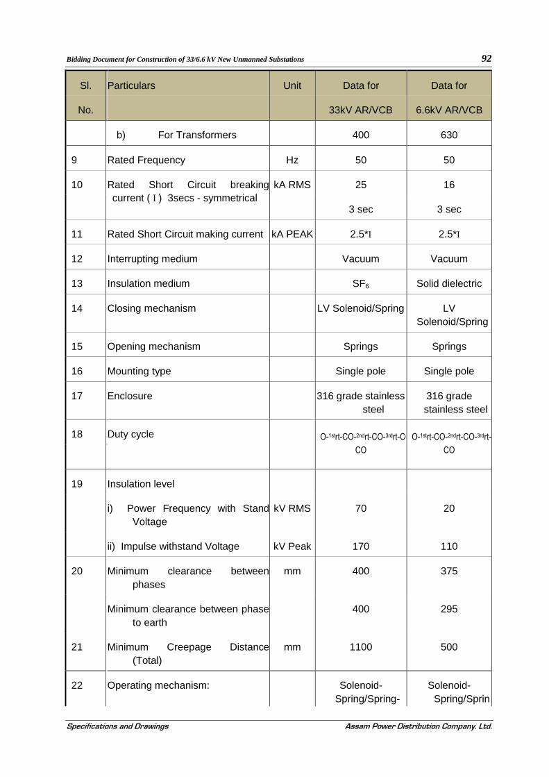
Bidding Document for Construction of 33/6.6 kV New Unmanned Substations 92
Specifications and Drawings Assam Power Distribution Company. Ltd.
Sl. Particulars Unit Data for Data for
No. 33kV AR/VCB 6.6kV AR/VCB
b) For Transformers 400 630
9 Rated Frequency Hz 50 50
10 Rated Short Circuit breaking current ( I ) 3secs - symmetrical
kA RMS 25 16
3 sec 3 sec
11 Rated Short Circuit making current kA PEAK 2.5*I 2.5*I
12 Interrupting medium Vacuum Vacuum
13 Insulation medium SF6 Solid dielectric
14 Closing mechanism LV Solenoid/Spring LV
Solenoid/Spring
15 Opening mechanism Springs Springs
16 Mounting type Single pole Single pole
17 Enclosure 316 grade stainless
steel 316 grade stainless steel
18 Duty cycle O-1strt-CO-2ndrt-CO-3rdrt-CO
CO
O-1strt-CO-2ndrt-CO-3rdrt-CO
CO
19 Insulation level
i) Power Frequency with Stand
Voltage kV RMS 70 20
ii) Impulse withstand Voltage kV Peak 170 110
20 Minimum clearance between
phases mm 400 375
Minimum clearance between phase
to earth 400 295
21 Minimum Creepage Distance
(Total) mm 1100 500
22 Operating mechanism: Solenoid-
Spring/Spring-Solenoid-
Spring/Sprin

Bidding Document for Construction of 33/6.6 kV New Unmanned Substations 93
Specifications and Drawings Assam Power Distribution Company. Ltd.
Sl. Particulars Unit Data for Data for
No. 33kV AR/VCB 6.6kV AR/VCB
Spring g-Spring
.b) Rated voltage of Shunt trip coil
& operating range V. DC 48[50% - 110%] 48 [50% - 110%]
c) Rated voltage of Closing coil &
operating range V. DC 48 [80% - 110%] 480 [80% - 110%]
d) No. of trip coils No 2 per AR 1 per AR
e) No. of closing coils No 1 per AR 1 per AR
f) Nos of expandable auxiliary I/O contacts & contact rating(Required for transformer &Incomer AR)
Nos
AMPS
12 I/P+8 O/P
(per AR)
10 A at 240V AC
& 16A at 48V DC
12 I/P+8 I/P (per CB)
10 A at 240V AC
& 16A at 48V DC
g) Minimum thickness of sheet steel for control cabinet
mm 3 3
h) Enclosure Protection IP55 IP55
23 Reclosing Three Phase Three Phase
auto reclosing auto reclosing
24 Support structure Galvanised Galvanised
(Painted / Galvanised)
25 All other parts (Painted / Galvanised)
Polyurethane
RAL 7032
(90 microns)
Polyurethane
RAL 7032
(90 microns)
26 Minimum size of control wiring
(Copper) Sq. mm 2.5 2.5
27 Protection

Bidding Document for Construction of 33/6.6 kV New Unmanned Substations 94
Specifications and Drawings Assam Power Distribution Company. Ltd.
Sl. Particulars Unit Data for Data for
No. 33kV AR/VCB 6.6kV AR/VCB
28
a) For transformer
b) For line
Numeric relay
-do-
O/C, E/F, SEF, Differential, OTI, WTI, PRV, Buchholz, OSRwith Backup Scheme
O/C, E/F, SEF
O/C, E/F SEF Differential, REF, with Backup Scheme
O/C, E/F, SEF
29
Measurement Digital Real time current, voltage, PF
Real time current, voltage, PF
30
Communication Protocol IEC60870-5-101/ IEC60870-5-104/IEC 61850 and IEC 103/
for relays DNP 3/MODBUS for
meters
IEC60870-5-101/ IEC60870-5-
104/IEC 61850 and
IEC 103/ for relays DNP 3/MODBUS for meters
31
Communication Port RS 232, RS 485 & Ethernet
RS 232, RS 485 & Ethernet
32 Supervisory RTU RTU
5.5.0. DEFINITIONS AND ABBREVIATIONS
a) Auto-recloser (AR): A mechanical switching device that, after opening, closes automatically after a predetermined time. Several reclosures could occur before lockout.
b) Cold load pick-up (CLP) feature: A feature that allows modification of the over-current protection characteristics in order to prevent relay maloperation under conditions of system energisation.
c) Dead time: The time between the instant that the current is interrupted by the AR and the instant the contact of the AR closes as a result of an automatic reclose operation. [IEC 50-448-04-09]
d) Definite time lag (DTL) protection element: A protection element with a settable time delay that is constant above the pick-up current setting.

Bidding Document for Construction of 33/6.6 kV New Unmanned Substations 95
Specifications and Drawings Assam Power Distribution Company. Ltd.
e) Delayed protection operation: The protection functionality enabling delayed circuit-breaker operation, whether this is due to an IDMTL or DTL protection element.
f) Disc reset time: The time required for the disc of an electromechanical IDMTL protection relay to turn back to its original position after it has turned to the position where a protection operation was initiated.
g) Effectively earthed system: An earthed system in which the healthy phase power frequency phase-to-earth over voltages associated with earth faults are limited to 80% of the highest phase-to-phase voltage of the system.
h) Fast curve protection element: A family of curves with operating times approximately constant (slightly inverse) relative to the multiple of pick-up setting.
i) Instantaneous protection element: An element with no intentional time delay active above a pre-determined pick-up current setting.
j) Inverse definite minimum time (IDMT) protection element: A protection element the minimum operating time of which is adjustable and is inversely proportional to the fault current.
k) Pole-mounted remote terminal unit (PMRTU): A remote terminal unit that is designed for pole mounting and that operates specific pole-mounted equipment remotely.
l) Rapid protection operation: The protection functionality enabling rapid circuit-breaker operation, whether this is due to an instantaneous, fast curve, or a definite time delay protection element with relatively short definite time delay.
m) Reset time: The time duration after a circuit-breaker close operation for which the measured currents are below a fault detecting level. On the expiry of this time the protection sequence resets.
n) Secure control: A single mechanically non-latching switch that effects one state of a control function only. An example of which is either a non-latching switch or two separate push buttons that effect one state of a control function only in each position. If a control is activated repeatedly it only effects that state and does not change the state of the control.
o) Sensitive earth fault (SEF) relay: A relay that is sensitive to very low earth fault currents and in which the operating settings are for current magnitude and definite time delay.
p) Supervisory: Remote control and indications of an AR or a PMRTU by means of a telecommunications link.
q) Toggled control: A single mechanically non-latching switch/push-button that enables a single control function on the first operation of the switch/push-button and disables the function on the second operation of the same switch/push button.

Bidding Document for Construction of 33/6.6 kV New Unmanned Substations 96
Specifications and Drawings Assam Power Distribution Company. Ltd.
r) Zone sequence co-ordination (ZSC): The feature that allows protection devices to maintain sequence co-ordination for combinations of rapid and delayed protection operations.
5.6.0. Mounting
5.6.1. The AR shall be suitable for single pole mounting.
5.6.2. Adequately rated lifting eyes shall be provided and they shall be designed to allow the completely assembled AR (surge arresters fitted) to be lifted without recourse to a sling spreader. The diameter of the eyes shall be a minimum of 30mm.
5.6.3. Suitable mounting brackets for surge arresters shall be provided on the line side and on the load side of the AR, adjacent to the bushings.
5.6.4. The AR shall be fitted with an external M12 earthing stud, complete with a nut, lock nut and spring washer.
5.6.5. The AR shall have laser cut markings on each bushings marked U1 V1 W1 for the normal line side and U2 V2 W2 for normal load side.
5.6.6. A detailed drawing of the single pole AR mounting arrangement with surge arresters fitted shall be provided. The minimum phase-to-earth clearances shall be as per relevant IS and is to be indicated on the drawing.
5.6.7. The mass of the mounting hardware, the AR and the control cabinet and cable shall be stated in the tender documentation.
5.7.0. Bushings
5.7.1. Terminals
a) For 33KV AR, the preferred arrangement for bushing is a fully insulated bushing arrangement achieved by using cyclo aliphatic epoxy resign bushings and silicone rubber bushing boots together with 3 meters 185 mm2, single core, XLPE insulated aluminum water blocked cable tails to provide a fully insulated bushing arrangement.
b) For 6.6KV AR, the preferred arrangement for bushing is a fully insulated bushing arrangement achieved by using cyclo aliphatic epoxy resign bushings and silicone rubber bushing boots together with 3 meters 300 mm2, single core, XLPE insulated aluminum water blocked cable tails to provide a fully insulated bushing.
5.7.2. Material
The following bushing materials are acceptable:
a) Outdoor Cyclo aliphatic epoxy resin and/or Silicone rubber
b) Porcelain bushings and EPDM rubber are not acceptable.
c) Minimum acceptable creepage is 1100 mm for 33 KV AR and 300 mm for 6.6 KV AR..
5.8.0. Finish

Bidding Document for Construction of 33/6.6 kV New Unmanned Substations 97
Specifications and Drawings Assam Power Distribution Company. Ltd.
a) All interior and exterior ferrous surfaces of auto-reclosers and control cabinets shall be manufactured from 316 marine grade stainless steel. All support structures and associated bolts and nuts with these parts, shall be hot-dip galvanized.
b) Suitable precautions shall be implemented to prevent corrosion due to the use of dissimilar materials.
5.9.0. Control equipment
5.9.1. Control cabinet
a) Cabinets that house equipment for protection and control shall be mounted independently of the AR.
b) Suitable ultraviolet-resistant cable, shall be provided to connect the AR to the control cabinet.
c) It shall be possible to disconnect the cable at the AR while the AR is connected to the power system, without causing damage or mal-operation: care shall be taken that CTs are not open circuited. A robust, multi-pin weatherproof connector shall be supplied. The female part of the connector shall be mounted on the AR and the male part shall be mounted on the cable. Preference will be given to products supplying connectors at both the AR and the control cabinet.
d) Cabinets shall be adequately sealed and dust protected and shall be internally treated to prevent moisture condensation. The degree of protection shall be IP 55.
e) The supplier shall ensure that the equipment housed in the control cabinet can withstand the heating effect of direct solar radiation without causing failure and/or mal-operation. Details shall be provided in the tender documentation.
f) The cabinet shall make provision for bottom entry of three cables. This shall be done with a pre-punched suitable sized diameter holes. The holes shall be suitably blanked off.
g) The cabinet shall be fitted with an external M12 earthing stud with a nut, lock nut and a serrated washer.
h) The door of the cabinet shall be fitted with a robust fastening arrangement that is capable of being secured by a padlock that has a shackle of 8 mm diameter.
i) The cabinet shall be easily removable for workshop repair purposes.
5.9.2. Electronic control equipment
5.9.2.1. The controls shall not suffer any damage if one or more poles of the circuit breaker fail to respond to either a trip or a close command.
5.9.2.2. Electronic modules shall perform continuous diagnostic monitoring and shall contain hardware and software watchdog checking.
5.10.0. Protection characteristics
5.10.1. General

Bidding Document for Construction of 33/6.6 kV New Unmanned Substations 98
Specifications and Drawings Assam Power Distribution Company. Ltd.
i) The ratio of drop-off current to pick-up current shall be at least 95 % for all protection functions.
ii) The E/F and SEF functions shall be equipped with harmonic filtering to prevent operation when harmonics are present in the primary residual earth currents. A low pass filter with:
a) 2nd harmonic rejection > 6 1; and
b) 3rd harmonic rejection > 50 1 shall be supplied. Both the SEF function and its filter shall be described in the tender documentation
5.10.2. All protection functions, i.e. over-current (O/C), earth fault (E/F) and sensitive earth fault (SEF) shall have elements with characteristics that comply with IEC 255.
5.10.3. The sequence of trip and auto-reclose characteristics for O/C, E/F and SEF shall be programmable to enable:
a) the selection of any combination of the available elements for each trip in the trip-and-reclose sequence; and
b) Separate trip-and-reclose sequences for O/C, E/F and SEF.
5.10.4. In case of IDMTL protection elements the AR shall preferably be provided with a disc reset timer that simulates the resetting functionality of an upstream electromechanical induction disc relay by implementing a disc reset timer. The length of the time delay shall preferably be settable to be able to simulate the upstream device (settable between 5s and 20 s), however, if a fixed time delay is provided it should be between 4s and 5s.
5.10.5. A zone sequence co-ordination (ZSC) feature shall be provided to ensure trip-close sequence co-ordination for combinations of rapid and delayed protection operations applied to series ars. ZSC functionality shall be such that:
a) an AR senses the presence of an over-current or earth fault, as well as the clearance of that fault by another device and proceeds to the next protection operation in its own sequence; and
b) it proceeds in its sequence of rapid protection operations only, allowing the full number of delayed operations to be executed for in-zone conditions.
5.10.6. Loss of Phase (LOP) protection shall be provided to ensure the protection functionality of AR as below:
a) AR should trip with no auto-reclose in case if there is a loss of voltage on one or two phases on the upstream part of the line. Loss of supply on all three phases shall not generate the protection trip.
b) Facility to turn LOP ON or OFF without affecting other protection functions of the device. Pass-word or other form of access control shall be provided

Bidding Document for Construction of 33/6.6 kV New Unmanned Substations 99
Specifications and Drawings Assam Power Distribution Company. Ltd.
c) The parameters of configuration of LOP shall include the voltage level (phase to ground) and time of loss of supply on one or two phases. The voltage level shall be configurable from 5000 to 19000 Volts (for 33KV) and 5000 to 9000 (for 11KV) with steps not greater then 250 V. Time range shall be configurable from 1 to 60 sec with steps not greater then 1 sec.
5.10.7. The information about LOP operation in case of the protection trip shall be recorded accordingly with indication of the phase(s) causing the trip of AR. The information about LOP operation shall be easily assessable.
d) Rapid protection operation shall be possible by selecting a fast curve or instantaneous protection element.
Co-ordination of the fast curves or instantaneous protection elements between two devices in series shall be possible either by selecting suitable curves from a family or by addition of a selectable time increment, typically 0,05s to 3s, in 0,05s steps, or any other acceptable solution.
5.10.8. Long protection operating times associated with fault levels marginally above the pick-up setting of the IDMTL protection element shall be avoided by the provision of a Low Set Definite Time element with the following features:
a) it shall be possible to enable or disable the element. When enabled it shall be active simultaneously as an overlay with all selected elements;
b) the element shall have the same pick-up current setting as the IDMTL element; and
c) the time delay shall be selectable from 2s to 10s, in 1s steps. The time delay shall be independent of any curve manipulation.
5.10.9. A High Set Instantaneous element with a selectable time delay shall be provided, with the following features:
a) it shall be possible to enable or disable the element. When enabled it shall be active simultaneously as an overlay with all selected elements;
b) circuit-breaker lock-out as a result of an operation due to the High Set Instantaneous element shall be selectable;
c) the pick-up setting range of this element shall be at least 100 % to 1500 % of the over-current setting and shall be independent of any curve manipulation; and
d) the time delay shall be selectable from instantaneous to 1s, in 0,05 s steps. The time delay shall be independent of any curve manipulation.
5.10.10. A cold load pick-up (CLP) feature shall be provided that allows user selectable modification of protection element characteristics under conditions of system energization. The CLP function may be provided in one of the following two ways:
a) The instantaneous O/C element and the Low Set Definite Time O/C element could be blocked for the CLP time duration; and

Bidding Document for Construction of 33/6.6 kV New Unmanned Substations 100
Specifications and Drawings Assam Power Distribution Company. Ltd.
b) The pick-up current setting of the IDMTL O/C element and the Low Set Definite Time O/C element may be modified with a settable factor to increase the pick-up current of these elements for the CLP duration. The instantaneous O/C element should be blocked for this time. This is the preferred method.
The CLP function shall have the following characteristics:
i. the CLP function shall not in any way interfere with any of the other functions'/elements' pick-up current settings except as mentioned above;
ii. the CLP functionality shall be such that the active duration of the CLP is selectable from 0 min to 20 min in 1 min steps; and
iii. the modification factor should be settable from 1 to 2 in steps of 0,1.
5.11.0. Earth fault function
5.11.1. The earth fault setting range shall detect primary earth fault currents down to 20 A.
5.11.2. Delayed protection operation shall be possible by selecting an IDMTL element with NI, VI or El curve, or a definite time protection element with time delay from 0.05s to 10s, in 0,05s steps.
5.11.3. Rapid protection operation shall be possible by selecting a fast curve or instantaneous protection element.
5.11.4. Co-ordination of the fast curves or instantaneous protection elements between two devices in series shall be possible either by selecting suitable curves from a family or by addition of a selectable time increment, typically 0.05s to 3s, in 0.05s steps, or any other acceptable solution.
5.11.5. A High Set Instantaneous element with a selectable time delay shall be provided with the following features:
a) it shall be possible to enable or disable the element. When enabled it shall be active simultaneously as an overlay with all selected elements;
b) circuit-breaker lockout as a result of an operation due to the High Set Instantaneous element shall be selectable;
c) he pick-up setting range of this element shall be at least 100 % to 1500 % of the earth fault setting and shall be independent of any curve manipulation; and
d) he time delay shall be selectable from 0,05s to 1s, in 05s steps. The time delay shall be independent of any curve manipulation.
5.12.0. Sensitive earth fault (SEF) function
5.12.1. A primary earth fault current of 4A to 20A in steps not exceeding 1A shall be detectable.
Delayed protection operation shall be possible by selecting a definite time protection element with time delay from 3s to 25s, in 1s steps.

Bidding Document for Construction of 33/6.6 kV New Unmanned Substations 101
Specifications and Drawings Assam Power Distribution Company. Ltd.
5.13.0. Auto-reclose operation parameters
5.13.1. The number of sequential trips to reach lockout shall be selectable to be either 1,2,3 or 4.
5.13.2. Reset times shall ideally be separately selectable for SEF and the combination of over-current and earth fault functions. The reset time shall be selectable from 5s to 120s in 1s steps.
5.13.3. Dead times shall ideally be separately selectable for SEF and the combination of over-current and earth fault functions. The dead time between each -successive reclosure shall be independently selectable from instantaneous to 5s for the first reclosure and from a minimum of 2s up to a maximum of 120s for subsequent reclosures.
5.13.4. A close instruction initiated locally or remotely during a dead time shall result in lockout if the fault is still present upon closure.
5.14.0. Statistical measurement functions
5.14.1. The characteristics of the statistical measurement functions shall be as follows
5.14.2. Measurement shall be done with three-phase-4-wire method.
5.14.3. Quantities to be measured / calculated with class 0.5 accuracy are:
a) r.m.s. phase-to-phase and phase-to-neutral voltage of all three phases:
b) r.m.s current per phase
c) three phase active power in kW
d) three phase reactive power in kvars
e) total three-phase active energy in kWh
f) Power factor
g) Maximum demand
h) Harmonic analysis
i) Wave form capture
j) Fault stimulator
5.14.4. The real power energy, reactive energy and apparent energy measurement should be cumulative. While maximum demand measurement shall be integrated with respect to time. With selectable time integration periods of 5 min, 15 min, 30 min or 60 min. The data buffer shall work on the FIFO principle and a minimum size for the data buffer shall store values for 4 months.
5.14.5. The voltage factor of the voltage transformers shall be a minimum of 1.9 for 8 hours.

Bidding Document for Construction of 33/6.6 kV New Unmanned Substations 102
Specifications and Drawings Assam Power Distribution Company. Ltd.
5.14.6. CB and Control element shall have the facilities to record the number and duration of outages. The information shall be assessable locally or remotely using SCADA system. The following parameters shall be recorded:
a) Cumulative total number of outages
b) Cumulative total outage duration
c) Time and duration of each outage
5.15.0. Local control and indication:
5.15.1. The local control and indication shall be as given in Table-1:
Table-1- Minimum specification of local controls ad indications:
1
Item
2
Features
3
Remarks
Local control Local/Remote 2 position key switchable
(See note 1) Circuit-breaker open
Circuit-breaker close
ARC ON/OFF
SEF ON/OFF
(see note 3)
Secure control
Secure control
Secure or toggled control
Secure or toggled control
Local indication Local/Remote (see note 3)
(See note 1) Circuit-breaker open
Circuit-breaker close
Circuit-breaker lock-out
ARC ON/OFF
SEF ON/OFF
Protection operation See 5.15.7
Controller not healthy (see note 2)
SF , Alarm See 5.15.9
AC fail

Bidding Document for Construction of 33/6.6 kV New Unmanned Substations 103
Specifications and Drawings Assam Power Distribution Company. Ltd.
DC abnormal See 5.20.7
DC fail
Charger fail
Local Analog indication
(See note 1)
• r.m.s phase-to-phase to neutral voltage of all three phases
• r.m.s current per phase
• three phase active power in KW three phase reactive power in kvars
• total three-phase active energy in kWh
• Power factor
• Maximum demand
NOTES:
Note 1: The local control and the local indication features on the control panel shall be labeled as presented in column 2, where applicable. The type of switch used for local control shall not allow for a conflict to exist between the switch position and the function status.
Note 2: The Controller not healthy indication shall indicate the control equipment not healthy (watchdog) function operated. It shall not operate during the normal pole mounted switch operating cycle. This indication should remain active until the unhealthy state that initiated it returns to normal.
Note 3: The three-position switch (labeled as below) shall allow the AR controller to be set in the following modes:
Remote: In this mode a local operator can trip the AR and change the mode. A remote operator can trip or close the AR and change configuration parameters. All reporting functions are active.
Local: In this mode a local operator can trip and close the AR and change configuration parameters. All reporting functions are active.
5.15.2. All local controls and indications shall be accessible in adverse weather condition.

Bidding Document for Construction of 33/6.6 kV New Unmanned Substations 104
Specifications and Drawings Assam Power Distribution Company. Ltd.
5.15.3. The AR shall be provided with external levers to permit manual operation, using an insulated operating stick, to open, close, lock-out and reset the AR from ground level . Where these operations can be performed at the control cabinet, it shall only be necessary to provide a mechanical means to open and lockout the circuit breaker using an insulated operating stick.
5.15.4. The AR status shall be clearly visible from ground level. “Opened” shall be indicated with a green “O”. “Closed” shall be indicated by a red “I”. Alternative indications shall be subject to approval by the purchaser.
5.15.5. Pressure relief facilities shall be provided to enable the AR to withstand safely the effects of excessive pressure rise due to an internal fault.
5.15.6. Malfunction of the AR shall not pose a safety hazard to the operator due to the recoil or backlash of items such as external operating rods, ranks and levers.
5.15.7. Easily available (i.e maximum of one keystroke) local indication of protection operation shall be provided for at least the last operation of the AR. The function, phase involved and the current magnitude shall be indicated.
5.15.8. Switches used for local control shall offer the type of control described in table 1 i.e. secure or toggled control. Electronic keypad controls shall offer ‘quick key’ (maximum of one keystroke) access to the controls in table1 if not implemented with switches
5.15.9. ARs using SF, as an arc extinguishing/Insulating medium shall:
a) Provide a low gas pressure indication at a gas pressure that enables safe operation of the AR
b) Prevent closing of the AR after it has opened under the above-described condition
c) Be provided with a method of inhibiting any operation of the AR in the event of the gas pressure dropping below a safe pressure.
5.16.0. Remote control and indication
5.16.1. The remote controls and indication shall be as given in table 2
Table 2- Minimum specification of remote controls and indications
1
Item
2
Features
3
Remarks
Remote control Circuit-breaker open
Circuit-breaker close
Secure control
Secure control

Bidding Document for Construction of 33/6.6 kV New Unmanned Substations 105
Specifications and Drawings Assam Power Distribution Company. Ltd.
ARC On
ARC OFF
SEF ON
SEF OFF
Secure control
Secure control
Secure control
Secure control
Remote indication
(See note 3)
Local/Remote
Circuit-breaker open
Circuit-breaker close
ARC On
ARC OFF
SEF ON
SEF OFF
IDMTL O/C Trip
Low Set DTL O/C Trip
Rapid E/F Trip
High Set E/F Trip
SEF Trip
ARC
Controller not healthy
SF, Alarm
AC fail
DC abnormal
DC fail
Charger fail
(See note 2)
(see note 4)
(see note 1)
See 4.8.9
See 5.20.7
Analog indication
(See note 3)
• r.m.s phase-to-phase and phase to neutral voltage of all three phases
• r.m.s current per phase
• three phase active power in KW

Bidding Document for Construction of 33/6.6 kV New Unmanned Substations 106
Specifications and Drawings Assam Power Distribution Company. Ltd.
• three phase reactive power in kvars total three-phase active energy in kWh
• Power factor
• Maximum demand
Note 1: The Controller not healthy indication shall indicate the control equipment not healthy (watchdog) function operated. It shall not operate during the normal pole mounted switch operating cycle. This indication should remain active until the unhealthy state that initiated it returns to normal.
Note 2: The two-position switch (labeled as below) shall allow the AR controller to be set in the following modes:
Remote: In this mode a local operator can trip the AR and change the mode. A remote operator can trip or close the AR and change configuration parameters. All reporting functions are active.
Local: In this mode a local operator can trip and close the AR and change configuration parameters. Only monitoring functions are available to remote operators. The local and remote positions shall be indicated separately.
Note 3: The ARC indication shall give alarm with any ARC attempt.
5.17.0. Local Engineering
5.17.1. The AR controller shall contain a real time clock (with leap year support) that can be set both locally and remotely. It shall be possible to synchronise the clock with the control SCADA centre, using the time synchronising standards (IEC-101/IEC-104 or SNTP protocol.
5.17.2. A facility for selecting all the protection, operating and communications characteristics shall be locally available in the control cabinet. Optional password protection against unauthorized changes shall be available.
5.17.3. Non-Volatile memory storage shall be sized to store the following minimum data:
5.17.4. All operating, protection and communications parameters.
5.17.5. An event record containing at least 3000 events (a protection event is defined as all operations in a sequence until successful sequence reset or lockout). The actual number available shall be stated in the tender documentation.
5.17.6. Refer to clause 5.14.4
5.17.7. Maximum demand information Maximum demand shall have the facilities to be configured for weekly or monthly demand.
5.17.8. A pointer shall be provided to indicate up to where the data was last read. This will enable regular uploading of the data without re-loading of previously read data.

Bidding Document for Construction of 33/6.6 kV New Unmanned Substations 107
Specifications and Drawings Assam Power Distribution Company. Ltd.
5.17.9. All events shall be time and date stamped with a resolution of at least 10 ms relative to the on-board real time clock.
5.18.0. Tele-control requirements
5.18.1. The AR controller shall detect and report disconnection of the control cable between the controller and AR.
5.18.2. It shall be possible to operate AR, change the active protection group, turn Auto-Recloser capabilities ON/OFF and turn E/F and SEF ON/OFF remotely using the protocol specified in 5.19.1.8 Error! Reference source not found..
5.19.0. Communications
5.19.1. Communication Overview
5.19.1.1. Technical Requirement for Unmanned Substation Communication.
5.19.1.2. A local control room in the substation shall have all the controls of switchgear from local PC For the Local & Remote control, monitoring and adjustments software solutions shall be provided to carryout following tasks as minimum
o ON/OFF Operations
o Change the protection and control settings
o Up-Load the Event / Data and Demand Log
o Monitor Contact wear and Breaker health
o Monitor VCB Battery and Battery Charger
o Communications settings
o Apply Work-Tags for maintenance
o Call-out configuration (In the event of pre-programmed alarm for call-out, the device calls back the remote station to log the alarm)
o Send messages to the concerned field staff, in case of a call-out, by means of SMS, Voice Call, E-Mail etc. (Depending on the local resources available, GSM Service, LAN Administrator etc.)
5.19.1.3. Event Logging, configured History & Demand Reports
The system is capable of logging very comprehensive data in three different categories
a) Event Logging
This log should have all the events observed by the device including ON/OFF operation, Local commands, protection element pick-up and trip, change of settings, Aux supply, fault level (Interrupted current valus) Battery low etc.
b) Demand Logging
Should upload from the devices all records of weekly and monthly demand, which can be uploaded by the software from any remote location and used for analysis of load behavior on each feeder including the total no of outages and duration of outages

Bidding Document for Construction of 33/6.6 kV New Unmanned Substations 108
Specifications and Drawings Assam Power Distribution Company. Ltd.
c) Configured History
Should be able to up-load recorded user defined parameters periodically at user defined frequency ie. 15/30/60 min. This data can be up-loaded from local or remote software
d) Alarms / Call-outs
There are several type of alarms, that can be configured to initiate an emergency call-out. If any of the user defined alarm occurs in any of the substation feeders, the device immediately calls up the Remote Control Center which in turn initiates a alert system by sending SMS messages, Pre-recorded Voice Messages and E-Mails etc. to user configured locations
e) Provision for GPRS Routers with built-in Modbus/IEC Gateways for data transmission, connecting cords/cables, antenna etc. shall be kept. The utility in its discretion may also ask for commissioning and training/handholding, troubleshooting from the supplier
f) Computer System
The firm will also offer a Xeon Server and a node of the good quality suitable computer system (IBM, HP or Dell make) with latest configurations
g) Specification of Server
a. Industrial grade processor with advance configuration
b. 3.2 GHz or higher speed
c. 2 MB or higher L2 ECC Cache
d. Ultra fast Throughput with 800 MHz FSB
e. 4 GB of DDR2 RAM operating at 400 MHz or higher expendable up to 16GB
f. Server works/Intel server class chipset
g. 3x73 GB Ultra Wide SCSI-III Disk(15000rpm) Hot Swap
h. Dual Channel Ultra-III SCSI Controller (320MBPS) with RAID(0,1,5) having 128MB RAM
i. Minimum 5 PCI/PCI-X Slot
j. Auto-sensing full duplex 10/100/1000 MBPS Ethernet Card
k. Minimum 6 Hot Swap 1.0” drive bays & two 5.25” bays free
l. DVD Writer
m. 17” LCD Color Monitor
n. 1.44MB FDD
o. PS/2 104Keys Keyboard
p. Server Management features
q. Server Configuration and Software Loading Facility
r. Windows 2000/2003 Server
s. UPS 2 KVA battery with 3 hrs backup

Bidding Document for Construction of 33/6.6 kV New Unmanned Substations 109
Specifications and Drawings Assam Power Distribution Company. Ltd.
t. GSM Modem for SMS
u. Multimedia Speakers for alarm annunciation
h) Specification of Laptop
a) HP/Dell
b) Windows 7
c) Intel Core 2 Duo, 300 GB HDD, 1 GB RAM, DVD R/W
d) Internal Modem
The firm shall also offer Computer room furniture (two computer desks & Six chairs) of reputed make and ACs of standard make to be installed, at Central Stations.
5.19.1.4. As a minimum, following independent communication ports will be provided, that allow for simultaneous operation
1. RS 232 (Configurable for Modbus, DNP3, IEC 101
2. RS 485 (Configurable for Modbus, DNP3, IEC 101
3. Ethernet.(Configurable for IEC 104)
4. USB Port for Local connection of Laptop PC
5.19.1.5. To upload the non-volatile data to and from a personal computer. The requirements of the personal computer shall be stated in the tender documentation.
5.19.1.6. To interface to remote communications equipment (e.g. GSM / CDMA / GPRS / PSTN modems, radio-modems and Fiber Optic Modems).
5.19.1.7. One of the RS-232 port shall support full asynchronous V.24 functionality.
5.19.1.8. The protocol to be supported by the AR controller for remote communications shall be as follows:
a) Support of IEC 870-5-101 & IEC 870-5-104 protocol for Remote SCADA
b) MODBUS protocol over RS 485 to communicate with the External Numerical Relays/Energy meters/RTCC Panels
The communication interface should be designed in such a way that the RTU can communicate both local remote station as well as SCADA.. The controller should include on board RTU and a radio power supply user programmable between 5-15 V dc and rated for 3 A continuous, or 5 A for 30 seconds with a 20 % duty cycle.
5.20.0. Power supplies
5.20.1. The AR system shall provide power for the electronics, operation of the AR and operation of the communications equipment (e.g. radio or GSM-modem).
5.20.2. Primary supply: Preference will be given to the ability to obtain primary power directly from the HV power system requiring no additional primary supply connection.

Bidding Document for Construction of 33/6.6 kV New Unmanned Substations 110
Specifications and Drawings Assam Power Distribution Company. Ltd.
5.20.3. Test supply: The AR shall accept an external AC 230 V 50 Hz supply.
5.20.4. Auxiliary supply: An auxiliary supply with the following minimum characteristics shall be provided
5.20.5. One battery and constant voltage charger with current limiting shall be part of the AR. Battery standby time shall not be less than 24 h, allowing for ten AR operations and a Transmit: Receive: Standby duty cycle of 5:5:90 from a 5 W output ratio. The battery shall recharge to 80 % of its capacity in a maximum of 15 h. The total number of circuit-breaker operations under the above communications scenario shall be at least 10 AR operations preventing closing if the battery will not have enough stored energy to open the circuit- breaker for a protection trip condition. Details will be stated in the tender documentation.
5.20.6. Batteries shall be disconnected at the manufacturer's specified minimum voltage.
5.20.7. Battery Low' indication shall be available locally and remotely and shall include a battery test. The indication of "Battery Low" status shall allow for a further ten AR operations.
5.20.8. The minimum battery life expectancy shall be 5 years. Details of the guaranteed life expectancy of the battery shall be stated in the tender documentation.
5.21.0. Maintenance and commissioning
All the communications equipment shall be easily accessible in the control cabinet. Wiring of "communications links in the control cabinet shall permit the connection of a temporary protocol-Monitor. It shall be possible to perform secondary injection testing while the AR is communicating with the center.
5.21.1. It shall be Possible to disconnect the AR circuit breaker and connect a simulated breaker to the control cabinet for testing purposes.
5.21.2. The AR shall not malfunction while the radio is transmitting via an antenna in close proximity and the control cabinet door is open.
5.21.3. Provision shall be made in the control cabinet for individually isolating the power supply to/from the following:
a) battery;
b) battery charger;
c) radio; and
d) primary supply to the control cabinet electronics.
5.22.0. Rating plate
Each AR shall bear a rating plate of an intrinsically corrosion-resistant material, indelibly marked with the sea-level rating for which the equipment has been type tested. The rating plate shall be indelibly marked with:

Bidding Document for Construction of 33/6.6 kV New Unmanned Substations 111
Specifications and Drawings Assam Power Distribution Company. Ltd.
a. the manufacturer's name;
b. the equipment type designation and serial number of the ar;
c. the mass, in kilograms;
d. the date of manufacture;
e. the voltage transformer ratio, class and burden.
f. auxiliary supply voltage (if applicable); and
5.23.0. Additional information
The following shall be submitted with the tender.
5.23.1. Circuit breaker details
a) manufacturer;
b) type designation;
c) place of manufacture;
d) short circuit breaking capacity; 3s 1s
e) asymmetrical breaking current;
f) peak making current; and
g) critical current (maximum instantaneous peak).
5.23.2. A schematic-wiring diagram of the AR offered.
5.23.3. A general-arrangement drawing of the AR offered.
5.23.4. Details of the maintenance and operating equipment and procedures needed and a detailed parts list of the various components.
5.23.5. A description of the AR operation, with instruction and maintenance manuals, including maintenance schedules, protection characteristics, communications facilities, the method of applying settings to relays and controls, together with any software required and the cost thereof. The software requirements shall be stated in the tender documentation.
5.23.6. A list of recommended spares and tools, quoting the prices of each item and its availability.
5.23.7. Details of technical back-up facilities available. These details shall be stated in the tender documentation.
5.23.8. Details of the class, ratio(s) and burden of the protection current transformer and voltage transformer, if supplied, shall be stated in the tender documentation.
5.23.9. Where applicable details of the low gas pressure alarm/lock-out philosophy;
5.23.10. Details of AR service history:

Bidding Document for Construction of 33/6.6 kV New Unmanned Substations 112
Specifications and Drawings Assam Power Distribution Company. Ltd.
a) how many in service, where and for what period; and
b) contact names and numbers.
5.23.11. Details of LV trip/close coil if available as an option
5.23.12. Power requirements for a close operation
5.23.13. The maximum achievable separation between the control unit and the circuit breaker.
5.23.14. Full details of the protocol implementation and the complete point database.
5.24.0. TESTS
5.24.1. Type tests
a) The AR shall have been type tested in accordance with, and found to comply with, the requirements of either IEC 62271 or ANSI/IEEE C37.60-1981 for the following, and the appropriate values shall be stated in the tender documentation:
b) Interrupting performance (automatic operation).
c) Interrupting performance (manual operation).
d) Operating duty.
e) Making current.
f) Minimum tripping current.
g) Insulation (dielectric tests).
h) Radio interference voltage.
i) Temperature rise.
j) Mechanical operations.
k) Control equipment surge withstand capability.
5.24.2. The control cabinet and associated electronics shall have been type tested in accordance with UNIPEDE NORM (SPEC) 13 (1995): Automation and Control Apparatus for Generating Stations and Substations: Electromagnetic Compatibility Immunity Requirements. The environment shall be considered as failing in the HV substation category, according to NORM (SPEC)13.
5.24.3. Test records (on identical equipment) in the form of validated copies of test certificates issued by a recognized testing authority shall be submitted with the tender documentation.
5.24.4. Routine tests
Routine tests, as required in the relevant standards, shall be carried out as a normal requirement of the contract and, unless otherwise agreed upon, shall be witnessed by the employer or by his appointed representative. No additional charge is applicable for such tests or for the production or presentation of documentation related to routine tests.

Bidding Document for Construction of 33/6.6 kV New Unmanned Substations 113
Specifications and Drawings Assam Power Distribution Company. Ltd.
Duplicate copies of routine test certificates shall be supplied together with the equipment when the latter is delivered to the final destination stated in the order.
5.25.0. PACKING/DOCUMENTATION
5.25.1. Packing
All equipment shall be carefully packed to prevent damage or deterioration during normal transportation, handling and storage.
Each container shall bear the following information on the outside of the container:
a) The address of the destination
b) The gross mass, in kilograms
c) The name of the manufacturer
d) The purchaser's order number and port of destination
5.26.0. Documentation
Each AR shall be supplied complete with the documentation specified in Items as per clause 5.23.1, 5.23.2. 5.23.3 and 5.23.4, together with the routine test certificates specified in clause 5.24.4.
5.27.0. SPECIAL TOOLS AND TACKLES
5.27.1. The Bidder shall furnish a list of any special tools and tackles required for maintenance and operation purposes with recommended quantities for each substation.

Bidding Document for Construction of 33/6.6 kV New Unmanned Substations 114
Specifications and Drawings Assam Power Distribution Company. Ltd.
SECTION - 6
TECHNICAL SPECIFICATION OF OUTDOOR
CURRENT AND POTENTIAL TRANSFORMERS
6.1.0. SCOPE OF CONTRACT
6.1.1. This Section of the Specification covers general requirements for design, engineering, manufacture, assembly and testing at manufacturer’s works of 33kV and 6.6 kV outdoor Current and Potential Transformers.
6.2.0. STANDARDS
6.2.1. The equipment covered by this specification shall, unless otherwise stated be designed, constructed and tested in accordance with the latest revisions of relevant Indian Standards and shall conform to the regulations of local statutory authorities.
6.2.2. In case of any conflict between the Standards and this specification, this specification shall govern.
6.2.3. The current transformer shall comply also with the latest issue of the following Indian standard.
(i) IS: 2705(Part-I) Current transformers: General requirement.
(ii) IS: 2705(Part-II) Current transformers : Measuring Current transformers
(iii) IS: 2705(Part-III) Current transformers : Protective Current transformers
(iv) IS: 2705(Part-IV) Current transformers: Protective Current transformers for special purpose application.
(v) IS: 3156(Part-I) Potential transformers: General requirement.
(vi) IS: 3156 (Part-II) Potential transformers : Measuring Potential transformers
(vii) IS: 3156 (Part-III) Potential transformers : Protective Potential transformers
6.3.0. GENERAL REQUIREMENTS
6.3.1. The cores of the instrument transformers shall be of high grade, non-aging CRC steel of low hysteresis loss and high permeability.
6.3.2. Instrument transformers shall be of Dead Tank design or Live Tank design.

Bidding Document for Construction of 33/6.6 kV New Unmanned Substations 115
Specifications and Drawings Assam Power Distribution Company. Ltd.
6.3.3. The instrument transformers shall be truly hermetically sealed polycrete type
6.3.4. A complete leak proof secondary terminal arrangement shall be provided with each instrument transformers, secondary terminal shall be brought into weather, dust and vermin proof terminal box. Secondary terminal boxes shall be provided with facilities for easy earthing, shorting, insulating and testing of secondary circuits. The terminal boxes shall be suitable for connection of control cable gland.
6.3.5. All instrument transformers shall be of single phase unit.
6.3.6. The instrument transformers shall be so designed to withstand the effects of temperature, wind load, short circuit conditions and other adverse conditions.
6.3.7. All similar parts, particularly removable ones, shall be interchangeable with one another.
6.3.8. All cable ferrules, lugs, tags, etc. required for identification and cabling shall be supplied complete for speedy erection and commissioning as per approved schematics.
6.3.9. The instrument transformers shall be designed to ensure that condensation of moisture is controlled by proper selection of organic insulating materials having low moisture absorbing characteristics.
6.3.10. All steel work shall be degreased, pickled and phosphated and then applied with two coats of Zinc Chromate primer and two coats of polyurethane paint.
6.4.0. COMMON MARSHALLING BOXES
6.4.1. The outdoor type common marshalling boxes shall conform to the latest edition of IS 5039 and other general requirements specified hereunder.
6.4.2. The common marshalling boxes shall be suitable for mounting on the steel mounting structures of the instrument transformers.
6.4.3. One common marshalling box shall be supplied with each set of instrument transformers. The marshalling box shall be made of sheet steel and weather proof. The thickness of sheet steel used shall be not less than 3.0 mm. It is intended to bring all the secondary terminals to the common marshalling.
6.4.4. The enclosures of the common marshalling boxes shall provide a degree of protection of not less than IP 55 (As per IS 2147).
6.4.5. The common marshalling boxes shall be provided with double hinged front doors with pad locking arrangement. All doors and removable covers and plates shall be sealed all around with neoprene gaskets or similar arrangement.
6.4.6. Each marshalling box shall be fitted with terminal blocks made out of moulded non-inflammable plastic materials and having adequate number of terminals with binding screws washers etc. Secondary terminals of the instrument transformers shall be connected to the respective common marshalling boxes. All out going terminals of each instrument transformer shall terminate on the terminal blocks of the common marshalling boxes. The terminal blocks shall be arranged to provide maximum accessibility to all conductor terminals.

Bidding Document for Construction of 33/6.6 kV New Unmanned Substations 116
Specifications and Drawings Assam Power Distribution Company. Ltd.
6.4.7. Each terminal shall be suitably marked with identification numbers. Not more than two wires shall be connected to any one terminal. At least 20 % spare terminals shall be provided over and above the required number.
6.4.8. All terminal strips shall be of isolating type terminals and they will be of minimum 10 A continuous current rating.
6.4.9. All cable entries shall be from bottom. Suitable removable gland plate shall be provided on the box for this purpose. Necessary number of cable glands shall be supplied fitted on to this gland plate. Cable glands shall be screw on type and made of brass.
6.4.10. Each common marshalling box shall be provided with two numbers of earthing terminals of galvanised bolt and nut type.
6.4.11. All steel, inside and outside work shall be degreased, pickled and phosphated and then applied with two coats of Zinc Chromate primer and two coats of polyurethane paint. The colour of finishing paint shall be as follows: -
i) Inside: Glossy White
ii) Outside (Polyurethane): RAL 7032
6.5.0. TESTS
6.5.1. Routine/Acceptance Tests (all units)
All routine tests shall be carried out in accordance with relevant Standards. All routine/acceptance tests shall be witnessed by the Employer/his authorised representative.
6.5.2. Type Tests: The bidder shall furnish type test certificates and results for the all tests as per relevant Standards along with the bid for current and potential transformers of identical design.
Type test certificates so furnished shall not be older than 3 (three) years as on date of Bid opening.
6.6.0. NAME PLATES
6.6.1. All equipment shall have non-corrosive name plates fix at a suitable position indelibly mark with full particular there on in accordance with the standard adapted.
6.7.0. MOUNTING STRUCTURES
6.7.1. All the equipment covered under this specification shall be suitable for mounting on steel structures. Supply of mounting structures is also in the scope of this tender.
6.7.2. Each equipment shall be furnished complete with base plates, clamps, and washers etc. and other hardware ready for mounting on existing steel structures.
6.8.0. SAFETY EARTHING
6.8.1. The non-current carrying metallic parts and equipment shall be connected to station earthing grid. For this two terminals suitable for 40mm X 10mm GI strip shall be provided on each equipment.

Bidding Document for Construction of 33/6.6 kV New Unmanned Substations 117
Specifications and Drawings Assam Power Distribution Company. Ltd.
6.9.0. TERMINAL CONNECTORS
6.9.1. The equipment shall be supplied with required number of terminal connectors of approved type suitable for ACSR/XLPE cable. The type of terminal connector, size of connector, material, and type of installation shall be approved by the Employer, as per installation requirement while approving the equipment drawings.
6.10.0. PRE-COMMISSIONING TESTS
6.10.1. Contractor shall carry out following tests as pre-commissioning tests. Contractor shall also perform any additional test based on specialties of the items as per the field instructions of the equipment Supplier or Employer without any extra cost to the Employer. The Contractor shall arrange all instruments required for conducting these tests along with calibration certificates and shall furnish the list of instruments to the Employer for approval.
(a) Current Transformers
(i) Insulation Resistance Test for primary and secondary.
(ii) Polarity test.
(iii) Ratio identification test - checking of all ratios on all cores by primary injection of current.
(iv) Dielectric test of oil (wherever applicable).
(v) Magnetising characteristics test.
(vi) Tan delta and capacitance measurement
(vii) Secondary winding resistance measurement
(viii) Contact resistance measurement (wherever possible/accessible).
(b) Potential Transformers
(i) Insulation Resistance test for primary (if applicable) and secondary winding.
(ii) Polarity test.
(iii) Ratio test
(iv) Dielectric test of oil (wherever applicable).
(v) Tan delta and capacitance measurement of individual capacitor stacks.
(vi) Secondary winding resistance measurement.
6.11.0. TECHNICAL DATA SHEET FOR CURRENT AND POTENTIALTRANSFORMERS
6.11.1. For 33 kV/6.6 kV CTs the instrument security factor at all ratios shall be less than 2.5 for metering core.
6.11.2. TYPE AND RATING:
All instrument transformer shall be outdoor type, single phase, polycrete type suitable for mounting on steel structure. The instrument transformer shall have the following ratings and particulars.

Bidding Document for Construction of 33/6.6 kV New Unmanned Substations 118
Specifications and Drawings Assam Power Distribution Company. Ltd.
SL
No.
Item Ratings and Particulars
33 KV 6.6KV
A Nominal system voltage 33 kV 11 kV
B Highest system voltage, kV 36 7.2
C Rated frequency ,HZ 50 50
D System earthing Solidly earth Solidly earth
E Insulation level
a) Impulse withstand voltage: kVp
170 70
b) One minute p.f. Withstand voltage, kV (r.m.s.)
70
28
F Short time current for one second, kA 16 12.5
G Minimum creepage distance, mm 1100 300
H Temperature rise As per ISS As per ISS
J
TRANFORMER C.T.
(i) No. of Cores 3 2
(ii) Transformation ratio (i) 200-100/1-1-1A
(ii) 25-50/1-1A
(i) 600-300/1-1-1A
(ii) 150-300/1-1A
(iii) Rated out put
(a) Core-1
(b) Core-II
(c) Core-III
30 VA
15 VA
NA
30 VA
NA
NA
(ii) Accuracy class
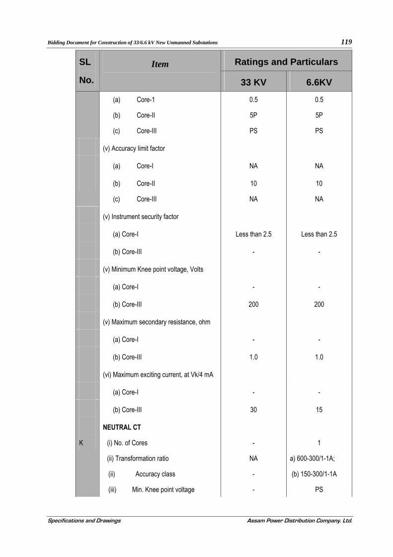
Bidding Document for Construction of 33/6.6 kV New Unmanned Substations 119
Specifications and Drawings Assam Power Distribution Company. Ltd.
SL
No.
Item Ratings and Particulars
33 KV 6.6KV
(a) Core-1
(b) Core-II
(c) Core-III
0.5
5P
PS
0.5
5P
PS
(v) Accuracy limit factor
(a) Core-I NA NA
(b) Core-II
(c) Core-III
10
NA
10
NA
(v) Instrument security factor
(a) Core-I Less than 2.5 Less than 2.5
(b) Core-III - -
(v) Minimum Knee point voltage, Volts
(a) Core-I - -
(b) Core-III 200 200
(v) Maximum secondary resistance, ohm
(a) Core-I - -
(b) Core-III 1.0 1.0
(vi) Maximum exciting current, at Vk/4 mA
(a) Core-I - -
(b) Core-III 30 15
K
NEUTRAL CT
(i) No. of Cores
(ii) Transformation ratio
(ii) Accuracy class
(iii) Min. Knee point voltage
-
NA
-
-
1
a) 600-300/1-1A;
(b) 150-300/1-1A
PS
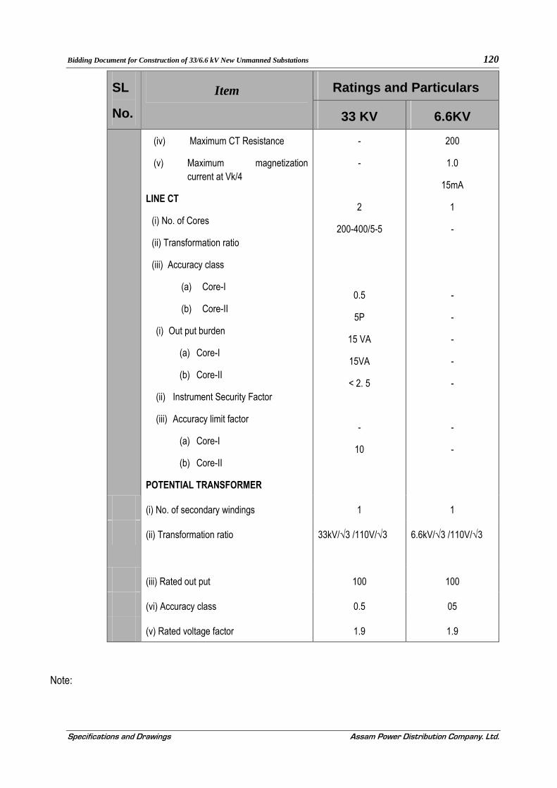
Bidding Document for Construction of 33/6.6 kV New Unmanned Substations 120
Specifications and Drawings Assam Power Distribution Company. Ltd.
SL
No.
Item Ratings and Particulars
33 KV 6.6KV
(iv) Maximum CT Resistance
(v) Maximum magnetization current at Vk/4
LINE CT
(i) No. of Cores
(ii) Transformation ratio
(iii) Accuracy class
(a) Core-I
(b) Core-II
(i) Out put burden
(a) Core-I
(b) Core-II
(ii) Instrument Security Factor
(iii) Accuracy limit factor
(a) Core-I
(b) Core-II
POTENTIAL TRANSFORMER
-
-
2
200-400/5-5
0.5
5P
15 VA
15VA
< 2. 5
-
10
200
1.0
15mA
1
-
-
-
-
-
-
-
-
(i) No. of secondary windings 1 1
(ii) Transformation ratio
33kV/√3 /110V/√3
6.6kV/√3 /110V/√3
(iii) Rated out put 100 100
(vi) Accuracy class 0.5 05
(v) Rated voltage factor 1.9 1.9
Note:

Bidding Document for Construction of 33/6.6 kV New Unmanned Substations 121
Specifications and Drawings Assam Power Distribution Company. Ltd.
(i) It is intended to use different ratios of the same CT at the same time for differential protections and metering cores. The CTS should therefore be suitable for the above purpose by secondary tapings only. The ratio change by secondary taps is acceptable as long as the required CT specifications are achieved at all ratios.
(ii) The knee point voltage specified above shall be at higher ratio/ taps.

Bidding Document for Construction of 33/6.6 kV New Unmanned Substations 122
Specifications and Drawings Assam Power Distribution Company. Ltd.
SECTION - 7
TECHNICAL SPECIFICATION FOR CONTROL AND RELAY PANELS
7.1.0. SCOPE
7.1.1. This Section is intended to cover the design, manufacture, assembly, testing at manufacturer’s works of Relay and Control Panels for Transformer Protection against Sadilapur & Panduport unmanned 33/6.6KV Substations.
7.1.2. The Control and Relay Panels required are for control and protection of the Power Transformers according to requirements. The supply shall include all accessories, special tools, supporting steels, spare parts, drawings, instruction manuals etc. The panels shall be supplied complete with all accessories as specified and completely assembled and all internal wiring completed.
7.1.3. All the sub-stations will be controlled from remote sub-station as well as local. The contractor has to supply the C&R panels to match the requirement
7.2.0. STANDARDS
7.2.1. All equipment and all component parts supplied under this specification shall conform in all respects to the latest issue of relevant Indian Standard Specifications except where specified otherwise in this specification. Equipment meeting any other authoritative standards which ensure an equal or better quality may also be acceptable.
7.3.0. TYPE OF PANEL
7.3.1. All panels shall be simplex type. One simplex panel shall be used for one transformer.
7.3.2. Simplex Control and Relay Panels shall consist of vertical fixed front panels with equipment mounted thereon and having wiring access from the rear. Each cubicle assembly shall be provided with doors on the rear having handles with built in locking facility. It shall have double leaf doors with lift off hinges at the back for panels of width more than 800 mm.
7.3.3. Equipment with control functions shall be provided on the front of the panels. Other equipment, if required may be provided on back of the panels (door mounted). All types of local communication ports of relays, meters etc. shall be accessible from front or without opening the panel door.
7.4.0. CONSTRUCTIONAL FEATURES
7.4.1. The panels shall be completely metal enclosed to ensure a dust, moisture and vermin proof atmosphere. The enclosure shall provide a degree of protection IP55.
7.4.2. Panels shall be rigid free standing and floor mounting type and comprise of structural frames enclosed completely with specially selected texture finished, cold rolled sheet steel of thickness not less than 3 mm for weight bearing members of the panels such as base frame, front sheet and door frames and not less than 2.5 mm for sides, door top and bottom portions. There shall be sufficient reinforcement to provide level surfaces, resistance to vibration and rigidity during transportation and installation.
7.4.3. All joints shall be made flush and all edges shall be bent at right angles and rounded. All structural members shall be bolted or welded together. Necessary arrangement shall be provided for bolting together the adjacent panels as well as for fastening them to the floor. The opening required for mounting the equipment shall be punched or cut and filed smooth.

Bidding Document for Construction of 33/6.6 kV New Unmanned Substations 123
Specifications and Drawings Assam Power Distribution Company. Ltd.
7.4.4. All doors, removable covers and panels shall be sealed all around with synthetic rubber gaskets Neoprene/EPDM generally conforming to provision of IS 11149. However, XLPE gaskets can also be used for fixing protective toughened glass doors. Ventilating louvers, if provided shall have screens and filters. The screens shall be made of either brass or GI wire mesh.
7.4.5. Panels shall have additional rolled channel plinth at the bottom with smooth bearing surface. The panels shall be fixed on the embedded foundation channels with intervening layers of anti-vibration strips made of shock absorbing materials which shall be supplied by the contractor.
7.5.0. MOUNTING OF EQUIPMENTS
7.5.1. All equipment on and in the panels shall be mounted and completely wired to the terminal blocks ready for external connection. All equipment on the front panels shall be mounted flush. Terminal markings shall be clearly visible.
7.6.0. INTERNAL WIRING
7.6.1. Panels shall be supplied completely with interconnecting wiring provided between all electrical devices mounted and wired in the panels and between the devices and terminal blocks for the devices to be connected to equipment outside the panels. When panels are located adjacent to each other all inter panel wiring and connections between the panels shall be furnished and wiring shall be carried out internally. These adjacent inter panel wiring shall be clearly indicated in the drawing furnished by the supplier.
7.6.2. Wiring shall be carried out with 1100-Volt grade, single core, stranded copper conductor wires with PVC insulation. The minimum size of stranded copper conductor used for internal wiring shall be as follows:
(a) All circuits except instrument transformers circuits: 2.5 sq. mm. per lead.
(b) Instrument transformers circuit: 4.0 sq. mm. per lead.
7.6.3. Auxiliary bus wiring for AC and DC supplies, voltage transformer circuits, annunciation circuits and other common services shall be provided near the top of the panel running throughout the entire length of the panels.
7.6.4. Wire terminals shall be made with solder less clamping type of tinned copper lugs, which firmly grip the conductor and insulation. Insulated sleeves shall be provided at all the wire terminations. Engraved core identification plastic ferrules marked to correspond with panel wiring diagram shall be fitted at both ends of each wire. Ferrules shall fit tightly on the wires and shall not fall off when the wire is disconnected from blocks.
7.6.5. Interconnections to adjacent panels shall be brought out to a separate set of terminals blocks located near the slots or holes meant for taking the interconnecting wires. Arrangement shall permit easy interconnection to adjacent panels at site and wires for this purpose shall be provided by the supplier looped and bunched properly inside the panel.
7.6.6. A laminated copy of total schematics is to be fixed on the inside of door.
7.7.0. TERMINAL BLOCKS
7.7.1. All internal wiring to be connected to the external equipment shall terminate on terminal blocks, preferably vertically mounted on the side of each panel. Terminal blocks shall be of 650 volts grade and have 10 amps continuous rating, moulded piece, complete with insulated barriers, stud type terminals, washers, nuts and lock nuts. Terminal block designs include a white fibre-marking strip with clear

Bidding Document for Construction of 33/6.6 kV New Unmanned Substations 124
Specifications and Drawings Assam Power Distribution Company. Ltd.
plastic/silicon chip on terminal covers. Marking on the terminal strips shall correspond to block and terminal number on the wiring diagram.
7.7.2. Terminal blocks for current transformer and voltage transformer secondary leads shall be provided with test links and isolating facilities. Current transformer secondary leads shall also be provided with short-circuiting and earthing facilities.
7.7.3. At least 20% spare terminals shall be provided on each panel and these terminals shall be uniformly distributed on all terminal blocks.
7.7.4. There shall be a minimum clearance of 250 mm between first row of terminal blocks and associated cable gland plates. Also, the clearance between two rows of terminal blocks shall be a minimum of 150 mm. A steel strip shall be connected between adjacent terminal block rows at 450-mm intervals for support of incoming cables.
7.8.0. PAINTING
7.8.1. All Sheet steelwork shall be phosphated in accordance with IS 6005.
7.8.2. Oil grease, dirt and warp shall be thoroughly removed by emulsion cleaning. Rust and scale shall be removed by pickling with dilute acid followed by washing with running water, rinsing with slightly alkaline hot water and drying.
7.8.3. After phosphating, thorough rinsing shall be carried out with clean water followed by final rinsing with dilute dichromate solution and oven drying. The phosphate coating shall be sealed with application of 2 (two) coats of ready mixed, stoving type zinc chromate primer. The first coat may be ‘flash dried’ while the second shall be stoved.
7.8.4. After application of the primer, two coats of finishing synthetic enamel paint shall be applied, each coat followed by stoving. The second finishing coat shall be applied after completion of tests. The Employer shall select the exterior colour of the paint at a later date.
7.8.5. Each coat of primer and finishing paint shall be of a slightly different shade to enable inspection of the painting.
7.8.6. The inside of the panels shall be glossy white.
7.8.7. A small quantity of finishing shall be supplied minor touching up required at site after installation.
7.9.0. NAME PLATES AND MARKINGS
7.9.1. All equipment mounted on front and rear side as well as equipment mounted inside the panel shall be provided with individual nameplates with equipment designation engraved. Also, on the top of the each panel on front as well as rear side large and bold name plates shall be provided for circuit /feeder designation.
7.9.2. All front mounted equipment shall be also provided at the rear with individual name plates engraved with Tag numbers corresponding to the one shown in the panel internal wiring to facilitate easy tracing of the wiring. The nameplates shall be mounted directly by the side of the respective equipment and shall not be hidden by the equipment wiring.
7.9.3. Nameplates shall be made of non-rusting metal or 3 ply lamicord. Nameplates shall be black with white engraved lettering.
7.10.0. MISCELLANEOUS ACCESSORIES

Bidding Document for Construction of 33/6.6 kV New Unmanned Substations 125
Specifications and Drawings Assam Power Distribution Company. Ltd.
7.10.1. A 240 Volts, single-phase plug points shall be provided in the interior of each cubicle with ON-OFF switch for connection of headlamp.
7.10.2. Each panel shall be provided with a fluorescent lighting fixtures for the interior illumination of the panel complete with all fittings, i.e. lamp, switch (controlled by panel door)
7.10.3. Each control panel shall be provided with necessary arrangements for receiving, distributing, isolating and fusing of D.C. and A.C. supplies of various control, signaling, lighting and space heater circuits. All fuses shall be HRC cartridge type mounted on plug - in type fuse bases. Fuses shall have operation indicators for indicating blown fuse condition. Fuse carrier base shall have imprints of the fuse rating and voltage. The main input A.C. and D.C. circuits will be protected with miniature circuit breakers.
7.11.0. EARTHING
7.11.1. All panels shall be equipped with an earth bus securely fixed along with inside base of the panels. The materials and the sizes of the bus bar shall be at least 25X4 mm copper. When several panels are mounted joining each other, the earth bus shall be made continuous and necessary connectors and clamps for this purpose shall be included in the scope of supply. Provisions shall be made for extending the earth bus bar to future adjoining panels on either side.
7.11.2. All metallic cases of equipment shall be connected to the earth bus by independent copper wires of size not less than 2.5 sq. mm. Earthing wire shall be connected on terminals with suitable clamp connectors and soldering shall not be permitted.
7.11.3. PT and CT secondary neutrals or common lead shall be earthed at one place only at the terminal blocks, where they enter the panels.
7.12.0. RECORDING METERS (TRIVECTOR METERS)
7.12.1. GENERAL
All meters shall be housed in dust proof, moisture resistant, black finished cases and shall be suitable for tropical use. They shall be accurately adjusted and calibrated at works and shall have means of calibration, check and adjustment at site.
All these instruments and meters shall be flush mounted type and back connected, suitable for panel mounting.
7.12.2. Principal Technical Parameters
The energy meters shall be indoor type connected with secondary side of outdoor CT and PT and shall be 3 phase 4 Wire type. The meters shall have the following parameters.
(a) Type of Installation : Flush /Rack mounted on Indoor Panel with back-connected terminals.
(b) Accuracy : 0.5 class
(c) Rated CT Secondary Current : 1 A
(d) Rated PT Secondary Voltage : 110/√3 Volts (phase to neutral)
(e) System Frequency : 50 Hz +/- 5%
(f) System Earthing : Solidly Earthed.

Bidding Document for Construction of 33/6.6 kV New Unmanned Substations 126
Specifications and Drawings Assam Power Distribution Company. Ltd.
(g) Communication Protocol : DLMS, MODBUS
7.12.3. GENERAL TECHNICAL REQUIREMENTS
7.12.3.1. POWER FACTOR RANGE
The meter shall be suitable for full power factor range from Zero (lag) to Unity to Zero (lead). The meters should work as an active energy import and export and reactive (lag and lead) energy measurement should be true four quadrants.
7.12.3.2. POWER SUPPLY VARIATION
The extreme power supply variation (which an operating meter should withstand without damage and without degradation of its meteorological characteristics when it is subsequently operated under its operating conditions) is as follows.
Voltage : 60% to 120 % of V ref
Frequency : 50 Hz ± 5%
The bidder can also offer meters which can withstand higher variations.
7.12.3.3. ACCURACY
The class of accuracy of the meter shall be 0.5.
7.12.3.4. POWER CONSUMPTION
The active and apparent power consumption on each voltage circuit including power supply of the meter at ref. Voltage, temperature and frequency shall not exceed the limits as per IS: 14697
The apparent power drawn by each current circuit of the meter shall not exceed as per IS 146971 of basic current, reference frequency and reference temperature
7.12.3.5. STARTING CURRENT
The meter shall start registering energy at 0.1% of basic current at unity power factor.
When the voltage is applied with no current flowing in the current circuit, the meter shall not register any energy and the test output of the meter shall not be more than 1 pulse per count on no load.
7.12.3.6. MAXIMUM CONTINUOUS CURRENT
The maximum continuous current in meters shall be 120% of rated basic current (Ib) at which the meter purports to meet the accuracy requirements as per the relevant standards.
7.12.3.7. CONNECTIONS
The meters shall be suitable for being connected directly through its terminal block to
a. Secondary of Voltage Transformers, and
b. Secondary of Current Transformers.
7.12.3.8. TEST TERMINAL BLOCK

Bidding Document for Construction of 33/6.6 kV New Unmanned Substations 127
Specifications and Drawings Assam Power Distribution Company. Ltd.
The meter shall be provided with a test blocks for testing without disturbing the CT and PT secondary connections. Meter shall have digital display.
7.12.4. GENERAL & CONSTRUCTIONAL REQUIREMENTS
7.12.4.1. General
The meter should be housed in a safe, high grade engineering plastic / polycarbonate casing, and is dust/moisture proof, conforming to IP-51 of BIS 12063 / IEC 529, vermin proof and sturdy.
7.12.4.2. Terminal Block
The terminal block shall be made out of high grade non-hygroscopic, low tracking, properly fire resistant, reinforced high grade engineering plastic and designed according to adequate rating requirement conforming to relevant standards and having provision for sealing.
7.12.4.3. Sealing of Meter
Reliable sealing arrangement should be provided to make the meter tamper proof and avoid fiddling or tampering by unauthorized persons.
7.12.4.4. Name-Plate Marking of the Meter
Meters shall have a name plate clearly visible and effectively secured against removal, indelibly and distinctly marked with all essential particulars as per relevant Standards.
7.12.5. Quantities to be Measured
The meter shall be capable of measuring and displaying the below mentioned electrical quantities within specified accuracy limits for poly-phase balanced or unbalanced loads at all power factors.
The measurements shall be carried out on 3 phase, 4 wire principle within an accuracy as per 0.5 class of IS: 14697.
(i) Active energy measurement in all four quadrants (import / export at all power factors). The meter shall compute the active energy, reactive energy, apparent energy and store it in its memory.
(ii) The meter shall continuously display the average of the RMS values of the three line to neutral PT secondary voltages as a percentage of 63.5 volts, and display the same on demand.
(iii) The meters shall be able to measure & display the instantaneous voltages and currents for all three phases instantaneous average three phase power, instantaneous and average power factor. The meter shall be suitable for working under balanced / unbalanced loads at all power factor (i.e. zero lag-unity-zero lead).
(iv) The meters shall measure and display cumulative active energy, apparent energy, reactive (lag) energy, reactive (lead) energy in both import and export mode.
(v) The meter shall also store the apparent energy (import & export) and cumulative energy registers of the same shall be made available on display.
(vi) The three line to neutral voltages shall be continuously monitored and an indication shall be provided on the display for healthiness of the same. In case any of these falls below about 60 %, the same shall be indicated on the display. The time blocks in which such a voltage failure occurs / persists shall also be recorded in the meter’s memory. The reactive energy registers specified in Para (viii) above shall remain stay put while PT supply is unhealthy.

Bidding Document for Construction of 33/6.6 kV New Unmanned Substations 128
Specifications and Drawings Assam Power Distribution Company. Ltd.
(vii) The meters shall compute the maximum demand of Apparent Power with programmable integration period of 15/30 minutes for both import and export.
(viii) The meters shall also compute power-on hours based on the duration for which at least one phase supply was available to the meter.
(ix) The meter shall be compatible with Availability Based Tariff, two part as well as TOD tariff. For TOD tariff, the meter shall have the provision to define maximum 8 TOD registers for different energies.
(x) The meters should measure fundamental energy.
(xi) The meter should record calendar month wise active energy, apparent & reactive energy and should display automatically in the next calendar month.
(xii) The meter should indicate monthly average PF for calendar month and should display on demand.
7.12.6. Quantities to be Displayed
The meter shall display the required parameters in two different modes as follows:
a) Auto Display Mode
Meter Identification Code
Display test (LCD/LED Segment check)
Real time & date
Cumulative Active Energy , apparent & reactive energy for Import/export mode
Monthly Average PF
Percentage of average of three RMS voltage with respect to normal system voltage.
Instantaneous average 3 φ PF
Instantaneous frequency
Instantaneous Phase voltages R,Y,B
Instantaneous Phase currents R,Y,B
Instantaneous Active Power
Instantaneous Reactive Power
Instantaneous Apparent Power
Current month Maximum Demand kVA Import
Current month Maximum Demand kVA Export
Previous month Maximum Demand kVA Import
Previous month Maximum Demand kVA Export

Bidding Document for Construction of 33/6.6 kV New Unmanned Substations 129
Specifications and Drawings Assam Power Distribution Company. Ltd.
Power-ON Hours
b) Manual display Mode:
TOD Cumulative Active Energy Import/export
Cumulative apparent Energy Export
Cumulative Reactive Energy Import/export
Cumulative Maximum Demand kVA/KW
TOD maximum demand
Monthly average power factor
Phase Sequence-Voltage
Tamper informations
7.12.7. Load Survey Capability
7.12.7.1. Load survey shall be available for at least 60 days for the following parameters
i) kWh exported
ii) kwh imported
iii) kVAh exported
iv) kVAh imported
v) Voltage profile
vi) Average Frequency
vii) Monthly maximum demand
viii) TOD maximum demand
7.12.7.2. The load survey data, abnormality event information and instantaneous parameters data shall all be retrievable through the meter's communication port from a common meter-reading instrument (CMRI).
7.12.7.3. The meter shall have sufficient non-volatile memory for recording history of energy parameters for atleast last 60 days.
7.12.8. Remote Readout Facility, Communication Capability
7.12.8.1. The meter shall be DLMS compitable.
7.12.8.2. The meter shall be provided with a galvanically isolated optical communication port as per IEC 1107, PACT, ANSI with removable cover and with hardware locking arrangement so that it can be easily connected to a CMRI (Common Meter Reading Instrument) / laptop for data. The optical communication port shall also have sealing provision.
7.12.8.3. The meter shall have a communication port for transferring the data to the local, remote and SCADA. The metering system port/ports should also support on-demand local /remote data acquisition of load survey and parameters from the meters. These ports should support OFC for data transfer with time synchronization. Simultaneous transfer of on-line and on-demand metering data should be possible.

Bidding Document for Construction of 33/6.6 kV New Unmanned Substations 130
Specifications and Drawings Assam Power Distribution Company. Ltd.
7.12.8.4. The meter shall be capable of data transmission to RTU as well. It shall be responsibility of the bidder to ensure that meters shall be compatible to the RTUs. For this bidder should note that RTUs support IEC 60870-5-101, IEC 60870-5-103, Modbus protocols.
7.12.9. Calibration and Test Output
7.12.9.1. The meter should have test output accessible from the front and be capable of being monitored with suitable testing equipment. The operation indicator must be visible from the front. Test output device shall be provided in the form of one common LED for KWh, KVARh and KVAh with provision of selecting the parameter being tested.
7.12.9.2. The test output device should have constant pulse rate in terms of pulse/unit energy and its value should be indelibly printed on the rating plate.
7.12.9.3. The device shall be suitable for use with sensing probe used with test benches or reference standards.
7.12.10. Display
7.12.10.1. The meter shall have a minimum 7 digit backlit liquid crystal display (LCD) with another digit for legend. The minimum character height shall be 5 mm.
7.12.10.2. The meter should have facility of auto display mode where all parameters automatically scroll within the specified time and a manual mode where the parameters can be read by push button operation. In auto display mode each parameter shall on display for 10 seconds.
7.12.11. Real Time Clock
7.12.11.1. A real time quartz clock shall be used in the meter for maintaining time and calendar date. The maximum drift shall not exceed -/+ 180 seconds per year. The uncertainty of setting initial time shall not exceed + 30 Seconds with respect to Indian standard time.
7.12.11.2. Facility for adjustment of real time shall be provided through CMRI/Work station with proper security.
7.12.11.3. It shall also be possible to synchronise clocks of all the meters through GPS clock. All necessary equipment shall be provided to run the auto time synchronization of all energy meters through a locally located GPS clock available in each sub-station.
7.12.12. Memory
7.12.12.1. The meter shall have non-volatile memory, so that the registered parameters will not be affected by loss of power. The non-volatile memory should have a minimum retention time of 10 years.
7.12.13. Harmonics Measurement
7.12.13.1. THD Upto 29 th Harmonic shall be measurable that is a sampling rate of 3000/sec. The meter should be capable of measuring fundamental energy as well as total energy. Fundamental energy shall be made available on meter-display and the same only shall be used for billing purpose.
7.12.14. Self-Diagnostic Feature
7.12.14.1. The meter shall be capable of performing complete self-diagnostic check to monitor the circuits for any malfunctioning to ensure integrity of data memory location at all times. The meter shall have indications for unsatisfactory/non-functioning/malfunctioning of the following:
a) Real Time and Date
b) All display segments as per the requirement
c) Non-volatile memory (NVM) failure indication at SAS

Bidding Document for Construction of 33/6.6 kV New Unmanned Substations 131
Specifications and Drawings Assam Power Distribution Company. Ltd.
d) Low battery indication at SAS
7.12.14.2. While installing the meter, it should be possible to check the correctness of Current Transformer, Voltage connections to the meter and their polarity from the functioning of the meter for different voltage injections with the help of vector/phasor diagrams. For this purpose suitable software for field diagnosis of meter connections with the help of Meter Reading Instrument should be supplied.
7.12.15. Anomaly Detection Features
7.12.15.1. There shall be an appropriate display system by which any attempt of tampering the meter is promptly displayed with date and time tagging. It shall be able to display the following information about tampering events that have occurred since demand reset
7.12.15.2. The meters shall have features to detect the occurrence and restoration of, at least, the following common temper / anomaly
a) Missing Potential: The meter shall be capable of detecting and recording occurrence and restoration with date and time the cases of Potential failure which could happen due to accidental / intentional disconnection of potential leads (one or two).
b) CT Polarity Reversal: The meter shall be capable of detecting and recording occurrences and restoration of CT polarity reversal of one or more phases.
c) Current and Potential Imbalance: The meter shall be capable of detecting and recording occurrences and restoration of unbalance of voltage and current.
Snapshots of voltage, current, power factor and energy (active) readings as well as date and time of occurrences and restoration of all anomaly events shall be logged into the meter memory and available for retrieving through the meter’s optical port and down loading to SAS
d) Power on/off: The meter shall be capable to record power on /off events in the meter memory. All potential failure should be record as power off event.
7.12.15.3. Last 200 such events in total with date and time shall be stored in the meter memory on first in first out basis.
7.12.16. Common Meter Reading Instruments / Laptop
7.12.16.1. Up loading and down loading of meter data through optical port should be possible by Common Meter Reading Instruments (CMRI) as well as Laptop
7.12.16.2. Supply of Common Meter Reading Instruments (CMRI) or Laptop is not in the scope of the bidder. These will be made available at site by the Employer. However, any inter face cable/ converter is required, the bidder shall supply the same free of charge.
7.12.17. Software for Monitoring
7.12.17.1. The online monitoring software of sub-station automation system shall acquire the real time data of the energy meters.
7.12.17.2. Energy meter off line communication software (for CMRI and Laptop interface) shall be compatible with Vista/ Windows XP
7.13.0. RELAYS
7.13.1. GENERAL
Bidding Document for Construction of 33/6.6 kV New Unmanned Substations 132
Specifications and Drawings Assam Power Distribution Company. Ltd.
7.13.1.1. All relays shall conform to the requirements of IS 3231/IEC 60255/ IEC 61000 or other relevant standards.
7.13.1.2. All protective relays shall be numerical type with open communication protocol.
7.13.1.3. Relay should have the compatibility to communicate with local control as well as SCADA.
7.13.1.4. Relays shall be suitable for flush or semi-flush mounting with connectors from rear.
7.13.1.5. All draw out cases or plug in type modular cases will have proper testing facilities. The testing facilities provided on the relays shall be specifically stated in the bid. Necessary test plug shall be in the supplier's scope of supply and shall be supplied loose. Unless otherwise specified all auxiliary relays and timers shall be supplied either in non-draw out cases or plug in type modular cases.
7.13.1.6. All A.C. relays shall be suitable for operation at 50 Hz. A.C.. DC auxiliary relays and timers shall be designed for 48 volts DC and shall operate satisfactorily between 70% and 110% of rated voltage.
7.13.1.7. All Protective relays, auxiliary relays and timers except the lockout relays and interlocking relays shall be provided with self reset type contacts. All protective relays, trip relays and timers shall be provided with externally reset positive action operation indicators provided with proper inscription. All protective relays which do not have built-in hand reset operation indicators shall have additional auxiliary relays with operating indicators for this purpose. Similar separate operating indicators (auxiliary relays) shall also be provided in the trip circuits of protections located outside the board such as Buchholz relays, temperature protection etc.
7.13.1.8. No control relays that shall trip the circuit breaker when the relays are de-energized shall be employed in the circuits.
7.13.1.9. All relays shall withstand a test voltage of 2.5 kV, 50 Hz r.m.s. voltage for one second.
7.13.1.10. Auxiliary seal-in unit provided in the protective relays shall preferably be of shunt reinforcement type. If series relays are used the following shall be strictly ensured:
(i) The operating time of the series seal-in unit shall be sufficiently shorter than that of the trip coil
relay in series with which it operates to ensure definite operation of the flag indicator of the relay.
(ii) Seal - in unit shall obtain adequate current for operation when one or more relays operate
simultaneously.
(iii) Impedance of the seal-in unit shall be small enough to permit satisfactory operation of the trip coil
on trip relays when D.C. supply is minimum.
7.13.1.11. All protective relays and alarm relays shall be provided with one extra isolated pair of contacts wired terminals exclusively for Employer’s use.
7.13.2. GENERAL SPECIFICATION OF NUMERICAL RELAYS
7.13.2.1. Numerical Relays shall be provided for the following applications :
Integrated Numerical Transformer Protection
Back up non directional over current (3 O/C) and earth fault relays with high set units for power transformers
7.13.2.2. All Numerical Relays should have following minimum features.

Bidding Document for Construction of 33/6.6 kV New Unmanned Substations 133
Specifications and Drawings Assam Power Distribution Company. Ltd.
Relays shall be communicable on open protocol without any protocol converter.
Relays shall have one no. front RJ45 or USB port for Local Relay Parameterization and One no. rear FO port/ Rear RS485 for connectivity to remote monitoring
The relay shall have sufficient battery back up to keep the internal clock running for at least 2 years in absence of auxiliary supply
Should have minimum 12 configurable LEDs
Should have minimum 16 Binary Inputs and 24 Binary Outputs
All BI/BOs shall be configurable
Shall have front minimum 4 lines LCD display with Alpha numeric key pad
Numerical relays are provided with built in Event / Disturbance / Fault Recorder features.
The bidder shall bring out in the bid that the Numerical relays providing different protection features / application in a single unit if any one of the application/feature goes out of service the other feature/application (s) will remain un-effected.
The relays shall be site configurable (Including logic development)
Configured features & set values shall be in non volatile memory
Must have real time clock for time stamping of events/ disturbances with time synchronization inputs (GPRS etc.)
The relays should have self-diagnostic features identifying area of fault or failure of a particular component or card.
7.13.2.3. Hardware based measurement shall not be acceptable.
7.13.2.4. The relay should have high immunity to electrical and electromagnetic interference.
7.13.2.5. The same relay shall be provided with both 1A and 5A CT inputs and shall be site selectable.
7.13.2.6. It shall be possible to energise the relay from either AC or DC auxiliary supply. Auxiliary dc supply shall be suitable for both 48 Volt and shall be site selectable.
7.13.2.7. Be capable of performing basic instrumentation functions and displaying various instantaneous parameters like Voltage, current, active power, reactive power etc. in primary values. Additionally all sequence current and voltage values shall be displayed on-line. Also the direction of power flow shall be displayed.
7.13.2.8. Extensive disturbance recording facility shall be available for at least up to 10 seconds to capture maximum possible information. Necessary software shall be provided for retrieving and analysing the records.
8.12.4.0. Facility for developing customised logic schemes inside the relay based on Boolean logic gates and timers should be available. Facility for renaming the menu texts as required by operating staff at site should be provided.
7.13.2.9. Must have additional feature of local breaker back up protection
The relay shall have built in Circuit Breaker Supervision Functions

Bidding Document for Construction of 33/6.6 kV New Unmanned Substations 134
Specifications and Drawings Assam Power Distribution Company. Ltd.
The relay shall be able to detect any discrepancy found between NO & NC contacts of breaker
The relay shall monitor number of breaker trip operations
The relay shall also monitor the breaker operating time
7.13.2.10. The relays shall have the following tools for fault diagnostics
Fault record – The relay shall have the facility to store fault records with information on cause of trip, date, time, trip values of electrical parameters.
Event record – The relay shall have the facility to store time stamped event records with 1ms resolution.
Disturbance records – The relay shall have capacity to store disturbance records of at least 10 sec. duration.
It shall be possible to preserve stored information in the event of an auxiliary supply failure with the help of a battery back up.
The relay settings shall be provided with password protection.
It shall be possible to change the relay setting from the front panel using the key pads/ /Laptop.
7.13.2.11. The relay shall have comprehensive self-diagnostic feature. This feature shall continuously monitor the healthiness of all the hardware and software elements of the relay. Any failure detected shall be annunciated through an output watchdog contact. The fault diagnosis information shall be displayed on the LCD. These records shall also be retrieved from local as well as remote terminal through the communication port.
7.13.2.12. The Numerical Relays shall be provided with 1 set of common support software compatible with Windows XP, Windows-7 which will allow easy settings of relays in addition to uploading of event, fault, disturbance records, and measurements. The relay settings shall also be changed from local or remote using the same software.
7.13.3. INTEGRATED NUMERICAL TRANSFORMER PROTECTION RELAY
7.13.3.1. General requirements
a) Shall be stable during magnetising inrush and over fluxing conditions. Stabilization under inrush conditions shall be based on the presence of second harmonic components in the differential currents.
b) Shall have saturation discriminator as an additional safeguard for stability under through fault conditions.
c) Shall have zero sequence current filtering, which may be deactivated separately for each winding, for special applications.
d) Shall have software to take care of the angle & ratio correction of CT inputs.
e) Shall have all output relays suitable for both signals and trip duties
7.13.3.2. Functional Descriptions

Bidding Document for Construction of 33/6.6 kV New Unmanned Substations 135
Specifications and Drawings Assam Power Distribution Company. Ltd.
The integrated Numerical Transformer Protection Scheme shall have following functional qualities: -
a) Differential protection
The relay shall be biased differential protection with triple slope tripping characteristics with faulty phase identification / indication. The range for the differential pick-up shall be from 0.1 to 2.5 p.u. Its operating time shall not exceed 30 ms at 5 times rated current.
The relay shall have two adjustable bias slopes from 20 % to 150 % and slope from 40% to 150 %, to provide maximum sensitivity for internal faults with high stability for through faults
The relay shall have an unrestrained high set element to back up the biased differential function and the setting range for it shall have a minimum setting of 5pu and a maximum setting of 30pu.
The relay shall have the second harmonic restraint feature for stability under transformer inrush condition. The setting shall be 15-25%.
Further, the fifth harmonic blocking for stability under transient over fluxing condition shall be provided.
b) Restricted Earth fault Protection
The scheme shall have in-built restricted earth Fault (REF) for the LV winding. This function should be provided to maximise the sensitivity of the protection of earth faults. The REF function should be a high impedance element. The REF function should be able to share Current Transformers with the biased differential function. As in traditional REF protections, the function should respond only to the fundamental frequency component of the currents.
c) Thermal Overload Protection
Shall have two stages of thermal overload protection for alarm and trip condition with continuously adjustable setting range of 100-400% of rated current and time constant setting range of 1.0 to 1000.0 min continuously.
Shall be single pole type.
Shall have a drop off/pick up ratio greater than 95%
Shall have separately adjustable time delay relays for alarm having a setting range of 1to 10 seconds continuously
d) Over Current Protection
The relay shall have three stages of definite time over current protection as backup operating with separate measuring systems for the evaluation of the three phase currents, the negative sequence current and the residual current.
In addition, the relay shall have three stages of Inverse time over current protection operating based on one measuring system each for the three phase currents, the negative sequence current and the residual current.
e) Shall have additional features to provide under frequency protection.
7.13.4. OVER CURRENT AND EARTH FAULT RELAYS

Bidding Document for Construction of 33/6.6 kV New Unmanned Substations 136
Specifications and Drawings Assam Power Distribution Company. Ltd.
7.13.4.1. These relays shall be of numeric, single/multi pole, directional /non-directional type with or without high set element as specified. These relays shall have the following features/characteristics:
(i). IDMT characteristic with definite minimum time of 3 second at 10 times setting.
(ii). Other operating curves such as inverse, very inverse shall be selectable
(iii). Adjustable setting range of 50-200 % and 20-80% of rated current for over current and earth fault relays respectively.
(iv). Must have faulty phase, type of fault identification
(v). Shall be draw out type
7.13.5. TRIP CIRCUIT SUPERVISION RELAY
7.13.5.1. The relay shall be capable of monitoring the healthiness of each 'phase' trip-coil and associated circuit of circuit breaker during 'ON' and 'OFF' conditions.
7.13.5.2. The relay shall have adequate contacts for providing connection to alarm and event logger.
7.13.5.3. The relay shall have time delay on drop-off of not less than 200 milli seconds and be provided with operation indications for each phase.
7.13.6. MASTER TRIP RELAY
7.13.6.1. High Speed Tripping Relay shall be instantaneous (operating time not to exceed 10 milli-seconds
7.13.6.2. The relays shall reset within 20 milli seconds
7.13.6.3. The relays shall be D.C. operated
7.13.6.4. The relays shall have adequate contacts to meet the requirement of scheme, other functions like auto-reclose relay, LBB relay as well as cater to associated equipment like event logger, Disturbance recorder, fault Locator, etc.
7.13.6.5. The relays shall be provided with operation indicators for each element/coil.
7.13.7. OTHER TRIP RELAYS
7.13.7.1. For transformer protection other trip relays for Buchholz, winding & oil temperature high, PRD etc. shall be provided as per requirement.
7.13.7.2. These High Speed Tripping Relays shall be instantaneous (operating time not to exceed 10 milli-seconds
7.13.7.3. The relays shall have adequate contacts to meet the requirement of scheme
7.13.8. DC SUPPLY SUPERVISION RELAY
7.13.8.1. The relay shall be capable of monitoring the failure of D.C. supply to which, it is connected.
7.13.8.2. It shall have adequate potential free contacts to meet the scheme requirement.
7.13.8.3. The relay shall have a 'time delay on drop-off' of not less than 100 milli seconds and
7.13.8.4. The relays shall be provided with operation indicator/flag.
7.14.0. PROTECTION SCHEME FOR PANELS
The following protections scheme shall be provided for Panels for all Power and Auto Transformers:

Bidding Document for Construction of 33/6.6 kV New Unmanned Substations 137
Specifications and Drawings Assam Power Distribution Company. Ltd.
(a) Main Protection
Biased transformer differential protection employing relay type specified in Clause 7.13.3. The
scheme shall include also following:
(i) Second and fifth harmonic restraint feature.
(ii) The relay shall also provide Restricted Earth Fault Protection.
(iii) The scheme shall have suitable input and output for transformer auxiliary protection like Buchholz, oil temperature, winding temperature etc.
(b) Backup Protection
The backup protection shall be provided with non-directional relays as specified in Clause 7.13.4. One triple pole over current relays for phase faults and one Earth Fault Relay for Earth Faults with high set elements shall be provided. The high set unit should not operate due to transformer in-rush current.
7.15.0. TESTS
7.15.1. The supplier shall carryout all tests as per relevant standards as all associated equipment including relays, meters, instruments etc. The supplier shall submit all that reports to Employer for approval before despatching the control and relay panels. The Bidder shall also submit along with the bid type test reports for relays instruments, meters and other devices of the type and class being offered.
7.15.2. Control and relay panels shall be subjected to the following tests:
a. Mechanical operation test.
b. Verification of degree of protection.
c. High voltage test (2000 volts for 1 minute)
d. Electrical control interlock and sequential operation test.
e. Verification of wiring as per approved schematic.
7.16.0. PRE-COMMISSIONING TESTS
7.16.1. The contractor shall have to perform following minimum Pre-commissioning tests for commissioning of the C&R panels. For this purpose, the contractor shall arrange all required tools and testing equipment at site
(i). IR values of all circuits
(ii). Measurement of burden in CT & PT circuits
(iii). Primary current injection of CT circuits with connected burden
(iv). Energisation of PTs at suitable low voltage and measurement of PT inputs at all measuring points

Bidding Document for Construction of 33/6.6 kV New Unmanned Substations 138
Specifications and Drawings Assam Power Distribution Company. Ltd.
(v). Secondary ac current injection of relays, dynamic testing of all numeric relays. Tracing of zone curves, limits. Checking of relay timings, inherent or set values. For this testing, the contractor shall bring ‘Omicron’ or equivalent test kit.
(vi). Testing of voltage related elements like directional element, over fluxing, over/ under frequency, over/ under voltage features, tracing of curves and checking limits of set values and associated timings
(vii). Checking of Boolean logic gates, BI/BO points of the numeric relays, checking conformity to specification and checking of set logics
(viii). Checking of stability and sensitivity of differential zones by suitably applying 3-phase low voltages and shorting of primary circuits. Measurements of voltage and current inputs to all relays.
(ix). Checking stability & sensitivity of bus differential relay zones by suitably injecting current
(x). Checking registration of event and disturbance records in the numeric relays and down loading
(xi). Testing of AR schemes
(xii). Checking of healthiness of each dc circuit of panels
(xiii). Simulation of faults like Buchholz, OTI, WTI and other relays and checking of tripping of breaker and connected annunciation
(xiv). Operation of master trip relays, tripping of breaker through each trip coil and checking of inter locks
(xv). Simulation of faults like low gas, and checking operation of inter locks.
7.17.0. TECHNICAL DATA SHEET FOR THE RELAY AND CONTROL PANELS
7.17.1. Features to be provided in various Relay and Control panel are indicated below. Description below are only indicative; the Contractor shall ensure that all items are included in their offer to complete the schemes described in the Specification whether such items are specifically mentioned or not.
7.17.2. Transformer Panels
SL
NO
ITEM RATINGS AND PARTICULARS
33/6.6 kV Transformer Panel
TRANSFORMER PANELS
1 Protection and Relays:
(a) Differential Protection as per Clause 7.13.3 1 No.

Bidding Document for Construction of 33/6.6 kV New Unmanned Substations 139
Specifications and Drawings Assam Power Distribution Company. Ltd.
SL
NO
ITEM RATINGS AND PARTICULARS
33/6.6 kV Transformer Panel
(b) Back up non-directional over current scheme for HV side as per Clause 7.13.4
1 Set
(c) Back up non-directional over current and earth fault scheme for LV Side as per Clause 7.13.4
1 Set
(d) Trip Circuit Supervision Relay Scheme for ascertaining pre and post-closing healthiness
Supervision for 4 trip coils (2 trip coils per breaker on each
side)
(e) DC Supply healthy monitoring scheme 1 No.
(f) AC Supply healthy monitoring scheme 1 No.
(j) Tripping relay for Bucholtz, PRD, WTI, OTI etc. As required
(k) Alarm auxiliary for Bucholtz, PRD, WTI, OTI, MOG etc.
As required
(l) Transformer tap position status/ raise & lower 1
2
Meters
(a) Tri-vector Meter as per Clause 7.13.0. 1Nos. (on 6.6 kV side) for each transformer
(b) For 33 KV feeders 2Nos.
3 Controls / interlocks / Status indication/ Annunciation
4 For Capacitor bank:
(a) Numeric IDMTL relay with Over current and Earth fault function
1 for each bank
(b) Over voltage relay 1 for each bank
NOTE:
1. The tabled items are general and indicative
2. The bidder will match equipment requirement as per detailed engineering. Any improved proposal without compromising on protection and control shall be considered.

Bidding Document for Construction of 33/6.6 kV New Un-Manned Substations 140
Specifications and Drawings Assam Power Distribution Company Ltd.
SECTION -8
TECHNICAL SPECIFICATION OF ISOLATORS
8.1.0. SCOPE
8.1.1. This section of the specification is intended to cover design specifications for manufacture and testing of 33 KV and 6.6 KV gang operated switch (Isolators) with all fittings and accessories.
8.1.2. The Isolators are for outdoor installation suitable for horizontale/vertical mounting on pole/mounting structures and for use at sub-stations.
8.1.3. Isolators shall be supplied with Earth Switch as and where specified.
8.2.0. GENERAL
8.2.1. The Isolators and accessories shall conform in general to IS 9921 (or IEC: 62271-102) except to the extent explicitly modified in specification.
8.2.2. All isolating switches and earthing switches shall have rotating blades and pressure releasing contacts. All isolating and earth switches shall operate through 90° from closed position to fully open position.
8.2.3. Complete isolator with all the necessary items for successful operation shall be supplied including but not limited to the following:
(i). Isolator assembled with complete base frame, linkages, operating mechanism, control cabinet, interlocks etc.
(ii). All necessary parts to provide a complete and operable isolator installation, control parts and other devices whether specifically called for herein or not.
(iii). The isolator shall be designed for use in the geographic and meteorological conditions as given in Section 1.
8.3.0. DUTY REQUIREMENTS
8.3.1. Isolators and earth switches shall be capable of withstanding the dynamic and thermal effects of the maximum possible short circuit current of the systems in their closed position. They shall be constructed such that they do not open under influence of short circuit current.
8.3.2. The earth switches, wherever provided, shall be constructionally interlocked so that the earth switches can be operated only when the isolator is open and vice versa. The constructional interlocks shall be built in construction of isolator and shall be in addition to the electrical and mechanical interlocks provided in the operating mechanism.
8.3.3. In addition to the constructional interlock, isolator and earth switches shall have provision to prevent their electrical and manual operation unless the associated and other interlocking conditions are met. All these interlocks shall be of failsafe type. Suitable individual interlocking coil arrangements shall be provided. The interlocking coil shall be suitable for continuous operation from DC supply and within a variation range as stipulated elsewhere in this specification.

Bidding Document for Construction of 33/6.6 kV New Un-Manned Substations 141
Specifications and Drawings Assam Power Distribution Company Ltd.
8.3.4. The earthing switches shall be capable of discharging trapped charges of the associated lines.
8.3.5. The isolator shall be capable of making/breaking normal currents when no significant change in voltage occurs across the terminals of each pole of isolator on account of make/break operation.
8.3.6. The isolator shall be capable of making/breaking magnetising current of 0.7A at 0.15 power factor and capacitive current of 0.7A at 0.15 power factor at rated voltage.
8.4.0. CONSTRUCTIONAL DETAILS
8.4.1. All isolating switches and earthing switches shall have rotating blades and pressure releasing contacts. All isolating and earth switches shall operate through 90° angle from closed position to fully open position.
8.4.2. Contacts:
a) The contacts shall be self-aligning and self-cleaning and so designed that binding cannot occur after remaining closed for prolonged periods of time in a heavily polluted atmosphere.
b) No undue wear or scuffing shall be evident during the mechanical endurance tests. Contacts and spring shall be designed so that readjustments in contact pressure shall not be necessary throughout the life of the isolator or earthing switch. Each contact or pair of contacts shall be independently sprung so that full pressure is maintained on all contacts at all time.
c) Contact springs shall not carry any current and shall not lose their characteristics due to heating effects.
d) The moving contact of double break isolator shall have turn-and -twist type or other suitable type of locking arrangement to ensure adequate contact pressure.
8.4.3. Blades:
a) All metal parts shall be of non-rusting and non-corroding material. All current carrying parts shall be made from high conductivity electrolytic copper/aluminium. Bolts, screws and pins shall be provided with lock washers. Keys or equivalent locking facilities if provided on current carrying parts, shall be made of copper silicon alloy or stainless steel or equivalent. The bolts or pins used in current carrying parts shall be made of non-corroding material. All ferrous castings except current carrying parts shall be made of malleable cast iron or cast-steel. No grey iron shall be used in the manufacture of any part of the isolator.
b) The live parts shall be designed to eliminate sharp joints, edges and other corona producing surfaces, where this is impracticable adequate corona shield shall be provided..
c) Isolators and earthing switches including their operating parts shall be such that they cannot be dislodged from their open or closed positions by short circuit forces, gravity, wind pressure, vibrations, shocks, or accidental touching of the connecting rods of the operating mechanism.
d) The switch shall be designed such that no lubrication of any part is required except at very infrequent intervals i.e. after every 1000 operations or after 5 years whichever is earlier.
8.4.4. Insulators:
a) The insulator shall conform to IS: 2544 and/or IEC-60168. The insulators shall have a minimum cantilever strength of 400 Kgs. for 33/11 kV insulators respectively.

Bidding Document for Construction of 33/6.6 kV New Un-Manned Substations 142
Specifications and Drawings Assam Power Distribution Company Ltd.
b) Pressure due to the contact shall not be transferred to the insulators after the main blades are fully closed.
8.4.5. Base:
Each isolator shall be provided with a complete galvanised steel base provided with holes and designed for mounting on a supporting structure.
8.5.0. EARTHING SWITCHES
8.5.1. Where earthing switches are specified these shall include the complete operating mechanism and auxiliary contacts.
8.5.2. The earthing switches shall form an integral part of the isolator and shall be mounted on the base frame of the isolator.
8.5.3. The earthing switches shall be constructionally interlocked with the isolator so that the earthing switches can be operated only when the isolator is open and vice versa. The constructional interlocks shall be built in construction of isolator and shall be in addition to the electrical interlocks.
Suitable mechanical arrangement shall be provided for de-linking electrical drive for mechanical operation.
8.5.4. Each earth switch shall be provided with flexible copper/aluminum braids for connection to earth terminal. These braids shall have the same short time current carrying capacity as the earth blade. The transfer of fault current through swivel connection will not be accepted.
8.5.5. The frame of each isolator and earthing switches shall be provided with two reliable earth terminals for connection to the earth mat.
8.5.6. Isolator design shall be such as to permit addition of earth switches at a future date. It should be possible to interchange position of earth switch to either side.
8.5.7. The earth switch should be able to carry the same fault current as the main blades of the Isolators and shall withstand dynamic stresses.
8.6.0. OPERATING MECHANISM
8.6.1. The bidder shall offer manual operated Isolators and earth switches..
8.6.2. Control cabinet/operating mechanism box shall be made of aluminum sheet of adequate thickness (minimum 3 mm).
8.6.3. Gear should be of forged material suitably chosen to avoid bending/jamming on operation after a prolonged period of non-operation. Also all gear and connected material should be so chosen/surface treated to avoid rusting.
8.7.0. OPERATION
8.7.1. The main Isolator and earth switches shall be gang operated.
8.7.2. The design shall be such as to provide maximum reliability under all service conditions. All operating linkages carrying mechanical loads shall be designed for negligible deflection. The length of inter insulator and interpole operating rods shall be capable of adjustments, by means of screw thread which can be locked with a lock nut after an adjustment has been made. The

Bidding Document for Construction of 33/6.6 kV New Un-Manned Substations 143
Specifications and Drawings Assam Power Distribution Company Ltd.
isolator and earth switches shall be provided with “over center” device in the operating mechanism to prevent accidental opening by wind, vibration, short circuit forces or movement of the support structures.
8.7.3. Each isolator and earth switch shall be provided with a manual operating handle enabling one man to open or close the isolator with ease in one movement while standing at ground level. Detachable type manual operating handle shall be provided. Suitable provision shall be made inside the operating mechanism box for parking the detached handles. The provision of manual operation shall be located at a height of 1000 mm from the base of isolator support structure.
8.7.4. The isolator shall be provided with positive continuous control throughout the entire cycle of operation. The operating pipes and rods shall be sufficiently rigid to maintain positive control under the most adverse conditions and when operated in tension or compression for isolator closing. They shall also be capable of withstanding all torsional and bending stresses due to operation of the isolator. Wherever supported the operating rods shall be provided with bearings on either ends. The operating rods/ pipes shall be provided with suitable universal couplings to account for any angular misalignment.
8.7.5. All rotating parts shall be provided with grease packed roller or ball bearings in sealed housings designed to prevent the ingress of moisture, dirt or other foreign matter. Bearings pressure shall be kept low to ensure long life and ease of operation. Locking pins wherever used shall be rustproof.
8.7.6. Signaling of closed position shall not take place unless it is certain that the movable contacts, have reached a position in which rated normal current, peak withstand current and short time withstand current can be carried safely. Signaling of open position shall not take place unless movable contacts have reached a position such that clearance between contacts is atleast 80% of the isolating distance.
8.7.7. The position of movable contact system (main blades) of each of the Isolators and earthing switches shall be indicated by a mechanical indicator at the lower end of the vertical rod of shaft for the Isolators and earthing switch. The indicator shall be of metal and shall be visible from operating level.
8.7.8. The contractor shall furnish the following details along with quality norms, during detailed engineering stage.
(i) Current transfer arrangement from main blades of isolator along with millivolt drop immediately across transfer point.
(ii) Details to demonstrate smooth transfer of rotary motion from motor shaft to the insulator along with stoppers to prevent over travel.
8.8.0. TEST AND INSPECTION
8.8.1. The switches shall be subjected to the following type test in accordance to with IS: 9920.
I) Dielectric test (impulse and one minute) power frequency withstands voltage.
II) Temperature rise test
III) Rated off load breaking current capacity

Bidding Document for Construction of 33/6.6 kV New Un-Manned Substations 144
Specifications and Drawings Assam Power Distribution Company Ltd.
IV) Rated active load breaking capacity
V) Rated line charging breaking capacity
VI) Rated short time current
VII) Rated peak withstand current
VIII) Mechanical and Electrical Endurance
8.8.2. The equipment shall be subjected to the following routine test.
I) Power frequency voltage dry test
II) Measurement of resistance of the main circuit
III) Operating test.
8.8.3. The porcelain will have pull out test for embedded component and beam strength of porcelain base.
8.9.0. CONNECTORS
8.9.1. Each isolator shall be provided with appropriate number of bimetallic clamping type connectors as detailed in the schedule of requirement. The maximum length of jumper that may be safely connected or any special instruction considered necessary to avoid under loads on the post isolators should be stated by the tenderer.
8.10.0. SUPPORTING STRUCTURES
8.10.1. All isolators and earthing switches shall be rigidly mounted in an upright position on their own supporting structures. Details of the supporting structures shall be furnished by the successful tenderer. The isolators should have requisite fixing details ready for mounting them on switch structures.
8.11.0. PRE-COMMISSIONING TESTS
8.11.1. Contractor shall carry out following tests as pre-commissioning tests. Contractor shall also perform any additional test based on specialties of the items as per the field instructions of the equipment Supplier or Employer without any extra cost to the Employer. The Contractor shall arrange all instruments required for conducting these tests along with calibration certificates and shall furnish the list of instruments to the Employer for approval.
(a) Insulation resistance of each pole.
(b) Manual operation and interlocks.
(c) Insulation resistance of control circuits and motors.
(d) Ground connections.
(e) Contact resistance.

Bidding Document for Construction of 33/6.6 kV New Un-Manned Substations 145
Specifications and Drawings Assam Power Distribution Company Ltd.
(f) Proper alignment so as to minimise to the extreme possible the vibration during operation.
(g) Measurement of operating Torque for isolator and Earth switch.
(h) Resistance of operating and interlocks coils.
(i) Functional check of the control schematic and electrical & mechanical interlocks.
(j) 50 operations test on isolator and earth switch.
8.12.0. TECHNICAL DATA SHEET FOR ISOLATORS
SL
No.
Technical Particulars Isolators class
33 kV 6.6kV
1 Nominal system voltage, kV 33 6.6
2 Highest system voltage, kV 36 7.2
3 Rated frequency, Hz. 50 50
4. Type of Isolator Double Break, center pole rotating
Double Break, center pole rotating
5 Rated continuous current, A 800 1250
6 Rated short time current, kA 25 16
7 Rated duration of short time current, Second
3 3
8 Rated lightning impulse withstand voltage, kV (peak)
i) To earth & between poles
ii) Across isolating distance
170
170
75
75
9 Rated 1 minute power frequency withstand voltage, kV (rms)
i) To earth & between poles
ii) Across isolating distance
70
80
28
40

Bidding Document for Construction of 33/6.6 kV New Un-Manned Substations 146
Specifications and Drawings Assam Power Distribution Company Ltd.
SL
No.
Technical Particulars Isolators class
33 kV 6.6kV
10 Minimum creepage distance of insulators, mm
1100
400
11 Temperature rise As per relevant IS

Bidding Document for Construction of 33/6.6 kV New Un-Manned Substations 147
Specifications and Drawings Assam Power Distribution Company Ltd.
SECTION -9
TECHNICAL SPECIFICATION FOR
SURGE ARRESTORS
9.1.0. SCOPE
9.1.1. This Section covers the specifications for design, manufacture, shop & laboratory testing before despatch of 33 kV and 6.6 kV 10 kA, Station class heavy duty, gapless metal (zinc) oxide Surge Arrestors complete with fittings & accessories.
9.2.0. STANDARDS
9.2.1. The design, manufacture and performance of Surge Arrestors shall comply with IS: 3070 Part-3 unless otherwise specifically specified in this Specification
9.3.0. GENERAL REQUIREMENT
9.3.1. The surge arrestor shall draw negligible current at operating voltage and at the same time offer least resistance during the flow of surge current.
9.3.2. The surge arrestor shall consist of non-linear resistor elements placed in series and housed in electrical grade porcelain housing/silicon polymeric of specified creepage distance.
9.3.3. The assembly shall be hermetically sealed with suitable rubber gaskets with effective sealing system arrangement to prevent ingress of moisture.
9.3.4. The surge arrestor shall be provided with line and earth terminals of suitable size. The ground side terminal of surge arrestor shall be connected with 25x6 mm galvanized strip, one end connected to the surge arrestor and second end to a separate ground electrode. The bidder shall also recommend the procedure which shall be followed in providing the earthing/system to the Surge Arrestor.
9.3.5. The surge arrestor shall not operate under power frequency and temporary over voltage conditions but under surge conditions, the surge arrestor shall change over to the conducting mode.
9.3.6. The surge arrestor shall be suitable for circuit breaker performing 0-0.3sec.-CO-3min-CO- duty in the system.
9.3.7. Surge arrestors shall have a suitable pressure relief system to avoid damage to the porcelain/ silicon polymeric housing and providing path for flow of rated fault currents in the event of arrestor failure.
9.3.8. The reference current of the arrestor shall be high enough to eliminate the influence of grading and stray capacitance on the measured reference voltage.
9.3.9. The Surge Arrestor shall be thermally stable and the bidder shall furnish a copy of thermal stability test with the bid.

Bidding Document for Construction of 33/6.6 kV New Un-Manned Substations 148
Specifications and Drawings Assam Power Distribution Company Ltd.
9.3.10. The arrestor shall be capable of handling terminal energy for high surges, external pollution and transient over voltage and have low losses at operating voltages.
9.4.0. ARRESTOR HOUSING
9.4.1. The arrestor housing shall be made up of silicon polymeric housing and shall be homogenous, free from laminations, cavities and other flaws of imperfections that might affect the mechanical and dielectric quality. The housing shall be of uniform brown colour, free from blisters, burrs and other similar defects.
Arrestors shall be complete with insulating bases, surge counters with leakage current meters (33 KV LA) and terminal connectors.
9.4.2. The housing shall be so coordinated that external flashover shall not occur due to application of any impulse or switching surge voltage up to the maximum design value for arrestor. The arrestors shall not fail due to contamination. The arrester housings shall be designed for pressure relief class as given in Technical Parameters of the specification.
9.4.3. Sealed housings shall exhibit no measurable leakage.
9.5.0. FITTINGS & ACCESSORIES
9.5.1. The surge arrestor shall be complete with insulating bases, surge counters with leakage current meters (for 33 KV LA) and terminal connectors.
9.5.2. The terminals shall be non-magnetic, corrosion proof, robust and of adequate size and shall be so located that incoming and outgoing connections are made with minimum possible bends. The top metal cap and base of surge arrestor shall be galvanized. The line terminal shall have a built in clamping device which can be adjusted for both horizontal and vertical takeoff.
9.6.0. SURGE MONITOR
9.6.1. A self-contained discharge counter suitably enclosed for outdoor use and requiring no auxiliary or battery supply for operation shall be provided for each single pole unit. Leakage current meter with suitable scale range to measure leakage current of surge arrestor shall also be supplied within the same enclosure. The number of operations performed by the arrestor shall be recorded by a suitable cyclometric counter and surge monitor shall be provided with an inspection window. There shall be a provision for putting ammeter to record the current/alarm contacts in the control room if the leakage current exceeds the permitted value. Similar provision shall be considered for surge counter also.
9.6.2. Surge monitor shall be mounted on the support structure at a suitable height so that the reading can be taken from ground level through the inspection window and length of connecting leads up to grounding point and bends are minimum.
9.6.3. Surge monitor shall have to be provided for 33 KV class only.
9.7.0. TESTS
9.7.1. Test on Surge Arrestors

Bidding Document for Construction of 33/6.6 kV New Un-Manned Substations 149
Specifications and Drawings Assam Power Distribution Company Ltd.
The Surge Arrestors offered shall be type tested and shall be subjected to routine and acceptance tests in accordance with IS: 3070 (Part-3). In addition, the suitability of the Surge Arrestors shall also be established for the following:
- Residual voltage test
- Reference voltage test
- Leakage current at M.C.O.V
- P.D. test
- Sealing test
- Thermal stability test
- Aging and Energy capability test
- Watt loss test
Each metal oxide block shall be tested for guaranteed specific energy capability in addition to routine/acceptance test as per IEC/IS.
9.7.2. The surge arrestor housing shall also be type tested and shall be subjected to routine and acceptance tests in accordance with IS: 2071.
9.7.3. Galvanization Test
All Ferrous parts exposed to atmospheric condition shall have passed the type tests and be subjected to routine and acceptance tests in accordance with IS: 2633 & IS 6745.
9.8.0. NAME PLATE
9.8.1. The name plate attached to the arrestor shall carry the following information:
Rated Voltage
Continuous Operation Voltage
Normal discharge current
Pressure relief rated current
Manufacturers Trade Mark
Name of Sub-station
Year of Manufacturer
Name of the manufacture
Purchase Order Number along with date
9.9.0. PRE-COMMISSIONING TESTS

Bidding Document for Construction of 33/6.6 kV New Un-Manned Substations 150
Specifications and Drawings Assam Power Distribution Company Ltd.
9.9.1. Contractor shall carry out following tests as pre-commissioning tests. Contractor shall also perform any additional test based on specialties of the items as per the field instructions of the equipment Supplier or Employer without any extra cost to the Employer. The Contractor shall arrange all instruments required for conducting these tests along with calibration certificates and shall furnish the list of instruments to the Employer for approval.
(a) Operation check of LA counters.
(b) Insulation resistance measurement.
(c) Capacitance and Tan delta measurement of individual stacks.
(d) Third harmonic resistive current measurement (to be conducted after energisation.)
9.10.0. TYPE AND RATINGS
SL
No.
Particulars
Voltage class
33 kV 6.6 kV
1 Rated voltage of arrester, kV 30 5
2 Rated frequency, Hz 50
3 Nominal discharge current of arrester, kA 10 10
4 Maximum residual voltage at nominal discharge current, kV (peak)
108 40
5 Maximum steep current impulse residual voltage at kV (kVP)
120 50
6 One minute power frequency withstand voltage of arrester insulation, kV (rms)
70 28
7 1.2 / 50 µ second impulse withstand voltage of arrester insulation, kV (peak)
170 75
9 Line discharge class 2 2
10 Insulator Housing
a) Power frequency withstand test voltage (wet) (kV rms)
70 28
b) Lightning impulse withstand tests 170 75

Bidding Document for Construction of 33/6.6 kV New Un-Manned Substations 151
Specifications and Drawings Assam Power Distribution Company Ltd.
voltage(KVp)
c) Pressure Relief Class 40 40
d) Creepage distance not less than (mm) 1100 400

Bidding Document for Construction of 33/6.6 kV New Un-Manned Substations 152
Specifications and Drawings Assam Power Distribution Company Ltd.
SECTION – 10
TECHNICAL SPECIFICATION OF
BATTERY BANK AND CHARGER
10.1.0 SCOPE
10.1.1. This Section of the Specification covers the design, manufacture, and testing at manufacturer’s work, of stationary type sealed, Valve Regulated Lead Acid Battery Bank, Battery Charger, DC Distribution Boards and LTAC Panels complete with all required accessories for 2 numbers un-manned Sub-stations.
10.2.0 BATTERY BANK
10.2.1. TYPE AND RATING
For Substation with highest voltage of 36 kV (if not specifically mentioned in the Schedule
of Quantities)
i) Stationary type, sealed, valve regulated lead acid battery tank suitable for operation on 48 Volts D.C. system to meet loads like emergency lightning, control and signaling circuits, relays, breaker operations, indicating circuits, etc. shall be required. The stationary battery shall comply with the provisions of IEC 60896.
ii) The Ampere-hour capacity of the battery bank at 27°C at 10 hours discharge rate shall be 125 AH.
iii) The nominal voltage of the battery bank shall be 48 Volts D.C.
iv) The number of cells in a complete battery bank set shall be 24 plus 2 spares.
10.2.2. PLATES
Positive plates shall be made of flat pasted type using lead-cadmium antimony alloy for durability, high corrosion resistant, maintenance free, long life both in cyclic as well as in ,float applications.
Negative plates shall be heavy duty, durable flat plate using lead calcium alloy pasted box grid. Negative plates shall be designed to match the life of positive plates and combination of negative and positive plates shall ensure long life, durability and trouble free operation of battery.
PLC operated equipment should be deployed for preparation of paste to ensure consistency in paste quality. Conventional / manual type of paste preparation is not allowed.
10.2.3. CONTAINER AND LID

Bidding Document for Construction of 33/6.6 kV New Un-Manned Substations 153
Specifications and Drawings Assam Power Distribution Company Ltd.
The containers and lids shall be made of a special grade polypropylene copolymer plastic material. They shall be sufficiently robust and not liable lo deformation under internal operating pressures and within the temperature range naturally encountered, leak proof, non-absorbent and resistant to the acid with low water vapour permeability.
10.2.4. VENT PLUGS
Each cell shall be equipped with one-way safety valve with opening pressure of 5±1 psi and closing pressure 4±1 psi. The vent plug shall be made with suitable grade of fire retardant plastic material. Each valve opening shall be covered with flame barrier capable in preventing the ingress of flame into the cell interior when the valve opens and hydrogen / oxygen gas mixture is released.
10.2.5. SEPARATORS
Separator shall be made of spun glass, micro porous matrix and shall be resistant to Sulphuric Acid. It shall be capable of keeping the entire electrolyte and shall be electrically insulated. Sufficient separator overlap and PVC shield protection to top and bottom edges of the plates is to be provided to prevent short circuit formation between the edges of adjacent plates.
10.2.6. CONNECTORS
The connectors shall be lead coated copper of suitable size to join the cells. The connectors shall be suitably designed and coated to withstand corrosion due to sulphuric acid. The coating should be adequate and tenacious. All the copper inter cell connectors shall be provided with heal shrinkable sleeves except at the connecting points.
10.2.7. ELECTROLYTE:
The electrolyte shall be prepared from the battery grade Sulphuric Acid confirming to ISS: 266. The batteries shall be supplied in factory filled and charged condition.
10.3.0 WATER
Water required for preparation of electrolyte shall conform to IS: I069.
10.4.0 PLATE CONNECTION
Lugs of plates of like polarity shall be connected by lead burning to a horizontal strap having an upstanding terminal post adopted for connection to external circuit. Strap and post shall be caste with lead alloy. The positive and negative terminal posts shall be clearly marked for unmistakable identification.
10.5.0 BOLTS AND NUTS
Nuts and Bolts for connecting the cells shall be of superior grade passivated Stainless steel.
10.6.0 TERMINALS

Bidding Document for Construction of 33/6.6 kV New Un-Manned Substations 154
Specifications and Drawings Assam Power Distribution Company Ltd.
Terminals shall be of integral lead terminal with solid copper core with M6 threading for fastening. The junction between terminal posts and cover and between the cover and container shall be hermetically sealed.
10.7.0 BATTERY RACKS
Batteries shall be installed on MS racks to be supplied by the Contractor to fit in the battery room. Racks/Trays shall be powder coated with anti-corrosive paint. Rack shall accommodate 12 cells plus 2 spares. Racks/Tray shall be suitably treated before painting for protection against fungus growth and other harmful effects due to tropical environment.
The colour of the supporting racks shall conform to shade 631 of IS: 5.
10.8.0 BATTERY CHARGING EQUIPMENTS
10.8.1. GENERAL DESCRIPTION
48 Volts DC output: Float Continuous load of 6 Amp. + Trickle Charging current and boost charge continuous load of 6 amps + boost charger 10 amps. (Max.) along with accessories for indoor installation with manual change over switch free boost to float and vice versa. Apart from continuous load from the charger the system (i.e. charge + battery) should be capable delivery short time current of 36 amps. for tripping of breaker and lighting purpose.
10.8.2. The Battery Charger of 48V/25A, N+1 configuration with ultimate capacity of 52/125 Amps shall be of SMPS type. The system shall consist of DSA and Float Rectifier –cum-Charger (FR/FC) in a steel rack in a modular type. It should have menu driven microprocessor control technique for DSA as well as module for control, monitoring and alarm to achieve better reliability of the system.
10.8.3. The SMPS battery charger shall be capable of continuous operation with float voltage 2.23 to 2.25 Volt per cell and 2.3 Volt per cell for charge voltage while supplying the constant DC load.
10.8.4. The SMPS battery charger shall have constant voltage characteristics throughout the range ( from zero to full load) at floating value of the voltage so as to keep the VRLA batteries fully charged but without harmful overcharge.
10.8.5. The float cum boost charger works on 415 V AC, 50 Hz supply (or 230 V AC, 50 Hz supply). The battery charger should be capable of delivering the full rated load at the specified voltage at the output terminals. The set output voltage is maintained for AC input variation of + 10% and load variation from 0-100% of rated full load.
10.8.6. The FCVC, SPMS charger shall be kept in auto mode as the substation is an un-manned one. The float and boost mode current shall be accordingly designed.
10.8.7. All these circuits shall be housed in freestanding cabinet of folded sheet steel (thickness of sheet steel should not be less than 2.5mm) construction finished in stove enamel light gray colour conforming to shade of 631 of IS: 5. The cabinet shall be provided with front and back doors for easy accessibility. All meters, meter selector switches, control switches and LCD display (Microprocessor unit) etc are to be provided on the front panel. The AC input and DC

Bidding Document for Construction of 33/6.6 kV New Un-Manned Substations 155
Specifications and Drawings Assam Power Distribution Company Ltd.
output MCCB'S and control switches shall be provided on middle inside of the breaker panel. The cable terminations shall be provided on front side of the cubicles.
10.8.8. The SMPS charger shall have the indication facilities for load-voltage, Load-current, Battery voltage, Battery current, Battery Temperature and Voltage and Current of individual module.
10.8.9. DATA SHEET
Type : FLOAT CUM BOOST CHARGER Hot swappable rectifier modules 125A/48V, N+1 configuration.
Rating : 28 V/45A/40A/30A float cum boost charger (suitable for MF-VRLA battery)
AC INPUT A Voltage : 415 V AC+ 10% (230V AC +10%) B Phase : 3 phase, 3 wire (single phase)
C Frequency : 50 Hz+5% (50Hz+2Hz) D Power factor : (Better than 0.7 lagging) DC OUTPUT A Float voltage : 24 V- 54 V DC B Boost voltage : 24 V-55.5 V DC C Output current : 125A D Voltage regulation : Better than + 1% of set value E Ripple : Less than 1% r m s F Efficiency : (Better than 90%) G System output
voltage
: 52.2V DC+1%(at load terminal)
METERS The microprocessor based controller should have metering facilities namely (a) Load Voltage (b) Load Current, (c) Battery Voltage (d) Battery Current (e) Battery Temperature, (f) Voltage and current of individual module.
PROTECTION Over voltage trip at the output
: Over voltage cutback 56 V DC
DC under voltage at battery input
: 42+ 0.5 V(1.75 V X 12)
Fuse at AC input : Fast acting semiconductor fuse
Fast acting semiconductor fuse
Fuse at DC out put to load : MCCB Fast acting semiconductor fuse
Reverse polarity at battery input
: Protected Protected
Out put current limiting : Battery charging current limit
AC input MCCB : Required Required Blocking diode : Required Required Charger over load : Required Required INDICATION

Bidding Document for Construction of 33/6.6 kV New Un-Manned Substations 156
Specifications and Drawings Assam Power Distribution Company Ltd.
AC input ON : Required DC output ON : Required Float ON : Required Boost ON : Required AC under voltage : Required AC over voltage : Required DC over load : Required DC over voltage : Required Short circuit : Required Reverse polarity : Required Mains fail Required Charger fuse fail Required Battery over voltage Required CONTROLS AND SWITCHES AC input MCCB ON/OFF switch at input DC output MCCB Three way switch to select auto /
manual float / manual boost operation
Auto/manual float/boost mode selector switch Two way switch to read charger output current or battery charge / discharge current
Auto /manual voltage regulator selector switch Single tern potentiometer for float voltage adjust
Float and boost voltage variable potentiometer Single tern potentiometer for boost voltage adjust
Manual voltage adjust variable potentiometer Single tern potentiometer for charger total current adjust
Battery current adjust potentiometer Single tern potentiometer for battery current adjust
Heaters power supply switch Socket power supply switch ADDTIONAL FEATURES Soft start on DC side Auto float / boost operation
10.8.10. APPLICATION
The charger shall be installed in the indoor location within the control room
of substation for the following applications:
a. To meet up constant DC load of substation to the tune on 6 amps.
b. Automatic and manual float or boost charging of 24 nos. 125 AH, Lead acid VRLA cell storage battery with provision of manual charging depending on battery requirement.

Bidding Document for Construction of 33/6.6 kV New Un-Manned Substations 157
Specifications and Drawings Assam Power Distribution Company Ltd.
d. There shall be 5 nos. outgoing to cater DC load as and when needed. Out of 3 nos., 2 nos. shall be provided with 32 amps. MCB for protection circuit and one number with 6 amps. MCB for emergency light without change over. The above 3 nos. have been considered excluding battery circuit.
e. Automatic change over of DC load requirement of substation to battery in the event of main power failure should be without any break i.e. should be made without incorporating any delay the output DC supply.
10.8.11. Automatic change over of output to charger supply with restoration of incoming power supply and after meeting short time current requirement from battery.
10.9.0 TESTS :
10.9.1. GENERAL :
1. The equipment including all components and accessories shall be subjected to all type of tests including routine and acceptance tests in accordance with provisions contained in relevant standards.
10.9.2. ROUTINE & ACCEPTANCE TESTS :
1. Routine and acceptance tests shall have to be carried out in compliance with provision contained in the relevant standards and / or to ascertain satisfactory performance of the offered device at the works of the manufacturer.
2. The routine and acceptance tests shall have lo be conducted in the presence of authorized representative of the purchaser before effecting delivery.
3. The manufacturer shall have to arrange all facilities for such inspection and tests, free of cost.
10.10.0 LTAC PANEL
10.10.1. General Arrangement
The 415 volts L.T.A.C. panels shall be indoor floor mountings sheet metal clad type comprising of combination switch fuse units and bulbar chambers and equipped with circuits and equipment as specified. The different circuits shall be mounted above and below the bus bar chamber to form a suitable arrangement, except that the incomings will be located at the front and mounted below the bus bar chamber. All equipment shall be suitable for the reception of the cables rising from the ground level. The switchboards shall be so designed as to be readily extensible.
10.10.2. Bus bars
The phase and neutral bus bars shall be of high conductivity Aluminium of adequate uniform cross section. The bus bars shall be insulated from the structure by means of durable non-hygroscopic, non-combustible and non-tracking materials. Bulbar joints shall be of bolted type.

Bidding Document for Construction of 33/6.6 kV New Un-Manned Substations 158
Specifications and Drawings Assam Power Distribution Company Ltd.
10.10.3. Detail Requirements
10.10.4. At Station Service Transformer end one 200 Amp MCCB shall have to be put as secondary main protection and is to be mounted near to transformer in a separate outdoor cubicle and one 130 Amp MCCB shall have to be put as out going 1 for Filtration set.
10.10.5. The 415 Volts, L.T.A.C. Switchgears (indoor) shall have following circuits and equipment:
a) INCOMING: One number fitted with following:
i. One 100 Amp, MCCB. and cable glands suitable for 4 core P.V.C. cable labeled as ‘INCOMING’.
ii. One Voltmeter, 0-500 Volts.
iii. One Ammeter, 0-200 Amps.
iv. One static energy meter (as per APDCL spec) with connected C.T.
b) OUTGOING Nos. 1 and 2, each comprising of :
One 63 Amps D.P Switch fuse unit fitted with 60 Amps H.R.C. fuses and complete with direct connected round projecting pattern ammeter, scaled 0-75 Amps and cable glands suitable for 4 core P.V.C. cable and labelled as ‘Transformer Heater’ and ‘Transformer C&R panel’.
a) OUTGOING Nos. 3 :
One 32 Amps D.P. switch fuse unit fitted with 15 Amp H.R.C. and cable glands suitable for 2 core P.V.C. cable labelled as :
No. 4: ‘‘Indoor lights and Indicating Lamps’ &Emergency Lights’
b) OUTGOING Nos. 4,
One 32 Amps T.P.N switch fuse units fitted with 30 Amp H.R.C. fuses and cable glands suitable for 4 core P.V.C. cables and labelled as : Outdoor Light’
c) OUTGOING Nos. . 5:
One 32 Amps DP switch fuse unit with 30 HRC fuses ‘and cable glands suitable for 4 core P.V.C. cables and labelled as : Battery Charger

Bidding Document for Construction of 33/6.6 kV New Un-Manned Substations 159
Specifications and Drawings Assam Power Distribution Company Ltd.
SECTION - 11
TECHNICAL SPECIFICATION OF POWER AND
CONTROL CABLES
11.1.0 GENERAL REQUIREMENT
11.1.1. Aluminium conductor XLPE insulated armoured cables shall be used for main power supply purpose from LT Aux. Transformers to control room only.
11.1.2. Aluminium conductor PVC insulated armoured power cables shall be used for various other applications in switchyard area/control room except for control/protection purposes.
11.1.3. For all control/protection/instrumentation purposes PVC insulated armoured control cables of minimum 2.5 sq. mm Size with stranded Copper conductors shall be used.
11.1.4. Cables shall be laid conforming to IS : 1255.
11.1.5. While preparing cable schedules for control/protection purpose following shall be ensured:
11.1.6. Separate cables shall be used for AC & DC.
11.1.7. For different cores of CT & PT/CVT separate cable shall be used
11.1.8. At least one (1) cores shall be kept as spare in each copper control cable of 4C, 5C or 7C size whereas minimum no. of spare cores shall be two (2) for control cables of 10 core or higher size.
11.1.9. For control cabling, including CT/PT circuits, 4.0 sq.mm. size copper cables shall be used per connection..
11.1.10. Standard technical data sheets for cable sizes up to and including 1100V are enclosed at Clause 11.5.0. Cable sizes shall be offered /manufactured in accordance with parameters specified in standard technical data sheets. Technical data sheet for any other cores/sizes required during detailed engineering shall be separately offered for Employer’s approval by the contractor/supplier.
11.2.0 TECHNICAL REQUIREMENTS
11.2.1. General
11.4.2.1. The cables shall be suitable for laying in racks, ducts, trenches, conduits and underground buried installation with uncontrolled back fill and chances of flooding by water.
11.4.2.2. The XLPE insulated cables shall be capable of withstanding a conductor temperature of 250°C during a short circuit without any damage. The PVC insulated cables shall be capable of withstanding a conductor temperature of 160°C during a short circuit.

Bidding Document for Construction of 33/6.6 kV New Un-Manned Substations 160
Specifications and Drawings Assam Power Distribution Company Ltd.
11.4.2.3. The Aluminium/Copper wires used for manufacturing the cables shall be true circular in shape before stranding and shall be uniformly good quality, free from defects. All Aluminium used in the cables for conductors shall be of H2 grade. In case of single core cables, armours shall be of H4 grade Aluminium.
11.4.2.4. The fillers and inner sheath shall be of non-hygroscopic, fire retardant material, shall be softer than insulation and outer sheath shall be suitable for the operating temperature of the cable.
11.4.2.5. Progressive sequential marking of the length of cable in metres at every one metre shall be provided on the outer sheath of all cables.
11.4.2.6. Strip wire armouring method shall not be accepted for any of the cables. For control, cables only round wire armouring shall be used.
11.4.2.7. The cables shall have outer sheath of a material with an oxygen index of not less than 29 and a temperature index of not less than 250°C.
11.4.2.8. All the cables shall pass fire resistance test as per IS:1554 (Part-I)
11.4.2.9. The normal current rating of all PVC insulated cables shall be as per IS:3961.
11.4.2.10. Repaired cables shall not be accepted.
11.4.2.11. Allowable tolerance on the overall diameter of the cables shall be plus or minus 2 mm.
11.3.0 XLPE Power Cables
11.3.1. The XLPE (90°C) insulated cables shall be of FR type, C1 category conforming to IS: 7098 (Part-I) and its amendments read along with this specification. The conductor shall be stranded aluminium circular/sector shaped and compacted. In multicore cables, the core shall be identified by red, yellow, blue and black coloured strips or colouring of insulation. A distinct inner sheath shall be provided in all multicore cables. For XLPE cables, the inner sheath shall be of extruded PVC of type ST-2 of IS:5831. When armouring is specified for single core cables, the same shall consist of aluminium wires/strips. The outer sheath shall be extruded PVC of Type ST-2 of IS:5831 for all XLPE cables.
11.4.0 PVC Power Cables
11.4.1. The PVC (70°C) insulated power cables shall be of FR type, C1 category, conforming to IS: 1554 (Part-I) and its amendments read along with this specification and shall be suitable for a steady conductor temperature of 70°C. The conductor shall be stranded aluminium. The Insulation shall be extruded PVC to type-A of IS: 5831. A distinct inner sheath shall be provided in all multicore cables. For multicore armoured cables, the inner sheath shall be of extruded PVC. The outer sheath shall be extruded PVC to Type ST-1 of IS 5831 for all cables.
11.4.2. PVC Control Cables 11.4.2.1. The PVC (70°C) insulated control cables shall be of FR type C1 category conforming to IS: 1554
(Part-1) and its amendments, read along with this specification. The conductor shall be stranded copper. The insulation shall be extruded PVC to type A of IS: 5831. A distinct inner sheath shall be provided in all cables whether armoured or not. The over sheath shall be extruded PVC to type ST-1 of IS: 5831 and shall be grey in colour.
11.4.2.2. Cores shall be identified as per IS: 1554 (Part-1) for the cables up to five (5) cores and for cables

Bidding Document for Construction of 33/6.6 kV New Un-Manned Substations 161
Specifications and Drawings Assam Power Distribution Company Ltd.
with more than five (5) cores the identification of cores shall be done by printing legible Hindu Arabic Numerals on all cores as per clause 10.3 of IS 1554 (Part-1).
11.5.0 DATA SHEET FOR CABLES
A. For Power Cables
Sl. No.
Description Single Core 1000/300m
m2
Other Power Cables
70 mm2, 35 mm2, 25mm2, 16
mm2
6 mm2 & 4mm2
1 Applicable Standard IS: 7098/PT-I & its referred
standards
IS: 1554/PT-I& its referred standards
2 Type Designation A2XWY AYFY AYWY
3 Rated Voltage(volts) 1100 1100 1100
4 Type & Category FR & C1 FR & C1 FR & C1
5 Suitable for earthed or unearthed system
Suitable for both
6 Conductor
a) Material Stranded Aluminium as per IS : 8130
b) Grade H 2 (Electrolytic grade)
c) Number of wires(No.) As per IS 8130
d) Form of Conductor Stranded compacted circular/sector shaped
Stranded compacted circular/sector shaped
Non-compact
ed Strande
d circular
e) Direction of lay of stranded layers
Outermost layer shall be R.H lay & opposite in successive layers
7 Insulation
a) Composition of insulation Extruded XLPE as per IS-7098
Part(1)
Extruded PVC type A as
per IS-5831
Extruded PVC type A as per
IS-5831

Bidding Document for Construction of 33/6.6 kV New Un-Manned Substations 162
Specifications and Drawings Assam Power Distribution Company Ltd.
b) Thickness of insulation(mm) As per applicable Standard
8 Inner Sheath material Extruded PVC type ST-2 as per IS-
5831
Extruded PVC type ST-1 as per IS-5831
9 Type and material of armour Gal. Steel wire Gal. Steel
strip
Gal. Steel wire
10 Outer Sheath (PVC) ST-1 & FR ST-2 & FR ST-2 & FR
11 Overall diameter of cable As per applicable Standard

Bidding Document for Construction of 33/6.6 kV New Un-Manned Substations 163
Specifications and Drawings Assam Power Distribution Company Ltd.
SECTION - 12
TECHNICAL SPECIFICATION OF 33KV & 6.6 KV XLPE
12.1.0. SCOPE
12.1.1. The specification covers the design, testing, supply and delivery in proper packed condition of different grade of 1 or 3 core. Aluminium Conductor, Cross-linked polyethylene (XLPE) insulated, PVC sheathed, armoured, screened Power Cables.
12.2.0. DEVIATION
12.2.1. Normally the offer should be as per Technical Specification without any deviation. But any deviation felt necessary to improve performance, efficiency and utility of equipment must be mentioned in the “Deviation Schedule” with reasons duly supported by documentary evidences and advantages of such deviation. Such deviation suggested may or may not be accepted. But deviation not mentioned in “Deviation Schedule” will not be considered afterwards.
12.2.2. SYSTEM DETAILS
12.2.2.1. Voltage grade (KV) of cable required …19/33 3.8/11
12.2.2.2. Service Voltage … 33 KV 6.6 KV
12.2.2.3. Highest Voltage …36 KV 7.2 KV
12.2.2.4. Earthing System Solidly Earthed Solidly Earthed
12.2.2.5. B.I.L. for Cables 170 KV for 33 KV 60 KV for 6.6 KV
12.2.2.6. Fault Level (Maxim.) … See Clause 12.4.5
12.2.2.7. Frequency … 50 C/S 50 C/S.
12.2.3. : STARDARDS
a) IS : 7098 (Part – II) (Latest) :Specification for cross-linked polyethylene Insulated PVC Sheathed Cables for working Voltage from 3.3 KV up to and including 33 KV,
b) IS:8130 – 1984 Specification for Conductors for insulated electric cables and flexible cords.
c) IS:5830 – 1984 :PVC insulation & sheath of electric cables..
d) IS:3975 – 1979 : Armour for cables (for 3 Crore).
e) IS:10810 – 1984 :Methods for test for cables.

Bidding Document for Construction of 33/6.6 kV New Un-Manned Substations 164
Specifications and Drawings Assam Power Distribution Company Ltd.
f) IS:10418 – 1982 : Cable Drum for Electric Cables.
12.3.0. The cable, joints, outdoor and indoor termination and their accessories and fittings may conform to other Indian and/or equivalent standards or important publications to improve upon their performance, but shall not fall short of the requirement of this specification. The tenderer shall clearly indicate such standards in their offers
12.4.0. ELECTRICAL CHARACTERISTICS & PERFORMANCE:-
12.4.1. Description of Cable
a) 19/33 KV Grade : Standard compacted circular Aluminum (H4 Grade) Conductor, FR type, following A2xWaY for 1-C and A2xWY& A2xFy for 3-core shielded with black extruded semi-conducting compound XLPE insulated, core shielded with black extruded semi conducting compound, black semi-conducting tape and a copper tape, single layer G.I. flat strip armoured and black extruded PVC (Type: ST-2), overall sheathed, conforming generally to IS:7098 (Part – II).
b) 3.8 /6.6 KV Grade 1, 3-Crore : Same as above but insulation shielding with black semi-conducting tape not necessary. Inner sheath to be wrapped not extruded and strip armoured. The design shall fully conform to IS:7098 (Part – II)
12.4.2. Size of Cable : 300 mm2(1-C) 800 mm2 (1-core)
630 mm2 (1-core) 300 mm2 (1-core)
12.4.3. Voltage Grade 19/33KV 3.8/6.6KV
12.4.4. Maxm. Conductor Temp :90 oC at maxm. Continuous current
12.4.5.Short Ckt.Current
1) 28.2 KA for 1 sec. For 33 KV, 300 mm2
1) 28.2 KA (537 MVA) for 1 sec. For 6.6 KV, 300 Sq.mm
2) 59.22 KA for 1 sec. For 33 KV, 630 mm2
2) 59.22 KA for 1 sec. For 11 KV, 800 mm2
12.4.6. Maxm. Permissible emergency overload temp. at 25% overload to 100 hrs. per year or 500 hrs. in life of cable
: 130 oC for one hour
12.4.7. Maxm. Permissible short circuit temperature : 250 oC for one hour
12.4.8. Conductor Material : Material to IS: 8130, H4 Grade Aluminium Conductor, Stranded compacted Circular.
12.4.9. Conductor Screening
: Extruded, cross linked, semi-conducting compound of 1.0 mm thickness for 33 KV & .5 mm for 6.6KV
12.4.10. Insulation : XLPE of thickness, 8.8 (Nominal) for 33KV and 3.6 mm (Nominal)

Bidding Document for Construction of 33/6.6 kV New Un-Manned Substations 165
Specifications and Drawings Assam Power Distribution Company Ltd.
12.4.16. End Sealing : H.S. Caps (see clause Error! Reference source not found.) (Heat Shrinkable)
12.4.17. a) Max. ‘Tan-delta’ at room temp. At nominal phase to neutral voltage (Uo):
0.004
b) Maxm. Increment of ‘tan-delta’ between 0.5 Uo to 2 Uo at room temp:
0.002
12.4.18. Partial discharge value : 20 Pc (Maxm.) at 1.6 Uo.
12.4.19. Impulse Tests : 170 KV for 33 KV and as per ISS for 11 KV
12.4.20. H.V. Tests between Conductors & Screen/Armour
: 48 KV (rms) for 33 KV for 5 minutes and as per ISS for 20 kV for 6.6 KV
12.4.21. Maxm. D.C. Rtance/Km : As per relevant I.S.S
* NB the above parameters are applicable for three core and single core cable, if not otherwise specifie
12.5.0. CABLE CONSTRUCTION:
12.5.1. XLPE underground cable is to be manufactured in continuous catenary process at con trolled elevated temperature and pressure in inert atmosphere with use of suitable materials for XLPE semi-conducting, insulation and XLPE screen. The inner and outer semi-conducting sheaths and main polyethylene insulation between the sheaths are to be simultaneously extruded during the
for 6.6KV
12.4.11. Insulation Screening
For 33 KV : Combination of black extruded semi-conducting tape as the non-metallic part and annealed copper 0.06 mm (minimum) thick tape lapping as metallic part. For 1 core cable, the non-magnetic metal Armour will act as metallic part insulation screening.
For 6.6 KV : It is same but semi-conducting tape is not required
12.4.12. Inner Sheathing : Black extruded PVC, Type ST-2 compound for 33 KV and wrapped PVC tape for 6.6 KV as per ISS. For 1 core there will be no inner sheath.
12.4.13. Armouring : Single layer of round galvanized steel wires/strip for 33 KV and galvanized steel strips/wire for 6.6 KV (3 core) as per IS. For 1 core, there will be non-magnetic metal Armour.
12.4.14. Overall Sheathing : Coloured PVC, type ST-2 compound to IS: 5831, extruded for both 33KV and 6.6 KV thickness shall be as per ISS
12.4.15. Approx. length of cable in a Drum
: 250 metres with a tolerance of ± 5% (for 3 core), 500 metres ± 5% (for 1 core)
Bidding Document for Construction of 33/6.6 kV New Un-Manned Substations 166
Specifications and Drawings Assam Power Distribution Company Ltd.
Triple Extrusion Process of manufacturing and main insulation of the Cable is to be extruded unified. The XLPE Cables in this specification does not have any metal sheath and the short circuit rating of the cable will depend on the conductivity and continuity of the strands of the armour wires, which shall be ensured by guarding against corrosion.
12.5.2. CONDUCTOR SCREENING.
A semi-conducting cross-linked polyethylene (XLPE) screening shall be extruded over the conductor to act as an electrical shield which together with elimination of the so called “Strand`Effect” prevents to a great extent air ionization on the surface of the conductor
12.5.3. INSULATION
The main insulation of the Cable shall be extruded unfilled, chemically cross-linked polyethylene (XLPE) inert gas cured satisfying the requirement of ISS: 7098 (Part- II)
12.5.4. INSULATING SCREEN:
12.5.5. The screen shall be made up as given in Clause 12.4.11 the metal screen eliminates tangential stress electrostatic field surrounding the conductor and uniform electrical stress in the insulation.
The semi conducting polyethylene (XLPE) screen shall be extruded over the main poly ethylene-insulating wall to prevent partial discharge at the surface of the insulation. The copper tape shall be wrapped over the semi conducting tape or extrusion as mentioned earlier for 3 core cables. The metal screen so formed around the cores shall be in contact with one another as the cores are laid up at triangular configuration. For single core cable, Aluminium wires armoring shall constitute the metallic part of insulation screen. Conductor screening, insulation and insulation screening shall be extruded in triple extrusion processes so as to obtain continuously smooth interfaces
12.5.6. The mechanical and chemical properties of the materials for semi conducting screens are much more important than their electrical properties, but for obtaining the high overall degree of electrical properties of an E.H.V. cable, the inner and outer semi conducting, sheaths and the main polyethylene insulation between the sheaths shall be simultaneously extruded during the manufacturing, process known as “triple extrusion”. The advantages are
i) The partial discharge level at the surface of the insulation is brought to a minimum.
ii) There will be no displacement of the semi conducting screen and insulation during expansion and contraction due to load cycles and bending.
iii) The semi conducting screens are easily removable during joining and termination operations.
Note: Manufacturers not having “triple extrusion” process will be disqualified. The Tenderer shall have to produce necessary process line at the time of bidding.
12.5.7. ARMOUR
The cable shall be wire armoured /steel strip in case of 33KV and wire/strip armoured 11 KV, three core cables to insure an adequate return path for the flow of fault current and also provide

Bidding Document for Construction of 33/6.6 kV New Un-Manned Substations 167
Specifications and Drawings Assam Power Distribution Company Ltd.
suitable mechanical protection. Steel wires/aluminum wire / steel strips of required size in requisite number as per clause 12.4.13 shall be laid closely in the spiral formation to protect the circumference of the cable fully and to provide adequate cores section area for flow of maximum fault current within limits of specified temperature rise and duration of fault. Direction of the lay of the armour shall be opposite to that of the cable cores in case of single core cable armour should be of non-metallic material
12.5.8. OUTER SHEATH
A reliable surving shall be necessary for maintaining conductivity of the armour particularly under corrosive condition in the form of jacket. Cable shall be therefore finished with extruded PVC over sheath of thickness as per clause 12.4.14.
The quality of PVC over sheath (jacket) shall be ensured for service reliability against moisture intrusion and shall confirm to type ST-2 of IS : 5831.
The colour of the outer sheath shall be follows:
For 33 KV cable : GREEN
For 6.6 KV cable : Blue
The sheaths shall be protected against white ants, vermin and termites by suitable, durable and reliable measures.
The suppliers shall suggest suitable materials for use, in the event of damage to the over sheath to prevent the passage of moisture along the cable
12.5.9. CABLE IDENTIFICATION:
The following shall be embossed on the outer sheath for the identification.
a) Manufacturer’s Name or Trade Mark.
b) Voltage Grade.
c) Nominal section and material of conductors and number of cores.
d) Year of manufacture.
e) Inscription of length of cables at 1.0 mtr interval.
f) Name of purchaser APDCL;
g) Marking “Power” shall be embossed throughout the length of the cable at
10 mtr spacing.
h) Type of insulation i.e. XLPE
12.5.10. CEILING OF CABLE ENDS
The cable ends of the cable in the wooden drum for delivery shall be sealed with heat shrinkable caps.
12.6.0. WOODEN DRUMS:

Bidding Document for Construction of 33/6.6 kV New Un-Manned Substations 168
Specifications and Drawings Assam Power Distribution Company Ltd.
The cable shall be packed in non-returnable wooden drums
12.6.1. The following information shall be marked on each drum.
a) Drum identification number.
b) Manufacturer’s name, Trade name / Trade mark, if any.
c) Nominal sectional area of the conductor of the cable.
d) Number of cores
e) Type of cable and voltage grade with cable code
f) Length of cable in cable drum
g) Direction of rotation of drum (by means of an arrow)
h) Appox. Weight: tare: gross:
i) Year and country of manufacture
j) Purchase order number
k) Date of delivery
l) Name of the purchaser.
Drum shall be proofed against attack by white ant or termite conforming to IS: 10418. The Drums may also be marked with ISI certificate mark, as applicable.
12.6.2. Safe pulling force : 30 N/mm2 (for conductor)
12.7.0. Tests to be performed as per IS:7098 (part II)
Tenderer shall have to submit type test report (tested at CPRI Bangalore/Bhupal) along with the Bid. Bidder will be disqualified for non-submission of type test reports.
12.7.1. Type test all the test mentioned below are to be made as per details given in IS:10810
a) Test on conductor
i. Tensile test (For aluminum)
ii. Wrapping test for aluminum
iii. Resistance test.
b) Test for armuoring wire strips.
c) Test for thickness of insulation and sheath.
d) Physical test for insulation.
i. Tensile strength and elongation at break
ii. Ageing in air oven.
iii. Hot test
iv. Shrinkage test.
v. Water absorption (Gravimetric)
e) Physical tests for outer sheath

Bidding Document for Construction of 33/6.6 kV New Un-Manned Substations 169
Specifications and Drawings Assam Power Distribution Company Ltd.
i. Tensile strength and elongation at break
ii. Ageing in air oven.
iii. Shrinkage test.
iv. Hot deformation
v. Heat shock
vi. Loss of mass in air oven
vii. Thermal stability
viii. Thermal Stability
f) Partial discharge test
g) Bending test
h) Dielectric power factor test
i. As a function voltage ii. As a function of temperature
i) Insulation resistance (volume resistivity) test
j) Heating cycle test
k) Impulse with stand test
l) High voltage test
m) Flammability test
12.7.2. The following test on screen cable shall be performed successfully on the same test sample of completed cable, not less than 10 m. in length between the test accessories.
a) PD test
b) Bending test followed by PD test
c) Di-electric power factor as function of voltage
d) Di-electric power factor as a function of temperature
e) Heating cycle test followed by Di-electric power factor as a function of voltage and PD test.
f) Impulse with stand test and
g) High voltage test as per para 12.4.20
If a sample fails in test (g) one more sample shall be taken for this test, preceded by test (b) and (e).
12.7.3. Acceptance test : the following shall constitute acceptance test:
a) Tensile test (For aluminum)
b) Wrapping test for aluminum
c) Conductor resistance test
d) Test for thickness of insulation and sheath
e) Hot set test for insulation

Bidding Document for Construction of 33/6.6 kV New Un-Manned Substations 170
Specifications and Drawings Assam Power Distribution Company Ltd.
f) Tensile strength and elongation at break test for insulation and outer sheath
g) PD test (Screen enables) only on full drum length
h) High voltage test, and
i) Insulation resistance ( volume resistivity) test
j) Spark test on extruded un-insulated outer PVC sheath as per provision clause no 3.2 IEC standard (Publication no.229 of 1982.
12.7.4. Routine test:
The routine test shall be carried out on all cables manufacturer in accordance with this specification. The following routine test shall be made on cable length as specified in ISS.
a) Conductor resistance test
b) Partial discharge test on full drum length
c) High voltage test as per clause 12.4.20
12.7.5. Test witness
a) All tests shall be performed in presence of purchaser representatives if so desired by the purchaser.
b) The contractor shall give at least 15 days advance notice for witnessing such tests.
12.7.6. Test Certificate
a) Certified copies of all routine test carried out at work shall be furnished in 6 copies for approval of the Purchaser.
b) The cable shall be dispatched from works only after receipt of Purchaser’s written approval of shop test report.
c) Type test certificates of the cable offered shall be furnished. Otherwise the cable shall have to be type tested on similar rating as per clause 10 free of any charges to prove the design.
12.8.0. Descriptive literatures test results etc.
The following details for the cable shall be submitted with bid
a) Manufacturers catalogue giving cable construction details and characteristics
b) Manufacturing process in details for cables highlighting the steps of control
i. Contamination
ii. Formation of water trees
i. Effects of by products of cross linking
ii. Stress control etc.
c) Cross section drawing of the cable
d) Cable current ratings for different types of installation inclusive of derating factors due to ambient temperature, grouping etc.

Bidding Document for Construction of 33/6.6 kV New Un-Manned Substations 171
Specifications and Drawings Assam Power Distribution Company Ltd.
e) Over-load characteristics of the cable without endangering the normal life and electrical quality of the insulation.
f) Complete technical date of the cables.
g) Type test certificate from government testing units/government authorized testing units.
12.9.0. QUALITY ASSURANCE PLAN:
A detailed list of bought out items which got into the manufacture of cables should be furnished indicating the name of the firms from whom these items are procured.. The bidder shall enclose the quality assurance plan invariably along with offer followed by him in respect of the bought out items, items manufactured by him & raw materials in process as well as final inspection, packing & marking. The LAEDCL may at its option order the verification of these plans at manufacturer's works as a pre qualification for technically accepting the bid. During verification if it is found that the firm is not meeting with the quality assurance plan submitted by the firm, the offer shall be liable for rejection.
12.10.0. Guarantee:
The guarantee period should either be 60 (Sixty) month from the date of commissioning or 68 (Sixty eight) month from the date of material received at site. The tenderer shall have to replace the damage cable (electrical damage/physical deformation) within 30 days from reporting.

Bidding Document for Construction of 33/6.6 kV New Un-Manned Substations 172
Specifications and Drawings Assam Power Distribution Company Ltd.
SECTION - 13
TECHNICAL SPECIFICATION OF 6.6kV CAPACITOR BANK
13.1.0. SCOPE
13.1.1. This section of the specification covers technical requirements for design, manufacture and testing at the manufacturer’s works before dispatch of shunt capacitor banks with associated equipment, such as circuit breakers, instrument transformers, reactors, control and relay panels, lightning arresters etc. for their efficient and trouble free operation and is to be read together with Sections of this specification which covers the other technical requirement.
13.2.0. STANDARDS
13.2.1. The shunt capacitor banks and associated equipment shall conform to the latest edition of the following standards (as amended up to date) except where specified otherwise in this specification.
(a) Capacitors IS:2834, IS:13925 (b) Circuit breakers IEC:62271 (c) Current transformers IS:2705 (d) Potential transformers IS:3156 (e) Isolators IS:9921 (f) Fuses(external) IS:2208 (g) Protection Relays IS:3342 (h) Motors IS:325 (i) Surge Arresters IS:3070
13.2.2. Equipment meeting the requirement of International or any other authoritative standards, which
ensure a quality equal to or better than that as per the standards mentioned above, shall also, is
acceptable.
13.3.0. CAPACITOR BANKS
13.3.1. GENERAL
13.3.1.1. The capacitor banks shall be complete with neutral RVT and series reactor as required. Circuit breaker, offload type isolators, instrument transformer, control and relay panels, connecting material and any other material required for capacitor bank shall be included in the scope of supply.
13.3.1.2. The capacitor banks shall be outdoor type suitable for operation in the climatic conditions as given in SECTION-1 of this specification, and mounting on steel racks to be supplied by the tenderer.

Bidding Document for Construction of 33/6.6 kV New Un-Manned Substations 173
Specifications and Drawings Assam Power Distribution Company Ltd.
13.3.1.3. The tenderer shall also furnish details of the connections between the capacitor units and groups, together with layout diagrams showing the physical arrangements of banks, complete with dimensions.
13.3.2. CAPACITOR UNITS
13.3.2.1. Each capacitor unit of the bank shall be self-contained outdoor type, to give the required total bank capacity at 50 Hz. Bushing shall be of porcelain and shall be joined to the case by soldering or other better method.
13.3.2.2. The capacitor units should be manufactured using HAZY polypropylene as dielectric media and non-PCB impregnate. The impregnation shall be carried out under high degree of vacuum and the unit shall be of totally sealed type
13.3.2.3. The chemical properties of the insulating fluid used in capacitor units shall be such that contamination of the environment from the points of view of bio-degradability foxily and bio-concentration will be minimum.
13.3.2.4. Each capacitor unit shall be provided with an internal discharge resistor designed to drain out the residual charge up to 50 Volts or less within 5 minutes after disconnection from supply.
13.3.2.5. Each capacitor unit shall be individually protected by an internal fuse, suitably rated for load current. The characteristics of the fuse shall be such that it shall isolate the faulty unit only and prevent it from mechanical destruction due to internal faults. There shall be provision for indication/alarm for blown fuse. The fuse shall isolate the faulty capacitor unit only and the healthy capacitor units shall not be affected in any way by the isolation of faulty unit.
13.3.2.6. The internal fuses shall conform to relevant Indian Standards or equivalent International Standards. The design of the internal fuses shall be such that residuals from fuse operations shall not cause deterioration of the impregnating fluid.
13.3.2.7. Fuses shall be capable of carrying continuously a current of at least 1.65 times the rated r.m.s. current of the associated unit current.
13.3.2.8. Fuses shall be preferably of the current limiting type but the fuse system shall in any event be designed to ensure that the energy released into a faulty capacitor unit is less then the value that will cause rupture or bursting of the container.
13.3.2.9. Each capacitor unit shall be suitable for continuous operation of 1.3 times rated current at rated voltage and frequency. This over current factor shall include the combined effect of presence of harmonics and over voltages upto and including 1.1 times the rated voltage.

Bidding Document for Construction of 33/6.6 kV New Un-Manned Substations 174
Specifications and Drawings Assam Power Distribution Company Ltd.
13.3.2.10. Terminals and mounting arrangement may be in accordance with manufacturer’s standard practice, but should be proportioned with adequate safety margins.
13.3.2.11. The containers of capacitor units shall be of CRCA steel with surface finishing and painting carried out generally as per clause 3.7.0 of this Volume.
13.3.2.12. Tenderer should clearly indicate whether sun shadow to protect the capacitors from direct sun-rays during the hot part of the year is essential or not. In case the sun shades are needed they will form part of the supply of the capacitors.
13.3.3. MOUNTING RACKS
13.3.3.1. The mounting racks shall be of hot dip galvanized steels sections. Each end of the rack shall have provision to receive incoming line connection. Sufficient space must be provided between rows in a rack for easy replacement of any capacitor unit. The banks shall be connected in two or three tier formation.
13.3.3.2. The racks shall be complete with rack insulators, foundation bolts or any other hardware etc., for assembly into complete bank.
13.3.3.3. The height of the racks of capacitor bank shall be such that for making electrical connections with the other equipment, proper electrical clearances are maintained.
13.3.4. CAPACITOR BANK SWITCHING CONTROL
13.3.4.1. Switching of capacitor backs would be performed by circuit breakers remote electrical control from the control room. In addition, there would be local manual/electrical control of circuit breakers.
13.3.4.2. A Timer must be included with adjustable setting of 0 to 6 minutes to provide a time lag before which the bank shall not be again switched ‘ON’ (to avoid closing of the circuit breaker on a trapped charge).
13.3.5. PROTECTION
13.3.5.1. The capacitor banks shall be provided with the following protections:
a) Over current and earth fault protection to cover the faults in the capacitor banks and its controlling circuit breaker.
b) Over voltage protection. c) Unbalance protection. d) No volt protection
13.3.5.2. Requirement of each of the above protections are described below:
a) Over current and earth fault protection Combination of two over current IDMT numeric relays having 50-200% settings and one E/F relay of IDMT characteristic with 20-80% setting shall be used with suitable current transformer.

Bidding Document for Construction of 33/6.6 kV New Un-Manned Substations 175
Specifications and Drawings Assam Power Distribution Company Ltd.
b) Over voltage protection
Shall be provided with an inverse time characteristic. Over voltage relay shall be energized from a VT connected to the main bus bars on the source side of the circuit breaker controlling the capacitor banks. Setting shall be variable from 100% to 130% in steps at least 1% to 2%.
c) Unbalance protection
The unbalance protection shall be provided through current unbalance relay connected to the NCT of capacitor bank connected in double star. Two such relays, one for trip and other for alarm shall be provided. The settings of the relays shall be 10% to 40% or 20% to 80% of the CT secondary current followed by a time delay and through a timer of 0.1 second for transient free operation of the protection. The relay should not operate for healthy state spill current in neutral. Number of units of failure on which alarm shall come and tripping is initiated, shall be clearly mentioned for proper setting of the relays.
d) No Volt protection
No Volt protection should be provided to disconnect the bank under no voltage conditions. This protection shall be energized from the existing bus PT. This protection should not operate in the event of fault on 6.6 kV feeders which may dip the bus bar voltage to 50%. There should be provision for adjustment in setting of voltage and time to coordinate 6.6 kV lines protection with the no voltage protection to avoid mal operation of No voltage relay under line fault conditions.
13.3.5.3. The detailed specification of relay and control panel is given in SECTION - 7.
13.4.0. CIRCUIT BREAKER
13.4.1. The circuit breaker shall be vacuum, outdoor type as per SECTION – 5 of this Specification.
13.5.0. ISOLATOR AND ISOLATOR-CUM-EARTHSWTICH
13.5.1. The isolator shall be triple pole gang operated having horizontally rotating (centre pole rotating) blades as per of this Specification. SECTION -8
13.6.0. CURRENT TRANSFORMERS
13.6.1. The current transformers shall be of the outdoor type single phase, 50Hz, oil immersed, self-cooled type generally as per SECTION - 6 of this bid document and clause 13.10.0 of this Section.
13.7.0. SERIES REACTOR
13.7.1. The series reactor of 0.45% of capacitor bank rating shall be provided for limiting the inrush current due to parallel switching of capacitor banks on the same bus.
13.7.2. The series reactors shall be of outdoor type, three phase, 50Hz, air cooled.

Bidding Document for Construction of 33/6.6 kV New Un-Manned Substations 176
Specifications and Drawings Assam Power Distribution Company Ltd.
13.7.3. The series reactor would be connected towards neutral of the shunt capacitor.
13.7.4. The series reactors shall be complete in all respects including clamps, fixing bolts and nuts and other accessories and shall conform to the latest edition of IS:5553/IEC-259.
13.7.5. Requisite number of suitable and matching terminal connectors shall also be supplied along with the reactor and accordingly, the prices may be quoted.
13.8.0. FITTINGS AND ACCESSORIES
13.8.1. Any fittings or accessories which might not have been mentioned in the specification but which are usual or necessary in the equipment are to be provided by the contractor without extra cost. All equipment must be complete in all details whether mentioned in the specification or not.
13.9.0. TESTS
13.9.1. All equipment offered shall comply with type test stipulated in relevant IS/IEC. Test reports for all type tests shall be submitted along with the tender.
13.9.2. All equipment shall be subjected to routine and acceptance tests in accordance with relevant standards without any extra cost to the purchaser.
13.9.3. No equipment shall be dispatched until the test reports are duly approved by the purchaser.
13.9.4. The endurance test as per the procedure given below shall be carried out on one capacitor unit of each rating and size specified or on a small unit of rating not exceeding 4.4 kV and 10 kVAR which is equivalent in all respects to the unit to be manufactured. In case, a small unit is used for testing, over load run test at Sl. No. (a) 6 below shall be repeated on complete unit also.
a) ENDURANCE TESTING OF CAPACITOR UNIT
Aim of the test endurance test is a type test on power capacitors for checking the design and the manufacturing process of the capacitor and specifically to establish that the capacitor will withstand the service conditions with a high reliability.
Specification for endurance test on power capacitors:
A summary for the test sequence for endurance testing of power capacitors for AC power system is as follows:
(UN = Rated voltage of the capacitor unit)
1. Routine voltage test The test unit shall be subjected to the routine voltage test between the terminals by applying 2.15 UN a.c or 4.3 UN d.c. for 10 sec. duration.
2. Conditioning of the capacitors before the test

Bidding Document for Construction of 33/6.6 kV New Un-Manned Substations 177
Specifications and Drawings Assam Power Distribution Company Ltd.
The test unit shall be exposed to not less than 1.1 UN a.c. at an ambient temperature of not less than + 10o C for 16 to 24 hours.
3. Initial capacitance and loss measurement
The test unit shall be placed for at least 12 hours in de-energised state in a chamber with a forced air circulation having temperature selected from the range + 60o C to +75o C with a permitted variation of + 2o C. The unit at the same ambient temperature shall then be subjected to UN. the capacitance and the losses shall be measured 4.5 to 5.5 minutes after the voltage application.
4. Transient over voltage test
The unit shall be place for at least 12 hours in the un-energised state in a chamber with forced air circulation having a temperature not exceeding the lower limit of the temperature category. The test unit shall then be placed at an ambient temperature of + 15o C to +35o C and exposing it to a voltage of 1.1. UN a.c within 5 minutes after taking it out of the low temperature chamber. The test unit shall be exposed to an over voltage (AC + DC superimposed) of 2.25 UN for a period of one second duration. The voltage 1.1 UN is applied during five minutes followed by a new over voltage period. This sequence is repeated to 100 times a day. The daily cycles are performed UNTIL 1000 over voltage periods have been applied.
5. Capacitance and loss tangent measurement
Repetition of test at Sl. No. 3
6. Over load run test Within one hour after the end of the over voltage test, the test unit shall be exposed to not less than 1.4 UN a..c voltage for at least 500 hours. The test unit shall be place in a still air at an ambient temperature of + 15o C to 60o C.
7. Capacitance and tangent delta measurement
Repetition of test at Sl. No. 3
8. Reduce routine voltage test Repeat of test at Sl. No. 1 at 75% of the original test voltage.
9. Final capacitance and loss tangent
Repetition of test at Sl. No. 3
10. Acceptance criteria The test unit is considered to have passed the endurance test successfully if no breakdown has occurred either in two test units out of two or two test units out of three. The capacitance measurements performed at 3, 5, 7, and 9 steps shall not differ less than an amount corresponding to either breakdown of an element or operation of an internal fuse. The variation of the dielectric loss angle evaluated by this test at 3, 5, 7, 8 and 9 steps shall not exceed beyond the limits specified in Cl. 14 of IS: 2834-1986.
13.9.5. Employer also intends to have ‘Capacitive current switching test’ repeated on the circuit breaker. Tenderer shall quote his charges for the test.

Bidding Document for Construction of 33/6.6 kV New Un-Manned Substations 178
Specifications and Drawings Assam Power Distribution Company Ltd.
13.9.6. The Employer reserves the right of having at this own expense any other test of reasonable nature or any of the type tests at his own cost at manufacturer’s works or at any other place.
13.9.7. Four copies of test reports shall be supplied for approval. The reports shall indicate clearly the governing standard and the standard values specified for each test to facilitate checking of test reports.
13.10.0. DATA SHEET
Sl. No. DESCRIPTION PARTICULARS
275 KVAR 1.0 MVAR
1 System Particulars
1.1 Nominal System Voltage 6.6 kV 6.6 kV
1.2 Highest system voltage 7.2 kV 7.2 kV
1.3 Nominal System Frequency 50 Hz 50 Hz
1.4 Number of phases 3 3
1.5 Creepage distance 25mm/kV 25mm/kV
1.6 System earthing Effectively Earthed Effectively Earthed
1.7 Short circuit level 25 kA 25 kA
1.8 Auxiliary power supply system 230V 1-f 415V 3-ph, AC
48 Volt DC
230V 1-f 415V 3-ph, AC
48 Volt DC
2.0 Shunt Capacitor Banks and Unit
2.1 Type Out Door Out Door
2.2 Bank Rated Voltage (kV rms) 8.0 kV 8 kV
2.3 Rating of Bank at nominal system voltage and frequency
0.275 MVAR 1.0 MVAR
2.4 Rating of Bank at bank rated voltage and frequency
6.63 MVAR 13.26 MVAR
2.5 Rated voltage of Capacitor unit 7.3 kV 7.3 kV
2.6 Capacitor Unit rating 45.83 KVAR 41.67 KVAR
2.7 Number of capacitor unit in the bank 6 24
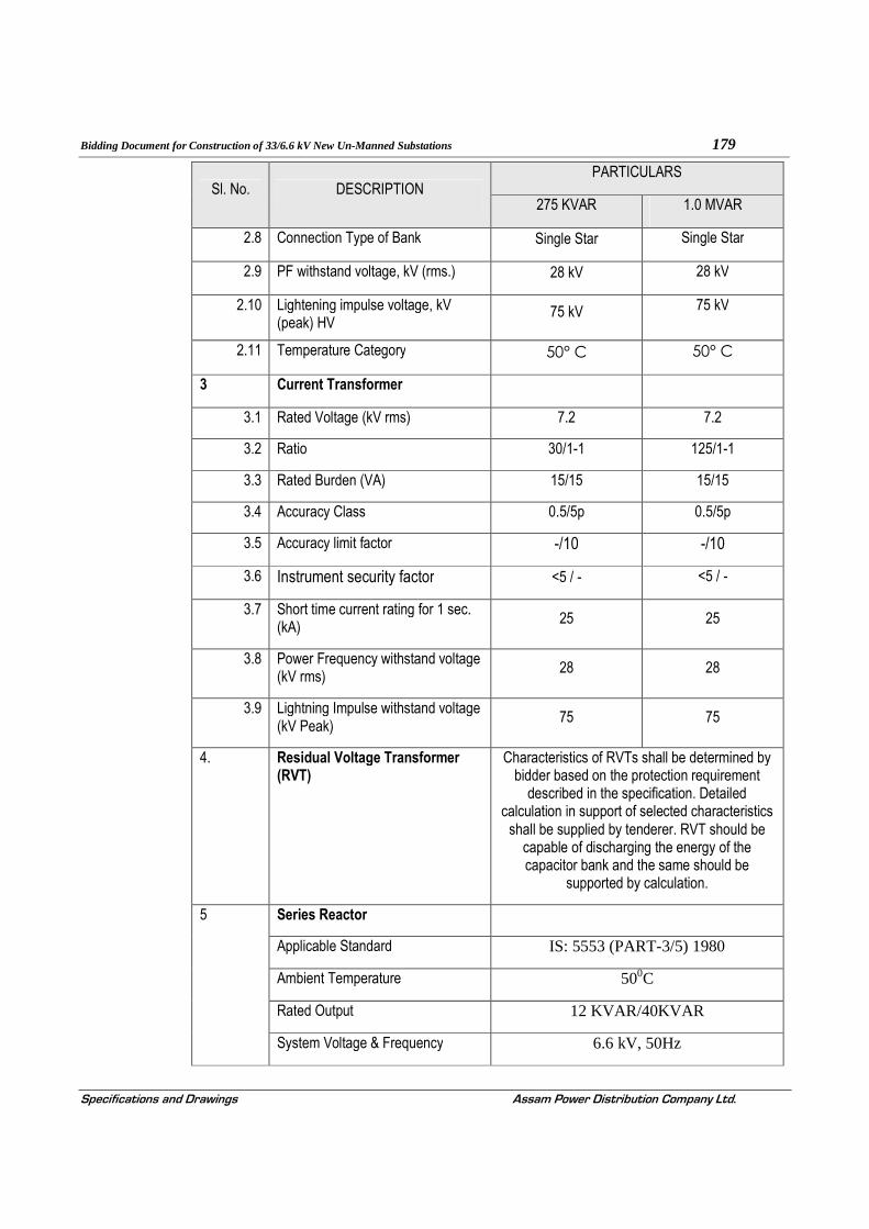
Bidding Document for Construction of 33/6.6 kV New Un-Manned Substations 179
Specifications and Drawings Assam Power Distribution Company Ltd.
Sl. No. DESCRIPTION PARTICULARS
275 KVAR 1.0 MVAR
2.8 Connection Type of Bank Single Star Single Star
2.9 PF withstand voltage, kV (rms.) 28 kV 28 kV
2.10 Lightening impulse voltage, kV (peak) HV
75 kV 75 kV
2.11 Temperature Category 50° C 50° C
3 Current Transformer
3.1 Rated Voltage (kV rms) 7.2 7.2
3.2 Ratio 30/1-1 125/1-1
3.3 Rated Burden (VA) 15/15 15/15
3.4 Accuracy Class 0.5/5p 0.5/5p
3.5 Accuracy limit factor -/10 -/10
3.6 Instrument security factor <5 / - <5 / -
3.7 Short time current rating for 1 sec. (kA) 25 25
3.8 Power Frequency withstand voltage (kV rms)
28 28
3.9 Lightning Impulse withstand voltage (kV Peak)
75 75
4. Residual Voltage Transformer (RVT)
Characteristics of RVTs shall be determined by bidder based on the protection requirement
described in the specification. Detailed calculation in support of selected characteristics
shall be supplied by tenderer. RVT should be capable of discharging the energy of the capacitor bank and the same should be
supported by calculation.
5 Series Reactor
Applicable Standard IS: 5553 (PART-3/5) 1980
Ambient Temperature 500C
Rated Output 12 KVAR/40KVAR
System Voltage & Frequency 6.6 kV, 50Hz

Bidding Document for Construction of 33/6.6 kV New Un-Manned Substations 180
Specifications and Drawings Assam Power Distribution Company Ltd.
Sl. No. DESCRIPTION PARTICULARS
275 KVAR 1.0 MVAR
Rated Continuous current Minimum 130% of Rated Current
Rated short time current Minimum 16 times rated current for 2 sec
Type of shielding Non magnetically shielded
Type of core & cooling Air Core, ONAN
Type of incoming and outgoing terminal
11kV Porcelain bushing
Winding material Copper
Temp. rise in winding 550C
Temp rise in oil 500C
PF withstand voltage 28kV RMS
Impulse withstand voltage 75kV PEAK
Position w.r.t capacitor bank Line end
Paint Shade RAL 7032

Bidding Document for Construction of 33/6.6 kV New Un-Manned Substations 181
Specifications and Drawings Assam Power Distribution Company Ltd.
SECTION - 14
TECHNICAL SPECIFICATION OF GALVANISED STEEL TUBULAR POLE
14.1.0. SCOPE
14.1.1. This specification covers the general requirements towards design, manufacture, testing at manufacturers works, supply and delivery for tubular galvanized steel poles of circular cross section ( swaged type ) for overhead lines.
14.2.0. STANDARD :
14.2.1. The tubular steel poles shall conform to the latest edition of Indian Standard specification
• IS: 2713 ( Part – I, III ) : 1980 Specification for Steel Tubular poles • IS 2626 • The Steel Tubular Poles conforming to other internationally accepted, which ensure equal or higher
quality than the standards, mentioned above also be acceptable. In case the bidder who wish to offer material
conforming to the other standards, salient points of difference between adopted and specific standards with
authentic English Translation shall be furnished.
14.3.0. Topography and Climatic Condition :
14.3.1. The materials offered, shall be suitable for operation in tropical climate and will be subjected to the sun and inclement weather and shall be able to withstand wide range of temperature variation. For the purpose of design, average atmospheric temperature may be considered to be 50 °C with humidity nearing saturation.
14.4.0. Materials :
14.4.1. The materials used in construction of tubular steel poles shall be of the tested quality of steels of minimum tensile strength 540 MPa ( : 55 Kgf/mm2 ).
14.4.2. The materials, when analysed in accordance with IS : 228 ( Part-III : 1972 ) and IS : 228 ( Part-IX) shall not show sulpher and phosphorous contents of more than 0.060 percent each.
14.4.3. The pole shall be hot dip galvanized both out and inside and the Zink coating shall be 630 gm/m2 as per relevant standard.
14.4.4. The manufacturer galvanization plant shall be such that the length of the hot dip shall not less than the total length of the pole. The manufacturer has to submit authenticated evidence of galvanization plant and process or else offer will be rejected.
14.5.0. Types, Size and construction :
14.5.1. Tubular Steel Poles shall be swaged type.
14.5.2. Swaged poles shall be made of seamless or welded tubes of suitable lengths swaged and jointed together. No circumferential joints shall be permitted in the individual tube lengths of the poles. If welded tubes are used they shall have one longitudinal weld seam only : and the longitudinal welds shall be staggered at each swaged joint.

Bidding Document for Construction of 33/6.6 kV New Un-Manned Substations 182
Specifications and Drawings Assam Power Distribution Company Ltd.
14.5.3. Swaging may be done by any mechanical process. The upper edge of each joint shall be chamfered if at an angle of about 450 The upper edge need not be chamfered if a circumferential weld is to be deposited in accordance with clause No. 532 of IS: 2713 ( Part-I) :1980.
14.5.4. The length of joints on swaged poles shall be in accordance with clause No. 5.4 of IS: 2713(Par-I): 1980.
14.5.5. Poles shall be well-finished, clean and free from harmful surface defects. Ends of the poles shall be cut square. Poles shall be straight, smooth and cylindrical. The weld joints, if any, shall be of good quality, free from scale, surface defects, cracks, etc.
14.5.6. Tolerances for outside diameter, thickness, length, weight and straightness shall be in accordance with IS: 2713 (Part-I) : 1980.
14.6.0. Earthing Arrangements :
14.6.1. For earthing arrangement a through hole of 14mm diameter shall be provided in each pole at a height of 300mm above the planting depth.
14.7.0. PRINCIPAL PARAMETERS
SN ITEM DESCRIPTION PARAMETERS
1. Type of Pole SP-76
2. Overall Length 14.5 M
3. Planting Depth 2.0 M
4. Load Applied from top at a distance of
0.50 M
5. Height above ground 12.5 M
6. Length of sections
a. a Bottom 6.5 M
b. Middle 4.0 M
c. Top 4.0 M
7. Outside Diameter & thickness of section
a Bottom, mm 273 x10.90
b Middle ,mm 219 x 9.30
c Top,mm 168.3 x 7.2
8. Base Plate A Mild Steel base plate of size 400 mm x 400 mm x 12 mm shall be welded at the bottom of the pole.
9. Galvanization The inner side & outer side and thickness shall be not less than 90 micron.

Bidding Document for Construction of 33/6.6 kV New Un-Manned Substations 183
Specifications and Drawings Assam Power Distribution Company Ltd.
14.8.0. Tests and Test Certificates :
14.8.1. The following tests shall be conducted on finished poles :
a. Tensile test and chemical analysis for sulpher and phosphorous , b. Defoliation test, c. Permanent set test, and d. Drop test. e. Galvanization test
14.8.2. In addition to above verification of dimensions as per IS : 2713 (Part-III) : 1980 shall be carried out during acceptance of lots.
14.8.3. Number of poles selected for conducting different tests shall be in accordance to clause No.10.1.1 and No. 10.1.12: of IS: 2713 (Part-I) 1980.
14.8.4. Tests shall be carried out before supply of each consignment at the manufacturers woks and test certificates should be submitted to the purchaser for approval prior to delivery.
14.8.5. Re-tests, if any, shall be made in accordance with IS: 2713 (Part-I) 1980.
14.8.6. Purchaser reserves the right to inspect during manufacturing and depute his representative to inspect/test at the works.
14.8.7. If any extra cost is required for carrying out the above specified tests, the same shall be borne by the tenderer.
14.9.0. Marking :
14.9.1. The poles shall be marked with designation, manufacturer’s identification, year of manufacture and name of the purchaser: APDCL
14.9.2. The poles may also be marked with the ISI certification mark if applicable.
14.10.0. Performance :-
14.10.1. The bidder shall furnish a list of the major supplies effected during the last 3 (three) years indicating the volume of supply and actual delivery dates alongwith the bids.
14.10.2. Bids may not be considered if the past manufacturing experience is found to be less that 3 (three) years.
14.11.0. Deviation :-
14.11.1. Any deviation in technical specification shall be clearly indicated with sufficient reasons thereof. Purchaser shall however reserve the right to accept and/or reject the same without assigning any reasons what-so-ever.
14.12.0. Guaranteed technical particulars :
14.12.1. The tenderer shall furnish all necessary guaranteed technical particulars in the prescribed proforma in the last Section of the document.

Bidding Document for Construction of 33/6.6 kV New Un-Manned Substations 184
Specifications and Drawings Assam Power Distribution Company Ltd.
SECTION - 15
TECHNICAL SPECIFICATION FOR GALVANIZED CHANNEL CROSS ARMS
15.1.0. SCOPE :
This specification covers the design, manufacture, testing at manufacturer's works, transport to site, insurance, storage, erection and commissioning of Galvanized Cross Arm and channel used for 33/6.6 KV, Pole mounted substation complete with all accessories as specified.
15.2.0. Standards
15.2.1. The Galvanized Cross Arm and channel supplied under this specification shall conform the latest issue of the relevant Indian Standards IS – 226:1975, Regulations etc. except where specified otherwise.
15.2.2. The rolling and cutting tolerance for steel product conforming to IS: 266 shall be those specified in the IS: 1852-1973 with latest revision.
15.2.3. Galvanization conforming to latest version of 1S:2629
15.2.4. In the event of conforming to any standards other than the Indian Standards, the salient features of comparison shall be clearly set out separately
15.3.0. GENERAL REQUIREMENT :
15.3.1. The cross arm shall be fabricated grade of mild steel of channel section as per requirement.
15.3.2. All steel members and other parts of fabricated material as delivered shall be free of warps, local deformation, unauthorized splices, or unauthorized bends.
15.3.3. Bending of flat strap shall be carried out cold. Straightening shall be carried out by pressure and not by hammering. Straightness is of particular importance if the alignment of bolt holes along a member is referred to its edges.
15.3.4. Holes and other provisions for field assembly shall be properly marked and cross referenced. Where required, either by notations on the drawing or by the necessity of proper identification and fittings for field assembly, the connection shall be match marked.
15.3.5. A tolerance of not more than 1mm shall be permitted in the distance between the center lines of bolt holes. The holes may be either drilled or punched and, unless otherwise stated, shall be not more than 2mm greater in diameter than the bolts.
15.3.6. When assembling the components force may be used to bring the bolt holes together (provided neither members nor holes are thereby distorted) but all force must be removed before the bolt is inserted. Otherwise strain shall be deemed to be present and the structure may be rejected even though it may be, in all other respects, in conformity with the specification.
15.3.7. The back of the inner angle irons of lap joints shall be chamfered and the ends of the members cut where necessary and such other measures taken as will ensure that all members can be bolted together without strain or distortion. In particular, steps shall be taken to relieve stress in cold worked steel so as to prevent the onset of embitterment during galvanizing.

Bidding Document for Construction of 33/6.6 kV New Un-Manned Substations 185
Specifications and Drawings Assam Power Distribution Company Ltd.
15.3.8. Similar parts shall be interchangeable.
15.3.9. Shapes and plates shall be fabricated and assembled in the shop to the greatest extent practicable. Shearing flame cutting and chipping shall be done carefully, neatly and accurately. Holes shall be cut, drilled or punched at right angles to the surface and shall not be made or enlarged by burning. Holes shall be clean-cut without torn or ragged edges, and burrs resulting from drilling or reaming operations shall be removed with the proper tool.
15.3.10. Shapes and plates shall be fabricated to the tolerance that will permit field erection within tolerance, except as otherwise specified. All fabrication shall be carried out in a neat and workmanlike manner so as to facilitate cleaning, painting, galvanizing and inspection and to avoid areas in which water and other matter can lodge.
15.3.11. Contact surfaces at all connections shall be free of loose scale, dirt, burrs, oil and other foreign materials that might prevent solid seating of the parts.
15.3.12. Welded joints not permissible.
15.3.13. The rolling and cutting tolerance for steel product conforming to IS: 266 shall be those specified in the IS: 1852-1973 with latest revision.
all dimensions are subject to the following tolerances:
a) dimensions up to and including 50mm:+1mm: and
b) dimensions greater than 50mm: +2%
15.3.14. The channel cross arm shall be properly brushed to make it free from rust.
15.4.0. For galvanized channel :
15.4.1. All ferrous parts including all sizes of nuts, bolts, plain and spring washers, support channels, structures, shall; be hot dip galvanized conforming to latest version of 1S:2629 or any other equivalent authoritative standard. The zinc coating shall be smooth, continuous and uniform. It shall be free from acid spot and shall not scale, blister or be removable by handling or packing. There shall be no impurities in the zinc or additives to the galvanic bath which could have a detrimental effect on the durability of the zinc coating. Before picking, all welding, drilling, cutting, grinding and other finishing operations must be completed and all grease, paints, varnish, oil, welding slag and other foreign matter completely removed. All protuberances, which would affect the life of galvanizing shall also be removed.
15.4.2. The weight of zinc deposited shall be in accordance with that stated in Standard IS 2629 and shall not less than 0.61kg/m² with a minimum thickness of 86 microns for items of thickness more than 5mm, 0.46kg/m² (64 microns) for items of thickness between 2mm and 5mm and 0.33kg/m² (47 microns) for items less than 2mm thick.
15.4.3. The raw materials and fabrication thereof in respect of cross arm shall be furnished along with dimension.
15.4.4. The hole for fixing of insulator and pole clamp shall be provided as per requirement.
15.4.5. One copy of the drawing of cross arm for each size shall be furnished along with the technical bid.

Bidding Document for Construction of 33/6.6 kV New Un-Manned Substations 186
Specifications and Drawings Assam Power Distribution Company Ltd.
15.5.0. Data Sheet
REQUIRED TECHNICAL SPECIFICATION FOR GI CHANNEL CROSS ARM
[100x50x6 x 5000 mm ]
Sl No. Description Particular
1 Type of cross arm G.I Channel cross arm
2 Size 100 x 50x 6 x 5000
3 Material Mild Steel channel
4 Length 5000 mm
5 Breath 100 mm
6 Width 50 mm
7 Thickness 6 mm
8 Hole for fixing of insulator 26 mm
9 Galvanization The cross arm shall be properly brushed to make it free from rust and hot dip galvanized confirming to IS: 2629.
10 Standard applicable IS: 266; IS: 1852-1973:

Bidding Document for Construction of 33/6.6 kV New Un-Manned Substations 187
Specifications and Drawings Assam Power Distribution Company Ltd.
SECTION - 16
TECHNICAL SPECIFICATION FOR DISTRIBUTION TRANSFORMER
16.1.0. SCOPE
16.1.1. This section of the specifications is intended to cover requirements for design, engineering, manufacture, testing/inspection at manufacturer’ works before despatch, forwarding, packing, transporting and delivery at site of outdoor type naturally air-cooled, 33kV/433-250V Distribution Transformers of capacities 1600 & 250 KVA complete with all accessories/fittings and spare parts. The bidder shall quote the price of transformer complete with first filling of oil.
16.2.0. BIDDING
16.2.1. Each Technical Proposal must be accompanied by each of the following information/ documents with sufficient details along with other documents and information mentioned elsewhere to enable the purchaser to make an appraisal of the quality and suitability of the material and equipment offered.
(a) Type test certificates of transformer of identical design from a nationally recognised laboratory, preferably at CPRI/ERDA laboratory. The Type test certificates should not be more than 3 (three) years old. The type rest certificates should also be accompanied by the drawings of equipment tested so that the test certificates can be directly linked to the equipment offered. In this regard following points shall also be noted:
Equipment which have not been type tested as above shall not be accepted. A promise or agreement by a bidder to have the equipment tested after award of a contract is not acceptable.
(b) Type Test reports to be acceptable must relate directly to the equipment offered. Type Test reports for a higher class/rating of equipment are acceptable with a commitment from bidder that the type test will be performed free of charge on the particular equipment after the award of contract.
(c) Guaranteed and Other Particulars in the formats given in Section-17 at the end of the Section of this document. The bid should also be accompanied by manufacturer’s literatures and brochures.
16.2.2. Failure to meet the requirement of this Clause 4.2.0 shall render a Bid non-responsive.
16.3.0. STANDARDS
16.3.1. The Transformer and associated accessories shall conform to the latest issues of the standards as given below, except to the extent explicitly modified in this specification.
(1) CBIP manual on Transformers. Publication no 275
(2) Power Transformers IS:2026, IEC 76
(3) Insulating oils for transformers and switchgears IS:335
(4) Bushings for alternating voltages above 1000 V IS:2099
(5) Creepage distance (mm) IS: 3347

Bidding Document for Construction of 33/6.6 kV New Un-Manned Substations 188
Specifications and Drawings Assam Power Distribution Company Ltd.
(6) Outdoor Bushings IS:3347, DIN 42531 to 33
(7) Specification for low voltage bushings IS:7421
(8) Dimensions for clamping arrangements for bushings IS:4257
(9) Specification for Al Wire rods IS: 5434, ASTM B-233
(10) Specification for Insulating Kraft Paper IS:9335, IEC 554
(11) Specification for Insulating Press Board IS:1576, IEC 641
(12) Code of practice for installation and maintenance IS:10028
of transformers
(13) Guide for loading of oil immersed transformers IS:6600
(14) Paper covered Aluminium conductor IS:6162
(15) Rectangular Electrical conductor for electrical machine IS:6160
(16) Electrical Power connector IS: 5561
(17) Colours for ready mix paints. IS: 5
(18) Ready mixed paint, brushing zinc chromate, priming IS 104
(19) Specification for Copper wire rod IS 12444, ASTM B-49
(20) Testing for steel sheets and strips and magnetic circuits IS-649
1.1 In case equipment conforms to other international standard which ensure equivalent or better performance than that specified under Clause 16.3.1, then relevant Standards shall be forwarded with the bid.
16.4.0. GENERAL SERVICE CONDITION
16.4.1. The climatic conditions at site under which the equipment shall operate satisfactorily are as follows:-
(a) Maximum temperature of air in shade 50º C
(b) Minimum temperature of air in shade: - 2º C (c) Maximum average daily ambient air temperature 400C (d) Maximum yearly weighted average ambient temperature 320C (e) Maximum Humidity: 100% (f) Average of rainy days per annum: 150 (g) Average number of days of thunderstorm per annum: 45
(h) Average number of days of dust storm per annum: 25
(i)Average annual rainfall: 2280 mm
(j) Number of months of tropical monsoon per annum: 5 (May to Sept)
(k) Maximum wind pressure: 150Kg/m2
(l) Altitude (above mean sea level): 50 to 200 m

Bidding Document for Construction of 33/6.6 kV New Un-Manned Substations 189
Specifications and Drawings Assam Power Distribution Company Ltd.
16.5.0. GENERAL TECHNICAL SPECIFICATIONS:
16.5.1. The Distribution transformer shall be 3-phase; oil immersed and shall have core type construction, and should be suitable for outdoor service in hot and humid tropical climate.
16.5.2. The transformers and all its accessories shall be designed to withstand without injury, the thermal and mechanical effects of any external short circuit to earth and of short circuits at the terminals of any winding of values and duration specified in IS-2026.
16.5.3. The transformer shall be capable of being loaded in accordance with IS: 6600. There shall be no limitation imposed by bushings etc.
16.5.4. The transformer shall be capable of being operated without danger on any tapping at the rated kVA with voltage variation of plus or minus 10% corresponding to the voltage of that tapping with normal temperature rise. The design adopted to achieve this shall be indicated in detail in the offer.
16.5.5. The transformer shall be suitable for continuous operation with frequency variation of ±5% from normal 50Hz.Combined voltage and frequency variation should not exceed the rated V/f ratio by 10%.
16.5.6. Transformer shall be capable of withstanding thermal and mechanical stress caused by symmetrical or asymmetrical faults on any winding. The calculation for the same to be submitted along with the offer
16.5.7. Transformer shall accept, without injurious heating, combined voltage and frequency fluctuation, which produces the following over fluxing conditions:
16.5.8. i) 125% for 1 minute or 140% for 5 seconds
16.5.9. ii) Over fluxing withstand characteristics up to 140% shall be submitted along with the bid.
16.5.10. The thermal ability to withstand short circuit shall be demonstrated by calculation.
16.5.11. The maximum flux density in any part of the core and yokes, at normal voltage and frequency of transformer shall be such that the flux density under over voltage condition as per Clause 16.5.5 above shall not exceed 1.9 Tesla. The detail calculation is to be shown as per Annexure-I.
16.5.12. Maximum Flux Density in any part of the core and yoke at rated KVA, Maximum System voltage [36 KV] and minimum system frequency [48.5 HZ] shall not exceed 1.6 Tesla.
16.5.13. The maximum magnetising current at 110% rated voltage shall not be more than 125% of that at 100% rated voltage. Accordingly, the operating flux density for design should be carefully chosen within the stipulated value to achieve the above requirement. The Bidder shall quote the practically achievable no load current at different percentages of rated voltage as per Guaranteed Technical Particulars which will be verified during no load test.
16.5.14. The maximum current density in any winding shall not exceed 2.50A/sq.mm.
16.5.15. The sources of prime materials, place of manufacture, testing and inspection should be shown as per the proforma enclosed in Annexure – VI.
16.6.0. SUPPRESSION OF HARMONICS
The transformers shall be designed with particular attention to the suppression of harmonic voltage, especially the third and fifth, so as to eliminate wave form distortion.
16.7.0. CENTRE OF GRAVITY
Bidding Document for Construction of 33/6.6 kV New Un-Manned Substations 190
Specifications and Drawings Assam Power Distribution Company Ltd.
The center of gravity of the assembled transformers shall be low and as near to the vertical center line as possible. The transformer shall be stable with or without oil. If the center of gravity is eccentric relating to track either with or without oil, its location shall be shown on the outline drawing.
16.8.0. GENERAL CONSTRUCTIONAL FEATURES
16.8.1. GENERAL
16.8.1.1. All material used shall be of best quality and of the class most suitable for working under the conditions specified and shall withstand the variations of temperature and atmospheric conditions without distortion or deterioration or the setting up of undue stresses in any part and also without effecting the strength and suitability of the various parts for the work which they have to perform.
16.8.1.2. Similar parts, particularly removable ones, shall be interchangeable.
16.8.1.3. Pipes, screws, studs, nuts and bolts used for external connections shall be as per the relevant standards. Steel bolts and nuts exposed to atmosphere shall be galvanized.
16.8.1.4. Nuts, bolts and pins used inside the transformers and tap changer shall be provided with lock washers or locknuts.
16.8.1.5. Exposed parts shall not have pockets where water can collect.
16.8.1.6. Internal design of transformer shall ensure that air/gas is not trapped in any location.
16.8.1.7. Material in contact with oil shall be such as not to contribute to the formation of acid in oil. Surface in contact with oil shall not be galvanized or cadmium plated.
16.8.1.8. Labels, indelibly marked, shall be provided for all identifiable accessories. All label plates shall be of non corrodible material.
16.8.1.9. All internal connections and fastenings shall be capable of operating under overloads and over-excitation, allowed as per specified standards without injury.
16.8.1.10. Transformer and accessories shall be designed to facilitate proper operation, inspection, maintenance and repairs.
16.8.1.11. No patching, plugging, shimming or other such means of overcoming defects; discrepancies or errors will be accepted.
16.9.0. SURFACE PREPERATION & PAINTING
16.9.1. GENERAL
Refer to Clause 4.13.1,4.13.2, of Section – 4 of this document. 16.9.1.1.
16.10.0. CORE (MAGNETIC CIRCUIT) AND CONSTRUCTIONAL FEATURES OF CORE
16.10.1. Refer to Clause No. 4.13.4, 4.13.5, 4.13.5, 4.13.6, 4.13.7,of Section-4, of this bidding document.
16.11.0. WINDING
16.11.1. GENERAL
i) The current density of copper in any part of the windings shall not exceed 2.50 Amps/Sq. mm.
ii) All windings shall be made of electrolytic high conductivity copper for transformer of capacity 250 KVA and above and shaped and braced to provide for expansion and contraction due to

Bidding Document for Construction of 33/6.6 kV New Un-Manned Substations 191
Specifications and Drawings Assam Power Distribution Company Ltd.
temperature changes. Winding shall be fully insulated as defined in IS: 2026. All neutral points shall be insulated for the voltage specified in IS: 2026. The winding shall be so designed that all coil assemblies of identical voltage, rating shall be interchangeable.
iii) HV winding shall be of continuous disc type.
iv) LV coil shall be spiral type winding construction.
v) Coil shall be clamped by 8 (eight) numbers of stud and the size should not be less than 20 mm.
vi) LV winding shall be such that neutral formation will be at top.
vii) Conductor covering for HV winding shall be TPC with minimum 0.35 mm thickness and for LV conductor TPC with minimum 0.50 mm thickness.
viii) Interlayer insulation shall be Nomex/Epoxy dotted Kraft Paper.
ix) Distribution Transformers shall be designed to withstand the impulse and power frequency test voltages as per IS: 2026.
x) Magnitude of impulse surges transferred from HV to LV windings by induction and capacitance coupling shall be limited to B.I.L. of LV winding.
xi) The completed core and coil assembly shall be dried in vacuum at not more than 0.5mm of mercury absolute pressure and shall be immediately impregnated with oil after the drying process to ensure the elimination of air and moisture within the insulation. Vacuum may be applied in either vacuum oven or in the transformer tank
xii) Winding shall be subjected to a shrinking and seasoning process, so that no further shrinkage occurs during service. Adjustable devices shall be provided for taking up possible shrinkage in service.
xiii) Winding shall not contain sharp bends which might damage the insulation or produce high dielectric stresses. No strip conductor wound on edge shall have width exceeding six times the thickness.
xiv) Varnish application on coil windings may be given only for mechanical protection and not for improvement in dielectric properties. In no case varnish or other adhesive be used which will seal the coil and prevent evacuation of air and moisture and impregnation by oil.
xv) The winding shall be designed to reduce to a minimum, the out-of balance forces in the transformers at all voltage ratios.
xvi) The insulation of transformer windings and connection shall be free from insulating composition liable to soften, ooze out ,shrink or collapse during service and be non catalytic and chemically inactive in transformer oil.
xvii) The coil clamping arrangement and the finished dimensions of any oil ducts shall be such as will not impede the free circulation of oil through the ducts.
xviii) Terminals of all windings shall be brought out of the tank through bushings for external connections

Bidding Document for Construction of 33/6.6 kV New Un-Manned Substations 192
Specifications and Drawings Assam Power Distribution Company Ltd.
xix) The winding shall be so designed that all coil assemblies of identical voltage ratings shall be interchangeable and field repairs to the winding can be made readily without special equipment. The coils shall have high dielectric strength
xx) All leads from windings to terminals shall be rigidly supported to prevent injury from vibration. Guide tubes may be used where possible.
16.11.2. BRACING OF WINDINGS
16.11.2.1. The windings and connections of all transformers shall be braced to withstand shocks, which may occur during transport or due to switching and other transient conditions during service.
i) Coil clamping rings shall be of suitable insulating material.
ii) Permanent current carrying joints in the windings and leads shall be welded or brazed. Clamping bolts for current carrying parts inside oil shall be made of oil resistant material which shall not be affected by acidity in the oil steel bolts, if used, shall be suitably treated.
iii) Adequate barriers shall be provided between coils and core and between high and low voltage coil. End turns shall have additional protection against abnormal line disturbances.
iv) Coil should be clamped by 8 (eight) numbers of 20 mm dia tie rods between top and bottom yoke support channels.
16.11.3. BOLTS AND NUTS
16.11.3.1. Steel bolts and nuts exposed to atmosphere with suitable finishes like cadmium plated or zinc plated passivated will be used for diameter above 6 mm.
16.11.3.2. Brass bolts and nuts of less than 6 mm shall not be used for electrical connections. Where smaller size is required, stainless steel or phosphor bronze may be used. Sizes and threads will be as per Indian Standard, wherever, available, otherwise equivalent British Standard will be followed.
16.11.3.3. All nuts and bolts and pins shall be locked in position with the exception of those external to the transformer. The bolts shall be fitted in such a manner that in the event of the nut working loose and falling off, the bolts will remain in position.
16.11.3.4. All bolts, nuts and washers in contact with non-ferrous parts which carry current and are exposed to atmosphere shall be of phosphor bronze, where transfer of current is through bolts.
16.11.3.5. If bolts and nuts are placed that are in accessible by means of ordinary spanners, suitable special spanners shall be provided by the supplier.
16.12.0. INSULATION MATERIAL:
16.12.1. Electrical grade insulation epoxy dotted Kraft Paper/Nomex and pressboard of standard make or any other superior material subject to approval of the purchaser shall be used.
16.12.2. All spacers, axial wedges / runners used in windings shall be made of pre-compressed Pressboard solid, conforming to type B 3.1 of IEC 641 – 3 – 2 . For cross-over coil winding of HV all spacers shall be properly sheared and dovetail punched to ensure proper locking. All axial wedges / runners shall be properly milled to dovetail shape so that they pass through the designed spacers freely. Insulation

Bidding Document for Construction of 33/6.6 kV New Un-Manned Substations 193
Specifications and Drawings Assam Power Distribution Company Ltd.
shearing, cutting, milling and punching operations shall be carried out in such a way, that there should not be any burr and dimensional variations.
16.12.3. Insulating Oil
16.12.3.1. Refer to Clause No. 4.13.10, of Section-4 of this bidding document.
16.13.0. ACCESSORIES & FITTINGS
16.13.1. BUSHINGS:
16.13.1.1. The bushing shall conform to the relevant standards specified and shall be of outdoor type. The bushing rods and nuts shall be made of brass material 12 mm diameter for HT bushings. The tests as per latest IS:2099 and IS:7421 shall be conducted on the transformer bushings.
16.13.1.2. The HV side shall be protected by HRC fuse and the fuse shall be kept prior to bushings. The termination of both the LV and HV bushing shall be through XLPE cable of appropriate ratings.
16.13.1.3. Both HV and LV side bushings shall be mounted horizontally and shall be covered steel sheet of minimum 3.15 mm. The protection class of cover shall be IP55 grade.
16.13.1.4. For protection of LV side, appropriate ACB/MCCB shall be mounted inside the LV bushings outer cover and necessary arrangement shall be made for terminations of LV side outgoing cables.
16.13.1.5. The LV side bushing should be of epoxy type conforming to relevant standards.
16.13.1.6. For 33 KV, 36 kV class bushing and for 0.433 kV, 1.1 kV class bushing shall be used.
16.13.1.7. Dimensions of the bushings of the voltage class shall conform to the Standards specified and dimension of clamping arrangement shall be as per IS:4257.
16.13.1.8. Minimum external phase to phase and phase to earth clearances of bushing terminals shall be as per relevant standards
16.13.1.9. Brazing of all inter connections, jumpers from winding to bushing shall have cross section larger than the winding conductor. All the Brazes shall be qualified as per ASME, section-IX.
16.13.2. TERMINAL CONNECTORS
16.13.2.1. HV side terminal arrangement shall be connected by ACSR WOLF conductor. Connector shall be of universal type.
16.13.2.2. For LV side of 1600 MVA, terminal arrangement shall be designed to accommodate 4 nos. 1-coe 1000 mm2 XLPE cable in one phase and total gland shall be 21 nos.
16.13.3. Earthing Terminal
Two earthing pads (each complete with two nos. (2) tapped holes, M 8 bolts, plain and spring 16.13.3.1.washers) suitable for connection to 40x6 mm galvanised steel flat shall be provided each at position close to the two (2) diagonally bottom corners of the tank.
16.14.0. PROTECTION & MEASURING DEVICES
16.14.1. Conservator Tank
16.14.1.1. The conservator tank shall have adequate capacity between highest and lowest visible levels to meet the requirement of the expansion of the total cold oil volume in the transformer from minimum ambient temperature to 90°C. The total volume of conservator shall be 10% of total oil in the transformer.

Bidding Document for Construction of 33/6.6 kV New Un-Manned Substations 194
Specifications and Drawings Assam Power Distribution Company Ltd.
16.14.1.2. The conservator feed pipe shall be extended 25 mm upwards from the conservator bed so that a sump is created and the design of feed pipe to transformer tank should be such that the oil from conservator does not fall directly to the core & coil assembly.
16.14.1.3. The conservator should have one oil filling hole of 32 mm size with gasketed cover. One air release plug of 15mm size will be required.
16.14.1.4. The conservator tank shall be bolted into position so that it can be removed for cleaning purposes.
16.14.1.5. The conservator tank shall be fitted with prismatic oil level gauge with minimum and maximum marking.
16.14.1.6. The conservator tank shall be provided in a position not to obstruct the electrical connections to the transformers.
16.14.1.7. Conservator tank shall be fitted with dial type MOLG for rating 1.6MVA.
16.14.2. Pressure Relief Device
Pressure relief device shall be provided at suitable locations which shall be of sufficient size for rapid 16.14.2.1.release of any pressure that may be generated in the tank and which may result in damage to the equipment. The device shall operate at the static pressure of less than the hydraulic test pressure of transformer tank. It shall be mounted directly on the tank.
16.14.3. Oil Preservation Equipment
16.14.3.1. Conservator shall be fitted with Air Cell for rating 1.6 MVA with two numbers 8mm air release valve.
16.14.3.2. Air Cell healthy alarm is required, as such device to detect failure of air cell is to be fitted.
16.14.4. Oil Sealing breather
The conservator shall be fitted with a dehydrating filter breather. It shall be so designed that16.14.5.
i) Passage of air is through a dust filter & Silica gel
ii) Silica gel is isolated from atmosphere by an oil seal.
iii) Moisture absorption indicated by a change in colour of the crystals can be easily observed from a distance.
iv) Breather is mounted not more than 1200 mm above rail top level.
v) The breather should have at least 3000g of silica gel per KL of oil.
16.14.6. BUCHHOLZ ELAY
16.14.6.1. Buchholz relay with alarm and trip contact shall be provided for transformer rating 1.6 MVA.
16.15.0. RADIATORS & VALVES
16.15.1. Radiators shall be of press steel having thickness of 1.2 mm Cold Rolled Continuously Annealed (CRCA) sheet. and design should be such that all painted surface can be thoroughly cleaned by hand
16.15.2. VALVES
16.15.2.1. One no. 50 NB valve for oil filtration and 32NB valve for 250 KVA transformer..
16.15.2.2. One no 50 NB bottom drain valve and 32NB valve for 250 KVA transformer.

Bidding Document for Construction of 33/6.6 kV New Un-Manned Substations 195
Specifications and Drawings Assam Power Distribution Company Ltd.
16.15.2.3. Radiators shall be connected through appropriate size of butter fly valve.
16.15.2.4. 8 mm valves for top and bottom oil sampling to be fitted.
16.15.2.5. 15 mm air release plug at the top cover.
16.15.2.6. 15 NB bottom valve for sludge removal.
16.15.2.7. Valves shall be of Gun metal.
16.16.0. FITTINGS AND ACCESORIES
16.16.1. The following fittings shall be provided on each transformer
a) Conservator fitted with oil filling hole and cap.
b) Air cell for transformer rating 1.6 MVA.
c) MOLG for conservator
d) Oil and Winding dial type temperature meter with alarm and trip contact for transformer rating 1.6 MVA.
e) Buchholz relay for rating 1.6 MVA
f) Prismatic type oil gauge
g) Silica gel breather with oil seal.
h) Pressure relief device for main tank.
i) Pocket on tank cover (placed at mid position) for thermometers.
j) Compensation CT for winding temperature.
k) Clamps for HV side LA with earthing strip.
l) Oil level indicator for transformer tank.
m) Valves :-as referred to Clause No. 16.15.2
n) Eearthing terminals with lugs- 2 nos.
o) Rating and diagram plate, non-detachable.
p) Lifting lugs for main tank and top cover.
q) Inspection cover.
r) Terminal connectors on the HV/LV bushing
s) Bi-directional flanged rollers with locking and bolting device.
t) Base channel
u) IP 55 protected 3.15 mm sheet steel Marshalling box with gland plate, Paint shall be polyurethane. (for 1.6 MVA)
v) Foundation bolts for wheel locking devices of Transformer shall be supplied by the Supplier

Bidding Document for Construction of 33/6.6 kV New Un-Manned Substations 196
Specifications and Drawings Assam Power Distribution Company Ltd.
w) Rating Plate
16.17.0. LOSSES
16.17.1. The bidder shall guarantee individually the no-load loss and load loss without any positive tolerance. The bidder shall also guarantee the total losses at 50% and 100% load condition (at rated voltage and frequency and at 750 C) as per Table-I.
Table - I
Rating (KVA) Max. Losses at 50% loading (Watts)
Max. Losses at 100% loading (Watts)
250 1520 5100
1600 4850 16000
The above losses are maximum allowable and there would not be any “+ve” tolerance. Bids with higher losses than the specified values would be treated as non responsive.
For bid evaluation purpose losses will not be capitalized.
16.18.0. CAPITALISATION OF LOSSES AND LIQUIDATED DAMAGES FOR EXCESSIVE LOSSES:
16.18.1. For the purpose of penalty computation, the test figures of the no-load and the total losses of each transformer will be compared with the corresponding guaranteed figures.
16.18.2. Since IS: 2026 allows certain tolerances on the transformer losses, the bidders are requested to indicate whether the figures given for guaranteed losses in the schedule of guaranteed technical particulars are with or without such tolerances. If tolerances are applicable, the limits for the same should be indicated. In the absence of any information to this effect, the figures for no-load losses and load losses will be increased by 10% as provided in the IS. Any change in the figures assigned for transformer losses will not be permitted after opening of bids and bid evaluation will be carried out on the basis of information made available at the time of bid opening.
16.18.3. Penalties will be applicable if any one or more test loss figures of no-load loss and total losses exceed the corresponding guaranteed figures. The penalties will be calculated as follows: -
(a) For No-load loss, Penalty (in rupees) = Wi (t) – Wi (g) x 2R1.
(b) For load loss, Penalty (in rupees) = WT (t) – Wi (t) - WI (g) x 2R2
Where,
WT (t) = Total loss (test value) in kW.
WT (g) = Total loss (guaranteed value) in kW.
Wi (t) = No-load loss (test value) in kW.
Wi (g) = No-load loss (guaranteed value) in kW.
W1 (g) = Load loss (guaranteed value) in kW.( Copper loss )
R1 = Rs.2,38,494/-

Bidding Document for Construction of 33/6.6 kV New Un-Manned Substations 197
Specifications and Drawings Assam Power Distribution Company Ltd.
R2 = Rs.49, 607/-
16.18.4. The loss figures (both guaranteed & test) for the purpose of calculation shall be at rated frequency and voltage and at principal tap and 75º C.
16.18.5. Calculation of detail losses including flux density and no load current are to be furnished for copper loss, iron loss indicating corresponding copper weight and core weight and considering all parameters and also supported by the drawings showings details of diameter and height of winding and core duly signed by manufacturer’s design personnel. The loss calculation is to be shown as per proforma in Annexure – II.
16.19.0. Temperature rise:
16.19.1. The temperature rise over ambient shall not exceed the limit given below:
Top oil temperature rise measured by thermometer : 450 C
Winding temperature rise measured by resistance method : 500 C
Bids not meeting the above limits of temperature rise will be treated as non-responsive.
16.20.0. TESTS & INSPECTION
16.20.1. Refer to Clause No. 4.13.22 of Section – 4 of this bid document volume-2.
16.21.0. REJECTION
16.21.1. The Employer may reject any transformer if during tests or service any of the following conditions arise:
i) No load loss exceeds the guaranteed value by 20% or more.
ii) Load loss exceeds the guaranteed value by 20% or more.
iii) Impedance value exceeds the guaranteed value by ( -) 10% or more.
iv) The difference in impedance values of any two phases during single phase short circuit impedance test exceeds 2% of the average value guaranteed by the vendor.
v) Oil or winding temperature rise exceeds the specified value.
vi) Transformer fails on impulse test.
vii) Transformer fails on power frequency voltage withstand test.
viii) Transformer is proved to have been manufactured not in accordance with the agreed specifications.
16.22.0. DRAWINGS and CALCULATIONS FOR SUBMISSION WITH THE BID
16.22.1. The Bidder shall furnish with his bid following drawings incorporating the details mentioned hereunder.
a) General outline drawing showing dimensions and overall dimensions, sectional view, core and coil assembly drawing, net weights and shipping weights, quantity of insulating oil, spacing of wheels, location off load tap changers etc.
b) Details of the sectional view of core and winding showing the core frame size, coil dia and length, conductor size, lead support etc.

Bidding Document for Construction of 33/6.6 kV New Un-Manned Substations 198
Specifications and Drawings Assam Power Distribution Company Ltd.
c) Hot spot temperature calculation.
d) Demonstration to withstand thermal ability as per IS:2026
e) Calculation of thermal time constant.
f) Calculation for thermal and mechanical stress caused by symmetrical or asymmetrical faults on any winding.
g) Calculation of detail losses including flux density and no load current are to be furnished for copper loss, iron loss indicating corresponding copper weight and core weight and considering all parameters and also supported by the drawings showings details of diameter and height of winding and core duly signed by manufacturer’s design personnel.
h) GA drawings/details of various types of bushings and connectors.
i) Illustrative & descriptive literature of the Transformer
j) List of customers to whom similar equipments have been supplied.
k) Type test certificates from a recognized institute preferably CPRI of equipment of similar design and rating.
l) Performance report of equipment of similar design and rating which is in satisfactory operation for at least three years. Performance report issuing officer’s rank should be S.E./ DGM and above of the utility.
16.23.0. QUALITY ASSURANCE PLAN:
The bidders shall invariably furnish the following information in respect of quality assurance, failing which, offers are liable to be ignored.
(a)
(i) List of important raw materials (CRGO laminations, wires and strips, transformer oil, insulating paper, press board, bushings and terminal connectors etc.)
(ii) Name of Suppliers/ sub suppliers
(iii) List of standards which are followed during testing of raw materials.
(iv) List of test carried out on raw materials along with test certificate.
(b) List of manufacturing facilities.
(c) Level of automation achieved.
(d) Quality control on stages of manufacturing process along with inspection reports.
(e) List of testing equipments available along with valid calibration certificates.
Quality Assurance Plan (QAP) with hold points for Purchaser’s Inspection as per Annexure – III.
16.24.0. DATA SHEET

Bidding Document for Construction of 33/6.6 kV New Un-Manned Substations 199
Specifications and Drawings Assam Power Distribution Company Ltd.
SL
NO
DESCRIPTION TRANSFORMER CLASS
33/0.433-0.250 KV
1. Continuous KVA Ratings (CMR) 1600 & 250,
2. Number of phases 3
3. Rated voltage kV
i) Primary (HV) ii) Secondary (LV)
33 0.433
4. Highest System Voltage, kV
i) Primary (HV) ii) Secondary (LV)
36 1.1 of Un
5. Rated frequency, Hz. 50±5%
6. Connection of HV, LV HV Delta & LV Star with neutral solidly earthed
7. Method of system earthing Solidly earthed
8. Vector group DYN 11
9. Insulation Level:
i) PF withstand voltage, kV (rms.): HV 70
ii) PF withstand voltage, kV (rms.): LV 3
iii) Lightening impulse voltage, kV (peak) HV
170
9.2 Minimum Insulation resistance at 200C HV- E : > 2000 MW
LV – E : > 1000 MW
10. Percentage Impedance at 75°C and at principal tap
6.25% / 5%
11. Maximum flux density at rated KVA, Maximum System voltage [12 KV/1.1 KV] and minimum system frequency [48.5 HZ],
1.6
12. Method of cooling ONAN
13. Type of tap changer Off Load
14. Number of taps (+)5% to (-)10% in 5 steps of 2.5% for HV variation

Bidding Document for Construction of 33/6.6 kV New Un-Manned Substations 200
Specifications and Drawings Assam Power Distribution Company Ltd.
SL
NO
DESCRIPTION TRANSFORMER CLASS
33/0.433-0.250 KV
15. Core material HIB, 0.23 mm (thickness)
16. Winding Electrolytic copper
17. Clearance of air, mm
a) phase to phase, HV / LV
b) phase to earth, HV / LV
400 / 75
320 / 40
18. No load current at rated voltage and rated frequency
1.5% of FLC (250 KVA)/
1% of FLC for 1.6 MVA
19. No load current at 1.1UN voltage and rated frequency
For 250 KVA 4% of FLC
For 1.6 MVA 3% FLC
20. Maximum current density 2.50 Amp / sq. mm for Copper
21. Temperature Rise, 0C
(i) Winding (measured by resistance.
(ii) Top Oil (measured by thermometer)
45
50
22. Bushings:
1. Rated voltage in kV
1.1 HV bushing 36
1.2 LV bushing 1.1
1.3 Neutral bushing 1.1
2. Rated current in Ampere
2.1 HV bushing As per IS: 3347 Part III (Section 1 & 2)
2.2 LV bushing As per IS: 3347 Part I (Section 1 & 2)
2.3 Neutral bushing As per IS: 3347 Part I (Section 1 & 2)

Bidding Document for Construction of 33/6.6 kV New Un-Manned Substations 201
Specifications and Drawings Assam Power Distribution Company Ltd.
SL
NO
DESCRIPTION TRANSFORMER CLASS
33/0.433-0.250 KV
3. Rated impulse withstand voltage in kV rms.
3.1 HV bushing 195
4. One-minute power frequency withstand test in kV (rms.)
4.1 HV bushing 70
4.2 LV bushing 3
4.3 Neutral bushings 3
5. Minimum Creepage distance in mm
5.1 HV bushing 900
5.2 LV bushing 55
5.3 Neutral 55
23. Auxiliary DC supply voltage 48V
16.25.0. GUARANTEE:
16.25.1. The manufacturers of the transformers shall provide a guarantee of sixty (36) months from the date of receipt at the site of APDCL substation
16.25.2. In case of failure within the guarantee period the APDCL will immediately inform the supplier who shall take back the failed DTR within 15 days from the date of intimation at his own cost and replace/repair the transformer within thirty (30) days of date of intimation with a roll over guarantee.
16.25.3. The outage period i.e. period from the date of failure till unit is repaired/replaced shall not be counted for arriving at the guarantee period.
16.25.4. In the event of supplier’s inability to adhere to the aforesaid provision, suitable penal action will be taken against the supplier which may inter alia include blacklisting of the firm for future business with the APDCL for a certain period.
16.26.0. SCHEDULES:
16.26.1. The bidder shall fill in the following schedule which will be part of the offer. If the schedule are not submitted duly filled in with the offer, the offer shall be liable for rejection.
Schedule – for Guaranteed Technical Particulars

Bidding Document for Construction of 33/6.6 kV New Un-Manned Substations 202
Specifications and Drawings Assam Power Distribution Company Ltd.
Schedule – B :Schedule of Deviations
16.27.0. DEVIATIONS:
16.27.1. The bidders are not allowed to deviate from the principal requirements of the Specifications. However, the bidder is required to submit with his bid in the relevant schedule a detailed list of deviations without any ambiguity. In the absence of a deviation list in the deviation schedule, it is understood that such bid conforms to the bid specifications and no post-bid negotiations shall take place in this regard.
16.27.2. The discrepancies, if any, between the specification and the catalogues and/or literatures submitted as part of the offer by the bidders, shall not be considered and representations in this regard shall not be entertained.
16.27.3. If it is observed that there are deviations in the offer in guaranteed technical particulars other than those specified in the deviation schedules then such deviations shall be treated as deviations.
16.27.4. All the schedules shall be prepared by vendor and are to be enclosed with the bid.

Bidding Document for Construction of 33/6.6 kV New Un-Manned Substations 203
Specifications and Drawings Assam Power Distribution Company Ltd.
ANNEXURE – I
MAXIMUM FLUX DENSITY AND CORE WEIGHT CALCULATION (To be filled in by Bidder and shall be furnished with the Technical Bid)
Step No Width of steps [mm] Stack Thickness [mm] Gross Iron Area [mm²]
1 2 3 4 5 6 7 8 9 10 ---- ---- ---- ---- ----
Bmax = E/(4.44 x f x Ai x N) Where E = L.V. winding phase voltage / phase
f = Rated frequency = 50 HZ. Bmax. = Maximum flux density in Tesla. Ai = Net iron area in sq.m = Gross iron area x stacking factor in sq.m N = Number of L.V.winding, turns/phase Stacking Factor = 0.97 maximum
Core weight calculation:-
Core dia [in mm] = Window height [in mm] = Limb center [in mm] = Weight of core = [3 x window height + 4 x limb centre + 2 x max. width] x Net iron area x Density of core
NB: - 1 Specific loss vs. flux density graph for the type of core lamination to be used has to be furnished. 2. VA/Kg. Vs flux density graph for the core lamination to be used has to be furnished. 3. Any other factor assumed for above calculation to be explained with reasons.
N.B.:- The bidder may use its own method of calculation towards determination of maximum flux density and weight of the core. But the same shall be supported with proper explanation and justification.
Place: Date: Signature of Bidder
with seal of Company.
Bidding Document for Construction of 33/6.6 kV New Un-Manned Substations 204
Specifications and Drawings Assam Power Distribution Company Ltd.

Bidding Document for Construction of 33/6.6 kV New Un-Manned Substations 205
Specifications and Drawings Assam Power Distribution Company Ltd.
ANNEXURE – II
DETAILS OF LOSS CALCULATION (To be filled in by Bidder and shall be furnished with the Technical Bid)
Sl. No
Particulars Values
1. Flux density at (i) 12/1.1 kV & 50 Hz, Tesla (ii) 11/0.433 kV & 48.5 Hz, Tesla
2. Core Data (i) Core weight in Kg. (ii) Gross core area [mm²] (iii) Stacking factor. (iv) Net core iron area [mm²] [ii x iii]
3. Specific losses [W/Kg.] (i) At maximum flux density corresponding to 12/1.1 KV and
48.5 HZ.
(ii) At maximum flux density corresponding to 11/0.433 KV and 50Hz.
4. Volt ampere/Kg (i) At maximum flux density corresponding to 12/1.1 KV and
48.5 HZ.
(ii) At maximum flux density corresponding to 11/0.433 KV and 50Hz.
5. Calculated/guaranteed iron loss in KW at: (i) Rated voltage and rated frequency (ii) Rated voltage and rated frequency
6. Current density [A/Sq. mm] for (i) HV (ii) LV
7. Conductor size [in mm²] (i) HV winding a) Bare b) Insulated c) No of conductors in parallel (ii) LV winding a) Bare b) Insulated c) No of conductors in parallel
8. Copper weight (i) H.V. windings (ii) LV windings (iii) For Tap connections,

Bidding Document for Construction of 33/6.6 kV New Un-Manned Substations 206
Specifications and Drawings Assam Power Distribution Company Ltd.
Sl. No
Particulars Values
(iv) Total copper weight [i]+[ii]+[iii] 9. L.V. winding resistance in ohms at 75°C/Phase. 10. H.V. winding resistance in ohms at 75°C/Phase. (i) At normal tap position (ii) At maximum tap position (iii) At minimum tap position
11. Stray losses and eddy current losses [in KW] at 75°C (i) At normal tap position (ii) At maximum tap position (iii) At minimum tap position
12. Resistively of copper to be used for winding 13. I²R loss at 75°C (i) At normal tap position
(ii) At maximum tap position (iii) At minimum tap position
14. Calculated guaranteed copper losses [in KW] at 75°C [I²R loss + stray losses]
(i) At normal tap position (ii) At maximum tap position (iii) At minimum tap position
15. Computed/guaranteed total loss in KW at rated voltage and rated frequency [Copper loss + Iron loss]
(i) At normal tap position (ii) At maximum tap position (iii) At minimum tap position
NB: - 1 Approximate values in weight and losses etc. are not allowed.
2 Tolerance of + 5% in weights may be quoted without any approximation
Place:
Date
Bidder’s name:
Signature, designation, seal

Bidding Document for Construction of 33/6.6 kV New Un-Manned Substations 207
Specifications and Drawings Assam Power Distribution Company Ltd.
QUALITY ASSURANCE PLAN Annexure - III
Manufacturer should submit for purchaser’s approval a quality assurance plan in line with this with this document.
Abbreviations:
PS - Plant Standard/ Process Specification.
TR - Test Report
IS - Indian/International Standards
AD - Approved Document such as Drawing, Purchase Order
V - verified by
P - Performed by
W - Witnessed by
H - Hold by Purchaser
1 - Purchaser
2 - Manufacturer
3 - External laboratory
4 - Sub vendor QC
Notes:
1. Minor: The characteristic of a component, process or operation whose failure neither materially reduce the usability of the product in operation, nor does it affect the aesthetic aspects.
2. Major : The characteristic of a component, process or operation whose failure may cause operation failure which cannot be readily corrected, at site cause substandard performance, increase erection and maintenance cost, reduce life or seriously affect aesthetics.
3. Critical : The characteristic of a component, process or operation failure of which will will surely cause operating failure or intermittent troubles which is difficult to rectify at site or render the unit unfit for use or safety hazards.
4. “Failure” of a characteristics means failure to meet the ‘accepted norms’.
5. Sampling : generally sampling will be done in accordance with IS:2500. Sampling be as under
If 100% “Witness” of tests is carried out by Prime Supplier, Customer will witness on sample basis or if 100% “Witness” of tests is carried out by Sub Vendor, Manufacture will witness on sample basis.

Bidding Document for Construction of 33/6.6 kV New Un-Manned Substations 208
Specifications and Drawings Assam Power Distribution Company Ltd.
QUALITY ASSURANCE PLAN FOR DISTRIBUTION TRANSFORMERS
Sl
No
Component & Operations
Characteristics Class Type of Check
Quantum of Check Reference Document
Acceptance Norms
Format of Record
Agency Remarks
V P W H
1 2 3 4 5 6 7 8 9 10 11
RAW Materials
1 CRGO Dimensions Major Measurement 100%
Specific loss Major Measurement 100%
Chemical analysis Major Measurement Sample/lot
Surface insulation resistance
Major Measurement 100%
Transit damage Major Visual 100%
Stacking factor Major Measurement 100%
Aluminium /Copper Wire Rod
Tensile strength Major Measurement 100%
Elongation Major Measurement 100%
Dimensions Major Measurement 100%
Transit damages Major Visual 100%
Cracks & twists Major Visual 100%
Resistivity Major Measurement 100%

Bidding Document for Construction of 33/6.6 kV New Un-Manned Substations 209
Specifications and Drawings Assam Power Distribution Company Ltd.
Sl
No
Component & Operations
Characteristics Class Type of Check
Quantum of Check Reference Document
Acceptance Norms
Format of Record
Agency Remarks
V P W H
1 2 3 4 5 6 7 8 9 10 11
Chemical analysis Major Measurement One sample/consignment
Sl
No
Component & Operations
Characteristics Class Type of Check
Quantum of Check Reference Document
Acceptance Norms
Format of Record
Agency Remarks
V P W H
1 2 3 4 5 6 7 8 9 10 11
3 Kraft Paper Transit damages & Packing Conditions
Major Visual 100%
Dimensions Major Measurement 10% of lot
Density Major Measurement 100%
Tensile strength Major Measurement 100%
Elongation Major Measurement 100%
Moisture content Major Measurement 100%
Ash content Major Measurement 100%
Dielectric strength Major Measurement 2 samples/lot
4 Epoxy dotted Kraft paper
Transit damages & Packing Conditions
Major Visual 100%
Dimensions Major Measurement 10% of lot
Density Major Measurement 100%
Tensile strength Major Measurement 100%

Bidding Document for Construction of 33/6.6 kV New Un-Manned Substations 210
Specifications and Drawings Assam Power Distribution Company Ltd.
Sl
No
Component & Operations
Characteristics Class Type of Check
Quantum of Check Reference Document
Acceptance Norms
Format of Record
Agency Remarks
V P W H
1 2 3 4 5 6 7 8 9 10 11
Elongation Major Measurement One sample/consignment
Moisture content Major Measurement 100%
Ash content Major Measurement 100%
Dielectric strength Major Measurement 2 samples/lot
Thickness of resin coating Major Measurement samples/lot
5 Insulating Oil Appearance Major Measurement Sample from each tanker
Density at 270C Major Measurement - do -
Viscosity at 270C Major Measurement - do -
Interfacial tension at 270C Major Measurement - do -
Flash point Major Measurement - do -
Pour Point Major Measurement - do -
Total acidity Major Measurement - do -
Corrosion Sulphur copper strip.19 hours @ at 1400C
Major Test - do -
BDV Major Measurement - do -
Dielectric dissipation factor @ at 1400C
Major Measurement - do -

Bidding Document for Construction of 33/6.6 kV New Un-Manned Substations 211
Specifications and Drawings Assam Power Distribution Company Ltd.
Sl
No
Component & Operations
Characteristics Class Type of Check
Quantum of Check Reference Document
Acceptance Norms
Format of Record
Agency Remarks
V P W H
1 2 3 4 5 6 7 8 9 10 11
Specific resistance at 270C & at 900C
Major Measurement - do -
Oxidation stability Major Measurement - do -
Accelerated ageing test Major Test - do -
Presence of oxidation inhibitor
Major Measurement Sample from each tanker
Water content Major Measurement - do -
6 Insulating Press Board
Finish Appearance Major Visual 10% of lot
Dimensions Major Measurement 10% of lot
Density Major Measurement Sample/lot
Tensile strength Major Measurement Sample/lot
BDV Major Measurement Measurement
Ash content Major Measurement Measurement
Moisture content Major Measurement Measurement
Conductivity of aqueous extracts
Major Measurement Measurement
7 Perma Wood Finish Appearance Major Visual 10% of lot
Dimensions Major Measurement 10% of lot
Density Major Measurement Sample/lot

Bidding Document for Construction of 33/6.6 kV New Un-Manned Substations 212
Specifications and Drawings Assam Power Distribution Company Ltd.
Sl
No
Component & Operations
Characteristics Class Type of Check
Quantum of Check Reference Document
Acceptance Norms
Format of Record
Agency Remarks
V P W H
1 2 3 4 5 6 7 8 9 10 11
Tensile strength Major Measurement Sample/lot
Cross breaking strength Major Measurement Sample/lot
Impact strength Major Measurement Sample/lot
Compressive strength Major Measurement Sample/lot
Shear strength Major Measurement Sample/lot
Moisture content Major Measurement Sample/lot
Oil absorption Major Measurement Sample/lot
8 Paper covered conductor
Finish Appearance Major Visual 100%
Dimensions Major Measurement Each bobbin
Resistivity Major Measurement Sample/lot
Tensile strength Major Measurement Sample/lot
Elongation Major Measurement Sample/lot
Covering thickness Major Measurement Each bobbin
9 Enamel Covered Conductor
Finish Appearance Major Visual Each bobbin
Dimensions Major Measurement Each bobbin
Resistivity Major Measurement Sample/lot
Tensile strength Major Measurement Sample/lot
Elongation Major Measurement 10%

Bidding Document for Construction of 33/6.6 kV New Un-Manned Substations 213
Specifications and Drawings Assam Power Distribution Company Ltd.
Sl
No
Component & Operations
Characteristics Class Type of Check
Quantum of Check Reference Document
Acceptance Norms
Format of Record
Agency Remarks
V P W H
1 2 3 4 5 6 7 8 9 10 11
Covering thickness Major Measurement Each bobbin
Flexibility Test Major Test 40%
Adherence Major Test 40%
Heat Shock Major Test 40%
Hardness Major Measurement 40%
Solvent Resistance Major Test Sample/lot
BDV Major Measurement 40%
Cut-through Test Major Test Sample/lot
10 MS material (Plates, Flats, Angles &
Channels
Finish Appearance Major Visual 100%
Dimension Major Measurement 2% of lot
Hardness Major Measurement Sample/lot
Chemical composition Major Measurement Sample/lot
Tensile strength Major Measurement Sample/lot
Yield strength Major Measurement Sample/lot
Elongation Major Measurement Sample/lot
Bend test Major Test Sample/lot
11 Hard Ware Dimensions Major Measurement Sampling
Finish Appearance Major Visual Sampling

Bidding Document for Construction of 33/6.6 kV New Un-Manned Substations 214
Specifications and Drawings Assam Power Distribution Company Ltd.
Sl
No
Component & Operations
Characteristics Class Type of Check
Quantum of Check Reference Document
Acceptance Norms
Format of Record
Agency Remarks
V P W H
1 2 3 4 5 6 7 8 9 10 11
12 Gaskets Finish appearance Major Visual 5%
Dimensions Major Measurement 5%
Compressibility Major Measurement Sample/lot
Tensile Strength Major Measurement Sample/lot
Recovery% Major Measurement Sample/lot
Oil immersion test Major Measurement Sample/lot
Compression test at 1100C Major Measurement Sample/lot
13 Bushing
a) Porcelain
b) Metal Parts
Finish appearance Major Visual 100%
Dimensions Major Measurement 10% of lot
Power frequency withstand test
Major Test 5 Nos/lot
Porasity test Major Test 5 Nos/lot
Temperature cycle test Major Test 5 Nos/lot
Finish appearance Major Visual 5% of lot
Dimensions Major Measurement 5% of lot
14 Plating/Galvanizing/Phosphating
Finish appearance Major Visual 2% of lot
Thickness of coating Major Measurement 2% of lot

Bidding Document for Construction of 33/6.6 kV New Un-Manned Substations 215
Specifications and Drawings Assam Power Distribution Company Ltd.
Sl
No
Component & Operations
Characteristics Class Type of Check
Quantum of Check Reference Document
Acceptance Norms
Format of Record
Agency Remarks
V P W H
1 2 3 4 5 6 7 8 9 10 11
15 Epoxy resin Appearance Major Visual Sample/lot
Viscosity Major Measurement Sample/lot
16 Paints
a) Primer
b) Hot oil Resistance paint
C) Enamel Paint
Appearance Major Visual 100%
Shade Major Visual 100%
Viscosity Major Measurement Sample/lot
Shade Major Visual 100%
Scratch Hardness Major Test Sample/lot
Drying time Major Measurement Sample/lot
Appearance Major Visual 100%
Viscosity Major Measurement Sample/lot
Shade Major Visual 100%
Drying time Major Measurement Sample/lot
Finish Major Visual 100%
Scratch Hardness Major Test Sample/lot
Flexibility & adhesion Major Test Sample/lot
Shade Major Visual 100%
Pencil hardness Major Test Sample/lot

Bidding Document for Construction of 33/6.6 kV New Un-Manned Substations 216
Specifications and Drawings Assam Power Distribution Company Ltd.
Sl
No
Component & Operations
Characteristics Class Type of Check
Quantum of Check Reference Document
Acceptance Norms
Format of Record
Agency Remarks
V P W H
1 2 3 4 5 6 7 8 9 10 11
d) Thermo setting Powder Paint
Cross hatch adhesion Major Test Sample/lot
Curing cycle Major Measurement Sample/lot
17 HV & LV Connectors Finish appearance Major Visual 100%
Dimensions Major Measurement 5% of lot
Chemical compositions Major Test 1 no/ lot
18 Oil level gauge Finish appearance Major Visual 10%
Dimensions Major Measurement 10%
19 Silicagel Breather Gel weight Major Measurement 10%
Gel colour Major Visual 100%
Dimensions Major Measurement 10%
MANUFACTURING PROCESS & ASSEMBLY
1 Transformer tank, Conservator &
accessories
Check of raw materials Major Visual 100%
Cutting of material as per given drawing
Major Measurement Sampling
Finish dimensions & completeness as per drawing
Major Measurement Sampling

Bidding Document for Construction of 33/6.6 kV New Un-Manned Substations 217
Specifications and Drawings Assam Power Distribution Company Ltd.
Sl
No
Component & Operations
Characteristics Class Type of Check
Quantum of Check Reference Document
Acceptance Norms
Format of Record
Agency Remarks
V P W H
1 2 3 4 5 6 7 8 9 10 11
Conservator tank and tube dimensions
Major Measurement Sampling
Finish of weld Major Visual Sampling
Finish of material after gas cutting and welding
Major Visual 100%
Leak test Major Test 100%
Vacuum test Major One/each rating
Surface finish prior to pain application
Major Test 100%
Check of inside painting Major Visual 100%
Application of primer coating
Major Visual 100%
Application of first coat of paint
Major Visual 100%
Application of finish coat of paint
Major Visual 100%
Paint thickness Major Measurement 100%
Adhesion Major Test 10%
Hardness Major Test 10%
2 Frames & Channels Check of raw materials Major Visual 100%

Bidding Document for Construction of 33/6.6 kV New Un-Manned Substations 218
Specifications and Drawings Assam Power Distribution Company Ltd.
Sl
No
Component & Operations
Characteristics Class Type of Check
Quantum of Check Reference Document
Acceptance Norms
Format of Record
Agency Remarks
V P W H
1 2 3 4 5 6 7 8 9 10 11
welding Dimensions Major Measurement Sampling
Weld finish Major Visual Sampling
Surface preparations Major Visual 100%
Painting Major Visual 100%
3 Core assembly
a) Core cutting
b) Core annealing
c) Core assembly
Width Major Measurement Sampling
Thickness Major Measurement Sampling
Length Major Measurement Sampling
Burr Major Measurement Sampling
Angle of cutting Major Measurement Sampling
Temperature & speed Major Measurement Every one hour
Formation of core section Major Measurement 100%
Core dia Major Measurement 100%
Stack thickness Major Measurement 100%
Leg length Major Measurement 100%
Window width Major Measurement 100%
Core weight Major Measurement 100%
Bindings of limbs Major Visual 100%

Bidding Document for Construction of 33/6.6 kV New Un-Manned Substations 219
Specifications and Drawings Assam Power Distribution Company Ltd.
Sl
No
Component & Operations
Characteristics Class Type of Check
Quantum of Check Reference Document
Acceptance Norms
Format of Record
Agency Remarks
V P W H
1 2 3 4 5 6 7 8 9 10 11
Assembly of frame structures
Major Visual 100%
Pre-core losses Major Measurement Sampling
4 Winding Conductor size Major Measurement 100%
Forma dia Major Measurement 100%
Coil dimensions (ID,OD,AH,RD)
Major Measurement 100%
Insulation arrangement Major Visual 100%
Turns arrangements Major Visual 100%
Transposition Major Visual 100%
Finishing & lead position Major Visual 100%
5 Insulation components Dimensions Major Measurement Sampling
Finishing Major Visual 100%
6 Core & Coil assembly Dimensions Major Measurement 100%
Axial & Radial insulation arrangements
Major Measurement 100%
Electrical clearances Major Measurement 100%
Yoke filling Major Visual 100%
Position of lead out Major Visual 100%

Bidding Document for Construction of 33/6.6 kV New Un-Manned Substations 220
Specifications and Drawings Assam Power Distribution Company Ltd.
Sl
No
Component & Operations
Characteristics Class Type of Check
Quantum of Check Reference Document
Acceptance Norms
Format of Record
Agency Remarks
V P W H
1 2 3 4 5 6 7 8 9 10 11
HV & LV Connections Major Visual 100%
Insulation and Finishing of brazed/crimped joints
Major Visual 100%
Ratio test Major Test 100%
7 Drying of core coil assembly
Temperature Major Measurement 100%
Time duration Major Measurement 100%
Insulation Resistance Major Measurement 100%
8 Tanking & Oil filling under vacuum
Clamping of CCA Major Visual 100%
Job locking Major Mechanical 100%
Completeness Major Visual 100%
Dimensions Major Measurement 100%
Electrical clearances Major Measurement 100%
Vacuum Major Measurement 100%
Oil temperature Major Measurement 100%
Fixing of accessories and fittings as per drawing
Major Visual 100%
Leak proof ness Major Pressure test Sampling
INSPECTION TESTING
Routine Test a) Winding Resistance Critical Measurement 100% IS : 2026 IS : 2026 TC 1 2 1

Bidding Document for Construction of 33/6.6 kV New Un-Manned Substations 221
Specifications and Drawings Assam Power Distribution Company Ltd.
Sl
No
Component & Operations
Characteristics Class Type of Check
Quantum of Check Reference Document
Acceptance Norms
Format of Record
Agency Remarks
V P W H
1 2 3 4 5 6 7 8 9 10 11
b) Voltage Ratio & Voltage Vector Relationship
Critical Measurement 100% IS : 2026 IS : 2026 TC 1 2 1
c) Load loss and Impedance voltage measurement
Critical Measurement 100% IS : 2026 IS : 2026 TC 1 2 1
d) No load loss & No load Current
Critical Measurement 100% IS : 2026 IS : 2026 TC 1 2 1
e) Neutral current measurement
Critical Measurement 100% CBIP Manual CBIP Manual
TC 1 2 1
f) Insulation resistance & PI
Critical Measurement 100% IS : 2026 IS : 2026 TC 1 2 1
g) Impulse Test in all phases
Critical 100% IEC: 60076-3 IEC: 60076-3
Out put curve/TC
1 2 1
h) Induced Over Voltage Test
Critical Measurement 100% IS : 2026 IS : 2026 TC 1 2 1
i) Separate source voltage withstand test
Critical Measurement 100% IS : 2026 IS : 2026 TC 1 2 1
j) Magnetic balance test
Critical Measurement Sampling TC 1 2 1
2 TYPE TEST a) Short Circuit Test Critical Measurement One/Each rating IS 2026 IS 2026 3 1 1
b) Temperature Rise Test
Critical Measurement One/Each rating IS 2026 IS 2026 2 1 1

Bidding Document for Construction of 33/6.6 kV New Un-Manned Substations 222
Specifications and Drawings Assam Power Distribution Company Ltd.
Sl
No
Component & Operations
Characteristics Class Type of Check
Quantum of Check Reference Document
Acceptance Norms
Format of Record
Agency Remarks
V P W H
1 2 3 4 5 6 7 8 9 10 11
c) Vacuum Test Critical Measurement One/Each rating IS 1180 IS 1180 2 1 1
d) Pressure Test Critical Measurement One/Each rating IS 1180 IS 1180 2 1 1
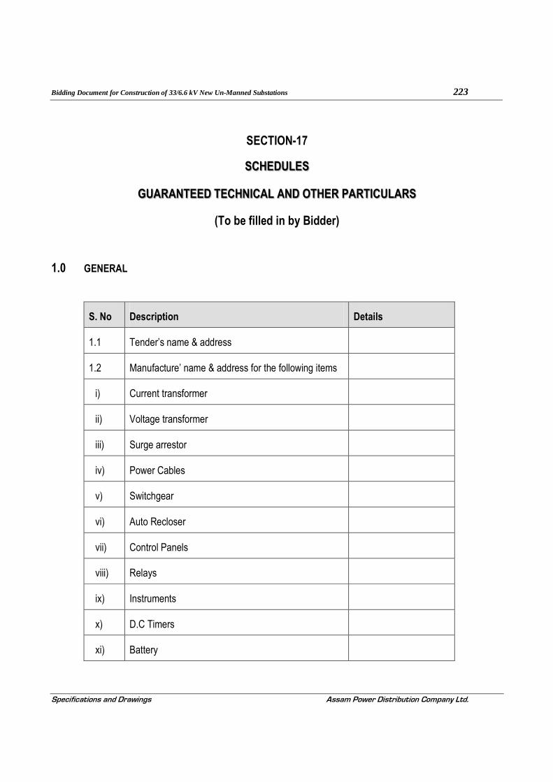
Bidding Document for Construction of 33/6.6 kV New Un-Manned Substations 223
Specifications and Drawings Assam Power Distribution Company Ltd.
SECTION-17
SCHEDULES
GUARANTEED TECHNICAL AND OTHER PARTICULARS
(To be filled in by Bidder)
1.0 GENERAL
S. No Description Details
1.1 Tender’s name & address
1.2 Manufacture’ name & address for the following items
i) Current transformer
ii) Voltage transformer
iii) Surge arrestor
iv) Power Cables
v) Switchgear
vi) Auto Recloser
vii) Control Panels
viii) Relays
ix) Instruments
x) D.C Timers
xi) Battery

Bidding Document for Construction of 33/6.6 kV New Un-Manned Substations 224
Specifications and Drawings Assam Power Distribution Company Ltd.
xii) Battery Charger
xiii) Other accessories
1.3 Climatic condition for which the technical parameters
are guaranteed
i) Altitude
ii) Ambient Temperature (Max & Min)
iii) Average rainfall per annum
iv) Max. humidity
1.4 Tenderer’s proposal no. & date
1.5 Name and address of tenderer’s representative from whom technical clarification can be obtained

Bidding Document for Construction of 33/6.6 kV New Un-Manned Substations 225
Specifications and Drawings Assam Power Distribution Company Ltd.
Guaranteed Technical Particulars
2.0 GUARANTEED TECHNICAL PARTICULARS OF 33kV /6.6kV TRANSFORMER
(To be filled by bidder)
Sl. No
Description
1 Name of the Manufacturer
2 Installation [indoor/outdoor]
3 Reference standards
4 Continuous Ratings
a) Type of cooling
b) Rating [MVA]
c Rated voltage
i HV [KV rms.]
ii LV [KV-rms.]
d Highest system voltage
i HV [KV rms.]
ii LV [KV-rms.]
e Rated frequency with ±% variation
f Number of phases
g Current at rated full load and on principal tap
i HV [Amps]
ii LV [Amps]
5 Connections
HV

Bidding Document for Construction of 33/6.6 kV New Un-Manned Substations 226
Specifications and Drawings Assam Power Distribution Company Ltd.
Sl. No
Description
LV
6 Connection symbol and vector group
7 Temperature rise
a Temperature rise of oil above reference peak ambient temperature i.e.50 °C [by thermometer] [°C]
b Temperature rise of winding above reference peak ambient temperature
[by resistance method][°C]
c Temperature gradients between windings & oil.
d Limit of Hot spot temperature for which the Transformer is designed [°C]
8 Type of OFF load tap changing switch
9 Tapping on windings for
i Constant flux/variable flux/combined
regulation
ii Tapping provided at
iii Number of steps
iv Range of tapping for variation [+ percent to - percent]
10 i No load loss at rated voltage and frequency at principal tap [KW]
ii No load loss at the voltage corresponding to highest tap [KW]
11 Load loss at rated output, rated frequency, corrected for 75 °C winding temperature at:- [Copper loss ]
ONAN
i Principal tap [In KW]

Bidding Document for Construction of 33/6.6 kV New Un-Manned Substations 227
Specifications and Drawings Assam Power Distribution Company Ltd.
Sl. No
Description
ii Highest tap [In KW]
iii Lowest tap [In KW]
12 Positive sequence impedance on rated MVA base at rated current and frequency at 75°Centigrade winding temperature at
i Principal tap [%]
ii Highest tap [%]
iii Lowest tap [%]
13 Zero sequence impedance at reference
temperature of 75°C at principal tap [%]
14 % reactance at rated MVA base at rated
current and rated frequency at
i Principal tap [%]
ii Highest tap [%]
iii Lowest tap [%]
15 % resistance at rated MVA base at rated current and rated frequency at
i Principal tap [%]
ii Highest tap [%]
iii Lowest tap [%]
16 % Impedance at rated MVA base at rated
current and rated frequency at
i Principal tap [%]
ii Highest tap [%]
iii Lowest tap [%]
17 a Polarisation index i.e. ratio of Megger values at 600 In Between PI

Bidding Document for Construction of 33/6.6 kV New Un-Manned Substations 228
Specifications and Drawings Assam Power Distribution Company Ltd.
Sl. No
Description
secs to 60 secs, (H.V. to E, L.V. to E, & H.V.to L.V.) H.V - E
L.V. - E
H.V – L.V.
b Regulation at full load and 75°C winding temperature expressed as a percentage of normal voltage
i At unity power factor [%]
ii At 0.8 power factor [lagging][%]
18 Efficiency at 75°C winding temperature as derived from guaranteed loss figures and at
Unity power
factor
0.8 Power
factor
a At full load [%]
b At ¾ load [%]
c At ½ load [%]
19 i Maximum efficiency [%]
ii Load at which maximum efficiency occurs[% of full load]
20 Short time thermal rating of
i HV winding in KA and duration in seconds
ii LV winding in KA and duration in seconds
21 Permissible over loading:-
a HV winding
b LV winding
22 Terminal arrangement
a High voltage [HV]
b Low voltage (LV)
c Neutral

Bidding Document for Construction of 33/6.6 kV New Un-Manned Substations 229
Specifications and Drawings Assam Power Distribution Company Ltd.
Sl. No
Description
23 Insulating and cooling medium
24 Test voltage HV LV
i Lightning impulse withstand test voltage [KVP]
ii Power frequency withstand test voltage [dry and wet][for 1 minute] [KV-rms.]
25 Noise level when energized at normal voltage, frequency without load.
26 External short circuit withstand capacity [MVA] and duration [seconds]
27 Over-fluxing withstand capability of the
Transformer
28 DETAILS OF CORE
a Type of core construction
b Type of corner joints of the core
c Maximum flux density at
i Rated voltage [33/11 KV] & rated frequency 50 Hz][in Tesla]
ii Highest system voltage [36/12 KV] and lowest system frequency [48.5Hz.][in Tesla]
d No load current, no load loss and no load power factor at normal ratio and frequency [Amp/KW/p.f.]
i 10 percent of rated voltage
ii 25 percent of rated voltage
iii 50 percent of rated voltage
iv 85 percent of rated voltage
v 100 percent of rated voltage

Bidding Document for Construction of 33/6.6 kV New Un-Manned Substations 230
Specifications and Drawings Assam Power Distribution Company Ltd.
Sl. No
Description
vi 105 percent of rated voltage
vii 110 percent of rated voltage
viii 112.5 percent of rated voltage
ix 115 percent of rated voltage
x 120 percent of rated voltage
xi 121 percent of rated voltage
xii 125 percent of rated voltage
e Core laminations:-
i Material of core lamination [M4 /HIB]
ii Grade of core laminations
iii Thickness of core lamination [mm]
iv Specific loss [watt/Kg.] at rated voltage and rated frequency
v Specific loss [watt/Kg.] at highest system voltage and lowest system frequency
vi Whether specific core loss graph [flux density vs. watt/Kg. submitted
vii VA/Kg at rated voltage and rated frequency
viii VA/Kg. at highest system voltage and lowest system frequency
ix Whether VA/Kg. Vs. flux density graph Submitted
x Insulation of core laminations
f CORE ASSEMBLY:-
i Core diameter [mm]
ii Core window height [mm]

Bidding Document for Construction of 33/6.6 kV New Un-Manned Substations 231
Specifications and Drawings Assam Power Distribution Company Ltd.
Sl. No
Description
iii Core leg centre [mm]
iv Gross core cross-sectional area [m²]
v Whether details of core widths, stacks and calculation furnished as per enclosed annexure
vi Distance between centers [mm]
vii Total height of core [mm]
viii 1) Details of core belting.
2) Material, grade & type
3) Width
4) Thickness
5) Fixing method
ix Details of top end frame
x Details of Bottom end frame
xi Details of clamp plate [Material, thickness, Insulation]
xii Total core weight [kg]
xiii Core loss basing on core loss graph at operating flux density [rated voltage and rated frequency] [kw]
xiv Core stacking factor
xv Net core area Sq. m.
xvi Margin towards corner joints, cross fluxing etc [kw]
xvii Total core loss at rated voltage and rated frequency [xiii+xvii] [kw]
xviii Dielectric loss at rated voltage and rated frequency [KW]
xix No load loss at rated voltage and rated frequency [xviii+xix] [KW]

Bidding Document for Construction of 33/6.6 kV New Un-Manned Substations 232
Specifications and Drawings Assam Power Distribution Company Ltd.
Sl. No
Description
g Describe location/method of core grounding
h Details of oil ducts in core
i Peak value of magnetizing Inrush current (% of HV rated current).
29 DETAILS OF WINDINGS. HV Regulating LV
a Type of winding
b Material of the winding conductor
c Maximum current density of windings [at rated current] and conductor area
Conductor area [cm²]
Current density
[A/cm²]
i HV
ii Regulating
iii L.V.
d Whether HV windings are interleaved
e Whether windings are pre-shrunk?
f Whether adjustable coil clamps are provided for H.V. and L.V. windings?
g Whether steel rings are used for the windings? If so, whether these are split?
h Whether electrostatic shields are provided to obtain uniform voltage distribution in the windings?
i Winding Insulation. Type & class Graded or
Ungraded
i H.V. & Regulating
ii LV Winding
j Insulating material used for

Bidding Document for Construction of 33/6.6 kV New Un-Manned Substations 233
Specifications and Drawings Assam Power Distribution Company Ltd.
Sl. No
Description
i H.V.& Regulating winding
ii L.V Winding
iii Tapping connection
k Insulating material used between
i H.V. and L.V. winding
ii H.V. and Regulating winding
iii Core and L.V winding
iv L.V. Winding and core
v Regulating Winding and core
vi H.V. winding and core
vii H.V. to H.V. winding [between phases]
l Type of axial coil supports
i H.V. winding
ii Regulating winding
iii LV winding
m Type of radial coil supports
i H.V. winding
ii Regulating winding
ii LV winding
n Maximum allowable torque on coil clamping HV Regulating LV bolts
o Bare conductor size (mm).
p Insulated conductor size (mm).
q No. of conductors in parallel (Nos.).

Bidding Document for Construction of 33/6.6 kV New Un-Manned Substations 234
Specifications and Drawings Assam Power Distribution Company Ltd.
Sl. No
Description
r No. of turns/phase
s No. of discs/phase
t No. of turns/disc
u Gap between discs. (mm).
v Inside diameter (mm).
w Outside diameter (mm).
x Axial height after shrinkage (mm).
y D.C.RESISTANCE
i L.V winding at 75 ° C (Ohms).
ii HV winding and Regulating winding at normal tap at 75° C (Ohms).
iii HV winding and Regulating winding at highest tap at 75° C (Ohms).
iv HV winding and regulating winding at lowest tap. (Ohms).
v Total I²R losses at 75 ° C. for normal tap. (KW).
vi Total I²R losses at 75 ° C. for highest tap. (KW)
vii Total I²R losses at 75 ° C for lowest tap.(KW).
viii Stray losses including eddy current losses in winding at 75°C (KW).
a Normal tap position
b Highest tap position
c Lowest tap position.
d Any special measures taken to reduce eddy current losses and stray losses, mention in details

Bidding Document for Construction of 33/6.6 kV New Un-Manned Substations 235
Specifications and Drawings Assam Power Distribution Company Ltd.
Sl. No
Description
x Load losses at 75°C [I²R + stray].
a Normal tap position [KW].
b Highest tap position [KW].
c Lowest tap position [KW].
z Details of special arrangement provided to improve surge voltage distribution in the windings
30 BUSHINGS. HV LV Neutral
a Make and type
i Rated voltage class [KV-rms.]
ii Rated current [Amps.]
b Lightning Impulse withstand test voltage [1.2/50 micro second][KVP]
c Power frequency withstand test voltage
i Wet for 1 minute [KV-rms]
ii Dry for 1 minute [KV-rms]
d Power frequency visible corona discharge voltage [KV-rms.]
e Minimum creepage distance in mm
f Phase to earth clearance in air of live parts at the top of bushings
31 Minimum clearance [mm] In Oil Out of Oil
Between windings
Phase to Ground
Between windings
Phase to Ground
HV
LV
32 Weight [Tolerance + 5%]

Bidding Document for Construction of 33/6.6 kV New Un-Manned Substations 236
Specifications and Drawings Assam Power Distribution Company Ltd.
Sl. No
Description
[Approximate value is not allowed]
a Core [Kg.]
b Core with clamping [Kg.]
c H.V. winding insulated conductor [Kg.]
d Regulating winding insulated conductor [Kg.]
e L.V.winding insulated conductor [Kg.]
f Coils with insulation [Kg.]
g Core and winding [Kg]
h Oil required for first filling [Liter/Kg.]
i Tank and fittings with accessories [Kg.]
j Untanking weight [Kg.]
k Total weight with oil and fittings [kg.]
33 DETAILS OF TANK
a Material for Transformer tank
b Type of tank
c Thickness of sheet
[No approximate value to be mentioned]
i Sides [mm]
ii Bottom [mm]
iii Cover [mm]
iv Radiators [mm]
d Inside dimensions of main tank
[No approximation in dimensions to be used]
i Length [mm]

Bidding Document for Construction of 33/6.6 kV New Un-Manned Substations 237
Specifications and Drawings Assam Power Distribution Company Ltd.
Sl. No
Description
ii Breadth [mm]
iii Height [mm]
e Outside dimensions of main tank
[No approximation in dimensions to be used]
i Length [mm]
ii Breadth [mm]
iii Height [mm]
f Thickness of spray galvanisation of tank bottom.
g Vacuum recommended for hot oil circulation [torr]
h Vacuum to be maintained during oil filling in Transformer tank [torr]
i Vacuum to which the tank can be subjected without distortion [torr]
j No. of bi-directional wheels provided
k Track gauge required for the wheels
i Transverse axis
ii Longitudinal axis
l Type and make of pressure relief device and minimum pressure at which it operates [Kpa]
34 CONSERVATOR
a Total volume [Liters]
b Volume between the highest and lowest visible oil levels [Litres]
c Whether flexi separator provided
35 OIL QUALITY

Bidding Document for Construction of 33/6.6 kV New Un-Manned Substations 238
Specifications and Drawings Assam Power Distribution Company Ltd.
Sl. No
Description
a Governing standard
b Density in gms/cu-cm
c Kinematics viscosity in CST
d Inter facial tension at 27°C in N/m
e Flash point in °C
f Pour point in °C
g Acidity [neutralization value] in mg of KOH/gm
h Corrosive sulfur in %
i Electric strength [breakdown voltage]
i As received [KV-rms.]
ii After treatment [KV-rms.]
j Dielectric dissipation factor [tan delta] at 90°C
k Saponification value in mg of KOH/gm
l Water content in ppm
m Specific resistance
i At 90°C [ohm-cm]
ii At 27 °C [ohm-cm]
N- dm analysis
CA%
CM%
CP%
o Oxidation stability
i Neutralization value after oxidation
ii Total sludge after oxidation

Bidding Document for Construction of 33/6.6 kV New Un-Manned Substations 239
Specifications and Drawings Assam Power Distribution Company Ltd.
Sl. No
Description
p Characteristic of oil after ageing test as per ASTMD-1934
i Specific resistance at
27°C [ohm-cms]
90°C [ohm-cms]
ii Tan delta
iii Sludge content
iv Neutralization number
v Details of oil preserving equipment offered
36 RADIATORS
a Overall dimensions lxbxh [mm]
b Total weight with oil [Kg.]
c Total weight without oil [Kg.]
d Thickness of radiator tube [mm]
e Types of mounting
f Vacuum withstand capability
g Total radiating surface in sq.m
h Type and make of material used for the radiators
i Total number of radiators for
Transformer and dimensions of tubes
j Thickness of hot dip galvanization of radiators
37 GAS AND OIL OPERATED RELAY
a Make
b Type

Bidding Document for Construction of 33/6.6 kV New Un-Manned Substations 240
Specifications and Drawings Assam Power Distribution Company Ltd.
Sl. No
Description
c Size
d Whether supervisory alarm and trip contacts provided and their sizes and Nos
38 TEMPERATURE INDICATORS Oil Temp
Indicator
Winding Temp
Indicator
a Make and type
b Permissible setting ranges for alarm and trip
c Number of contacts
d Current rating of each contact
e Whether supervisory alarm contacts provided?
f Size [lxbxd]
g Nos.
h Ratio and type of CT used for winding temperature indicators.
39 APPROXIMATE OVERALL DIMENSIONS OF TRANSFORMER INCLUDING COOLING SYSTEM, TAP CHANGING GEAR ETC.
Length [mm]
Breadth [mm]
Height [mm]
40
a Minimum clearance height for lifting core and winding from tank [mm]
b Minimum clearance height for lifting tank cover [mm]
41 SHIPPING DETAILS
a Approximate weight of heaviest package [Kg.]

Bidding Document for Construction of 33/6.6 kV New Un-Manned Substations 241
Specifications and Drawings Assam Power Distribution Company Ltd.
Sl. No
Description
b Approximate dimensions of largest Package [Kg.]
42 Transformers will be transported with oil/gas.
43 MARSHALLING KIOSK
a Make and type
b Details of apparatus proposed to be housed in the kiosk
44 Details of anti-earthquake device provided, if any
45 Separate conservator and Buchholz relay provided
46 TAP CHANGING EQUIPMENT
[These details refer to the basic rating of O.L. T.C. as guaranteed by OLTC manufacturers]
a Make
b Type
c Power flow [Uni.-directional/bi -
directional/restricted bi-directional]
d Rated voltage to earth [KV]
e Rated current [Amps.]
f Step voltage [volts]
g Number of steps
h Control - manual/local- electrical/remoteelectrical
i Voltage control [Automatic/Non -automatic]
j Line drop compensation provided/not provided
k Parallel operation
l Protective devices
m Auxiliary supply details
n Time for complete tap change [one step][Sec.]

Bidding Document for Construction of 33/6.6 kV New Un-Manned Substations 242
Specifications and Drawings Assam Power Distribution Company Ltd.
Sl. No
Description
o Diverter selector switch transient time [cycles]
p Value of maximum short circuit current [Amps]
q Maximum impulse withstand test voltage with 1.2/50 micro seconds full wave between switch
assembly and ground [KVP]
r Maximum power frequency test voltage between switch assembly and earth [KV-rms]
s Maximum impulse withstand test voltage with 1.2/50 micro-seconds across the tapping range [KVP]
t Approximate overall dimensions of tap changer [WxBxD] in mm
u Approximate overall weight [Kg.]
v Approximate mass of oil [Kg.]
w Particulars of the OLTC control panel for installation in control room
47 DRIVING MECHANISM BOX
a Make and type
b Details of apparatus proposed to be housed in the box
48 Types of terminal connectors and drawing No
a HV
b LV
49 Details of painting, galvanization conforms to this Specification [Yes/No]
50 Type of oil level indicator and whether Supervisory alarm contact for low oil level provided [Yes/No]
51 Type and size of thermostat to be used
52 No. of breathers provided [Nos.]

Bidding Document for Construction of 33/6.6 kV New Un-Manned Substations 243
Specifications and Drawings Assam Power Distribution Company Ltd.
Sl. No
Description
53 Type of dehydrating agent used for breathers
54 Valve sizes and numbers
a Drain valves- mm-Nos
b Filter valves- mm-Nos
c Sampling valves- mm-Nos
d Radiator valves- mm-Nos
e Other valves- mm-Nos
55 a Type and make of PRV
b No. of each type of devices per transformer
c Min. pressure at which device operates
56 Please enclose the list of accessories and fittings, being provided on transformer. Please confirm, these are as stipulated in the tender
57 Whether the transformer, covered is fully type tested and if so, whether copies of type test certificates, enclosed with the tender
58 Please confirm that you will guarantee maximum Impedance variation between phases within the limit of 2% only

Bidding Document for Construction of 33/6.6 kV New Un-Manned Substations 244
Specifications and Drawings Assam Power Distribution Company Ltd.
3.0 AUTO RECLOSER
(This Schedule shall be filled in for each category of AR)
Sl No Description To be filled up by the Bidder
1 Name of Manufacturer & address
2 Place of manufacture
3 Construction
a) Interrupter medium
b) Type of enclosure
c) Insulating medium
4 Installation
5 Operation
6 System voltage
7 Highest system voltage
8 Normal current
a) For transformer breaker
b) For line breaker
9 Short time withstand current & duration
a) For transformer breaker
b) For line breaker
10 Making current
a) For transformer breaker
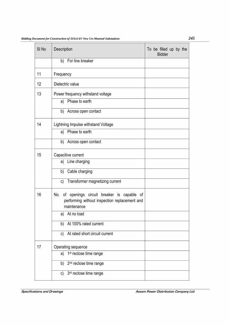
Bidding Document for Construction of 33/6.6 kV New Un-Manned Substations 245
Specifications and Drawings Assam Power Distribution Company Ltd.
Sl No Description To be filled up by the Bidder
b) For line breaker
11 Frequency
12 Dielectric value
13 Power frequency withstand voltage
a) Phase to earth
b) Across open contact
14 Lightning Impulse withstand Voltage
a) Phase to earth
b) Across open contact
15 Capacitive current
a) Line charging
b) Cable charging
c) Transformer magnetizing current
16 No. of openings circuit breaker is capable of performing without inspection replacement and maintenance
a) At no load
b) At 100% rated current
c) At rated short circuit current
17 Operating sequence
a) 1st reclose time range
b) 2nd reclose time range
c) 3rd reclose time range

Bidding Document for Construction of 33/6.6 kV New Un-Manned Substations 246
Specifications and Drawings Assam Power Distribution Company Ltd.
Sl No Description To be filled up by the Bidder
18 Type of operating mechanism
a) Closing
b) Opening
19 Terminal bushing
a) Material
b) Creepage distance
c) String length
20 Interrupter housing
21 Energy stored in a fully charged condition
a) Closing
b) Opening
22 Timings
a) Closing
b) Opening
c) Close-Open (CO)
23 Total length of stroke of mechanism
24 Type of contact in interrupter
25 Material of contact
26 Contact pressure at no load ( closed condition of CB)
27 Temperature rise of contact for 50o C ambient
28 Mass of the Auto Recloser (Approx)
a) Base Structure with operating mechanism

Bidding Document for Construction of 33/6.6 kV New Un-Manned Substations 247
Specifications and Drawings Assam Power Distribution Company Ltd.
Sl No Description To be filled up by the Bidder
b) Mechanism
c) Cabinet
d) Total Mass
29 Protection class for cabinet
30 Corrosion protection for cabinet
31 Corrosion protection for Structure
32 Auxiliary contacts
a) IO point with expander card
b) NO & NC contacts
c) Convertibility of contacts
d) Breaking current DC and inductive circuit at 110 V DC resp at L/R= 25 ms.
e) Breaking current AC and PF=0.8 at 230 VAC
33 Maximum load on foundations ( inclusive of the mass of the circuit breaker)
a) Compression (Open operation)
b) Tension ( Close operation)
34 Altitude above MSL (max)
35 Altitude above MSL (max)
36 Wind pressure
37 Closing coil details
a) Rated voltage
b) Operating range

Bidding Document for Construction of 33/6.6 kV New Un-Manned Substations 248
Specifications and Drawings Assam Power Distribution Company Ltd.
Sl No Description To be filled up by the Bidder
38 Opening coil details
a) Rated voltage
b) Operating range
39 Auxiliary transformer details
a) Standard Ratio
b) Class of accuracy
c) Rated burden
d) Installation
40 CVT
a) Standard Ratio
b) Class of accuracy
c) Rated burden
d) Installation
41 Short Circuit breaking capacity
a) Terminal Fault
b) Out of phase
42 DC component
43 Details of protective systems employed
44 Details of communication systems employed (Should be annexed in detail)
4.0 CURRENT TRANSFORMERS (OUTDOOR)
(This Schedule shall be filled in for each category of CT)

Bidding Document for Construction of 33/6.6 kV New Un-Manned Substations 249
Specifications and Drawings Assam Power Distribution Company Ltd.
S. No Description UNIT PARTICULARS
1.0 Name of the Manufacturer
2.0 Country of Origin
3.0 Manufacture’s type and Designation
4.0 Standards Applicable
5.0 Type of installation
6.0 Windings:
A). Primary Winding
(i) Material
(ii) Design density for short circuit current.
(iii) Conductivity of metal used.
(iv) Area of cross section.
B). Secondary Winding
(i) Material
(ii) Area of cross section.
7.0 Rated primary voltage KV
8.0 Rated frequency Hz
9.0 Rated primary current Amps
10.0 Rated secondary current Amps

Bidding Document for Construction of 33/6.6 kV New Un-Manned Substations 250
Specifications and Drawings Assam Power Distribution Company Ltd.
S. No Description UNIT PARTICULARS
11.0 Ratio taps (on secondary side only)
12.0 Type of insulation
13.0 RIV at 1.1 x Rated voltage mV
14.0 Tank material and Tank coating
15.0 Porcelain housing and it make (Single piece only)
16.0 Sealing (Metal Bellow) provided
17.0 Acceptable limit of temperature
18.0 Acceptable partial discharge level at 1.1 times the rated voltage
19.0 (i) Rated short time withstand Current
(ii) Duration of above rated short time current
KA
Second
20.0 Rated dynamic withstand current kAp
21.0 Rated continuous thermal current pu
22.0 1.2/50 micro-second impulse withstand voltage.
kVp
23.0 One minute power frequency withstand voltage of primary winding (Dry)
kV rms
24.0 One minute power frequency dry. Withstand voltage secondary
KV rms

Bidding Document for Construction of 33/6.6 kV New Un-Manned Substations 251
Specifications and Drawings Assam Power Distribution Company Ltd.
S. No Description UNIT PARTICULARS
winding.
25.0 (a) Minimum total creepage distance of insulator bushing
(b) Protected creapage of distance of bushing
mm
mm
26.0 Details of Core
(Core details to be given for each current ratio)
(i) Current Ratio
(ii) Output burden VA
(iii) Class of accuracy
(iv) Accuracy limit factor
(v) Instrument Security Factor
(vi) Min. knee point voltage V
(vii) Max. Secondary resistance corrected to 75 deg.C
ohm
(viii) Max. exciting current at
20% of knee point voltage
50% of knee point voltage
100% of knee point voltage
mA

Bidding Document for Construction of 33/6.6 kV New Un-Manned Substations 252
Specifications and Drawings Assam Power Distribution Company Ltd.
S. No Description UNIT PARTICULARS
27.0 Weight of oil ( Kg.
28.0 Total Weight Kg.
29.0 Mounting details
30.0 Overall dimensions
31.0 Characteristics (whether graphs enclosed)
a. Ratio and phase angle curves
b. Magnetisation curves
c. Ratio correction factor curves
32.0 Core
a) Area of cross section
b) Flux density at rated primary current and rated burden.
5.0 POTENTIAL TRANSFORMER
(This Schedule shall be filled in for each category of PT)
S. No Description UNIT PARTICULARS
33/√3KV/110/√3V
11/√3KV/110/√3V
1.0 Name of the Manufacturer

Bidding Document for Construction of 33/6.6 kV New Un-Manned Substations 253
Specifications and Drawings Assam Power Distribution Company Ltd.
S. No Description UNIT PARTICULARS
33/√3KV/110/√3V
11/√3KV/110/√3V
2.0 Country of Origin
3.0 Manufacture’s type and Designation
4.0 Standards Applicable
5.0 Type of installation (outdoor)
6.0 Mounting of tank (Bottom)
7.0 Rated primary voltage KV
8.0 Secondary Winding Details Wdg-1
(i) No of Secondary Winding
(ii) Rated secondary voltage V
(iii) Rated burden VA
(iv) Class of accuracy
9.0 Maximum ratio error with % rated burden and 5% normal primary voltage.
10.0 Maximum phase angle error % with rated burden and 5% normal primary voltage.
11.0 Temperature rise at 1.1 times rated voltage with rated burden
0C
12.0 Rated voltage factor and time.

Bidding Document for Construction of 33/6.6 kV New Un-Manned Substations 254
Specifications and Drawings Assam Power Distribution Company Ltd.
S. No Description UNIT PARTICULARS
33/√3KV/110/√3V
11/√3KV/110/√3V
13.0 Impulse withstands test voltage. kV (peak)
14.0 One minute power frequency withstand test voltage on primary
kV rms
15.0 One minute power frequency withstand test voltage on secondary
KV rms
16.0 Total creepage distance of the bushing
mm
17.0 Protected creepage distance of the bushing
mm
18.0 Sealing (Metal Bellow) provided
19.0 Quantity of insulating oil Litres
20.0 Weight of oil Kg.
21.0 Total weight including oil Kg
22.0 Mounting details
23.0 Overall dimensions
6.0 RTU
S. No
Description Details

Bidding Document for Construction of 33/6.6 kV New Un-Manned Substations 255
Specifications and Drawings Assam Power Distribution Company Ltd.
S. No
Description Details
1.0 RTU
1.1 Manufacture’ name & address for the following items
1.2 RTU - Make and Type
i) Processor module microprocessor type
ii) IEC60870-5 101 Slave protocol supplied - interoperability table document supplied
iii) IEC60870-5 103 Master protocol supplied - interoperability table document supplied
iv) MODBUS RTU Master protocol supplied - interoperability table document supplied
v) DNP3.0 Master protocol supplied – interoperability table document supplied
vi) RTU Programming Software and accessories supplied
vii) Ability to add software applications to processor module (i.e. automation logic, protocols)*
viii) Ability to expand RTU by adding hardware*
ix) Ability to configure and download configuration remotely*
x) Hardware/software - Number of analog inputs (max )
xi) Hardware/software - Number of digital inputs (max)
xii) Hardware/software - Number of counter inputs (max)

Bidding Document for Construction of 33/6.6 kV New Un-Manned Substations 256
Specifications and Drawings Assam Power Distribution Company Ltd.
S. No
Description Details
xiii) Hardware/software - Number of digital control outputs (max)
xiv) DC Analog Input:
a. Input voltage/current range
b. Input impedance
c. Number of inputs per card supplied
d. A/D converter:
e. Method
f. Output code (bits plus sign bit)
g. Offset adjustment range
h. Ability to reconfigure by software
i. Quantising error
j. Maximum input offset
k. Maximum scale factor error
l. Maximum relative accuracy
m. Max conversion time (less multiplex time)
xv) AC Analog Input
a. Nominal and max input voltage range
b. Nominal and max Input current range
c. Input impedance

Bidding Document for Construction of 33/6.6 kV New Un-Manned Substations 257
Specifications and Drawings Assam Power Distribution Company Ltd.
S. No
Description Details
d. Number of inputs per card supplied (PT/CT)
e. A/D converter:
f. Output code (bits plus sign bit)
g. Offset adjustment range
h. Ability to reconfigure by software
i. Self-calibration
j. Sampling rate
k. Accuracy in % of nominal
l. List of derivative points calculated
m. List of energy counters calculated
n. Configurable options – correction factors for PTs and CTs, voltage L-L/L-N, current flow direction, line frequency filter, zero-clamping
xvi) Digital Input
a. Maximum Number
b. Number of Inputs per card supplied
c. Contact wetting options and voltages
d. Types Accepted
e. Ability to reconfigure by software
f. Software configurable options – debounce filtering, chattering filtering, single/double status, invert status, COS/SOE generation

Bidding Document for Construction of 33/6.6 kV New Un-Manned Substations 258
Specifications and Drawings Assam Power Distribution Company Ltd.
S. No
Description Details
g. SOE time stamp resolution
h. Input Impedance
i. Time delay
j. Isolation withstand
k. Transient Voltage Withstand
xvii) Digital Output
a. Maximum Number
b. Number of Outputs per card supplied
c. Trip/Close, Raise/Lower, Latching modes
d. Self-checking failure protection
e. Local/Remote switch per module
f. Interposing relays required
g. Relay contact rating (V and I)
h. Relay contact configuration
i. Ability to reconfigure by software
j. Software configurable options
xviii) Analog Output module available*
xix) Combination module (DI / AI / DO / AO)
available*
xx) Maintenance facility type of terminal supplied

Bidding Document for Construction of 33/6.6 kV New Un-Manned Substations 259
Specifications and Drawings Assam Power Distribution Company Ltd.
S. No
Description Details
xxi) Local HMI displays available*
xxii) Modem
a. CCITT standards supplied
b. Communication data rates supplied
c. Modulation supplied
d. 2 or 4 wire communication lines mode supplied
e. Receive level adjustable range
f. Transmit level adjustment range
g. Mounting arrangement
h. Power input required (V and W)
xxiii) RS232 to RS485 converter for IEDs interface
xxiv) RTU dimensions
a. Height
b. Width
c. Depth
d. Weight
xxv) Climatic condition for which the technical
parameters are guaranteed
a) Altitude
b) Ambient Temperature (Max & Min)

Bidding Document for Construction of 33/6.6 kV New Un-Manned Substations 260
Specifications and Drawings Assam Power Distribution Company Ltd.
S. No
Description Details
c) Average rainfall per annum
d) Max. humidity
2.0 COMMUNICATION TEST SET
2.1 Manufacture’ name & address for the following
items
2.2 Test set - make and type
2.3 Protocols supplied (all standard requests,
commands, replies and objects supported)
i) IEC60870-5-101
ii) IEC60870-5-103
iii) MODBUS
iv) DNP3
v) Master simulation
vi) Slave simulation
vii) Monitoring of communication exchanges
viii) Single/continuous transmission of messages
1.8 Modem compatible with RTU modem supplied
1.9 Display
i) Dynamic data values displayed
ii) Exchanges captured and stored in files for
analysis
iii) Messages displayed in row (hexadecimal) and

Bidding Document for Construction of 33/6.6 kV New Un-Manned Substations 261
Specifications and Drawings Assam Power Distribution Company Ltd.
S. No
Description Details
interpreted format
1.10 Bidder’s proposal no. & date
1.11 Name and address of bidder’s representative
from whom technical clarification can be obtained
7.0 CONTROL AND RELAY PANELS
Sl. No. Technical Particulars Unit To be filled by the bidder
1.0 GENERAL
1.1 Panel sheet thickness
1.2 Over all dimensions
i) Width
ii) Depth
iii) Height
1.3 Total weight of panel
1.4 Internal finish
1.5 External finish
2.0 PROTECTIVE RELAYS
2.1 Numeric over current / Earth fault relays
a) Type

Bidding Document for Construction of 33/6.6 kV New Un-Manned Substations 262
Specifications and Drawings Assam Power Distribution Company Ltd.
Sl. No. Technical Particulars Unit To be filled by the bidder
b) Current coil range
c) Tap range
d) Power consumption
i) Highest tap
ii) Lowest tap
e) Time of operation at maximum time dial setting
f) Type of characteristic
g) Whether draw out type or not
h) Trip contact rating Amps
i) Whether seal in contact provided or not
j) Is the slope setting variable?
k) Disturbance recorder capacity in time duration
l) Number of event recording
m) Does it have LBB protection
n) Does it have frequency protection, describe
o) Does it have voltage protection, describe
p) Protocol used; Details to be given
q) Nos. of communication ports; Details to be given
2.2 Numeric Differential Relays
a) Manufacturer’s Name & address

Bidding Document for Construction of 33/6.6 kV New Un-Manned Substations 263
Specifications and Drawings Assam Power Distribution Company Ltd.
Sl. No. Technical Particulars Unit To be filled by the bidder
b) Type
c) Current coil Rating
d) Tap Range
e) Maximum VA burden at:-
(i) Operating coil
(ii) Restraining coil.
f) Is the slope setting variable?
g) Harmonic restraint provided or not.
h) Range of HT/LT ratios over which the relay can be used.
i) Operating time
j) Trip contact rating.
k) Whether sealed in contact provided or not.
l) Does it have over fluxing feature
m) Disturbance recorder capacity in time duration
n) Number of event recording
o) Does it have REF functions
p) Does it have O/C & E/F protection
q) Does it have LBB protection
r) Does it have frequency protection
s) Does it have voltage protection
t) Disturbance recorder capacity in time duration

Bidding Document for Construction of 33/6.6 kV New Un-Manned Substations 264
Specifications and Drawings Assam Power Distribution Company Ltd.
Sl. No. Technical Particulars Unit To be filled by the bidder
u) Number of event recording
r) Protocol used; Details to be given
s) Nos. of communication ports; Details to be given
2.3 Auxiliary Relays
a. Manufacturer’s Name & address
b. Type
c. Rated current/voltage and permissible variation
d. Rated burden
e. No. and type of contacts (whether ‘NO’ or ‘NC’)
f. Rating of contacts
g. Total operating time of relays
h. One minute power frequency withstand voltage
i. Detailed literature furnished with reference (Yes/No)
j. Details of testing facilities provided
2.4 D.C. Timers
a. Type
b. Rated operating voltage

Bidding Document for Construction of 33/6.6 kV New Un-Manned Substations 265
Specifications and Drawings Assam Power Distribution Company Ltd.
Sl. No. Technical Particulars Unit To be filled by the bidder
c. Permissible operation voltage
i) Minimum
ii) Maximum
iii) Error on the time to c (i)
iv) Error on the time to c (ii)
d. Rated burden
e. Setting range and taps
f. One minute power frequency withstand voltage
g. No. and type of contacts
h. Rating of contacts (current and voltage)
i. Detailed literature furnished with reference
j. Details of testing facilities provided
2.5 Control Wiring (panel
Material and size of conductor
a) for CT circuit
b) for other circuit
2.6 Number of stranded in conductor
2.7 Tinned/untinned
2.8 Material of insulation and sheath
2.9 Voltage grade of control wiring
2.10 Numbered ferrules at both ends

Bidding Document for Construction of 33/6.6 kV New Un-Manned Substations 266
Specifications and Drawings Assam Power Distribution Company Ltd.
Sl. No. Technical Particulars Unit To be filled by the bidder
2.11 Terminals
a) Make
b) Current rating
c) Clamp type or bolt type
d) Maximum conductor size and number of conductor which it can receive
e) Disconnecting type of CT circuit
f) Terminal making facility provided
g) Crimp type connectors provided at the terminals
h) Spare terminals
8.0 GANG OPERATED SWITCH (ISOLATORS)
(This Schedule shall be filled in for each category of Isolator)
S No. Description Unit Particulars
33KV 11KV
1.0 Name of manufacturer and Address
2.0 Manufacturer’s type
3.0 Standards to which the equipment conforms
4.0 Frequency (Hz)
5.0 Rated voltage KV rms)
6.0 Maximum design voltage at which the isolator can operate (KV rms)
7.0 Continuous current rating (Amp. Rms)

Bidding Document for Construction of 33/6.6 kV New Un-Manned Substations 267
Specifications and Drawings Assam Power Distribution Company Ltd.
S No. Description Unit Particulars
33KV 11KV
8.0 Rated short time current
i) for 3 sec. (KV rms)
ii) rated peak short time current (KA peak)
9.0 Current density at the min. cross section of (Amp./Sq.mm)
i) Moving blades
ii) Terminal pad
iii) Contacts
iv) Terminal connector
10.0 Derating factor for specified site conditions
11.0 Insulation levels
i) Dry impulse withstand voltage (KV peak)
a) Phase to earth
b) Isolating distance
ii) Wet power freq. Withstand voltage (KV
rms)
a) Phase to earth
b) Isolating distance
12.0 Min. clearance in air (mm)
i) Center to center distance between poles
ii) Between live parts & earth

Bidding Document for Construction of 33/6.6 kV New Un-Manned Substations 268
Specifications and Drawings Assam Power Distribution Company Ltd.
S No. Description Unit Particulars
33KV 11KV
iii) Between poles on one phase
13.0 Design & construction
i) No. od insulatiors per pole
ii) No. of break per pole
a) Main switch
b) Earth switch
iii) Type of opening /closing mechanism
iv) Contacts
a) Materials & grade
b) Thickness of silver plating on contact
surface
c) Effective cross sectional area (Sq.mm)
1) Main switch
2) Earth switch
d) No. of operations the isolator can make
without deterioration of contacts
9.0 SURGE ARRESTOR
(This Schedule shall be filled in for each category of LA)
Sl.no Particulars 33KV 11KV

Bidding Document for Construction of 33/6.6 kV New Un-Manned Substations 269
Specifications and Drawings Assam Power Distribution Company Ltd.
Sl.no Particulars 33KV 11KV
1. Name & Address of Supplier & Manufacturer
Surge Arrestor
Surge Monitor
Line Dis-connector
Metal Oxide Block
Terminal Clamp
2. Name & address of collaborator, if any
3. Standard to which surge arrestors conforms
4. Surge Arrestor
4.1 Voltage rating (KV rms)
4.2 Continuous Operating Voltagte (KV rms)
a) Continuous Operating Voltage (KV rms)
b) Leakage current at continuous operation voltage
c) Partial discharge at 1.05 COV (PC)
d) Permitted leakage current of arrestor beyond which arrestor is faulty :
5. Frequency (Hz)
6. Nominal discharge current (wave shape – 8 / 20 micro second) (KA)
7. Pressure relief rated current (KA rms)
8. Steep current protection level at 10 KA
a) Lighting impulse protection level at 5 KA

Bidding Document for Construction of 33/6.6 kV New Un-Manned Substations 270
Specifications and Drawings Assam Power Distribution Company Ltd.
Sl.no Particulars 33KV 11KV
and 10 KA (KVP)
b) Switching impulse protection level with 40 x 80 micro-sec. Wave at 500/1000 A
9. Long duration current impulse withstand capacity and virtual duration
10. Line discharge class
11. Thermal runaway limit of arrestor
12. Energy capability (kJ/KV)
13. Pressure relief rating
14. Dry arcing distance
15. Reference current and reference voltage
16. Arrestor housing
16.1 Power frequency one minute wet withstand voltage (kV rms)
16.2 Lighting impulse dry withstand voltage (KVP)
16.3 Creepage distance
a) Protected
b) Total
16.4 Short circuit withstand capacity
16.5 Bending moment (mm)
17. Dis-connector
a) Constructional Details
b) Other information as applicable to surge

Bidding Document for Construction of 33/6.6 kV New Un-Manned Substations 271
Specifications and Drawings Assam Power Distribution Company Ltd.
Sl.no Particulars 33KV 11KV
arrestor
18. Surge monitor
a) Constructional details
b) Degree of protection
19. Suitable for hot line washing
20. Dimension & weight
21. G A drawing indicating height of complete unit from base to line, minimum recommended center to center spacing, clearance form ground equipment at various height of arrestor, earthing arrestor, earthing arrangement on earthed site of arrestor etc.
22. Details of packing
23. Licence number and date for using ISI certification mark if any
24. Ammeter for discharge current
a) Type & Make
b) Accurancy
c) Range (mA)
25. Residual voltage
26. Follow current
27. Any other information
10.0 BATTERY

Bidding Document for Construction of 33/6.6 kV New Un-Manned Substations 272
Specifications and Drawings Assam Power Distribution Company Ltd.
Sl. No. Description Particulars
1. Name & Address of Supplier & Manufacturer
2. Manufacturer’s type designation
3. Capacity in ampere hour (at 27° C, C10 to 1.75 ECV)
4. Nominal cell voltage (volts)
5. No. of cells
6. Capacity at different rates of discharge
1 hour
(b) 2hour
(c) 3 hour
(d) 5 hour
(e) 8 hour
7. Ah efficiency
8. Wh efficiency
9. Self discharge per week
10. Cyclic life of the battery @ 27° C
11. Service life expectancy
12. Recommended Maximum period of storage
13. Positive Plates
(a) No of plate per cell
(b) Type of plate
(c) Total surface area of plate
(d) Grid Material

Bidding Document for Construction of 33/6.6 kV New Un-Manned Substations 273
Specifications and Drawings Assam Power Distribution Company Ltd.
Sl. No. Description Particulars
14. Negative Plates
(a) No of plate per cell
(b) Type of plate
(c) Total surface area of plate
(d) Grid Material
15. Material of Container
16. Type of separator
17. Terminal
18. Safety valve Opening pressure -Closing pressure -
19. Painting Battery racks
20. Complete weight of the cell
21. Net weight of each battery bank
22. Overall dimensions of each battery- bank
23. Method of connection between cells
24. Protection for terminals
25. Recommended Charging
a) Float Mode Charging (i) Voltage
b) Boost Mode Charging
(i) Voltage
(ii) Current
26. Time required to charge the battery from fully discharged condition to 9O% SOC in boost mode at 27°C

Bidding Document for Construction of 33/6.6 kV New Un-Manned Substations 274
Specifications and Drawings Assam Power Distribution Company Ltd.
11.0 BATTERY AND CHARGER
S No. Description Particulars
1.0 Name & Address of Manufacturer
2.0 Type of transformer used for charger
3.0 Ratng of the transformer
4.0 Voltage ratio of the transformer
5.0 Phase
6.0 Frequency
7.0 Winding connection
8.0 Class of insulation
9.0 Impedence of the transformer
10.0 Reference standard
11.0 Type of charger control
12.0 Whether over current/over voltage features provided ?
13.0 Facilities for boost charging
14.0 Types of alarms
15.0 Type of protection against short circuit and overloads
16.0 Type of protection at charger’s output terminals
17.0 Protection for thyristor if installed
18.0 Output voltage range under (preset values)

Bidding Document for Construction of 33/6.6 kV New Un-Manned Substations 275
Specifications and Drawings Assam Power Distribution Company Ltd.
S No. Description Particulars
(a) Float Charger Section
(b) Boost Charger Section
19.0 The output controllable current range
20.0 Max. current and voltage output of the charger
21.0 Protection against overcharging
22.0 Details of Automatic Voltage Regulator
23.0 Manual suitable pots for controlling maximum current
and voltage at charger’s output
24.0 Kind of indicating meters provided on the charger’s
panel
25.0 Blocking diode installed
12.0 DC DISTRIBUTION BOARD
S No. Description Particulars
1.0 Name & Address of Supplier & Manufacturer
2.0 Detail dimensions of D.C.D.B
3.0 Thickness of steel sheets proposed to be used
4.0 Busbars:
a. Standard applicable:
b. Material and cross section:
c. Current ratin

Bidding Document for Construction of 33/6.6 kV New Un-Manned Substations 276
Specifications and Drawings Assam Power Distribution Company Ltd.
S No. Description Particulars
d. Type of insulator
5.0 Details of wiring:
a. Cross-section:
b. Voltage grade :
c. Solid or stranded:
d. Material
6.0 Details of Instruments:
a. Standards Applicable:
b. Manufacturer’s name and type:
c. Range:
d. Accuracy class
7.0 Details of air break switches and fuses (manufacturer’s name, type, rating, capacity etc.)
8.0 D.C. Air Circuit Breakers:
a. Manufacturer’s name:
b. Type :
c. Standard Applicable:
d. Rated Voltage:
e. Rated continuous current:
f. Rated making/breaking current:

Bidding Document for Construction of 33/6.6 kV New Un-Manned Substations 277
Specifications and Drawings Assam Power Distribution Company Ltd.
S No. Description Particulars
g. Overload/short circuit current release
setting range:
9.0 Details of relays, if used
13.0 TRIVECTOR METERS (For use with Relay & Control Panels)
S. No Description Unit Particulars
1. Manufacture’s Name and Address
2. Make/Type/Model No
3. Range
4. Detailed literature furnished
5. Standard to which it conform to
6. Rated current
7. Rated voltage and frequency
8. Maximum Continuous Current
9. Whether the meter measures Harmonic
current generated due to non linear loads. (Yes/NO)
10. Whether the meter records power due to
Harmonic Current (Yes/No)
11. Short time current rating
12. Minimum starting current in % of Base
current

Bidding Document for Construction of 33/6.6 kV New Un-Manned Substations 278
Specifications and Drawings Assam Power Distribution Company Ltd.
S. No Description Unit Particulars
13. Loss in Potential circuit
14. Loss in current circuit
15.
Change in error due to
a) Variation in frequency
b) Variation in Temperature
c) Variation in voltage
16. Current rating of the terminal
17. One minute power withstand voltage
18. Maximum size of cable which can be
connected at terminals
19.
Working range
a) Voltage
b) Current
20. Auxiliary supply
21. Type of load (linear, non-linear,
balanced/unbalanced at any pf)
22. Sensitivity
23. Memory Details
24. Tamper & anomaly detection & alarm
25. Class of accuracy
26. Rated VA burden
27. - Current coil VA
28. - Voltage coil VA
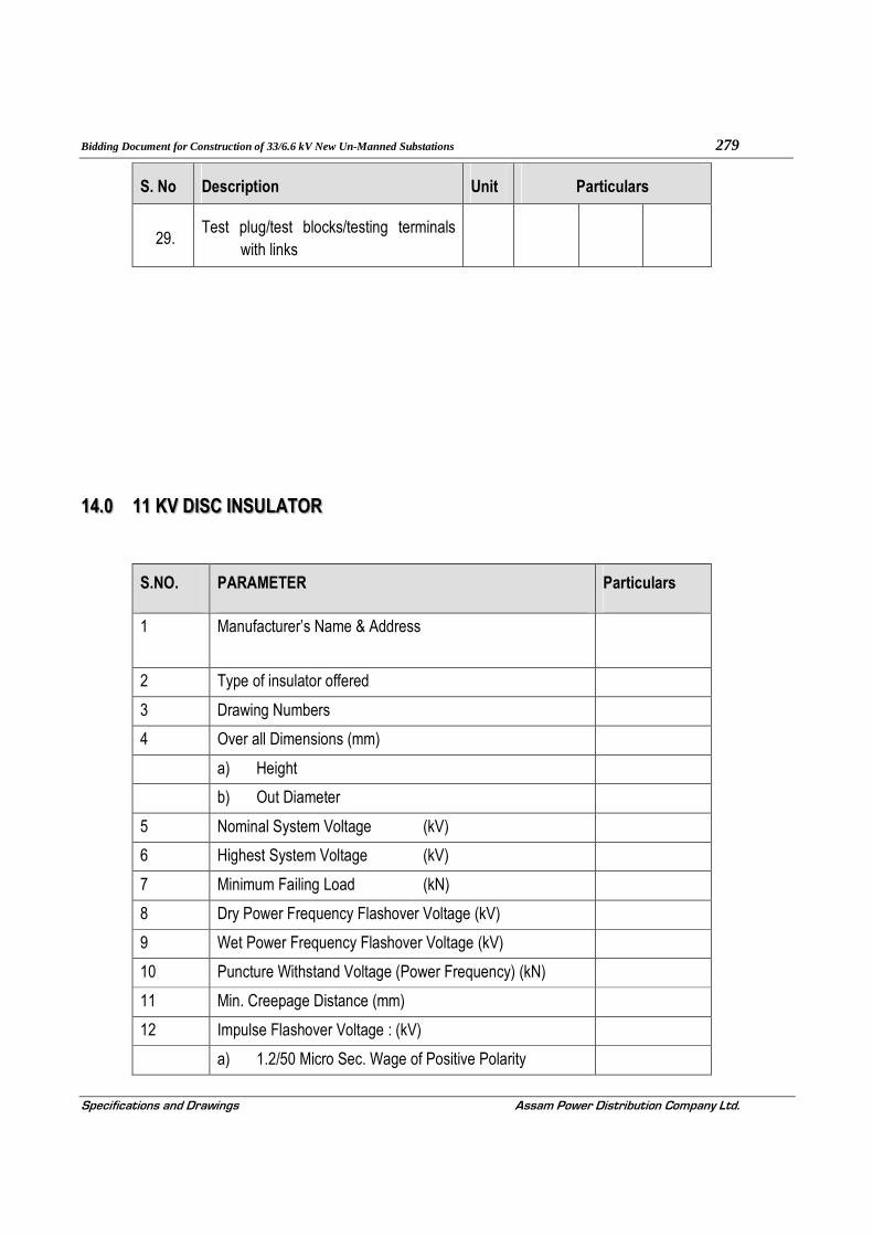
Bidding Document for Construction of 33/6.6 kV New Un-Manned Substations 279
Specifications and Drawings Assam Power Distribution Company Ltd.
S. No Description Unit Particulars
29. Test plug/test blocks/testing terminals
with links
14.0 11 KV DISC INSULATOR
S.NO. PARAMETER Particulars
1 Manufacturer’s Name & Address
2 Type of insulator offered
3 Drawing Numbers
4 Over all Dimensions (mm)
a) Height
b) Out Diameter
5 Nominal System Voltage (kV)
6 Highest System Voltage (kV)
7 Minimum Failing Load (kN)
8 Dry Power Frequency Flashover Voltage (kV)
9 Wet Power Frequency Flashover Voltage (kV)
10 Puncture Withstand Voltage (Power Frequency) (kN)
11 Min. Creepage Distance (mm)
12 Impulse Flashover Voltage : (kV)
a) 1.2/50 Micro Sec. Wage of Positive Polarity

Bidding Document for Construction of 33/6.6 kV New Un-Manned Substations 280
Specifications and Drawings Assam Power Distribution Company Ltd.
S.NO. PARAMETER Particulars
b) 1.2/50 Micro Sec. Wage of Negative Polarity
13 Impulse Withstand Voltage : (kV)
a) 1.2/50 Micro Sec. Wave of Positive Polarity
b) 1.2/50 Micro Sec. Wave of Negative Polarity
14 Dry Power Frequency 1 Min. Withstand Voltage (kN)
15 Wet Power Frequency 1 Min. Withstand Voltage (kN)
16 Minimum Visible Discharge Test Voltage
17 Net Weight (Approx.) (Kg)
18 Standard According to which Porcelain Insulators be Manufactured and Tested
19 Tolerance in Dimensions, if any (as per ISS)
20 Temperature Cycle Test (as per ISS)
21 Porosity Test (as per ISS)
15.0 GALVANIZED STEEL EARTHWIRE
S.NO. Description Unit Parameters
1 Raw Materials
Steel Wires / Rod 9Chemical composition) %
a) Carbon % b) Manganese %
c) Phosphorous %
d) Sulphur %
e) Silicon %
2 Zinc
a) Minimum purity of zinc %
3 Steel Strands After Stranding
3.1 Diameter Mm
i) Nominal
ii) Minimum

Bidding Document for Construction of 33/6.6 kV New Un-Manned Substations 281
Specifications and Drawings Assam Power Distribution Company Ltd.
S.NO. Description Unit Parameters
iii) Maximum
3.2 Maximum breaking load of strand KN
4 Galvanizing
i) Minimum weight of zinc coating per sqm.
Gm
ii) Minimum number of one minute dips that
Nos.
iii) Min. no. of twists in a guage length equal to
Nos.
5 Stranded Earthwire
5.1 No. of strand Steel Outer
5.2 Stranding & wire diameter
5.3 UTS of earthwire KN
5.4 Lay length of outer steel layer Mm
5.5 DC resistance of earthwire at 20 deg.C ohms / km
5.6 Standard length of earthwire M
5.7 Tolerance on standard length ± m
5.8 Direction of lay of outer layer
5.9 Linear mass of earth wire
a) Standard kg/km
b) Minimum kg/km
c) Maximum kg/km
16.0 33 kV POST INSULATOR
S.NO. Description Unit Parameters
1.1.0 Particular of Post Insulator Unit
1.1.1 Make
1.1.2 Type
1.1.3 Size

Bidding Document for Construction of 33/6.6 kV New Un-Manned Substations 282
Specifications and Drawings Assam Power Distribution Company Ltd.
S.NO. Description Unit Parameters
1.1.4 Strength
a) Tensile
b) Torsion
c) Bending (upright)
d) Bending (under hung)
1.1.5 Creepage distance
a) Total
b) Protected
1.1.6 P. F. Flashover voltage
1.1.7 Impulse flashover voltage
1.1.8 One minute P. F. withstand voltage
1.1.9 Impulse Withstand voltage
1.1.10 Dry arcing distance
1.1.11 Weight
17.0 ACSR CONDUCTOR
S.NO. Description Unit Particulars
1.0 Maker’s Name, Address
2.0 Particulars of Raw Materials
2.1 Aluminium
a) Minimum Purity of aluminum %

Bidding Document for Construction of 33/6.6 kV New Un-Manned Substations 283
Specifications and Drawings Assam Power Distribution Company Ltd.
S.NO. Description Unit Particulars
b) Maximum Copper Content %
2.2 Steel Wires/Rods
a) Carbon %
b) Manganese %
c) Phosphorus %
d) Sulphur %
e) Silicon %
2.3 Zinc
a) Minimum Purity of Zinc %
3.0 Aluminum Strands after stranding
3.1 Diameter
a) Nominal mm
b) Maximum mm
c) Minimum mm
3.2 Minimum Breaking Load of Strand kN
3.3 Maximum Resistance of 1m length of Ohm
4.0 Steel Strands after stranding
4.1 Diameter
a) Nominal mm
b) Maximum mm
c) Minimum mm
5.0 Galvanizing

Bidding Document for Construction of 33/6.6 kV New Un-Manned Substations 284
Specifications and Drawings Assam Power Distribution Company Ltd.
S.NO. Description Unit Particulars
a) Minimum weight of zinc coating per
Uncoated wire surface
gm/m2
b) Minimum number of one minute dips galvanized strand can withstand in the preece test
Nos.
c) Minimum number of twists in a guage length times dia of wire which the strand can in the torsion test (after stranding)
Nos.
6.0 ACSR Stranded Conductor
6.1 UTS of Conductor kN
6.2 Lay ratio of Conductor Max.
a) Outer Steel Layer
b) 12 wire aluminum layer
c) 18 wire aluminum layer
d) 24 wire aluminum layer
6.3 D.C. resistance of conductor at 20oC Ohm/Km
6.4 Standard length of conductor M
6.5 Maximum length of conductor that can be Meter
6.6 Tolerance on standard length of conductor %
7.0 Direction of lay for outside layer
7.1 Linear mass of the Conductor
a) Standard Kg/Km
b) Minimum Kg/Km
c) Maximum KgKm
8.0 No. of Cold pressure butt welding available at works Nos.

Bidding Document for Construction of 33/6.6 kV New Un-Manned Substations 285
Specifications and Drawings Assam Power Distribution Company Ltd.
18.0 33KV &11 kV CVT
S. No Description Unit Particulars
1.0 Manufacturer’s name and Address
2.0 Service Outdoor/Indoor
3.0 Rated Capacitance
4.0 Rated Voltage of CVT kV
5.0 Rated Frequency Hz
6.0 Power frequency withstand voltage kV (rms)
7.0 Impulse withstand voltage kV (peak)
8.0 Maximum loss factor at power frequency and rated voltage
9.0 Number of secondary winding
10.0 Rated secondary voltages of each winding
11.0 VA burden of each winding
12.0 Accuracy class of each winding
13.0 Details of mounting arrangement
14.0 Any other information
15.0 Performance guarantee

Bidding Document for Construction of 33/6.6 kV New Un-Manned Substations 286
Specifications and Drawings Assam Power Distribution Company Ltd.
19.0 33KV & 11 KV XLPE CABLE
(This Schedule shall be filled in for each size & category of Cable)
Sl No Description 11 KV 33 KV
1.0 Manufacturer name & address
2.0 Voltage Grade
3.0 Core & Cross section
4.0 Type & Designation (as per ISS)
5.0 List of Standards applicable
6.0 Suitable for system with
a) Service Voltage
b) Neutral Earthing
7.0 Maximum Conductor temperature
a) Continuous (in Deg. C)
b) Short time (in Deg.C)
8.0 Conductor
a) Material to IS-8130(Class/Grade)
b) Size (Sq.mm.)
c) No./Nominal diameter of wires in each conductor (No./mm.)
d) Form of Conductor (Circular/Shaped)
9.0 Shielding/screening on Conductor
a) Material
b) Type
c) Whether thermosetting

Bidding Document for Construction of 33/6.6 kV New Un-Manned Substations 287
Specifications and Drawings Assam Power Distribution Company Ltd.
Sl No Description 11 KV 33 KV
10.0 Insulator
a) Material
b) Thickness(mm.)
c) Whether triple co-extrusion with radiant curing process
11.0 Shielding/screening on insulation
a) Material
b) Type
c) Thickness (mm.)
i. Non-metallic
ii. Metallic
12.0 Inner-sheath
a) Material
b) Type
c) Thickness (mm).
d) Extruded/Wrapped
e) Approx. Outside diameter over sheath (mm.)
13.0 Armouring
a) Material
b) Size
c) D.C. resistance at 20 oC(Ohm/Km.)
d) A.C. resistance at 20 oC
14.0 Inner-sheath

Bidding Document for Construction of 33/6.6 kV New Un-Manned Substations 288
Specifications and Drawings Assam Power Distribution Company Ltd.
Sl No Description 11 KV 33 KV
a) Material
b) Type.
c) Thickness (mm)
15.0 Approx. Overall dia. of the Cable (mm.)
16.0 Standard Drum length with tolerance (Mtr.)
17.0 Net Weight of Cable (approx.) Kg/Km
18.0 Continuous current rating for standard condition, laid direct
a) In ground at temp. 30 oC
b) In duct at temp. oC
c) In air at temp. 40 oC
19.0 Charging current at rated system voltage
20.0 Short Circuit Current at rated system voltage
a) for 1.0 sec
b) for 0.5 sec
21.0 Electrical Parameters
a) Maxm. D.C. resistance/Km of
conductor at 20 oC
b) AC resistance/kilometer (approx.)
c) Reactance/kilometer (approx.)
d) Capacitance/Kilometer(approx.)
e) Di-electric losses at rated(Uo/U) system KV, 50 cycles/sec, in watts/KV/Phase)

Bidding Document for Construction of 33/6.6 kV New Un-Manned Substations 289
Specifications and Drawings Assam Power Distribution Company Ltd.
Sl No Description 11 KV 33 KV
f) (i) Tan-delta at 0.5 Uo
(ii)Tan-Delta at Uo
(iii) Tan-Delta at 1.5 Uo
(iv) Tan-Delta at 2 Uo
22.0 Vol. Resistively at 27 oC (Ohm/Cm)
23.0 Recommended minimum bending radius
24.0 Derating factor for following ambient temperature in Air/Ground
a) at 30 oC
b) at 35 oC
c) at 45 oC
d) at 45 oC
25.0 Type test results of the similar Cable to be furnished with Tender as specified under Clause-12.7.0 of the Spec
a) Tests on Conductor
i. Tensile test (for aluminum)
ii. Wrapping test (for aluminum)
iii. Resistance test
b) Test for armoring wires/strips
c) Test for thickness of insulation & sheath
i. Tensile strength & elongation at break
ii. Ageing in air oven
iii. Hot test

Bidding Document for Construction of 33/6.6 kV New Un-Manned Substations 290
Specifications and Drawings Assam Power Distribution Company Ltd.
Sl No Description 11 KV 33 KV
iv. Shrinkage test
v. Water absorption (Gravimetric)
d) Physical
i. Tensile strength & elongation at break
ii. Ageing in air oven
iii. Shrinkage test
iv. Hot deformation
v. Loss of mass in air oven
vi. Heat shock
vii. Thermal stability
e) Partial discharge test
f) Banding test
g) Di-electric power factor test
i. As a function of Voltage
ii. As a function of temperature
h) Insulation Resistance (Volume receptivity)* Test
i. Heating Cycle test
ii. Impulse with stand test
i) High Voltage test
j) Flammability test
26.0 Cable Drums
a) Length/Drum (Kg)
b) Dimension of Drum (Kg)

Bidding Document for Construction of 33/6.6 kV New Un-Manned Substations 291
Specifications and Drawings Assam Power Distribution Company Ltd.
Sl No Description 11 KV 33 KV
c) Shipping weight (Kg)
27.0 Safe pulling force (Kg.)
28.0 Partial discharge value
29.0 Details of the protective measures against attach by white ante. varnish etc. to be X.L.P.E's outer sheath during manufacture
30.0 Type of curing of XLPE insulation
31.0 Cut ends of the Cable shall be sealed with
32.0 Cable identification shall b made as per clause 12.5.9 (Yes/No)
33.0 Cable Drums shall be marked with the information of Clause 12.6.1 conspicuously (Yes/No)
Note : The tenderes should clearly note that above guaranteed technical particulars are to be given only in the proforma given above and not in random form. Technical particulars given in any other
form shall not be considered. Any extra information can be given separately in the form of annexure
to above technical particulars.

Bidding Document for Construction of 33/6.6 kV New Un-Manned Substations 292
Specifications and Drawings Assam Power Distribution Company Ltd.
20.0 GALVANISED STEEL TUBULAR POLE
Sl No Manufacturer name & address Data
1.0 Type of Pole offered
2.0 a) Whether tubes are of seamless construction. Or welded type.
b) Is it manually welded tubes? If so,state name/address of manufacturer
c) It is ERW tubes? If so, state
3.0 Overall length
4.0 Effective length of section
a) Bottom
b) Middle
c) Top
5.0 Effective dia thickness of section
a) Bottom
b) Middle
c) Top
6.0 Approximate weight (Kg.)
7.0 Breaking Load (Kg.)
8.0 Working Load (Kg.)
9.0 Weight/Mtr.
a) Top Section (kg)

Bidding Document for Construction of 33/6.6 kV New Un-Manned Substations 293
Specifications and Drawings Assam Power Distribution Company Ltd.
Sl No Manufacturer name & address Data
b) Middle Section (kg)
c) Bottom Section (kg)
10.0 Crippling load (kg)
11.0 Load for permanent set
12.0 Load for temporary deflection
13.0 Joint length

Bidding Document for Construction of 33/6.6 kV New Un-Manned Substations 294
Specifications and Drawings Assam Power Distribution Company Ltd
21.0 DISTRIBUTION TRANSFORMER
(To be filled in by Bidder and shall be furnished with the Technical Bid)
Sl. No Description
1. Name of the Manufacturer
2. Installation [indoor/outdoor]
3. Reference standards
4. Continuous Ratings
a) Type of cooling
b) Rating [KVA]
c Rated voltage
i HV [KV rms.]
ii LV [KV-rms.]
d Highest system voltage
i HV [KV rms.]
ii LV [KV-rms.]
e Rated frequency with ±% variation
f Number of phases
g Current at rated full load and on principal tap
i HV [Amps]
ii LV [Amps]
5. Connections
HV
LV
6. Connection symbol and vector group
7. Temperature rise
a Top oil temperature rise

Bidding Document for Construction of 33/6.6 kV New Un-Manned Substations 295
Specifications and Drawings Assam Power Distribution Company Ltd
Sl. No Description
b Winding Temperature rise
c Temperature gradients between windings & oil.
d Limit of Hot spot temperature for which the Transformer is designed [°C]
8. Type of OFF load tap changing switch
9. Tapping on windings for
i Constant flux/variable flux/combined
Regulation
ii Tapping provided at
iii Number of steps
iv Range of tapping for variation [+ percent to - percent]
10. i No load loss at rated voltage and frequency at principal tap [KW]
ii No load loss at the voltage corresponding to highest tap [KW]
11. Load loss at rated output, rated frequency, corrected for 75 °C winding temperature at:- [Copper loss]
i Normal tap [In KW]
ii Highest tap [In KW]
iii Lowest tap [In KW]
12. Total losses at normal ratio
13. Positive sequence impedance on rated KVA base at rated current and frequency at 75°Centigrade winding temperature at
i Normal tap [%]
ii Highest tap [%]
iii Lowest tap [%]

Bidding Document for Construction of 33/6.6 kV New Un-Manned Substations 296
Specifications and Drawings Assam Power Distribution Company Ltd
Sl. No Description
14. % reactance at rated KVA base at rated
current and rated frequency at
i Normal tap [%]
ii Highest tap [%]
iii Lowest tap [%]
15. % resistance at rated KVA base at rated current and rated frequency at
i Normal tap [%]
ii Highest tap [%]
iii Lowest tap [%]
16. % Impedance at rated KVA base at rated current and rated frequency at
i Normal tap [%]
ii Highest tap [%]
iii Lowest tap [%]
17. a Polarisation index i.e. ratio of Megger values at 600 secs to 60 secs, (H.V. to E, L.V. to E, & H.V.to L.V.). Measurement by 2.5 kV motorised megger.
In Between PI
H.V - E
L.V. - E
H.V – L.V.
b Insulation Resistance in MΩ
(At temp ……….0C)
HV – E :
LV – E :
HV – LV :
c Regulation at full load and 75°C winding temperature expressed as a percentage of normal voltage
i At unity power factor [%]
ii At 0.8 power factor [lagging][%]

Bidding Document for Construction of 33/6.6 kV New Un-Manned Substations 297
Specifications and Drawings Assam Power Distribution Company Ltd
Sl. No Description
18. Efficiency at 75°C winding temperature as derived from guaranteed loss figures and at
Unity power
factor
0.8 Power
factor
a At full load [%]
b At ¾ load [%]
c At ½ load [%]
19. i Maximum efficiency [%]
ii Load at which maximum efficiency occurs[% of full load]
20. Short time thermal rating of
i HV winding in KA and duration in seconds
ii LV winding in KA and duration in seconds
21. Permissible over loading:-
a HV winding
b LV winding
22. Terminal arrangement
a High voltage [HV]
b Low voltage (LV)
c Neutral
23. Rating & Type of inbuilt HV side fuse
Make of fuse
24. a Rating & Type of ACB/MCCB
b Make of ACB/MCCB
25. a Thickness of Terminal Enclosure
b IP protection of enclosure
26. Insulating and cooling medium

Bidding Document for Construction of 33/6.6 kV New Un-Manned Substations 298
Specifications and Drawings Assam Power Distribution Company Ltd
Sl. No Description
27. Test voltage HV LV
i Lightning impulse withstand test voltage [KVP]
ii Power frequency withstand test voltage [dry and wet][for 1 minute] [KV-rms.]
28. External short circuit withstand capacity [MVA] and duration [seconds]
29. Over-fluxing withstand capability of the
Transformer
30. DETAILS OF CORE
a Type of core construction
b Type of corner joints of the core
c Maximum flux density at
i Rated voltage [11/0.4 KV] & rated frequency 50 Hz][in Tesla]
ii Highest system voltage [12/1.1 KV] and lowest system frequency [48.5Hz.][in Tesla]
d No load current, no load loss and no load power factor at normal ratio and frequency [Amp/KW/p.f.]
No load current
No Load Loss
No Load PF
i 10 percent of rated voltage
ii 25 percent of rated voltage
iii 50 percent of rated voltage
iv 85 percent of rated voltage
v 100 percent of rated voltage
vi 105 percent of rated voltage
vii 110 percent of rated voltage
viii 112.5 percent of rated voltage
ix 115 percent of rated voltage

Bidding Document for Construction of 33/6.6 kV New Un-Manned Substations 299
Specifications and Drawings Assam Power Distribution Company Ltd
Sl. No Description
x 120 percent of rated voltage
xi 121 percent of rated voltage
xii 125 percent of rated voltage
e Core laminations:-
i Material of core lamination [M4/HIB]
ii Grade of core laminations
iii Thickness of core lamination [mm]
iv Specific loss [watt/Kg.] at rated voltage and rated frequency
v Specific loss [watt/Kg.] at highest system voltage and lowest system frequency
vi Whether specific core loss graph [flux density vs. watt/Kg. submitted
vii VA/Kg at rated voltage and rated frequency
viii VA/Kg. at highest system voltage and lowest system frequency
ix Whether VA/Kg. Vs. flux density graph Submitted
x Insulation of core laminations
f CORE ASSEMBLY:-
i Core diameter [mm]
ii Core window height [mm]
iii Core leg centre [mm]
iv Gross core cross-sectional area [cm²]
v Whether details of core widths, stacks and calculation furnished as per enclosed annexure
vi Distance between centers [mm]
vii Total height of core [mm]
viii 1) Details of core Clamping with nos. of

Bidding Document for Construction of 33/6.6 kV New Un-Manned Substations 300
Specifications and Drawings Assam Power Distribution Company Ltd
Sl. No Description
core stud.
2) Material, grade & type
3) Width
4) Thickness
5) Fixing method
ix Details of top end frame
x Details of Bottom end frame
xi Details of clamp plate [Material, thickness, Insulation]
xii Total core weight [kg]
xiii Core loss basing on core loss graph at operating flux density [rated voltage and rated frequency] [kw]
xiv Core stacking factor
xv Net core area Sq. cm.
g Describe location/method of core grounding
h Details of oil ducts in core if any
i Peak value of magnetizing Inrush current (% of HV rated current).
31. DETAILS OF WINDINGS. HV LV
a Type of winding
b Material of the winding conductor
c Maximum current density of windings [at rated current] and conductor area
Conductor area [cm²]
Current density
[A/cm²]
i HV
ii L.V.
e Whether windings are pre-shrunk?

Bidding Document for Construction of 33/6.6 kV New Un-Manned Substations 301
Specifications and Drawings Assam Power Distribution Company Ltd
Sl. No Description
f Whether adjustable coil clamps are provided for H.V. and L.V. windings?
g Whether steel rings or perma wood are used for the windings? If steel rings used, whether these are split?
h Winding Insulation. Type & class
i H.V.
ii LV Winding
i Insulating material used for
i H.V.
ii L.V Winding
iii Tapping connection
j Insulating material used between
i H.V. and L.V. winding
ii Core and L.V winding
iii H.V. winding and core
iv H.V. to H.V. winding [between phases]
V Inter coil spacers between HV sections (mm)
Vi Type of block between HV sections
Vii Oil duct between LV to cylinder (mm) :
Cylinder to HV (mm) :
k Type of axial coil supports
i H.V. winding
ii LV winding
l Type of radial coil supports
i H.V. winding
ii LV winding

Bidding Document for Construction of 33/6.6 kV New Un-Manned Substations 302
Specifications and Drawings Assam Power Distribution Company Ltd
Sl. No Description
m Maximum allowable torque on coil clamping HV & LV bolts
n Bare conductor size (mm). HV :
LV :
o Insulated conductor size (mm). HV :
LV :
p Number of coil per phase HV :
LV :
q No. of conductors in parallel (Nos.). HV :
LV :
r No. of turns/phase HV coil :
LV coil :
s Inside diameter (mm). HV coil :
LV coil :
t Outside diameter (mm). HV coil :
LV coil :
u Axial height after shrinkage (mm). HV coil :
LV coil :
v D.C.RESISTANCE
i L.V winding at 75 ° C (Ohms).
ii HV winding at normal tap at 75° C (Ohms).
iii HV winding and at highest tap at 75° C (Ohms).
iv HV winding at lowest tap. (Ohms).
v Total I²R losses at 75 ° C. for normal tap. (KW).
vi Total I²R losses at 75 ° C. for highest tap. (KW)
vii Total I²R losses at 75 ° C for lowest tap.(KW).

Bidding Document for Construction of 33/6.6 kV New Un-Manned Substations 303
Specifications and Drawings Assam Power Distribution Company Ltd
Sl. No Description
viii Stray losses including eddy current losses in winding at 75°C (KW).
a Normal tap position
b Highest tap position
c Lowest tap position.
d Any special measures taken to reduce eddy current losses and stray losses, mention in details
w Load losses at 75°C [I²R + stray].
a Normal tap position [KW].
b Highest tap position [KW].
c Lowest tap position [KW].
w Details of special arrangement provided to improve surge voltage distribution in the windings
32. BUSHINGS. HV LV Neutr
al
a Make and type
i Rated voltage class [KV-rms.]
ii Rated current [Amps.]
b Lightning Impulse withstand test voltage [1.2/50 micro second][KVP]
c Power frequency withstand test voltage
i Wet for 1 minute [KV-rms]
ii Dry for 1 minute [KV-rms]
d Minimum creepage distance in mm
e Weight of assembled bushing [Kg.]
f Minimum clearance height for removal of bushing [mm]

Bidding Document for Construction of 33/6.6 kV New Un-Manned Substations 304
Specifications and Drawings Assam Power Distribution Company Ltd
Sl. No Description
g Under oil flashover or puncture impulse voltage [KVP]
h Under oil flashover or puncture power frequency voltage (KV-rms).
i Phase to earth clearance in air of live parts at the top of bushings
33. Minimum clearance [mm] In Oil Out of Oil
Between
windings
Phase
to
Ground
Between
windings
Phase
to
Ground
HV
LV
a Radial clearance between LV and HV (mm)
b Radial clearance between core to LV (mm)
c End clearance of HV coil to yoke (mm)
d End clearance of LV coil to yoke (mm)
e Gap between yoke to bottom of tank (mm)
34. Weight [Tolerance + 5%]
[Approximate value is not allowed]
a Core [Kg.]
b Core with clamping [Kg.]
c H.V. winding insulated conductor [Kg.]
d L.V.winding insulated conductor [Kg.]
e Coils with insulation [Kg.]
f Core and winding [Kg]
g Oil required for first filling [Liter/Kg.]
h Tank and fittings with accessories [Kg.]

Bidding Document for Construction of 33/6.6 kV New Un-Manned Substations 305
Specifications and Drawings Assam Power Distribution Company Ltd
Sl. No Description
i Untanking weight [Kg.]
j Total weight with oil and fittings [kg.]
35. DETAILS OF TANK
a Material for Transformer tank
b Type of tank
c Thickness of sheet
[No approximate value to be mentioned]
i Sides [mm]
ii Bottom [mm]
iii Cover [mm]
iv Radiators [mm]
d Inside dimensions of main tank
[No approximation in dimensions to be used]
i Length [mm]
ii Breadth [mm]
iii Height [mm]
e Outside dimensions of main tank
[No approximation in dimensions to be used]
i Length [mm]
ii Breadth [mm]
iii Height [mm]
f Thickness of spray galvanisation of tank bottom.
g Vacuum recommended for hot oil circulation [torr]
h Vacuum to be maintained during oil filling in Transformer tank [torr]
i Vacuum to which the tank can be subjected without distortion [torr]

Bidding Document for Construction of 33/6.6 kV New Un-Manned Substations 306
Specifications and Drawings Assam Power Distribution Company Ltd
Sl. No Description
j No. of bi-directional wheels provided
k Track gauge required for the wheels
i Transverse axis
ii Longitudinal axis
l Type and make of pressure relief device and minimum pressure at which it operates [Kpa]
36. CONSERVATOR
a Total volume [Liters]
b Volume between the highest and lowest visible oil levels [Litres]
37. OIL QUALITY
a Governing standard
b Density in gms/cu-cm
c Kinematics viscosity in CST
d Inter facial tension at 27°C in N/m
e Flash point in °C
f Pour point in °C
g Acidity [neutralization value] in mg of KOH/gm
h Corrosive sulfur in %
i Electric strength [breakdown voltage]
i As received [KV-rms.]
ii After treatment [KV-rms.]
j Dielectric dissipation factor [tan delta] at 90°C
k Saponification value in mg of KOH/gm
l Water content in ppm

Bidding Document for Construction of 33/6.6 kV New Un-Manned Substations 307
Specifications and Drawings Assam Power Distribution Company Ltd
Sl. No Description
m Specific resistance
i At 90°C [ohm-cm]
ii At 27 °C [ohm-cm]
o Oxidation stability
i Neutralization value after oxidation
ii Total sludge after oxidation
p Characteristic of oil after ageing test as per ASTMD-1934
i Specific resistance at
27°C [ohm-cms]
90°C [ohm-cms]
ii Tan delta
iii Sludge content
iv Neutralization number
v Details of oil preserving equipment offered
38. RADIATORS
a Overall dimensions lxbxh [mm]
b Total weight with oil [Kg.]
c Total weight without oil [Kg.]
d Thickness of radiator tube [mm]
e Types of mounting
f Vacuum withstand capability
g Total radiating surface in sq.m
h Type and make of material used for the radiators
i Total number of radiators/Banks for
Transformer and dimensions of tubes

Bidding Document for Construction of 33/6.6 kV New Un-Manned Substations 308
Specifications and Drawings Assam Power Distribution Company Ltd
Sl. No Description
j Thickness of hot dip galvanization of radiators
39. TEMPERATURE INDICATORS
a Make and type
b Scale
c Size [lxbxd]
d Nos.
40. APPROXIMATE OVERALL DIMENSIONS
OF TRANSFORMER
Length [mm]
Breadth [mm]
Height [mm]
41.
a Minimum clearance height for lifting core and winding from tank [mm]
b Minimum clearance height for lifting tank cover [mm]
42. SHIPPING DETAILS
a Approximate weight of heaviest package [Kg.]
b Approximate dimensions of largest Package [Kg.]
43. Transformers will be transported with oil.
44. TAP CHANGING EQUIPMENT
[These details refer to the basic rating of T.C. as guaranteed by TC manufacturers]
a Make
b Type
c Rated voltage to earth [KV]
d Rated current [Amps.]

Bidding Document for Construction of 33/6.6 kV New Un-Manned Substations 309
Specifications and Drawings Assam Power Distribution Company Ltd
Sl. No Description
e Step voltage [volts]
f Number of steps
g Approximate overall dimensions of tap changer [WxBxD] in mm
h Approximate overall weight [Kg.]
45. Types of terminal connectors and drawing No
a HV
b LV
46. Details of painting, galvanization conforms to this Specification [Yes/No]
47. No. of breathers provided [Nos.]
48. Type of dehydrating agent and quantity used for breathers
49. Valve sizes and numbers
a Filter valves- mm-Nos
b Sampling valves- mm-Nos
Sludge removal valve
Oil drain valve
50. a Type and make of PRV
b No. of each type of devices per transformer
c Min. pressure at which device operates
Make of Buchholz relay
Pair of NO contacts
51. Make of MOLG
Dimensions
52. Make of OTI & WTI
Type and Size of OTI/WTI

Bidding Document for Construction of 33/6.6 kV New Un-Manned Substations 310
Specifications and Drawings Assam Power Distribution Company Ltd
Sl. No Description
53. Please enclose the list of accessories and fittings, being provided on transformer. Please confirm, these are as stipulated in the tender
54. Whether the transformer, covered is fully type tested and if so, whether copies of type test certificates, enclosed with the tender
55. Please confirm that you will guarantee maximum Impedance variation between phases within the limit of 2% only
56. a Please confirm that the transformer shall be dried by vapour/ vacuum-phase drying method. Please specify level of dryness

Bidding Document for Construction of 33/6.6 kV New Un-Manned Substations 311
Specifications and Drawings Assam Power Distribution Company Ltd
SECTION-18
DRAWINGS

Bidding Document for Construction of 33/6.6 kV New Un-Manned Substations 312
Specifications and Drawings Assam Power Distribution Company Ltd
A
B
B
A
B
ROAD (3.75M W
IDE)
TR−1
TR−2
TR−3
TR−4
CAP−1
MTR
CAP−2
BC
BAT
ACDB
DB
1 2 3 4 5 6
1 2 3 4 5 6
A
B
C
D
A
B
C
D
A
B
C
DLAYOUT PLAN, SADILAPUR WSS
GMDA/ SADILAPUR/001
GMDA WATER SUPPLY
SCHEME
NOTES:-
FOR 33kV
FOR 6.6kV
SECTION-BBVIEW - AA
33kV FEEDER33kV FEEDER

Bidding Document for Construction of 33/6.6 kV New Un-Manned Substations 313
Specifications and Drawings Assam Power Distribution Company Ltd
SECTION-BBVIEW - AA
33kV FEEDER33kV FEEDER
A
B
B
A
B
ROAD (3.75M W
IDE)
TR−1
TR−2
TR−3
TR−4
CAP−1
MTR
CAP−2
BC
BAT
ACDB
DB
1 2 3 4 5 6
1 2 3 4 5 6
A
B
C
D
A
B
C
D
A
B
C
DLAYOUT PLAN, PANDU GHAT WSS
GMDA/ PANDUGHAT/001
GMDA WATER SUPPLY
SCHEME
NOTES:-
FOR 33kV
FOR 6.6kV

Bidding Document for Construction of 33/6.6 kV New Un-Manned Substations 314
Specifications and Drawings Assam Power Distribution Company Ltd
1 2 3
1 2 3
A
B
C
D
A
B
C
D
T0 MCC
6.3 MVA
33/6.6 kV
6.3 MVA
33/6.6 kV
1.6 MVA
33/0.433 kV
1.6 MVA
33/0.433 kV
CableCable
T0 MCC
SINGLE LINE DIAGRAM, SADILAPUR WSS
GMDA/ SADILAPUR/002
GMDA WATER SUPPLY
SCHEME
CAPACITOR
BANK
CAPACITOR
BANK
33 KV LINE 33 KV LINE
Cable CableCableCable

Bidding Document for Construction of 33/6.6 kV New Un-Manned Substations 315
Specifications and Drawings Assam Power Distribution Company Ltd
1 2 3
1 2 3
A
B
C
D
A
B
C
D
T0 MCC
1.6 MVA
33/6.6 kV
1.6 MVA
33/6.6 kV
250 KVA
33/0.433 kV
250 KVA
33/0.433 kV
CableCable
T0 MCC
SINGLE LINE DIAGRAM, PANDU GHAT WSS
GMDA/ PANDUGHAT/002
GMDA WATER SUPPLY
SCHEME
CAPACITOR
BANK
CAPACITOR
BANK
Cable Cable
33 KV LINE 33 KV LINE
CableCable