Specialist engineering assessment
45
Procedure Doc no. D0001870 Document uncontrolled when printed Page: 1 of 45 Version: 1 Issue date: 19/02/2021 Specialist Engineering Assessment 1. General ............................................................................................................................. 5 1.1 Introduction....................................................................................................................................... 5 1.2 Scope ................................................................................................................................................. 5 1.3 Building Works Covered by the SEA.............................................................................................. 6 2. Engineering Assurance of SEA Submissions ............................................................... 8 2.1 Personnel Competency.................................................................................................................... 8 2.2 Verification and Independent Verification ..................................................................................... 8 3. Understanding Risks to Sydney Water assets .............................................................. 9 4. Specialist Engineering Assessment Process.............................................................. 11 4.1 Overview .......................................................................................................................................... 11 4.2 Gather Background information ................................................................................................... 11 4.3 Electrical Considerations .............................................................................................................. 15 4.4 Geotechnical and Structural Appraisals ...................................................................................... 16 4.5 Structural Appraisal of Predicted Impacts .................................................................................. 22 4.6 Threshold Impact Criteria .............................................................................................................. 27 4.7 Vibration Limits .............................................................................................................................. 28 4.8 Asset protection measures ........................................................................................................... 29 4.9 Instrumentation and Monitoring plan ........................................................................................... 30 4.10 Work Method Statement ................................................................................................................ 32 4.11 Contingency plan ........................................................................................................................... 32 4.12 Specialist Engineering Assessment Report Contents ............................................................... 33 5. References ..................................................................................................................... 35 6. Ownership ...................................................................................................................... 37 6.1 Ownership ....................................................................................................................................... 37 6.2 Change history ............................................................................................................................... 37 7. Appendices .................................................................................................................... 37 Appendix A: SEA Process flowchart ......................................................................................... 38 Appendix B: SEA Submission Checklist ................................................................................... 40 Appendix C: Table of Contents Required in the SEA Report .................................................. 45
Transcript of Specialist engineering assessment

Procedure
Doc no. D0001870 Document uncontrolled when printed Page: 1 of 45Version: 1 Issue date: 19/02/2021
Specialist Engineering Assessment
1. General ............................................................................................................................. 5
1.1 Introduction ....................................................................................................................................... 5
1.2 Scope ................................................................................................................................................. 5
1.3 Building Works Covered by the SEA .............................................................................................. 6
2. Engineering Assurance of SEA Submissions ............................................................... 8
2.1 Personnel Competency.................................................................................................................... 8
2.2 Verification and Independent Verification ..................................................................................... 8
3. Understanding Risks to Sydney Water assets .............................................................. 9
4. Specialist Engineering Assessment Process .............................................................. 11
4.1 Overview .......................................................................................................................................... 11
4.2 Gather Background information ................................................................................................... 11
4.3 Electrical Considerations .............................................................................................................. 15
4.4 Geotechnical and Structural Appraisals ...................................................................................... 16
4.5 Structural Appraisal of Predicted Impacts .................................................................................. 22
4.6 Threshold Impact Criteria .............................................................................................................. 27
4.7 Vibration Limits .............................................................................................................................. 28
4.8 Asset protection measures ........................................................................................................... 29
4.9 Instrumentation and Monitoring plan ........................................................................................... 30
4.10 Work Method Statement ................................................................................................................ 32
4.11 Contingency plan ........................................................................................................................... 32
4.12 Specialist Engineering Assessment Report Contents ............................................................... 33
5. References ..................................................................................................................... 35
6. Ownership ...................................................................................................................... 37
6.1 Ownership ....................................................................................................................................... 37
6.2 Change history ............................................................................................................................... 37
7. Appendices .................................................................................................................... 37
Appendix A: SEA Process flowchart ......................................................................................... 38
Appendix B: SEA Submission Checklist ................................................................................... 40
Appendix C: Table of Contents Required in the SEA Report .................................................. 45

Specialist Engineering Assessment
Doc no. D0001870 Document uncontrolled when printed Page: 2 of 45Version: 1 Issue date: 19/02/2021
Tables
Table 1: Suggested parameters for infill material around Brick Oviform structures ........................................ 19
Table 2: Suggested upper bound shear capacity and tensile capacity to be adopted for construction joints . 22
Table 3: Suggested upper bound parameters for unreinforced concrete (not at construction joints) ............. 22
Table 4: Threshold Impact Criteria for longitudinal impacts for lower risk pipe assets up to DN600 .............. 27
Table 5: Threshold impact criteria for higher risk assets ................................................................................. 28
Table 6: Threshold Vibration Limits ................................................................................................................. 29
Table 7: Example of contents in instrumentation monitoring points & limits ................................................... 31
Table 8: Contingency plan ............................................................................................................................... 32
Figures
Figure 1: Excessive movement of retaining wall causing road damage and onward failure of water main ...... 9
Figure 2: Typical example of infiltration through cracks in a brick oviform ...................................................... 10
Figure 3: Minimum clearance to building works for direct buried assets (i.e. not in tunnel) ............................ 14
Figure 4: Minimum clearance to building works for assets within tunnels ....................................................... 15
Figure 5: Example cross section of a Brick Oviform ........................................................................................ 19
Figure 6: Typical arrangement of forms for Sydney Water unreinforced concrete asset ................................ 20
Figure 7: Location of construction joints for a typical Sydney Water unreinforced concrete asset ................. 21
Figure 8: Example of a longitudinal crack in a brick oviform conduit ............................................................... 25
Figure 9: Typical unreinforced concrete lined tunnel showing reduced section .............................................. 26

Specialist Engineering Assessment
Doc no. D0001870 Document uncontrolled when printed Page: 3 of 45Version: 1 Issue date: 19/02/2021
Revision details
Version No. Clause Description of revision
1 - Original issue
Foreword
This Procedure relates only to Sydney Water assets.
Sydney Water makes no warranties, express or implied, that compliance with the contents of this Procedure is sufficient to ensure safe systems of work or operation.
It is the user’s sole responsibility to ensure that the copy of the Procedure is the current version as in use by Sydney Water.
Sydney Water accepts no liability whatsoever in relation to the use of this Procedure by any party, and Sydney Water excludes any liability which arises in any manner from the use of this Procedure.
For the purpose of this Procedure “Sydney Water” is the nominated person or organisation that has written authority to act on Sydney Water’s behalf, for the specific works included in this procedure.
This document is uncontrolled once printed or downloaded.
Copyright
The information in this document is protected by Copyright and no part of this document may be reproduced, altered, stored or transmitted by any person without the prior consent of Sydney Water.
Abbreviations and Terms
Abbreviation Definition
BOA Build Over or Adjacent
CGD City Growth and Development Team in Sydney Water
PPV Peak Particle Velocity
SEA Specialist Engineering Assessment
SWC Sydney Water Cooperation
WMS Work Method Statement
ZOI Zone of Influence

Specialist Engineering Assessment
Doc no. D0001870 Document uncontrolled when printed Page: 4 of 45Version: 1 Issue date: 19/02/2021
General Terms & Definitions
Term Definition
Building Works As defined in Section 1.3 of this document
Critical Assets Critical Assets are those structures that are critical to the performance of Sydney Water’s services and whose service disruption due to damage or unscheduled maintenance may have significant impacts on public health, safety, Sydney Water’s reputation, the environment, compliance with regulations, financial, community, customers or network performance.
External Activity Any work proposed in the vicinity of a Sydney Water asset that may have an impact on the Sydney Water asset. This excludes regular maintenance activities carried out by Sydney Water.
The Proponent Party proposing to carry out an external activity in the vicinity of Sydney Water assets.
New Assets Sydney Water assets built within last 5 years prior to the date of SEA
High Risk Assets For the purpose of preparing a SEA, buried pipes, conduits, channels/ culverts (and associated structures such as maintenance holes) with any internal dimension greater than or equal to 750mm, or any civil, mechanical and electrical structures/ equipment associated with treatment plants, pumping stations, dams/ reservoirs, aqueducts and buildings/ facilities must be considered as high risk.
Specialist Engineering Assessment
Doc no. D0001870 Document uncontrolled when printed Page: 5 of 45Version: 1 Issue date: 19/02/2021
General
Introduction Sydney Water manages an extensive network of assets to supply water, recycle water, collect wastewater,
and stormwater services to more than five million people within its areas of operation.
These assets may be subjected to additional stresses and strains due to loads or actions (e.g. ground
movements) from nearby building works. This may result in adverse impacts such as physical damage,
reduced performance, reduced service life and impaired access for operation and maintenance.
The Proponent for building works that could impact on Sydney Water assets must design and construct building works such that there are no adverse impacts to the assets. Where required by this procedure, the Proponent must undertake a Specialist Engineering Assessment (SEA) to demonstrate there will be no adverse impact or nominate protection measures to prevent any adverse impact to Sydney Water assets.
Broadly, a SEA is intended to provide details of the following to Sydney Water:
1. All background information related to the building works, ground conditions and SWC assets that have the potential to be impacted
2. An engineering appraisal to predict and understand impacts to Sydney Water assets
3. Design details of the protective measures to be Implemented, if any, to protect Sydney Water assets
4. A monitoring plan to confirm nominated work methods are being followed and actual impacts during and post the works are within predicted limits
5. A Work Method Statement (WMS) describing construction activities to ensure impacts are within predicted limits
6. A contingency plan describing the required activities in the event of an unexpected incident.
All personnel involved with preparation of a SEA must meet the requirements of “Sydney Water Engineering
Competency Standard”.
Proponents undertaking building works are accountable for rectification of any adverse impacts to Sydney
Water assets and any consequential losses resulting from their works.
This document must be read in conjunction with Sydney Water “Technical Guidelines- Building over and
adjacent to pipe assets” and “Building over or adjacent to our stormwater assets”.
Scope This procedure applies to anyone proposing to carry out building works near Sydney Water assets. This
includes, but is not limited to Sydney Water Construction, Operations and Maintenance staff, Contractors,
Developers, and other agencies or authorities.
This procedure applies to all Sydney Water assets such as pipelines, conduits, channels, culverts and
associated structures (direct buried and in tunnel), and Network and Treatment facilities such a reservoirs,
pumping stations, aqueducts and buildings constructed from a variety of materials including, but not limited
to reinforced concrete, unreinforced concrete (box section with arched roof), masonry (oviform conduits and
arches), clay, plastics, cast iron and mild steel.

Specialist Engineering Assessment
Doc no. D0001870 Document uncontrolled when printed Page: 6 of 45Version: 1 Issue date: 19/02/2021
The procedure only nominates engineering requirements, and does not cover requirements for the following
items:
Building works approval processes
System planning (e.g. future asset augmentation or renewal)
Property instruments (e.g. easements)
Environmental or community impacts
Aspects of the Proponent’s designs including, but not limited to structural adequacy, constructability, interaction with assets, utilities or structures owned by others.
Building Works Covered by the SEA
1.3.1 Building Works
Building works include any external activity that may adversely impact on Sydney Water assets. Where
reference is made to external activities being ‘adjacent’ or ‘nearby’, this means over, under, or next to.
Examples of temporary and permanent external activities that may impact adversely on nearby Sydney
Water assets include, but are not limited to:
New buildings, structures or fixtures
Heavy vehicles, construction plant and equipment
Outrigger loads from construction and delivery vehicles (e.g. cranes).
Excavations
Dewatering
Placement of fill material or construction material stockpiles
Trenchless construction such as boring, pipejacking, micro-tunnelling and horizontal directional drilling
Tunnelling works
Mining works (e.g. subsidence, vibration, blasting)
Piling or ground anchor installation
Ground improvement works such as compaction, dynamic compaction, impact rolling, grouting, jet-grouting and soil nailing
Vibration associated with construction activities, including rock excavation
Construction activities in soft or compressible soils prone to significant settlement and/ or instability such as landslide risk
Sydney Water assets are not designed for impacts caused by adjacent building works such as additional
external loads, imposed ground movements and other actions, and hence may be damaged. The risk of
adverse impacts to Sydney Water assets must be carefully accounted for on a case by case basis and are
influenced by the specific site and ground conditions. Impacts may only be temporary but can cause
permanent damage and increase the risk of long-term deterioration of the asset. Hence temporary impacts
must also be considered in the SEA.

Specialist Engineering Assessment
Doc no. D0001870 Document uncontrolled when printed Page: 7 of 45Version: 1 Issue date: 19/02/2021
1.3.2 Zone of influence
The zone of influence is the area surrounding SW assets that is affected by adjacent building works. This
may be due to external loading, ground movements, dewatering or any other action that can adversely
impact SW assets. Examples of minimum extents of zone of influence (ZOI) are defined in the SW guideline
for Building Over and Adjacent (BOA) to pipe assets. However, the ZOI defined in the BOA guideline is
primarily focussed on imposed external loads, and does not consider ground movements caused by
excavation, tunnelling or dewatering.
The ZOI related to specific building works must be assessed by a competent geotechnical engineer and a
competent civil/ structural engineer as required by the SWC Engineering Competency Standard.
1.3.3 Conditions when a SEA is required
A Specialist Engineering Assessment (SEA) is required when any of the following assets is with within the
building works zone of influence.
Reticulation pipes (of size less than or equal to DN300) that do not meet requirements nominated in the Technical Guidelines- Building over and adjacent to pipe assets
Pipes, conduits, culverts and associated structures with any internal dimension greater than 300mm (i.e. non-reticulation assets)
High-risk assets (refer general terms and definitions)
Critical assets nominated by Sydney Water.

Specialist Engineering Assessment
Doc no. D0001870 Document uncontrolled when printed Page: 8 of 45Version: 1 Issue date: 19/02/2021
Engineering Assurance of SEA Submissions
Personnel Competency All personnel providing input to the SEA must be competent. That is, possess appropriately relevant
qualifications, knowledge, skills and experience to carry out their task successfully.
The complexity and level of detail required for the SEA may be greater than for the design of the external
activities. To analyse the ground/structure interaction necessary for Critical Assets, complex or high-risk
assets, and understanding the risks to Sydney Water assets, requires Geotechnical, Civil and Structural
engineers with appropriate qualifications, in-depth knowledge, high levels of skills and experience. Closely
coordinated analysis and reporting is required between the various engineering disciplines.
Verification and Independent Verification The Sydney Water Engineering Competency Standard sets out minimum requirements for competency of
personnel undertaking various SEA tasks, and requirements for independent verification. The Proponent
must comply with the standard when engaging engineering personnel and with the submissions to Sydney
Water.
The SEA must be prepared in accordance with a quality management system complying with ISO 9001. It
must specifically address all Sydney Water assets at risk from the building works and must cover all aspects
that may be of influence. The documentation should as a minimum include:
Discuss the records of design and development inputs
Provide certification from competent engineers
Discuss, threshold criteria, adopted site specific impact criteria, conformance with impact criteria, and any non-conforming results
Provide condition surveys and appraisal of the existing condition of the assets.
Document corrective or asset protection measures to be undertaken, if required.
Sydney Water may review the submitted SEA and provide comment for consideration. Sydney Water does
not verify the SEA. Sydney Water review of the submitted SEA including any supporting documentation
does not relieve the author(s) of their responsibilities. Responsibility for the SEA remains with the author(s).

Specialist Engineering Assessment
Doc no. D0001870 Document uncontrolled when printed Page: 9 of 45Version: 1 Issue date: 19/02/2021
Understanding Risks to Sydney Water assets Sydney Water is responsible for meeting Public Health, Safety, Environmental, regulatory and performance
requirements, and also community expectations with respect to management of its assets.
Changes to external loads, ground or groundwater conditions or ground stress relaxation may cause
localised or more extensive damage to Sydney Water assets or induce stress changes or deformations that
could impact long-term durability of the asset.
The Proponent must design, and construct works such that the long-term structural integrity of Sydney
Water assets is not compromised.
The Proponents undertaking building works are accountable for rectification of any damage and
consequential losses from damage to Sydney Water assets caused by their works. This applies to
damage occurring during and after construction. The Proponent is also accountable for any further
damage and deterioration of an asset after the works are complete. For example, ongoing movements
or erosion causing widening of cracks in a tunnel lining that develop after damage of the lining occurs during
construction.
Figure 1: Excessive movement of retaining wall causing road damage and onward failure of water main
Failure of an asset is not limited to total collapse. Cracking leading to infiltration/exfiltration may be a
failure resulting in environmental damage or ongoing deterioration of the asset through erosion of backfill.
This may in the long-term result in damage/collapse of the asset or surrounding ground. Ground movement
may cause tilting or sagging of gravity assets and result in hydraulic impairment.

Specialist Engineering Assessment
Doc no. D0001870 Document uncontrolled when printed Page: 10 of 45Version: 1 Issue date: 19/02/2021
Figure 2: Typical example of infiltration through cracks in a brick oviform
Concrete cracking may result in increased corrosion of steel reinforcement or the exposure of concrete
surface to chemical attack. Hence cracking may result in reduced service life. Any change in the condition
of an asset may impair operation and increase maintenance.
Sydney Water assets must always be maintained in a serviceable condition and any potential long-term
impacts on the assets must be avoided. The SEA must address the potential long term and short-term
impacts on the assets, any physical damage, reduction in performance, impact of long-term service life and
any limitations imposed for operation and maintenance.

Specialist Engineering Assessment
Doc no. D0001870 Document uncontrolled when printed Page: 11 of 45Version: 1 Issue date: 19/02/2021
Specialist Engineering Assessment Process
Overview The SEA must comprise the following as a minimum:
1. Desktop studies and inspections to gather background information regarding:
1.1. The external activities
1.2. Ground conditions
1.3. Sydney Water assets that may be adversely impacted
1.4. Assessing the existing condition of the impacted asset
1.5. Operation and maintenance considerations
2. Geotechnical and Structural Engineering Appraisals to predict and understand impacts to Sydney Water assets
3. Design details of protective measures to be implemented, if any, to protect Sydney Water assets
4. Instrumentation and Monitoring Plans to validate outcomes of the engineering appraisal and confirm impacts are within predicted limits.
5. Work Method Statement (WMS) describing construction activities to ensure impacts are within predicted limits.
6. Contingency Plans describing the activities required in the event of an incident to mitigate damage to Sydney Water assets and associated consequences as a result of the works.
Once Sydney Water issues a letter of acceptance to the SEA, the requirements set out in the SEA must be
implemented.
The level of detail in the SEA must be commensurate with the level of complexity and risk to Sydney Water
assets. For example, building works with minimal loading or excavations, remote from a Sydney Water asset
may not pose any risk to that asset. However, the SEA must provide sufficient details to demonstrate the
nature of the works, proximity to Sydney Water Assets and demonstrate that the proposed works will not
pose any risk to the Sydney Water asset.
Gather Background information
4.2.1 Desktop Study
Information on the Sydney Water asset, including details of design, construction (e.g. buried in trench/
embankment, in tunnel etc), historical works since construction and surrounding environment must be
obtained. Information may be available in the form of, but not limited to:
Work as Constructed drawings including subsequent alterations
Superseded Sydney Water Standards (e.g. WBS Drawings) or Australian Standards
Past condition assessment reports
Current and past material test reports
Existing geological/geotechnical reports
Published information on soils, geology and groundwater
Survey information, indicating location of Sydney Water assets in respect to proposed works

Specialist Engineering Assessment
Doc no. D0001870 Document uncontrolled when printed Page: 12 of 45Version: 1 Issue date: 19/02/2021
Impact assessments already carried out for previous activities in vicinity of the asset
Other information available from external agencies
Some of the listed relevant information above can be provided by Sydney Water, if available in the Sydney
Water database. However, this information may not be entirely suitable/relevant for the engineering
assessment of Sydney Water assets. The available information must be reviewed, and the need for further
studies such as asset surveys and condition assessments must be considered by the Proponent.
General geotechnical and structural engineering reports used for the design of the development may
provide some background information for the SEA. However, such reports alone are unlikely to be adequate
to assess potential impacts on Sydney Water assets and are unlikely to demonstrate that the Proponent
understands the potential impacts on Sydney Water assets.
4.2.2 Further Studies/Investigations
4.2.2.1 Survey/Potholing
The Proponent must undertake surveys of Sydney Water assets to determine their locations relative to the
external works. For higher risk cases where asset location is critical to outcome of the SEA, location must be
positively identified as part of the survey, using potholing or similar methods. Any exceptions must be
accepted by Sydney Water.
When assets cannot be positively located and accepted by Sydney Water, the survey may be limited to
accessible points, remote from the area of interest. In such situations, additional sensitivity analyses must
be carried out to account for potential variability or uncertainty in location.
4.2.2.2 Pre-Construction Condition Assessment
Pre-Construction condition assessment data must be gathered through direct inspection, observation and
monitoring. The Proponent must analyse and interpret the inspection data to determine the structural
condition and serviceability of the asset. The pre-condition inspection report must also be used for
comparison with the post-construction condition assessment to determine if there has been any damage.
When working in and around Sydney Water hydraulic assets, Health and Safety Procedure HSP0070 must
be followed.
With respect to pipes, the assets must be inspected for:
Horizontal and vertical alignment
Ovality
Cracks/fractures/breaks or other defects
Spacing and condition of pipe joints
Condition of joints with manholes or other pipes
CCTV inspections must be compared with past inspection reports to understand the rate of deterioration,
performance over time and expected future performance.
In some cases, condition assessment may not be necessary where it can be demonstrated that the external
activities or building works pose negligible risk of adverse impact on Sydney Water assets. However, the
following condition assessment requirements generally apply to Sydney Water assets:

Specialist Engineering Assessment
Doc no. D0001870 Document uncontrolled when printed Page: 13 of 45Version: 1 Issue date: 19/02/2021
Internal condition inspection of buried gravity (non-pressure) Assets with largest internal dimension less than or equal to DN1350, and without man access: Carry out CCTV inspection as per Water Services Association of Australia (WSAA) Sewerage Code of Australia WSA02 – Sydney Water Edition.
Internal condition inspection of buried gravity (non-pressure) assets with smallest internal dimension greater than DN1350, and with person access: As a minimum, carry out a condition assessment in accordance with the Sydney Water Technical Standard - Avoid Fail Level 2 Condition Assessment. Need for further detailed condition inspection must be determined following the structural appraisal.
Condition assessment of buried pressure pipe assets: Carry out an appropriate condition assessment generally in accordance with D0000419 – Specification for Condition Assessment of Pressure Pipelines.
Above ground structures: Adequate internal and external structural condition inspections must be carried out for above ground assets for the structural appraisal. As a guide, “Level 2 Internal Condition Assessment” document may be used to determine the extent of the inspection and desk top structural assessment that will be required. The details of such condition inspection must be agreed with Sydney Water, prior to the assessment.
New Assets (assets built within last 5 years): See above. However, for newly built Sydney Water assets a formal inspection may not be necessary, depending on the nature of the building works, ground conditions, nature of the asset and distance to the asset. Inspection requirements must be agreed in consultation with Sydney Water.
4.2.2.3 Geotechnical Investigations
The adequacy of all existing, available geotechnical investigation data must be investigated, and all
necessary additional field and laboratory investigations required for the assessment must be undertaken.
Refer Sydney Water Technical Specification - Civil for minimum requirements and further information.
Information on ground and groundwater conditions at the development site and nearby Sydney Water
assets is essential to assess potential impacts on Sydney Water assets. Geotechnical investigations must
be carried out in accordance with AS1726-2017. Geotechnical interpretive reports must be provided with
geological models and parameters based on regional and site-specific information.
The potential for locked-in horizontal stresses within bedrock is often an important consideration for Sydney
Water assets. Comment must be provided on the likely presence or absence of such stresses, including an
assessment of magnitude and direction.
Defect mechanisms in rock can adversely impact on Sydney Water assets. Hence, if the proposed works
are largely in rock, the geotechnical reports must discuss possible mechanisms, how modelling considers
these mechanisms and how this may impact on prediction of stresses and strains that may impact on
Sydney Water assets. For example, the presence of bedding planes intersecting on asset may result on
differential displacements and/or differential stresses imposed on the asset, which needs to be explicitly
modelled and assessed.
4.2.3 Requirements from BOA Guidelines
Some requirements such as clearances, protection measures, asset treatments and further studies are
nominated in the “Technical Guidelines – Building over and adjacent to pipe assets” (BOA Guidelines) and
“Building over or adjacent to our stormwater assets” (Stormwater BOA Guidelines). Protection requirements
must be confirmed through engineering assessment and must not be less than the minimum requirements
nominated in the BOA Guidelines, Stormwater BOA Guidelines or this Procedure.

Specialist Engineering Assessment
Doc no. D0001870 Document uncontrolled when printed Page: 14 of 45Version: 1 Issue date: 19/02/2021
4.2.4 Future Asset Operation and Maintenance
Access may be impeded for operation and maintenance activities where building works are located adjacent
to Sydney Water assets. Future access and maintenance requirements must be considered prior to
undertaking a structural appraisal.
Operation and maintenance issues to consider include, but are not limited to:
Free and full access to all operational and maintenance fittings and structures such as stop valves and maintenance holes must be maintained.
Where future external access to an asset will be prevented by building works the asset will need to be made maintenance free.
Clearances between the structure and asset to minimise impacts and allow safe, timely, effective asset operation and maintenance. Minimum clearances or exclusion zones are specified in the Technical Guidelines – BOA and Figures 3 and 4 below. However, subject to site specific engineering assessment, additional clearances may be required to allow suitable operation and maintenance, and to ensure there are no adverse impacts and integrity of the asset is not compromised.
Risk of adverse impacts such as ground instability or damage to adjacent structures due to SW asset failure or operation and maintenance activities (e.g. excavation for repair works). Design of the adjacent structure must assume material within the zone of influence of the Sydney Water asset must not be relied upon by the adjacent structure for support.
Safety, including operations and maintenance staff, and the general public.
Figure 3: Minimum clearance to building works for direct buried assets (i.e. not in tunnel)

Specialist Engineering Assessment
Doc no. D0001870 Document uncontrolled when printed Page: 15 of 45Version: 1 Issue date: 19/02/2021
Figure 4: Minimum clearance to building works for assets within tunnels
Electrical Considerations Consideration needs to be given for any electrical assets to be installed near Sydney Water infrastructure.
This includes inductance from adjacent assets, forming a part of the return path (e.g. stray traction return
current), or other electrical related hazards.
Further electrical studies and monitoring may be required to ensure the Sydney Water assets are not
compromised in any manner and are safe for work to be performed. Further considerations are described in
the Water Supply Code of Australia (WSA-03 -Sydney Water Edition) and may be prescribed on a case by
case basis.
Cathodic protection may be installed on some of our assets. Sydney Water must be consulted for
requirements where cathodic protection may be impacted.

Specialist Engineering Assessment
Doc no. D0001870 Document uncontrolled when printed Page: 16 of 45Version: 1 Issue date: 19/02/2021
Geotechnical and Structural Appraisals The SEA must contain submissions prepared by competent engineers with appropriate qualifications, skills
and relevant experience; including geotechnical and structural engineers, working closely together to
produce coordinated or combined reports.
The SEA report must clearly state the aim of the assessment, method of analysis used, modelling strategy,
key assumptions including but not limited to parameters, software used, simplifications, limitations of the
analysis/methods, compliance to relevant codes/standards, references used, summary of results and
sensitivity checks. Evidence shall be included in the report for the interrogation of software outputs for their
validity including comparison of the results with approximate manual calculations.
The report must also consider the impacts on the asset due to any past development activity and current
asset conditions. The report must demonstrate that no more than 35% of the original reserve capacity (if
any) of the structure will be consumed by the proposed building works. The SEA report must be detailed
enough to allow an independent verifier to check the basis of design and conclusions.
4.4.1 Ground-Structure Interaction Analyses
The purpose of the ground-structure interaction analysis is to predict impacts (changes in stresses and
displacements) induced by external activities and assess the response of the SWC asset to such impacts.
Impact predictions must be based on less favourable conditions (i.e. not average or optimistic conditions).
The design of the building works shall not rely on the SWC asset to reduce or transfer any force demand;
estimated to act on the building works.
When an asset has considerable stiffness or load carrying capacity in comparison with the surrounding
environment, the ground-structure interaction analyses is likely to produce an outcome favourable to the
design of the building works at the expense of relying on the stiffness of the SWC asset. In such cases the
space occupied by the SW asset shall be assumed to be void in the demand analysis of the building works.
A phased approach is recommended to assess the impact on critical SWC assets affected by the ground
movement associated with the proposed building works:
Phase 1: Determine the magnitude of the ground movements based on the greenfield conditions. This phase identifies critical assets that fall within the zone of influence. The Proponent to demonstrate that the proposed development structures are self-supported, compliance with the relevant requirements and not relying on SWC assets for load transfer.
Phase 2: Carry out a soil- structure interaction finite element analysis imposing the design actions as determined in Phase 1. The level of deformation, stresses, etc. in the SWC asset must be determined and compared with the SWC asset original structural performance. The analysis must include the most unfavourable combinations of the external ground water table and internal water pressure inside the SW asset.
Depending on the type of asset it may be required to assess:
Longitudinal and cross-sectional distortion
Maximum bending, axial and shear stresses
Joint Compression, pull-out and rotation
Cracks widths
Safety margin against strength and stability failures

Specialist Engineering Assessment
Doc no. D0001870 Document uncontrolled when printed Page: 17 of 45Version: 1 Issue date: 19/02/2021
Level of increase in structural demand (reduction of factor of safety margin) in accordance with section 4.4.2.
The locations of the maximum displacements and stresses (axial, r flexural or shear and their orientation)
must be provided, considering the impacts of the proposed works. Evidence of interrogation of the
results/sanity check must be provided to have confidence in the computer output.
The level of complexity of the impact assessment depends upon the nature of Sydney Water asset, ground
and groundwater conditions and the proximity of the asset to the works.
For low/ medium risk cases, an approach based on simplified empirical methods may be deemed by Sydney Water to be sufficient.
For high risk cases, with complex geometries, ground and groundwater conditions, a 3D numerical analysis must be developed to understand the potential risks on the asset. A 2D numerical model may be enough for relatively simple geometries, such as where the ground and structures can be represented under plane strain or axisymmetric conditions.
4.4.2 Static Loading /Deformation
To assess Sydney Water asset performance will often require both:
2D analysis considering in-plane stress and strain, and
3D analysis to consider effects like longitudinal stress and strain based on the shape of excavations and the magnitude and distribution of loads.
Geotechnical analysis must be carried out considering the subsurface conditions inferred from the site
investigation data. The analysis must consider drained and undrained conditions as applicable and the
effects of long-term consolidations settlements, if any. Short term and long-term impact analyses must be
conducted, to identify credible scenarios.
The impact assessment must consider the transverse and longitudinal effects on the asset due to the
development activities. A simplified screening method may be applied initially, and the results compared
against the threshold values. If the alignment of the pipe relative to the site is complex in 3D, the simplified
methods may not be adequate.
More comprehensive 2D and 3D analysis must be undertaken by considering the actual alignment of the
asset. The simplified and more complex analyses must include the following components:
A cross-sectional analysis to determine the maximum stresses and strains induced on the asset due to detailed design conditions and the least favourable loading/unloading scenarios.
A longitudinal analysis of the asset to calculate the maximum compressive/tensile bending strains and axial strains acting on the asset.
For longitudinal analysis for linear assets a Gaussian normal distribution approach may be used as an initial
approach. The bending strains and axial strains must be worked out based on Bracegirdle, et al. (1996). The
combined effect of longitudinal and transverse effects must be considered to assess the final impact.
For more complex non-linear alignments, the three-dimensional deformations of the asset must be
calculated. These deformations shall be used for further impact assessment calculations.

Specialist Engineering Assessment
Doc no. D0001870 Document uncontrolled when printed Page: 18 of 45Version: 1 Issue date: 19/02/2021
4.4.3 Dynamic Loading
Construction activities may lead to vibration. These include but are not limited to demolition, earthworks
including fill placement and compaction, excavation, piling, anchoring and soil nailing.
4.4.4 Modelling Considerations
Geotechnical analysis must consider the following:
Asset Loading/Unloading: The analysis must consider the existing stress conditions around the asset, hence the existing loads as well as the original construction methodology adopted must be reproduced to depict a realistic representation of the stress field. Loads and load combinations must be in accordance with relevant Australian standards. The assets may experience higher loading intensity during construction than in the serviceability state, hence construction load and construction sequence must be considered. The analysis must be performed for the least favourable load case.
Asset Dimensions: Dimensions of the asset must be extracted from Work-as-Executed (WAE) drawings or from pre-condition assessment reports. In the absence of reliable data, a sensitivity analysis must be performed or must be determined by inspection.
Material properties: Contemporary design acceptance criteria for new structures may not be applicable in structural integrity assessment of many old Sydney Water assets. Hence, the limitations in the application of contemporary standards and codes to existing structures must be recognised. The material parameter selection must consider the deterioration of the structures and the causes of deterioration must be understood. Effects on rate of deterioration due to development activities must be estimated in the SEA. Conservative assumptions must be made for the structural properties or further investigations carried out to determine material parameters.
Sensitivity Analysis: There is inherent uncertainty associated with analytic assumptions and methodology. Uncertainty includes but are not limited to variability in geotechnical and structure material properties, existing loads acting on the asset, present condition of the asset, groundwater conditions. Thus, sensitivity analysis is an integral part of the impact assessment to evaluate the potential variations in the risk profile. Ground conditions, material properties and groundwater could vary from the estimated values used for analysis. Hence a sensitivity analysis must be conducted on the geotechnical and structural parameters assumed for the analysis. The development activities could trigger changes in groundwater conditions. The ground water level variability and settlement impacts on the asset must be considered. Where relevant, a sensitivity analysis on groundwater conditions must be conducted to address uncertainty.
Sensitivity assessments for some parameters are suggested below. Additional sensitivity analysis must be undertaken for other parameters based on site specific assessment.
Soil /rock stiffness at 50% and 200% of the adopted values
Long term stiffness of the pipe to be taken as 50% of the short-term stiffness
Volume loss and trough width parameter for activities relating to tunnelling.
Settlement Analysis: The absolute minimum grades for gravity sewers must not be less than prescribed in “Table 4.6 of the Sewerage Code of Australia– Sydney Water Edition”. It is essential to maintain the minimum gradient requirements for gravity sewers for serviceability and maintenance. Hence, changes in the existing gradient are restricted. The impact assessment must describe suitable remedial measures to mitigate the effects of any change in gradient due to development.
4.4.5 Analysis of Masonry Structures
Many Sydney Water masonry assets are brick Oviform structures where brickwork is built up into an ovoid
section supported on a concrete or masonry footing.

Specialist Engineering Assessment
Doc no. D0001870 Document uncontrolled when printed Page: 19 of 45Version: 1 Issue date: 19/02/2021
Figure 5: 5 shows a typical brick oviform section. These structures are critical assets and the analysis
required is more complex, and the parameter selection and analysis scenarios require careful consideration
as discussed in this section. There may also be other types of brick arch structures and similar analysis
principles can be applied.
Figure 5: Example cross section of a Brick Oviform
The Proponent is permitted to undertake a non-linear and discrete numerical analysis of masonry. However,
this is a complex procedure that is very sensitive to the parameters used and is error prone. Alternatively,
the Proponent must undertake a numerical analysis by representing masonry structures as a linear elastic
continuum material. Equivalent linear elastic modulus in the range 2 GPa to 4 GPa with corresponding
characteristic compressive strength of masonry in the range of 4 MPa to 6 MPa, may be used to undertake
sensitivity analysis of the masonry structure. Impact predictions must be based on detailed design
conditions and less favourable conditions. Assessment must be made regarding the depth of loss or
deteriorated mortar in respect of effective section properties.
Often masonry oviform structures were built in trenches within soil or rock. The parameters in Table 1 may
must be used as a guidance for infill material between the Oviform and the trench wall.
Table 1: Suggested parameters for infill material around Brick Oviform structures
Parameter Symbol Unit Backfill
Bulk unit weight ����� kN/m3 20
Young’s modulus E’ MPa 50
Cohesion c’ref kPa 1
Friction angle �′ o 30
b: Sydney Water Tank Stream Brick Oviform Section
a: Double brick oviform section

Specialist Engineering Assessment
Doc no. D0001870 Document uncontrolled when printed Page: 20 of 45Version: 1 Issue date: 19/02/2021
4.4.6 Analysis of Unreinforced Concrete Structures
Another common Sydney Water asset type is unreinforced concrete lined tunnels in rock.
Figure 6: 6 shows a typical formwork arrangement for lining a drill and blast tunnel. These structures are
critical assets and the analysis required is more complex analysis, and the parameter selection and analysis
scenarios require careful consideration as discussed in this section.
Figure 6: Typical arrangement of forms for Sydney Water unreinforced concrete asset
The Proponent is permitted to undertake a non-linear analysis of unreinforced concrete subject to the
following.
Analysis software: A finite element package that can model unreinforced concrete behaviour in compression and tension must be used.
An independent verification as per Sydney Water Engineering Competency Standard must be undertaken.
Geometry of the structure: The geometry and dimensions of the structure must reflect the as-built conditions. The model must also consider any reduction in section thickness due to biogenic attack based on a condition assessment report.
Locked-in Stress: The impacts due to release of locked in stresses must be considered for the analysis. Typical locked-in stress in Sydney region must be adopted based on Oliveira and Parker (2014), unless site specific data is available.
Rock parameters for numerical analysis: Typical tunnel scale parameters based on Bertuzzi (2014) must be adopted for the analysis, unless site specific data is available.
Construction methodology: The construction sequence adopted for the asset must be modelled, to accurately initialise stress conditions.
Boundary Conditions: Investigations conducted by Sydney Water commonly indicate there are voids between the tunnel lining and the rock face. Hence, the unreinforced concrete lining must be modelled as unsupported except at the face of the loading or when it causes an unfavourable boundary condition.
Specialist Engineering Assessment
Doc no. D0001870 Document uncontrolled when printed Page: 21 of 45Version: 1 Issue date: 19/02/2021
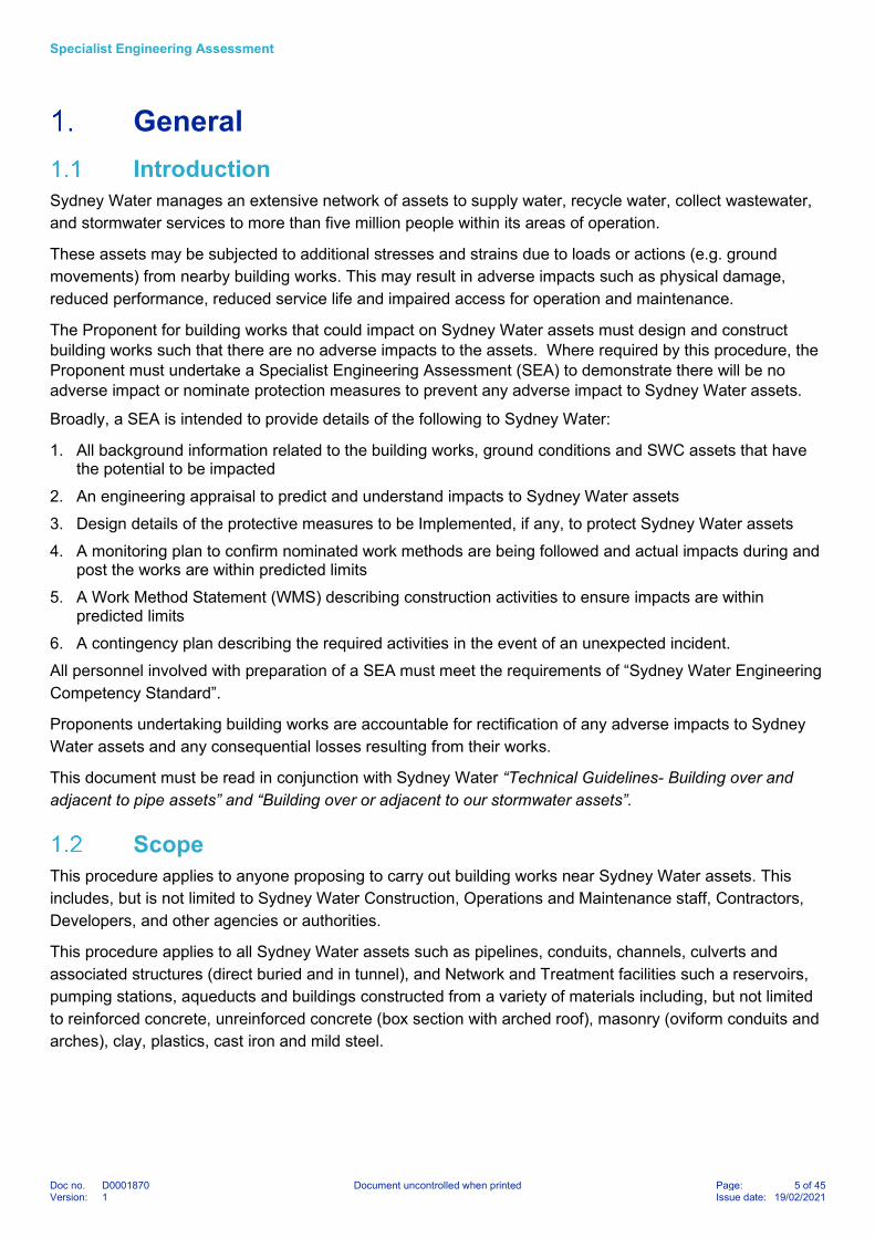
Construction joints: Unreinforced concrete linings were typically constructed in multiple pours. The quality of Construction joints will vary depending on the locations and must be included in models. In the absence of specific data on construction joints, for a typical unreinforced concrete lining, construction joints must be modelled at the base and top of the tunnel walls as shown in Figure 7: 7. Construction joints must be modelled with limited to no tensile capacity depending on location, type and methodology for the construction.
Parameters: Table 2 and Table 3 provide parameters that would be considered reasonable upper bound values in many situations for unreinforced concrete linings for non-linear analysis. The Proponent is responsible in choosing appropriate parameters relevant to the nature and condition of the structure.
Sensitivity analysis: A parametric study must be performed to understand the sensitivity of the structure to variations in load, ground conditions and liner properties. The stability of the structure is sensitive to the assumed strength of cold joints, tensile capacity and fracture energy of concrete. Hence, these parameters must be subjected to sensitivity analyses.
Collapse mechanism and deformation: When the total stress level including those from the impacts of the development exceeds 50% of the member loading capacity, the analysis must continue until the collapse of the structure by scaling up the imposed loads or displacements. The assessment results must include an appraisal of the collapse mechanism demonstrating the likely failure mechanism and a plot illustrating the evolution of deformations under the applied load.
Figure 7: Location of construction joints for a typical Sydney Water unreinforced concrete asset
Location of construction joints

Specialist Engineering Assessment
Doc no. D0001870 Document uncontrolled when printed Page: 22 of 45Version: 1 Issue date: 19/02/2021
Table 2: Suggested upper bound shear capacity and tensile capacity to be adopted for construction joints
Parameter Unit Base Construction Joint - Horizontal
Base Construction Joint - Vertical
Top Construction Joint
Soil/rock model - Mohr-Coulomb Mohr-Coulomb Mohr-Coulomb
Drainage type - Drained Drained Drained
Cohesion kPa 100 0 50
Friction angle o 34 34 34
Allowable flexural tensile Stress
kPa 500 0 250
Table 3: Suggested upper bound parameters for unreinforced concrete (not at construction joints)
Parameter Unit Monolithic Concrete
Drainage type - Non-porous
Young’s modulus of concrete kPa 24x106
Poisson’s ratio - 0.2
Allowable compressive stress
(f’c = 20 MPa)
kPa 12x103
Allowable flexural tensile stress kPa 1000
Residual tensile strength of concrete kPa 0
Tensile fracture energy of concrete kPa 0.1
Structural Appraisal of Predicted Impacts
4.5.1 Design of Adjacent Structures
In addition to appraising Sydney Water assets for the effects of the Proponents building works, the proposed
development, considering the effects resulting from minor, major, or catastrophic changes to Sydney Water
assets over the life of the assets, must also be assessed. These changes may include changed ground
water pressure due to a blocked or leaking asset, external excavation near the asset, due to another
development or maintenance work requirements.
The proponent must allow for excavation and the associated loss of supporting material around an asset
during access for maintenance and repair of the asset. An excavation and failure envelope at least 1 m
below and adjacent the asset level extending at 45 degrees to the surface must be considered.
4.5.2 Purpose of Structural Appraisal
The purpose of structural appraisal is to understand the effects of predicted impacts of Building Works on
Sydney Water assets and to assess whether they are acceptable for the strength, durability, serviceability
and maintenance of the assets.

Specialist Engineering Assessment
Doc no. D0001870 Document uncontrolled when printed Page: 23 of 45Version: 1 Issue date: 19/02/2021
The proposed building work must not increase the demand level (i.e. stress, deformation) by more than 25%
of the total asset capacity limits. The maximum utilisation factor shall be limited to 75% of the total asset
structural capacity.
Although a structural appraisal must be undertaken after geotechnical analysis of an asset, the overall
process may be iterative. Ground-structure interaction may require iterative analyse using specialist
geotechnical and structural software to calibrate the structural and ground responses.
4.5.3 General Approach for all Asset Types
All appraisals must comply with the requirements of all relevant federal and state laws and regulations in
place in New South Wales. Where an appraisal is subject to the control of statutory or regulatory authorities,
the appraisal must comply with the requirements of those authorities.
All appraisals must comply with Sydney Water standards and specifications, WSAA Codes and Sydney
Water Editions, and referenced Australian Standards and Codes. If an international or overseas standard or
code is proposed in-lieu of an Australian Standard, a detailed assessment showing the proposed standard
or code is equivalent or superior to the Australian Standard must be submitted to Sydney Water for
acceptance. If there is no Australian Standard of code covering the subject, then an international or
overseas standard or code may be used, subject to acceptance by Sydney Water.
Regardless of the type of asset, its location, size, or material, the general appraisal approach must remain
the same. The approach must be to use accepted engineering principles, rational analysis, codes and
standards, published literature, and risk management to assess the effect of adjacent development on the
asset.
The appraisal must determine whether the asset will during its life:
Perform adequately under all reasonably expected design actions
Sustain local damage without compromising its operability or impacting the environment
Not compromise the health and safety of those who work on or use the asset
Require higher level of maintenance or more frequent condition assessment
For new assets that have a known form, the appraisal may comply with the requirements of the “Sydney
Water Technical Specification – Civil” and referenced standards including AS 3600, AS 3735, and AS
2566.1.
However, contemporary design criteria for new structures may not be entirely applicable to the structural
appraisal of existing old assets.
Existing assets have less certain properties, may contain defects, and are often outside the scope of
published standards. The proponent must recognise the limitations in applying contemporary standards and
codes to existing structures. It is necessary to apply a full range of engineering principles to assess an
asset.
The structural appraisal must include an appraisal of the whole asset including associated structures such
as thrust and anchor blocks.

Specialist Engineering Assessment
Doc no. D0001870 Document uncontrolled when printed Page: 24 of 45Version: 1 Issue date: 19/02/2021
4.5.4 Structural Criteria
Broadly, the structural appraisal criteria are defined as limit states beyond which the structure no longer achieves it required performance. The limit states are:
Ultimate limit states (states associated with collapse or other similar forms of structural failure), including:
– Stability-, buckling, sliding, and overturning
– Strength.
Serviceability limit states (states that correspond to conditions beyond which specified service criteria for the structure or structural element are no longer met), including:
– Deflection or rotation
– Deformation
– Cracking
– Vibration
– Durability.
Any other limit state that may reduce the reliability and robustness of the asset must be considered.
The limit states must be assessed for design actions including:
Permanent actions
Imposed actions
Earthquake actions corresponding to Importance Level of 3 for sewer & stormwater assets and 4 for water distribution assets
Liquid pressure actions
Ground water actions corresponding to 1 in 100-year return period
Earth pressure
Ground movement
Thermal effects
Time effects.
Static and dynamic loading must be considered. Cyclic loading causing fatigue must be considered.
An important serviceability requirement is the need to maintain the liquid retention function of assets that convey water, wastewater, or stormwater.
Cracks exceeding 0.2 mm in width of an asset may cause exfiltration of water from the asset, or infiltration of other substances (soil, groundwater, or organic matter) into the asset. The effects of exfiltration and infiltration include:
Reduced performance
Induced corrosion
Loss of efficiency
Environmental consequences
Erosion of supporting ground causing uneven loading or deformation of the asset and subsequent exceedance of ultimate or serviceability limit states.
The appraisal must make allowance for past and future effects. Past deformation and loading of an asset must be included in the assessment. Assets must have reserve capacity and robustness to withstand future impacts with appropriate levels of reliability.

Specialist Engineering Assessment
Doc no. D0001870 Document uncontrolled when printed Page: 25 of 45Version: 1 Issue date: 19/02/2021
4.5.5 Appraisal of Buried Pipes
Appraisal of buried pipes must consider:
Transverse effects
– Flexible pipes – to Sydney Water Technical Specification – Civil and AS 2566.1. The maximum deflection of existing SCL pipes with external gunite coating must be limited to 2%.
– Rigid pipes – to Sydney Water Technical Specification – Civil and AS/NZS 3725, AS 4060, or BS EN 1295-1 National Annex A as appropriate.
Longitudinal effects – including tensile/ compressive strains, joint rotation, joint pull-out, joint compression, curvature, and tilt.
Combined Transverse and longitudinal effects
4.5.6 Appraisal of Masonry Conduits
Appraisal of buried masonry conduits such as brick oviform structures and arched roof conduits must consider:
Transverse effects – cracking, loss of strength, and instability due to cross sectional distortion and transverse stresses and strains caused by imposed deformation or load.
Longitudinal effects – cracking, tilt, instability due to deformation and longitudinal stresses and strains due to deformation in the vertical and horizontal planes.
Application of AS 3700 for strength and serviceability, where appropriate.
Application of analysis methods and parameters in Section 4.4
Reduced material properties and capacity reduction factors reflecting the age of construction must be considered.
Figure 8: Example of a longitudinal crack in a brick oviform conduit
Specialist Engineering Assessment
Doc no. D0001870 Document uncontrolled when printed Page: 26 of 45Version: 1 Issue date: 19/02/2021
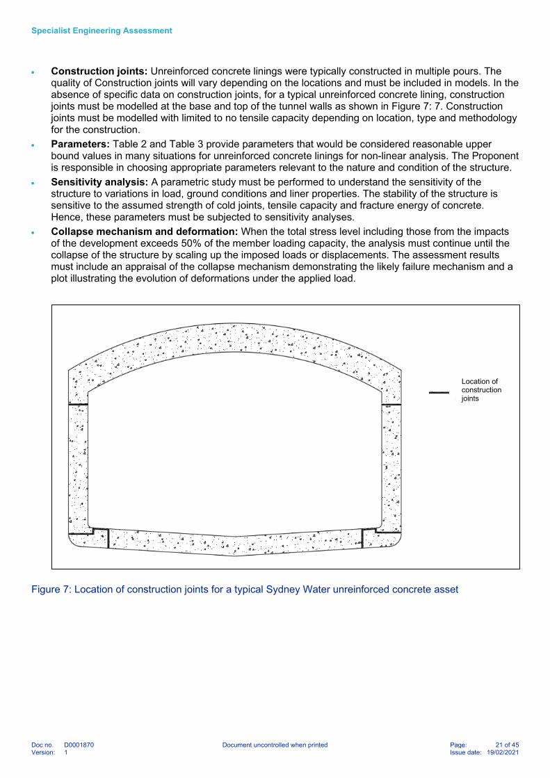
4.5.7 Appraisal of Buried Unreinforced Concrete Lined Assets
Appraisal of buried unreinforced concrete conduits must include:
Transverse effects
Longitudinal effects
Application of the principles of AS 3600 and AS 3735 for strength and serviceability, where appropriate.
Application of analysis methods and parameters in Section 4.4
Stresses due to restraint from creep, shrinkage, and temperature effects.
Reduced material properties and capacity reduction factors reflecting the age of construction.
Torsion and twisting effects
Figure 9: Typical unreinforced concrete lined tunnel showing reduced section
4.5.8 Appraisal of Buried and Above Ground Reinforced Concrete Assets
Appraisal of buried and above ground reinforced concrete conduits must include:
Application of AS 3600 and AS 3735 for strength and serviceability, where appropriate
Reduced material properties and capacity reduction factors reflecting the age of construction.

Specialist Engineering Assessment
Doc no. D0001870 Document uncontrolled when printed Page: 27 of 45Version: 1 Issue date: 19/02/2021
Threshold Impact Criteria Threshold Impact values may be one of the following:
Predicted value in analysis models
Nominated values in standards, codes of practice or statutory requirements
Judicious values based on experience.
The threshold impact values in Tables 4 & 5 are suggested to facilitate preparation of the SEA to
demonstrate that the risks to Sydney Water assets are acceptable. They are for guidance only and
represent levels where the risk of damage is considered low. They are not safe or allowable values. Sydney
Water does not guarantee that even lower values will not result in damage. It is the Proponent and their
consultant’s responsibility to select appropriate impact criteria for the specific site
Engineers must exercise discretion when dealing with complex cases, sensitive and critical assets, and
assets known to be in poor condition and vulnerable to damage. These threshold values may not be
adequate when the failure mode is brittle, and failures are sudden and without warning. More stringent
values may be warranted, or multi-tiered values may need to be set.
The Proponent must note they are accountable for rectification of any damage to Sydney Water assets,
including any consequential damage.
The criteria in Table 4 apply to longitudinal impacts on Sydney Water pipe assets due to ground movements
caused by building works, where there are no transverse impacts (e.g. cross-sectional distortion). In the event
when there is a transverse impact, the combination effects need to be fully analysed and assessed.
Table 4: Threshold Impact Criteria for longitudinal impacts for lower risk pipe assets up to DN600
Pipe material Maximum increase in joint pull out (mm)
Maximum increase in joint rotation
(degrees)
Maximum increase in pipe strain - tensile
(micro-strain/µ )
Maximum increase in pipe strain -compressive
(micro-strain/µ )
Cast Iron Cement Lined (CI or CICL)
5 0.1 80 350
Vitrified Clay (VC)
Earthenware (EW)
Salt Glazed Ware (SGW)
5 0.1 80 150
Polyvinylchloride (PVC) 10 0.3 1,000 1,000
Glass Reinforced Plastics (GRP)
10 0.1 200 200
Ductile Iron Cement Mortar Lined (DICL)
10 0.3 200 200
Reinforced Concrete (RC) 5 0.1 20 100
Steel cement Lined Rubber Ring Joint (SCL RRJ)
10 0.3 150 150
Steel cement Lined Welded Joint (SCL WJ)
N/A N/A 150 150
Polyethylene (PE) N/A N/A 2,500 2,500

Specialist Engineering Assessment
Doc no. D0001870 Document uncontrolled when printed Page: 28 of 45Version: 1 Issue date: 19/02/2021
Note: Table 4 is applicable for buried pipe assets, in sound condition, and laid in a typical soil trench in stable ground. Alternative criteria shall be developed for other pipe types and sizes, pipes/conduits of unreinforced concrete or brick construction, concrete encased pipes, pipes on piled/special supports and pipes in tunnels or of other unusual construction or ground conditions. The criteria apply to longitudinal impacts on Sydney Water pipe assets due to ground movements caused by nearby excavation and/or tunnelling where there are no transverse impacts (e.g. cross-sectional distortion).
The susceptibility of Sydney Water assets to crack damage depends on several factors including but not
limited to type the assets, environmental consideration and condition of the structure.
The criteria in Table 5 applies to longitudinal and transverse impacts on higher risk Sydney Water assets
due to ground movements caused by building works.
This includes the maximum crack size for various assets from structural aspects only. More strict
requirements might apply due to other performance or serviceability requirements.
Table 5: Threshold impact criteria for higher risk assets
Parameter Brick Oviform Unreinforced concrete tunnel lining (design wall thickness in the order of 250 mm***)
Maximum increase in tensile strain due to longitudinal and transverse effects (micro-strain/µ)
250 20
Maximum drift* due to transverse effects
H/1500 H/750
Minimum incremental radius of curvature (km)
60 60
Minimum safety margin to collapse 3 3
Maximum crack width (mm) 0.2 0.2
Maximum depth of crack One fifth of section thickness One fifth of section thickness
Notes: * Drift is the differential horizontal displacement between the top and bottom of the tunnel ** H = Total tunnel height *** For other wall thickness, alternative impact criteria must be developed The radius of curvature is calculated from the longitudinal deformed shape induced on the asset by the building works Each criterion in Table 5 must be satisfied
Gravity sewers and stormwater assets must also be assessed for impacts due to tilt, that is, change in pipe slope due to ground movements. It must be demonstrated that residual pipe slope will not be less than the absolute minimum grades nominated in Table 4.6 of the Sewerage Code - Sydney Water Edition (Ref 2).
Vibration Limits The susceptibility of Sydney Water assets to vibration damage depends on a range of factors including the
nature of the ground, the geometry, materials and condition of the structure, the nature of the vibrations and
their proximity to the structure and whether they are long acting or intermittent.

Specialist Engineering Assessment
Doc no. D0001870 Document uncontrolled when printed Page: 29 of 45Version: 1 Issue date: 19/02/2021
Table 6: Threshold Vibration Limits
Asset type Threshold values for velocity (PPV) measured on the asset in mm/s
Brittle Pipe assets –
RC, VC/ EW, CICL
Maximum PPV for intermittent vibrations 10mm/s
Maximum PPV for continuous vibrations 5mm/s
Ductile Pipe assets –
SCL, DI, PVC, PE, PP, GRP
Maximum PPV for intermittent vibrations 20mm/s
Maximum PPV for continuous vibrations 10mm/s
Masonry 3 mm/s
Unreinforced concrete 3 mm/s
Note: Table 6 is applicable for buried assets, in sound condition, and laid in a typical soil trench in stable ground. Alternative criteria shall be developed for other asset types, above ground assets, concrete encased pipes, pipes on piled/ special supports and pipes in tunnels or of other unusual construction or ground conditions.
Asset protection measures Where predicted impacts are assessed that it may adversely impact the structural integrity of the asset,
protection measures must be employed. Various protection measures are available depending on the assets
and exposed risk level. The spatial extent and level of protection must be determined based on the
outcomes of the geotechnical and structural appraisal, and operation and maintenance considerations. No
building works are permitted in easements, over pressure pipelines, or over gravity sewers greater than or
equal DN750.
Commonly adopted protection measures include:
Exclusion/clearance zones: A barricaded exclusion zone to reduce/eliminate impacts from external activities. Barricade tape is not considered as an acceptable form of marking no entry zones.
Protection slabs or temporary steel plates can be used to prevent impact due to loading subject to site specific condition and assessment. If slabs are used as permanent installations, the size, weight and lifting anchors of the slabs must be defined to allow easy access for future maintenance/repair.
Strengthening: Reinforced concrete encasement could be considered if it will not impact accessibility and future maintenance (e.g. for rubber ring jointed pressure pipes).
Asset rehabilitation: Several trenchless rehabilitation methods are available to repair existing pipelines such as Cured-in-place pipe (CIPP), spiral wound in place Liner, slip lining, joint sealing repairs.
Asset renewal: Permanently re-lay the asset at the current location with materials that can tolerate higher impacts
Asset adjustment: Realigning the asset to avoid the influence zone.
Other mitigation measures can be adopted in consultation with Sydney Water to reduce consequence of failures. These could include temporary shutdown of pressure mains, or bypass arrangements of gravity mains if permissible, such as bypass pumping from an upstream to downstream maintenance hole.

Specialist Engineering Assessment
Doc no. D0001870 Document uncontrolled when printed Page: 30 of 45Version: 1 Issue date: 19/02/2021
In lieu of reinforced concrete encasement to make pipes ‘maintenance free’, internal lining may be
considered for existing pipes less than or equal to DN600 in size to increase robustness. Maintenance free
installations are required when structures are built over SW pipe assets that restricts future external access
for maintenance/ repair). Lining may only be considered for gravity pipes in good condition embedded in
favourable ground conditions. A liner installed inside an existing pipe in poor condition, or embedded in poor
ground conditions (e.g. soft or weak/ compressible soils), is not sufficiently robust for cases where future
external access for maintenance/ repair is restricted.
Prior to lining, an internal inspection of the pipe must be undertaken to allow evaluation of the current
condition by a competent engineer. Where adopted, lining must comply with requirements of Sydney Water
Specification SS 201, and only approved rehabilitation products are permitted (refer to List of Deemed to
Comply Products for Pipeline Rehabilitation). The host pipe must be considered as fully deteriorated for
calculation of liner thickness to provide adequate robustness.
These are minimum requirements for liners only. Additional requirements may be required depending on
outcomes of SEA. The feasibility of lining systems must be confirmed based on site-specific assessment.
The basis and liner design must be provided with the SEA submission.
Instrumentation and Monitoring plan An Instrumentation and Monitoring Plan is required where Sydney Water assets may be affected by the
external activity. The purpose of monitoring is to understand the behaviour of the asset during and after the
works and to validate the predicted modelling results and confirm impacts are within predicted limits
Depending on the nature and importance of the asset the following (but not limited to) instruments may be
used for monitoring:
Inclinometers for lateral ground movement, located near the asset at locations where maximum ground movements are expected.
Extensometers and strain gauges for stresses and strains inside the asset
Piezometers for groundwater
General site surveillance to check for leakages or odours and confirm work methods in accordance with WMS
Monitors to assess the impact of works on existing cracks and joints, and visual inspections for development of new cracks
Conventional survey methods to measure ground surface and excavation face and retaining wall movements.
Vibration monitors to assess vibrations at Sydney Water assets due to construction activities
Vibration monitoring is required if vibration inducing activities such as: blasting, demolition, excavation piling
or drilling works are conducted adjacent to Sydney Water assets. Monitored peak particle velocities must be
compared against the site-specific impact criteria.
If agreed with Sydney Water, where the risks to Sydney Water assets are demonstrated as low, a general
site surveillance along with pre-construction and post-construction inspections of the asset may satisfy the
requirements. However, if the potential for risk is to be higher or the Sydney Water asset is considered
critical; a key plan describing the monitoring instruments and locations must be provided along with the
frequency of measurements.

Specialist Engineering Assessment
Doc no. D0001870 Document uncontrolled when printed Page: 31 of 45Version: 1 Issue date: 19/02/2021
Monitoring frequency may vary according to construction stages. Pre-construction monitoring is required to
establish baseline readings and understand background noise. Daily monitoring may be required during
construction and could then be reduced to a weekly or monthly basis until there is no significant change in
movements for a number of consecutive monitoring rounds. Additional, CCTV or visual internal inspections
of Sydney Water assets may also be required at critical stages of the project for structural appraisal.
Weekly or daily monitoring reports must be provided to Sydney Water for review. Reports provided to
Sydney Water must be interpreted reports, clearly indicating the general trends in movements. However,
raw readings must also be submitted to Sydney Water at a frequency agreed with Sydney Water.
Monitoring trigger values must be adopted based on results of engineering assessment. Recommended
trigger levels must include Alert, Action and Alarm levels. The trigger values should typically be as follows:
Alert: If displacement is less than 70% of agreed value. Works may continue.
Action: If displacements are greater than 70% but less than 100% of the agreed value, Sydney Water must be notified, and monitoring data must be reviewed. The frequency of the monitoring must be increased. Works may continue.
Alarm: If the displacements are greater than the agreed value, the works must be stopped, and Sydney Water must be informed immediately. Measures must be taken according to the contingency action plan to safeguard Sydney Water assets. Numerical models must be recalibrated using the monitoring results. Resumption of the works will be subject to Sydney Water approval.
A site-specific plan to monitor the impact of works outlining monitoring parameters, trigger levels, actions
when trigger levels are exceeded and nominate a responsible person for each task. Trigger levels to be
implemented must be provided as in Table 7.
The monitoring plan must outline the following:
Key plan of location, method and form of measurement,
Frequency and accuracy required
Measuring equipment
Measuring technique
Submission of records to Sydney Water representative
Roles and responsibilities
Table 7: Example of contents in instrumentation monitoring points & limits
Location ID Elevation Alert (units)
Action (units)
Alarm (units) Remarks
Location of monitoring point (key plan to be provided)
Depth of the monitoring (where applicable. e.g.: Extenso meter)
70% of maximum predicted
<100% of maximum predicted
>=100% of maximum predicted (but not greater than asset capacity)
(As appropriate)

Specialist Engineering Assessment
Doc no. D0001870 Document uncontrolled when printed Page: 32 of 45Version: 1 Issue date: 19/02/2021
Work Method Statement Based on outcomes of the SEA, a Work Method Statement (WMS) specifically for the purpose of asset
protection must be prepared. The WMS must be concise and focus on describing the hazards and risks to
Sydney Water assets on the construction site and the control measures to be put in place. The WMS must
contain the following:
Scope of work
Plant, materials, and equipment to be used
Sequence of work
Inspection and testing requirements
Identification the risks/ hazards to SW assets
Specification of the control measures to be implemented
Implementation of monitoring and contingency plans
Responsibilities for each task
Contingency plan Where identified by risk assessment, or as directed by Sydney Water, the Proponent must submit a
Contingency Plan to manage the consequences and mitigate damage to Sydney Water assets as a result of
the building works. The Contingency Plan must be based on a risk assessment to identify potential site-
specific risks in consultation with Sydney Water stakeholders. The plan must highlight site specific issues,
potential risks and detail the measures undertaken to limit the impact of an unexpected incident and
demonstrate due diligence against potential regulatory action by the NSW Environmental Protection Agency.
The Contingency Plan must also include the reporting procedure, contact details of all relevant parties, roles
and responsibilities of different parties, emergency repairs, equipment and material availability for repairs in
case of an incident. The plan may need to be trialled on site in high risk situations to confirm the practicality
and suitability in consultation with Sydney Water. When working in and around Sydney Water hydraulic
assets, Health and Safety Procedure HSP0070 must be followed.
The Contingency Plan must detail emergency response measures in the event of a failure and disruption of
service, including:
provision of resources to respond to an emergency event
temporary flow bypass arrangements to minimise service disruption and allow repairs
availability of repair or renewal materials such as pipes, special pipe couplings or clamps
management of site access and traffic control.
Table 8: Contingency plan
Risks Mitigation measures adopted in design phase
Contingency plan Responsible person
List of perceived risks Action to mitigate risk before it happens
Action to deal with risk after it happens
Add person in charge for implementation of contingency plan including contact details

Specialist Engineering Assessment
Doc no. D0001870 Document uncontrolled when printed Page: 33 of 45Version: 1 Issue date: 19/02/2021
Specialist Engineering Assessment Report Contents The SEA report must have the following components
Executive Summary
References: A list of all references and drawings referred to in the assessment.
Description of the works and external activities in the vicinity of the asset: This must include the worst
case temporary and long-term loads and actions likely to be acting on the asset. A key plan and critical
section(s) adopted for the impact assessment must be provided. Clearances from the external activities to
Sydney Assets must be clearly shown.
Site location: A key location map showing the assets under consideration with respect to the development.
Subsurface conditions: Subsurface conditions considered for the analysis, based on a geotechnical
interpretative report. The relevant factual geotechnical information, such as borehole logs and laboratory
test results must be provided as well as interpreted models.
Groundwater conditions: The groundwater conditions in and around the site as well as the influence of
building works on the ground water regime must be described.
Description of the asset: A general description about the assets based on HYDRA information, WAC
drawings, survey information and condition assessment reports. This must include the dimensions of the
asset, loads acting on the asset and, structural properties. It must also describe the present condition of the
material and the asset, not just the as-built details.
Construction equipment and vibrations: A description of the construction equipment and the maximum
vibration estimated must be provided.
Construction sequence: The construction sequence to be adopted at site must be included.
Ground-structure interaction analysis: A ground structure interaction analysis must be undertaken by
adopting the actual loading and unloading sequences. Present stress conditions acting around the asset
must be replicated based on the available information. For critical assets, this must include the construction
methodology adopted and stresses profile generated.
The analyses must quantify impacts such as additional load, ground movements and resulting additional
stress and curvature in line with requirements of section 4.4.1.
Key assumptions and sensitivity analyses: Report the key assumptions and uncertainties that may
impact the outcomes. Sensitivity analyses must be conducted for the geotechnical and structural material
parameters adopted from the geotechnical interpretive report. Strength as well as stiffness parameters must
form the part of sensitivity analysis.
Structural appraisal: Describe the response of the asset to impacts and compare with Ultimate (ULS) and
Serviceability (SLS) Limits.
Results: The analyses must include the longitudinal and transverse impacts on the asset. Both longitudinal
and transverse profiles must be provided with radius of curvature and tensile strains generated along the
profile. The longitudinal profile must clearly indicate the locations where strains exceed the site-specific
impact criteria. The results of the maximum joint rotation as well as the maximum pull-out must also be
assessed and compared with the site-specific impact criteria.

Specialist Engineering Assessment
Doc no. D0001870 Document uncontrolled when printed Page: 34 of 45Version: 1 Issue date: 19/02/2021
Risk Assessment: Identify and analyse potential issues that may adversely affect Sydney Water assets.
The report must detail the severity of the risk, control measures and effectiveness of those measures. For
high risk or critical assets, Sydney Water may require formal Risk Assessment to be undertaken.
Contingency Plan: A plan to manage the consequences and mitigate damage in the event of an incident as
a result of the building works as required by risk assessment or specified by Sydney Water.
Protection works for the asset: Sydney Water assets may require strengthening, renewal or relocation
due to proposed construction activity. Detail of the design of any protection works to be undertaken for the
asset must be included in the SEA. The protection works must describe any restrictions in loadings around
the asset and construction methodology. This must also include restrictions imposed on the limits of
concrete strength achievement before excavation, allowable variation of geotechnical strata based on the
design, quality control measures or any other points which might adversely impact the asset.
Instrumentation and Monitoring plan: Details of instrumentation and monitoring required must be
presented in the SEA and referenced to a more detailed Monitoring Plan, if required.
Engineering Competency Records: Detail the competency of all personnel engaged to prepare and verify the SEA in accordance with the Engineering Competency Standard.
Independent Verification Records: Records of independent verification including the independent verification certificate; when necessary, as stipulated in the Sydney Water Engineering Competency Standard. A comment register with all comments and responses by independent verifier also must be submitted to Sydney Water.
Appendix C contains the summary of table of content discussed above and is required to be included as part
of each SEA submission.

Specialist Engineering Assessment
Doc no. D0001870 Document uncontrolled when printed Page: 35 of 45Version: 1 Issue date: 19/02/2021
References
Document type Title Document Reference
Policies, Standards and specifications
Sydney Water Technical Specification - Civil CPDMS0023
Policy - Building over or adjacent to Sydney Water assets
D0001720
Technical Guidelines – Building over and adjacent to pipe assets
ACDP0254
Policy – Building over or adjacent to our stormwater assets
1260449 | SW119 11/20
Guide – Building over or adjacent to our stormwater assets
SW69 09/20
Lining for Circular Non-Man Entry Pipes SS 201
List of Deemed to Comply Products for Pipeline Rehabilitation
ACP0003
Sydney Water Engineering Competency Standard
D0000833
Technical Standard – Avoid Fails Sewer Level 2 Condition Assessment
WWAS0038
Geotechnical site investigations AS 1726: 2017
Structural vibration Part 3: Effects of vibration on structures
DIN 4150-3
Code of practice for noise and vibration control on construction and open sites – Part 2: Vibration
BS 5228-2:2009
Evaluation and measurement for vibration in buildings
BS 7385-2:1993
Explosives-Storage and use Part 2: Use of explosives
AS 2187.2-2006
Development Near Rail Tunnels, version 1.0 TfNSW (T HR CI 12051 ST)
Health and Safety Procedure - Flow Isolation and / or Flow Management (FIFM)
HSP0070
Buried flexible pipelines – Part 1: Structural design
AS/NZS 2566.1:1998
Masonry Structures AS 3700:2018
Sewerage Code of Australia – Sydney Water Edition Version 4
WSA 02-2002
Concrete structures AS 3600:2018
Design for installation of buried concrete pipes
AS/NZS 3725:2007
Concrete structures for retaining liquids AS 3735:2001
Loads on buried vitrified clay pipes AS 4060:1992

Specialist Engineering Assessment
Doc no. D0001870 Document uncontrolled when printed Page: 36 of 45Version: 1 Issue date: 19/02/2021
Structural design of buried pipelines under various conditions of loading – Part 1: General requirements
BS EN 1295-1:2019
Guidance on piling, heavy loads, excavations, tunnelling and dewatering
Thames Water
Other documents Settlement of buildings and associated damage
Burland et al. (1978)
Behaviour of foundations and structures Burland et al. (1978)
A methodology for evaluating potential damage to cast iron pipes induced by tunnelling
Bracegirdle et al. (1996)
Prediction of ground movements and assessment of risk of building damage
due to bored tunnelling
Mair.R.J et al. (1996)
Tunnel construction impact on utility pipelines New B (2017)
Sydney Sandstone and Shale Parameters for Tunnel Design
Bertuzzi.R (2014)
An Alternative Approach for Assessing In-Situ Stresses in Sydney
Oliveira and Parker (2014)
Prediction and effects of ground movements caused by tunnelling in soft ground beneath urban areas
CIRIA SP 30
Utility Protection While Tunnelling in an Urban Environment for the DC Clean Rivers Project
Kottke P. et al. (2014)

Specialist Engineering Assessment
Doc no. D0001870 Document uncontrolled when printed Page: 37 of 45Version: 1 Issue date: 19/02/2021
Ownership
Ownership
Role Title
Group Asset Lifecycle
Owner Manager, Engineering
Author Robert Loncar, Lead Civil Engineer, Specialist Engineering
Change history
Version No. Prepared by Date Approved by Issue date
1 Robert Loncar, Dinesh Dineshharan, Christie Sebaratnam, Paymon Aria, Nick Moses
19/02/2021 Norbert Schaeper 19/02/2021
Appendices Appendix Title
A SEA Process Flowchart
B SEA Submission Checklist
C Table of Contents Required in the SEA Report

Specialist Engineering Assessment
Doc no. D0001870 Document uncontrolled when printed Page: 38 of 45Version: 1 Issue date: 19/02/2021
Appendix A: SEA Process flowchart

Specialist Engineering Assessment
Doc no. D0001870 Document uncontrolled when printed Page: 39 of 45Version: 1 Issue date: 19/02/2021
Start
Identify influence zone(eg.: ground movement zone)
Define Building Works and External Activities
Identify All Sydney Water assets in the influence zone
Understand Condition of SW Assets (eg.: Condition assessment, visual
inspection, CCTV)
Gather and review all relevant existing data
Understand engineering properties of SW AssetsCarry out additional investigations
(e.g.: Geotechnical site investigations.) As required
Personnel Competency Compliant to SWC Engineering Competency Standard?
Yes
Appoint Engineering Personnel
No
Understand Potential Risks to SWC Assets
Understand Risks to SWC Operational and Maintenance
RequirementsUnderstand risks to Public health,
Environment, Community, Safety and others
Potential Risk to SWC warrants detailed analyses?
Consult Sydney Water, if required for high risk or critical assets
Carry out detailed numerical ground- structure interaction
analyses
Carry out simplified empirical checks and/or apply protection methods
Yes
No
Obtain Independent Verification & update
SEA Report
Yes
Personnel Competency Compliant to SWC Engineering Competency Standard?
No
No objection notice issued by SWC
No
End
Implement Work Methods and Instrumentation & Monitoring Plan
in SEA
Yes
Complete monitoring activities and carry out post construction condition
assessment
SWC issue no further commentsFurther Actions to be discussed with SWC
NoYes
Prepare SEA Report
Independent Verification Required?
Yes
Submit to Sydney Water Review
Updated Risk profile is accepted and no objection notice issued by SWC
Prepare SEA Report
Submit to Sydney Water Review
Yes
NoNo
Process
Decision
Reference to Checklist
PROCESS FOR SPECIALIST ENGINEERING ASSESSMENT ON SYDNEY WATER ASSETS
Sydney Water Consultation
Appoint Competent Engineering Personnel
3
2
1.2
4.1
4.2
4.1
4.4
4.3 & 4.4
4.3 & 4.4
5-9
5-9
5-9
5-9
5-9
10
5-9
1.1
10
10
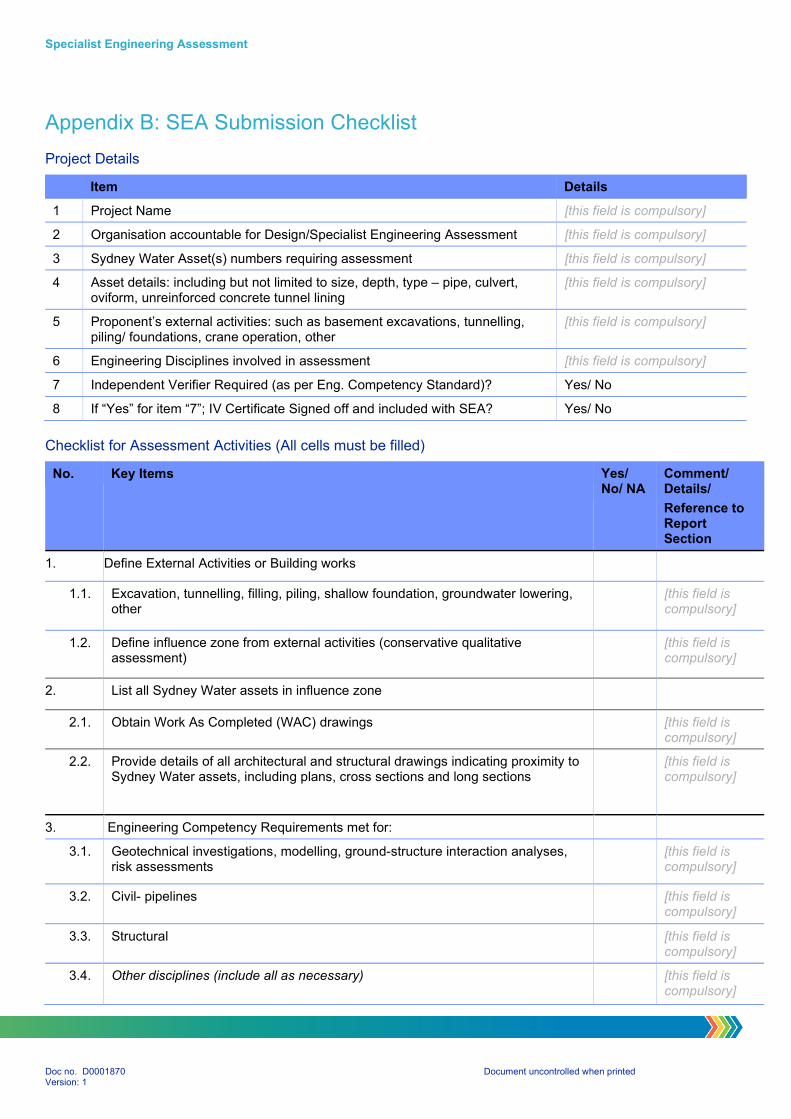
Specialist Engineering Assessment
Doc no. D0001870 Document uncontrolled when printed Version: 1
Appendix B: SEA Submission Checklist
Project Details
Item Details
1 Project Name [this field is compulsory]
2 Organisation accountable for Design/Specialist Engineering Assessment [this field is compulsory]
3 Sydney Water Asset(s) numbers requiring assessment [this field is compulsory]
4 Asset details: including but not limited to size, depth, type – pipe, culvert, oviform, unreinforced concrete tunnel lining
[this field is compulsory]
5 Proponent’s external activities: such as basement excavations, tunnelling, piling/ foundations, crane operation, other
[this field is compulsory]
6 Engineering Disciplines involved in assessment [this field is compulsory]
7 Independent Verifier Required (as per Eng. Competency Standard)? Yes/ No
8 If “Yes” for item “7”; IV Certificate Signed off and included with SEA? Yes/ No
Checklist for Assessment Activities (All cells must be filled)
No. Key Items Yes/ No/ NA
Comment/ Details/
Reference to Report Section
1. Define External Activities or Building works
1.1. Excavation, tunnelling, filling, piling, shallow foundation, groundwater lowering, other
[this field is compulsory]
1.2. Define influence zone from external activities (conservative qualitative assessment)
[this field is compulsory]
2. List all Sydney Water assets in influence zone
2.1. Obtain Work As Completed (WAC) drawings [this field is compulsory]
2.2. Provide details of all architectural and structural drawings indicating proximity to Sydney Water assets, including plans, cross sections and long sections
[this field is compulsory]
3. Engineering Competency Requirements met for:
3.1. Geotechnical investigations, modelling, ground-structure interaction analyses, risk assessments
[this field is compulsory]
3.2. Civil- pipelines [this field is compulsory]
3.3. Structural [this field is compulsory]
3.4. Other disciplines (include all as necessary) [this field is compulsory]
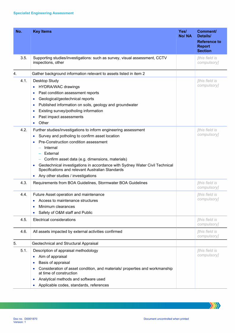
Specialist Engineering Assessment
Doc no. D0001870 Document uncontrolled when printed Version: 1
No. Key Items Yes/ No/ NA
Comment/ Details/
Reference to Report Section
3.5. Supporting studies/investigations: such as survey, visual assessment, CCTV inspections, other
[this field is compulsory]
4. Gather background information relevant to assets listed in item 2
4.1. Desktop Study
HYDRA/WAC drawings
Past condition assessment reports
Geological/geotechnical reports
Published information on soils, geology and groundwater
Existing survey/potholing information
Past impact assessments
Other
[this field is compulsory]
4.2. Further studies/investigations to inform engineering assessment
Survey and potholing to confirm asset location
Pre-Construction condition assessment
– Internal
– External
– Confirm asset data (e.g. dimensions, materials)
Geotechnical investigations in accordance with Sydney Water Civil Technical Specifications and relevant Australian Standards
Any other studies / investigations
[this field is compulsory]
4.3. Requirements from BOA Guidelines, Stormwater BOA Guidelines [this field is compulsory]
4.4. Future Asset operation and maintenance
Access to maintenance structures
Minimum clearances
Safety of O&M staff and Public
[this field is compulsory]
4.5. Electrical considerations [this field is compulsory]
4.6. All assets impacted by external activities confirmed [this field is compulsory]
5. Geotechnical and Structural Appraisal
5.1. Description of appraisal methodology
Aim of appraisal
Basis of appraisal
Consideration of asset condition, and materials/ properties and workmanship at time of construction
Analytical methods and software used
Applicable codes, standards, references
[this field is compulsory]
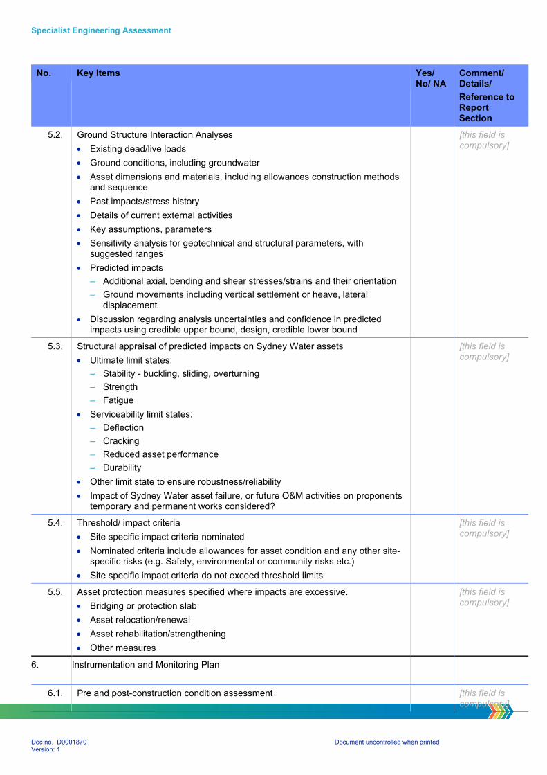
Specialist Engineering Assessment
Doc no. D0001870 Document uncontrolled when printed Version: 1
No. Key Items Yes/ No/ NA
Comment/ Details/
Reference to Report Section
5.2. Ground Structure Interaction Analyses
Existing dead/live loads
Ground conditions, including groundwater
Asset dimensions and materials, including allowances construction methods and sequence
Past impacts/stress history
Details of current external activities
Key assumptions, parameters
Sensitivity analysis for geotechnical and structural parameters, with suggested ranges
Predicted impacts
– Additional axial, bending and shear stresses/strains and their orientation
– Ground movements including vertical settlement or heave, lateral displacement
Discussion regarding analysis uncertainties and confidence in predicted impacts using credible upper bound, design, credible lower bound
[this field is compulsory]
5.3. Structural appraisal of predicted impacts on Sydney Water assets
Ultimate limit states:
– Stability - buckling, sliding, overturning
– Strength
– Fatigue
Serviceability limit states:
– Deflection
– Cracking
– Reduced asset performance
– Durability
Other limit state to ensure robustness/reliability
Impact of Sydney Water asset failure, or future O&M activities on proponents temporary and permanent works considered?
[this field is compulsory]
5.4. Threshold/ impact criteria
Site specific impact criteria nominated
Nominated criteria include allowances for asset condition and any other site-specific risks (e.g. Safety, environmental or community risks etc.)
Site specific impact criteria do not exceed threshold limits
[this field is compulsory]
5.5. Asset protection measures specified where impacts are excessive.
Bridging or protection slab
Asset relocation/renewal
Asset rehabilitation/strengthening
Other measures
[this field is compulsory]
6. Instrumentation and Monitoring Plan
6.1. Pre and post-construction condition assessment [this field is compulsory]

Specialist Engineering Assessment
Doc no. D0001870 Document uncontrolled when printed Version: 1
No. Key Items Yes/ No/ NA
Comment/ Details/
Reference to Report Section
6.2. General site surveillance:
Work methods in accordance with accepted Work Method Statement
Leakage and odours or other unexpected occurrences
[this field is compulsory]
6.3. Vibration monitoring [this field is compulsory]
6.4. Conventional survey methods to monitor ground surface and excavation face movements
[this field is compulsory]
6.5. Specialist geotechnical and structural monitoring equipment, including but not limited to inclinometers, extensometers, strain gauges and piezometers
[this field is compulsory]
6.6. Monitoring locations specified [this field is compulsory]
6.7. Monitoring frequency established at key stages pre/during/post-construction [this field is compulsory]
6.8. Monitoring trigger values established based on results of engineering assessments at alert, action and alarm levels, and implementation of Contingency Plan
[this field is compulsory]
6.9. Responsibility for monitoring actions defined [this field is compulsory]
7. Work Method Statement (WMS)
7.1. WMS incorporates requirements of SEA [this field is compulsory]
7.2. Sequence of work specified [this field is compulsory]
7.3. WMS references the Monitoring Plan [this field is compulsory]
8. Contingency Plan
8.1. Provision of resources (personnel, materials, plant, repair methods) for timely response to an incident
[this field is compulsory]
8.2. Action plan with roles and responsibilities in the event of an incident [this field is compulsory]
9. Approval of any deviations from requirements nominated the SEA procedure have been approved by Sydney Water
[this field is compulsory]
10. Obtain independent Verification, as required by Sydney Water Engineering Competency Standard
[this field is compulsory]
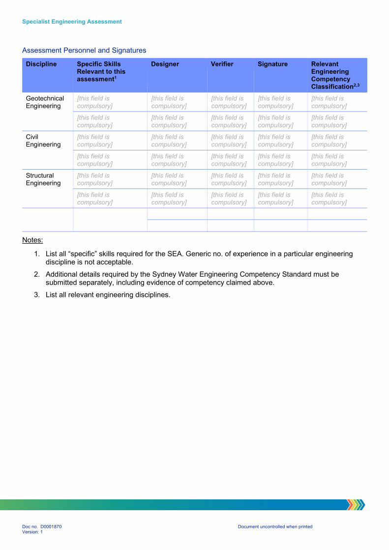
Specialist Engineering Assessment
Doc no. D0001870 Document uncontrolled when printed Version: 1
Assessment Personnel and Signatures
Discipline Specific Skills Relevant to this assessment1
Designer Verifier Signature Relevant Engineering Competency Classification2,3
Geotechnical Engineering
[this field is compulsory]
[this field is compulsory]
[this field is compulsory]
[this field is compulsory]
[this field is compulsory]
[this field is compulsory]
[this field is compulsory]
[this field is compulsory]
[this field is compulsory]
[this field is compulsory]
Civil Engineering
[this field is compulsory]
[this field is compulsory]
[this field is compulsory]
[this field is compulsory]
[this field is compulsory]
[this field is compulsory]
[this field is compulsory]
[this field is compulsory]
[this field is compulsory]
[this field is compulsory]
Structural Engineering
[this field is compulsory]
[this field is compulsory]
[this field is compulsory]
[this field is compulsory]
[this field is compulsory]
[this field is compulsory]
[this field is compulsory]
[this field is compulsory]
[this field is compulsory]
[this field is compulsory]
Notes:
1. List all “specific” skills required for the SEA. Generic no. of experience in a particular engineering discipline is not acceptable.
2. Additional details required by the Sydney Water Engineering Competency Standard must be submitted separately, including evidence of competency claimed above.
3. List all relevant engineering disciplines.
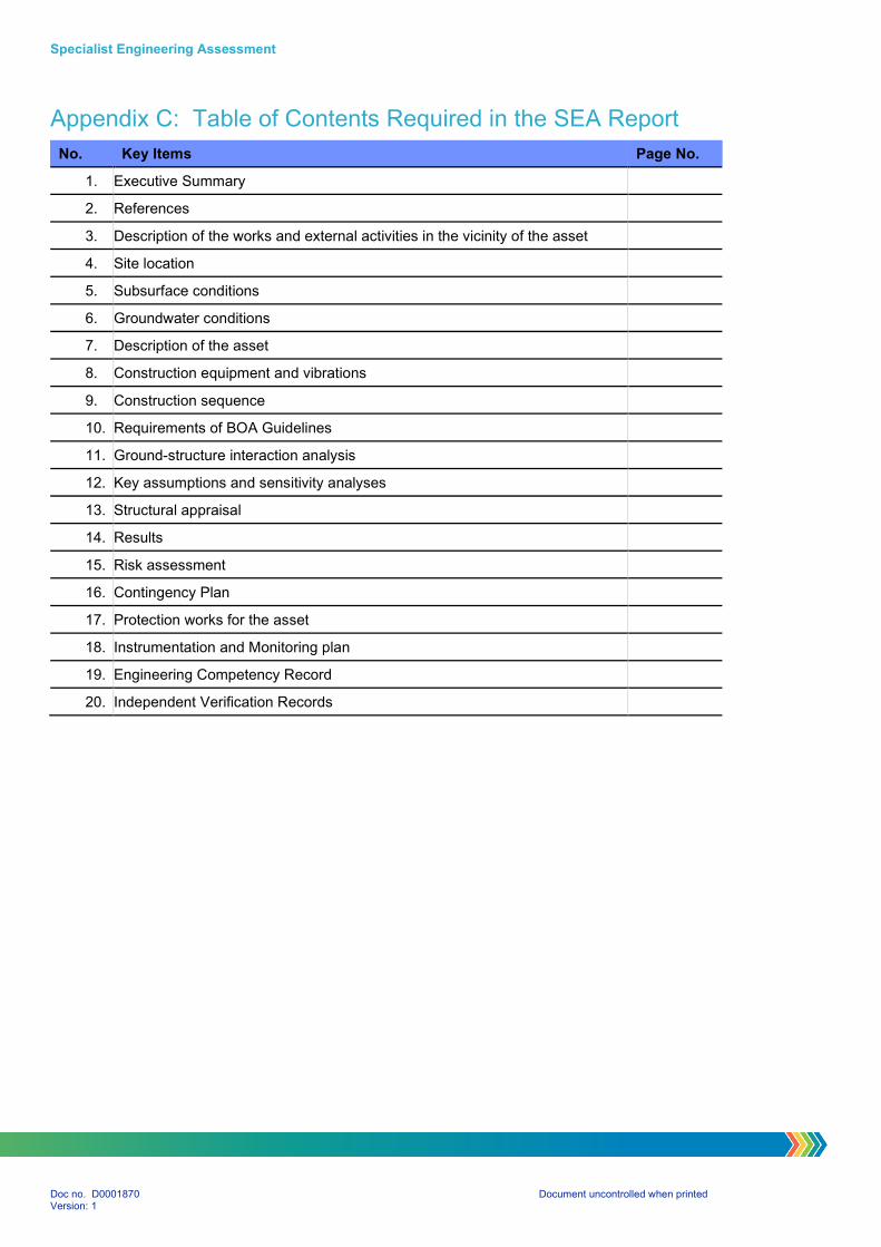
Specialist Engineering Assessment
Doc no. D0001870 Document uncontrolled when printed Version: 1
Appendix C: Table of Contents Required in the SEA Report
No. Key Items Page No.
1. Executive Summary
2. References
3. Description of the works and external activities in the vicinity of the asset
4. Site location
5. Subsurface conditions
6. Groundwater conditions
7. Description of the asset
8. Construction equipment and vibrations
9. Construction sequence
10. Requirements of BOA Guidelines
11. Ground-structure interaction analysis
12. Key assumptions and sensitivity analyses
13. Structural appraisal
14. Results
15. Risk assessment
16. Contingency Plan
17. Protection works for the asset
18. Instrumentation and Monitoring plan
19. Engineering Competency Record
20. Independent Verification Records